ageing management and re furbishment of ghana …
TRANSCRIPT

AGEING MANAGEMENT AND REFURBISHMENT OF GHANA
RESEARCH REACTOR-1(GHARR-1)
E. O. AMPONSAH-ABU, J.K GBADAGO, M.A.ADDO, R. B. M. SOGBADJI, H. C.
ODOI, K.GYAMFI, A. G. AMPONG, N. S. OPATA
National Nuclear Research Institute
Nuclear Reactors Research Centre
Ghana Atomic Energy Commission
P. O. Box LG 80
Legon – Accra
Ghana
E-mail of the corresponding author: [email protected]
ABSTRACT
The Ghana Research Reactor-1 (GHARR-1) Facility is a Miniature Neutron Source Reactor with a
rated power of 30 kW. GHARR-1 was installed and attained criticality on December 17, 1994 and
commissioned on 8th March, 1995. It has since been in operation. The routine practices and
operational procedures have been set out with clear emphasis on ageing management programme at
the facility. Some electronic components are changed regularly during maintenance sessions and
keeping to regular purification of the reactor and pool water to mitigate against corrosion. This paper
outlines the ageing management programme and mitigation practices, strategies for ageing
management; periodic safety reviews, consideration of ageing during design, design features for
components and unit replacement, top beryllium shim addition, and succession planning. Information
sharing with other operating organizations is one of the means considered by GHARR-1 to attain
excellence
1.0 INTRODUCTION
1.1 DESCRIPTION OF GHANA RESEARCH REACTOR-1 (GHARR-1)
The Ghana Research Reactor-1 (GHARR-1) is a commercial (MNSR) reactor similar to the
Canadian SLOWPOKE in design [1]. It is a 30 kW tank-in-pool reactor, producing a peak or
maximum thermal neutron flux in the core and its inner irradiation channels of 1 × 10¹² ncm-2
s-1. The reactor is designed to be compact and safe and it is used mainly for Research and
Development in reactor and nuclear engineering, neutron activation analysis, production of
short-lived radioisotopes, human resource development for Ghana’s nuclear programme and
for education and training. It is cooled by natural convection and moderated with light water.
The reactor complex contains 5 major components. These are the reactor assembly, control
console, auxiliary systems, irradiation system and the pool containing light water.
The reactor assembly consists of the reactor vessel which contains the reactor core,
beryllium (Be) reflector, small fission chambers for detecting neutron fluxes, 1 central
cadmium (Cd) control rod and its drive mechanism, and thermocouples for measuring inlet
and outlet temperatures of the coolant. The reactor vessel is a cylindrical aluminium (Al) alloy

container, 0.6 m in diameter and 5.6 m high. The container, which is built in 2 sections, is
suspended in a stainless steel-lined water pool surrounded by reinforced concrete.
The core consists of fuel elements, which form a fuel cage. The cage is inside an annular
beryllium reflector and rests on a lower beryllium reflector plate. The volume of the vessel is
1.5 m3. The fuel elements are all enriched uranium-aluminium (U-Al) alloy extrusion clad with
aluminium. They are arranged in 10 multi-concentric circle layers at a pitch distance of 10.95
mm. The element cage consists of 2 grid plates, 4 tie rods and a guide tube for the control
rod. Screws connect the 2 grid plates and 4 tie rods. The total number of lattice positions is
354 and the number of fuel elements is 344. The remaining positions are occupied with 6
dummy aluminium elements. There are 5 inner irradiation tubes installed within the beryllium
annulus. Five outer irradiation tubes are also installed outside the beryllium annulus. Figures
1 below shows the cross sectional view of the GHARR-1 core.
Figure 1 The cross sectional view of GHARR-1 core
The reflector of the MNSR reactor is made of metallic beryllium. It plays a role of reflecting
and moderating the neutrons leaked out from the reactor, hence maintaining peak thermal
neutrons flux in the beryllium reflector containment. This is beneficial to obtaining higher
thermal neutron irradiation flux under lower reactor power. The side reflector is annulus, its
inner diameter being 231 mm, outer diameter 435 mm, and height 238.5 mm. The bottom
beryllium reflector that supports the core is a disc, its diameter being 290 mm, thickness 50
mm. The top beryllium reflector is composed of a group of semicircular beryllium shims with
different thickness, their diameter being 243 mm. These beryllium shims are used to
compensate the reactivity loss caused by fuel burn-up and samarium poison. The annulus
and lower reflectors are spaced to form the lower orifice, which controls water flow through
the core. The top plate of the core and annulus are spaced to form the upper orifice. The
reactor is designed to have self-limiting power excursion characteristics. Only one control rod
is at the centre of the reactor core. A fail-safe principle is adopted in the design of the reactor
control system. A single cadmium rod is used for regulating the power level, compensating
for fuel consumption, startup and shutdown of the reactor. The control rod drive mechanism
is mounted on the top plate of the reactor vessel.
The control console consists of the reactor control system, the radiation monitoring system
readouts, monitoring panel of auxiliary systems and power supply system of the console.
There are two (2) control modes for the reactor. In the first mode, the start-up or shutdown of
the reactor is controlled manually by the operator and in the second mode; the reactor is
controlled automatically by either the operator or the computer.
The pool is designed in accordance with industrial building standards. Its inside diameter is
2.7m, depth below ground is about 6.5 m and the wall thickness is 0.4 m. The pool is made
of reinforced concrete and lined with stainless steel. The reactor incorporates several
auxiliary systems. For example two purification systems for the reactor vessel water and the
pool water are used for controlling the water quality. The rate of electric corrosion reduces to
the lowest level provided the reactor water quality is maintained at specific resistance of 5
×105 Ω-cm - 1 × 10⁶ Ω-cm and the pH controlled to be 6.0 ± 0.5. A reactor gas purge system
is employed to pump out and purge the gas accumulated at the top space of the reactor
vessel. There are monitoring systems for water temperature and dose-rate levels. Dose-rates
at the top of the reactor vessel, the working area of the reactor hall and the reactor water
deionizer column are detected and measured on the control console. There are other
auxiliary systems for the utilization of the reactor such as the pneumatic transfer systems.
The system known as type A is suitable for medium and long time irradiation periods. Type B,
a multifunction capsule transfer system has four irradiation sites.
The core region of GHARR-1 is located 4.7 m under water close to the bottom of a watertight
reactor vessel. The quantity of water is 1.5 m3 in the vessel, which serves the purpose of
radiation shielding, moderation and as primary heat transfer medium
The water-filled reactor vessel is in turn immersed in a water-filled pool of 30 m3.
Cold water is drawn through the inlet orifice by natural convection fig. 2. The water flows past
the hot fuel elements and comes out through the core outlet orifice. The hot water rises to
mix with the large volume of water in the reactor vessel and to the cooling coil. Heat passes
through the walls of the container to the pool water. A diagrammatic representation of the
heat transfer mechanism is represented in fig.2.

Figure. 2 Schematic diagram of the coolant flow pattern
2.0 AGEING MANAGEMENT PROGRAMME OF GHARR-1
Ageing management is defined according to IAEA specific safety guide SSG-10 as
engineering, operation, and maintenance strategy and actions to control within acceptable
limits the ageing degradation of structures, system and components (SSCs).
Ageing management includes activities such as repair, refurbishment and replacement of
SSCs, which are similar to other activities carried out at a research reactor in maintenance
and testing or when a modification project takes place. Effective management of ageing
requires the use of a methodology that will detect and evaluate ageing degradation as a
consequence of the service conditions, and involves the application of countermeasures for
prevention and mitigation of ageing degradation [13].
The Atomic Energy Act 204 section 8 of 1964 (now amended by ACT 588, 2000) established
the Ghana Atomic Energy Commission (GAEC) to undertake training, research and isotope
production. The Chairman of the Board and the Director of the Institute are appointed by the
Chairman of GAEC.
The National Nuclear Research Institute (NNRI) is the Operating Organization of GHARR-1
through the Nuclear Reactors Research Centre (NRRC). The Radiation Protection Board
(RPB) which was established by the legislative instrument LI 1559 of PNDC Law 308 is the
Regulatory Body that has issued license for the operation of the reactor amongst other
regulatory activities.

The Reactor Manager, the Reactor Safety Committee and the Radiation Safety Committee
report to the Director of the Institute.
The scope of programme for GHARR-1 ageing management focuses on the management of
physical and non physical ageing of SSCs. Ageing is as a general process in which the
characteristics of SSCs gradually change with time or use. Research reactors experience
two kinds of time dependent changes:
(1) Degradation of SSCs (physical ageing), i.e. gradual deterioration in their
physical characteristics;
(2) Obsolescence of SSCs (non-physical ageing), i.e. their becoming out of date in
comparison with current knowledge, standards and technology.
The following are major components of ageing management programme put in place to
mitigate ageing of SSCs of the GHARR-1 facility and these are summarized under
operational safety approach….
i. Operational Procedures
ii. Maintenance Procedures
iii. Periodic Testing and Inspection Procedures
iv. Radiation Protection Procedures
v. Utilization and Modification Procedures.
The operation and maintenance (O&M) group are trained to carry out corrective and
preventive maintenance on the facility to ensure smooth operation of the reactor. The
maintenance programme include; daily testing and inspection, weekly and annual general
maintenance.
Some specific operational activities carried out by (O & M) were:
i. Reactivity and critical (core) management
ii. Core thermal safety
iii. Safety of experiments
iv. Repair actions
v. Modification of existing systems or components
vi. New installations
vii. Manipulation of special components and radioactive materials
viii. Human surveillance of equipment and personnel
ix. Inspection programmes
x. Purification and analyses of pool and reactor water
xi. Steps of approval for different safety related actions (replacements, repair, modifications
and new installations)

Other regulatory activities include
- Inspection
- Monitoring & Assessment
- Renewal of Operating License
3.0 OPERATIONAL SAFETY APPROACH AND MITIGATION PRACTICES
Three different sessions of beryllium plate addition of 9 mm thickness have been performed
to compensate for reactivity loss due to Samarium poisoning and fuel burn up. An aluminium
tray on top of the core is used for Be shim addition to compensate for loss of excess
reactivity. The top reflector is of variable thickness and assembled by stacking semi-circular
plates within an aluminium tray. It is composed of a group of semi-circular beryllium shims
with internal diameter of 243 mm.
Long-term reactivity control is exercised by periodically increasing the thickness of this
reflector to compensate for reactivity loss caused by fuel burn-up and samarium poison.
Under normal operating conditions of the reactor, the top shims need to be added less
frequently than once every one and half years based on worth curve of GHARR-1 Beryllium
Shim Pieces. The maximum thickness of top shims is 109.5 mm for a cold clean reactor,
which is equivalent to 18 mk. In addition to the initial excess reactivity of the core, the
presence of the shims ensures that the core life of the reactor fuel elements shall be longer
than 10 years. So far the total thickness of Be shim added is 9 mm (3 of 3.0 mm thickness).
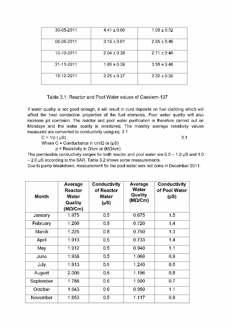
The reactor and pool water measurement are carried out every Monday in order to detect
clad failure as early as possible. It is expected that fission products such as 131-135I, 90Sr, 95Zr, 95Nb, 137Cs, 140Ba, 140La, 85Kr, 133Xe and 135Xe will be transferred through the failed clad to the
reactor. Table 3.1 presents values obtained for the measurements of Caesium-137 in the
reactor and the pool water within the year 2011. The other elements were not detected. The
obtained values for 137Cs are lower than the minimum values stated by the Safety Analysis
Report (SAR). According to the SAR, 3.4 x 10⁵Bq/L of 137Cs in the reactor and pool water
respectively present minimum hazard [14] [15].
Date Reactor Water Pool Water
Activity (Bq/L) Activity (Bq/L)
28-03-2011 3.63 ± 0.51 3.74 ± 0.53
04-04-2011 3.51 ± 0.60 3.40 ± 0.48
18-04-2011 3.51 ± 0.44 2.46 ± 0.46
09-05-2011 2.48 ± 0.44 5.97 ± 0.67
16-05-2011 3.93 ± 0.53 3.86 ± 0.64
30-05-2011 4.41 ± 0.60 1.08 ± 0.32
06-06-2011 3.19 ± 0.67 2.85 ± 0.46
10-10-2011 2.04 ± 0.39 2.71 ± 0.46
21-11-2011 1.86 ± 0.39 3.58 ± 0.46
19-12-2011 2.25 ± 0.37 2.32 ± 0.30
Table 3.1 Reactor and Pool Water values of Caesium-137
If water quality is not good enough, it will result in curd deposits on fuel cladding which will
affect the heat conduction properties of the fuel elements. Poor water quality will also
increase pit corrosion. The reactor and pool water purification is therefore carried out on
Mondays and the water quality is monitored. The monthly average resistivity values
measured are converted to conductivity using eq. 3.1
C = 1/ρ ( µS) 3.1
Where C = Conductance in cm/Ω or (µS)
ρ = Resistivity in Ω/cm or (MΩ/cm)
The permissible conductivity ranges for both reactor and pool water are 0.5 – 1.0 µS and 1.0
– 2.0 µS according to the SAR. Table 3.2 shows some measurements.
Due to pump breakdown, measurement for the pool water was not done in December 2011.
Month
Average
Reactor
Water
Quality
(MΩ/Cm)
Conductivity
of Reactor
Water
(µS)
Average Water
Quality (MΩ/Cm)
Conductivity
of Pool Water
(µS)
January 1.975 0.5 0.675 1.5
February 1.200 0.8 0.720 1.4
March 1.225 0.8 0.750 1.3
April 1.913 0.5 0.733 1.4
May 1.912 0.5 0.940 1.1
June 1.938 0.5 1.068 0.9
July 1.913 0.5 1.240 0.8
August 2.000 0.5 1.196 0.8
September 1.788 0.6 1.500 0.7
October 1.643 0.6 0.950 1.1
November 1.853 0.5 1.117 0.9
December 1.867 0.5 - -
Table 3.2 Reactor and Pool Water Conductivity
4.0 MODIFICATION OF EXISTING COMPONENTS
4.1 Micro Computer Closed Loop System
In GHARR-1, two independent control systems are used to operate the reactor; control
console (CC) and micro-computer closed loop system (MCCLS). Several parts and
components have been replaced, as a result of ageing and obsolescence. The micro-
computer control system was finally replaced with a new one in 2008 with the operating
system changed from Disk Operating System (DOS) to Windows “eXPerience” (Win XP).
The interface board sockets have been changed from Industrial Standard Architecture (ISA)
to Peripheral Component Interconnect (PCI) making the system user friendly. The new
system has been improved based on the original system. Some circuits have been adjusted
and some monitoring parameters added to make the new system perfect. The new version
provides the neutron flux, inlet and outlet temperatures, control rod position, reactor water
and pool water conductivity, pool water temperature, preset options, data analysis tools and
a lot more features that allows for an interactive use of the system. After shutdown, the
operating data are stored in EXCEL SHEET. Figure 4.1 shows the hardware of the computer
control system.

Figure 4.1 Hardware of the computer control system
The cost of the project was borne by the IAEA under REP No. GHA 4012-001-001N/IAEA.
Three experts from China Institute of Atomic Energy (CIAE) were in Ghana for the project.
4.2 Control Rod Drive Mechanism
The control rod drive mechanism was replaced with a newer version in August 2009. The
installation was performed by the staff of GHARR-1. Following procedures approved by the
regulatory authority.

Figure 4.2. Old and New Control Rod Drive Mechanism
New
Old

Figure 4.3. Installation by local team
4.2.1 Activities Carried Out
A. Measurement Procedure
Measurements were made for the new control rod drive mechanism between;
1. The drive wheel and first clamping block
2. The drive wheel and second clamping block
3. The second clamping block and the plumb of the control rod
It was realized that some maintenance work carried out on the old control rod drive
mechanism had altered the length of the wire rope but it still did function normally.
B. Replacement Procedure
1. Radiation monitoring was conducted to ensure health safety of personnel.
2. The old control rod drive mechanism was disengaged and the control rod removed
and allowed to dissipate off its radioactivity in the pool for three days.
3. The whole setup of the new control rod was then placed in the reactor core after all
required measurements had been adhered to and the drive mechanism had been
configured. The drive mechanism was then tested by fixing it on the reactor.

4. On switching the console, the rod position indicator on the console moved to 140 mm
instead of zero. The console was switched off and the two autosyns (the transmitter
and the receiver) were synchronized by readjustment of the dial on the receiver).
5. The console was switched on again and the dial remained at the zero position.
6. The flux build up was then tested for at a preset value of 1×10⁹n/cm2 s. The rod lifted
to 230mm to allow for the flux build-up. On removing the first cadmium capsule, there
was no significant flux build-up. This remained so until the fourth capsule was
removed.
7. After the removal of the cadmium capsules and string from the inner site of the
reactor, the flux build-up was found to be extremely slow. Also, after the completion of
the flux build-up process, the control rod position indicator showed that the control rod
position did not drop but remained at a high value.
8. It was concluded that the length of the rope wire was too long to allow the normal
operation of the control rod drive mechanism. The reactor was shut down again and
the cadmium string and capsules were sent back into the reactor. To determine how
much wire rope was to be removed, the base of the control rod drive mechanism was
packed with 15 mm thick wood while ensuring that the rod was still in its guide and
the reactor was operated. There was a noticeable change in the rate of flux build-up
although it was still too slow. The procedure was repeated with 25mm, 40mm and
finally 70mm thick wood. At 70mm, the rate of flux build up was found to be normal.
9. The necessary adjustments to the wire rope were made (i.e. 70mm of wire rope was
removed) and the control rod drive mechanism was placed on the reactor. The
reactor was operated as usual at 1×10⁹n/cm2s, the cadmium strings and capsules
were removed and the flux build up now appear normal.
10. The reactor was shut down and operated again the next day to ensure that its
operation remained normal.
11. The installation of the new control drive mechanism started on 4th August, 2009 and
completed on the 19th August, 2009.
12. The new dimension set-up of the new control rod drive mechanism was shown in fig
4.2.
Challenges:
It was obvious that the design of the new control rod drive mechanism was different
from the old one. Hence new measurements had to be taken and adjustments made
where necessary.
In doing this, the original design measurements of the old drive mechanism was used
to configure the new one since it did not have any accompanying document to assist
in its installation.
After the detection of the slow build-up of flux, measurements were then taken for the
mass and length of the plumbs of both the new and the old control rod. It was realized
after taking the measurements that, both the length and mass of the plumb of the new

control rod assembly, fell short significantly of the old control rod assembly. The
length of the new plumb was 180mm while that of the old was 218mm. Of much
interest was the mass of the new rod which fell short of the 1kg standard used in
most literature concerning the reactor. Whereas the plumb of the old control rod had
an average mass of 824.48g, the plumb of the new control rod had an average mass
of 640.30g. So we were compelled to use the old plumb to ensure prompt scram of
the reactor.
As a result, the end of the wire rope of the new control rod drive mechanism was
knotted in such a way that it could be accommodated by the old control rod assembly.
All procedures carried out were done with careful adherence to all safety measures
put in place for the particular type of exercise. The new control rod drive mechanism,
has thus, been successfully installed while maintaining the old control rod in the
reactor setup. The measurements taken before and after installation are captured in
table 4.1 below.
Before the Installation
Rise
Time
Falling
Time
Criticality
1x10⁹n/cm2s
Half
Power(15kw)
5x10¹¹n/cm2s
Build-up Time
28
Sec
28 sec 125 mm 154 mm 3 mins 20
Secs
After the Installation
Rise
Time
Falling
Time
Criticality
1x10⁹n/cm2s
Half Power
(15kw)
5x10¹¹n/cm2s
Build-Up Time
26
Sec
26 Sec 130 mm 154 mm 2 mins
Table 4.1 Measurements before and after installation
4.3 CONSTRUCTION OF SLANT TUBE
The existing irradiation sites accommodate only small samples. The guide (slant) tube
enables larger samples to be irradiated and also carry out some experiments owing to its
volume efficiency. The existing two (2) slant tubes developed some holes and were removed.
The guide tube was constructed using aluminium sheet and moulded into a cylindrical tube
and joined together by an electrical welding as shown in fig. 4.4 below.

The tube is 15 cm in diameter and total length of 540 cm. A plunger of aluminum material
was designed and moulded to be plugged into the tube. The dimension of the plunger is 150
cm by 18 cm as shown in fig.4.5 with a special cover 9 cm by 31cm fig. 4.6. Lead was melted
and put in the lower part of the plunger at 20 cm from the bottom likewise the cover also at 3
cm from the top. The lead was used to prevent the possibility of radiation escaping into the
reactor hall during operation.
Fig 4.7 shows the installation of the guide tube on the reactor vessel. The tube was fixed 20
cm from the reactor vessel on a stainless steel plate of the following dimensions: thickness
was 1.5 cm, length 105 cm and the width 33 cm bolted onto the two I-beams stretched over
the pool. The tube was fixed closed to the lower vessel of where the reactor core is seated at
a distance of 5.0 cm.
4.3.1 Experimental Procedure for Guide Tube Installation
The reactor was operated under automatic mode at the neutron flux of 1x10⁹ n/cm2s to obtain
the core excess reactivity. The inlet and the outlet temperatures were recorded at this flux
value. Gamma radiation on top of the reactor was also recoded before the installation as
shown in tables 4.2.
Table 4.2 Parameters recorded at 1x10⁹ n/cm
2s before the installation
Four cadmium rabbits and a string were pumped into the inner irradiation sites to ensure
subcriticality of the reactor.
The slab holding the old guide tube was removed and a new one fixed. The guide tube was
lowered with the help of a 5 tones crane fixed in the reactor hall through 18 cm hole in the
slab and bolted it firm in position.
The cadmium rabbits and the string were pumped out and operated the reactor at the same
neutron flux to ensure the stability of the reactor.
It could be seen from the data shown in table 4.4 that after 18 min of reactor operation when
the slant tube was installed without the insertion of the plunger, there was increase in gamma
dose at the top of the reactor vessel. The gamma dose reduced after the plunger insertion fig.
4.5. This could be attributed to the interaction of air molecules with charge particles in the
slant leading to the emission of radiation.

4.3.2 Financial Support
Financial support for the project was provided by the International Atomic Energy Agency
(IAEA) through the CRP GHA15171
Table 4.3- Parameters recorded at 1x10⁹ n/cm2s after the installation
Table 4.4 Recordings at 5 x 10¹¹ n/cm2s before the insertion of the plunger

Table 4.5 - Recordings after inserting the plunger and operated at 5x10¹¹ n/cm2s

Fig.4.4. Slant tube
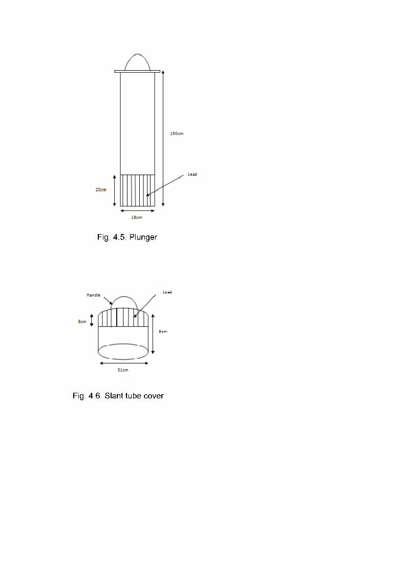
Fig. 4.5. Plunger
Fig. 4.6. Slant tube cover

Figure 4.7. Vertical cross section of the reactor showing the slant tube

4.4 Refurbishment of deionized water plant
The facility is designed for production of pure water (light water) to top up the reactor and the
pool water respectively. The main design parameters to be satisfied for providing quality pure
water for the miniature reactor are:
Water flow rate: 0.5 – 0.7 m3/h
Conductivity ≤ 1µS/cm
pH = 6.0 ± 0.5
The content of ions such as Fe+3, Cu+2, Cl- are less than 0.1 mg /L respectively.
Fig. 4.8 below shows the flow chart for processing of the light water for the miniature reactor.
Fig.4.8. Flow chart of pure water processing
The resins in the plant columns were replaced in December 2012. The pipes and the valves
were also replaced in November 2012 as a result of brittleness due to ageing. The resins
have been regenerated twice, 2005 and 2010. Fig. 4.9 shows the purification system.
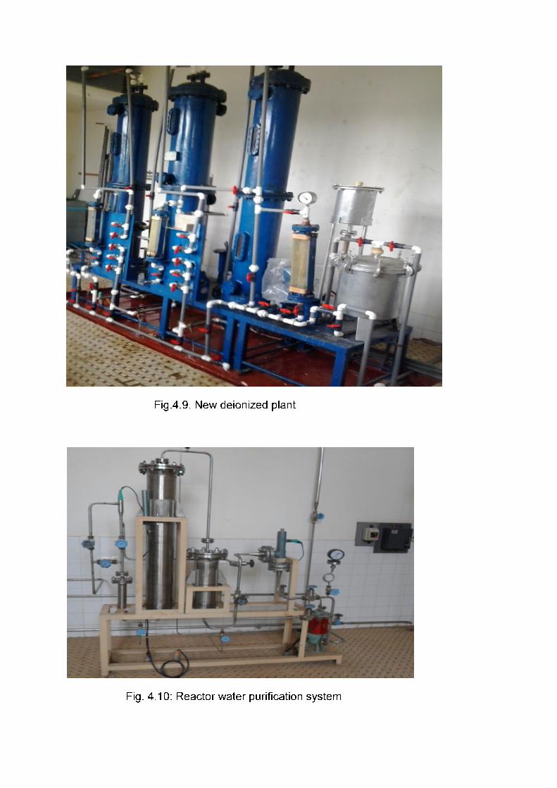
Fig.4.9. New deionized plant
Fig. 4.10: Reactor water purification system

Fig.4.11: Reactor pool water purification system
5.0 DESIGN FEATURES FOR COMPONENT REPLACEMENT
A crane rail runs the large access door over the reactor pool to the roof wall of the reactor
hall. The rail carries a crane of lifting capacity of 5 tons and height 135 cm from the bottom of
the pool. The maximum clearance between the top of the reactor pool and the bottom of the
crane hook is 55 cm. The reactor vessel is in two sections, the upper and the lower section.
The two-section design of the reactor vessel facilitates the installation of the reactor core and
the core replacement after its useful life without any loss of shielding using the crane.
A long handling tool is provided to remove the core and placed in the pool. The same tool is
used to lift the aluminium tray on top of the reactor core for beryllium addition.
Four (4) cadmium capsules of 4 mk worth is provided for shutting down the reactor in the
event of a failure of the control system. This system is not automatically actuated at the onset
of an abnormal condition. Auxiliary shutdown is accomplished by the manual insertion of
cadmium capsules into the inner irradiation sites. To ensure deep subcritical reactivity of the
reactor, additional string of cadmium capsules at the same worth is available to replace the
control rod when failure occurs.
6.0 PERIODIC SAFETY REVIEW FOR GHARR-1
Safety reviews are performed regularly to ensure adherence to regulations governing reactor
systems operation. The Reactor Safety Committee (RSC) as well as the Radiation Safety
Committee (RadSC) perform regular safety reviews and make recommendations to the
Reactor Manager and the Director of NNRI for the necessary actions to be taken.
The RSC has the responsibility to review: experiments, modification, procedures, reportable
occurrences and personnel qualification. Review of safety documents are conducted every
two (2) years prior to the safety analysis report (SAR) which is reviewed every five (5) years.

Feedback from previous safety review mission and operational experience, expert missions’
recommendation and documents developed by the reactor manager and team assist in the
review for onward submission to the regulatory agency for approval.
Modifications and experiments having significance effect on safety are reviewed by the
reactor safety committee and recommendations made to the reactor manager for review
before submission to the regulatory body for further review and approval.
7.0 AGEING OF STAFF / SUCCESSION PLAN
In accordance with Article 3 of Act (2000) which mandates the Commission to collaborate
with the Universities in training and teaching in the field of nuclear energy, Ghana Atomic
Energy commission (GAEC) with the University of Ghana and IAEA has established a
Postgraduate School of Nuclear and Allied Sciences (SNAS) to train personnel for Ghana’s
nuclear practice and the Africa Region. The objectives are to preserve and enhance
knowledge in nuclear technology and to develop human and institutional capacity in the field
of nuclear and allied sciences. The following M.Phil. and Ph.D Courses are offered: Nuclear
Engineering, Applied Nuclear Physics, Nuclear and Environmental Protection, Radiation
Protection, Nuclear Agriculture, Medical Physics, Nuclear and Radiochemistry among others.
Sustainable Human Resource Development (HRD) is assured.
8.0 CONCLUSION
In the eighteen (18) years of operating the GHARR-1, maintenance and safety practices
have helped to reduce the effect of ageing on the operation of the reactor. Preventive and
corrective maintenance of Safety Systems and Components (SSCs) is done according to
written procedures, which have been reviewed and recommended by the RSC. The
successful operation of GHARR-1 facility has largely depended on the management
structure, safety and operational documents which are mostly based on the IAEA standards
and experts’ recommendations. Special precautions are taken such that materials that may
have enhanced corrosive properties such as (e.g. mercury, rhenium, and magnesium) are
not irradiated.
Acknowledgements
The authors express our appreciation to the International Atomic Energy Agency for
providing the platform for the discussion on ageing management at the various research
reactor centres in the world. One such event led to the preparation of this document.

References
[1] AKAHO, E. H. K., ANIM-SAMPONG, S., DODOO-AMOO, D. N. A., MAAKUU, B. T., EMI-
REYNOLDS, G., OSAE, E. K., BOADU, H. O., BAMFORD, S. A., Safety Analysis Report for
Ghana Research Reactor – 1, GAEC-NNRI-RT-26, March 1995.
[2] AKAHO, E. H. K., MAAKUU, B. T., Simulation of Reactivity Transients in a Miniature
Neutron Source Reactor Core, Nuclear Engineering and Design, 213, 2002, 31 – 42.
[3] CHENGZHAN, G., HANMING, H., ZHIYI, H., SHUANKAI, S., Prototype MNSR, Dynamic
Feedback Experiments and Calculations, China Institute of Atomic Energy Technical Report,
Beijing, China, 1985.
[4] UNITED STATES CONGRESS, Office of Technology Assessment, Aging Nuclear Power
Plants: Managing Plant Life and Decommissioning, OTA-E-575, 1993, pp. 37-58.
[5] GHANA ATOMIC ENERGY COMMISSION, Ghana Atomic Energy Commission at a
Glance, Fifth edition (revised), 2006, p. 1.
[6] GAO JIJIN, General Description of Ghana Miniature Neutron Source Reactor, China
Institute of Atomic Energy (CIAE), 1993.
[7] S. K. A. ABOAGYE, Maintenance and Quality Assurance Program, Ghana Research
Reactor-1, NNRI, GAEC, GHARR-1/QA-MP-01, 1995, pp. 1-8.
[8] MAAKU, B. T., AKAHO, E. H. K., Report on Top Beryllium Plate Addition to GHARR-1
Core, Technical Report, National Nuclear Research Institute, GAEC, GHARR-1/OPB/01,
2002.
[9] S., NOVAK, M., PODEST, Nuclear power plant ageing and life extension: Safety aspects,
An overview of issues and the IAEA’s symposium, IAEA Bulletin, 4/1987, 1987, pp. 31-33.
[10] INTERNATIONAL ATOMIC ENERGY AGENCY, Regional Workshop on Review and
Assessment of Research Reactor Safety Documents for African Countries, National Nuclear
Research Institute, Ghana Atomic Energy Commission, 2008.
[11] INTERNATIONAL ATOMIC ENERGY AGENCY, Follow-Up Integrated Safety
Assessment of Research Reactors (Follow-Up INSAAR) Mission to the Ghana Research
Reactor-1, Accra, 2009.
[12] TANG DAOZHU, ZHENG YANWEI, GAO JIJIN, CHEN SHUPING, Deionized Water
Supply System, China Institute of Atomic Energy (CIAE), 1993.
[13] INTERNATIONAL ATOMIC ENERGY AGENCY, IAEA Safety Standards Series No.
SSG-10, Ageing Management for Research Reactors, Specific Safety Guide, 2010.
[14] J.K. GBADAGO, M.A. ADDO. E.O. AMPONSAH-ABU, N.S. OPATA, I.ENNISON, A.G.
AMPONG, K.GYAMFI, I.BAIDOO, Annual Operating Technical Report, Nuclear Reactors
Research Centre, National Nuclear Research Institute, Ghana Atomic Energy Commission,
2011.
[15] SAR, Safety Analysis Report for GHARR-1, GAEC-NNRI-RT-26, MARCH-1995.