afh 10-222, volume 5 guide to contingency electrical power
TRANSCRIPT

GUIDE TO CONTINGENCY ELECTRICAL POWER
SYSTEM INSTALLATION
AIR FORCE HANDBOOK 10-222, VOLUME 5 1 JULY 2008
Incorporating Change 1, 15 September 2008
DEPARTMENT OF THE AIR FORCE

BY ORDER OF THE AIR FORCE HANDBOOK 10-222, VOLUME 5 SECRETARY OF THE AIR FORCE 1 July 2008
Incorporating Change 1, 15 September 2008
Operations
GUIDE TO CONTINGENCY ELECTRICAL POWER
SYSTEM INSTALLATION
ACCESSIBILITY: Publications and forms are available on the e-Publishing
website at www.e-publishing.af.mil for downloading or ordering.
RELEASABILITY: No releasability restrictions on this publication.
OPR: HQ AFCESA/CEXX Certified by: HQ USAF/A7CX
Supersedes AFH 10-222V5, (Col Donald L. Gleason)
1 October 1998; Pages: 142
AFH 10-222V10,
1 May 2000
This handbook addresses actions necessary to install contingency electrical
generation and distribution systems equipment found in the Basic Expeditio-
nary Airfield Resources (BEAR) equipment sets, including legacy systems
that may have been transitioned into the BEAR program to support austere
base force deployments. This handbook applies to Electrical Systems and
Electrical Power Production technicians charged with providing power gen-
eration and electrical distribution systems support for contingency bed-
downs, including Air National Guard (ANG) units and Air Force Reserve
Command (AFRC). Readiness and deployment planners and base level mo-
bility team chiefs responsible for contingency planning should also use it for
information regarding siting issues and requirements. This guide may also be
used in support of peacetime contingencies. The electrical and power pro-
duction technicians using this handbook should have a basic knowledge of
electrical components of the contingency systems. At least one craftsman in
each specialty will be task certified for directing and meeting the installation,
Certified Current, 7 July 2011

AFH 10-222 Volume 5 1 July 2008 2
operation, and maintenance requirements for the applicable components of
the system. Other users of this handbook should be familiar with basic con-
tingency electrical components. Guidance in this handbook is based on the
references listed in Attachment 1. Refer recommended changes and ques-
tions about this publication to the Office of Primary Responsibility (OPR)
using AF IMT 847, Recommendation for Change of Publication; route AF
IMT 847s from the field through Major Command (MAJCOM) publica-
tions/forms managers. Ensure that all records created as a result of processes
prescribed in this publication are maintained in accordance with AFMAN
37-123 (will convert to AFMAN 33-363), Management of Records, and dis-
posed of in accordance with the Air Force Records Disposition Schedule
(RDS) located at https://afrims.amc.af.mil/. The use of the name or mark of
any specific manufacturer, commercial product, commodity, or service in
this publication does not imply endorsement by the Air Force.
SUMMARY OF CHANGES
This publication has been substantially revised and must be completely re-
viewed. This version consolidates and supersedes AFH 10-222 Volumes 5
and 10 and implements BEAR as the sole Air Force contingency electrical
system superseding legacy Harvest Falcon and Harvest Eagle systems. The
remaining Falcon and Eagle components will transition into the BEAR sys-
tems and will therefore also be described in this revision. The great majority
of system components are installed identically with the exception of the pri-
mary distribution and switching centers. Major changes include: consolidat-
ing the contingency power plant with the electrical distribution system. It
adds the BEAR components of the Deployable Power Generation and Distri-
bution System, the Primary Switch Center (PSC) being the biggest change.
Change 1 corrects the discrepancies in paragraph 5.10.2 and Figure 5.26 by
emphasizing that proper personal protective equipment must be worn when
disconnecting energized arc strangler switches. It also adds Chapter 6, In-
formation Collection, Records, and Forms. A margin bar ( ) indicates newly
revised material

AFH 10-222 Volume 5 1 July 2008 3
Chapter 1 – INTRODUCTION 9
1.1. Contingency Electrical System Overview ........................... 9
1.2. Deployment Packages .......................................................... 10
Figure 1.1. Force Module Construct ………………………………….. 10
Table 1.1. BEAR Electrical Equipment by UTC ................................. 12
Chapter 2 – MAJOR SYSTEM COMPONENTS 13
2.1. Deployable Power Generation and Distribution
System (DPGDS) ................................................................ 13
Figure 2.1. MEP-12A Generator .......................................................... 13
Figure 2.2. Primary Switch Center (PSC) ............................................ 15
Figure 2.3. Secondary Distribution Center (SDC),
Low-Voltage Side ............................................................... 17
Figure 2.4. Power Distribution Panels (PDP) ...................................... 18
Figure 2.5. RALS Container and Light Poles ...................................... 19
Figure 2.6. Tactical Quiet Generators .................................................. 19
Figure 2.7. Cable Reel Pallet Assembly (CRPA) ................................ 20
2.2. Legacy Equipment ............................................................. 21
Figure 2.8. MEP-005 Generator ........................................................ 21
Figure 2.9. MEP-006 Generator ........................................................ 21
Figure 2.10. MEP-007 Generator ........................................................ 22
Figure 2.11. Primary Distribution Center ............................................ 23
Figure 2.12. Load Break Elbow (secured with Grip-All clamp stick) . 23
Figure 2.13. Secondary Distribution Center ........................................ 24
Figure 2.14. Mission Essential Generator Connected to SDC ............. 25
Figure 2.15. Low-Voltage Cables with Cannon Plug Connections ..... 25
Figure 2.16. Typical Power Distribution Panels ................................. 26
Figure 2.17. Equipment Rack with Generator Control Panels ........... 27
Figure 2.18. Typical (22x22) Fuel Bladder ........................................ 28
Figure 2.19. Fuel Manifold ................................................................. 28

AFH 10-222 Volume 5 1 July 2008 4
2.3. System Composition ......................................................... 29
Figure 2.20. Basic Electrical Distribution System Schematic ........... 30
Chapter 3 – SITE PLANNING AND LAYOUT 31
3.1. Siting ................................................................................ 31
Figure 3.1. Dispersal Patterns for 3-, 6-, 9-, and 12-Facility
Groupings ........................................................................ 32
Figure 3.2. SDC Placement for Non-Dispersed 24-Facility
Grouping .......................................................................... 32
Figure 3.3. Insufficient No. of SDCs for Dispersed 24-Facility
Grouping .......................................................................... 33
Figure 3.4. Five SDCs Supporting Dispersed 24-Facility Grouping ...... 33
3.2. Site Planning .................................................................... 34
3.3. Layout .............................................................................. 39
Figure 3.5. Linear Base Layout ......................................................... 39
Figure 3.6. 1,100-Person Radial Electrical Distribution System ...... 40
Figure 3.7. Conventional Type Base Layout .................................... 40
Figure 3.8. 1,100-Person Looped Electrical Distribution System .... 41
Figure 3.9. 1,100-Person Interconnected Electrical Distribution
System ............................................................................ 42
Figure 3.10. Critical Facility SDCs Connected By Parked Cables ...... 42
Table 3.1. 1,100-Person Facility List ................................................ 43
Table 3.2. 3,300-Person Facility List ................................................ 44
Table 3.3. General Separation Distances for Facilities in Groups .... 45
Figure 3.11. Typical 1,100-Person Layout with Major Roadway
Grid ................................................................................. 47
Figure 3.12. Typical Growth from 1,100- to 3,300-Person Layout .... 48
3.4. Electrical Planning ............................................................ 49
Table 3.4. Typical Harvest Falcon Demand Factors ........................ 50
Table 3.5. Typical Harvest Falcon Electrical Planning Factors ....... 51

AFH 10-222 Volume 5 1 July 2008 5
Table 3.6. Example Wing Ops Group Secondary Distribution
Schedule .......................................................................... 55
Table 3.7. Example Wing Operations Group SDC Feeder
Schedule .......................................................................... 57
Figure 3.13. Example SDC Circuit for Wing Operations Group ....... 59
Figure 3.14. Typical Connection between Two PDCs ....................... 61
Figure 3.15. Parked Cables between Two SDCs on Different
Circuits ........................................................................... 62
Figure 3.16. Rerouting Cables to Prevent PDC Overloading ............. 63
Chapter 4 – INSTALLATION 65
4.1. Safety Summary ................................................................ 65
4.2. Personnel Responsibilities ................................................ 67
Table 4.1. Task Responsibilities ...................................................... 68
4.3. Grounding ......................................................................... 68
Figure 4.1. Typical Equipment Horizontal Ground Rod Installation . 69
Figure 4.2. Typical Equipment Laced Wire Grounding Installation .. 70
Figure 4.3. Typical Equipment Grounding Grid Platform Installation 70
4.4. DPDGS High-Voltage Component Installation ................ 71
Figure 4.4. SDC Ground Rod Assembly ............................................. 72
Figure 4.5. Grounding Location on the SDC ....................................... 73
4.5. HARVEST Series High-Voltage Component Installation . 73
4.6. Laying Out High-Voltage Cable ........................................ 74
Figure 4.6. Primary Cable Cross-section ............................................. 74
4.7. Trenching ........................................................................... 75
Figure 4.7. Tractor with Backhoe, Blade, and Trenching Wheel ........ 76
Figure 4.8. Trench and Cable Detail ................................................... 77
Figure 4.9. Multiple Cable Runs in Common Trench ......................... 78
4.8. Fabrication for Load Break Elbows ................................... 78
4.9. Cable Connections from Generators to PSC/PDC ............. 78

AFH 10-222 Volume 5 1 July 2008 6
Figure 4.10. Feeder Circuits Labeled ……………………………….. 79
4.10. Connections from SDCs to PSC/PDC ............................. 80
Figure 4.11. Detail of Electric Fusible Disconnect (EFD) .................... 81
Figure 4.12. Disconnecting EFD Center Pole with a Switch Stick ..... 81
Figure 4.13. SDC Input Ground Connection ...................................... 82
Figure 4.14. Cables Connected to Input Bushings .............................. 83
Figure 4.15. SDC Input and Output Cables ........................................ 84
Figure 4.16. Branch Connected SDCs with a MEP-12A Generator ... 85
4.11. Connections from SDCs to PDPs and Service Panels .... 85
Figure 4.17. Connection from SDC to Small Shelter System PDP .... 86
Figure 4.18. Cannon Plug Connection from SDC to ESC Service
Panel ............................................................................... 86
Figure 4.19. Cannon Plug Connection from PDP to ECU .................. 87
4.12. Mission Essential Power (MEP) ..................................... 88
Figure 4.20. SDC Secondary Connection Panel and Circuit
Breakers .......................................................................... 89
Chapter 5 – POWER PLANT LAYOUT 91
5.1. Introduction ........................................................................ 91
5.2. Site Selection ...................................................................... 91
5.3. Equipment Layout .............................................................. 93
Figure 5.1. Two Unit Plant w/PSC Configuration .................................. 94
Figure 5.2. Three-Unit Plant w/PSC Configuration ................................ 94
Figure 5.3. Four-Unit Plant w/PSC Configuration ............................... 95
Figure 5.4. Four-Unit Plant w/PDC Configuration .............................. 96
Figure 5.5. General Plant Configurations w/PDCs by Population ..... 96
5.4. Generator Installation ......................................................... 97
Figure 5.6. Generators Positioned w/Radiators Downwind .............. 97
Figure 5.7. Ground Stud on MEP-12A Generator ............................. 98
5.5. Establish Fuel Storage Manifold System ......................... 98

AFH 10-222 Volume 5 1 July 2008 7
Figure 5.8. 20,000-Gallon Fuel Bladder Assembly .......................... 99
Figure 5.9. DPGDS External Fuel Supply Layout ............................. 100
Figure 5.10. Fuel Hose Connected to MEP-12A ............................... 100
Figure 5.11. Manifold Assembly ....................................................... 101
Figure 5.12. Typical Fuel Bladder Placement ................................... 102
Figure 5.13. Bladder and Berm Detail .............................................. 104
5.6. PSC Installation ............................................................... 105
5.7. PDC Installation .............................................................. 105
Figure 5.14. PDC Site Requirements ................................................ 106
Figure 5.15. Typical PDC Clearances ............................................... 107
Figure 5.16. Placement of PDC near Generators .............................. 107
Figure 5.17. Grounding Locations on the PDC ................................. 108
5.8. Cable Connections ........................................................... 108
Figure 5.18. Power Panel Box ........................................................... 110
Figure 5.19. Connecting Cables to MEP-12A with Grip-All Clamp
Stick ................................................................................................... 111
Figure 5.20. Grounding Brackets ......................................................... 112
Figure 5.21. PDC Cable Approach Plan .............................................. 113
Figure 5.22. Ground Stud at Input Connection ................................... 114
Figure 5.23. PDC Line Side Connection ............................................. 115
Figure 5.24. PDC Output Feeder Connection ..................................... 115
Figure 5.25. Arc Strangler Switches Removed from Unused Feeder . 116
5.9. PDC Installation Checkout ................................................ 116
Table 5.1. PDC Installation Checkout ................................................. 117
5.10. Energized PDC Emergency Disconnect ......................... 117
Figure 5.26. Disconnecting the Arc Strangler Switches ..................... 118
Figure 5.26a. Disconnecting Phase B Arc Strangler Switch ………. 119
5.11. Remote Generator Operation .......................................... 119

AFH 10-222 Volume 5 1 July 2008 8
Figure 5.27. MEP-12A Control Panel ............................................... 119
Figure 5.28. Power Plant Control Room (ESC) ................................ 120
Figure 5.29. Control Cables .............................................................. 120
Figure 5.30. Control Cable Connected at MEP-12A ......................... 121
5.12. Connections Between Plants ............................................. 121
5.13. Remote Area Lighting System (RALS) ........................... 121
5.14. Contingency Electrical System Checklist ........................ 122
5.15. Prescribed and Adopted Forms ........................................ 122
Chapter 6 – INFORMATION COLLECTION, RECORDS,
AND FORMS 123
6.1. Information Collections …………………………………. 123
6.2. Records ………………………………………………….. 123
Attachment 1— GLOSSARY OF REFERENCES AND
SUPPORTING INFORMATION 124
Attachment 2—LOAD BREAK ELBOW GENERAL ASSEMBLY
INSTRUCTIONS 127
Attachment 3—CONTINGENCY ELECTRICAL SYSTEM
INSTALLATION CHECKLIST 141

AFH 10-222 Volume 5 1 July 2008 9
Chapter 1
INTRODUCTION
1.1. Contingency Electrical System Overview. The contingency electrical
system is composed of three major components: generation, high-voltage
primary (4,160-volt) distribution, and low-voltage secondary (120/208-volt)
distribution. The equipment as described in this handbook must be installed,
operated, and maintained by qualified persons who are knowledgeable in the
installation, operation, and maintenance of electric power generation and
distribution equipment and their associated hazards.
Note: Electricians and maintenance personnel shall wear appropriate person-
al protective equipment (PPE), to include arc thermal performance value
(ATPV) rated PPE, in accordance with AFI 32-1064, Electrical Safe Prac-
tices, and UFC 3-560-01, Electrical Safety, O&M, prior to working on or
near energized electrical equipment or circuits. BCE or commander approval
is needed prior to working on any energized circuits.
1.1.1. Within the major components are subcomponents such as generators,
primary cable reels and pallets, secondary distribution centers (SDCs), pri-
mary distribution centers (PDCs), primary switch centers (PSC), remote area
lighting system (RALS), secondary cable assemblies, power distribution
panels, and mission essential power (MEP) cable assemblies.
1.1.2. Contingency electrical systems arrive at the beddown site in air trans-
portable deployment packages consisting of tents or small shelter systems
(SSS); medium-type shelters that could include frame supported tension fa-
bric shelters (FSTFS), dome shelters, or medium shelter systems (MSS);
hardwall shelters; expandable shelter containers (ESC); equipment; and utili-
ty systems and components. These deployment packages are Force Module
enablers necessary to open and operate any austere airbase across the spec-
trum of Air and Space Expeditionary Force (AEF) operations. In addition,
these packages may be used for other contingencies such as humanitarian
operations.

AFH 10-222 Volume 5 1 July 2008 10
1.2. Deployment Packages. Deployment packages have transitioned from
the legacy Harvest series to the Basic Expeditionary Airfield Resources
(BEAR) program. Force Modules are building blocks for BEAR capabilities
(Figure 1.1). They focus on the number of austere airfields required to sup-
port the spectrum of operations in place of the previous concept that was
based on number of troops and aircraft supported. Buildup of the airbase
using newly configured BEAR Force Module Unit Type Codes (UTCs) en-
sures the airbase is ready to receive the forces and generate the mission.
BEAR, as a component of Agile Combat Support (ACS), enables the Air
Force to deploy and sustain AEFs at austere locations. In simple terms,
BEAR provides vital equipment, facilities and supplies necessary to bed-
down and support combat forces at expeditionary airbases with limited infra-
structure and support facilities. As a minimum, the beddown location must
have a runway and parking ramp suitable for the type of aircraft deployed
and a source of water that can be made potable.
Figure 1.1. Force Module Construct.
1.2.1. The primary mission of BEAR is to provide expeditionary basing as-
sets for use at austere airfields, thereby providing the AEF with global bas-
ing capability. BEAR is included in the Force Modules that open, establish

AFH 10-222 Volume 5 1 July 2008 11
and operate the base. BEAR supports the full range of Department of De-
fense (DOD) missions within our National Military Strategy (NMS).
1.2.2. BEAR equipment is made up of seven equipment component sub-
systems; shelters, environmental control, power, waste/water, hygiene, feed-
ing, and airfield support. These sub-systems are contained in BEAR sub-sets
which include BEAR 150 (B-150) sets, BEAR 550 Initial Housekeeping (B-
550i) sets, BEAR 550 Follow-on Housekeeping (B-550f) sets, BEAR Indus-
trial Operations (B-IO) sets, BEAR Initial Flightline (B-IF) sets, and BEAR
Flightline Follow-on (B-FF) sets.
1.2.3. Legacy systems include Harvest Eagle (HE) and Harvest Falcon (HF)
assets.
1.2.3.1. HE sets were air-transportable packages of housekeeping equipment,
spare parts and supplies required to support up to 550 personnel in bare-base
conditions. Typical equipment included billeting tents, kitchens, showers,
latrines, and power and water systems. Tailored 550 (T-550) sets were mod-
ified HE sets providing similar housekeeping capabilities in the PACAF area
of responsibility (AOR).
1.2.3.2. HF housekeeping sets were air-transportable packages of equipment,
spare parts and supplies needed to support up to 1100 personnel in bare base
conditions, principally in the CENTAF AOR. As in HE, typical equipment
included billeting tents, kitchens, showers, latrines, and power and water
systems. Air conditioners were also included for environmental control. HF
also included industrial operations (IOP) and initial and follow-on flightline
(IF and FF) support sets of hard wall shelters, tents, and related civil engi-
neering and logistics equipment needed to maintain a bare base and support
flight operations and maintenance.
1.2.4. BEAR systems employ essentially the same equipment as the legacy
sets did, but configured to better support AF force modules and AETF opera-
tions. Legacy sets are being reconfigured to BEAR sets as the BEAR system
matures. See AFH 10-222V2, Guide to Bare Base Assets, for a complete

AFH 10-222 Volume 5 1 July 2008 12
description of current Unit Type Codes. Table 1.1 lists the electrical equip-
ment contained in the BEAR UTCs.
Table 1.1. BEAR Electrical Equipment by UTC.
B-1
50
B-5
50i
B-5
50f
B-F
I
B-F
F
B-I
O
Pla
yb
oo
k
Op
tio
ns
MEP-12A 2 2 2
MEP-806 4 3 2 2
MEP-805 2 1
PSC/PDC 1 1 1
SDC 10 6 8 2 5 2
PDP – 60kW 4 4
PDP – 25 kW 16 55 52 22 3 23
RALS 2 2 1
CRPA 2 2 2
10K Bladder 2 2 2
Note: Items and quantities are subject to change without notice.

AFH 10-222 Volume 5 1 July 2008 13
Chapter 2
MAJOR SYSTEM COMPONENTS
2.1. Deployable Power Generation and Distribution System (DPGDS).
The DPGDS provides electrical power generation and distribution equipment
that is designed to support austere base prime power requirements. The
DPGDS design is modular, providing the capability to support a broad range
of contingency operations that require electrical power. Contingency opera-
tions ranging in size from relatively small deployments requiring power gen-
eration and distribution at the hundreds of kilowatt level to very large
operations requiring power generation at the multi megawatt level can be
supported using DPGDS equipment. A brief description of the DPGDS ma-
jor components follows.
2.1.1. MEP-12A. Until a reliable prime power generator is procured,
DPGDS will continue to use the legacy primary power source, the MEP-12A
(Figure 2.1). This generator set is a trailer-mounted diesel engine-driven,
prime power (Type II), utility (class 2A), mode I unit that produces 750 kW
at 60 Hz and 625 kW at 50 Hz with 0.8 power factor, lagging. It provides
2400/4160 volts, 3 phase, 4-wire, wye (2400 volts line-to-neutral; 4160 volts
line-to-line) for 60 Hz operation; and 2200-3800 volts, 3 phase, 4-wire, wye
(2200 volts line-to-neutral; 3800 volts line-to-line) for 50 Hz operation.
Figure 2.1. MEP-12A Generator.

AFH 10-222 Volume 5 1 July 2008 14
2.1.1.1. The main control panel assembly allows local and remote start, stop,
monitor, and control of the generator set in operation. Operation can be
achieved up to 150 feet (45 meters) from the generator set.
2.1.1.2. There are two MEP-12A manufacturers, Fermont and MCII. MCII
units start with serial number AW00001. See Appendix D in the T.O. for
differences between the models. The use of the commercial manual shall be
used for maintenance on the KT38 engine, the MCII units, serial number
AW00001 and subsequent (see Appendix A of the T.O.).
2.1.1.3. The MEP-12A is designed to operate on a variety of fuels, which
include DF-2, JP-4, JP-8 DFA (Arctic Grade Diesel), and commercial jet A-
1. One MEP-12A consumes 55 gallons of fuel per hour at full load under
normal environmental conditions, which equates to a consumption of about
1,320 gallons during daily operation. To ensure an adequate continuous fuel
supply, connections are provided to accept fuel from two external fuel
sources, such as a fuel trailer or a fuel bladder.
2.1.1.4. MEP-12A tow vehicles must be rated for a 25,000 pound towing
capacity and have a pintal-hook. One MEP-12A completely fills a C-130
cargo aircraft.
2.1.2. Primary Switching Center (PSC). The Primary Switching Center
(PSC) provides for interconnection and safe isolation of MEP-12A Genera-
tors and the connection of loads to the system (Figure 2.2). The basic elec-
trical component of the PSC is the S&C VistaTM
Switchgear. The S&C
Switchgear is housed in an enclosure that provides both environmental pro-
tection as well as a stacking capability for transportation. The housed
switchgear is referred to as a Primary Switch (PS). When used in conjunc-
tion with DPGDS applications, a PSC is comprised of a minimum of one PS,
up to a maximum of two PSs.

AFH 10-222 Volume 5 1 July 2008 15
Figure 2.2. Primary Switch Center (PSC).
2.1.2.1. General Description. The Primary Switching Center (PSC) features
load-interrupter switches for switching 600-ampere main feeders, and micro-
processor controlled, re-settable, vacuum fault interrupters for switching and
protection of 600-ampere main feeders. These elbow-connected components
are enclosed in an SF6-insulated, welded steel tank. The three position
(closed-open-grounded) load-interrupter switches are manually operated and
provide three-pole live switching of 600-ampere three phase circuits. These
circuits also provide a visible gap when open and internal grounding for all
three phases. The 600-ampere fault interrupters feature re-settable vacuum
interrupters in series with manually operated three-position (closed-open-
grounded) disconnects for isolation and internal grounding of each phase.

AFH 10-222 Volume 5 1 July 2008 16
Fault interrupters provide three-pole live switching of load circuits. Fault
interruption is initiated by a programmable over current control. The Tech-
nical Order contains instructions on programming the control. All routine
operating tasks, switching, voltage testing, and grounding must be ac-
accomplished by a two-person team due to potential exposure of high-
voltage. Cable testing for faults can be performed through the back of the
dead break elbow with insert or feed-thru busing insert, thereby eliminating
the need for cable handling or parking stands.
Note: PSCs are shipped with 600-amp deadbreak connections. A 600-amp to
200-amp adapter must be used prior to putting PSCs into service.
2.1.2.2. PSC Connections. The Primary Switch features six Way Switches
and provides for 3 phase inputs from a MEP-12A Power Unit. Primary pow-
er (4160VAC, 60HZ, or 3800VAC, 50HZ, 3-phase, 3 wire) is supplied to the
PSC via three primary cables. A primary power connection is accomplished
by connecting three loadbreak elbows to the 600-amp-to-200-amp adapters
that are connected to the PSCs bushing wells. The bushing wells are con-
nected to the Way Switches, or ―Ways.‖ The function of each way is either a
switch or a combination of a switch and a circuit breaker. A Load Interrupter
Switch is comprised of only a switch. A Fault Interrupter Switch is com-
prised of a switch and a circuit breaker. Way 1 and Way 2 are Load Interrup-
ter Switches; Way 3, 4, 5 and 6 are Fault Interrupter Switches. Depending on
the configuration of a specific application, the Way Switches can either be
inputs from a MEP-12A, or outputs (feeders) to a load such as an SDC or to
another PSC.
2.1.2.3. Overcurrent Relay Settings. An Operator‘s Remote Terminal (ORT)
and overcurrent control adapter cable is furnished with the PSC to input set-
tings, review settings, and interrogate the event recorder. However, the soft-
ware for programming the overcurrent control is contained within the
control, allowing any computer meeting minimum system requirements to
input settings as long as the adapter cable is available. Two data ports are
provided—one on the enclosure for programming in the field, and another on
the electronics module for programming in the shop. Procedures for pro-

AFH 10-222 Volume 5 1 July 2008 17
gramming overcurrent controls are presented in T.O. 35F14-1-1, Attachment
3, Instruction Sheet 681-515, Instructions for Programming S&C Overcur-
rent Control.
2.1.3. Secondary Distribution Center. The SDC features a 150-KVA three-
phase 2400/4160 VAC primary 120/208 VAC secondary utility transformer
and a low-voltage secondary distribution panel. The SDC has 16 secondary
outputs, 60 amps each (Figure 2.3), which are fed by 100 amp, 208 VAC
output circuit breakers (16 each). The primary power terminals are confi-
gured for a loop through double feed configuration. The high-voltage power
is connected using 200 amp load break quick disconnects, to a common
high-voltage bus. The high-voltage bus is designed to accept one input and
two outputs and is equipped with three sets of high-voltage disconnects. Two
sets of disconnects are used to provide flow through capability. The third set
are fused disconnects and provide overcurrent protection to the high-voltage
side of the transformer. The low-voltage power distribution portion of the
SDC provides 120/208 VAC, 60 HZ, 3-phase, wye connected with ground (5
wire system) from a 3-Phase 800 Amp distribution panel. Note: The SDCs
are available with both the ―Commercial Connector‖ and the ―Class L Con-
nectors.‖ AF SDCs only come with Class-L connectors and will be the only
ones discussed in this handbook.
Figure 2.3. Secondary Distribution Center (SDC), Low-Voltage Side.

AFH 10-222 Volume 5 1 July 2008 18
2.1.4. Power Distribution Panel (PDP). PDPs receive power from SDCs and
distribute it directly to both single and three phase loads. The DPGDS fea-
tures four types of PDPs: 15kW, 25kW, 35kW and 60kW (Figure 2.4). Each
PDP receives 120/208V, 3-phase, 60Hz, wye-connected 4-wire with ground
power through a Class L (MIL-C-22992) connector and distributes to 3-
phase Class L outputs, single-phase military standard outputs, and single-
phase NEMA L5-20R outputs. All outputs are circuit breaker protected.
Figure 2.4. Power Distribution Panels (PDP).
2.1.5. Remote Area Lighting System (RALS). The RALS provides a flexible
solution to support illumination requirements. The RALS features 13 teles-
coping poles, twelve of which are positional through the use of ―left-side‖
and ―right-side‖ cable loop assemblies emanating from the RALS container.
The 13th
pole is mounted on the RALS container. Each RALS pole uses a
single 150 watt, 16,000 lumen high-pressure sodium (HPS) lamp. The ma-
nual telescoping poles are aluminum and have locking collars. Each cable
loop assembly is comprised of two (2) RALS loop cord sections of 375 feet
each, thereby providing 750-foot of lighting string in each direction, for a
total of 1,500 feet. Figure 2.5 illustrates the RALS container and a repre-
sentative pole.

AFH 10-222 Volume 5 1 July 2008 19
Figure 2.5. RALS Container and Light Poles.
2.1.6. External Fuel System. Major components of the External Fuel System
(EFS) are the manifolds, fuel lines, the 20,000 gallon fuel bladder and the
Berm Liner.
2.1.7. Tactical Quiet Generators (TQG). Mission critical loads are supported
with the following generators: six 15kW, four 30kW, and three 60kW TQG
sets (Figure 2.6). Wheel kits are provided to allow ease of transport.
Figure 2.6. Tactical Quiet Generators.
2.1.7.1. MEP-804A. This generator is a diesel or JP-8 powered, mobile unit
that provides 3-phase, 60 cycle, 120/208- or 240/416-volt power to support
loads up to 15 kW. This generator may also be operated at 50 cycles, but will
be derated to 12.5 kW.

AFH 10-222 Volume 5 1 July 2008 20
2.1.7.2. MEP-805A. This is a diesel or JP-8 powered, mobile unit that pro-
vides 3-phase, 60 cycle, 120/208- or 240/416-volt power to support loads up
to 30 kW. This generator may also be operated at 50 cycles, but will be de-
rated to 25 kW. The MEP-805B model is provided with digital controls and
instruments.
2.1.7.3. MEP-806A. This is a diesel or JP-8 powered, mobile unit that pro-
vides 3-phase, 60 cycle, 120/208- or 240/416-volt power to support loads up
to 60 kW. This generator may also be operated at 50 cycles, but will be de-
rated to 50 kW. The MEP-806B model is provided with digital controls and
instruments.
2.1.8. Primary Power Cable. The 1/0, 200A cable provides the tie connec-
tions between the MEP-12A generators and the PSC/PDC, and is also used
for power distribution. The primary cable uses load break elbows as primary
connectors.
2.1.9. Secondary Power Cable. Secondary Power Cable connectors are Class
L connectors and are keyed for voltage, frequency, and current. Covers, ca-
ble grips, and glands for both ends of the cable are supplied and properly
secured to each connector.
2.1.10. Cable Reel Pallet Assembly. DPGDS primary cable is provided on
three cables reels housed within a cable reel pallet (Figure 2.7).
Figure 2.7. Cable Reel Pallet Assembly (CRPA).
AFH 10-222 Volume 5 1 July 2008 21
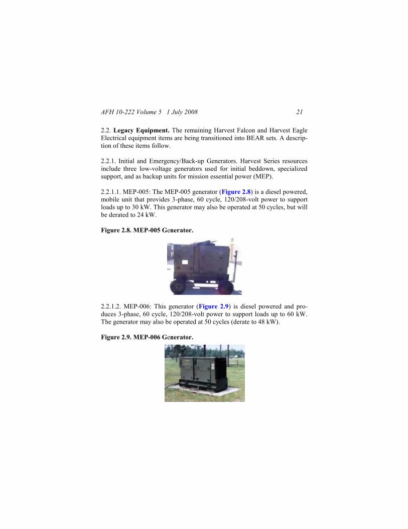
2.2. Legacy Equipment. The remaining Harvest Falcon and Harvest Eagle
Electrical equipment items are being transitioned into BEAR sets. A descrip-
tion of these items follow.
2.2.1. Initial and Emergency/Back-up Generators. Harvest Series resources
include three low-voltage generators used for initial beddown, specialized
support, and as backup units for mission essential power (MEP).
2.2.1.1. MEP-005: The MEP-005 generator (Figure 2.8) is a diesel powered,
mobile unit that provides 3-phase, 60 cycle, 120/208-volt power to support
loads up to 30 kW. This generator may also be operated at 50 cycles, but will
be derated to 24 kW.
Figure 2.8. MEP-005 Generator.
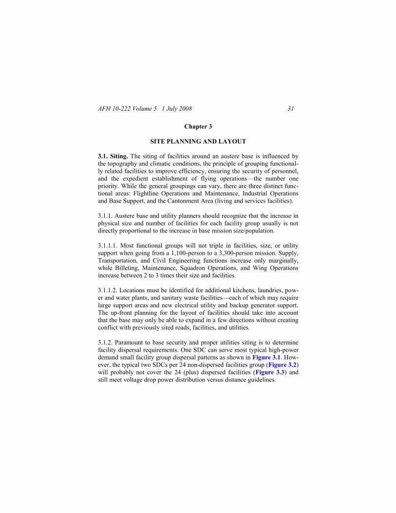
2.2.1.2. MEP-006: This generator (Figure 2.9) is diesel powered and pro-
duces 3-phase, 60 cycle, 120/208-volt power to support loads up to 60 kW.
The generator may also be operated at 50 cycles (derate to 48 kW).
Figure 2.9. MEP-006 Generator.

AFH 10-222 Volume 5 1 July 2008 22
2.2.1.3. MEP-007: This generator (Figure 2.10) is diesel-powered and pro-
duces 3-phase, 60 cycle, 120/208-volt or 240/416-volt power to support
loads up to 100 kW. It has a manual speed control. The generator may also
be operated at 50 cycles (derate to 80 kW).
Figure 2.10. MEP-007 Generator.
2.2.2. Primary Distribution Center (PDC). The PDC is a high-voltage switch-
ing station that receives and distributes 4,160-volt, 3-phase 3-wire delta elec-
trical power from up to four input sources, such as generators, commercial
power, or power distributed from another PDC (Figure 2.11). The PDC has
six outputs, three on each side of the PDC, which distribute 2,400/4,160-volt
(high-voltage), 60 Hz, 200-amp power to other components of the contin-
gency electrical distribution system. The cables are connected with load
break elbows (Figure 2.12) at the input side of the PDC from either the
MEP-12A generator, the output side feeders of another PDC, or from a
commercial power source. Except for the United States and Canada, there
are only a few regions in the world with 60Hz power. The PDC may be fed
from commercial power sources with 50Hz power from overseas commer-
cial sources. There are no measuring devices on the PDC to assist the opera-
tor in determining overload, phase balance, power factor or under-load
conditions for the individual feeders. The PDC weighs 6,660 pounds.

AFH 10-222 Volume 5 1 July 2008 23
Figure 2.11. Primary Distribution Center.
Figure 2.12. Load Break Elbow (secured with Grip-All clamp stick).
2.2.3. High-Voltage Distribution Cable. High-voltage, primary power is dis-
tributed on #1/0 aluminum, 5,000-volt, cross-linked polyethylene cable with
wrapped concentric ground wires. For primary distribution, three phases are
required – phases A, B, and C. If color codes are used, Phase A is Black,
Phase B is Red, and Phase C is Blue. Cable is supplied on 3,750-foot cable
reels, three reels per cable skid, one reel per phase as show in Figure 2.7.
Three cables reels on a skid weigh approximately 5,625 pounds, which
equates to about one-half pound per linear foot.
Note: While cables are labeled A, B, and C, they may not be shipped that
way. Also, be aware that if you are supporting a joint forces bed down, a
different color-coding scheme may be used. Always ensure that phases A, B,
and C are maintained throughout the entire system, and if used, color-coding
identification kept uniform for the entire electrical system.

AFH 10-222 Volume 5 1 July 2008 24
2.2.4. Secondary Distribution Center (SDC). The 150 kVA SDC receives
2,400/4,160-volt (at 60Hz), 3-phase 3-wire delta electrical power, and trans-
forms and distributes 120/208-volt (at 60Hz), 60-amp, 3-phase low-voltage
power (Figure 2.13). The 150 kVA SDC has one input source using three
load break elbows and provides secondary output through a dry type trans-
former to 16, 60-amp, cannon-type plugs.
Figure 2.13. Secondary Distribution Center.
2.2.4.1. The SDC has the capability to receive power from an emergen-
cy/back-up generator (MEP-005, 006, or 007) through a low-voltage cannon-
type plug. The SDC also has sub-station capability to distribute 2,400/4,160-
volt power to two other SDCs using two sets of three 3-phase cables with
load break elbows. When only one MEP-12A is required to provide power to
a limited area, the SDC may be used without a PDC to distribute primary
power through cables and load break elbows to other SDCs and users‘ power
distribution panels.
Note: This configuration provides a lower margin of safety for preventing
damage to the generator. In its standard configuration, the SDC is not
equipped with fuses to provide overcurrent protection during distribution of
primary power.
2.2.5. Secondary (Low) Voltage Distribution Cable. Low-voltage (120/208-
volt) power is distributed with two different sets of cable. Power from emer-
gency generators to the SDC is supplied with a 25 foot cable, which is either

AFH 10-222 Volume 5 1 July 2008 25
#4/0 200-amp cable, 3-phase 4 wire with ground, or #6 60-amp cable, 3-
phase 4 wire with ground (Figure 2.14). Low-voltage power is also distri-
buted from the SDC to power distribution panels with 50-foot and 100-foot
#6 60-amp cable, 3-phase 4 wire with ground. The cables use military-style
class-L connectors, also referred to as cannon plugs (Figure 2.15).
Figure 2.14. Mission Essential Generator Connected to SDC.
Figure 2.15. Low-Voltage Cables with Cannon Plug Connections.
2.2.6. Power Distribution Panel (PDP). The PDP is a low-voltage circuit
breaker panel. PDPs come in several sizes and functions: 15 kW, 25 kW, 30
kW, 60 kW, 100 kW, and 200 kW (Figure 2.16). The PDP receives

AFH 10-222 Volume 5 1 July 2008 26
120/208-volt, 3-phase power from the SDC and distributes and controls it in
a panel board under a weather resistant cover, or dead front panel. Individual
3-phase and single-phase circuit breakers control power output to military-
style Class L connectors and NEMA-style ‗twist lock‘ connectors, for con-
nection by cable to users‘ equipment.
Figure 2.16. Typical Power Distribution Panels.
2.2.6.1. The larger PDPs (i.e., 60 kW, 100 kW, and 200 kW) can provide
service as sub-distribution centers to other PDPs and major loads. Smaller
PDPs usually serve a single facility‘s HVAC, lighting, and utility outlet sys-
tems, and come with the facility being served.
2.2.6.2. In lieu of a PDP, some facilities such as aircraft hangars, large and
medium frame-supported tensioned fabric structures, Dome shelters, hard-
wall General Purpose (GP) shelters, and Expandable Shelter Containers
(ESCs) have power distribution centers that are a part of the facility.

AFH 10-222 Volume 5 1 July 2008 27
2.2.6.3. The 15, 25, and 30 kW PDPs have smaller cannon plug connections.
The 60, 100, and 200 kW PDPs should have 200 amp connection plugs, but
check on the type of connection required for the specific PDP and use the
T.O. Some PDP models may have to be hard-wired through the bottom of
the PDP panel if they do not have the larger 200 amp cannon plug connec-
tion.
2.2.7. Additional Associated Legacy Equipment. The following components
are also associated with the generation, installation, or operation of the lega-
cy electrical distribution systems.
2.2.7.1. Equipment Rack. The MEP-12A generator control panel can be re-
moved from the generator and moved to a remote location using a maximum
of 150-foot of control cable. An equipment rack (Figure 2.17) can hold up to
four control panels to supply a centralized control room for power plant op-
erations. The control room is generally located in an expandable shelter con-
tainer (ESC), or it can be situated in a tent or general purpose/medium
shelter. NOTE: The equipment racks will also be used with the DPGDS
systems.
Figure 2.17. Equipment Rack with Generator Control Panels.
2.2.7.2. Fuel Bladder System. Two 10,000-gallon fuel bladders are provided
for the power plant. An additional 10,000-gallon fuel bladder is included in

AFH 10-222 Volume 5 1 July 2008 28
the industrial operations set. The fuel bladder is either 22 feet wide by 22
feet long (Figure 2.18) or 12 feet wide by 42 feet long when unfolded from
the shipping container. When filled, the bladder is approximately 4 feet high
and its footprint shrinks about 1 to 2 feet in both directions. The bladder has
a filler/discharge connection on each end, one for fuel filling and one for
supplying the generators. The bladders also have a pressure relief valve/vent
assembly. The fuel is piped to the generators through a 3-inch diameter suc-
tion hose that is attached to a distribution hose. The distribution hose feeds a
fuel manifold (Figure 2.19), which then distributes the fuel to two, 1-inch
diameter, 25-foot long fuel lines that can supply two generators. The mani-
fold has a pass through capability to allow fuel to be further distributed to
additional manifolds.
Figure 2.18. Typical (22x22) Fuel Bladder.
Figure 2.19. Fuel Manifold.

AFH 10-222 Volume 5 1 July 2008 29
2.2.7.3. Remote Area Lighting System (RALS). The RALS is used to pro-
vide general, wide area lighting within the power plant area. The RALS has
250 feet of service cable and may be supported by either a SDC or MEP ge-
nerator. A RALS contains 13 telescopic two-lamp light poles, four 375-foot
cable sets, and an aluminum container/control box. Light poles are spaced
every 125 feet along the cable sets.
2.3. System Composition. A typical contingency electrical distribution sys-
tem is depicted in Figure 2.20.
2.3.1. When all system components are placed together, they create an elec-
trical system with three subsystems: power generation, primary power (high-
voltage) distribution, and secondary power (low-voltage) distribution.
2.3.2. The primary system components are tied together with high-voltage
cable, using load break elbows, from the prime generator through the
PSC/PDC, and on to the SDC.
2.3.3. The secondary system starts at the SDC and is provided to the user's
PDP, or service panel, through secondary voltage cables using cannon plug
connectors. The input can be made from either a prime generator, the output
side feeders of another PSC/PDC, or from a commercial power source.

AFH 10-222 Volume 5 1 July 2008 30
Figure 2.20. Basic Electrical Distribution System Schematic.
AFH 10-222 Volume 5 1 July 2008 31
Chapter 3
SITE PLANNING AND LAYOUT
3.1. Siting. The siting of facilities around an austere base is influenced by
the topography and climatic conditions, the principle of grouping functional-
ly related facilities to improve efficiency, ensuring the security of personnel,
and the expedient establishment of flying operations—the number one
priority. While the general groupings can vary, there are three distinct func-
tional areas: Flightline Operations and Maintenance, Industrial Operations
and Base Support, and the Cantonment Area (living and services facilities).
3.1.1. Austere base and utility planners should recognize that the increase in
physical size and number of facilities for each facility group usually is not
directly proportional to the increase in base mission size/population.
3.1.1.1. Most functional groups will not triple in facilities, size, or utility
support when going from a 1,100-person to a 3,300-person mission. Supply,
Transportation, and Civil Engineering functions increase only marginally,
while Billeting, Maintenance, Squadron Operations, and Wing Operations
increase between 2 to 3 times their size and facilities.
3.1.1.2. Locations must be identified for additional kitchens, laundries, pow-
er and water plants, and sanitary waste facilities—each of which may require
large support areas and new electrical utility and backup generator support.
The up-front planning for the layout of facilities should take into account
that the base may only be able to expand in a few directions without creating
conflict with previously sited roads, facilities, and utilities.
3.1.2. Paramount to base security and proper utilities siting is to determine
facility dispersal requirements. One SDC can serve most typical high-power
demand small facility group dispersal patterns as shown in Figure 3.1. How-
ever, the typical two SDCs per 24 non-dispersed facilities group (Figure 3.2)
will probably not cover the 24 (plus) dispersed facilities (Figure 3.3) and
still meet voltage drop power distribution versus distance guidelines.

AFH 10-222 Volume 5 1 July 2008 32
Figure 3.1. Dispersal Patterns for 3-, 6-, 9-, and 12-Facility Groupings.
Figure 3.2. SDC Placement for Non-Dispersed 24-Facility Grouping.

AFH 10-222 Volume 5 1 July 2008 33
Figure 3.3. Insufficient No. of SDCs for Dispersed 24-Facility Grouping.
3.1.2.1. If most or all facilities require ECUs (such as for billeting) and/or
high-quality power with little voltage drop, a significant increase in SDC
numbers will be required to support the same number of facilities (Figure
3.4). Facilities that do not require higher quality power can be located further
distances from SDCs, thus requiring fewer numbers to support the same
number of facilities as shown in Figure 3.3. While it is possible to change
SDC transformer taps to account for voltage drop on longer runs, it is time
consuming and will slow down rapid replacement of a failed SDC, and could
provide voltage that is too high for some facilities.
Figure 3.4. Five SDCs Supporting Dispersed 24-Facility Grouping.

AFH 10-222 Volume 5 1 July 2008 34
3.1.3. Austere base officials and site planners must examine the threat and
determine with the air base defense (ABD) forces if dispersal is the best
means for protection. Even in higher threat areas, the topography, enemy
capabilities, and the base defense force measures (such as use of force pro-
tection and CCD techniques) may allow semi- or non-dispersed facility pat-
terns within groups to be used much more effectively with wider group
separation distances. Eliminating unnecessary terrain with priority targets is
a consideration, as it may require more ABD forces to defend. Having fewer
widely dispersed facilities within a group also gives added flexibility to
ABD forces, providing greater control for lines of sight and avenues of ap-
proach to non-dispersed and/or critical resources.
3.2. Site Planning. By the time most power production and electrical per-
sonnel begin arriving on site to set up the power plant and electrical distribu-
tion system, the basic site planning and paper layout for the base may well
have been accomplished. Sectors and basic planning modules of facility
groupings will have been designated for air base operations, support, and
defense. If an austere base is being established with a view toward expan-
sion, then growth needs to be addressed during all stages. Therefore, the
layout of individual facilities during the initial stages of layout should also
take growth of the utility systems into account.
3.2.1. When installing contingency electrical distribution systems, consider
the timelines for installation and growth, assets available to you at each stage
of growth, whether additional assets are needed and available, and the dura-
tion of the deployment. These considerations will affect installation planning
decisions and the operating and expansion capabilities. Decide up front
where to specifically locate major electrical components within the time
frames and resources given. Establishment of an austere base normally fol-
lows a pattern that is comprised of four stages: 1-initial, 2- intermediate, 3-
follow-on, and 4-sustainment. The critical tasks for establishing a power
generation and distribution system are found in the first two stages.
3.2.1.1. Initial Stage. During the initial stage of an austere base development,
engineer efforts are concentrated on accomplishing those tasks that are ne-

AFH 10-222 Volume 5 1 July 2008 35
cessary to meet the requirement for combat sortie generation within 72
hours. The following tasks are included in the initial stage.
3.2.1.1.1. Provide mission essential power to critical facilities using mobile
generators (up to 100 kW in size).
3.2.1.1.2. Set up emergency security/area lighting.
3.2.1.1.3. Start layout and trenching for utility systems.
3.2.1.2. Intermediate Stage. During the intermediate stage of austere base
development, emphasis is to provide the ability for all base agencies and
functions to establish basic operating capability within the first 10 days of
deployment. The primary electrical power concern is to establish a base
power system and connect facilities to it as the facilities are erected. Tasks in
this stage include:
3.2.1.2.1. Establishing power plant(s).
3.2.1.2.2. Laying out and burying the high-voltage distribution cabling and
connecting the primary and secondary distribution centers.
3.2.1.2.3. Connecting base facilities to power system as they are erected.
3.2.1.2.4. Connecting back up generators to mission critical facilities after
they are connected to the power grid.
3.2.2. Upon arrival at the deployed location, start gathering facts that will
dictate the type of power system required. Some facts you will need are:
3.2.2.1. If the threat is low and the size of the base is only a 1,100-person
package, only one centralized power plant may be all that is needed.
3.2.2.2. If facility dispersal is required, two power plants will probably be
required to cover the extended area.

AFH 10-222 Volume 5 1 July 2008 36
3.2.2.3. If two plants are required, are enough PSCs/PDCs available?
3.2.2.4. Can plants be set up to allow a connection between power plants?
3.2.2.5. Is there enough cable to connect between the power plants?
3.2.2.6. Can SDCs from the separate plants be located close enough to quick-
ly lay and park cable between critical SDCs for redundancy?
3.2.3. For an 1,100-person package, the issues above may be easily ad-
dressed after rechecking facility groupings, loads, and layout plans. Howev-
er, the situation can become increasingly complicated when considering
additional transient aircraft, personnel support, and/or beddown expansions
above 3,300 persons, especially if dispersed. The larger the size of the area
to be served, the more resources required for setup, support, and security.
3.2.4. Determine the system power factors and how they may affect your
power plant operations throughout the planning, installation, and operation
of the electrical generation and distribution system,. Consider the following
basic limiting factors when laying out the electrical system during the initial
and intermediate stages of installation. These system limitations are based on
transmission and distribution distances from the generators to the PSC/PDC,
the PSC/PDC to the SDCs, and the SDCs to the PDPs.
3.2.4.1. Keep the primary (high-voltage) power cable runs between the
MEP-12s and PDCs to the shortest distance possible.
3.2.4.2. Limit the primary (high-voltage) power cable runs from the
PSC/PDC to the SDCs to 1.0 mile where the SDCs are grouped at the end of
the run. A 1-mile run may still experience excessive voltage drop, but can be
partially compensated for by adjusting the tap settings of the SDC. To avoid
changing tap settings, limit the length of a run from the PSC/PDC to the
SDCs to 4,000 feet.

AFH 10-222 Volume 5 1 July 2008 37
3.2.4.3. Primary runs between the PSC/PDC and SDCs should not exceed
2.0 miles where the SDCs are equally distributed along the run. Again, a 2-
mile run may experience excessive voltage drop that requires SDC tap ad-
justments. To avoid changing tap settings, limit the length of a run from the
PSC/PDC to the SDCs to 1.5 miles.
3.2.4.4. Limit secondary runs from SDCs to PDPs and facility distribution
panels to 750 feet when it is necessary to keep the voltage drop below 10%
for the serviced facility. Longer runs may be made for emergency use and
use with resistance type equipment less vulnerable to voltage drops.
3.2.5. Electrical distribution schematic. When the overall base-planning
layout is being developed, an electrical distribution schematic should be a
major component for base support. During the beddown process, planners,
power production, and electrical personnel need to calculate, determine,
and/or identify load factors, demand, maximum draw, and diversified load as
related to individual facility groups. The specific information is used to de-
velop a detailed secondary distribution schedule, placement of mission es-
sential generators, and develop individual feeder schedules used for
installation. Given time and expertise, going into this amount of detail during
the initial beddown planning will significantly limit the need to relocate
SDCs, re-site/relocate facilities, and relocate cable runs. During initial plan-
ning, basic planning factors can be followed to help minimize reaccomplish-
ing work. Detailed schedules should be accomplished prior to installing the
electrical distribution system.
3.2.6. Basic electrical planning factors. During normal operations, not every
prime generator will be running at full load all the time. The system design
should take into consideration the number of generators that will operate
fully loaded around the clock at each power plant.
3.2.6.1. For a 1,100-person base, there may be three or four generators at the
main plant and one or two generators at the flightline plant. Only one of the
two generators may be required for 24-hour operations at the flightline plant.

AFH 10-222 Volume 5 1 July 2008 38
Only one generator at the main plant may be required to operate at full load
over night.
3.2.6.2. Where environmental control units sustain their continuous maxi-
mum amperage draw, consider the maximum load that one generator can
support through the PSC/PDC and SDCs. The total load on each SDC should
not exceed 150 kVA and the load on each SDC circuit should not exceed
21.6 kVA.
3.2.6.2.1. One MEP-12, 750 kW generator (operating at 80% of its maxi-
mum capacity) will support no more than 5 SDCs per one 200-amp
PSC/PDC output circuit when facilities are operating at maximum loads with
FD-ECUs.
3.2.6.2.2. Under normal operating loads, a power plant with at least two ge-
nerators operating will support 6 to 10 SDCs per PSC/PDC circuit when
facilities have FDECUs, and 10 to 15 SDCs per circuit when facilities do not
have FDECUs.
3.2.6.2.3. In the DPGDS system, each SDC has two high voltage output cir-
cuits. There are two sets of loadbreak elbow connections for feed through
capabilities to additional SDCs. A maximum of five SDCs can be supported
from point of origin (power source). Only 10 shelters per SDC can be con-
nected when the FDECU is used in each shelter. By properly balancing the
number of SDCs per plant, the number of SDCs per PSC/PDC should not
exceed this maximum number.
Warning
At full load, the FDECU draws 41 amps. For
ambient temperatures over 125 F, do not op-
erate SDCs over 80% load (i.e., no more than
8 of 16 output connections used).

AFH 10-222 Volume 5 1 July 2008 39
3.3. Layout. Layout decisions must consider the threat, type of system to be
installed (radial or loop), and expected final size of the base being supported.
3.3.1. Most expeditionary bases with a recognized threat have to first consid-
er the basic expeditionary base structure from an air base defense point-of-
view, combined with normal base operating requirements. In many cases, the
tactical area of responsibility (AOR) boundary for base defense may dictate
the initial installation pattern for the electrical system. For some locations,
the tactical AOR may dictate a linear base structure (Figure 3.5), that is de-
signed along a flightline where the base is long and narrow. In this case, a
radial electrical distribution system (Figure 3.6) may initially be required.
3.3.2. When defense boundaries allow a more conventional layout to be con-
sidered, especially if the base will be larger than one or two squadrons, sup-
port facilities, billeting, and services functions can be progressively moved
away from the flightline and industrial support functions (Figure 3.7).
Figure 3.5. Linear Base Layout.

AFH 10-222 Volume 5 1 July 2008 40
Figure 3.6. 1,100-Person Radial Electrical Distribution System.
Figure 3.7. Conventional Type Base Layout.

AFH 10-222 Volume 5 1 July 2008 41
3.3.2.1. For this type layout, a simple interconnected electrical distribution
system, referred to as a loop electrical distribution system, may be possible
between two power plants, even during the initial installation. If a base has
two or more PDCs, or two or more sets of PSCs, it may be possible to run a
completely looped system. Two sets of cables would interconnect the PSCs/
PDCs in a ring (Figure 3.8).
Figure 3.8. 1,100-Person Looped Electrical Distribution System.
3.3.2.2. If this is not possible, at least one set of additional cables should be
run to allow interconnecting between PSCs/PDCs (Figure 3.9). This will
allow interconnecting the systems if generators have to be taken off-line or
additional loads are added.
3.3.2.3. For critical facilities, especially those that require backup generators,
SDCs can also be connected with parked cables (Figure 3.10). This will al-
low SDCs to be quickly connected in case one of the feeder circuits is dis-
rupted.

AFH 10-222 Volume 5 1 July 2008 42
Figure 3.9. 1,100-Person Interconnected Electrical Distribution System.
Figure 3.10. Critical Facility SDCs Connected By Parked Cables.
3.3.3. Power Plant Layout. There is no mandatory way to lay out individual
equipment items as long as available resources are not exceeded, systems
can operate safely, and the system is installed in a secure environment. Key
concerns for laying out the plants are: security of critical resources, available
land for the power plant, siting to prevent noise intrusion, siting for system
redundancy, vehicle and equipment accessibility, and the available lengths of
cable and fuel lines, especially during initial arrival. See Chapter 5 for spe-
cifics on contingency power plant layouts.

AFH 10-222 Volume 5 1 July 2008 43
3.3.4. Typical Facility Groups. Deployment packages are standardized for
the types of facility structures that serve each functional grouping. For plan-
ning purposes, functional groupings vary little and carry a common designa-
tion. The following tables identify basic designations for facility groups and
types of structures supplied to house major functions (Tables 3.1 and 3.2).
Changes in number of assets within UTCs may cause variations; always con-
firm what the final configuration of assets will be for your deployment.
Table 3.1. 1,100-Person Bare Base Facility List.
Area Facility Group
Structure Type
TEMP/
SSS
ESC GPS/
MSS
ACH FSTFS/
Dome
A Avionics 1 3
B1,
B2,
Lodging (may be
subdivided by female,
enlisted,& officer)
and Services Admin
105
C Chapel 1
D Services (Dining Hall) 1 (9-1)
E Engineer 14 1 3
F Maintenance 4 10 5 2 1
G Squadron Operations 1 1 1
H Support Group 8 5 2
I Emergency Services 10
J Aerial Port 3
L Laundry 2
M Munitions 1 3
P POL 1 1
R Alert 3
S Supply 2 2 7
T Transportation 2 3
W Wing Operations 10 3
X Hospital
Y Communications
Z Airfield Facilities
EW1, EW2 Water Plant(s) 2

AFH 10-222 Volume 5 1 July 2008 44
Table 3.2. 3,300-Person Bare Base Facility List.
Area Facility Group
Structure Type
TEMP/
SSS
ESC GPS/
MSS
ACH FSTFS/
Dome
A Avionics 1 3 4
B1, B2 Lodging (may be sub-
divided by female,
enlisted,& officer) and
Services Admin
315
C Chapel 1
D1, D2 Services (Dining Hall) 2 (9-1)
E Engineer 19 3 3
F Maintenance 6 12 12 4 1
G1, G2 Squadron Operations 4 3 2
H Support Group 18 5 2
I Emergency Services 13
J Aerial Port 5 2
L Laundry 6
M Munitions 2 6
P POL 1 1
R Alert 3
S Supply 3 2 7
T Transportation 3 3
W Wing Operations 25 3
X Hospital
Y Communications
Z Airfield Facilities
EW1, EW2 Water Plant(s) 6
3.3.4.1. Which facilities go where varies from location to location. In most
cases, physical size and topographic conditions may constrain or dictate the
basic base layout (e.g., a linear or conventional layout). The functional inter-
relation of flightline operations, maintenance, and command structures may
also dictate that some facilities and functions be collocated differently, espe-
cially if the base supports other US or allied military services.
AFH 10-222 Volume 5 1 July 2008 45
3.3.4.2. All deployment eligible CE units should practice the layout of func-
tional areas during home station training. Layouts should focus on which
facilities require close proximity to each other, both within and between fa-
cility groups, in order to function effectively and efficiently. Site planners
need this information during the ―Open the Airbase‖ phase of the deploy-
ment. This will also provide the opportunity for power production and elec-
trical systems personnel to practice layout of the electrical generation and
distribution system and calculate secondary distribution requirements and
feeder schedules.
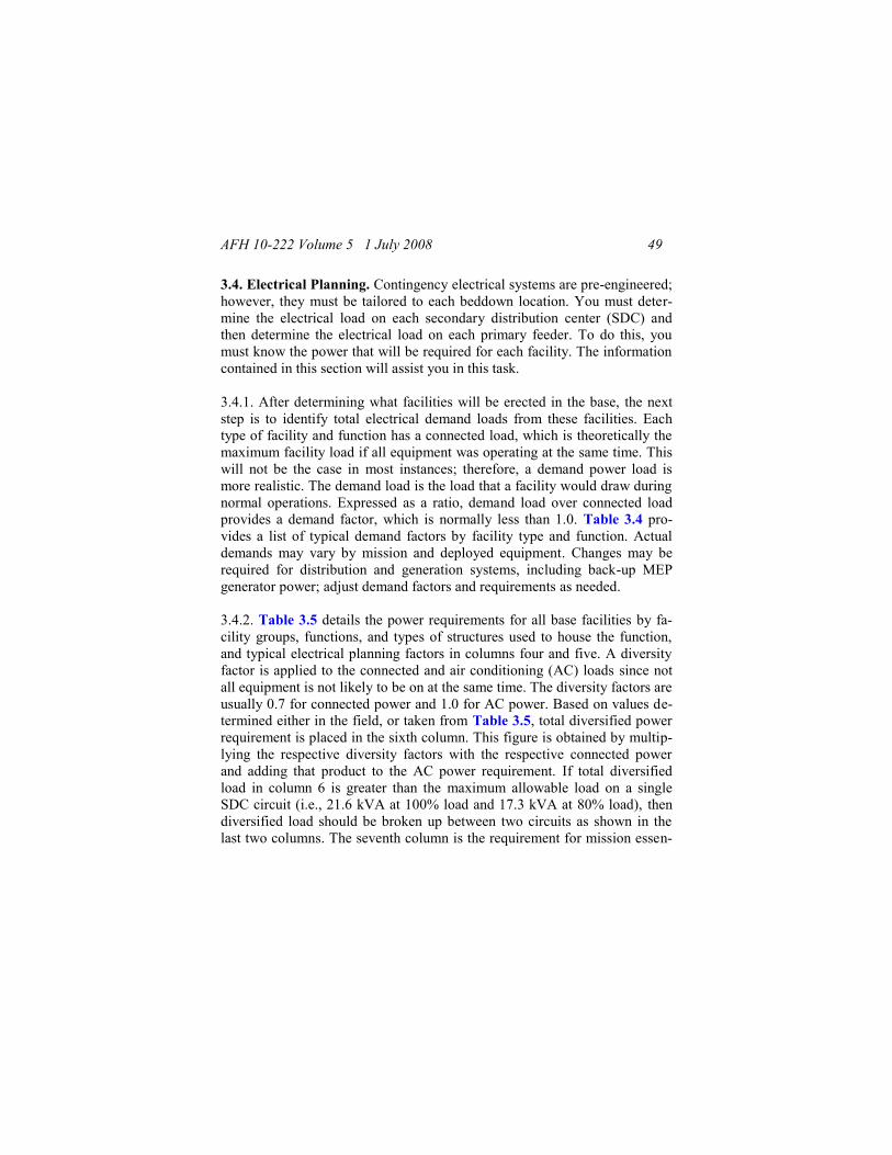
3.3.4.3. Cables provided with electrical generation and distribution systems
are adequate for initial installation based on non-dispersed facility separation
guidelines found in Table 3.3. However, if high-threat conditions require
facility dispersal at the maximum distances indicated in Table 3.3, some
non-critical facilities may require portable generator support, and/or addi-
tional primary and secondary cable and connectors. Be aware that required
separation criteria for some facilities (such as Munitions, POL, and LOX)
can be varied based on terrain, protection of assets, and mission/weapons
systems and should be determined for each individual base. This could have
a major impact on the layout of power plants, SDCs, and MEP generators.
Table 3.3. General Separation Distances for Facilities in Groups.
Facility Groups
Facilities to be Separated
Distances (feet)
Non-
Dispersed Dispersed
Billeting Between tents
(in separate billeting groups)
30 150
Between tents
(side by side, same group)
12 12 to 20
Between tent rows (same group) 30 30 to 60
Between tents and la-
trines/shower shave units
60 +
(100 1)
60+
(100 1)
Billeting & Industrial/Flightline
groups, except Trans & Flying
Squadrons
150 2
150 2
1,600
900

AFH 10-222 Volume 5 1 July 2008 46
Facility Groups
Facilities to be Separated
Distances (feet)
Non-
Dispersed Dispersed
Shelters (ACH,
GP, FSTFS)
Between shelters
(side by side, same group)
30 60+
Between shelter rows 60 60+
Between shelters
(side by side, different groups)
150+ 200+
Industrial and
Flightline Shops
Between shops
(side by side, same group)
30 60
Between shop rows (same
groups)
30 30 to 60
All Groups
(except Lodging,
Munitions, LOX,
& POL)
Between groups 150 200
Munitions Within Munitions area See note 3 See note 3 Munitions to inhabited facilities See note 3 See note 3
Munitions area, LOX, and POL See note 3 See note 3 LOX facility LOX and inhabited facilities 1,500+ 1,500+
LOX and POL 2,640+ 2,640+
POL complex POL and inhabited facilities 2,640+ 2,640+
Notes: 1 Suggested per sanitation criteria, AFPAM 91-216, USAF Safey
Deployment and Contingency Pamphlet 2 Noise and industrial type lighting are factors in siting criteria
3 Per AFMAN 91-201, Explosive Safety Standards, Chap 3, see
Austere Area Criteria
3.3.5. Growing from a 1,100- to a 3,300-Person Base. As previously men-
tioned, when a 1,100-person base expands by 2,200 persons to accommodate
two additional squadrons, or even other missions, most assets needed for
expansion usually do not triple with the population. When laying out the
base, be aware that some functions require additional planning, either due to
large size (i.e., an aircraft hangar, FSFTS shelter, a 9-1 kitchen, or a medical
facility) or minimum separation requirements (i.e., a power or sewage plant).

AFH 10-222 Volume 5 1 July 2008 47
3.3.5.1. An effective way to manage and delineate where facility groups will
be placed is to locate and line up the facility groups within a network of
travel and emergency response routes consisting of flightline pavement,
roadways, and utility corridors (Figure 3.11).
Figure 3.11. Typical 1,100-Person Layout with Major Roadway Grid.
A Avionics F Maintenance R Alert
B1,2 Billeting G1,2 Squadron Ops S Supply
C Chaplain H Support Group T Transportation
D1,2 Dining Hall I Emergency Svcs W Wing HQ
E Engineering J Aerial Port X Medical Fac.
EP1,2 Power Plant(s) L Laundry Y Comm Plant(s)
ES1,2 Sewage Treatment M Munitions
EW1,2 Water Plant(s) P POL
3.3.5.1.1. If the base does not have a basic roadway system already estab-
lished, then fire, security, and base planners need to make this a priority in
the layout process. Roadways should be created and fit easily between the
groups (within the group separation distances), while utility corridors and
utility right-of-ways would run along and between the groups and roadways.

AFH 10-222 Volume 5 1 July 2008 48
3.3.5.1.2. Facility group grids should then be established within the ―blocks‖
created by roadways. Plan ahead; orient the tents/shelters and maintain ade-
quate distances between each tent/shelter to allow room for ECUs and other
utilities. Otherwise, utility corridors can become cluttered with equipment,
which will make repairs, maintenance, emergency response, and removal of
equipment more difficult.
3.3.5.2. With expansion, facilities will grow within the roadway system
blocks (Figure 3.12). Flightline facilities (such as Maintenance and Squa-
dron Operations) normally grow along the flightline. Industrial operations
and base support functions (such as Civil Engineering, Wing Operations, and
Support Group) normally expand outward and away from each other. Billet-
ing functions normally expand away from the industrial operations, while
additional key personnel services support functions (i.e., MKTs, latrines, 9-1
kitchens, and laundry) are located in areas where personnel are massed.
Areas need to be reserved to allow for the growth of existing power and se-
wage plants and placement of new power plants.
Figure 3.12. Typical Growth from 1,100- to 3,300-Person Layout.
AFH 10-222 Volume 5 1 July 2008 49
3.4. Electrical Planning. Contingency electrical systems are pre-engineered;
however, they must be tailored to each beddown location. You must deter-
mine the electrical load on each secondary distribution center (SDC) and
then determine the electrical load on each primary feeder. To do this, you
must know the power that will be required for each facility. The information
contained in this section will assist you in this task.
3.4.1. After determining what facilities will be erected in the base, the next
step is to identify total electrical demand loads from these facilities. Each
type of facility and function has a connected load, which is theoretically the
maximum facility load if all equipment was operating at the same time. This
will not be the case in most instances; therefore, a demand power load is
more realistic. The demand load is the load that a facility would draw during
normal operations. Expressed as a ratio, demand load over connected load
provides a demand factor, which is normally less than 1.0. Table 3.4 pro-
vides a list of typical demand factors by facility type and function. Actual
demands may vary by mission and deployed equipment. Changes may be
required for distribution and generation systems, including back-up MEP
generator power; adjust demand factors and requirements as needed.
3.4.2. Table 3.5 details the power requirements for all base facilities by fa-
cility groups, functions, and types of structures used to house the function,
and typical electrical planning factors in columns four and five. A diversity
factor is applied to the connected and air conditioning (AC) loads since not
all equipment is not likely to be on at the same time. The diversity factors are
usually 0.7 for connected power and 1.0 for AC power. Based on values de-
termined either in the field, or taken from Table 3.5, total diversified power
requirement is placed in the sixth column. This figure is obtained by multip-
lying the respective diversity factors with the respective connected power
and adding that product to the AC power requirement. If total diversified
load in column 6 is greater than the maximum allowable load on a single
SDC circuit (i.e., 21.6 kVA at 100% load and 17.3 kVA at 80% load), then
diversified load should be broken up between two circuits as shown in the
last two columns. The seventh column is the requirement for mission essen-

AFH 10-222 Volume 5 1 July 2008 50
tial power; standard values are provided in the table, but use the specific,
mission-essential equipment loads if known.
Table 3.4. Typical BEAR Demand Factors.
Type
Facility
Function Demand
Factor
Type
Facility
Function Demand
Factor
Temper
Tent / Small
Shelter
System
Wing Admin/
Command
0.9 ACH Hangar 0.9
Billets 1.0 ESC Engr Power Plant 1.0
9-1 Kitchen 0.9 Avionics Shop 0.7
Shower-Shave 0.9 Pneudraulics Shop 0.7
Latrine 0.8 NDI Shop 0.7
Laundry 0.9 Elect Shop 0.7
Engr Utility Shop 0.6 Bearing Shop 0.7
Engr Structures 0.6 Parachute Shop 0.8
Engr Electrical 0.6 Wheel/Tire Shop 0.7
Engr Fuels 0.6 Gen. Maint Shop 0.7
Squadron Ops 0.9 Life Support Shop 0.8
Base Admin 0.9 BX 0.8
Post Office 0.9 Communications 0.7
Legal Office 0.9 Armory 0.9
BX 0.9 SRC 0.9
Chapel 0.9 POL Lab 0.7
MWRS 0.8 Sup Processing 0.8
Fire Operations 0.7 GP Shel-ter /
Medium
Shelter System
Wing Intelligence 0.8
Fire Tech Srvs 0.8 Warehouse 0.6
EOD 0.7 Avionics Shop 0.7
Base Operations 0.7 Engr Pow Pro 0.6
Engr Readiness 0.7 Engr Eqpt Shop 0.6
Mortuary 0.8 Propulsion Shop 0.7
Aerial Port 0.8 AGE Shop 0.7
Alert Facility 0.9 Gen. Maint Shop 0.8
Vehicle Ops 0.7 Sqd Ops Support 0.7
TMO 0.7 Gen. Support 0.7
Wing Briefing 0.9 Aerial Port 0.8
Wing Ops/ Plans 0.8 FSTFS
Munitions Maint 0.7
Wing Intelligence 0.8 Propulsion Shop 0.8
Maint/Job Cntr 0.8 Supply Storage 0.9
Maint Mat Cntr 0.7 Vehicle Maint 0.7
Maint QC 0.8 Packing/Crating 0.7

AFH 10-222 Volume 5 1 July 2008 51
Table 3.5. Typical Harvest Falcon Electrical Planning Factors.
Facility
Group
Function
Shelter
Type
Power Requirement
(Kilovolt-Ampere [kVA])
kVA per
Circuit
Max
Load
AC
Load Div.
MEP
Load #1 #2
A
Avionics
Avionics 15 kVA
General Avionics
Latrine
RALS
ESC
GP
TT
15.0
15.0
6.0
7.2
10
20
20.5
30.5
4.2
5.0
11 20.5
20.5
4.2
5.0
10
B
Billeting
Billets
Latrine
Shower/shave
RALS
TT
TT
TT
4.5
6.0
6.0
7.2
10 13.5
4.2
4.2
5.0
13.5
4.2
4.2
5.0
C
Chaplain
Chapel TT 7.8 10 5.5 15.5
D
Services
9-1 Kitch-
en/Dining
RALS
TT Up to
1501
7.2
70 150 ±
251
5.0
60 to
100 2
5.0
150 ±
252
E
Engineer
Eng Command
Eng Mngmt
Mat. Control
Eng Operations
Utilities
Structures
HVAC
Fuels
Electrical
Entomology
Power Pro
Equipment
Power Pro
Water Plant
Latrine
Eng Support
RALS
TT
TT
TT
TT
TT
TT
TT
TT
TT
TT
GP
GP
ESC
TT
TT
GP
5.2
4.9
7.0
4.6
5.8
11.6
7.8
7.2
7.3
5.8
9.7
6.9
5.8
5.0
6.0
6.9
7.0
10
10
10
10
10
10
10
10
10
10
20
20
10
10
20
13.6
13.4
14.9
13.2
14.1
18.1
15.5
15.0
15.1
14.1
26.8
14.8
14.1
13.5
4.2
24.8
5.0
3
13.6
13.4
14.9
13.2
14.1
18.1
15.5
15.0
15.1
14.1
16.8
14.8
14.1
13.5
4.2
14.8
5.0
10
10
10

AFH 10-222 Volume 5 1 July 2008 52
Facility
Group
Function
Shelter
Type
Power Requirement
(Kilovolt-Ampere [kVA])
kVA per
Circuit
Max
Load
AC
Load Div.
MEP
Load #1 #2
F
Mainte-
nance
Pneudraulics
NDI
Propulsion
Propulsion
Electrical
Bearing Clean
AGE
Command/Adm.
Parachute
Hangar
Wheel/Tire
Latrine
Gen Maint Sup.
Gen Maint Sup.
RALS
ESC
ESC
FSTFS
GP
ESC
ESC
GP
TT
ESC
ACH
ESC
TT
GP
ESC
28.1
7.7
36.0
15.0
15.6
5.8
8.2
6.2
6.6
36.0
6.0
6.0
10.0
8.0
7.2
10
10
20
10
10
20
10
10
10
20
10
29.7
15.4
25.2
30.5
20.9
14.1
25.7
14.3
14.6
25.2
14.2
4.2
27.0
15.6
5.0
20
21
10
11
6
4
5
25
19.7
15.4
15.2
20.5
20.9
14.1
15.7
14.3
14.6
15.2
14.2
4.2
17.0
15.6
5.0
10
10
10
10
10
10
G Squad
Ops
Squadron Ops.
Life Support
Latrine
Squad Ops. Sup.
RALS
TT
ESC
TT
GP
5.9
5.7
6.0
6.5
7.2
10
10
20
14.1
14.0
4.2
24.6
5.0
4
4
14.1
14.0
4.2
14.6
5.0
10
H
Support
Group
Reproduction
Post Office
BITS
Legal/Contract.
Personnel
Administration
Latrine
Exchange
Exchange
Gen Support
Communications
MWRS
Armory
Command/SRC
RALS
TT
TT
TT
TT
TT
TT
TT
TT
ESC
GP
ESC
TT
ESC
ESC
5.6
3.9
5.2
4.9
4.6
5.0
6.0
6.0
8.0
7.0
9.0
4.6
4.5
4.5
7.2
10
10
10
10
10
10
10
10
20
10
10
10
10
13.9
12.7
13.6
13.4
13.2
13.5
4.2
14.2
15.6
24.9
16.3
13.2
13.2
13.2
5.0
6
4
13.9
12.7
13.6
13.4
13.2
13.5
4.2
14.2
15.6
14.9
16.3
13.2
13.2
13.2
5.0
10
I
Emer-
gency
Services
Fire Tech Svs.
Fire Operations
Security Police
Disaster Prep.
EOD
Base Operations
RALS
TT
TT
TT
TT
TT
TT
5.0
4.5
4.5
4.5
6.2
4.5
7.2
10
10
10
10
10
10
13.5
13.2
13.2
13.2
14.3
13.2
5.0
4
3
3
4
13.5
13.2
13.2
13.2
14.3
13.2
5.0
J
Aerial
Port
Mortuary
Aerial Port
Port Support
RALS
TT
TT
GP
6.3
4.5
6.5
7.2
10
10
20
14.4
13.2
24.6
5.0
4
3
14.4
13.2
14.6
5.0
10

AFH 10-222 Volume 5 1 July 2008 53
Facility
Group
Function
Shelter
Type
Power Requirement
(Kilovolt-Ampere [kVA])
kVA per
Circuit
Max
Load
AC
Load Div.
MEP
Load #1 #2
L
Laundry
Laundry TT 10 10 17.0 17.0
M
Muni-
tions
Command/Adm.
Tool Crib
Munitions Maint.
RALS
TT
TT
GP
6.5
5.0
8.2
7.2
10
10
20
14.6
13.5
25.7
5.0
5
4
6
14.6
13.5
15.7
5.0
10
P
POL
Administration
Laboratory
RALS
TT
ESC
5.4
4.5
7.2
10
10
13,8
13.2
5.0
13.8
13.2
5.0
R
Alert
Alert Facility
RALS
TT 5.4
7.2
10 13.8
5.0
4 13.8
5.0
S
Supply
Command/Adm.
Demand Proc.
Latrine
Storage
RALS
TT
ESC
TT
FSTFS
5.1
5.1
6.0
10.0
7.2
10
10
13.6
13.6
4.2
7.0
5.0
13.6
13.6
4.2
7.0
5.0
T
Trans-
portation
Vehicle Ops.
TMO
Latrine
Vehicle Maint.
Packing/Crating
TT
TT
TT
FSTFS
FSTFS
4.5
4.5
6.0
18.5
12.0
10
10
13.2
13.2
4.2
13.0
8.4
13.2
13.2
4.2
13.0
8.4
W
Wing
Ops
Administration
Briefing
Plans
Operations
Targets
Intelligence
Intelligence
Maint Command
Job Control
Material Control
Quality Control
Maint Analysis
Maint Records
Maint Plans
Latrine
Finance
Command Post
Command/Adm.
RALS
TT
TT
TT
TT
TT
TT
ESC
TT
TT
TT
TT
TT
TT
TT
TT
TT
ESC
ESC
5.7
7.0
4.5
4.6
4.5
5.6
5.6
4.5
4.8
6.3
6.3
4.5
4.5
6.3
6.0
4.5
7.0
5.7
7.2
10
10
10
10
10
10
10
10
10
10
10
10
10
10
10
10
10
14.0
14.9
13.2
13.2
13.2
13.9
13.9
13.2
13.4
14.4
14.4
13.2
13.2
14.4
4.2
13.2
14.9
14.0
5.0
5
3
4
4
4
4
4
4
14.0
14.9
13.2
13.2
13.2
13.9
13.9
13.2
13.4
14.4
14.4
13.2
13.2
14.4
4.2
13.2
14.9
14.0
5.0
X
Medical
Facility
See Specific
Type of Facility
Requirements
* * * *

AFH 10-222 Volume 5 1 July 2008 54
Facility
Group
Function
Shelter
Type
Power Requirement
(Kilovolt-Ampere [kVA])
kVA per
Circuit
Max
Load
AC
Load Div.
MEP
Load #1 #2
Y
Commu-
nications
See Specific
Type of Facility
Requirements
* * * *
Z
Airfield
Facilities
See Specific
Type of Facility
Requirements
* * * *
EW
Water
Plants
Per Specific
Requirements
* * * *
Notes: 1 Loads vary for deployed freezer units. 2 Loads vary and may increase as new equipment comes into the invento-
ry. To prevent generator overload, two generators may be required even
when level of service is reduced and some equipment is isolated.
3.4.3. Bear in mind that the electrical loads shown for the various facilities
are estimated in many cases. Oftentimes users bring additional or differing
equipment that could alter these figures. If time permits, check to see what
equipment is actually being supported, particularly in those areas related to
flightline maintenance operations. Do not be surprised to see containerized
facilities arrive; some organizations such as the hospital have these types of
buildings for specialized functions. During your planning efforts it would be
wise to save a couple of circuits from the SDCs for these specialized facili-
ties, at least in the hospital and aircraft maintenance facility groups.
3.4.4. Pre-deployment discussions with aircraft maintenance, weapons, and
medical personnel prior to deployment may reveal unit-unique power re-
quirements greater than those normally supported by contingency electrical
distribution systems. The facility diversity factor for each plant should be
evaluated during operations by checking the average daily peak demand ver-
sus the total facility demand. A major difference from planned versus actual
loads may justify rerouting electrical service to achieve greater efficiencies.
3.4.5. After the diversified loads are identified and excessive loads split be-
tween circuits, the next step is to identify how many of each facility type will

AFH 10-222 Volume 5 1 July 2008 55
be included in each of the facility groups. This will enable you to develop a
secondary distribution schedule for each group.
3.4.6. Example: Table 3.2 lists the facilities available in a 3,300-person bed-
down package. For this size package, a typical Wing Operations Group
would be comprised of 25 temper tents and 3 expandable shelter containers.
These would normally be configured for specific functions as listed under
Facility Group W – Wing Operations in Table 3.5. Based on the number of
facilities and their function, a secondary distribution schedule can be devel-
oped (Table 3.6) as a preliminary worksheet for determining the specific
number of functions and facilities to be served within a group. The second-
ary distribution schedule can be used to brief commanders and control cen-
ters in order to determine if specific changes will be required before actually
hard wiring the base. Using the suggested format in Table 3.6, and the in-
formation from the previous tables, the third column beneath the headings
shows the number of facilities of the same type that will be included within a
specific group. The fourth and fifth columns beneath the headings shows the
specific diversified loads per circuit required to service each facility. The
sixth column under the headings shows the estimated basic mission essential
power required. The final line at the bottom of this worksheet provides a
preliminary total power demand, which is determined by multiplying the
number of facilities for each function by the kVA load for each function, and
then adding all the products together. By dividing the results by the size of
the SDC to be used, such as a 150 kVA SDC, you can determine the prelim-
inary number of SDCs that may be required to support the group.
Table 3.6. Example Wing Ops Group Secondary Distribution Schedule.
Wing Operations
Function
Facility
Type #
kVA Circuit
#1 #2
MEP
kW
Administration TT 2 14.0
Briefing TT 6 14.9 4
Plans TT 1 13.2
Operations TT 3 13.2
Targets TT 2 13.2 2.4
Intelligence TT 1 13.9 3.2

AFH 10-222 Volume 5 1 July 2008 56
Wing Operations
Function
Facility
Type #
kVA Circuit
#1 #2
MEP
kW
Intelligence ESC 1 13.9 3.2
Maint Supervision TT 2 13.2
Job Control TT 1 13.4 3.2
Materiel Control TT 1 14.4 3.2
Quality Control TT 1 14.4 3.2
Maint Analysis TT 1 13.2
Maint Records TT 1 13.2
Maint Plans TT 1 14.4
Finance TT 1 13.2
Latrine TT 1 4.2
Command Post ESC 1 14.0 3.2
Admin/Command ESC 1 14.0
Total Loads (less RALS)
3 150 kVA SDCs required & a 30-kW gen
379.2 25.6
3.4.7. Environmental Control Unit (ECU). The ECU is a heat-pump-type air
conditioner and heater that is widely used with most shelters and tents. When
a beddown requires the use of ECUs, load planning factors for generators
and the distribution system are greatly increased. The result is that a signifi-
cant number of fewer facilities can be supported by each SDC when provid-
ing power to each facility‘s ECU.
3.4.8. After development of each group‘s secondary distribution schedule,
group functional facilities by SDC as much as possible and arrange facilities
to minimize the number of required emergency/back-up generators. Doing
this will help ensure that emergency generators are properly loaded and de-
creases the manpower required for maintenance and operations. If possible,
do this before site planners finalize facility locations in each group.
3.4.9. Table 3.7 is an example of an SDC Feeder Schedule. It is based on the
secondary distribution schedule for a Wing Operations Group at a 3,300-
person base. The schedule expands on information from Table 3.6 and iden-
tifies circuit designations for each SDC.
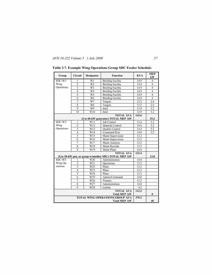
AFH 10-222 Volume 5 1 July 2008 57
Table 3.7. Example Wing Operations Group SDC Feeder Schedule.
Group Circuit Designator Function KVA MEP
kW
SDC-W1:
Wing Operations
1 W1 Briefing Facility 14.9 4
2 W2 Briefing Facility 14.9 4
3 W3 Briefing Facility 14.9 4
4 W4 Briefing Facility 14.9 4
5 W5 Briefing Facility 14.9 4
6 W6 Briefing Facility 14.9 4
7 W7 Targets 13.2 2.4
8 W8 Targets 13.2 2.4
9 W9 Intel 13.9 3.2
10 W10 Intel 13.9 3.2
TOTAL kVA
(Use 60-kW generator) TOTAL MEP kW
143.6
35.2
SDC-W2: Wing
Operations
1 W11 Job Control 13.4 3.2
2 W12 Material Control 14.4 3.2
3 W13 Quality Control 14.4 3.2
4 W14 Command Post 14.0 3.2
5 W15 Maint Supervision 13.2
6 W16 Maint Supervision 13.2
7 W17 Maint Analysis 13.2
8 W18 Maint Records 13.2
9 W19 Maint Plans 14.4
TOTAL kVA
(Use 30-kW gen. or group w/another SDC) TOTAL MEP kW
123.4
12.8
SDC-W3:
Wing Op-
erations
1 W20 Administration 14.0
2 W21 Operations 13.2
3 W22 Plans 13.2
4 W23 Plans 13.2
5 W24 Plans 13.2
6 W25 Admin/Command 14.0
7 W26 Finance 13.2
8 W27 Administration 14.0
9 W28 Latrine 4.2
TOTAL kVA
Total MEP kW
112.2
0
TOTAL WING OPERATIONS GROUP kVA
Total MEP kW
379.2
48

AFH 10-222 Volume 5 1 July 2008 58
3.4.9.1. This specific example shows that all circuits were kept within the
capacity of a 150 kVA SDC and that similar facilities/functions with mission
essential power requirements grouped together on two SDCs.
3.4.9.2. The 35.2 kW mission essential power load for SDC-W1 could be
supported with a 60-kW emergency/back-up generator. The 12.8 kW on
SDC-W2 could be supported with a 30-kW emergency/back-up generator, or
the facilities and SDC could be sited near another group so that both groups
could be fed from the same SDC and 60 kW emergency/back-up generator.
3.4.10. The feeder schedule for each group should be used to develop a cir-
cuit schematic to list the required connections. While the surveyors are de-
termining the rough layout of major facility groups, the circuit schematics
can be annotated to show concerns for a specific layout. Identify the basic
distances and locations for placement of SDCs next to the major facilities
and the circuits requiring emergency/back-up generators for the initial opera-
tion of the base. Critical base facilities may have to operate from emergen-
cy/back-up generators, linked by SDCs, for up to two weeks while assets
arrive and the main electrical distribution system is installed. The schematics
can be used to show and explain how facilities are located in proximity to
SDCs and emergency/back-up generators. They can also be used to flag the
need for a emergency/back-up generator at critical facilities where a load on
the generator would be so low that it should be shared with critical facilities
in another group – thus affecting the siting within two groups. Figure 3.13
depicts an example SDC Circuit for a Wing Operations Group at a 3,300-
person expeditionary base.

AFH 10-222 Volume 5 1 July 2008 59
Figure 3.13. Example SDC Circuit for Wing Operations Group.
3.4.11. Phase Balancing. To operate a power plant or generator efficiently,
the load on all three phases of the system must be nearly equal. The differ-

AFH 10-222 Volume 5 1 July 2008 60
ence between phases should not exceed 10 percent; otherwise, generators
will be out of balance and not provide full output. Also, voltage regulation
will be poor, which can damage both generating equipment and equipment
being powered. Even after all load factors are known and system schematics
developed, the system might require further balancing (smaller MEP genera-
tors are especially vulnerable to this condition when connected to critical or
isolated facilities). When laying out loads other than three-phase, take into
account the total loading on each phase. Equally distribute the facility loads
on an SDC by alternating which phase each facility is connected to on the
PDP (e.g., facility W1 connected to 25-kW PDP connector J5 [phase C], W2
connected to J6 [phase B], W3 connected to J7 [phase A], etc.).
3.4.12. Radial versus Loop. Radial systems are normally used during initial
stages of a deployment or for smaller austere bases (i.e., 1,100-persons) in a
low threat environment. Otherwise, plan to use a loop system, as they pro-
vide more reliable power, better system grounding, and greater flexibility for
handling everyday type power demands and maintenance outages. The #1/0
aluminum, 5,000-volt primary cable, and associated load break elbow con-
nectors, are used to interconnect the power plants and provide both adequate
insulation and mechanical integrity when buried to the proper depth. The
cable‘s wrapped concentric neutral provides additional grounding potential
and generally ensures that if damaged by weapons or equipment, a short cir-
cuit will occur at the point of contact, causing a fuse to blow at the PDC, or
the circuit to open at the PSC, eliminating a lethal threat to personnel res-
ponding to repair the cable.
3.4.13. Power Plant Dispersal. Plan to construct multiple power plants in a
high-threat environment (where facility dispersal is required) and for larger
deployments (2,200-persons or more). Power plant dispersal does not require
greater separation of equipment and controls within the plant. Protection of
resources is provided through the use of revetments, barriers, concertina
wire, CCD, and berms. Plants should be interconnected to ensure some de-
gree of electrical generation capability is retained after an attack. For threat
dispersal purposes, plants should be separated between 1,500 and 3,000 feet

AFH 10-222 Volume 5 1 July 2008 61
from each other as part of a loop electrical distribution network. The primary
method of looping is by interconnecting some PSCs/PDCs between plants.
3.4.13.1. To establish a looped system, a physical connection is made from
the output bushings of one PSC/PDC to the input bushings of another.
3.4.13.1.1. In Figure 3.14, the energized cables of PSC/PDC A are con-
nected to the input side of PSC/PDC B. Make sure that correct phasing is
maintained and concentric grounds are properly connected.
Figure 3.14. Typical Connection between Two PDCs.
Warning
Ensure interconnecting cables are marked
properly and maps are updated to show in-
terconnecting cables to ensure future rota-
tions are aware of these cables.

AFH 10-222 Volume 5 1 July 2008 62
3.4.13.1.2. Larger beddowns may have two or three plants with more than
one PDC. In this case, there are greater opportunities to loop between each
separate plant and interconnect several PSCs/PDCs to form a complete ring
between three or more plants.
3.4.13.2. Plants can also be interconnected through feeder circuit SDCs in an
unenergized (parked) status.
3.4.13.2.1. In Figure 3.15, PSC/PDC A feeds SDCs 1, 2, 3, and 4 while
PsC/PDC B feeds SDCs 5, 6, 7, and 8. The unenergized cables from SDC 1
to SDC 5 are placed on parking stands; next to a set of output bushings on
SDC 1 and next to a set of input bushings on SDC 5.
Figure 3.15. Parked Cables between Two SDCs on Different Circuits.
3.4.13.2.2. If the power plant serving PSC/PDC B, or PSC/PDC B itself,
were put out of service, PSC/PDC B would be isolated. Then the cables be-
tween SDCs 1 and 5 would be removed from the parking stands and placed

AFH 10-222 Volume 5 1 July 2008 63
on the respective output and input bushings to energize some of the SDCs
served previously by PSC/PDC B.
3.4.13.2.3. If PSC/PDC A were put out of service instead of PSC/PDC B,
reverse the SDC output and input bushing connections on the interconnect-
ing cables for the two SDCs.
3.4.13.3. Overload Prevention. When rerouting PSC/PDC feeder circuits to
power additional SDCs, care must be taken not to overload the circuit.
3.4.13.3.1. Additional cables may have to be run from SDCs on an opera-
tional PSC/PDC circuit to avoid overloads (Figure 3.16). Some of the SDC
feeder circuits, which were previously on the inoperative PSC/PDC circuit,
may also have to be rerouted.
Figure 3.16. Rerouting Cables to Prevent PDC Overloading.

AFH 10-222 Volume 5 1 July 2008 64
3.4.13.3.2. This would normally be done at the time of failure, but planning
for alternate SDC to SDC connections should be considered when laying out
the systems and utility corridors.
3.4.13.3.3. Always ensure correct phasing, concentric grounds properly con-
nected, and rerouted circuits do not overload the PSC/PDC.

AFH 10-222 Volume 5 1 July 2008 65
Chapter 4
INSTALLATION
4.1. Safety Summary. As noted in paragraph 1.1, electricians and mainten-
ance personnel shall wear appropriate arc thermal performance value
(ATPV) rated, as well as other appropriate, personal protective equipment in
accordance with AFI 32-1064 and UFC 3-560-01 prior to working on or
near energized electrical equipment or circuits. BCE or commander approval
is needed prior to working on any energized circuits. The following para-
graphs are recommended safety precautions that personnel must understand
and apply during many phases of operation and maintenance of contingency
electrical generation and distribution systems.
4.1.1. Only qualified individuals shall install, operate, and maintain the
equipment described in this handbook. A qualified person is one who is
trained and competent in:
4.1.1.1. The skills and techniques necessary to distinguish energized parts
from non-energized parts of electronic and electrical equipment.
Warning
Ensure loadbreak elbows are installed on
parking stands at PSC/PDC and generator
when performing maintenance to prevent
possibility of utility power being fed back
into equipment. Failure to comply may re-
sult in death by electrocution.
Warning
High voltage may cause severe shock or
death upon contact. Use caution and avoid
contact with energized components. Use a
hot stick when handling loadbreak elbows.

AFH 10-222 Volume 5 1 July 2008 66
4.1.1.2. The skills and techniques necessary to determine the proper ap-
proach distances corresponding to the voltages to which the qualified person
will be exposed.
4.1.1.3. The proper use of the special precautionary techniques, personal
protective equipment, insulating and shielding materials, and insulated tools
for working on or near exposed energized parts of electronic or electrical
equipment.
4.1.2. Keep away from live circuits. Operators must at all times observe all
safety regulations. Do not replace components or make adjustments inside
the generator set with the high-voltage supply energized. Under certain con-
ditions, dangerous potentials may exist when the generator is not operating
and disconnected from the circuit due to charges retained by capacitors. To
avoid casualties, always remove power and then discharge, ground, and test
a circuit before touching.
4.1.3. High-Voltage Cable Connections and Disconnects. Always operate
and connect generators, PSC/PDC, and SDCs in accordance with the appli-
cable T.O.s. Only properly trained and qualified 3E0X1 Electrical Systems
personnel should connect and disconnect this equipment.
4.1.3.1. Disconnects should be made in an de-energized state, which is nor-
mally achieved by shutting down the power source to the PSC/PDC, remov-
ing the arc strangler switches (during an emergency disconnect—see below)
on a PDC circuit, opening the load-interrupter switches on a PSC, or turning
off circuit breakers on an SDC. De-energized cables and transformers should
be grounded to prevent a shocking hazard from residual voltages.
Warning
Always make load break elbow connections
in a de-energized state.

AFH 10-222 Volume 5 1 July 2008 67
4.1.3.2. During placement of the units (i.e., PDCs, PSCs, SDCs, and PDPs)
and cable laying prior to bringing generators on line, when it is known that
electrical systems are de-energized, some connections can be made using
gloved hands. This can also be done for parking cables. However, use of a
hot stick for placing the load break elbows on bushings is always a good
safety practice to ensure proper seating of the load break elbows.
4.1.3.3. Safety and electrical equipment, including personal protective
equipment (PPE), must be used when connecting and disconnecting load
break elbows, opening PSC load-interrupter switches, arc strangler switches,
and fusible switches.
4.1.4. Do not service or adjust alone. Under no circumstances should any
person reach into or enter the housing for the purpose of servicing or adjust-
ing the generator set except in the presence of someone who is capable of
rendering aid.
4.1.5. Resuscitation. Personnel working with or near high voltages should be
familiar with modern methods of resuscitation. Cardiopulmonary resuscita-
tion procedures are contained in T.O. 31-1-141 and annual refresher training
requirements are outlined in AFOSH STD 91-10. Such information may be
obtained from base/post medical services.
4.2. Personnel Responsibilities. Multi-skilling of power production and
electrical personnel is critical for installation and operation of contingency
power generation and distribution systems. Neither power nor electrical spe-
cialties have sufficient numbers of personnel on standard mobility teams to
accomplish all beddown and recovery tasks following traditional skill brea-
kouts. Contingency training programs direct several training activities meant
to enable engineer personnel to perform beyond traditional peacetime-related
skill requirements. In the context of power plant and electrical distribution
system installation and operation, Table 4.1 highlights the responsibilities of
power production and electrical personnel:

AFH 10-222 Volume 5 1 July 2008 68
Table 4.1. Task Responsibilities.
Task Primary AFSC Secondary AFSC
Set Up Power Plant Power Production Electrical
Operate Power Plant Power Production Electrical
Set Up Distribution System Electrical Power Production
Connect Tactical Generators Power Production Electrical
Install RALS Electrical Power Production
Phase/Parallel Generators Power Production Electrical
Install Grounding System Electrical & Power
Set Up Telescopic Light Set Electrical & Power
Construct Revetments Electrical & Power
Make/Break High Voltage Connections Electrical
4.3. Grounding. Proper grounding of the electrical system is crucial for the
safety of electrical power production and electrical system personnel. Proce-
dures for grounding the deployable systems differ little from those used in
standard electrical system installations. The grounding system for the con-
tingency electrical generation and deployable system equipment consists of
equipment grounds with ground rods at major components and the
(grounded) concentric neutral wires throughout the high-voltage distribution
portion of the system.
4.3.1. All equipment shall have a grounding resistance that does not ex-
ceed 25 ohms. Test grounds IAW Chapter 10, Section III of AFJMAN 32-
1082, Facilities Engineering – Electrical Exterior Facilities.
Warning
Do not energize equipment unless properly
grounded. Electrical faults in generator set,
load lines, or load equipment can cause in-
jury or electrocution from contact with an
ungrounded system.

AFH 10-222 Volume 5 1 July 2008 69
4.3.2. Soil characteristics play a large part in the suitability of the grounding
network. The type of soil, its chemical content, and the moisture level sur-
rounding the ground rod will determine the resistance. Clay and loam soils
with no rocks or stones will have a much lower resistance than clay or loam
soils with many rocks or stones. Moisture content also affects resistance
readings dramatically. As moisture content increases, soil resistivity decreas-
es. This is especially true at the lower moisture content levels. Therefore,
much of the dry, rocky, or sandy soils in SWA cannot provide the required
soil resistivity of 25 ohms or less using just the driven ground rods provided
with each unit.
4.3.3. For proper grounding, you must have a ground rod that will be in con-
tact with moist soil. Use as many ground rods as required to obtain adequate
resistance readings. If deployed to a location where a ground rod cannot be
driven deep enough to reach low resistance soil, or if ground rods are in
short supply, then alternate-grounding methods must be used. A horizontal
ground rod installation (Figure 4.1), buried metal well pipes, metal plate
electrodes, or a laced wire grounding installation (Figure 4.2) can be used to
obtain the adequate resistance reading. Dig a trench as deep as feasible to
reach wet soil or soil that can be moistened with water or brine. Lace a cop-
per wire up and down the bottom of the trench. To keep resistance readings
low under extremely adverse soil conditions, you may have to continuously
keep the grounding area damp using water or salt water/ROWPU brine solu-
tions. Thoroughly compact the soil when backfilling the trench to maximize
soil contact with the wire or rods.
Figure 4.1. Typical Equipment Horizontal Ground Rod Installation.

AFH 10-222 Volume 5 1 July 2008 70
Figure 4.2. Typical Equipment Laced Wire Grounding Installation.
4.3.4. For longer deployments, installation of a grounding grid (Figure 4.3)
under each equipment item (i.e., generator, PSC/PDC, SDC, etc.) should be
considered both for additional safety and reliability. Each equipment item
should have its own equipment ground and rely on the concentric neutral
wires within the three connecting high-voltage cables to provide continuity
for both electrostatic and system grounding.
Figure 4.3. Typical Equipment Grounding Grid Platform Installation.
4.3.5. If deployed to a location in a climatic zone where the ground freezes,
be sure to lay the horizontal grounding system below the frost line, as resis-

AFH 10-222 Volume 5 1 July 2008 71
tivity readings can increase substantially for frozen ground. Also, frost
heaves that occur in soil with different moisture contents may cause equip-
ment to tilt or move if the buried horizontal rod or wire system is located too
close to the equipment. Keep the disturbed, moistened soil of the buried
grounding system at least 10 feet from the supported equipment. The groun-
ding system should normally be within 15 feet of the supported equipment;
this is not a hard and fast rule and is dictated more so by the available area
and materials and the ability to obtain and maintain adequate resistance read-
ings. For driven ground rods, recheck the resistance readings regularly
throughout the deployment.
4.4. DPDGS High-Voltage Component Installation.
4.4.1. MEP-12A. See Chapter 5 for power plant equipment installation pro-
cedures.
4.4.2. Primary Switch Center. See Chapter 5 for power plant equipment
installation procedures.
4.4.3. Secondary Distribution Center (SDC).
4.4.3.1. Site Preparation. Use the following general guidelines for installa-
tion site preparation.
4.4.3.1.1. The installation site should be a relatively level surface capable of
bearing the weight of the SDC. The area surrounding the SDC should have
enough slope to allow for drainage; limit ground slope to about 1% unless
faster drainage is required.
4.4.3.1.2. Clear the site of brush, large rocks, and other items that might in-
terfere with the operation, maintenance, access to, door openings to provide
clearance for use of hot sticks, or stability of the unit.

AFH 10-222 Volume 5 1 July 2008 72
4.4.3.1.3. Ensure there is unobstructed airflow to the outside vents to allow
cooling of the transformer. Clear the area within 6 feet above and 10 feet on
the sides of the unit.
4.4.3.1.4. If possible, make use of terrain features to minimize the heat loads
on the SDC by placing the unit in shady areas.
4.4.3.1.5. Ensure cables are trenched for protection and safe operation.
4.4.3.2. Grounding.
4.4.3.2.1. One ground rod (in two 4-foot sections) and six feet of bare,
stranded copper wire is shipped with each SDC. The ground rod is stored in
the high-voltage compartment door.
4.4.3.2.2. Remove ground rod from high-voltage compartment door and
drive within 5 feet of high-voltage side of SDC (Figure 4.4).
Figure 4.4. SDC Ground Rod Assembly.
4.4.3.2.3. Locate the section that has threads on one end and is pointed on
the other. Attach the other section to the first with a coupling. Drive the as-
sembly into the ground, pointed end first, until approximately four to six
inches is left above the ground.
4.4.3.2.4. Attach the copper wire to the exposed end of the ground rod by
securing the wire with the ground rod clamp provided.
4.4.3.2.5. Test for ground resistance IAW Chapter 10, Section III of
AFJMAN 32-1082.

AFH 10-222 Volume 5 1 July 2008 73
4.4.3.2.6. Attach the loose end of the ground wire by feeding through the
opening at the bottom of the high voltage compartment (Figure 4.5) to a
ground bus connection located at the bottom left side on the front face of the
primary mounting panel.
Figure 4.5. Grounding Location on the SDC.
4.5. HARVEST Series High-Voltage Component Installation.
4.5.1. MEP-12A. See Chapter 5 for MEP-12A installation procedures.
4.5.2. PDC. See Chapter 5 for PDC installation procedures.
4.5.3. SDC. The Harvest Falcon SDC is installed in the same manner as the
DPGDS SDC. Use the procedures in paragraph 4.4.3.

AFH 10-222 Volume 5 1 July 2008 74
4.6. Laying Out High-Voltage Cable. High-voltage, primary power is dis-
tributed on #1/0 aluminum, 5,000-volt, cross-linked polyethylene cable with
wrapped concentric ground wires (Figure 4.6). It is of the optimum size for
load requirements and provides both adequate insulation and mechanical
integrity when buried to the proper depth. The drain wires in the cable jacket
generally ensures that if personnel hit the cable with digging devices, a short
circuit will occur at the point of contact, blowing a fuse at the PDC and
hopefully avoiding injury to personnel.
Figure 4.6. Primary Cable Cross-section.
4.6.1. Mark the high-voltage cables according to phase and secure the free
cable ends to some solid object at or near the power source. Leave a service
loop to connect to the output terminals of the power source.
4.6.2. Load the cable reel pallet assembly on a forklift or suitable truck and
move the vehicle slowly along the predetermined cable route allowing the
cable to pay out freely. When nearing the end of the cable path, decelerate
slowly to minimize cable reel spin.
Warning
Excessive speed of cable-laying vehicle can
cause cable reels to keep spinning after ve-
hicle stops. Attempting to stop reels can
cause serious injury to personnel.

AFH 10-222 Volume 5 1 July 2008 75
4.6.3. Cut cabling to length and mark the end of the cables according to
phase.
Note: To permit the flexible movement of the feeder cables between the
PDC online bushings and the parking stands once the cables are entrenched,
it is imperative that all cable entrenchments approach the PDC parallel to the
side where cables are connected (Figure 5.21).
4.7. Trenching. During the initial layout and early operation, the electrical
distribution network is an above ground system. When time permits, bury
the primary distribution electrical lines in trenches about 18-inches deep.
4.7.1. The trenches should be wide enough to provide a 6-inch separation
between cables. Cables should not be laid directly on sharp rocks or in very
rocky soil; where such rocks are present, place a layer of sand or other soil
free of sharp rocks on the bottom of the trench. If the soil is very rocky and
the area will be trafficked, then a layer of sand or rock free soil may be also
be required above the cables.
4.7.2. At locations where cables cross roadways and in high-traffic areas, the
lines should be buried even in the initial phases of the operation. Considera-
tion should be given to running the lines in conduit under roadways and bu-
rying the cables deeper to allow improving roads over these cables with
gravel or hard surface. Secondary distribution lines for service from SDCs
should also be buried (when time permits) in shallower trenches. Under most
climactic conditions, secondary distribution lines require only 8 inches of
cover, except for the following conditions:
4.7.2.1. For desert conditions, heat will degrade both primary and second-
ary cable; ensure that the cable has at least 12 to 16 inches of cover.
4.7.2.2. In areas subject to ground freezing, bury cables below the frost line.
4.7.2.3. In locations which may experience numerous freeze-thaw cycles
throughout the winter (where there is intermittent flooding and ground

AFH 10-222 Volume 5 1 July 2008 76
movement), buried cannon plug cable connections may require some water-
proofing protection (i.e., wrap in plastic sheeting and tape) or be surrounded
with free draining sandy gravel. If winterizing procedures are required for
the deployment, marking or otherwise identifying buried cannon plug con-
nections at critical facilities will allow them to be checked if freeze-thaw
cycles cause problems with electrical connections.
4.7.3. Most trenching is accomplished using a tractor with backhoe and
blade. The attachments are removable and/or interchangeable. Upon arrival
at the deployment location, the Civil Engineer‘s tractor may arrive confi-
gured with or without a rotary-trenching wheel (Figure 4.7), which is nor-
mally associated with Communication‘s configuration of the tractor. If the
equipment arrives with the rotary-trencher, the rotary-trencher may be re-
moved or used by Civil Engineers for burying secondary or primary distribu-
tion cables. Expect to have some handwork when burying cable near
generators, PSCs/PDCs, and SDCs.
Figure 4.7. Tractor with Backhoe, Blade, and Trenching Wheel.
4.7.4. It is especially critical to maintain the 6-inch separation (Figure 4.8)
for primary power cables and to keep the cable from bundling together in the
trench for facilities that require more reliable power and for interconnecting
power plants. If a rotary-trencher is used, maintaining adequate separation
will be difficult due to the narrow width of the trench. Field conditions may
dictate various installation choices, which can be used to maintain a 6-inch

AFH 10-222 Volume 5 1 July 2008 77
separation and also meet required cover and protection, such as multiple
trenches with a wheel cutter trencher, wider trenches, and/or deeper trenches
and cable laid with horizontal and a vertical separation between cables.
Figure 4.8. Trench and Cable Detail.
4.7.5. In the immediate power plant area, make sure the trenches are clearly
marked to ensure that future additional trenching operations will not hit bu-
ried power cables. Plan ahead, especially when multiple power plants are
used, to provide access for routing of cables between plants. In some cases it
may be feasible to bury several sets of power lines in wider and deeper
trenches (Figure 4.9) to accommodate base growth and/or expansion of the
power plant.

AFH 10-222 Volume 5 1 July 2008 78
Figure 4.9. Multiple Cable Runs in Common Trench.
4.7.6. Keep accurate, up-to-date records on the location of power lines and
when possible, mark the cable routes. Cable routes between plants can be
relatively long, traversing much of the camp area. During long-term deploy-
ments, trenches can become overgrown or covered by blowing sand. If they
do not have accurate records, follow-on units can easily disrupt electrical and
other utilities when trenching to expand or repair/replace systems.
4.7.7. When burying cable, be sure to label SDCs with feeder and SDC
numbers. These numbers should accurately match the as-built drawings for
troubleshooting and safety purposes. When time permits, label the cable to
show where it feeds and from where it is fed (Figure 4.10).
4.8. Fabrication for Load Break Elbows. Cables are cut to length in the
field and load break elbows are used as connectors. Load break elbow as-
semblies vary based on the model used. Follow appropriate technical orders
or manufacturer‘s installation instructions if available. If specific model in-
structions are not available, see Attachment 2 for general instructions.
4.9. Cable Connections from Generators to PSC/PDC. After laying out
and locating equipment for the power plant(s), fabricate all three phases of
cable connections between the generators and the PSC/PDC. Ensure 3 to 4
feet of concentric ground wire is available for each cable. Verify that cabling
at and between the generator and the load is in serviceable condition, pro-
tected from vehicle traffic or other possible sources of damage, and that the

AFH 10-222 Volume 5 1 July 2008 79
cable phasing is maintained. See Chapter 5 for detailed cable connections
between generators and PSC/PDC.
Figure 4.10. Feeder Circuits Labeled.
Warning
Do not apply primary power to the SDC until
all post-installation checks have been satisfac-
torily completed.
Warning
Ensure all power is removed from the primary
power cables before attempting to attach or
detach the loadbreak elbows. Disconnect
cables at source if not already disconnected.
Lethal voltages may be present.

AFH 10-222 Volume 5 1 July 2008 80
4.10. Connections from SDCs to PSC/PDC.
4.10.1. A single SDC can accept a three-wire high-voltage input from a ge-
nerator, PDC, PSC, or another SDC. The high-voltage cables are connected
to an SDC with load break elbows. This is always the case whether the
cables are coming from a PDC, PSC, generator, or from another SDC. Load
break elbows are connected and disconnected using a Grip-All Clamp Stick.
Disconnects must be made in a de-energized state.
4.10.2. The input side of the SDC has three switches, each of which has three
poles; each center pole is an EFD switch (Figure 4.11). With each center
poll removed, the SDC will not provide power to the low-voltage output
circuits, but will still transfer (through the high-voltage bus) high-voltage
power to any other SDCs connected through the output bushings (Note:
When laying out and connecting the system, the EFD center poles for each
SDC should be removed until all the individual SDC circuits are to be ener-
gized). The center poles are connected/disconnected with a switch stick
(Figure 4.12). The outer poles may also be removed, but must be reinstalled
before the system is energized. Do not attempt to make an energized con-
nection of the outer poles.
Warning
Failure to observe the warnings above may
result in danger to operating personnel and/or
serious damage to the equipment.
Warning
Pulling the center electric fusible disconnect
(EFD) will not de-energize any cable inter-
connecting SDCs in the circuit. This will only
de-energize the transformer on the SDC from
which the EFD was removed.

AFH 10-222 Volume 5 1 July 2008 81
Figure 4.11. Detail of Electric Fusible Disconnect (EFD).
Figure 4.12. Disconnecting EFD Center Pole with a Switch Stick.
4.10.3. When facing the high-voltage end of the SDC, the commonly used
input connection bushings are on the left side of the panel face. For initial
installation, pull the ends of the primary cables through the floor opening
into the high-voltage compartment. Install the load break elbows in accor-
dance with manufacturer‘s instructions and place on the respective phase
parking stand. Connect the concentric neutral wires from each cable to the
lug terminals on the ground bus plates at the bottom of the panel face
(Figure 4.13).

AFH 10-222 Volume 5 1 July 2008 82
Figure 4.13. SDC Input Ground Connection.
4.10.4. Before connecting the cables to the SDC, remove the center pole of
each of the three EFD switches by sliding it out of the EFD switch using a
hot stick. This isolates the SDC transformers from an incoming power
source, which affects only the low-voltage power outputs. Verify that cor-
rect fuses are in the center pole of each of the three input EFD units of the
SDC and that all fuses are firmly in place in the fuse clips. Leave the center
pole sections of the EFD units out until after circuit checkout.
4.10.5. Remove red loadbreak protective shipping caps on input connectors
for later use. Clean connectors with a rag.
Caution
While bushings come with ID markings as
input connections and have proper phase iden-
tified on adjacent nameplates, some markings
and/or nameplates may become illegible from
wear. Ensure all operators are fully knowled-
geable of equipment functions and features
when making connections.

AFH 10-222 Volume 5 1 July 2008 83
4.10.6. Lightly coat the bushing well insert and loadbreak elbow with dielec-
tric silicone grease and connect cables from high-voltage sources to the
bushing well inserts on the high-voltage side of the SDC (Figure 4.14) en-
suring no phase cross-connections.
Figure 4.14. Cables Connected to Input Bushings.
4.10.7. Cover unused SDC bushing well connectors with 15kV protective
insulated caps prior to energizing.
4.10.8. See paragraph 5.8.3.2 to connect wires to PDC output connectors.
4.10.9. Once connections are made on the load side of the SDC and post-
installation checks are completed, the EFD center poles can be reinstalled.
4.10.10. Additional SDCs may be interconnected to an SDC connected di-
rectly to the primary power source. To interconnect SDCs, layout primary
cable between the SDCs to be interconnected and connect the concentric
grounds to the ground buses. Connect the load break connectors of the addi-
tional SDC to the bushing wells marked INPUT CONNECTOR øA, øB, and
øC. Then install load break connectors in the bushing wells marked
OUTPUT CONNECTOR øA, øB, and øC in the SDC connected to the pri-
mary power source. Using this interconnection plan, each SDC can deliver
primary power to two additional SDCs (Figure 4.15).

AFH 10-222 Volume 5 1 July 2008 84
Figure 4.15. SDC Input and Output Cables.
4.10.11. Make sure proper phase order is maintained for all equipment con-
nections in the system and concentric ground wires are connected at both
ends of all PDC-to-SDC and SDC-to-SDC cabling. After the SDCs have
been installed on a PDC circuit, the system circuit can be energized.
4.10.12. As mentioned in paragraph 2.2.5.1, when only one MEP-12A is
required for a limited area and there is no available PDC, several SDCs may
be branch-connected together to sufficiently distribute high-voltage power
(Figure 4.16). Theoretically, five SDCs can be connected in this manner to
distribute high-voltage power; however, such an installation will provide a
lower degree of safety for the generator than with the use of a PDC.
Caution
Standard SDC configuration with EFDs only
in center pole position does not provide over-
current protection back to the generator.

AFH 10-222 Volume 5 1 July 2008 85
Figure 4.16. Branch Connected SDCs with a MEP-12A Generator.
4.10.13. Managing loads coming from such an SDC branched distribution
system should be done only by experienced personnel who are qualified to
make PDC connects and disconnects, as the overall branched system will be
functioning as a PDC. Unlike the PDC, which has fuses and disconnect
switches, the SDC has only outer switch poles, which can be removed.
However, there is no recommended procedure to allow high-voltage,
emergency energized disconnects for the SDC. This secondary (load) sys-
tem is intended to be de-energized before pulling outer poles with a hot stick.
4.11. Connections from SDCs to PDPs and Service Panels. Individual
feeder circuits from the SDCs are run from feeder receptacles (using cannon
plugs) along 50-foot and 100-foot cables. They connect to either facility
power distribution panels (PDP) (Figure 4.17), shelter electrical service pa-
Warning
Do not connect secondary cable assemblies
to SDC output receptacles until installation
of entire system and completion of post in-
stallation checks. Powered cables represent
a shock hazard to installing personnel.

AFH 10-222 Volume 5 1 July 2008 86
nels (Figure 4.18), or specific equipment items with compatible cannon plug
connections (example, ECUs and RALs). Power may also be run to an ECU
from the served PDP (Figure 4.19) or shelter electrical service panel. Note:
Be sure to start with plug (male) end of cable assembly at the SDC, and
leave enough cable at the SDC to permit insertion into output receptacle.
Figure 4.17. Connection from SDC to Small Shelter System PDP.
Figure 4.18. Cannon Plug Connection from SDC to ESC Service Panel.

AFH 10-222 Volume 5 1 July 2008 87
Figure 4.19. Connection from PDP to ECU.
Caution
When making short cable runs with a long
cable, DO NOT coil energized excess cable.
Magnetic lines of flux across the coils will
cause the cable to heat up and burn.
Caution
Cable runs over 400 feet may exceed max
allowable voltage drop. Ensure that voltage
at load does not drop below 10% of original
voltage.
Warning
Coiled secondary cables are heavy. Get help
when necessary and lift carefully by bend-
ing at the knees to prevent injury.

AFH 10-222 Volume 5 1 July 2008 88
4.11.1. Some PDPs, shelter service panels, and/or ECUs may not have a
cannon plug receptacle. In those cases, hard wire the service connection from
the SDC.
4.11.2. Be aware that the PDPs also have external ground lugs on their
frames for grounding of the units. In desert locations, it may not be possible
to provide an adequate ground for every small facility PDP due to the soil
conditions. However, larger PDPs such as the 60 kW, 100 kW, and 200 kW
units that serve as major distribution centers for large facilities, several fa-
cilities, or facilities with numerous major equipment items, must have a sep-
arate ground at each PDP. This is especially important in climate areas with
high-moisture levels.
4.11.3. If the larger PDPs are connected to a smaller MEP generator, which
must be hard-wired, then the generator input connection on larger PDPs may
also have to be hard wired. Check the manufacturer‘s model and T.O. for
any safety cautions or warnings that may be applicable for the unit.
4.11.4. The secondary cables for low-voltage power from the PDPs are con-
nected with NEMA type twist-lock plugs to individual facility distribution
and lighting strips.
4.11.5. Do not make an energized low-voltage connection with cannon plugs
when connecting a cable to an SDC, a cable to a cable, a cable to a PDP, or a
facility service panel connection. Before making a connection, turn off
power to the cables at the individual branch circuit breakers of the
SDC. Check to ensure that individual circuit breakers for facilities and PDPs
are also off during connections from SDCs to PDPs or facility panels. This
will prevent surging on a circuit, and will ensure that if there is a problem
with any one circuit coming out of a service type panel, the problem can be
more quickly identified.
4.12. Mission Essential Power. If it is necessary to provide power to mis-
sion essential loads before the prime power grid is energized, and/or emer-
gency power after the grid is energized, install the emergency/back-up cable

AFH 10-222 Volume 5 1 July 2008 89
assemblies at this point. Each SDC can be connected to an emergency/back-
up generator.
4.12.1. Set up the emergency/back-up generator near the SDC and connect
the mission essential loads to the secondary output connectors on the SDC
(Figure 4.20). Ensure all SDC output circuit breakers are OFF.
Figure 4.20. SDC Secondary Connection Panel and Circuit Breakers.
Warning
Do not energize the emergency/back-up gene-
rators until post-installation checks have been
made (mission essential mode) for the SDC,
the secondary cable assemblies to the affected
loads, and the loads themselves. Failure to
complete post-installation checks may result
in danger to installing personnel.

AFH 10-222 Volume 5 1 July 2008 90
4.12.2. Connect the generator cable assembly to the emergency/back-up ge-
nerator and SDC and perform post-installation checks necessary to ensure
safe operation of equipment in the mission essential mode.

AFH 10-222 Volume 5 1 July 2008 91
Chapter 5
POWER PLANT INSTALLATION
5.1. Introduction. Using the planning factors in Chapter 3, set up and
layout the power plant. Adhere to the safety requirements in Chapter 4
when setting up the power plant. In laying out the system, your primary con-
cern will be supplying electric energy at voltages necessary to operate the
end user‘s equipment. Electric power from host nation sources is used if
available, unless inadequate or subject to frequent interruption. On deploy-
ments where it is not possible to connect to host nation commercial sources,
Mobile Electric Power (MEP) generators are used.
5.2. Site Selection. When selecting a location to set up a power plant, con-
sider factors such as topography, noise, and vehicle access.
5.2.1. Topography. The general location of the primary power plant is de-
termined by facility planners (primarily engineer officers and engineering
personnel) with input from electrical and power production personnel. If
dispersed plant operation is called for, all plant locations will be identified.
With general locations decided, specific sites can then be picked out by on-
the-ground physical inspection. In determining the specific sites consider the
following:
5.2.1.1. Ensure the area is large enough to accommodate all equipment assets
(e.g., generators, fuel bladders, berms, PSC/PDC, operator‘s shelter, etc.).
5.2.1.2. Plan for security fencing around plant perimeter (e.g., concertina
wire).
5.2.1.3. Look for relatively level land to minimize site preparation.
5.2.1.4. Plan to prepare extremely level ground for fuel bladders and PSC/
PDC locations.

AFH 10-222 Volume 5 1 July 2008 92
5.2.1.5. Check area for reasonable flooding and drainage patterns.
5.2.1.6. Ensure drainage ditches, swales, or irregular terrain does not inhibit
access to site.
5.2.1.7. If possible, allow trees on site to provide shade and some camouf-
lage, but not block airflow.
5.2.1.8. To minimize blowing dust and dirt, leave low ground cover undis-
turbed to the greatest extent possible
5.2.2. Noise Considerations. Site selection includes consideration of noise
generated by power plants. Planners normally take this into account by dis-
tancing power plants as far as possible from cantonment and administrative
type areas. In addition to distance, the use of tree lines and natural ground
contours between power plants and highly populated areas can reduce noise
interference. In barren regions, manmade revetments and baffles may also be
used as noise barriers. Lastly, when practicable, situate plants downwind of
high-use areas to use the prevailing winds to reduce the noise factor.
5.2.3. Vehicle Access. Of critical importance to primary power plant opera-
tion is vehicle access, particularly for larger trucks and heavy equipment.
Once a plant is established, large vehicles will still require access for deli-
very of operating supplies, repair parts, and fuel.
5.2.3.1. Sufficient space should be allowed to enable removal of an entire
generator unit for depot level repair without uninstalling plant equipment or
moving assets around.
5.2.3.2. Burial of electrical cables may be desired at a later time—it is much
easier to bring in a trenching machine than hand-digging hundreds of feet of
trench in desert hardpan or rock filled frozen earth. Leave space for trench-
ing equipment when future trenching in plant area is anticipated.
AFH 10-222 Volume 5 1 July 2008 93
5.2.3.3. If an extended contingency operation appears probable, it is advisa-
ble to build hard surface vehicle access ways at least to the refueling points.
If blacktop roads are not possible, go with soil-cement or gravel.
5.2.3.4. Be sure to consider fire-fighting access. Coordinate with the base
fire chief to determine realistic space requirements; different bases have dif-
ferent fire fighting vehicle sets. As a minimum, plan your plant layout to
allow complete accessibility to its entire perimeter.
5.3. Equipment Layout. Although the same basic equipment is used in all
Air Force contingency power plants, there are many possible equipment
layout configurations. These configurations are influenced by two basic fac-
tors—the size of the base population (determines quantities of assets re-
ceived) and whether dispersed or non-dispersed operations are required
(dictates number of plants to set up). Within these configurations, there is no
mandatory way to layout individual equipment items. Land area available,
vehicle access needs, available lengths of cable and piping, and, to some
extent, operational requirements will drive individual equipment item layout.
5.3.1. Power Plant Configurations. The following paragraphs describe the
operating scenarios, plant configurations, and the number of PSCs and PDCs
required for safe operation.
5.3.1.1. Power Plant Layout with PSC. One-, two-, and three-unit plants are
typically configured with one PSC. A four-unit plant requires the use of two
PSCs for safe isolation. See T.O. 35F14-1-1 for proper PSC relay settings.
5.3.1.1.1. Two-Unit Plant. Figure 5.1 illustrates a two-unit plant configura-
tion with a PSC and identifies the connections required to establish a com-
mon power bus. Disregard unit two in the figure if setting up a one-unit
plant.
5.3.1.1.2. Three-Unit Plant. Figure 5.2 illustrates the layout and connections
for a three-unit configuration.

AFH 10-222 Volume 5 1 July 2008 94
Figure 5.1. Two-Unit Plant with PSC Configuration.
Figure 5.2. Three-unit Plant w/PSC Configuration.

AFH 10-222 Volume 5 1 July 2008 95
5.3.1.1.3. Four-Unit Plant. A four unit plant configuration requires the use of
two PSCs. Figure 5.3 illustrates the connections for this configuration. The
PSCs are interconnected by 15KV 4/0 AWG, 600 amp Deadbreak, 35 feet
long cable assemblies that ship with the PSC. In addition, the adjustable fault
interruptors for Way-6 on both PSCs are programmed for 400 minimum
pickup amps. Note: A loadbreak connector is designed to close or interrupt
current on energized circuits. A deadbreak connector is designed to be sepa-
rated and engaged on de-energized circuits only.
Figure 5.3. Four-unit Plant w/PSC Configuration.
5.3.1.2. Power Plant Layout with PDCs. MEP-12 units may be configured as
a one-, two-, three-, or four-unit plant with one PDC. The typical four-unit
configuration with PDCs are shown in Figure 5.4. If setting up a plant with
less than four units, eliminate the number of units as necessary in the figure
starting with unit 4. When only one MEP-12A is required to provide power
to a limited area, the SDC may be used without a PDC to distribute power
from a MEP-12A through cables and load break elbows to other SDCs and

AFH 10-222 Volume 5 1 July 2008 96
users‘ power distribution panels (see paragraph 4.10.12). Figure 5.5 illu-
strates the typical MEP-12A power plant layouts by base population.
Figure 5.4. Four-Unit Plant w/PDC Configuration.
Figure 5.5. General Plant Configurations w/PDCs by Population.

AFH 10-222 Volume 5 1 July 2008 97
5.4. Generator Installation. Install generator on level ground with a mini-
mum slope for drainage, usually not to exceed 1%.
5.4.1. Positioning. Typically, MEP-12As are lined up parallel with each oth-
er and at least 20 feet apart. Generators must have a minimum clearance of
10 feet between units. They may be spaced wider apart to allow for addition-
al cooling, especially if prevailing winds have a range of directions. Up to 20
feet is used to allow for a range of wind directions. However, the wider the
units are spaced, the harder it is to keep them within the required 80 feet of
the PDC.
5.4.1.1. As is shown in Figure 5.6, the radiator-end of the generators are
positioned downwind of the prevailing winds, which aids in cooling by
blowing along the long axis of the generators. However, in extremely dusty
climates, the units can be oriented with the radiators toward the prevailing
winds to allow the radiator fan exhaust to blow the drifting dust away from
the radiators.
Figure 5.6. Generators Positioned with Radiators Downwind.
5.4.1.2. For long duration deployments in hot regions, consider building sun-
shades over the generator sets to reduce solar heat buildup. Maintain at least
a 2-foot clearance between the sunshade and the mufflers mounted on top of
the generator.
Caution
Fuel spillage can occur if the generator tilts
more than ± 2 degrees.

AFH 10-222 Volume 5 1 July 2008 98
5.4.2. Grounding. The MEP-12A is grounded at the front right (facing the
tow bar) corner of the unit at the ground stud (Figure 5.7). Connection to a
ground rod is made using either a #2 or #4 AWG copper wire. A second
ground lug is located at the power panel, which is tied into the current trans-
former and ground fault relay. While it is possible to connect the ground rod
wire to this terminal, normal practice is to connect to the front ground stud to
allow inspection of the ground connection. Both studs are bonded together
with a grounding cable. Note: Do not bond the ground rods of separate
generators together and do not ground them to a central ground.
Figure 5.7. Ground Stud on MEP-12A Generator.
5.5. Establish Fuel Storage/Manifold System. The external fuel systems
for the DPGDS and legacy systems are slightly different. Since there is a
chance that left over legacy systems were transferred to the BEAR sets, both
will be discussed in this handbook.
Warning
The fuel tank, even when empty, may con-
tain explosive fumes or vapors. Do not ex-
pose tank in the vicinity of any source of
intense heat. Smoking is prohibited within
50 feet of generators or fuel area. Failure to
heed this warning may result in death or
injury.

AFH 10-222 Volume 5 1 July 2008 99
5.5.1. DPGDS External Fuel Storage/Manifold System. Figure 5.8 illustrates
the major components of the collapsible fuel tank assembly. The external
fuel hoses for each generator are connected to the external fuel system‘s ma-
nifold (Figure 5.9). The manifold may be connected to a multiple sources of
fuel, e.g., bladder, truck, etc. Care must be taken to ensure that the electrical
cables are not in the proximity of the fuel lines. The external fuel system is
grounded separately from the generator grid.
Figure 5.8. 20,000-Gallon Fuel Bladder Assembly.
Caution
Ensure fuel lines are protected from electrical
cables and routed to minimize potentials for
physical damage and tripping hazards.
Warning
Use only containers designed to handle fuels.
Do not use near open flame, heat, or electrical
sparks. Avoid prolonged contact with skin or
eyes and avoid breathing fumes. Failure to
comply may result in serious injury or illness.

AFH 10-222 Volume 5 1 July 2008 100
Figure 5.9. DPGDS External Fuel Supply Layout.
5.5.1.1. Lay out fuel hoses between the generator, fuel manifold, and the fuel
bladders to establish the fuel supply system.
5.5.1.2. Install the external generator fuel hose at the fuel inlet connection on
the side of the unit (Figure 5.10) and the other end to the fuel manifold out-
lets (Figure 5.11).
Figure 5.10. Fuel Hose Connected to MEP-12A.

AFH 10-222 Volume 5 1 July 2008 101
Figure 5.11. Manifold Assembly.
5.5.1.3. Connect the 3-inch hose, with the quick-disconnect fittings, from the
fuel manifold to the fuel bladders.
5.5.1.4. Connect the fuel manifold ground wire to the ground grid and then
open only the appropriate fuel manifold valves to supply fuel to the power
units. Check for leaks at all connections and entire length of fuel hoses.
5.5.2. Legacy External Fuel Storage/Manifold System. The legacy system
has two 10,000-gallon fuel bladders weighing 230 pounds each for the MEP-
12A 4-unit plant. Bladders come in two sizes: 22 feet wide by 22 feet long or
12 feet wide by 42 feet long when unfolded from the shipping container.
When filled, the bladder is approximately 4 feet high and the measured foot-
print shrinks by about 1 to 2 feet in both directions.
5.5.2.1. There are two filler assemblies, one toward each end of the bladder,
that provide connections for fuel filling and discharge to the generators.
Bladders have three connections on the top surface—a filler assembly, a dis-
charge assembly, and a vent assembly. The vent assembly is simply a relief

AFH 10-222 Volume 5 1 July 2008 102
valve and standpipe, and is attached to the fitting on the center of the blad-
der. The remaining two connections are fitted with elbows. One elbow is
configured to adapt to fuel delivery vehicles, the other is connected to a ma-
nifold assembly (Figure 2.19) with a 3-inch hose. It is advisable to place a
sandbag under the 3-inch hose, about two feet out from the elbow, to reduce
stress on the bladder fitting connection. Two 1-inch lines leave the manifold
assembly and are attached to the generators (Figure 5.10). The manifold has
a pass through capability to allow fuel to be distributed to other manifolds.
Each generator has an internal pump to draw fuel; therefore, no external
pumps are necessary in the fueling hose assemblies. Only 50 feet of 1-inch
hose is provided with each generator, requiring storage bladders to be set up
relatively close to the generators.
5.5.2.2. When setting up a power plant, normally one bladder is provided for
every two MEP-12A generators. Figure 5.12 depicts the common placement
of the fuel bladder with respect to the generators.
Figure 5.12. Typical Fuel Bladder Placement.

AFH 10-222 Volume 5 1 July 2008 103
5.5.2.2.1. Generators should be located not closer than 100 feet from the fuel
bladders for flammability and fire protection purposes. Decreasing this dis-
tance to 50 feet (per AFPAM 91-216, Bare Base Construction Requirements)
may be done only with approval of fuels and fire protection personnel and
when adequate berming is provided.
5.5.2.2.2. The 1-inch diameter fuel lines are 25 feet long, requiring the mani-
folds to be within 25 feet of the generator fill ports, but still must have
enough slack to be moved and connected.
5.5.2.3. The ground under the fuel bladders requires preparation before blad-
ders can be positioned. An area 16 feet by 46 feet must be leveled to prevent
the bladder from ―creeping,‖ and any debris or sharp objects must be re-
moved. If sufficient material is available, a 4-inch thick sand bed should be
provided under the bladder. Provide a minimum 2-foot clearance around the
empty bladder as it is being laid out; the clearance area should be level. The
area under the filled bladder should have an even 1-degree slope from the
edges of the bladder to the area under the bladder‘s vent pipe (i.e., about a 5-
inch drop). This slope will allow condensation to collect for removal through
the vent pipe.
5.5.2.4. To prevent a massive fuel spillage if the tank ruptures, a berm must
be built around each bladder. The berm should provide containment of fuels
and protection from enemy threat. The minimum fuels containment criteria
for the berm are: the berm height is a minimum of 3.5 feet higher than the
bottom of the bladder and the enclosed volume must be a minimum of 1.5
times the volume of the bladder. After meeting these criteria, you should
increase the berm height as necessary to prevent entry by terrorist vehicles or
to stop fragmentation from indirect-fired weapons, such as rockets, grenades,
and mortars. The inside ground dimensions of the berm should be 16 feet by
46 feet to allow a two foot working area around the entire bladder. A drain
with valve should also be installed in the berm wall to allow draining of sur-
face water (see Figure 5.13 for berm details).

AFH 10-222 Volume 5 1 July 2008 104
Figure 5.13. Bladder and Berm Detail.
5.5.2.4.1. For berms enclosing two or more bladders, the intermediate berm
walls between bladders may be eliminated with the approval of fire protec-
tion and fuels personnel.
5.5.2.5. The elevation at the bottom of the fuel tanks may be even with the
existing ground level or semi-depressed (i.e., the bottom of the berm is lower

AFH 10-222 Volume 5 1 July 2008 105
than the previous ground level). A semi-depressed tank is normally used
when there is inadequate fill soil (i.e., either an unsuitable type soil or no soil
available) in the area and the excavated soil can be used in the berm walls.
5.5.2.6. Carefully consider where you place the fuel bladders. Don‘t put
them in a location that would permit fuel from a ruptured bladder and berm
to flow downhill into other base areas or waterways. Lastly, be sure you
have developed a plan for fuel containment in case a bladder and berm rup-
ture or refueling operations result in major spillage.
5.6. PSC Installation.
5.6.1. Site Preparation. The installation site should relatively level and capa-
ble of bearing the weight of the PSC. Clear the site of brush, large rocks, and
other items that might interfere with the operation, maintenance, access to, or
stability of the unit. Ensue area is free from potential floods or potential wa-
shout from rains. Ensure adequate access to all removable outside panels and
door openings. If possible, make use of terrain features to minimize the heat
loads on the PSC by placing the unit in a shady area.
5.6.2. Grounding. Drive a ground rod at least 8-foot into the earth within 5
feet of the PSC housing until only 6 inches protrudes above the ground sur-
face. Secure the ground wire to the exposed ground rod end with the ground
rod clamp provided. Test for ground resistance IAW Chapter 10, Section III
of AFJMAN 32-1082 and then attach the loose end of the ground wire to the
PSC external ground lug.
5.7. PDC Installation. A thorough visual inspection of the equipment is
required before use to insure that no shipping damage has occurred. The in-
spection should include checking for broken, missing, or loose components.
Repair or replace components as necessary. PDCs also need to be checked to
ensure internal components have not been damaged during shipment. You
should test all three phase-to-phase and three phase-to-ground connections.
You are looking for infinite readings; see T.O. 35CA1-2-6-1 for details.

AFH 10-222 Volume 5 1 July 2008 106
5.7.1. Site Preparation. The PDC should be installed with no more than 1
degree of tilt (i.e., within 1 degree of level) (Figure 5.14); 1 degree of
equipment tilt is 0.209 inches per foot (i.e., 2.1 inches in 10 feet). If the unit
shifts or settles after placement, then verify that it is still within 1 degree of
level. If the unit is tilted more than 1 degree, the area under the unit should
have fill added to bring the unit back to level. Also, the general ground slope
near the PDC should not exceed 1%. The preferred method of installation is
to grade the area under the PDC to level and then grade the area around
the PDC to slope away at 1% for drainage.
Figure 5.14. PDC Site Requirements.
5.7.1.1. It is basically a decision of the PDC installer and the climate as to
where the 1% slope for drainage needs to start either at the base of the PDC
or 6 to 10 feet away. Ensure that the heavy equipment operator provides ac-
curate grading. The slope away from the unit prevents standing water or ice
from forming where the equipment is located and the operators are standing.
The type of base material (i.e., does it hold water or is it free-flowing) and
the amount of precipitation also influence the need for drainage. When per-
forming switching operations, ensure that there is no standing water within
the 10-foot clearance area.

AFH 10-222 Volume 5 1 July 2008 107
5.7.1.2. The cables leaving the high-voltage side of the PDC should be bu-
ried in trenches. The trenches must be no closer than 6 feet from the high-
voltage output trough and the input panel. The PDC should also have ten
(10) feet of clearance on all sides around the PDC (Figure 5.15) and six (6)
feet of clearance above the PDC. This provides for adequate working room
with the hot sticks and space for heat dissipation. The PDC should be located
as close as possible to the generators while still allowing clear access and
cooling air circulation for it and the generators (Figure 5.16).
Figure 5.15. Typical PDC Clearances.
Figure 5.16. Placement of PDC near Generators.

AFH 10-222 Volume 5 1 July 2008 108
5.7.2. Grounding. The PDC is grounded at two grounding lugs located op-
posite of each other at the bottom left of each output (load) side (Figure
5.17). Connection to ground rods is commonly made using a #2 AWG cop-
per wire. Drive the rods close to the grounding lugs to reduce tripping ha-
zards. Bond the two ground rods together with additional copper wire.
Figure 5.17. Grounding Locations on the PDC.
5.8. Cable Connections.
Warning
High voltage may cause severe injury or death
upon contact. Use caution and avoid contact
with energized components during checkout
or maintenance. Use a hot stick when han-
dling cables.

AFH 10-222 Volume 5 1 July 2008 109
Warning
Be sure loadbreak elbows are fully seated on
the input and output bushing well inserts be-
fore energizing. Failure to do so can result in
damage to equipment.
Warning
Never use grip-all clamp stick with a cable
that has power applied. Deadly voltage is
present when power is applied and serious
injury or death can occur. Always treat cables
and high voltage break termination assemblies
as if they are powered. Hold grip-all clamp
stick as far away as possible from the end
holding the high voltage cable.
Warning
Verify that connection points are de-energized
before making any connections. Failure to
check that connectors are de-energized may
result in injury or death.
Warning
Do not perform the following task when the
generator set is operating. Do not touch ex-
posed electrical connections when a source of
power, such as utility power or another gene-
rator set, is connected to the load terminals.
Death or injury may result from failure to
observe this warning.

AFH 10-222 Volume 5 1 July 2008 110
Note: Keep cables parked until circuits are ready to be energized.
5.8.1. Connection to Generator. Connect primary cables to the generator by
first attaching each cable‘s concentric ground wire to the ground stud in the
power panel box (Figure 5.18). After removing red dust caps from the gene-
rator output terminals, lightly coat the bushing well insert and loadbreak el-
bow with dielectric silicone grease. Then, use a Grip-All clamp stick to
position a load break elbow over a bushing well insert and push it into place
(Figure 5.19). Be sure the elbow is completely seated. Repeat this process
for all three phases while ensuring no cross-phase connections. Close the
Power Panel Box cover and repeat the process for each generator being con-
nected to the PSC/PDC.
Figure 5.18. Power Panel Box.
Caution
Exercise caution when transferring the load-
break elbow from the parked position to the
energized position. Ensure insulated protec-
tive caps are positioned immediately upon
transfer from one position to the other.

AFH 10-222 Volume 5 1 July 2008 111
Figure 5.19. Connecting Cables to MEP-12A with Grip-All Clamp Stick.
5.8.2. Connection to PSC.
5.8.2.1. Route the cables into the PSC through the bottom opening of the
PSC housing.
Warning
Prior to performing any live switching, en-
sure the SF6 gas pressure gauge needle is in
the green (located under the display module
on the switching side of WAY 1).
Warning
Never connect more than 2 MEP-12s to a
single PSC, or connect more than 600 amps
total generation capacity to a single PSC.

AFH 10-222 Volume 5 1 July 2008 112
5.8.2.2. The connections for each Way may be either a switch or a combina-
tion of a switch and a circuit breaker. A Load Interrupter Switch is com-
prised of only a switch. A Fault Interrupter Switch is comprised of a switch
and a circuit breaker. Way 1 and Way 2 are Load Interrupter Switches; Way
3, 4, 5 and 6 are Fault Interrupter Switches.
5.8.2.3. Depending on the configuration of a specific application, the Way
Switches can either be inputs from the generators or outputs (feeders) to a
load such as a Secondary Distribution Center (SDC) or to another PSC.
5.8.2.4. Before physically connecting the cables to the PSC bushing well
inserts, twist together and bond the high-voltage cables‘ concentric neutrals
to the ground lug nearest the load break connector (Figure 5.20).
Figure 5.20. Grounding Brackets.
5.8.2.5. Then, lightly coat the bushing well insert and loadbreak elbow with
dielectric silicone grease and connect each phase cable to the appropriate
phase connection on the PSC using the Grip-All clamp stick. Install high-
voltage terminal caps on all line side bushing well inserts not in use.
Caution
The use of Way 1 and Way 2 as outputs will
result in the loss of circuit protection.

AFH 10-222 Volume 5 1 July 2008 113
5.8.3. Connection to PDC. To permit the flexible movement of feeder cables
between the PDC‘s online bushings and the parking stands once cables are
entrenched, it is imperative that all cable entrenchments approach the PDC
parallel to the side that cables will be connected as shown in Figure 5.21.
Figure 5.21. PDC Cable Approach Plan.
5.8.3.1. Line Side Connections. Insert loadbreak elbows on parking stands
and connect concentric neutral wires from each input cable to the grounding
lugs next to each used input connection point (Figure 5.22).

AFH 10-222 Volume 5 1 July 2008 114
Figure 5.22. Ground Stud at Input Connection.
Note: Ensure there is enough cable and concentric neutral length to allow
loadbreak operation and parking of elbow. If concentric neutral is not long
enough to reach ground connection, unwind additional length from cable.
Providing a service loop is recommended for future troubleshooting and
maintenance requirements.
5.8.3.1.1. Lightly coat the bushing well insert and loadbreak elbow with di-
electric silicone grease. Remove loadbreak elbows from the parking stands
and connect them to the corresponding input connectors Phase A, Phase B,
and Phase C (Figure 5.23) using the Grip-All clamp stick. Install high-
voltage terminal caps on all unused bushing well inserts.
Warning
Any bushing well insert not used on the line
side is energized by the common bus bar,
and has a high voltage potential of 4160V!

AFH 10-222 Volume 5 1 July 2008 115
Figure 5.23. PDC Line Side Connection.
5.8.3.2. Load Side Connections. Connect concentric neutral wires from each
cable to the lug terminals on the ground bus plates at the bottom of the PDC
output panel face. Then, lightly coat the bushing well insert and loadbreak
elbow with dielectric silicone grease and connect cables to the load bushings
of the PDC (Figure 5.24). Remove arc strangler switches (Figure 5.25) from
any unused circuits to totally isolate them from the power source. Place insu-
lated caps or dust covers on all unused output bushing wells to protect them
from dust, dirt, and adverse weather.
Figure 5.24. PDC Output Feeder Connection.
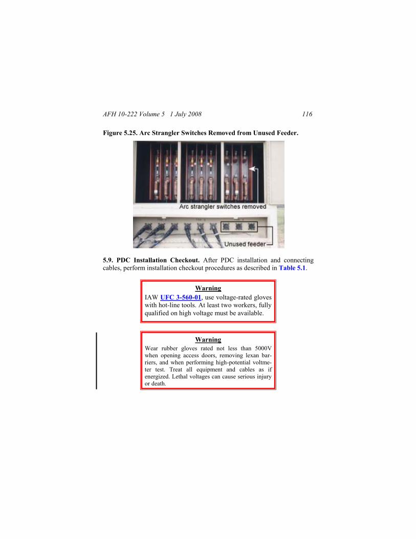
AFH 10-222 Volume 5 1 July 2008 116
Figure 5.25. Arc Strangler Switches Removed from Unused Feeder.
5.9. PDC Installation Checkout. After PDC installation and connecting
cables, perform installation checkout procedures as described in Table 5.1.
Warning
Wear rubber gloves rated not less than 5000V
when opening access doors, removing lexan bar-
riers, and when performing high-potential voltme-
ter test. Treat all equipment and cables as if
energized. Lethal voltages can cause serious injury
or death.
Warning
IAW UFC 3-560-01, use voltage-rated gloves
with hot-line tools. At least two workers, fully
qualified on high voltage must be available.

AFH 10-222 Volume 5 1 July 2008 117
Table 5.1. PDC Installation Checkout.
Installation Inspection & Pre-energizing Procedures
___ 1. Ensure that PDC has been installed, located, and oriented properly.
___ 2. Ensure that all cabling has been installed in accordance with T.O.
___ 3. Ensure equipment is accessible to personnel installing the PDC.
___ 4. Ensure accomplishment of all pre-energizing service procedures. As a
minimum, perform the following:
__ a. Check all cable terminations for tightness.
__ b. Ensure all arc-strangler switchblades have been removed and are
secured by the Electrical Supervisor or designated officer.
__ c. Install all lexan barriers, remove all loose and foreign matter, and
close fused switch assembly access doors.
__ d. Check all PDC external ground and concentric neutral connections
for mechanical and electrical security.
__ e. Ensure all personnel are clear and it is safe to energize PDC.
Energize and Preliminary Testing
___ 5. Check with generator operator(s) that power sources are available.
___ 6. Energize PDC from MEP-12/power source.
___ 7. Once all power inputs are energized and stable, wearing rubber gloves,
open fused switch assembly access doors. Then remove the lexan barrier
from the #1 output feeder circuit compartment.
___ 8. Using high-voltage phase test set, test for 4160 VAC on line side of
switchblade mounts. Test phases A, B, and C, to ground respectively.
___ 9. If no voltage at any test point, document discrepancy in equipment
records and refer to T.O. Troubleshooting Table 5-5.
___ 10. De-energize the PDC at power sources. Test all 3 phases of output feeder
circuit #1 with high-potential voltmeter to ensure unit is de-energized.
___ 11. Replace lexan barriers and close fused switch assembly doors.
Installation Verification of Operation
___ 12. Operate PDC in accordance with paragraph 4.2 of T.O. If faults occur, de-
energize immediately and refer to Chapter 5 in T.O. for troubleshooting.
5.10. Energized PDC Emergency Disconnect. If during installation or op-
eration a problem occurs and an emergency energized disconnect of an out-
put circuit is required, disconnect using the arc strangler switches—not the
load break elbows. Use the following procedures for emergency disconnect.

AFH 10-222 Volume 5 1 July 2008 118
5.10.1. Two qualified electrical personnel with safety and electrical equip-
ment must be available to disconnect (isolate) the circuit. Use rubber gloves
to open doors and remove lexan barriers. Make sure that the hole in the
arc strangler switch shaft is not exposed. If it is visible, then the circuit
must be de-energized; do not attempt an emergency disconnect.
5.10.2. Two qualified electrical personnel with switch sticks and wearing
proper Arc Flash PPE, one designated to handle Phase A and other Phase C,
position themselves at a 90-degree angle to the fuses. While holding, the far
end of the switch sticks with insulated gloves, engage the switch sticks into
the pull rings of the two outside arc strangler switches, Phases A and C (Figure 5.26).
Figure 5.26. Disconnecting Phase A and C Arc Strangler Switches.
5.10.3. On the command of ―OPEN‖ by the person pulling Phase A, both
personnel pull the switch blades open at the same time.
5.10.4. The person at Phase A immediately goes back and pulls the arc
strangler switch for Phase B (Figure 5.26a).
5.10.5. Then, one person removes all three arc strangler switches from the
mounting brackets.

AFH 10-222 Volume 5 1 July 2008 119
(Added) Figure 5.26a. Disconnecting Phase B Arc Strangler Switch.
5.10.6. If the system must be re-energized during the emergency, reverse
above procedures for installing and throwing switches. Ensure that SDC in-
dividual circuit breakers for facilities and PDPs are off prior to reconnecting
the PDC; this will prevent surging. Ensure each switchblade engages and
that at least half of the hole on the front of the switchblade shaft is covered
by the arc strangler sleeve (i.e., hole is no longer exposed).
5.11. Remote Generator Operation. For long term operation, or plant oper-
ation where several generators are in use simultaneously, control panels
(Figure 5.27) are removed from the units and installed in the control rack
(Figure 2.17) inside a centralized power plant control room, usually an ESC
or similar facility (Figure 5.28). The equipment rack can accommodate up to
four MEP-12A generator control panels.
Figure 5.27. MEP-12A Control Panel.

AFH 10-222 Volume 5 1 July 2008 120
Figure 5.28. Power Plant Control Room (ESC).
5.11.1. Six control cables, each 50 feet long (Figure 5.29), are used to con-
nect the control panel to the generator. Because two cable runs are needed
between the panel and the generator, the panel location is limited to 150 feet
from the generator.
Figure 5.29. Control Cables.
5.11.2. Cable-to-cable connections are basic cannon plugs. One end of each
of the cable lines is attached to the wiring harnesses that the control panel
was originally connected to in the generator (Figure 5.30); the other end of
each cable is attached to the top of the control panel in the equipment rack.

AFH 10-222 Volume 5 1 July 2008 121
Figure 5.30. Control Cables Connected at MEP-12A.
5.12. Connections Between Plants. At high-threat beddown locations, facil-
ity dispersal is the norm. This also applies to power plants. Two or more
plants should be established (quantity is predicated on population and size of
the installation) to ensure some degree of electrical generation capability is
retained after an attack or similar hostile act. These plants should be part of a
loop electrical distribution network to ensure some degree of electrical gen-
eration capability is retained after an attack. See paragraph 3.4.13 for more
information on interconnecting plants.
5.13. Remote Area Lighting Set (RALS). Another item designated for the
power plant area is a remote area lighting set (Figure 2.5). This set is one of
several that will usually be deployed to a contingency location but this par-
ticular set is meant to be dedicated to power plant support. It is used at a
power plant to provide overall general lighting for safety and security and
specific lighting for more critical or technical operations such as refueling.
The RALS includes a panel box/receptacle container, 13 light pole and fix-
ture assemblies, cables to connect the lights to the panel box, and cables to
connect the panel box to an SDC. The panel box/receptacle container also
serves as the storage and shipping container for the cables and lights. Al-
though the lights work using photocells, the panel box/receptacle container
should be placed within the power plant compound (perimeter fence) for
security purposes and in case manual operation is ever desired. The cable
AFH 10-222 Volume 5 1 July 2008 122
provided for connection to an SDC is only 250 feet long; therefore you‘ll
have to ensure an SDC is nearby. The same SDC should also provide service
to the power plant ESC and air conditioner. Twelve of the 13 lights are con-
nected to four 375-foot cable sections. Normally two strings of six lights are
set up, each string 750 feet long. Each string is plugged into the panel
box/receptacle container. The thirteenth light fixture is mounted on the panel
box itself. Remember, however, that the RALS does not have an internal
power source; it relies on getting power from an SDC. For emergency pur-
poses, it is wise to have one or two of the floodlight sets provided in the
BEAR package immediately available to support power plant operations.
5.14. Contingency Electrical System Installation Checklist. After the
electrical system and power plants have been installed, and before energizing
the system, use the checklist in Attachment 3 to ensure the system is ready.
5.15. DELETED.

AFH 10-222 Volume 5 1 July 2008 123
Chapter 6
Information Collection, Records, and Forms
6.1. Information Collections. No information collections are created by this
publication.
6.2. Records. The program records created as a result of the processes pre-
scribed in this publication are maintained in accordance with AFMAN 33-
363 and disposed of in accordance with the AFRIMS RDS located at
http://afrims.amc.af.mil/reds series.cfm.
6.2.1. Adopted Forms. AF IMT 847, Recommendation for Change of Publi-
cation.
6.2.2. Prescribed Forms. No prescribed forms are implemented in this publi-
cation.
KEVIN J. SULLIVAN, Lt General, USAF
DCS/Logistics, Installations & Mission Support (A4/A7)

AFH 10-222 Volume 5 1 July 2008 124
Attachment 1
GLOSSARY OF REFERENCES
AND
SUPPORTING INFORMATION
References
AFI 32-1064, Electrical Safe Practices, 25 May 2006
AFMAN 91-201, Explosive Safety Standards, 18 October 2001
AFPAM 10-219 Volume 5, Bare Base Conceptual Planning Guide,
1 June 1996
AFPAM 91-216, USAF Safety Deployment and Contingency Pamphlet,
9 Aug 2001
AF Handbook 10-222 Volume 1, Guide To Bare Base Development,
1 February 2006
AF Handbook 10-222 Volume 2, Guide To Bare Base Assets, 1 April 2006
AF Handbook 31-302, Air Base Defense Collective Skills, 1 January 1996
AFJMAN 32-1082, Facilities Engineering – Electrical Exterior Facilities,
29 November 1996
AFOSH STD 91-10, Civil Engineering, 1 July 1998
UFC 3-560-01, Electrical Safety, O&M, 7 December 2006
T.O. 00-105A-12, Installation, Operation, Maintenance Instruction and
Packaging for Reshipment with IPB – Electrical Distribution System, Bare
Base, Secondary Distribution Center, Remote Area Lighting System, Prima-
ry Cable Reel Pallet, 11 November 1994
T.O. 31-1-141, Basic Electronics Technology and Testing Practices,
28 April 2006
T.O. 35CA1-2-6-1, Operations and Maintenance Instructions with IPB –
Primary Distribution Center, 15 September 2002

AFH 10-222 Volume 5 1 July 2008 125
T.O. 35CA6-1-101, Operation, Maintenance and Overhaul Instructions with
IPB – Power Distribution Panel, 8 September 1995
T.O. 35C1-2-1-301, Operation and Maintenance Instructions with IPB,
Harvest Falcon Electrical System, 1 May 1992
T.O. 35C2-3-474-1, MEP-012A Generator Set Operator and Organizational
Maintenance Manual, 24 June 1999
T.O. 37A12-15-1, DPGDS External Fuel Supply (EFS), 30 June 2004
Abbreviations and Acronyms
ABD—Air base defense
AC—Air conditioning
ACH—Aircraft hanger
ACS—Agile combat support
AEF—Air and Space Expeditionary Force
AOR—Area of Responsibility
ATPV—Arc Thermal Performance Value
AWG—American wire gauge
BEAR—Basic Expeditionary Airfield Resources
CRPA—Cable reel pallet assembly
DOD—Department of Defense
DOT—Department of Transportation
DPGDS—Deployable Power Generation and Distribution System
ECU—Environmental control unit
EFD—Electric fusible disconnect
EFS—External fuel system
ESC—Expandable shelter container
FSTFS—Frame supported tension fabric shelters

AFH 10-222 Volume 5 1 July 2008 126
GP—General purpose
GSC—Generator set controls
HE—Harvest Eagle
HF—Harvest Falcon
HPS—High-pressure sodium
Hz—Hertz
IOP—Industrial Operations
KVA—Kilo-volt ampere
MEP—Mobile electric power
MKT—Mobile kitchen trailer
MSS—Medium shelter system
NMS—National Military Strategy
ORT—Operator‘s Remote Terminal
PDP—Power distribution panel
PS—Primary switch
PSC—Primary switch center
RALS—Remote area lighting system
SDC—Secondary distribution panel
SSS—Small shelter system
TQG—Tactical quiet generator
TO—Technical order
UTC—Unit type code

AFH 10-222 Volume 5 1 July 2008 127
Attachment 2
GENERAL INSTRUCTIONS FOR ASSEMBLING
LOAD BREAK ELBOWS
A2.1. Use these instructions in combination with the manufacturer‘s load
break elbow installation instructions. Always follow the manufacturer‘s in-
structions that come with the load break elbows if available.
A2.2. When measuring to cut cables, remember that the initial cable layout is
on the surface and will be buried as time permits. Snake the cable sufficient-
ly between equipment items along the cable route to provide enough slack to
drop the cable into the trench.
A2.3. When laying out the cable as it is coming off the cable reel pallet as-
sembly, add approximately 10 feet beyond its expected final position for
installing the load break elbow and cut the cable at this location.
A2.4. Train the cable to the final assembled position with six feet of cable
extended beyond the bushing to provide sufficient concentric neutral wire to
attach to the system ground bus (Figure A2.1). This length will also provide
sufficient cable slack for seating the elbow and moving it between parking
stands and the connection bushing.
A2.5. From the end of the cable, pull one concentric neutral wire down and
through the cable jacket at least 13 inches past the expected bushing location
(Figure A2.2). Completely strip and remove the cable jacket to this point to
provide flexibility for elbow operation (Figure A2.3).
Warning
Ensure cable is not energized before at-
tempting to assemble load break elbows.
Energized cables may be lethal.

AFH 10-222 Volume 5 1 July 2008 128
Figure A2.1. Extend Cable 6 Feet Beyond Bushing Centerline.
Figure A2.2. Strip Cable Jacket 13-inches Past Bushing Centerline.

AFH 10-222 Volume 5 1 July 2008 129
Figure A2.3. Stripping Away Cable Jacket.
A2.6. Unwind the cable‘s concentric neutral wires to this point and bend
them back along the cable and twist all but two of the concentric wires into a
grounding pigtail (do not cut these wires). Cut the two wires that were left
out of the pigtail so that there is approximately 18 inches exposed from the
cable jacket. Temporarily wrap the bent pigtail wiring using electrical tape to
prevent damage during further installation efforts (Figure A2.4).
Figure A2.4. Concentric Neutral Wires with Temporary Wrapping.

AFH 10-222 Volume 5 1 July 2008 130
A2.7. MANUFACTURER’S INSTRUCTIONS AVAILABLE. Use steps
in paragraphs A2.7.1 thru A2.7.2.3 when manufacturer’s installation
instructions are available:
A2.7.1. From the instructions, determine the required length of cable needed
for installing the load break elbow. This distance is usually 8-1/2 or 9 inches
above the point where the cable jacket was removed. Mark the cable at this
location and cut the cable squarely at this mark (Figure A2.5).
Figure A2.5. Cut Cable Squarely at Bushing Centerline.
A2.7.2. Make the cable cutbacks in accordance with the manufacturer‘s in-
stallation instruction sheet included with each kit. A brief summary follows.
A2.7.2.1. Remove the insulation shield (semiconductor) by making a cir-
cumferential cut part way through the shield. Exercise extreme caution to
avoid nicking the insulation beneath. Make several longitudinal cuts part

AFH 10-222 Volume 5 1 July 2008 131
way through the shield from the circumferential cut to the end. Again exer-
cise care not to nick the insulation. Strip the insulation shield to this length
(Figure A2.6).
Figure A2.6. Remove Shield from the Insulation.
A2.7.2.2. Lightly sand and use electrical cleaner to remove any marring of
the bare insulation (Figure A2.7).
Figure A2.7. Sand and Clean the Insulation to Remove Marring.
A2.7.2.3. From the manufacturer‘s instructions, determine the length of bare
conductor that should fit into the compression lug (usually 1-15/16 inches).
Carefully remove the insulation and conductor shield (semiconductor) from
the end of the cable (Figure A2.8). Cut squarely being careful not to nick the

AFH 10-222 Volume 5 1 July 2008 132
bare cable strands of the conductor. Apply a 1/8 inch bevel to the end of the
insulation.
Figure A2.8. Remove Insulation from Conductor.
A2.8. NO MANUFACTURER’S INSTRUCTIONS. If there are NO in-
structions or dimensions provided by the manufacturer, use the steps in
paragraphs A2.8.1 thru A2.8.5 to determine cutback deminsions:
A2.8.1. Place the neck of the load break elbow next to the cable so that the
end of the elbow is at the point where the concentric neutral wires are bent
back (normally 8-1/2 inches). Mark the cable at the center of the load break
elbow bell opening, and cut squarely at the mark (Figure A2.9).
Figure A2.9. Measure Distance to Cut Cable with Elbow.

AFH 10-222 Volume 5 1 July 2008 133
A2.8.2. Push a piece of scrap wire into the opening at the base of the com-
pression lug until it bottoms out to measure the inside length of the lug, this
will be referred to as ―B‖ (Figure A2.10). Note: The compression lug may
also be called various terms by the manufacturer, such as the connector bar-
rel, contact bushing, or connector bushing.
Figure A2.10. Measuring Inside Length of Compression Lug.
A2.8.3. Using Figure A2.11 as a guide, place the compression lug next to
the bell opening of the load break elbow such that the lug‘s eye aligns with
the center of the load break elbow‘s bell opening (line A). Place the cut end
of the cable next to the lug‘s maximum depth and mark the cable at the base
of the load break elbow where the neck just begins (line C).
A2.8.4. From the end of the cable, measure to point ―B‖ and add one eighth
of an inch. At this point, remove the insulation shield, insulation, and con-
ductor shield to expose the bare conductor; try not to nick the conductor
(Figure A2.12). Clean the exposed conductor using a wire brush.
A2.9. Immediately place the compression lug containing inhibitor grease on
the conductor and twist and align to spread the inhibitor coating inside the
contact bushing. Check to ensure there is a 1/8 inch gap between the lug bot-
tom and the insulation. This space is needed for expansion of the lug when it
is crimped and to prevent damage to the insulation. Make sure the threaded
hole in the lug faces the bushing. If not properly trained, the cables may

AFH 10-222 Volume 5 1 July 2008 134
have too much slack requiring the elbows to be twisted 45-90 degrees to
make the connection. This misalignment will likely create tension on the lug
and, through vibration, may produce a loose connection leading to fires or
unscheduled outages.
Figure A2.11. Guide for Determining Shield Removal.
Figure A2.12. Insulation and Conductor Shield Removed.
A2.10. It is a good idea to hand tighten the probe into the threads of the
compression lug prior to crimping. This will prevent distortion of the com-
pression lug‘s eye and to ensure proper thread engagement. Place as many

AFH 10-222 Volume 5 1 July 2008 135
crimps on the compression lug barrel as will fit without overlapping using a
tool and die combination (Figure A2.13). After crimping, remove the probe
and smooth any sharp edges or ears caused by the crimping process. Clean
the excess inhibitor grease from the lug by wiping toward the threaded eye
with a lint free cloth saturated with safety solvent (inhibitor residue can re-
sult in insulation damage and ultimate terminator failure). Note: Crimping
tools and their instructions vary; follow the manufacturer‘s instructions.
Figure A2.13. Crimping Compression Lug.
A2.11. Remove the insulation shield to the mark at ―C,‖ as determined earli-
er. Take care that you do not nick or gouge the insulation. Cut a one-eighth
inch bevel on the insulation to ease the installation of the elbow (Figure A2-
14). Do not bend the cable along the unprotected length where the insulation
is exposed. Protect the insulation from damage while exposed.
A2.12. Clean the exposed insulation surface with aluminum oxide abrasive
cloth (Garnet Cloth) to remove all traces of semi conducting shielding and
other foreign matter; do not use emery cloth which contains conductive grit
(Figure A2.15). Then wipe all exposed insulation surfaces with a lint free
cloth saturated with safety solvent. Wipe towards the black semiconductor
material without touching it. Be careful not to drag the black semiconductor

AFH 10-222 Volume 5 1 July 2008 136
material onto the clean insulation. In addition, clean the inside of the elbow
housing, the cable entrance, and the loadbreak bushing.
Figure A2-14. Insulation Shield Removed.
Figure A2.15. Cleaning Insulation with Abrasive Cloth.
A2.13. When the solvent is completely dry, apply a thin coat of silicone
grease, supplied with the elbow kit, to the exposed cable insulation, elbow
housing, elbow cable entrance, and loadbreak bushing. With a twisting mo-
tion, push the elbow onto the cable until the threaded eye of the compression
lug is visible through the elbow bell housing (Figure A4.16). Use a clean
dry rag to remove all excess silicon grease from the neck area of the load
break elbow.

AFH 10-222 Volume 5 1 July 2008 137
Figure A4.16. Pushing Elbow onto Cable and Aligning Lug’s Eye.
A2.14. Insert the threaded end of the loadbreak probe into the elbow housing
being careful not to contaminate the probe with silicone grease. By hand,
thread the loadbreak probe into the threaded eye of the compression lug
(Figure A2.17). Be careful not to cross thread the connector and probe, as
cross-threading causes loose connections. Tighten the loadbreak probe with
the torque applicator tool supplied with the elbow kit. Proper torque is ap-
plied when the torque applicator bends 180 degrees from its original shape
(do not reuse the torque applicator).
A2.15. To seal the cable and load break elbow from extraneous debris and
moisture, use electrician‘s tape to wrap the end of the load break elbow and
exposed insulation shield (Figure A2.18) from the area at the load break
elbow‘s base to the exposed concentric neutral wires.

AFH 10-222 Volume 5 1 July 2008 138
Figure A2.17. Tightening Probe with Torque Applicator.
Figure A2.18. Wrap the End of the Elbow for Protection.
A2.16. Depending on manufacturer of the load break elbow, feed one or two
strands of concentric neutral wire through grounding eye(s) of the load break
elbow (Figure A2.19). Twist and secure, and then cut off any excess wire.

AFH 10-222 Volume 5 1 July 2008 139
Take care not to damage the grounding eye(s) on the elbow when connecting
the concentric neutral wires.
Figure A2.19. Ground Wires Connected to Grounding Eyes.
A2.17. Lubricate the bushing, elbow bell, and arc follower portion of the
probe assembly with lubricant supplied prior to seating on a bushing.
A2.18. Prior to energizing the circuit, install the load break elbow on the
parking bushing. Fasten the ground wire to the grounding lug or bus plate.
Move the load break elbow between the parked bushing and the soon to be
active bushing to determine if the pigtailed ground connection is of the cor-
rect length.
A2.19. If the pigtail length is adequate, finish wrapping around the base of
the bent wires and the cable as shown in Figures A2.18 and A2.19. In addi-
tion to sealing the outside jacket of the cable, this will provide stress relief
for the bent portion of the concentric neutral wires. If the pigtail ground is
too short, unwind additional length of concentric neutral wires until the pig-
tail length is adequate. Then, finish wrapping electrician‘s tape around the
base of the bent wires and up the insulation shield to the base of the elbow.

AFH 10-222 Volume 5 1 July 2008 140
Note: In most situations, approximately 3 feet of jacket below the elbow can
be removed. The jacket must be retained on all primary cable in contact with
soil and for a minimum of 1 foot above finished grade.

AFH 10-222 Volume 5 1 July 2008 141
Attachment 3
CONTINGENCY ELECTRICAL POWER SYSTEM
INSTALLATION CHECKLIST
__ 1. Has a holding area for temporary storage of incoming electrical system components been established?
__ 2. Have mission essential facilities been identified and coordinated with the appropriate command?
__ 3. Have the locations of mission essential facilities been identified?
__ 4. Has a requirement for sustained operations at the contingency loca-tion been confirmed?
__ 5. Has an initial estimate of the electrical loads of mission essential facilities been made to aid in sizing generators to the requirements?
__ 6. Has vehicle/equipment support for moving electrical equipment to site locations been arranged?
__ 7. Do all electrical installation crews have an individual capable of operating materials handling equipment?
__ 8. Have SDCs been placed at locations where emergency/back-up ge-nerators can serve multiple mission essential facilities?
__ 9. Have emergency/back-up generators been connected to mission es-sential facilities?
__ 10. Have light carts been operationally checked and allocated to criti-cal flightline functional areas?
__ 11. Have personnel been identified to perform routine maintenance and refueling operations on emergency/back-up generators?
__ 12. Have electrical feeder schedules been developed based on the layout of the various base facility groups?
__ 13. Have SDC circuits been sized to handle future air conditioning loads (if applicable)?
__ 14. Has a plan showing the layout of the electrical distribution system been developed?
__ 15. Have locations for power plants been determined?
__ 16. Have prime generators been positioned at power plant locations?

AFH 10-222 Volume 5 1 July 2008 142
__ 17. Have fuel bladders been installed at power plant locations?
__ 18. Have fuel bladders been properly bermed?
__ 19. Have control panels been correctly connected to prime generators?
__ 20. Have PSCs/PDCs been placed and connected at power plants?
__ 21. Have adequate grounding systems been installed at power plants?
__ 22. Have SDCs been allocated to and placed in the various facility groups in such a way that portions of the groups can be brought on line as facilities are erected?
__ 23. Have SDCs been placed in areas accessible to vehicles, yet not adjacent to heavy traffic or personnel flow?
__ 24. Have SDCs been grounded?
__ 25. Have the cables connecting facilities, panel boxes, SDCs, PSCs/PDCs initially been installed along the surface of the ground?
__ 26. Have cables that cross roadways been adequately protected from damage by vehicle traffic?
__ 27. Have facilities been brought onto the base electrical grid as soon as reasonably possible once electrical connections have been completed?
__ 28. Have emergency/back-up generators serving mission essential fa-cilities been placed in backup power mode once power plant electrical service was available?
__ 29. Have personnel been specifically designated to provide around-the-clock power plant operation?
__ 30. Have RALS units been installed at locations requiring large-scale area lighting?
__ 31. If sustained operations are planned and electrical system is fully functional in an above ground mode, have efforts been started to bury electrical cables?
__ 32. Have accurate records/drawings been made of buried electrical cables?
__ 33. Have power plant operators been informed of what plant operation records to maintain?
__ 34. Have arrangements been made for power plant refueling?