air force handbook 10-222, volume 10 1 may 2000 … · 2 afh 10-222 volume 10 1 may 2000 air force...
TRANSCRIPT

2 AFH 10-222 Volume 10 1 May 2000
AIR FORCE HANDBOOK 10-222, Volume 10 1 MAY 2000
GUIDE TO HARVEST FALCON ELECTRICAL
SYSTEM INSTALLATION
DEPARTMENT OF THE AIR FORCE
Report Documentation Page Form ApprovedOMB No. 0704-0188
Public reporting burden for the collection of information is estimated to average 1 hour per response, including the time for reviewing instructions, searching existing data sources, gathering andmaintaining the data needed, and completing and reviewing the collection of information. Send comments regarding this burden estimate or any other aspect of this collection of information,including suggestions for reducing this burden, to Washington Headquarters Services, Directorate for Information Operations and Reports, 1215 Jefferson Davis Highway, Suite 1204, ArlingtonVA 22202-4302. Respondents should be aware that notwithstanding any other provision of law, no person shall be subject to a penalty for failing to comply with a collection of information if itdoes not display a currently valid OMB control number.
1. REPORT DATE 01 MAY 2000
2. REPORT TYPE N/A
3. DATES COVERED -
4. TITLE AND SUBTITLE Guide To Harvest Falcon Electrical System Installation - Air ForceHandbook 10-222, VOLUME 10
5a. CONTRACT NUMBER
5b. GRANT NUMBER
5c. PROGRAM ELEMENT NUMBER
6. AUTHOR(S) 5d. PROJECT NUMBER
5e. TASK NUMBER
5f. WORK UNIT NUMBER
7. PERFORMING ORGANIZATION NAME(S) AND ADDRESS(ES) Secretary Of The Air Force Washington, DC
8. PERFORMING ORGANIZATIONREPORT NUMBER
9. SPONSORING/MONITORING AGENCY NAME(S) AND ADDRESS(ES) 10. SPONSOR/MONITOR’S ACRONYM(S)
11. SPONSOR/MONITOR’S REPORT NUMBER(S)
12. DISTRIBUTION/AVAILABILITY STATEMENT Approved for public release, distribution unlimited
13. SUPPLEMENTARY NOTES
14. ABSTRACT
15. SUBJECT TERMS
16. SECURITY CLASSIFICATION OF: 17. LIMITATION OF ABSTRACT
UU
18. NUMBEROF PAGES
118
19a. NAME OFRESPONSIBLE PERSON
a. REPORT unclassified
b. ABSTRACT unclassified
c. THIS PAGE unclassified
Standard Form 298 (Rev. 8-98) Prescribed by ANSI Std Z39-18

BY ORDER OF THE AIR FORCE HANDBOOK 10-222, VOLUME 10 SECRETARY OF THE AIR FORCE 1 MAY 2000
Operations
GUIDE TO HARVEST FALCON ELECTRICAL SYSTEM INSTALLATION
NOTICE: This publication is available digitally on the SAF/AFDPO WWW site at: http://afpubs.hq.af.mil. OPR: HQ AFCESA/CEXR (Major Gregory A. Cummings) Certified by: HQ AFCESA/CEX (Colonel Bruce F. Mc Connell) Pages: 117/Distribution: F and X This handbook addresses the actions necessary to install the Harvest Falcon Electrical Distribution System (HF EDS) to support a bare base force deployment. The basics of the system installation may also be used for installation of the system to support peacetime contingencies. The users of this handbook are primarily electrical and power production personnel charged with providing electrical system support for bare base beddowns. Readiness and deployment planners and base level mobility team chiefs responsible for bare base planning should also use it for information regarding siting issues and requirements. The electrical and power production personnel using this handbook are assumed to have a basic knowledge of electrical components of the system. At least one 3E051 and 3E052 specialist should be task qualified for directing and meeting the operation and maintenance requirements for the appropriate components and the system. Other users of this handbook are assumed to be familiar with the basic Harvest Falcon system. The guidance in this handbook is based on information found in: technical orders (TOs) 35C1-2-1-301, 35C2-3-474-1, 35CA1-2-6-1, 35CA2-10-1, 35CA6-1-101, 37A12-15-1, and 00-105A-12; AF Qualification Training Package 3E0X1-26.2.2.6; the Silver Flag Exercise

2 AFH 10-222 Volume 10 1 May 2000
Site courses for Bare Base Electrical Distribution Systems and ElectricalSystems Specialists; AFPAM 10-219 Volume 5; AF Handbooks 10-222 Volume 1, 2, and 5; and AF Handbook 31-302. This guidance augments the applicable TOs. INTRODUCTION .....................................................................................................5 MAJOR SYSTEM COMPONENTS ......................................................................8 SITE PLANNING AND LA YOUT ......................................................................24 INSTALLATION.....................................................................................................63 Figures 1. Bare Base Set-up Near Flightline ....................................................................5 2. MEP-12A Generator..........................................................................................9 3. MEP-005 Generator.........................................................................................10 4. MEP-006 Generator.........................................................................................11 5. MEP-007 Generator.........................................................................................12 6. Primary Distribution Center ...........................................................................13 7. Load Break Elbow (on Grip-All Clamp Stick) ..........................................13 8. Cable Skid with Three Reels of Primary Cable ..........................................14 9. Secondary Distribution Center.......................................................................15 10. SDC with MEP Cable ......................................................................................16 11. Cannon Plug Connections on Low Voltage Cable .....................................17 12. Typical Power Distribution Panels ................................................................18 13. Equipment Rack with Generator Control Panels ........................................20 14. Typical (22x22) Fuel Bladder ........................................................................21 15. Fuel Manifold ....................................................................................................21 16. Basic Electrical Distribution System Schematic .........................................23 17. Dispersal Patterns for 3-, 6-, 9-, and 12-Facilitiy Groupings....................25 18. Dispersal Patterns for 24-Facility Grouping ................................................26 19. Typical Two SDCs Required to Provide Power to Non-Dispersed 24-
Facility Grouping..............................................................................................26 20. Two SDCs Unable to Cover a Dispersed 24-Facility Grouping ..............27

AFH 10-222 Volume 10 1 May 2000 3
21. SDCs Required to Provide High Quality Power to Dispersed 24-Facility Grouping ............................................................................................................27
22. Linear Base Layout..........................................................................................33 23. Radial Electrical Distribution System for 1,100-Person Power Plant(s)34 24. Conventional Type Base Layout....................................................................35 25. Interconnected Electrical Distribution System for 1,100-Person Power
Plant(s)................................................................................................................35 26. Critical Facility SDCs Connected by Parked Cables .................................36 27. Typical Plant Layout Groupings....................................................................37 28. Typical Utility Corridor for Non-Dispersed TEMPER Tents...................42 29. Typical 1,100-Person Layout with Major Roadway Grid .........................43 30. Utility Corridor with All Support Equipment..............................................44 31. Typical Growth from 1,100- to 3,300-Person Layout................................45 32. Example SDC Circuit for Wing Operations Group....................................57 33. Typical Connection between Two PDCs ....................................................60 34. Typical Parked Cables between Two SDCs on Different Circuits ..........61 35. Rerouting of Cables to Prevent Overloading of Remaining PDC............62 36. PDC Site Requirements...................................................................................64 37. Typical PDC Clearances .................................................................................65 38. Placement of PDC Near Generators ..............................................................65 39. Ground Stud on MEP-12A Generator...........................................................67 40. Grounding Locations on the PDC..................................................................68 41. Grounding Location on the SDC ...................................................................69 42. Typical Equipment Horizontal Ground Rod Installation...........................70 43. Typical Equipment Laced Wire Ground Installation .................................70 44. Typical Equipment Grounding Grid Platform Installation........................71 45. Tractor with Backhoe, Blade, and Trenching Wheel ................................74 46. Trench and Cable Detail..................................................................................75 47. Multiple Cable Runs in Common Trench ...................................................76 48. Primary Cable PDC Line Side Connection..................................................78 49. PDC Output Ground Connection...................................................................79 50. SDC Input Ground Connection......................................................................80 51. Remove the Center Pole of SDC Fusible Disconnect Switches...............81 52. Connect Cables to SDC Input Bushings.......................................................82 53. PDC Load Side Feeder Connection...............................................................83

AFH 10-222 Volume 10 1 May 2000 4
54. Arc Strangler Switches Removed from Unused PDC Feeders.................83 55. Input and Output Cables on a SDC ...............................................................84 56. Cannon Plug Connection from SDC to Small Shelter System PDP ........85 57. Cannon Plug Connection from SDC to ESC Service Panel......................85 58. Cannon Plug Connection from PDP to ECU ..............................................86 59. Use of Grip-All Clamp Stick for Connecting to Generator.......................87 60. Proper Set-up for Disconnecting the Arc Strangler Switches...................89 61. Detail of Electric Fusible Disconnect (EFD) ...............................................91 62. EFD Center Pole Disconnect with a Switch Stick......................................91 63. Branch Connected SDCs with a MEP -12A Generator .............................92 Tables 1. 1,100-Person Bare Base Facility List............................................................38 2. 3,300- Person Bare Base Facility List...........................................................39 3. General Separation Distances for Facilities in Groups..............................41 4. Typical Harvest Falcon Demand Factors .....................................................46 5. Typical Harvest Falcon Electrical Planning Factors ..................................48 6. Example Secondary Distribution Schedule for a Wing Operations Group ..................................................................................................................53 7. Example SDC Feeder Schedule for a Wing Operations Group................55 Attachments 1. Additional Individual Facility Cable .............................................................94 2. Typical Layout Requirements for Power Plants .........................................96 3. Specific Facility Matrix ................................................................................100 4. General Instructions for Assembling Load Break Elbows ......................103

AFH 10-222 Volume 10 1 May 2000 5
INTRODUCTION BACKGROUND ON HARVEST FALCON A Harvest Falcon deployment package is an air transportable system consisting of: tents or small shelter systems (SSS); medium-type shelters that could include frame supported tension fabric shelters (FSTFS), Dome shelters, or medium shelter systems (MSS); hardwall shelters; expandable shelter containers (ESC); equipment; and utility systems and components. It is designed for worldwide deployment to support personnel and aircraft under bare base conditions (figure 1). Figure 1. Bare Base Set-up near Flightline.
It provides both mission and housekeeping support for up to 55,000 personnel at up to 15 separate beddown locations. The building blocks for a deployment package are the 1,100-person bare base housekeeping set, the initial flightline set, and the industrial operations set. These basic building blocks are used to support one squadron of aircraft or a composite of aircraft in one unit. Each additional aircraft squadron/composite unit is supported by

AFH 10-222 Volume 10 1 May 2000 6
an additional housekeeping set and a follow-on flightline set. Specialized subsets of equipment are available either separately or within the set packages for such items as remote kitchens, avionics support shops, air munitions packages, and medical facilities. The basic Harvest Falcon deployment sets include:
Housekeeping Set (Unit Type Code (UTC) XFBKA): Tents or SSS, hardwall shelters, mission essential generators, basic electrical and water utilities, latrines and showers, environmental control units, area lighting systems, and other basic equipment to provide billeting, administrative, command, messing, hygiene, and laundry facilities to support a 1,100-person deployment. Industrial Operations Set (UTC XFBRB): Tents, hardwall shelters, medium-type shelters, ESCs, and additional utility equipment and shop facilities for CE, Services, Transportation, and Supply organizations and other base support/command/ administrative functions. Initial Flightline Support Set (UTC XFBS1): Emergency airfield lighting, aircraft arresting systems, aircraft hangars, tents, hardwall shelters, medium-type shelters, ESCs, revetments, field latrines, additional electrical distribution equipment, and other facilities/equipment to support aircraft operation and generation, flightline shops and support functions, and other direct mission support functions. The initial package supports the first aircraft-operating squadron or composite unit. Follow-on Flightline Operations Set (UTC XFBS2): Additional hardwall shelters, an aircraft hangar, ESCs, field latrines and other facilities/equipment for each follow-on aircraft squadron or composite unit.
The HF EDS is a critical component for the bed down of the Harvest Falcon system.

AFH 10-222 Volume 10 1 May 2000 7
Note: The actual contents of each UTC may have been adjusted based on equipment availability, upgrades, and/or substitutions and deployment and mission requirements. Detailed UTCs should be reviewed and mission planners, users, and logisticians need to work together to ensure deploying units know what assets will actually be deployed.
AFH 10-222 Volume 10 1 May 2000 8
MAJOR SYSTEM COMPONENTS
Following are the major electrical system components included within the HF EDS. Generators
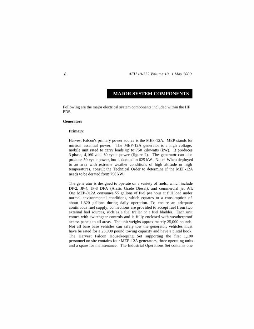
Primary: Harvest Falcon's primary power source is the MEP-12A. MEP stands for mission essential power. The MEP-12A generator is a high voltage, mobile unit rated to carry loads up to 750 kilowatts (kW). It produces 3-phase, 4,160-volt, 60-cycle power (figure 2). The generator can also produce 50-cycle power, but is derated to 625 kW. Note: When deployed to an area with extreme weather conditions of high altitude or high temperatures, consult the Technical Order to determine if the MEP-12A needs to be derated from 750 kW. The generator is designed to operate on a variety of fuels , which include DF-2, JP-4, JP-8 DFA (Arctic Grade Diesel), and commercial jet A-1. One MEP-012A consumes 55 gallons of fuel per hour at full load under normal environmental conditions, which equates to a consumption of about 1,320 gallons during daily operation. To ensure an adequate continuous fuel supply, connections are provided to accept fuel from two external fuel sources, such as a fuel trailer or a fuel bladder. Each unit comes with switchgear controls and is fully enclosed with weatherproof access panels to all areas. The unit weighs approximately 25,000 pounds. Not all bare base vehicles can safely tow the generator; vehicles must have be rated for a 25,000 pound towing capacity and have a pintal hook. The Harvest Falcon Housekeeping Set supporting the first 1,100 personnel on site contains four MEP-12A generators, three operating units and a spare for maintenance. The Industrial Operations Set contains one
AFH 10-222 Volume 10 1 May 2000 9
additional unit. For each 1,100-person increment added to the base population, three additional operating generators and a maintenance spare generator are required. One MEP-12A completely loads a C-130 cargo aircraft.
Figure 2. MEP-12A Generator.
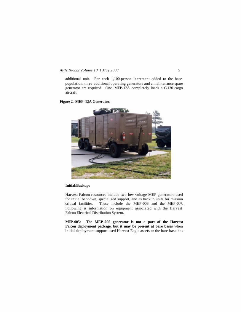
Initial/Backup: Harvest Falcon resources include two low voltage MEP generators used for initial beddown, specialized support, and as backup units for mission critical facilities. These include the MEP-006 and the MEP-007. Following is information on equipment associated with the Harvest Falcon Electrical Distribution System. MEP-005: The MEP-005 generator is not a part of the Harvest Falcon deployment package, but it may be present at bare bases when initial deployment support used Harvest Eagle assets or the bare base has
AFH 10-222 Volume 10 1 May 2000 10
since received a Harvest Eagle package for support of non-flying units. The generator (figure 3) is a diesel powered, mobile unit that provides 3-phase, 60 cycle, 120/208-volt power to support loads up to 30kW. This generator may also be operated at 50 cycles and is derated to 24 kW.
Figure 3. MEP-005 Generator.
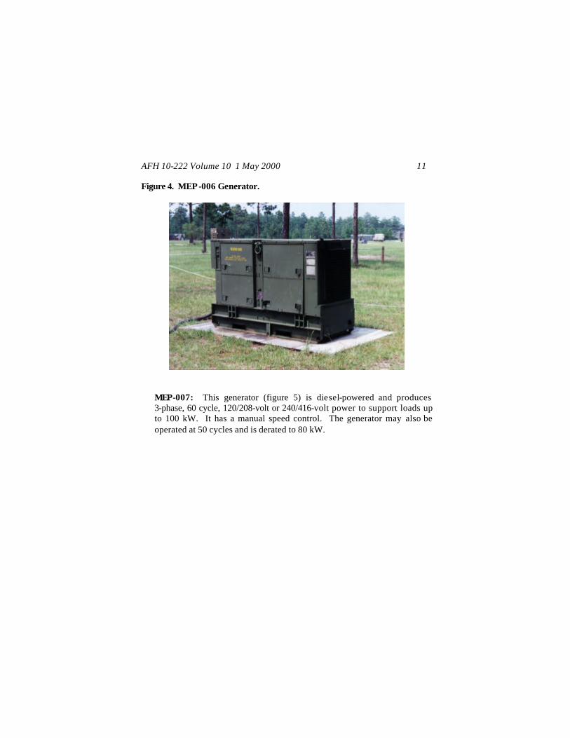
MEP-006: This generator (figure 4) is diesel powered and produces 3-phase, 60 cycle, 120/208-volt power to support loads up to 60 kW. The generator may also be operated at 50 cycles and is derated to 48 kW.
AFH 10-222 Volume 10 1 May 2000 11
Figure 4. MEP-006 Generator.
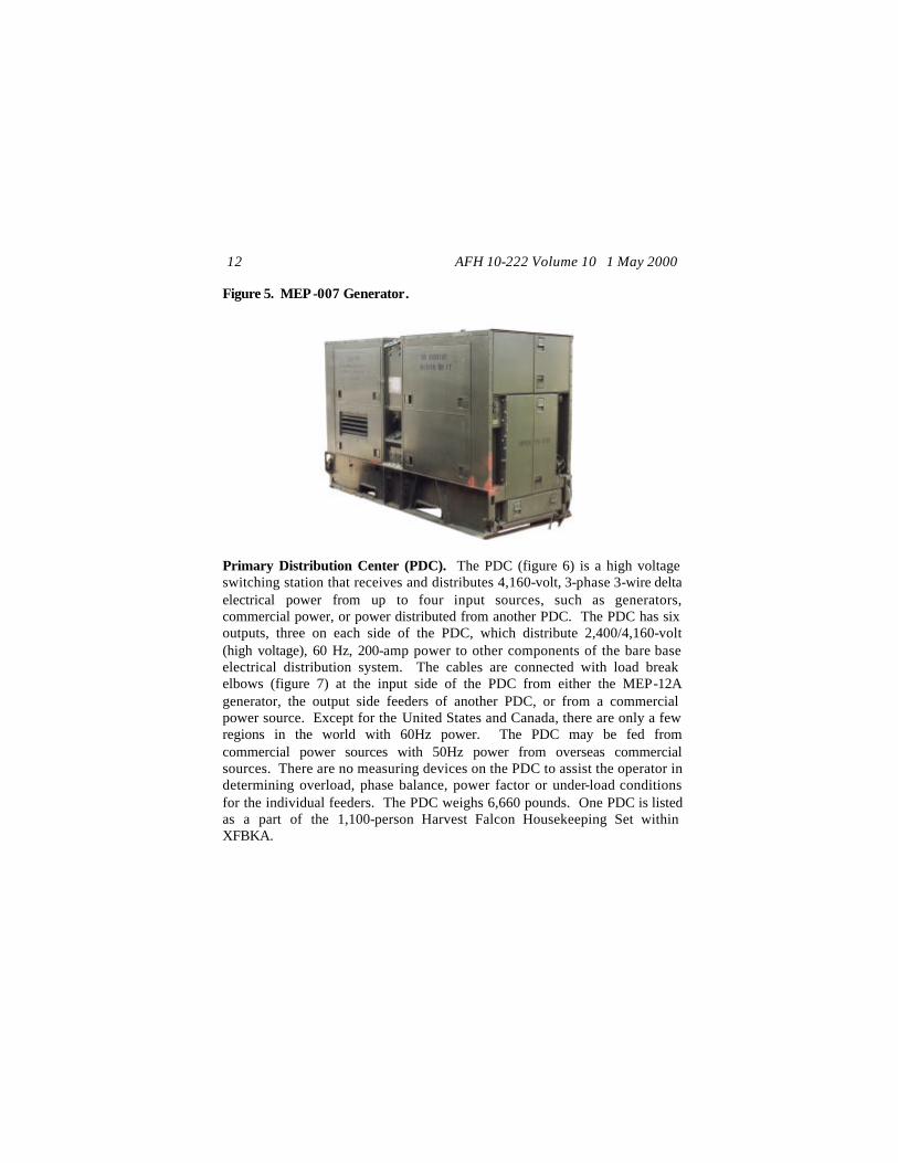
MEP-007: This generator (figure 5) is diesel-powered and produces 3-phase, 60 cycle, 120/208-volt or 240/416-volt power to support loads up to 100 kW. It has a manual speed control. The generator may also be operated at 50 cycles and is derated to 80 kW.
AFH 10-222 Volume 10 1 May 2000 12
Figure 5. MEP-007 Generator.
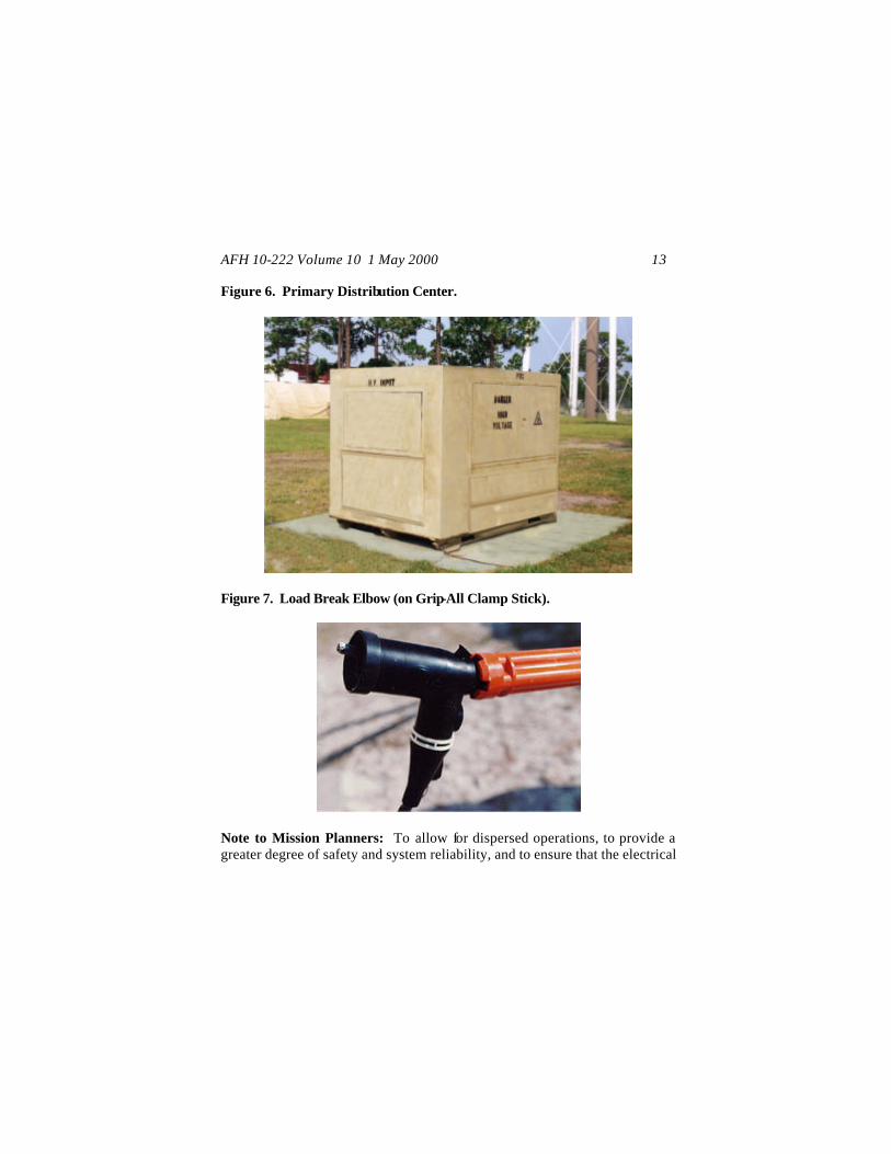
Primary Distribution Center (PDC). The PDC (figure 6) is a high voltage switching station that receives and distributes 4,160-volt, 3-phase 3-wire delta electrical power from up to four input sources, such as generators, commercial power, or power distributed from another PDC. The PDC has six outputs, three on each side of the PDC, which distribute 2,400/4,160-volt (high voltage), 60 Hz, 200-amp power to other components of the bare base electrical distribution system. The cables are connected with load break elbows (figure 7) at the input side of the PDC from either the MEP-12A generator, the output side feeders of another PDC, or from a commercial power source. Except for the United States and Canada, there are only a few regions in the world with 60Hz power. The PDC may be fed from commercial power sources with 50Hz power from overseas commercial sources. There are no measuring devices on the PDC to assist the operator in determining overload, phase balance, power factor or under-load conditions for the individual feeders. The PDC weighs 6,660 pounds. One PDC is listed as a part of the 1,100-person Harvest Falcon Housekeeping Set within XFBKA.
AFH 10-222 Volume 10 1 May 2000 13
Figure 6. Primary Distribution Center.
Figure 7. Load Break Elbow (on Grip-All Clamp Stick).
Note to Mission Planners: To allow for dispersed operations, to provide a greater degree of safety and system reliability, and to ensure that the electrical
AFH 10-222 Volume 10 1 May 2000 14
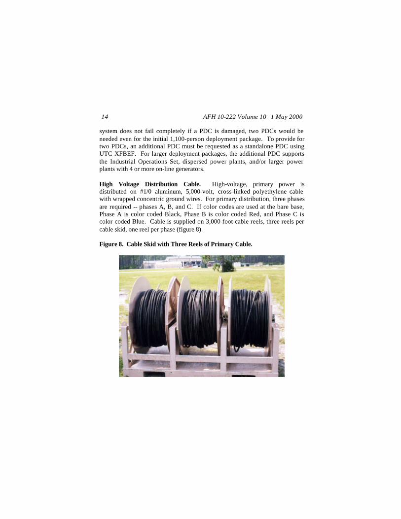
system does not fail completely if a PDC is damaged, two PDCs would be needed even for the initial 1,100-person deployment package. To provide for two PDCs, an additional PDC must be requested as a standalone PDC using UTC XFBEF. For larger deployment packages, the additional PDC supports the Industrial Operations Set, dispersed power plants, and/or larger power plants with 4 or more on-line generators. High Voltage Distribution Cable. High-voltage, primary power is distributed on #1/0 aluminum, 5,000-volt, cross-linked polyethylene cable with wrapped concentric ground wires. For primary distribution, three phases are required -- phases A, B, and C. If color codes are used at the bare base, Phase A is color coded Black, Phase B is color coded Red, and Phase C is color coded Blue. Cable is supplied on 3,000-foot cable reels, three reels per cable skid, one reel per phase (figure 8). Figure 8. Cable Skid with Three Reels of Primary Cable.
AFH 10-222 Volume 10 1 May 2000 15
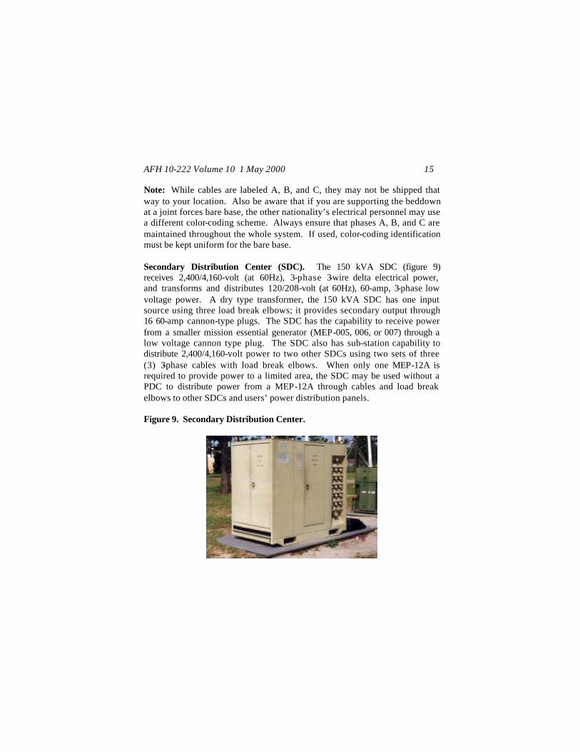
Note: While cables are labeled A, B, and C, they may not be shipped that way to your location. Also be aware that if you are supporting the beddown at a joint forces bare base, the other nationality’s electrical personnel may use a different color-coding scheme. Always ensure that phases A, B, and C are maintained throughout the whole system. If used, color-coding identification must be kept uniform for the bare base. Secondary Distribution Center (SDC). The 150 kVA SDC (figure 9) receives 2,400/4,160-volt (at 60Hz), 3-phase 3-wire delta electrical power, and transforms and distributes 120/208-volt (at 60Hz), 60-amp, 3-phase low voltage power. A dry type transformer, the 150 kVA SDC has one input source using three load break elbows; it provides secondary output through 16 60-amp cannon-type plugs. The SDC has the capability to receive power from a smaller mission essential generator (MEP-005, 006, or 007) through a low voltage cannon type plug. The SDC also has sub-station capability to distribute 2,400/4,160-volt power to two other SDCs using two sets of three (3) 3-phase cables with load break elbows. When only one MEP-12A is required to provide power to a limited area, the SDC may be used without a PDC to distribute power from a MEP-12A through cables and load break elbows to other SDCs and users’ power distribution panels. Figure 9. Secondary Distribution Center.
AFH 10-222 Volume 10 1 May 2000 16
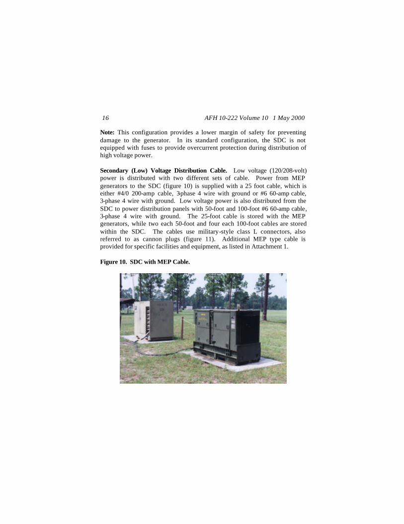
Note: This configuration provides a lower margin of safety for preventing damage to the generator. In its standard configuration, the SDC is not equipped with fuses to provide overcurrent protection during distribution of high voltage power. Secondary (Low) Voltage Distribution Cable. Low voltage (120/208-volt) power is distributed with two different sets of cable. Power from MEP generators to the SDC (figure 10) is supplied with a 25 foot cable, which is either #4/0 200-amp cable, 3-phase 4 wire with ground or #6 60-amp cable, 3-phase 4 wire with ground. Low voltage power is also distributed from the SDC to power distribution panels with 50-foot and 100-foot #6 60-amp cable, 3-phase 4 wire with ground. The 25-foot cable is stored with the MEP generators, while two each 50-foot and four each 100-foot cables are stored within the SDC. The cables use military-style class L connectors, also referred to as cannon plugs (figure 11). Additional MEP type cable is provided for specific facilities and equipment, as listed in Attachment 1. Figure 10. SDC with MEP Cable.

AFH 10-222 Volume 10 1 May 2000 17
Figure 11. Cannon Plug Connections on Low Voltage Cable.
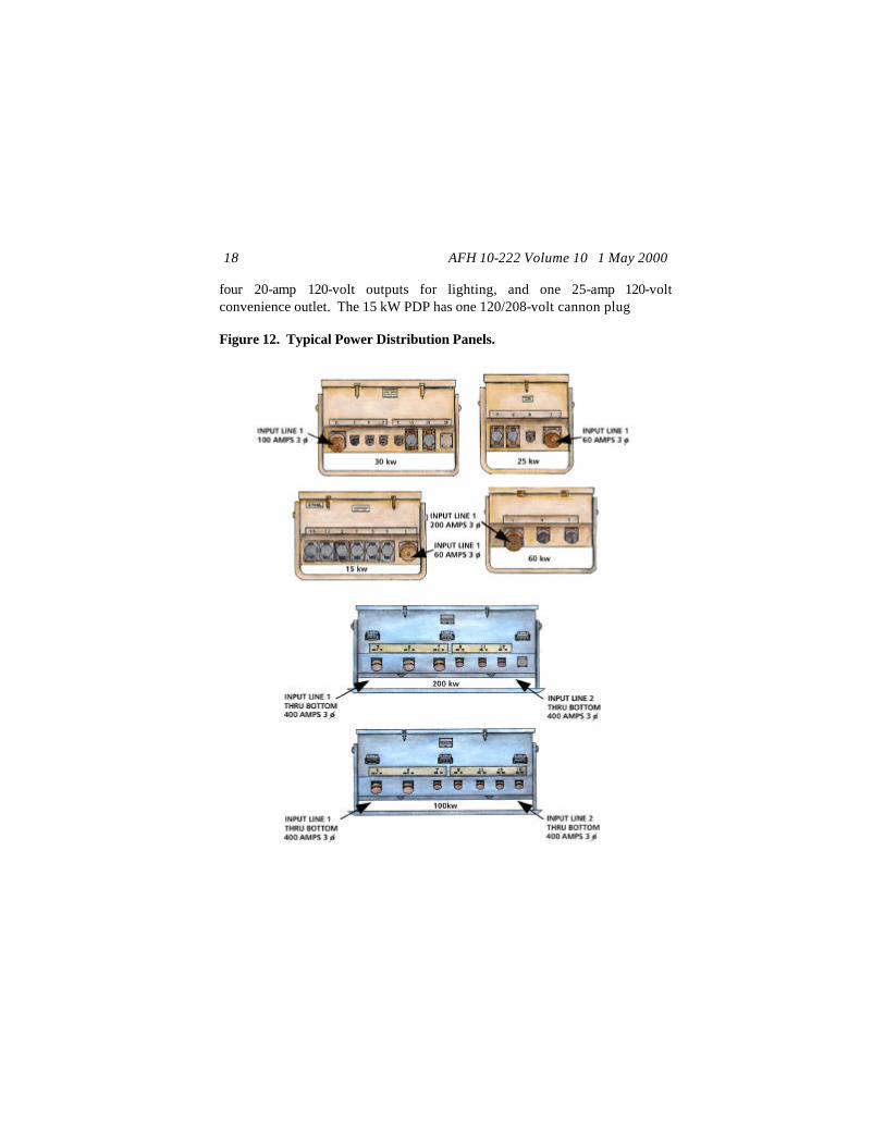
Power Distribution Panel (PDP). The PDP is a circuit breaker panel. PDPs come in several sizes and functions: 15 kW, 25 kW, 30 kW, 60 kW, 100 kW, and 200 kW (figure 12). The larger PDPs (i.e., 60 kW, 100 kW, and 200 kW) can provide service as sub-distribution centers to other PDPs and major loads. Smaller PDPs usually serve a single facility and come with the facility being served. In lieu of a PDP, some facilities such as aircraft hangars, large and medium frame-supported tensioned fabric structures, Dome shelters, hardwall General Purpose (GP) shelters, and Expandable Shelter Containers (ESCs) have power distribution centers that are a part of the facility. The PDP receives 120/208-volt power from the SDC and divides it into separate circuits to run a given facility’s HVAC, lighting, and utility outlet systems. The 15 kW and the 25 kW PDPs normally act to support a single facility and its associated environmental control unit. The 25 kW PDP is associated with the TEMPER tent. It has one 120/208-volt cannon plug input, one 120/208-volt cannon plug output (usually for an environmental control unit),
AFH 10-222 Volume 10 1 May 2000 18
four 20-amp 120-volt outputs for lighting, and one 25-amp 120-volt convenience outlet. The 15 kW PDP has one 120/208-volt cannon plug Figure 12. Typical Power Distribution Panels.

AFH 10-222 Volume 10 1 May 2000 19
input, one 120/208-volt cannon plug output for an environmental control unit, and twelve 20-amp 120-volt outputs for lighting/convenience outlets. The 15, 25, and 30 kW PDPs have smaller cannon plug connections. The 60, 100, and 200 kW PDPs should have 200 amp connection plugs, but check on the type of connection required for the specific PDP and use the TO. Some of the PDP models may have to be hard wired through the bottom of the PDP panel, or they may have the larger 200 amp cannon plug connection. Additional Associated Equipment The following are also associated with the generation, installation, or operation of the HF EDS. Power Plant System: This system (UTC UFBEX), which is included in the housekeeping set, has the additional components for a power plant.
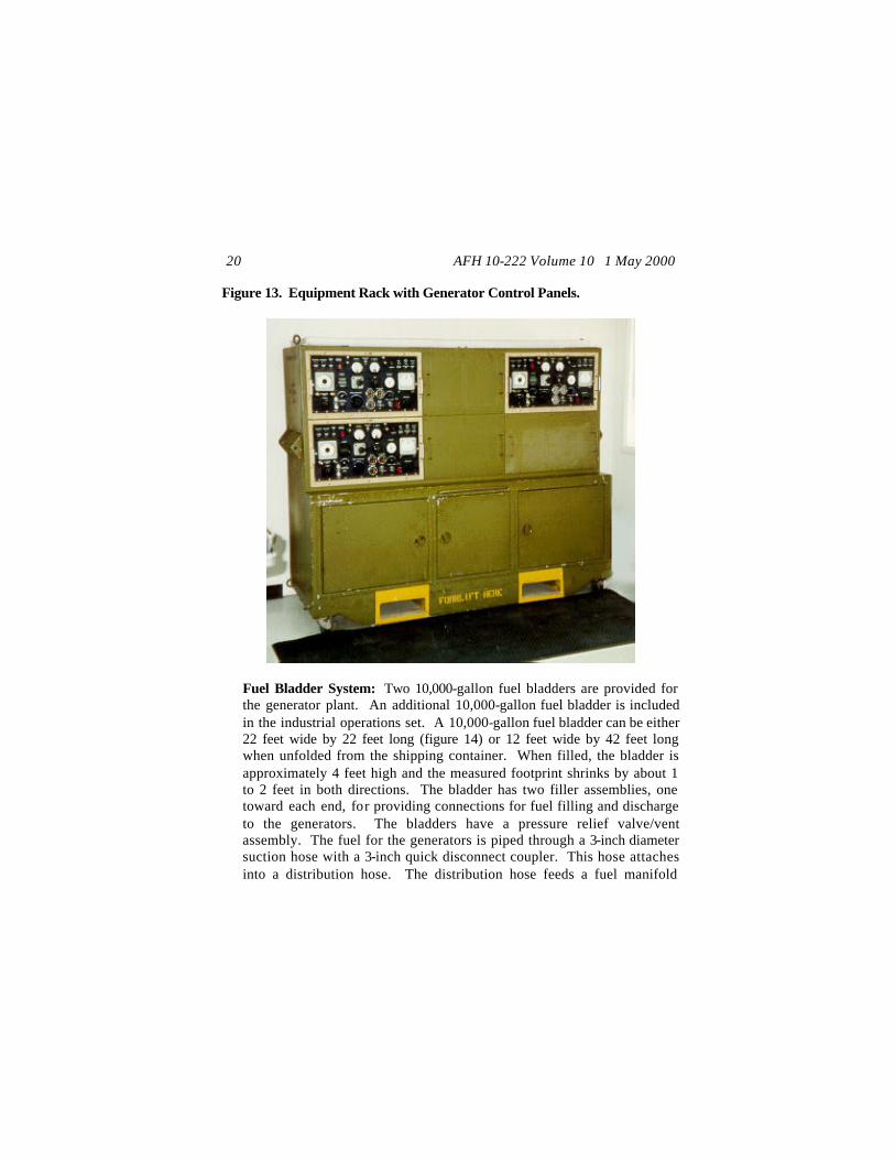
Equipment Rack: A MEP-12A's generator control panel can be removed from the generator and moved to a remote location using a 150-foot control cable. An equipment rack (figure 13) can hold up to four control panels for use as a centralized control room for power plant operations. The control room can be in a tent, an ESC (also included in UTC UFBEX), or a GP or other medium shelter.
AFH 10-222 Volume 10 1 May 2000 20
Figure 13. Equipment Rack with Generator Control Panels.
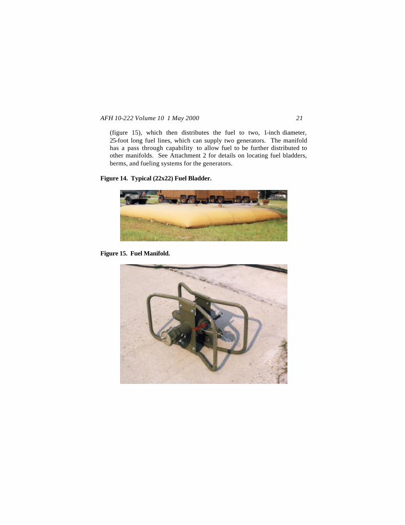
Fuel Bladder System: Two 10,000-gallon fuel bladders are provided for the generator plant. An additional 10,000-gallon fuel bladder is included in the industrial operations set. A 10,000-gallon fuel bladder can be either 22 feet wide by 22 feet long (figure 14) or 12 feet wide by 42 feet long when unfolded from the shipping container. When filled, the bladder is approximately 4 feet high and the measured footprint shrinks by about 1 to 2 feet in both directions. The bladder has two filler assemblies, one toward each end, for providing connections for fuel filling and discharge to the generators. The bladders have a pressure relief valve/vent assembly. The fuel for the generators is piped through a 3-inch diameter suction hose with a 3-inch quick disconnect coupler. This hose attaches into a distribution hose. The distribution hose feeds a fuel manifold
AFH 10-222 Volume 10 1 May 2000 21
(figure 15), which then distributes the fuel to two, 1-inch diameter, 25-foot long fuel lines, which can supply two generators. The manifold has a pass through capability to allow fuel to be further distributed to other manifolds. See Attachment 2 for details on locating fuel bladders, berms, and fueling systems for the generators.
Figure 14. Typical (22x22) Fuel Bladder.
Figure 15. Fuel Manifold.

AFH 10-222 Volume 10 1 May 2000 22
Important Ancillary Components Associated with Electrical Distribution System.
Remote Area Lighting System (RALS): The RALS is used to provide general, wide area lighting to larger facilities or operations, such as the flightline and Power, POL, and LOX plants. The RALS has 250 feet of service cable and may be supported by either a SDC or MEP generator. A RALS contains 13 telescopic two-lamp light poles, four 375-foot cable sets, and an aluminum container/control box. Light poles are spaced every 125 feet along the cable sets. Environmental Control Unit (ECU): The ECU is a heat-pump-type air conditioner and heater that is widely used with most shelters and tents. When a bare base requires the use of ECUs, then the load planning factors for generators and the HF EDS are greatly increased. The result is that many fewer facilities can be supported by each SDC in order to provide power to each facility's ECU.
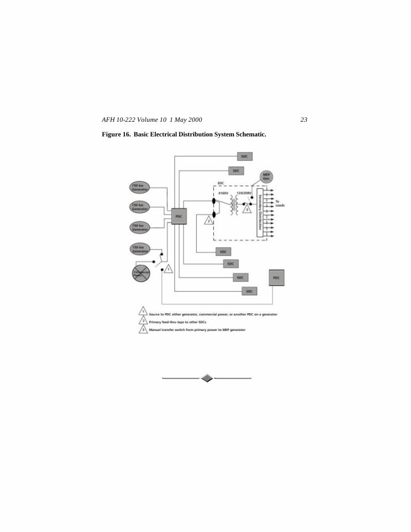
System Composition When all the system components are placed together, they create an electrical system with three categories of operation: Generation, High Voltage Power Distribution, and Secondary Distribution. The system components are tied together with high voltage cable using load break elbows from the MEP-12A generator through the PDC to the SDC and secondary voltage cable with cannon plugs from the SDC to the user's PDP or service panel. A typical electrical distribution system is depicted in the schematic (figure 16). The schematic and note 1 of figure 16 depict that an input can be made from either a MEP-12A generator, the output side feeders of another PDC, or from a commercial power source.
AFH 10-222 Volume 10 1 May 2000 23
Figure 16. Basic Electrical Distribution System Schematic.
AFH 10-222 Volume 10 1 May 2000 24
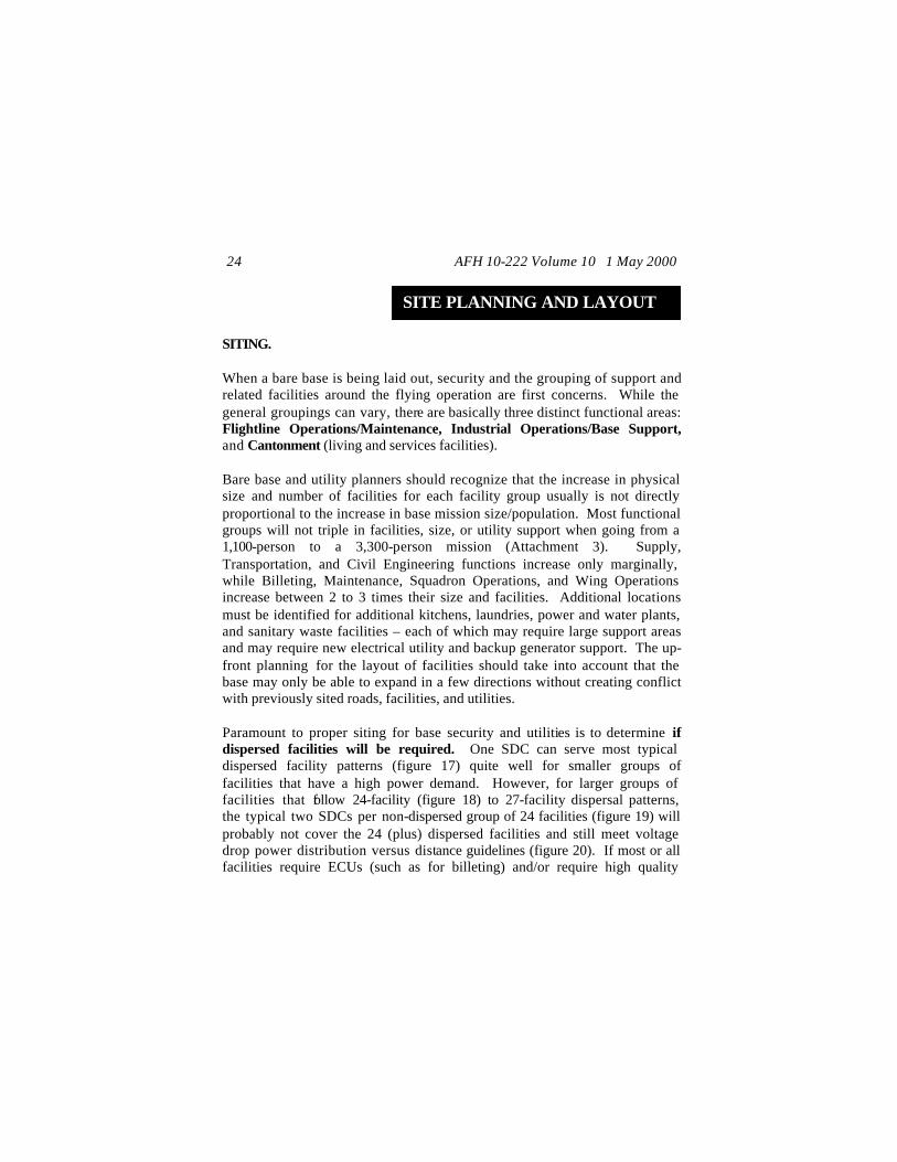
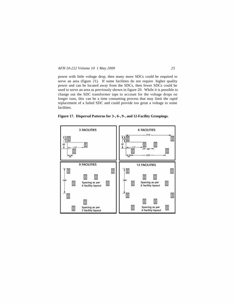
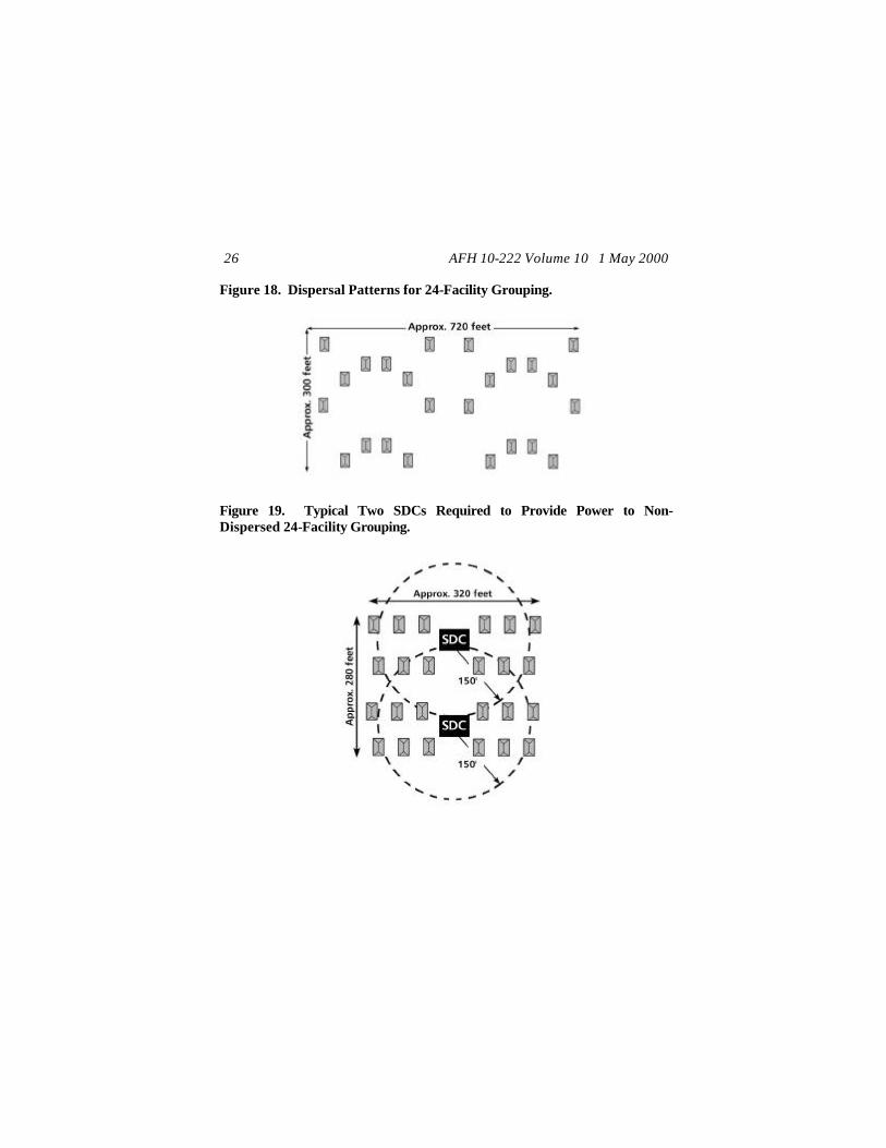
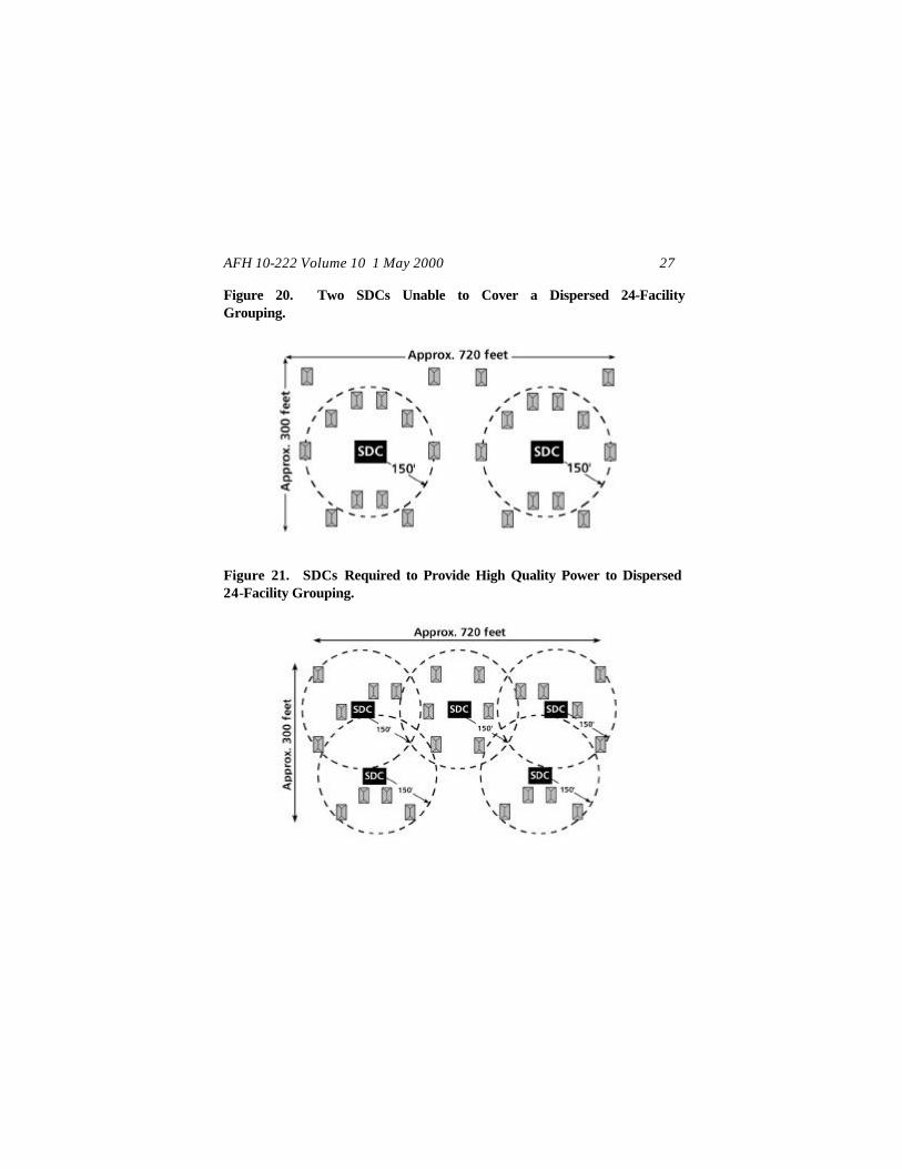
SITE PLANNING AND LAYOUT SITING. When a bare base is being laid out, security and the grouping of support and related facilities around the flying operation are first concerns. While the general groupings can vary, there are basically three distinct functional areas: Flightline Operations/Maintenance, Industrial Operations/Base Support, and Cantonment (living and services facilities). Bare base and utility planners should recognize that the increase in physical size and number of facilities for each facility group usually is not directly proportional to the increase in base mission size/population. Most functional groups will not triple in facilities, size, or utility support when going from a 1,100-person to a 3,300-person mission (Attachment 3). Supply, Transportation, and Civil Engineering functions increase only marginally, while Billeting, Maintenance, Squadron Operations, and Wing Operations increase between 2 to 3 times their size and facilities. Additional locations must be identified for additional kitchens, laundries, power and water plants, and sanitary waste facilities – each of which may require large support areas and may require new electrical utility and backup generator support. The up-front planning for the layout of facilities should take into account that the base may only be able to expand in a few directions without creating conflict with previously sited roads, facilities, and utilities. Paramount to proper siting for base security and utilities is to determine if dispersed facilities will be required. One SDC can serve most typical dispersed facility patterns (figure 17) quite well for smaller groups of facilities that have a high power demand. However, for larger groups of facilities that follow 24-facility (figure 18) to 27-facility dispersal patterns, the typical two SDCs per non-dispersed group of 24 facilities (figure 19) will probably not cover the 24 (plus) dispersed facilities and still meet voltage drop power distribution versus distance guidelines (figure 20). If most or all facilities require ECUs (such as for billeting) and/or require high quality
AFH 10-222 Volume 10 1 May 2000 25
power with little voltage drop, then many more SDCs could be required to serve an area (figure 21). If some facilities do not require higher quality power and can be located away from the SDCs, then fewer SDCs could be used to serve an area as previously shown in figure 20. While it is possible to change out the SDC transformer taps to account for the voltage drops on longer runs, this can be a time consuming process that may limit the rapid replacement of a failed SDC and could provide too great a voltage to some facilities. Figure 17. Dispersal Patterns for 3-, 6-, 9-, and 12-Facility Groupings.
AFH 10-222 Volume 10 1 May 2000 26
Figure 18. Dispersal Patterns for 24-Facility Grouping.
Figure 19. Typical Two SDCs Required to Provide Power to Non-Dispersed 24-Facility Grouping.
AFH 10-222 Volume 10 1 May 2000 27
Figure 20. Two SDCs Unable to Cover a Dispersed 24-Facility Grouping.
Figure 21. SDCs Required to Provide High Quality Power to Dispersed 24-Facility Grouping.
AFH 10-222 Volume 10 1 May 2000 28
Bare base officials and site planners need to examine the threat and determine with the air base defense (ABD) forces if dispersal is the best means for protection. Even in higher threat areas, the topography, enemy capabilities, and the base defense force measures (such as use of force protection and CCD techniques) may allow semi- or non-dispersed facility patterns within groups to be used much more effectively with wider group separation distances. Eliminating unnecessary terrain with priority targets is a consideration, as it may requires more ABD forces to defend. Having fewer widely dispersed facilities within a group also gives added flexibility to ABD forces, providing greater control for lines of sight and avenues of approach to non-dispersed and/or critical resources. SITE PLANNING. By the time most power production and electrical personnel begin arriving on site to set up the power plant and electrical distribution system, the basic site planning and paper layout for the bare base may well have been accomplished. Sectors and basic planning modules of facility groupings will have been designated for air base operations, support, and defense. If a bare base is being established with a view toward expansion from preliminary Harvest Eagle 550-person package or a Harvest Falcon 1,100-person package to a 2,200-, 3,300-, 4,400-, or even a 5,500-person package, then growth needs to be addressed during all stages. Therefore, the layout of individual facilities during the initial stages of layout should also take into account the growth of the utility systems. For those installing the HF EDS, you need to consider the timelines for installation and growth, the HF assets available to you at each stage of growth (and whether additional assets are needed/available), and the duration of the deployment. These considerations will affect the installation decisions you plan for during installation and the operating and expansion capabilities you (or your successor(s)) will have to live with. Decide up front where to specifically locate the major electrical components within the time frames and resources you are given to meet the deployment. Note that the typical deployment timelines are being updated to match the Aerospace

AFH 10-222 Volume 10 1 May 2000 29
Expeditionary Force (AEF) requirements for deployment. Expect to see changes in deployment criteria from the previous deployment timelines of:
Initial Stage: Support of initial flying operations (i.e., usually occurs the first 3 days (2 days for AEF)) and Intermediate Stage: Establishing the power plants and installing (above ground) the electrical distribution system (i.e., usually occurs the next 7 days).
While there are other electrical requirements that civil engineers must support during the intermediate stage, your primary electrical concern is to establish a base power system and connect facilities to it as the facilities are erected. Upon arrival and during the beginning of the deployment, start developing the issues regarding what kind of a power system will be needed. Example issues are:
If the threat is low and the size of the base is only a 1,100-person package, then one centralized power plant may be all that is needed. If facility dispersal is required, then two power plants will probably be required to cover the extended area. If two plants are required, are there enough PDCs available for dispersed plants? Can plants be set up to allow a PDC connection between power plants? Is there enough cable to connect between the separated power plants? Can SDCs from the separate plants be located close enough to quickly lay and park cable between critical SDCs for redundancy?
For a 1,100-person package, these issues may be easily addressed after rechecking the facility groupings, loads, and layouts. However, the situation

AFH 10-222 Volume 10 1 May 2000 30
can become increasingly complicated when you throw in additional transient aircraft and personnel support and/or begin beddown expansions above 3,300 persons, especially if dispersal is required. The larger the size of the area to be served, the more resources required for setup, support, and security. Throughout the planning, installation, and operation, determine the system power factors and how they may affect your power plant operations. Consider the following basic limiting factors when laying out the electrical system and using only the Harvest Falcon assets available during the initial and intermediate stage installation. These system limitations are based on transmission and distribution distances from the generators to the PDC, the PDC to the SDCs, and the SDCs to the PDPs. Basic system limitations are:
Primary (high voltage) power cable length limits:
From the Generators to the PDC: Limit the run to 25 feet with two generators and the farthest run to 80 feet with four generators. This is to keep the primary run as short as possible since there are no ground fault protective devices between the generators and the PDC. From the PDC to the SDCs (where the SDCs are grouped at the end of the run): Limit the run to 1.0 mile. A 1-mile run may still experience excessive voltage drops, but some of this can be compensated for with the tap settings of the SDC. To avoid changing tap settings, limit the length of a run from the PDC to the SDCs to 4,000 feet. From the PDC to the SDCs (where the SDCs are equally distributed along the run): Limit the run to 2.0 miles. Again, a 2-mile run may experience excessive voltage drop that requires SDC tap changes. To avoid changing tap settings, limit the length of a run from the PDC to the SDCs to 1.5 miles.

AFH 10-222 Volume 10 1 May 2000 31
Secondary (low voltage) power:
From SDCs to PDPs and facility distribution panels : Limit the run lengths to 150 feet when it is necessary to keep the voltage drop below 10% for the serviced facility. Runs of up to 800 feet may be made for emergency use and use with resistance type equipment less susceptible to voltage drops.
Electrical distribution schematic. When the overall base-planning layout is being developed, an electrical distribution schematic should be a major component for bare base support. During the beddown process, planners, power production, and electrical personnel need to calculate, determine, and/or identify load factors, demand, maximum draw, and diversified load, as related to individual facility groups. The specific information is used to develop the detailed secondary distribution schedule, placement of MEP generators, and develop the individual feeder schedules used for installation. Given time and expertise, going into this amount of detail during the initial beddown planning will significantly limit the need to relocate SDCs, re-site/relocate facilities, and relocate cable runs. During initial planning, basic planning factors can be followed to help minimize reaccomplishing work. However, the detailed schedules should still be accomplished prior to installation of the HF EDS. Basic electrical planning factors. During normal operations, not every MEP-12A will be running full time at full power. The system design should take into consideration the number of generators that will be running full time at full power for each power plant. For a 1,100-person base, there may be three or four generators at a main base plant and one or two generators at the flightline plant. At a flightline plant with two generators, only one generator may be required for 24-hour operations. At the main plant with three generators, only one may be

AFH 10-222 Volume 10 1 May 2000 32
required to operate at full load during the night. For deployments where environmental control units have to sustain continuous loads (at a 26-amp draw), you must consider the maximum load that one generator can support through the PDC and SDCs.
For SDCs, the total load on each SDC should not exceed 150 kVA and the load on each SDC circuit should not exceed 21.6 kVA. Under maximum operating loads when facilities have ECUs, one 750 kW generator (operating at 80% of its maximum) will support through the PDC no more than 30 SDCs total (5 SDCs per each of the 6 single 200-amp PDC circuits). Under normal operating loads, a power plant with at least two 750 kW generators operating will support through the PDC 6 to 10 SDCs per PDC circuit when facilities have ECUs and 10 to 15 SDCs per PDC circuit when facilities do not have ECUs.
Note: By properly balancing the number of SDCs per plant, the number of SDCs per PDC should not exceed this maximum number, since the number of SDCs available for 1,100-, 2,200-, and 3,300-person deployments is 32, 56, and 80 respectively.
For each SDC, the remaining available power for other use within shelters (when ECUs are required) is:
12 shelters (maximum) provide 35 amps per shelter of usable power (9 amps per phase). 10 shelters provide 41amps per shelter of usable power (15 amps per phase). 7 shelters provide 60 amps per shelter of usable power (34 amps per phase).
Warning: For ambient temperatures of more than 125°° F, do not operate the SDC at more than 80% load (i.e., no more than 12 of 16 output connections used).

AFH 10-222 Volume 10 1 May 2000 33
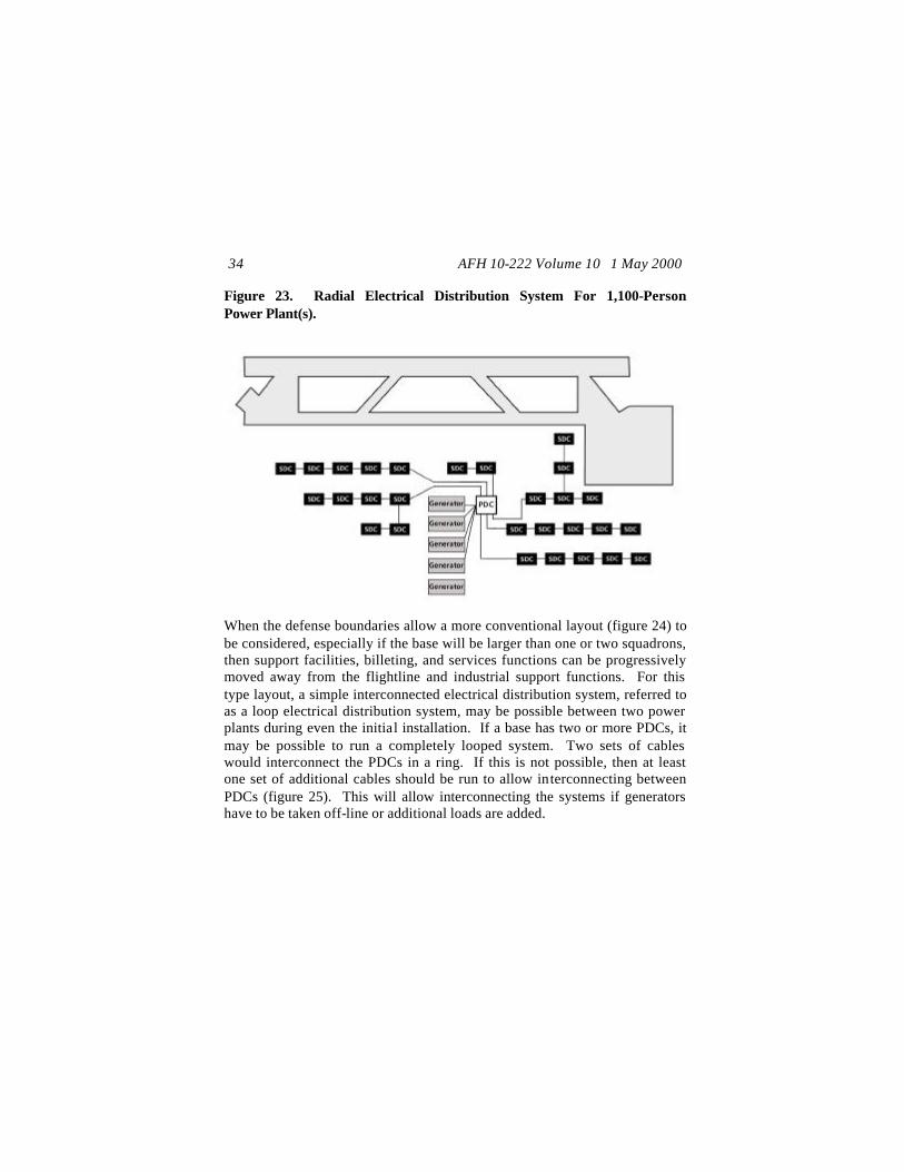
Note: The current bare base ECU draws 26 amps at full load. If new equipment, such as the field deployable environmental control unit (FDECU), has a higher operating load, then planning factors should be adjusted for deployment locations that receive the newer equipment. This may require obtaining additional generators, PDCs, SDCs, and cable. LAYOUT. Layout decisions must consider the threat, the type of system to be installed (radial or loop), and the expected final size of the bare base being supported. Most bare bases with a recognized threat have to first consider the basic structure of a bare base from an air base defense point-of-view combined with the normal base operating requirements. In many cases, the tactical area of responsibility (TAOR) boundary for base defense may dictate the initial installation pattern for the electrical system. For some locations, the TAOR dictated base structure may be linear (figure 22), that is it must be designed along a flightline such that the base is long and narrow. In this case, a radial (i.e., linear) electrical distribution system (figure 23) may initially be required, such as for installation of a 1,100-person bare base. Figure 22. Linear Base Layout.
AFH 10-222 Volume 10 1 May 2000 34
Figure 23. Radial Electrical Distribution System For 1,100-Person Power Plant(s).
When the defense boundaries allow a more conventional layout (figure 24) to be considered, especially if the base will be larger than one or two squadrons, then support facilities, billeting, and services functions can be progressively moved away from the flightline and industrial support functions. For this type layout, a simple interconnected electrical distribution system, referred to as a loop electrical distribution system, may be possible between two power plants during even the initial installation. If a base has two or more PDCs, it may be possible to run a completely looped system. Two sets of cables would interconnect the PDCs in a ring. If this is not possible, then at least one set of additional cables should be run to allow interconnecting between PDCs (figure 25). This will allow interconnecting the systems if generators have to be taken off-line or additional loads are added.
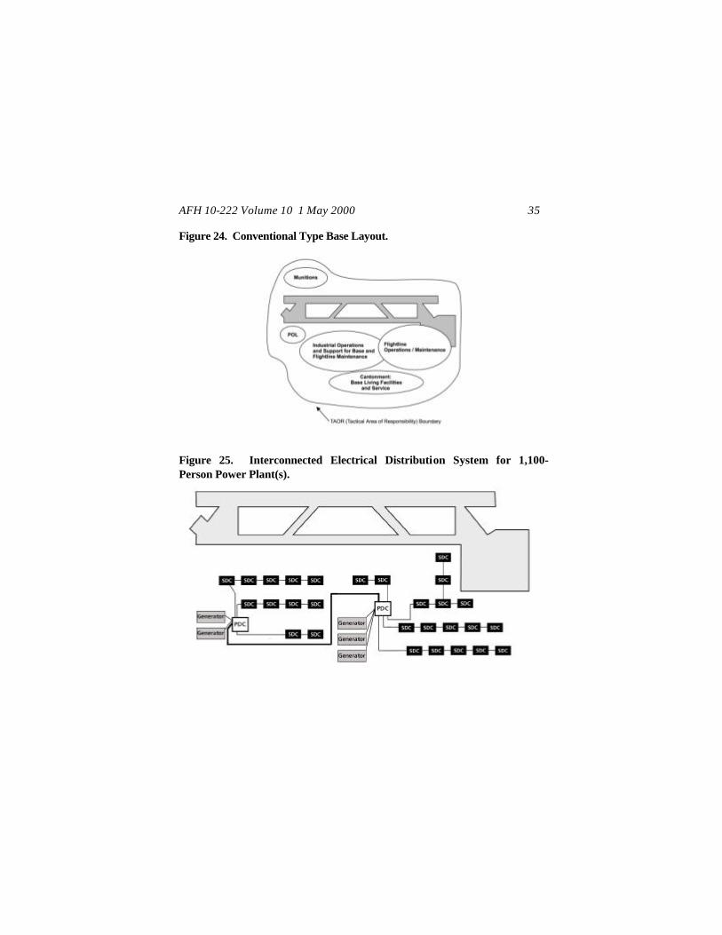
AFH 10-222 Volume 10 1 May 2000 35
Figure 24. Conventional Type Base Layout.
Figure 25. Interconnected Electrical Distribution System for 1,100-Person Power Plant(s).
AFH 10-222 Volume 10 1 May 2000 36
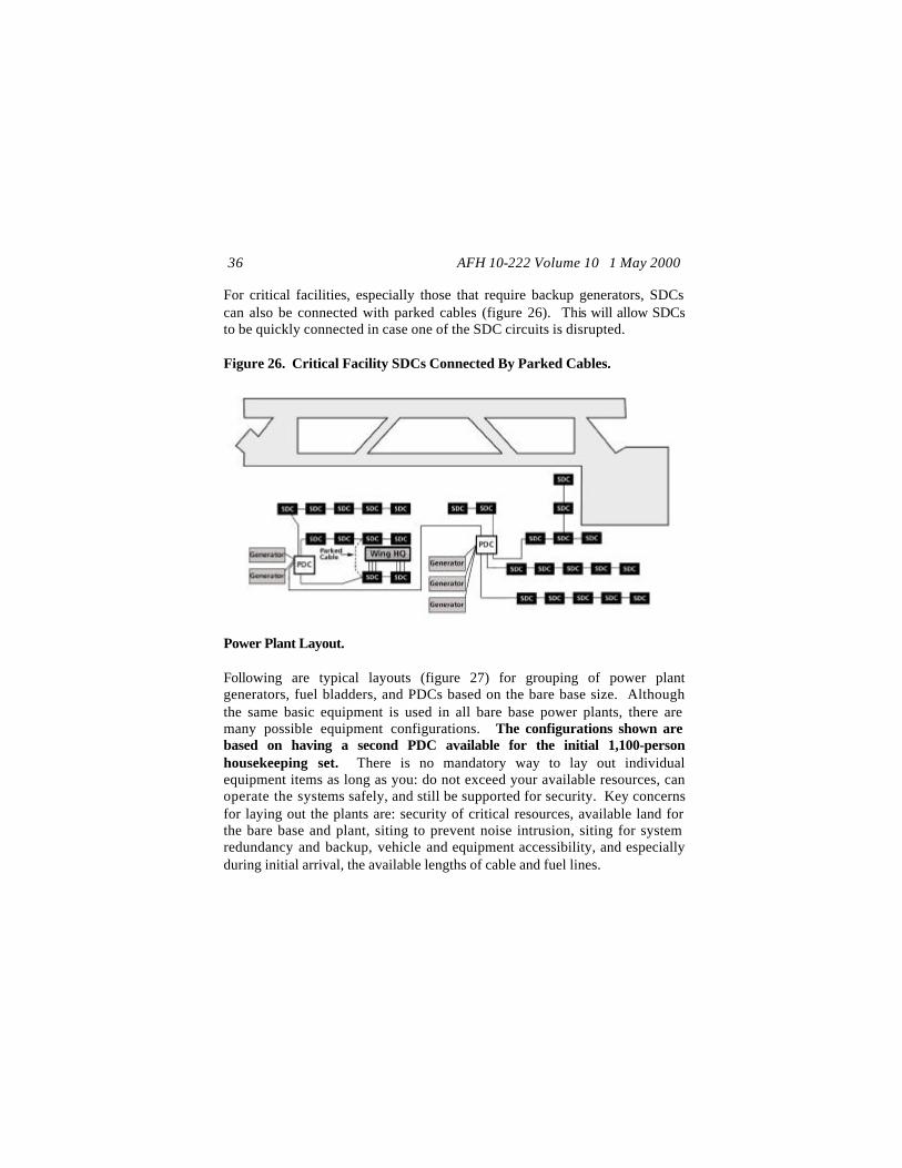
For critical facilities, especially those that require backup generators, SDCs can also be connected with parked cables (figure 26). This will allow SDCs to be quickly connected in case one of the SDC circuits is disrupted. Figure 26. Critical Facility SDCs Connected By Parked Cables.
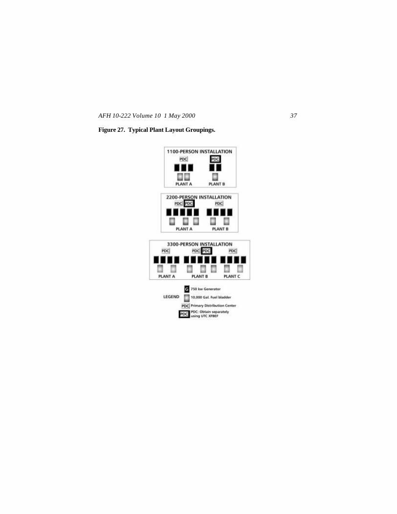
Power Plant Layout. Following are typical layouts (figure 27) for grouping of power plant generators, fuel bladders, and PDCs based on the bare base size. Although the same basic equipment is used in all bare base power plants, there are many possible equipment configurations. The configurations shown are based on having a second PDC available for the initial 1,100-person housekeeping set. There is no mandatory way to lay out individual equipment items as long as you: do not exceed your available resources, can operate the systems safely, and still be supported for security. Key concerns for laying out the plants are: security of critical resources, available land for the bare base and plant, siting to prevent noise intrusion, siting for system redundancy and backup, vehicle and equipment accessibility, and especially during initial arrival, the available lengths of cable and fuel lines.
AFH 10-222 Volume 10 1 May 2000 37
Figure 27. Typical Plant Layout Groupings.

AFH 10-222 Volume 10 1 May 2000 38
Typical Facility Groups. Harvest Falcon deployment packages are standardized for the types of facility structures that serve each functional groupings. For planning purposes, the functional groupings vary little and carry a common designation. Following are basic designations for facility groups and the types of structures supplied to house major functions (Tables 1 and 2). Table 1. 1,100-Person Bare Base Facility List.
Area Facility Group Structure Type TEMP ESC GPS ACH FSTFS
A AVIONICS 1 3 B1, B2,
BILLETING and SERVICES ADMIN (billeting may be subdivided into Enlisted, Female, and Officer designations)
105
C CHAPEL 1 D1 SERVICES (DINING HALL) 1(9-1) E ENGINEER 14 1 3 F MAINTENANCE 4 10 5 2 1 G SQUADRON OPERATIONS 1 1 1 H SUPPORT GROUP 8 5 2 I EMERGENCY SERVICES 10 J AERIAL PORT 3 L LAUNDRY 2 M MUNITIONS 1 3 P POL 1 1 R ALERT 3 S SUPPLY 2 2 7 T TRANSPORTATION 2 3 W WING OPERATIONS 10 3 X HOSPITAL Y COMMUNICATIONS Z AIRFIELD FACILITIES
EW1, EW2
WATER PLANT(s) 2
AFH 10-222 Volume 10 1 May 2000 39
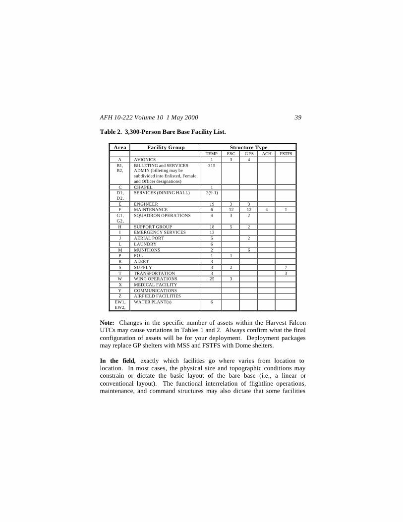
Table 2. 3,300-Person Bare Base Facility List.
Area Facility Group Structure Type TEMP ESC GPS ACH FSTFS
A AVIONICS 1 3 4 B1, B2,
BILLETING and SERVICES ADMIN (billeting may be subdivided into Enlisted, Female, and Officer designations)
315
C CHAPEL 1 D1, D2,
SERVICES (DINING HALL) 2(9-1)
E ENGINEER 19 3 3 F MAINTENANCE 6 12 12 4 1
G1, G2,
SQUADRON OPERATIONS 4 3 2
H SUPPORT GROUP 18 5 2 I EMERGENCY SERVICES 13 J AERIAL PORT 5 2 L LAUNDRY 6 M MUNITIONS 2 6 P POL 1 1 R ALERT 3 S SUPPLY 3 2 7 T TRANSPORTATION 3 3 W WING OPERATIONS 25 3 X MEDICAL FACILITY Y COMMUNICATIONS Z AIRFIELD FACILITIES
EW1, EW2,
WATER PLANT(s) 6
Note: Changes in the specific number of assets within the Harvest Falcon UTCs may cause variations in Tables 1 and 2. Always confirm what the final configuration of assets will be for your deployment. Deployment packages may replace GP shelters with MSS and FSTFS with Dome shelters. In the field, exactly which facilities go where varies from location to location. In most cases, the physical size and topographic conditions may constrain or dictate the basic layout of the bare base (i.e., a linear or conventional layout). The functional interrelation of flightline operations, maintenance, and command structures may also dictate that some facilities

AFH 10-222 Volume 10 1 May 2000 40
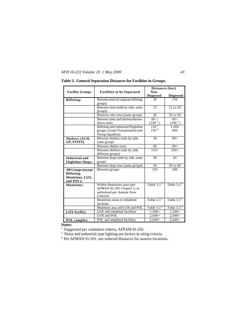
and functions are collocated differently, especially if the base supports other US or allied military services. Prior to deployment, even when no deployment is identified, all bases, which could deploy as a unit, should identify ahead of time and practice the layout of functional areas based on which units (both within and between large facility groups) must function in close proximity to each other. Site planners need this information to effectively function in the field during the critical first ten days of the deployment. This will also allow power production and electrical shop personnel to train on laying out distribution systems and calculating requirements for secondary distribution and feeder schedules. Using standard (general) guidelines for separation of facilities (Table 3), the cable that is provided with the Harvest Falcon deployment package is adequate for initial installation on bases if most assets/facilities are not dispersed (figure 28). However, if facilities within groups must be dispersed at the maximum distances indicated in Table 3 due to high threat conditions, then either some non-critical facilities may require MEP generator support or additional primary and secondary cable and connectors may be required to meet dispersal distances. Be aware that required separation criteria for some facilities (such as Munitions, POL, and LOX) can be varied based on terrain, protection of assets, and mission/weapons systems. The specific separation distances should be determined for the individual base. This could have a major impact on the layout of power plants, SDCs, and MEP generators.
AFH 10-222 Volume 10 1 May 2000 41
Table 3. General Separation Distances for Facilities in Groups.
Facility Groups
Facilities to be Separated
Distances (feet) Non- Dispersed Dispersed
Billeting: Between tents (in separate billeting groups)
30 150
Between tents (side by side, same group))
12 12 to 20
Between tent rows (same group) 30 30 to 60 Between tents and latrines/shower-
shave units 60 +
(100 1 ) 60+
(100 1 ) Billeting and Industrial/Flightline
groups, except Transportation and Flying Squadrons
150 2 150 2
1,600 900
Shelters (ACH, GP, FSTFS):
Between shelters (side by side, same group)
30 60+
Between shelter rows 60 60+ Between shelters (side by side,
different groups) 150+ 200+
Industrial and Flightline Shops:
Between shops (side by side, same group)
30 60
Between shop rows (same groups) 30 30 to 60 All Groups (except Billeting, Munitions, LOX, and POL):
Between groups 150 200
Munitions: Within Munitions area (per AFMAN 91-201 Chapter 3, as authorized per Austere Area Criteria)
Table 3.3 3 Table 3.3 3
Munitions areas to inhabited facilities
Table 3.3 3 Table 3.3 3
Munitions area and LOX and POL Table 3.3 3 Table 3.3 3 LOX facility: LOX and inhabited facilities 1,500+ 1,500+ LOX and POL 2,640+ 2,640+ POL complex: POL and inhabited facilities 2,640+ 2,640+
Notes: 1 Suggested per sanitation criteria, AFPAM 91-216. 2 Noise and industrial type lighting are factors in siting criteria. 3 Per AFMAN 91-201, see reduced distances for austere locations.
AFH 10-222 Volume 10 1 May 2000 42
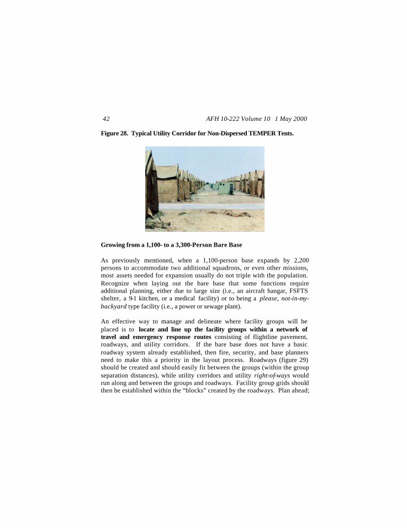
Figure 28. Typical Utility Corridor for Non-Dispersed TEMPER Tents.
Growing from a 1,100- to a 3,300-Person Bare Base As previously mentioned, when a 1,100-person base expands by 2,200 persons to accommodate two additional squadrons, or even other missions, most assets needed for expansion usually do not triple with the population. Recognize when laying out the bare base that some functions require additional planning, either due to large size (i.e., an aircraft hangar, FSFTS shelter, a 9-1 kitchen, or a medical facility) or to being a please, not-in-my-backyard type facility (i.e., a power or sewage plant). An effective way to manage and delineate where facility groups will be placed is to locate and line up the facility groups within a network of travel and emergency response routes consisting of flightline pavement, roadways, and utility corridors. If the bare base does not have a basic roadway system already established, then fire, security, and base planners need to make this a priority in the layout process. Roadways (figure 29) should be created and should easily fit between the groups (within the group separation distances), while utility corridors and utility right-of-ways would run along and between the groups and roadways. Facility group grids should then be established within the “blocks” created by the roadways. Plan ahead;

AFH 10-222 Volume 10 1 May 2000 43
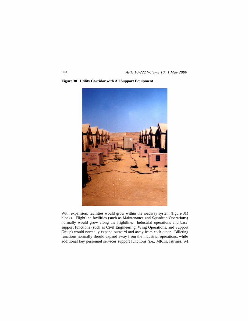
orient the tents/shelters and maintain adequate distances between each tent/shelter to allow room for ECUs and other utilities. Otherwise, utility corridors can become cluttered with equipment (figure 30), which will make repairs, maintenance, emergency response, and removal of equipment much harder. Map Symbol for Facility Groups A Avionics EW1,2… Water Plant(s) P POL B1,2.. Billeting F Maintenance R Alert C Chaplain G1,2… Squadron Ops S Supply D1,2.. Dining Hall H Support Group T Transportation E Engineering I Emergency Svcs W Wing HQ EP1,2... Power Plant(s) J Aerial Port X Medical Fac. ES1,2.. Sewage Treatment L Laundry Y Communications
Plant(s) M Munitions Figure 29. Typical 1,100-Person Layout with Major Roadway Grid.
AFH 10-222 Volume 10 1 May 2000 44
Figure 30. Utility Corridor with All Support Equipment.
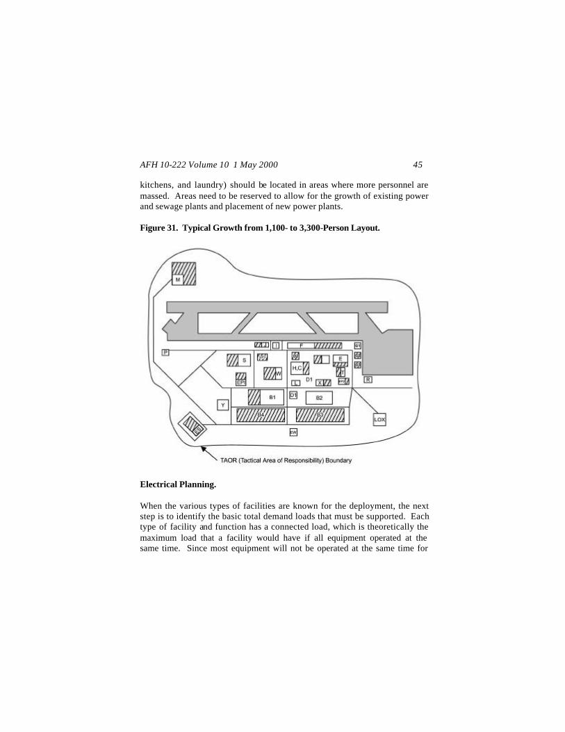
With expansion, facilities would grow within the roadway system (figure 31) blocks. Flightline facilities (such as Maintenance and Squadron Operations) normally would grow along the flightline. Industrial operations and base support functions (such as Civil Engineering, Wing Operations, and Support Group) would normally expand outward and away from each other. Billeting functions normally should expand away from the industrial operations, while additional key personnel services support functions (i.e., MKTs, latrines, 9-1
AFH 10-222 Volume 10 1 May 2000 45
kitchens, and laundry) should be located in areas where more personnel are massed. Areas need to be reserved to allow for the growth of existing power and sewage plants and placement of new power plants. Figure 31. Typical Growth from 1,100- to 3,300-Person Layout.
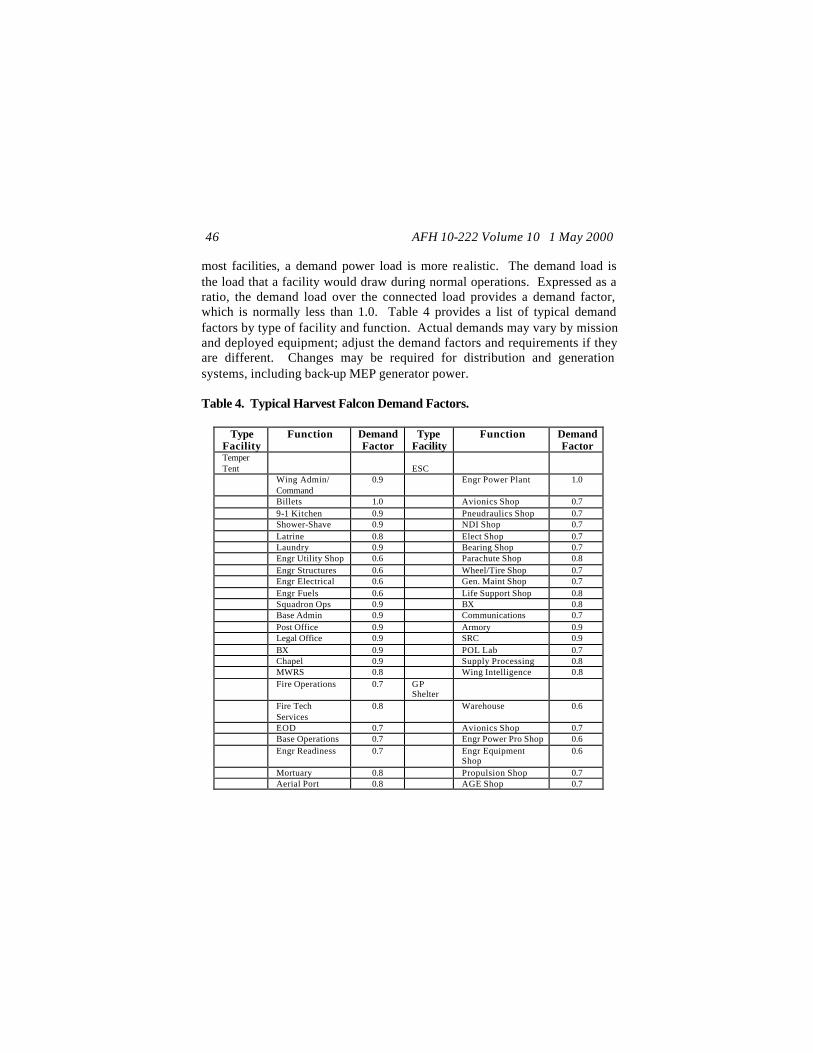
Electrical Planning. When the various types of facilities are known for the deployment, the next step is to identify the basic total demand loads that must be supported. Each type of facility and function has a connected load, which is theoretically the maximum load that a facility would have if all equipment operated at the same time. Since most equipment will not be operated at the same time for
AFH 10-222 Volume 10 1 May 2000 46
most facilities, a demand power load is more realistic. The demand load is the load that a facility would draw during normal operations. Expressed as a ratio, the demand load over the connected load provides a demand factor, which is normally less than 1.0. Table 4 provides a list of typical demand factors by type of facility and function. Actual demands may vary by mission and deployed equipment; adjust the demand factors and requirements if they are different. Changes may be required for distribution and generation systems, including back-up MEP generator power. Table 4. Typical Harvest Falcon Demand Factors.
Type Facility
Function Demand Factor
Type Facility
Function Demand Factor
Temper Tent
ESC
Wing Admin/ Command
0.9 Engr Power Plant 1.0
Billets 1.0 Avionics Shop 0.7 9-1 Kitchen 0.9 Pneudraulics Shop 0.7 Shower-Shave 0.9 NDI Shop 0.7 Latrine 0.8 Elect Shop 0.7 Laundry 0.9 Bearing Shop 0.7 Engr Utility Shop 0.6 Parachute Shop 0.8 Engr Structures 0.6 Wheel/Tire Shop 0.7 Engr Electrical 0.6 Gen. Maint Shop 0.7 Engr Fuels 0.6 Life Support Shop 0.8 Squadron Ops 0.9 BX 0.8 Base Admin 0.9 Communications 0.7 Post Office 0.9 Armory 0.9 Legal Office 0.9 SRC 0.9 BX 0.9 POL Lab 0.7 Chapel 0.9 Supply Processing 0.8 MWRS 0.8 Wing Intelligence 0.8 Fire Operations 0.7 GP
Shelter
Fire Tech Services
0.8 Warehouse 0.6
EOD 0.7 Avionics Shop 0.7 Base Operations 0.7 Engr Power Pro Shop 0.6 Engr Readiness 0.7 Engr Equipment
Shop 0.6
Mortuary 0.8 Propulsion Shop 0.7 Aerial Port 0.8 AGE Shop 0.7
AFH 10-222 Volume 10 1 May 2000 47
Type Facility
Function Demand Factor
Type Facility
Function Demand Factor
Alert Facility 0.9 Gen. Maint Shop 0.8 Vehicle Ops 0.7 Sqd Ops Support 0.7 TMO 0.7 Gen. Support 0.7 Wing Briefing 0.9 Aerial Port 0.8 Wing Ops/ Plans 0.8 Munitions Maint 0.7 Wing Intelligence 0.8 FSTFS Maint /Job
Control
0.8 Propulsion Shop 0.8
Maint Mat Control
0.7 Supply Storage 0.9
Maint QC 0.8 Vehicle Maintenance 0.7 ACH Packing/Crating 0.7 Hangar 0.9
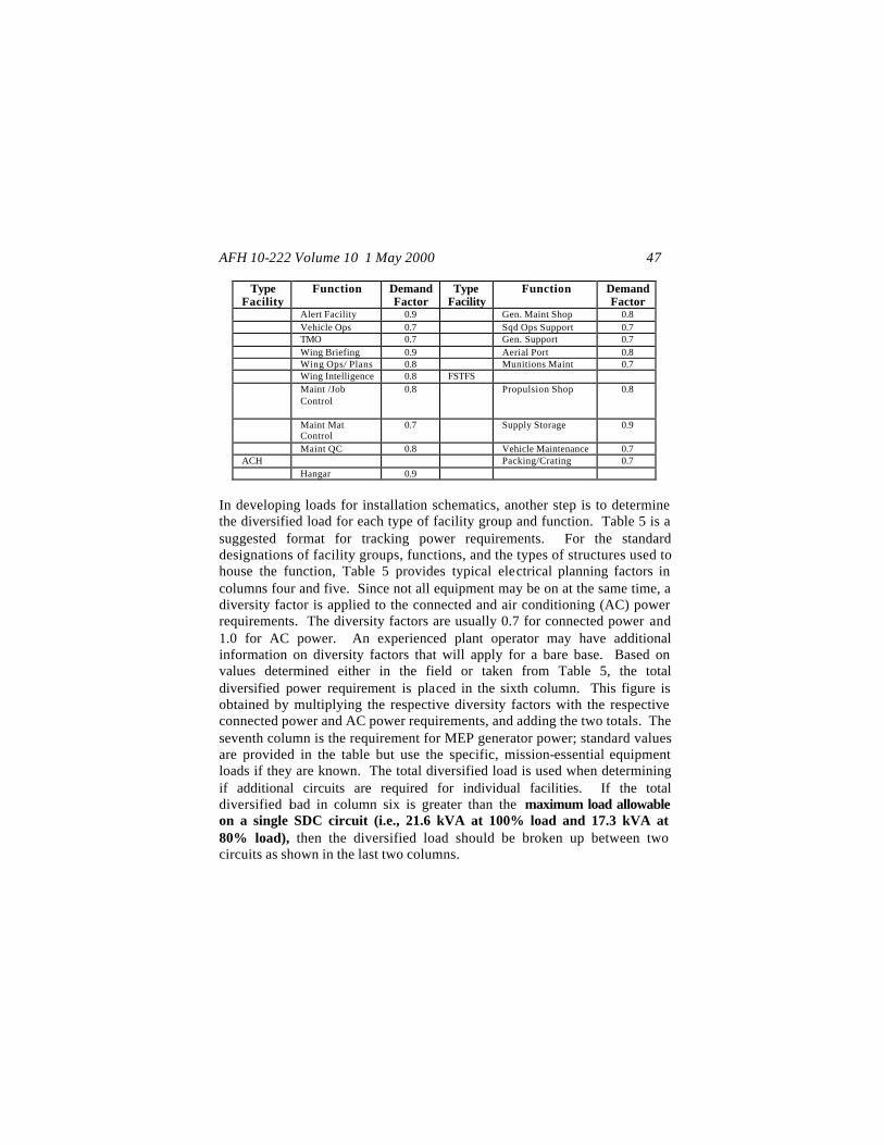
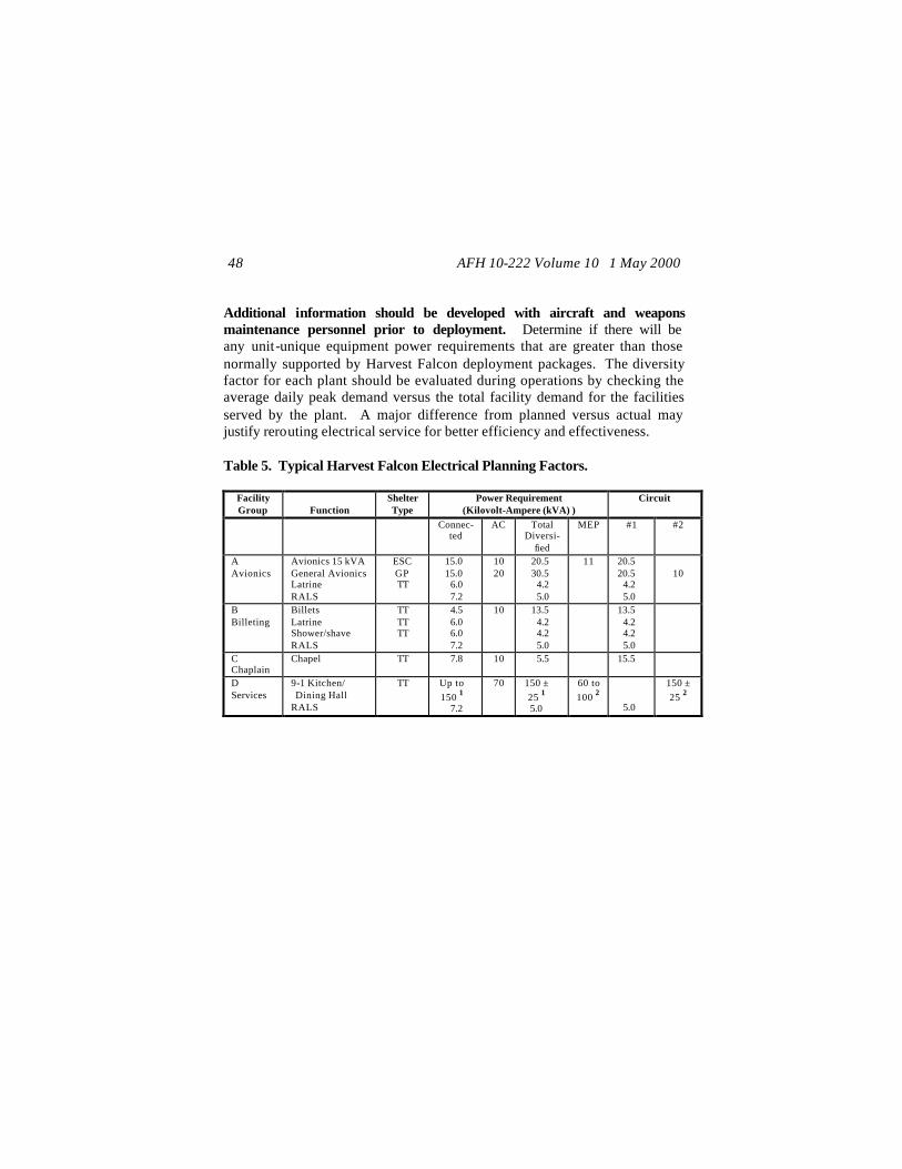
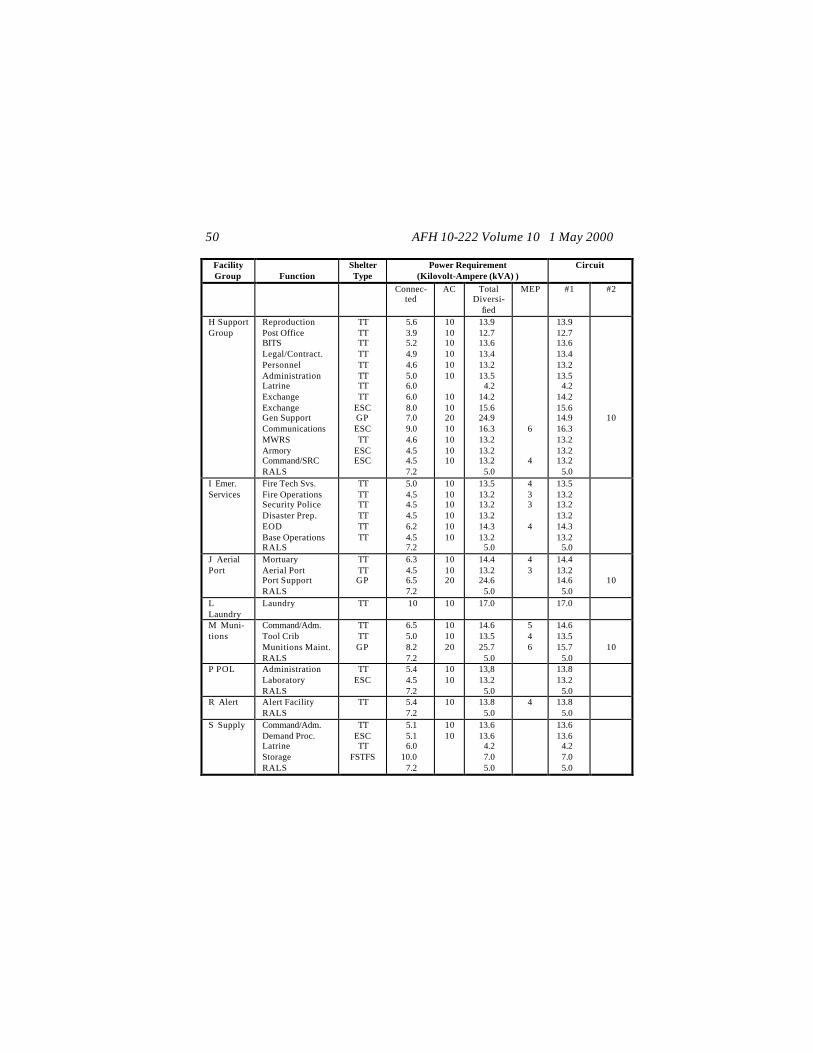
In developing loads for installation schematics, another step is to determine the diversified load for each type of facility group and function. Table 5 is a suggested format for tracking power requirements. For the standard designations of facility groups, functions, and the types of structures used to house the function, Table 5 provides typical electrical planning factors in columns four and five. Since not all equipment may be on at the same time, a diversity factor is applied to the connected and air conditioning (AC) power requirements. The diversity factors are usually 0.7 for connected power and 1.0 for AC power. An experienced plant operator may have additional information on diversity factors that will apply for a bare base. Based on values determined either in the field or taken from Table 5, the total diversified power requirement is placed in the sixth column. This figure is obtained by multiplying the respective diversity factors with the respective connected power and AC power requirements, and adding the two totals. The seventh column is the requirement for MEP generator power; standard values are provided in the table but use the specific, mission-essential equipment loads if they are known. The total diversified load is used when determining if additional circuits are required for individual facilities. If the total diversified load in column six is greater than the maximum load allowable on a single SDC circuit (i.e., 21.6 kVA at 100% load and 17.3 kVA at 80% load), then the diversified load should be broken up between two circuits as shown in the last two columns.
AFH 10-222 Volume 10 1 May 2000 48
Additional information should be developed with aircraft and weapons maintenance personnel prior to deployment. Determine if there will be any unit-unique equipment power requirements that are greater than those normally supported by Harvest Falcon deployment packages. The diversity factor for each plant should be evaluated during operations by checking the average daily peak demand versus the total facility demand for the facilities served by the plant. A major difference from planned versus actual may justify rerouting electrical service for better efficiency and effectiveness. Table 5. Typical Harvest Falcon Electrical Planning Factors.
Facility Group
Function
Shelter Type
Power Requirement (Kilovolt-Ampere (kVA) )
Circuit
Connec-ted
AC Total Diversi-
fied
MEP #1 #2
A Avionics
Avionics 15 kVA General Avionics Latrine RALS
ESC GP TT
15.0 15.0
6.0 7.2
10 20
20.5 30.5
4.2 5.0
11 20.5 20.5
4.2 5.0
10
B Billeting
Billets Latrine Shower/shave RALS
TT TT TT
4.5 6.0 6.0 7.2
10 13.5 4.2 4.2 5.0
13.5 4.2 4.2 5.0
C Chaplain
Chapel TT 7.8 10 5.5 15.5
D Services
9-1 Kitchen/ Dining Hall RALS
TT Up to 150 1
7.2
70 150 ± 25 1 5.0
60 to 100 2
5.0
150 ± 25 2

AFH 10-222 Volume 10 1 May 2000 49
Facility Group
Function
Shelter Type
Power Requirement (Kilovolt-Ampere (kVA) )
Circuit
Connec-ted
AC Total Diversi-
fied
MEP #1 #2
E Engineer
Eng Command Eng Mngmt Mat. Control Eng Operations Utilities Structures HVAC Fuels Electrical Entomology Power Pro Equipment Power Pro Water Plant Latrine Eng Support RALS
TT TT TT TT TT TT TT TT TT TT GP GP ESC TT TT GP
5.2 4.9 7.0 4.6 5.8
11.6 7.8 7.2 7.3 5.8 9.7 6.9 5.8 5.0 6.0 6.9 7.0
10 10 10 10 10 10 10 10 10 10 20 20 10 10
20
13.6 13.4 14.9 13.2 14.1 18.1 15.5 15.0 15.1 14.1 26.8 14.8 14.1 13.5
4.2 24.8
5.0
3
13.6 13.4 14.9 13.2 14.1 18.1 15.5 15.0 15.1 14.1 16.8 14.8 14.1 13.5
4.2 14.8
5.0
10 10
10
F Mainte-nance
Pneudraulics NDI Propulsion Propulsion Electrical Bearing Clean AGE Command/Adm. Parachute Hangar Wheel/Tire Latrine Gen Maint Sup. Gen Maint Sup. RALS
ESC ESC
FSTFS GP ESC ESC GP TT
ESC ACH ESC TT GP ESC
28.1 7.7
36.0 15.0 15.6
5.8 8.2 6.2 6.6
36.0 6.0 6.0
10.0 8.0 7.2
10 10
20 10 10 20 10 10
10
20 10
29.7 15.4 25.2 30.5 20.9 14.1 25.7 14.3 14.6 25.2 14.2
4.2 27.0 15.6
5.0
20
21 10 11
6 4 5 25
19.7 15.4 15.2 20.5 20.9 14.1 15.7 14.3 14.6 15.2 14.2
4.2 17.0 15.6
5.0
10
10 10
10
10
10
G Squad Ops
Squadron Ops. Life Support Latrine Squad Ops. Sup. RALS
TT ESC TT GP
5.9 5.7 6.0 6.5 7.2
10 10
20
14.1 14.0
4.2 24.6
5.0
4 4
14.1 14.0
4.2 14.6
5.0
10
AFH 10-222 Volume 10 1 May 2000 50
Facility Group
Function
Shelter Type
Power Requirement (Kilovolt-Ampere (kVA) )
Circuit
Connec-ted
AC Total Diversi-
fied
MEP #1 #2
H Support Group
Reproduction Post Office BITS Legal/Contract. Personnel Administration Latrine Exchange Exchange Gen Support Communications MWRS Armory Command/SRC RALS
TT TT TT TT TT TT TT TT
ESC GP ESC TT
ESC ESC
5.6 3.9 5.2 4.9 4.6 5.0 6.0 6.0 8.0 7.0 9.0 4.6 4.5 4.5 7.2
10 10 10 10 10 10
10 10 20 10 10 10 10
13.9 12.7 13.6 13.4 13.2 13.5
4.2 14.2 15.6 24.9 16.3 13.2 13.2 13.2
5.0
6
4
13.9 12.7 13.6 13.4 13.2 13.5
4.2 14.2 15.6 14.9 16.3 13.2 13.2 13.2
5.0
10
I Emer. Services
Fire Tech Svs. Fire Operations Security Police Disaster Prep. EOD Base Operations RALS
TT TT TT TT TT TT
5.0 4.5 4.5 4.5 6.2 4.5 7.2
10 10 10 10 10 10
13.5 13.2 13.2 13.2 14.3 13.2
5.0
4 3 3
4
13.5 13.2 13.2 13.2 14.3 13.2
5.0
J Aerial Port
Mortuary Aerial Port Port Support RALS
TT TT GP
6.3 4.5 6.5 7.2
10 10 20
14.4 13.2 24.6
5.0
4 3
14.4 13.2 14.6
5.0
10
L Laundry
Laundry TT 10 10 17.0 17.0
M Muni-tions
Command/Adm. Tool Crib Munitions Maint. RALS
TT TT GP
6.5 5.0 8.2 7.2
10 10 20
14.6 13.5 25.7
5.0
5 4 6
14.6 13.5 15.7
5.0
10
P POL Administration Laboratory RALS
TT ESC
5.4 4.5 7.2
10 10
13,8 13.2
5.0
13.8 13.2
5.0
R Alert Alert Facility RALS
TT 5.4 7.2
10 13.8 5.0
4 13.8 5.0
S Supply Command/Adm. Demand Proc. Latrine Storage RALS
TT ESC TT
FSTFS
5.1 5.1 6.0
10.0 7.2
10 10
13.6 13.6
4.2 7.0 5.0
13.6 13.6
4.2 7.0 5.0

AFH 10-222 Volume 10 1 May 2000 51
Facility Group
Function
Shelter Type
Power Requirement (Kilovolt-Ampere (kVA) )
Circuit
Connec-ted
AC Total Diversi-
fied
MEP #1 #2
T Trans-portation
Vehicle Ops. TMO Latrine Vehicle Maint. Packing/Crating
TT TT TT
FSTFS FSTFS
4.5 4.5 6.0
18.5 12.0
10 10
13.2 13.2
4.2 13.0
8.4
13.2 13.2
4.2 13.0
8.4
W Wing Ops
Administration Briefing Plans Operations Targets Intelligence Intelligence Maint Command Job Control Material Control Quality Control Maint Analysis Maint Records Maint Plans Latrine Finance Command Post Command/Adm. RALS
TT TT TT TT TT TT
ESC TT TT TT TT TT TT TT TT TT
ESC ESC
5.7 7.0 4.5 4.6 4.5 5.6 5.6 4.5 4.8 6.3 6.3 4.5 4.5 6.3 6.0 4.5 7.0
5.77.2
10 10 10 10 10 10 10 10 10 10 10 10 10 10
10 10 10
14.0 14.9 13.2 13.2 13.2 13.9 13.9 13.2 13.4 14.4 14.4 13.2 13.2 14.4
4.2 13.2 14.0 14.0
5.0
5
3 4 4
4 4 4
4
14.0 14.9 13.2 13.2 13.2 13.9 13.9 13.2 13.4 14.4 14.4 13.2 13.2 14.4
4.2 13.2 14.0 14.0
5.0
X Medical Facility
See Specific Type of Facility Requirements
* * * *
Y Commu -nications
See Specific Type of Facility Requirements
* * * *
Z Airfield Facilities
See Specific Type of Facility Requirements
* * * *
EW Water Plants
Per Specific Requirements
* * * *
Notes: 1 Loads vary for deployed freezer units. 2 Loads vary and may increase as new equipment comes into the inventory. To prevent overloading of the MEP generator, two generators may be required even when the level of service is reduced and some equipment is isolated.

AFH 10-222 Volume 10 1 May 2000 52
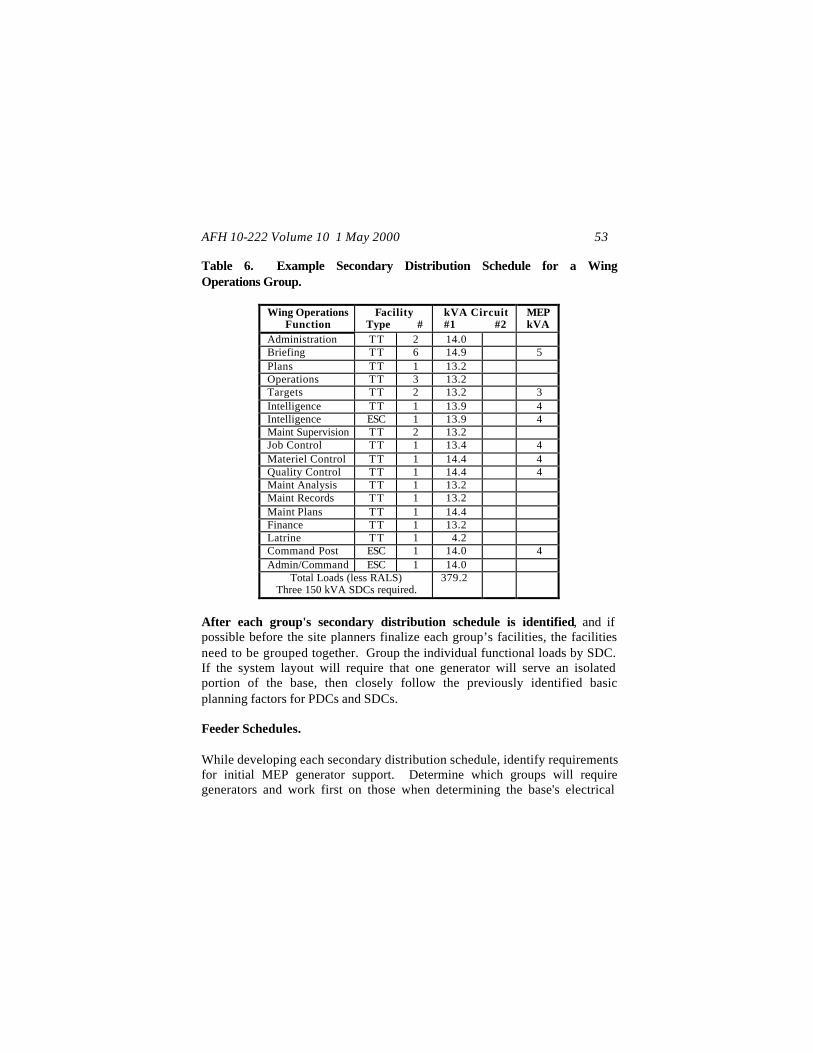
After the diversified loads are identified and excess loads split between circuits, the next step is to identify how many of each facility type will be included in each of the facility groups. This will allow development of a Secondary Distribution Schedule for each facility group. Example: Table 2 provided the breakout of facilities that are available in a 3,300-person bare base package. For this size package, a typical Wing Operations Group would be composed of 25 temper tents and 3 expandable shelter containers. These would normally be configured for specific functions as listed under Facility Group W – Wing Operations in Table 5. Based on the number of facilities and their function, a Secondary Distribution Schedule should be developed (Table 6) as a preliminary worksheet for checking on the specific number of functions and facilities to be served within a group. It is easy to use to brief commanders and control centers with and to determine if there are going to be any specific changes to organizations before going out to hard wire the base. Using this suggested format and the information from the previous tables, the third column under the heading shows the number of facilities of the same type that will be included within a specific group. The fourth and fifth columns under the heading shows the specific diversified loads, if any, required to service each facility. The sixth column under the heading shows the estimated basic MEP load required. The final line on this worksheet provides a preliminary total power demand, which is determined by multiplying the number of facilities for each function by the kVA load for each function and adding the products together. By dividing the results by the size of the SDC you will be using, such as a 150 kVA SDC, you can determine the preliminary number of SDCs that may be required to support the group.
AFH 10-222 Volume 10 1 May 2000 53
Table 6. Example Secondary Distribution Schedule for a Wing Operations Group.
Wing Operations Function
Facility Type #
kVA Circuit #1 #2
MEP kVA
Administration TT 2 14.0 Briefing TT 6 14.9 5 Plans TT 1 13.2 Operations TT 3 13.2 Targets TT 2 13.2 3 Intelligence TT 1 13.9 4 Intelligence ESC 1 13.9 4 Maint Supervision TT 2 13.2 Job Control TT 1 13.4 4 Materiel Control TT 1 14.4 4 Quality Control TT 1 14.4 4 Maint Analysis TT 1 13.2 Maint Records TT 1 13.2 Maint Plans TT 1 14.4 Finance TT 1 13.2 Latrine TT 1 4.2 Command Post ESC 1 14.0 4 Admin/Command ESC 1 14.0
Total Loads (less RALS) Three 150 kVA SDCs required.
379.2
After each group's secondary distribution schedule is identified, and if possible before the site planners finalize each group’s facilities, the facilities need to be grouped together. Group the individual functional loads by SDC. If the system layout will require that one generator will serve an isolated portion of the base, then closely follow the previously identified basic planning factors for PDCs and SDCs.
Feeder Schedules. While developing each secondary distribution schedule, identify requirements for initial MEP generator support. Determine which groups will require generators and work first on those when determining the base's electrical

AFH 10-222 Volume 10 1 May 2000 54
distribution schedule. Identify how many and what types of facilities will be included in each of the facility groups. Group like functions that require generator support such that the MEP generators are fully loaded. If the base layout allows, minimize the number of generators required for initial beddown. This will decrease the manpower required for maintenance and operational support while you bed down the rest of the base. Table 7 is an example of how a SDC Feeder Schedule is developed. The example is based on the secondary distribution schedule for a Wing Operations Group at a 3,300-person bare base. The schedule expands on the requirements of Table 6 and allows the development of circuit designations for layout of the system. This specific example shows that all circuits were kept within the (100% loading) of a 150 kVA SDC and ensured that similar facilities/functions with MEP requirements were grouped together on two SDCs. The 44 kVA MEP load for one SDC would be carried by a MEP-006. The other 16 kVA of MEP requirements for the other SDC would produce a very low load on a MEP-006 generator. Therefore, the facilities and the SDC should be sited near enough to another group of facilities so that both groups could also be fed from the same SDC/MEP generator.

AFH 10-222 Volume 10 1 May 2000 55
Table 7. Example SDC Feeder Schedule for a Wing Operations Group.
Facility Group
Circuit # Designation
Function
KVA
MEP
SDC-W1: Wing Operations 1 W1 Briefing Facility 14.9 5 2 W2 Briefing Facility 14.9 5 3 W3 Briefing Facility 14.9 5 4 W4 Briefing Facility 14.9 5 5 W5 Briefing Facility 14.9 5 6 W6 Briefing Facility 14.9 5 7 W7 Targets 13.2 3 8 W8 Targets 13.2 3 9 W9 Intel 13.9 4 10 W10 Intel 13.9 4 TOTAL kVA TOTAL MEP kVA - Use a 60 kW generator
143.6 44
SDC-W2: Wing Operations 1 W11 Job Control 13.4 4 2 W12 Material Control 14.4 4 3 W13 Quality Control 14.4 4 4 W14 Command Post 14.0 4 5 W15 Maint Supervision 13.2 6 W16 Maint Supervision 13.2 7 W17 Maint Analysis 13.2 8 W18 Maint Records 13.2 9 W19 Maint Plans 14.4 TOTAL kVA TOTAL MEP kVA Share MEP with another SDC grouping
123.4 16
SDC-W3: Wing Operations 1 W20 Administration 14.0 2 W21 Operations 13.2 3 W22 Plans 13.2 4 W23 Plans 13.2 5 W24 Plans 13.2 6 W25 Admin/Command 14.0 7 W26 Finance 13.2 8 W27 Administration 14.0 9 W28 Latrine 4.2 TOTAL kVA 112.2
TOTAL WING OPERATIONS GROUP kVAs 379.2 60

AFH 10-222 Volume 10 1 May 2000 56
The feeder schedule for each group should be used to develop a circuit schematic to list the required connections. While the surveyors are laying out the base for the rough layout of major groups of facilities, the circuit schematics can be annotated to show concerns for a specific layout. Identify the basic distances and locations for placement of SDCs next to the major facilities and the circuits requiring MEP generators for the initial operation of the bare base. Critical base facilities may have to operate from the smaller MEP generators, linked by SDCs, for up to two weeks while assets arrive and the main electrical distribution system is installed. The schematics can be used to show and explain how facilities are located in proximity to SDCs and MEP generators. They can also be used to flag the need for a generator at critical facilities where a load on a generator would be so low that it should be shared with critical facilities in another group – thus affecting the siting within two groups. Figure 32 depicts an example SDC Circuit for a Wing Operations Group at a 3,300- person bare base. Phase Balancing. To operate a power plant or generator effectively, the load on all three phases (i.e., the three contributing hot wires) of the system must be nearly equal. The difference between phases should not exceed 10 percent; otherwise, the generators will not be balanced and will not provide full output. Also, voltage regulation will be poor, which can damage both generating equipment and the equipment being operated. Even after all other load factors are known and system schematics determined, the system might require further analysis and balancing. This is especially true at critical or isolated facilities when smaller MEP generators are required for support.

AFH 10-222 Volume 10 1 May 2000 57
Figure 32. Example SDC Circuit for Wing Operations Group.
AFH 10-222 Volume 10 1 May 2000 58
When laying out and wiring for loads other than three-phase, take into account the total loading on each phase. Some equipment may be directly hard wired, but most equipment is connected through a PDP or facility service panel. Either way, try to balance the connections for each SDC circuit by balancing that circuit’s hot wire loads from the facilities. This may be as easy as making sure that numerous facilities on a circuit with 120-volt or 208-volt loads do not all use the same PDP circuit receptacles for the same hot wires (i.e., hot wire connections A, B, or C or A-B, A-C, or B-C). Radial versus Loop. Radial systems are normally planned for use during the initial stages of a deployment to support smaller deployments (i.e., 1,100-persons) when there is a very low threat. Otherwise, loop systems should be used, as they provide more reliable power, better system grounding, and greater flexibility for handling everyday type power demands and maintenance outages. The #1/0 aluminum, 5,000-volt primary cable and associated load break elbow connectors provide both adequate insulation and mechanical integrity when buried to the proper depth. They are used for interconnecting the power plants. The cable’s wrapped concentric neutral provides additional grounding capability and generally ensures that if weapons or equipment hit the cables, a short circuit will occur at the point of contact, blowing a fuse at the PDC and thus eliminating a lethal threat to personnel responding after an attack or to a repair. When deployed to higher threat beddown locations (where facility dispersal is required) and for larger deployments, especially for deployments supporting 2,200-persons or more, then power plant dispersal should be used. Dispersal for power plants does not mean that equipment and controls within the plant require greater separation distances. Protection of resources within the power plants should be through the use of revetments, barriers, concertina or barbed wire (entanglements), CCD, and berming. Power plant dispersal means having two or more plants (depending on the population and size of the installation) established and interconnected to ensure some degree of

AFH 10-222 Volume 10 1 May 2000 59
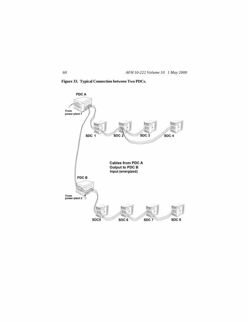
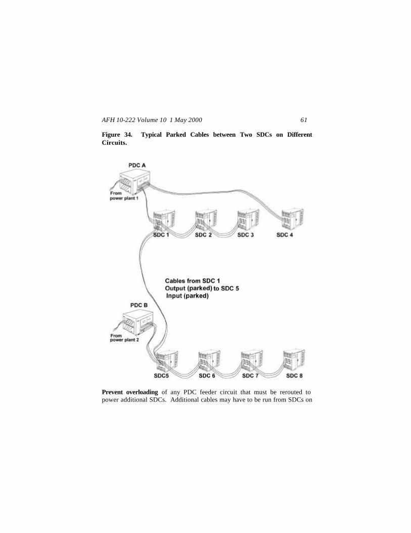
electrical generation capability is retained after an attack. For threat dispersal purposes, power plants should be located between 1,500 and 3,000 feet from each other as a part of a loop electrical distribution network. The primary method of looping is accomplished by interconnecting (in an energized status) between plants some of the PDCs at each plant. For PDC looping, physical connection is made from the output bushings of one PDC to the input bushings of another PDC (figure 33). In figure 33, PDC A has energized cables, which connect to the PDC B input side. Make sure that correct phasing is maintained and concentric grounds are properly connected. Larger beddowns may have two or three plants with more than one PDC. In this case, there are greater opportunities to loop between each separate plant and interconnect several PDCs to form a complete ring between three or more plants. NOTE: Unless an additional PDC is requested for the deployed location using UTC XFBEF, there will not be an adequate number of PDCs to allow looping or interconnecting of power plants. This is true for deployments of 1,100-person or greater packages. Plants can also be interconnected through SDCs on feeder circuits (figure 34) in an unenergized (parked) status. In the figure, PDC A feeds SDCs 1, 2, 3, and 4 while PDC B feeds SDCs 5, 6, 7, and 8. The unenergized cables from SDC 1 to SDC 5 are placed on parking stands for a set of output bushings on SDC 1 and placed on parking stands next to a set of input bushings on SDC 5. If the power plant serving PDC B or PDC B itself were put out of service, the PDC B system would have to be isolated. Then the cables at SDCs 1 and 5 are removed from the parking stands and placed on the respective output and input bushings to energize some of the SDCs served previously by PDC B. If PDC A were put out of service instead of PDC B, then the SDC output and input bushing connections would have to be reversed and placed on the respective output and input bushings for the two SDCs.
AFH 10-222 Volume 10 1 May 2000 60
Figure 33. Typical Connection between Two PDCs.
AFH 10-222 Volume 10 1 May 2000 61
Figure 34. Typical Parked Cables between Two SDCs on Different Circuits.
Prevent overloading of any PDC feeder circuit that must be rerouted to power additional SDCs. Additional cables may have to be run from SDCs on

AFH 10-222 Volume 10 1 May 2000 62
an operational PDC circuit (figure 35) to avoid overloads. Some of the SDC feeder circuits, which were previously on the inoperative PDC circuit, may also have to be rerouted. This would normally be done at the time of failure, but planning for alternate SDC to SDC connections should be considered when laying out the systems and utility corridors. Always ensure correct phasing is maintained, concentric grounds are connected properly, and the new circuits do not overload the PDC. Figure 35. Rerouting of Cables to Prevent Overloading of Remaining PDC.

AFH 10-222 Volume 10 1 May 2000 63
INSTALLATION The following are major installation processes. General Slope and Installation Limitations:
MEP-12A: The unit should be installed on a nearly level ground surface with a minimum slope for drainage, usually not to exceed 1%. PDC: The PDC is installed on a nearly level ground surface with a minimal slope to prevent the PDC from moving and to provide for adequate water drainage. The general ground slope near the PDC should not exceed 1% (i.e., 0.12 inches per foot or 1.2 inches in 10 feet). The preferred method of installation is to grade the area under the PDC to level and then grade the area around the PDC to slope away at 1% for drainage. It is basically a decision of the PDC operator and the climate as to where the 1-% slope for drainage needs to start -- either at the base of the PDC or 6 to 10 feet away. Ensure that the heavy equipment operator provides accurate grading. The slope away from the unit prevents standing water or ice from forming where the equipment is located and the operators are standing. The type of base material (i.e., does it hold water or is it free-flowing) and the amount of precipitation also influence the need for drainage. When performing switching operations, ensure that there is no standing water within the 10-foot clearance area. The PDC should be installed with no more than 1 degree of tilt (i.e., within 1 degree of level) (figure 36); 1° of equipment tilt is 0.209 inches per foot (i.e., 2.1 inches in 10 feet). If the unit shifts or settles after placement, then verify that it is still within 1° of level. If the unit settles, then the area under the unit should have fill added to bring the unit back to level.
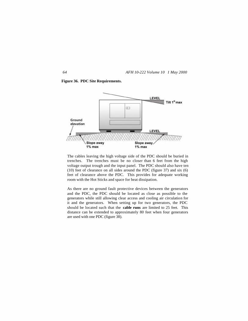
AFH 10-222 Volume 10 1 May 2000 64
Figure 36. PDC Site Requirements.
The cables leaving the high voltage side of the PDC should be buried in trenches. The trenches must be no closer than 6 feet from the high voltage output trough and the input panel. The PDC should also have ten (10) feet of clearance on all sides around the PDC (figure 37) and six (6) feet of clearance above the PDC. This provides for adequate working room with the Hot Sticks and space for heat dissipation.
As there are no ground fault protective devices between the generators and the PDC, the PDC should be located as close as possible to the generators while still allowing clear access and cooling air circulation for it and the generators. When setting up for two generators, the PDC should be located such that the cable runs are limited to 25 feet. This distance can be extended to approximately 80 feet when four generators are used with one PDC (figure 38).
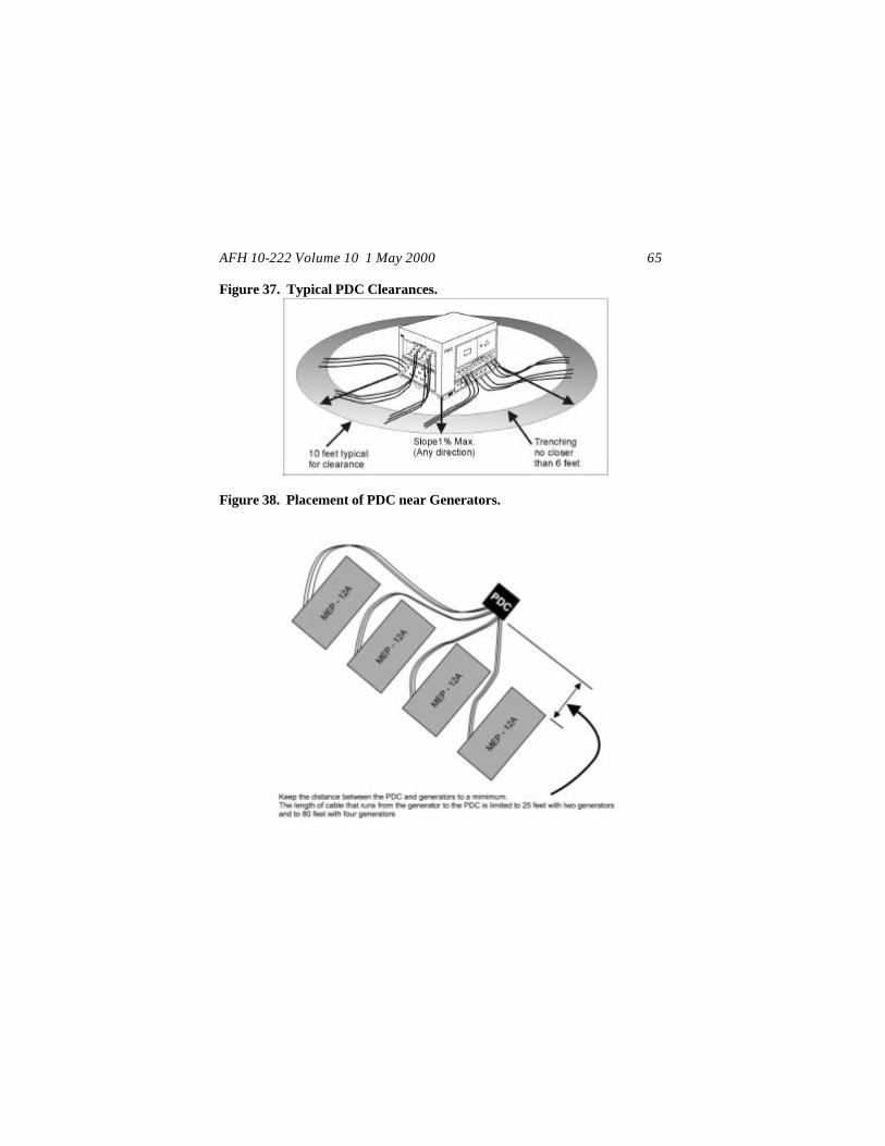
AFH 10-222 Volume 10 1 May 2000 65
Figure 37. Typical PDC Clearances.
Figure 38. Placement of PDC near Generators.

AFH 10-222 Volume 10 1 May 2000 66
SDC: The SDC should be installed on nearly level ground with enough slope surrounding the unit to allow for drainage; limit ground slope to about 1% unless faster drainage is required. Except that there is no criteria for tilt, the criteria for clearances and placement for the SDC should generally follow the criteria for the PDC. This will help ensure that the SDC’s high voltage input/transfer side is clear of standing water, operators have clearance for use of hot sticks, and that cables are similarly trenched for protection and safe operations.
Grounding Installed Equipment. Proper grounding of the Harvest Falcon electrical system is crucial for the safety of electrical and power production personnel. Procedures for grounding of this deployable system differ little from those used in standard electrical system installations. The grounding system for the Harvest Falcon electrical system equipment basically consists of equipment grounds with ground rods at major components and the (grounded) concentric neutral wires throughout the high voltage distribution portion of the system. While the applicable equipment technical orders describe specific grounding methods, the general requirements are as follows:
All equipment shall have a grounding resistance that does not exceed 25 ohms. Ground rods are driven as close as possible to the equipment grounding point for better continuity and to avoid creating a tripping hazard. The ground rods need only to extend above ground level about 6 inches to allow space for connection of the ground wire and then allow inspection and testing of the ground connection.
Note: Except where specified otherwise, equipment can be grounded with a #2 or #4 AWG copper wire. To avoid using too small a ground wire during a deployment, consider standardizing and using the largest specified ground size (i.e., #2 AWG copper) for grounding equipment to ground rods.
The MEP-12A is grounded at the front right (facing the tow bar) corner of the unit at the ground stud (figure 39). Connection to an equipment

AFH 10-222 Volume 10 1 May 2000 67
ground rod is made using either a #2 or #4 AWG copper wire. There is a second grounding lug on the MEP-12A located at the power panel, which is tied into the current transformer and ground fault relay. While it is possible to connect the ground rod and wire to this terminal, normal practice (to allow inspection and check of the ground connection) is to connect to the front ground stud. Both studs are bonded together with a grounding cable. Do not bond the ground rods of separate generators together and do not ground them to a central ground.
Figure 39. Ground Stud on MEP -12A Generator.
The PDC is grounded at two grounding lugs located opposite of each other at the bottom left of each output (load) side (figure 40). Connection to ground rods is commonly made using a #2 AWG copper wire. Drive the rods close to the grounding lugs to reduce tripping hazards. Bond the two ground rods together with additional copper wire.
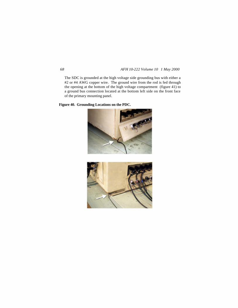
AFH 10-222 Volume 10 1 May 2000 68
The SDC is grounded at the high voltage side grounding bus with either a #2 or #4 AWG copper wire. The ground wire from the rod is fed through the opening at the bottom of the high voltage compartment (figure 41) to a ground bus connection located at the bottom left side on the front face of the primary mounting panel.
Figure 40. Grounding Locations on the PDC.

AFH 10-222 Volume 10 1 May 2000 69
Figure 41. Grounding Location on the SDC.
Ground rods and ground wire are provided with each unit of equipment. Ground rods are normally driven vertically at least 8 feet into the soil, as near to the equipment items as possible. Soil characteristics play a large part in the suitability of the grounding network. The type of soil, its chemical content, and the moisture level surrounding the ground rod will determine the resistance. Clay and loam soils with no rocks or stones will have a much lower resistance than clay or loam soils with many rocks or stones. Moisture content also affects resistance readings dramatically. As moisture content increases, soil resistivity decreases. This is especially true at the lower moisture content levels. Therefore, much of the dry, rocky, or sandy soils in SWA cannot provide the required soil resistivity of 25 ohms or less using just the driven ground rods provided with each unit. For good grounding you must have a ground rod that will be in contact with moist soil. Use as many ground rods as required to obtain adequate resistance readings. If deployed to a location where a ground rod cannot be
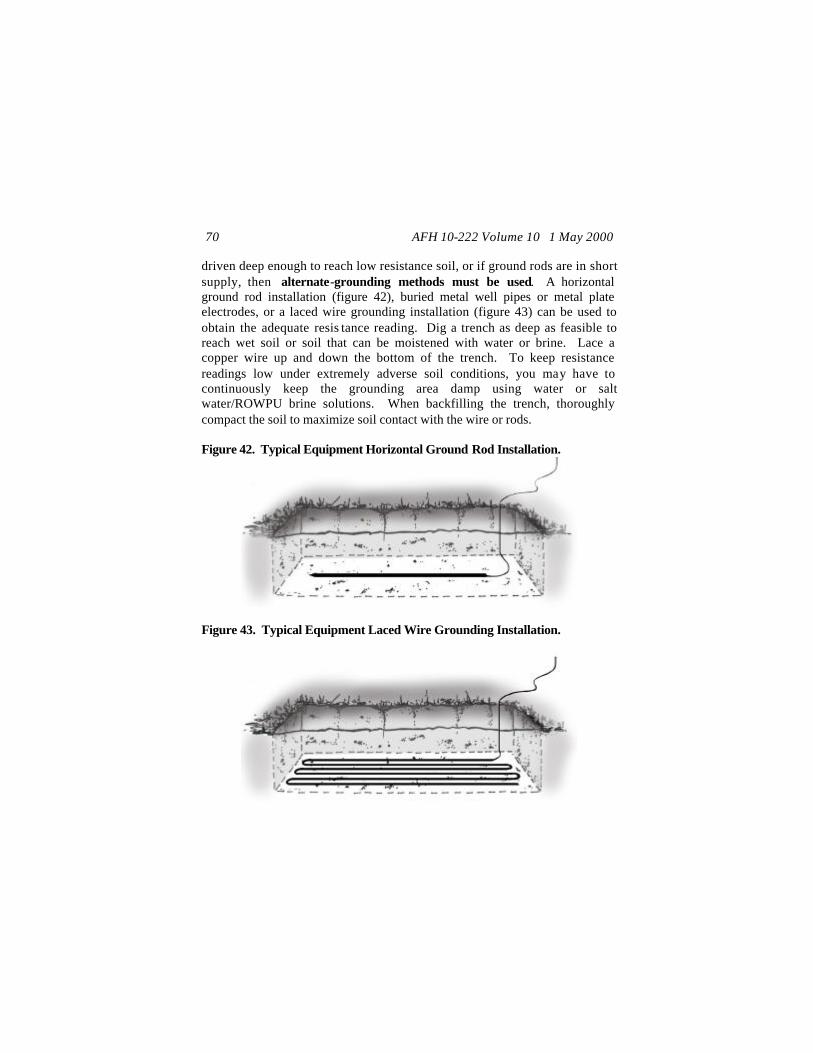
AFH 10-222 Volume 10 1 May 2000 70
driven deep enough to reach low resistance soil, or if ground rods are in short supply, then alternate-grounding methods must be used. A horizontal ground rod installation (figure 42), buried metal well pipes or metal plate electrodes, or a laced wire grounding installation (figure 43) can be used to obtain the adequate resis tance reading. Dig a trench as deep as feasible to reach wet soil or soil that can be moistened with water or brine. Lace a copper wire up and down the bottom of the trench. To keep resistance readings low under extremely adverse soil conditions, you may have to continuously keep the grounding area damp using water or salt water/ROWPU brine solutions. When backfilling the trench, thoroughly compact the soil to maximize soil contact with the wire or rods. Figure 42. Typical Equipment Horizontal Ground Rod Installation.
Figure 43. Typical Equipment Laced Wire Grounding Installation.
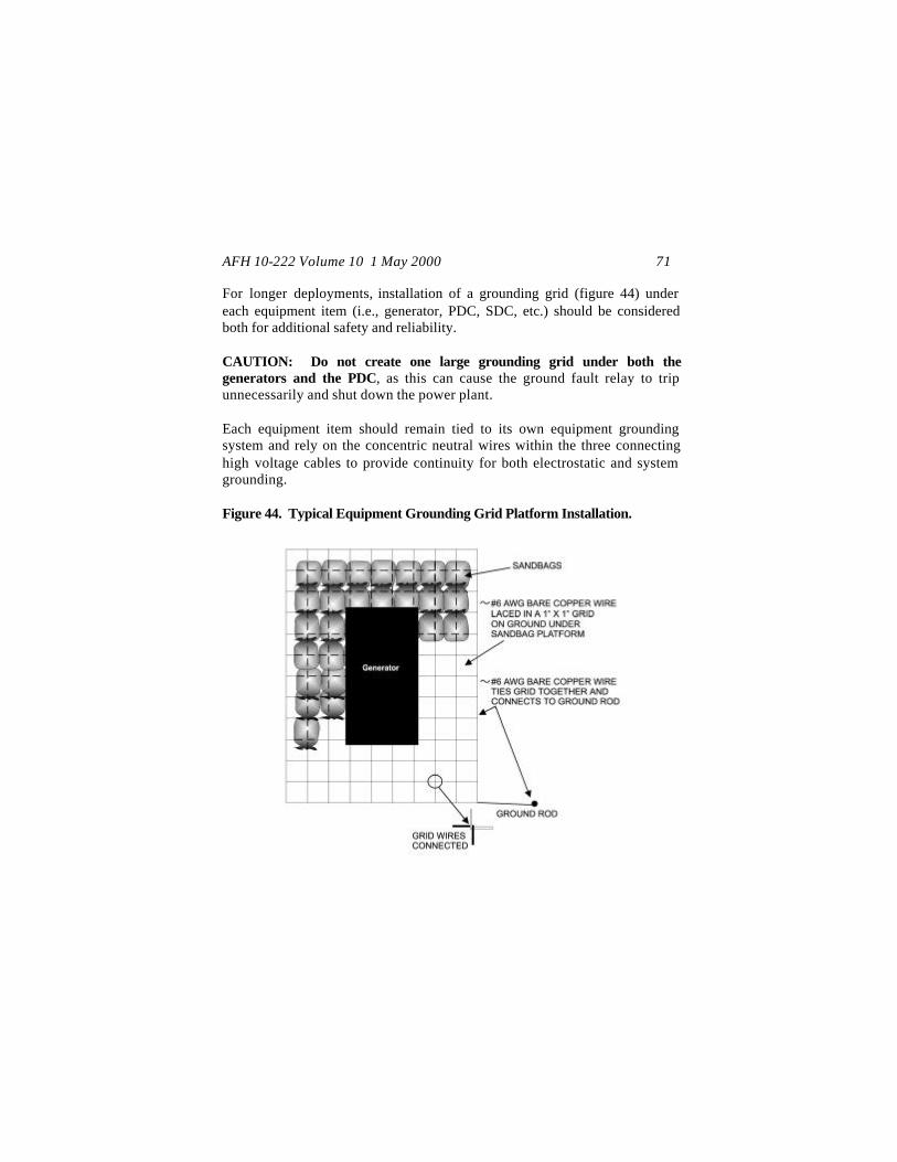
AFH 10-222 Volume 10 1 May 2000 71
For longer deployments, installation of a grounding grid (figure 44) under each equipment item (i.e., generator, PDC, SDC, etc.) should be considered both for additional safety and reliability. CAUTION: Do not create one large grounding grid under both the generators and the PDC, as this can cause the ground fault relay to trip unnecessarily and shut down the power plant. Each equipment item should remain tied to its own equipment grounding system and rely on the concentric neutral wires within the three connecting high voltage cables to provide continuity for both electrostatic and system grounding. Figure 44. Typical Equipment Grounding Grid Platform Installation.

AFH 10-222 Volume 10 1 May 2000 72
Be aware that the PDPs also have external ground lugs on their frames for grounding of the units. In desert locations, it may not be possible to provide an adequate ground for every small facility PDP due to the soil conditions. However, larger PDPs such as the 60 kW, 100 kW, and 200 kW units that serve as major distribution centers for large facilities, several facilities, or facilities with numerous major equipment items, must have a separate ground at each PDP. This is especially important in climate areas with high moisture levels. If deployed to a location in a climatic zone where freezing temperatures cause the ground to freeze, be sure to lay the horizontal grounding system below the frost line, as resistivity readings can increase substantially for frozen ground. Also, frost heaves that occur in soil with different moisture contents may cause equipment to tilt or move if the buried horizontal rod or wire system is located too close to the equipment. Keep the disturbed, moistened soil of the buried grounding system at least 10 feet from the supported equipment. The grounding system should normally be within 15 feet of the supported equipment; this is not a hard and fast rule and is dictated more by the available area and materials and the ability to obtain and maintain adequate resistance readings. For driven ground rods, recheck the resistance readings throughout the deployment. Trenching. During the initial layout and early operation, the Harvest Falcon electrical distribution network is an above ground system. When time permits, the primary distribution electrical lines are buried in trenches about 18-inches deep. The trenches should be wide enough to provide a 6-inch separation between cables. Cables should not be laid directly on sharp rocks or in very rocky soil; where such rocks are present, place a layer of sand or other soil free of sharp rocks on the bottom of the trench. If the soil is very rocky and the area will be trafficked, then a layer of sand or rock free soil may be also be required above the cables.
AFH 10-222 Volume 10 1 May 2000 73
At locations where cables cross roadways and in power plants after equipment has been located, the lines should be buried even in the initial phases of the operation. Consideration should be given to running the lines in conduit under roadways and burying the cables deeper to allow improving roads over these cables with gravel or hard surface. Secondary distribution lines for service from SDCs should also be buried (when time permits) in shallower trenches. Under most climactic conditions, secondary distribution lines require only 8 inches of cover. Exceptions:
For desert conditions, heat will degrade both primary and secondary cable; ensure that the cable has at least 12 to 16 inches of cover. In areas subject to ground freezing, the cable should be buried below the frost line. In locations which may experience numerous freeze-thaw cycles throughout the winter (where there is intermittent flooding and ground movement), buried cannon plug cable connections may require some waterproofing protection (i.e., wrap in plastic sheeting and tape) or be surrounded with free draining sandy gravel. If winterizing procedures are required for the deployment, marking or otherwise identifying buried cannon plug connections at critical facilities will allow them to be checked if freeze-thaw cycles cause problems with electrical connections.
Most trenching is accomplished using a tractor with backhoe and blade. The attachments are removable and/or interchangeable. Upon arrival at the deployment location, the Civil Engineer’s tractor may arrive configured with or without a rotary-trenching wheel (figure 45), which is normally associated with Communication’s configuration of the tractor. The equipment is associated with the Harvest Eagle equipment UTC and must be identified that way. If the equipment arrives with the rotary-trencher, the rotary-trencher may be removed or used by Civil Engineers for burying secondary or primary distribution cables. Expect to have some handwork when burying cable near generators, PDCs, and SDCs.

AFH 10-222 Volume 10 1 May 2000 74
Figure 45. Tractor with Backhoe, Blade, and Trenching Wheel.
Especially for facilities that require more reliable power and for interconnecting power plants, it is necessary to maintain the 6-inch separation (figure 46) for primary power cables and to keep the cable from bundling together in the trench. If a rotary-trencher is used, maintaining adequate separation will be difficult due to the narrow width of the trench. Field conditions may dictate various installation choices, which can be used to maintain a 6-inch separation and also meet required cover and protection, such as:
Multiple trenches with a wheel cutter trencher, Wider trenches, and/or Deeper trenches and cable laid with horizontal and a vertical separation between cables.
In the immediate power plant area, make sure the trenches are clearly marked to ensure that future additional trenching operations will not hit buried power cables. Plan ahead, especially when multiple power plants are used, to provide access for routing of cables between plants. In some cases it may be
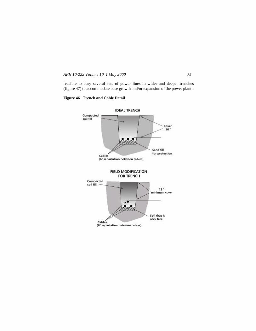
AFH 10-222 Volume 10 1 May 2000 75
feasible to bury several sets of power lines in wider and deeper trenches (figure 47) to accommodate base growth and/or expansion of the power plant. Figure 46. Trench and Cable Detail.

AFH 10-222 Volume 10 1 May 2000 76
Figure 47. Multiple Cable Runs in Common Trench.
Keep accurate, up-to-date records on the location of power lines and when possible, mark the cable routes. Cable routes between plants can be relatively long, traversing much of the camp area. During long-term deployments, trenches can become overgrown or covered by blowing sand. If they do not have accurate records, follow-on units can easily disrupt electrical and other utilities when trenching to expand or repair/replace systems. Fabrication for Load Break Elbows. Cables are cut to length in the field and load break elbows are used as connections. Load break elbow assemblies vary based on the model used. See Attachment 4 for general instructions; follow the appropriate technical orders or the manufacturer’s specific instructions if available. Connection from Generators to PDCs. After laying out and locating equipment for the power plant(s), fabricate all three phases of cable connections between the 750 kW generators and the PDCs. Ensure that 3 to 4 feet of the concentric ground wire are available for

AFH 10-222 Volume 10 1 May 2000 77
each cable. Connect the primary cables to the generator by first attaching each cable’s concentric ground wire to the grounding point on the chassis of the generator. Use the Grip-All clamp stick to make all physical connections of the primary cables to the generator’s bushing well inserts. After removing the red dust caps from the bushings, position a load break elbow over one of the bushing well inserts and push it into place. Be sure that the elbow is completely seated. This process will need to be repeated for all three phases. Repeat this process for each generator that is to be connected to the PDC. After the primary cables have been connected to the generators, park the cables on the line side of the PDC until cables are run from the PDCs to the SDCs and you are ready to energize a circuit. Before physically connecting the cables to the PDC bushing well inserts, connect all the concentric ground wires from each cable to the grounding lugs across from each connection point. Then connect the cables to the bushings (figure 48) using the Grip-All clamp stick. Install high voltage terminal caps on all the line side bushing well inserts that are not being used for generator connections. Any bushing well insert not being used on the line side is energized because they are connected to a commo n bus bar. When making high voltage cable connections, work with the equipment in an unenergized state. After establishing the power plant layout for the generators and PDC, trench and bury the cables.
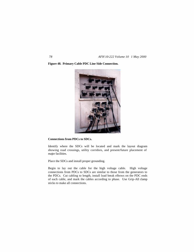
AFH 10-222 Volume 10 1 May 2000 78
Figure 48. Primary Cable PDC Line Side Connection.
Connections from PDCs to SDCs. Identify where the SDCs will be located and mark the layout diagram showing road crossings, utility corridors, and present/future placement of major facilities. Place the SDCs and install proper grounding. Begin to lay out the cable for the high voltage cable. High voltage connections from PDCs to SDCs are similar to those from the generators to the PDCs. Cut cabling to length, install load break elbows on the PDC ends of each cable, and mark the cables according to phase. Use Grip-All clamp sticks to make all connections.
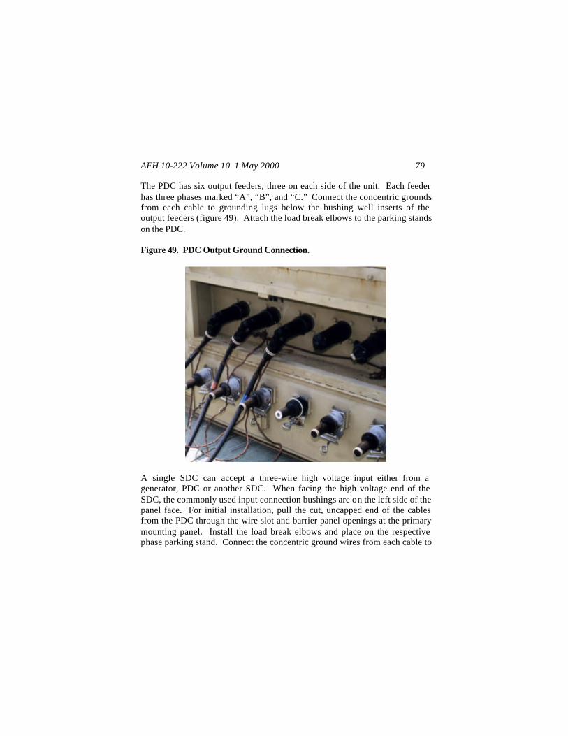
AFH 10-222 Volume 10 1 May 2000 79
The PDC has six output feeders, three on each side of the unit. Each feeder has three phases marked “A”, “B”, and “C.” Connect the concentric grounds from each cable to grounding lugs below the bushing well inserts of the output feeders (figure 49). Attach the load break elbows to the parking stands on the PDC. Figure 49. PDC Output Ground Connection.
A single SDC can accept a three-wire high voltage input either from a generator, PDC or another SDC. When facing the high voltage end of the SDC, the commonly used input connection bushings are on the left side of the panel face. For initial installation, pull the cut, uncapped end of the cables from the PDC through the wire slot and barrier panel openings at the primary mounting panel. Install the load break elbows and place on the respective phase parking stand. Connect the concentric ground wires from each cable to
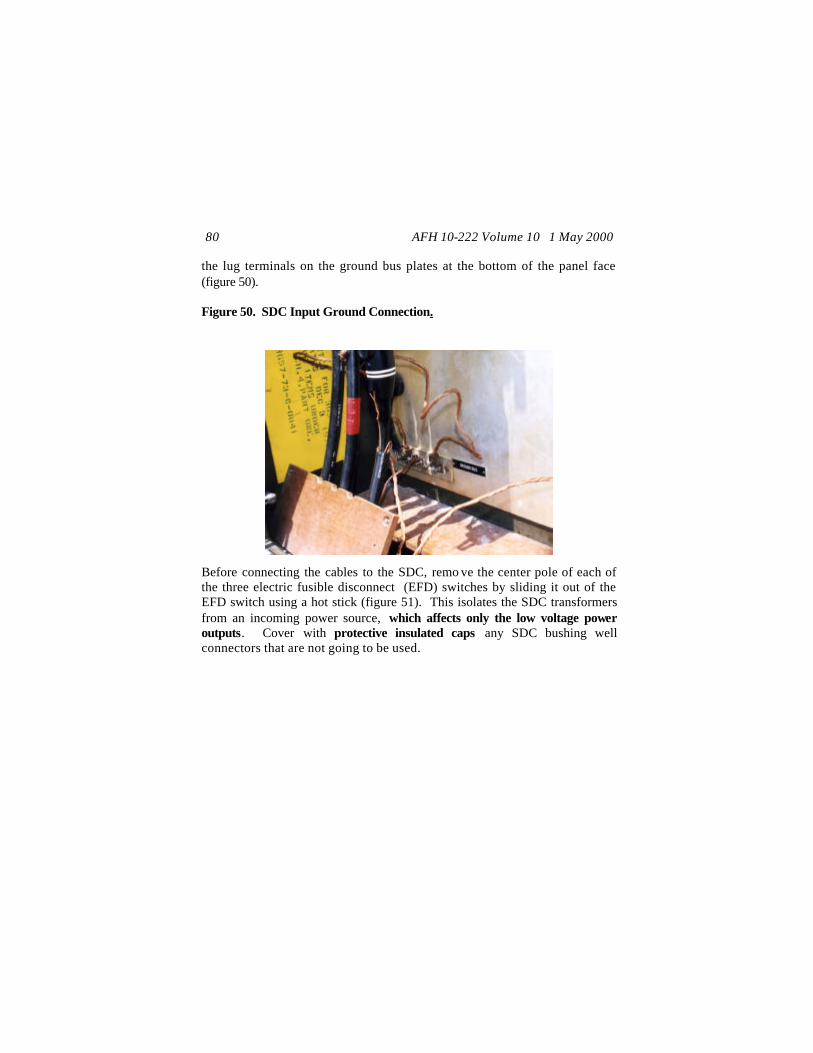
AFH 10-222 Volume 10 1 May 2000 80
the lug terminals on the ground bus plates at the bottom of the panel face (figure 50). Figure 50. SDC Input Ground Connection.
Before connecting the cables to the SDC, remo ve the center pole of each of the three electric fusible disconnect (EFD) switches by sliding it out of the EFD switch using a hot stick (figure 51). This isolates the SDC transformers from an incoming power source, which affects only the low voltage power outputs. Cover with protective insulated caps any SDC bushing well connectors that are not going to be used.
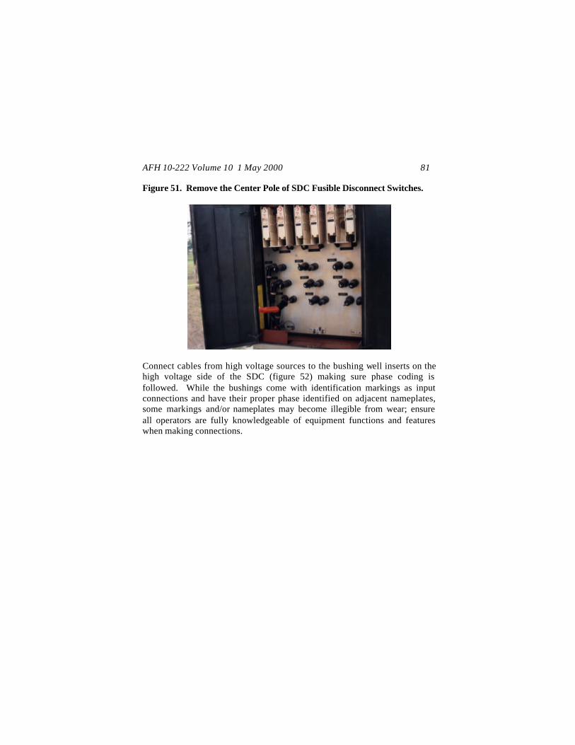
AFH 10-222 Volume 10 1 May 2000 81
Figure 51. Remove the Center Pole of SDC Fusible Disconnect Switches.
Connect cables from high voltage sources to the bushing well inserts on the high voltage side of the SDC (figure 52) making sure phase coding is followed. While the bushings come with identification markings as input connections and have their proper phase identified on adjacent nameplates, some markings and/or nameplates may become illegible from wear; ensure all operators are fully knowledgeable of equipment functions and features when making connections.
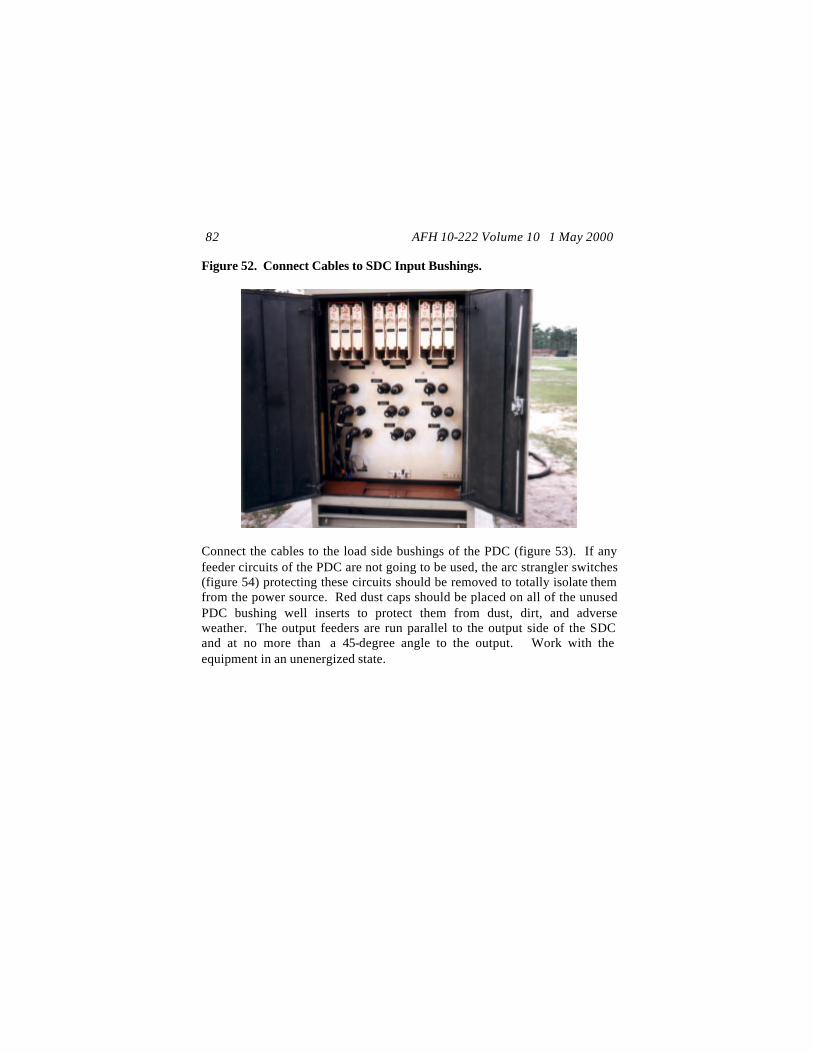
AFH 10-222 Volume 10 1 May 2000 82
Figure 52. Connect Cables to SDC Input Bushings.
Connect the cables to the load side bushings of the PDC (figure 53). If any feeder circuits of the PDC are not going to be used, the arc strangler switches (figure 54) protecting these circuits should be removed to totally isolate them from the power source. Red dust caps should be placed on all of the unused PDC bushing well inserts to protect them from dust, dirt, and adverse weather. The output feeders are run parallel to the output side of the SDC and at no more than a 45-degree angle to the output. Work with the equipment in an unenergized state.
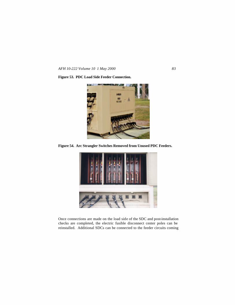
AFH 10-222 Volume 10 1 May 2000 83
Figure 53. PDC Load Side Feeder Connection.
Figure 54. Arc Strangler Switches Removed from Unused PDC Feeders.
Once connections are made on the load side of the SDC and post-installation checks are completed, the electric fusible disconnect center poles can be reinstalled. Additional SDCs can be connected to the feeder circuits coming

AFH 10-222 Volume 10 1 May 2000 84
from two sets of bushing well inserts on the line side panel face of an SDC. The output terminals (figure 55) are connected from these bushings to other SDC input bushings. Work with the equipment in an unenergized state. Figure 55. Input and Output Cables on a SDC.
Make sure proper phase order is maintained for all equipment connections in the system and concentric ground wires are connected at both ends of all PDC-to-SDC and SDC-to-SDC cabling. After the SDCs have been installed on a PDC circuit, the system circuit can be energized. Connections from SDCs to PDPs and Service Panels. Individual feeder circuits from the SDCs are run from feeder receptacles (using cannon plugs) along 50-foot and 100-foot cables. They connect to either facility power distribution panels (PDPs) (figure 56), shelter electrical service panels (figure 57), or specific equipment items with compatible cannon plug connections (example, ECUs and RALs). Power may also be run to an ECU from the served PDP (figure 58) or shelter electrical service panel.

AFH 10-222 Volume 10 1 May 2000 85
Figure 56. Cannon Plug Connection from SDC to Small Shelter System PDP.
Figure 57. Cannon Plug Connection from SDC to ESC Service Panel.
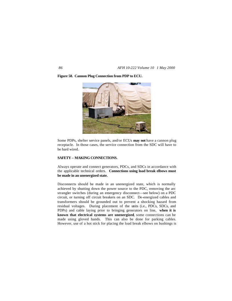
AFH 10-222 Volume 10 1 May 2000 86
Figure 58. Cannon Plug Connection from PDP to ECU.
Some PDPs, shelter service panels, and/or ECUs may not have a cannon plug receptacle. In those cases, the service connection from the SDC will have to be hard wired. SAFETY – MAKING CONNECTIONS. Always operate and connect generators, PDCs, and SDCs in accordance with the applicable technical orders. Connections using load break elbows must be made in an unenergized state. Disconnects should be made in an unenergized state, which is normally achieved by shutting down the power source to the PDC, removing the arc strangler switches (during an emergency disconnect—see below) on a PDC circuit, or turning off circuit breakers on an SDC. De-energized cables and transformers should be grounded out to prevent a shocking hazard from residual voltages. During placement of the units (i.e., PDCs, SDCs, and PDPs) and cable laying prior to bringing generators on line, when it is known that electrical systems are unenergized, some connections can be made using gloved hands. This can also be done for parking cables. However, use of a hot stick for placing the load break elbows on bushings is

AFH 10-222 Volume 10 1 May 2000 87
always a good safety practice to ensure proper seating of the load break elbows. Safety and electrical equipment should be used when connecting and disconnecting load break elbows, arc strangler switches, and fusible switches. The following common safety procedures should be used when making connects and disconnects for specific components. MEP-12A Generator Connections: Use the Grip-All Clamp Stick or the Load Break Elbow Stick to connect and disconnect load break elbows (figure 59). Do not use Switch Sticks, as these will cause damage to load break elbows. Only trained personnel should perform connect and disconnect operations. Figure 59. Use of Grip-All Clamp Stick for Connecting to Generator.
AFH 10-222 Volume 10 1 May 2000 88
Verify that cabling at and between the generator and the load is in serviceable condition, protected from vehicle traffic or other possible sources of damage, and that the cable phasing is maintained. PDC Connections: The primary (line side) and the secondary (output side) cables are high voltage power distribution cables and are connected using a Grip-All Clamp Stick with the load break elbows. The arc strangler switches are connected and disconnected using Switch Stick type hot sticks. Always ensure that proper phasing is maintained for all cable connections. Before the PDC is energized, use a Switch Stick to check all arc strangler disconnect switches. Install cables with load break elbows on the line side and load side bushings. Connect each cable’s concentric ground to the proper grounding location on the PDC. CAUTION: Insulated gloves are not required for use with properly cared for and maintained switch sticks. If the switch stick is beginning to break down, then there should be a tingling sensation felt in the hands during an energized connection or disconnect, such as to arc strangler switches. If the stick is beginning to break down, the stick should be removed from service. If insulated gloves were worn, then a failing stick may not be detected early on and the stick could inadvertently be used when it should have been replaced. Emergency Energized Disconnect: If during installation or operation a problem occurs and an emergency energized disconnect of an output circuit is required, disconnect using the arc strangler switches -- not the load break elbows . The following procedures should be used:
Two qualified electrical personnel with safety and electrical equipment must be available to disconnect (isolate) the circuit. Use rubber gloves to open doors and remove lexan barriers . Make sure that the hole in the arc strangler switch shaft is not exposed. If it is visible, then the circuit must be de-energized; do not attempt an emergency disconnect.

AFH 10-222 Volume 10 1 May 2000 89
The two electrical personnel with Switch Sticks, one designated to handle Phase A and the other Phase C, position themselves at a 90-degree angle to the fuses. While holding (without insulated gloves) the far end of the Switch Sticks, engage the Switch Stick into the pull rings of the two outside arc strangler switches (Phases A and C) (figure 60).
Figure 60. Proper Set-up for Disconnecting the Arc Strangler Switches.
On the command of “OPEN” by the electrical person pulling Phase A, both personnel pull the switch blades open at the same time. The Phase A person then immediately goes back and pulls the arc strangler switch for Phase B. Only one person then removes all three arc strangler switches from the mounting brackets.

AFH 10-222 Volume 10 1 May 2000 90
If the system must then be re-energized during the emergency, reverse the above procedures for installing and throwing switches. Check to ensure that SDC individual circuit breakers for facilities and PDPs are off prior to reconnecting the PDC; this will prevent surging. Make sure that each switch blade engages and that at least half of the hole on the front of the switch blade shaft is covered by the arc strangler sleeve (i.e., the hole is no longer exposed).
SDC Connections: The secondary cables for high voltage power to a SDC are connected with load break elbows. This is always the case whether the cables are coming from a PDC, a MEP-12A generator, or from another SDC. Load break elbows are connected and disconnected using a Grip-All Clamp Stick. Disconnects must be made in an unenergized state. The input side of the SDC has three switches, each of which has three poles; each center pole is an EFD switch (figure 61). With each center poll removed, the SDC will not provide power to the low voltage output circuits, but will still transfer (through the high voltage bus) high voltage power to any other SDCs connected through the output bushings. When laying out and connecting the system, the EFD center poles for each SDC should be removed until all the individual SDC circuits are to be energized. The center poles are connected/disconnected with a Switch Stick (figure 62). The outer poles may also be removed, but must be reinstalled before the system is energized. Do not attempt to make an energized connection of the outer poles.
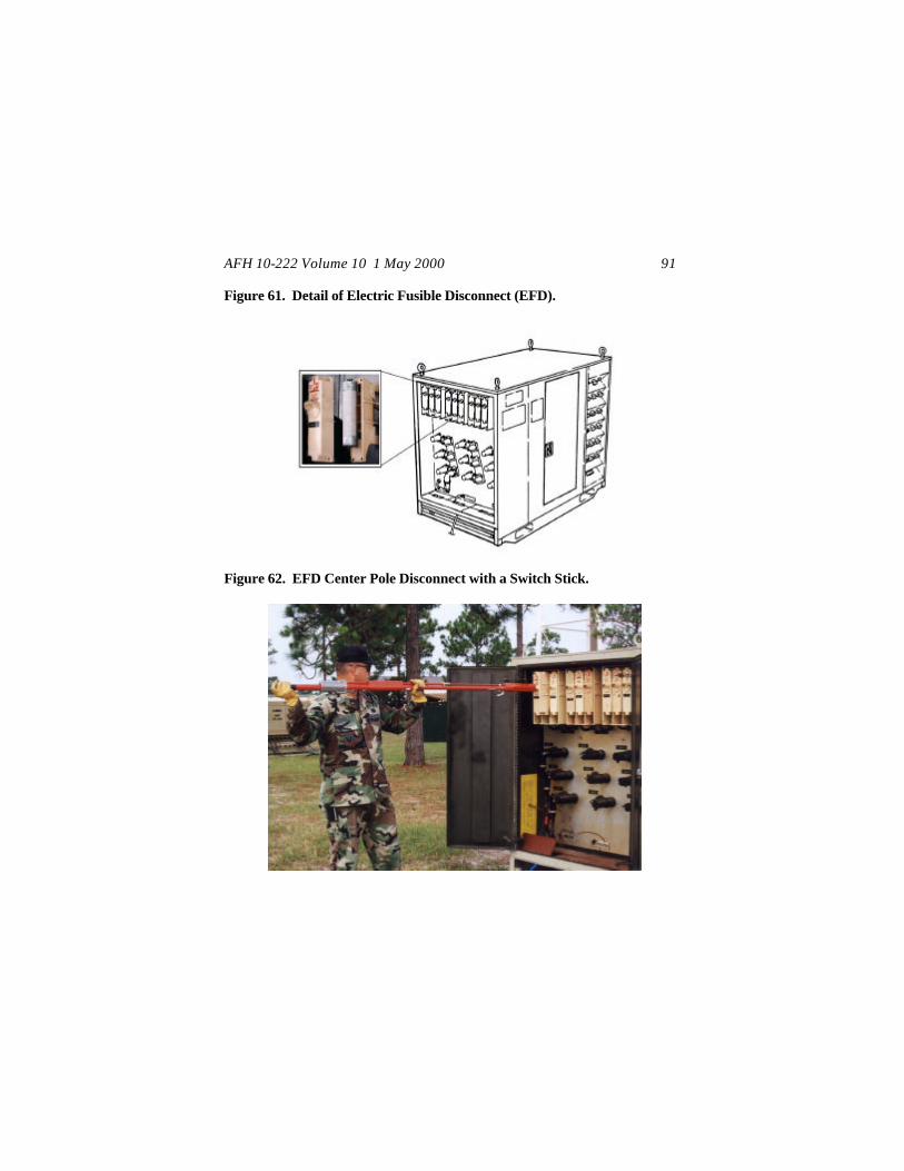
AFH 10-222 Volume 10 1 May 2000 91
Figure 61. Detail of Electric Fusible Disconnect (EFD).
Figure 62. EFD Center Pole Disconnect with a Switch Stick.
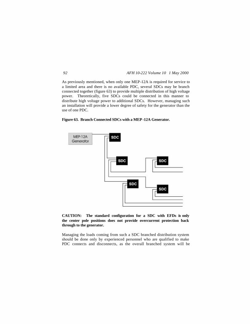
AFH 10-222 Volume 10 1 May 2000 92
As previously mentioned, when only one MEP-12A is required for service to a limited area and there is no available PDC, several SDCs may be branch connected together (figure 63) to provide multiple distribution of high voltage power. Theoretically, five SDCs could be connected in this manner to distribute high voltage power to additional SDCs. However, managing such an installation will provide a lower degree of safety for the generator than the use of one PDC. Figure 63. Branch Connected SDCs with a MEP -12A Generator.
CAUTION: The standard configuration for a SDC with EFDs in only the center pole positions does not provide overcurrent protection back through to the generator. Managing the loads coming from such a SDC branched distribution system should be done only by experienced personnel who are qualified to make PDC connects and disconnects, as the overall branched system will be

AFH 10-222 Volume 10 1 May 2000 93
functioning as a PDC. Unlike the PDC, which has fuses and disconnect switches, the SDC has only outer switch poles, which can be removed. However, there is no recommended procedure to allow high voltage, emergency energized disconnects for the SDC. This secondary (load) system is intended to be de-energized before pulling the outer poles with a hot stick. PDP Type Connections: The secondary cables for low voltage power are connected with military-type cannon plug connections to the PDPs. If the larger PDPs are connected to a smaller MEP generator, which must be hard wired, then the larger PDPs may also have to be hard wired. Check the manufacturer’s model and TO for any safety cautions or warnings that may be applicable for the unit. The secondary cables for low voltage power from the PDPs are connected with NEMA type twist-lock plugs to individual facility distribution and lighting strips. Do not make an energized low voltage connection with cannon plugs when connecting a cable to a SDC, a cable to a cable, or a cable to a PDP or a facility service panel connection. Before making a connection, the power to the cables should be turned off at the individual branch circuit breakers of the SDC. Check to ensure that individual circuit breakers for facilities and PDPs are also off during connections from SDCs to PDPs or facility panels. This will prevent surging on a circuit, and will also allow checking to ensure that if there is a problem with any one circuit coming out of a service type panel, then that problem can be more quickly identified.
Michael E. Zettler, Lt General, USAF DCS/Installations & Logistics
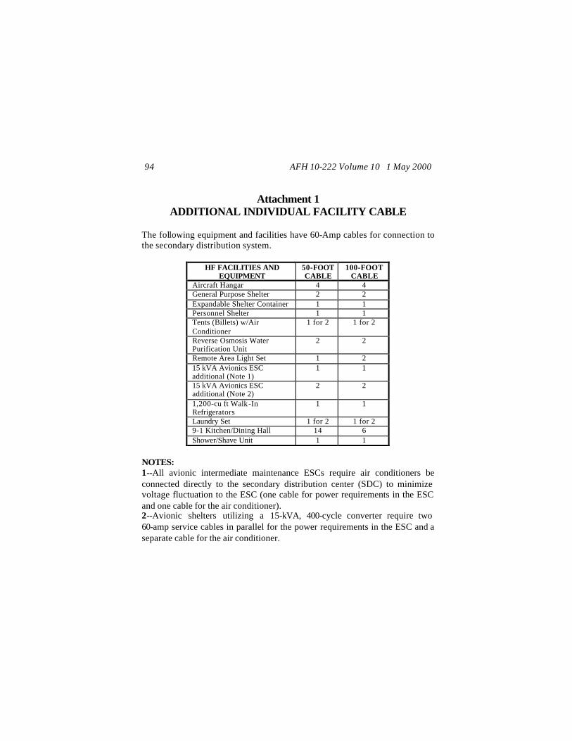
AFH 10-222 Volume 10 1 May 2000 94
Attachment 1
ADDITIONAL INDIVIDUAL FACILITY CABLE The following equipment and facilities have 60-Amp cables for connection to the secondary distribution system.
HF FACILITIES AND EQUIPMENT
50-FOOT CABLE
100-FOOT CABLE
Aircraft Hangar 4 4 General Purpose Shelter 2 2 Expandable Shelter Container 1 1 Personnel Shelter 1 1 Tents (Billets) w/Air Conditioner
1 for 2 1 for 2
Reverse Osmosis Water Purification Unit
2 2
Remote Area Light Set 1 2 15 kVA Avionics ESC additional (Note 1)
1 1
15 kVA Avionics ESC additional (Note 2)
2 2
1,200-cu ft Walk-In Refrigerators
1 1
Laundry Set 1 for 2 1 for 2 9-1 Kitchen/Dining Hall 14 6 Shower/Shave Unit 1 1
NOTES: 1--All avionic intermediate maintenance ESCs require air conditioners be connected directly to the secondary distribution center (SDC) to minimize voltage fluctuation to the ESC (one cable for power requirements in the ESC and one cable for the air conditioner). 2--Avionic shelters utilizing a 15-kVA, 400-cycle converter require two 60-amp service cables in parallel for the power requirements in the ESC and a separate cable for the air conditioner.

AFH 10-222 Volume 10 1 May 2000 95
Note: Specific numbers of assets with the Harvest Falcon UTCs may cause variations in the above table. Always confirm what the final configuration of assets will be for your deployment.
AFH 10-222 Volume 10 1 May 2000 96
Attachment 2
TYPICAL LAYOUT REQUIREMENTS FOR POWER PLANTS
The normal procedure is to orient the MEP-12A generator with the prevailing wind, such that the radiator-end of the unit is downwind. However, in extremely dusty climates, the units can be oriented with the radiators toward the prevailing winds to allow the radiator fan exhaust to blow the drifting dust away from the radiators (figure A2.1). The generators must have a minimum clearance of 5 feet between units. They may be spaced wider apart to allow for additional cooling, especially if the prevailing winds have a range of directions. Up to 20 feet is used to allow for a range of wind directions. However, the wider the units are spaced, the harder it is too keep them within 80 feet of the PDC. Provide at least a 2-foot clearance around the empty bladder as it is being laid out (figure A2.2); the clearance area should be level. The area under the filled bladder should have an even 1° slope from the edges of the bladder to the area under the bladder’s vent pipe (i.e., about a 5-inch drop). This slope will allow condensation to collect for removal through the vent pipe. The berm should provide for containment of fuels and protection from threat. The minimum fuels containment criteria for the berm are: the berm height is a minimum of 3.5 feet higher than the bottom of the bladder and the enclosed volume must be a minimum of 1.5 times the volume of the bladder. After meeting these criteria, you should increase the berm height as necessary to prevent entry by terrorist vehicles or to stop fragmentation from indirect-fired weapons, such as rockets, grenades, and mortars. With the approval of fire protection and fuels personnel for berms inclosing two or more bladders, the intermediate berm walls between bladders may be eliminated. The elevation at the bottom of the fuel tanks may be even with the existing ground level or semi-depressed (i.e., the bottom of the berm is
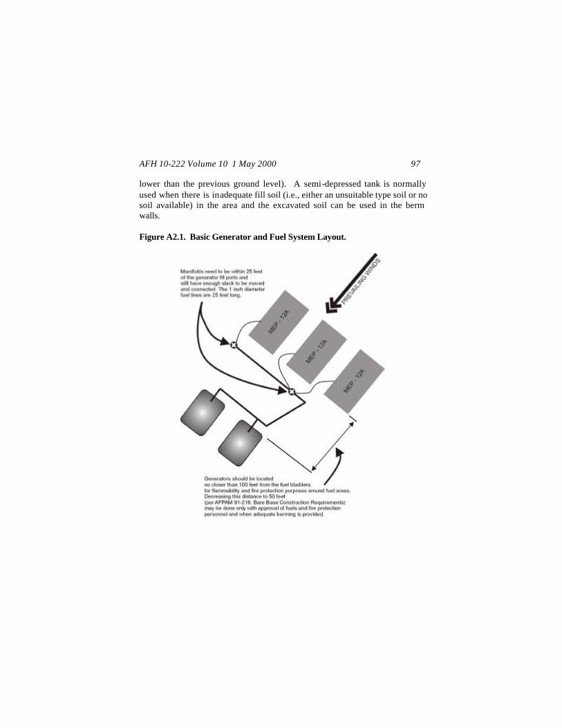
AFH 10-222 Volume 10 1 May 2000 97
lower than the previous ground level). A semi-depressed tank is normally used when there is inadequate fill soil (i.e., either an unsuitable type soil or no soil available) in the area and the excavated soil can be used in the berm walls. Figure A2.1. Basic Generator and Fuel System Layout.
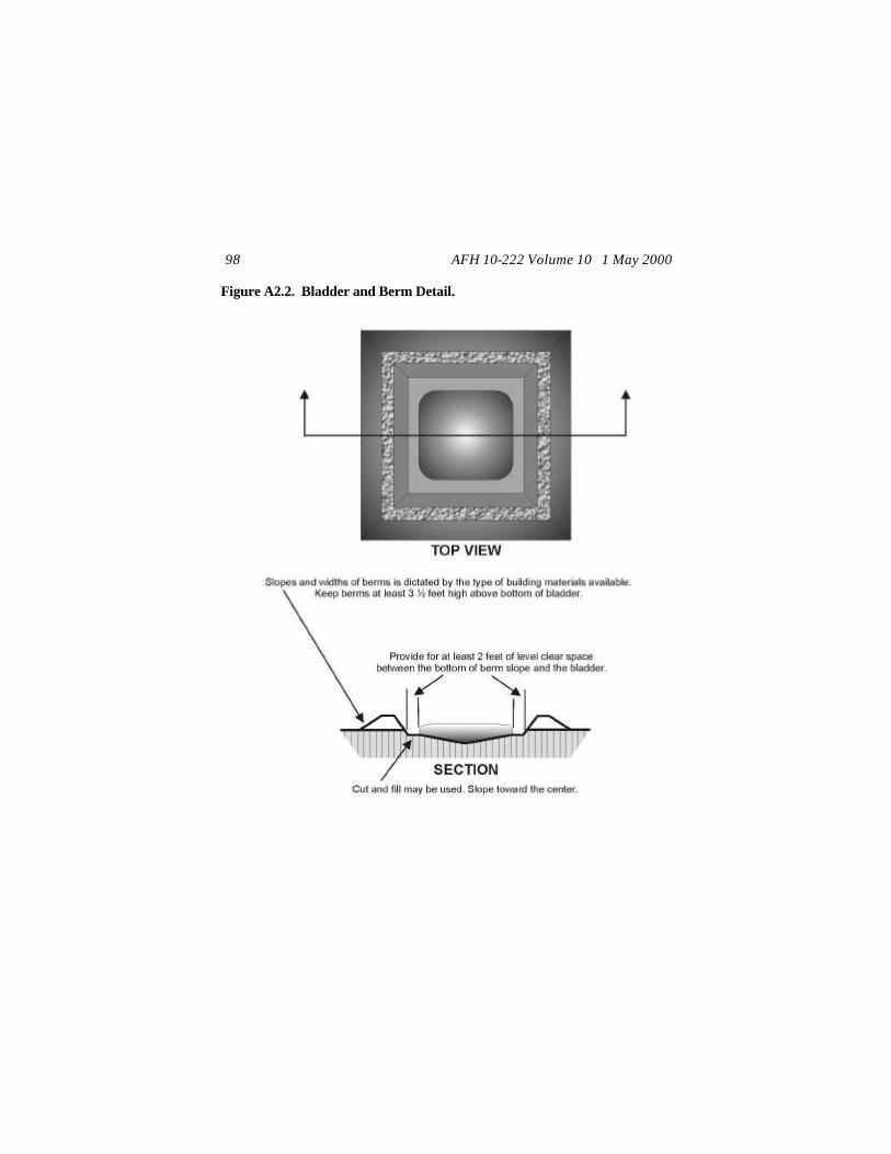
AFH 10-222 Volume 10 1 May 2000 98
Figure A2.2. Bladder and Berm Detail.
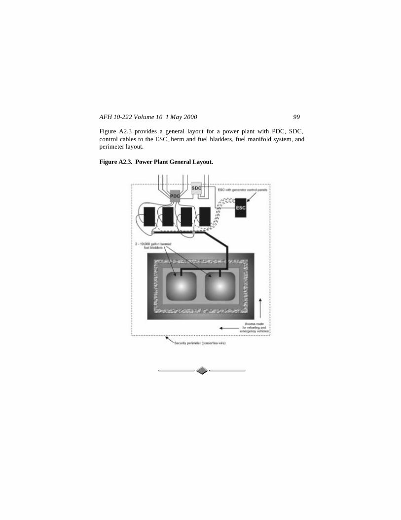
AFH 10-222 Volume 10 1 May 2000 99
Figure A2.3 provides a general layout for a power plant with PDC, SDC, control cables to the ESC, berm and fuel bladders, fuel manifold system, and perimeter layout. Figure A2.3. Power Plant General Layout.

AFH 10-222 Volume 10 1 May 2000 100
Attachment 3
SPECIFIC FACILITY MATRIX
FUNCTION
ASSET TYPE
BASE POPULATION 1100 2200 3300
Administration Billeting Briefing Facilities Kitchen/Dining Hall (9-1) Mobile Kitchen Trailer Shower/Shave Facility Latrine Laundry Mortuary General Purpose Facility Power Pro Facility Multipurpose Facility Common Facility Chaplain Tactical Field Exchange Tactical Field Exchange Combat Supply Combat Supply Modular Structure 8000SF Modular Structure 4000SF Vehicle Maint. 4000SF Pack/Crate 8000SF Aircrew Alert Facility Fire Operations Fuels Lab CE Eng. Management CE Utilities CE Material Management CE Electric Shop CE Structures Shop CE Liquid Fuels Shop CE HVAC Shop CE Pest Management Shop
TT TT TT TT SET MKT TT TT TT TT GP ESC TT ESC TT ESC TT ESC FSTFS 1 FSTFS 1 FSTFS 1 FSTFS 1 FSTFS 1 TT TT ESC TT TT TT TT TT TT TT TT
20 94
2 1 2 5
14 2 2
14 1 4 8 1 2 2 2 1 4 2 2 1 3 3 1 2 3 1 1 1 1 1 1
36 188
4 2 2
10 22
4 3
15 2 4 8 1 2 2 2 1 4 2 2 1 3 3 1 2 5 1 1 1 1 1 1
52 282
6 3 2
15 30
6 4
16 3 4 8 1 2 2 2 1 4 2 2 1 3 3 1 2 7 1 1 1 1 1 1
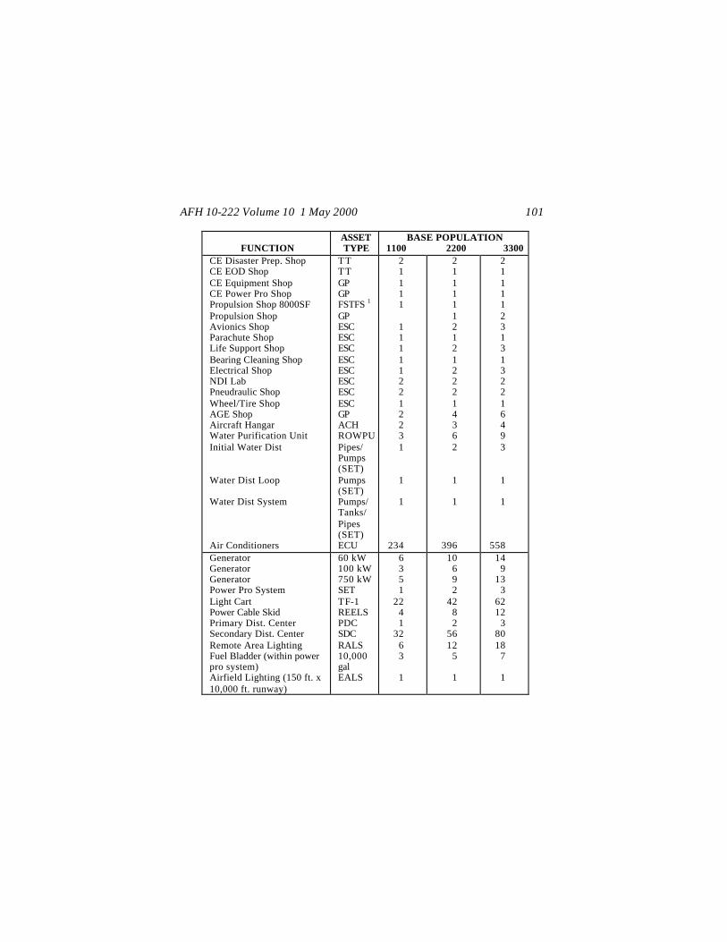
AFH 10-222 Volume 10 1 May 2000 101
FUNCTION
ASSET TYPE
BASE POPULATION 1100 2200 3300
CE Disaster Prep. Shop CE EOD Shop CE Equipment Shop CE Power Pro Shop Propulsion Shop 8000SF Propulsion Shop Avionics Shop Parachute Shop Life Support Shop Bearing Cleaning Shop Electrical Shop NDI Lab Pneudraulic Shop Wheel/Tire Shop AGE Shop Aircraft Hangar Water Purification Unit Initial Water Dist Water Dist Loop Water Dist System Air Conditioners
TT TT GP GP FSTFS 1 GP ESC ESC ESC ESC ESC ESC ESC ESC GP ACH ROWPU Pipes/ Pumps (SET) Pumps (SET) Pumps/ Tanks/ Pipes (SET) ECU
2 1 1 1 1
1 1 1 1 1 2 2 1 2 2 3 1
1
1
234
2 1 1 1 1 1 2 1 2 1 2 2 2 1 4 3 6 2
1
1
396
2 1 1 1 1 2 3 1 3 1 3 2 2 1 6 4 9 3
1
1
558 Generator Generator Generator Power Pro System Light Cart Power Cable Skid Primary Dist. Center Secondary Dist. Center Remote Area Lighting Fuel Bladder (within power pro system) Airfield Lighting (150 ft. x 10,000 ft. runway)
60 kW 100 kW 750 kW SET TF-1 REELS PDC SDC RALS 10,000 gal EALS
6 3 5 1
22 4 1
32 6 3
1
10 6 9 2
42 8 2
56 12
5
1
14 9
13 3
62 12
3 80 18
7
1

AFH 10-222 Volume 10 1 May 2000 102
Notes: 1 Changes in assets may require use of a medium type shelter, such as a large or medium FSFTS, Dome shelter, or a medium shelter system. Specific numbers of assets with the Harvest Falcon UTCs may cause variations in the above table. Always confirm what the final configuration of assets will be for your deployment. When dispersal is required, especially for larger deployments, then additional fuel bladders and a PDC may be required.
AFH 10-222 Volume 10 1 May 2000 103
Attachment 4
GENERAL INSTRUCTIONS FOR ASSEMBLING LOAD BREAK ELBOWS
These instructions may be used to assemble the load break elbows either with manufacturer’s or technical order instructions or when there are no specific instructions or technical orders available for the load break elbow. Warning: Ensure that the cable is not energized before attempting to assemble the load break elbows, as energized cables may be lethal. Determine the grounding pigtail length, which is found by:
For each cable/phase, measure the length from the farthest bushing position (either for parking or equipment connection) to the high voltage grounding location for the cable. Add 14 inches to the measurement to allow enough length for adequate clearance for connecting the ground, seating the elbow, and moving between parking stands and the connection bushing (of the generator, PDC, or SDC, as applicable).
When the cable is coming off the reel, that is when you are not starting with the end of a cable, hold the cable at its expected final position for installing the load break elbow and add the grounding pigtail length. Mark the cable at this location. Cut the cable at this location. Note: When measuring cables to cut-to-length, remember that the initial cable layout is laid on the surface and will be buried as time permits. Snake the cable sufficiently at both ends of the route between equipment items to provide enough slack to drop the cable into the trench. When measuring to cut the cable, take into account that additional slack is required prior to measuring and cutting the cable at the equipment item. The extra length for
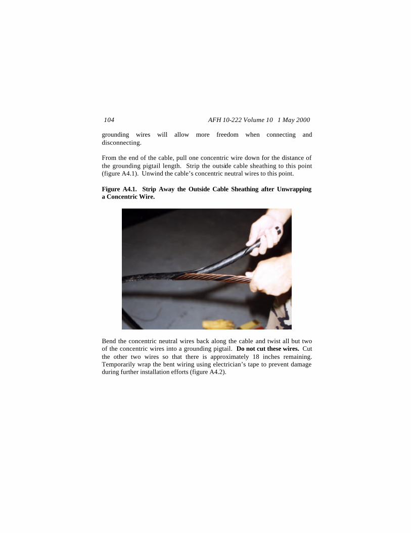
AFH 10-222 Volume 10 1 May 2000 104
grounding wires will allow more freedom when connecting and disconnecting. From the end of the cable, pull one concentric wire down for the distance of the grounding pigtail length. Strip the outside cable sheathing to this point (figure A4.1). Unwind the cable’s concentric neutral wires to this point. Figure A4.1. Strip Away the Outside Cable Sheathing after Unwrapping a Concentric Wire.
Bend the concentric neutral wires back along the cable and twist all but two of the concentric wires into a grounding pigtail. Do not cut these wires. Cut the other two wires so that there is approximately 18 inches remaining. Temporarily wrap the bent wiring using electrician’s tape to prevent damage during further installation efforts (figure A4.2).
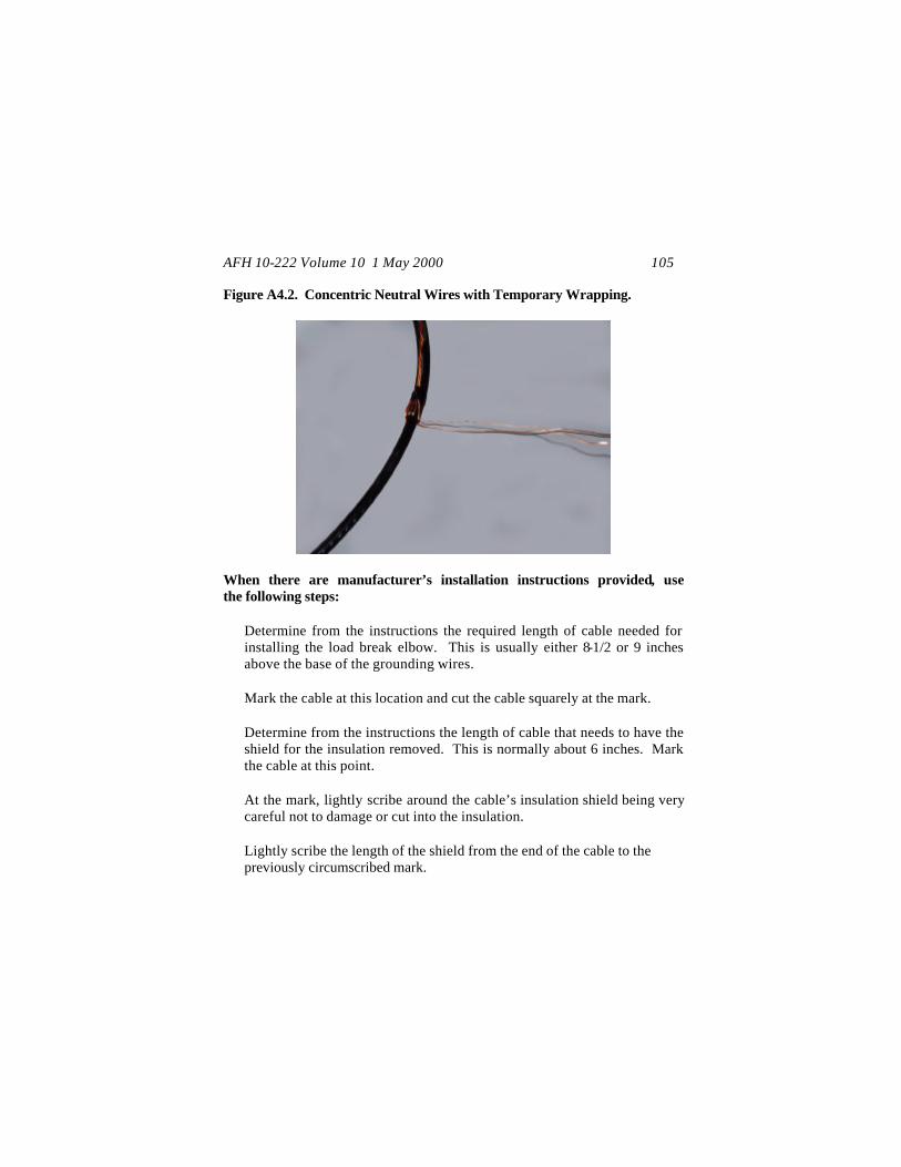
AFH 10-222 Volume 10 1 May 2000 105
Figure A4.2. Concentric Neutral Wires with Temporary Wrapping.
When there are manufacturer’s installation instructions provided, use the following steps:
Determine from the instructions the required length of cable needed for installing the load break elbow. This is usually either 8-1/2 or 9 inches above the base of the grounding wires. Mark the cable at this location and cut the cable squarely at the mark. Determine from the instructions the length of cable that needs to have the shield for the insulation removed. This is normally about 6 inches. Mark the cable at this point. At the mark, lightly scribe around the cable’s insulation shield being very careful not to damage or cut into the insulation. Lightly scribe the length of the shield from the end of the cable to the previously circumscribed mark.
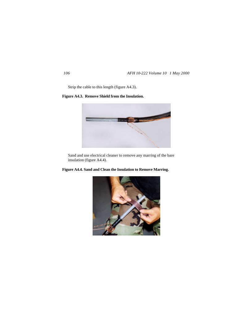
AFH 10-222 Volume 10 1 May 2000 106
Strip the cable to this length (figure A4.3).
Figure A4.3. Remove Shield from the Insulation.
Sand and use electrical cleaner to remove any marring of the bare insulation (figure A4.4).
Figure A4.4. Sand and Clean the Insulation to Remove Marring.

AFH 10-222 Volume 10 1 May 2000 107
Determine from the manufacturer’s instructions the length of bare cable that should fit into the contact bushing. Measure the recommended distance back from the end of the cable, usually 1-15/16 inches, and scribe the insulation jacket at this point. Carefully remove the insulation from the cable conductor without cutting or nicking the bare cable strands (figure A4.5).
Figure A4.5. Remove Insulation from Conductor.
If there are no instructions or dimension provided by the manufacturer, use the following steps:
Place the neck end of the load break elbow next to the cable such that the end of the elbow neck is at the end of the folded concentric neutral wires. This is normally about 8-1/2 inches. At the top of the load break elbow, mark the cable, and cut squarely at the mark (figure A4.6).

AFH 10-222 Volume 10 1 May 2000 108
Figure A4.6. Cut the Cable for the Distance of the Load Break Elbow from the Bent Wires.
Stick a piece of the previously cut off neutral wire into the opening at the base of the contact bushing and measure the inside length of the contact bushing. Note: the contact bushing may also be called various terms by the manufacturer or technical orders, such as the connector barrel, compression lug, or connector bushing. Using figure A4.7 as a guide, place the contact bushing next to the bell opening of the load break elbow such that the scribed-line bushing or formed-eye bushing aligns with the load break elbow’s opening for the probe (line A). Place the cut end of the cable next to the bushing at the distance previously measured for the inside length of the contact bushing (line B). Mark the cable at this location opposite where the base of the load break elbow neck just begins (line C).
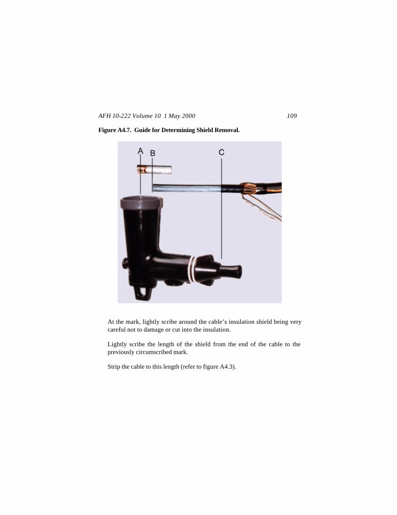
AFH 10-222 Volume 10 1 May 2000 109
Figure A4.7. Guide for Determining Shield Removal.
At the mark, lightly scribe around the cable’s insulation shield being very careful not to damage or cut into the insulation. Lightly scribe the length of the shield from the end of the cable to the previously circumscribed mark. Strip the cable to this length (refer to figure A4.3).
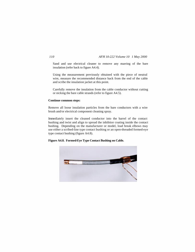
AFH 10-222 Volume 10 1 May 2000 110
Sand and use electrical cleaner to remove any marring of the bare insulation (refer back to figure A4.4). Using the measurement previously obtained with the piece of neutral wire, measure the recommended distance back from the end of the cable and scribe the insulation jacket at this point. Carefully remove the insulation from the cable conductor without cutting or nicking the bare cable strands (refer to figure A4.5).
Continue common steps: Remove all loose insulation particles from the bare conductors with a wire brush and/or electrical component cleaning spray. Immediately insert the cleaned conductor into the barrel of the contact bushing and twist and align to spread the inhibitor coating inside the contact bushing. Depending on the manufacturer or model, load break elbows may use either a scribed-line type contact bushing or an open-threaded formed-eye type contact bushing (figure A4.8). Figure A4.8. Formed-Eye Type Contact Bushing on Cable.
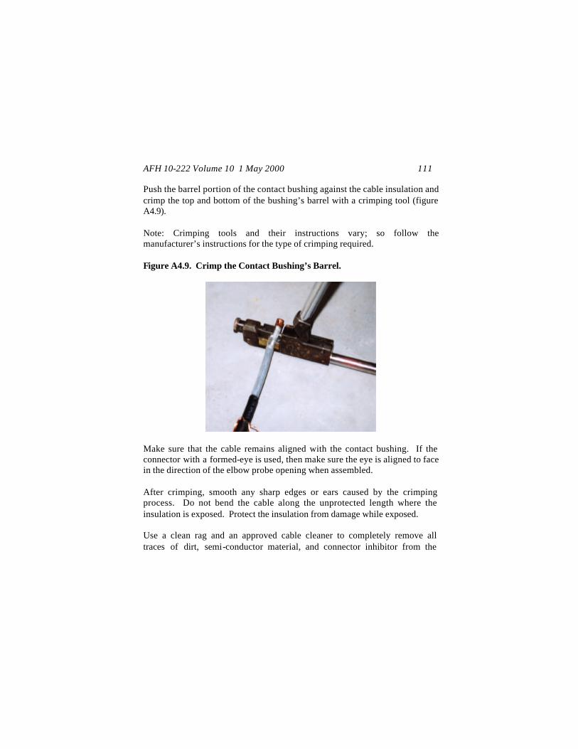
AFH 10-222 Volume 10 1 May 2000 111
Push the barrel portion of the contact bushing against the cable insulation and crimp the top and bottom of the bushing’s barrel with a crimping tool (figure A4.9). Note: Crimping tools and their instructions vary; so follow the manufacturer’s instructions for the type of crimping required. Figure A4.9. Crimp the Contact Bushing’s Barrel.
Make sure that the cable remains aligned with the contact bushing. If the connector with a formed-eye is used, then make sure the eye is aligned to face in the direction of the elbow probe opening when assembled. After crimping, smooth any sharp edges or ears caused by the crimping process. Do not bend the cable along the unprotected length where the insulation is exposed. Protect the insulation from damage while exposed. Use a clean rag and an approved cable cleaner to completely remove all traces of dirt, semi-conductor material, and connector inhibitor from the

AFH 10-222 Volume 10 1 May 2000 112
insulation and the remaining shield. Wipe from the bushing toward the bent concentric wires (figure A4.10). Figure A4.10. Clean the Insulation while Wiping Away from Contact Bushing.
Before pushing the cable conductor into the elbow, apply a small amount of silicon grease onto the exposed cable insulation (figure A4.11) and in the cable entrance of the elbow. For the formed-eye type contact, align the threaded eye with the probe opening of the open bushing cavity (bell). Install the cable by pushing the cable conductor into the entrance of the load break elbow until the assembly bottoms out on the elbow and/or is aligned with the hole for the probe assembly. For the formed-eye type contact, be sure to maintain the alignment of the formed eye with the bushing cavity while pushing the cable conductor into the elbow. Use a dry rag to remove all excess silicon grease from the neck area of the load break elbow.

AFH 10-222 Volume 10 1 May 2000 113
Figure A4.11. Apply Small Amount of Silicon Grease to Exposed Cable before Assembly.
Insert the probe assembly into bell and probe openings (figure A4.12). For the formed-eye type contact, make sure that the male threads of the probe just penetrate into the connector eye. Carefully engage the threads and hand tighten the probe. Be careful not to cross thread the connector and probe, as cross-threading causes loose connections. Using the wrench supplied with the load break elbow (figure A4.13), insert the short end of the wrench into the hole of the probe (figure A4.14).
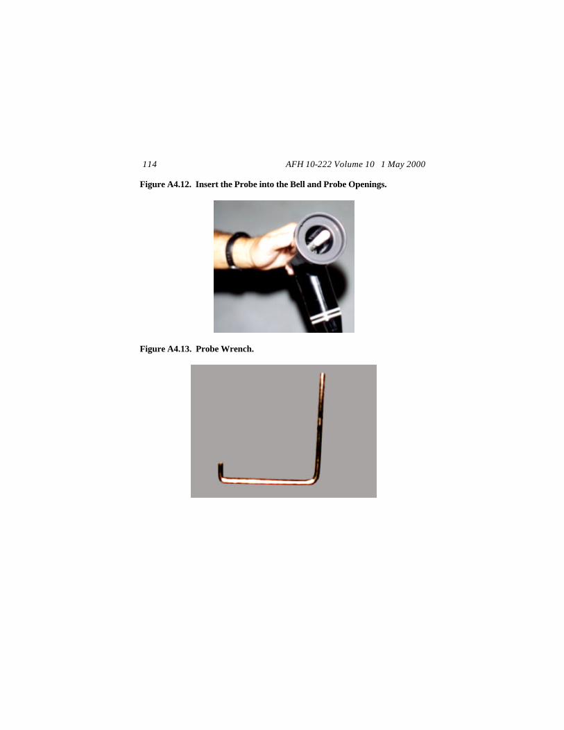
AFH 10-222 Volume 10 1 May 2000 114
Figure A4.12. Insert the Probe into the Bell and Probe Openings.
Figure A4.13. Probe Wrench.

AFH 10-222 Volume 10 1 May 2000 115
Figure A4.14. Short End of Wrench in Hole of the Probe.
Tighten the probe until the short end of the wrench bends about 90 degrees sideways (figure A4.15) and is permanently deformed. To seal the cable and load break elbow from extraneous debris and moisture, use electrician’s tape to wrap the end of the load break elbow and any exposed insulation shield (figure A4.16) for the area at the load break elbow’s base to the exposed wires. Depending on the manufacturer of the load break elbow, feed one or two strands of the concentric neutral through the grounding eye(s) (figure A4.17) of the Load Break Elbow. Twist and secure, cutting off any excess wiring. Caution: Take care not to damage the grounding eye(s) on the Load Break Elbow when connecting the concentric neutral wires.
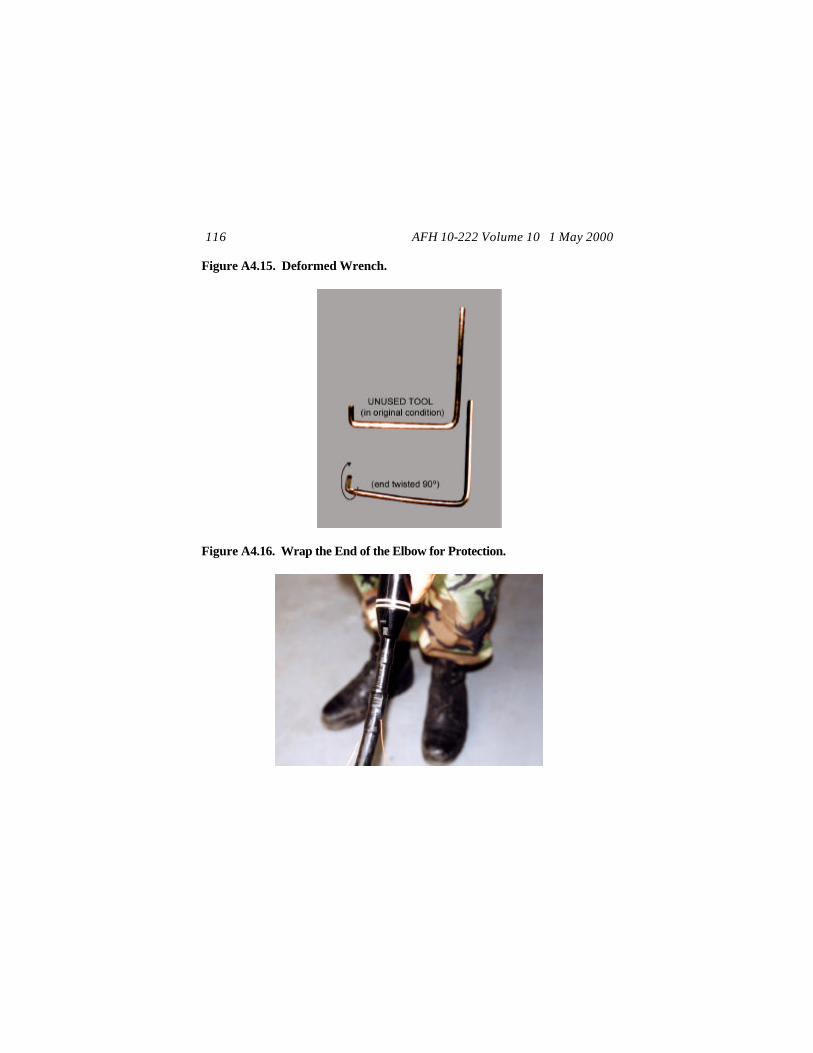
AFH 10-222 Volume 10 1 May 2000 116
Figure A4.15. Deformed Wrench.
Figure A4.16. Wrap the End of the Elbow for Protection.
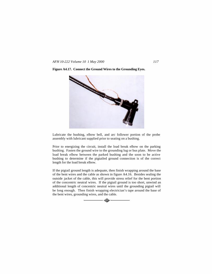
AFH 10-222 Volume 10 1 May 2000 117
Figure A4.17. Connect the Ground Wires to the Grounding Eyes.
Lubricate the bushing, elbow bell, and arc follower portion of the probe assembly with lubricant supplied prior to seating on a bushing. Prior to energizing the circuit, install the load break elbow on the parking bushing. Fasten the ground wire to the grounding lug or bus plate. Move the load break elbow between the parked bushing and the soon to be active bushing to determine if the pigtailed ground connection is of the correct length for the load break elbow. If the pigtail ground length is adequate, then finish wrapping around the base of the bent wires and the cable as shown in figure A4.16. Besides sealing the outside jacket of the cable, this will provide stress relief for the bent portion of the concentric neutral wires. If the pigtail ground is too short, unwind an additional length of concentric neutral wires until the grounding pigtail will be long enough. Then finish wrapping electrician’s tape around the base of the bent wires, grounding wires, and the cable.