aerodynamics note · 2013-09-05 · the electro-hydraulic valve situated in the fore-and-aft jack...
TRANSCRIPT
ARL-AERO-NOTE- 388 AR-001-606
, f"A
00 DEPARTMENT OF DEFENCEO DEFENCE SCIENCE AND TECHNOLOGY ORGANISATION
gel AERONAUTICAL RESEARCH LABORATORIES
cr. MELBOURNE, VICTORIA
AERODYNAMICS NOTE 388
SEA KING MK. 50 HELICOPTER FLIGHTCONTROL SYSTEM
A MATHEMATICAL MODEL OF THE FLYING CONTROLS
by L C
l C. R. GUY. ~ ~ SELL TIiS RLP j
Approved for Public Release. D~cLEL1ECTE
SJUL1419803
A
©COMMONWEALTH OF AUSTRALIA 1979
COPY No I. FEBRUARY, 1979
80 7 1' 0 28

CL AR-001-W0 -
AERONAUTICAL RESEARCH LABORATORIESDEFENCE SCIENCE AND TECHNOLOGY ORGANISATION
DEPARTMENT OF DEFENCE
CAERODYNAMCS#AO
SEA KING MK. 5 _ELICOPTER FLIGHT
. ONTR&L LSYSTEM, /
A MATHEMATICAL MODEL OF THE FLYING CONTROLS.
by.i.i
... .. 4 4 .
C. "
/~~ t- ~
SUMMARYA mathematical model for the flying controls of the Sea King Mk.50 helicopter is.i,° presented. The operation of the systems and components used in the flying controls of theaircraft is described first, followed by a detailed description of the construction andfunctioning of the mathematical model. Equations and diagrams for the model are included.
POSTAL ADDRESS: Chief Superintendent, Aeronautical Research Laboratoies,Box 4331, P.O., Melbourne, Victoria, 3001, Australia.
<%C

DOCUMENT CONTROL DATA SHEET
Security classification of this page: Unclassified
1. Document Numbers 2. Security Classification(a) AR Number: (a) Complete document:
AR-001-606 Unclassified(b) Document Series and Number: (b) Title in isolation:
Aerodynamics Note 388 - Unclassified(c) Report Number: (c) Summary in isolation:
ARL-Aero-Note 388 Unclassified
3. Title: SEA KING MK.50 HELICOPTER FLIGHT CONTROL SYSTEM;A MATHEMATICAL MODEL OF THE FLYING CONTROLS
4. Personal Author(s): 5. Document Date:Guy, Christopher R. February, 1979
6. Type of Report and Period Covered:Aerodynamics Note
7. Corporate Author(s): 8. Reference NumbersAeronautical Research Laboratories (a) Task:
RD 69/74/49. Cost Code: (b) Sponsoring Agency:
512090 DST
10. Imprint (Publishing establishment): 11. Computer Program(s)Aeronautical Research Laboratories, (Title(s) and language(s)):
Melbourne SKING (CSMP-10 (ARL) andFORTRAN IV)
12. Release Limitations (of the document)Approved for public release
F12-0O. Overseas: IN.0. IPR IlAI Bj CI DI E13. Announcement Limitations (of the information on this page):
No limitations
14. Descriptors: 15. Cosati Codes:Helicopters Flight control 0103Mathematical models Sea King (Helicopter) 1201
16. ABSTRACTk' A mathematical model for theflying controls of the Sea King MAii helicopter is
presented. The operation of the systems and components used in the flying controls of theaircraft is described first, followed by a detailed description of the construction andfunctioning of the mathematical model. Equations and diagrams for the model are included.
ILAAi

CONTENTS
1. INTRODUCTION 1
2. THE FLYING CONTROLS OF THE AIRCRAFT 1
2.1 General operation 1
2.2 Servo assistance 2
3. THE FLYING CONTROLS MATHEMATICAL MODEL 2
3.1 Fore-and-aft cyclic pitch control 2
3.2 Lateral cyclic pitch control 3
3.3 Collective pitch control 3
3.4 Tail rotor control 4
4. CONCLUDING REMARKS 4
NOMENCLATURE
REFERENCES
FIGURES
APPENDIX I: EQUATIONS FOR THE FLYING CONTROLS
APPENDIX H: AN ALTERNATIVE COLLECTIVE STICK MODEL
DISTRIBUTION

1. INTRODUCTION
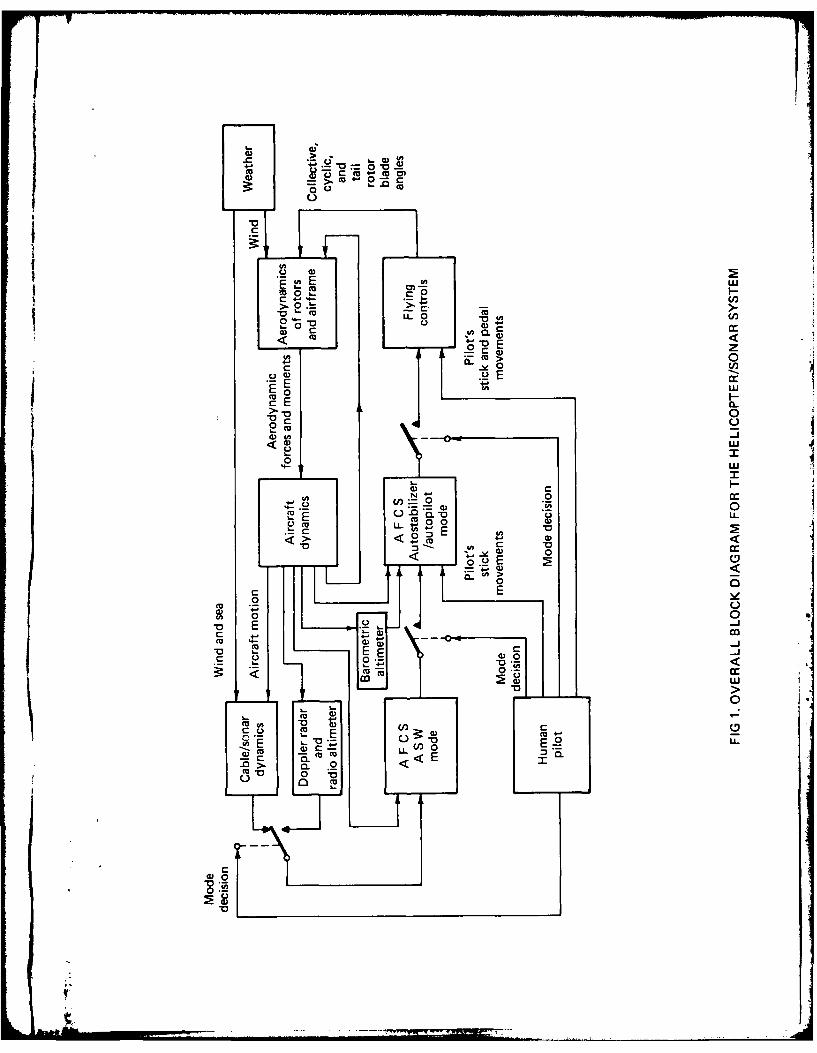
_The object of thisreport is to describe a mathematical model of the flying controls used inthe Sea King Mk.50 helicopter. This is used in conjunction with a mathematical model repre-senting the automatic flight control system (AFCS-Refs I and 2). Together, the flying controlsand AFCS form the control systems for the helicopter. The controls system model combineswith mathematical models of the aerodynamics/kinematics and sonar cable/transducer to forma complete helicopter/sonar dynamics model. This constitutes a major part of ARL taskRD 69/74/4; Aircraft Behaviour Studies-Sea King. An overall block diagram for the heli-copter/sonar system is shown in Figure 1.
The flying controls model presented here has many similarities to the flying controls usedin the Wessex helicopter mathematical model developed by Packer at Weapons ResearchEstablishmentt (Refs 3-6). Block diagrams for these have been included in the ARL versionof the Wessex mathematical model (Ref 7) and the programmed form of the control laws hasbeen incorporated in Reference 6. In addition, a simplified form of the Sea King flying controlshas been described in Reference 8.
The model presented here makes representations of the elements forming the flying controlsused in the aircraft (unlike the model outlined in Reference 8, which represents only the overallcontrol laws). For example, when modelling the cyclic fore-and-aft channel, representations ofthe trim actuator, cyclic stick, auxiliary and primary servo jacks, mehanical linkages (includingthe mixing unit) and rotor head are made. Non-linearities resulting from the physical constructionof the servos are included, as are stops limiting the travel of the cyclic control stick. Full descrip-tions of the flying controls used in the aircraft, including the primary and auxiliary servos, aregiven in References 9-12.
Section 2 of this document describes the operation of the systems and components usedin the flying controls of the aircraft. Section 3 outlines the mathematical model; this is subdi-vided into fore-and-aft cyclic pitch control, lateral cyclic pitch control, collective pitch controland tail rotor control. Block diagrams for the flying controls model are presented (Figs 2 to 5)and the equations describing the model are given in appendix I. An alternative to the collectivestick model presented in Section 3.3 is that developed by Packer for the Wessex helicoptermathematical model (Refs 6 and 7) and a description of this is given in Appendix II.
2. THE FLYING CONTROLS OF THE AIRCRAFT
2.1 General operation
The aircraft is controlled by changes in pitch of the main and tail rotor blades which areactuated either by pilot inputs or automatic flight control system (AFCS) inputs. The flying controlsconnect these inputs to the horns which control rotor blade angular position. Reference 9describes the flying controls of the aircraft and this'section is a summary of that document.Figure 6 is a diagram of the flying controls used in the helicopter.
The pilot's main controls are a cyclic stick which moves both fore-aft and laterally, acollective pitch lever and rudder pedals. The cyclic pitch flying controls function in the naturalsense, movement of the control stick producing a corresponding movement in flight throughvariation in cyclic pitch blade angle. The collective pitch lever controls the ascent and descentof the aircraft by simultaneous variation of the pitch of the main rotor blades and at the sametime generates the necessary corrective change in pitch of the tail rotor, known as yaw cross-feed,through the mixing unit. The rudder pedals operate the servo jack and levers which change thepitch of the tail rotor blades to obtain directional control.
t Now Defence Research Centre, Salisbury.
'J

In the aircraft, movement of the cyclic pitch stick and the collective pitch lever is transmittedto the auxiliary servo unit and mixing unit by means of control rods and bell-cranks (see Fig. 6).Control movement then passes via more control rods and mechanisms to the primary servojacks, which actuate a non-rotating star. Through a swashplate action, displacement of thenon-rotating star displaces a rotating star to effect a change of pitch to the blades throughpush-pull rods connected between the rotating star and the sleeve spindle horns. Until theyreach the mixing unit, collective pitch and cyclic pitch movements are independent, but themixing unit superimposes collective pitch on the cyclic pitch movement and supplies the yawcross-feed.
Movement of the rudder pedals is transmitted to the mixing unit in a similar manner tothe cyclic and collective pitch controls. However, from the mixing unit, control is transferredvia cables, push-pull rods and bell-cranks to the tail rotor pitch change mechanism. A yawforce link, which is installed in the tail rotor control run, operates as a control push-pull rodduring normal operation of the tail rotor controls, but in the event of the pilot making an over-ride control movement (pedal movement opposing AFCS operation), the force link compressesto actuate microswitches to disengage the AFCS signals. Also incorporated in the yaw channelauxiliary servo unit is a hydraulically operated pedal damper. This prevents rapid operation ofthe rudder pedals causing too-fast changes of pitch in the tail rotor blades.
2.2 Servo assistance
Servo assistance is provided to the flying controls through two sets of servo jacks. Threeprimary jacks, described in Reference 11, transmit control movements into changes in cyclicpitch by tilting the non-rotating star in the fore-aft and lateral planes. To provide collectivepitch movement, all three jacks operate together. Four auxiliary jacks (fore-aft, lateral, yaw andand collective-see Ref. 12), which are situated in the auxiliary servo unit, transmit controlmovements into servo assistance to the primary servo jacks and through the directional (yaw)controls into changes of pitch in the tail rotor. Note that the yaw auxiliary jack is the onlysource of servo assistance for the tail rotor controls. The auxiliary servo unit also translatesAFCS signals, via electrically-operated servo valves, into changes in pitch of the main and tailrotor through their respective control runs. In addition, the auxiliary servo unit provides supple-mentary cyclic pitch control from the beeper trim system. This provides fine adjustment of thecyclic stick through pilot operated trim switches and extension of authority for AFCS signals.In the collective and yaw channels, the authority extension is provided by open-loop springoperation of the auxiliary servos (see Refs 9 and 12).
3. THE FLYING CONTROLS MATHEMATICAL MODEL
3.1 Fore-and-aft cyclic pitch control (Fig. 2)
Figure 2 can be subdivided into the following parts: trim actuator, cyclic stick, auxiliaryservo and mechanical linkages, primary servo and mechanical linkages and rotor head. Adescription of each part is given below:
3.1.1 Trim actuator
The trim actuator, which enables fore-aft beeping of the cyclic stick to occur, comprisesthe electro-hydraulic valve situated in the fore-and-aft jack of the auxiliary servo unit and itsassociated circuitry. Switches S FWDt and S AFT are operated by the pilot to manually beepthe stick (forward and aft respectively) while S FWD H and S AFT H are actuated by theAFCS to provide automatic extension of authority. The beeping system is activated by closureof switch S PC and is used only during anti-submarine warfare (ASW) mode operation of theAFCS. For forward beeping, switch S FWD NU must be on through combination of S PCand S FWD or S FWD H, thus causing THE TDT to have value CCPI. Beeping aft is similar.THE TDT represents the rate of change of stick angle THE STK.
t Throughout this document, the format for variables is of the type used here. This enables
a computer program of the mathematical model to be written without changing variable names.
2

3.1.2 Cyclic stick
The cyclic stick is modelled using an integrator. If the trim release switch (S TRM REL)is on, THE STK takes the value THE PIL, the pilot's stick angle. This enables (manual) coarsecontrol of the cyclic stick. When S TRM REL is off, beeper operation (fine control) can takeplace where THE STK is formed through the integration of THE TDT. The limits on stickangular motion (±EL CPI) are applied to THE STK; the mid-point of THE STK is alignedwith the mid-point of the fore-aft cyclic blade pitch angle BIS.
3.1.3 Auxiliary servo and mechanical linkages
Constant CCPIO represents the gearing of the mechanical linkages between THE STK andthe auxiliary servo input position, D AX Pl. The servo itself is represented by the set of com-ponents between D AX PI and D AUX P, the output position; a sketch of a basic jack, takenfrom Reference 12, is given in Figure 7 and the model may be compared with this. VariableD XB P (Fig. 2) represents the position of points C and C' (Fig. 7) relative to a point on the jackbody and is determined by the ratio CCP2/CCP4 which is equivalent to CB/AB. The constantCCP5 represents the ratio DE/C'D and generates D VLV P, the pilot valve position. SignalD AUTO P, which is the flapper position in the servo valve, also contributes to D VLV Pthrough constant CCP3. The jack output velocity, D AP DT, is determined by the physicalcharacteristics of the pilot valve (pressures, orifice areas, etc) and this is non-linear with respectto D VLV P. A sketch showing the form of this function (FAP) is given in Figure 8. Outputposition D AUX P is obtained from D AP DT by integration and the feedback arrangementrepresents the geometry of the differential and pilot valve levers. The limits on jack outputposition are designated EL CP2.
3.1.4 Primary servo and mechanical linkages
The auxiliary jack output position (D AUX P) is transmitted via the mixing unit and othermechanical linkages to the primary jack input position (D PR P1). The overall gain for this isCCPI !. In the mixing unit some collective cross feed is added from D AUX A. The modellingof the primary jack is generally similar to that of the auxiliary jack except that no servo valveexists, a diagram of the primary servo jack is shown in Figure 9.
3.1.5 Rotor head
The variable D XB PP represents the output position of the fore-aft primary jack and thisis converted into the cyclic blade pitch angle(BIS) via the rotor head mechanism. The constantCCPI2 represents the gearing BIS/D XB PP.
3.2 Lateral cyclic pitch control (Fig. 3)
Similar to the fore-and-aft cyclic pitch control model.
3.3 Collective pitch control (Fig. 4)
This is similar to both fore-aft and lateral cyclic pitch models, except that:(i) The auxiliary jack has an open-loop spring incorporated in it to enable extension of
authority for the AFCS. When a large AFCS demand signal (D AUTO A) is appliedto the auxiliary servo, D XB A may exceed the open-loop spring compression limitEL CA4. This gives rise to a non-zero value of TH CS D which causes movement ofthe stick to occur, provided the friction lock (S FRIC) is off or the pilot is not over-riding stick movement (SC PIL is off).
The process used in the model to generate stick movement (i.e. the generation ofTH CS D from movement D DEAD A) is a simplification of the true behaviour or"the collective stick, where a torque is applied when D XB A exceeds EL CA4. Thistorque gives rise to stick movement provided the above conditions are again obeyed.
4[ A collective stick model simulating this behaviour more closely is described in appendix11. However, for general use, the version described above is considered adequate.
(ii) No cross-feed to the collective channel occurs in the mixing unit.
3

(iii) The terms THEC MD and THC LAG are incorporated in the rotor head model.THEC MD is the mid-value of collective blade pitch angle, THETA C and the THCLAG term represents hinge pitch-lag coupling which reduces blade pitch angle aslagging motion occurs.
(iv) Stick position (THEC ST) is measured relative to its full down position in this channel.In the pitch and roll channels, zero stick angle corresponds to the mid-point of cyclicstick travel in each plane.
(v) There is a non-linear relationship between collective blade pitch angle (THETA C) andstick angle (THEC ST) in this channel because of the open-loop spring action in theauxiliary servo. In the model, this is achieved through the values used for EL CAl-4.
3.4 Tail rotor control (Fig. 5)
This is similar to the collective pitch control model, except that:(i) S PEDLS represents a yaw force link switch which is on when the pilot applies pedal-
force and off when he removes foot pressure; the link enables the pilot to overridethe AFCS. In addition, the rate of change of pedal movement is limited by a pedaldamper. This is incorporated in the model as constant CCYI.
(ii) No primary jack exists in the tail rotor controls. The gearing between the auxiliaryjack output position (D AUX Y) and the tail rotor collective blade pitch angle(THETA T) is represented by constant CCY7. An offset term (TH CT MD) is includedtogether with limits on THETA T of EL CY4.
(iii) The collective to yaw cross-feed term (D AUX A multiplied by CCY8) is included inthe mixing unit.
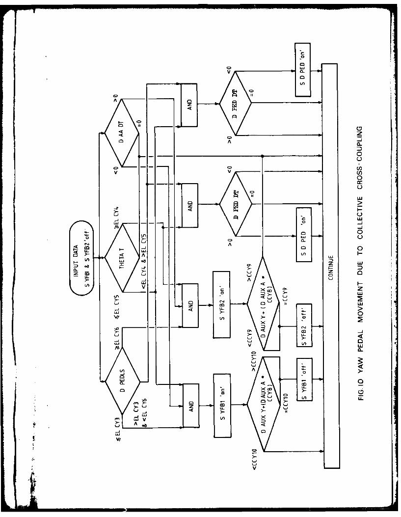
(iv) No equivalent of the hinge pitch-lag coupling term (THC LAG) exists.(v) In this channel, pedal movement can take place due to collective stick movement
when the pedals are in an extreme position and the tail rotor pitch limit is reached.In addition, if the tail rotor pitch limit is reached with the yaw pedals not at full travel,further pedal movement in the applied direction can only be achieved if collective pitchis first reduced. To model this behaviour, the circuitry illustrated in Figure 10 is usedto set the switches S YFBI, S YFB2 and S D PED shown in Figure 5.
4. CONCLUDING REMARKS
A detailed mathematical model of the flying controls for the Sea King Mk.50 helicopter hasbeen outlined. This is to be used in conjunction with a similarly detailed model of the automaticflight control system to form the complete control systems model. Representations of theelements used in the aircraft's flying controls have been made, including non-linearities. Theamount of detail included in the model makes it useful for analysing problems which may arisein service with the control system of the helicopter.
4

NOMENCLA TURE
AIS Cyclic blade pitch angles (lateral and fore-aft respectively)BIS }BIAS SP Bias spring position.
CCA . ....... ... I5'CCPI . ......... 12 ConstantsCCRI . ......... 121CCYI . ......... 1
D AA DT, D APDT, Auxiliary servo output velocity
D AR DT, DAY DTf
D AUTO A.... P, AFCS output signal...... R ....... Y }
DAUXA ...... P, Auxiliary servo output position...... R ........ Y
D AUX AO ..... PO, Auxiliary servo output position initial condition..... RO ...... YO
D AX AI ....... PI, Auxiliary servo input position..... RI . ...... YI
D AY FB Yaw auxiliary servo feedback position
D DEAD A, Auxiliary servo feedback position due to open loop springD DEAD Y fmechanism
DL TH CS Collective stick angle relative to middle of range of travel
D PA DT, D PP DT, Primary servo output velocityD PR DT
D PED DT Rudder pedals integrator input variable
D PEDLS Rudder pedals position
D PIL Y Pilot's rudder pedals position
D PR At ........ P, "Primary servo input position..... R !
D VLVA ....... . I Auxiliary servo pilot valve position.........R..........f
D VLV PA .... PP' Primary servo pilot valve position..... PR }DXBA ........ P, Auxiliaryservopilotvalve lever position!:... .R ........ Y
D XB PA ....... PP, Primary servo output position..... PRf
DXBPA PPO,. ...... PRO . .. - Primary servo output position initial condition
..... PR

D XSTK Collective stick cross-bar displacement
D YFBI ........ 2 Yaw auxiliary servo feedback quantities
EL CAI ......... 5,EL CPI ......... 3,EL CRI ......... 3, LimitsEL CYI ......... 6. EL MAX, EL MIN
FACR, FPAY Auxiliary servo pilot valve characteristic
FPC, FPP, } Primary servo pilot valve characteristic
THEI PIL Pilot's cyclic stick angles
PHI STKPHI STK Cyclic stick anglesTHE STK
THEI TDT Cyclic stick angular velocity
S AFT, S AFT H, Aft motion beeping switches
SC PIL Collective stick motion switch
SC STI .......... 9 Collective stick logic switches
S D PED Pedals hold switch
S FRIC Collective stick friction switch
S FWD, S FWD H, Forward motion beeping switches
S PC AFCS ASW mode switchesS RC
S PEDLS Yaw force link switch
S PIL A Stick friction release switch
S PS PORT H, Port motion beeping switches
S STBD, S STBD H, Starboard motion beeping switchesS STBD N ,
S TRM REL Cyclic stick trim release switch
S YFBI........ 2 Pedal movement switches
T ACCN Collective stick torque due to gravity and airframe motion
TCS D PL Pilot's collective stick angular velocity
T CS PL Pilot's collective stick angle
T EX External torque acting on collective stick
T FRIC Collective stick frictional torque
THC LAG Pitch-lag coupling for main rotor
TH CS D Collective stick integrator input variable
TH CS DD Collective stick angular acceleration
Liam, -

TH CS DP Collective stick angular velocity
THC SET Collective stick angle limitationsTHD SET 'TH CT MD Mid-points of tail and main rotor collective pitch anglesTHEC MDf respectively
TH CS MD Mid-point of collective stick angle
THEC ST Collective stick angle
THETA C Main and tail rotor collective blade pitch agles respectivelyTHETA T
THE TU Unlimited tail rotor collective blade pitch angle
T SPRING Torque due to bias spring on collective stick
T TOT Total torque acting on collective stick
I.-
4
l~~i,.a OKI! -III

REFERENCES
1. Guy, C. R. Sea King Mk.50 helicopter flight control system. A mathematicalmodel of the AFCS (autostabilizer/autopilot mode).ARL Aerodynamics Note 387, February 1979.
2. Guy, C. R. Sea King Mk.50 helicopter flight control system. A mathematicalmodel of the AFCS (ASW mode).ARL Aerodynamics Note 393, June 1979.
3. Packer, T. J. Wessex helicopter/sonar dynamics study. Initial report.
WRE Technical Note SAD 216, January 1969.
4. Packer, T. J. Wessex helicopter/sonar dynamics study. The mathematical modelof the helicopter aerodynamics and kinematics.WRE Technical Memorandum SAD 203, November 1969.
5. Packer, T. J. Wessex helicopter/sonar dynamics study. The mathematical modelof the sonar cable and transducer.WRF Report 951 (WR and D), May 1973.I 6. Packer, T. J. and Wessex helicopter/sonar dynamics study. The system simulation
Lane, R. C. program. WRE Technical Note 937 (WR and D), May 1973.
7. Williams, N. V., Wessex helicopter/sonar dynamics study.Guy, C. R., ARL program description and operation.Williams, M. J. and ARL Aerodynamics Note 385, February 1979.Gilbert, N. E.
8. Guy, C. R. Sea King Mk.50 helicopter/sonar dynamics study. A simplifiedcontrol systems mathematical model. ARL AerodynamicsReport 152, February 1979.
9. - A.P.(RAN)300-1--4.1 Chapter 19. Flying Controls.
10. - A.P.(RAN)300-1--4.1 Chapter 21-0. Hydraulic Power System-General
II. - A.P.(RAN)300-1-4.1 Chapter 21-1. Primary System.
12. - A.P.(RAN)300-1-4.1 Chapter 21-2. Auxiliary System.
0 c
IC-6-
> 0
-0 1-0-+- -0 -
+ 0CL-
00
0-J
L-J
00
4- u-
t4 2FC

LU,
00 CL C
0 C.0
C-w a.
0 I--ci) 0
+ +.
a.
(n IL
00.
+1. C.) x
0
4u > 0
-J 000
CL,
cnC.) C.)
____ ____ Y a- I
.2 0 0~Lw
x U-
o., 2 U, C6
Z.p :t. W W0a0 xU-
CL w - C.4 '
C.) -T) C.) L
LL LIJ L) Lwx u I L
0 o -.11 C.)u M
UL)L) C.)C.) 4

00
cc x
0
+ co
x * *
> -j
LU 00
). I +
00 0) i t-
0 cc z0 0
+0
- 0 -
DO 0 X
CN <0
U) 0 0r 0 L5
Lj+I cc
4 -J
r1
U 0 U- ZL
> a
x0 IL 0
C))0 le
0n -J L)-)xL U )F
<U D. 0
< <-xK0z
O06 00c2L
L ) U
.4.' -ic

0 +
M x
00U, 4
le LL U-
o > 0> -i
W4 0 0
Co-
to >
x I--
00C4J
+1~ 00) 2
040
> I--i [ z
0 0
<, 00
4) D
0 le0
cn -J I
-zx <
4U u
U L< <

LS I
LU
I-r
D L)z) 0
C,)q
LU D
-J C
a I
a .) C.)z Ii0L
C.))
0 C0
xJ 4W
CV
0 <-
cl

/
E0I..
Ca,Lu
U)-J0I-
SM~ 00
~z-J
a- LL4~. SOCa SM SMa. S-a55 40 U..
~s SM as
S C.)
SM, 4 SM,-~.0 40 q.,tl
SM lJ tIW SM4 0Wa
SM,
U..
I

MIXING UNIT
PRESSURE
INPUT FROMF.C.S.
SERVO VALVE
FLAPPER
TRETURN'PRESSURE IN* UTPRSR VALVE
CO PISTON U
BY-PASS VALVE AND -ACTUATING CYLINDER nSHORT -'"""
PIOTPILOT VALVELEVER
>-- F"PRESSURE
DIFFERENTIALSLPYLEVER RETURN
~LINKREDUCED i
PRESSURE
AUXILIARY PRESSURE o ref SS12)ONOPSUt (INPUT LINKAGE MOVED UPWARD)
PILOT INPUT PESRDROP
-O PILOT'S INPUT
MOVEMENTS
FEED BACK --- m,~MOVEMENTS
* FIG 7. BASIC AUXILIARY JACK (taken from ref. 12)

D AP DT
DVLV P
FIG 8. FORM OF FUNCTION FAP

'output torotor head
VALV E
EPressureDReturn
DESCENDING
LINK
FLYING CONTROLINPUT
FIG 9. PRIMARY SERVO JACK (taken from ref. 11)
-- - L ...
v~ 0-
C3i
L--JC3~
C3-zw
LI-
%--J
0o 0
< AA
u,-CL z Liaz Li z
- u
UJ 0
u.J > -.
V/ 0
L.J CU-
AN 0
LiI;. LiA

APPENDIX I: EQUATIONS FOR THE FLYING CONTROLS
1. FORE-AND-AFT CYCLIC PITCH CONTROL (Fig. 2)
1.1 Trim actuator
If S PC is offS FWD NU = S FWD and(1)
S AFT NU = S AFTIf S PC is onS FWD NU = S FWD H and (1.2)
If SFWD NU is off }(1.3)SH AT NU = S0F
If S. WD NUis onTHE DT =CCP1
If S FT NJis off 1)
If SAFT NU is on(.6THE TDT = -CCP9}
1.2 Cyclic stick
If S TRM REL is off(17THE STK = f(THE TDT) dt
If S TRM REL is on(18THE STK THE P1L
If ITHE STKI < JEL CP1 1(19THE STK = THE STK
If iTHE STKI > EL CP1 1(.0THE STK = EL CP1 * SIGN THE STK
1.3 Auxiliary servo and mechanical linkagesD AX P1 = CCP1O * THE STK (.1
D XB P =(CCP2 *D AX PI) -(CCP4 *D AUX P) (1.12)
D VLV P -(CCP5 * D XB P) - (CCP3 *D AUTO P) (1.13)
D AP DT =Function (D VLV P) (1.14)
D AUX P=(D AP DT) dt (1.15)
IfID AUX PI < JEL CP2I 1.6
D AUX P = D AUX PJ
If ID AUX PI > JEL CP2ID AUX P IEL CP21 SIGN DAUX P

1.4 Primary servo and mechanical linkages
D PR PI =(CCPI I *DAUX P) +(CCP8 D AUX A) (.8
D VLV PP (CCP6 * D PR PI) - (CCP7 *D XB PP) (.9
D PP DT = Function (D VLV PP) (1.20)
D XB PP = j (D PP DT) dt (1.21)
If ID XBPPI < IEL CP31I1.2D XB PP = D XB PP
If ID XB PPI - JEL CP31I1.3D XB PP = EL CP31 * SIGN D XB PP
1.5 Rotor head
BIS = CCP12 * D XB PP (1.24)
2. LATERAL CYCLIC PITCH CONTROL (Fig. 3)
2.1 Trim actuator
If S RC is offS STBD N = S STBD and (2.1)S PORT N = S PORTJ
if S RC is onS STBD N =S STBD H and (2.2)S PORT N = S PORT HJ
If S STBD N is off(23PHI TDT = 0(2)
If S STBD N is on(24PHI TDT =CCRI
If S PORT N is off(25PHI TDT = 025
If S PORT N is on(26PHI TDT = -CCR9
2.2 Cyclic stick
If STRM REL is off (27PHI STK f (PHI TDT) dt(2)
If STRM REL ison(28PHI STK =PHI PIL(28
If IPHI STKI < IEL CR1 (.9PHI STK = PHI STK
If PHI STKI >- EL CRI IPHI STK =EL CR1I1 * SIGN PHI STK (.0
2.3 Auxiliary servo and mechanical linkages
D AXRI =CCRIO *PHI STK (2.11)
D XB R (CCR2 D AX RI) -(CCR4 D AUX R) (2.12)
D VL-V R. = -(CCR5 * D XB R) - (CCR3 *D AUTO R) (2.13)
D AR DT = Function (D VLV R) (2.14)
D AUX R =J (D AR DT) dt (2.15)
If ID AUX RI < IEL CR21 (2.16)D AUX R. = D AUX Rf
If ID AUX RI > JEL CR21 (.7D AUX R. = JEL CR21 * SIGN D AUX R (217
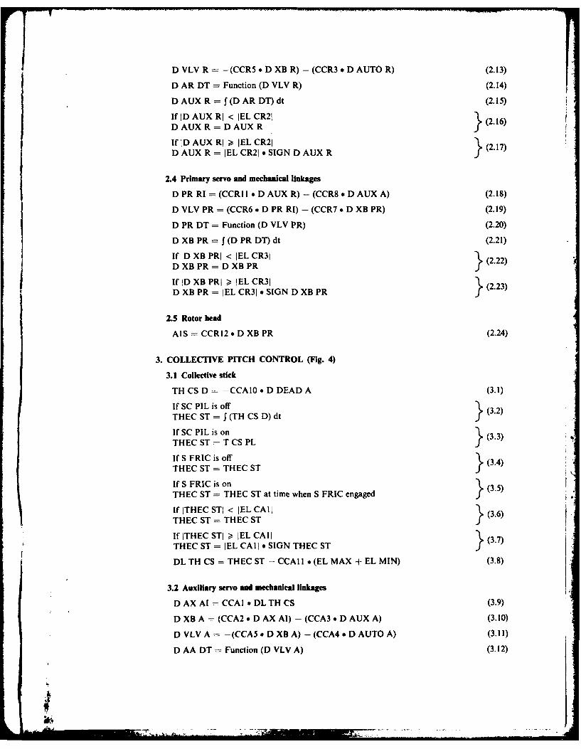
2.4 Primary servo and mechanical linkages
"DPR RI =(CCRI I *DAUX R) -(CCR8 D AUX A) (2.18)
" VLV PR =(CCR6 * D PR RI) - (CCR7 *D XB PR) (2.19)
" RDT = Function (D VLV PR) (.0
D XB PR = I (D PR DT) dt (2.21)
If ID XBPRI < JEL CR31 (.2D XB PR = D XB PR3.(2)
If ID XBPRI , JEL CR31 (.3D XB PR = JEL CR31 * SIGN D XB PR (.3
2.5 Rotor head
AIS =CCR12 * D XB PR (2.24)
3. COLLECTIVE PITCH CONTROL (Fig. 4)
3.1 Collective stick
TH CS D = -CCAIO * D DEAD A (3.1)
If SC PIL is off(32THEC ST =5 (TH CS D) dt(32
If SC PIL is onTHEC ST = T CS PL 3 33
If S FRIC is off }34THEC ST = THEC ST(34
If S FRIC is onTHEC ST = THEC ST at time when S FRIC engaged
If ITHEC STI < JEL CAlL (.6THEC ST = THEC ST j 36
If ITHEC STI >, EL CAI (.7THEC ST = IEL CAI I * SIGN TI-EC ST(3)
DL Ti- CS = THEC ST - CCAI I * (EL MAX + EL MIN) (3.8)
3.2 Auxiliary servo and mechanical linkages
D AX Al =CCAI * DLTH CS (3.9)
D X8A =(CCA2 *D AX A) - (CCA3 *D AUX A) (3.10)
D VLV A = -(CCA5 * D X8A) - (CCA4 D AUTO A) (3.11)
D AA DT = Function (D VLV A) (3.12)

D AUX A J(D AA DT) dt (3.13)
If1D AUX Al < IELCA21D AUX A D AUX A }(3.14)If ID AUX Al -> iEL CA21D AUX A = JEL CA2I * SIGN D AUX A
IfITD XB Al < 'EL CA41
D DEAD A (3.10
If IDXB Al - !EL CA41 (3.17)D DEAD A = (ID XB Al - JEL CA41) * SIGN D Xe AJ
3.3 Primary servo and mechanical linkages
D PR Al =CCA6 * D AUX A (3.18)
VLV PA = (CCA8 * D PR Al) - (CCA7 *D XB PA) (3.19)
PA DT Function (D VLV PA) (3.20)
D XB PA = (D PA DT) cdt (3.21)
If D XB PA! < JEL CA31 3.2D XB PA =D XB PA)If ID XB PA! >- EL CA31 (3.23)D XB PA = JEL CA3'* SIGN D XB PA
3.4 Rotor head
THETA C = (CCA9 * D XB PA) -I- (TI-C LAG) + (THEC MD) (3.24)
4. TAIL ROTOR CONTROL (Fig. 5)
4.1 Rudder pedals
D PED DT = -CCYI * D DEAD Y (4.1)
If S PEDLS is offD PEDLS f (D PED DT) dt(42
If S PEDLS is onD PEDLS = D P1L Y f(4.3)If D PEDLS: < EL CYI; 44D PEDLS = D PEDLS ) 44
If iiDPEDLS! -> EL CY ID PEDLS =EL CV I! SIGN D PEDLS (4.5)
4.2 Auxiliary servo and mechanical linkages
D AX YI CCY6 *D PEDLS (4.6)
D XB Y =(CCY2 D AX YI) -(CCV3 *D AY FB) (4.7)
D VLV Y= -- (CCY4 *D X8Y) -(CCY5*D AUTO0Y) (4.8)
D AY DT = Function (D VLV Y) (4.9)
D AUX Y =5f (D AY DT) dt (4.10)
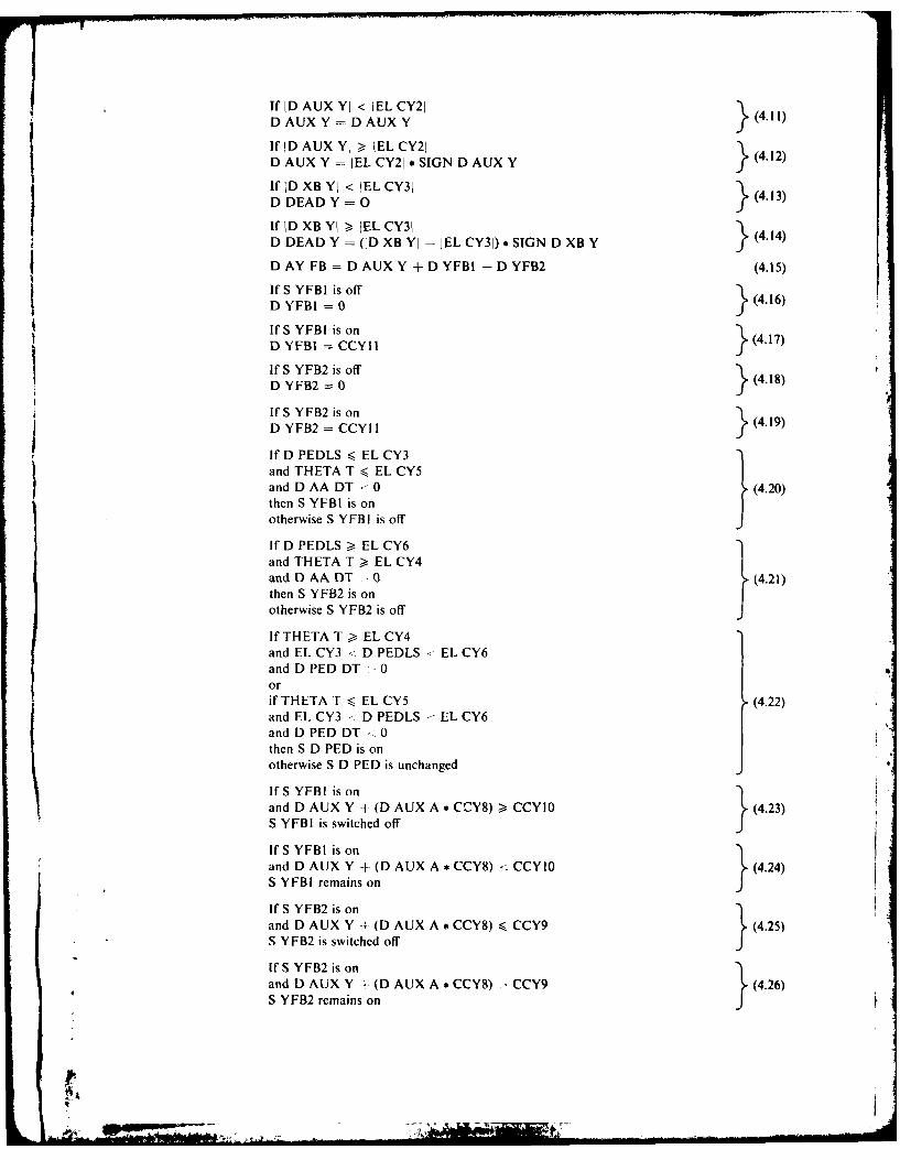
If ID AUX YI < IEL CY21
D AUX Y = D AUX Y
D AUX Y = JEL CY21 * SIGN D AUX~fDUY Y LC }( 2
If ID Xe YI < EL CY31 4.3D DEAD Y = (43
If ID XB Yl - EL CY31 (414D DEAD Y (11D XB YI - JEL CY3i) * SIGN D XB Y
DAY FB =DAUXY±+DYFBI -DYFB2 (.5
If SYFB1 is off (.6D YFBI =0fIf S YFBI is on "
DYFBI CCY11(4.17)Df YFB~Isofl' }Df YFB2 is of (4.18)
If S YFB2 is onD YFB2 = CC'I 3 (4.19)
j If D PEDLS -< EL CY3and THETA T <- EL CY5Iand D AA DT -0 (4.20)then S YFBI is on}otherwise S YFBI is off
If D PEDLS >- EL CY6and THETA T -> EL CY4and DAADT -0 (4.21)then S YFB32 is on}otherwise S YF132 is off
If TH-ETA T -> EL CY4and EL CY3 <- D PEDLS EL CY6and DPEDDT 0Oorif THETA T -< EL CY5 (4.22)and EL CY3 -D PEDLS E IL CY6and D PED DT -0then S D PED is onotherwise S D PED is unchanged
If S YFBI is onand D AUX Y + (D AUX A * CCY8) >- CCYIO ~.(4.23)S YFBI is switched offJ
If'S YFBI is on ( .4and D AUX Y + (D AUX A * CCY8) < CCYIO (.4
S YFIII remains on
If'S YFB2 is onand D AUX Y + (D AUX A *CCY8) CCY9 (4.25)
S YFB2 is switched off}
If S YFB2 is onand D AUX Y + (D AUX A *CCY8) -CCY9 ~.(4.26)S YFB2 remains onJ

4.3 Mechanical linkages and rotor head
THE TU = (TH CT MD) + (CCY7 *(D AUX Y + CCY8 *D AUX A)) (4.27)
If ITHE TUI < IEL CY41 (4.28)THETA T THE TU
If ITHE TUI , JEL CY41 (4.29)THETA T JEL CY41 SIGN THE TUJ

APPENDIX H: AN ALTERNATIVE COLLECTIVE STICK MODEL
As stated in Section 3.3, a simplification of the behaviour of the collective stick has beenused in the flying controls model. A more comprehensive collective stick model, which deter-mines the torque required to move the stick, is presented here. This was derived by Packer andused in the Wessex mathematical model (Refs 3-6). A diagram for the model is shown inFigure Al and some comments about its operation are given below:
(i) THEC ST is the angle of the collective stick relative to the helicopter x - axis.
(ii) DL TH CS is the angle of the stick relative to the middle of its range of travel.(iii) THC SET is the initial condition for THEC ST after an integrator reset arising
through SC ST7; it represents the stick angle at a mechanical stop.(iv) When SC ST8 is on, the stick has reached a mechanical stop.(v) If SC ST6 is on, the pilot is moving the stick towards its nearer stop, or pushing~it against this.
(vi) D XSTK is the displacement of the cross-bar joining the pilot's and co-pilot's collec-tive sticks.
(vii) T SPRING is the torque acting at the c. of g. of the collective stick, caused by the
balance spring.(viii) T ACCN is that component of torque acting on the collective stick c. of g. due to
gravity and the motion of the airframe at the point where the stick is pivoted.(ix) If SC ST4 is on, the stick is moving towards or is being pushed against, the closer
mechanical stop, by the external torque ( EX). Note that the stick cannot moveaway from the stop unless T EX exceeds the frictional torque (T FRIC) and is ofopposite sign.
(x) SC ST7 indicates when the stick is at a mechanical stop and is being driven into it.(xi) The total torque acting on the stick c. of g. (T TOT) is obtained by subtracting the
frictional torque (T FRIC), which opposes motion, from T EX.(xii) The angular acceleration of the stick relative to the helicopter (TH CS DD) is obtained
by dividing T TOT by the moment of inertia of the stick about its pivot (I/CCAI2).(xiii) The angular velocity of the stick relative to the helicopter (TH CS DP) is obtained
by integrating TH CS DD.(xiv) Switch SC STI is engaged when the stick has come to rest.(xv) Switch SC ST2 is engaged when the absolute value of the external torque (T EX) is
less than (or equal to) the absolute value of the frictional torque (T FRIC).(xvi) SC ST3 is on when both SC STI and SC ST2 are on, i.e. when the stick is at rest
and there is insufficient torque to move it.(xvii) S PIL A is a switch which enables the pilot to more the stick freely.
(xviii) When S PIL A is on and the stick is not at either stop, both SC ST5 and SC ST9are on and the stick's angular velocity (TH CS DP) is determined by the pilot (TCSD PL) through THD SET.
(xix) S FRIC is the friction lock on the collective stick. When this is on the stick maynot be moved.

c.2,
CL'cnw
x.co0
zw
7 0
ui (ww
LLL

DISTRIBUTION
Copy No.
AUSTRALIA
Department of Defence
Central OfficeChief Defence ScientistIDeputy Chief Defence Scientist 2Superintendent, Science and Technology Programs 3Australian Defence Scientific and Technical Representative (U.K.) 4Counsellor, Defence Science (U.S.A.) 5Defence Library 6Joint Intelligence Organisation 7Assistant Secretary, D.I.S.B. 8-23
Aeronautical Research LaboratoriesChief Superintendent 24Library 25Superintendent, Aerodynamics Division 26Divisional File, Aerodynamics Division 27Author: C. R. Guy 28-29D. C. Collis 30-33D. A. Secomb 34D. E. Hatton 35
Materials Research LaboratoriesLibrary 36
Defence Research Centre SalisburyLibrary 37
Central Studies EstablishmentInformation Centre 38
Engineering Development EstablishmentLibrary 39
RAN Research LaboratoryLibrary 4
Navy OfficeNaval Scientific Adviser 41Director, Naval Aircraft Engineering 42Director, Naval Aviation Policy 43AMAFTU, Nowra 4
Army OfficeArmy Scientific Adviser 45Royal Military College Library 46U.S. Army Standardisation Group 47
Air Force OfficeAircraft Research and Development Unit 48Air Force Scientific Adviser 49

Engineering (CAFTS) Library 50D. Air Eng.-AF 51HQ Support Command (SENGSO) 52
Department of Productivity
Government Aircraft FactoriesManager/Library 53
Department of TransportSecretary/Library 54
Statutory, State Authorities and IndustryCommonwealth Aircraft Corporation, Manager 55Hawker de Havilland Pty Ltd, Librarian, Bankstown 56
University and CollegesSydney Professor G. A. Bird 57RMIT Mr H, Millicer 58
CANADANRC, National Aeronautical Establishment, Library 59
FRANCEAGARD, Library 60Onera, Library 61Service de Documentation, Technique de I'Aeronautique 62
INDIANational Aeronautical Laboratory, Director 63Hindustan Aeronautics Ltd, Library 64
NETHERLANDSNational Aerospace Laboratory (NLR) Library 65
UNITED KINGDOMAeronautical Research Council, Secretary 66Royal Aircraft Establishment, Library. Farnborough 67Royal Aircraft Establishment, Library. Bedford 68Westland Helicopters Ltd 69
UNITED STATES OF AMERICANASA Scientific and Technical Information Facility 70American Institute of Aeronautics and Astronautics 71
Spares 72-86
I.: