aec research - digital library/67531/metadc864731/m2/1/high_res...li thi um niobate, a relatively...
TRANSCRIPT

ON THE PIEZOELECTRIC PROPERTIES OF LlTHl UM NIOBATE
AEC RESEARCH &
DEVELOPMENT REPORT
- - . , .* .;.> r J . - . , - - 4 -1. % . . . .
> - - , . . *.+<*&4"-< -.>-- , 5%;. .. B kf T Li , . i x m '
- ' BA-LE'MEMORPPL I!S~TUTE ' . 'NORTHWEST
PACIFIC NORTUWESf LABORATORIES
SATTEF,~*E BOULEV4i@& f.0 BOX 999, RICHLAND, WASHINGTON 99352 A ? $ a --,. #, .-;<&$ $.+ < "
? . :, ,, , ' * I * : ' L

LEGAL N O T I C E
,' This reporf was prepared as an account of work sponsered by +he United States G~verhment. Neither h e United States nor the United States Atomic Energy Comd
, mission, nor any of their employees, nor any of their contractors, subcontodo~.lr,, or ,.. their employees, makes any warranty, express or implied, or assumes any legal
.ligbility or responsibility for the accuracy, completeness or usefulness of any informa- tion, appar~tus, product or process disclosed, or represents h a t its use would not infringe privately owned rights.
PACIFIC NORTHWEST LABORATORY RICHLAND, WASHINGTON
operated by BATTELLE MEMORIAL INSTITUTE
for the - UNITED STATES ATOMIC ENERGY COMMISSION UNDER CONTRACT AT(45.1)-1830 I

BNWL- 1436
UC-37, Instruments
EFFECTS OF GAMMA RADIATION ON THE PIEZOELECTRIC
PROPERTIES OF LITHIUM NIOBATE
R. W. Smith ( a )
Appl i e d Physics and Nondestructive Test ing Department Systems and Electronics D iv i s ion
Ju ly 1970
BATTELLE MEMORIAL INSTITUTE PACIFIC NORTHWEST LABORATORIES
RICHLAND, WASHINGTON 99352
(a) Now employed by WADCO Corp., a Subsidiary o f Westinghouse E l e c t r i c Corp. , under AEC Contract No. AT(45-1)-2170

Printed i n the Uni ted S ta tes of America Available from
Clearinghouse fo r Federal Sc i en t i f i c and Technical Information National Bureau of Standards, U.S. Department of Commerce
Spr ingf ie ld , V i rgi ni a 221 51 Price : Printed Copy $3.00; Microfiche $0.65

EFFECTS OF GAMMA RADIATION ON THE PIEZOELECTRIC PROPERTIES OF LITHIUM NIOBATE
R. W. Smith
ABSTRACT
L i t h i u m niobate can be used t o significantly extend the operating temperatures of ultrasonic transducers. Since some high-temperature transducer appl ica t i ons involve exposure t o nuclear radiation, i t i s important to determine the e f fec t of th i s radiation on the piezoelectric propertiesof the transducer crystal . In t h i s work we measured the e f fec t
of gamma radiation on the piezoelectric properties of lithium niobate
crystals. We exposed x-cut and z-cut lithium niobate transducer plates to gamna radiation from a 6 0 ~ o source. The electromechanical coup1 ing factor , the d ie lec t r ic constant and the frequency constant were measured
10 before exposure and a t periodic intervals up t o 10 R , to tal dose. We could detect no significant change i n any of these parameters up t o
10 10 R. This indicates that lithium niobate i s we1 1 suited for appl ica- tions involving exposure to high levels of gamma radiation.
i i i


BNWL- 1436
CONTENTS
INTRODUCTION . SUMMARY AND CONCLUSIONS
DISCUSSION
EXPERIMENTAL . RESULTS . ACKNOWLEDGEMENTS . REFERENCES . D I S T R I B U T I O N .


EFFECTS OF GAMMA RADIATION ON THE PIEZOELECTRIC PROPERTIES OF
LITHIUM NIOBATE
R. W. Smith
INTRODUCTION
L i t h i um niobate, a r e l a t i v e l y new f e r r o e l e c t r i c c r y s t a l , i s an
impor tan t ma te r i a l because i t can be used t o s i g n i f i c a n t l y extend the
opera t ing temperature o f u l t r a s o n i c transducers. Due t o i t s h igh c u r i e
temperature (1210 "C) and the h igh p i e z o e l e c t r i c coup1 i n g f a c t o r s
associated w i t h some cuts, improved h igh temperature u l t r a s o n i c t rans-
ducers are possib le. Since some high- temperature transducer app l i ca t i ons
i nvol ve exposure t o nuc lear r a d i a t i o n (e. g. , under-sodi um viewing and
acoust ic emission mon i to r ing) , i t i s important t o determine the e f f e c t
o f t h i s r a d i a t i o n on the p i e z o e l e c t r i c p rope r t i es o f the transducer c r y s t a l .
I n t h i s work we measured the e f f e c t o f gamma r a d i a t i o n on the piezo-
e l e c t r i c p rope r t i es o f l i t h i u m n iobate c rys ta l s . The e f f e c t o f gamna
exposure was determined by i r r a d i a t i n g some c r y s t a l s w i t h a gamma source
and measuring the p i e z o e l e c t r i c electromechanical coupl ing fac to r , t he
d i e l e c t r i c constant, and t h e frequency constant a t p rogress ive ly h igher
l e v e l s o f 6 0 ~ o rad ia t i on . This r e p o r t out1 ines the experimental procedure
and presents our r e s u l t s o f the i r r a d i a t i o n e f f e c t s .
SUMMARY AND CONCLUSIONS
We exposed x- cut and z- cut l i t h i u m n iobate transducer p la tes t o
g a m r a d i a t i o n from a 6 0 ~ o source t o determine the e f f e c t o f t h i s rad ia-
ti on on the p i e z o e l e c t r i c p rope r t i es o f the mater i a1 . The e l ectromechani - ca l coupl ing fac to r , t he d i e l e c t r i c constant and the frequency constant
10 were measured before exposure and a t pe r iod i c i n t e r v a l s up t o 10 R, t o t a l
dose.
We could de tec t no s i g n i f i c a n t change i n any o f these parameters up 10 t o and i n c l u d i n g the maximum exposure o f 10 R. This r e s u l t i nd i ca tes
t h a t li t h i um n iobate i s w e l l s u i t e d f o r app l i ca t i ons i n v o l v i n g exposure
t o h igh l e v e l s o f gamma rad ia t i on .

DISCUSSION
The piezoelectric coupling factor i s a d i rec t measure of the strength of the piezoelectric ac t iv i ty of a crystal . The piezoelectric coupling factor can be defined as the square root of the r a t io of the electr ical energy available from a crystal t o the total mechanical energy i n p u t . An
a l ternat ive definit ion i s the square root of the ra t io of the mechanical energy available to the total i n p u t e lectr ical energy. The coupling factor for a particular mode of vibration i s thus a measure of the effectiveness of the crystal as an electromechanical energy converter for t h a t par t i -
cul a r mode. Both x-cut (shear) and z-cut (longi t u d i nal ) 1 i thi um niobate are of
in te res t for ultrasonic transducer ap l icat ions, because both of these cuts have f a i r ly pure vibrational modes. The z-cut plate i s a pure extensional mode. An x-cut plate has two shear modes; however, the coup- ling to one of these modes is very weak while the other i s quite strong. The coupling factors fo r these two cuts can be readily measured to indicate the strength of the piezoelectric act ivi ty . Since these cuts are important
for transducer applications and the i r coupling factors can be easi ly measured, both x and z-cut plates were irradiated during the experiment. The coupl i ng factors were measured a t progressively higher 1 evels of radi a- tion from a 6 0 ~ o source t o detect any decline i n the piezoelectric act ivi ty .
The coupling factor can be measured i n several ways. (2-9) The
technique recomnended i n the IRE Standards on Piezoelectric Crystals , 1957 and 1958 involves measuring the ser ies resonant frequency fs and the paral l e l resonant frequency f for one particular vibrational mode
P of the crystal . The effect ive coupl i ng factor k for that mode i s then cal cul ated from
In practice, the parallel resonance frequency may be obscured by
unwanted resonances, making the paral l e l resonant frequency d i f f i c u l t t o determine.

A method for determining the coupling factor which does not involve measuring the parallel resonant frequencies was investigated bv h o e e t a1 and used by Warnsr e t a1 . ( ' I to measure the crystal parameters of lithium niobate. This techniaue makes use of the fact that the over- tone frequencies of a thickness mode piezoelectric resonator having a high coupling factor are not integral multiples of the fundamental, b u t
instead are shifted toward the higher frequencies. For a pure mode these frequencies can be cal cul ated from
w T - w T 1 tan - - - 2v 2v ' Z where u i s the angular frequency, T i s the thickness, and V i s the ~ h a s e velocity of the wave. This equation i c exact for a z-cut lithium niobate
plate and i s a good approximation for an x-cut plate. Onoe has tabulated the coupling factors fo r a thickness mode resonator as a function of the rat ios of the overtone frequencies ( u p t o the third overtone) to the fundamental resonance. Measurement of several overtone freouencies yields several values for k and provides a check on the consistency of the results.
The d ie lec t r ic constant and the frequency constant were also deter- mined for each plate a t each level of radiation. These parameters are sensit ive to changes i n the crystal and are thus good indicators of damage. The frequency constant i s the product of the fundamental ser ies resonant frequency f s and the controlling dimension (thickness in th i s case) of the pl a te .
Determination of the dielectr ic constant a t h i g h and low frequency was made from capacitance measurements. The "free" or s t a t i c d ie lec t r ic
T constant e / E ~ was measured a t a frequency below the fundamental series resonance (500 kHz fo r a1 1 the plates) . Measurement of the "cl amped" dielectr ic constant rs/ro was made a t high freauency (- 100 MHz), away
from any overtone resonance. A t th i s high frequency the crystal i s
sel f-clamped.

EXPERIMENTAL
Measurement o f t h e c r y s t a l parameters o f t he l i t h i u m n iobate t rans-
ducer p la tes used i n t h i s experiment were made w i t h the ins t rumenta t ion
shown i n F igure 1. Accurate frequency measurements were made w i t h a 200 MHz
e l e c t r o n i c counter, Hewlett Packard Model 5245L. The impedance measurements
were made w i t h a Hewlet t Packard Model 481 5A RF Vector Impedance Meter.
This inst rument has i t s own o s c i l l a t o r and reads out both the magnitude o f
the impedance and the phase angle. Analog recorder outputs a re prov ided
f o r t h e impedance magnitude and phase angle as we l l as the frequency. The
impedance magnitude was recorded as a func t i on o f frequency us ing an X- Y
recorder. A f t e r t h e resonant frequencies were loca ted approximately, t he
sca le on t h e recorder was expanded and a more d e t a i l e d graph o f the i m-
pedance c h a r a c t e r i s t i c s i n t he area o f the resonance was taken.
A t o t a l o f f o u r p l a t e s were used, two x- cuts and two z-cuts. The
geometry o f the p l a t e s i s summarized i n Table 1. Two thicknesses o f each
c u t were used, one approximately 1 mm t h i c k and one about 0.2 mn t h i c k .
The p la tes were c u t from a s i n g l e domain o p t i c a l q u a l i t y l i t h i u m n iobate
c r y s t a l . The faces were lapped and po l i shed f l a t and p a r a l l e l w i t h i n
0.5 u (micron).
Table 1. I n i ti a1 Measurements on t h e Uni r r a d i a t e d Crys ta ls
D i e l e c t r i c Constant
E T Frequency
Coup1 i n g - E
Constant Crys ta l Factor o Hz-me t e r s
meas. pub1 . meas. pub1 . meas. pub1 . x- cut
Area - 1.15 cm Thickness - 0.518 mm 0.68 0.68 8 5 84 1820 1838
x- cut Area - 1.39 cm 2
Thickness - 0.254 mm 0.69 0.68 8 1 84 1840 1838
z- cut 2 Area - 2.41 cm Thickness - 0.254 mm 0.21 0.17 28 30 3650 3615
z- cut 2 Area - 2.65 cm Thickness - 0.991 mm 0.23 0.17 2 9 3 0 3600 3615

H.P. 5245L 1 ;I Counter I
Pleter
F i gure 1 . Measurement Sys tern

I n i t i a l l y , copper e lectrodes about 0.5 LI t h i c k were deposited on t h e
c rys ta l s . These e lectrodes were ox id ized dur ing t h e experiment i n t h e
gamna f a c i l i t y . Consequently, t h e copper was removed w i t h a d i l u t e
n i t r i c a c i d s o l u t i o n and chrome go ld e lectrodes were redeposited. The 0
thicknesses o f chrome and go ld were about 200 and 2000 A, respec t i ve l y .
I n the course o f t h e experiment, t he c r y s t a l parameters were f i r s t 5 measured, then the c r y s t a l s were exposed t o the desi red l e v e l (1 0 R
i n i t i a l l y ) i n t h e gamma f a c i l i t y , and t h e parameters were measured again.
This procedure was repeated, increas ing t h e t o t a l dose t o an order o f 10 magni tude h igher l e v e l each time, u n t i l a t o t a l dose o f 10 R was a t ta ined.
One o f t he x- cut p l a t e s was exposed ahead o f the others t o detec t any
change and t o make i t poss ib le t o a d j u s t t h e r a d i a t i o n l e v e l o f t he r e-
mai n ing p l a t e s , i f necessary.
The transducer p l a t e s were i r r a d i a t e d i n t h e Hanford Laboratory Gamma
Radiat ion Fac i l i t y (Figure 2). The h ighest r a d i a t i o n dose r a t e a v a i l a b l e 7 i n t h i s f a c i l i t y i s 3.5 x 10 R/hr i n t h e i r r a d i a t i o n tubes nearest t he
6 0 ~ o source. Tubes f u r t h e r from t h e source have a lower dose ra te . An 6 i r r a d i a t i o n tube having a dose r a t e o f 1.5 x 10 R/hr was used up t o a
7 7 10 t o t a l dose o f 10 R. From 10 t o 10 R t o t a l dose the i nne r tube, having 7 a dose r a t e o f 3.5 x 10 R/hr, was used. Dose ra tes i n t h e i r r a d i a t i o n
tubes were measured by c e r i c s u l f a t e dosimetry techniques. F igure 3
shows the dose r a t e i n the tube nearest t he source as a f u n c t i o n o f d i s-
tance from the bottom o f the tube. This curve must be mu1 t i p 1 i e d by 0.92
t o c o r r e c t f o r decay o f the source dur ing t h e t ime s ince the measurement
was made. I r r a d i a t i o n s i n t h i s tube were c a r r i e d ou t about 7 i n . from the
bottom o f t h e tube. The temperature i n t h e tube c loses t t o t h e source was
208 OF, and the temperature i n t h e ou te r tube was 98 OF.
RESULTS
Our measurements on t h e u n i r r a d i a t e d c r y s t a l s show good agreement, i n
most cases, w i t h publ ished values. These measurements are summarized i n
Table 1 which a l s o shows the publ ished values(') f o r the parameters. We
measured a somewhat h igher value f o r t he coupl ing f a c t o r f o r z- cut p la tes
than ~ a r n e r ( ' ) . This i s the on ly s i g n i f i c a n t d i f f e rence .

BNWL- 14
Figure 2. Hanford Laboratory Gamna Rad ia t ion Faci 1 i ty
7

BNWL- 1436
6 1 2 18 2 4 3 0 3 6 4 2
DISTANCE F R O M BOTTOM (IN.)
Fi gure 3. Gamma Ir radi a t ion Faci 1 i t y
We could de tec t no s i gn i f i c an t change i n any of the parameters f o r 10 radia t ion exposure levels up t o 10 R. These measurements a r e summarized
i n Tables 2 through 5. The deviations i n the t ab les a re a l l w i t h i n the measurement e r ro r s . These data indicate t h a t the c rys ta l i s e s sen t i a l l y unaffected, as evidenced by the e s sen t i a l l y constant values f o r the
10 parameters up t o 10 R.

Table 2. Radiation Test o f L i t h i u m Niobate
Crystal : z-cut Area 2.65 cm2 Thickness 0.991 mm
Coup1 ing Factor Dielectric .. constant Calculated from- the resonance r a t i o s
Total rad- s T
i a t i on dose, 33 - - € 3 3 - f2 - - f3 4 - rads E E
0 0 1 f l 1 - - average
Frequency constant , Hz-me t e r s
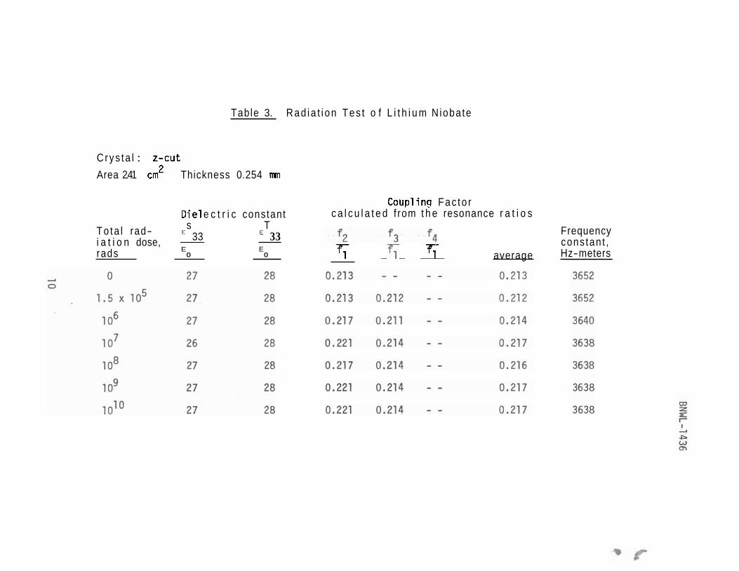
Table 3. Rad ia t i on Tes t o f L i t h i u m N ioba te
C rys ta l : z - cu t
Area 2.41 cm2 Thickness 0.254 mm
Die1 e c t r i c constant
To ta l rad- s T 33 i a t i o n dose, - 33
rads E E 0 0
Coup1 i n g Fac to r c a l c u l a t e d f rom t h e resonance r a t i o s
5 - T - T; average
Frequency cons tan t , Hz-meters

- - 3
Ln
LO
Ln
Ln
hh
W
U
CO
CO
CO
CO
CO
CO
CO
-
Nl rl
WW
WW
WI
DW
Ln
ww
4- e *
LO
W
* *
Wh
X
OO

Table 5. Rad ia t i on Tes t o f L i t h i u m N ioba te
C r y s t a l : x - c u t
Area 1 .39 cm2 Thickness 0.254 mm
Coup1 i n g Fac to r D i e l e c t r i c constant Ca lcu la ted f rom t h e resonance r a t i o s S
T o t a l rad- T €1 1 - - f2 f3 - f4 Frequency - i a t i o n dose, €1 1
€ fl 5- cons t an t , rads o o fl average Hz-meters -

ACKNOWLEDGEMENTS
The author thanks J . C . Harris f o r h is assistance in assembling
and conducting the experimental work. Thanks i s a lso expressed t o
R. L. Brown and Janice Sletager fo r t h e i r help i n preparing t h i s paper.
REFERENCES
A. W . Warner, M. Onoe, G . A. Coquin. "Determination of Elas t ic and
Piezoelectric Constants f o r Crystals i n Class (3M)" J . Acoust. Soc.
Am., Vol. 42, No. 6, December 1967. - M. Onoe, H. F. Tiers ten, A . H. Meitzler. "Shif t i n the Location of
Resonant Frequencies Caused by Large Electromechanical Coupling in
Thickness Mode Resonators ," J . Acoust. Soc. Amer, Vol . 35, No. 1 , January 1963.
W . P. Mason, Hans Ja f fe . "Methods f o r Measuring Piezoelectric,
El a s t i c , and Dielect r ic Coefficients of Crystals and Ceramics ," Proc. IRE, June 1954.
Don Berlincourt. "Measurement of Piezoelectric Coupling i n Odd
Ceramic Shapes," Cl evi t e Technical Paper TP-23, c i rca 1961.
J . P. Arndt. "Procedures fo r Measuring Properties of Piezoelectric
Ceramics ," Clevi t e Technical Paper TP-234, c i rca 1961.
"Standards on Piezoelectric Crystals , 1949," Proc. IRE, Vol. 37
pp. 1 378- 1 395, December 1 949.
"IRE Standards on Piezoelectric Crystals - The Piezoelectric Vibra-
to r : Definitions and Methods of Measurement, 1957 ," Proc. IRE,
Vol. 45, pp. 353-358, March 1957.
"IRE Standards on Piezoelectric Crystals: Determination of the
E las t i c , Piezoelect r ic , and Dielect r ic Constants - The Electro-
mechanical Coup1 ing Factor, 1958," Proc. IRE, Vol . 46, pp. 764-778,
April 1958.
"IRE Standlirds on Piezoelectric Crystals : Measurement of Piezo-
e l e c t r i c Ceramics, 1961 ," Proc. IRE, Vol. 49, pp. 1161-1169,
July 1961.

DISTRIBUTION
No. o f C o p i e s
OFFSITE
1 A E C C h i c a g o P a t e n t Group
G . H. Lee
212 A E C D i v i s i o n o f T e c h n i c a l I n f o r m a t i o n E x t e n s i o n
UC-37
ONSITE
1 A E C C h i c a g o P a t e n t G r o u p
R. K. S h a r p ( R i c h l a n d )
1 AEC R i c h l a n d O p e r a t i o n s O f f i c e
C . L . R o b i n s o n
2 RDT A s s i s t a n t D i r e c t o r o f P a c i f i c N o r t h w e s t P rog rams
3 B a t t e l l e M e m o r i a l I n s t i t u t e
22 B a t t e l l e - N o r t h w e s t
E. R . A s t l e y G. J . Dau ( 1 0 ) N. E . D i x o n 3 . R . S l e t a g e r J. B. V e t r a n o T e c h n i c a l I n f o r m a t i o n F i l e s ( 5 ) T e c h n i c a l P u b l i c a t i o n s ( 2 )
38 WADCO Corp .
F. L . B e c k e r R . L . Brown F. J. L e i t z R. N. O r d H . N. P e d e r s e n R. W . S m i t h ( 2 5 ) W . G . S p e a r C. D . Swanson WADCO Document C o n t r o l ( 5 j W A D C O Tech Pubs ( 7 0 3 )