· electronic advertising contract bids open wednesday, december 19, 2012 dated november 26, 2012...
TRANSCRIPT

Electronic Advertising Contract
Bids open Wednesday, December 19, 2012
Dated November 26, 2012
10
STATE OF CALIFORNIA
DEPARTMENT OF TRANSPORTATION
NOTICE TO BIDDERS AND
SPECIAL PROVISIONS FOR CONSTRUCTION ON STATE HIGHWAY IN SAN JOAQUIN COUNTY AT
VARIOUS LOCATIONS
In District 10 On Route 5, 132, 580
Under
Bid book dated November 26, 2012 Standard Specifications dated 2010
Project plans approved August 27, 2012 Standard Plans dated 2010
Identified by
Contract No. 10-0K3304
10-SJ-5, 132, 580-Var
Project ID 1000000085
Federal-Aid Project
ACNH-X077(019)E


************************************************************************************************************************
SPECIAL NOTICES
************************************************************************************************************************
For federal-aid projects, the Department is modifying its DBE program.


Contract No. 10-0K3304 i
TABLE OF CONTENTS
NOTICE TO BIDDERS ................................................................................................................................. 1
COPY OF BID ITEM LIST ............................................................................................................................ 3
DIVISION I GENERAL PROVISIONS ......................................................................................................... 5
1 GENERAL ................................................................................................................................................. 5
5 CONTROL OF WORK .............................................................................................................................. 5
6 CONTROL OF MATERIALS ..................................................................................................................... 6
7 LEGAL RELATIONS AND RESPONSIBILITY TO THE PUBLIC ............................................................. 6
DIVISION II GENERAL CONSTRUCTION ................................................................................................. 6
12 TEMPORARY TRAFFIC CONTROL ...................................................................................................... 6
14 ENVIRONMENTAL STEWARDSHIP ................................................................................................... 26
15 EXISTING FACILITIES ......................................................................................................................... 28
DIVISION III GRADING ............................................................................................................................. 28
20 LANDSCAPE ........................................................................................................................................ 28
DIVISION VI STRUCTURES ..................................................................................................................... 29
49 PILING .................................................................................................................................................. 29
DIVISION IX TRAFFIC CONTROL FACILITIES ....................................................................................... 32
83 RAILINGS AND BARRIERS ................................................................................................................. 32
86 ELECTRICAL SYSTEMS ..................................................................................................................... 33
REVISED STANDARD SPECIFICATIONS APPLICABLE TO THE 2010 EDITION OF THE STANDARD SPECIFICATIONS ...................................................................................................................................... 51
Contract No. 10-0K3304 ii
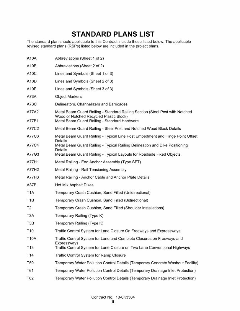
STANDARD PLANS LIST The standard plan sheets applicable to this Contract include those listed below. The applicable revised standard plans (RSPs) listed below are included in the project plans.
A10A Abbreviations (Sheet 1 of 2)
A10B Abbreviations (Sheet 2 of 2)
A10C Lines and Symbols (Sheet 1 of 3)
A10D Lines and Symbols (Sheet 2 of 3)
A10E Lines and Symbols (Sheet 3 of 3)
A73A Object Markers
A73C Delineators, Channelizers and Barricades
A77A2 Metal Beam Guard Railing - Standard Railing Section (Steel Post with Notched Wood or Notched Recycled Plastic Block)
A77B1 Metal Beam Guard Railing - Standard Hardware
A77C2 Metal Beam Guard Railing - Steel Post and Notched Wood Block Details
A77C3 Metal Beam Guard Railing - Typical Line Post Embedment and Hinge Point Offset Details
A77C4 Metal Beam Guard Railing - Typical Railing Delineation and Dike Positioning Details
A77G3 Metal Beam Guard Railing - Typical Layouts for Roadside Fixed Objects
A77H1 Metal Railing - End Anchor Assembly (Type SFT)
A77H2 Metal Railing - Rail Tensioning Assembly
A77H3 Metal Railing - Anchor Cable and Anchor Plate Details
A87B Hot Mix Asphalt Dikes
T1A Temporary Crash Cushion, Sand Filled (Unidirectional)
T1B Temporary Crash Cushion, Sand Filled (Bidirectional)
T2 Temporary Crash Cushion, Sand Filled (Shoulder Installations)
T3A Temporary Railing (Type K)
T3B Temporary Railing (Type K)
T10 Traffic Control System for Lane Closure On Freeways and Expressways
T10A Traffic Control System for Lane and Complete Closures on Freeways and Expressways
T13 Traffic Control System for Lane Closure on Two Lane Conventional Highways
T14 Traffic Control System for Ramp Closure
T59 Temporary Water Pollution Control Details (Temporary Concrete Washout Facility)
T61 Temporary Water Pollution Control Details (Temporary Drainage Inlet Protection)
T62 Temporary Water Pollution Control Details (Temporary Drainage Inlet Protection)

Contract No. 10-0K3304 iii
T63 Temporary Water Pollution Control Details (Temporary Drainage Inlet Protection)
T64 Temporary Water Pollution Control Details (Temporary Drainage Inlet Protection)
T65 Temporary Water Pollution Control Details [Temporary Fence (Type ESA)]
RS1 Roadside Signs, Typical Installation Details No. 1
RS2 Roadside Signs - Wood Post, Typical Installation Details No. 2
RS4 Roadside Signs, Typical Installation Details No. 4
S89 Roadside Sign - Formed Single Sheet Aluminum Panel
S93 Framing Details for Framed Single Sheet Aluminum Signs, Rectangular Shape
S94 Roadside Framed Single Sheet Aluminum Signs, Rectangular Shape
S95 Roadside Single Sheet Aluminum Signs, Diamond Shape
ES-1A Electrical Systems (Legend, Notes and Abbreviations)
ES-1B Electrical Systems (Legend, Notes and Abbreviations)
ES-1C Electrical Systems (Legend, Notes and Abbreviations)
ES-2A Electrical Systems (Service Equipment)
ES-2C Electrical Systems (Service Equipment Notes, Type III Series)
ES-2D Electrical Systems (Service Equipment Enclosure and Typical Wiring Diagram, Type III - A Series)
ES-2F Electrical Systems (Service Equipment Enclosure and Typical Wiring Diagram Type III - C Series)
ES-3C Electrical Systems (Controller Cabinet Foundation Details)
ES-3F Electrical Systems (Telephone Demarcation Cabinet, Type C)
ES-5A Electrical Systems (Detectors)
ES-5B Electrical Systems (Detectors)
ES-5D Electrical Systems (Curb Termination and Handhole)
ES-7M Electrical Systems (Signal and Lighting Standard - Detail No. 1)
RSP ES-8A Electrical Systems (Pull Box)
ES-11 Electrical Systems (Foundation Installations)
ES-13A Electrical Systems (Splicing Details)
ES-16D Electrical Systems (Closed Circuit Television with Vehicle Detection System, 30' to 40' Pole)
Contract No. 10-0K3304 iv
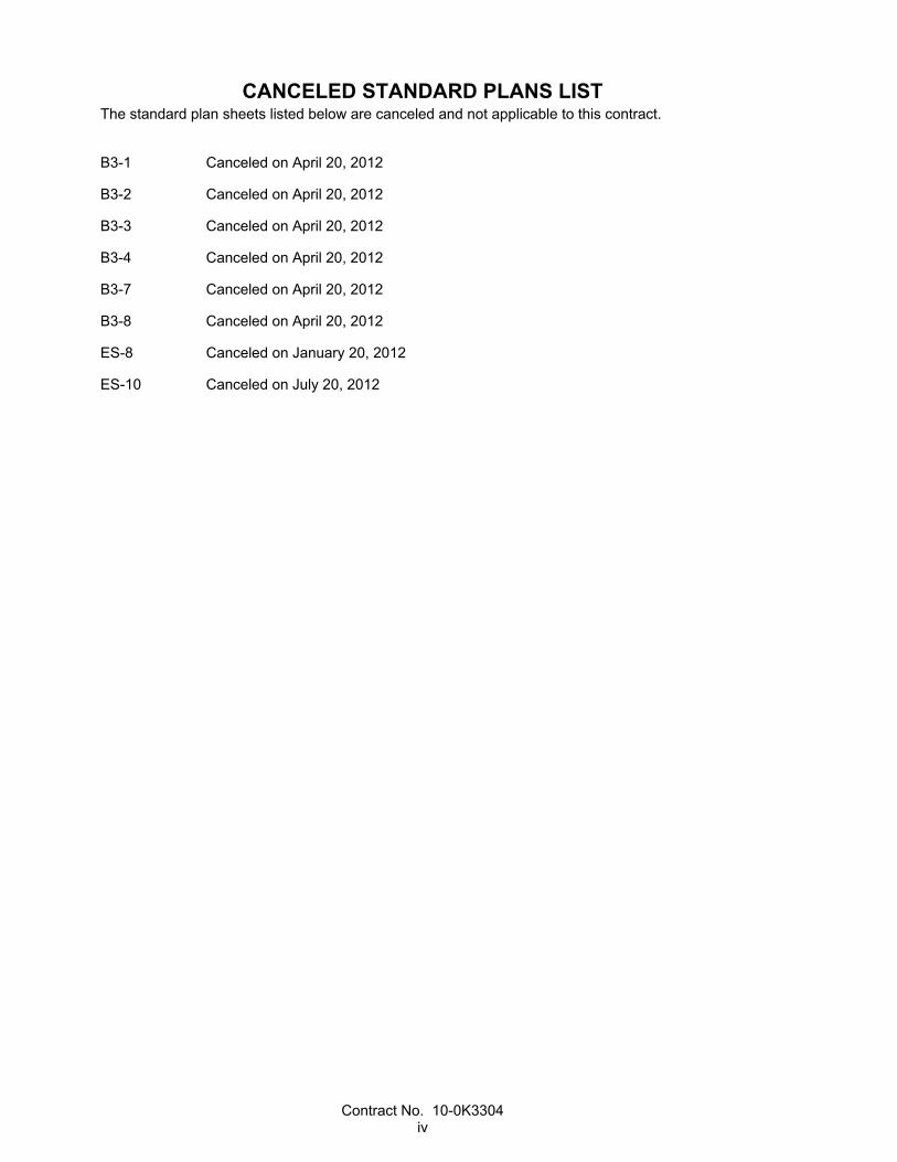
CANCELED STANDARD PLANS LIST The standard plan sheets listed below are canceled and not applicable to this contract.
B3-1 Canceled on April 20, 2012
B3-2 Canceled on April 20, 2012
B3-3 Canceled on April 20, 2012
B3-4 Canceled on April 20, 2012
B3-7 Canceled on April 20, 2012
B3-8 Canceled on April 20, 2012
ES-8 Canceled on January 20, 2012
ES-10 Canceled on July 20, 2012

Contract No. 10-0K3304 1
NOTICE TO BIDDERS
Bids open Wednesday, December 19, 2012
Dated November 26, 2012
General work description: Install traffic monitoring stations (loop detectors) on freeway ramps.
The Department will receive sealed bids for CONSTRUCTION ON STATE HIGHWAY IN SAN JOAQUIN COUNTY AT VARIOUS LOCATIONS.
District-County-Route-Post Mile: 10-SJ-5, 132, 580-Var
Contract No. 10-0K3304
The Contractor must have either a Class A license or one of the following Class C licenses: C-10.
The DBE Contract goal is 7 percent.
Federal-aid project no.:
ACNH-X077(019)E
Bids must be on a unit price basis.
Complete the work within 150 working days.
The estimated cost of the project is $1,630,000.
No prebid meeting is scheduled for this project.
The Department will receive bids until 2:00 p.m. on the bid open date at 1727 30th Street, Bidders' Exchange, MS 26, Sacramento, CA 95816. Bids received after this time will not be accepted. Department staff will direct the bidders to the bid opening.
The Department will open and publicly read the bids at the above location immediately after the specified closing time.
District office addresses are provided in the Standard Specifications.
Present bidders' inquiries to the Department and view the Department's responses at:
http://www.dot.ca.gov/hq/esc/oe/project_status/bid_inq.html
Questions about alleged patent ambiguity of the plans, specifications, or estimate must be asked before bid opening. After bid opening, the Department does not consider these questions as bid protests.
Submit your bid with bidder's security equal to at least 10 percent of the bid.
Prevailing wages are required on this Contract. The Director of the California Department of Industrial Relations determines the general prevailing wage rates. Obtain the wage rates at the DIR Web site, http://www.dir.ca.gov, or from the Department's Labor Compliance Office of the district in which the work is located.
The federal minimum wage rates for this Contract as determined by the United States Secretary of Labor are available at http://www.dot.ca.gov/hq/esc/oe/federal-wages.
If the minimum wage rates as determined by the United States Secretary of Labor differs from the general prevailing wage rates determined by the Director of the California Department of Industrial Relations for similar classifications of labor, the Contractor and subcontractors must not pay less than the higher wage rate. The Department does not accept lower State wage rates not specifically included in the federal minimum wage determinations. This includes helper, or other classifications based on hours of

Contract No. 10-0K3304 2
experience, or any other classification not appearing in the federal wage determinations. Where federal wage determinations do not contain the State wage rate determination otherwise available for use by the Contractor and subcontractors, the Contractor and subcontractors must not pay less than the federal minimum wage rate that most closely approximates the duties of the employees in question.
The Department has made available Notices of Suspension and Proposed Debarment from the Federal Highway Administration. For a copy of the notices, go to http://www.dot.ca.gov/hq/esc/oe/contractor_info. Additional information is provided in the Excluded Parties List System at https://www.epls.gov.
Department of Transportation
LJL

Contract No. 10-0K3304 3
COPY OF BID ITEM LIST
Item No.
Item Code Item Description Unit of Measure Estimated Quantity
1 071325 TEMPORARY FENCE (TYPE ESA) LF 2,650
2 074017 PREPARE WATER POLLUTION CONTROL PROGRAM
LS LUMP SUM
3 074038 TEMPORARY DRAINAGE INLET PROTECTION EA 91
4 120090 CONSTRUCTION AREA SIGNS LS LUMP SUM
5 120100 TRAFFIC CONTROL SYSTEM LS LUMP SUM
6 128651 PORTABLE CHANGEABLE MESSAGE SIGN (EA) EA 4
7 130100 JOB SITE MANAGEMENT LS LUMP SUM
8 130900 TEMPORARY CONCRETE WASHOUT LS LUMP SUM
9 150771 REMOVE ASPHALT CONCRETE DIKE LF 240
10 160102 CLEARING AND GRUBBING (LS) LS LUMP SUM
11 190110 LEAD COMPLIANCE PLAN LS LUMP SUM
12 202011 MULCH CY 74
13 210300 HYDROMULCH SQFT 50,500
14 390136 MINOR HOT MIX ASPHALT TON 2
15 394074 PLACE HOT MIX ASPHALT DIKE (TYPE C) LF 130
16 394077 PLACE HOT MIX ASPHALT DIKE (TYPE F) LF 120
17 820118 GUARD RAILING DELINEATOR EA 9
18 820132 OBJECT MARKER (TYPE L) EA 3
19 832002 METAL BEAM GUARD RAILING (STEEL POST)
LF 100
20 839581 END ANCHOR ASSEMBLY (TYPE SFT) EA 3

Contract No. 10-0K3304 4
Item No.
Item Code Item Description Unit of Measure Estimated Quantity
21 839585 ALTERNATIVE FLARED TERMINAL SYSTEM EA 1
22 860090 MAINTAINING EXISTING TRAFFIC MANAGEMENT SYSTEM ELEMENTS DURING CONSTRUCTION
LS LUMP SUM
23 024872 MODIFY VEHICLE CLASSIFICATION STATION LS LUMP SUM
24 860930 TRAFFIC MONITORING STATION LS LUMP SUM
25 024873 TRAFFIC MONITORING STATION (PHOTOVOLTAIC)
LS LUMP SUM
26 999990 MOBILIZATION LS LUMP SUM

Contract No. 10-0K3304 5
DIVISION I GENERAL PROVISIONS 1 GENERAL
Add to section 1-1.01:
Bid Items and Applicable Sections
Item code
Item description Applicable section
071325 TEMPORARY (TYPE ESA) 14 074017 PREPARE WATER POLLUTION CONTROL PROGRAM 13 074038 TEMPORARY DRAINAGE INLET PROTECTION 13 190110 LEAD COMPLIANCE PLAN 7 024872 MODIFY VEHICLE CLASSIFICATION STATION 86 024873 TRAFFIC MONITORING STATION (PHOTOVOLTAIC) 86
^^^^^^^^^^^^^^^^^^^^^^^^^^^^^^^^^^^^^^^^
5 CONTROL OF WORK
Add to section 5-1.20A:
During the progress of the work under this Contract, work under the following contracts may be in progress at or near the job site of this Contract:
Coincident or Adjacent Contracts
Contract no. County–Route–Post Mile City Type of work 10-0G4704 SJ-5-PM 28.5/35.6 Stockton Widen bridges and
freeway lanes 10-0E4904 SJ-5-PM 22.0/23.6 Stockton Reconstruct
interchanges and add auxiliary lanes
Add to section 5-1.36D:
Utility information is not shown on the project plans. Utility locating (field mark-outs) must be concurrent with construction. Make arrangements with the utility owners to coordinate utility location activities. Mechanically actuated excavation must not be performed within 24-inches (horizontal offset) of subsurface facilities.
^^^^^^^^^^^^^^^^^^^^^^^^^^^^^^^^^^^^^^^^

Contract No. 10-0K3304 6
6 CONTROL OF MATERIALS
Add to section 6-2.03:
The Department furnishes you with:
• Loop detector sensor units • Model 2070E controller units • Central control system, including communication harnesses, antenna cell boosters, and Model
2070-6A modems
The Department furnishes you with a Model 2070E controller unit at 1604 South B Street, Electrical Maintenance, Stockton, CA 95206, (916) 948-7454. At least 48 hours before you pick up the materials, inform the Engineer of what you will pick up and when you will pick it up.
You must furnish replacement plants. The Department does not pay you for the replacement plants.
^^^^^^^^^^^^^^^^^^^^^^^^^^^^^^^^^^^^^^^^
7 LEGAL RELATIONS AND RESPONSIBILITY TO THE PUBLIC
Replace section 7-1.02K(6)(j)(iii) with:
7-1.02K(6)(j)(iii) Earth Material Containing Lead
Section 7-1.02K(6)(j)(iii) includes specifications for handling, removing, and disposing of earth material containing lead.
Submit a lead compliance plan.
Lead is present in earth material on the job site. The average lead concentrations are below 1,000 mg/kg total lead and below 5 mg/L soluble lead. Earth material on the job site:
1. Is not a hazardous waste 2. Does not require disposal at a permitted landfill or solid waste disposal facility
Lead is typically found within the top 2 feet of material in unpaved areas of the highway. Reuse all excavated earth material on the right-of-way.
Handle earth material containing lead under all applicable laws, rules, and regulations, including those of the following agencies:
1. Cal/OSHA 2. CA RWQCB, Region 5S—Central Valley Region 3. CA Department of Toxic Substances Control
^^^^^^^^^^^^^^^^^^^^^^^^^^^^^^^^^^^^^^^^^^^^^^^^^^^^^^^^^^^^
DIVISION II GENERAL CONSTRUCTION 12 TEMPORARY TRAFFIC CONTROL
Add to section 12-3.12C:
Start displaying the message on the portable changeable message sign 15 minutes before closing the lane.

Contract No. 10-0K3304 7
Place 1 portable changeable message sign for each lane closure and one for each ramp or connector closure. The exact locations will be designated by the Engineer.
Replace section 12-3.13 with:
12-3.13 IMPACT ATTENUATOR VEHICLE
12-3.13A General
12-3.13A(1) Summary
Section 12-3.13 includes specifications for protecting traffic and workers with an impact attenuator vehicle during moving lane closures and when placing and removing components of stationary lane closures, ramp closures, shoulder closures, or a combination.
Impact attenuator vehicles must comply with the following test levels under National Cooperative Highway Research Program 350:
1. Test level 3 if the preconstruction posted speed limit is 50 mph or more 2. Test levels 2 or 3 if the preconstruction posted speed limit is 45 mph or less
Comply with the attenuator manufacturer's instructions for:
1. Support truck 2. Trailer-mounted operation 3. Truck-mounted operation
Flashing arrow signs must comply with section 12-3.03. You may use a portable changeable message sign instead of a flashing arrow sign. If a portable changeable message sign is used as a flashing arrow sign, it must comply with section 6F.56 "Arrow Panels" of the California MUTCD.
12-3.13A(2) Definitions
impact attenuator vehicle: A support truck that is towing a deployed attenuator mounted to a trailer or a support truck with a deployed attenuator that is mounted to the support truck.
12-3.13A(3) Submittals
Upon request, submit a certificate of compliance for each attenuator used on the project.
12-3.13A(4) Quality Control and Assurance
Do not start impact attenuator vehicle activities until authorized.
Before starting impact attenuator vehicle activities, conduct a preinstallation meeting with the Engineer, subcontractors, and other parties involved with traffic control to discuss the operation of the impact attenuator vehicle during moving lane closures and when placing and removing components of stationary traffic control systems.
Schedule the location, time, and date for the preinstallation meeting with all participants. Furnish the facility for the preinstallation meeting within 5 miles of the job site or at another location if authorized.
12-3.13B Materials
Attenuators must be a brand on the Authorized Material List for highway safety features.
The combined weight of the support truck and the attenuator must be at least 19,800 pounds, except the weight of the support truck must not be less than 16,100 or greater than 26,400 pounds.
For the Trinity MPS-350 truck–mounted attenuator, the support truck must not have a fuel tank mounted underneath within 10'-6" of the rear of the support truck.
Contract No. 10-0K3304 8
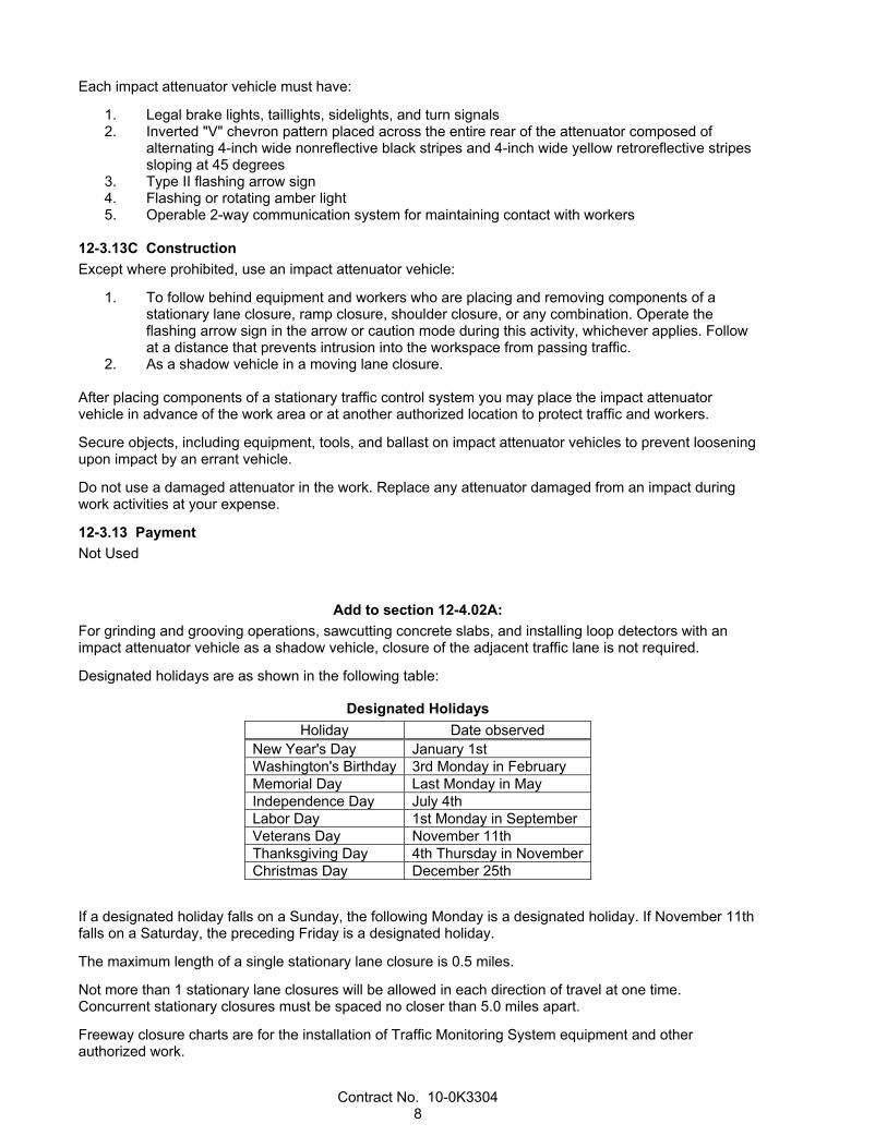
Each impact attenuator vehicle must have:
1. Legal brake lights, taillights, sidelights, and turn signals 2. Inverted "V" chevron pattern placed across the entire rear of the attenuator composed of
alternating 4-inch wide nonreflective black stripes and 4-inch wide yellow retroreflective stripes sloping at 45 degrees
3. Type II flashing arrow sign 4. Flashing or rotating amber light 5. Operable 2-way communication system for maintaining contact with workers
12-3.13C Construction
Except where prohibited, use an impact attenuator vehicle:
1. To follow behind equipment and workers who are placing and removing components of a stationary lane closure, ramp closure, shoulder closure, or any combination. Operate the flashing arrow sign in the arrow or caution mode during this activity, whichever applies. Follow at a distance that prevents intrusion into the workspace from passing traffic.
2. As a shadow vehicle in a moving lane closure.
After placing components of a stationary traffic control system you may place the impact attenuator vehicle in advance of the work area or at another authorized location to protect traffic and workers.
Secure objects, including equipment, tools, and ballast on impact attenuator vehicles to prevent loosening upon impact by an errant vehicle.
Do not use a damaged attenuator in the work. Replace any attenuator damaged from an impact during work activities at your expense.
12-3.13 Payment
Not Used
Add to section 12-4.02A:
For grinding and grooving operations, sawcutting concrete slabs, and installing loop detectors with an impact attenuator vehicle as a shadow vehicle, closure of the adjacent traffic lane is not required.
Designated holidays are as shown in the following table:
Designated Holidays
Holiday Date observed New Year's Day January 1st Washington's Birthday 3rd Monday in February Memorial Day Last Monday in May Independence Day July 4th Labor Day 1st Monday in September Veterans Day November 11th Thanksgiving Day 4th Thursday in NovemberChristmas Day December 25th
If a designated holiday falls on a Sunday, the following Monday is a designated holiday. If November 11th falls on a Saturday, the preceding Friday is a designated holiday.
The maximum length of a single stationary lane closure is 0.5 miles.
Not more than 1 stationary lane closures will be allowed in each direction of travel at one time. Concurrent stationary closures must be spaced no closer than 5.0 miles apart.
Freeway closure charts are for the installation of Traffic Monitoring System equipment and other authorized work.

Contract No. 10-0K3304 9
Personal vehicles of your employees must not be parked on the traveled way or shoulders, including sections closed to traffic.
If work vehicles or equipment are parked within 6 feet of a traffic lane, close the shoulder area as shown.
If a connector closure is required within the limits of a freeway lane closure, complete the work on the connector first. Then, complete the work on the freeway traveled way necessary to ensure safe passage of traffic between the connector and open freeway lanes. Complete the remaining work only after reopening the connector.
Replace "Reserved" in section 12-4.04 with:
Lane Closure Restriction for Designated Holidays and Special Days
Thu Fri Sat Sun Mon Tues Wed Thu Fri Sat Sun x
H xx
xx
xx
SD xx
x
xx
H xx
xx
SD xx
x
xx
H xx
xx
SD xx
x
xx
xx
H xx
xxx
x
xx
xx
SD xx
xxx
x
H xx
x
SD xx
x
H xx
SD xx
x
H xx
xx
xx
xx
SD xx
Legend:
Refer to lane requirement charts x The full width of the traveled way must be open for use by traffic after 6:00 a.m. xx The full width of the traveled way must be open for use by traffic. xxx The full width of the traveled way must be open for use by traffic until 9:00 a.m. H Designated holiday
SD Special day

Contract No. 10-0K3304 10
Replace "Reserved" in section 12-4.05D with:
Chart no. 1 Connector Lane Requirements
County: San Joaquin Route/Direction: 5 Northbound PM: 0.30
Closure limits: Mainline at San Joaquin/Stanislaus County line, off-ramp to westbound Route 580 (Locations 1 and 125).
From hour to hour 24 1 2 3 4 5 6 7 8 9 10 11 12 13 14 151617 18 19 20 21 22 23 24Mondays through Thursdays 1 1 1 1 1 1 1 1 1 1 1 1 1 1 1 1 1 1 1
Fridays 1 1 1 1 1 1 1 1 1 1
Saturdays
Sundays 1 1 1
Legend:
1 Provide at least 1 connector lane open in direction of travel Work allowed within the highway where shoulder or lane closure is not required
REMARKS:
Chart no. 2 Complete Connector Closure Hours
County: San Joaquin Route/Direction: 5 PM: 3.4
Closure limits: Northbound and southbound Route 5 on-ramps and off-ramps to and from eastbound and westbound Route 132 (locations 2-5 and 54-57).
From hour to hour 24 1 2 3 4 5 6 7 8 9 10 11 12 13 14 151617 18 19 20 21 22 23 24Mondays through Thursdays C C C C C C C C
Fridays C C C C C C C
Saturdays
Sundays
Legend: C Connector may be closed completely Work allowed within the highway where shoulder or lane closure is not required
REMARKS: a. Only 1 ramp to be closed at a time at this interchange. b. No 2 consecutive or opposing ramps may be closed at the same time. c. Detour required.

Contract No. 10-0K3304 11
Chart no. 3 Connector Lane Requirements
County: San Joaquin Route/Direction: 5/Northbound PM: R14.8
Closure limits: Off-ramp to eastbound Route 120 (location 14).
From hour to hour 24 1 2 3 4 5 6 7 8 9 10 11 12 13 14 15 16 17 18 19 20 21 22 23 24Mondays through Thursdays 1 1 1 1 1 1 1 1
Fridays 1 1 1 1 1 1
Saturdays
Sundays 1 1
Legend:
1 Provide at least 1 connector lane open in direction of travel Work allowed within the highway where shoulder or lane closure is not required
REMARKS:
Chart no. 4 Complete Connector Closure Hours
County: San Joaquin Route/Direction: 5/Northbound PM: R14.8
Closure limits: On-ramp from westbound Route 120 (location 15).
From hour to hour 24 1 2 3 4 5 6 7 8 9 10 11 12 13 14 15 16 17 18 19 20 21 22 23 24Mondays through Thursdays C C C C C C C C
Fridays C C C C
Saturdays
Sundays C C C C
Legend: C Connector may be closed completely Work allowed within the highway where shoulder or lane closure is not required
REMARKS: a. No 2 consecutive or opposing ramps may be closed at the same time. b. Detour required.

Contract No. 10-0K3304 12
Chart no. 5 Connector Lane Requirements
County: San Joaquin Route/Direction: 5/Northbound PM: 25.7
Closure limits: Off-ramp to eastbound Route 4 (location 33).
From hour to hour 24 1 2 3 4 5 6 7 8 9 10 11 12 13 14 151617 18 19 20 21 22 23 24Mondays through Thursdays 1 1 1 1 1 1 1 1
Fridays 1 1 1 1 1
Saturdays
Sundays 1 1 1
Legend:
1 Provide at least 1 connector lane open in direction of travel Work allowed within the highway where shoulder or lane closure is not required
REMARKS:
Chart no. 6 Connector Lane Requirements
County: San Joaquin Route/Direction: 5/Northbound PM: 25.7
Closure limits: Off-ramp to westbound Route 4 (location 34).
From hour to hour 24 1 2 3 4 5 6 7 8 9 10 11 12 13 14 151617 18 19 20 21 22 23 24Mondays through Thursdays 1 1 1 1 1 1 1 1 1
Fridays 1 1 1 1 1 1
Saturdays
Sundays 1 1 1
Legend:
1 Provide at least 1 connector lane open in direction of travel Work allowed within the highway where shoulder or lane closure is not required
REMARKS:

Contract No. 10-0K3304 13
Chart no. 7 Complete Connector Closure Hours
County: San Joaquin Route/Direction: 5/Northbound PM: 25.9
Closure limits: On-ramp from eastbound Route 4 (location 35).
From hour to hour 24 1 2 3 4 5 6 7 8 9 10 11 12 13 14 15 16 17 18 19 20 21 22 23 24Mondays through Thursdays C C C C C C C C
Fridays C C C C C
Saturdays
Sundays C C C
Legend: C Connector may be closed completely Work allowed within the highway where shoulder or lane closure is not required
REMARKS: a. No 2 consecutive or opposing ramps may be closed at the same time. b. Detour required.
Chart no. 8 Complete Connector Closure Hours
County: San Joaquin Route/Direction: 5/Northbound PM: 25.9
Closure limits: On-ramp from westbound Route 4 (location 36).
From hour to hour 24 1 2 3 4 5 6 7 8 9 10 11 12 13 14 15 16 17 18 19 20 21 22 23 24Mondays through Thursdays C C C C C C C
Fridays C C C C
Saturdays
Sundays C C C
Legend: C Connector may be closed completely Work allowed within the highway where shoulder or lane closure is not required
REMARKS: a. No 2 consecutive or opposing ramps may be closed at the same time. b. Detour required.

Contract No. 10-0K3304 14
Chart no. 9 Connector Lane Requirements
County: San Joaquin Route/Direction: 5/Northbound PM: 39.6
Closure limits: Off-ramp to Route 12 (location 45).
From hour to hour 24 1 2 3 4 5 6 7 8 9 10 11 12 13 14 151617 18 19 20 21 22 23 24Mondays through Thursdays 1 1 1 1 1 1 1 1
Fridays 1 1 1 1 1
Saturdays
Sundays 1 1 1
Legend:
1 Provide at least 1 connector lane open in direction of travel Work allowed within the highway where shoulder or lane closure is not required
REMARKS:
Chart no. 10 Complete Connector Closure Hours
County: San Joaquin Route/Direction: 5 PM: 39.6
Closure limits: Northbound Route 5: on-ramp from Route 12 (location 46). Southbound Route 5: on-ramp from eastbound Route 12, on-ramp from westbound Route 12, off-ramp to Route 12 (locations 97-99).
From hour to hour 24 1 2 3 4 5 6 7 8 9 10 11 12 13 14 151617 18 19 20 21 22 23 24Mondays through Thursdays C C C C C C C C
Fridays C C C C C
Saturdays
Sundays C C C
Legend: C Connector may be closed completely Work allowed within the highway where shoulder or lane closure is not required
REMARKS: a. No 2 consecutive or opposing ramps may be closed at the same time. b. Detour required. c. Closure of local roads will require city or county concurrence.

Contract No. 10-0K3304 15
Chart no. 11 Connector Lane Requirements
County: San Joaquin Route/Direction: 5/Southbound PM: 0.3
Closure limits: Mainline at San Joaquin/Stanislaus county line, on-ramp from eastbound Route 580 (locations 53 and 126).
From hour to hour 24 1 2 3 4 5 6 7 8 9 10 11 12 13 14 15 16 17 18 19 20 21 22 23 24Mondays through Thursdays 1 1 1 1 1 1 1 1 1
Fridays 1 1 1 1 1 1 1 1 1
Saturdays
Sundays
Legend:
1 Provide at least 1 connector lane open in direction of travel Work allowed within the highway where shoulder or lane closure is not required
REMARKS:
Chart no. 12 Connector Lane Requirements
County: San Joaquin Route/Direction: 5/Southbound PM: R14.8
Closure limits: On-ramp from westbound Route 120 (location 66).
From hour to hour 24 1 2 3 4 5 6 7 8 9 10 11 12 13 14 15 16 17 18 19 20 21 22 23 24Mondays through Thursdays 1 1 1 1 1 1 1 1
Fridays 1 1 1 1
Saturdays
Sundays 1 1 1
Legend:
1 Provide at least 1 connector lane open in direction of travel Work allowed within the highway where shoulder or lane closure is not required
REMARKS:

Contract No. 10-0K3304 16
Chart no. 13 Complete Connector Closure Hours
County: San Joaquin Route/Direction: 5/Southbound PM: R14.8
Closure limits: Off-ramp to eastbound Route 120 (location 67).
From hour to hour 24 1 2 3 4 5 6 7 8 9 10 11 12 13 14 151617 18 19 20 21 22 23 24Mondays through Thursdays C C C C C C C C
Fridays C C C C C
Saturdays
Sundays C C C
Legend: C Connector may be closed completely Work allowed within the highway where shoulder or lane closure is not required
REMARKS: a. No 2 consecutive or opposing ramps may be closed at the same time. b. Detour required.
Chart no. 14 Complete Connector Closure Hours
County: San Joaquin Route/Direction: 5/Southbound PM: 25.9
Closure limits: On-ramp from eastbound Route 4 (location 85).
From hour to hour 24 1 2 3 4 5 6 7 8 9 10 11 12 13 14 151617 18 19 20 21 22 23 24Mondays through Thursdays C C C C C C C C C
Fridays C C C C C
Saturdays
Sundays C C C
Legend: C Connector may be closed completely Work allowed within the highway where shoulder or lane closure is not required
REMARKS: a. No 2 consecutive or opposing ramps may be closed at the same time. b. Detour required.

Contract No. 10-0K3304 17
Chart no. 15 Complete Connector Closure Hours
County: San Joaquin Route/Direction: 5/Southbound PM: 25.9
Closure limits: On-ramp from westbound Route 4 (location 86).
From hour to hour 24 1 2 3 4 5 6 7 8 9 10 11 12 13 14 15 16 17 18 19 20 21 22 23 24Mondays through Thursdays C C C C C C C
Fridays C C C C
Saturdays
Sundays C C C
Legend: C Connector may be closed completely Work allowed within the highway where shoulder or lane closure is not required
REMARKS: a. No 2 consecutive or opposing ramps may be closed at the same time. b. Detour required.
Chart no. 16 Complete Connector Closure Hours/Connector Lane Requirements
County: San Joaquin Route/Direction: 5/Southbound PM: 26.2
Closure limits: Off-ramp to eastbound Route 4 (location 87).
From hour to hour 24 1 2 3 4 5 6 7 8 9 10 11 12 13 14 15 16 17 18 19 20 21 22 23 24Mondays through Thursdays C C C C 1 1 1 C C
Fridays C C C C 1
Saturdays
Sundays 1 C C
Legend:
1 Provide at least 1 connector lane open in direction of travel
C Connector may be closed completely Work allowed within the highway where shoulder or lane closure is not required
REMARKS: a. No 2 consecutive or opposing ramps may be closed at the same time. b. Detour required.

Contract No. 10-0K3304 18
Chart no. 17 Connector Lane Requirements
County: San Joaquin Route/Direction: 132/Eastbound PM: 0.2
Closure limits: On-ramp from eastbound Route 580 (location 114).
From hour to hour 24 1 2 3 4 5 6 7 8 9 10 11 12 13 14 151617 18 19 20 21 22 23 24Mondays through Thursdays 1 1 1 1 1 1 1 1
Fridays 1 1 1 1 1 1 1 1
Saturdays
Sundays
Legend:
1 Provide at least 1 connector lane open in direction of travel Work allowed within the highway where shoulder or lane closure is not required
REMARKS: a. No 2 consecutive or opposing ramps may be closed at the same time. b. Detour required.
Chart no. 18 Connector Lane Requirements
County: San Joaquin Route/Direction: 132/Westbound
PM: 0.2
Closure limits: Off-ramp to westbound Route 580 (location 120).
From hour to hour 24 1 2 3 4 5 6 7 8 9 10 11 12 13 14 151617 18 19 20 21 22 23 24Mondays through Thursdays 1 1 1 1 1 S S S S S S S S 1 1 1 1 1
Fridays 1 1 1 1 1 S S S S S S S S
Saturdays
Sundays 1 1 1 1 1
Legend:
1 Provide at least 1 connector lane open in direction of travel
S Shoulder closure allowed Work allowed within the highway where shoulder or lane closure is not required
REMARKS: a. No 2 consecutive or opposing ramps may be closed at the same time. b. Detour required.

Contract No. 10-0K3304 19
Replace "Reserved" in section 12-4.05E with:
Chart no. 19 Complete Ramp Closure Hours
County: San Joaquin Route/Direction: 5/Northbound PM: Various
Closure limits: Off-ramp to Route 33, on-ramp from Route 33, off-ramp to Kasson Road; on-ramp from Kasson Road, off-ramp to Louise Avenue, on-ramp from Louise Avenue, off-ramp to Lathrop Road, on-ramp from Lathrop Road, off-ramp to Roth Road, on-ramp from Roth Road, off-ramp to El Dorado Street, off-ramp to Mathews Road, on-ramp from Mathews Road, off-ramp to Downing Avenue, on-ramp from Downing Avenue, off-ramp to 8th Street, on-ramp from 8th Street, off-ramp to Turner Road, on-ramp from Turner Road, off-ramp to Peltier Road, on-ramp from Peltier Road, off-ramp to Walnut Grove Road, on-ramp from Walnut Grove Road (locations 6-9, 16-24, 27-30, and 47-52).
From hour to hour 24 1 2 3 4 5 6 7 8 9 10 11 12 13 14 15 16 17 18 19 20 21 22 23 24Mondays through Thursdays C C C C C C C C
Fridays C C C C C C C
Saturdays
Sundays
Legend: C Ramp may be closed completely Work allowed within the highway where shoulder or lane closure is not required
REMARKS: a. No 2 consecutive or opposing ramps may be closed at the same time. b. Detour required. c. Closures of local roads will require city or county concurrence.

Contract No. 10-0K3304 20
Replace "Reserved" in section 12-4.05E with:
Chart no. 20 Complete Ramp Closure Hours
County: San Joaquin Route/Direction: 5/Northbound PM: Various
Closure limits: On-ramp from 11th Street, off-ramp to Mossdale Road, on-ramp from Mossdale Road, off-ramp to Charter Way(Route 4), on-ramp from Charter Way(Route 4), off-ramp to Pershing Avenue, on-ramp from Pershing Avenue, off-ramp to Monte Diablo Avenue, on-ramp from Monte Diablo Avenue, off-ramp to Country Club Boulevard, on-ramp from Alpine Avenue, off-ramp to Eight Mile Road, on-ramp from Eight Mile Road (locations 10, 12, 13, 31, 32, and 37-44).
From hour to hour 24 1 2 3 4 5 6 7 8 9 10 11 12 13 14 151617 18 19 20 21 22 23 24Mondays through Thursdays C C C C C C C C
Fridays C C C C C
Saturdays
Sundays C C C
Legend: C Ramp may be closed completely Work allowed within the highway where shoulder or lane closure is not required
REMARKS: a. No 2 consecutive or opposing ramps may be closed at the same time. b. Detour required. c. Closures of local roads will require city or county concurrence.
Contract No. 10-0K3304 21
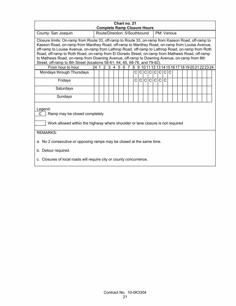
Chart no. 21 Complete Ramp Closure Hours
County: San Joaquin Route/Direction: 5/Southbound PM: Various
Closure limits: On-ramp from Route 33, off-ramp to Route 33, on-ramp from Kasson Road, off-ramp to Kasson Road, on-ramp from Manthey Road, off-ramp to Manthey Road, on-ramp from Louise Avenue, off-ramp to Louise Avenue, on-ramp from Lathrop Road, off-ramp to Lathrop Road, on-ramp from Roth Road, off-ramp to Roth Road, on-ramp from El Dorado Street, on-ramp from Mathews Road, off-ramp to Mathews Road, on-ramp from Downing Avenue, off-ramp to Downing Avenue, on-ramp from 8th Street, off-ramp to 8th Street (locations 58-61, 64, 65, 68-76, and 79-82).
From hour to hour 24 1 2 3 4 5 6 7 8 9 10 11 12 13 14 15 16 17 18 19 20 21 22 23 24Mondays through Thursdays C C C C C C C C
Fridays C C C C C C C
Saturdays
Sundays
Legend: C Ramp may be closed completely Work allowed within the highway where shoulder or lane closure is not required
REMARKS: a. No 2 consecutive or opposing ramps may be closed at the same time. b. Detour required. c. Closures of local roads will require city or county concurrence.

Contract No. 10-0K3304 22
Chart no. 22 Complete Ramp Closure Hours
County: San Joaquin Route/Direction: 5/Southbound 580/eastbound and westbound
PM: Various
Closure limits: Southbound Route 5: Off-ramp to Tracy at 11th Street, on-ramp from Fremont Street, off-ramp to Fremont Street, on-ramp from Monte Diablo Avenue, off-ramp to Monte Diablo Avenue, on-ramp from Country Club Boulevard, off-ramp to Alpine Avenue, on-ramp from Eight Mile Road, off-ramp to Eight Mile Road (locations 62 and 89-96). Eastbound and westbound Route 580 on-ramps and off-ramps to and from Patterson Pass Road (locations 117, 118, 123, and 124).
From hour to hour 24 1 2 3 4 5 6 7 8 9 10 11 12 13 14 151617 18 19 20 21 22 23 24Mondays through Thursdays C C C C C C C C
Fridays C C C C
Saturdays
Sundays C C C C
Legend: C Ramp may be closed completely Work allowed within the highway where shoulder or lane closure is not required
REMARKS: a. No 2 consecutive or opposing ramps may be closed at the same time. b. Detour required. c. Closures of local roads will require city or county concurrence.
Chart no. 23 Complete Ramp Closure Hours
County: San Joaquin Route/Direction: 5/Southbound PM: 25.4
Closure limits: On-ramp from Charter Way/Route 4, off-ramp to Charter Way(Route 4), (locations 83 and 84).
From hour to hour 24 1 2 3 4 5 6 7 8 9 10 11 12 13 14 151617 18 19 20 21 22 23 24Mondays through Thursdays C C C C C C C C
Fridays C C C C C
Saturdays
Sundays C C C
Legend: C Ramp may be closed completely Work allowed within the highway where shoulder or lane closure is not required
REMARKS: a. No 2 consecutive or opposing ramps may be closed at the same time. b. Detour required. c. Closures of local roads will require city or county concurrence.

Contract No. 10-0K3304 23
Chart no. 24 Complete Ramp Closure Hours
County: San Joaquin Route/Direction: 5/Southbound, 132 eastbound and westbound
PM: Various
Closure limits: Southbound Route 5: on-ramp from Turner Road, off-ramp to Turner Road, on-from Peltier Road, off-ramp to Peltier Road, on-ramp from Walnut Grove Road, off-ramp to Walnut Grove Road (locations 100-105). Eastbound and westbound Route 132 on-ramps and off-ramps to and from Chrisman Road (locations 106, 107, 110, and 111).
From hour to hour 24 1 2 3 4 5 6 7 8 9 10 11 12 13 14 15 16 17 18 19 20 21 22 23 24Mondays through Thursdays C C C C C C C C
Fridays C C C C C C
Saturdays
Sundays
Legend: C Ramp may be closed completely Work allowed within the highway where shoulder or lane closure is not required
REMARKS: a. No 2 consecutive or opposing ramps may be closed at the same time. b. Detour required. c. Closures of local roads will require city or cCounty concurrence.

Contract No. 10-0K3304 24
Chart no. 25 Complete Ramp Closure Hours
County: San Joaquin Route/Direction: 132/Eastbound and westbound
PM: T6.0
Closure limits: Eastbound and westbound Route 132 on-ramps and off-ramps to and from Route 33 (locations 109 and 127-129).
From hour to hour 24 1 2 3 4 5 6 7 8 9 10 11 12 13 14 151617 18 19 20 21 22 23 24Mondays through Thursdays S C C C C C C C S S
Fridays S C C C C C C C
Saturdays
Sundays
Legend: C Ramp may be closed completely
S Shoulder closure allowed Work allowed within the highway where shoulder or lane closure is not required
REMARKS: a. Eastbound and westbound Route 132 Off-ramps to Route 33 may be closed at the same time, use on-ramp from Route 33 for traffic detour. b. On-ramp from Route 33 may be closed, use eastbound Route 132 off-ramp to Route 33 for traffic detour. c. Westbound Route 132 off-ramp to Route 33 may be closed, use eastbound Route 132 off-ramp to Route 33 for traffic detour. d. Flagger and channelizers required. e. No 2 consecutive or opposing ramps may be closed at the same time. f. Closures of local roads will require City or cCounty concurrence.

Contract No. 10-0K3304 25
Chart no. 26 Complete Ramp Closure Hours
County: San Joaquin Route/Direction: 580/Eastbound and westbound
PM: 4.0, 8.1
Closure limits: Eastbound Route 580: on-ramp from Chrisman Road, on-ramp from Corral Hollow Road, off-ramp to Corral Hollow Road (locations 113, 115, and 116). Westbound Route 580: off-ramp to Chrisman Road, off-ramp to Corral Hollow Road, on-ramp from Corral Hollow Road (locations 119, 121, 122).
From hour to hour 24 1 2 3 4 5 6 7 8 9 10 11 12 13 14 15 16 17 18 19 20 21 22 23 24Mondays through Thursdays C C C C C C C C
Fridays C C C C C C C
Saturdays
Sundays
Legend: C Ramp may be closed completely Work allowed within the highway where shoulder or lane closure is not required
REMARKS: a. No 2 consecutive or opposing ramps may be closed at the same time. b. Detour required. c. Closures of local roads will require city or county concurrence.
Replace section 12-5 with:
12-5 TRAFFIC CONTROL SYSTEM FOR LANE CLOSURE
12-5.01 GENERAL
Section 12-5 includes specifications for closing traffic lanes, ramps, or a combination, with stationary lane closures on multilane highways. The traffic control system for a lane closure or a ramp closure must comply with the details shown.
Traffic control system includes signs.
12-5.02 MATERIALS
Not Used
12-5.03 CONSTRUCTION
Each vehicle used to place, maintain, and remove components of a traffic control system on a multilane highway must be equipped with a Type II flashing arrow sign that must be in operation whenever the vehicle is being used for placing, maintaining, or removing the components. Vehicles equipped with a Type II flashing arrow sign not involved in placing, maintaining, or removing the components if operated within a stationary-type lane closure must display only the caution display mode. The sign must be controllable by the operator of the vehicle while the vehicle is in motion. If a flashing arrow sign is required for a lane closure, the flashing arrow sign must be operational before the lane closure is in place.
Whenever components of the traffic control system are displaced or cease to operate or function as specified from any cause, immediately repair the components to the original condition or replace the components and restore the components to the original location.

Contract No. 10-0K3304 26
For a stationary lane closure, ramp closure, or a combination, made only for the work period, remove the components of the traffic control system from the traveled way and shoulder, except for portable delineators placed along open trenches or excavation adjacent to the traveled way at the end of each work period. You may store the components at selected central locations designated by the Engineer within the limits of the highway.
12-5.04 PAYMENT
Traffic control system for lane closure is paid for as traffic control system. Flagging costs are paid for as specified in section 12-1.03.
The requirements in section 4-1.05 for payment adjustment do not apply to traffic control system. Adjustments in compensation for traffic control system will be made for an increase or decrease in traffic control work if ordered and will be made on the basis of the cost of the necessary increased or decreased traffic control. The adjustment will be made on a force account basis for increased work and estimated on the same basis in the case of decreased work.
A traffic control system required by change order work is paid for as a part of the change order work.
^^^^^^^^^^^^^^^^^^^^^^^^^^^^^^^^^^^^^^^^
14 ENVIRONMENTAL STEWARDSHIP
Add to section 14-1.02:
An ESA exists on this project.
Before start of work, protect the ESA by installing Temporary Fence (Type ESA).
Replace section 14-6.02 with:
14-6.02 SPECIES PROTECTION
14-6.02A General
Section 14-6.02 includes specifications for protecting regulated species or their habitat.
This project is within or near habitat for regulated species shown in the following table:
Species Name
Giant garter snake (GGS) California tiger salamander (CTS) Swainson's hawk Riparian brush rabbit San Joaquin kit fox
14-6.02B Material
Not Used
14-6.02C Construction
14-6.02C(1) General
Not Used
Contract No. 10-0K3304 27
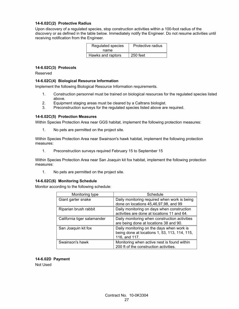
14-6.02C(2) Protective Radius
Upon discovery of a regulated species, stop construction activities within a 100-foot radius of the discovery or as defined in the table below. Immediately notify the Engineer. Do not resume activities until receiving notification from the Engineer.
Regulated species name
Protective radius
Hawks and raptors 250 feet
14-6.02C(3) Protocols
Reserved
14-6.02C(4) Biological Resource Information
Implement the following Biological Resource Information requirements.
1. Construction personnel must be trained on biological resources for the regulated species listed above.
2. Equipment staging areas must be cleared by a Caltrans biologist. 3. Preconstruction surveys for the regulated species listed above are required.
14-6.02C(5) Protection Measures
Within Species Protection Area near GGS habitat, implement the following protection measures:
1. No pets are permitted on the project site.
Within Species Protection Area near Swainson's hawk habitat, implement the following protection measures:
1. Preconstruction surveys required February 15 to September 15
Within Species Protection Area near San Joaquin kit fox habitat, implement the following protection measures:
1. No pets are permitted on the project site.
14-6.02C(6) Monitoring Schedule
Monitor according to the following schedule:
Monitoring type Schedule Giant garter snake Daily monitoring required when work is being
done on locations 45,46,97,98, and 99 Riparian brush rabbit Daily monitoring on days when construction
activities are done at locations 11 and 64. California tiger salamander Daily monitoring when construction activities
are being done at locations 38 and 90. San Joaquin kit fox Daily monitoring on the days when work is
being done at locations 1, 53, 113, 114, 115, 116, and 117.
Swainson's hawk Monitoring when active nest is found within 200 ft of the construction activities.
14-6.02D Payment
Not Used

Contract No. 10-0K3304 28
^^^^^^^^^^^^^^^^^^^^^^^^^^^^^^^^^^^^^^^^
15 EXISTING FACILITIES
Replace section 15-2.02F with:
15-2.02F Remove Asphalt Concrete Dikes
Before removing the dike, cut the outside edge of the asphalt concrete on a neat line and to a minimum depth of 0.17 foot.
Replace section 15-2.03A(2)(b) with:
15-2.03A(2)(b) Department Salvage Location
A minimum of 2 business days before hauling salvaged material to the Department salvage storage location, notify:
1. Engineer
The salvage storage location is:
1604 South B Street Stockton, CA 95206
Replace section 15-2.03A(4) with:
15-2.03A(4) Payment
Payment for salvaging electrical materials is included in the payment for traffic monitoring station.
^^^^^^^^^^^^^^^^^^^^^^^^^^^^^^^^^^^^^^^^^^^^^^^^^^^^^^^^^^^^
DIVISION III GRADING 20 LANDSCAPE
Replace section 20-3.03C(1)(c) with:
20-3.03C(1)(c) Directional Boring
Notify the Engineer 2 working days before starting directional bore operations. Perform directional bore operations in the presence of the Engineer.
Conduits installed by the directional bore method must be PVC Schedule 40 and comply with section 20-3.02M(3)(a).
The diameter of the boring tool for directional boring must be only as large as necessary to install conduit. Only use mineral slurry or wetting solution to lubricate the boring tool and to stabilize the soil surrounding the boring path. Mineral slurry or wetting solution must be water based and environmentally safe.
Dispose of residue from directional boring operations.
The direction bore equipment must have directional control of the boring tool and an electronic boring tool location detection system. During operation the directional bore equipment must be able to determine the location of the tool both horizontally and vertically.
You must have direct charge and control of the directional bore operation at all times.
Contract No. 10-0K3304 29
^^^^^^^^^^^^^^^^^^^^^^^^^^^^^^^^^^^^^^^^^^^^^^^^^^^^^^^^^^^^
DIVISION VI STRUCTURES 49 PILING
Replace"Reserved" in section 49-3.02A(4)(b) with:
Schedule and hold a preconstruction meeting for CIDH concrete pile construction (1) at least 5 business days after submitting the pile installation plan and (2) at least 10 days before the start of CIDH concrete pile construction. You must provide a facility for the meeting.
The meeting must include the Engineer, your representatives, and any subcontractors involved in CIDH concrete pile construction.
The purpose of this meeting is to:
1. Establish contacts and communication protocol between you and your representatives, any subcontractors, and the Engineer
2. Review the construction process, acceptance testing, and anomaly mitigation of CIDH concrete piles
The Engineer will conduct the meeting. Be prepared to discuss the following:
1. Pile placement plan, dry and wet 2. Acceptance testing, including gamma-gamma logging, cross-hole sonic logging, and coring 3. Pile Design Data Form 4. Mitigation process 5. Timeline and critical path activities 6. Structural, geotechnical, and corrosion design requirements 7. Future meetings, if necessary, for pile mitigation and pile mitigation plan review 8. Safety requirements, including Cal/OSHA and Tunnel Safety Orders
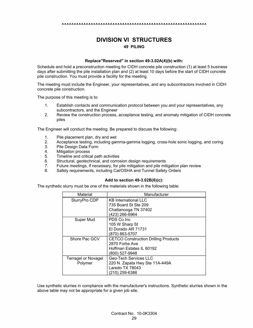
Add to section 49-3.02B(6)(c):
The synthetic slurry must be one of the materials shown in the following table:
Material Manufacturer SlurryPro CDP KB International LLC
735 Board St Ste 209 Chattanooga TN 37402 (423) 266-6964
Super Mud PDS Co Inc 105 W Sharp St El Dorado AR 71731 (870) 863-5707
Shore Pac GCV CETCO Construction Drilling Products 2870 Forbs Ave Hoffman Estates IL 60192 (800) 527-9948
Terragel or Novagel Polymer
Geo-Tech Services LLC 220 N. Zapata Hwy Ste 11A-449A Laredo TX 78043 (210) 259-6386
Use synthetic slurries in compliance with the manufacturer's instructions. Synthetic slurries shown in the above table may not be appropriate for a given job site.
Contract No. 10-0K3304 30
Synthetic slurries must comply with the Department's requirements for synthetic slurries to be included in the above table. The requirements are available from the Offices of Structure Design, P.O. Box 168041, MS# 9-4/11G, Sacramento, CA 95816-8041.
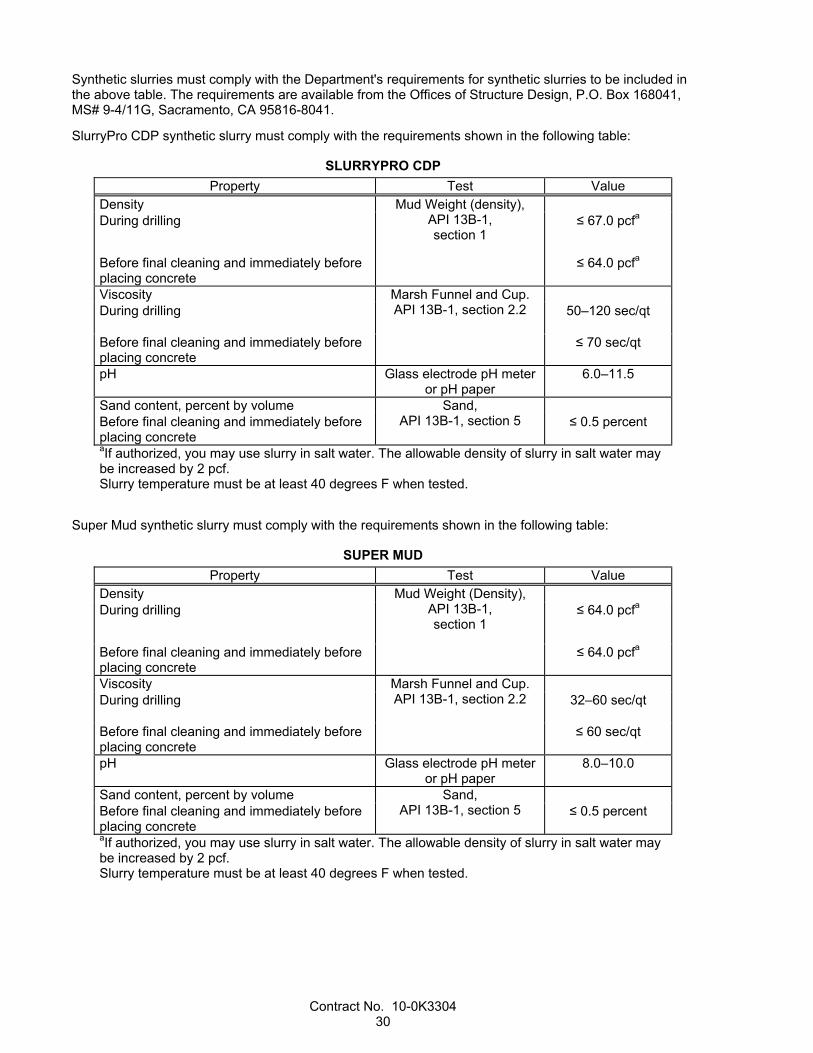
SlurryPro CDP synthetic slurry must comply with the requirements shown in the following table:
SLURRYPRO CDP
Property Test Value Density Mud Weight (density),
API 13B-1, section 1
During drilling
≤ 67.0 pcfa
Before final cleaning and immediately before placing concrete
≤ 64.0 pcfa
Viscosity Marsh Funnel and Cup. API 13B-1, section 2.2
During drilling 50–120 sec/qt
Before final cleaning and immediately before placing concrete
≤ 70 sec/qt
pH Glass electrode pH meter or pH paper
6.0–11.5
Sand content, percent by volume Sand, API 13B-1, section 5
Before final cleaning and immediately before placing concrete
≤ 0.5 percent
aIf authorized, you may use slurry in salt water. The allowable density of slurry in salt water may be increased by 2 pcf. Slurry temperature must be at least 40 degrees F when tested.
Super Mud synthetic slurry must comply with the requirements shown in the following table:
SUPER MUD
Property Test Value Density Mud Weight (Density),
API 13B-1, section 1
During drilling
≤ 64.0 pcfa
Before final cleaning and immediately before placing concrete
≤ 64.0 pcfa
Viscosity Marsh Funnel and Cup. API 13B-1, section 2.2
During drilling 32–60 sec/qt
Before final cleaning and immediately before placing concrete
≤ 60 sec/qt
pH Glass electrode pH meter or pH paper
8.0–10.0
Sand content, percent by volume Sand, API 13B-1, section 5
Before final cleaning and immediately before placing concrete
≤ 0.5 percent
aIf authorized, you may use slurry in salt water. The allowable density of slurry in salt water may be increased by 2 pcf. Slurry temperature must be at least 40 degrees F when tested.

Contract No. 10-0K3304 31
Shore Pac GCV synthetic slurry must comply with the requirements shown in the following table:
SHORE PAC GCV
Property Test Value Density Mud Weight (Density),
API 13B-1, section 1
During drilling
≤ 64.0 pcfa
Before final cleaning and immediately before placing concrete
≤ 64.0 pcfa
Viscosity Marsh Funnel and Cup. API 13B-1, section 2.2
During drilling 33–74 sec/qt
Before final cleaning and immediately before placing concrete
≤ 57 sec/qt
pH Glass electrode pH meter or pH paper
8.0–11.0
Sand content, percent by volume Sand, API 13B-1, section 5
Before final cleaning and immediately before placing concrete
≤ 0.5 percent
aIf authorized, you may use slurry in salt water. The allowable density of slurry in salt water may be increased by 2 pcf. Slurry temperature must be at least 40 degrees F when tested.
Terragel or Novagel Polymer synthetic slurry must comply with the requirements shown in the following table:
TERRAGEL OR NOVAGEL POLYMER
Property Test Value Density Mud Weight (Density),
API 13B-1, section 1
During drilling
≤ 67.0 pcfa
Before final cleaning and immediately before placing concrete
≤ 64.0 pcfa
Viscosity Marsh Funnel and Cup. API 13B-1, section 2.2
During drilling 45–104 sec/qt
Before final cleaning and immediately before placing concrete
≤ 104 sec/qt
pH Glass electrode pH meter or pH paper
6.0–11.5
Sand content, percent by volume Sand, API 13B-1, section 5
Before final cleaning and immediately before placing concrete
≤ 0.5 percent
aIf authorized, you may use slurry in salt water. The allowable density of slurry in salt water may be increased by 2 pcf. Slurry temperature must be at least 40 degrees F when tested.
^^^^^^^^^^^^^^^^^^^^^^^^^^^^^^^^^^^^^^^^^^^^^^^^^^^^^^^^^^^^

Contract No. 10-0K3304 32
DIVISION IX TRAFFIC CONTROL FACILITIES 83 RAILINGS AND BARRIERS
Replace item 1 in the 7th paragraph of section 83-1.02B with:
1. Wood, Steel, or plastic posts
Replace item 2 in the 7th paragraph of section 83-1.02B with:
2. Plastic blocks for line posts
Replace section 83-1.02C(3) with:
83-1.02C(3) Alternative Flared Terminal System
Alternative flared terminal system must be furnished and installed as shown on the plans and under these special provisions.
The allowable alternatives for a flared terminal system must consist of one of the following or a Department-authorized equal.
1. TYPE FLEAT TERMINAL SYSTEM - Type FLEAT terminal system must be a Flared Energy Absorbing Terminal 350 manufactured by Road Systems, Inc., located in Big Spring, Texas, and must include items detailed for Type FLEAT terminal system shown on the plans. The Flared Energy Absorbing Terminal 350 can be obtained from the distributor, Universal Industrial Sales, P.O. Box 699, Pleasant Grove, UT 84062, telephone (801) 785–0505 or from the distributor, Gregory Industries, Inc., 4100 13th Street, S.W., Canton, OH 44708, telephone (330) 477–4800.
2. TYPE SRT TERMINAL SYSTEM - Type SRT terminal system must be an SRT-350 Slotted Rail Terminal (8-post system) as manufactured by Trinity Highway Products, LLC, and must include items detailed for Type SRT terminal system shown on the plans. The SRT-350 Slotted Rail Terminal (8-post system) can be obtained from the manufacturer, Trinity Highway Products, LLC, P.O. Box 99, Centerville, UT 84012, telephone (800) 772–7976.
3. TYPE X-TENSION TERMINAL SYSTEM - Type X-Tension terminal system must be an X-Tension Guard Rail End Terminal as manufactured by Barrier Systems, Inc. located in Vacaville, CA, and must include items detailed for terminal system (Type X-Tension) in conformance with manufacturer's details and as shown on the plans. The X-Tension guard rail terminal can be obtained from the distributor, Statewide Traffic Safety and Signs, Inc., 130 Grobric Court, Fairfield, CA 94533, telephone (800) 770-2644.
Submit a certificate of compliance for terminal systems.
Terminal systems must be installed under the manufacturer's installation instructions and these specifications. Each terminal system installed must be identified by painting the type of terminal system in neat black letters and figures 2 inches high on the backside of the rail element between system posts numbers 4 and 5. Paint must be metallic acrylic resin type spray paint. Prior to applying terminal system identification, the surface to receive terminal system identification must be removed of all dirt, grease, oil, salt or other contaminants by washing the surface with detergent or other suitable cleaner. Rinse thoroughly with fresh water and allow to fully dry.
For Type SRT terminal system, the steel foundation tubes with soil plates attached must be, at the Contractor's option, either driven, with or without pilot holes, or placed in drilled holes. Space around the steel foundation tubes must be backfilled with selected earth, free of rock, placed in layers approximately 4 inches thick and each layer must be moistened and thoroughly compacted. The wood terminal posts must be inserted into the steel foundation tubes by hand and must not be driven. Before the wood terminal posts are inserted, the inside surfaces of the steel foundation tubes to receive the wood posts must be coated with a grease that will not melt or run at a temperature of 149 degrees F or less. The edges of the wood terminal posts may be slightly rounded to facilitate insertion of the post into the steel foundation tubes.

Contract No. 10-0K3304 33
For Type FLEAT terminal system, the soil tubes must be, at the Contractor's option, driven with or without pilot holes, or placed in drilled holes. Space around the steel foundation tubes must be backfilled with selected earth, free of rock, placed in layers approximately 4 inches thick and each layer must be moistened and thoroughly compacted. Wood posts must be inserted into the steel foundation tubes by hand. Before the wood terminal posts are inserted, the inside surfaces of the steel foundation tubes to receive the wood posts must be coated with a grease that will not melt or run at a temperature of 149 degrees F or less. The edges of the wood posts may be slightly rounded to facilitate insertion of the post into the steel foundation tubes.
For terminal system (Type X-Tension), the steel post and soil anchor shall be, at your option, either driven, with or without pilot holes, or placed in drilled holes. Space around the steel post and soil anchor must be backfilled with selected earth, free of rock, placed in layers approximately 4 inches thick and each layer must be moistened and thoroughly compacted. The wood terminal posts must be inserted into prepared holes by hand and backfilled in the same manner as the steel post and soil anchor. Wood terminal posts must not be driven. All blocks must be wood or plastic.
After installing the terminal system, dispose of surplus excavated material in a uniform manner along the adjacent roadway where designated by the Engineer.
^^^^^^^^^^^^^^^^^^^^^^^^^^^^^^^^^^^^^^^^
86 ELECTRICAL SYSTEMS
Add to section 86-1.03:
Submit a schedule of values within 15 days after Contract approval.
Replace "Reserved" in section 86-1.06B with:
Traffic Management System (TMS) elements include, but are not limited to ramp metering (RM) system, communication system, traffic monitoring stations, video image vehicle detection system (VIVDS), microwave vehicle detection system (MVDS), loop detection system, changeable message sign (CMS) system, extinguishable message sign (EMS) system, highway advisory radio (HAR) system, closed circuit television (CCTV) camera system, roadway weather information system (RWIS), visibility sensor, and fiber optic system.
Existing TMS elements, including detection systems, shown and located within the project limits must remain in place and be protected from damage. If the construction activities require existing TMS elements to be nonoperational or off line, and if temporary or portable TMS elements are not shown, the Contractor must provide for temporary or portable TMS elements. The Contractor must receive authorization on the type of temporary or portable TMS elements and installation method.
Before work is performed, the Engineer, the Contractor, and the Department's Traffic Operations Electrical representatives must jointly conduct a pre-construction operational status check of all existing TMS elements and each element's communication status with the Traffic Management Center (TMC), including existing TMS elements not shown and elements that may not be impacted by the Contractor's activities. The Department's Traffic Operations Electrical representatives will certify the TMS elements' location and status, and provide a copy of the certified list of the existing TMS elements within the project limits to the Contractor. The status list will include the operational, defined as having full functionality, and the nonoperational components.
The Contractor must obtain authorization at least 72 hours before interrupting existing TMS elements' communication with the TMC that will result in the elements being nonoperational or off line. The Contractor must notify the Engineer at least 72 hours before starting excavation activities.

Contract No. 10-0K3304 34
Traffic monitoring stations and their associated communication systems, which were verified to be operational during the pre-construction operational status check, must remain operational on freeway/highway mainline at all times, except:
1. For a duration of up to 15 days on any continuous segment of the freeway/highway longer than
3 miles 2. For a duration of up to 60 days on any continuous segment of the freeway/highway shorter
than 3 miles
If the construction activities require existing detection systems to be nonoperational or off line for a longer time period or the spacing between traffic monitoring stations is more than the specified criteria above, and temporary or portable detection operations are not shown, the Contractor must provide provisions for temporary or portable detection operations. The Contractor must receive authorization on the type of detection and installation before installing the temporary or portable detection.
If existing TMS elements shown or identified during the pre-construction operational status check, except traffic monitoring stations, are damaged or fail due to the Contractor's activity, where the elements are not fully functional, the Engineer must be notified immediately. If the Contractor is notified by the Engineer that existing TMS elements have been damaged, have failed or are not fully functional due to the Contractor's activity, the damaged or failed TMS elements, excluding structure-related elements, must be repaired or replaced, at the Contractor's expense, within 24 hours. For a structure-related elements, the Contractor must install temporary or portable TMS elements within 24 hours. For nonstructure-related TMS elements, the Engineer may authorize temporary or portable TMS elements for use during the construction activities.
The Contractor must demonstrate that repaired or replaced elements operate in a manner equal to or better than the replaced equipment. If the Contractor fails to perform required repairs or replacement work, the Department may perform the repair or replacement work and the cost will be deducted from monies due to the Contractor.
A TMS element must be considered nonoperational or off line for the duration of time that active communications with the TMC is disrupted, resulting in messages and commands not transmitted from or to the TMS element.
The Contractor must provide provisions for replacing existing TMS elements within the project limits, including detection systems, that were not identified on the plans or during the pre-construction operational status check that became damaged due to the Contractor's activities.
If the pre-construction operational status check identified existing TMS elements, then the Contractor, the Engineer, and the Department's Traffic Operations Electrical representatives must jointly conduct a post construction operational status check of all existing TMS elements and each element's communication status with the TMC. The Department's Traffic Operations Electrical representatives will certify the TMS elements' status and provide a copy of the certified list of the existing TMS elements within the project limits to the Contractor. The status list will include the operational, defined as having full functionality, and the nonoperational components. TMS elements that cease to be functional between pre and post construction status checks must be repaired at the Contractor's expense.
The Engineer will authorize the schedule for final replacement, the replacement methods and the replacement elements, including element types and installation methods before repair or replacement work is performed. The final TMS elements must be new and of equal or better quality than the existing TMS elements.
If no electrical work exists on the project and no TMS elements are identified within the project limits, the pre-construction operational status check is change order work.
Furnishing and installing temporary or portable TMS elements that are not shown, but are required when an existing TMS element becomes nonoperational or off line due to construction activities, is change order work.

Contract No. 10-0K3304 35
Furnishing and installing temporary or portable TMS elements and replacing TMS elements that are not shown nor identified during the pre-construction operational status check and were damaged by construction activities is change order work.
If the Contractor is required to submit provisions for the replacement of TMS elements that were not identified, submitting the provisions is change order work.
Add to section 86-2.05A:
Conduit installed underground must be Type 3.
Add to section 86-2.05B:
The conduit in a foundation and between a foundation and the nearest pull box must be Type 1.
Add to section 86-2.05C:
If Type 3 conduit is placed in a trench, not in the pavement or under concrete sidewalk, after the bedding material is placed and the conduit is installed, backfill the trench to not less than 4 inches above the conduit with minor concrete under section 90-2, except the concrete must contain not less than 421 pounds of cementitious material per cubic yard. Backfill the remaining trench to finished grade with backfill material.
After conductors have been installed, the ends of the conduits terminating in pull boxes, service equipment enclosures, and controller cabinets must be sealed with an authorized type of sealing compound.
Replace 1st paragraph of section 86-2.09E with:
Splices must be insulated by "Method B."
Delete 6th and 7th paragraphs of section 86-2.09E
Add to section 86-2.11A:
Circuit breakers must be the cable-in/cable-out type mounted on non-energized clips. All circuit breakers must be mounted vertically with the up position of the handle being the "ON" position.
Each service must be provided with up to 2 main circuit breakers that will disconnect ungrounded service entrance conductors. Where the "Main" circuit breaker consists of 2 circuit breakers as described, each of the circuit breakers must have a minimum interrupting capacity of 10,000 A, rms.
Replace section 86-2.18 with:
86-2.18 NUMBERING ELECTRICAL EQUIPMENT
The placement of numbers on electrical equipment will be done by others.
Add to section 86- 2.
86-2.19 NEMA 3R ENCLOSURE
86-2.19A General
Each NEMA 3R enclosure will be the size as shown. The NEMA 3R enclosure must house the equipment shown.

Contract No. 10-0K3304 36
86-2.19B Material
The enclosure and doors must be 0.125-inch minimum-thickness aluminum or steel. 86-2.19C Construction
86-2.19C(1) General
NEMA 3R must be watertight and the top crowned 1/2 inch or slanted toward the back to prevent standing water. Exterior welds must be ground smooth and edges filed to a radius of at least 0.03 inch.
86-2.19C(1)(a) Enclosure
86-2.19C(1)(a)(i) Steel enclosure
Enclosure manufactured from cold-rolled steel and must comply with section 86-2.16 and the following:
1. Enclosure must be finished with a polymeric or an enamel coating system matching color no. 14672 of FED-STD-595.
2. Enclosure must not have a coating loss when two 4" by 8" test specimens of the same material and coating as the cabinet are tested. Two 9-inch diagonal scratches exposing bare metal will be made on the specimen. Soak the specimen in demineralized water for 192 hours. Tightly affix a 1-inch wide strip of masking tape to the surface and remove with one quick motion. Specimen showing evidence of blistering, softening, or peeling of paint or coating from the base metal will be rejected. Testing must comply with California Test 645, except the 180-degree bend test is not required.
3. Metal must be prepared by the 3-step, iron-phosphate conversion coating bonderizing technique.
4. Inside walls, doors, and ceiling of the enclosure must be the same as the outside finish.
86-2.19C(1)(a)(ii) Stainless steel enclosure
Enclosure manufactured from stainless steel must comply with the following:
1. Use annealed or quarter-hard stainless steel specified in ASTM A 666, Type 304, Grades A or B.
2. Use the gas tungsten arc welding process with bare stainless steel welding electrodes. Electrodes must comply with AWS A5.9 for ER308/ER308H.
3. Procedures, welder, and welding operator must comply with requirements and practices recommended in AWS C5.5.
4. Ground or brush exposed exterior surfaces of stainless steel cabinet to a 25 to 50-microinch finish using iron-free abrasives or stainless steel brushes.
5. After grinding or brushing, cabinet must not show rust discoloration when: 5.1. Exposed for 48 hours in a salt spray cabinet as specified in ASTM B 117. 5.2. Exposed for 24 hours in a tap water spray cabinet with the water temperature between
38 and 45 degrees C. 6. After the test, cabinet showing rust discoloration anywhere on its surface will be rejected.
Rejected cabinets may be cleaned, passivated, and resubmitted for testing.
86-2.19C(1)(a)(iii) Aluminum enclosure
Enclosure manufactured from aluminum sheet must comply with ASTM B 209 or B 209M for 5052-H32 aluminum sheet and the following:
1. Use the gas metal arc welding process with bare aluminum welding electrodes. Electrodes must comply with AWS A5.10 Class ER5356.
2. Procedures, welder, and welding operator for welding must comply with the requirements in AWS B3.0, "Welding Procedure and Performance Qualification," and to practices recommended in AWS C5.6.

Contract No. 10-0K3304 37
3. Surface finish of each aluminum cabinet must comply with MIL-A-8625 for a Type II, Class I coating except anodic coating must have a minimum thickness of 0.0007 inch and a minimum coating weight of 0.001 ounce per square inch. The anodic coating must be sealed in a 5 percent aqueous solution of nickel acetate, pH 5.0 to 6.5, for 15 minutes at 97 degrees C. Before applying anodic coating, clean and etch cabinets using the steps below: 3.1. Clean by immersing into an inhibited alkaline cleaner such as Oakite 61A, Diversey
909, or equal, at 71 degrees C for 5 minutes. Use 6 to 8 ounces of cleaner per gallon of distilled water.
3.2. Rinse in cold water. 3.3. Etch in a solution of 1-1/2 ounce of sodium fluoride and 4 to 6 ounces of sodium
hydroxide per gallon of distilled water at 60 to 65 degrees C for 5 minutes. 3.4. Rinse in cold water. 3.5. Immerse in 50 percent by volume nitric acid solution at room temperature for
2 minutes. 3.6. Rinse in cold water.
86-2.19C(2)(a) Enclosure parts
Enclosure must have:
1. Single front door with: 1.1. 23-inch maximum door width. 1.2. Lock, when closed and latched, is locked.
2. Dust-tight gasketing on all door openings, permanently bonded to the metal. Mating surface of the gasketing must be covered with silicone lubricant to prevent sticking.
3. Handle that: 3.1. Allows padlocking in closed position 3.2. Has a minimum length of 7 inches 3.3. Has a 5/8-inch, minimum, steel shank 3.4. Is manufactured of cast aluminum or zinc- or cadmium-plated steel
4. Door frame with: 4.1. Latching mechanism that:
4.1.1. Holds tension on and forms a firm seal between the door gasketing and frame. 4.1.2. Is a 3-point cabinet latch with nylon rollers that have a minimum diameter of
3/4 inch and equipped with ball bearings. 4.1.3. Has a center catch and a pushrod made of zinc- or cadmium-plated steel. Pushrod
must be at least 1/4 by 3/4 inch and turned edgewise at the outer supports. Cadmium plating must comply with MIL-QQ-416. Zinc plating must comply with MIL-QQ-325.
4.2. Hinging that:
4.2.1. Has 3-bolt butt hinges, each having a stainless steel fixed pin. Hinges must be stainless steel or may be aluminum for an aluminum cabinet.
4.2.2. Is bolted or welded to the cabinet. Hinge pins and bolts must not be accessible when the door is closed.
4.2.3. Has a catch to hold the door open at 90 and 180 degrees, ±10 degrees, if a door is larger than 22 inches in width or 6 square feet in area. Catch must be at least a 3/8-inch-diameter, stainless-steel-plated rod capable of holding the door open at 90 degrees in a 60-mph wind at an angle perpendicular to the plane of the door.
86-2.19C(2)(b) Alternative enclosure
Submit alternative design details for review and approval before manufacturing a cabinet. Use metal shelves or brackets that will support controller unit and auxiliary equipment. Machine screws and bolts must not protrude outside the cabinet wall.
86-2.19C(3) Door Latch
The door latch will be either a quarter-turn latch handle with padlock hasp or a zinc-plated draw pull catch with padlock hasp.
86-2.19C(4) Ventilation
Enclosure ventilation of the NEMA 3R enclosure must comply with Section 86-3.04B.

Contract No. 10-0K3304 38
Each enclosure will be provided with louvered vents with a permanent 4-ply woven polypropylene air filter held firmly in place.
86-2.19C(5) Enclosure Wiring
Enclosure wiring within the NEMA 3R enclosures will be as specified in Section 86-3.04C.
86-2.19D Payment
Not Used.
Add to section 86-2.
86-2.20 WIRELESS MODEM
86-2.20A General
The wireless modem must provide wireless data transmission between the field units and the Transportation Management Center (TMC). The modem and antenna must not cause interference with other electrical equipment in the cabinet. The wireless modem must be mounted in the cabinet as directed. Cable ties, wire mounting devices and fixed diameter clamps must be used in the controller cabinet and equipment rack to avoid physical interference between cables and adjacent equipment.
You must furnish, install, integrate, test and provide warranty for all equipment and components necessary to provide complete functionality of the wireless system. The wireless modem must consist of the modem, an external antenna, antenna cable, TIA-232 serial cable, and a power adapter.
The wireless modem must meet or exceed the minimum requirements as shown in the following table:
Wireless Modem
Communications GPRS, TIA-485 and TIA-232 DTE Wireless communications GPRS/EDGE or 3G
Baud rate supported 1200, 2400, 4800, 9600, 19200, 28800, 38400, 57600, and 115200 bps
Serial connector DB9M Input voltage 10-30 V(dc) Power consumption 1 Watt Operating temperature From -31 to 165 °F Operating humidity range From 5 to 95 %, non-condensing Standards compliance PCCA STD-101 Network protocols TCP, UDP, HTTP, SNMP,FTP, Serial over IP Persistent network connectivity 99. 2 % error free operation with auto reconnect Status LED indicators Power, receive, transmit, RSSI (signal strength) Network port RJ45
86-2.20A(1) Software Requirements
The wireless modem must have firmware, software, hardware, and protocol features that must be fully compatible with the existing network and with the service provider. The software configuration package must be supplied for the wireless system at no extra cost. The control software configuration package must have features to provide for remote programming, remote maintenance, and system diagnostics.

Contract No. 10-0K3304 39
86-2.20B Quality Control and Assurance
86-2.20B(1)) Acceptance testing
The modem must be configured and tested remotely. Proper operation of the modem must be demonstrated by successfully configuring the modem by modifying settings, checking the signal strength, and checking for status of the TCP/IP connection. The signal strength must be within the range of -50 to –80 dBm. Perform visual check of the LED status lights to see that the LED lights are functioning properly.
86-2.20B(2) Certificate of Compliance
Provide a certificate of compliance from the manufacturer for all modems.
86-2.20B(3) Warranty
You must provide a written warranty from the manufacturer against defects in materials and workmanship for the wireless modem and assembly for a period of 24 months from the date of successful completion of acceptance testing. A completed form will be returned to you for each modem certifying that the modem has been fully functional on the date specified. Replacement of the modem must be provided within 5 days after receipt of failed wireless modem at no cost to the Department. All warranty documentation must be submitted at the time of delivery.
86-2.20C Materials
86-2.20C(1) Antenna
The external antenna must be of a low profile design with integrated ground plane for outdoor permanent mount on a metallic structure. Before permanently installing the antenna, you must conduct signal strength measurements to verify signal strength per the manufacturer requirements. The antenna must be mounted at the top of the cabinet with antenna cable routed so as not to interfere with the fan assembly. Install the antenna and apply 100-percent-clear silicon-rubber sealant.
86-2.20C(2) TIA-232 Serial Port
The modems must be configurable remotely through the wireless network or through the modem serial port. The modem must have the DB9M pins shown in the following table:
Modem TIA-232 Signal
DB9M Plug Connector Pin
RD 2 TD 3 RTS 7 CTS 8 Signal GND 5 DCD 1 DTR 4 DSR 6
86-2.20D Construction
Not Used
86-2.20E Payment
Not Used
Add to section 86-2.
86-2.21 PHOTOVOLTAIC POWER SUPPLY
86-2.21A General
Each photovoltaic (PV) power supply must include a panel support structure, photovoltaic panels, batteries, a load/charge controller, a NEMA 3R enclosure and components.

Contract No. 10-0K3304 40
The PV power supply must consist of components designed for outdoor use, approved by the Underwriters Laboratory, and must be a grounded system.
Each PV power supply must be designed to provide 12 V(dc) to the system 24 hours per day and must be capable of operating 4 days without additional charge from the PV panels. A load/charge controller must charge the batteries during daytime while providing 12 V(dc) to the system 24 hours per day. A panel support structure must be furnished and installed to securely fasten the PV panels to the pole as shown on the plans.
The PV power supply must be designed to operate in ambient air temperatures from 14 to 140 degrees F.
Each PV power supply must include the following items:
Item Quantity Panel Support Structure As shown Photovoltaic Panels As shown Batteries As shown Charge Controller 1 NEMA 3R Enclosure 1
86-2.21B Panel Support Structure
The panel support structure must hold the PV panels securely on the pole at the angle shown on the plans. The PV panels must be oriented directly south to maximize the collection of solar energy. The PV panels are mounted on a system with engineering drawings indicating they will withstand 100 mph basic wind speed and 3 second gust) per AASHTO Standard Specifications for Structural Supports for Highway Signs, Luminaires and Traffic Signals dated 2001.
86-2.21C Photovoltaic Panels
Each photovoltaic (PV) panel must meet the following requirements:
Parameter Minimum Requirements Peak Power Output * 80 +10 percent / - 5 % watts ** Voltage at Maximum Power 17.6 V(dc) ** Current at Maximum Power 4.5 A ** Weight 18.0 lb** Dimensions As shown on the plans Hailstone Impact Resistance 1" diameter at 50 mph Operating Temperature Range 14 to 149 °F minimum range
* Standard Test Conditions identified a: Irradiance = 93 W/square foot, cell temperature = 77 degrees
F, solar spectral irradiance per ASTM E892 (air mass = 1.5 ) ** Minimum Requirements are based on a 80 watt PV panel. Higher wattage PV panels up to and
including peak power output of 100 watts are acceptable. The PV panels must contain single crystal or multi crystal technology for greatest efficiency and longest life. The cells must be textured and coated with an anti reflective film. These cells must be provided with multiple redundant contacts and must be electrically matched for increased efficiency. A rugged aluminum vented backing must be riveted to a aluminum panel equipped with welded aluminum brackets for attachment to the bracket arm. The PV panel assembly must pass salt tests to Mil-standard 810 and the panel assembly must provide electrical grounding of all metal surfaces. The PV panel must carry a minimum 20 year power warranty. Stainless steel hardware must be used.

Contract No. 10-0K3304 41
86-2.21D Batteries
Batteries must be maintenance free, sealed, absorbed glass mat, deep cycle, and heavy duty. Each battery must meet the following requirements:
Parameter Minimum Requirements Voltage 12 V(dc) Storage Capacity 84 A·h minimum at a 100 hour
discharge rate Maximum Discharge Current for 5 Seconds
500 A minimum
They must be identical in make and model. The batteries must be interconnected in parallel to provide 12 V(dc). A glass type fuse holder specified for the given model system must be included. The battery must be 100 percent recyclable and capable of a minimum of 1,000 cycles in this application.
86-2.21E Charge Controller
Each charge controller must regulate the voltage and current coming from the photovoltaic panels going to the batteries and to the load.
Each charge controller must use series regulation which reduces field effect transistor (FET) heating and lowers voltage stress on the power FET. A series configuration also improves protection against lightning surges and reduces switching noise. The series design improves charging accuracy. In pulse width modulation (PWM), series switching becomes self-correcting for temperature and system voltage drops.
Each charge controller must meet the following minimum requirements:
Parameter Minimum Requirements Rated Solar Current 30 A Rated Load Current 30 A System Voltage 12 / 24 V(dc) Digital Meter Displays Battery Voltage, Solar
Current and Load Current Connections Screw terminals for PV Panels, Battery
and Load LED Indicators Charging, Battery Status and
Temperature Sensor Load Disconnect Switch Can disconnect the Load or both the
Load and Solar Self-test Tests all Charge Controller internal
circuits. Grounding UL Standard 1741
86-2.21F Submittals
Submittals for the PV power supply must comply with section 86-1.04 . Submittals must be delivered to the Engineer at least 15 working days prior to installation at the project sites. The Engineer must be allowed 5 working days for the review of the submittals. The submittals must include cut sheets for all proposed electrical components required for a PV power supply.
86-2.21G Documentation
Parts lists and the operating, maintenance and service instructions packages with or accompanying the equipment installed on the project must be delivered to the Engineer prior to acceptance of the project.
86-2.21H Warranty
All systems must carry a 2 year unconditional warranty, in addition to the 20 year power supply warranty on the PV modules.

Contract No. 10-0K3304 42
86-2.21I Payment
Not Used.
Add to Section 86-2:
86-2.22 AUTOMATED TRAFFIC COUNTER
86-2.22(1) General
86-2.22(1)(a) Summary
The automated traffic counter (ATC) must have the capability to collect data for traffic volume, vehicle speed and vehicle classification from permanently installed sites. The ATC must be compatible with the District's traffic census central control application. The ATC must be capable of storing data, generate reports and provide outputs in suitable format to Caltrans Transportation System Network (TSN) database. Comply with section 86.
86-2.22(1)(b) Submittals
You must provide 5 copies of all user and operator manuals, technical briefs or other documentation for the unit. You must provide all accessories for the equipment installation and commissioning. You must provide all installation and operation softwares, system and unit troubleshooting diagnostic softwares.
86-2.22(2) Quality Control and Assurance
86-2.22(2)(a) Testing
You must provide test equipment and documentation that the equipment meets performance specifications and accuracy requirements specified below. You must provide documentation that supports the accuracy analysis.
You must demonstrate that the traffic count station is available for use by the Department by successfully completing the acceptance test for each lane of data collection.
The test must consist of the following:
1. Detectors must be tested according to the procedures in section 86-2.14B. 2. A minimum of 100 per-vehicle records must be collected for each lane. Collected data must
meet the accuracy of ±3 percent for total volume counts. 3. Correct functioning of the communications link must be verified by collecting data files from the
on-site equipment with the traffic census host computer. 4. Continuous operation of the traffic count station on-site equipment must be checked for
5 consecutive days. Failure of the system to record and store data meeting the requirements set forth in these special provisions for an accumulated time exceeding 3 hours during the 5-day period must be cause for the acceptance test to be rejected and repeated.
5. Failure of the ATC to perform any application required in these special provisions must be cause for the acceptance test to be rejected and repeated.
86-2.22(2)(b) ATC Functional Acceptance
To be considered fully functional, an individual ATC unit must:
1. Collect data locally and remotely meeting the accuracy specifications for a minimum of 30 continuous days
2. Successfully process downloaded files for input in Caltrans TSN database
86-2.22(2)(c) Warranty
You must provide a written warranty of the manufacturer against defects in materials and workmanship of the equipments for 2 years from the date of successful completion of acceptance testing. A completed form will be returned to you for each unit certifying that the unit has been fully functional on the date specified.
Replacement of the defective equipment must be provided within 5 days after receipt of failed equipment at no cost to the Department.

Contract No. 10-0K3304 43
86-2.22(3) Materials
86-2.22(3)(a) ATC Hardware Requirements
ATC must meet the provisions for connecting the following inputs:
1. 8 inputs for piezoelectric axle sensors 2. 16 inputs for inductive loop detectors
86-2.22(3)(b) ATC Requirements
The ATC must meet the following specifications:
1. Construction - All traffic data collection equipment and accessories must be of solid state construction with no moving or wearing parts, exclusive of switches and keypads.
2. Configuration - Must have a liquid crystal display (LCD) panel display with keypad capable of configuring ATC.
3. Operating Temperature Range - From –40 to +158 degrees F. 4. Noise - Equipment must be resistant to electromagnetic noise, electrostatic discharges, and
induced power supply fluctuations. The signal-to-noise level must be equal to or greater than 10:1.
5. Lane/Direction - Equipment must be capable of sensing, collecting, and recording data by lane. Number and direction of lanes must be user configurable.
6. Internal Clock - The equipment must have continuous date (corrected for leap years) and time (24 hour). The internal clock must continue to keep the correct time even when the primary battery is completely discharged or disconnected.
7. Loop Separation - The loop sensor separation (spacing - leading edge to leading edge) must be a user-programmable parameter by lane.
8. Memory Retention During Power Loss - Data stored in memory must not be lost when the battery of the unit is completely discharged or disconnected.
9. Data Overwrite - The counter must provide RAM memory that utilizes first-in, first-out (FIFO), also known as wrap around, so that when memory is filled the most recent observations replace the oldest observations.
10. Vehicle Density - The maximum vehicle density measured by the ATC must be three vehicles per lane per second.
11. Operating Speed Range - The operating speed range of the unit must be from 5 to 95 miles per hour.
12. Count Storage Capacity - The unit must be able to detect, count, measure speed and classify at least 3,600 vehicles per lane per hour.
13. Memory Capacity - The internal RAM of the unit must be capable of storing a minimum of 45 days of data in hourly interval or bins, in a configuration that stores data for at least eight lanes.
14. Time Intervals - Time intervals must be user programmable with intervals of 30 seconds, 1 minute, 5 minute, 10 minutes, 15 minutes, 60 minutes and 24 hours.
86-2.22(3)(c) ATC Power
The ATC must be powered by 120 V(ac) with integrated 12 V(dc) battery backup or a 12 V(dc) photovoltaic power supply.
86-2.22(3)(d) Accessories
You must provide all accessories that are necessary for making the equipment fully functional and tested. You must provide the ATC to sensor a port cable for each port on the ATC.
86-2.22(3)(e) ATC Software Requirements
You must provide all communication software. The software must be compatible with all existing ATC. Access to stored data in the ATC must be available through personal computers, both laptop and desktop with Windows XP, Windows 7, or newer operating system via standard TIA-232 interface. Remote access must be available through a modem, either hard wired or wireless.
Communications, either in the field or from the office, via direct connection or wireless modem must support all programmable features and must include the following applications:
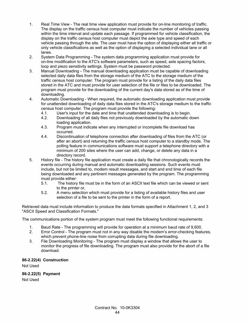
Contract No. 10-0K3304 44
1. Real Time View - The real time view application must provide for on-line monitoring of traffic. The display on the traffic census host computer must indicate the number of vehicles passing within the time interval and update each passage. If programmed for vehicle classification, the display on the traffic census host computer must depict the axle type and speed of each vehicle passing through the site. The user must have the option of displaying either all traffic or only vehicle classifications as well as the option of displaying a selected individual lane or all lanes.
2. System Data Programming - The system data programming application must provide for on-line modification to the ATC's software parameters, such as speed, axle spacing factors, loop and piezo sensitivity settings. System must be password protected.
3. Manual Downloading - The manual downloading application must be capable of downloading selected daily data files from the storage medium of the ATC to the storage medium of the traffic census host computer. The program must provide for a listing of the daily data files stored in the ATC and must provide for user selection of the file or files to be downloaded. The program must provide for the downloading of the current day's data stored as of the time of downloading.
4. Automatic Downloading - When required, the automatic downloading application must provide for unattended downloading of daily data files stored in the ATC's storage medium to the traffic census host computer. The program must provide the following: 4.1. User's input for the date and time that unattended downloading is to begin. 4.2. Downloading of all daily files not previously downloaded by the automatic down
loading application. 4.3. Program must indicate when any interrupted or incomplete file download has
occurred. 4.4. Discontinuation of telephone connection after downloading of files from the ATC (or
after an abort) and returning the traffic census host computer to a standby mode. The polling feature in communications software must support a telephone directory with a minimum of 200 sites where the user can add, change, or delete any data in a directory record.
5. History file - The history file application must create a daily file that chronologically records the events occurring during manual and automatic downloading sessions. Such events must include, but not be limited to, modem result messages, and start and end time of each file being downloaded and any pertinent messages generated by the program. The programming must provide either: 5.1. The history file must be in the form of an ASCII text file which can be viewed or sent
to the printer or, 5.2. A menu selection which must provide for a listing of available history files and user
selection of a file to be sent to the printer in the form of a report.
Retrieved data must include information to produce the data formats specified in Attachment 1, 2, and 3 "ASCII Speed and Classification Formats."
The communications portion of the system program must meet the following functional requirements:
1. Baud Rate - The programming will provide for operation at a minimum baud rate of 9,600. 2. Error Control - The program must not in any way disable the modem’s error-checking features,
which prevent phone-line noise from corrupting data during file downloading. 3. File Downloading Monitoring - The program must display a window that allows the user to
monitor the progress of file downloading. The program must also provide for the abort of a file download.
86-2.22(4) Construction
Not Used
86-2.22(5) Payment
Not Used

Contract No. 10-0K3304 45
ATTACHMENTS
Attachment 1
ASCII SPEED FILE FORMAT Field Length
(characters) Starts in Column
Lane 2 1 Hour 2 4 Count, from 0 to 35 mph 4 7 Count, from 36 to 40 mph 4 12 Count, from 41 to 45 mph 4 17 Count, from 46 to 50 mph 4 22 Count, from 51 to 55 mph 4 27 Count, from 56 to 60 mph 4 32 Count, from 61 to 65 mph 4 37 Count, from 66 to 70 mph 4 42 Count, from 71 to 75 mph 4 47 Count, from 76 to 80 mph 4 52 Count, from 81 to 85 mph 4 57 Count, greater than 86 mph 4 62
ASCII CLASSIFICATION FILE FORMAT Field Length
(characters) Starts in Column
Lane 2 1 Hour 2 4 Count, Class 1 4 7 Count, Class 2 4 12 Count, Class 3 4 17 Count, Class 4 4 22 Count, Class 5 4 27 Count, Class 6 4 32 Count, Class 7 4 37 Count, Class 8 4 42 Count, Class 9 4 47 Count, Class 10 4 52 Count, Class 11 4 57 Count, Class 12 4 62 Count, Class 13 4 67 Count, Class 14 4 72 Count, Class 15 4 77
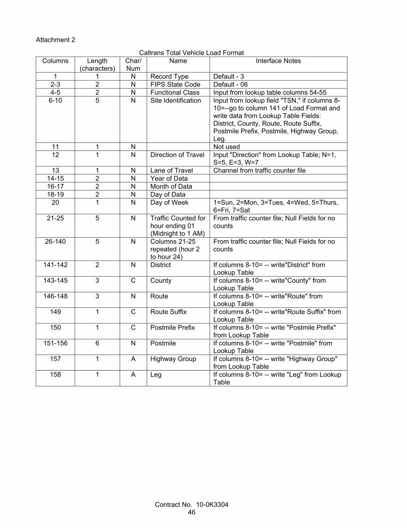
Contract No. 10-0K3304 46
Attachment 2
Caltrans Total Vehicle Load Format Columns Length
(characters) Char/Num
Name Interface Notes
1 1 N Record Type Default - 3 2-3 2 N FIPS State Code Default - 06 4-5 2 N Functional Class Input from lookup table columns 54-55
6-10 5 N Site Identification Input from lookup field "TSN," if columns 8-10=--go to column 141 of Load Format and write data from Lookup Table Fields: District, County, Route, Route Suffix, Postmile Prefix, Postmile, Highway Group, Leg.
11 1 N Not used 12 1 N Direction of Travel Input "Direction" from Lookup Table; N=1,
S=5, E=3, W=7 13 1 N Lane of Travel Channel from traffic counter file
14-15 2 N Year of Data 16-17 2 N Month of Data 18-19 2 N Day of Data
20 1 N Day of Week 1=Sun, 2=Mon, 3=Tues, 4=Wed, 5=Thurs, 6=Fri, 7=Sat
21-25 5 N Traffic Counted for hour ending 01 (Midnight to 1 AM)
From traffic counter file; Null Fields for no counts
26-140 5 N Columns 21-25 repeated (hour 2 to hour 24)
From traffic counter file; Null Fields for no counts
141-142 2 N District If columns 8-10= -- write"District" from Lookup Table
143-145 3 C County If columns 8-10= -- write"County" from Lookup Table
146-148 3 N Route If columns 8-10= -- write"Route" from Lookup Table
149 1 C Route Suffix If columns 8-10= -- write"Route Suffix" from Lookup Table
150 1 C Postmile Prefix If columns 8-10= -- write "Postmile Prefix" from Lookup Table
151-156 6 N Postmile If columns 8-10= -- write "Postmile" from Lookup Table
157 1 A Highway Group If columns 8-10= -- write "Highway Group" from Lookup Table
158 1 A Leg If columns 8-10= -- write "Leg" from Lookup Table
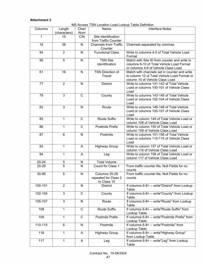
Contract No. 10-0K3304 47
Attachment 3
MS Access TSN Location Load Lookup Table Definition Columns Length
(characters) Char/Num
Name Interface Notes
1 15 C/N Site Identification from Traffic Counter
16 38 N Channels from Traffic Counter
Channels separated by commas
54 2 N Functional Class Write to columns 4-5 of Total Vehicle Load Format
56 5 N TSN Site Identification
Match with Site ID from counter and write to columns 6-10 of Total Vehicle Load Format or columns 4-8 of Vehicle Class Load
61 16 N TSN Direction of Travel
Match with channels set in counter and write to column 12 of Total Vehicle Load Format or column 10 of Vehicle Class Load
77 2 N District Write to columns 141-142 of Total Vehicle Load or columns 100-101 of Vehicle Class Load
79 3 C County Write to columns 143-145 of Total Vehicle Load or columns 102-104 of Vehicle Class Load
82 3 N Route Write to columns 146-148 of Total Vehicle Load or columns 105-107 of Vehicle Class Load
85 1 C Route Suffix Write to column 149 of Total Vehicle Load or column 108 of Vehicle Class Load
86 1 C Postmile Prefix Write to column 150 of Total Vehicle Load or column 109 of Vehicle Class Load
87 6 N Postmile Write to columns 151-156 of Total Vehicle Load or columns 110-115 of Vehicle Class Load
93 1 A Highway Group Write to column 157 of Total Vehicle Load or column 116 of Vehicle Class Load
94 1 A Leg Write to column 158 of Total Vehicle Load or column 117 of Vehicle Class Load
20-24 5 N Total Volume 25-29 5 N Count for Class 1 From traffic counter file; Null Fields for no
counts 30-99 5 N Columns 25-29
repeated for Class 2 to Class 15
From traffic counter file; Null Fields for no counts
100-101 2 N District If columns 6-8= -- write"District" from Lookup Table
102-104 3 C County If columns 6-8= -- write"County" from Lookup Table
105-107 3 N Route If columns 6-8= -- write"Route" from Lookup Table
108 1 C Route Suffix If columns 6-8= -- write"Route Suffix" from Lookup Table
109 1 C Postmile Prefix If columns 6-8= -- write"Postmile Prefix" from Lookup Table
110-115 6 N Postmile If columns 6-8= -- write"Postmile" from Lookup Table
116 1 A Highway Group If columns 6-8= -- write"Highway Group" from Lookup Table
117 1 A Leg If columns 6-8= -- write"Leg" from Lookup Table
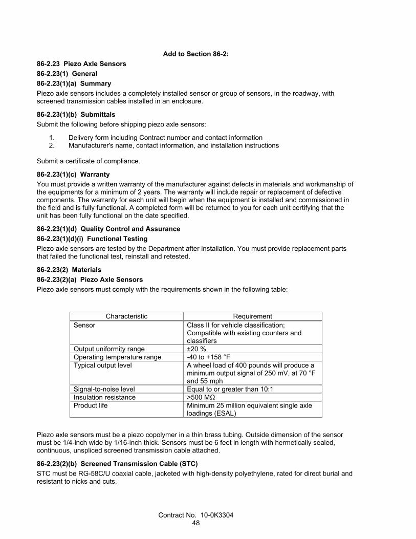
Contract No. 10-0K3304 48
Add to Section 86-2:
86-2.23 Piezo Axle Sensors
86-2.23(1) General
86-2.23(1)(a) Summary
Piezo axle sensors includes a completely installed sensor or group of sensors, in the roadway, with screened transmission cables installed in an enclosure.
86-2.23(1)(b) Submittals
Submit the following before shipping piezo axle sensors:
1. Delivery form including Contract number and contact information 2. Manufacturer's name, contact information, and installation instructions
Submit a certificate of compliance.
86-2.23(1)(c) Warranty
You must provide a written warranty of the manufacturer against defects in materials and workmanship of the equipments for a minimum of 2 years. The warranty will include repair or replacement of defective components. The warranty for each unit will begin when the equipment is installed and commissioned in the field and is fully functional. A completed form will be returned to you for each unit certifying that the unit has been fully functional on the date specified.
86-2.23(1)(d) Quality Control and Assurance
86-2.23(1)(d)(i) Functional Testing
Piezo axle sensors are tested by the Department after installation. You must provide replacement parts that failed the functional test, reinstall and retested.
86-2.23(2) Materials
86-2.23(2)(a) Piezo Axle Sensors
Piezo axle sensors must comply with the requirements shown in the following table:
Characteristic Requirement Sensor Class II for vehicle classification;
Compatible with existing counters and classifiers
Output uniformity range ±20 % Operating temperature range -40 to +158 °F Typical output level
A wheel load of 400 pounds will produce a minimum output signal of 250 mV, at 70 °F and 55 mph
Signal-to-noise level Equal to or greater than 10:1 Insulation resistance >500 MΩ Product life Minimum 25 million equivalent single axle
loadings (ESAL)
Piezo axle sensors must be a piezo copolymer in a thin brass tubing. Outside dimension of the sensor must be 1/4-inch wide by 1/16-inch thick. Sensors must be 6 feet in length with hermetically sealed, continuous, unspliced screened transmission cable attached.
86-2.23(2)(b) Screened Transmission Cable (STC)
STC must be RG-58C/U coaxial cable, jacketed with high-density polyethylene, rated for direct burial and resistant to nicks and cuts.

Contract No. 10-0K3304 49
STC length must reach the TMS enclosure without any splices and have ten feet of slack. Coil the excess STC in the TMS enclosure. STC terminations are made by the Department.
86-2.23(3) Construction
Install piezo axle sensors in an array of 2 inductive loop detector and 1 piezo axle sensors per lane.
Install piezo axle sensors and STC in conformance with the manufacturer's recommendations. Saw cuts in the pavement for axle sensors and STC must conform to the following:
1. Saw cuts must be cleaned with compressed air to remove all excess moisture and debris. For
repairing damaged saw cuts, all loose spalled material must be cleaned away from the saw cut, chipping back to sound asphalt concrete or concrete pavement, and cleaned away.
2. Residue from slot cutting activities must not be allowed to flow across shoulders or lanes occupied by traffic and must be removed from the pavement surface before residue flows off. Dispose of residue from slot cutting activities.
3. Before setting, surplus sealant must be removed from the adjacent road surface without using solvents.
Fill piezo axle sensor slots with epoxy grout sealant. The sealant temperature must not exceed 169 degrees F while curing and must be adequately set before reopening the lane to public traffic.
Fill STC slots with elastomeric sealant. Elastomeric sealant must conform to section 86-5.01A(3)(a).
86-2.23(3)(a) Epoxy Grout Sealant
Epoxy grout sealant must be Global Resins PU200, International Road Dynamics AS 475, or equivalent.
86-2.23(4) Payment
Not Used
Add to section 86-3.04:
Cabinet must be Model 334L and consist of a housing (B), a mounting cage 1, and the following listed equipment. The equipment must comply with chapter 6 of TEES.
1. Service panel no. 1 2. Power distribution assembly no. 3 3. Input file (I file) 4. C1 harness 5. Controller and equipment shelves 6. Dual fan assembly with thermostatic control 7. Mechanical armature-type relays 8. Input panel
Before shipping to the job site, submit each 334L cabinet to METS for acceptance testing.
Notify the Engineer when each 334L cabinet is ready for functional testing. Functional testing will be conducted by the Department.
Each power distribution assembly must include the following equipment:
1. Two duplex NEMA 5-15R controller receptacle (rear mount) 2. One 30 A, 1-pole, 120 V(ac) main circuit breaker 3. Three 15 A, 1-pole, 120 V(ac) circuit breaker 4. One duplex GFCI NEMA 15 A, receptacle (front mount)
Furnish 3 shelves as shown. Each shelf must be attached to the tops of 2 supporting angles with 4 screws. Supporting angles must extend from the front to the back rails. The front of the shelf must abut the front member of the mounting cage. Arrange shelves as shown. The angles must be designed to support a minimum of 50 pounds each. The horizontal side of each angle must be a minimum of 3 inches. The angles must be vertically adjustable.
Contract No. 10-0K3304 50
Furnish 3 terminal blocks as shown. Terminal blocks must comply with Chapter 6 of TEES, except the screw size must be 8-32.
Furnish a maintenance manual or a combined maintenance and operation manual for all controller units, auxiliary equipment, vehicle detector sensor units, control units, and amplifiers. Submit manual when the controllers are delivered for testing or, if ordered by the Engineer, before purchasing. The manual must include the following:
1. Specifications 2. Design characteristics 3. General operation theory 4. Function of all controls 5. Troubleshooting procedure (diagnostic routine) 6. Block circuit diagram 7. Geographical layout of components 8. Schematic diagrams 9. List of replaceable component parts with stock numbers
Add to section 86-5.01A(1):
Loop wire must be Type 2.
Loop detector lead-in cable must be Type B.
Slots must be filled with hot-melt rubberized asphalt sealant.
The depth of the loop sealant above the top of the uppermost loop wire in the sawed slots must be 2 inches, minimum.

Contract No. 10-0K3304 51
REVISED STANDARD SPECIFICATIONS APPLICABLE TO THE 2010 EDITION
OF THE STANDARD SPECIFICATIONS


Contract No. 10-0K3304 1 of 82
REVISED STANDARD SPECIFICATIONS DATED 10-19-12
Revised standard specifications are under headings that correspond with the main-section headings of the Standard Specifications. A main-section heading is a heading shown in the table of contents of the Standard Specifications. A date under a main-section heading is the date of the latest revision to the section.
Each revision to the Standard Specifications begins with a revision clause that describes a revision to the Standard Specifications or introduces a revision to the Standard Specifications. For a revision clause that describes a revision, the date on the right above the clause is the publication date of the revision. For a revision clause that introduces a revision, the date on the right above a revised term, phrase, clause, paragraph, or section is the publication date of the revised term, phrase, clause, paragraph, or section. For a multiple-paragraph or multiple-section revision, the date on the right above a paragraph or section is the publication date of the paragraphs or sections that follow.
Any paragraph added or deleted by a revision clause does not change the paragraph numbering of the Standard Specifications for any other reference to a paragraph of the Standard Specifications.
DIVISION I GENERAL PROVISIONS
1 GENERAL 10-19-12
Replace "current" in the 2nd paragraph of section 1-1.05 with:
04-20-12
most recent
Add to the 4th paragraph of section 1-1.05:
04-20-12
Any reference directly to a revised standard specification section is for convenience only. Lack of a direct reference to a revised standard specification section does not indicate a revised standard specification for the section does not exist.
Add to the 1st table in section 1-1.06:
10-19-12
TRO time-related overhead
06-20-12
Delete the abbreviation and its meaning for UDBE in the 1st table of section 1-1.06.
10-19-12
Delete "Contract completion date" and its definition in section 1-1.07B.
10-19-12
Delete "critical delay" and its definition in section 1-1.07B.

Contract No. 10-0K3304 2 of 82
Replace "day" and its definition in section 1-1.07B with:
10-19-12
day: 24 consecutive hours running from midnight to midnight; calendar day.
1. business day: Day on the calendar except a Saturday and a holiday. 2. working day: Time measure unit for work progress. A working day is any 24-consecutive-hour period
except: 2.1. Saturday and holiday. 2.2. Day during which you cannot perform work on the controlling activity for at least 50 percent of
the scheduled work shift with at least 50 percent of the scheduled labor and equipment due to any of the following: 2.2.1. Adverse weather-related conditions. 2.2.2. Maintaining traffic under the Contract. 2.2.3. Suspension of a controlling activity that you and the Engineer agree benefits both
parties. 2.2.4. Unanticipated event not caused by either party such as:
2.2.4.1. Act of God. 2.2.4.2. Act of a public enemy. 2.2.4.3. Epidemic. 2.2.4.4. Fire. 2.2.4.5. Flood. 2.2.4.6. Governor-declared state of emergency. 2.2.4.7. Landslide. 2.2.4.8. Quarantine restriction.
2.2.5. Issue involving a third party, including: 2.2.5.1. Industry or area-wide labor strike. 2.2.5.2. Material shortage. 2.2.5.3. Freight embargo. 2.2.5.4. Jurisdictional requirement of a law enforcement agency. 2.2.5.5. Workforce labor dispute of a utility or nonhighway facility owner resulting in
a nonhighway facility rearrangement not described and not solely for the Contractor's convenience. Rearrangement of a nonhighway facility includes installation, relocation, alteration, or removal of the facility.
2.3. Day during a concurrent delay. 3. original working days:
3.1. Working days to complete the work shown on the Notice to Bidders for a non–cost plus time based bid.
3.2. Working days bid to complete the work for a cost plus time based bid.
Where working days is specified without the modifier "original" in the context of the number of working days to complete the work, interpret the number as the number of original working days as adjusted by any time adjustment.
Replace "Contract" in the definition of "early completion time" in section 1-1.07B with:
10-19-12
work
Replace "excusable delay" and its definition in section 1-1.07B with:
10-19-12
delay: Event that extends the completion of an activity.
1. excusable delay: Delay caused by the Department and not reasonably foreseeable when the work began such as: 1.1. Change in the work 1.2. Department action that is not part of the Contract

Contract No. 10-0K3304 3 of 82
1.3. Presence of an underground utility main not described in the Contract or in a location substantially different from that specified
1.4. Described facility rearrangement not rearranged as described, by the utility owner by the date specified, unless the rearrangement is solely for the Contractor's convenience
1.5. Department's failure to obtain timely access to the right-of-way 1.6. Department's failure to review a submittal or provide notification in the time specified
2. critical delay: Excusable delay that extends the scheduled completion date 3. concurrent delay: Occurrence of at least 2 of the following events in the same period of time, either
partially or entirely: 3.1. Critical delay 3.2. Delay to a controlling activity caused by you 3.3. Non–working day
Replace "project" in the definition of "scheduled completion date" in section 1-1.07B with:
10-19-12
work
Add to section 1-1.07B:
10-19-12
Contract time: Number of original working days as adjusted by any time adjustment.
Add to section 1-1.07B:
06-20-12
Disadvantaged Business Enterprise: Disadvantaged Business Enterprise as defined in 49 CFR 26.5.
Replace "PO BOX 911" in the District 3 mailing address in the table in section 1-1.08 with:
04-20-12
703 B ST
Add to the table in section 1-1.11:
01-20-12
Office Engineer–All Projects Currently Advertised
http://www.dot.ca.gov/hq/esc/oe/weekly_ads/all_advertised.php
-- --
^^^^^^^^^^^^^^^^^^^^^^^^^^^^^^^^^^^^^^^^
2 BIDDING 10-19-12
Replace the 3rd paragraph of section 2-1.06B with:
01-20-12
If an Information Handout or cross sections are available:
1. You may view them at the Contract Plans and Special Provisions link at the Office Engineer–All Projects Currently Advertised Web site
2. For an informal-bid contract, you may obtain them at the Bidders' Exchange street address

Contract No. 10-0K3304 4 of 82
01-20-12
Add a paragraph break between the 1st and 2nd sentences of the 5th paragraph of section 2-1.06B.
Add between "and" and "are" in item 2 in the list in the 7th paragraph of section 2-1.06B:
04-20-12
they
06-20-12
Delete "Underutilized" in "Underutilized Disadvantabed Business Enterprises" in the heading of section 2-1.12B.
06-20-12
Delete U in UDBE at each occurrence in section 2-1.12B.
Replace the 2nd paragraph of section 2-1.12B(1) with:
06-20-12
To ensure equal participation of DBEs provided in 49 CFR 26.5, the Department shows a goal for DBEs.
06-20-12
Delete the 3rd paragraph of section 2-1.12B(1):
Replace the 7th paragraph of section 2-1.12B(1) with:
06-20-12
All DBE participation will count toward the Department's federally-mandated statewide overall DBE goal.
Replace "offered" at the end of the 2nd sentence of item 7 in the list of 2nd paragraph of section 2-1.12B(3) with:
06-20-12
provided
01-20-12
Delete the 2nd paragraph of section 2-1.33A.
Replace the 3rd paragraph of section 2-1.33A with:
01-20-12
Except for each subcontracted bid item number and corresponding percentage and proof of each required SSPC QP certification, do not fax submittals.
Add to section 2-1.33C:
10-19-12
On the Subcontractor List, you must either submit each subcontracted bid item number and corresponding percentage with your bid or fax these numbers and percentages to (916) 227-6282 within 24 hours after bid opening. Failure to do so results in a nonresponsive bid.
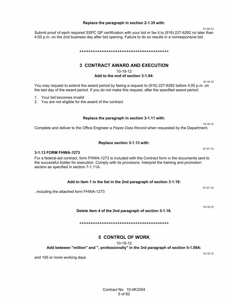
Contract No. 10-0K3304 5 of 82
Replace the paragraph in section 2-1.35 with:
01-20-12
Submit proof of each required SSPC QP certification with your bid or fax it to (916) 227-6282 no later than 4:00 p.m. on the 2nd business day after bid opening. Failure to do so results in a nonresponsive bid.
^^^^^^^^^^^^^^^^^^^^^^^^^^^^^^^^^^^^^^^^
3 CONTRACT AWARD AND EXECUTION 10-19-12
Add to the end of section 3-1.04:
10-19-12
You may request to extend the award period by faxing a request to (916) 227-6282 before 4:00 p.m. on the last day of the award period. If you do not make this request, after the specified award period:
1. Your bid becomes invalid 2. You are not eligible for the award of the contract
Replace the paragraph in section 3-1.11 with:
10-19-12
Complete and deliver to the Office Engineer a Payee Data Record when requested by the Department.
Replace section 3-1.13 with:
07-27-12
3-1.13 FORM FHWA-1273
For a federal-aid contract, form FHWA-1273 is included with the Contract form in the documents sent to the successful bidder for execution. Comply with its provisions. Interpret the training and promotion section as specified in section 7-1.11A.
Add to item 1 in the list in the 2nd paragraph of section 3-1.18:
07-27-12
, including the attached form FHWA-1273
10-19-12
Delete item 4 of the 2nd paragraph of section 3-1.18.
^^^^^^^^^^^^^^^^^^^^^^^^^^^^^^^^^^^^^^^^
5 CONTROL OF WORK 10-19-12
Add between "million" and ", professionally" in the 3rd paragraph of section 5-1.09A:
10-19-12
and 100 or more working days

Contract No. 10-0K3304 6 of 82
Add to the list in the 4th paragraph of section 5-1.09A:
10-19-12
9. Considering discussing with and involving all stakeholders in evaluating potential VECPs
Add to the end of item 1.1 in the list in the 7th paragraph of section 5-1.09A:
10-19-12
, including VECPs
Replace the 1st paragraph of section 5-1.09C with:
10-19-12
For a contract with a total bid over $10 million and 100 or more working days, training in partnering skills development is required.
10-19-12
Delete the 2nd paragraph of section 5-1.09C.
Replace "at least 2 representatives" in the 5th paragraph of section 5-1.09C with:
10-19-12
field supervisory personnel
Replace the 1st and 2nd sentences in the 7th paragraph of section 5-1.13B(1) with:
06-20-12
If a DBE is decertified before completing its work, the DBE must notify you in writing of the decertification date. If a business becomes a certified DBE before completing its work, the business must notify you in writing of the certification date.
Replace "90" in the last sentence of the 7th paragraph of section 5-1.13B(1) with:
06-20-12
30
Replace "Underutilized" in "Underutilized Disadvantabed Business Enterprises" in the heading of section 5-1.13B(2) with:
06-20-12
Performance of
06-20-12
Delete U in UDBE at each occurrence in section 5-1.13B(2).
Replace the 3rd paragraph of section 5-1.13B(2) with:
06-20-12
Do not terminate or substitute a listed DBE for convenience and perform the work with your own forces or obtain materials from other sources without authorization from the Department.

Contract No. 10-0K3304 7 of 82
Replace item 6 in the list in the 4th paragraph of section 5-1.13B(2) with:
06-20-12
6. Listed DBE is ineligible to work on the project because of suspension or debarment.
Add to the list in the 4th paragraph of section 5-1.13B(2):
06-20-12
8. Listed DBE voluntarily withdraws with written notice from the Contract. 9. Listed DBE is ineligible to receive credit for the type of work required. 10. Listed DBE owner dies or becomes disabled resulting in the inability to perform the work on the
Contract. 11. Department determines other documented good cause.
Add between the 4th and 5th paragraphs of section 5-1.13B(2):
07-20-12
Notify the original DBE of your intent to use other forces or material sources and provide the reasons. Provide the DBE with 5 days to respond to your notice and advise you and the Department of the reasons why the use of other forces or sources of materials should not occur. Your request to use other forces or material sources must include:
1. 1 or more of the reasons listed in the preceding paragraph 2. Notices from you to the DBE regarding the request 3. Notices from the DBE to you regarding the request
Add between "terminated" and ", you" in the 5th paragraph of section 5-1.13B(2):
07-20-12
or substituted
Replace "Contract" in item 1 in the list in the 5th paragraph of section 5-1.13C with:
10-19-12
work
Replace "Reserved" in section 5-1.20C with:
10-19-12
If the Contract includes an agreement with a railroad company, the Department makes the provisions of the agreement available in the Information Handout in the document titled "Railroad Relations and Insurance Requirements." Comply with the requirements in the document.
Add between the 2nd and 3rd paragraphs of section 5-1.23A:
10-19-12
Submit action and informational submittals to the Engineer.
Add to section 5-1.36C:
07-20-12
If the Contract does not include an agreement with a railroad company, do not allow personnel or equipment on railroad property.
Prevent material, equipment, and debris from falling onto railroad property.
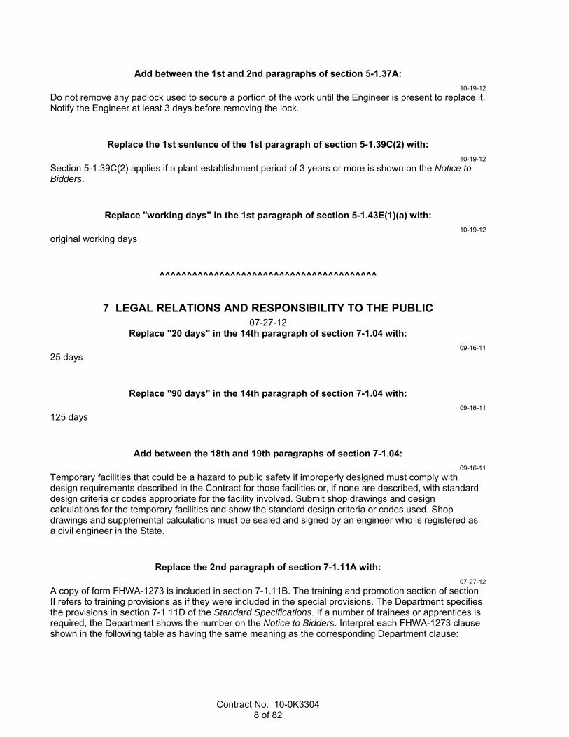
Contract No. 10-0K3304 8 of 82
Add between the 1st and 2nd paragraphs of section 5-1.37A:
10-19-12
Do not remove any padlock used to secure a portion of the work until the Engineer is present to replace it. Notify the Engineer at least 3 days before removing the lock.
Replace the 1st sentence of the 1st paragraph of section 5-1.39C(2) with:
10-19-12
Section 5-1.39C(2) applies if a plant establishment period of 3 years or more is shown on the Notice to Bidders.
Replace "working days" in the 1st paragraph of section 5-1.43E(1)(a) with:
10-19-12
original working days
^^^^^^^^^^^^^^^^^^^^^^^^^^^^^^^^^^^^^^^^
7 LEGAL RELATIONS AND RESPONSIBILITY TO THE PUBLIC 07-27-12
Replace "20 days" in the 14th paragraph of section 7-1.04 with:
09-16-11
25 days
Replace "90 days" in the 14th paragraph of section 7-1.04 with:
09-16-11
125 days
Add between the 18th and 19th paragraphs of section 7-1.04:
09-16-11
Temporary facilities that could be a hazard to public safety if improperly designed must comply with design requirements described in the Contract for those facilities or, if none are described, with standard design criteria or codes appropriate for the facility involved. Submit shop drawings and design calculations for the temporary facilities and show the standard design criteria or codes used. Shop drawings and supplemental calculations must be sealed and signed by an engineer who is registered as a civil engineer in the State.
Replace the 2nd paragraph of section 7-1.11A with:
07-27-12
A copy of form FHWA-1273 is included in section 7-1.11B. The training and promotion section of section II refers to training provisions as if they were included in the special provisions. The Department specifies the provisions in section 7-1.11D of the Standard Specifications. If a number of trainees or apprentices is required, the Department shows the number on the Notice to Bidders. Interpret each FHWA-1273 clause shown in the following table as having the same meaning as the corresponding Department clause:

Contract No. 10-0K3304 9 of 82
FHWA-1273 Nondiscrimination Clauses FHWA-1273
section FHWA-1273 clause Department clause
Training and Promotion
In the event a special provision for training is provided under this contract, this subparagraph will be superseded as indicated in the special provision.
If section 7-1.11D applies, section 7-1.11D supersedes this subparagraph.
Records and Reports
If on-the-job training is being required by special provision, the contractor will be required to collect and report training data.
If the Contract requires on-the-job training, collect and report training data.
Replace the form in section 7-1.11B with:
07-20-12

Contract No. 10-0K3304 10 of 82

Contract No. 10-0K3304 11 of 82

Contract No. 10-0K3304 12 of 82

Contract No. 10-0K3304 13 of 82

Contract No. 10-0K3304 14 of 82

Contract No. 10-0K3304 15 of 82
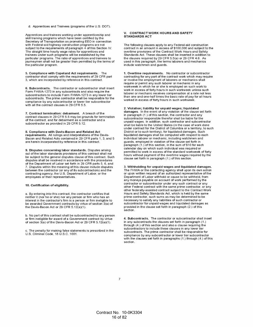
Contract No. 10-0K3304 16 of 82
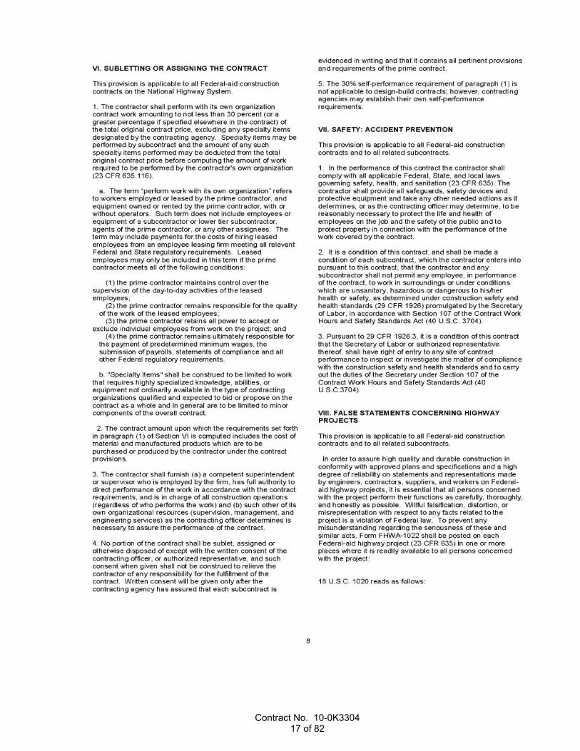
Contract No. 10-0K3304 17 of 82

Contract No. 10-0K3304 18 of 82

Contract No. 10-0K3304 19 of 82

Contract No. 10-0K3304 20 of 82

Contract No. 10-0K3304 21 of 82
^^^^^^^^^^^^^^^^^^^^^^^^^^^^^^^^^^^^^^^^
8 PROSECUTION AND PROGRESS 10-19-12
Replace "working days" in the 1st paragraph of section 8-1.02B(1) with:
10-19-12
original working days
Replace "working days" at each occurrence in the 1st paragraph of section 8-1.02C(1) with:
10-19-12
original working days
04-20-12
Delete the 4th paragraph of section 8-1.02C(1).
Replace "Contract" in the 9th paragraph of section 8-1.02C(1) with:
10-19-12
work
Replace the 1st paragraph of section 8-1.02C(3)(a) with:
04-20-12
Submit a description of your proposed schedule software for authorization.
04-20-12
Delete the last paragraph of section 8-1.02C(3)(a).
Replace section 8-1.02C(3)(b) with:
10-19-12
8-1.02C(3)(b) Reserved
04-20-12
Delete the 3rd paragraph of section 8-1.02C(5).
Replace "Contract" in the last paragraph of section 8-1.02C(5) with:
10-19-12
original
Replace "working days" in the 1st paragraph of section 8-1.02D(1) with:
10-19-12
original working days
Replace "8-1.02D(1)" in the 2nd paragraph of section 8-1.02D(1) with:
01-20-12
8-1.02C(1)

Contract No. 10-0K3304 22 of 82
Replace "Contract" in the 3rd paragraph of section 8-1.02D(2) with:
10-19-12
work
Replace "Contract" in item 9 in the list in the 4th paragraph of section 8-1.02D(4) with:
10-19-12
work
Replace "Contract completion" in the 4th paragraph of section 8-1.02D(6) with:
10-19-12
work completion
Replace "Contract working days" in the 4th paragraph of section 8-1.02D(6) with:
10-19-12
original working days
04-20-12
Delete items 1.3 and 1.4 in the list in the 1st paragraph of section 8-1.02D(10).
Replace the last paragraph of section 8-1.04B with:
10-19-12
The Department does not adjust time for starting before receiving notice of Contract approval.
Replace the 1st paragraph of section 8-1.05 with:
10-19-12
Contract time starts on the last day specified to start job site activities in section 8-1.04 or on the day you start job site activities, whichever occurs first.
Replace the 2nd paragraph of section 8-1.05 with:
10-19-12
Complete the work within the Contract time.
10-19-12
Delete "unless the Contract is suspended for reasons unrelated to your performance" in the 4th paragraph of section 8-1.05.
Replace the headings and paragraphs in section 8-1.06 with:
10-19-12
The Engineer may suspend work wholly or in part due to conditions unsuitable for work progress. Provide for public safety and a smooth and unobstructed passageway through the work zone during the suspension as specified under sections 7-1.03 and 7-1.04. Providing the passageway is force account work. The Department makes a time adjustment for the suspension due to a critical delay.
The Engineer may suspend work wholly or in part due to your failure to (1) fulfill the Engineer's orders, (2) fulfill a Contract part, or (3) perform weather-dependent work when conditions are favorable so that weather-related unsuitable conditions are avoided or do not occur. The Department may provide for a

Contract No. 10-0K3304 23 of 82
smooth and unobstructed passageway through the work during the suspension and deduct the cost from payments. The Department does not make a time adjustment for the suspension.
Upon the Engineer's order of suspension, suspend work immediately. Resume work when ordered.
Replace the 1st sentence in the 1st paragraph of section 8-1.07B with:
10-19-12
For a critical delay, the Department may make a time adjustment.
Add to the end of section 8-1.07C:
10-19-12
The Department does not make a payment adjustment for overhead incurred during non–working days that extend the Contract into an additional construction season.
Replace the 1st paragraph of section 8-1.07C with:
10-19-12
For an excusable delay that affects your costs, the Department may make a payment adjustment.
Replace "8-1.08B and 8-1.08C" in the 1st paragraph of section 8-1.10A with:
08-05-11
8-1.10B and 8-1.10C
Replace section 8-1.10D with:
10-19-12
8-1.10D Reserved
^^^^^^^^^^^^^^^^^^^^^^^^^^^^^^^^^^^^^^^^
9 PAYMENT 10-19-12
Replace "in" in the 3rd paragraph of section 9-1.04A with:
10-19-12
for
Add to the end of section 9-1.04A:
10-19-12
For nonsubcontracted work paid by force account for a contract with a TRO bid item, the markups are those shown in the following table instead of those specified in sections 9-1.04B–D:
Cost Percent markupLabor 30 Materials 10 Equipment rental 10

Contract No. 10-0K3304 24 of 82
04-20-12
Delete ", Huntington Beach," in the 3rd paragraph of section 9-1.07A.
Replace the formula in section 9-1.07B(2) with:
04-20-12
Qh = HMATT x Xa
Replace "weight of dry aggregate" in the definition of the variable Xa in section 9-1.07B(2) with:
04-20-12
total weight of HMA
Replace the formula in section 9-1.07B(3) with:
04-20-12
Qrh = RHMATT x 0.80 x Xarb
Replace "weight of dry aggregate" in the definition of the variable Xarb in section 9-1.07B(3) with:
04-20-12
total weight of rubberized HMA
Replace the heading of section 9-1.07B(4) with:
04-20-12
Hot Mix Asphalt with Modified Asphalt Binder
Add between "in" and "modified" in the introductory clause of section 9-1.07B(4):
04-20-12
HMA with
Replace the formula in section 9-1.07B(4) with:
04-20-12
Qmh = MHMATT x [(100 - Xam) / 100] x Xmab
Replace "weight of dry aggregate" in the definition of the variable Xmab in section 9-1.07B(4) with:
04-20-12
total weight of HMA
Replace the formula in section 9-1.07B(5) with:
04-20-12
Qrap = HMATT x Xaa
Replace "weight of dry aggregate" in the definitions of the variables Xaa and Xta in section 9-1.07B(5) with:
04-20-12
total weight of HMA

Contract No. 10-0K3304 25 of 82
Add after the variable definitions in section 9-1.07B(9):
04-20-12
The quantity of extender oil is included in the quantity of asphalt.
Replace the headings and paragraphs in section 9-1.11 with:
10-19-12
9-1.11A General
Section 9-1.11 applies if a bid item for time-related overhead is included in the Contract. If a bid item for time-related overhead is included, you must exclude the time-related overhead from every other bid item price.
9-1.11B Payment Quantity
The TRO quantity does not include the number of working days to complete plant establishment work.
For a contract with a TRO lump sum quantity on the Bid Item List, the Department pays you based on the following conversions:
1. LS unit of measure is replaced with WDAY 2. Lump sum quantity is replaced with the number of working days bid 3. Lump sum unit price is replaced with the item total divided by the number of working days bid 9-1.11C Payment Inclusions
Payment for the TRO bid item includes payment for time-related field- and home-office overhead for the time required to complete the work.
The field office overhead includes time-related expenses associated with the normal and recurring construction activities not directly attributed to the work, including:
1. Salaries, benefits, and equipment costs of: 1.1. Project managers 1.2. General superintendents 1.3. Field office managers 1.4. Field office staff assigned to the project
2. Rent 3. Utilities 4. Maintenance 5. Security 6. Supplies 7. Office equipment costs for the project's field office The home-office overhead includes the fixed general and administrative expenses for operating your business, including:
1. General administration 2. Insurance 3. Personnel and subcontract administration 4. Purchasing 5. Accounting 6. Project engineering and estimating Payment for the TRO bid item does not include payment for:
1. The home-office overhead expenses specifically related to: 1.1. Your other contracts or other businesses 1.2. Equipment coordination 1.3. Material deliveries 1.4. Consultant and legal fees

Contract No. 10-0K3304 26 of 82
2. Non-time-related costs and expenses such as mobilization, licenses, permits, and other charges incurred once during the Contract
3. Additional overhead involved in incentive/disincentive provisions to satisfy an internal milestone or multiple calendar requirements
4. Additional overhead involved in performing additional work that is not a controlling activity 5. Overhead costs incurred by your subcontractors of any tier or suppliers 9-1.11D Payment Schedule
For progress payments, the total work completed for the TRO bid item is the number of working days shown for the pay period on the Weekly Statement of Working Days.
For progress payments, the Department pays a unit price equal to the lesser of the following amounts:
1. Price per working day as bid or as converted under section 9-1.11B. 2. 20 percent of the total bid divided by the number of original working days For a contract without plant establishment work, the Department pays you the balance due of the TRO item total as specified in section 9-1.17B.
For a contract with plant establishment work, the Department pays you the balance due of the TRO item total in the 1st progress payment after all non–plant establishment work is completed.
9-1.11E Payment Adjustments
The 3rd paragraph of section 9-1.17C does not apply.
The Department does not adjust the unit price for an increase or decrease in the TRO quantity except as specified in section 9-1.11E.
Section 9-1.17D(2)(b) does not apply except as specified for the audit report below.
If the TRO bid item quantity exceeds 149 percent of the quantity shown on the Bid Item List or as converted under section 9-1.11B, the Engineer may adjust or you may request an adjustment of the unit price for the excess quantity. For the adjustment, submit an audit report within 60 days of the Engineer's request. The report must be prepared as specified for an audit report for an overhead claim in section 9-1.17D(2)(b).
Within 20 days of the Engineer's request, make your financial records available for an audit by the State for the purpose of verifying the actual rate of TRO described in your audit. The actual rate of TRO described is subject to the Engineer's authorization.
The Department pays the authorized actual rate for TRO in excess of 149 percent of the quantity shown on the Bid Item List or as converted under section 9-1.11B.
The Department pays for 1/2 the cost of the report; the Contractor pays for the other 1/2. The cost is determined under section 9-1.05.
10-19-12
Delete "revised Contract" in item 1 of the 1st paragraph of section 9-1.16E(2).
Replace "2014" in the 1st paragraph of section 9-1.16F with:
10-19-12
2020
Replace the 2nd paragraph of section 9-1.17C with:
10-19-12
Submit either a written acceptance of the proposed final estimate or a claim statement postmarked or hand delivered before the 31st day after receiving the proposed final estimate.

Contract No. 10-0K3304 27 of 82
Add between "the" and "final estimate" in the 1st sentence in the 3rd paragraph of section 9-1.17C:
10-19-12
proposed
^^^^^^^^^^^^^^^^^^^^^^^^^^^^^^^^^^^^^^^^^^^^^^^^^^^^^^^^^^^^
DIVISION II GENERAL CONSTRUCTION 10 GENERAL
07-20-12 Replace "Reserved" in section 10-1 with:
01-20-12
10-1.01 GENERAL
Reserved
10-1.02 WORK SEQUENCING
Before obliterating any traffic stripes, pavement markings, and pavement markers to be replaced at the same location, reference the stripes, markings, and markers. Include limits and transitions with control points to reestablish the new stripes, markings, and markers.
10-1.03 TIME CONSTRAINTS
Reserved
10-1.04–10-1.10 RESERVED
Replace "Reserved" in section 10-2.01 with:
07-20-12
10-2.01A General
Reserved
10-2.01B–10-2.01H Reserved
Replace the heading of section 10-2.02 with:
07-20-12
CALGREEN TIER 1
Replace section 10-2.03 with:
07-20-12
10-2.03 LEED
10-2.03A–10-2.03H Reserved
^^^^^^^^^^^^^^^^^^^^^^^^^^^^^^^^^^^^^^^^

Contract No. 10-0K3304 28 of 82
12 TEMPORARY TRAFFIC CONTROL 10-19-12
Replace the 1st paragraph of section 12-3.01A(4) with:
10-19-12
Category 2 temporary traffic control devices must be on FHWA's list of acceptable, crashworthy Category 2 hardware for work zones. This list is available on FHWA's Safety Program Web site.
Replace "project" in the 4th paragraph of section 12-3.02C with:
10-19-12
work
Replace "project" in the 3rd paragraph of section 12-3.07C with:
10-19-12
work
Add between the 7th and 8th paragraphs of section 12-4.03:
10-19-12
The contingency plan must identify the operations, equipment, processes, and materials that may fail and delay a reopening of a closure to traffic. List the additional or alternate equipment, materials, or workers necessary to ensure continuing operations and on-time opening of closures whenever a problem occurs. If the additional or alternate equipment, materials, or workers are not on site, specify their location, the method for mobilizing these items, and the required time to complete mobilization.
Based on the Engineer's review, additional materials, equipment, workers, or time to complete operations from that specified in the contingency plan may be required.
Provide a general time-scaled logic diagram displaying the major activities and sequence of planned operations that comply with the requirements of section 12-4.03. For each operation, identify the critical event when the contingency plan will be activated.
Submit any revisions to the contingency plan for an operation at least 3 business days before starting that operation. Do not close any lanes until the contingency plan has been authorized.
The 5th paragraph of section 5-1.23B(1) does not apply to reviewing contingency plans.
Replace section 12-7 with:
09-16-11
12-7 RESERVED
^^^^^^^^^^^^^^^^^^^^^^^^^^^^^^^^^^^^^^^^
13 WATER POLLUTION CONTROL 10-19-12
Add to section 13-1.01A:
01-20-12
Comply with the Department's general permit issued by the State Water Resources Control Board for Order No. 99-06-DWQ, NPDES No. CAS000003, National Pollutant Discharge Elimination System (NPDES) Permit, Statewide Storm Water Permit and Waste Discharge Requirements (WDRs) for the State of California, Department of Transportation (Caltrans). The Department's general permit governs stormwater and nonstormwater discharges from the Department's properties, facilities, and activities. The

Contract No. 10-0K3304 29 of 82
Department's general permit may be viewed at the Web site for the State Water Resources Control Board, Storm Water Program, Caltrans General Permit.
Add to the list in the 1st paragraph of section 13-1.01D(3)(b):
10-21-11
3. Have completed SWRCB approved QSD training and passed the QSD exam
Add to the list in the 2nd paragraph of section 13-1.01D(3)(b):
10-21-11
3. Have completed SWRCB approved QSP training and passed the QSP exam
Replace "working days" at each occurrence in section 13-3.04 with.
10-19-12
original working days
Replace the paragraph in section 13-4.04 with:
04-20-12
Not Used
10-19-12
Delete "or stockpile" in the 3rd paragraph of section 13-5.02F.
Replace section 13-5.03F with:
04-20-12
13-5.03F Reserved
10-19-12
Delete "or stockpile" in item 1 in the list in the 1st paragraph of section 13-5.03K.
10-19-12
Delete the 3rd paragraph of section 13-5.03K.
Replace the 2nd sentence in the 1st paragraph of section 13-9.01A with:
10-19-12
You may use any of the following systems for temporary concrete washout:
1. Temporary concrete washout facility 2. Portable temporary concrete washout 3. Temporary concrete washout bin
Replace the 2nd paragraph of section 13-9.01B with:
10-19-12
Retain and submit an informational submittal for records of disposed concrete waste.

Contract No. 10-0K3304 30 of 82
10-19-12
Delete the 4th paragraph of section 13-9.01B.
10-19-12
Delete "if authorized" in the 1st sentence in the 1st paragraph of section 13-9.02A.
Replace "at least 3-inch" in the 3rd sentence in the 1st paragraph of section 13-9.02A with:
10-19-12
6-inch
^^^^^^^^^^^^^^^^^^^^^^^^^^^^^^^^^^^^^^^^
15 EXISTING FACILITIES 10-19-12
Replace the 1st paragraph of section 15-5.01C(1) with:
10-19-12
Before starting deck rehabilitation activities, complete the removal of any traffic stripes, pavement markings, and pavement markers.
Replace the 2nd and 3rd paragraphs of section 15-5.01C(2) with:
10-19-12
Perform the following activities in the order listed:
1. Abrasive blast the deck surface with steel shot. Perform abrasive blasting after the removal of any unsound concrete and placement of any rapid setting concrete patches.
2. Sweep the deck surface. 3. Blow the deck surface clean using high-pressure air.
Replace the 2nd paragraph of section 15-5.01C(4) with:
10-19-12
Before removing asphalt concrete surfacing, verify the depth of the surfacing at the supports and midspans of each structure (1) in each shoulder, (2) in the traveled way, and (3) at the roadway crown, if a crown is present.
Replace the 2nd paragraph of section 15-5.03A(2) with:
10-19-12
For a contract with less than 60 original working days, submit certificates of compliance for the filler material and bonding agents.
Replace the 4th paragraph of section 15-5.03B with:
10-19-12
For a contract with less than 60 original working days, alternative materials must be authorized before use.

Contract No. 10-0K3304 31 of 82
Add between the 5th and 6th paragraphs of section 15-5.03C:
10-19-12
The final surface finish of the patched concrete surface must comply with section 51-1.03F.
10-19-12
Delete the 4th paragraph of section 15-5.05C.
Replace "51-1.03F(5)" in the 3rd paragraph of section 15-5.06C(1) with:
10-19-12
51-1.01D(4)
Replace "51-1.03E(5)" in the 5th paragraph of section 15-5.06C(1) with:
10-19-12
51-1.03F(5)
10-19-12
Delete the 9th paragraph of section 15-5.06C(1).
Add to section 15-5.06C(1):
10-19-12
Texture the polyester concrete surface before gelling occurs by longitudinal tining under 51-1.03F(5)(b)(iii), except do not perform initial texturing.
Replace the 1st paragraph in section 15-5.07B(4) with:
10-19-12
Payment for furnishing dowels is not included in the payment for core and pressure grout dowel.
^^^^^^^^^^^^^^^^^^^^^^^^^^^^^^^^^^^^^^^^^^^^^^^^^^^^^^^^^^^^
DIVISION III GRADING 19 EARTHWORK
10-19-12 Replace the 2nd paragraph of section 19-3.01A(2)(b) with:
07-01-11
For cofferdams on or affecting railroad property, allow 85 days for review.
Add to the list in the 1st paragraph of section 19-3.01A(2)(d):
01-20-12
9. Provisions for discontinuous rows of soil nails
Add to section 19-3.01A(3)(b):
01-20-12
For soil nail walls, wall zones are specified in the special provisions.

Contract No. 10-0K3304 32 of 82
For ground anchor walls, a wall zone is the entire wall unless otherwise specified in the special provisions.
01-20-12
Delete the 2nd sentence in the 4th paragraph of section 19-3.01A(3)(b).
Replace the 1st paragraph of section 19-3.03E(3) with:
01-20-12
Compact structure backfill behind lagging of soldier pile walls by hand tamping, mechanical compaction, or other authorized means.
Replace the 2nd paragraph of section 19-3.03F with:
01-20-12
Do not backfill over or place material over slurry cement backfill until 4 hours after placement. When concrete sand is used as aggregate and the in-place material is free draining, you may start backfilling as soon as the surface water is gone.
Add between the 2nd and 3rd paragraphs of section 19-3.03K:
01-20-12
Before you excavate for the installation of ground anchors in a wall zone:
1. Complete stability testing 2. Obtain authorization of test data
Replace the 2nd sentence of the 7th paragraph of section 19-3.03K:
01-20-12
Stop construction in unstable areas until remedial measures have been taken. Remedial measures must be submitted and authorized.
Add between the 8th and 9th paragraphs of section 19-3.03K:
01-20-12
When your excavation and installation methods result in a discontinuous wall along any soil nail row, the ends of the structurally completed wall section must extend beyond the ends of the next lower excavation lift by a distance equal to twice the lift height. Maintain temporary slopes at the ends of each wall section to ensure slope stability.
Replace the 9th paragraph of section 19-3.03K:
01-20-12
Do not excavate to the next underlying excavation lift until the following conditions have been attained for the portion of the soil nail or ground anchor wall in the current excavation lift:
1. Soil nails or ground anchors are installed and grouted. 2. Reinforced shotcrete facing is constructed. 3. Grout and shotcrete have cured for 72 hours. 4. Specified tests are complete for that portion of wall and the results are authorized. 5. Soil nail facing anchorages are attached or ground anchors are locked off.

Contract No. 10-0K3304 33 of 82
Replace "Contract completion time" in the 8th paragraph of section 19-6.03D with:
10-19-12
work completion date
^^^^^^^^^^^^^^^^^^^^^^^^^^^^^^^^^^^^^^^^
20 LANDSCAPE 10-19-12
10-19-12
Add "preparing holes," before "and" in the 1st paragraph of section 20-7.01A.
Replace "and handling" in the 1st paragraph of section 20-7.03A with:
10-19-12
handling, and preparing holes
Replace the 1st paragraph of section 20-7.03D with:
10-19-12
The location of all plants is as shown unless the Engineer designates otherwise. If the Engineer designates the location of plants, the location will be marked by stakes, flags, or other markers.
Replace item 1 in the list in the 1st paragraph of section 20-7.03I with:
10-19-12
1. Preparing holes and planting plants
10-19-12
Delete "Prepare Hole," in the last paragraph of section 20-7.04.
^^^^^^^^^^^^^^^^^^^^^^^^^^^^^^^^^^^^^^^^
21 EROSION CONTROL 10-19-12
Replace ", bonded fiber matrix, and polymer-stabilized fiber matrix" in the 1st paragraph of section 21-1.01B with:
04-20-12
and bonded fiber matrix
04-20-12
Delete the last paragraph of section 21-1.02E.
Replace section 21-1.02F(2) with:
04-20-12
21-1.02F(2) Reserved

Contract No. 10-0K3304 34 of 82
Replace section 21-1.02J with:
04-20-12
21-1.02J Reserved
Replace the paragraph in section 21-1.02P with:
10-19-12
Fiber roll must be a premanufactured roll filled with rice or wheat straw, wood excelsior, or coconut fiber. Fiber roll must be covered with biodegradable jute, sisal, or coir fiber netting secured tightly at each end and must be one of the following:
1. 8 to 10 inches in diameter and at least 1.1 lb/ft 2. 10 to 12 inches in diameter and at least 3 lb/ft Fiber roll must have a minimum functional longevity of 1 year.
Replace section 21-1.03I with:
04-20-12
21-1.03I Reserved
Add between the 4th and 5th paragraphs of section 21-1.03P:
10-19-12
If soil conditions do not permit driving the stakes into the soil, drill pilot holes to facilitate driving of the stakes.
^^^^^^^^^^^^^^^^^^^^^^^^^^^^^^^^^^^^^^^^^^^^^^^^^^^^^^^^^^^^
DIVISION IV SUBBASES AND BASES 29 TREATED PERMEABLE BASES
04-20-12 Replace "section 68-4.02C" in the 6th paragraph of section 29-1.03A with:
04-20-12
section 64-4.03
^^^^^^^^^^^^^^^^^^^^^^^^^^^^^^^^^^^^^^^^
Replace section 30 with:
04-20-12
30 RECLAIMED PAVEMENTS 04-20-12
30-1 GENERAL
30-1.01 GENERAL
Section 30 includes specifications for reclaiming the pavement section and constructing a base.
30-2 FULL DEPTH RECLAIMED—FOAMED ASPHALT
Reserved
30-3–30-6 RESERVED

Contract No. 10-0K3304 35 of 82
^^^^^^^^^^^^^^^^^^^^^^^^^^^^^^^^^^^^^^^^^^^^^^^^^^^^^^^^^^^^
DIVISION V SURFACINGS AND PAVEMENTS 37 BITUMINOUS SEALS
04-20-12 Add to section 37-2.03A:
04-20-12
If you fail to place the permanent traffic stripes and pavement markings within the specified time, the Department withholds 50 percent of the estimated value of the seal coat work completed that has not received permanent traffic stripes and pavement markings.
^^^^^^^^^^^^^^^^^^^^^^^^^^^^^^^^^^^^^^^^
39 HOT MIX ASPHALT 10-19-12
Add to the end of the paragraph in section 39-1.02A:
10-19-12
as shown
Replace "less than 10 percent" in note "b" in the table in the 5th paragraph of section 39-1.02E with:
01-20-12
10 percent or less
Replace the 1st paragraph of section 39-1.03B with:
04-20-12
Perform a mix design that produces HMA with the values for the quality characteristics shown in the following table:

Contract No. 10-0K3304 36 of 82
HMA Mix Design Requirements Quality characteristic Test
method HMA type
A B RHMA-G Air void content (%) California
Test 367 4.0 4.0 Section 39-1.03B
Voids in mineral aggregate (% min.) No. 4 grading 3/8" grading 1/2" grading 3/4" grading
California Test 367
17.0 15.0 14.0 13.0
17.0 15.0 14.0 13.0
-- --
18.0–23.0a
18.0–23.0a Voids filled with asphalt (%)
No. 4 grading 3/8" grading 1/2" grading 3/4" grading
California Test 367
65.0–75.0 65.0–75.0 65.0–75.0 65.0–75.0
65.0–75.0 65.0–75.0 65.0–75.0 65.0–75.0
Note c
Dust proportion No. 4 and 3/8" gradings 1/2" and 3/4" gradings
California Test 367
0.6–1.2 0.6–1.2
0.6–1.2 0.6–1.2
Note c
Stabilometer value (min.) b No. 4 and 3/8" gradings 1/2" and 3/4" gradings
California Test 366
30 37
30 35
-- 23
a Voids in mineral aggregate for RHMA-G must be within this range. b California Test 304, Part 2C.12. c Report this value in the JMF submittal.
Replace item 4 in the list in the 1st paragraph of section 39-1.03C with:
01-20-12
4. JMF renewal on a Caltrans Job Mix Formula Renewal form, if applicable
Replace the 2nd paragraph of section 39-1.03E with:
04-20-12
Use the OBC specified on your Contractor Hot Mix Asphalt Design Data form. No adjustments to asphalt binder content are allowed. Based on your testing and production experience, you may submit an adjusted aggregate gradation TV on a Contractor Job Mix Formula Proposal form before verification testing. Aggregate gradation TV must be within the TV limits specified in the aggregate gradation tables.
Add between the 3rd and 4th paragraphs of section 39-1.03E:
04-20-12
Asphalt binder set point for HMA must be the OBC specified on your Contractor Hot Mix Asphalt Design Data form. When RAP is used, asphalt binder set point for HMA must be:
BCRAP
BCRAP
100
BCOBC
100
( )
BCOBC
Asphalt Binder Set Point =
– RRAP
( 1 – 1 –
)1 –
BCOBC100 +
(
)BCOBC
100
Where: BCOBC = optimum asphalt binder content, percent based on total weight of mix

Contract No. 10-0K3304 37 of 82
RRAP = RAP ratio by weight of aggregate BCRAP = asphalt binder content of RAP, percent based on total weight of RAP mix
Replace item 4 in the list in the 8th paragraph of section 39-1.03E with:
04-20-12
4. HMA quality specified in the table titled "HMA Mix Design Requirements" except: 4.1. Air void content, design value ±2.0 percent 4.2. Voids filled with asphalt, report only 4.3. Dust proportion, report only
Replace the 12th paragraph of section 39-1.03E with:
04-20-12
If tests on plant-produced samples do not verify the JMF, the Engineer notifies you and you must submit a new JMF or submit an adjusted JMF based on your testing. JMF adjustments may include a change in aggregate gradation TV within the TV limits specified in the aggregate gradation tables.
Replace the 14th paragraph of section 39-1.03E with:
01-20-12
A verified JMF is valid for 12 months.
Replace the last sentence in the 15th paragraph of section 39-1.03E with:
01-20-12
This deduction does not apply to verifications initiated by the Engineer or JMF renewal.
Add between the 1st and 2nd paragraphs of section 39-1.03F:
04-20-12
Target asphalt binder content on your Contractor Job Mix Formula Proposal form and the OBC specified on your Contractor Hot Mix Asphalt Design Data form must be the same.
01-20-12
Delete the 4th paragraph of section 39-1.03F.
Replace items 3 and 5 in the list in the 6th paragraph of section 39-1.03F with:
01-20-12
3. Engineer verifies each proposed JMF renewal within 20 days of receiving verification samples. 5. For each HMA type and aggregate gradation specified, the Engineer verifies at the Department's
expense 1 proposed JMF renewal within a 12-month period.
Add between the 6th and 7th paragraphs of section 39-1.03F:
01-20-12
The most recent aggregate quality test results within the past 12 months may be used for verification of JMF renewal or the Engineer may perform aggregate quality tests for verification of JMF renewal.

Contract No. 10-0K3304 38 of 82
Replace section 39-1.03G with:
04-20-12
39-1.03G Job Mix Formula Modification
For an accepted JMF, you may change asphalt binder source one time during production.
Submit your modified JMF request a minimum of 3 business days before production. Each modified JMF submittal must consist of:
1. Proposed modified JMF on Contractor Job Mix Formula Proposal form 2. Mix design records on Contractor Hot Mix Asphalt Design Data form for the accepted JMF to be
modified 3. JMF verification on Hot Mix Asphalt Verification form for the accepted JMF to be modified 4. Quality characteristics test results for the modified JMF as specified in section 39-1.03B. Perform
tests at the mix design OBC as shown on the Contractor Asphalt Mix Design Data form 5. If required, California Test 371 test results for the modified JMF. With an accepted modified JMF submittal, the Engineer verifies each modified JMF within 5 business days of receiving all verification samples. If California Test 371 is required, the Engineer tests for California Test 371 within 10 days of receiving verification samples.
The Engineer verifies the modified JMF after the modified JMF HMA is placed on the project and verification samples are taken within the first 750 tons following sampling requirements in section 39-1.03E, "Job Mix Formula Verification." The Engineer tests verification samples for compliance with:
1. Stability as shown in the table titled "HMA Mix Design Requirements" 2. Air void content at design value ±2.0 percent 3. Voids in mineral aggregate as shown in the table titled "HMA Mix Design Requirements" 4. Voids filled with asphalt, report only 5. Dust proportion, report only If the modified JMF is verified, the Engineer revises your Hot Mix Asphalt Verification form to include the new asphalt binder source. Your revised form will have the same expiration date as the original form.
If a modified JMF is not verified, stop production and any HMA placed using the modified JMF is rejected.
The Engineer deducts $2,000 from payments for each modified JMF verification. The Engineer deducts an additional $2,000 for each modified JMF verification that requires California Test 371.
Add to section 39-1.03:
01-20-12
39-1.03H Job Mix Formula Acceptance
You may start HMA production if:
1. The Engineer's review of the JMF shows compliance with the specifications. 2. The Department has verified the JMF within 12 months before HMA production. 3. The Engineer accepts the verified JMF.
Replace "3 days" in the 1st paragraph of section 39-1.04A with:
01-20-12
3 business days
Replace the 2nd sentence in the 2nd paragraph of section 39-1.04A with:
01-20-12
During production, take samples under California Test 125. You may sample HMA from:

Contract No. 10-0K3304 39 of 82
Replace "5 days" in the 1st paragraph of section 39-1.06 with:
01-20-12
5 business days
Replace the 3rd paragraph of section 39-1.08A with:
04-20-12
During production, you may adjust hot or cold feed proportion controls for virgin aggregate and RAP.
Add to section 39-1.08A:
04-20-12
During production, asphalt binder set point for HMA Type A, HMA Type B, HMA Type C, and RHMA-G must be the OBC shown in Contractor Hot Mix Asphalt Design Data form. For OGFC, asphalt binder set point must be the OBC shown on Caltrans Hot Mix Asphalt Verification form. If RAP is used, asphalt binder set point for HMA must be calculated as specified in section 39-1.03E.
You must request adjustments to the plant asphalt binder set point based on new RAP stockpiles average asphalt binder content. Do not adjust the HMA plant asphalt binder set point until authorized.
Replace the 3rd paragraph of section 39-1.08B with:
09-16-11
Asphalt rubber binder must be from 375 to 425 degrees F when mixed with aggregate.
Replace the 15th paragraph of section 39-1.11 with:
01-20-12
For Standard and QC/QA construction processes, if 3/4-inch aggregate grading is specified, you may use a 1/2-inch aggregate grading if the specified total paved thickness is at least 0.15 foot and less than 0.20 foot thick.
Replace the 17th paragraph of section 39-1.11 with:
01-20-12
Do not open new HMA pavement to public traffic until its mid-depth temperature is below 160 degrees F.
Replace the 5th and 6th paragraphs of section 39-1.12C with:
07-20-12
On tangents and horizontal curves with a centerline radius of curvature 2,000 feet or more, the PI0 must be at most 2.5 inches per 0.1-mile section.
On horizontal curves with a centerline radius of curvature between 1,000 feet and 2,000 feet including pavement within the superelevation transitions, the PI0 must be at most 5 inches per 0.1-mile section.
Add to section 39-1.12:
01-20-12
39-1.12E Reserved
Contract No. 10-0K3304 40 of 82
Add to section 39-1.14:
01-20-12
Prepare the area to receive HMA for miscellaneous areas and dikes, including any excavation and backfill as needed.
Replace "6.8" in item 3 in the list in the 4th paragraph of section 39-1.14 with:
04-20-12
6.4
Replace "6.0" in item 3 in the list in the 4th paragraph of section 39-1.14 with:
04-20-12
5.7
Replace "6.8" in the 1st paragraph of section 39-1.15B with:
04-20-12
6.4
Replace "6.0" in the 1st paragraph of section 39-1.15B with:
04-20-12
5.7
Replace the 1st paragraph of section 39-2.02B with:
04-20-12
Perform sampling and testing at the specified frequency for the quality characteristics shown in the following table:

Contract No. 10-0K3304 41 of 82
Minimum Quality Control—Standard Construction Process Quality
characteristic Test
method Minimum sampling
and testing frequency
HMA type
A
B
RHMA-G
OGFC
Aggregate gradationa
California Test 202
1 per 750 tons and
any remaining part at the end of the
project
JMF Toleranceb
JMF Toleranceb
JMF Toleranceb
JMF Toleranceb
Sand equivalent (min)c
California Test 217
47 42 47 --
Asphalt binder content (%)
California Test 379 or 382
JMF0.40 JMF0.40 JMF 0.40 JMF 0.40
HMA moisture content (%, max)
California Test 226 or 370
1 per 2,500 tons but not less
than 1 per paving day
1.0 1.0 1.0 1.0
Field compaction (% max. theoretical density)d,e
QC plan 2 per business day (min.)
91–97 91–97 91–97 --
Stabilometer value (min)c, f
No. 4 and 3/8" gradings 1/2" and 3/4" gradings
California Test 366
One per 4,000 tons or 2 per 5 business
days, whichever is greater
30
37
30
35
--
23
--
--
Air void content (%)c, g
California Test 367
4 2 4 2 TV 2 --
Aggregate moisture content at continuous mixing plants and RAP moisture content at continuous mixing plants and batch mixing plantsh
California Test 226 or 370
2 per day during
production -- -- -- --
Percent of crushed particles coarse aggregate (%, min)
One fractured face Two fractured faces
Fine aggregate (%, min)
(Passing no. 4 sieve and retained on no. 8 sieve.) One fractured face
California Test 205
As designated in the QC plan. At
least once per project
90
75
70
25
--
20
--
90
70
90
75
90
Los Angeles Rattler (%, max)
Loss at 100 rev.
California Test 211
12
--
12
12

Contract No. 10-0K3304 42 of 82
Loss at 500 rev.
45 50 40 40
Flat and elongated particles (%, max by weight @ 5:1)
California Test 235
Report only Report only Report only Report only
Fine aggregate angularity (%, min)i
California Test 234
45 45 45 --
Voids filled with asphalt (%)j
No. 4 grading 3/8" grading 1/2" grading 3/4" grading
California Test 367
65.0–75.0 65.0–75.0 65.0–75.0 65.0–75.0
65.0–75.0 65.0–75.0 65.0–75.0 65.0–75.0
Report only --
Voids in mineral aggregate (% min)j
No. 4 grading 3/8" grading 1/2" grading 3/4" grading
California Test 367
17.0 15.0 14.0 13.0
17.0 15.0 14.0 13.0
-- --
18.0–23.0 k
18.0–23.0 k
--
Dust proportion j No. 4 and 3/8" gradings 1/2" and 3/4" gradings
California Test 367
0.6-1.2
0.6–1.2
0.6-1.2
0.6–1.2
Report only
--
Smoothness Section 39-1.12
--
12-foot straight-
edge, must grind, and
PI0
12-foot straight-
edge, must grind, and
PI0
12-foot straight-
edge, must grind, and
PI0
12-foot straight-
edge, must grind, and
PI0 Asphalt rubber binder viscosity @ 375 °F, centipoises
Section 39-1.02D
Section 39-1.04C
-- -- 1,500–4,000
1,500–4,000
Asphalt modifier Section 39-1.02D
Section 39-1.04C
-- -- Section
39-1.02D Section
39-1.02D CRM Section
39-1.02D Section
39-1.04C -- -- Section
39-1.02D Section
39-1.02D a Determine combined aggregate gradation containing RAP under California Test 367. b The tolerances must comply with the allowable tolerances in section 39-1.02E. c Report the average of 3 tests from a single split sample. d Determine field compaction for any of the following conditions:
1. 1/2-inch, 3/8-inch, or no. 4 aggregate grading is used and the specified total paved thickness is at least 0.15 foot. 2. 3/4-inch aggregate grading is used and the specified total paved thickness is at least 0.20 foot.
e To determine field compaction use: 1. In-place density measurements using the method specified in your QC plan. 2. California Test 309 to determine the maximum theoretical density at the frequency specified in California Test 375, Part 5C.
f California Test 304, Part 2C.12. g Determine the bulk specific gravity of each lab-compacted briquette under California Test 308, Method A, and theoretical maximum specific gravity under California Test 309. h For adjusting the plant controller at the HMA plant. i The Engineer waives this specification if HMA contains 10 percent or less of nonmanufactured sand by weight of total aggregate. Manufactured sand is fine aggregate produced by crushing rock or gravel. j Report only. k Voids in mineral aggregate for RHMA-G must be within this range.

Contract No. 10-0K3304 43 of 82
Replace the 1st paragraph of section 39-2.03A with:
04-20-12
The Department samples for acceptance testing and tests for the quality characteristics shown in the following table:
HMA Acceptance—Standard Construction Process Quality characteristic Test
method HMA type
A B RHMA-G OGFC Aggregate gradation a California
Test 202 JMF
tolerance c JMF
tolerance c JMF
tolerance c JMF
tolerance c Sieve 3/4" 1/2" 3/8" 1/2" X b 3/8" X
No. 4 X No. 8 X X X No. 200
X X X
Sand equivalent (min) d California Test 217
47 42 47 --
Asphalt binder content (%) California Test 379 or 382
JMF0.40 JMF0.40 JMF 0.40 JMF 0.40
HMA moisture content (%, max)
California Test 226 or 370
1.0 1.0 1.0 1.0
Field compaction (% max. theoretical density) e, f
California Test 375
91–97 91–97 91–97 --
Stabilometer value (min)d,g No. 4 and 3/8" gradings 1/2" and 3/4" gradings
California Test 366
30 37
30
35
-- 23
-- --
Air void content (%) d, h California Test 367
4 2 4 2 TV 2 --
Percent of crushed particles Coarse aggregate (%, min)
One fractured face Two fractured faces
Fine aggregate (%, min) (Passing no. 4 sieve and retained on no. 8 sieve.) One fractured face
California Test 205
90 75
70
25 --
20
-- 90
70
90 75
90 Los Angeles Rattler (%, max)
Loss at 100 rev. Loss at 500 rev.
California Test 211
12 45
-- 50
12 40
12 40
Fine aggregate angularity (%, min)i
California Test 234
45
45
45
--
Flat and elongated particles (%, max by weight @ 5:1)
California Test 235
Report only Report only Report only Report only
Voids filled with asphalt (%) j No. 4 grading 3/8" grading 1/2" grading 3/4" grading
California Test 367
65.0–75.0 65.0–75.0 65.0–75.0 65.0–75.0
65.0–75.0 65.0–75.0 65.0–75.0 65.0–75.0
Report only --
Voids in mineral aggregate (% min) j
No. 4 grading 3/8" grading
California Test 367
17.0 15.0
17.0 15.0
-- --
--

Contract No. 10-0K3304 44 of 82
1/2" grading 3/4" grading
14.0 13.0
14.0 13.0
18.0–23.0 k
18.0–23.0 k Dust proportion j
No. 4 and 3/8" gradings 1/2" and 3/4" gradings
California Test 367
0.6-1.2 0.6–1.2
0.6-1.2 0.6–1.2
Report only --
Smoothness Section 39-1.12
12-foot straight-
edge, must grind, and
PI0
12-foot straight-
edge, must grind, and
PI0
12-foot straight-
edge, must grind, and
PI0
12-foot straight-
edge and must grind
Asphalt binder Various Section 92 Section 92 Section 92 Section 92 Asphalt rubber binder Various -- -- Section
92-1.01D(2)
and section 39-1.02D
Section 92-1.01D(2) and section 39-1.02D
Asphalt modifier Various -- -- Section 39-1.02D
Section 39-1.02D
CRM Various -- -- Section 39-1.02D
Section 39-1.02D
a The Engineer determines combined aggregate gradations containing RAP under California Test 367. b "X" denotes the sieves the Engineer tests for the specified aggregate gradation. c The tolerances must comply with the allowable tolerances in section 39-1.02E. d The Engineer reports the average of 3 tests from a single split sample. e The Engineer determines field compaction for any of the following conditions:
1. 1/2-inch, 3/8-inch, or no. 4 aggregate grading is used and the specified total paved thickness is at least 0.15 foot.2. 3/4-inch aggregate grading is used and the specified total paved thickness is at least 0.20 foot.
f To determine field compaction, the Engineer uses: 1. California Test 308, Method A, to determine in-place density of each density core. 2. California Test 309 to determine the maximum theoretical density at the frequency specified in California Test 375, Part 5C.
g California Test 304, Part 2C.12. h The Engineer determines the bulk specific gravity of each lab-compacted briquette under California Test 308, Method A, and theoretical maximum specific gravity under California Test 309. i The Engineer waives this specification if HMA contains 10 percent or less of nonmanufactured sand by weight of total aggregate. Manufactured sand is fine aggregate produced by crushing rock or gravel. j Report only. k Voids in mineral aggregate for RHMA-G must be within this range.
Replace the 5th paragraph of section 39-2.03A with:
01-20-12
The Engineer determines the percent of maximum theoretical density from density cores taken from the final layer measured the full depth of the total paved HMA thickness if any of the following applies:
1. 1/2-inch, 3/8-inch, or no. 4 aggregate grading is used and the specified total paved thickness is at least 0.15 foot and any layer is less than 0.15 foot.
2. 3/4-inch aggregate grading is used and the specified total paved thickness is at least 0.2 foot and any layer is less than 0.20 foot.

Contract No. 10-0K3304 45 of 82
Replace the 1st paragraph of section 39-3.02A with:
04-20-12
The Department samples for acceptance testing and tests for the quality characteristics shown in the following table:
HMA Acceptance—Method Construction Process Quality characteristic Test
method HMA type
A B RHMA-G OGFC Aggregate gradation a California
Test 202 JMF
tolerance b JMF
tolerance b JMF
tolerance b JMF
tolerance b Sand equivalent (min) c California
Test 217 47 42 47 --
Asphalt binder content (%) California Test 379 or 382
JMF0.40 JMF0.40 JMF 0.40 JMF 0.40
HMA moisture content (%, max) California Test 226 or 370
1.0 1.0 1.0 1.0
Stabilometer value (min) c, d No. 4 and 3/8" gradings 1/2" and 3/4" gradings
California Test 366
30 37
30 35
-- 23
-- --
Percent of crushed particles Coarse aggregate (% min)
One fractured face Two fractured faces
Fine aggregate (% min) (Passing no. 4 sieve and retained on no. 8 sieve.) One fractured face
California Test 205
90 75
70
25 --
20
-- 90
70
90 75
90 Los Angeles Rattler (% max)
Loss at 100 rev. Loss at 500 rev.
California Test 211
12 45
-- 50
12 40
12 40
Air void content (%) c, e California Test 367 4 2 4 2 TV 2 --
Fine aggregate angularity (% min)f
California Test 234
45 45 45 --
Flat and elongated particles (% max by weight @ 5:1)
California Test 235
Report only Report only Report only Report only
Voids filled with asphalt (%) g
No. 4 grading 3/8" grading 1/2" grading 3/4" grading
California Test 367
65.0–75.0 65.0–75.0 65.0–75.0 65.0–75.0
65.0–75.0 65.0–75.0 65.0–75.0 65.0–75.0
Report only --
Voids in mineral aggregate (% min) g
No. 4 grading 3/8" grading 1/2" grading 3/4" grading
California Test 367
17.0 15.0 14.0 13.0
17.0 15.0 14.0 13.0
-- --
18.0–23.0 h
18.0–23.0 h
--
Dust proportion g No. 4 and 3/8" gradings 1/2" and 3/4" gradings
California Test 367
0.6-1.2 0.6–1.2
0.6-1.2 0.6–1.2
Report only --
Smoothness Section 39-1.12
12-foot straight-
edge and
12-foot straight-
edge and
12-foot straight-
edge and
12-foot straight-
edge and
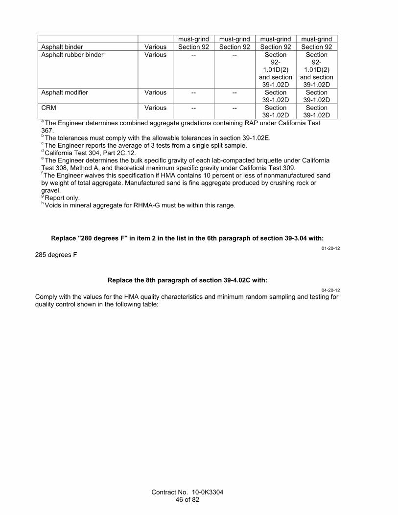
Contract No. 10-0K3304 46 of 82
must-grind must-grind must-grind must-grind Asphalt binder Various Section 92 Section 92 Section 92 Section 92 Asphalt rubber binder Various -- -- Section
92-1.01D(2)
and section 39-1.02D
Section 92-
1.01D(2) and section 39-1.02D
Asphalt modifier Various -- -- Section 39-1.02D
Section 39-1.02D
CRM Various -- -- Section 39-1.02D
Section 39-1.02D
a The Engineer determines combined aggregate gradations containing RAP under California Test 367. b The tolerances must comply with the allowable tolerances in section 39-1.02E. c The Engineer reports the average of 3 tests from a single split sample. d California Test 304, Part 2C.12. e The Engineer determines the bulk specific gravity of each lab-compacted briquette under California Test 308, Method A, and theoretical maximum specific gravity under California Test 309. f The Engineer waives this specification if HMA contains 10 percent or less of nonmanufactured sand by weight of total aggregate. Manufactured sand is fine aggregate produced by crushing rock or gravel. g Report only. h Voids in mineral aggregate for RHMA-G must be within this range.
Replace "280 degrees F" in item 2 in the list in the 6th paragraph of section 39-3.04 with:
01-20-12
285 degrees F
Replace the 8th paragraph of section 39-4.02C with:
04-20-12
Comply with the values for the HMA quality characteristics and minimum random sampling and testing for quality control shown in the following table:

Contract No. 10-0K3304 47 of 82
Minimum Quality Control—QC/QA Construction Process Quality
characteristic Test
method Minimum sampling
and testing
frequency
HMA Type
Location of
sampling
Maxi-mum report-ing time
allow-ance
A B RHMA-G
Aggregate gradationa
California Test 202
1 per 750 tons
JMF ± tolerance b
JMF ± tolerance b
JMF ± tolerance b
California Test 125
24 hours
Asphalt binder content (%)
California Test 379 or 382
JMF0.40 JMF0.40 JMF ±0.40
Loose mix
behind paver See
California Test 125
Field compaction (% max. theoretical density)c,d
QC plan 92–96 92–96 91–96 QC plan
Aggregate moisture content at continuous mixing plants and RAP moisture content at continuous mixing plants and batch mixing plantse
California Test 226 or 370
2 per day during
production -- -- --
Stock-piles or
cold feed belts
--
Sand equivalent (min) f
California Test 217
1 per 750 tons
47 42 47 California Test 125
24 hours
HMA moisture content (%,max)
California Test 226 or 370
1 per 2,500 tons
but not less
than 1 per paving
day
1.0 1.0 1.0
Loose Mix
Behind Paver See
California Test 125
24 hours
Stabilometer value (min)f,g
No. 4 and 3/8" gradings 1/2" and 3/4" gradings
California Test 366
1 per 4,000 tons or 2 per 5 business
days, whichever is greater
30
37
30
35
--
23
48 hours
Air void content (%)f,h
California Test 367
4 ± 2 4 ± 2 TV ± 2

Contract No. 10-0K3304 48 of 82
Percent of crushed particles coarse aggregate (% min.): One fractured face Two fractured faces Fine aggregate (% min) (Passing no. 4 sieve and retained on no. 8 sieve.): One fractured face
California Test 205
As desig-nated in QC plan.
At least
once per project.
90
75
70
25
--
20
--
90
70
California Test 125
48 hours
Los Angeles Rattler (% max): Loss at 100 rev. Loss at 500 rev.
California Test 211
12
45
--
50
12
40
California Test 125
Fine aggregate angularity (% min) i
California Test 234
45 45 45 California Test 125
Flat and elongated particle (% max by weight @ 5:1)
California Test 235
Report only
Report only
Report only
California Test 125
Voids filled with asphalt (%) j:
No. 4 grading 3/8" grading 1/2" grading 3/4" grading
California Test 367
65.0–75.0 65.0–75.0 65.0–75.0 65.0–75.0
65.0–75.0 65.0–75.0 65.0–75.0 65.0–75.0
Report only
Voids in mineral aggregate (% min.) j:
No. 4 grading 3/8" grading 1/2" grading 3/4" grading
California Test 367
17.0 15.0 14.0 13.0
17.0 15.0 14.0 13.0
-- --
18.0–23.0k
18.0–23.0k

Contract No. 10-0K3304 49 of 82
Dust proportion j: No. 4 and 3/8" gradings 1/2" and 3/4" gradings
California Test 367
0.6-1.2
0.6–1.2
0.6-1.2
0.6–1.2
Report only
Smoothness
Section 39-1.12
--
12-foot straight-edge, must-
grind, and PI0
12-foot straight-edge, must-
grind, and PI0
12-foot straight-edge, must-
grind, and PI0
--
Asphalt rubber binder viscosity @ 375 °F, centipoises
Section 39-1.02D
-- -- -- 1,500–4,000
Section 39-1.02D
24 hours
CRM Section 39-1.02D
-- -- -- Section 39-1.02D
Section 39-1.02D
48 hours
a Determine combined aggregate gradation containing RAP under California Test 367. b The tolerances must comply with the allowable tolerances in section 39-1.02E. c Determines field compaction for any of the following conditions:
1. 1/2-inch, 3/8-inch, or no. 4 aggregate grading is used and the specified total paved thickness is at least 0.15 foot.2. 3/4-inch aggregate grading is used and the specified total paved thickness is at least 0.20 foot.
d To determine field compaction use: 1. In-place density measurements using the method specified in your QC plan. 2. California Test 309 to determine the maximum theoretical density at the frequency specified in California Test 375, Part 5C.
e For adjusting the plant controller at the HMA plant. f Report the average of 3 tests from a single split sample. g California Test 304, Part 2C,12. h Determine the bulk specific gravity of each lab-compacted briquette under California Test 308, Method A, and theoretical maximum specific gravity under California Test 309. i The Engineer waives this specification if HMA contains 10 percent or less of nonmanufactured sand by weight of total aggregate. Manufactured sand is fine aggregate produced by crushing rock or gravel. j Report only. k Voids in mineral aggregate for RHMA-G must be within this range.
Replace the 1st sentence in the 1st paragraph of section 39-4.03B(2) with:
01-20-12
For aggregate gradation and asphalt binder content, the minimum ratio of verification testing frequency to quality control testing frequency is 1:5.
Replace the 2nd "and" in the 7th paragraph of section 39-4.03B(2) with:
01-20-12
or

Contract No. 10-0K3304 50 of 82
Replace the 1st paragraph of section 39-4.04A with:
04-20-12
The Engineer samples for acceptance testing and tests for the following quality characteristics:
HMA Acceptance—QC/QA Construction ProcessIndex
(i) Quality characteristic Weight-
ing factor
(w)
Test method
HMA type
A B RHMA-G
Aggregate gradation a
California Test 202
JMF ± Tolerance c
Sieve
3/4" 1/2" 3/8"
1 1/2" X b -- -- 0.05 1 3/8" -- X -- 0.05 1 No. 4 -- -- X 0.05 2 No. 8 X X X 0.10 3 No.
200 X X X 0.15
4 Asphalt binder content (%) 0.30 California Test 379 or 382
JMF0.40 JMF0.40 JMF ± 0.40
5 Field compaction (% max. theoretical density) d, e
0.40 California Test 375
92–96 92–96 91–96
Sand equivalent (min) f California Test 217
47 42 47
Stabilometer value (min) f,g No. 4 and 3/8" gradings 1/2" and 3/4" gradings
California Test 366
30 37
30 35
-- 23
Air void content (%)f, h California Test 367
4 ± 2 4 ± 2 TV ± 2
Percent of crushed particles coarse aggregate (% min)
One fractured face Two fractured faces
Fine aggregate (% min) (Passing no. 4 sieve and retained on No. 8 sieve.) One fractured face
California Test 205
90 75
70
25 --
20
-- 90
70
HMA moisture content (%, max)
California Test 226 or 370
1.0 1.0 1.0
Los Angeles Rattler (% max)
Loss at 100 rev. Loss at 500 rev.
California Test 211
12 45
-- 50
12 40
Fine aggregate angularity (% min)i
California Test 234
45 45 45
Flat and elongated particle (% max by weight @ 5:1)
California Test 235
Report only
Report only Report only
Voids in mineral aggregate (% min) j
No. 4 grading 3/8" grading 1/2" grading 3/4" grading
California Test 367
17.0 15.0 14.0 13.0
17.0 15.0 14.0 13.0
(Note k)
-- --
18.0–23.0
18.0–23.0

Contract No. 10-0K3304 51 of 82
Voids filled with asphalt (%)j
No. 4 grading 3/8" grading 1/2" grading 3/4" grading
California Test 367
65.0–75.0 65.0–75.0 65.0–75.0 65.0–75.0
65.0–75.0 65.0–75.0 65.0–75.0 65.0–75.0
Report only
Dust proportion j No. 4 and 3/8" gradings 1/2" and 3/4" gradings
California Test 367
0.6–1.2 0.6–1.2
0.6–1.2 0.6–1.2
Report only
Smoothness Section 39-1.12
12-foot straight-edge, must
grind, and PI0
12-foot straight-
edge, must grind, and
PI0
12-foot straight-
edge, must grind, and
PI0
Asphalt binder Various Section 92 Section 92 Section 92
Asphalt rubber binder Various -- --
Section 92-1.01D(2) and section 39-1.02D
Asphalt modifier Various -- --
Section 39-1.02D
CRM Various -- --
Section 39-1.02D
a The Engineer determines combined aggregate gradations containing RAP under California Test 367. b "X" denotes the sieves the Engineer tests for the specified aggregate gradation. c The tolerances must comply with the allowable tolerances in section 39-1.02E. d The Engineer determines field compaction for any of the following conditions:
1. 1/2-inch, 3/8-inch, or no. 4 aggregate grading is used and the specified total paved thickness is at least 0.15 foot and less than 0.20 foot.2. 3/4-inch aggregate grading is used and the specified total paved thickness is at least 0.20 foot.
e To determine field compaction, the Engineer uses: 1. California Test 308, Method A, to determine in-place density of each density core. 2. California Test 309 to determine the maximum theoretical density at the frequency specified in California Test 375, Part 5C.
f The Engineer reports the average of 3 tests from a single split sample. g California Test 304, Part 2C.12. h The Engineer determines the bulk specific gravity of each lab-compacted briquette under California Test 308, Method A, and theoretical maximum specific gravity under California Test 309. i The Engineer waives this specification if HMA contains 10 percent or less of nonmanufactured sand by weight of total aggregate. Manufactured sand is fine aggregate produced by crushing rock or gravel. j Report only. k Voids in mineral aggregate for RHMA-G must be within this range.
Replace the 3rd paragraph of section 39-4.04A with:
01-20-12
The Department determines the percent of maximum theoretical density from density cores taken from the final layer measured the full depth of the total paved HMA thickness if any of the following applies:
1. 1/2-inch, 3/8-inch, or no. 4 aggregate grading is used and the specified total paved thickness is at least 0.15 foot and any lager is less than 0.15 foot.
2. 3/4-inch aggregate grading is used and the specified total paved thickness is at least 0.20 and any layer is less than 0.20 foot.

Contract No. 10-0K3304 52 of 82
^^^^^^^^^^^^^^^^^^^^^^^^^^^^^^^^^^^^^^^^
40 CONCRETE PAVEMENT 01-20-12
Replace section 40-1.01C(4) with:
01-20-12
40-1.01C(4) Authorized Laboratory
Submit for authorization the name of the laboratory you propose to use for testing the drilled core specimens for air content.
Replace the paragraph in section 40-1.01C(8) with:
01-20-12
Submit a plan for protecting concrete pavement during the initial 72 hours after paving when the forecasted minimum ambient temperature is below 40 degrees F.
01-20-12
Delete "determined under California Test 559" in section 40-1.01C(9).
Replace the 2nd and 3rd paragraphs in section 40-1.01D(4) with:
01-20-12
The QC plan must include details of corrective action to be taken if any process is out of control. As a minimum, a process is out of control if any of the following occurs:
1. For fine and coarse aggregate gradation, 2 consecutive running averages of 4 tests are outside the specification limits
2. For individual penetration or air content measurements: 2.1. One point falls outside the suspension limit line 2.2. Two points in a row fall outside the action limit line
Stop production and take corrective action for out of control processes or the Engineer rejects subsequent material.
Replace the 1st paragraph in section 40-1.01D(5) with:
01-20-12
Determine the minimum cementitious materials content. Use your value for minimum cementitious material content for MC in equation 1 and equation 2 of section 90-1.02B(3).
Replace the 1st sentence of the 3rd paragraph of section 40-1.01D(9) with:
01-20-12
Use a California profilograph to determine the concrete pavement profile.
Replace the title of the table in section 40-1.01D(13)(a) with:
01-20-12
Concrete Pavement Acceptance Testing
Contract No. 10-0K3304 53 of 82
Replace the 2nd and 3rd paragraphs in section 40-1.01D(13)(a) with:
01-20-12
Pavement smoothness may be accepted based on the Department's testing. A single test represents no more than 0.1 mile.
Acceptance of modulus of rupture, thickness, dowel bar and tie bar placement, coefficient of friction, smoothness, and air content, does not constitute final concrete pavement acceptance.
01-20-12
Delete item 4 in the list in the 2nd paragraph in section 40-1.01D(13)(c)(2).
Replace items 1 and 2 in the list in the 2nd paragraph in 40-1.01D(13)(d) with:
01-20-12
1. For tangents and horizontal curves having a centerline radius of curvature 2,000 feet or more, the PI0 must be at most 2-1/2 inches per 0.1-mile section.
2. For horizontal curves having a centerline radius of curvature from 1,000 to 2,000 feet including concrete pavement within the superelevation transitions of those curves, the PI0 must be at most 5 inches per 0.1-mile section.
Replace the 1st and 2nd variables in the equation in section 40-1.01D(13)(f) with:
01-20-12
nc = Number of your quality control tests (minimum of 6 required) nv = Number of verification tests (minimum of 2 required)
Replace "Your approved third party independent testing laboratory" in the 4th paragraph of section 40-1.01D(13)(f) with:
01-20-12
The authorized laboratory
Replace item 2 in the list in the 2nd paragraph of section 40-1.01D(13)(g):
01-20-12
2. One test for every 4,000 square yards of concrete pavement with tie bars or remaining fraction of that area. Each tie bar test consists of 2 cores with 1 on each tie-bar-end to expose both ends and allow measurement.
Replace section 40-1.01D(13)(h) with:
01-20-12
40-1.01D(13)(h) Bar Reinforcement
Bar reinforcement is accepted based on inspection before concrete placement.
Replace the paragraph in section 40-1.02B(2) with:
01-20-12
PCC for concrete pavement must comply with section 90-1 except as otherwise specified.

Contract No. 10-0K3304 54 of 82
Replace the paragraphs in section 40-1.02D with:
01-20-12
Bar reinforcement must be deformed bars.
If the project is not shown to be in high desert or any mountain climate region, bar reinforcement must comply with section 52.
If the project is shown to be in high desert or any mountain climate regions, bar reinforcement must be one of the following:
1. Epoxy-coated bar reinforcement under section 52-2.03B except bars must comply with either ASTM A 706/A 706M; ASTM A 996/A 996M; or ASTM A 615/A 615M, Grade 40 or 60. Bars must be handled under ASTM D 3963/D 3963M and section 52-2.02C.
2. Low carbon, chromium steel bar complying with ASTM A 1035/A 1035M
Replace the paragraphs in section 40-1.02E with:
01-20-12
Tie bars must be deformed bars.
If the project is not shown to be in high desert or any mountain climate region, tie bars must be one of the following:
1. Epoxy-coated bar reinforcement. Bars must comply with either section 52-2.02B or 52-2.03B except bars must comply with either ASTM A 706/A 706M; ASTM A 996/A 996M; or ASTM A 615/A 615M, Grade 40 or 60.
2. Stainless-steel bars. Bars must be descaled, pickled, polished, and solid stainless-steel bars under ASTM A 955/A 955M, Grade 60, UNS Designation S31603 or S31803.
3. Low carbon, chromium-steel bars under ASTM A 1035/A 1035M. If the project is shown to be in high desert or any mountain climate region, tie bars must be one of the following:
1. Epoxy-coated bar reinforcement. Bars must comply with section 52-2.03B except bars must comply with either ASTM A 706/A 706M; ASTM A 996/A 996M; or ASTM A 615/A 615M, Grade 40 or 60.
2. Stainless-steel bars. Bars must be descaled, pickled, polished, and solid stainless-steel bars under ASTM A 955/A 955M, Grade 60, UNS Designation S31603 or S31803.
Fabricate, sample, and handle epoxy-coated tie bars under ASTM D 3963/D 3963M, section 52-2.02C, or section 52-2.03C.
Do not bend tie bars.
Replace the 1st, 2nd, and 3rd paragraphs in section 40-1.02F with:
01-20-12
Dowel bars must be plain bars. Fabricate, sample, and handle epoxy-coated dowel bars under ASTM D 3963/D 3963M and section 52-2.03C except each sample must be 18 inches long.
If the project is not shown to be in high desert or any mountain climate region, dowel bars must be one of the following:
1. Epoxy-coated bars. Bars must comply with ASTM A 615/A 615M, Grade 40 or 60. Epoxy coating must comply with either section 52-2.02B or 52-2.03B.
2. Stainless-steel bars. Bars must be descaled, pickled, polished, and solid stainless-steel bars under ASTM A 955/A 955M, Grade 60, UNS Designation S31603 or S31803.
3. Low carbon, chromium-steel bars under ASTM A 1035/A 1035M. If the project is shown to be in high desert or any mountain climate region, dowel bars must be one of the following:

Contract No. 10-0K3304 55 of 82
1. Epoxy-coated bars. Bars must comply with ASTM A 615/A 615M, Grade 40 or 60. Epoxy coating must comply with section 52-2.03B.
2. Stainless-steel bars. Bars must be descaled, pickled, polished, and solid stainless-steel bars under ASTM A 955/A 955M, Grade 60, UNS Designation S31603 or S31803.
Replace the paragraphs in section 40-1.02G with:
01-20-12
For dowel and tie bar baskets, wire must comply with ASTM A 82/A 82M and be welded under ASTM A 185/A 185M, Section 7.4. The minimum wire-size no. is W10. Use either U-frame or A-frame shaped assemblies.
If the project is not shown to be in high desert or any mountain climate region. Baskets may be epoxy-coated, and the epoxy coating must comply with either section 52-2.02B or 52-2.03B.
If the project is shown to be in high desert or any mountain climate region, wire for dowel bar and tie bar baskets must be one of the following:
1. Epoxy-coated wire complying with section 52-2.03B 2. Stainless-steel wire. Wire must be descaled, pickled, and polished solid stainless-steel. Wire must
comply with (1) the chemical requirements in ASTM A 276/A 276M, UNS Designation S31603 or S31803 and (2) the tension requirements in ASTM A 1022/ A 1022M.
Handle epoxy-coated tie bar and dowel bar baskets under ASTM D 3963/D 3963M and either section 52-2.02B or 52-2.03B.
Fasteners must be driven fasteners under ASTM F 1667. Fasteners on lean concrete base or HMA must have a minimum shank diameter of 3/16 inch and a minimum shank length of 2-1/2 inches. For asphalt treated permeable base or cement treated permeable base, the shank diameter must be at least 3/16 inch and the shank length must be at least 5 inches.
Fasteners, clips, and washers must have a minimum 0.2-mil thick zinc coating applied by either electroplating or galvanizing.
Replace the 1st paragraph in section 40-1.02H with:
01-20-12
Chemical adhesive for drilling and bonding dowels and tie bars must be on the Authorized Material List. The Authorized Material List indicates the appropriate chemical adhesive system for the concrete temperature and installation conditions.
Replace section 40-1.02I(2) with:
01-20-12
40-1.02I(2) Silicone Joint Sealant
Silicone joint sealant must be on the Authorized Material List.
Replace the last sentence in section 40-1.02I(4) with:
01-20-12
Show evidence that the seals are compressed from 30 to 50 percent for the joint width at time of installation.

Contract No. 10-0K3304 56 of 82
Replace the paragraph in section 40-1.02L with:
01-20-12
Water for core drilling may be obtained from a potable water source, or submit proof that it does not contain:
1. More than 1,000 parts per million of chlorides as Cl 2. More than 1,300 parts per million of sulfates as S04 3. Impurities that cause pavement discoloration or surface etching
Replace the paragraph in section 40-1.03B with:
01-20-12
Before placing concrete pavement, develop enough water supply for the work under section 17.
Replace the last paragraph in section 40-1.03D(1) with:
01-20-12
Removal of grinding residue must comply with section 42-1.03B.
Replace the 1st and 2nd paragraphs in section 40-1.03E(6)(c) with:
01-20-12
Install preformed compressions seals in isolation joints if specified in the special provisions.
Install longitudinal seals before transverse seals. Longitudinal seals must be continuous except splicing is allowed at intersections with transverse seals. Transverse seals must be continuous for the entire transverse length of concrete pavement except splices are allowed for widenings and staged construction. With a sharp instrument, cut across the longitudinal seal at the intersection with transverse construction joints. If the longitudinal seal does not relax enough to properly install the transverse seal, trim the longitudinal seal to form a tight seal between the 2 joints.
If splicing is authorized, splicing must comply with the manufacturer's written instructions.
Replace the last 2 paragraphs in section 40-1.03G with:
01-20-12
Construct additional test strips if you:
1. Propose different paving equipment including: 1.1. Paver 1.2. Dowel bar inserter 1.3. Tie bar inserter 1.4. Tining 1.5. Curing equipment
2. Change concrete mix proportions You may request authorization to eliminate the test strip if you use paving equipment and personnel from a Department project (1) for the same type of pavement and (2) completed within the past 12 months. Submit supporting documents and previous project information with your request.
Replace the 1st paragraph in section 40-1.03I with:
01-20-12
Place tie bars in compliance with the tolerances shown in the following table:
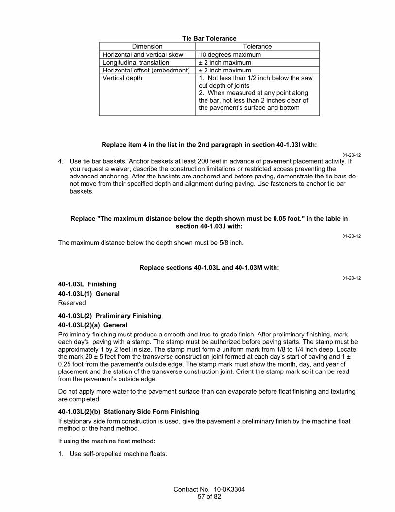
Contract No. 10-0K3304 57 of 82
Tie Bar ToleranceDimension Tolerance
Horizontal and vertical skew 10 degrees maximumLongitudinal translation ± 2 inch maximumHorizontal offset (embedment) ± 2 inch maximumVertical depth 1. Not less than 1/2 inch below the saw
cut depth of joints 2. When measured at any point along the bar, not less than 2 inches clear of the pavement's surface and bottom
Replace item 4 in the list in the 2nd paragraph in section 40-1.03I with:
01-20-12
4. Use tie bar baskets. Anchor baskets at least 200 feet in advance of pavement placement activity. If you request a waiver, describe the construction limitations or restricted access preventing the advanced anchoring. After the baskets are anchored and before paving, demonstrate the tie bars do not move from their specified depth and alignment during paving. Use fasteners to anchor tie bar baskets.
Replace "The maximum distance below the depth shown must be 0.05 foot." in the table in section 40-1.03J with:
01-20-12
The maximum distance below the depth shown must be 5/8 inch.
Replace sections 40-1.03L and 40-1.03M with:
01-20-12
40-1.03L Finishing
40-1.03L(1) General
Reserved
40-1.03L(2) Preliminary Finishing
40-1.03L(2)(a) General
Preliminary finishing must produce a smooth and true-to-grade finish. After preliminary finishing, mark each day's paving with a stamp. The stamp must be authorized before paving starts. The stamp must be approximately 1 by 2 feet in size. The stamp must form a uniform mark from 1/8 to 1/4 inch deep. Locate the mark 20 ± 5 feet from the transverse construction joint formed at each day's start of paving and 1 ± 0.25 foot from the pavement's outside edge. The stamp mark must show the month, day, and year of placement and the station of the transverse construction joint. Orient the stamp mark so it can be read from the pavement's outside edge.
Do not apply more water to the pavement surface than can evaporate before float finishing and texturing are completed.
40-1.03L(2)(b) Stationary Side Form Finishing
If stationary side form construction is used, give the pavement a preliminary finish by the machine float method or the hand method.
If using the machine float method:
1. Use self-propelled machine floats.

Contract No. 10-0K3304 58 of 82
2. Determine the number of machine floats required to perform the work at a rate equal to the pavement delivery rate. If the time from paving to machine float finishing exceeds 30 minutes, stop pavement delivery. When machine floats are in proper position, you may resume pavement delivery and paving.
3. Run machine floats on side forms or adjacent pavement lanes. If running on adjacent pavement, protect the adjacent pavement surface under section 40-1.03P. Floats must be hardwood, steel, or steel-shod wood. Floats must be equipped with devices that adjust the underside to a true flat surface.
If using the hand method, finish pavement smooth and true to grade with manually operated floats or powered finishing machines.
40-1.03L(2)(c) Slip-Form Finishing
If slip-form construction is used, the slip-form paver must give the pavement a preliminary finish. You may supplement the slip-form paver with machine floats.
Before the pavement hardens, correct pavement edge slump in excess of 0.02 foot exclusive of edge rounding.
40-1.03L(3) Final Finishing
After completing preliminary finishing, round the edges of the initial paving widths to a 0.04-foot radius. Round transverse and longitudinal construction joints to a 0.02-foot radius.
Before curing, texture the pavement. Perform initial texturing with a burlap drag or broom device that produces striations parallel to the centerline. Perform final texturing with a steel-tined device that produces grooves parallel with the centerline.
Construct longitudinal grooves with a self-propelled machine designed specifically for grooving and texturing pavement. The machine must have tracks to maintain constant speed, provide traction, and maintain accurate tracking along the pavement surface. The machine must have a single row of rectangular spring steel tines. The tines must be from 3/32 to 1/8 inch wide, on 3/4-inch centers, and must have enough length, thickness, and resilience to form grooves approximately 3/16 inch deep. The machine must have horizontal and vertical controls. The machine must apply constant down pressure on the pavement surface during texturing. The machines must not cause ravels.
Construct grooves over the entire pavement width in a single pass except do not construct grooves 3 inches from the pavement edges and longitudinal joints. Final texture must be uniform and smooth. Use a guide to properly align the grooves. Grooves must be parallel and aligned to the pavement edge across the pavement width. Grooves must be from 1/8 to 3/16 inch deep after the pavement has hardened.
For irregular areas and areas inaccessible to the grooving machine, you may hand-construct grooves under section 40-1.03L(2) using the hand method. Hand-constructed grooves must comply with the specifications for machine-constructed grooves.
Initial and final texturing must produce a coefficient of friction of at least 0.30 when tested under California Test 342. Notify the Engineer when the pavement is scheduled to be opened to traffic to allow at least 25 days for the Department to schedule testing for coefficient of friction. Notify the Engineer when the pavement is ready for testing which is the latter of:
1. Seven days after paving 2. When the pavement has attained a modulus of rupture of 550 psi The Department tests for coefficient of friction within 7 days of receiving notification that the pavement is ready for testing.
Do not open the pavement to traffic unless the coefficient of friction is at least 0.30.
40-1.03M Reserved
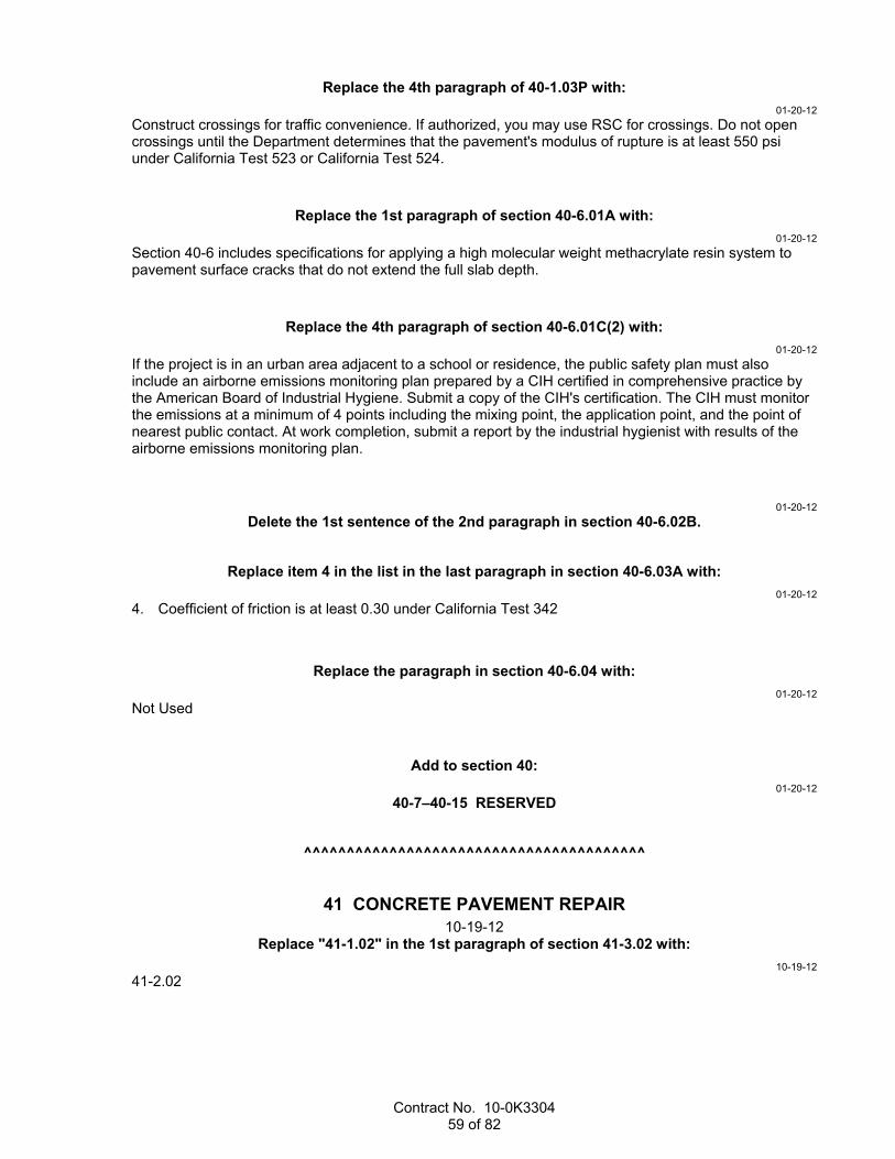
Contract No. 10-0K3304 59 of 82
Replace the 4th paragraph of 40-1.03P with:
01-20-12
Construct crossings for traffic convenience. If authorized, you may use RSC for crossings. Do not open crossings until the Department determines that the pavement's modulus of rupture is at least 550 psi under California Test 523 or California Test 524.
Replace the 1st paragraph of section 40-6.01A with:
01-20-12
Section 40-6 includes specifications for applying a high molecular weight methacrylate resin system to pavement surface cracks that do not extend the full slab depth.
Replace the 4th paragraph of section 40-6.01C(2) with:
01-20-12
If the project is in an urban area adjacent to a school or residence, the public safety plan must also include an airborne emissions monitoring plan prepared by a CIH certified in comprehensive practice by the American Board of Industrial Hygiene. Submit a copy of the CIH's certification. The CIH must monitor the emissions at a minimum of 4 points including the mixing point, the application point, and the point of nearest public contact. At work completion, submit a report by the industrial hygienist with results of the airborne emissions monitoring plan.
01-20-12
Delete the 1st sentence of the 2nd paragraph in section 40-6.02B.
Replace item 4 in the list in the last paragraph in section 40-6.03A with:
01-20-12
4. Coefficient of friction is at least 0.30 under California Test 342
Replace the paragraph in section 40-6.04 with:
01-20-12
Not Used
Add to section 40:
01-20-12
40-7–40-15 RESERVED
^^^^^^^^^^^^^^^^^^^^^^^^^^^^^^^^^^^^^^^^
41 CONCRETE PAVEMENT REPAIR 10-19-12
Replace "41-1.02" in the 1st paragraph of section 41-3.02 with:
10-19-12
41-2.02
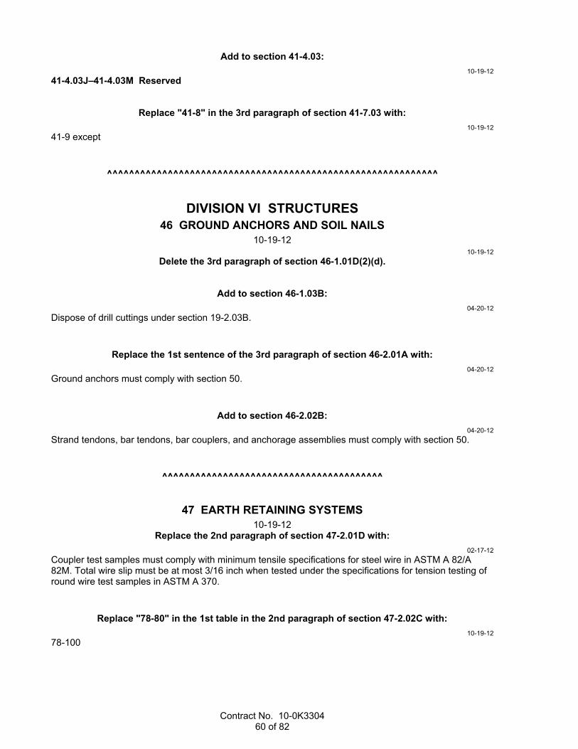
Contract No. 10-0K3304 60 of 82
Add to section 41-4.03:
10-19-12
41-4.03J–41-4.03M Reserved
Replace "41-8" in the 3rd paragraph of section 41-7.03 with:
10-19-12
41-9 except
^^^^^^^^^^^^^^^^^^^^^^^^^^^^^^^^^^^^^^^^^^^^^^^^^^^^^^^^^^^^
DIVISION VI STRUCTURES 46 GROUND ANCHORS AND SOIL NAILS
10-19-12 10-19-12
Delete the 3rd paragraph of section 46-1.01D(2)(d).
Add to section 46-1.03B:
04-20-12
Dispose of drill cuttings under section 19-2.03B.
Replace the 1st sentence of the 3rd paragraph of section 46-2.01A with:
04-20-12
Ground anchors must comply with section 50.
Add to section 46-2.02B:
04-20-12
Strand tendons, bar tendons, bar couplers, and anchorage assemblies must comply with section 50.
^^^^^^^^^^^^^^^^^^^^^^^^^^^^^^^^^^^^^^^^
47 EARTH RETAINING SYSTEMS 10-19-12
Replace the 2nd paragraph of section 47-2.01D with:
02-17-12
Coupler test samples must comply with minimum tensile specifications for steel wire in ASTM A 82/A 82M. Total wire slip must be at most 3/16 inch when tested under the specifications for tension testing of round wire test samples in ASTM A 370.
Replace "78-80" in the 1st table in the 2nd paragraph of section 47-2.02C with:
10-19-12
78-100

Contract No. 10-0K3304 61 of 82
Replace the value for the sand equivalent requirement in the 2nd table in the 3rd paragraph of section 47-2.02C with:
01-20-12
12 minimum
Replace the 1st paragraph of section 47-2.02E with:
02-17-12
Steel wire must comply with ASTM A 82/A 82M. Welded wire reinforcement must comply with ASTM A 185/A 185M.
Add between the 2nd and 3rd paragraphs of section 47-3.02A:
10-19-12
Reinforcement must comply with section 52.
10-19-12
Delete the 1st paragraph of section 47-3.02B(2)(b).
Add between the 3rd and 4th paragraphs of section 47-5.01:
10-19-12
Reinforcement must comply with section 52.
Add to section 47-6.01A:
10-19-12
The alternative earth retaining system must comply with the specifications for the type of wall being constructed.
^^^^^^^^^^^^^^^^^^^^^^^^^^^^^^^^^^^^^^^^
48 TEMPORARY STRUCTURES 09-16-11
Replace the 7th paragraph of section 48-2.01C(2) with:
09-16-11
If you submit multiple submittals at the same time or additional submittals before review of a previous submittal is complete:
1. You must designate a review sequence for submittals 2. Review time for any submittal is the review time specified plus 15 days for each submittal of higher
priority still under review
^^^^^^^^^^^^^^^^^^^^^^^^^^^^^^^^^^^^^^^^

Contract No. 10-0K3304 62 of 82
49 PILING 10-19-12
Replace "Load Applied to Pile by Hydraulic Jack(s) Acting at One End of Test Beam(s) Anchored to the Pile" in the 5th paragraph of section 49-1.01D(2) with:
07-20-12
"Tensile Load Applied by Hydraulic Jack(s) Acting Upward at One End of Test Beam(s)"
Add to section 49-1.03:
04-20-12
Dispose of drill cuttings under section 19-2.03B.
Replace the 2nd paragraph of section 49-2.01D with:
01-20-12
Furnish piling is measured along the longest side of the pile from the specified tip elevation shown to the plane of pile cutoff.
Replace the 3rd and 4th paragraphs of section 49-2.04B(2) with:
10-19-12
Piles in a corrosive environment must be steam or water cured under section 90-4.03.
If piles in a corrosive environment are steam cured, either:
1. Keep the piles continuously wet for at least 3 days. The 3 days includes the holding and steam curing periods.
2. Apply curing compound under section 90-1.03B(3) after steam curing.
Add to section 49-3.01A:
01-20-12
Concrete must comply with section 51.
Replace the 1st paragraph of section 49-3.01C with:
01-20-12
Except for CIDH concrete piles constructed under slurry, construct CIP concrete piles such that the excavation methods and the concrete placement procedures provide for placing the concrete against undisturbed material in a dry or dewatered hole.
Replace "Reserved" in section 49-3.02A(2) with:
01-20-12
dry hole:
1. Except for CIDH concrete piles specified as end bearing, a drilled hole that: 1.1. Accumulates no more than 12 inches of water in the bottom of the drilled hole during a period
of 1 hour without any pumping from the hole during the hour. 1.2. Has no more than 3 inches of water in the bottom of the drilled hole immediately before placing
concrete. 2. For CIDH concrete piles specified as end bearing, a drilled hole free of water without the use of
pumps.

Contract No. 10-0K3304 63 of 82
Replace "Reserved" in section 49-3.02A(3)(a) with:
01-20-12
If plastic spacers are proposed for use, submit the manufacturer's data and a sample of the plastic spacer. Allow 10 days for review.
Replace item 5 in the list in the 1st paragraph of section 49-3.02A(3)(b) with:
10-19-12
5. Methods and equipment for determining: 5.1. Depth of concrete 5.2. Theoretical volume of concrete to be placed, including the effects on volume if casings are
withdrawn 5.3. Actual volume of concrete placed
Replace item 2 in the list in the 1st paragraph of section 49-3.02A(3)(g) with:
01-20-12
2. Be sealed and signed by an engineer who is registered as a civil engineer in the State. This requirement is waived for either of the following conditions: 2.1. The proposed mitigation will be performed under the current Department-published version of
ADSC Standard Mitigation Plan 'A' - Basic Repair without exception or modification. 2.2. The Engineer determines that the rejected pile does not require mitigation due to structural,
geotechnical, or corrosion concerns, and you elect to repair the pile using the current Department-published version of ADSC Standard Mitigation Plan 'B' - Grouting Repair without exception or modification.
Replace item 1 in the list in the 1st paragraph of section 49-3.02A(4)(d)(ii) with:
01-20-12
1. Inspection pipes must be schedule 40 PVC pipe complying with ASTM D 1785 with a nominal pipe size of 2 inches. Watertight PVC couplers complying with ASTM D 2466 are allowed to facilitate pipe lengths in excess of those commercially available. Log the location of the inspection pipe couplers with respect to the plane of pile cutoff.
Add to section 49-3.02A(4)(d)(iv):
01-20-12
If the Engineer determines it is not feasible to use one of ADSC's standard mitigation plans to mitigate the pile, schedule a meeting and meet with the Engineer before submitting a nonstandard mitigation plan.
The meeting attendees must include your representatives and the Engineer's representatives involved in the pile mitigation. The purpose of the meeting is to discuss the type of pile mitigation acceptable to the Department.
Provide the meeting facility. The Engineer conducts the meeting.
Replace the 1st paragraph of section 49-3.02B(5) with:
01-20-12
Grout used to backfill casings must comply with section 50-1.02C, except:
1. Grout must consist of cementitious material and water, and may contain an admixture if authorized. Cementitious material must comply with section 90-1.02B, except SCMs are not required. The minimum cementitious material content of the grout must not be less than 845 lb/cu yd of grout.
2. Aggregate must be used to extend the grout as follows:
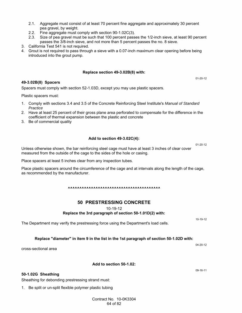
Contract No. 10-0K3304 64 of 82
2.1. Aggregate must consist of at least 70 percent fine aggregate and approximately 30 percent pea gravel, by weight.
2.2. Fine aggregate must comply with section 90-1.02C(3). 2.3. Size of pea gravel must be such that 100 percent passes the 1/2-inch sieve, at least 90 percent
passes the 3/8-inch sieve, and not more than 5 percent passes the no. 8 sieve. 3. California Test 541 is not required. 4. Grout is not required to pass through a sieve with a 0.07-inch maximum clear opening before being
introduced into the grout pump.
Replace section 49-3.02B(8) with:
01-20-12
49-3.02B(8) Spacers
Spacers must comply with section 52-1.03D, except you may use plastic spacers.
Plastic spacers must:
1. Comply with sections 3.4 and 3.5 of the Concrete Reinforcing Steel Institute's Manual of Standard Practice
2. Have at least 25 percent of their gross plane area perforated to compensate for the difference in the coefficient of thermal expansion between the plastic and concrete
3. Be of commercial quality
Add to section 49-3.02C(4):
01-20-12
Unless otherwise shown, the bar reinforcing steel cage must have at least 3 inches of clear cover measured from the outside of the cage to the sides of the hole or casing.
Place spacers at least 5 inches clear from any inspection tubes.
Place plastic spacers around the circumference of the cage and at intervals along the length of the cage, as recommended by the manufacturer.
^^^^^^^^^^^^^^^^^^^^^^^^^^^^^^^^^^^^^^^^
50 PRESTRESSING CONCRETE 10-19-12
Replace the 3rd paragraph of section 50-1.01D(2) with:
10-19-12
The Department may verify the prestressing force using the Department's load cells.
Replace "diameter" in item 9 in the list in the 1st paragraph of section 50-1.02D with:
04-20-12
cross-sectional area
Add to section 50-1.02:
09-16-11
50-1.02G Sheathing
Sheathing for debonding prestressing strand must:
1. Be split or un-split flexible polymer plastic tubing

Contract No. 10-0K3304 65 of 82
2. Have a minimum wall thickness of 0.025 inch 3. Have an inside diameter exceeding the maximum outside diameter of the strand by 0.025 to 0.14 inch Split sheathing must overlap at least 3/8 inch.
Waterproofing tape used to seal the ends of the sheathing must be flexible adhesive tape.
The sheathing and waterproof tape must not react with the concrete, coating, or steel.
Add to section 50-1.03B(1):
01-20-12
After seating, the maximum tensile stress in the prestressing steel must not exceed 75 percent of the minimum ultimate tensile strength shown.
Add to section 50-1.03B(2):
09-16-11
50-1.03B(2)(e) Debonding Prestressing Strands
Where shown, debond prestressing strands by encasing the strands in plastic sheathing along the entire length shown and sealing the ends of the sheathing with waterproof tape.
Distribute the debonded strands symmetrically about the vertical centerline of the girder. The debonded lengths of pairs of strands must be equal.
Do not terminate debonding at any one cross section of the member for more than 40 percent of the debonded strands or 4 strands, whichever is greater.
Thoroughly seal the ends with waterproof tape to prevent the intrusion of water or cement paste before placing the concrete.
^^^^^^^^^^^^^^^^^^^^^^^^^^^^^^^^^^^^^^^^
51 CONCRETE STRUCTURES 10-19-12
Add to section 51:
10-19-12
51-8–51-15 RESERVED
Replace the paragraphs of section 51-1.01A with:
10-19-12
Section 51-1 includes general specifications for constructing concrete structures.
Earthwork for the following concrete structures must comply with section 19-3:
1. Sound wall footings 2. Sound wall pile caps 3. Culverts 4. Barrier slabs 5. Junction structures 6. Minor structures 7. Pipe culvert headwalls, endwalls, and wingwalls for a pipe with a diameter of 5 feet or greater Falsework must comply with section 48-2.
Joints must comply with section 51-2.

Contract No. 10-0K3304 66 of 82
Elastomeric bearing pads must comply with section 51-3.
Reinforcement for the following concrete structures must comply with section 52:
1. Sound wall footings 2. Sound wall pile caps 3. Barrier slabs 4. Junction structures 5. Minor structures 6. PC concrete members You may use RSC for a concrete structure only where the specifications allow the use of RSC.
Add to section 51-1.03C(2)(c)(i):
04-20-12
Permanent steel deck forms are only allowed where shown or if specified as an option in the special provisions.
Replace the 3rd paragraph of section 51-1.03C(2)(c)(ii) with:
04-20-12
Compute the physical design properties under AISI's North American Specification for the Design of Cold-Formed Steel Structural Members.
Replace the 8th paragraph of section 51-1.03D(1) with:
10-19-12
Except for concrete placed as pipe culvert headwalls and endwalls, slope paving and aprons, and concrete placed under water, consolidate concrete using high-frequency internal vibrators within 15 minutes of placing concrete in the forms. Do not attach vibrators to or hold them against forms or reinforcing steel. Do not displace reinforcement, ducts, or prestressing steel during vibrating.
Add to section 51-1.03E(5):
08-05-11
Drill the holes without damaging the adjacent concrete. If reinforcement is encountered during drilling before the specified depth is attained, notify the Engineer. Unless coring through the reinforcement is authorized, drill a new hole adjacent to the rejected hole to the depth shown.
Replace "Reserved" in section 51-1.03F(5)(b) with:
04-20-12
51-1.03F(5)(b)(i) General
Except for bridge widenings, texture the bridge deck surfaces longitudinally by grinding and grooving or by longitudinal tining.
10-19-12
For bridge widenings, texture the deck surface longitudinally by longitudinal tining.
04-20-12
In freeze-thaw areas, do not texture PCC surfaces of bridge decks.
51-1.03F(5)(b)(ii) Grinding and Grooving
When texturing the deck surface by grinding and grooving, place a 1/4 inch of sacrificial concrete cover on the bridge deck above the finished grade shown. Place items to be embedded in the concrete based

Contract No. 10-0K3304 67 of 82
on the final profile grade elevations shown. Construct joint seals after completing the grinding and grooving.
Before grinding and grooving, deck surfaces must comply with the smoothness and deck crack treatment requirements.
Grind and groove the deck surface as follows:
1. Grind the surface to within 18 inches of the toe of the barrier under section 42-3. Grinding must not reduce the concrete cover on reinforcing steel to less than 1-3/4 inches.
2. Groove the ground surfaces longitudinally under section 42-2. The grooves must be parallel to the centerline.
51-1.03F(5)(b)(iii) Longitudinal Tining
When texturing the deck surface by longitudinal tining, perform initial texturing with a burlap drag or broom device that produces striations parallel to the centerline. Perform final texturing with spring steel tines that produce grooves parallel with the centerline.
The tines must:
1. Be rectangular in cross section 2. Be from 3/32 to 1/8 inch wide on 3/4-inch centers 3. Have enough length, thickness, and resilience to form grooves approximately 3/16 inch deep Construct grooves to within 6 inches of the layout line of the concrete barrier toe. Grooves must be from 1/8 to 3/16 inch deep and 3/16 inch wide after concrete has hardened.
For irregular areas and areas inaccessible to the grooving machine, you may hand construct grooves. Hand-constructed grooves must comply with the specifications for machine-constructed grooves.
Tining must not cause tearing of the deck surface or visible separation of coarse aggregate at the surface.
Replace the paragraphs of section 51-1.04 with:
10-19-12
If concrete involved in bridge work is not designated by type and is not otherwise paid for under a separate bid item, the concrete is paid for as structural concrete, bridge.
The payment quantity for structural concrete includes the volume in the concrete occupied by bar reinforcing steel, structural steel, prestressing steel materials, and piling.
The payment quantity for seal course concrete is the actual volume of seal course concrete placed except the payment quantity must not exceed the volume of concrete contained between vertical planes 1 foot outside the neat lines of the seal course shown. The Department does not adjust the unit price for an increase or decrease in the seal course concrete quantity.
Structural concrete for pier columns is measured as follows:
1. Horizontal limits are vertical planes at the neat lines of the pier column shown. 2. Bottom limit is the bottom of the foundation excavation in the completed work. 3. Upper limit is the top of the pier column concrete shown. The payment quantity for drill and bond dowel is determined from the number and depths of the holes shown.
Replace "SSPC-QP 3" in the 1st paragraph of section 51-2.02A(2) with:
10-19-12
AISC-420-10/SSPC-QP 3

Contract No. 10-0K3304 68 of 82
Replace the 2nd and 3rd paragraphs of section 51-2.02B(3)(b) with:
04-20-12
Concrete saws for cutting grooves in the concrete must have diamond blades with a minimum thickness of 3/16 inch. Cut both sides of the groove simultaneously for a minimum 1st pass depth of 2 inches. The completed groove must have:
1. Top width within 1/8 inch of the width shown or ordered 2. Bottom width not varying from the top width by more than 1/16 inch for each 2 inches of depth 3. Uniform width and depth Cutting grooves in existing decks includes cutting any conflicting reinforcing steel.
Replace the 2nd paragraph of section 51-2.02E(1)(e) with:
08-05-11
Except for components in contact with the tires, the design loading must be the AASHTO LRFD Bridge Design Specifications Design Truck with 100 percent dynamic load allowance. Each component in contact with the tires must support a minimum of 80 percent of the AASHTO LRFD Bridge Design Specifications Design Truck with 100 percent dynamic load allowance. The tire contact area must be 10 inches measured normal to the longitudinal assembly axis by 20 inches wide. The assembly must provide a smooth-riding joint without slapping of components or tire rumble.
Add between the 1st and 2nd paragraphs of section 51-4.01A:
10-19-12
Prestressing concrete members must comply with section 50.
04-20-12
Delete the 2nd paragraph of section 51-4.01A.
Replace the 3rd paragraph of section 51-4.01C(2) with:
04-20-12
For segmental or spliced-girder construction, shop drawings must include the following additional information:
1. Details showing construction joints or closure joints 2. Arrangement of bar reinforcing steel, prestressing tendons, and pressure-grouting pipe 3. Materials and methods for making closures 4. Construction joint keys and surface treatment 5. Other requested information For segmental girder construction, shop drawings must include concrete form and casting details.
10-19-12
Delete the 1st and 2nd paragraphs of section 51-4.02A.
Replace the 3rd paragraph of section 51-4.02B(2) with:
04-20-12
For segmental or spliced-girder construction, materials for construction joints or closure joints at exterior girders must match the color and texture of the adjoining concrete.

Contract No. 10-0K3304 69 of 82
Add to section 51-4.02B(2):
04-20-12
At spliced-girder closure joints:
1. If shear keys are not shown, the vertical surfaces of the girder segment ends must be given a coarse texture as specified for the top surface of PC members.
2. Post-tensioning ducts must extend out of the vertical surface of the girder segment closure end sufficiently to facilitate splicing of the duct.
For spliced girders, pretension strand extending from the closure end of the girder segment to be embedded in the closure joint must be free of mortar, oil, dirt, excessive mill scale and scabby rust, and other coatings that would destroy or reduce the bond.
Add to section 51-4.03B:
04-20-12
The specifications for prestressing force distribution and sequencing of stressing in the post-tensioning activity in 50-1.03B(2)(a) do not apply if post-tensioning of spliced girders before starting deck construction is described. The composite deck-girder structure must be post-tensioned in a subsequent stage.
Temporary spliced-girder supports must comply with the specifications for falsework in section 48-2.
Before post-tensioning of spliced girders, remove the forms at CIP concrete closures and intermediate diaphragms to allow inspection for concrete consolidation.
Add between the 1st and 2nd paragraphs of section 51-7.01A:
10-19-12
Minor structures include:
1. Pipe culvert headwalls and endwalls for a pipe with a diameter less than 5 feet 2. Drainage inlets 3. Other structures described as minor structures
10-19-12
Delete the 4th paragraph of section 51-7.01A.
Replace the 1st and 2nd paragraphs of section 51-7.01B with:
10-19-12
Concrete must comply with the specifications for minor concrete.
^^^^^^^^^^^^^^^^^^^^^^^^^^^^^^^^^^^^^^^^
52 REINFORCEMENT 10-19-12
Add to section 52-1.01A:
07-20-12
Splicing of bar reinforcement must comply with section 52-6.

Contract No. 10-0K3304 70 of 82
Replace the 1st and 2nd paragraphs of section 52-1.02B with:
10-19-12
Reinforcing bars must be deformed bars complying with ASTM A 706/A 706M, Grade 60, except you may use:
1. Deformed bars complying with ASTM A 615/A 615M, Grade 60, in: 1.1. Junction structures 1.2. Sign and signal foundations 1.3. Minor structures 1.4. Concrete crib members 1.5. Mechanically-stabilized-embankment concrete panels 1.6. Masonry block sound walls
2. Deformed or plain bars complying with ASTM A 615/A 615M, Grade 40 or 60, in: 2.1. Slope and channel paving 2.2. Concrete barriers Type 50 and 60
3. Plain bars for spiral or hoop reinforcement in structures and concrete piles
Add to the list in the 3rd paragraph of section 52-1.02B:
04-20-12
9. Shear reinforcement stirrups in PC girders
Replace section 52-6.02D with:
10-21-11
52-6.02D Ultimate Butt Splice Requirements
When tested under California Test 670, ultimate butt splice test samples must demonstrate necking as either of the following:
1. For "Necking (Option I)," the test sample must rupture in the reinforcing bar outside of the affected zone and show visible necking.
2. For "Necking (Option II)," the largest measured strain must be at least: 2.1. Six percent for no. 11 and larger bars 2.2. Nine percent for no. 10 and smaller bars
^^^^^^^^^^^^^^^^^^^^^^^^^^^^^^^^^^^^^^^^
54 WATERPROOFING 04-20-12
Add between "be" and "3/8 inch" in the 3rd paragraph of section 54-4.02C:
04-20-12
at least
^^^^^^^^^^^^^^^^^^^^^^^^^^^^^^^^^^^^^^^^
56 SIGNS 07-20-12
07-20-12
Delete item 2 in the list in the 4th paragraph of section 56-3.01A.

Contract No. 10-0K3304 71 of 82
07-20-12
Delete the 7th paragraph of section 56-3.02K(2).
07-20-12
Delete item 4 in the list in the 1st paragraph of section 56-3.02M(1).
07-20-12
Delete "and box beam-closed truss" in the 2nd paragraph of section 56-3.02M(3)(a).
^^^^^^^^^^^^^^^^^^^^^^^^^^^^^^^^^^^^^^^^
57 WOOD AND PLASTIC LUMBER STRUCTURES 10-19-12
Replace "51-2.01C(3)" in the 1st paragraph of section 57-2.01C(3)(a) with:
10-19-12
57-2.01C(3)
^^^^^^^^^^^^^^^^^^^^^^^^^^^^^^^^^^^^^^^^
58 SOUND WALLS 10-19-12
10-19-12
Delete the 3rd paragraph of section 58-1.01.
Replace the 1st paragraph of section 58-2.01D(5)(a) with:
08-05-11
You must employ a special inspector and an authorized laboratory to perform Level 1 inspections and structural tests of masonry to verify the masonry construction complies with section 1704, "Special Inspections," and section 2105, "Quality Assurance," of the 2007 CBC.
10-19-12
Delete the 1st paragraph of section 58-2.02F.
^^^^^^^^^^^^^^^^^^^^^^^^^^^^^^^^^^^^^^^^
59 PAINTING 10-19-12
Replace "SSPC-SP 10" at each occurrence in section 59 with:
10-19-12
SSPC-SP 10/NACE no. 2
Replace "SSPC-SP 6" at each occurrence in section 59 with:
10-19-12
SSPC-SP 6/NACE no. 3
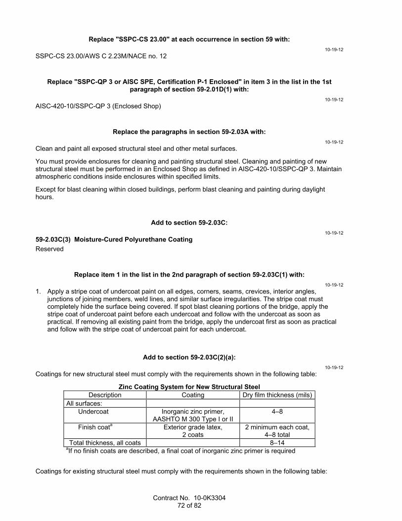
Contract No. 10-0K3304 72 of 82
Replace "SSPC-CS 23.00" at each occurrence in section 59 with:
10-19-12
SSPC-CS 23.00/AWS C 2.23M/NACE no. 12
Replace "SSPC-QP 3 or AISC SPE, Certification P-1 Enclosed" in item 3 in the list in the 1st paragraph of section 59-2.01D(1) with:
10-19-12
AISC-420-10/SSPC-QP 3 (Enclosed Shop)
Replace the paragraphs in section 59-2.03A with:
10-19-12
Clean and paint all exposed structural steel and other metal surfaces.
You must provide enclosures for cleaning and painting structural steel. Cleaning and painting of new structural steel must be performed in an Enclosed Shop as defined in AISC-420-10/SSPC-QP 3. Maintain atmospheric conditions inside enclosures within specified limits.
Except for blast cleaning within closed buildings, perform blast cleaning and painting during daylight hours.
Add to section 59-2.03C:
10-19-12
59-2.03C(3) Moisture-Cured Polyurethane Coating
Reserved
Replace item 1 in the list in the 2nd paragraph of section 59-2.03C(1) with:
10-19-12
1. Apply a stripe coat of undercoat paint on all edges, corners, seams, crevices, interior angles, junctions of joining members, weld lines, and similar surface irregularities. The stripe coat must completely hide the surface being covered. If spot blast cleaning portions of the bridge, apply the stripe coat of undercoat paint before each undercoat and follow with the undercoat as soon as practical. If removing all existing paint from the bridge, apply the undercoat first as soon as practical and follow with the stripe coat of undercoat paint for each undercoat.
Add to section 59-2.03C(2)(a):
10-19-12
Coatings for new structural steel must comply with the requirements shown in the following table:
Zinc Coating System for New Structural Steel Description Coating Dry film thickness (mils)
All surfaces: Undercoat Inorganic zinc primer,
AASHTO M 300 Type I or II 4–8
Finish coata Exterior grade latex, 2 coats
2 minimum each coat, 4–8 total
Total thickness, all coats 8–14 aIf no finish coats are described, a final coat of inorganic zinc primer is required
Coatings for existing structural steel must comply with the requirements shown in the following table:
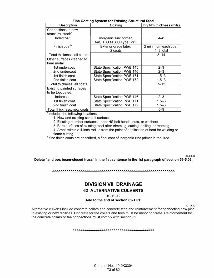
Contract No. 10-0K3304 73 of 82
Zinc Coating System for Existing Structural Steel Description Coating Dry film thickness (mils)
Connections to new structural steel:a
Undercoat Inorganic zinc primer, AASHTO M 300 Type I or II
4–8
Finish coatb Exterior grade latex, 2 coats
2 minimum each coat, 4–8 total
Total thickness, all coats 8–14 Other surfaces cleaned to bare metal:
1st undercoat 2nd undercoat
State Specification PWB 145 State Specification PWB 146
2–3 2–3
1st finish coat 2nd finish coat
State Specification PWB 171 State Specification PWB 172
1.5–3 1.5–3
Total thickness, all coats 7–12 Existing painted surfaces to be topcoated:
Undercoat State Specification PWB 146 2–3 1st finish coat 2nd finish coat
State Specification PWB 171 State Specification PWB 172
1.5–3 1.5–3
Total thickness, new coats 5–9 aIncludes the following locations:
1. New and existing contact surfaces 2. Existing member surfaces under HS bolt heads, nuts, or washers 3. Bare surfaces of existing steel after trimming, cutting, drilling, or reaming 4. Areas within a 4-inch radius from the point of application of heat for welding or flame cutting
bIf no finish coats are described, a final coat of inorganic zinc primer is required
07-20-12
Delete "and box beam-closed truss" in the 1st sentence in the 1st paragraph of section 59-5.03.
^^^^^^^^^^^^^^^^^^^^^^^^^^^^^^^^^^^^^^^^^^^^^^^^^^^^^^^^^^^^
DIVISION VII DRAINAGE 62 ALTERNATIVE CULVERTS
10-19-12 Add to the end of section 62-1.01:
10-19-12
Alternative culverts include concrete collars and concrete tees and reinforcement for connecting new pipe to existing or new facilities. Concrete for the collars and tees must be minor concrete. Reinforcement for the concrete collars or tee connections must comply with section 52.
^^^^^^^^^^^^^^^^^^^^^^^^^^^^^^^^^^^^^^^^

Contract No. 10-0K3304 74 of 82
64 PLASTIC PIPE 10-19-12
Replace the 2nd paragraph of section 64-1.01A with:
10-19-12
Plastic pipe includes all necessary elbows, wyes, tees, other branches, fittings, coupling systems, concrete collars or tees, and reinforcement.
^^^^^^^^^^^^^^^^^^^^^^^^^^^^^^^^^^^^^^^^
65 CONCRETE PIPE 10-19-12
Replace the 2nd paragraph of section 65-1.01 with:
10-19-12
Concrete pipe includes all necessary elbows, wyes, tees, other branches, concrete collars or tees, and reinforcement.
^^^^^^^^^^^^^^^^^^^^^^^^^^^^^^^^^^^^^^^^
70 MISCELLANEOUS DRAINAGE FACILITIES 01-20-12
Replace section 70-5.02A(2) with:
01-20-12
70-5.02A(2) Plastic Flared End Sections
Plastic flared end sections must comply with ASTM D 3350.
^^^^^^^^^^^^^^^^^^^^^^^^^^^^^^^^^^^^^^^^^^^^^^^^^^^^^^^^^^^^
DIVISION VIII MISCELLANEOUS CONSTRUCTION 72 SLOPE PROTECTION
01-20-12 Replace the row under "Class" in the table in the 1st paragraph of section 72-3.02B with:
01-20-12
1/2 T 1/4 T Light Facing Cobble
Replace the row under "Rock class" in the table in the 2nd paragraph of section 72-3.03E with:
01-20-12
1/2 T 1/4 T Light Facing Cobble
^^^^^^^^^^^^^^^^^^^^^^^^^^^^^^^^^^^^^^^^

Contract No. 10-0K3304 75 of 82
74 PUMPING EQUIPMENT AND CONTROLS 01-20-12
Replace the 1st sentence of the 1st paragraph in section 74-2.01D(2) with:
01-20-12
Drainage pumps must be factory certified under ANSI/HI 14.6.
^^^^^^^^^^^^^^^^^^^^^^^^^^^^^^^^^^^^^^^^
75 MISCELLANEOUS METAL 10-19-12
Replace "SSPC-QP 3" in the 3rd paragraph of section 75-1.03E(4) with:
10-19-12
AISC-420-10/SSPC-QP3
^^^^^^^^^^^^^^^^^^^^^^^^^^^^^^^^^^^^^^^^
Replace section 78 with:
07-20-12
78 INCIDENTAL CONSTRUCTION 07-20-12
78-1 GENERAL
Section 78 includes specifications for incidental bid items that are not closely associated with other sections.
78-2–78-50 RESERVED
^^^^^^^^^^^^^^^^^^^^^^^^^^^^^^^^^^^^^^^^
80 FENCES 10-19-12
Add to section 80-2.02D:
10-19-12
Vertical stays must:
1. Comply with ASTM A641 2. Be 12-1/2 gage 3. Have a Class 3 zinc coating
Replace item 1 in the list in section 80-2.02E with:
10-19-12
Comply with ASTM A 116, Type Z, Grade 60, Class 1
Add after "galvanized wire" in the 1st paragraph of section 80-2.02F:
10-19-12
complying with ASTM A 641

Contract No. 10-0K3304 76 of 82
Replace the 3rd and 4th paragraphs of section 80-2.02F with:
10-19-12
Each staple used to fasten barbed wire and wire mesh fabric to wood posts must:
1. Comply with ASTM F 1667 2. Be at least 1-3/4 inches long 3. Be manufactured from 9-gage galvanized wire Wire ties used to fasten barbed wire and wire mesh to metal posts must be at least 11-gage galvanized wire complying with ASTM F 626. Clips and hog rings used for metal posts must be at least 9-gage galvanized wire complying with ASTM F 626.
Replace the 8th through 14th paragraphs of section 80-2.03 with:
10-19-12
Attach the wire mesh and barbed wire to each post.
Securely fasten tension wires to wood posts. Make a single or double loop around each post at each attachment point and staple the wire to the post. Use wire ties, hog rings, or wire clips to fasten the wires to the metal posts.
Connect each wood brace to its adjacent post with a 3/8 by 4-inch steel dowel. Twist the tension wires until the installation is rigid.
Stretch barbed wire and wire mesh fabric and fasten to each wood or steel end, corner, or gate post. Apply tension according to the manufacturer’s instructions using a mechanical stretcher or other device designed for such use. If no tension is specified by the manufacturer, use 250 pounds for the required tension. Evenly distribute the pull over the longitudinal wires in the wire mesh such that no more than 50 percent of the original depth of the tension curves is removed. Do not use a motorized vehicle, truck, or tractor to stretch the wire.
Attach barbed wire and wire mesh fabric to the private-property side of posts. On curved alignments, place the wire mesh and barbed wire on the face of the post against which the normal pull of the wire mesh and wire will be exerted. Terminate the wire mesh and barbed wire at each end, corner, pull, and gate post in the new fence line. Attach wire mesh and barbed wire to each wood or steel end, corner, pull, or gate post by wrapping each horizontal strand around the post and tying it back on itself with at least 4 tightly-wound wraps.
At line posts, fasten the wire mesh to the post at the top and bottom and at intermediate points not exceeding 10 inches apart. Fasten each line of barbed wire to each line post. Use wire ties or clips to fasten the wires to metal posts under the post manufacturer’s instructions. Drive staples crosswise with the grain of the wood and pointed slightly downward. Drive staples just short of actual contact with the wires to allow free longitudinal movement of those wires and to prevent damage to the wire’s protective coating. Secure all wires to posts to maintain horizontal alignment.
Splices in barbed wire and wire mesh are allowed provided there are no more than 2 splices per 50 feet of fence. Use commercially-available galvanized mechanical wire splices or a wire splice created by tying off wire. Install mechanical wire splices with a tool designed for that purpose under the manufacturer's instructions. Tie off the wire as follows:
1. Carry the ends of each wire 3 inches past the tied-off knot location and wrap around the wire for at least 6 turns in opposite directions.
2. Remove the splice tool and close the space by pulling the end of the wires together. 3. Cut the unused ends of the wire close and neat.
Add to "≤ 6" in the table in the 4th paragraph of section 80-3.02B:
10-19-12
feet

Contract No. 10-0K3304 77 of 82
^^^^^^^^^^^^^^^^^^^^^^^^^^^^^^^^^^^^^^^^^^^^^^^^^^^^^^^^^^^^
DIVISION IX TRAFFIC CONTROL FACILITIES 83 RAILINGS AND BARRIERS
10-19-12 Replace "80-2.02" in the 2nd paragraph of section 83-1.02E with:
10-19-12
80-3.02B
Add to section 83-2.02:
10-19-12
83-2.02H–83-2.02M Reserved
Add to section 83-2.02D(1):
10-21-11
For a concrete barrier transition:
1. Remove portions of the existing concrete barrier where shown under section 15-3 2. Roughen the contact surface of the existing concrete barrier 3. Drill and bond dowels into the existing concrete barrier under section 51-1
^^^^^^^^^^^^^^^^^^^^^^^^^^^^^^^^^^^^^^^^
84 TRAFFIC STRIPES AND PAVEMENT MARKINGS 01-20-12
Replace the 1st paragraph in section 84-2.04 with:
01-20-12
A double extruded thermoplastic traffic stripe consisting of two 4-inch wide yellow stripes is measured as 2 traffic stripes.
A double sprayable thermoplastic traffic stripe consisting of two 4-inch wide yellow stripes is measured as 1 traffic stripe.
Add to section 84:
01-20-12
84-6 THERMOPLASTIC TRAFFIC STRIPES AND PAVEMENT MARKINGS WITH ENHANCED WET NIGHT VISIBILITY
Reserved
84-7–84-10 RESERVED
^^^^^^^^^^^^^^^^^^^^^^^^^^^^^^^^^^^^^^^^

Contract No. 10-0K3304 78 of 82
86 ELECTRICAL SYSTEMS 10-19-12
Replace section 86-2.06 with:
01-20-12
86-2.06 PULL BOXES
86-2.06A General
86-2.06A(1) Cover Marking
Marking must be clearly defined, uniform in depth, and parallel to either the long or short sides of the cover.
Marking letters must be 1 to 3 inches high.
Before galvanizing steel or cast iron cover, apply marking by one of the following methods:
1. Use cast iron strip at least 1/4 inch thick with letters raised a minimum of 1/16 inch. Fasten strip to cover with 1/4-inch flathead stainless steel machine bolts and nuts. Peen bolts after tightening.
2. Use sheet steel strip at least 0.027 inch thick with letters raised a minimum of 1/16 inch. Fasten strip to cover by spot welding, tack welding, or brazing, with 1/4-inch stainless steel rivets or 1/4-inch roundhead stainless steel machine bolts and nuts. Peen bolts after tightening.
3. Bead weld the letters on cover such that the letters are raised a minimum of 3/32 inch. 86-2.06A(2) Installation and Use
Space pull boxes no more than 200 feet apart. You may install additional pull boxes to facilitate the work.
You may use a larger standard size pull box than that shown on the plans or specified.
A pull box in ground or sidewalk area must be installed as follows:
1. Embed bottom of the pull box in crushed rock. 2. Place a layer of roofing paper on the crushed rock. 3. Place grout over the layer of roofing paper. Grout must be 0.50 to 1 inch thick and sloped toward the
drain hole. 4. Make a 1-inch drain hole in the center of the pull box through the grout and roofing paper. 5. Place grout between the pull box and the pull box extension, and around conduits. The top of the pull box must be flush with the surrounding grade or the top of an adjacent curb, except in unpaved areas where the pull box is not immediately adjacent to and protected by a concrete foundation, pole, or other protective construction. Place the pull box 1-1/4 inches above the surrounding grade. Where practical, place a pull box shown in the vicinity of curbs or adjacent to a standard on the side of the foundation facing away from traffic. If a pull box is installed in a sidewalk area, adjust the depth of the pull box so that the top of the pull box is flush with the sidewalk.
Reconstruct the sump of an existing pull box if disturbed by your activities. Remove old grout and replace with new if the sump was grouted.
86-2.06B Non-Traffic-Rated Pull Boxes
Reserved
86-2.06C Traffic Pull Boxes
Traffic pull box and cover must comply with ASTM C857, "Standard Practice for Minimum Structural Design Loading for Underground Precast Concrete Utility Structures," for HS20-44 loading. You must be able to place the load anywhere on the box and cover for 1 minute without causing cracks or permanent deformations.
Frame must be anchored to the box with 1/4 by 2-1/4 inch concrete anchors. Four concrete anchors must be included for No. 3-1/2(T) pull box; one placed in each corner. Six concrete anchors must be included for No. 5(T) and No. 6(T) pull boxes; one placed in each corner and one near the middle of each of the longer sides.
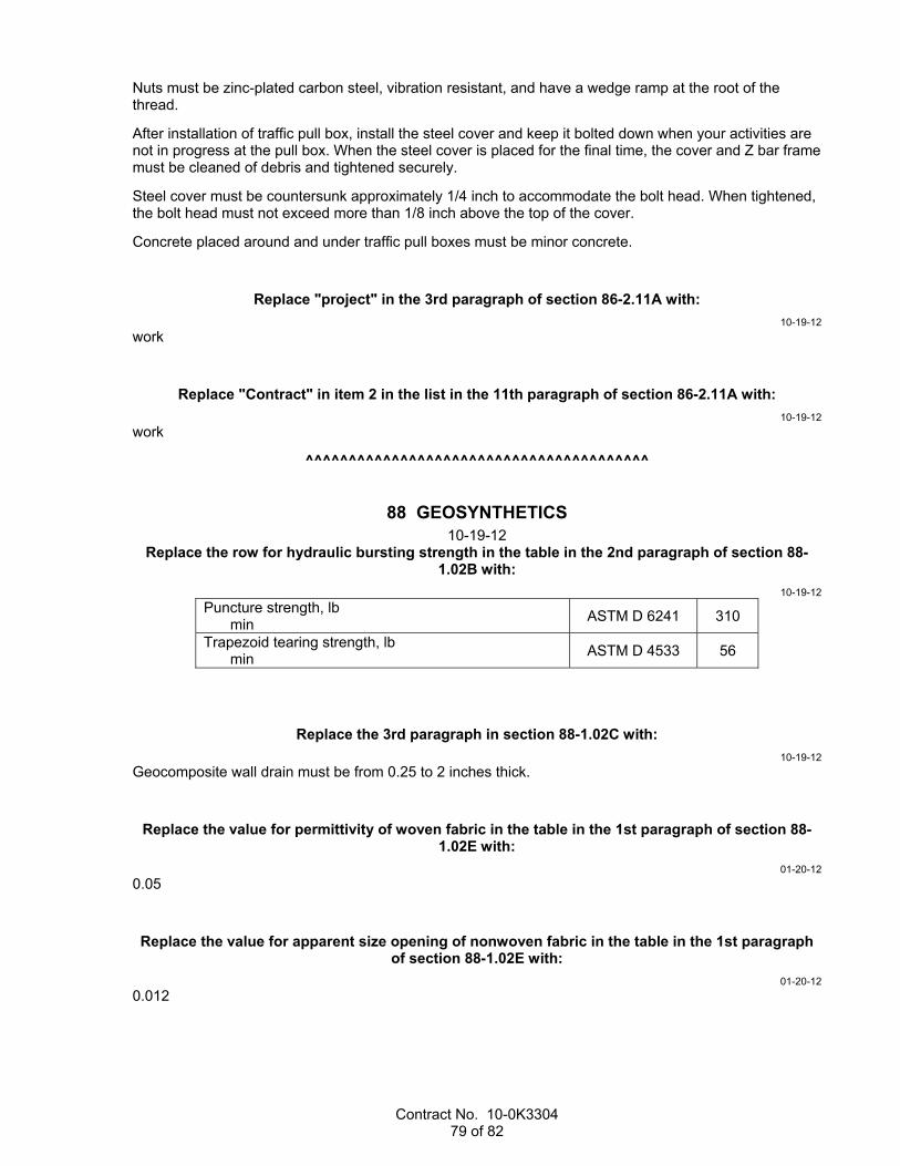
Contract No. 10-0K3304 79 of 82
Nuts must be zinc-plated carbon steel, vibration resistant, and have a wedge ramp at the root of the thread.
After installation of traffic pull box, install the steel cover and keep it bolted down when your activities are not in progress at the pull box. When the steel cover is placed for the final time, the cover and Z bar frame must be cleaned of debris and tightened securely.
Steel cover must be countersunk approximately 1/4 inch to accommodate the bolt head. When tightened, the bolt head must not exceed more than 1/8 inch above the top of the cover.
Concrete placed around and under traffic pull boxes must be minor concrete.
Replace "project" in the 3rd paragraph of section 86-2.11A with:
10-19-12
work
Replace "Contract" in item 2 in the list in the 11th paragraph of section 86-2.11A with:
10-19-12
work
^^^^^^^^^^^^^^^^^^^^^^^^^^^^^^^^^^^^^^^^
88 GEOSYNTHETICS 10-19-12
Replace the row for hydraulic bursting strength in the table in the 2nd paragraph of section 88-1.02B with:
10-19-12
Puncture strength, lb min
ASTM D 6241 310
Trapezoid tearing strength, lb min
ASTM D 4533 56
Replace the 3rd paragraph in section 88-1.02C with:
10-19-12
Geocomposite wall drain must be from 0.25 to 2 inches thick.
Replace the value for permittivity of woven fabric in the table in the 1st paragraph of section 88-1.02E with:
01-20-12
0.05
Replace the value for apparent size opening of nonwoven fabric in the table in the 1st paragraph of section 88-1.02E with:
01-20-12
0.012
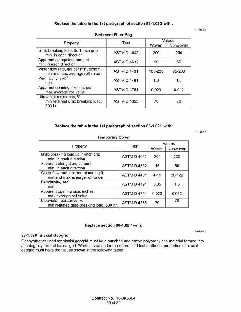
Contract No. 10-0K3304 80 of 82
Replace the table in the 1st paragraph of section 88-1.02G with:
01-20-12
Sediment Filter Bag
Property Test Values
Woven Nonwoven Grab breaking load, lb, 1-inch grip
min, in each direction ASTM D 4632 200 250
Apparent elongation, percent min, in each direction
ASTM D 4632 10 50
Water flow rate, gal per minute/sq ft min and max average roll value
ASTM D 4491 100-200 75-200
Permittivity, sec-1 min
ASTM D 4491 1.0 1.0
Apparent opening size, inches max average roll value
ASTM D 4751 0.023 0.012
Ultraviolet resistance, % min retained grab breaking load, 500 hr.
ASTM D 4355 70 70
Replace the table in the 1st paragraph of section 88-1.02H with:
01-20-12
Temporary Cover
Property Test Values
Woven Nonwoven Grab breaking load, lb, 1-inch grip
min, in each direction ASTM D 4632 200 200
Apparent elongation, percent min, in each direction
ASTM D 4632 15 50
Water flow rate, gal per minute/sq ft min and max average roll value
ASTM D 4491 4-10 80-120
Permittivity, sec-1 min
ASTM D 4491 0.05 1.0
Apparent opening size, inches max average roll value
ASTM D 4751 0.023 0.012
Ultraviolet resistance, % min retained grab breaking load, 500 hr.
ASTM D 4355 70 70
Replace section 88-1.02P with:
10-19-12
88-1.02P Biaxial Geogrid
Geosynthetics used for biaxial geogrid must be a punched and drawn polypropylene material formed into an integrally formed biaxial grid. When tested under the referenced test methods, properties of biaxial geogrid must have the values shown in the following table:

Contract No. 10-0K3304 81 of 82
Biaxial Geogrid
Property Test Value Aperture size, incha
min and max Calipered 0.8-1.3 x 1.0-1.6
Rib thickness, inch min
Calipered 0.04
Junction thickness, inch min
Calipered 0.150
Tensile strength, 2% strain, lb/fta min
ASTM D 6637 4.10 x 620
Tensile strength at ultimate, lb/fta
min ASTM D 6637 1,310 x 1,970
Ultraviolet resistance, percent min retained tensile strength, 500 hours
ASTM D 4355 100
Junction strength, lb/fta
min ASTM D 7737 1,220 x 1,830
Overall flexural rigidity, mg-cm min
ASTM D 7748 750,000
Torsional rigidity at 20 cm-kg, mm-kg/degb min
GRI:GG9 0.65 aMachine direction x cross direction bGeosynthetic Research Institute, Test Method GG9, Torsional Behavior of Bidirectional Geogrids When Subjected to In-Plane Rotation
^^^^^^^^^^^^^^^^^^^^^^^^^^^^^^^^^^^^^^^^^^^^^^^^^^^^^^^^^^^^
DIVISION X MATERIALS 90 CONCRETE
08-05-11 Replace the 3rd paragraph of section 90-1.01C(7) with:
08-05-11
Submit weighmaster certificates in printed form or, if authorized, in electronic media. Present electronic media in a tab-delimited format on a CD or DVD. Captured data for the ingredients represented by each batch must be line feed carriage return and one line separate record with sufficient fields for the specified data.
Replace the 3rd paragraph of section 90-3.01C(5) with:
08-05-11
Production data must be input by hand into a pre-printed form or captured and printed by the proportioning device. Present electronic media containing recorded production data in a tab-delimited format on a CD or DVD. Each capture of production data must be followed by a line feed carriage return with sufficient fields for the specified data.
^^^^^^^^^^^^^^^^^^^^^^^^^^^^^^^^^^^^^^^^

Contract No. 10-0K3304 82 of 82
91 PAINT 10-19-12
Add to section 91-2:
10-19-12
91-2.03 MOISTURE-CURED POLYURETHANE COATING
Reserved
Replace "saint" in the 1st paragraph of section 91-4.05 with:
10-19-12
paint
^^^^^^^^^^^^^^^^^^^^^^^^^^^^^^^^^^^^^^^^
92 ASPHALTS 01-20-12
Replace the row for dynamic shear for original binder in the table in the 1st paragraph of section 92-1.02B with:
01-20-12
Dynamic shear, Test temperature at 10 rad/s, °C min G*/sin(delta), kPa max G*/sin(delta), kPa
T 315 58 1.00 2.00
64 1.00 2.00
64 1.00 2.00
64 1.00 2.00
70 1.00 2.00