advanced onsite waste water systems technologies
TRANSCRIPT


ADVANCED ONSITEWASTEWATER SYSTEMS
TECHNOLOGIES

This page intentionally left blank

A CRC title, part of the Taylor & Francis imprint, a member of theTaylor & Francis Group, the academic division of T&F Informa plc.
Boca Raton London New York
ADVANCED ONSITEWASTEWATER SYSTEMS
TECHNOLOGIES
Anish R. Jantrania
Mark A. Gross
Virginia Department of HealthRichmond, Virginia, U.S.A.
University of ArkansasFayetteville, Arkansas, U.S.A.

Published in 2006 byCRC PressTaylor & Francis Group 6000 Broken Sound Parkway NW, Suite 300Boca Raton, FL 33487-2742
© 2006 by Taylor & Francis Group, LLCCRC Press is an imprint of Taylor & Francis Group
No claim to original U.S. Government worksPrinted in the United States of America on acid-free paper10 9 8 7 6 5 4 3 2 1
International Standard Book Number-10: 0-8493-3029-7 (Hardcover) International Standard Book Number-13: 978-0-8493-3029-2 (Hardcover) Library of Congress Card Number 2005050884
This book contains information obtained from authentic and highly regarded sources. Reprinted material isquoted with permission, and sources are indicated. A wide variety of references are listed. Reasonable effortshave been made to publish reliable data and information, but the author and the publisher cannot assumeresponsibility for the validity of all materials or for the consequences of their use.
No part of this book may be reprinted, reproduced, transmitted, or utilized in any form by any electronic,mechanical, or other means, now known or hereafter invented, including photocopying, microfilming, andrecording, or in any information storage or retrieval system, without written permission from the publishers.
For permission to photocopy or use material electronically from this work, please access www.copyright.com(http://www.copyright.com/) or contact the Copyright Clearance Center, Inc. (CCC) 222 Rosewood Drive,Danvers, MA 01923, 978-750-8400. CCC is a not-for-profit organization that provides licenses and registrationfor a variety of users. For organizations that have been granted a photocopy license by the CCC, a separatesystem of payment has been arranged.
Trademark Notice: Product or corporate names may be trademarks or registered trademarks, and are used onlyfor identification and explanation without intent to infringe.
Library of Congress Cataloging-in-Publication Data
Jantrania, Anish (Anish R.)Advanced onsite wastewater systems technologies / Anish Jantrania and Mark Alan Gross.
p. cm.Includes bibliographical references and index.ISBN 0-8493-3029-71. Sewage disposal, Rural. I. Gross, Mark. II. Title.
TD929.J36 2005628.3--dc22 2005050884
Visit the Taylor & Francis Web site at http://www.taylorandfrancis.com
and the CRC Press Web site at http://www.crcpress.com
Taylor & Francis Group is the Academic Division of Informa plc.
3029_Discl.fm Page 1 Tuesday, November 22, 2005 4:08 PM

Foreword
Issues associated with management of human waste have plagued societiesthroughout history. Ancient texts refer to a variety of methods to mangehuman waste and in the generations since societies began to develop wehave developed a better understanding of the public health, environmentalquality and economic impacts of waste management programs and pro-cesses. As communities developed into cities, the need to treat and managewaste became critical and when water carrying plumbing developed, theneed to find effective solutions to the issues associated with waste manage-ment was amplified tremendously.
Professions developed to address these issues. Here in the United States,the Public Health Service evolved to address issues of waste management.With passage of the Clean Water Act in the late 1960’s, environmental healthpractice and wastewater engineering practice diverged. Since the CleanWater Act, tremendous federal resource has been allocated for proliferationof the large collection and treatment systems and there has been a perceptionthat the onsite and decentralized efforts have waned.
In truth, much of the support for the onsite and decentralized effort hascome from state and local government. The research and technology devel-opment associated with the onsite and decentralized system demonstratesthat these are viable options for all areas of the country. Applications of theseappropriate technologies and associated management programs are evidentin urban, sub-urban, and rural areas. The USEPA and state agencies recog-nize the value of appropriate wastewater solutions.
This text addresses planning, design operations and maintenance issuesassociated with those technologies required as part of a comprehensive pre-application treatment. It discusses the variety of dispersal options availableto distribute treated or reclaimed water into receiving environments anddescribes the opportunities available for recycling and reuse. Finally, thistext discusses the importance of a comprehensive planning and managementapproach to dealing with wastewater management issues.
Drs. Anish Jantrania and Mark Gross have many years of valuableexperience and they have synthesized and assembled that experience toprovide this tremendously valuable reference for all environmental healthand wastewater engineering practitioners. This text provides a well devel-oped and comprehensive assessment of technology and management
3029_book.fm Page 5 Wednesday, November 23, 2005 10:30 AM

solutions available to address a variety of waste management challenges.This text is an indispensable reference for all professionals involved in theplanning, design, installation, operation, maintenance and management ofwastewater systems.
Robert A. Rubin, Ed.D.Professor Emeritus and Senior Environmental SpecialistNorth Carolina State University and McKim & CreedRaleigh, North Carolina, [email protected]
3029_book.fm Page 6 Wednesday, November 23, 2005 10:30 AM

Preface
Onsite treatment of wastewater and onsite dispersal of treated wastewateris not a new concept. Throughout the history of civilization in this countryand other places in the world, onsite wastewater systems have been andwill be an integral part of the overall wastewater management infrastruc-ture. Onsite wastewater systems are here to stay and the U.S. Environmen-tal Protection Agency (EPA) views adequately managed onsite systems asa cost-effective and long-term option for meeting public health and waterquality goals, particularly in less densely populated areas. For one out ofevery four homes in the U.S. wastewater is treated onsite, typically usinga septic tank and a drain field system. A septic system was, and with somemodifications still is, the most common method for onsite wastewatertreatment. However, just like any other field, significant advances havebeen achieved in onsite wastewater treatment and effluent dispersal tech-nologies. A septic tank is now viewed only as a level one treatment system,while a variety of technologies such as packed bed media filters and flow-through or sequencing batch reactor treatment system are now consideredas level two, three, or even level four treatment systems. These advancedsystems can treat wastewater onsite from a single home or a cluster ofhomes, to effluent standards similar to those achieved by large centralizedtreatment plants. Highly treated wastewater can now be dispersed onsiteusing a conventional drain field or any one of the advanced technologiessuch as drip, spray, filter bed, evapo-transpiration bed, and greenhousesystem, on land that is typically rejected for use of septic systems, i.e., onland that doesn’t perc.
This book has three goals: introducing readers to advanced onsitewastewater systems technologies, suggesting regulatory and managementframeworks for effective use of such technologies, and proposing vocabu-lary to better understand the benefits of such technologies. The advancedsystems can meet demands for onsite wastewater management on twomain fronts—new growth that is occurring in areas not served by central-ized collection and treatment plants (sewer systems), and existing homesand businesses with failing or inadequate septic systems. The advancedsystems’ operations can be managed using monitoring devices that sendsignals to a central location, allowing a trained operator to ensure treatmentperformance of multiple systems by offering scheduled and emergency
3029_book.fm Page 7 Wednesday, November 23, 2005 10:30 AM

services. Centralized management of onsite systems is now a reality anda necessity for all onsite systems. The five management models proposedby the U.S. Environmental Protection Agency (EPA)
offer a good frame-work for initiating a global movement to bring all onsite wastewater sys-tems into some form of recognizable management program so that theirimpact on public health and water quality can be measured and improved.Advanced onsite wastewater systems put more emphasis on treatmentbefore discharge compared to conventional septic systems, thus requiringa higher degree of operational monitoring and ensuring measurable per-formance on a long-term basis. The onsite stakeholders are home andbusiness owners, land developers, builders, planners, regulators, educa-tors, trainers, consultants, designers, engineers, manufacturers, and serviceproviders. They are intimately familiar with the use of septic systems andsoil and site issues related to the perc test. To them, this book offers a newvocabulary of terms such as pollution scale, treatment scale, wastewatertreatability, treatment levels, overall treatment levels, treatment before andafter discharge, soil and site credits, performance standards, and perfor-mance matrix. The new vocabulary will improve communication amongthe onsite stakeholders for discussing advanced onsite wastewater systemstechnologies.
Advanced onsite systems should be viewed not just as an alternative toseptic systems or centralized systems, but as an integral part of any waste-water infrastructure. Information in this book will complement the educa-tional and training efforts undertaken by national organizations such asNOWRA, NEHA, NAWT, NSF, ASAE, WEF, NSFC, and regional/state asso-ciations, representing interests of onsite stakeholders. Improved knowledgeand understanding of this subject matter will allow millions of home andbusiness owners to have better access to the advanced onsite wastewatersystems to meet their current and future wastewater needs. Education andtraining of wastewater professionals must parallel regulatory reform in orderto adequately justify the newly developed professionalism and responsibil-ities undertaken by the certified and licensed professionals. Regulatory pro-grams that were designed and developed for using conventional septic sys-tems are no longer valid as the technology, management, and overallunderstanding of advanced onsite systems develop. Thus, there is a needfor thorough evaluation and restructuring of state and local regulatory pro-grams for onsite systems. This book offers suggestions on management andregulatory frameworks necessary for allowing the new generation of profes-sionals to offer their services using advanced onsite wastewater systems thatare currently available in the market.
Onsite systems must not be used as the tool for controlling growth inareas that are not served by centralized collection and treatment systems.Advanced onsite wastewater systems, just like technologies such as satellitetelevision or wireless phone, neither require centralized networks of hard-ware nor special type of soil or site conditions for adequate onsite wastewatertreatment and effluent dispersal. With the right regulatory attitude towards
3029_book.fm Page 8 Wednesday, November 23, 2005 10:30 AM

public health and water quality protection goals, and with the right attitudefrom the products and service providers, it is now possible for adequatelytrained and appropriately licensed onsite wastewater professionals to offeronsite wastewater services to home and business owners on a permanentbasis.
We would like to thank our friends, colleagues, and mentors in thewastewater technologies field who have contributed to moving away fromstatus quo. We are thankful to our editor and publisher for the help andsupport they have provided. We would like to express our heartfelt gratitudeto our families for their patience, encouragement, love, and support duringthe entire process of getting this book ready for publication.
Views expressed in this book are our own and they do not reflect viewsof our past, current, and future employers.
Anish R. Jantrainia, Ph.D., P.E.Technical Services EngineerVirginia Department of HealthRichmond, Virginia, [email protected]
Mark A. Gross, Ph.D., P.E.ProfessorUniversity of ArkansasFayetteville, Arkansas, [email protected]
3029_book.fm Page 9 Wednesday, November 23, 2005 10:30 AM

This page intentionally left blank

Dedication
We dedicate this book to our family members, friends, and peers who constantly provided much needed support and the push for starting
this project and getting it to completion.
3029_book.fm Page 11 Wednesday, November 23, 2005 10:30 AM

This page intentionally left blank

About the Authors
Anish R. JantraniaAnish R. Jantrania is a Technical Services Engineer at the Virginia Depart-ment of Health in the Onsite Sewage and Water Program. Prior to joiningthe state health department in 1996, he worked for two years as an Engi-neering Consultant for the city of Gloucester, Massachusetts on the firstnational onsite demonstration projects funded by the U.S. EPA. Before thathe worked as a Technical Program Coordinator at the National Small FlowsClearinghouse for four years. He received his B.E. in Agricultural Engi-neering from the College of Technology and Agricultural Engineering,Udaipur, India in 1982, M.S. in Agricultural Engineering from the OhioState University in 1985 and Ph.D. in Agricultural Engineering with spe-cialization in Environmental Systems Engineering from Clemson Univer-sity in 1989. He has also received M.B.A. from West Virginia University in1994 and is a registered professional engineer in Virginia, Massachusetts,and West Virginia. He has served on the board of directors for the NationalOnsite Wastewater Recycling Association (NOWRA) and has served on thetechnical review committee for revising the U.S. EPA Onsite Design Manualand is currently serving on the NOWRA Model Performance Code primarycommittee and evaluation committee.
Mark A. GrossMark Gross is a professor of Civil Engineering at the University of Arkansasin Fayetteville, Arkansas. He has a B.S. in Civil Engineering, M.S. in CivilEngineering, and a Ph.D. in Engineering. Dr. Gross has 20 years of experiencein the decentralized wastewater field both as a teacher and as a designer.He has authored or co-authored over 75 articles in the field. His research isin the area of decentralized wastewater, currently working on phosphorusremoval in soil-based systems. He maintains an active consulting practicein addition to his university duties, and is a registered professional engineerin Arkansas, Tennessee, Mississippi, Missouri, and Virginia.
3029_book.fm Page 13 Wednesday, November 23, 2005 10:30 AM

This page intentionally left blank

Contents
Chapter one Onsite wastewater management: an overviewIntroduction ............................................................................................................1Septic systems versus advanced onsite systems versus centralized
treatment ........................................................................................................5Managed advanced onsite treatment .................................................................6Wastewater treatment levels and receiving environment ..............................7Septic systems cannot do it alone .......................................................................9Onsite treatment to levels greater than septic tanks .....................................12Use of soil for the majority of the treatment is not required....................... 13Assimilation: subsurface or surface dispersal of effluent .............................13Responsible management and regulations .....................................................14Onsite technology is ready for the 21st century ............................................17Advanced onsite treatment systems ................................................................18
ATUs ............................................................................................................19Media filters ................................................................................................. 19Natural systems ..........................................................................................20Waterless systems .......................................................................................21Disinfection systems ...................................................................................22
Onsite effluent dispersal systems .....................................................................22Remote monitoring system ................................................................................24Regulatory framework ........................................................................................25
Chapter two Decentralized wastewater solutions Introduction ..........................................................................................................31The term decentralized .......................................................................................32Centralized versus decentralized solutions ....................................................33
Components of wastewater systems .......................................................34Categorizing decentralized and centralized systems ...........................34The science of wastewater ........................................................................35Pollution scale .............................................................................................35
Wastewater treatment basics .............................................................................48Treatability ...................................................................................................48Temperature and FOG ...............................................................................59
Determining wastewater characteristics ..........................................................61A simple look at wastewater treatment ..........................................................62
3029_book.fm Page 15 Wednesday, November 23, 2005 10:30 AM

Concept of overall treatment levels ..................................................................63Soil and site issues ..............................................................................................70
Chapter three Media filters Introduction ..........................................................................................................73Theory of attached-growth wastewater treatment systems .........................75Types of natural and synthetic media used for treating wastewater .........78
Sand and gravel filters ...............................................................................80Peat filters ....................................................................................................80Manufactured media filters .......................................................................81
Flow and load estimates .....................................................................................81Single-pass systems .............................................................................................82
Single-pass sand filter media ....................................................................84Loading rate and surface area ..................................................................85Single-pass peat filters ...............................................................................87
Methods and benefits of recirculation .............................................................87Recirculation ratio .......................................................................................89Recirculating sand filters ...........................................................................93Recirculating gravel filters ........................................................................93Recirculation tanks .....................................................................................93Recirculating sand filter media ................................................................94Filter drain ...................................................................................................95Loading rate and surface area ..................................................................95Distribution system design .......................................................................97Pumping systems for recirculating sand filters .....................................99Large recirculating sand filters and recovery techniques ....................99
Textile filters .......................................................................................................100Open cell foam filters ...............................................................................102
Controls ...............................................................................................................103Level sensors .............................................................................................105Determining timer settings .....................................................................105
Pump selection ...................................................................................................108Other fixed film processes ...............................................................................109System monitoring and maintenance ............................................................109
Monitoring tubes ......................................................................................109Remote monitoring ................................................................................... 110Monitoring routine ................................................................................... 110Monitoring User Inputs ........................................................................... 111Soil dispersal of media filter effluent .................................................... 112
Chapter four Aerobic treatment units Introduction ........................................................................................................ 115
Theory of biochemical wastewater treatment using aerobic treatment processes ........................................................................................ 116
Microbial metabolism .............................................................................. 117Fermentation and respiration ................................................................. 117
3029_book.fm Page 16 Wednesday, November 23, 2005 10:30 AM

Biosynthesis ............................................................................................... 119Endogenous Respiration .......................................................................... 119Environmental factors ..............................................................................120Temperature ...............................................................................................120Food-to-microorganism ratio ..................................................................120Acid concentration ...................................................................................121
Aerobic treatment unit operation ...................................................................121Process description ...................................................................................121
Typical ATU configurations .............................................................................122Extended aeration .....................................................................................122Suspended-growth bioreactors ...............................................................123Attached-growth bioreactors ..................................................................124Coupled contact aeration ........................................................................124
Rotating biological contactor .....................................................125Sequencing batch reactor systems or periodic processes ..................126
SBR process description ..............................................................126Nitrogen removal in SBRs ..........................................................127Typical applications of SBRs ......................................................128
Other Process Considerations .........................................................................128Oxygen transfer ........................................................................................128
ATU influent .......................................................................................................130Hydraulic and organic loading .......................................................................130Flow equalization ..............................................................................................131Nitrogen and phosphorus in wastewater .....................................................131Operational issues .............................................................................................132
Start up .......................................................................................................132Typical problems .......................................................................................132Biomass (sludge) wastage .......................................................................133
Performance certification ..................................................................................133Mechanical evaluation .............................................................................133Performance evaluation ...........................................................................134
References ...........................................................................................................135
Chapter five Effluent dispersal and recycling systems Introduction ........................................................................................................137Dispersal of advanced secondary effluent ....................................................138
Effluent dispersal technologies ...............................................................138Soil and site evaluation: then and now ................................................142
Assimilation: subsurface dispersal of effluent ..............................................153New concept for effluent dispersal system design ......................................155
Experimental design example ................................................................156Field Evaluation ........................................................................................158
Nitrogen reduction and the effluent dispersal system ...............................160Nitrogen model .........................................................................................161
Total maximum yearly load (TMYL) .............................................................163
3029_book.fm Page 17 Wednesday, November 23, 2005 10:30 AM

Chapter six Management framework for using advanced onsite wastewater systems technologies
Introduction ........................................................................................................167Centralized versus onsite wastewater systems’ management ..........168
EPA management models ................................................................................168Responsible Management Entity (RME) ...............................................169
Who can be an RME? ........................................................................................171Utility/RME system concept ...........................................................................172Value-added services ........................................................................................174Redefining the roles ..........................................................................................175Helping the onsite industry .............................................................................176Serving the people and the environment ......................................................176Long-term cost ...................................................................................................177Regulatory changes needed .............................................................................178Examples of utility programs ..........................................................................178
Chapter seven Regulatory framework for using advanced onsite wastewater systems technologies
Introduction ........................................................................................................181Regulatory framework for use of septic systems ........................................183Regulatory framework for use of advanced onsite systems ......................185
Solution driven system ............................................................................185Performance-based framework ..............................................................187
Building a foundation for performance-based regulations ........................190Onsite system classifications ...................................................................192
Performance monitoring requirements matrix .............................................193Approval process for advanced onsite technology .....................................197
Performance verification protocol ..........................................................198Approved process .....................................................................................205
Soil and site issues ............................................................................................215Soil loading rates and gross area ...........................................................216Separation and setback distances ..........................................................216Site conditions ...........................................................................................221
Building agreement ...........................................................................................222Philosophy .................................................................................................222Concept .......................................................................................................222Approach ....................................................................................................223
Chapter eight Planning with advanced onsite systems technologies Introduction ........................................................................................................227Integrating the use of advanced onsite systems in planning ....................228Onsite versus centralized wastewater systems ............................................229
Wastewater management at small scale ...............................................230Wastewater and the receiving environment .................................................232Operation and management infrastructure ..................................................235
3029_book.fm Page 18 Wednesday, November 23, 2005 10:30 AM

Chapter nine The future of advanced onsite systems technologies Introduction ........................................................................................................243Managed onsite systems ..................................................................................244Why treat beyond the septic tank? .................................................................246Fixing current problems and addressing future needs ...............................247Performance monitoring is now possible ......................................................249Regulating use of onsite systems online .......................................................250
Five steps to E-government for onsite systems ...................................252Step 1: Creating web sites and posting current information on
them .................................................................................252Step 2: Limited online interaction with users .........................253Step 3: Applying for a permit online .......................................254Step 4: Processing permit applications online ........................255Step-5: Issuing permits online ...................................................257
The future is bright ...........................................................................................258
Index .....................................................................................................................259
3029_book.fm Page 19 Wednesday, November 23, 2005 10:30 AM

This page intentionally left blank

1
chapter one
Onsite wastewater management: an overview
IntroductionAs the wastewater industry advances in the 21st century, the tools andprocesses used for onsite wastewater management must be evaluated. Suchan evaluation should include onsite wastewater treatment and treated waste-water dispersal or reuse technologies, regulatory frameworks, operation andmaintenance (management) frameworks, and community planning pro-cesses. This book presents information on advanced onsite wastewater tech-nologies and offers a framework on how to use these technologies to solveexisting onsite wastewater problems, such as failing or inadequate septicsystems, and to meet future demands for wastewater treatment in areas thatare not served by centralized collection and treatment systems. It also intro-duces concepts specific to regulatory and management framework that arenecessary to further advance the efficient use of onsite systems. As thepopulations grow in areas not served by centralized wastewater systems,the demand for managing wastewater onsite in an environmentally soundand cost-effective manner also will grow. This book is designed to fill theinformation gap that currently exists among different stakeholders, such ascustomers, product and service providers, and regulators of the onsite waste-water industry.
The concept of wastewater management started on a small scale, focus-ing mainly on disposal of human waste using systems such as privies.During the early part of the twentieth century, the focus shifted to treatmentof wastewater prior to disposal using large-scale, centralized collection andtreatment systems in densely populated areas, and millions of septic systemsin rural, typically less populated areas. Onsite wastewater managementprimarily focuses on adequate treatment of wastewater and dispersal oftreated waste water (effluent) at or near the place of generation. Toward theend of the 20th century, numerous advanced onsite wastewater systemstechnologies were developed and the technological advancements are
3029_book.fm Page 1 Wednesday, November 23, 2005 10:30 AM

2 Advanced onsite wastewater systems technologies
expected to continue in this century. With proper management, advancedonsite systems technologies are reliable and permanent alternatives to tra-ditional septic systems and centralized collection and treatment systems.
The 1990 census data indicate that septic tank treatment and drain fieldeffluent dispersal systems serve approximately 25% of the household unitsin the U.S. (the 2000 census did not collect this information). The number ofhousehold units that are not served by centralized collection and wastewatertreatment systems has actually increased from about 19.5 million, indicatedin the 1970 census data, to 25.8 million, indicated in the 1990 census data,an increase of about 6.3 million household units over the period of 20 years.
Table 1.1 contains the 1990 census data for the numbers of homes servedby onsite systems and those served by centralized systems for each state inthe union. Most, if not all, of these existing onsite systems are managed bytheir owners, who typically implement minimum or no maintenance of theirsystems and replace the systems when they fail. The U.S. EnvironmentalProtection Agency (EPA) reported to Congress that approximately 37% ofnew development of residential and/or commercial dwellings occur in areasthat are not served by centralized collection and treatment systems. At thisrate of increase, the Electric Power Research Institute (EPRI) projects thatthere will be 8.9 million new onsite systems in the U.S. by the year 2015.Their distribution by state is shown in Figure 1.1.
In Response to Congress On Use of Decentralized Wastewater Treatment Sys-tems (EPA, 1997), the U.S. EPA states that adequately managed decentralizedwastewater systems are a cost-effective and long-term option for meetingpublic health and water quality goals, particularly in less densely populatedareas. The wastewater industry will continue to move toward widespreaduse of advanced onsite wastewater systems with management (also calledmanaged decentralized systems) in this century and in the future.
Our goals for writing this book are twofold. First, we hope to familiarizereaders with the currently available advanced onsite wastewater systemstechnologies. Second, we hope to develop a standard vocabulary for profes-sionals who work with these technologies as well as for the customers whodepend on these technologies. This book, along with the supporting website www.advancedonsitesystems.com, is designed to act as an information cat-alog for advanced onsite wastewater technologies and offer communicationtools that will allow onsite wastewater professionals to communicate witheach other and with their clients in an effective manner so as to minimizeconfusion and misunderstanding related to the use of advanced onsite sys-tems on a permanent basis with management.
To the professionals offering such services as site evaluation, systemselection, sizing, and design, installation, and system operation, this bookserves as a resource of the technologies that they can use in their tool boxes,provides an objective method to assess the performance of such technologies,presents examples of real-world applications of advanced onsite systemstechnologies, and presents details on a management framework under whichthey can offer wastewater services using advanced onsite technologies in a
3029_book.fm Page 2 Wednesday, November 23, 2005 10:30 AM

Chapter one: Onsite wastewater management: an overview 3
Table 1.1 1990 Census Data on Wastewater Management Methods
Source: Onsite Wastewater Treatment Systems Manual, U.S. EPA February 2002 (EPA/625/R-00/008).
Public SewerSeptic Tank or cesspool Other Means TOTAL
76,455,211 24,670,877 1,137,590 102,263,678 Alabama 910,782 728,690 30,907 1,670,379 Alaska 144,905 59,886 27,817 232,608 Arizona 1,348,836 282,897 27,697 1,659,430 Arkansas 601,188 382,467 17,012 1,000,667 California 10,022,843 1,092,174 67,865 11,182,882 Colorado 1,283,186 183,817 10,346 1,477,349 Connecticut 935,541 378,382 6,927 1,320,850 Delaware 212,793 74,541 2,585 289,919 District of Columbia 276,481 575 1,433 278,489 Florida 4,499,793 1,559,113 41,356 6,100,262
Georgia 1,638,979 970,686 28,753 2,638,418 Hawaii 312,812 72,940 4,058 389,810 Idaho 264,618 142,879 5,830 413,327 Illinois 3,885,689 598,125 22,461 4,506,275 Indiana 1,525,810 703,032 17,204 2,246,046 Iowa 869,056 264,889 9,724 1,143,669 Kansas 847,767 187,398 8,947 1,044,112 Kentucky 849,491 600,182 57,172 1,506,845 Louisiana 1,246,678 442,758 26,805 1,716,241 Maine 266,344 301,373 19,328 587,045
Maryland 1,533,799 342,523 15,595 1,891,917 Massachusetts 1,803,176 659,120 10,415 2,472,711 Michigan 2,724,408 1,090,481 33,037 3,847,926 Minnesota 1,356,520 467,936 23,989 1,848,445 Mississippi 585,185 387,406 37,832 1,010,423 Missouri 1,617,996 532,844 48,289 2,199,129 Montana 218,372 135,371 7,412 361,155 Nebraska 534,692 117,460 8,469 660,621 Nevada 456,107 60,508 2,243 518,858 New Hampshire 250,060 246,692 7,152 503,904
New Jersey 2,703,489 357,890 13,931 3,075,310 New Mexico 452,934 161,068 18,056 632,058 New York 5,716,917 1,460,873 49,101 7,226,891 North Carolina 1,403,033 1,365,632 49,528 2,818,193 North Dakota 204,328 66,479 5,533 276,340 Ohio 3,392,785 940,943 38,217 4,371,945 Oklahoma 1,028,594 367,197 10,708 1,406,499 Oregon 835,545 349,122 8,900 1,193,567 Pennsylvania 3,670,338 1,210,054 57,748 4,938,140 Rhode Island 293,901 118,410 2,261 414,572
South Carolina 825,754 578,129 20,272 1,424,155 South Dakota 207,996 78,435 6,005 292,436 Tennessee 1,213,934 781,616 30,517 2,026,067 Texas 5,690,550 1,266,713 51,736 7,008,999Utah 528,864 65,403 4,121 598,388Vermont 115,201 149,125 6,888 271,214Virginia 1,740,787 707,409 48,138 2,496,334Washington 1,387,396 630,646 14,336 2,032,378West Virginia 427,930 318,697 34,668 781,295Wisconsin 1,440,024 580,836 34,914 2,055,774Wyoming 151,004 49,055 3,352 203,411
3029_book.fm Page 3 Wednesday, November 23, 2005 10:30 AM

4 Advanced onsite wastewater systems technologies
way similar to the services offered by centralized collection and treatmentsystems. To the regulators, this book presents details on a solution-drivenand performance-based regulatory framework that is necessary to regulateuse of advanced onsite systems as a true alternative to centralized collectionand treatment plants. To the community planners, this book offers guidanceon how to plan for future growth with such systems. Finally, to the devel-opers, builders, and property owners, this book gives answers to the age-oldquestion, “What do you do when the land does not perc and the sewer isnot coming?”
This book is organized as follows. The remainder of this chapter isdevoted to an overview of advanced onsite systems technologies and howthey compare to conventional onsite systems as well as centralized waste-water systems. Chapter 2 presents the concepts of decentralized wastewatersolutions and covers topics related to wastewater characteristics, wastewatertreatment basics, overall treatment levels (OTLs) for advanced onsite sys-tems, and locations in which advanced onsite systems can be used for man-aging wastewater. Chapters 3 and 4 present information on variousadvanced onsite wastewater treatment technologies that are currently avail-able for addressing onsite wastewater treatment needs. Chapter 5 presentsinformation on advanced onsite effluent dispersal technologies for dispers-ing high-quality effluent on sites that are typically considered unsuitable foruse of onsite systems. Chapters 6, 7, and 8 present information on the man-
Figure 1.1 Number of onsite systems (in thousands, approx) projections for 2015based on EPRI data.
Number of Onsite Systems (in thousands, approx.)Projections for 2015 Based on EPRI Data
441
110
375230
803
142435
413
112
4541,028
2,005
1,466
1,649
1,102
1,044
1,531
2,350
2,170
1,604
1,050
425
808
970
882
839
1419,
748
617
296
739
602
595
540
220
148
110
78308
123
388
306573
108132
281484
132
608
685
3029_book.fm Page 4 Wednesday, November 23, 2005 10:30 AM
Chapter one: Onsite wastewater management: an overview 5
agement, regulatory, and planning framework necessary to adopt use ofadvanced onsite systems technologies as alternatives to conventional septicsystems and centralized collection and treatment plants. Chapter 9 presentsour views on the future of advanced onsite systems technologies.
Septic systems versus advanced onsite systems versus centralized treatment
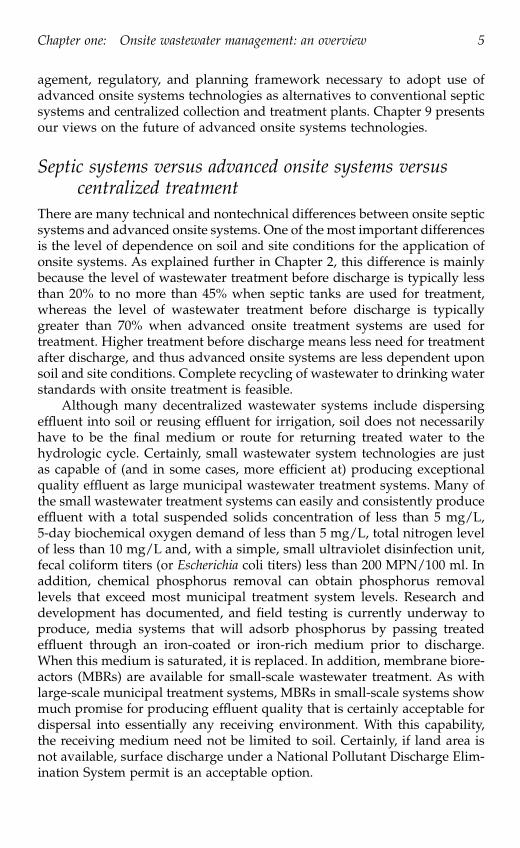
There are many technical and nontechnical differences between onsite septicsystems and advanced onsite systems. One of the most important differencesis the level of dependence on soil and site conditions for the application ofonsite systems. As explained further in Chapter 2, this difference is mainlybecause the level of wastewater treatment before discharge is typically lessthan 20% to no more than 45% when septic tanks are used for treatment,whereas the level of wastewater treatment before discharge is typicallygreater than 70% when advanced onsite treatment systems are used fortreatment. Higher treatment before discharge means less need for treatmentafter discharge, and thus advanced onsite systems are less dependent uponsoil and site conditions. Complete recycling of wastewater to drinking waterstandards with onsite treatment is feasible.
Although many decentralized wastewater systems include dispersingeffluent into soil or reusing effluent for irrigation, soil does not necessarilyhave to be the final medium or route for returning treated water to thehydrologic cycle. Certainly, small wastewater system technologies are justas capable of (and in some cases, more efficient at) producing exceptionalquality effluent as large municipal wastewater treatment systems. Many ofthe small wastewater treatment systems can easily and consistently produceeffluent with a total suspended solids concentration of less than 5 mg/L,5-day biochemical oxygen demand of less than 5 mg/L, total nitrogen levelof less than 10 mg/L and, with a simple, small ultraviolet disinfection unit,fecal coliform titers (or Escherichia coli titers) less than 200 MPN/100 ml. Inaddition, chemical phosphorus removal can obtain phosphorus removallevels that exceed most municipal treatment system levels. Research anddevelopment has documented, and field testing is currently underway toproduce, media systems that will adsorb phosphorus by passing treatedeffluent through an iron-coated or iron-rich medium prior to discharge.When this medium is saturated, it is replaced. In addition, membrane biore-actors (MBRs) are available for small-scale wastewater treatment. As withlarge-scale municipal treatment systems, MBRs in small-scale systems showmuch promise for producing effluent quality that is certainly acceptable fordispersal into essentially any receiving environment. With this capability,the receiving medium need not be limited to soil. Certainly, if land area isnot available, surface discharge under a National Pollutant Discharge Elim-ination System permit is an acceptable option.
3029_book.fm Page 5 Wednesday, November 23, 2005 10:30 AM

6 Advanced onsite wastewater systems technologies
Discussion of onsite systems commonly focuses on soil as a receivingenvironment, particularly because of soil’s ability to accept and renovatepartially treated effluent. While soil’s ability to accept and renovate septictank effluent has been the limiting factor for onsite wastewater treatmentsystems, advanced onsite treatment systems can overcome this limitation.Traditionally, conventional onsite systems rely on the septic tank as the onlymeans of treatment prior to releasing effluent into the environment. Thiseffluent could find its way into the hydrologic cycle (ground water, surfacewater, or atmospheric moisture) through any path having the lowest resis-tance (highest hydraulic conductivity), causing potential environmental deg-radation. Adequate renovation of septic tank effluent requires a uniform anddeep soil stratum that is well drained and well aerated. If the soil has incon-gruities and inconsistencies, a mixture of large and small pores, and if the soilis a home for organisms ranging from the size of a nematode to an earthwormor from a mole to a groundhog (which almost all natural soil does), thennatural flow channels are present that can provide preferential pathways forthe septic tank effluent to flow through with little or no treatment prior toreaching ground water or surface water. Site conditions that provide prefer-ential pathways for water movement or sites with non-uniform, shallow, notwell drained, and not well aerated soil conditions can be used for dispersalof effluent from advanced onsite wastewater treatment systems.
Managed advanced onsite treatmentThe U.S. EPA has proposed five models for management of all types of onsitewastewater systems. Although conventional septic system technologies areused without any formal management infrastructure, the use of advancedonsite wastewater systems technologies might only occur with the formationof a formal management infrastructure. That management infrastructuremay be based upon the EPA management models 1, 2, 3, 4, or 5. Thus, atremendous opportunity exists for managed onsite systems to be a significantpart of the overall wastewater infrastructure in all communities and servethe wastewater needs of millions of customers on a permanent basis.
With recent advances in small-scale collection, treatment, and dispersalor reuse technology, as well as in remote monitoring systems, it is nowpossible to offer higher levels of wastewater treatment in low-density areasat a cost no more than that of traditional pipe-and-plant centralized collectionand treatment systems. Today, most of the dwellings in these low-densityareas are served by unmanaged onsite septic systems, which may be failingnow or which will fail in the near future. Replacing the failing septic systemswith managed onsite treatment systems can save communities significantamounts of money and avoid “sewer battles” within communities.
Generally, in small communities, houses are spread out and density isquite low, which makes the use of an onsite system for an individual homeor a group of homes in a cluster quite a cost-effective option. Wastewatermanagement systems for thinly populated areas can be engineered to min-
3029_book.fm Page 6 Wednesday, November 23, 2005 10:30 AM

Chapter one: Onsite wastewater management: an overview 7
imize the collection cost, typically to less than one-third of the total projectcost, by using currently available advanced onsite or decentralized waste-water treatment and land-based effluent dispersal technologies.
An architectural concept drawing of an advanced onsite wastewatertreatment (RFS-IIIH) and effluent dispersal system (drip field) is presentedin Figure 1.2. With the right type of management infrastructure available,systems such as this and many others can offer wastewater solutions forexisting and new homes and businesses. Examples of advanced onsite treat-ment systems currently in use for single-family homes are shown in Photo1.1 and Photo 1.2.
Wastewater treatment levels and receiving environmentTwo important considerations for selecting any wastewater system (onsiteor offsite) are the level of treatment before discharge and the receivingenvironment to which the treated wastewater (effluent) will be returned tothe hydrologic cycle. In this book, five treatment levels for onsite wastewatertreatment (OTLs 1 to 5) are defined. Chapter 2 details these wastewatertreatment levels and proposes standards for reductions in wastewater con-stituents at the defined levels.
Receiving environments for treated wastewater fall into three basic cat-egories: surface water (creeks, rivers, lakes, etc.), land (area that is not cate-gorized as water), and atmosphere. Although centralized collection andwastewater treatment plants typically use surface water as the receiving
Figure 1.2 Architectural concept drawing of advanced onsite wastewater systemtechnology (RFSIII and Drip) for a single family built on a lake front property.(Courtesy of ASHCO-A-Corporation, Morgantown, WV)
3029_book.fm Page 7 Wednesday, November 23, 2005 10:30 AM

8 Advanced onsite wastewater systems technologies
environment, onsite wastewater systems typically use land, atmosphere, orboth. Effluent from an advanced onsite treatment system can be dispersedinto or on top of any land area as long as the necessary amount of area foradequate assimilation is available. Typically, one should not expect a netincrease in surface runoff from the area on or under which an effluentdispersal system is operated.
Land area in the U.S. is plentiful, as shown in Table 1.2. The chances offinding a discharge point for an onsite system into surface water are far lessthan the chances of finding land area for dispersal of treated wastewater.This is one of the main reasons why managed advanced onsite wastewatertreatment is becoming the preferred way for dealing with wastewater. Thedischarge of effluent directly into the atmosphere requires transformation ofthe effluent into humidity, which adds cost. However, the dispersal of efflu-ent on or in land mainly requires system designers to identify limitations ofthe land areas and to design onsite wastewater treatment systems to treat-ment levels that allow dispersal of the effluent on or in the available land.Characterization of the land area to determine the required treatment levelprior to discharge is one very important task that an onsite wastewater
Photo 1.1 A pre-engineered and prepackaged aerobic treatment unit, recirculatinggravel filter, and ultraviolet disinfection unit are installed in the backyard of thishouse. Both the aeration chamber and the ultraviolet disinfection unit (bottom pho-tos) are accessible above ground.
3029_book.fm Page 8 Wednesday, November 23, 2005 10:30 AM

Chapter one: Onsite wastewater management: an overview 9
system designer must undertake. When an advanced onsite treatment sys-tem is used instead of a conventional septic tank treatment system, soil andsite characterization involves more than just conducting a percolation(“perc”) test. Every square-foot of land area available on a property maynow be “suitable” for onsite dispersal of effluent as long as the wastewateris treated to the level necessary for the receiving environment and the onsitetreatment systems are professionally managed.
Septic systems cannot do it aloneFor most of the 20th century, the standard septic tank drain field system hasbeen the primary means of onsite wastewater management. A standardwater-tight septic tank system (Figure 1.3) is designed to treat wastewaterto OTL 1. The first advancement in onsite treatment technology likelyinvolved the use of a pump to overcome gravity when a "suitable" drainfield site was at a higher elevation than the house.
A conventional septic system uses soil to treat primary or raw waste-water that is discharged from a septic tank. Typically, less than 45% treatmentof raw wastewater can be expected from a septic tank, thus achieving OTL1 before discharge. Thus, the subsurface drain field and soil around the drainfield have to provide the rest of the treatment (typically more than 55%)before the final effluent gets mixed with groundwater or surface water (Fig-ure 1.4). Because it is hard to collect effluent below a subsurface drain field,no one really knows what kind of treatment is actually achieved by a sub-surface drain field on a long-term basis. Therefore, it is not feasible to
Photo 1.2 This pre-engineered and prepackaged single pass media filtration systemhas an onsite wastewater treatment and effluent dispersal system installed in thefront yard of the house. Note the landscaping that maintains the aesthetics of thefront yard and allows for operation of the wastewater system.
3029_book.fm Page 9 Wednesday, November 23, 2005 10:30 AM

10 Advanced onsite wastewater systems technologies
Table 1.2 Land Area versus Water Area
Source: U.S. Census Bureau, Census 2000.
3029_book.fm Page 10 Wednesday, November 23, 2005 10:30 AM

Chapter one: Onsite wastewater management: an overview 11
adequately monitor the performance of such a system. In addition, soil isnot a homogeneous medium, and movement through large macropores, suchas inconsistencies in the soil profile, root holes, or biopores (for example,worm channels, crawfish tunnels, or even gopher holes), provides preferen-tial flow paths for untreated or partially treated septic tank effluent to enterthe groundwater or surface water. Monitoring wells may or may not providesuitable points for collecting samples of treated water, and the samplescollected from such wells may or may not represent the water quality ofseptic tank effluent moving into the groundwater through large macropores.Thus, unmanaged septic systems are typically viewed as a source of pollu-tion to groundwater and surface water, contributing high levels of microor-ganisms (mainly fecal coliform) and nitrate contaminants.
Research studies have documented how individual drain fields work atgiven points in time on particular sites; however, the real impact of theoperation of millions of drain fields on the environment and public health
Figure 1.3 A standard water-tight septic tank treatment system.
Figure 1.4 A conventional septic tank and drain field system. Source: Onsite Waste-water Treatment Systems Manual, U.S. EPA February 2002 (EPA625/R-00/008).
Inspection Port AccessRiser
Inletair air
Scum L.L.
Sludge
OutletQeQi
Septic tank Drain field
Soil absorption
Soil layers Purification
Ground water
3029_book.fm Page 11 Wednesday, November 23, 2005 10:30 AM

12 Advanced onsite wastewater systems technologies
is not adequately documented. Conservative rules for locating and sizingseptic systems, as specified in state and local regulations, are the primaryreason why no major widespread environmental quality or public healthproblems have yet been associated with the use of millions of individualseptic systems.
Although onsite systems will continue to be used on a permanent basisand will be needed in areas not suitable for treating primary effluent or rawsewage, we must look for onsite wastewater treatment systems that treatwastewater to a measurable higher treatment level (OTL 2 or higher) andachieve overall reduction in pollution load of greater than 70%. We also needsite assimilative systems for safe dispersal of effluent into the receivingenvironment. Managed onsite treatment and subsurface dispersal systemscan be used to meet these requirements in areas that are suitable or notsuitable for treating primary effluent, i.e., septic tank effluent.
Onsite treatment to levels greater than septic tanksThe mound system (which has a drain field on top of the ground instead ofin the native ground) and the low-pressure pipe system are among the mostrevolutionary ideas for septic tank drain fields to come out of the middle ofthe 20th century. It was not until the latter part of the 20th century (duringthe late 1970s and early 1980s) that technologies to treat wastewater onsiteto a significantly higher degree than that of a septic tank were developedand brought into the market place.
As we move forward in the 21st century, the idea of treating wastewaterto reduce most of the contaminants before discharging it into soil is drawinga lot of attention. Today, a number of off-the-shelf treatment systems areavailable to treat wastewater to a degree that allows subsurface dispersal ofthe effluent on any site in a manner that protects public health and theenvironment from such a dispersal system as long as land area is present.Chapters 3, 4, and 5 discuss such advanced onsite wastewater treatment andonsite effluent dispersal technologies. The onsite treatment technologies aregrouped into two major categories — media filters and aerobic treatmentunits — and the technologies in each category can be designed and manu-factured to treat wastewater to OTLs 2, 3, and 4 before discharge.
We are no longer limited to the availability of "percable" land, land withdeep well-drained soil, for the use of onsite wastewater systems. Any sitethat is suitable for building a house or a business can have an onsite waste-water system, provided the owner is willing to pay for the necessaryone-time capital costs associated with site assessment, engineering, andinstallation as well as ongoing operation and maintenance costs. Granted, ifa house or business must be built on stilts due to permanently standingwater, dispersal of treated effluent into soil is not practical but dispersal canbe achieved directly in the permanently standing water. A wastewater solu-tion for any site is no longer a dream; managed advanced onsite wastewatersystems can make this a reality.
3029_book.fm Page 12 Wednesday, November 23, 2005 10:30 AM

Chapter one: Onsite wastewater management: an overview 13
Use of soil for the majority of the treatment is not requiredBecause traditional septic systems depend mainly on soil for more than 55%of the treatment, soil evaluation has been an integral part of the onsitewastewater business. However, with the availability of a variety of treatmentsystems that can treat wastewater to a level greater than 70% prior to dis-charge, soil no longer has to do the majority of the treatment, and thus soilevaluation is no longer as critical for advanced onsite wastewater systemtechnologies as it is for traditional septic system technologies.
As presented in Chapter 5, small and shallow trenches; filter beds; dripirrigation; spray irrigation; or minimum or zero discharge systems for dis-persal of adequately treated effluent from an advanced treatment system canbe installed on almost any site when an adequate amount of land is available.The performance of such dispersal systems is not dependent on soil type,soil depth, or soil color at a particular site, and the necessary hydraulicloading can be achieved by using time- and/or pressure-dosing and install-ing the dispersal systems at appropriate depths.
In the 21st century, emphasis needs to be on the use of appropriate onsitetreatment and dispersal systems and the permanent operation and mainte-nance of those systems rather than on the acceptance or rejection of a lot foran onsite system based on soil evaluation and soil criteria. According toRichard Otis, Ph.D., P.E., “There are no bad sites, only bad systems selectedfor the sites.” We can now train onsite system designers to select a systemappropriate to meet the required performance standards for any given site.
In order to simplify the characterization of soil conditions, soil can nowbe categorized into four main groups (1, 2, 3, and 4) based on two majorcriteria: depth to limiting conditions and permeability/drainage. Group 1represents soils that are deep and well drained, whereas Group 4 representssoils that are shallow and poorly drained. A simple four-quadrant approachfor matching onsite wastewater treatment and effluent dispersal technologies(Onsite System Type I to XI) is proposed later in this chapter.
Assimilation: subsurface or surface dispersal of effluentThe most important consideration for subsurface dispersal from an onsitetreatment system is the site’s ability to assimilate adequately treated effluent(or moisture) in a manner that does not create any aesthetic or public healthconcerns, such as standing water (ponding) or runoff of effluent (water thathas indication of quality not acceptable for human contact) from the siteunder normal rainfall conditions. Thus, when selecting an appropriate onsitewastewater treatment system and onsite effluent dispersal system, we needto consider such a system as a site-assimilative system (not just a soil absorp-tion system) and we must look at the entire site and its characteristics ratherthan just the soil characteristics.
An onsite effluent dispersal system must not create any of the followingconditions:
3029_book.fm Page 13 Wednesday, November 23, 2005 10:30 AM

14 Advanced onsite wastewater systems technologies
• A point-source discharge (i.e., surface runoff out of the effluent dis-persal area)
• A public nuisance (e.g., a puddle of water on or around the areawhere the effluent dispersal system is operating, mainly during dryweather conditions);
• An obvious health hazard; and • Measurable groundwater or surface water contamination due to or-
ganic, inorganic, or bacteriological contaminants that are dischargedinto the effluent dispersal system.
Responsible management and regulationsCentralized wastewater treatment plants are operated by a utility, public orprivate, where trained and licensed operators monitor and maintain theplant so that the discharge from the plant meets the necessary performancestandards. Basically, homeowners and businesses pay a hook-up fee to con-nect to a centralized system and then pay regular usage fees, thereby trans-ferring all the responsibility for their wastewater to the utility once thewastewater enters the utility’s sewer main. Homeowners and business own-ers are responsible for maintaining the service line from the house or buildingto the sewer main. Maintenance contracts and insurance, for even the servicelines, are now available in some areas.
Today, most people who use small onsite systems do not have the optionof paying a sewer bill and transferring the wastewater and associated respon-sibilities to a utility. Public acceptance of small onsite systems can beenhanced only when such systems offer the same wastewater services as acentralized system. When onsite systems can offer people operational com-fort similar to centralized systems and can offer environmental protectionguarantees to the regulators, their use will be considered as equivalent tocentralized systems.
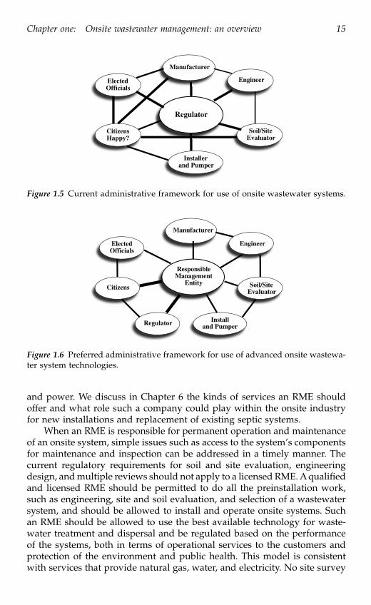
We now have the technologies that can achieve both of these require-ments in a cost-effective manner. However, we are still in an infancy stagein the development of an infrastructure (similar to a public utility) that canmake these technologies available to people. Figure 1.5 shows typical septicsystem use today and the players and their roles within the onsite industry.This situation needs to change significantly, and it can change by implement-ing the concept of a responsible management entity (RME) within the onsiteindustry. Chapter 6 presents more information on the management frame-work and RME. Figure 1.6 shows the concept of using managed onsitesystems and the players and their roles within this new, evolving paradigm.
There are a few RMEs present today that offer wastewater services topeople who use small onsite systems; however, most people still have noaccess to such services. As we advance in this century, we need to seriouslyconsider how to develop a regulatory system that will allow people to getwastewater services from an RME using advanced onsite systems the waythey get other services, such as solid waste removal, telephone, cable, gas,
3029_book.fm Page 14 Wednesday, November 23, 2005 10:30 AM
Chapter one: Onsite wastewater management: an overview 15
and power. We discuss in Chapter 6 the kinds of services an RME shouldoffer and what role such a company could play within the onsite industryfor new installations and replacement of existing septic systems.
When an RME is responsible for permanent operation and maintenanceof an onsite system, simple issues such as access to the system’s componentsfor maintenance and inspection can be addressed in a timely manner. Thecurrent regulatory requirements for soil and site evaluation, engineeringdesign, and multiple reviews should not apply to a licensed RME. A qualifiedand licensed RME should be permitted to do all the preinstallation work,such as engineering, site and soil evaluation, and selection of a wastewatersystem, and should be allowed to install and operate onsite systems. Suchan RME should be allowed to use the best available technology for waste-water treatment and dispersal and be regulated based on the performanceof the systems, both in terms of operational services to the customers andprotection of the environment and public health. This model is consistentwith services that provide natural gas, water, and electricity. No site survey
Figure 1.5 Current administrative framework for use of onsite wastewater systems.
Figure 1.6 Preferred administrative framework for use of advanced onsite wastewa-ter system technologies.
Regulator
Manufacturer
Engineer
Soil/SiteEvaluator
Installerand Pumper
CitizensHappy?
ElectedOfficials
OfficialsElected
Citizens
Regulator and PumperInstall
EvaluatorSoil/Site
Engineer
Manufacturer
EntityManagementResponsible
3029_book.fm Page 15 Wednesday, November 23, 2005 10:30 AM

16 Advanced onsite wastewater systems technologies
or individual home site plat, plan review, or permit is required to set a gas,electric, or water meter or to initiate service. Homeowners are quite familiarand quite comfortable with meter readers entering their property to readand to inspect electric, gas, and water meters. Similarly in the RME modelproposed here, onsite maintenance personnel would enter properties toinspect and service the wastewater systems. An additional model providesheating and air conditioning for a home. Several manufacturers and modelsof heating and air systems are available to the consumer, and consumersmay choose to purchase long-term service plans with the heating and airprovider. Service providers enter the property to inspect and maintain heat-ing and air systems on a regular schedule.
Under the RME model for onsite systems, the role of manufacturers,engineers, soil and site evaluators, and installers can be defined in a mannerthat would result in the most efficient use of their services. Today, the require-ments of soil and site evaluation and engineering quite often do not add anyreal value to the operation of individual home and small commercial waste-water systems. Most of the current regulations for onsite systems still requirea soil and site evaluation to determine if the proposed site is suitable for anonsite system. Such pass/fail criteria for a site are not necessary because itis now possible to have a wastewater system for any site. Once a decisionis made for development in an area that is not served by a centralizedwastewater system, an onsite system RME can offer all the services necessaryfor adequate treatment and dispersal of wastewater. The environmental andpublic health regulators can then make sure that the services provided bythe RME offer safe, adequate, and proper protection to the environment andpublic health from wastewater. Regulatory agencies can do this by makingsure that the RME is using the best available technologies for wastewatertreatment and dispersal and by monitoring the performance of the onsitesystems and their impact on the environment.
The RME can also help the onsite industry to adequately weed outwastewater technologies that are poorly designed or manufactured. Atpresent, no real mechanism measures the long-term performance of smallwastewater treatment and dispersal systems. An RME that is responsible foracquiring, installing, and operating a wastewater system in a manner thatwill meet the necessary performance standards in a cost-effective way willalways strive for the best possible technology. Such a company will have aninterest in looking at a system’s ability to meet performance standards andachieve customer satisfaction. The RME will also consider a system’slong-term cost. Only with such a company can the onsite industry reallyjudge the true potential of the various systems currently manufactured.
An RME can also educate people about the environmental impacts ofwastewater and about the importance of reuse or recycling of adequatelytreated wastewater. There is tremendous interest in the use of environmen-tally friendly systems and the reuse of treated wastewater. One must, how-ever, realize that improperly managed wastewater systems can create envi-ronmental and public health problems (as can improperly managed heating
3029_book.fm Page 16 Wednesday, November 23, 2005 10:30 AM

Chapter one: Onsite wastewater management: an overview 17
and air conditioning systems). Only under a proper management frameworkcan people have access to environmentally friendly advanced wastewatersystems. An RME can also help people get the best possible wastewatersystem at the least possible cost by acquiring products and services in quan-tity.
Today, most people who apply for an onsite system permit, typically toa health department, get most of the required preinstallation services, suchas soil evaluation and design, from a health department employee, a sani-tarian, or a private consultant or practitioner. Most health departmentemployees are trained on only one type of onsite system — a septic tankdrain field system. When it is determined, however, that the soil and siteconditions are not suitable for septic systems, homeowners then must retainservices in the private sector of a consultant familiar with alternative systemsand are asked to purchase the products and services necessary to installthose systems. In some cases, unfamiliarity and low comfort level in theregulatory community with alternatives to the traditional septic systemmake it difficult to obtain a permit for systems other than traditional septicsystems. Thus, the current regulatory system is the main reason why thereare so many septic tank drain fields in the country and so few advancedonsite systems that treat wastewater to OTL 2 or better quality before dis-charge.
The process to establish an RME model in a state must start with changesin legislation. Most importantly, we need legislation that sets a time frameto phase in the use of appropriate onsite systems under the utility modeland to phase out the use of unmanaged onsite wastewater systems. Unfor-tunately, mere legislation will not alleviate the lack of knowledge about andlow comfort level with advanced treatment systems among the regulatorycommunity. Specialization within the regulatory community with profes-sionals trained and tasked with specialty wastewater systems will also berequired. Currently, most onsite wastewater regulatory programs are underdepartments of health, with environmental specialists who are the sanitari-ans whose workload include restaurant inspections, swimming pool inspec-tions, and possibly even vector control in addition to onsite wastewatersystems.
Onsite technology is ready for the 21st centuryA number of onsite systems are available for managing wastewater fromindividual homes or small businesses in areas where a centralized wastewa-ter system is not available. In addition, numerous companies offer pre-engi-neered, prepackaged treatment and dispersal systems for purchase andinstallation, with a service contract for operation and maintenance. Not allof these services are available or well developed in all parts of the U.S. Mostof the public does not have easy access to such products or services, largelydue to the state and local regulatory framework that currently exists in mostparts of the country.
3029_book.fm Page 17 Wednesday, November 23, 2005 10:30 AM

18 Advanced onsite wastewater systems technologies
A regulatory overhaul from the ground up is needed to move the onsitewastewater industry into the 21st century and to raise the overall perfor-mance standard of onsite wastewater systems from the traditional septicsystem to a real treatment and dispersal system that allows for adequatemaintenance and monitoring of performance. We discuss needs for changesin the regulatory framework in this chapter, and in Chapter 7, we proposeconcepts for regulatory programs that would really change the way onsitewastewater systems are used today and that would encourage people tostart using advanced onsite systems within the frame-work of the RMEmodel.
Advanced onsite treatment systemsRaw wastewater or septic tank effluent can be treated to treatment OTLs 2,3, or 4 using a variety of small treatment systems currently available in themarket. Such treatment technologies can be grouped into the following cat-egories:
• Aerobic treatment units (ATUs)• Suspended growth: flow-through or sequencing batch reactor• Attached growth: trickling filter with forced aeration• Combination of suspended and attached growth
• Media filters — single pass or recirculating• Sand filters• Peat filters• Foam filters• Textile filters• Rotating biological contactors• Trickling filters• Others
• Natural systems for polishing or recycling of secondary effluent• Wetlands• Greenhouse• Others
• Waterless toilets and graywater systems as alternatives to flush toilets• Composting toilet• Incinerating toilet• Chemical toilet
• Disinfection systems for disinfecting secondary or better quality ef-fluent• Ultraviolet light• Chlorination and dechlorination
3029_book.fm Page 18 Wednesday, November 23, 2005 10:30 AM

Chapter one: Onsite wastewater management: an overview 19
ATUs
As described in detail in Chapter 4, ATUs offer an alternative to septic tanks.They treat raw wastewater to OTLs 2 or higher. Some ATUs incorporate atrash tank prior to the aeration tank for primary treatment. Numerouspre-engineered ATUs are currently available. They are generally used forsites that are declared unsuitable for a septic drain field system, based onsoil and site evaluations. The National Sanitation Foundation (NSF) is oneof the testing and certification facilities to evaluate the performance of smallATUs using the American National Standards Institute/National SanitationFoundation (ANSI/NSF) Standard 40 for Class I effluent limits. In somestates, the effluent from ATUs, after further polishing and disinfection, issometimes discharged into a surface water body or on top of the ground,resulting in a point-source discharge instead of a nonpoint discharge into anadequately sized subsurface system.
Subsurface dispersal of secondary-quality effluent (OTL 2 and above) istechnically possible on sites that are not suitable for primary effluent, suchas septic tank effluent. Actually, subsurface dispersal of secondary effluentusing such techniques as filter beds or drip/spray irrigation systems canreduce the impact on the receiving environment (RE) as compared to surfacedischarge. Nutrients including nitrogen and phosphorus can be taken up byplants when secondary effluent is dispersed into the ground at a shallowdepth, typically within the top 12
″ of soil. Sites that have low-permeabilitysoil, a shallow depth to an impermeable layer or to seasonal groundwater,can be used for subsurface dispersal of effluent from adequately operatingATUs. ATUs must be operated and maintained by trained, qualified profes-sional operators to produce high-quality effluent on a permanent basis.However, when not adequately operated and maintained, any ATU, or anyother treatment system for that matter, will discharge inadequately treatedeffluent into the RE, which can cause problems.
Media filters
Media filters, as described in detail in Chapter 3, are primarily used fortreatment of septic tank effluent; however, they are sometimes used forpolishing effluent from ATUs. Although sand filters (single pass or recir-culating) are the most commonly used media filters, other types of media(such as peat, synthetic foam, or textile) have been successfully evaluatedfor treating septic tank effluent to a better-than-secondary-quality effluent.As with ATUs, we now have access to pre-engineered, prepackaged mediafilters that can be easily installed and used for advanced treatment of septictank effluent. These systems are manufactured to be as near “plug andplay” units as possible. Essentially, once installed in an excavation,plumbed, and provided with electricity to the control panel, they are readyfor startup. Instead of engineering a media filter or an ATU for smallindividual applications, it is advisable to obtain such treatment devices
3029_book.fm Page 19 Wednesday, November 23, 2005 10:30 AM

20 Advanced onsite wastewater systems technologies
from companies that market them and to use engineering resources todevelop subsurface dispersal systems that minimize the environmentalimpact. Effluent from both media filters and ATUs, after adequate disin-fection and possibly color or iron and manganese removal, can also berecycled for flushing toilets or other such nonpotable uses, thus reducingthe need for subsurface dispersal.
The performance of any media filter depends on the quality of the media,recirculation rate, volume of the recirculation tank, distribution system forspreading effluent on top of the media, and adequate ventilation of the mediafilter. Use of an effluent filter (screen) in a septic tank and regular mainte-nance of the tank is also necessary to get adequate performance of a mediafilter. Depending on the type of media used, one may need to change themedia after a certain number of years. Media filters have been demonstratedto be very effective for reducing organic and bacteriological contaminantsfrom septic tank effluent. They can also convert most nitrogen to a nitrateform (nitrification), thus maximizing the potential for plant uptake if theeffluent is adequately dispersed into a shallow root zone using a shallowtrench, drip or spray dispersal system. There is a potential for achieving ahigh degree of denitrification when recirculation through the septic tank orprocessing tank is designed into the system.
Natural systems
Natural systems such as wetlands are being used for treating septic tankeffluent from single-family homes or from communities in some parts ofthe country, mainly in southern states. The performance of wetland sys-tems depends on the design, vegetation in the wetland, climate, andoperation of the system. Such systems tend to require a large land areaand typically have little or no mechanism to adjust the performance toaccount for variation in the inflow quality. At the same time, the energyrequirement for treatment is much lower than with other options. Anadequately engineered wetland system can offer a cost-effective methodfor removing nutrients and other constituents from primary or secondaryeffluent.
The use of greenhouse systems, a wetland operated in an enclosedand controlled environment, can lower or eliminate dependence on cli-matic conditions and can offer a reliable treatment mechanism that canproduce high-quality effluent on a consistent basis. Greenhouse systemscan also be used for significantly lowering or eliminating discharge ofeffluent by using plant uptake and evapotranspiration as the primarymechanisms for assimilating effluent into the environment. Most times,natural systems can be used in a cost-effective manner for further treat-ment of secondary-quality effluent, discharge from ATUs or media filters,to reduce the impact of nutrient and bacteriological pollutants on thereceiving environment.
3029_book.fm Page 20 Wednesday, November 23, 2005 10:30 AM

Chapter one: Onsite wastewater management: an overview 21
Waterless systems
Waterless toilets such as composting or incinerating toilets can be used toreduce the quantity of wastewater generated from a facility and also tochange the quality of wastewater. However, one needs to deal with theresidual products from such a facility, either composted material or ash, forfinal disposal by using or recycling compost in a yard as fertilizer or bysending ash to a landfill. The remaining wastewater from the structure iscalled graywater (wastewater that comes from fixtures other than toilets and/or urinals), and it may be treated adequately using natural systems such aswetlands or other systems prior to subsurface dispersal. Typically, pollutantloads in graywater are greater than in effluent from well-maintained mediafilters or ATUs; hence, adequate treatment and dispersal of graywater mustnot be overlooked. Waterless toilets are an attractive option for remote,nonresidential areas, such as golf courses or rest areas in parks, where accessto both water and wastewater facilities is costly.
Chapters 3 and 4 present information on advanced onsite wastewatersystems that would allow one to use flush toilets that use water for carryingwaste away from the dwelling. The authors are quite aware that most peopleprefer modern plumbing and modern conveniences in their homes. How-ever, reduced-flow fixtures, such as showers and flush toilets, have beenaccepted by the general population, and modern washing machines anddishwashers are available that operate efficiently while at the same timerequiring less water than older models. Although these fixtures are notrequired for using onsite and decentralized wastewater systems, they areavailable methods for people to effortlessly conserve water in their homeswhile living modern lifestyles with modern conveniences. These fixtures andmeasures are also positive ways to enhance the performance of a wastewatersystem by reducing the load on the system.
Some homeowners are willing to take more drastic measures, includingnon-water-carrying toilets such as composting toilets, incinerating toilets,or other types of chemical toilets. These types of fixtures are available todayand can be used as alternatives to flush toilets. When such alternative toiletsare used, the graywater must be treated. When properly designed andoperated, advanced onsite wastewater treatment systems can be used forthe treatment of graywater. Just as with treated wastewater, treated gray-water can be either recycled or dispersed into the receiving environmentavailable onsite. If the goal is to reduce the use of clean drinking water fortoilet flushing, that may be accomplished by reusing the treated effluentfor flushing toilets in a manner similar to using composting or incineratingtoilets that do not use water for flushing waste. The first option allows thehouse to be constructed with conventional plumbing practices with suchminor changes that allows the flush tank to be filled with recycled effluentthat comes from the advanced onsite treatment system.
3029_book.fm Page 21 Wednesday, November 23, 2005 10:30 AM

22 Advanced onsite wastewater systems technologies
Disinfection systems
Effluent disinfection before discharge may be necessary when there is apotential for human contact at or near the effluent dispersal system.Typically, direct discharge of effluent into surface water or land applica-tion of effluent using spray system would require disinfection beforedischarge. Subsurface dispersal of secondary (OTL2) or better qualityeffluent may not need disinfection mainly because soil environment canbe harsh on microorganisms and they typically do not last long in thatenvironment.
Disinfection systems used before effluent discharge rely on processesthat use an agent or destroy microorganisms (bacteria, viruses, etc.) by eitherkilling them or by preventing their replication. Agents typically used fordisinfection include chlorine, ultra-violet light, ozone, or of some other chem-ical or physical nature. The wastewater must be treated to at least secondary(OTL2) or better quality before it can be adequately disinfected. A numberof pre-engineered and pre-packaged effluent disinfection systems for use inonsite systems are available.
Microorganisms in raw wastewater can be present in millions of countsper 100 milliliter, thus reducing them by 90% will still leave a large quantityin the effluent before discharge. Typically, reduction in microorganisms isreported as log-reduction rather than percentage reduction. 90% reductionrepresents one log reduction, while 99% reduction represents two log reduc-tions. If the raw wastewater has 10 million fecal coliform counts (indicatormicroorganism) and the goal is to have less than 10 fecal coliform counts inthe effluent before discharge then one need to use a disinfection systemdesigned and tested for achieving six log reductions or 99.9999% reductionin fecal coliform count. All disinfection systems require maintenance in orderto be able to disinfect the effluent in a consistent manner.
Onsite effluent dispersal systemsSmall wastewater treatment systems, just like large ones, need a mecha-nism for returning treated effluent to the hydrologic cycle. As noted earlier,subsurface dispersal (nonpoint source discharge) is the primary mecha-nism used for returning effluent from small onsite treatment systems tothe hydrologic cycle. Chapter 5 presents details on onsite effluent dispersalsystems. The three major parameters that influence the performance ofsubsurface dispersal systems are effluent characteristics, method of appli-cation, and soil and site characteristics. The first two parameters are moremanageable than the third. Highly treated effluent, when applied in smalland frequent doses (time dosing) using various methods of application,can be adequately dispersed on a variety of soil and site conditions. Thefollowing technologies are available for subsurface dispersal of effluentfrom small treatment systems:
3029_book.fm Page 22 Wednesday, November 23, 2005 10:30 AM

Chapter one: Onsite wastewater management: an overview 23
• Trenches — gravity or pressure dosed, with or without gravel• Drip — at or below grade• Spray — above ground• Filter beds — raised systems on sand-lined beds• Evapotranspiration beds — with or without storage tanks• Greenhouses — with or without storage tanks
Since most of the dispersal technologies listed above use soil as a receiv-ing medium for the partially treated effluent, soil evaluation has been anintegral part of using onsite wastewater systems. However, with the avail-ability of a variety of treatment systems, the necessary degree of treatmentcan be achieved outside the soil and thus the need for soil and site evaluation,as currently performed for septic systems, may not be necessary. Specifically,the regulatory requirements for conducting soil evaluation prior to installinga subsurface dispersal system when nonseptic onsite treatment systems areused needs changes. A variety of dispersal systems can be pre-engineered,installed, and operated on a site in a manner that provides adequate assim-ilation of up to 1000 gallons/day treated effluent within the zone of influencespecified for that system. Based on the site characteristics and environmentalsensitivity of the proposed location, an appropriate type of pre-engineereddispersal system can be selected and installed. Effluent dispersal systemsshould be selected and sized based on a site’s assimilative capacity for thedesign flow and nutrient loading, rather than based solely on soil character-istics. Soil and site conditions that are viewed as limitations for septic drainfields must not be viewed as limitations for the use of effluent dispersalsystems.
The above-mentioned onsite treatment and dispersal technologies canbe grouped into the following 11 wastewater system types; within each type,a number of different engineering designs and methods can be used toachieve the necessary performance goals on sites where the systems are used:
Table 1.3 Onsite Wastewater Systems Types
Conventional gravity septic tank effluent drain field System type IPressure-dosed septic tank effluent drain field System type IIDrip dispersal of septic tank effluent System type IIIWaterless toilets and graywater systems System type IVGravity trench for treatment level 2 or better effluent System type VPressure-dosed trench for treatment level 2 or better effluent System type VIDrip dispersal for treatment level 2 or better effluent System type VIIFilter bed for treatment level 2 or better effluent System type VIIIEvapotranspiration bed for treatment level 2 or better effluent System type IXSpray dispersal for treatment level 3 or better effluent System type XGreenhouse for treatment level 3 or better effluent System type XI
3029_book.fm Page 23 Wednesday, November 23, 2005 10:30 AM

24 Advanced onsite wastewater systems technologies
Reuse systems other than the irrigation or plant watering systems mentionedabove can take a variety of forms and are not classified in this list. Specifically,reuse for flushing toilets is not included in this categorization.
Two main parameters influence the functioning of a subsurface dispersalsystem: the depth of soil to limiting conditions (impermeable layer or sea-sonal water table) and the permeability of soil (percolation rate, hydraulicconductivity, or texture/structure). All sites may be grouped into four sitegroups based on the values of these two parameters; within each site group,parameters such as slope, landscape position, vegetation, environmentalsensitivity, and others determine the type and design of wastewater systemsappropriate for the given situation. Most state regulations for onsite systemsspecify the required limits for soil depth and permeability for the use ofseptic drain fields. Using these limits as a reference point, a four-quadrantmatrix can be developed. Figure 1.7 presents an example of such a matrixthat can be used to match wastewater system types with the site groups fora given situation. From this approach, one can see that use of certainadvanced technologies is possible regardless of soil permeability and depthto limiting conditions as long as the system owner or maintenance provideris willing to take full responsibility for the system’s performance and itseffects on public health and environmental quality.
Remote monitoring systemMost of the advanced onsite wastewater systems mentioned above anddiscussed further in this book use electromechanical devices, such as pumps,blowers, and float switches, for achieving the necessary treatment and dis-persal goals. The performance of treatment and dispersal systems dependsheavily on the reliable operation of these devices on a continuous basis. Inorder to adequately monitor the operations of these devices on a continuousbasis and detect any problems quickly, a remote monitoring system (telem-etry system) should be used. Control panels capable of operating the
Figure 1.7 Site condition and appropriate onsite wastewater system types.
Permeability – Perc Rate MPI<5 120 >240
Site Group 1System Types I - XI
Site Group 3System Types IV - XI
Site Group 2System Types V - XI
Site Group 4System Types VII - XID
epth
toli
mit
ing
cond
itio
ns–
feet
>7
4
<1
3029_book.fm Page 24 Wednesday, November 23, 2005 10:30 AM

Chapter one: Onsite wastewater management: an overview 25
electromechanical devices as well as reporting the conditions of these devicesto a central computer using telephone lines or other means of communicationare now available for small systems. Such systems can send signals to acentral computer on a routine basis or to an operator during an emergencysituation reporting information on various parameters, such as pump runtime, duration of power outage, and high water conditions. With such remotemonitoring systems, a wastewater utility can operate a number of smallwastewater systems installed over a large geographical area in a cost-efficientmanner. This technology is familiar to municipal wastewater collection andtreatment system management entities because Supervisory Control andData Acquisition (SCADA) systems are standard equipment and softwarefor wastewater pumping stations and municipal wastewater treatmentplants. The cost of technology has reached a level that SCADA systems areavailable and affordable for onsite and decentralized systems, making decen-tralized systems appear similar to traditional centralized systems.
Operational information gathered using remote monitoring systems canbe used for preparing routine reports on the performance of the wastewatersystems and to determine the amount of wastewater managed. Such reportscan be useful for billing the user for wastewater management services andfor the regulatory agency that is responsible for ensuring adequate operationof such systems. Routine replacement of pumps and other devices can beplanned in an efficient manner based on the information gathered by remotemonitoring systems, thus minimizing or avoiding serious out-of-compliancesituations. Liquid and solid levels in tanks may be monitored to schedulepumping. Dissolved oxygen and turbidity may be easily monitored onlineand in real time to assess the treatment system’s performance, to schedulemaintenance, and to provide early detection of conditions that could lead toout-of-compliance performance of the treatment system. All of this monitoringof course is aimed at testing the effluent from the advanced treatment systemsprior to discharge to soil. As previously mentioned, collecting a representativesample of wastewater once it has dispersed into and through soil is notfeasible because it is nearly impossible to determine the treatment providedby the soil component, particularly if the soil has preferential flow paths.
Regulatory frameworkGovernment agencies that are responsible for regulating wastewater sys-tems must focus on two important issues: adequate treatment of wastewater,including dispersal and reuse of effluent, and environmental and publichealth protection from inadequately treated wastewater. Regulators mustkeep these two issues in focus and develop regulatory strategies aroundthem. The science and technologies for treating wastewater and for ensuringdrinking water quality are well established. Regulatory programs must bedeveloped to allow wastewater professionals to operate in a competitivemarketplace to offer wastewater services in a cost- effective and environ-mentally sound manner using onsite systems. Unfortunately, such a regu-
3029_book.fm Page 25 Wednesday, November 23, 2005 10:30 AM

26 Advanced onsite wastewater systems technologies
latory framework does not currently exist for small onsite systems. Today,regulatory agencies responsible for onsite systems are more involved withpreinstallation issues that typically have less direct implications on thelong-term performance of small wastewater systems. For a utility to func-tion and offer wastewater solutions to the public, the regulatory frameworkmust change 180 degrees. We need a solution-driven, performance-basedregulatory framework with heavy emphasis on postinstallation issues suchas monitoring and inspection of the system operations and the environmentas well as education and training.
Figure 1.8 shows the life of a typical onsite wastewater system placedon a timeline and what we see today is that majority of the time involvedby regulators and consultants is before the system is used, i.e., before the“first flush” when the risk to public health or to the environment is nilbecause there is no wastewater to deal with. The time required for allpre-installation activities is insignificant (a few weeks to months) comparedto the lifetime of the system during which the system is expected to performwithin its specifications and produce effluent. Typically, both the regulatoryand the consultant community walks away from the onsite system right afterthe “first flush” happens and the system becomes owner’s responsibilityduring the operation period. All onsite systems when used have potentialto fail unless they are operated and maintained following the designer’s andmanufacturer’s recommendations. Thus there is a tremendous need at leastfor the regulatory community to shift their involvement with the onsitesystem to its post-installation time period during which the system truly canhave effects on public health and environmental quality. Regulatory involve-ment during the pre-installation period does not result into much of avalue-added service to anyone.
Figure 1.8 Life of an onsite wastewater system, activities performed, and time period.Source: This concept drawing was developed by Donald J. Alexander, Director, Di-vision of Onsite Water and Sewage Services, Virginia Department of Health.
3029_book.fm Page 26 Wednesday, November 23, 2005 10:30 AM
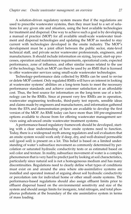
Chapter one: Onsite wastewater management: an overview 27
A solution-driven regulatory system means that if the regulations areused to prescribe wastewater systems, then they must lead to a set of solu-tions for any given site and situation, using the best available technologiesfor treatment and dispersal. One way to achieve such a goal is by developinga manual of practice (MOP) for all available small-scale wastewater treat-ment and dispersal technologies and updating the MOP as needed to staycurrent with technologies developed in the onsite industry. The MOP’sdevelopment must be a joint effort between the public sector, state-leveltechnical staff, and private sector wastewater professionals, engineers, andmanufacturers. It should include information on sizing, layout, start-up pro-cesses, operation and maintenance requirements, operational costs, expectedperformance, zone of influence, and other similar issues related to the useof the technology. Such an MOP can then be used by an RME that is licensedto offer wastewater services using small-scale wastewater technologies.
Technology-performance data collected by RMEs can be used to reviseor delete MOP content. Only regulated RMEs will have an interest in lookingat wastewater systems’ abilities on a long-term basis to meet the necessaryperformance standards and achieve customer satisfaction at an affordablecost. Thus, the best source for information on the long-term use of a tech-nology can be the RMEs. Since at present very few RMEs are in operation,wastewater engineering textbooks, third-party test reports, sensible ideasand claims made by engineers and manufacturers, and information gatheredfrom the EPA and demonstration projects are available to develop the firstversion of the MOP. An RME today can have more than 100 pre-engineeredoptions available to choose from for offering wastewater management ser-vices using advanced onsite wastewater treatment systems.
A performance-based regulatory framework should be developed, start-ing with a clear understanding of how onsite systems need to function.Today, there is a widespread myth among regulators and soil evaluators thatan onsite system would work only if deep, dry, and well-drained permeablesoil (good soil) is present on a lot. This belief is based on a limited under-standing of water’s subsurface movement as commonly determined by per-colation or saturated hydraulic conductivity tests or as estimated based onsoil color and texture. In reality, subsurface movement of water is a complexphenomenon that is very hard to predict just by looking at soil characteristics,particularly since natural soil is not a homogeneous medium and has manydiscontinuities. Regulations need to clearly define what types of conditionsmust exist on and around the area where site-assimilative systems areinstalled and operated instead of arguing about soil hydraulic conductivityor percolation rate for individual home or other small onsite systems. Theperformance-based regulations should also assign effluent limits prior toeffluent dispersal based on the environmental sensitivity and size of thesystem and should assign limits for inorganic, total nitrogen, and total phos-phorus pollutants at the boundary of the site assimilative system in termsof mass loading.
3029_book.fm Page 27 Wednesday, November 23, 2005 10:30 AM

28 Advanced onsite wastewater systems technologies
The boundary around a nonpoint source discharge system can be viewedas the zone of influence for the site assimilative system. By defining the zoneof influence, we can move away from needing regulations on soil and sitecriteria and setback distances and can allow the industry to develop newtechnologies with smaller and smaller zones of influence. A recycle and reusesystem, such as flushing toilets that use effluent and recycle effluent for plantgrowth in a greenhouse, would have the smallest zone of influence — 0 ft.around the greenhouse. A lined “evapo-transpiration” ET bed may have azone of influence of 0 ft. below the system and 10 ft. around the system.Water quality outside the zone of influence for any dispersal system mustbe no different from rain or surface water quality allowed for public contact.Adequate penalties must be enforced when predefined standards for effluentor mass loading of pollutants are violated by the utilities or RME’s.
A performance standard should also include customer satisfaction interms of the overall wastewater services offered by the RME. Customersatisfaction can be measured based on such parameters as sewage back-upin the house, odor or noise nuisance, surfacing of effluent in the yard, andunattended alarm calls that result from inadequate operation of a system.The performance-based regulations must indicate the method for establish-ing the violation and penalties for each violation. The penalties shouldinclude monetary fines and revocation of a license. Under a free-marketmodel for a utility program, there would be adequate numbers of utilitiesavailable to offer dependable services to all citizens, as long as the citizenspay the fees (sewer bills) and the regulators strictly enforce performancestandards. If an RME is allowed to continue to operate while violatingperformance standards, there will be no incentive to offer wastewater ser-vices using adequate treatment and dispersal technologies. An RME shouldbe informed about the expected performance standards, methods for mea-suring performance, and the consequences for not meeting the standards.At the same time, the management entity must establish a legal frameworkthat gives them adequate authority to collect service fees and to take actionsagainst those who do not pay these fees.
Thus, the use of small wastewater systems to effectively recycle andreuse adequately treated effluent onsite with minimum degree of collectionwill be the method of choice for wastewater treatment in the 21st century.Many technologies for treatment and effluent dispersal are currently avail-able and new ones are currently being developed. Once the infrastructurefor operation and management of these technologies is established and theperformance-based regulatory framework is adapted nationwide, exten-sive application of small-scale wastewater treatment technologies will bepossible.
3029_book.fm Page 28 Wednesday, November 23, 2005 10:30 AM

Chapter one: Onsite wastewater management: an overview 29
ReferencesU.S. Environmental Protection Agency. “Onsite Wastewater Treatment Systems Man-
ual,” EPA 625-R-00-008. Cincinnati, OH: U.S. EPA Publication Clearinghouse,2002. http://cfpub.epa.gov/owm/septic/guidelines. cfm #7489.
U.S. Environmental Protection Agency. “Voluntary National Guidelines for Manage-ment of Onsite and Clustered (Decentralized) Wastewater Treatment Sys-tems,” EPA 832-B-03-001. Cincinnati, OH: U.S. EPA PublicationClearinghouse, March 2003.
U.S. Environmental Protection Agency. “Response To Congress On Use Of Decen-tralized Wastewater Treatment Systems,” EPA 832-R-97-001b. Washington,DC. Office of Wastewater Management, April 1997.
U.S. Census Bureau. GCT-PH1. Population, Housing Units, Area, and Density. 2000Data Set. Web location: http://factfinder.census.gov/servlet/GCTTable
3029_book.fm Page 29 Wednesday, November 23, 2005 10:30 AM

This page intentionally left blank

31
chapter two
Decentralized wastewater solutions
Introduction
Society today has widely accepted the importance of adequate wastewatertreatment prior to discharge as opposed to discharge of untreated wastewa-ter. Wastewater treatment prior to discharge is necessary to ensure protectionof water quality and to reduce requirements for treatment of potable water.As mentioned in Chapter 1, during the 19th and the 20th centuries, the useof centralized collection systems was viewed as a cost-effective permanentconcept for wastewater treatment, while the use of conventional onsite sys-tems, typically septic systems, was viewed as a temporary solution for areasoutside the reach of centralized collection systems. By the end of the 20thcentury, wastewater professionals realized that centralized collection andtreatment is not the only way for managing wastewater and it is impossibleto extend centralized collection systems to many areas where new growthis occurring. Rural “electrification” (extending the central electric servicegrid to all of the populace) is no longer the model for serving the entirepopulation of the U.S. with adequate wastewater collection, treatment, andeffluent dispersal. Decentralized wastewater solutions can and will play animportant role for managing wastewater in the future. Thus, advanced onsitewastewater systems technologies offer alternatives not only to conventionalseptic systems but also to centralized wastewater solutions.
In this chapter, we explain what the term decentralized wastewater solution
means, how it differs from centralized wastewater and conventional septicsystem solutions, and how to look at wastewater within the framework ofdecentralized wastewater solutions.
3029_book.fm Page 31 Wednesday, November 23, 2005 10:30 AM

32 Advanced onsite wastewater systems technologies
The term decentralized
The term decentralized wastewater solution
has several aliases, including on-lotsystem, onsite system, individual wastewater system, cluster system,
and commu-nity system.
The main idea behind decentralized wastewater solutions is tomanage (treat and disperse or reuse) wastewater at or near the place whereit is produced. Centralized wastewater solutions manage the wastewater ina central location that typically is far away from the place where it is pro-duced. The other main difference between decentralized and centralizedwastewater solutions is in terms of the receiving environment into whichthe effluent (treated wastewater) is released. Centralized wastewater systemstypically release effluent into surface water bodies, such as oceans, rivers,streams, or creeks, whereas decentralized wastewater systems typicallyrelease effluent into soil or on top of land.
Why does one need to consider the use of decentralized wastewatersystems? There are many reasons. For example, many old septic systems arenot working correctly and sewage is seen on top of drain fields or sewageis backing up in homes. The sewer system that was supposed to arrive in aparticular area just is not coming or citizens do not want it to come. Someoneis planning to build a new home or develop a business in the area whereyou cannot get a permit to install a conventional septic system because theland does not percolate (“perc”), or poor water quality is observed in lakesor other surface water bodies resulting from a large number of malfunction-ing septic tank systems that have been in use for decades.
For new developments, it is not uncommon for the nearest centralizedmunicipal wastewater collection and treatment systems to be too far awayto be economically accessible. In rapidly developing areas, municipal collec-tion and treatment systems simply have not kept pace to provide capacityfor the population growth. Decentralized systems can provide developerswith wastewater collection and treatment solutions. For many developerswho want to maximize lot density, decentralized solutions in the form ofcluster collection treatment and dispersal systems provide a means to max-imize density and meet the wastewater needs necessary to develop. In somecases, developers would like to provide “green” development by reusingwater rather than flushing it down the sewer and not being able to recoverany of its value. The wastewater using advanced onsite wastewater systemstechnologies can easily be treated and reused for irrigation of green spacewithin the development. For areas where water is a precious commodity,and homeowners enjoy having green lawns, reusing treated wastewatereffluent provides a means to achieve this goal and, at the same time, recoverthe value of water rather than throw it down the sewer.
In some areas of the U.S., homeowners are currently being rewardedtens of thousands of dollars to remove their lawns and replace their grasswith xeriscaping in order to reduce water usage. At the same time, in thesesame areas, sewage is simply being dumped down the sewers and treatedat great expense so that it can be disposed of into surface water bodies. In
3029_book.fm Page 32 Wednesday, November 23, 2005 10:30 AM

Chapter two: Decentralized wastewater solutions 33
some cases, rural water districts have responded to their patrons by provid-ing managed decentralized wastewater systems, while at the same timegenerating additional revenue for the water district. Areas within thesedistricts have seen a surge in growth because developers are able to provide“city water” and “city sewers” to homeowners and developers.
If for any of the aforementioned reasons, or for other similar reasons,you want to address wastewater needs using decentralized wastewater sys-tems, you now can do so using advanced onsite wastewater systems tech-nologies. Use of these technologies have only two conditions: you must havean adequate management entity present in your area that can own andoperate the technologies and you must have a legal and regulatory frame-work that recognizes the use of advanced onsite wastewater systems withmanagement. We discuss more about the management entity and legal andregulatory framework in Chapters 6 and 7.
The decentralized wastewater management solutions are presented aspositive developments for rural areas. Although the authors agree, as domost people, that successful wastewater treatment with subsequent dispersalof treated water to the hydrologic cycle is a positive and healthy goal,planning commissions have used lack of adequate wastewater collection,treatment, and dispersal as a method to prevent urban sprawl and uncon-trolled development in rural and suburban areas. With the advent of feasible,easily achievable wastewater collection and treatment for decentralized sys-tems, planning commissions can no longer use wastewater as a mechanismor an excuse to control growth. Decentralized wastewater technology has“grown up” and taken that excuse away from planners. This puts planningcommissions in the unfortunate and politically unpopular position of havingto pass ordinances that limit growth on its face value rather than usingwastewater regulatory agencies as their enforcement department for con-trolling growth. We propose ideas for planning with managed decentralizedonsite systems in Chapter 8.
Centralized versus decentralized solutions
The main objective of any wastewater solution (centralized or decentralized)is to adequately treat wastewater before releasing effluent into the environ-ment. The cost of wastewater management systems is always the main issuein any public or private decision-making process. What is an appropriatecost for wastewater management? The answer depends on many factors,including the level of treatment necessary prior to discharge and the overallsocioeconomic standards of the location. Typically, water and wastewaterprojects are viewed as public projects, and they are funded by either grantor low-interest loan funds, especially when centralized solutions areemployed. The total capital cost of any such project is divided among theusers and charged as connection or hook-up fees, and operating costs arecharged based on usage.
3029_book.fm Page 33 Wednesday, November 23, 2005 10:30 AM
34 Advanced onsite wastewater systems technologies
Components of wastewater systems
The three basic components of any wastewater system are collection, treat-ment, and disposal (dispersal) systems. Of these three components, collectionis the least important for treatment of wastewater. In the past, collection wasa necessary and important component of wastewater systems mainlybecause the use of advanced treatment technologies was not cost-effectivewhen employed for treating small quantities of wastewater. However, wenow have access to wastewater treatment technologies that can treat waste-water in small quantities and meet the necessary discharge standards in acost-effective manner, thus collection of large quantities of wastewater inone central location for treatment of an entire city’s or region’s wastewateris no longer needed. Wastewater solutions can now be offered using decen-tralized, small-scale systems with a cost-effectiveness similar to what wasonce only possible using a centralized, large-scale system. Granted, tradi-tional wastewater collection and treatment systems are exactly the correctsolution in areas where housing and business density and numbers makesthis traditional approach economically superior; however, in less denselypopulated areas, the traditional approach may not be the best solution.
Categorizing decentralized and centralized systems
There are no well-defined standards for quantitatively determining whethera proposed wastewater solution can be viewed as a decentralized or central-ized system. We propose that if the capital and operational costs allocatedto the collection components (such as sewer lines and pump stations) of awastewater solution system are less than 25% of the total project costs, thenthe solution may be viewed as a decentralized wastewater solution. Byminimizing the costs associated with collection of untreated wastewater, onecan maximize the capital and operational funding for wastewater treatmentand effluent dispersal and reuse components of the system. If you think thatthe capital costs for your proposed new wastewater system are too much,we suggest that you find out the costs associated with the collection com-ponent of the entire system; if it is more than 25% of the total cost, youshould consider decentralized wastewater systems to meet your demand forwastewater treatment.
The other key factor of a decentralized wastewater solution is the methodby which and the receiving environment in which the effluent is releasedback into the environment. Decentralized wastewater systems offer alterna-tives to surface water discharge of effluent. This is very important for com-munities that rely primarily on groundwater as their source of drinkingwater. Treating wastewater onsite and dispersing effluent using land-basedeffluent dispersal systems can recharge groundwater, thus offering a sustain-able source of fresh water to communities. In addition, land-based effluentdispersal technologies can reap the benefits of soil as a natural filtrationmedium and a buffer between the effluent and the source water, which is
3029_book.fm Page 34 Wednesday, November 23, 2005 10:30 AM

Chapter two: Decentralized wastewater solutions 35
typically not possible when effluent is dispersed into surface water. Anadditional benefit for communities and other areas dependent on groundwater as a source of drinking water is that, by providing measurable, effec-tive, managed treatment of sewage (as contrasted to traditional septic tankdrain fields), groundwater is protected from unknown contaminants fromseptic tanks. Rural water districts reap the benefits of well-head protectionby providing decentralized wastewater systems to their patrons.
The science of wastewater
For both decentralized and centralized wastewater solutions, it is importantto understand the science behind wastewater treatment and wastewatertreatment classification schemes. Wastewater treatment is important andnecessary to minimize pollution from discharged effluent into the environ-ment. However, what is pollution? There are many technical and legal def-initions of the term pollution.
Technically, pollution
means undesirable oradverse environmental conditions caused by the discharge of untreated orinadequately treated wastewater into an environment. Since matter can nei-ther be created nor destroyed, from a very fundamental viewpoint, pollutionis a natural resource that is misplaced.
Many states have legal definitions of the term pollution.
For example, inVirginia, the State Water Control Law of Virginia § 62.1-44.3 states:
“Pollution” means such alteration of the physical, chemical orbiological properties of any state waters as will or is likely tocreate a nuisance or render such waters (a) harmful or detrimentalor injurious to the public health, safety or welfare, or to the healthof animals, fish or aquatic life; (b) unsuitable with reasonabletreatment for use as present or possible future sources of publicwater supply; or (c) unsuitable for recreational, commercial, in-dustrial, agricultural, or other reasonable uses, provided that (i)an alteration of the physical, chemical, or biological property ofstate waters, or a discharge or deposit of sewage, industrial wastesor other wastes to state waters by any owner which by itself isnot sufficient to cause pollution, but which, in combination withsuch alteration of or discharge or deposit to state waters by otherowners, is sufficient to cause pollution; (ii) the discharge of un-treated sewage by any owner into state waters; and (iii) contrib-uting to the contravention of standards of water quality dulyestablished by the Board, are “pollution”.
Pollution scale
In order to define the term pollution
in a quantitative (objective) manner,rather than just a qualitative (subjective) manner as defined by any environ-mental law, we propose a Pollution Scale from 0 to 10 (Figure 2-1). This scale
3029_book.fm Page 35 Wednesday, November 23, 2005 10:30 AM

36 Advanced onsite wastewater systems technologies
can be used for any water-quality related project; however, in this book, weuse the scale to differentiate between drinking water and wastewater qual-ities.
It should be noted that the scale proposed here is in contrast to thecurrent, subjective, somewhat loosely defined terminology of “primary,”“secondary,” and “tertiary” treatment. The terms primary, secondary,
andtertiary
seem to be fairly loosely interpreted by professionals around the U.S.and, in fact, recently, an additional term, advanced secondary
has come intouse. We propose to define treatment levels (and therefore pollution level) interms of a measurable, quantifiable scale that ranks wastewater treatmentin terms of easily identifiable values ranging from drinking water to rawsewage. We also propose quantitative values for treatment levels and amethod to determine overall treatment level (OTL) for an advanced onsitetreatment technology. An onsite system designer’s job would be to select anadvanced onsite treatment technology that would be suitable for dischargeof effluent into the receiving environment present at a project site, thusminimizing the potential for pollution.
Water by its very nature cannot be found in its purest form. There arealways some impurities dissolved in natural water. The U.S. EnvironmentalProtection Agency (EPA) has established the acceptable drinking water qual-ity standards shown in Table 2.1 (a) and (b). Note that at the present timethere are 87 primary and 15 secondary standards for acceptable drinkingwater quality. On one extreme of the Pollution Scale, 0 indicates water thatmeets drinking water quality, in other words, the levels of all of the 102contaminants are within the limits specified in Table 2.1 (a) and (b). On theother extreme of the Pollution Scale, 10 indicates untreated (raw) wastewateralso called sewage. The basic idea behind any wastewater treatment schemeis to reduce the level of pollutants and move towards the left end of thePollution Scale.
An inverse relationship can be developed between water quality on thePollution Scale and treatment level, and terms such as raw wastewater, effluent,
and drinking water
can be defined as shown in Table 2.2. Note that in anywastewater treatment scheme, treatment up to some degree can be achievedprior to discharging effluent into a receiving environment (RE); the remainderof treatment can be achieved after dispersal into the environment by naturalactivities as well as by dilution. The treatment level necessary before dispersaldepends on the characteristics of the RE and its overall assimilative capacity.
Figure 2.1
Pollution Scale from 0 (drinking water) to 10 (sewage) for differentiatingbetween drinking water and sewage.
3029_book.fm Page 36 Wednesday, November 23, 2005 10:30 AM

Chapter tw
o:D
ecentralized wastew
ater solutions37
Table 2.1
EPA National Primary Drinking Water Standards
ContaminantMCL or TT1
(mg/l)2
Potential health effects from exposure above the MCL
Common sources of contaminant in drinking water
PublicHealthGoal
OC Acrylamide TT8 Nervous system or blood problems; Added to water during sewage/wastewater increased risk of cancer treatment
zero
OC Alachlor 0.002 Eye, liver, kidney or spleen problems; anemia; increased risk of cancer
Runoff from herbicide used on row crops
zero
R Alpha particles 15picocuries per Liter (pCi/L)
Increased risk of cancer Erosion of natural deposits of certain minerals that are radioactive and may emit a form of radiation known as alpha radiation
zero
IOC Antimony 0.006 Increase in blood cholesterol; decrease in blood sugar
Discharge from petroleum refineries; fire retardants; ceramics; electronics; solder
0.006
IOC Arsenic 0.010 as of 1/23/06
Skin damage or problems with circulatory systems, and may have increased risk of getting cancer
Erosion of natural deposits; runoff from orchards, runoff from glass & electronics production wastes
0
IOC Asbestos (fibers >10micrometers)
7 million fibers per Liter (MFL)
Increased risk of developing benign intestinal polyps
Decay of asbestos cement in water mains; erosion of natural deposits
7 MFL
OC Atrazine 0.003 Cardiovascular system or reproductive problems
Runoff from herbicide used on row crops
0.003
IOC Barium 2 Increase in blood pressure Discharge of drilling wastes; discharge from metal refineries; erosion of natural deposits
2
OC Benzene 0.005 Anemia; decrease in blood platelets; increased risk of cancer
Discharge from factories; leaching from gas storage tanks and landfills
zero
OC Benzo(a)pyrene (PAHs)
0.0002 Reproductive difficulties; increased risk of cancer
Leaching from linings of water storage tanks and distribution lines
zero
3029_book.fm Page 37 W
ednesday, Novem
ber 23, 2005 10:30 AM

38A
dvanced onsite wastew
ater systems technologies
IOC Beryllium 0.004 Intestinal lesions Discharge from metal refineries and coal-burning factories; discharge from electrical, aerospace, and defense industries
0.004
R Beta particles and photon emitters
4 millirems per year
Increased risk of cancer Decay of natural and man-made deposits of certain minerals that are radioactive and may emit forms of radiation known as photons and beta radiation
zero
DBP Bromate 0.010 Increased risk of cancer Byproduct of drinking water disinfection
zero
IOC Cadmium 0.005 Kidney damage Corrosion of galvanized pipes; erosion of natural deposits; discharge from metal refineries; runoff from waste batteries and paints
0.005
OC Carbofuran 0.04 Problems with blood, nervous system, or reproductive system
Leaching of soil fumigant used on rice and alfalfa
0.04
OC Carbon tetrachloride 0.005 Liver problems; increased risk of cancer Discharge from chemical plants and other industrial activities
zero
D Chloramines (as Cl2) MRDL=4.01 Eye/nose irritation; stomach discomfort, anemia
Water additive used to control microbes
MRDLG=41
OC Chlordane 0.002 Liver or nervous system problems; increased risk of cancer
Residue of banned termiticide zero
D Chlorine (as Cl2) MRDL=4.01 Eye/nose irritation; stomach discomfort Water additive used to control microbes
MRDLG=41
D Chlorine dioxide (as ClO2)
MRDL=0.81 Anemia; infants & young children: nervous system effects
Water additive used to control microbes
MRDLG=0.81
Table 2.1
EPA National Primary Drinking Water Standards
ContaminantMCL or TT1
(mg/l)2
Potential health effects from exposure above the MCL
Common sources of contaminant in drinking water
PublicHealthGoal
3029_book.fm Page 38 W
ednesday, Novem
ber 23, 2005 10:30 AM

Chapter tw
o:D
ecentralized wastew
ater solutions39
DBP Chlorite 1.0 Anemia; infants & young children: nervous system effects
Byproduct of drinking water disinfection
0.8
OC Chlorobenzene 0.1 Liver or kidney problems Discharge from chemical and agricultural chemical factories
0.1
IOC Chromium (total) 0.1 Allergic dermatitis Discharge from steel and pulp mills; erosion of natural deposits
0.1
IOC Copper TT7; Action Level = 1.3
Short term exposure: Gastrointestinal distress. Long term exposure: Liver or kidney damage. People with Wilson’s Disease should consult their personal doctor if the amount of copper in their water exceeds the action level
Corrosion of household plumbing systems; erosion of natural deposits
1.3
M Cryptosporidium TT3 Gastrointestinal illness (e.g., diarrhea, vomiting, cramps)
Human and animal fecal waste zero
IOC Cyanide (as free cyanide)
0.2 Nerve damage or thyroid problems Discharge from steel/metal factories; discharge from plastic and fertilizer factories
0.2
OC 2,4-D 0.07 Kidney, liver, or adrenal gland problems Runoff from herbicide used on row crops
0.07
OC Dalapon 0.2 Minor kidney changes Runoff from herbicide used on rights of way
0.2
OC 1,2-Dibromo-3-chloropropane (DBCP)
0.0002 Reproductive difficulties; increased risk of cancer
Runoff/leaching from soil fumigant used on soybeans, cotton, pineapples, and orchards
zero
OC o-Dichlorobenzene 0.6 Liver, kidney, or circulatory system problems
Discharge from industrial chemical factories
0.6
OC p-Dichlorobenzene 0.075 Anemia; liver, kidney or spleen damage; changes in blood
Discharge from industrial chemical factories
0.075
Table 2.1
EPA National Primary Drinking Water Standards
ContaminantMCL or TT1
(mg/l)2
Potential health effects from exposure above the MCL
Common sources of contaminant in drinking water
PublicHealthGoal
3029_book.fm Page 39 W
ednesday, Novem
ber 23, 2005 10:30 AM

40A
dvanced onsite wastew
ater systems technologies
OC 1,2-Dichloroethane 0.005 Increased risk of cancer Discharge from industrial chemical factories
zero
OC 1,1-Dichloroethylene 0.007 Liver problems Discharge from industrial chemical factories
0.007
OC cis-1,2-Dichloroethylene
0.07 Liver problems Discharge from industrial chemical factories
0.07
OC trans-1,2-Dichloroethylene
0.1 Liver problems Discharge from industrial chemical factories
0.1
OC Dichloromethane 0.005 Liver problems; increased risk of cancer Discharge from drug and chemical factories
zero
OC 1,2-Dichloropropane 0.005 Increased risk of cancer Discharge from industrial chemical factories
zero
OC Di(2-ethylhexyl) adipate
0.4 Weight loss, live problems, or possible reproductive difficulties
Discharge from chemical factories 0.4
OC Di(2-ethylhexyl) phthalate
0.006 Reproductive difficulties; liver problems; increased risk of cancer
Discharge from rubber and chemical factories
zero
OC Dinoseb 0.007 Reproductive difficulties Runoff from herbicide used on soybeans and vegetables
0.007
OC Dioxin (2,3,7,8-TCDD) 0.00000003 Reproductive difficulties; increased risk of cancer
Emissions from waste incineration and other combustion; discharge from chemical factories
zero
OC Diquat 0.02 Cataracts Runoff from herbicide use 0.02OC Endothall 0.1 Stomach and intestinal problems Runoff from herbicide use 0.1OC Endrin 0.002 Liver problems Residue of banned insecticide 0.002OC Epichlorohydrin TT8 Increased cancer risk, and over a long
period of time, stomach problemsDischarge from industrial chemical
factories; an impurity of some water treatment chemicals
zero
OC Ethylbenzene 0.7 Liver or kidneys problems Discharge from petroleum refineries 0.7
Table 2.1
EPA National Primary Drinking Water Standards
ContaminantMCL or TT1
(mg/l)2
Potential health effects from exposure above the MCL
Common sources of contaminant in drinking water
PublicHealthGoal
3029_book.fm Page 40 W
ednesday, Novem
ber 23, 2005 10:30 AM

Chapter tw
o:D
ecentralized wastew
ater solutions41
OC Ethylene dibromide 0.00005 Problems with liver, stomach, reproductive system, or kidneys; increased risk of cancer
Discharge from petroleum refineries zero
IOC Fluoride 4.0 Bone disease (pain and tenderness of the bones); Children may get mottled teeth
Water additive which promotes strong teeth; erosion of natural deposits; discharge from fertilizer and aluminum factories
4.0
M Giardia lamblia
TT3 Gastrointestinal illness (e.g., diarrhea, vomiting, cramps)
Human and animal fecal waste zero
OC Glyphosate 0.7 Kidney problems; reproductive difficulties Runoff from herbicide use 0.7DBP Haloacetic acids
(HAA5)0.060 Increased risk of cancer Byproduct of drinking water
disinfectionn/a6
OC Heptachlor 0.0004 Liver damage; increased risk of cancer Residue of banned termiticide zeroOC Heptachlor epoxide 0.0002 Liver damage; increased risk of cancer Breakdown of heptachlor zeroM Heterotrophic plate
count (HPC)TT3 HPC has no health effects; it is an analytic
method used to measure the variety of bacteria that are common in water. The lower the concentration of bacteria in drinking water, the better maintained the water system is.
HPC measures a range of bacteria that are naturally present in the environment
n/a
OC Hexachlorobenzene 0.001 Liver or kidney problems; reproductive difficulties; increased risk of cancer
Discharge from metal refineries and agricultural chemical factories
zero
OC Hexachlorocyclopentadiene
0.05 Kidney or stomach problems Discharge from chemical factories 0.05
IOC Lead TT7; Action Level = 0.015
Infants and children: Delays in physical or mental development; children could show slight deficits in attention span and learning abilities; Adults: Kidney problems; high blood pressure
Corrosion of household plumbing systems; erosion of natural deposits
zero
Table 2.1
EPA National Primary Drinking Water Standards
ContaminantMCL or TT1
(mg/l)2
Potential health effects from exposure above the MCL
Common sources of contaminant in drinking water
PublicHealthGoal
3029_book.fm Page 41 W
ednesday, Novem
ber 23, 2005 10:30 AM

42A
dvanced onsite wastew
ater systems technologies
M Legionella
TT3 Legionnaire’s Disease, a type of pneumonia Found naturally in water; multiplies in heating systems
zero
OC Lindane 0.0002 Liver or kidney problems Runoff/leaching from insecticide used on cattle, lumber, gardens
0.0002
IOC Mercury (inorganic) 0.002 Kidney damage Erosion of natural deposits; discharge from refineries and factories; runoff from landfills and croplands
0.002
OC Methoxychlor 0.04 Reproductive difficulties Runoff/leaching from insecticide used on fruits, vegetables, alfalfa,
livestock
0.04
IOC Nitrate (measured as Nitrogen)
10 Infants below the age of six months who drink water containing nitrate in excess of the MCL could become seriously ill and, if untreated, may die. Symptoms include shortness of breath and blue-baby syndrome.
Runoff from fertilizer use; leaching from septic tanks, sewage; erosion of natural deposits
10
IOC Nitrite (measured as Nitrogen)
1 Infants below the age of six months who drink water containing nitrite in excess of the MCL could become seriously ill and, if untreated, may die. Symptoms include shortness of breath and blue-baby syndrome.
Runoff from fertilizer use; leaching from septic tanks, sewage; erosion of natural deposits
1
OC Oxamyl (Vydate) 0.2 Slight nervous system effects Runoff/leaching from insecticide used on apples, potatoes, and tomatoes
0.2
OC Pentachlorophenol 0.001 Liver or kidney problems; increased cancer risk
Discharge from wood preserving factories
zero
OC Picloram 0.5 Liver problems Herbicide runoff 0.5
Table 2.1
EPA National Primary Drinking Water Standards
ContaminantMCL or TT1
(mg/l)2
Potential health effects from exposure above the MCL
Common sources of contaminant in drinking water
PublicHealthGoal
3029_book.fm Page 42 W
ednesday, Novem
ber 23, 2005 10:30 AM
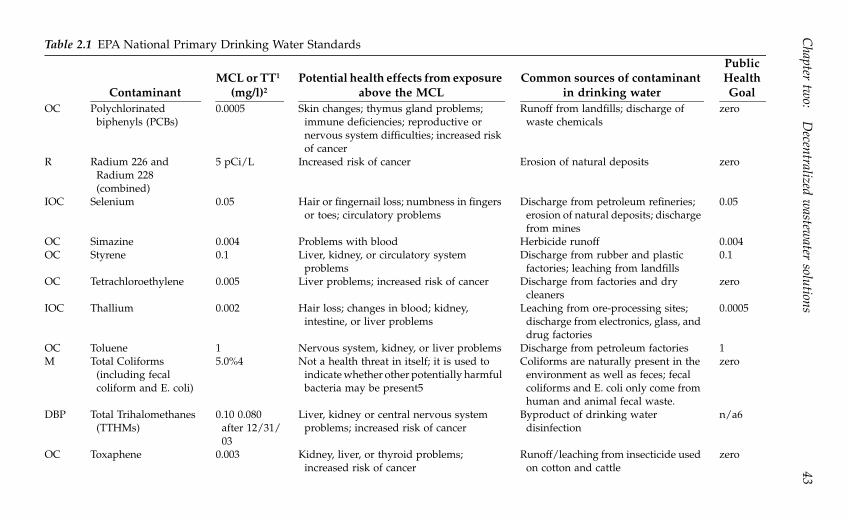
Chapter tw
o:D
ecentralized wastew
ater solutions43
OC Polychlorinated biphenyls (PCBs)
0.0005 Skin changes; thymus gland problems; immune deficiencies; reproductive or nervous system difficulties; increased risk of cancer
Runoff from landfills; discharge of waste chemicals
zero
R Radium 226 and Radium 228 (combined)
5 pCi/L Increased risk of cancer Erosion of natural deposits zero
IOC Selenium 0.05 Hair or fingernail loss; numbness in fingers or toes; circulatory problems
Discharge from petroleum refineries; erosion of natural deposits; discharge from mines
0.05
OC Simazine 0.004 Problems with blood Herbicide runoff 0.004OC Styrene 0.1 Liver, kidney, or circulatory system
problemsDischarge from rubber and plastic
factories; leaching from landfills0.1
OC Tetrachloroethylene 0.005 Liver problems; increased risk of cancer Discharge from factories and dry cleaners
zero
IOC Thallium 0.002 Hair loss; changes in blood; kidney, intestine, or liver problems
Leaching from ore-processing sites; discharge from electronics, glass, and drug factories
0.0005
OC Toluene 1 Nervous system, kidney, or liver problems Discharge from petroleum factories 1M Total Coliforms
(including fecal coliform and E. coli)
5.0%4 Not a health threat in itself; it is used to indicate whether other potentially harmful bacteria may be present5
Coliforms are naturally present in the environment as well as feces; fecal coliforms and E. coli only come from human and animal fecal waste.
zero
DBP Total Trihalomethanes (TTHMs)
0.10 0.080 after 12/31/03
Liver, kidney or central nervous system problems; increased risk of cancer
Byproduct of drinking water disinfection
n/a6
OC Toxaphene 0.003 Kidney, liver, or thyroid problems; increased risk of cancer
Runoff/leaching from insecticide used on cotton and cattle
zero
Table 2.1
EPA National Primary Drinking Water Standards
ContaminantMCL or TT1
(mg/l)2
Potential health effects from exposure above the MCL
Common sources of contaminant in drinking water
PublicHealthGoal
3029_book.fm Page 43 W
ednesday, Novem
ber 23, 2005 10:30 AM

44A
dvanced onsite wastew
ater systems technologies
OC 2,4,5-TP (Silvex) 0.05 Liver problems Residue of banned herbicide 0.05OC 1,2,4-Trichlorobenzene 0.07 Changes in adrenal glands Discharge from textile finishing
factories0.07
OC 1,1,1-Trichloroethane 0.2 Liver, nervous system, or circulatory problems
Discharge from metal degreasing sites and other factories
0.20
OC 1,1,2-Trichloroethane 0.005 Liver, kidney, or immune system problems Discharge from industrial chemical factories
0.003
OC Trichloroethylene 0.005 Liver problems; increased risk of cancer Discharge from metal degreasing sites and other factories
zero
M Turbidity TT3 Turbidity is a measure of the cloudiness of water. It is used to indicate water quality and filtration effectiveness (e.g., whether disease-causing organisms are present). Higher turbidity levels are often associated with higher levels of disease-causing micro-organisms such as viruses, parasites and some bacteria. These organisms can cause symptoms such as nausea, cramps, diarrhea, and associated headaches
Soil runoff n/a
R Uranium 30 ug/L as of 12/08/03
Increased risk of cancer, kidney toxicity Erosion of natural deposits zero
OC Vinyl chloride 0.002 Increased risk of cancer Leaching from PVC pipes; discharge from plastic factories
zero
M Viruses (enteric) TT3 Gastrointestinal illness (e.g., diarrhea, vomiting, cramps)
Human and animal fecal waste Zero
OC Xylenes (total) 10 Nervous system damage Discharge from petroleum factories; discharge from chemical factories
10
Table 2.1
EPA National Primary Drinking Water Standards
ContaminantMCL or TT1
(mg/l)2
Potential health effects from exposure above the MCL
Common sources of contaminant in drinking water
PublicHealthGoal
3029_book.fm Page 44 W
ednesday, Novem
ber 23, 2005 10:30 AM

Chapter tw
o:D
ecentralized wastew
ater solutions45
NOTES1 Definitions
• Maximum Contaminant Level Goal (MCLG)—The level of a contaminant in drinking water below which there is no known or expected risk tohealth. MCLGs allow for a margin of safety and are non-enforceable public health goals consideration. MCLs are enforceable standards.• Maximum Residual Disinfectant Level Goal (MRDLG)—The level of a drinking water disinfectant below which there is no known or expectedrisk to health. MRDLGs do not reflect the benefits of the use of disinfectants to control microbial contaminants.• Maximum Residual Disinfectant Level (MRDL)—The highest level of a disinfectant allowed in drinking water. There is convincing evidencethat addition of a disinfectant is necessary for control of microbial contaminants.• Treatment Technique (TT)—A required process intended to reduce the level of a contaminant in drinking water.
2 Units are in milligrams per liter (mg/L) unless otherwise noted. Milligrams per liter are equivalent to parts per million (ppm).3 EPA’s surface water treatment rules require systems using surface water or ground water under the direct influence of surface water to (1) disinfect
their water, and (2) filter their water or meet criteria for avoiding filtration so that the following contaminants are controlled at the following levels:• Cryptosporidium (as of 1/1/02 for systems serving >10,000 and 1/14/05 for systems serving <10,000) 99% removal.• Giardia lamblia: 99.9% removal/inactivation• Viruses: 99.99% removal/inactivation• Legionella: No limit, but EPA believes that if Giardia and viruses are removed/inactivated, Legionella will also be controlled.• Turbidity: At no time can turbidity (cloudiness of water) go above 5 nephelolometric turbidity units (NTU); systems that filter must ensure thatthe turbidity go no higher than 1 NTU (0.5 NTU for conventional or direct filtration) in at least 95% of the daily samples in any month. As ofJanuary 1, 2002, for systems servicing >10,000, and January 14, 2005, for systems servicing <10,000, turbidity may never exceed 1 NTU, and mustnot exceed 0.3 NTU in 95% of daily samples in any month.• HPC: No more than 500 bacterial colonies per milliliter• Long Term 1 Enhanced Surface Water Treatment (Effective Date: January 14, 2005); Surface water systems or (GWUDI) systems serving fewerthan 10,000 people must comply with the applicable Long Term 1 Enhanced Surface Water Treatment Rule provisions (e.g. turbidity standards,individual filter monitoring, Cryptosporidium removal requirements, updated watershed control requirements for unfiltered systems).• Filter Backwash Recycling: The Filter Backwash Recycling Rule requires systems that recycle to return specific recycle flows through all processesof the system’s existing conventional or direct filtration system or at an alternate location approved by the state
Table 2.1
EPA National Primary Drinking Water Standards
ContaminantMCL or TT1
(mg/l)2
Potential health effects from exposure above the MCL
Common sources of contaminant in drinking water
PublicHealthGoal
3029_book.fm Page 45 W
ednesday, Novem
ber 23, 2005 10:30 AM

46A
dvanced onsite wastew
ater systems technologies
4 No more than 5.0% samples total coliform-positive in a month. (For water systems that collect fewer than 40 routine samples per month, no more thanone sample can be total coliform-positive per month.) Every sample that has total coliform must be analyzed for either fecal coliforms or E. coliif two consecutive TC-positive samples, and one is also positive for E. coli fecal coliforms, system has an acute MCL violation.
5 Fecal coliform and E. coli are bacteria whose presence indicates that the water may be contaminated with human or animal wastes. Disease-causingmicrobes (pathogens) in these wastes can cause diarrhea, cramps, nausea, headaches, or other symptoms. These pathogens may pose a specialhealth risk for infants, young children, and people with severely compromised immune systems.
6 Although there is no collective MCLG for this contaminant group, there are individual MCLGs for some of the individual contaminants:• Haloacetic acids: dichloroacetic acid (zero); trichloroacetic acid (0.3 mg/L)• Trihalomethanes: bromodichloromethane (zero); bromoform (zero); dibromochloromethane (0.06 mg/L)
7 Lead and copper are regulated by a Treatment Technique that requires systems to control the corrosiveness of their water. If more than 10% of tapwater samples exceed the action level, water systems must take additional steps. For copper, the action level is 1.3 mg/L, and for lead is 0.015 mg/L
8 Each water system must certify, in writing, to the state (using third-party or manufacturers certification) that when it uses acrylamide and/orepichlorohydrin to treat water, the combination (or product) of dose and monomer level does not exceed the levels specified, as follows: Acrylamide= 0.05% dosed at 1 mg/L (or equivalent); Epichlorohydrin = 0.01% dosed at 20 mg/L (or equivalent).
Table 2.1
EPA National Primary Drinking Water Standards
ContaminantMCL or TT1
(mg/l)2
Potential health effects from exposure above the MCL
Common sources of contaminant in drinking water
PublicHealthGoal
3029_book.fm Page 46 W
ednesday, Novem
ber 23, 2005 10:30 AM

Chapter two: Decentralized wastewater solutions 47
In this chapter, we present basics of wastewater treatment, wastewater char-acterization, and classification of OTLs prior to dispersal of effluent into a RE.We assume that the reader is familiar with terms that are typically used todescribe the quality of untreated wastewater and effluent, such as biochemicaloxygen demand (BOD); total suspended solids (TSS); fats, oil, and grease(FOG); Total Kjeldahl Nitrogen (TKN); total nitrogen (TN = TKN + nitratenitrogen); total phosphorus (TP); and fecal coliform (FC). Literature cited atthe end of this chapter offers more information on these terms.
The advanced science behind wastewater treatment is presented in anumber of textbooks that are listed in the reference section of this chapter.Today, a number of pre-engineered advanced onsite wastewater treatmenttechnologies are available in the market, each is designed based on provenscientific principles of wastewater treatment.
We will not go into details of the scientific principles and theories behindwastewater treatment. Instead, we present basic information on wastewatercharacterization and outline how to calculate OTLs obtained by currently avail-able advanced onsite treatment systems.
Wastewater treatment basicsTreatability
In order to design onsite wastewater treatment systems, we must considerthe nature of the wastewater. Effluent quality depends on influent charac-
Table 2.1b
National Secondary Drinking Water Standards
National Secondary Drinking Water Standards are non-enforceable guidelines regulating contaminants that may cause cosmetic effects (such as skin or tooth discoloration) or aesthetic effects (such as taste, odor, or color) in drinking water. EPA recommends secondary standards to water systems but does not require systems to comply. However, states may choose to adopt them as enforceable standards
Contaminant Secondary Standard
Aluminum 0.05 to 0.2 mg/LChloride 250 mg/LColor 15 (color units)Copper 1.0 mg/LCorrosivity noncorrosiveFluoride 2.0 mg/LFoaming Agents 0.5 mg/LIron 0.3 mg/LManganese 0.05 mg/LOdor 3 threshold odor numberpH 6.5-8.5Silver 0.10 mg/LSulfate 250 mg/LTotal Dissolved Solids 500 mg/LZinc 5 mg/L
Source
: http://www.epa.gov/safewater/consumer/pdf/mcl.pdf
3029_book.fm Page 47 Wednesday, November 23, 2005 10:30 AM

48 Advanced onsite wastewater systems technologies
teristics. The influent characteristics, in turn, depend on the activities thattake place in the dwellings or businesses that generate the wastewater. Typ-ically, we look at the wastewater generated from a single home or a groupof homes, with the main source of the wastewater being residential activities.For other types of wastewater sources, we recommend that the onsite systemdesigner (a professional engineer or other professional educated and trainedin wastewater engineering) do a detailed study on the source activities todetermine what may be present in the raw wastewater. This is particularlyimportant for commercial establishments, in which wastewater is not gen-erated by residences.
Treatment capacity and treatment efficiency of systems are calculatedbased on influent concentrations and effluent requirements.
Efficiency = [(C
in
−
C
out
)/C
in
] 100 (2.1)
Table 2.2
Pollution Scale versus Overall Treatment Levels (OTL) before Discharge
Pollution ScaleOTL Before Discharge Treatment Level Terms
10.0 0% Raw Sewage9.0 10% Effluent8.5 15%8.0 20%7.5 25%7.0 30% 16.5 35%6.0 40%5.5 45%5.0 50%4.5 55%4.0 60%3.5 65%3.0 70%2.5 75%2.0 80% 21.5 85%1.0 90%0.9 91%0.8 92%0.7 93% 30.6 94%0.5 95%0.4 96%0.3 97%0.2 98% 40.1 99% Effluent0.0 100% 5 Drinking
Water
3029_book.fm Page 48 Wednesday, November 23, 2005 10:30 AM

Chapter two: Decentralized wastewater solutions 49
whereC in = Influent concentration (typically mg/L)C out = Effluent concentration (typically mg/L)Efficiency is expressed as a percentage (%)
Also, the treatment capacity over time for biochemical processes is usuallymodeled as a first-order equation such that:
C
t
/C
0
= e
−
kt
(2.2)
whereC
t
= Concentration at time t (typically in mg/L)C
0
= Initial concentration at time = 0 (typically in mg/L)k = Reaction rate constant (typically in days
-1
)t = time (typically in days)
For the purposes of explaining the importance of wastewater characteristicshere, wastewater strength (concentration of contaminants), the availabilityof contaminants as a food source, and the characteristic of being easilymetabolized or difficult to metabolize are all important factors to considerfor designing treatment processes. Treating all wastewater as if it is residen-tial wastewater can have disastrous results.
The source of the wastewater influences the characteristics of the wastestream. In general, we can categorize the source as residential, municipal,commercial, industrial, or agricultural. Tables documenting historicallyaccepted values for wastewater characteristics are available for domesticwastewater. Untreated domestic wastewater has different characteristicsfrom septic tank effluent. Septic tank effluent from a tank with an effluentscreen (effluent filter) has different characteristics from unscreened effluent.Grinder pump effluent has different characteristics from any of the others.Wastewater from commercial sources, such as restaurants, schools, super-markets, hospitals, hotels, and convenience stores with food service; carwashes; beauty salons; and other types of establishments, can have charac-teristics specific to the wastewater-generating activities conducted as part ofthe business.
Typical components of raw wastewater and their concentrations areshown in Table 2.3. Once the raw sewage has undergone physical and bio-logical treatment in a septic tank (Figure 2.2), its characteristics have beenaltered from those of raw sewage. Table 2.4 illustrates the characteristics oftypical domestic septic tank effluent. Most of the discussion so far, alongwith the tables and graphs presented, has focused on the concentration ofconstituents in wastewater. The concentration tables may be quite familiar.However, another set of tables is available to the designer, showing typicalflow rates from various establishments. Table 2.5, from the U.S. EPA 2002Onsite Wastewater Treatment Systems Manual,
provides information on typicalresidential wastewater flows from particular research projects. Most states
3029_book.fm Page 49 Wednesday, November 23, 2005 10:30 AM

50 Advanced onsite wastewater systems technologies
have tables within their own onsite wastewater regulations that prescribeflows to be used for design. For larger flows, such as from multiple dwellings,community systems, and subdivisions, the regulatory agencies generallyhave an estimated flow per dwelling or equivalent dwelling unit (EDU) thatis used for design. Information regarding flow rates from sources other thanresidences is shown in Table 2.6, also taken from the U.S. EPA 2002 OnsiteWastewater Treatment Systems Manual.
Table 2.7 indicates the mass loads associated with domestic wastewateron an average daily basis. Note that the concept of load is simply the productof flow times the concentration, and the load to a wastewater treatmentsystem is the mass of the constituent that is expected to be treated by thesystem.
Investigating the idea of load leads to a discussion of flows. Typical flowsfrom residential sources may be obtained from references on onsite and
Table 2.3
Raw Sewage Characteristics
Component
Concentration RangeTypical
ConcentrationTotal suspended solids, TSS 155–330 mg/L 250 mg/L5-day biochemical oxygen demand, BOD
5
155–286 mg/L 250 mg/L
pH 6-9 s.u. 6.5 s.u.Total coliform bacteria 10
8
–10
10
CFU/100mL 10
9
CFU/100mLFecal coliform bacteria 10
6
–10
8
CFU/100mL 10
7
CFU/100mLAmmonium-nitrogen, NH
4
-N 4-13 mg/L 10 mg/LNitrate-nitrogen, NO
3
-N Less than 1 mg/L Less than 1 mg/LTotal nitrogen 26–75 mg/L 60 mg/LTotal phosphorus 6-12 mg/L 10 mg/L
Source:
Onsite Wastewater Treatment Systems Manual
U.S. EPA February 2002 (EPA/625/R-00/008).
Note:
mg/L = milligrams per liter; s.u. = standard units; CFU/100 mL = colony-forming units per 100 milliliters.
Figure 2.2 Septic Tank Profile
3029_book.fm Page 50 Wednesday, November 23, 2005 10:30 AM

Chapter two: Decentralized wastewater solutions 51
decentralized wastewater systems, such as those cited in the reference sec-tions of this text. Although Table 2.5 indicates the results of some of theresearch producing ranges for estimating residential flows on a per person,average daily basis, experience from some of the decentralized wastewatersystems indicates that actual average daily flows from a single residenceranges from 150 gallons per day to approximately 200 gallons per day perresidence. These values are from cluster systems with septic tank effluent
Table 2.4 Septic Tank Effluent Characteristics
Component Concentration RangeTypical
ConcentrationTotal suspended solids, TSS 36-85 mg/L 60 mg/L5-day biochemical oxygen demand, BOD5
118-189 mg/L 120 mg/L
pH 6.4–7.8 s.u. 6.5 s.u.Fecal coliform bacteria 106–107 CFU/100mL 106 CFU/100mLAmmonium-nitrogen, NH4-N 30–50 mg/L 40 mg/LNitrate-nitrogen, NO3-N 0–10 mg/L 0 mg/LTotal nitrogen 29.5–63.4 mg/L 60 mg/LTotal phosphorus 8.1–8.2 mg/L 8.1 mg/L
Sources: U.S. Environmental Protection Agency. “Onsite Wastewater Treatment Systems Manual,” EPA 625-R-00-008. Cincinnati, OH: U.S. EPA Publication Clearinghouse, 2002, and Crites, R., and G. Tchobanoglous. Small and Decentralized Wastewater Management Systems. Boston: WCB/McGraw-Hill Companies, Inc., 1998.
Table 2.5 Residential Wastewater Flows
StudyNumber of Residences
Study Duration (months)
Study Average (gal/person/
day)Study range
(gal/person/day)Brown & Caldwell (1984)
210 66.2 (250.6)a 57.3 – 73.0(216.9 – 276.3)b
Anderson & Siegrist (1989)
90 3 70.8 (268.0) 65.9 – 75.6(249.4 – 289.9)
Anderson, et al. (1983)
25 2 50.7 (191.9) 26.1 – 85.2(98.9 – 322.5)
Mayer et al. (1999)
1188 1c 69.3 (252.3) 57.1 – 83.5(216.1 – 316.1)
Weighted average
153 68.6 (259.7)
aBased on indoor water use monitoring and not wastewater flow monitoringbLiters per person per day in parenthesescBased on 2 weeks of continuous monitoring in each of two seasons at each home
Sources: U.S. Environmental Protection Agency. “Onsite Wastewater Treatment Systems Manual,” EPA 625-R-00-008. Cincinnati, OH: U.S. EPA Publication Clearinghouse, 2002.
3029_book.fm Page 51 Wednesday, November 23, 2005 10:30 AM

52 Advanced onsite wastewater systems technologies
pressure (STEP) sewers. When cluster systems are served by traditionalgravity sewer systems, the effect of infiltration and inflow must be consid-ered in the design flows and loads. Viessman and Hammer (1998) advisethat infiltration and inflow may be as high as 60,000 gallons per day (gpd)per mile where groundwater tables are high and sewers are not tight andthat, for 8″ diameter sewers, rates of 3500 to 5000 gpd per mile represent the
Table 2.6 Typical Wastewater Flows From Various Facilities
Facility Unit
Flow gallons/unit/day Flow Liters/unit/day
Range Typical Range TypicalAirport Passenger 2-4 3 8-15 11Apartment/House
Person 40-80 50 150-300 190
Automobile service station
Vehicle served
8-15 12 30-57 45
Employee 9-15 13 34-57 49Bar Customer 1-5 3 4-19 11
Employee 10-16 13 38-61 49Boarding house
Person 25-60 40 95-230 150
Department store
Toilet room 400-600 500 1500-2300
1900
Employee 8-15 10 30-57 38Hotel Guest 40-60 50 150-230 190
Employee 8-13 10 30-49 38Industrial building (sanitary waste only)
Employee 7-16 13 26-61 49
Laundry (self service)
Machine 450-650 550 1700-2500
2100
Wash 45-55 50 170-210 190Office Employee 7-16 13 26-61 49Public lavatory User 3-6 5 11-23 19Restaurant (with toilet)
Meal 2-4 3 8-15 11
Conventional Customer 8-10 9 30-38 34Short order Customer 3-8 6 11-30 23Bar/Cocktail lounge
Customer 2-4 3 8-15 11
Shopping center
Employee 7-13 10 26-49 38
Parking space
1-3 2 4-11 8
Theater Seat 2-4 3 8-15 11
Sources: U.S. Environmental Protection Agency. “Onsite Wastewater Treatment Systems Manual,” EPA 625-R-00-008. Cincinnati, OH: U.S. EPA Publication Clearinghouse, 2002.
3029_book.fm Page 52 Wednesday, November 23, 2005 10:30 AM

Chapter two: Decentralized wastewater solutions 53
range in which most specifications fall. Photo 2.1 shows a sign where onecommunity is facing the reality of leaking conventional sewers. Photo 2.2shows overflowing sewer system near the pump station and you can see astandby generator next to the pump station.
Though average daily flow may be appropriate for estimating the sizeof a wastewater treatment system, consideration must be given to the factthat peaks occur during the course of the day. Figure 2.3 illustrates thevariability and patterns typical of a day’s residential flows. When sizingwastewater treatment systems, it is always advisable to consider peak flowsas well as average daily flows. Even with single residential systems, thesepeaks may have an effect on the treatment system. In addition to daily flowvariation, seasonal variations may also occur. Typically, wastewater treat-ment processes are sized to treat the maximum daily flow rather than simplyaverage daily flow. Maximum daily flow is the maximum flow that occursover the course of a single day, perhaps 450 gpd for a typical 3-bedroomhome. Average daily flow is the average of flow that occurs during singledays over the course of some period of time, perhaps years. This may beapproximately 150 gpd. The onsite system can then be designed for all typesof flow conditions.
Philosophically (if not particularly statistically rigorous), designingwastewater treatment system performance based on average daily flowwould imply that 50% of the time, the system is in compliance and 50% ofthe time the system is out of compliance. For this reason, treatment systemsare typically designed to produce the required effluent quality when treatingthe maximum daily flow. With cluster systems, the effect of instantaneouspeaks may be dampened because of the number of homes; however, even
Table 2.7 Waste discharge by individual on a dry weight basis
Constituent lb/capita-day gram/capita-day
Minimum Maximum Minimum MaximumBOD5 0.11 0.26 50 120COD 0.30 0.65 110 295TSS 0.13 0.33 60 150NH3 as N 0.011 0.026 5 12Organic N as N
0.009 0.022 4 10
TKN as N 0.020 0.048 9 21.7Organic P as P 0.002 0.004 0.9 1.8Inorganic P as P
0.004 0.006 1.8 2.7
Total P as P 0.006 0.010 2.7 4.5Oil and Grease
0.022 0.088 10 40
Source: Crites and Tchobanoglous, “Small and Decentralized Wastewater Management Systems,” 1998.Note: mass load (lb/day) = concentration (mg/l) x flow (gpd) x 8.34 x 10⁻⁶
mass load (gram/day) = concentration (gram/m3) x flow (m3/day)
3029_book.fm Page 53 Wednesday, November 23, 2005 10:30 AM

54 Advanced onsite wastewater systems technologies
Photo 2.1 Infiltration and Inflow Project Sign
Photo 2.2 City sewer system facing problems due to I & I – Note the over flow ofraw wastewater from the manhole and the backup power generator in the back-ground.
3029_book.fm Page 54 Wednesday, November 23, 2005 10:30 AM

Chapter two: Decentralized wastewater solutions 55
in that case, the maximum daily flow should be considered during designof any wastewater system to compensate for the effect of increased loadduring the days when large flows may occur. These considerations are soundengineering principles applied to all wastewater systems regardless ofwhether they are decentralized or traditional sewer systems. As discussedin the following paragraph, these effects have an even greater impact whena commercial system is considered. An easily understood example is aschool, in which dramatic peaks may be experienced during such periodsas recess, between classes, and during and after lunch breaks, when mealpreparation and dishwashing occur.
There are two concepts that need consideration while designing a waste-water system — hydraulic loading rate and mass loading rate. When consideringthe hydraulic loading rate, the volume of water flowing through the treat-ment process is the design parameter under consideration. For the conceptof mass loading rate, the idea of the mass or weight of a particular contaminantflowing through the system over some time is considered. Organic loadingrate, the number of pounds or kilograms of BOD per day, or solids loadingrate, the number of pounds or kilograms of TSS per day, are common massloading rates.
By combining wastewater characteristics determined by estimates fromtables or typical residential wastewater, or perhaps by sampling and analyz-ing a particular wastewater stream, with the flow rate, the wastewater loadmay be calculated. This calculation is the product of the flow rate and theconcentration as follows:
Load = Concentration × Flow x Conversion factor (2.3)
Typically, as shown in the tables provided in this text, concentration is givenin units of milligrams per liter (mg/L) and flow rate is given in units ofgallons per day (gpd). Conversion to consistent units is required to produce
Figure 2.3 Daily indoor water use patterns for single-family residences. Variabilityand patterns typical of a day’s residential flows.
T - ToiletL - LaundryB - Bath / Shower
D - Dish WashW - Water SoftenerO - Other
L/C
AP
/HR
GA
L/C
AP
/HR
MN MN3 6 9 3 6 9NTime of Day
15
10
5
0
4
3
2
1
0
Source: University of Wisconsin, 1978.
O OT T
L L
B B
D D
3029_book.fm Page 55 Wednesday, November 23, 2005 10:30 AM

56 Advanced onsite wastewater systems technologies
units of mg/day, lbs/day, or other expressions of weight (or mass) of con-taminants per time.
Some examples of facilities that produce wastewater that is dissimilarto residential (domestic) wastewater are listed Table 2.8. As illustrated by
Table 2.8 Nonresidential Wastewater Concerns
Source Waste ProductsRestaurants and convenience stores where cooking occurs (including service stations and truck stops)
Cooking oils, animal fats, detergents, cleansers, and other materials
Dairy bars Milk productsHospitals and clinics Antibiotics, antibacterial soaps and
cleansers, and pharmaceuticalsMeat processing and slaughterhouses Blood, hair, cleaning agents (possibly
acidic or caustic or both), fats, oil, and grease
Car washes Soap, grit, particulates, “road tar,” and petroleum wastes
Photography laboratories Photographic chemicalsBeauty salon Hair treatment chemicals and dyes,
soap, and shampooLaundries and dry cleaners Lint, particulate, dry cleaning agents,
acidic and caustic compounds, soaps, and dyes
Schools cafeterias that can discharge wastewater that resembles restaurant waste i.e., cooking oils, animal fats, detergents, and cleaners; chemistry and biology laboratories that can discharge chemical wastes or biological wastes; and photography and journalism laboratories that can discharge photo processing chemicals; home economics laboratories where clothes washing, cooking, or other activities may generate wastewater similar to a restaurant or a laundry i.e., cooking oils, animal fats, detergents, cleaners, bleach, clothes, lint, etc. Also, see the note above regarding TSP from “chemical dishwashers.”
Mortuaries located in rural areas served by decentralized wastewater systems may have even more particular considerations in terms of biological agents, embalming fluids, soaps, and cleansers that become part of the wastewater stream.
3029_book.fm Page 56 Wednesday, November 23, 2005 10:30 AM

Chapter two: Decentralized wastewater solutions 57
this table, wastewater may consist of any number of components that caninfluence its treatability. When considering the treatment process as afirst-order reaction, an easily biodegradable component such as blood mayhave a very large reaction rate constant, k. A less readily degradable com-ponent such as grease may have a very small reaction rate constant. A largerate constant means that if the waste is aerobically biodegraded, the oxygenuptake rate is very rapid and oxygen must be supplied at a high rate. Thisaffects the selection of the aeration method — whether passive aeration canbe used or if mechanical aerators must be chosen and, if so, the rate at whichthey must supply the air. Aeration rate affects the aerator size, horsepower,and physical delivery system, such as compressors or blowers, diffusers,pipes tubes, induced draft aerators, and so forth Although the aeration ratemust be high for an easily degradable waste, the reaction, or detention, time(and therefore the tank size) may be smaller than for a less readily degradablewaste (one with a small reaction rate constant).
For less easily biodegradable waste (very difficult wastes are sometimescalled recalcitrant), air may not need to be supplied as quickly; however,reaction time is longer. This translates into a larger tank volume — eithermore or bigger tanks — so that the wastewater can react for a longer timein order for the reaction to proceed to the same level of completion as forquickly degrading waste.
Another factor that influences reaction rate is temperature. A rule ofthumb is that the reaction rate doubles for every 10°C temperature increase.This means that oxygen uptake is more rapid at warmer temperatures,requiring air to be supplied at a higher rate. Waste degrades more quicklyat warmer temperatures, so it need not be held in the treatment system aslong when it is warm. The converse is also true: in winter, oxygen uptake islow and air need not be supplied as fast. However, at this temperature, wastetakes longer to degrade and would thus need to stay in the treatment systemlonger. The practical implication of this concept is that aerators are designedusing summer temperatures and detention tanks are designed using wintertemperatures. An illustration of the way that reaction rates affect the finalconcentration is shown in Figure 2.4.
Figure 2.5 shows the affect of the reaction rate upon the oxygen require-ment (biochemical oxygen demand). In this illustration, k1 is the fast reactionrate caused either by warm temperatures or by very easily degradable waste-water, and k2 is the slower reaction rate caused by cold temperatures or bya more difficult to degrade wastewater. In both cases, the final concentrationat the end of the treatment is the same. It simply takes longer for the wastewith k2 to reach the final concentration. Figure 2.5 illustrates the same twowastewaters and reaction rates, showing the rate at which the oxygendemand is exerted. The implication of this figure is that with a faster oxygendemand (i.e., a faster reaction rate), the oxygen must be supplied at a fasterrate but for a shorter time. With the slower reaction rate, k2, oxygen can besupplied more slowly but it must be supplied for a longer time. In bothFigures 2.4 and 2.5, if the volume of wastewater processed is the same, the
3029_book.fm Page 57 Wednesday, November 23, 2005 10:30 AM

58 Advanced onsite wastewater systems technologies
same amount is degraded, and the same of amount of oxygen is supplied.The waste is simply degraded over a longer period (longer detention time
Figure 2.4 Reaction rate and time for completion of treatment
Figure 2.5 Effect of reaction rate on final concentration and oxygen uptake rate.
Concentration
Time
C0
Cf
t0 tf(k-1)tf(k-2)
tf(k-2) = time for reaction 2 to exert its Oxygen Demand
tf(k-1) = time for reaction 1 to exert its Oxygen Demand
t0 = time at the beginning of the treatment process
BOD0 = Initial BOD exerted
BODf = Final BOD exerted
tf(k-2)tf(k-1)
2k
1k
t0
BOD0
fDBO
Time
andDemygenOx
3029_book.fm Page 58 Wednesday, November 23, 2005 10:30 AM

Chapter two: Decentralized wastewater solutions 59
= larger tank volumes), and the oxygen is supplied for a longer time and ata slower rate (fewer pounds per hour = smaller horsepower blowers) for k2.
An example of this is diluted blood with a BOD of approximately 150mg/L. As a passing note, the BOD of blood is in the range of 150,000 mg/L. Diluted blood may have a BOD similar to residential-strength wastewater,but it is very easy for microbes to degrade and, therefore, the reaction rateis very fast. It is possible that a treatment system that performs perfectlywell, producing a high-quality effluent with little odor or clogging whentreating residential wastewater, would simply be overwhelmed and couldbecome anaerobic and clogged if the diluted blood is processed. Even if thesame flow rate passes through the treatment process and the wastewaterstrength is the same, the treatment unit may not be designed to provideoxygen at a rate high enough to prevent the wastewater treatment processfrom becoming anaerobic. The result could be odors, incomplete treatment,and clogging of the treatment unit.
Temperature and FOG
Another important wastewater characteristic, although not typically listedin tables of typical properties of wastewater, is temperature. The previousdiscussion illustrates the importance of temperature on the biochemicalreactions for wastewater treatment; however, temperature may also have asignificant effect on the physical treatment processes. One common exampleof this occurs with wastewater from a restaurant or school cafeteria. Waste-water from cooking and dishwashing may have high concentrations of FOG.Typically, the method for removing grease from kitchen waste is to plumbthe kitchen drains through a grease trap. Conventional grease traps aresimply baffled sedimentation/flotation tanks that allow wastewater to slowdown long enough to let the grease float to the top. The grease trap outletis baffled to allow liquid to pass under the floating grease and flow onto thewastewater treatment system.
In order for FOG to float (to state the obvious), it must be lighter thanwater. Congealed FOG tends to be lighter than water. Grease needs to coolto congeal and separate from the water carrying the grease away from thekitchen. Some considerations for allowing FOG to separate and float includethe temperature of the water entering the grease trap, the temperature of thegrease trap, and the length of time the wastewater is allowed to stay in thegrease trap (detention time) to cool before passing onto the next wastewatercollection or treatment process. A longer detention time allows the contentsof the grease trap to cool and FOG to separate.
One of the ways to clean dishes more effectively is to increase the tem-perature of the water entering the dishwasher. Public health officials inspectkitchens and check the temperature of dishwashers as well as the time thatdishes are exposed to hot water. As a result, in order to be safe, somerestaurants run their dishwashers at very high temperatures. The result maybe that wastewater entering the grease trap is too hot, and FOG does not
3029_book.fm Page 59 Wednesday, November 23, 2005 10:30 AM

60 Advanced onsite wastewater systems technologies
have adequate detention time in the grease trap to cool and separate. FOGmay be carried onto the next treatment process, and either clog or overwhelma secondary treatment system or clog the soil absorption system. Setting thedishwasher temperature to a lower setting may allow the grease trap tooperate more effectively.
Another consideration for grease trap effectiveness is that grease trapsizing criteria in prescriptive regulations are typically from old regulationswritten when animal fat was the main form of cooking oil used in kitchens.Modern oils include liquid oils that remain liquid at room temperature andmay be more difficult to separate from wastewater than are animal fats (suchas lard and suet). Again, temperature, time, and the emulsion properties ofthe FOG in the wastewater affect the grease trap performance and may causepoor performance or failure of a downstream treatment process. Further-more, dishwashing detergents may keep the FOG suspended or emulsifiedin the waste stream, allowing it to pass through the grease trap with thewater.
An additional issue is that some dishwashers now use trisodium phos-phate (TSP) as an injected chemical cleaning agent. These dishwashers aresometimes called chemical dishwashers. Injecting TSP in the washing processallows dishwasher temperatures to be set lower to save energy. However,some anecdotal field evidence indicates that TSP emulsifies grease intosmaller particles that are not removed in grease traps or septic tanks.
Pumping a grease trap is a cost that restaurant managers, hospital man-agers, and school maintenance personnel are likely to want to decrease oreliminate. Chemical grease removal products for introduction to the greasetrap itself are available to keep the grease in suspension, allowing it to passthrough the grease trap and giving the illusion that the grease has “goneaway.” The grease may well be passing through the grease trap rather thanbeing trapped. Although this method may cut costs in the short term byreducing or eliminating the cost to pump the grease trap (and therebyimproving the manager’s profit and loss sheet), the long-term cost may wellbe repair or replacement of expensive downstream wastewater treatmentequipment or the soil absorption system. Wastewater characteristics may bemodified by adding seemingly helpful agents that result in poor performanceand possibly damage to wastewater treatment processes.
Determining wastewater characteristicsSince not all wastewater is residential wastewater, some effort may need tobe exerted to determine wastewater characteristics. Tables 2.3 and 2.4 arereasonable and reliable methods for estimating residential wastewaterstrength. For wastewater generated by establishments other than homes,some extra effort may be needed to determine wastewater characteristics.
If a system is in place and wastewater is already being generated but anew process or a modification is being designed, the waste stream can besampled and analyses can be performed to determine the wastewater char-
3029_book.fm Page 60 Wednesday, November 23, 2005 10:30 AM

Chapter two: Decentralized wastewater solutions 61
acteristics. When sampling to determine wastewater characteristics, someunderstanding of wastewater-generating processes and patterns is helpfulto design the sampling program. For example, if the wastewater is from aschool, it may be helpful to sample during the time that lunches are beingprepared and served and also during the time that dishes and the kitchenare being cleaned. In addition, it may be helpful to sample during recess atelementary schools. Possibly, a 24-hour composite sample would be helpfulif the process has the potential for being designed with equalization tankagefor a large detention time, allowing for mixing of waste. If the waste isprocessed in batches as it is generated, with little or no equalization, fluctu-ations in wastewater characteristics may be very important and sampling indiscrete increments may be the most effective way to gather information fordesign. Automatic sampling equipment eases the task of sampling in timedincrements as well as collecting a 24-hour composite. Samplers are availablethat can provide refrigeration while the sample is being collected and storedinside the sampler.
If a wastewater-generating facility is not already in place and estimatesmust be made for future wastewater treatment, similar installations (schools,convenience stores, truck stops, restaurants, etc.) may be sampled and ana-lyzed to provide a comparison for estimating wastewater characteristics.
Once wastewater samples have been properly collected, simple anal-yses for BOD, TSS, pH, acidity or alkalinity, FC, nitrogen, and nutrientsmay or may not be adequate for characterizing the waste. Some wastewatermay contain compounds that are very difficult to treat or that are toxic tothe microbes typically populating wastewater treatment systems. Somelaboratories have the capability to perform treatability studies. Essentially,the wastewater is processed in bench-scale treatment systems, and the rateof oxygen demand is measured. This is a simplification of the treatabilitystudy, but the goal is typically to determine the rate constant, sludgeproduction rate, oxygen uptake rate, and other parameters for designingthe treatment process. Examination of the wastewater under a microscopeis also a common way to see if microscopic life exists in the wastewater.If no life is observed, there is a concern that a toxin is present in thewastewater.
The number of constituents present in any wastewater will vary andwill depend on the source that is generating the wastewater. For the purposesof discussion in this book, we will consider the following six constituents ofinterest in wastewater that any advanced onsite wastewater treatment sys-tem will be designed to treat: BOD5, TSS, FOG, TN, TP, and FC.
A simple look at wastewater treatmentAs wastewater moves through a treatment system, physical and biochemicalprocesses occur. The physical process of settling is expected to occur in septictanks, trash tanks, interceptor tanks, and processing tanks of onsite septicsystems, aerobic treatment units, STEP systems, and recirculating media
3029_book.fm Page 61 Wednesday, November 23, 2005 10:30 AM

62 Advanced onsite wastewater systems technologies
systems. Some digestion, either anaerobic as in septic tanks or aerobic insome processing tanks, also occurs, degrading and digesting large organicmolecules and organic nitrogen forms, resulting in more easily digestibleorganic acids and other small carbon compounds as well as ammoniumnitrogen.
As these substrates pass into aerobic treatment mechanisms within thesecondary treatment system, microbial growth is stimulated. Organic com-pounds are used as a source of food by the microbes and converted to carbondioxide and water, as illustrated by this equation:
organic matter + O2 + microbes → CO2 + H2O + new microbes (e.g. biomass)(2.4)
This is the ideal situation, in which all organic matter is completely oxidizedto carbon dioxide and water and returned harmlessly to the hydrologic cycle.As shown in the previous equation, oxygen is required for the reaction toproceed. In well-sited and properly-functioning onsite systems, this processoccurs within the boundaries of the site upon which the system is located,and wastewater is renovated within a distance that prevents contaminationof groundwater or surface water.
Ammonium in wastewater is converted into nitrite and then to nitrateby processes using free oxygen (aerobic processes) called nitrification. First,ammonium is converted to nitrite plus hydrogen ions by a consortium ofbacteria called “Nitrosomonas”:
Step 1: NH4+ + 3/2 O2 → NO2
– + 2H+ + H2O (2.5)
Then nitrite is converted to nitrate by a consortium of bacteria called “Nitro-bacter”.
Step 2: NO2
– + 1/2 O2 → NO3
–(2.6)
As with microbial degradation of organic matter, the nitrification reactionrequires the presence of free oxygen. Thus, the system must be aerobic inorder for this process to proceed. Also, this process, known as nitrification,requires 7.1 mg of alkalinity as calcium carbonate (CaCO3) for every 1 (one)mg of nitrogen. If the nitrified wastewater encounters anoxic conditions andcontains enough organic compounds, the nitrate can be converted to nitrogengas and other gases by anaerobic processes called denitrification, as shownin this equation:
NO3 + organic compound + microbes → N2 (and other gases) (2.7)
Phosphorus may be removed either by using chemical phosphorusremoval (alum, lime, or iron sulfate compounds), by adsorption and com-
3029_book.fm Page 62 Wednesday, November 23, 2005 10:30 AM

Chapter two: Decentralized wastewater solutions 63
plexation, by biological nutrient removal (typically used in large-scale waste-water treatment systems), by dispersing the treated wastewater into soil withhigh phosphorus affinity, or by plant uptake and harvest using irrigationmethods.
Microbiological contaminants are readily removed using disinfectiontechniques, as mentioned in Chapter 1. These processes are explained indetail and with much greater accuracy in the wastewater treatment textslisted in the reference section.
Concept of overall treatment levelsIn order to classify advanced onsite wastewater treatment technologies basedon their ability to treat wastewater and reduce the constituents of interest,we define a term called overall treatment level (OTL) and establish a procedureto compute OTL based on the removal rates (reduction levels) for each ofthe constituents of interest. This approach allows manufacturers of thesetechnologies to market them in a uniform manner and allows regulators tospecify treatment levels necessary prior to discharge into any proposed RE.
The concept we present in this chapter for calculating OTL is verygeneral and can be customized to meet specific requirements. It is importantto follow the procedure presented here and, if and when necessary, customizethe input information to meet your specific requirements. Onsite treatmentsystems are designed to reduce wastewater constituents to some extent, andthe rate of reduction for different constituents can be different. Not all treat-ment systems are designed to reduce all six constituents; it is the job of adesigner to select an appropriate treatment system that meets the necessaryoverall treatment requirements before dispersal into an RE. Once a designerknows the treatment level required before discharge, the treatment necessaryafter discharge into the RE (soil) can be determined. Thus, the designer candetermine how much of the RE (land area) is needed for the proposed soiland site conditions to ensure that 100% treatment is achieved before theeffluent moves out of the design boundary of the effluent dispersal system,typically the end of the owner’s property and about 10′ below the groundsurface.
The overall treatment level achieved by an onsite wastewater treatmentsystem is defined as the weighted average of the removal rates for theconstituents of interest that the treatment system is designed to remove,typically measured as percent reduction in mass load or concentration com-pared to the levels of these constituents present in raw wastewater. Thus,OTL can be computed by a simple equation:
OTL = (2.8)weight removal raten n
n
i
*=
∑1
3029_book.fm Page 63 Wednesday, November 23, 2005 10:30 AM

64 Advanced onsite wastewater systems technologies
whereconstituents of interest are from 1 to iweightn is the relative weight given to the nth constituentremoval raten is the percent reduction (mass load or concentration) in the nth
constituent achieved by the treatment system.
In order to appropriately assign weights to the constituents of interest, wepropose that constituents be grouped in three groups:
• Group 1 — BOD5, TSS, FOG• Group 2 — TN, TP• Group 3 — FC
The following two simple rules can be used to determine the relativeweight of each constituent of interest:
• Rule 1 — All groups get equal weight, i.e., weight for each group =1/number of groups included in the calculations.
• Rule 2 — Each constituent within a group receives equal weight, i.e.,the weight for a constituent within the group = 1/number of constit-uents included in that group.
As indicated before, not all onsite treatment systems are designed totreat all constituents of interest. Thus, we need to define different scales toallow for fair computations of OTL for a given treatment system based onthe system’s treatment scheme. We propose the creation of four scales, asfollows:
• Scale A — when all groups and all constituents are included in thecalculations
• Scale B — when all groups are included but not all the constituentswithin any given group are included in the calculations
• Scale C — when not all the groups are included in the calculations,but all the constituents within the groups that are included are in-cluded in the calculations
• Scale D — when not all the groups or all the constituents within theselected groups are included in the calculations.
An example of this concept is presented in Table 2-9, along with the valuesfor weight for the constituents of interest. Note that you can change theselection of a group or a constituent following the above-mentioned rulesand recalculate the values for the weights. Once you get comfortable estab-lishing the values for weight, the next step is to establish the values forremoval rates. Currently no nationally accepted design standards foradvanced onsite treatment systems exist.
3029_book.fm Page 64 Wednesday, November 23, 2005 10:30 AM

Chapter two: Decentralized wastewater solutions 65
The septic tank, the most common onsite treatment system in the 20thcentury, has been used without any well-defined standards for removal rates.However, data on septic tank effluent quality is available in the textbookslisted in the reference section of this chapter. We used that information tocalculate removal rates for the constituents of interest by the septic tanktreatment system.
For advanced onsite treatment systems, we propose standards forremoval rates for the constituents of interest, and we hope that the industrywill start designing and testing their treatment systems against these stan-dards. We propose five treatment levels:
• Treatment level 1 — Primary treatment: typically achieved by septictanks for which available effluent quality data are used to determinelevels of reduction;
• Treatment level 2 — Secondary treatment: 90% reduction in Group1 constituents, 30% reduction in Group 2 constituents, and 90% (onelog) reduction in Group 3 constituents;
Table 2.9 Weight Calculations for Different Scales
EXAMPLE
Group Constituent Scale A Scale B Scale C Scale DGroup 1 BOD5 � � � �Group 1 TSS � � � �Group 1 FOG � �Group 2 T-N � �Group 2 T-P � �Group 3 FC � � �
Weights
Group Scale A Scale B Scale C Scale DGroup 1 0.3333333 0.333333 0.5 0.5Group 2 0.3333333 0.333333 0 0Group 3 0.3333333 0.3333333 0.5 0.5
Group Constituent Scale A Scale B Scale C Scale DGroup 1 BOD5 0.1111111 0.166667 0.166667 0.25Group 1 TSS 0.1111111 0.166667 0.166667 0.25Group 1 FOG 0.1111111 0 0.166667 0Group 2 T-N 0.1666667 0.166667 0 0Group 2 T-P 0.1666667 0.166667 0 0Group 3 FC 0.3333333 0.333333 0.5 0.5
3029_book.fm Page 65 Wednesday, November 23, 2005 10:30 AM

66 Advanced onsite wastewater systems technologies
• Treatment level 3 — Advanced secondary treatment: 95% reductionin group1 constituents, 60% reduction in Group 2 constituents, and99% (two log) reduction in Group 3 constituents;
• Treatment level 4 — Tertiary treatment: 99% reduction in Group 1constituents, 90% reduction in Group 2 constituents, and 99.99999%(seven log) reduction in Group 3 constituents;
• Treatment level 5 — Advanced tertiary treatment: 100% reduction forall constituents contained in all Groups.
This treatment scale is intended to be comfortably related to the current, lessnumerically defined terms of primary, secondary, and tertiary treatment. Thisattempt is made in order to provide the reader and user a familiar basis forcomparing the proposed scale to current terminology.
The only thing required to use the OTL concept is to develop a completelist of constituents to be considered for treatment and classify them appro-priately within each of the three groups. Note that grouping follows simplerules:
• Group 1 would have constituents that relate to organic loading, suchas BOD5, TSS, and FOG.
• Group 2 would have constituents that relate to nutrients, such as TNand TP.
• Group 3 would have microbiological constituents, such as FC.
Once the groups are determined using the two rules mentioned earlier inthis section, a weight can be assigned for each of the constituents. Then theaforementioned removal rates for each of the treatment levels may be usedto compute the OTL for any proposed scheme. A treatment system designermay select different removal rates for the constituents of interest; in otherwords, some constituents may be reduced at level 2, whereas others may bereduced at level 4, based on the quality and quantity of the RE present atthe project site. Following the aforementioned procedure, OTL may be com-puted for any treatment scheme proposed for the project. Once OTL beforeeffluent discharge is known, the designer must make certain that the rest oftreatment occurs after the effluent is discharged onsite within the designboundaries of the effluent dispersal system.
The removal rate can be calculated from the effluent data using thefollowing equation, which is similar to the efficiency equation [Equation(2.1)] mentioned earlier in this chapter:
Removal rate = [(In – Out)/In] × 100 (2.9)
expressed as % removal of mass for the constituents in Groups 1 and 2, orconcentration for the constituents in group 3.
Using this relationship, removal rates that can be expected from a septictank are computed and presented in Table 2.10. Note that the overall treat-
3029_book.fm Page 66 Wednesday, November 23, 2005 10:30 AM

Chapter two: Decentralized wastewater solutions 67
ment level for a septic tank depends on the scale one selects and the type ofremoval rates one uses for computation. The overall treatment rates foradvanced onsite treatment systems depends only on the scale one selects.Also, using this information, the effluent quality expected from an advancedtreatment system that is designed to reduce either all or some of the constit-uents of interest may be calculated.
A spreadsheet can be set up to do all these calculations. We have postedsuch a spreadsheet on our web site that you can download and use. Anexample of results from such spreadsheet calculations is presented in Table2.11. What happens when the scale is changed? The values for OTL changefor each treatment level. Table 2.12 presents the values for OTL that can beexpected for each of the four scales.
As shown in Table 2.12, OTL expected from a treatment level 1 system,such as a septic tank, varies from a minimum of 19% to a maximum of45%, depending on the number of constituents included in calculations,while that for treatment level 2 systems, such as a secondary treatmentsystem, varies from a minimum of 70% to a maximum of 90%, a significantincrease compared with septic tanks. This means that the treatment neces-sary after discharge is significantly less for any advanced treatment system(treatment levels 2, 3, 4, or 5) as compared to septic tanks (treatment level 1).
Table 2.10 Septic tank treatment levels for various constituents (Source: Crites and Tchobanoglous, “Small and Decentralized Wastewater Management Systems,” 1998)
ConstituentRaw
wastewater
Septic tank without effluent filter
Septic tank with effluent filter
Minimum Maximum Minimum MaximumBOD5 450 150 250 100 140TSS 503 40 140 20 55Oil and Grease 164 20 50 10 20TKN as N 70.4 50 90 50 90Total P as P 17.3 12 20 12 20Fecal Coliform 106-108 No significant
reductionNo significant reduction
Removal rates calculated using Equation 2.9 for Septic tank – Treatment Level 1.Septic tank without
effluent filterSeptic tank with effluent
filterConstituent Minimum Maximum Minimum MaximumBOD5 67% 44% 78% 69% TSS 92% 72% 96% 89%Oil & Grease 88% 70% 94% 88% TKN as N 29% 0% 29% 0%Total P as P 31% 0% 31% 0%Fecal Coliform 05 0% 0% 0%
Note: Removal rates for each constituent are calculated based on raw wastewater concentrationand septic tank effluent concentration. Minimum effluent concentration from septictank will give results in maximum removal rate and vise-a-versa.
3029_book.fm Page 67 Wednesday, November 23, 2005 10:30 AM

68A
dvanced onsite wastew
ater systems technologies
Table 2.11 Example of Overall Treatment Level (OTL) Computation.
Select Scale (A – D): A Note: See discussion on the scale type in “Basics” tab of the spreadsheetSeptic tank effluent: data type (1, 2, 3, 4) 4
Note: See discussion and calculations on septic tank effluent data type in “Removal Rates” tab of the spreadsheet.
Treatment Level 1
Treatment Level 2
Treatment Level 3
Treatment Level 4
Treatment Level 5
Overall Treatment Level OTL = 21% 70% 85% 96% 100%Group Treatment LevelsGroup 1 (BOD5, TSS, Oil and Grease)
21% 30% 32% 33.3% 33.3%
Group 2 (Total N and Total P) 0% 10% 20% 30% 33.3%Group 3 (Fecal coliform) 0% 30% 33% 33% 33.3%
Constituent WeightBOD5 0.1111111 44.4% 90.0% 95.0% 99.0%TSS 0.1111111 72.2% 90.0% 95.0% 99.0%Oil and Grease 0.1111111 69.5% 90.0% 95.0% 99.0%Total N 0.1666667 0% 30.0% 60.0% 90.0%Total P 0.1666667 0% 30.0% 60.0% 90.0%Fecal coliform 0.3333333 0% 90.0% 99.0% 99.99999%
aThe values for septic tank removal rates are from the Table 2.10 for septic tank without effluent filter and minimum removal rates. b The values for treatment levels 2, 3, 4, and 5 are based on proposed standards for these types of advanced onsite treatment systems.
3029_book.fm Page 68 W
ednesday, Novem
ber 23, 2005 10:30 AM

Chapter two: Decentralized wastewater solutions 69
A graphical representation of this concept is presented in Figure 2.6. Thisis the reason why we believe that the use of advanced onsite treatment withthe necessary management infrastructure can be viewed as a true alternativeto centralized collection and treatment plants, not just as an alternative toseptic tank systems or a temporary solution until a “real” sewer arrives.
Performance testing of onsite wastewater treatment systems bythird-party testing facilities is very critical to validate the design criteriaand ongoing operation and maintenance requirements in order to achievethe reduction in waste load on a continuous and consistent basis. Perfor-mance of any advanced onsite treatment system needs to be tested undercontrolled conditions, in which the quality and quantity of influent can becontrolled, as well as on a limited basis in the field where the quality andquantity of influent on a day-to-day basis cannot be controlled. A treatmentsystem that is designed to handle peak load as well as variation in loadshould perform in a satisfactory manner under both controlled and fieldconditions.
Table 2.12 OTL versus Scale
Scale
Treatment Level 1 by Septic Tank
Treatment Level 2
Treatment Level 3
Treatment Level 4
Treatment Level 5
w/o Effluent Screen
w/Effluent Screen
Max Min Max MinA 37% 21% 40% 27% 70% 85% 96% 100%B 36% 19% 39% 26% 70% 85% 96% 100%C 41% 31% 45% 41% 90% 97% 99% 100%D 40% 29% 43% 39% 90% 97% 99% 100%
Figure 2.6 Treatment outside (before discharge) versus inside soil (after discharge).
Treatment After
Treatment Before
Treatment Levels
54321
100%
90%
80%
70%
60%
50%
40%
30%
20%
10%
0% 0%4%
15%
30%
73%
100%96%
85%
70%
27%
Treatment Before & After (Scale-A)
3029_book.fm Page 69 Wednesday, November 23, 2005 10:30 AM

70 Advanced onsite wastewater systems technologies
There is some discussion that system performance may be evaluatedby “operational” analyses rather than “compliance” analyses. The differ-ence is that checking operational parameters such as pH, dissolved oxygenand turbidity, as well as sludge and scum levels and appearance may bemore cost effective than chemical sampling and analysis for compliance.It is important to note that the operation and maintenance of advancedonsite treatment technologies are very important and necessary, becausethe majority of treatment is expected to happen before effluent is dis-charged into soil. Thus, management of these treatment technologies on apermanent basis is a must and details of different management models arepresented later in this book.
Soil and site issuesIn the 21st century, all the people involved with the use of decentralized,onsite systems should shift their focus from using soil and site criteria foracceptance or rejection of a lot to using appropriate onsite treatment beforedispersal and also to operation and maintenance of the treatment systemson a permanent basis. Using appropriate advanced onsite treatment anddispersal technology, a wastewater solution can be developed for any build-able lot or site.
Installation of small, shallow trenches; filter beds; drip dispersal; sprayirrigation; or minimum or zero discharge systems can be achieved on almostany site when adequate square footage of space is available. Site suitabilityfor use of such systems is not dependent on origin (natural or fill material),type (texture and structure), depth, or color of the soil present at the site.Thus, it is very important to note here that the soil and site evaluationpractices that are currently used nationwide for approving a site for a septicsystem will need to be significantly revised when the use of advanced onsitetreatment systems is proposed.
Simply put, the purpose of a soil and site evaluation will change fromdetermining whether the proposed site is “suitable” for installation of anadvanced onsite system to determining what treatment level for various con-stituents of interest may be necessary to install the proposed advanced onsitesystem on the proposed site. Use of an advanced onsite system is possible aslong as the designer can assure that the effluent dispersal system will functionin a manner satisfactory to the user, and the management entity can assurethat the treatment system will function in a manner necessary to meet thetreatment standards on a permanent basis at a cost acceptable to the owner.
As a rule of thumb, we propose that when the use of an individual homeadvanced onsite treatment system is proposed under a responsible manage-ment entity, 6″ per year (about 450 gallons per day per acre) be consideredin the regulatory framework as the minimum hydraulic assimilative capacityof any lot. The onsite system designer’s job will then be to select an appro-priate treatment system and design an effluent dispersal system that willnot create any of the following conditions:
3029_book.fm Page 70 Wednesday, November 23, 2005 10:30 AM

Chapter two: Decentralized wastewater solutions 71
• A point-source discharge (i.e., a stream flowing out from the area)• A public nuisance (e.g., a puddle of water on or around the area
during dry weather conditions)• A health hazard from the operation of the onsite system• Groundwater or surface water contamination due to organic, inor-
ganic, or bacteriologic contaminants that are discharged into theeffluent dispersal system.
Since soil and site evaluation has been an integral part of the onsiteindustry and since most of the current regulatory programs have definedthe soil and site criteria for installation of a septic tank drain field system,in Chapter 6 we propose a step-by-step approach for redefining soil and siteevaluation processes in a way that assigns “credits” for use of advancedtreatment and effluent dispersal system on sites that may or may not besuitable for use of septic systems. Eventually, we believe that the regulatoryemphasis put on the soil and site evaluation process today will be replacedwith an emphasis on performance monitoring and inspection of advancedtreatment systems. The process of locating a site for an effluent dispersalsystem following an advanced treatment system is as simple and as inde-pendent of soil characteristics as it is for locating a site for installing theadvanced treatment system itself. Typically, the distance between the waste-water source (house or commercial dwelling) and the treatment system isminimized under the concept of a decentralized wastewater system. Simi-larly, the distance between the effluent dispersal system and the advancedtreatment system should also be minimized. Furthermore, only when efflu-ent reuse is proposed may the effluent be transported longer distances tothe sites where reuse is desired.
ReferencesBurks, B.D., and M.M. Minnis. Onsite Wastewater Treatment Systems. Madison, WI:
Hogarth House, Ltd., 1994.Crites, R., and G. Tchobanoglous. Small and Decentralized Wastewater Management
Systems. Boston: WCB/McGraw-Hill Companies, Inc., 1998.Tchobanoglous, G., and F.L. Burton. Wastewater Engineering: Treatment, Disposal, and
Reuse, 3rd ed. New York: McGraw-Hill Companies, Inc., 1991.Viessman, W., Jr. and M.J. Hammer. Water Supply and Pollution Control, 6th ed. 1998,
Addision-Wesley, Inc., Menlo Park, CA.
3029_book.fm Page 71 Wednesday, November 23, 2005 10:30 AM

This page intentionally left blank

73
chapter three
Media filters
Introduction
Media filters as discussed in this text are fixed film treatment processesdesigned to follow primary treatment in a septic tank and to provide morehighly treated effluent. The effluent produced by these filters can be disin-fected and discharged under a National Pollutant Discharge EliminationSystem (NPDES) permit, dispersed in the subsurface soil, or reused forirrigation or nonpotable household purposes. Media filters are one of theoldest types of treatment mechanisms for both water treatment and waste-water treatment. During their early use in England, sand filters were appliedto treat water prior to use as drinking water. Sand filters continue to be usedin large and small applications for water and wastewater treatment wherethey are used as pressure filters. In these cases, the media is completelysaturated and the water is ponded on top of the filters to provide adequatehead to push either the treated drinking water or pretreated wastewaterthrough the crust, or schmutzdecke (dirty floor), of material that accumulateson the filter surface. These types of filters are known as pressure filters and,although used for filtering secondary quality treated wastewater such assettled aerobic treatment plant effluent, they should not be confused withthe filters used for treating septic tank effluent.
Although media filters for wastewater treatment may perform somefunctions similar to pressure filters for water treatment, they should not beconfused with pressure filters. The physical functions of the media filter arestraining, entrapment, adsorption, and impaction. These physical phenom-ena may be quite effective at the beginning of the filters’ operation, but theymay decline and become less important as the filter matures and the bio-chemical processes become the prevalent method of wastewater treatment.
Media filters provide a fixed material for establishing a thin biologicalfilm by organisms living on the surface of the media. Wastewater passesthrough the bed and comes into contact with the attached microbial mass.The mechanism should be familiar to traditional sanitary engineers in thatone commonly encountered form of the media filter is the trickling filter.
3029_book.fm Page 73 Wednesday, November 23, 2005 10:30 AM

74 Advanced onsite wastewater systems technologies
Another relatively well-known type of packed bed filter used for wastewatertreatment is the single-pass intermittent sand filter. The organisms are in contactwith wastewater as it percolates over the surfaces and flows slowly in anunsaturated state through the media. The process requires small, frequentdoses of effluent to promote unsaturated, thin-film flow over the mediasurface. Air within the pores of the media provides oxygen transfer to theorganisms attached to the surface. In this way, aerobic organisms digestcontaminates in the wastewater as it moves slowly through the system(Figure 3.1). Aeration may be passive or active, depending on the systemdesign or loading rate. The mode of treatment is a combination of filtrationand trapping, adsorption, biological decomposition, and biochemical trans-formation.
Important to obtaining a well-treated effluent is the method of dosingthe settled wastewater onto the filter surface. Some older design guides (U.S.Environmental Protection Agency [EPA], 1980) suggest a loading rate of 5gallons per day (gpd) per square foot of media surface and recommenddosing by flooding the filter surface 2 in. deep with septic tank effluent. Thedesign produced poor-quality effluent and caused the media to clog after afew months or years of service. Some of the remedies for this malfunctioninclude rototilling the surface of the sand to break up the microbial crustand removing the media and replacing it with new media. However, withoutaddressing the dosing problems, rototilling simply allowed the crust toreform and sometimes deepen. Media removal and replacement was costlyand was merely a temporary solution until the biological clogging mat(biomat) reformed and the media become reclogged.
In this chapter, the use of small, frequent doses will be discussed. Asknowledge has progressed, designers have found that using small, frequentdoses keeps the filter unsaturated and aerobic and has improved perfor-mance and greatly extended the life of filters. Although current loading rates
Figure 3.1 Schematic of Flow and Treatment Effects on Media Particles
NUTRIENTSSS
B.O.D.CELLMASS
EXCESS
PATHOGENS
AIR
END PRODUCTS
ORGANICS
LIQUID WASTES
MASSBIOLOGICAL
MEDIA
PROCESSES AT WORK
3029_book.fm Page 74 Wednesday, November 23, 2005 10:30 AM

Chapter three: Media filters 75
may be lower than those proposed in the 1980s, the return in terms ofimproved water quality and filter life more than compensates for the costsassociated with increased filter size.
Media filters are a beneficial option for onsite systems in environmen-tally sensitive areas or areas where soils are not considered hydraulicallyacceptable for septic tank effluent. Media filters are used to produce effluentlow in biochemical oxygen demand (BOD5) and total suspended solids (TSS)that also has a greatly reduced concentration of pathogenic organisms inrelation to septic tank effluent (Table 3.1). Media filters also transform nitrog-ern by the processes explained in Chapter 2 and as shown in columns 3 and4 of Table 3.1. The increase in Dissolved Oxygen (D.O.) in the media filtereffluent (as compared to septic tank effluent) is a result of the introductionof air as illustrated in Figure 3.1.
A mature media filter is not particularly effective for phosphorusremoval. Although clean sand may be quite effective for removing phospho-rous, over time, as the filter matures, the influent phosphorus concentrationand the effluent phosphorous concentration are essentially the same (Nicholset al., 1991). Phosphorus concentrations in media filter effluent may rangefrom 4 mg/L to 20 mg/L. Many designers and researchers believe that theresulting effluent can be discharged to soils at higher rates than septic tankeffluent without developing a biomat at the infiltrative surface of the soilabsorption system. Duncan et al. (1994) showed that for highly treated efflu-ent such as that from a sand filter, a lesser depth of natural soil is requiredto complete the treatment process than with septic tank effluent. Theseexamples illustrate the principle that the treatment system is less dependenton the soil when using an advanced onsite wastewater system than whenusing a simple septic tank for treatment prior to dispersal into soil.
Theory of attached-growth wastewater treatment systemsThe media in a filter bed provides material that has a high surface area pervolume and easily passes water and oxygen. Wastewater is distributed acrossthe surface of the media. As the wastewater passes through the bed, amicrobial ecosystem establishes itself on the surface of the media in the formof a fixed film. Organisms, ranging from amoeba to larvae, establish an
Table 3.1 Typical Domestic-Strength Septic Tank Effluent And Media Filter Effluent
Treatment System
BODmg/L
TSSmg/L
Nitrate-Nmg/L
Ammonium-Nmg/L
D.O.mg/L
Fecal ColiformOrg./100 ml
SepticTank
130-250 30-130 0-2 25-60 <2 105–107
Mediafilter
5-25 5-30 15-30 0-4 3-5 102-104
Total phosphorus (P) content depends on whether detergents with high P content are used. Amedia filter does not remove much P. P concentrations in septic tank effluent and PBFeffluent may range from 4 to 20 mg/L (D.O. = Dissolved oxygen)
3029_book.fm Page 75 Wednesday, November 23, 2005 10:30 AM

76 Advanced onsite wastewater systems technologies
ecosystem in the media. This is sometimes referred to as an attached-growthprocess, in contrast to the suspended-growth process used in extended aerationactivated sludge. Fixed film reactors reduce the BOD of wastewater byexposing the organic compounds to the attached (fixed) microorganisms.Easily digestible organic material is converted to cell mass (more microor-ganisms), heat, water, and carbon dioxide as illustrated by equation 2.4 inChapter 2.
A biologically active film of organisms forms on the surface of the media.Microorganisms play an essential role in treating the wastewater as it flowsover the media surface. Certain bacteria, known as primary colonizers, attachvia adsorption to the surfaces and differentiate to form a complex, multicel-lular structure known as a biofilm. The microorganisms that form the filmover the media are nearly always present in the wastewater and generallydo not have to be introduced to the treatment system. However, for thisbiofilm to form, proper environmental conditions are required. For example,a food source must be present — organic carbon and nitrogen compoundsin the wastewater must be supplied. However, other conditions must alsobe present. A simple mnemonic for remembering the elements required forbiochemical degradation is “CHONPS café” — sometimes pronounced“Chonops Café” — which refers to carbon, hydrogen, oxygen, nitrogen,phosphorus, and small amounts of calcium and iron. Sufficient moisture isalso an important factor. Temperature, amount of readily available oxygen,and pH also play important roles. If these factors are present, a biofilm canform around a media particle. Typically, at temperatures near 200 C, a biomatmay be mature enough for nitrification within 14 to 21 days. When thetreatment system is receiving wastewater, adequate moisture is usually avail-able; however, adequate air movement through the system to provide theneeded oxygen has been deficient in some systems, particularly those thatare organically or hydraulically overloaded, as discussed in Chapter 2. Aswastewater percolates past the media and microorganisms, the biofilmgrows by entrapping organic material. During rest periods, the trappedorganic matter is digested.
Many different types of heterotrophic bacteria are found in these biofilmlayers. Calaway (1957) discovered 14 different species of heterotrophic bac-teria in different levels of a single-pass sand filter. All species were presentat all times, indicating that bacteria adapted to the environment and werecarrying on metabolic processes. These bacteria were in the upper layers, inabout the first 12 in. (30 cm), of the sand. Insufficient food in lower levelsresulted in most of the active organisms remaining in the top layer. Increasingdosing rates produced a marked increase in the number of bacterial speciesin the filter. Several researchers have shown that smaller, more frequent dosesimprove coliform removal (Emerick et al., 1997; Darby et al., 1996).
Both nitrifying bacteria (those that convert ammonium to nitrite thennitrate) and denitrifying bacteria (those that convert nitrate to nitrogen gas)are present in filter media. Although media filters are typically consideredaerobic systems, the interstitial spaces within the media provide zones
3029_book.fm Page 76 Wednesday, November 23, 2005 10:30 AM

Chapter three: Media filters 77
(microsites) of stagnation where anaerobic conditions may be present, pro-moting denitrification and therefore a net loss of total nitrogen. The netnitrogen reduction through an intermittent sand filter may be expected tobe approximately 30 percent. With loading rates at or below the recom-mended design values indicated in Table 3.2, most of the BOD is removedin the first few inches of the media and most of the ammonium is convertedto nitrate within the first foot or so (Calaway, 1957).
In addition, viruses have been found trapped within the first few inchesof media, resulting in significant virus removal in a mature media filter(Gross & Mitchell, 1990). Deeper in the media, organism populations arereduced, oxygen may be less available, and reaction rates are lower. How-ever, some nitrification appears to occur deeper, as evidenced by the factthat deeper filters provide more ammonium reduction (Bounds, 2003). Somerecent filter designs include enhanced ventilation, drafting, or forced aera-tion to ensure complete air movement throughout the depth of the filter oras a recovery mechanism if biological clogging occurs.
Some media filters are manufactured to be loaded organically andhydraulically low enough to keep the biofilm in steady-state, endogenousrespiration so that organisms in the biofilm are degraded and decomposedat the same rate that they are formed. This prevents clogging and sloughingof the biofilm. The lower portions of the filter media catch any materialsloughed from above and maintain a consistently high effluent quality. Othermedia filters resemble traditional trickling filters and are designed to beloaded at a rate that causes the biofilm to occasionally slough. The enclosurein which the filter is contained provides an integral clarifier for settling thesloughed biofilm, and the resulting sludge is typically returned to the pri-mary settling and processing tank with the recirculated effluent. Commonsense would lead a designer to understand that, eventually, the degradedsludge would need to be removed from the primary settling and processingtank. This is expected to take place when the primary tank is pumped duringroutine maintenance.
The oxygen requirement for a media filter can be estimated using theequation:
O2 = 8.34(10–6) Qi [1.2 BOD5 + 4.57 TKN] (3.1)
whereO2 = pounds of oxygen required per dayBOD5 = biochemical oxygen demand concentration reductionthrough the filter, mg/LTKN = total Kjeldahl nitrogen concentration reduction through thefilter, mg/LQi = daily (forward) flow through the filter, gpd
In some cases, the oxygen requirement is met simply by passive venting ofthe media filter unit through vents placed from the filter enclosure surface
3029_book.fm Page 77 Wednesday, November 23, 2005 10:30 AM

78 Advanced onsite wastewater systems technologies
to the bottom of the filter. Typically, the air is supplied by a passively induceddraft from the vent through sewer vent piping leading through the houseand the roof vents. This mechanism is similar to the flue of a fireplace. Inother cases, where the organic and hydraulic load is sufficiently high, andthe passive venting does not provide adequate oxygen, a mechanicallyinduced draft (blower) is provided to supply the oxygen demand to themedia filter.
Types of natural and synthetic media used for treating wastewater
The media characteristics of interest are the surface area provided by themedia upon which the biological film develops, the available pore space,and the pore space’s characteristics for air movement. Characteristics of themedia in several media filters, including some commonly used proprietaryfilters, are shown in Table 3.2.
Media filters may be classified based on the type of media used andwhether effluent passes through the filter one time or is recirculated andsubjected to multiple passes through the media. Following is a list of mediatypes that have been used, classified by how the material originates, whetheroccurring in nature or manufactured. All of the materials listed below maybe used in either single-pass or recirculation mode:
• Natural and mineral media• Sand or gravel• Expanded shale• Cinders• Limestone• Activated carbon• Peat or peat fiber • Manufactured products
• Textile fabric• Open cell foam cubes• Hard plastic• Crushed glass• Tire chips• Processed slag
The application of any of these media should be considered in terms of theirlife expectancy, whether they are expected to slough and produce biosolids,and their maintenance requirements. Manufacturers and suppliers haveexperience with and information on these factors for their particular mediafilters. Typically, manufacturers or their representatives work closely withdesign engineers to size wastewater treatment systems, including all of thetankage, pumps, clarifiers, valves, and other necessary appurtenances. The
3029_book.fm Page 78 Wednesday, November 23, 2005 10:30 AM

Chapter three:
Media filters
79Table 3.2 Media Filter Loading Rates, Dose Volumes, and Media Characteristics
TypeHyd. Load,
gpd/ft2
Org. Load lb BOD/ft2/
daDistr.
SystemDose Vol.
Gal/ft2
MediaDepthinches
Dosesper Day
MediaVoid
Space, %
Water holdingcapacity% vol.
Media Size, d10, mm
MediaSurface
Area ft2/ft3
SPSF 0.7-1.2 .0007-.0021 1/8
″ per 4-6 ft2 .05-.1 (<0.5 gal/orifice)
24 18-24 30 <10 0.3–0.6 800-1000
RSF 3-5 .002-.0083 1/8
″ per 4-6 ft2 0.1-0.5 (0.5-2 gal/orifice)
24-30 48-96 30 <7 1.5-2.5 mm 500-700
Advantextm
(textile)25-35 .04-.058 1/8 ″/0.3 ft2* 0.6-1.2 22 72-144 90 <25 N/A 2400-4800
Waterlootm
(open cell foam)11.2–16.8** .013-.016** Helical spray
nozzles@ 10 psi
0.13** 36-102 80 - 140 30 50 2-in cubes notpublished
SCATtm
(open cell foam)11-16 0.015-0.016
powerventilated
Helical spray nozzle
@ 5-8 psi
1.2–1.5 30 (min.)
notpublished
30 50 2-in cubes not published
Puraflo (peat fiber) 5.6 0.014 1/4 ” per 3–4 ft2 10-12 gal/module
24 12 90-95 50-55 not published 6
× 106
Premier Tech (peat) 4-8.6 0.005-0.01 Gravity or pump to
tipping bucket
0.03 31.5 20–80 >90% 85 .25-2.0 5x10⁵
PEATEC(Septisorb) Recirc.
(peat spheres)
6.2 notpublished
Spiral nozzles 0.2-0.3 24 90-120 60 1-2 mm sphere
Eco Pure(peat)
5.7 0.014 Gravity or pump to simulate
gravity distr.
0.3 26 20 if pumpis
used
50-60 not published not published
* For the commercial unit (AX 100), distribution is by spray nozzles covering 3-4 ft2 per nozzle.** Values are for a 3-ft deep system. The company gives design values per ft 3 instead of per ft2.Note: Conversion factors: 1 gpd/ft2=40.74 Lpd/m2; 1 lb BOD/ft2/day = 4.885 Kg/m2/day; 1 inch = 2.54 cm
3029_book.fm Page 79 W
ednesday, Novem
ber 23, 2005 10:30 AM
80 Advanced onsite wastewater systems technologies
design engineer must supply the appropriate information, such as expecteddaily flows (including peaks, average, and minimum flows), wastewaterstrength, any particular wastewater characteristics that might affect treat-ment, and some idea of the trend of the system toward growth into itsultimate expected hydraulic and organic capacity in the case of phases of asubdivision or similar development. Some systems do not perform wellwhen they are underloaded, and this may be a factor in the way that thesystem is designed and constructed. Most media filter systems used fordecentralized wastewater treatment are constructed as modular units and,therefore, may be phased in as the wastewater capacity is required.
The most commonly used types of media filters are briefly introducedhere. Design criteria and operational recommendations are discussed later.
Sand and gravel filters
Single-pass sand filters and recirculating sand filters are common types ofmedia filters that contain natural sand or gravel particles as the media forthe filter. Sand or gravel particles are screened to meet specific grain sizedistribution specifications. These specifications are designed to provide therequired surface area for bacterial attachment, with adequate void space forpassive airflow and oxygen to aerobic organisms, and sufficiently large voidsto prevent rapid clogging by the combination of filtered solids and biologicalgrowth. Single-pass sand filters generally use media with an effective sizein the range of 0.28 to 0.35 mm; recirculating sand filters, 2 to 5 mm. Inaddition, the uniformity coefficient (U.C.) of the media is important to pre-vent void spaces from being filled by small particles. A uniformity coefficientless than 4.0 is recommended; however, no evidence exists that a perfectlyuniform media (U.C. = 1.0) would be less effective than a less uniform media.
Peat filters
Several proprietary designs of media filters utilize peat or peat fiber. Thispeat may be selected from specific parts of the world to provide the desir-able characteristics. Peat has the high surface area and high-void volumeconfiguration needed for efficient packed bed filter geometry. When peatis dry, it is light (lower density) compared with such mineral media assand and can be placed into containers (called pods) for shipment to thesite. This allows the installer to simply excavate the correct size hole, setthe peat pods, plumb them, and install the appropriate electronic controls.“Plug and play” components have an advantage over sand filters in thatthe peat filters may be installed in their own pods without the necessityof constructing an enclosure for the media as part of the construction ofthe wastewater system.
Peat degrades over time and may need to be replaced after some years.The pod remains in place, with all plumbing, and the media is simplyreplaced with new peat. However, peat may provide better coliform
3029_book.fm Page 80 Wednesday, November 23, 2005 10:30 AM

Chapter three: Media filters 81
removal than do some of mineral and synthetic media. One characteristicof peat filter effluent that may be noticed is the color. The humus in thepeat may impart a slightly brownish or “tea” color to the treated effluent;however, this trait has not been found to be of any detriment to the treat-ment capability of the systems in terms of BOD, TSS, coliform, or nitrogenremoval.
Manufactured media filters
Various manufactured media are being utilized. Examples include open-cellfoam cubes, specially designed synthetic fabrics, plastic pipes, and packedtower media (typically used in air stripping towers or trickling filters).Crushed glass can be used in designs that are very similar to sand or gravelfilters. Filters with several different materials are described in Leverenz etal., 2002. Other manufactured media have been tried and may be developedfurther for use in the future. One advantage of synthetic media is the uniformcharacteristics of any particular media due to manufacturing of the mediato the same size and shape. In addition, synthetic media may be manufac-tured to provide particular hydraulic characteristics, such as conductivity,porosity, and storage capacity per unit volume. Also, the density of the mediamay be controlled. Given this control, the potential for manufacturing mediawith specific characteristics, such as lightness, provides the possibility ofpackaging treatment systems in modules that may be installed in an exca-vation as plug and play units. Then modules may be added or brought onlineas wastewater flow increases, thereby matching treatment capacity to waste-water flow and load.
Flow and load estimatesCrites and Tchobanoglous (1998) recommend the use of a per capita flowallowance and a peaking factor as a method of determining an appropriatedesign flow for a home. They use a per capita allowance of 50 gpd (200 Lpd)and a peaking factor of 2.5, resulting in a peak per capita design flow of 125gpd (475 Lpd). For a three-bedroom home having four persons in residence,this method results in a daily design flow of 500 gpd (1900 Lpd). Wastewatersystem design for small systems and individual homes is highly controlledby local regulations. Each local regulation has a procedure for determiningdesign flows or total flows for a home, or other sources of wastewater, thatmust be followed.
In addition, wastewater strength and load (concentration
× flow) shouldbe taken into account when designing any wastewater treatment system. Inthis chapter, if wastewater characteristics are not specifically mentioned, thedesign should be considered as applying to typical residential-strengthscreened septic tank effluent.
3029_book.fm Page 81 Wednesday, November 23, 2005 10:30 AM

82 Advanced onsite wastewater systems technologies
Single-pass systemsSingle-pass sand filters, and most other media filters, perform best if dosedusing a pressure distribution system. Test data from field monitoring of earlypressure-dosed sand filters is presented by Roynayne et al. (1982). Typically,pressure distribution is in the form of a small-diameter-pipe pressure distri-bution system, so that the effluent can be uniformly applied in small, fre-quent doses (Figures 3.2a and 3.2b). Pressure-dosed sand filters, which arehydraulically loaded within recommended design limits (Table 3.2) and arenot overloaded organically by wastewater of high strength, have functionedfor very long periods without significant clogging at the infiltrative surface.
Figure 3.2a Single pass sand filter with discharge pump.
Figure 3.2b Top view: single pass sand filter
Optional Lateral/FlushingValve Connections
6"
6"
2'
6"
Sweep 2 - 45°
Single Pass Sand Filter WithDischarge Pump
Geo-FabricLoamy Sand orDecorative Rock
Stone (2" Over Pipe)
Filter Sand (See Specifications)
Pea Gravel
30 MIL PVC Liner
Pump Basin SandBackfil
2" SandLeveling Layer
PVC Lateral w/
Orifice Shields
FlushingValve ValveBox
Liner Support(1/2" Plywood)
ToSoil
30 MIL PVC Liner
OrificeShield
Pump BasinTo Pump Control Panel
Discharge Line
Flushing Valve & Enclosure
FromSepticTank
ToSoil
1.5-2.5'
Top View: Single Pass Sand Filter
1/2 OrificeSpace
1.5-2.5'As Required
As Required
PVC Lateral
Deep Monitoring Tube
ShallowMonitoring Tube
1/2 LateralSpace
3029_book.fm Page 82 Wednesday, November 23, 2005 10:30 AM

Chapter three: Media filters 83
The small-diameter pipes used to apply effluent typically are imbedded ina stone layer and have discreet orifices, generally 1/8 in. (3 mm) diameter,spaced 1.5 to 2.5 ft (45 to 75 cm) apart, discharging against some form oforifice shield to avoid stones interfering with orifice discharge and also toprevent the orifice flow from jetting a hole in the media and resulting in astream of primary treated wastewater squirting into the air over the filtersurface. Orifice spacing can be reduced to improve uniformity of coverageand reduce point loading, but hydraulic and organic loading recommenda-tions per unit area specified in Table 3.2 should not be exceeded. Reducingorifice spacing results in more orifices to be supplied with effluent, at thesame time resulting in a higher flow rate requirement for the pump if theorifice size and pressure are maintained. The resulting increase in requiredpump flow rate can be overcome by dividing the distribution system intoalternately dosed zones. As an alternative, spray nozzles may be used overa filter surface if the filter is in an enclosure to prevent odors and aerosolsfrom escaping the treatment system. This method provides even distributionand may also supply additional aeration as the wastewater is sprayed overthe surface of the filter.
When designing intermittent or recirculating media filters, it is a com-mon mistake to specify a geotextile between the media and the underdrain.The concept is good, because it makes sense to provide a way to prevent themedia from sifting into the underdrain gravel material. Unfortunately, inapplication, the result is that the geotextile clogs, probably with iron bacteria,and the entire filter can fail. Simply constructing a filter with moist mediaand a layer of pea gravel over the larger underdrain gravel allows the mediato bridge over the pea gravel and the sifting problem can be avoided. Themoisture content required to achieve this is not particularly critical, butforming a sand slurry is ineffective and counter productive. A simple wayto determine if the moisture is adequate is that if the sand is moist enoughto make a sand castle, it is about the right consistency to prevent sifting intothe underdrain.
Pressure distribution systems are typically contained within pea gravelor a coarse stone layer with sufficient cover over the pipe that the appliedeffluent does not reach the top of the stone layer. Commonly, a shallow layer,6 to 8 in. (15 to 20 cm) deep, of sandy or loamy sand soil is added over ageotextile fabric that is placed over the stone of single-pass sand filters. Thesoil is usually sod covered. Improved aeration of the sand media can beachieved if the sand filter is covered with decorative stone or some otherporous covering material instead of the sod-covered soil. The stone coveringis preferred from a functional standpoint.
Deep rooting plants must be kept away from the sand filter. Sand filtersmust be located and placed at an elevation such that they are not subject tosurface water run-on. Traffic over the sand filter must be avoided so that thesurface does not become compacted. Nothing that would reduce air move-ment into the sand filter should be placed over the surface.
3029_book.fm Page 83 Wednesday, November 23, 2005 10:30 AM

84 Advanced onsite wastewater systems technologies
Single-pass sand filter media
The media specification for sand used in single-pass sand filters is critical.Most single-pass units contain a single gradation of media in the treatmentlayer. However, in certain specialized situations, stratified sand layers con-taining different gradations of media in discrete layers may be used. Themedia in any sand filter must be free from fines (particles passing a number100 sieve, a screen with 100 openings per inch). Fine sediment, if present inthe media, congregates in the pores between the larger particles, reducingthe hydraulic conductivity and contributing to reduced flow that may even-tually result in system failure.
A useful, rudimentary field test for determining the presence of fines insand filter media is the jar test. In a standard quart-size fruit jar, place 2 in.(5 cm) of the media to be tested and add water to fill the jar three-fourthsfull. Next, shake the material vigorously to suspend the fines. Then allow itto stand for 60 minutes to settle (Crites and Tchobanoglous [1998] say fillthe jar half full of sand and let it sit for 30 minutes). If a perceptible layer offines is visible on the surface of the media (greater than approximately 1/16 in. [1.5 mm]), the sand is not clean enough to be used in a single-passsand filter.
Sand media are typically defined by their effective size and uniformitycoefficient. Effective size is the particle size for which 10% of the particlesin the mix are smaller (d10). The uniformity coefficient (UC) is defined as theparticle size for which 60% are smaller (d60) divided by d10. The formula forUC is:
UC = d60/d10 (3.2)
The uniformity coefficient is an index of the degree to which particles insand are of the same size or have a range of sizes. The larger the number,the greater the range of particle sizes. The recommended effective size (d10)for pressure-dosed, single-pass sand filter media is 0.012 to 0.020 in. (0.3 to0.5 mm), and the recommended UC is 1.0 to 4.0.
Treatment efficiency is a function of the retention time for the appliedeffluent within the media. Higher retention times provide greater oppor-tunity for pathogen predation and biological processes involved in organicmatter decomposition and nitrogen removal. Media containing smallerparticles have greater surface areas and greater retention times for theliquid flow but have lower hydraulic conductivity and have a greatertendency to clog. Choosing media is a balance between long retentiontime and minimal clogging. Figure 3-3 shows a recommended grain sizedistribution range for a single-pass sand filter. The graph is based onconventional units with sieve size in inches for larger screens and sievenumber (openings per inch) for smaller ones; particle size is given inmillimeters.
3029_book.fm Page 84 Wednesday, November 23, 2005 10:30 AM

Chapter three: Media filters 85
Loading rate and surface area
The design-loading rate for a packed bed filter is the design daily applicationrate for septic tank effluent, usually expressed in terms of gpd/ft2 (or Lpd/m2). The maximum expected daily flow should be used for design. Studiesshow that residents in homes served by septic systems typically use 50 to65 gpd per person (200 to 250 L/c/d) as indicated as the average daily flowfrom residences in Chapter 2.
Various design hydraulic loading rates have been used for sand filtersof different media and different loading configurations. Experience withmodern pressure-dosed sand filters shows that design loading rates in therange of 1 to 1.25 gpd/ft2 (40 to 50 Lpd/m2) result in durable systems thatprovide high effluent quality (i.e. BOD5 and TSS less than 10 mg/L). Thistext recommends designing on the basis of a maximum of 1.25 gpd/ft2 (50Lpd/ m2). This would result in the single-pass sand filter for a three-bedroomhome having about 280 ft2 (26.5 m2) surface area based on a design flow of350 gpd (1325 Lpd). Note that this design flow is estimated as a maximumdaily flow and not the average daily flow from a typical residence. Asmentioned previously, it simply is not prudent engineering practice to designa treatment system for actual average daily flow if a particular effluentquality is required on a consistent basis.
Typical single-pass filter effluent has Carbonaceous Biochemical OxygenDemand (CBOD5) and TSS concentrations under 10 mg/L (often less than 5mg/L) and usually 30% to 50% of the nitrogen in the influent is removed,with nearly all of the remaining nitrogen in nitrate form. Fecal coliformcounts in the final effluent are more variable but may range from less than50 to 104 most probable number (MPN)/100 ml. Typically, one can expect
Figure 3.3 Grain size distribution chart for single-pass filter media.
size of opening (inches) number of mesh (U.S. standard)
1/2
3/8
1/4
4 8 10 16 30 50 100
200
Per
cent
Fin
er b
y W
eigh
t
Grain Size (mm)100 10 1 0.1
8 6 4 2 1.5 0.8 0.6 0.4 0.2 0.15
SieveSize
PercentPassing
3/848
163050100200
10095/10080/10045/8515/603/100/20/1
Sand gradation curve should fall within shadedarea. Test performed must meet ASTM wetsieve analsis protocol for fines.
100
90
80
70
60
50
40
30
20
10
0
3029_book.fm Page 85 Wednesday, November 23, 2005 10:30 AM

86 Advanced onsite wastewater systems technologies
that a single-pass sand filter will produce at least a three-log reduction. Darbyet al. (1996) showed that dosing amount and frequency could influencecoliform removal.
The organic loading rate for media filters is defined as the daily loadingexpressed in terms of pounds of BOD5. Typical values for design loadingrates of single-pass sand filters are 0.0007 to 0.0021 Lb BOD5/ft2/day (0.0034to 0.010 kg/m2/day). Organic loading is calculated from BOD5 concentrationand flow, as follows:
L = Q
× BOD5
× 8.34
× 10–6 (3.3)
whereL is organic load in lb BOD/dayQ is daily flow in gpdBOD5 is concentration in mg/L8.34 x 10–6 is a conversion factor to convert from parts per million topounds.
Consider the situation where design flow is 350 gpd (1325 Lpd) and theexpected effluent has a BOD5 of 130 mg/L. The organic load to be appliedto a single-pass sand filter can be estimated:
L = 350
× 130
× 8.34
× 10–6
L = 0.38 lb of BOD5 (0.17 Kg) per day
If this is applied to a 350 ft2 (32.5 m2) sand filter, the unit area organic loading(La) is:
La = 0.38/350
La = 0.0011 lb BOD5/ft2/day (0.0052 Kg/m2/day)
As organic loading rate increases, the probability of failure increases.High strength wastes with BOD5 greater than domestic strength (greater than250 mg/L) should not be applied to single-pass sand filters on a continuousbasis without pretreatment. The designer must be aware of the relationshipbetween the design flow and the design-loading rate for media filters. Afactor of safety must be incorporated into the design either by the choice ofdesign flow, loading rate, or both. For single-home systems, the factor ofsafety must be high enough to assure that the actual loading rate will notexceed design even if high water users occupy the home. As more homesare clustered on a collection and treatment system, the actual water use willapproach average rates and the chosen safety factor may be less.
3029_book.fm Page 86 Wednesday, November 23, 2005 10:30 AM

Chapter three: Media filters 87
Single-pass peat filters
Peat has been successfully used as media in media filters. A peat filterconsists of a distribution system; the peat treatment media, where theremoval of organic matter and pathogens takes place; and the drain. Severalmanufacturers market peat- or peat-fiber-based single-pass media filters asproprietary products. Peat filters typically come prepackaged in a modularunit ready to plumb from a pump with controls to dose the system appro-priately. Some peat filters are gravity fed with a tipping bucket to distributeeffluent and provide a dosing effect. The media comes in several varieties:peat moss or peat fiber in bulk, peat pellets, and peat bales. Each of thesemedia has different characteristics, as shown in Table 3.2.
The peat media in peat filters is very carefully chosen and, in some cases,is processed by the manufacturer. When designers have tried to developsystems using local peat or peat from landscape firms, the filters typicallyfailed in a short period of time.
Peat filters house a wide variety of microflora, ranging from bacteria tonematodes. Peat, being a natural biological material, deteriorates over timeand needs to be replaced after years of use. Replacement times depend onthe type of peat but life expectancy is estimated to be 8 to 20 years. Eachcompany has proprietary information on their unit. and designers mustfollow prescribed design criteria. Used according to manufacturers’ recom-mendations, peat filters provide excellent treatment. As with sand filters,peat filters are dosed several times per day with small amounts of effluentto provide long residence time in the media as the water moves through thepeat. Peat provides a large surface area and, at the same time, a large voidspace for air movement to put oxygen in contact with thin films of waste-water moving over the peat media structure. It is important to follow theproprietary recommendations on sizing peat filters and designing loadingamounts and frequencies. Each peat module is rated for a specific daily flow.
Peat filters have been shown to discharge effluent quality similar to sandfilters over years of study (O’Driscoll, 1998). The color of the effluent maybe similar to tea; however, this finding has not been correlated to any increasein normally measured wastewater parameters for wastewater treatment effi-ciency. The treated effluent draining from peat filter containers may infiltratethe soil by spreading into a porous matrix, such as a bed of stone directlyunder the containers; may be diverted to a dosing tank for pumping to thesoil absorption system; or may be directed directly to a nearby soil absorptionsystem.
Methods and benefits of recirculationAny of the media filters discussed so far can be utilized in either a sin-gle-pass or recirculating mode. However, when recirculation is used, themedia characteristics may be somewhat different from single-pass filters.One advantage of recirculation is that the unit can be subjected to higher
3029_book.fm Page 87 Wednesday, November 23, 2005 10:30 AM

88 Advanced onsite wastewater systems technologies
hydraulic and organic loading rates and produce about the same qualityof effluent. This results in a smaller area requirement or “footprint” for thetreatment system while providing high-quality effluent. Higher loadingcapacities are especially beneficial in applications in which it is necessaryto fit a filter into a small site or in which the system must handle largerflows. Recirculation may be advantageous in situations in which it is desir-able to design for enhanced nitrogen removal through the treatment pro-cess because some of the nitrified effluent from the filter may be recircu-lated to an anaerobic compartment of the processing tank. Multiple-passrecirculation processes also provide operation and maintenance benefitswith respect to process flexibility in treating peak hydraulic surges, greaterperiodic organic loads, and improved odor control. In addition, recircula-tion provides the flexibility to increase or decrease the recirculation ratioas the wastewater load increases, such as in the case of subdivision build-out, and also provides some flexibility for seasonal applications, such asstate and national parks and recreation areas, ball fields, and other facilitiesthat receive highly variable seasonal traffic. Unlike some of the sus-pended-growth processes that require adequate food to produce an accept-able effluent, media filters provide some physical treatment during startup.Also during the beginning periods of increasing loads such as the start ofbaseball season, or increased usage or recreational areas, the effluent qual-ity can meet the permit limits.
Public health engineers in Illinois introduced the recirculating packedbed filter concept in the 1970s, utilizing sand as the media (Hines andFavreau, 1974). By diluting septic tank effluent with previously filtered efflu-ent, higher application rates and smaller filter surface areas are possible withrecirculating filters. Recirculating systems involve mixing septic tank effluentand effluent that has previously passed through the filter in a common tankknown as the recirculation (or processing) tank. A profile view of a recirculatingfilter system is shown in Figure 3.4. Within this tank, a pump controlled bya timer pumps the effluent mix over the packed bed filter at a preset fre-quency and for a preset duration (Figure 3.5). This results in a diluted effluent
Figure 3.4 Profile view of a recirculating filter system
3029_book.fm Page 88 Wednesday, November 23, 2005 10:30 AM

Chapter three: Media filters 89
being applied frequently in equal amounts. The total daily pump run timeis determined so that the total application to the filter on a daily basis isseveral times the daily wastewater flow coming from the septic tank. Drain-age from the filter is split so that a portion goes to final dispersal or discharge(usually into soil) and a portion is diverted into the recirculation tank. It iscommon to use a float-based valve system in the recirculation tank to controlthe drainage return flow. Figures 3.6 and 3.7 show two types of splitter valvesused to control the flow. Figure 3.6 shows a splitter valve that recirculatesall the filter drainage back to the recirculation tank when the float valve isopen. When the float valve is closed, due to a high liquid level, a portion ofthe flow is still recycled while some of the flow is diverted to the soil dispersalunit. With the ball closed and all of the overflow pipes open, 80% of the flowis recirculated and 20% is discharged. Overflow pipes can be capped tochange this ratio. Figure 3.7 is a simple float valve that diverts all the flowcoming from the packed bed filter to the soil dispersal unit or next unit inthe treatment train when the recirculation tank is full. When the level in therecirculation tank drops, all the return flow is diverted to the recirculationtank to be recycled, as shown in Figure 3.8.
There are several other methods of splitting and diverting flow. Figure3.9 shows a flow divider that returns an adjustable portion of the flow tothe recirculation tank; the remainder is discharged. A disadvantage with thisdivider is that if there is no incoming flow to the system for a period of time,flow to the media filter diminishes to zero. The wastewater in the processingtank can become septic and, when the flow increases to cause the filter toreceive wastewater again, odors can be a problem. Continual recirculation,cycling the pumps using a microprocessor timer controller, alleviates thisproblem.
Recirculation ratio
The recirculation ratio (Rr) is defined as the ratio of the total recirculatedflow (Qr) applied to the filter daily to the influent (forward) wastewater flow(Qi), as shown in Figure 3.10 and the following expression.
Figure 3.5 Schematic of a recirculating media filter system.
Septic Tank Recirculation Tank Final Effluent Tank
Recirculating Media Filter
FromHouse To Soil
FilterDrainage
Effluent Filter Float Valvein Tank Effluent PumpDosing Pump
3029_book.fm Page 89 Wednesday, November 23, 2005 10:30 AM

90 Advanced onsite wastewater systems technologies
Figure 3.6 Recirculating ball value.
Figure 3.7 Recirculating in-line ball value.
30"
20"
17"
12" Min.
4" Unions(sold separately)
4" class 125 PVC pipe
4" coupling
3/4" PVC guide posts
14" dia. Neoprenerubber ball
Side view of flow splitter installed
Top view of flow splitter installed
Flow path within valve
5 3/4"
16 1/2"
2" inspection port
1 1/4" outlets w/ optionalflow control orifices
4" Sch.40 tee
Cut pipe todesired length(Approx. maxlength = 8 feet)
Float Valve2" Tee
Racketball or DurablePlastic Ball
Section of Styrofoam3" PVC
Plastic or Stainless Bar
3"x2" TaperedReducer
3029_book.fm Page 90 Wednesday, November 23, 2005 10:30 AM

Chapter three: Media filters 91
Figure 3.8 Typical recirculation tank.
Figure 3.9 Typical flow divider.
Figure 3.10 Flow distribution in a recirculating system.
Slope Away from Riser
ReturnFrom Filter
ScreenedEffluent FromSeptic Tank
RecirculatingSplitter Valve(RSV)
Water Tight Riser to Grade
Conduit toControl Panel
Final Discharge
80% of Tank Depth ±(typical)
High Level Alarm/Lag ON PumpEnable
Override TimerON/OFF
Redundant OFF/Low Level Alarm
≥ 50% Tank Depth
Discharge to Filter
Flow Inducer
Screened Pump Vault
Vault Inlet Ports
2" Typ.
H
Some outlets can be blocked off
Upto 4 parts can be recirculated
Top View - Flow Splitter Basin
Discharge
Watertight Grommet
Flow Control Orifices InRemovable Standpipe
L.L.
Side View - Flow Splitter Basin
3"3"
FilterEffluent
PackedBed Filter
Recirculation/BlendTank
Qr = RrQi
Qe
Qi
Qf = (Rr+1)Qi
3029_book.fm Page 91 Wednesday, November 23, 2005 10:30 AM

92 Advanced onsite wastewater systems technologies
Rr = Qr/Qi
Qr = Rr × Qi
Qf = Qr + Qi = (Rr +1) Qi (3.6)
whereRr is the recirculation ratio (can also be referred to as the recirc-blendratio and can also be calculated as a ratio of Qf to Qi)Qr is the daily flow returning to the recirculation tankQf is the daily flow through the filter, in gpdQi is the daily forward flow (i.e. daily inflow to and outflow from), Qe is the daily effluent discharge equal to the inflow in daily flow
Rr typically ranges from 2:1 to as high as 50:1, depending on thetreatment system and whether filtration of the return flow is provided toremove or reduce filamentous growth. It is important to understand thatthere are both high and low practical limits to Rr. Higher ratios may bepreferred to prevent odor problems, but ratios of 3:1 or 4:1 (with normalstrength influent at design flow) are typically sufficient for controllingodors. High recirculation ratios may affect the biology, chemistry, and lifeof a system. They may also elevate dissolved oxygen concentration in therecirculation tank. Under these conditions, the ecosystem becomes espe-cially suited for filamentous microbes, which tend to cluster and overpop-ulate on screens and distribution pipe orifices, greatly increasing the needfor maintenance. High ratios do not allow sufficient time for filtrate dis-solved oxygen (DO) levels to deplete within the recirculation chamber. Thistends to inhibit denitrification and cause greater nitrate concentrations topass through, unless part of the nitrified effluent is returned back to theprimary tank (septic tank) for denitrification to occur. High recirculationratios consume more energy than necessary but may be advantageous interms of low maintenance cost of the filter media.
With a simple float valve in the recirculation tank, the recirculation mixwill vary continuously depending on the flow rate coming from the septictank. A float valve similar to the one shown in Figure 3.6, with continuousdischarge back to the recirculation tank, helps dampen out some of thevariation in the recirculation mix.
The function of the Rr is as critical to process management for multi-ple-pass attached-growth systems as return sludge, wasted sludge, and airmanagement are to suspended-growth processes. Proper management of theRr assures aeration and wetting needs and, most importantly, it establishesequilibrium with respect to the desired endogenous respiration rate by main-taining appropriate food-to-microorganism (F/M) ratios relative to influenthydraulic and biological loads.
The average Rr is determined by how the timer controlling the pumpin the recirculation tank that feeds the sand filter is set. If a 4:1 Rr is desired,
3029_book.fm Page 92 Wednesday, November 23, 2005 10:30 AM

Chapter three: Media filters 93
then the pump is set to run enough minutes per day to pump five timesthe daily forward flow to the media filter, unless recirculation ratio isdefined as flow through filter divided by forward flow. On average,one-fifth of this flow is flow from the septic tank and four-fifths is returnflow from the filter. The desired flow quantity delivered to the filter perdose and the number of doses per day varies depending on the type filtermedia being used.
Recirculating systems generally involve pressure distribution to provideuniformity of application over the media. As discussed under single-passsystems, various application technologies are possible. The goal is to provideuniform distribution while providing flexibility in adjustment of dose vol-ume and dose frequency.
Recirculating sand filters
Recirculating sand filters (RSFs) are used for systems as small as individualhome systems up through systems for small communities. Maximum prac-tical size depends somewhat on the relative cost of land versus the long-termcost of energy and management for more intensive systems that occupy asmaller footprint.
Recirculating gravel filters
Recirculating gravel filters (RGFs), filters containing larger media in thegravel size range of 3 to 5 mm or larger, are sometimes used for systems inwhich waste strength may be slightly higher or in which effluent quality isnot of utmost importance. Filters using larger media are somewhat moreprone to sloughing solids off the media and generally produce a poorerquality effluent in terms of BOD and TSS. However, these units can producea high-quality secondary effluent with BOD and TSS typically in the rangeof 10 to 20 mg/L. In addition, larger media may provide poorer nitrificationthan smaller media.
Recirculation tanks
The recommended recirculation (or blend) tank volume for RSFs is equal tothe daily design flow to be treated by the system. This provides adequatevolume and hydraulic retention time for blending the flow as input fromthe primary treatment facility varies throughout the day. This size could bereduced if a very uniform incoming flow rate is expected throughout theday; however, this would be an unusual situation. In such cases, hydraulicretention time and surge capacity should be carefully evaluated. The sourceof the incoming flow as well as the collection system may both be factors indetermining the flow variation. Commercial installations, such as restau-rants, truck stops, rest areas, schools, and other establishments with similarvariations in flow patterns, may require a surge capacity quite different from
3029_book.fm Page 93 Wednesday, November 23, 2005 10:30 AM

94 Advanced onsite wastewater systems technologies
a residential subdivision. When gravity sewers are the collection system, orwhen the collection system is not watertight, infiltration and inflow (I/I)may greatly impact the volume and strength of the incoming wastewater. Itis not uncommon to have inflow equal to or greater than the average dailyflow of sewage from the homes. Viesman and Hammer (1998) suggest 3500to 5000 gpd/mi of 8-inch diameter collection sewer (including the houseservice connections) for I/I. They also note that I/I can be as high as 60,000gpd/mi. If I/I is taken into the design flow, I/I is often greater than the dailywastewater flow rate from the residences.
Recirculating sand filter media
The media recommended for RSFs is very coarse sand or fine gravel. Theexact specification depends on the degree of treatment desired. The stateof Oregon has media research-based specifications that have met the testof time and are accepted by other states as well (Roynayne, et al., 1982).Figure 3.11 illustrates the media size distribution for recirculating filtermedia. The fines content (materials passing a number 100 sieve) should beas low as possible, preferably less than 1% even though the above specifi-cation allows more. It is also important that the media be handled so asnot to introduce any fines in the construction process and that the areaimmediately surrounding the filter site be protected against wind andwater erosion so that fines are neither blown nor washed onto the filter.The surface of an RSF is an exposed stone surface, so any sediment depos-ited on the surface moves down to the infiltrative surface by rain andcontributes to clogging.
Figure 3.11 Grain size distribution chart for recirculating filter media.
size of opening (inches) number of mesh (U.S. standard)
1/2
3/8
1/4
4 8 10 16 30 50 100
200
Per
cent
Fin
er b
y W
eigh
t
Grain Size (mm)100 10 1 0.1
8 6 4 2 1.5 0.8 0.6 0.4 0.2 0.15
100
90
80
70
60
50
40
30
20
10
0
Sand gradation curve shouldfall within shaded area.
SieveSize
PercentPassing
3/848
163050100200
10070/1005/780/40/20/10/10/1
3029_book.fm Page 94 Wednesday, November 23, 2005 10:30 AM

Chapter three: Media filters 95
Filter drain
Adequate drainage must be provided so that water can move freely awayfrom the bottom of the filter. Typical drains are 4-in. diameter slotted pipes.Material manufactured by cutting slots in polyvinyl chloride (PVC) orslotted, corrugated polyethylene drainage pipes may be used. Drainpipesshould never be surrounded by a geotextile or filter fabric. This materialwill clog rapidly and prevent flow from entering the drain. An “envelope”of large pea stone or coarser drain stone may be placed around the drain.This is necessary if a drainpipe with large slots is used. If agriculturaldrainage tubing with smaller slots is used, neither a gravel envelope nora coarse bottom layer is necessary as long as the media meet the normalRSF specification.
A ball valve on the drain outlet is recommended so that the drain canbe closed and the sand filter cell used as a temporary holding cell, if necessaryto lower the level of the water in the recirculation tank to work on compo-nents in the tank, such as the recirculation valve. In addition, this valveallows for flooding the filter completely and introducing air into the systemto provide water saturated with dissolved oxygen as a means of degradingbiological clogs if they occur. Measures such as this (and also installing anair coil in the bottom of the filter) provide designed-in recovery techniquesin case the system clogs. A sampling sump at the drain outlet is useful forobtaining samples to judge filter performance. The drain outlet must not besubmerged. Air must freely move into and up through the drain to assistthe treatment media aeration process.
Recommended RSF treatment media depth is 24 to 36 in. (60 to 90 cm).If only 24 in. of treatment media depth is used a 6 in. (15 cm) layer of peastone or coarse drain rock should be placed in the bottom of the filter tofacilitate lateral drainage and maintain at least 24 in. of unsaturated treat-ment media throughout the filter. If the same size media is continued all theway to the bottom liner, there will be slightly more capillary rise from thesaturated zone in the bottom up into the media than if there is a distinctmedia gradation discontinuity as provided by a courser layer in the bottomof the filter. Thus, the recommendation of 6 in. more media is appropriate.
An alternative to pipe drains is to utilize drain field chambers, or someother method of forming a cavity in the bottom of the RSF, and utilize thevolume in this cavity as the recirculation and mixing zone. This eliminatesthe need for a recirculation tank. One or more small pump chambers areused outside the filter to accept filter drainage and pump it back over thefilter or to final dispersal. This design option is shown in Figures 3.12a and3.12b.
Loading rate and surface area
The surface of an RSF must be free from any soil cover so that the unitpermits free air movement. The surface area of the filter should be sized
3029_book.fm Page 95 Wednesday, November 23, 2005 10:30 AM

96 Advanced onsite wastewater systems technologies
based on a forward flow loading between 3 and 5 gpd/ft2 (120 and 200 Lpd/m2) based upon daily design flow. For systems in warmer climates receivingdomestic effluent from screened septic tanks expected to have TSS levelsbelow 70 mg/L and BOD5 below 150 mg/L, the higher loading rate can beused. For systems in colder climates or those in which effluent quality is lesscertain, it is wise to design for loading rates in the lower part of the range.It is also important to consider organic loading on the filter along withhydraulic loading. Whenever available, the actual effluent characteristicsshould be used for designing the filter. When effluent strength exceedstypical domestic effluent quality, the filter must be designed on the basis of
Figure 3.12a Chambers used as filter drains - cross section.
Figure 3.12b Top view of RSF that uses chambers in the bottom.
3029_book.fm Page 96 Wednesday, November 23, 2005 10:30 AM

Chapter three: Media filters 97
the organic load, typically expressed in terms of Lb BOD/ft2/day (kg BOD/m2/day). Insufficient research has been done to define recommended organicloading rates well. Typical values for RSFs range from 0.002 to 0.008 LbsBOD/ft2/day (0.01 to 0.04 kg/m2/day). High recirculation rates are recom-mended as organic loading approaches the upper portion of this range.Maintenance personnel should be alerted to watch for the development ofmedia clogging where higher organic loading rates are anticipated.
Distribution system design
The most common distribution system design for RSFs is small-diameterpipe with 1/8 in. (3 mm) orifices spaced approximately 2 ft on center and2 ft (60 cm) between distribution pipes. These configurations balance rea-sonable distribution against required flow quantities and therefore pumpsizes. Simpler designs such as a use of “tipping” tray and a distributionplate with holes for gravity distribution have also been used successfullyby a peat filter system’s manufacturer. Some designers have successfullyused orifice spacing as low as 15 in. (38 cm) to spread the applied effluentmore uniformly over the surface area of the filter. It is recommended thata minimum residual head at the far end of the most distal lateral bemaintained at 5 ft (150 cm) of water head. There should be no more thana 10% differential in flow between any two orifices in the system (i.e.,between distal orifices and those nearest the pump). The use of pumpswith steep characteristic curves is recommended. A steep curve means that,as orifices begin to clog and the flow demanded from the pump dropsslightly, the pressure increases rapidly. This results in the system beingsomewhat self-cleaning, as higher pressures help keep orifices open.Pumps with steep curves typically have low maximum flow capabilitiesin the lower horsepower range. In order to keep pump sizes in the halfhorsepower range, it is recommended that the distribution system bedivided into zones that require no more than 50 gallons per minute each.An automatic hydraulically operated sequencing valve (Figure 3.13) canbe utilized to sequentially feed the distribution zones of the system.
Pressurized pipe with orifices may be mounted directly in distributionstone (although this set-up is not recommended), may be mounted in stonewith orifice shields over each individual orifice, may be inserted in a largerpipe sleeve that is perforated to release the water into surrounding stone,or may be mounted in chambers with the jet from each orifice impinging onthe chamber surface to break into droplets and provide distribution (Figure3.14a). In some media filters, such as open-cell foam filters and textile filters,spray nozzles are utilized to distribute effluent more uniformly over thesurface of the media. The nozzles typically used are helical, spiral, nonclognozzles mounted with the spray directed downward onto the media. Thesenozzles can also be utilized in chambers with the plumbing mounted in thetop of the chamber and the nozzles directed downward to provide uniformdistribution of effluent over the base of the chamber (Figure 3.14b). They
3029_book.fm Page 97 Wednesday, November 23, 2005 10:30 AM

98 Advanced onsite wastewater systems technologies
are also used in applications where the entire packed bed filter is housed ina container specially built for the unit.
All of these distribution methods have proven successful, although ori-fice configurations provide application at discreet points rather than uniform
1. Valve Top: A high strength metal die cast top which is secured to the valve body by eight stainless steel screws.
2. Valve Body: A high strength metal die cast housing.
3. Inlet Female: 1_" NPT inlet for connection to water source.
4. Vacuum Breaker Port: Used to prevent back-siphon of water to source.
5. Valve Bottom: High strength ABS plastic bottom which is secured to valvebody with 6 stainless steel screws.
6. Outlets: Allows to slip and glue connection to 1_" PVC pipe.
Figure 3.13 Automatic hydraulically operated sequencing valve.
Figure 3.14a Sand filer with upward directed orifices in a chamber.
Figure 3.14b Sand filter with spiral nozzles in a chamber.
1
2
3
4
5
6
2" OverChambers
24" MinRSF Treatment Media
Sand Filter w/ Upward DirectedOrifices in a Chamber
Pea Gravel
Pea Gravel
PVC Liner
2" OverChambers
24" MinRSF Treatment Media
Sand Filter w/ SpiralNozzles in a Chamber
Pea Gravel
Pea Gravel
3029_book.fm Page 98 Wednesday, November 23, 2005 10:30 AM

Chapter three: Media filters 99
distribution over the surface of the media. In the case of single-pass sandfilters and RGFs, discreet point application results in only a portion of themedia receiving effluent unless the media starts to clog. With only a portionof the media utilized, the surrounding media always contains air with higheroxygen concentrations, which can diffuse into the zone of treatment to pro-vide the necessary oxygen for organisms. However, with good ventilation,this may not be needed. Orifice spacing of 24 in. × 24 in. (60 × 60 cm) onsingle-pass sand filters and RGFs have been common, but spacing as low as9 in. × 9 in. (22 × 22 cm) has been utilized (Piluk and Peters, 1994). Regardlessof orifice spacing, recommended loading rates per unit area should not beexceeded or extensive maintenance problems may result.
Pumping systems for recirculating sand filters
The pumps that feed RSFs should always be timer controlled. Timers shouldbe set so that the dose volume from each orifice does not exceed two gallonsper orifice per dose cycle. The flow rate from a 1/8 in. (3 mm) orificesubjected to 5 ft (150 cm) of head is 0.43 gpm (1.6 Lpm). Therefore themaximum allowable pump run time per dose at 5 ft (150 cm) of head is lessthan 6 minutes except for very long pipe runs that take a long time to filland come to pressure. Pumps can be cycled frequently, but the number ofpump cycles per day should not exceed the pump manufacturer’s recom-mendations. This is typically either 100 cycles per day or 400 cycles per dayfor vertical turbine pumps. Some pump manufacturers may have otherrecommendations.
If low head effluent pumps are used and orifices begin to clog, the pumpmay not move enough effluent out of the tank and a high water alarmcondition may result, signaling to the operator that maintenance is required.Orifice cleaning can be as simple as opening cleaning ports on the ends ofthe distribution laterals and pushing a bottle brush or a “snake” through thedistribution pipes. It is important, as mentioned previously in the sectionson Filter Drains and in the “Nature of Fixed Films” section, and in the sectionon large Recirculating Sand Filters”, to design for maintenance and potential“recovery” of the filter systems.
An alternative method of distribution on a packed bed filter is to usedrip irrigation tubing with its specially manufactured emitters. Drip emittersare capable of discharging very low rates of flow — literally drips, as thename implies. With drip tubing, the space between the points of applicationcan be minimized and the application rate to the filter minimized as well.Use of drip tubing requires special filtration and regular flushing of lines,but these processes can be automated.
Large recirculating sand filters and recovery techniques
Large RSFs should be designed in cells so that, if maintenance is necessary,one cell can be shut down and the others remain operational while cell
3029_book.fm Page 99 Wednesday, November 23, 2005 10:30 AM

100 Advanced onsite wastewater systems technologies
maintenance is accomplished. Systems should be designed with maintenancein mind. Every cell should have observation ports at one or more locationsthat extend from the surface of the cover media to the surface of the treatmentmedia, so that it is easy to monitor for clogging and ponding at the infiltrativesurface. Observation ports that extend to the bottom of the filter should alsobe provided so that, if a clog in or around the drain begins to cause anabnormal level of ponding in the bottom of the cell, it can be detected easilyand early. Clogging can be remedied by flooding the filter, forcing air intothe bottom to raise the dissolved oxygen level in the cell, and stimulatingaerobic organisms to digest the organic materials that may have formed. Thisnecessitates a piping system that can effectively serve as an air distributionsystem when the cell is flooded. The drainage system may be used for thispurpose, or an optional air coil may be installed during filter construction.
Textile filtersThe use of geosynthetic fabrics, commonly called geotextiles or geofabrics, asmedia in media filters has been a subject of considerable research anddevelopment over the past decade. Geofabrics offer characteristics that areconsistent with the media characteristics desired in a packed bed filter —namely, they provide both large surface area and large void volume per unitbulk volume of material while maintaining a high water-holding capacity.These materials have been used in two configurations: (1) small squaresabout 2 in. × 2 in. (5 cm × 5 cm) of 1/4 to 3/8 in. (6 to 9 mm) thick fabricrandomly packed in a container with capillary breaks between 4 to 6 in. (10to 15 cm) thick layers and (2) hanging curtains of fabric about 1/2 in. (12mm) thick. In residential applications, the filter typically is placed over ornext to the septic tank or a recirculation tank. The filter drainage returns tothe recirculation tank if BOD5 and TSS removal is the main goal. If maximumnitrogen removal is desired, the drainage is directed to the inlet end of theseptic tank. Filter drainage is controlled by the liquid level in the tank and,at any given moment, it is either all going into the tank or all going on tothe next unit in the treatment system. Figure 3.15 is an illustration of thistype of packed bed filter set up in recirculating mode with recirculation backto a septic tank. Vertical sections of fabric about 2 ft long are hung side byside so that they are touching. Photo 3.1 is a photograph of a typical indi-vidual home system showing the textile sheets. Wastewater is applied overthe top of the fabric in small, uniformly distributed doses several times perhour. This keeps the fabric wet and provides maximum residence time forthe water within the fabric. Table 3.2 shows the characteristics of fabric filtersin comparison with other packed bed filter media.
A textile filter operates in the recirculating mode, much like a recircu-lating sand or gravel filter. Due to the increased surface area of the media,loading rates can be much higher (5 to 15 times) than RSFs and thus filtersize can be smaller for a given wastewater flow. Aerobic conditions aremaintained due to the large volume of pore space through which air can
3029_book.fm Page 100 Wednesday, November 23, 2005 10:30 AM

Chapter three:
Media filters
101Figure 3.15 Recirculating textile filter.
3029_book.fm Page 101 W
ednesday, Novem
ber 23, 2005 10:30 AM

102 Advanced onsite wastewater systems technologies
flow, even while the material is wetted to its drained upper limit of moisturecontent. A biofilm develops on the upper surface of the media. Organicmatter, measured in terms of BOD and TSS, is efficiently removed. Ammo-nium nitrogen is nitrified to nitrate by the same type of biological processesthat occur in sand filters. Nitrogen removal is enhanced by recirculating thefiltrate back to the carbon-rich septic tank to increase denitrification.
If necessary, the biomat that builds on the top of the textile configurationcan be periodically removed with a hose or individual hanging curtains canbe removed for more complete cleaning. As with all media filters, periodicmaintenance by a trained service provider is critical to maintaininghigh-quality effluent from the filter.
Open cell foam filters
Media filters that utilize a polyurethane foam material in 2 in. cubes ran-domly placed in a prefabricated container are available as a proprietaryproduct. The absorbent filter media combines large surface areas for micro-bial attachment and long retention times with high void volumes andseparate flow paths for wastewater and air, thereby enabling loading rates10 times greater than that for sand filters. Design loading rates are shownin Table 3.2. These units are used in either single-pass or recirculating modes.Field trials with domestic strength effluent have shown removal rates of97.8% BOD, 96.1% TSS, and 99.5% fecal coliform bacteria, with hydraulicloading rates in the range of 12 gpd/ft2 (490 Lpd/m2). Surge flows up tofour times this loading rate have been handled for short periods with littleeffect on effluent quality (Jowett, 1997). Overall treatment is better withforced airflow than with natural convection. Cold influent and plugging byfreezing may cause poor treatment.
Photo 3.1 typical individual home textile filter.
3029_book.fm Page 102 Wednesday, November 23, 2005 10:30 AM

Chapter three: Media filters 103
Septic tank effluent or blended effluent from a recirculation tank isapplied to foam filters in small doses of 0.1 to 1 gal/ft2 (4 to 41 L/m2) perdose using helical spray nozzles for uniform distribution. Manufacturers’recommendations vary, but usually dosing is controlled by a timer to provideuniform application throughout most of a day regardless of water use pat-terns within the facilities being served.
Open cell foam filters are more easily maintained than sand-based mediafilters. Any clogging due to biomat development usually occurs within thetop few layers of foam cubes. These cubes can be removed and replaced orcleaned and returned. Being in a container and having much less surfacearea contributes to easier maintenance as well.
ControlsControl systems for pumps and dosing are critical to the operation of mediafilters. All media filters should be pressure dosed to assure uniform distri-bution of effluent. This can be done using either pump systems or, in somecases, siphons for dosing. In general, pump systems may be demand con-trolled (demand dosing) or timer controlled (time dosing), but time dosinghas proven to be more effective for media filter systems.
Level sensors set to provide a predesigned dose volume control demanddosed systems. With demand-dosed systems, the filter receives a dose ofeffluent whenever a sufficient quantity of water has been used at the sourceto generate one dose. The filter is therefore dosed frequently during periodsof high water use and does not receive doses if no water is being used atthe source. Therefore, demand-dosed systems sometimes suffer from thetendency to be dosed too frequently while sometimes allowed to be unfedfor fairly long periods when no wastewater is being generated, such asovernight. In addition, it is more difficult (as compared to time dosing) tocontrol the dose volume with demand-dosed systems because dose volumeis a function of tank cross-section and the ability to adjust on/off level offloats, or other level control devices, for a small enough change in tank levelduring a pump cycle is limited.
Research has shown that treatment is enhanced with small, frequentdoses (Emerick et al., 1997; Darby et al., 1996). Time dosing provides theability to apply small, frequent doses. The timers themselves can be floatcontrolled so that when the water level in a supply tank reaches a certainminimum, a level sensor turns the timer off and the timer remains off untilthe water level starts to increase. The timer is reactivated and operates toprovide dosing until the minimum level is again reached. Timers can beoverridden by a high level sensor such that if the level in the tank reachesa predetermined high level, the system can become level controlled (demanddosed) until the level again is down to the top of the range in which thetimer operates. Some controls can also increase the frequency of dosing whenthe high level is reached rather than reverting to demand dosing. An alarmcan be activated when this happens or a separate level sensor can be set just
3029_book.fm Page 103 Wednesday, November 23, 2005 10:30 AM

104 Advanced onsite wastewater systems technologies
above the timer override level so that an alarm is only actuated if the timeroverride does not keep up with the rate of wastewater inflow. Figure 3-17shows a pump in a recirculation tank with floats to turn the timer on andoff. If the level in the tank reaches a preset high level, a second pump isactivated; if the tank has only one pump, the pump runs on the float untilthe level is reduced to the normal range.
Simple, small, and relatively inexpensive programmable logic controllers(PLCs), similar to the one shown in Photo 3.2, provide the flexibility andmultiple functions available for media filter system operation and processingtank and flow variation management. The microprocessors can safely bemounted in watertight, weather-resistant enclosures within sight of thepump system and in an unsightly manner to avoid being a detriment to aresidence or a commercial establishment.
Level sensors
The sensors most commonly used with packed bed filter control systems arefloats. Some floats are mechanical while others contain mercury switches.Due to environmental concerns with mercury, manufacturers are movingaway from the use of mercury switch floats. Level sensors should bemounted on a specially designed mounting system separate from the pumpand discharge pipe, which simplifies service. Sensors mounted on the dis-charge pipe of a pump are also subject to vibration and may become looseand move. Sensor mounting systems allow for level sensors to be easilyremoved as a group and adjusted outside the tank without disturbing thepump. In addition, the pump can be pulled for service without disturbingthe adjustment of the level sensors.
All pump chambers should be equipped with a secure lid and a riser tograde. Sufficient cord for each level sensor and the pump should be retainedin the riser so that pumps and sensors can be easily removed from the tankfor service without disconnecting anything. This cord slack should be neatlycoiled and tied off in a convenient location in the riser. It is sometimesconvenient to have an electrical junction box in the riser over the pump tankto connect the manufacturer-provided cords on pumps and level sensors towires leading to the control box. A junction box (classification NEMA 4X)in the riser is permissible for pumping systems serving no more than fivedwellings (National Fire Protection Association [NFPA] Standard 820). Suchfacilities are unclassified by NFPA 820 because they are expected to ventthrough the plumbing systems of the dwellings. Systems that serve morethan five dwellings are not automatically covered by this unclassified des-ignation. Wire connections in a junction box mounted in a riser are in a verymoist and corrosive environment. Wire splices should be done using sealed,waterproof connections and waterproof cord grips must be used where thecords penetrate the junction box. A better solution may be to avoid thejunction box altogether by specifying pumps and controls with sufficientcord to be run all the way to the control panel location without any splice.
3029_book.fm Page 104 Wednesday, November 23, 2005 10:30 AM

Chapter three: Media filters 105
Determining timer settings
Pump timers should be set so that the total flow anticipated can be pumpedto the packed bed filter on a 24-hour basis. To allow for peak periods of use,a general practice is to set timers so the quantity of effluent generated in thetypical 24-hour day can be pumped to the filter in about 18 hours oftime-dosed pump operation. In the case of single pass systems, this meansthat under normal flow conditions, the pump shuts down for several hoursevery night. However, if the incoming flow is greater than the anticipatedaverage daily flow, the pumps will operate more hours. If the flow exceedsthe average flow for which the system is adjusted by more than 33% (6/18× 100%), a high water alarm will occur.
Photo 3.2 Programmable logic controller
3029_book.fm Page 105 Wednesday, November 23, 2005 10:30 AM

106 Advanced onsite wastewater systems technologies
In recirculating systems, the recirculation pumps run based on timersettings rather than on liquid level in the recirculation tank. When the inflowdecreases at night, the water-level activated recirculation-splitter valve opensand returns all the filtrate to the recirculation and processing tank. Therefore,no filtrate is discharged during low inflow periods. The packed bed filter,though, is continually dosed to keep the dissolved oxygen level from deplet-ing completely in the recirculation tank during low inflow periods, whichcauses anaerobic gas products to generate and periodic odors to occur whenthe recirculation pump comes back on. This means that adequate surgevolume is considered in the recirculation and processing tank design toaccommodate peak daily usage. In addition, the recirculation valve opensduring low flow periods, returning all the filtrate to the recirculation tank.The controls may include a feature that provides a high-level-timer override,which increases the dose frequency in the event of extremely high flowoccurrences. Controls can also be set up to alert the service provider whenthe flow exceeds normal peak flow.
Dosing frequency (DF) is typically reported as the number of doses ordosing events per day, but more specifically represents the time span betweendoses (the time measure is generally in minutes) or, in control terminology,the cycle time. There are two components to the cycle time: the “on” (dosing)time and the “off” (resting) time, as shown in the following expression:
CT = DF = Td + Tr (3.7)
Also:
DF = 1440 min per day/nd (3.8)
where:nd is the number of doses per day to the filter
nd = (Rr + 1)Qi /(Td)(qd) (3.9)
DF = 1440 (Td)(qd)/(Rr + 1)Qi
And, from Figure 3.10:
Rr = (Qf/ Qi) – 1 (3.10)
where:CT is the dose cycle time in minutesDF is the dose frequency time in minutesnd is the number of doses per dayTr is the rest time in minutes (“off”)Td is the dose time in minutes per dose (“on”)qd is the dosing flow rate to the filter, gpm
3029_book.fm Page 106 Wednesday, November 23, 2005 10:30 AM

Chapter three: Media filters 107
Qi is the daily inflow (or forward flow), gpdQf is the daily filter hydraulic load, gpdRr is the recirculation (recirc-blend) ratio
The dosing frequency is related to the Rr as well as to particular features ofthe media, such as its texture, void ratio, and water-holding capacity. Con-siderable academic work has been done to establish relative dosing frequen-cies for various media. It is well recognized that small, frequent dosesimprove filter performance. Increasing the dosing frequency (number ofoccurrences over a given time period) reduces the volume of wastewaterapplied per dose and increases coliform removal (Darby et al., 1996).
For example, determine the Rr for an RSF receiving 500 gpd if the doseflow rate to the filter, qd, is 30 gpm, the dose frequency is 10 minutes, andthe dose time, Td, is 30 seconds.
DF = Td + Tr
Td = 0.5 min
Tr = 10 min – 0.5 min = 9.5 minutes
Qf= nd Td qd = (1440/DF) Td qd
Qf= 1440 (0.5 min) (30 gpm) / 10 min = 2160 gpd
and:
Rr = (Qf/Qi) – 1 = (2160/500) – 1 = 3.32
Or, if the Rr is set at 3 and the dose time is 30 seconds:
Tr = [1440 Td qd /(Rr + 1)Qi] – Td
Tr = [1440 (0.5) (30) / (3 + 1) (500)] – 0.5
Tr = 10.3 minutes (rest or “off” time)
And:
CT = 10.3 + 0.5 = 10.8 minute cycle time (or dose frequency every 10.8 minutes)
Event counters and run-time meters on pumps are very helpful in doc-umenting the operation of the system. They can be utilized to determine thetotal quantity of flow handled by the pump over a specified period and canbe used to determine whether the pump frequently operates in the demand
3029_book.fm Page 107 Wednesday, November 23, 2005 10:30 AM

108 Advanced onsite wastewater systems technologies
mode as compared to being operated mostly by the timer. The PLC illus-trated in Photo 3.2 can easily be programmed to provide pump cycle countsand pump run time. Knowing the pump flow rate allows the operator tocalculate the total flow from each pump instrumented in this way.
Pump selectionTwo basic types of submersible pumps are commonly utilized to feed mediafilters: submersible centrifugal effluent pumps and submersible centrifugalturbine (high head) pumps (Photo 3.3). Self-priming centrifugal suctionpumps mounted outside the tank can also be used, but these pumps aremuch less common. Effluent pumps are low-pressure pumps with the capac-ity for handling some solids. Solids handling is not necessarily a desirablefeature of pumps feeding media filters, but the general flow and head capa-bilities of effluent pumps and their wide availability and dependabilitymakes them a common choice. Turbine pumps have a capacity to generatehigher pressures but lower flows than effluent pumps. Turbine pumps aredesirable for feeding pressure distribution systems on media filters becauseof their steep discharge curves, which result in rapid pressure increases asthe flow drops by small amounts. This helps keep orifices open and thesystem functioning with complete, uniform distribution. Where effluentpumps are utilized, greater care may be necessary in monitoring and main-taining the distribution system to assure that the entire system is functioningat all times. Both types of pumps have long service lives and are designedfor the effluent environment. All but the smallest suspended solids shouldbe removed in the septic tank or filtered out using effluent screens (< 1/8-in.openings) prior to pump intake. It is recommended that pumps be contin-uously submerged to avoid potential corrosion problems. It is the designer’sresponsibility to assure that the proper pump is chosen for the specificapplication.
Photo 3.3 Submersible turbine pump.
3029_book.fm Page 108 Wednesday, November 23, 2005 10:30 AM
Chapter three: Media filters 109
Other fixed film processesSimilar concepts in wastewater treatment that are used in larger systemsinclude traditional trickling filters and rotating biological contactors (RBCs).Although both of these systems involve organisms attached to media, theprocesses involved are somewhat different than those involved in mediafilters. Trickling filters and RBCs are subjected to much higher, continuousloading. One important operating difference is that these traditional systemsare designed to slough solids where, in contrast, media filters are designedbased on endogenous respiration, meaning that most of the biofilm or organ-ism buildup that occurs is consumed by the organisms present and littlesloughing or loss of solids out of the system occurs.
System monitoring and maintenanceAll wastewater treatment systems should be constructed so that maintenancepersonnel can easily monitor their performance and conduct routine main-tenance. In the case of proprietary media filters, some manufacturers providemonitoring recommendations. Some states require particular discharge lim-its that may depend on whether the treated effluent is dispersed to thesubsurface environment (soil-based dispersal) or is discharged to surfacewater under an NPDES permit or other permit.
Monitoring tubes
In the case of both single-pass and recirculating sand filters, it is recom-mended that monitoring tubes be placed to the bottom of the stone aroundthe distribution pipe, terminating at the infiltrative surface of the treatmentmedia. These should be placed in strategic locations so that if ponding beginsto occur on the infiltrative surface, it will be observed. Monitoring tubesshould also be installed to the bottom of the filter, terminating at the surfaceof the liner, for determining if the level of ponding in the base of the filteris normal. Monitoring tubes located at the maximum distance from under-lying drains are recommended for this purpose. The monitoring tube is a 3in. or 4 in. pipe, which is perforated in the bottom few inches and placedduring construction. Support options for monitoring tubes are shown inFigure 3.16. Monitoring tubes should be capped with an easily removablecover. The use of valve boxes over the tops of monitoring tubes is recom-mended. If other forms of cover are used, such as slip caps, the bottom ofthe monitoring tube must be anchored when it is installed with a flange, tee,or rods through the pipe to render it secure so that it does not pull out whenthe cover is removed. Valve box covers are not directly connected to themonitoring pipe and do not present this problem.
3029_book.fm Page 109 Wednesday, November 23, 2005 10:30 AM

110 Advanced onsite wastewater systems technologies
Remote monitoring
Equipment and technology are available for providing remote monitoringof water levels, pressures, flows, and pump-run events. Data can be sensedand stored on a local data logger for periodic downloading to a monitoringcomputer or can be automatically downloaded and accessed over the worldwide web via a server or dial-up modem. These types of systems can beprogrammed to recognize parameters that are out of range and alert main-tenance personnel. Maintenance personnel can troubleshoot the system froma remote computer and often determine and fix a problem without visitingthe site. If the problem is occurring because a timer is not correctly adjustedto accommodate the flows occurring, it can be reset from the remote location.The sophistication and cost of remote monitoring and graphical user inter-faces make them attractive alternatives for many systems. Designs for com-mercial systems, community or cluster systems, and remote or sparse sys-tems — where access for maintenance is time consuming and expensive —should incorporate remote monitoring. Designers are recommended to con-tinue tracking the development of remote monitoring technologies andincorporate them where feasible.
Monitoring routine
For a proprietary product, the manufacturer should provide a maintenanceroutine along with an operations and maintenance manual. In the case ofsand filters without remote monitoring, a complete monitoring visit should
Figure 3.16 Support options for monitoring tubes.
3029_book.fm Page 110 Wednesday, November 23, 2005 10:30 AM

Chapter three: Media filters 111
be made in the first few weeks of operation, with a second visit about 6months later. Monitoring visits must occur at least annually thereafter. Twiceper year is highly recommended until the maintenance provider is comfort-able that use patterns and filter performance warrant reducing the frequencyto annual visits. Commercial systems should undergo monitoring visits atleast twice per year.
A typical maintenance visit should include:
1. Check sludge and scum levels in the septic tank to assure adequateclear space.
2. Check septic tank effluent screen and pump vault screen, or in-linefilter, and clean if necessary.
3. Flush packed bed filter distribution laterals.4. Check pressure at the distal end of the lateral and compare with
design recommendations or pressure monitored at the last visit. Ifpressure has increased since the last measurement, it may be neces-sary to use a bottlebrush, pressure jet, or other orifice or nozzlecleaning process.
5. Note readings on pump run-time meter and event counter and com-pare with previous readings.
6. Check pump voltage (off and while pumping) and amp draw whilepumping.
7. Check pump control floats for proper operation and proper elevationadjustment.
8. Check for ponding at the media infiltrative surface and at the bottomof the filter through observation tubes.
9. Collect and observe the final effluent in a clear sample bottle, check-ing for clarity and odor.
10. Collect a sample of effluent for laboratory analyses of BOD5, TSS,and fecal coliform, at a minimum, and for any other parametersrequired under the permit.
11. Check for wetness around the drain field and observe ponding inobservation tubes.
12. If the treatment system includes disinfection, check chlorine levels(for chlorinators) or check the intensity of the ultraviolet radiation(for UV disinfection units), and add chlorine or change the UV tubeas necessary.
13. Check and record pump run times and pump cycle times and com-pare the actual flow rates to the design flow rates.
Monitoring User Inputs
When performing a monitoring operation, it is always a good idea to visitwith the owner or operator of the system to determine whether anythinghas changed in terms of water inputs or problems noted with the operationof the system. Remind the owner of cautions in use of the system, including
3029_book.fm Page 111 Wednesday, November 23, 2005 10:30 AM

112 Advanced onsite wastewater systems technologies
water conservation. Certain inputs can influence the operation of the system,including strong drugs (chemotherapy or dialysis in particular), chronic useof drain cleaners, input of water softener backwash to the system, andimproper inputs, such as paint thinner and antifreeze. The owner should becautioned against discharge of such substances to the system.
In some cases, lack of alkalinity in the source water may influence theability of the system to remove nitrogen. Typically, 7.14 mg of alkalinity ascalcium carbonate (CaCO3) is required for nitrification of 1 mg of nitrogenas N.
Soil dispersal of media filter effluent
High-quality effluent, such as that from a well-maintained media filter, isnot likely to develop much, if any, bio-mat in soil absorption systems andcan therefore be applied to soil at hydraulic loading rates higher than thosefor septic tank effluent. The major consideration is applying at rates that willresult in adequate retention time in the soil to complete the treatment process.Packed bed filter effluent contains nitrate and phosphorus that needs to beremoved by soils, and some residual level of pathogen removal is alsorequired. Soil loading rates in slowly permeable soils can be three to fivetimes higher than loading rates for septic tank effluent, assuming that septictank effluent loading rates are very conservative. In rapidly permeable soils,it may be desirable to utilize loading rates only one to two times the hydrau-lic loading rate used for septic tank effluent to encourage maximum treat-ment in terms of pathogen and nutrient removal. Because highly treatedeffluent from media filters is not likely to form a bio-mat in the soil absorptionsystem to enhance distribution, this effluent should always be dispersed tothe soil using pressure distribution to minimize the chance of rapid flowthrough soil macropores.
ReferencesBounds, T. 2003. Personal communication.Calaway, W.T. 1957. Intermittent sand filters and their biology. Sewage Works, Vol. 29,
No. 1., pp. 1-5.Crites, R., and G. Tchobanoglous. Small and Decentralized Wastewater Management
Systems. Boston: WCB/McGraw-Hill Companies, Inc., 1998.Darby, J., G. Tchobanoglous, M.A. Nor, and D. Maciolek. 1996. Shallow intermittent
sand filtration: Performance evaluation. Small Flows Journal, Vol. 3, No. 1.Duncan, C.S., R.B. Reneau, and C.B. Hagedorn. 1994. Impact of effluent quality and
soil depth on renovation of domestic wastewater. Proceedings of the SeventhNational Symposium on Individual and Small Community Sewage Systems.American Society of Agricultural Engineers, St. Joseph, MI., pp. 219-227.
Emerick, R.W., R. Test, G. Tchobanoglous, and J.L. Darby. 1997. Shallow intermittentsand filtration: Microorganism removal. Small Flows Journal, Vol. 3, Issue 2,pp. 12–22.
3029_book.fm Page 112 Wednesday, November 23, 2005 10:30 AM

Chapter three: Media filters 113
Gross, M.A. and D.T. Mitchell. Virus removal by sand filtration of septic tank effluent.1990. Journal of Environmental Engineering, American Society of Civil Engi-neers, Vol. 116, No. 4, pp. 711-720.
Hines, M. and R.E. Favreau. 1974. Recirculating sand filters: An alternative to tradi-tional sewage absorption systems. In Home Sewage Disposal: Proceedings of theNational Nome Sewage Disposal Symposium. American Society of AgriculturalEngineers, St. Joseph, MI, pp. 130-137.
Jowett, E.C. Sewage and leachate wastewater treatment using the absorbent WaterlooBiofilter®. 1997. In Site Characterization and Design of On-Site Septic Systems,ASTM STP 1324, M.S. Bedinger, J.S. Fleming, and A.I. Johnson (Eds.), Amer-ican Society for Testing and Materials, West Conshohoken, PA, pp. 261-282.
Leverenz, H., G. Tchobanoglous, and J.L. Darby. 2002. Review of technologies for theonsite treatment of wastewater in California. Report No. 02-2, Center forEnvironmental and Water Resources Engineering, Univ. of California, Davis,CA.
Mancl, K.M. and J.A. Peeples. 1991. One hundred years later: Reviewing the workof the Massachusetts State Board of Health on the intermittent sand filtrationof wastewater from small communities. Proceedings of the Sixth NationalSymposium on Individual and Small Community Sewage Systems, AmericanSociety of Agricultural Engineers, St. Joseph, MI.
Nichols, D.J., W.F. Johnson, Jr., M.A. Gross, and D.C. Wolf. 1991. Renovation of septiceffluent in a stratified sand filter. Abstracts of Technical Papers, 1991 AnnualMeeting, Southern Branch of American Society of Agronomy.
O’Driscoll, J-P, K.D. White, D.W. Salter, and L. Garner. 1998. Long-term performanceof peat biofilters for onsite wastewater treatment. In Onsite Wastewater Treat-ment: Proceedings of the Eighth National Symposium on Individual and SmallCommunity Sewage Systems. American Society of Agricultural Engineers, St.Joseph, MI.
Piluk, R.J. and E.C. Peters. 1994. Small recirculating sand filters for individual homes.Proceedings Seventh International Symposium on Individual and Small Com-munity Sewage Systems, American Society of Agricultural Engineers, At-lanta, GA.
Roynayne, M.P., R.C. Paeth, and S.A. Wilson. 1982. Final Report: Oregon OnsiteExperimental Systems Program, Oregon Department of Environmental Qual-ity, Portland, OR.
State of Iowa, U.S. Department of Agriculture (USDA) Rural Development Agency.2003. Iowa Onsite Sewage Design and Reference Manual. USDA Rural De-velopment.
U.S. Environmental Protection Agency. 1980. Design manual: Onsite wastewatertreatment and disposal systems. EPA 625/1-80-012. U.S. Environmental Pro-tection Agency, Office of Water. Washington D.C.
U.S. Environmental Protection Agency. 2002. Onsite wastewater treatment systemsmanual. EPA/625/R-00/008. U.S. Environmental Protection Agency, Officeof Water. Washington D.C
Viessman, W. Jr., and M.J. Hammer. Water Supply and Pollution Control, 6th Ed., 1998,Addisen-Wesley, Inc., Menlo Park, CA.
3029_book.fm Page 113 Wednesday, November 23, 2005 10:30 AM

This page intentionally left blank

115
chapter four
Aerobic treatment units
Introduction
Although aerated wastewater treatment has been used since the 1800s in theform of media filters, suspended growth aerated treatment is relatively mod-ern. The first activated sludge treatment plant began operation in 1916 inSan Marcos, Texas. A channel aeration treatment system was constructed inSheffield, England in 1921 (Dinges, 1982).
Naturally occurring microorganisms are the workhorses of wastewatertreatment. Sometimes mistakenly considered to be "merely bacteria," theecosystem of a suspended growth aerated treatment system includes bacte-ria, fungi, protozoa, rotifers, and other microbes. These organisms thrive onmany of the complex compounds contained in domestic wastewater. Sec-ondary-treatment activated sludge processes are highly engineered bioreac-tors. These bioreactors are designed to provide microbes with the optimumconditions to assist in the renovation of domestic wastewater. With themechanical addition of dissolved oxygen, aerobic and facultative microbescan rapidly oxidize soluble, bioavailable organic and nitrogenous com-pounds.
Onsite and decentralized wastewater management systems take advan-tage of this technology. Aerobic treatment units can be an option wheninsufficient soil is available for the proper installation of a traditional septictank and soil absorption area. Increasingly, homes and small commercialestablishments are being constructed in rural areas with no central sewerand on sites with marginal soils. In these situations, wastewater must receivea high level of pretreatment before being discharged into the soil environ-ment. Depending on local regulations, the use of an aerobic treatment unitmay allow for a reduction in the required infiltration area or a reduction indepth to a limiting soil layer. This ability to produce high-quality effluentmay open sites for development that were previously unsuitable because ofsoil limitations (U.S. Environmental Protection Agency [EPA], 2000).
Although all wastewater treatment devices that are engineered to main-tain aerobic conditions are considered "aerobic treatment units," the commu-
3029_book.fm Page 115 Wednesday, November 23, 2005 10:30 AM

116 Advanced onsite wastewater systems technologies
nity of onsite wastewater management professionals divide these devicesinto two classifications: saturated (with wastewater) and nonsaturated.Whether suspended-growth or attached-growth, any unit that maintainssaturated and aerobic conditions is generally referred to as an ATU — theacronym for "aerobic treatment unit." In this chapter, the term ATUs refersto an engineered, suspended growth, high-rate wastewater treatment pro-cess. In nonsaturated, attached-growth systems, atmospheric oxygen is pas-sively transferred into a dissolved state as the water moves around orthrough the media. Trickling filters (such as those found at smaller municipalwastewater treatment plants) and most packed-bed filters typify this typeof biological process.
The classical expectation of an ATU is to reduce the concentration ofsoluble organic compounds and suspended solids. Like manufacturers ofmedia filters, manufacturers of ATUs are actively developing new treatmentsystems that incorporate enhanced disinfection and nitrogen and phospho-rus removal as parts of the treatment train.
Theory of biochemical wastewater treatment using aerobic treatment processes
Most people consider bacteria and other microorganisms undesirable dis-ease-causing components of wastewater. In fact, only a small fraction of themicrobes found in wastewater are truly pathogenic. Aerobic wastewatertreatment encourages the growth of naturally occurring aerobic microorgan-isms as a means of renovating wastewater. Such microbes are the engines ofwastewater treatment plants. Organic compounds, high-energy forms ofcarbon, are the fuel that powers these engines. The work of the engines isto oxidize organic compounds to a low-energy form (carbon dioxide). Thefinal products of the process are carbon dioxide, water, and more microor-ganisms. One way to represent this process is:
Organic carbon + oxygen + microbes
→
carbon dioxide + water + more microbes (4.1)
Understanding how to mix aerobic microorganisms, soluble organic com-pounds, and dissolved oxygen for high-rate oxidation of organic carbon isone of the fundamental tasks of wastewater engineering.
Microorganisms responsible for the oxidation of complex organic com-pounds are called decomposers.
These organisms return simple forms of car-bon back to the soil, water, and atmosphere. When high concentrations oforganic pollutants are available, these decomposers flourish. Because thesesame microorganisms exist in natural water bodies, wastewater being dis-charged back into surface water bodies must have a very low organicstrength. Natural aquatic systems must have an ample concentration ofdissolved oxygen to support advanced life forms, such as fish and macroin-vertebrates. Most decomposing microbes prefer aerobic conditions to anaer-
3029_book.fm Page 116 Wednesday, November 23, 2005 10:30 AM

Chapter four: Aerobic treatment units 117
obic conditions. When dissolved oxygen is available, the aerobic decompo-sition of organic compounds consumes dissolved oxygen out of the water.If the rate of re-aeration is not equal to the rate of consumption, the dissolvedoxygen concentration falls below the level needed to sustain a viable aquaticsystem. As mentioned in Chapter 2, this is another consideration of thereceiving environment. The level of treatment and the receiving environmentshould be considered as a holistic system of evaluation when choosing anappropriate treatment system to suit a site.
The concentration of soluble, bioavailable organic compounds in wateris often measured as biochemical oxygen demand, or BOD. As previouslydescribed, oxygen demand is the result of aerobic microorganisms consum-ing dissolved oxygen as they decompose organic carbon and nitrogen com-pounds. In the engineered biochemical oxidation of wastewater, oxygen issupplied to aerobic microorganisms so that they will consume the substrate(organic carbon and nitrogen compounds) to fuel their metabolism. Theresult is the conversion of organic pollutants into inorganic compounds andnew microbial cells as illustrated in Equation 4-1. The net production of cells(creation of new cells versus the die off of old cells) forms an accumulationof biological material.
Organic materials that are typically found in residential strength waste-water include carbohydrates, fats, proteins, urea, soaps, and detergents. Allof these compounds contain carbon, hydrogen, and oxygen. Domestic waste-water also includes organically bound nitrogen, sulfur, and phosphorus.During biochemical degradation, these three elements are biologically trans-formed from organic forms to mineralized forms (i.e., NH
3
, NH
4
, NO
3
, SO
4
,and PO
4
).
Microbial metabolism
Metabolism is the sum of the biochemical processes that are employed inthe destruction of organic compounds (catabolism) and in the buildup ofcell protoplasm (anabolism). These processes convert chemically boundenergy into energy forms that can be used for life-sustaining processes.Catabolism is an oxidative, exothermic, enzymatic degradation process thatresults in the release of free energy from the structures of large organicmolecules. Some of the released energy is available for construction of newcellular material. Anabolism is a synthesis process that results in an increasein size and complexity of organic chemical structure (Benefield and Randall,1985).
Fermentation and respiration
Aerobic and anaerobic heterotrophic microorganisms use the fermentationprocess to reduce complex organic compounds to simple organic forms.Heterotrophs are microorganisms that use organic carbon for the formationof new biomass. These organisms are consumers and decomposers and
3029_book.fm Page 117 Wednesday, November 23, 2005 10:30 AM
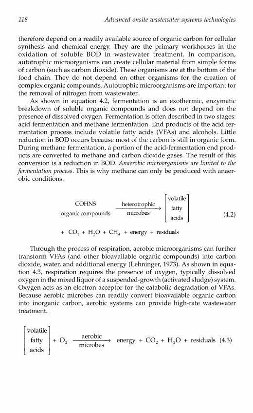
118 Advanced onsite wastewater systems technologies
therefore depend on a readily available source of organic carbon for cellularsynthesis and chemical energy. They are the primary workhorses in theoxidation of soluble BOD in wastewater treatment. In comparison,autotrophic microorganisms can create cellular material from simple formsof carbon (such as carbon dioxide). These organisms are at the bottom of thefood chain. They do not depend on other organisms for the creation ofcomplex organic compounds. Autotrophic microorganisms are important forthe removal of nitrogen from wastewater.
As shown in equation 4.2, fermentation is an exothermic, enzymaticbreakdown of soluble organic compounds and does not depend on thepresence of dissolved oxygen. Fermentation is often described in two stages:acid fermentation and methane fermentation. End products of the acid fer-mentation process include volatile fatty acids (VFAs) and alcohols. Littlereduction in BOD occurs because most of the carbon is still in organic form.During methane fermentation, a portion of the acid-fermentation end prod-ucts are converted to methane and carbon dioxide gases. The result of thisconversion is a reduction in BOD. Anaerobic microorganisms are limited to thefermentation process
. This is why methane can only be produced with anaer-obic conditions.
(4.2)
Through the process of respiration, aerobic microorganisms can furthertransform VFAs (and other bioavailable organic compounds) into carbondioxide, water, and additional energy (Lehninger, 1973). As shown in equa-tion 4.3, respiration requires the presence of oxygen, typically dissolvedoxygen in the mixed liquor of a suspended-growth (activated sludge) system.Oxygen acts as an electron acceptor for the catabolic degradation of VFAs.Because aerobic microbes can readily convert bioavailable organic carboninto inorganic carbon, aerobic systems can provide high-rate wastewatertreatment.
(4.3)
COHNS
organic compounds
heterotrophicmicrobees
volatile
fatty
acids
+
⎯ →⎯⎯⎯⎯⎯⎡
⎣
⎢⎢⎢
⎤
⎦
⎥⎥⎥
CO + H O + CH + energy + residu2 2 4 aals
volatilefattyacids
+ Oaerobic
2
⎡
⎣
⎢⎢⎢
⎤
⎦
⎥⎥⎥ mmicrobes
energy + CO + H O +2 2⎯ →⎯⎯⎯⎯ residuals
3029_book.fm Page 118 Wednesday, November 23, 2005 10:30 AM
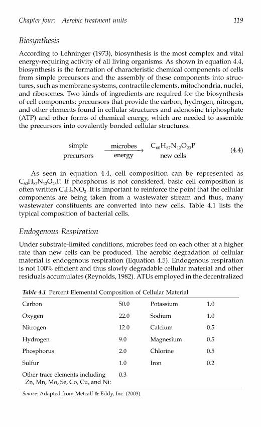
Chapter four: Aerobic treatment units 119
Biosynthesis
According to Lehninger (1973), biosynthesis is the most complex and vitalenergy-requiring activity of all living organisms. As shown in equation 4.4,biosynthesis is the formation of characteristic chemical components of cellsfrom simple precursors and the assembly of these components into struc-tures, such as membrane systems, contractile elements, mitochondria, nuclei,and ribosomes. Two kinds of ingredients are required for the biosynthesisof cell components: precursors that provide the carbon, hydrogen, nitrogen,and other elements found in cellular structures and adenosine triphosphate(ATP) and other forms of chemical energy, which are needed to assemblethe precursors into covalently bonded cellular structures.
(4.4)
As seen in equation 4.4, cell composition can be represented asC
60
H
87
N
12
O
23
P. If phosphorus is not considered, basic cell composition isoften written C
5
H
7
NO
2
. It is important to reinforce the point that the cellularcomponents are being taken from a wastewater stream and thus, manywastewater constituents are converted into new cells. Table 4.1 lists thetypical composition of bacterial cells.
Endogenous Respiration
Under substrate-limited conditions, microbes feed on each other at a higherrate than new cells can be produced. The aerobic degradation of cellularmaterial is endogenous respiration (Equation 4.5). Endogenous respirationis not 100% efficient and thus slowly degradable cellular material and otherresiduals accumulates (Reynolds, 1982). ATUs employed in the decentralized
Table 4.1
Percent Elemental Composition of Cellular Material
Carbon 50.0 Potassium 1.0
Oxygen 22.0 Sodium 1.0
Nitrogen 12.0 Calcium 0.5
Hydrogen 9.0 Magnesium 0.5
Phosphorus 2.0 Chlorine 0.5
Sulfur 1.0 Iron 0.2
Other trace elements including Zn, Mn, Mo, Se, Co, Cu, and Ni:
0.3
Source:
Adapted from Metcalf & Eddy, Inc. (2003).
simpleprecursors
microbesenergy
⎯ →⎯⎯⎯⎯C H N O P
new cells60 87 12 23
3029_book.fm Page 119 Wednesday, November 23, 2005 10:30 AM

120 Advanced onsite wastewater systems technologies
wastewater management industry operate in the endogenous respirationphase. Referred to as extended aeration,
this process provides plenty of aera-tion to ensure that microbes will start feeding on each other once food isconsumed. This effect minimizes the accumulated biomass that must beremoved by the maintenance provider.
(4.5)
Environmental factors
In order to provide high-rate oxidation of organic pollutants, microorgan-isms must be provided with an environment that allows them to thrive.Temperature, pH, dissolved oxygen and other factors affect the natural selec-tion, survival, and growth of microorganisms and their rate of biochemicaloxidation.
Temperature
The rate of bio-oxidation is a function of temperature. Various microbialspecies have optimal temperatures for survival and cell synthesis:
• Psychrophilic microorganisms thrive in a temperature range of -2
°
to 30
°
C (28
°
to 86
°
F). Optimum temperature is 12
°
to 18
°
C (54
°
to64
°
F).• Mesophilic microorganisms thrive in a temperature range of 20
°
to45
°
C (68
°
to 113
°
F). Optimum temperature is 25
°
to 40
°
C (77
°
to104
°
F).• Thermophilic microorganisms thrive in a temperature range of 45
°
to 75
°
C (113
°
to 167
°
F). Optimum temperature is 55
°
to 65
°
C (131
°
to149
°
F).
Overall, as temperature increases, so does microbial activity. Generallyspeaking, decentralized ATUs are buried and the soil acts as a sink for theheat generated by the exothermic activity within the treatment unit. Themicrobial population in a buried ATU consists of a mixture of psychrophilicand mesophilic organisms.
Food-to-microorganism ratio
The food-to-microorganism ratio (F/M) represents the mass of bioavailableorganic compounds (substrate) loaded into the aeration chamber each dayin relation to the mass of microorganisms contained within the aeration
C H N O Pcellular material
+ Oaero60 87 12 23
2bbic
microbesCO + H O + PO +2 2 4⎯ →⎯⎯⎯⎯ NNH + residuals3
3029_book.fm Page 120 Wednesday, November 23, 2005 10:30 AM

Chapter four: Aerobic treatment units 121
chamber. Typically, this ratio is expressed in terms of mass of soluble BODper day per mass of microbes in the treatment unit (Crites and Tchobano-glous, 1998). Microbial populations are dynamic and respond to changes inlife-sustaining parameters. A time lag occurs between sudden changes inorganic loading and changes in the microbial population. However, if allother factors are constant, the population can rapidly increase in responseto increased organic loading. To effectively treat an increased organic load,the hydraulic retention time of the basin must correspond to the timerequired for the population to increase. However, increased organic loadingis often associated with increased hydraulic loading. If a means of flowequalization has not been provided, then effluent will not have the sameresidence time or be exposed to the same concentration of microbes.
Acid concentration
The pH of influent has a significant impact on wastewater treatment. Bene-field and Randall (1985) report that it is possible to treat organic wastewatersover a wide pH range; however, the optimum pH for microbial growth isbetween 6.5 and 7.5. It is interesting to note that bacteria grow best underslightly alkaline conditions. Conversely, algae and fungi grow best underslightly acidic conditions. The response to pH is largely due to changes inenzymatic activity.
Aerobic treatment unit operation
ATUs are high-rate oxidizers of soluble organic and nitrogenous compounds.From a biological perspective, ATUs used for individual homes and decen-tralized systems do not employ any processes that are not currently utilizedin large-scale municipal wastewater treatment plants. The technology uniqueto ATUs is the design and packaging of these systems for small-flow situa-tions. These devices are essentially miniature wastewater treatment plants.In addition to reducing of BOD via aerobic digestion and the conversion ofammonia by nitrification, many commercially available ATUs have addi-tional chambers that promote the removal of nutrients, suspended solids,and pathogens from effluent. Other unique aspects to the design of ATUsare the ease of installation at remote locations and the ease of maintenancefor semiskilled maintenance providers. ATUs installed at home sites andsmall commercial locations must be dependable and maintenance-friendly.
Process description
Primary treated wastewater enters the aeration unit and is mixed with dis-solved oxygen and suspended or attached microbes, or both. Primary treat-ment is provided by a “trash tank,” which is essentially a septic tank that issized for a shorter detention time than a standard septic tank. Aerobicmicrobes convert organic compounds into energy, new cells, and residual
3029_book.fm Page 121 Wednesday, November 23, 2005 10:30 AM

122 Advanced onsite wastewater systems technologies
matter. As the water moves through the clarifier, a portion of the biologicalsolids is separated out of the effluent and retained within the ATU. Thesebiological solids settle back into the aeration chamber, where they serve asseed for new microbial growth. Settled biomass and residuals accumulatein the bottom of the chamber and must be periodically removed.
Because biomass creates an oxygen demand, clarification is an importantpart of generating high-quality effluent. The soluble BOD of effluent is gen-erally below 5 mg/L, but the biomass solids that carry over may producean effluent BOD of 20 mg/L or greater (Benefield and Randall, 1985). ManyATUs have a cone-shaped clarifier to promote separation of the biomass. Asthe cross-sectional area of upflow increases, fluid velocity decreases. Oncethe settling velocity of the biomass is greater than the fluid velocity, thebiomass will no longer move upward (Eikum and Bennett, 1992). Duringperiods of no flow, the biomass will settle back into the aeration chamber.Other ATUs may incorporate inline filters to separate the biomass from theeffluent. Such filters require periodic maintenance to remove the buildup ofsolids.
In the aerobic process, organic nitrogen and ammonia are converted tonitrate. Under anoxic conditions (no molecular oxygen), this nitrate is den-itrified to nitrogen gas. Some ATUs are designed to provide denitrificationas part of their operation. Design modifications include intermittently sup-plying air and recirculating the nitrified wastewater into the anoxic regionswithin the treatment unit.
Typical ATU configurations
Most ATUs operate as intermittent-flow, complete mix tank, constant volumereactors. The flow is intermittent because influent flow is not continuous.The contents of the aeration chamber are thoroughly mixed to maximizecontact with dissolved oxygen, microbes, and wastewater. Effluent movesout of the aeration chamber and into a clarifier. The rate of discharge isdirectly related to the rate of inflow. The exception to this generalization issequencing batch reactors. As described later in this section, this treatmentdevice operates in batch mode.
Extended aeration
Most commercially available ATUs operate as extended aeration units.Extended aeration is characterized by long-term aeration, long detentiontimes, low F/M ratio, and low biomass accumulation. As shown in Figure4.1, by providing plenty of dissolved oxygen and minimal soluble organicmatter, the microbes will be forced into the endogenous phase of growthand will readily consume bioavailable organic carbon, including biomass.The goal is to balance the mass of new cells synthesized each day with themass of cells endogenously biochemically degraded each day. The AmericanSociety of Civil Engineers (ASCE, 1977) suggests that, for a treatment unit
3029_book.fm Page 122 Wednesday, November 23, 2005 10:30 AM

Chapter four: Aerobic treatment units 123
to operate in extended aeration, 2000 cubic ft of air should be injected in thewater per pound of BOD
5
removed.As shown in Figure 4.1, kinetics of aerobic digestion, as substrate
increases, biomass increases. These curves represent a batch-style applicationof substrate, in which biomass concentration changes in response to changesin substrate concentration. Intermittent-flow, complete mix systems onlyoperate over a small range on these curves because the concentration ofsubstrate tends to be relatively constant.
Suspended-growth bioreactors
As shown in Figure 4.2, suspended-growth ATUs are scaled-down activatedsludge plants. Activated sludge is a heterogeneous microbial culture com-posed mostly of bacteria, protozoa, rotifers, and fungi. The bacteria areresponsible for assimilating most of the organic material, whereas the pro-tozoa and rotifers (serving as predators) are important in removing thedispersed bacteria that would otherwise escape in ATU effluent (Benefieldand Randall, 1985). The biomass is thoroughly mixed with biodegradableorganic compounds. Individual organisms clump together (flocculate) toform an active mass of microbes called biological floc
(Davis and Cornwell,
Figure 4.1
Kinetics of aerobic digestion.
Figure 4.2
Schematic diagram of a suspended-growth ATU.
LagPhase
GrowthPhase
StationaryPhase
EndogenousPhase
Time
Biomass Concentration
Con
cent
ratio
n Substrate Concentration
ChamberSettling
BaffleBaffle
SludgeReturn
EffluentInfluent(from Primary Tank)
Maintenance Access
AerationDevice
(clarifier)
Suspended-GrowthChamber
3029_book.fm Page 123 Wednesday, November 23, 2005 10:30 AM

124 Advanced onsite wastewater systems technologies
1991). This slurry of biological floc and wastewater is called mixed liquor
(Reynolds, 1982). The concentration of microorganisms in mixed liquor ismeasured as mg/L of mixed liquor volatile suspended solids (MLVSS). Thatis the volatile
suspended solids concentration in the aeration
basin contents.Reynolds (1982) wrote that the term activated
is used to describe thereactive nature of biological solids. As wastewater enters the aeration cham-ber, suspended floc adsorbs organic solids and absorbs soluble organic com-pounds. Through enzymatic activity, the organic solids are solubilized. Oncein solution, the soluble organics are oxidized by biochemical oxidation. Atthe inflow of the ATU, the capacity of the biological solids to adsorb andabsorb substrate is rapidly filled. As the mixture moves into the clarificationzone, the biological solids (or "activated" sludge) are re-activated as theoxidation process proceeds. Near the downstream end of the ATU, the bio-logical solids are substrate limited and are therefore highly reactive to theremaining suspended and dissolved organic solids. The extended aerationprocess has been shown to run properly at a F/M ratio of 0.042 to 0.153 Lbof BOD per Lb of MLVSS. Functionally, MLVSS should not fall below 2500mg/L or exceed 6000 mg/L. Organic loading is typically about 15 Lb BODper 1000 cubic feet of volume per day.
Attached-growth bioreactors
Another broad category of ATUs is attached-growth systems. Often calledfixed-film reactors,
these systems contain an inert medium for microbial attach-ment (Figure 4.3). As wastewater flows through or across the media, fine,suspended, colloidal and dissolved organic solids are absorbed by the bio-logical film. Wastewater and dissolved oxygen are brought in contact withthe attached microorganisms by either pumping the liquid past the mediaor by moving the media through the liquid.
Coupled contact aeration
Treatment units are available that combine attached growth in the same basinas suspended growth. Referred to as coupled-contact aeration,
the combinationof attached-growth and suspended-growth processes enhances the perfor-mance and capacity of aeration units (U.S. EPA, 2002). This dual-systemapproach provides a higher degree of microbial population stability, andlower effluent suspended solids and BOD. Attached-growth areas are sub-merged and large channels are provided for turbulent water to flow overthe surfaces. These large channels allow suspended-growth microbes toflourish. Aeration is provided by directly injecting air or by circulating thewater to the air-liquid interface. Excessive attached growth sloughs off andsettles to the bottom of the chamber. These solids accumulate and must beremoved as part of periodic maintenance procedures.
3029_book.fm Page 124 Wednesday, November 23, 2005 10:30 AM

Chapter four: Aerobic treatment units 125
Rotating biological contactor
Rotating biological contactors (RBCs) combine suspended-growth andattached-growth bioprocesses. In RBCs, a series of closely spaced circulardisks are mounted on a common shaft and are slowly rotated (Photo 4.1).The shaft is located either just above or just below the water surface. Thislocation allows the surface of the disks to be exposed to both air and waste-water while rotating. A typical disk is made of an inert material such aspolystyrene or polyvinyl chloride. A fixed-film biological growth attaches tothe disks and, when submerged, the organisms are exposed to food. Inrotation, the reactor carries the fixed film into the air, where it absorbsoxygen. Excess dissolved oxygen mixes with the bulk liquid as the contactorsurface moves back through the wastewater (ASCE, 1977). As the thicknessof attached biomass on the disk increases, some of excess biomass is shearedoff the disk. This biomass is kept in suspension by the rotation of the disks.Ultimately, the flow of wastewater carries the solids out of the reactor cham-ber and into the clarifier.
Figure 4.3
Coupled contact aeration system.
Photo 4.1
Rotating biological contactor.
ChamberSettling
BaffleBaffle
SludgeReturn
EffluentInfluent(from Primary Tank)
Maintenance AccessAerationDevice
(clarifier)
3029_book.fm Page 125 Wednesday, November 23, 2005 10:30 AM

126 Advanced onsite wastewater systems technologies
Generally, about 35 to 45% of a disk's surface is submerged in a RBCthat is designed with the shaft just above the water surface. A system thathas the shaft submerged in the water produces about 70% to 90% submer-gence (Crites and Tchobanoglous, 1998). A higher degree of organic removaland nitrification may be obtained by arranging sets of disks (or other inertmedia) in series, because each subsequent stage receives an influent with alower organic concentration than the previous stage. The tank constructionusually consists of reinforced concrete or steel and is enclosed to maintainenvironmental controls and to confine any nuisance odors. RBCs can bescaled down for single-family homes or scaled up to provide secondarytreatment at municipal wastewater treatment plants (Metcalf & Eddy, Inc.,2003).
Sequencing batch reactor systems or periodic processes
In sequencing batch reactor (SBR) systems, flow equalization, aeration, clar-ification, and biomass wasting processes are carried out sequentially in thesame tank (U.S. EPA, 1986, 1992). Because most SBRs require the system tobe closed to influent during the treatment cycles, two reactors operating inparallel are required in order to maintain continuous flow. However, withnew inlet designs, single-tank reactors can be used to maintain continuousflow. The SBR process can provide flow equalization and tends to modulatethe quantity and strength of wastewater inflow.
SBR process description
One cycle of SBR operation has five basic modes:
• Fill
— Raw wastewater that has been through primary treatment isadded to the reactor. During this phase, aeration may or may not besupplied to provide alternating periods of high and low dissolvedoxygen. This mode may occupy 25% of the total cycle time.
• React —
Aeration is provided in an effort to obtain rapid biodegra-dation of organic and nitrogenous compounds. This mode typicallyconsumes about 35% of the total cycle time.
• Settle —
Aeration is shut off to allow the wastewater to becomeanoxic (for denitrification) and to allow for quiescent conditions thatpermit very effective liquid-solid separation. Clarification usuallytakes about 20% of the overall cycle time.
• Draw (also called “decanting”)—
Clarified supernatant is removed.Decanting is accomplished using adjustable weirs, floating weirs, andsubmersible pumps. Excess biosolids must periodically be removed.Decanting generally takes about 15% of the total cycle time.
• Idle —
Time is allowed for the first reactor to complete its full cycle,and then switch the flow into the second reactor for parallel operation.
This cycle is illustrated in Figure 4.4.
3029_book.fm Page 126 Wednesday, November 23, 2005 10:30 AM

Chapter four: Aerobic treatment units 127
An important element in the SBR process is that a tank is never com-pletely emptied; rather, a portion of settled solids are left to seed the nextcycle (Henry and Heinke, 1996). This allows the establishment of a popula-tion of organisms uniquely suited to treating the wastewater. By subjectingthe organisms to periods of high and low oxygen levels, and to high andlow food availability, the population of organisms becomes very efficient attreating the particular wastewater (Henry and Heinke, 1996).
Nitrogen removal in SBRs
During aeration, organic and ammonia nitrogen present in the wastewaterare converted to nitrate. When aeration is suspended and the remainingdissolved oxygen is consumed, denitrifying bacteria strip the oxygen out ofthe nitrate molecule, converting nitrate to nitrogen gas (denitrification).While other ATUs can be designed to provide denitrification, the SBRsequence can provide denitrification conditions without adding additionalunit processes.
Figure 4.4
Sequencing Batch Reactor (SBR) cycles.
Sequence One: FillAdd Substrate
Aeration: Cycled On-OffPercent of Cycle Time: Approximately 25%
Sequence Two: ReactBiochemical Oxidation of Organic
Aeration: On-Off to promote DenitrificationPercent of Cycle Time: Approximately 35%
Sequence Three: SettleClarification of Suspended Solids & Biomass
Aeration: OffPercent of Cycle Time: Approximately 20%
Sequence Four: DrawRemove Clarified Effluent
Aeration: OffPercent of Cycle Time: Approximately 15%
Sequence Five: IdleWaste Sludge
Aeration: Cycled On-OffPercent of Cycle Time: Approximately 5%
3029_book.fm Page 127 Wednesday, November 23, 2005 10:30 AM

128 Advanced onsite wastewater systems technologies
Typical applications of SBRs
With the development of reliable automatic control systems, SBR packageplants have become competitive with more traditional ATUs. The process isflexible and efficient and can accommodate large fluctuations in hydraulicand organic loads. The process is particularly applicable to small communi-ties, because of easy installation, simple operation, lower maintenance, andhigher energy efficiency (U.S. EPA, 1992).
Other Process ConsiderationsOxygen transfer
Large quantities of oxygen must be provided to maintain aerobic conditions.If influent to the ATU has an ultimate BOD of 100 mg/L, then 100 mg ofdissolved oxygen per liter of influent must be provided to satisfy the oxygendemand. The primary function of the aeration system is to transfer oxygento the liquid at such a rate that dissolved oxygen never becomes a limitingfactor. Oxygen is only slightly soluble in water. Natural aeration cannot meetthe demand of this high-rate unit process and, therefore, oxygen transfermust be engineered into the treatment unit in order to maintain a minimumresidual of 1 mg of dissolved oxygen per liter of water.
The passage of oxygen from the gas phase (air) into the liquid (waste-water) phase is absorption. The driving force of oxygen transfer is the con-centration gradient between the atmosphere and the bulk liquid. This gra-dient is created when there is a difference in the equilibrium concentrationin the two phases. Thus, the force required to obtain equilibrium drives thetransfer of atmospheric oxygen into the water. The saturated concentrationof dissolved oxygen changes with temperature, barometric pressure, andsalinity and with the concentration of water impurities. Designers of ATUsmust maximize the contact interface (surface area) between the gas andliquid phases in order to maximize the opportunity for oxygen transfer. Inother words, systems must be designed so that the concentration gradientbetween the gas-liquid interfaces is high and, therefore, the rate of transferwill also be high.
Aeration units are evaluated on the mass of oxygen transferred per unitof air introduced to the water. This is known as an efficiency rating.
The goalis to maximize the mass of oxygen transferred per unit of energy consumedby the device. The most common method of maximizing energy efficiencyis to combine mixing with aeration. Turbulent mixing is required to maxi-mize the opportunity for microbes to come in contact with both solubleorganic compounds and dissolved oxygen. If steady-state conditions can bemaintained, the rate of oxygen transfer is equal to the rate of consumptionby the microorganisms. Dissolved oxygen in the mixed liquor should bemaintained at 1 to 3 mg/L. For residential-strength wastewater, Metcalf &Eddy, Inc. (2003) reports that 2 to 7 g/day of dissolved oxygen is needed foreach gram of MLVSS.
3029_book.fm Page 128 Wednesday, November 23, 2005 10:30 AM

Chapter four: Aerobic treatment units 129
For most ATUs, the actual oxygen mass transfer efficiency is proprietaryinformation. Manufacturers market specific ATU models based on organicand hydraulic loading. For a given unit, the aeration device is rated toprovide sufficient dissolved oxygen for the given range of input oxygendemands (organic loading).
Basically, manufacturers of ATUs utilize two types of aerators: diffusedair systems and mechanical aeration systems. Diffused air systems use sub-merged devices (spargers) to inject air into the bulk liquid. As shown inFigure 4.5, air injected below the surface has continuous contact with theliquid as it rises to the surface. The smaller the bubble, the greater the oxygentransfer rate. Additionally, bubbles formed deep within the chamber havemore hydrostatic pressure to drive the oxygen transfer and more time-of-con-tact with the air-water interface. Another method of creating small bubblesinvolves porous ceramic diffusers. The small, interconnected passagewaysinside the ceramic matrix create a tremendous loss of air pressure and manypoints of outflow. This combination produces streams of small bubbles overthe surface of the ceramic diffuser. A second method of injecting air is toprecisely drill orifices into pipes and plates. Many large-scale aerobic digest-ers use jet aerators. Streams of air serve to transfer oxygen and to providevigorous mixing of basin contents.
A third type of diffused aerator is an aspirated mixer. As shown in Figure4.6, a mixing-propeller attaches to a hollow shaft that vents to the atmo-sphere. This propeller is located near the bottom of the aeration chamber.As the shaft spins, a venturi effect creates a vacuum down the shaft andinjects air into the water. The mixing devices must balance the need for
Figure 4.5
Aeration in an ATU by air spargers.
Figure 4.6
Aspirated mixer for aeration of an ATU.
ChamberSettlingChamber
Aeration
Air Sparger
BaffleBaffle
SludgeReturn
EffluentInfluent
Blower
(from Primary Tank)
Maintenance Access
ChamberSettling
BaffleBaffle
SludgeReturn
EffluentInfluent(from Primary Tank)
Maintenance Access
Aeration&MixingChamber
Aspirated Mixer
Hollow Shaft
Motor
3029_book.fm Page 129 Wednesday, November 23, 2005 10:30 AM

130 Advanced onsite wastewater systems technologies
agitation while minimizing the shearing of floc. If shear is excessive, poorsettling conditions in the clarifier can result.
Several ATU manufacturers employ a cycled-aeration approach. Cyclingthe aeration system provides some energy savings and promotes nitrogenremoval (temporary anoxic conditions). Care must be taken, however,because this technique can produce a poor settling biomass due to gasflotation and nonflocculating microbes.
ATU influent
Influent to an aerobic treatment chamber typically passes through primarytreatment, provided by either a septic tank or some other type of primarytank. ATUs that can receive raw wastewater directly from a house and donot require primary tanks are also available. When used, primary tanks canprovide separation of easily settleable and floatable solids before the influententers the ATU. A large portion of these solids are likely nondegradable orslowly degradable. Manufacturers of ATUs provide guidance regarding therequired size of a primary tank for their aerobic treatment devices. Primarytanks also provide an element of dilution that minimizes the effects of chem-ical shocks on the microbial population in the ATUs. Medications, such asantibiotics and chemotherapy drugs, are highly toxic to the microbial pop-ulation. Most manufacturers list products that should not be added to thewastewater stream. In some manufacturers’ literature, this list includes watersoftener brine backwash.
Hydraulic and organic loading
The specifications of an ATU are based on both hydraulic and organic load-ing. Hydraulic loading is the rate that water passes through the device; itprovides information about the length of time that wastewater will beexposed to microbes. For example, if a basin has a volume of 1000 gal andthe wastewater flow is 500 gal per day (gpd), the hydraulic detention timeis 2 days. Organic loading refers to the food (incoming colloidal and solubleBOD) as compared to the microbial population available to consume thefood (F/M ratio). Organic load is typically expressed in pounds per day.Used in this way, load
is the product of flow and concentration, as indicatedin Equation 4-6. If there is more food than microbes, the effluent quality willbe poor. If there are more microbes than food, then the effluent quality willbe high. As previously mentioned, the population of microbes is dynamicin an ATU.
Load (Lb per day) = Flow (gpd)
×
concentration (mg/L)
×
8.34
×
10
–6
(4.6)
If a system has been upset due to heavy laundry water loads that arelow in soluble BOD, the microbial population may be reduced because of a
3029_book.fm Page 130 Wednesday, November 23, 2005 10:30 AM

Chapter four: Aerobic treatment units 131
lack of food. Additionally, wash-out of microbes can occur if hydraulicloading is greater than the designed outflow rate of the clarifier. When thenext heavy dose of organic material enters the tank, the microbial populationmay be insufficient to complete the digestion of BOD during the hydraulicdetention period. This phenomenon has been observed in seasonal applica-tions, such as baseball fields and state parks. Furthermore, if an ATU isdesigned for a subdivision at ultimate build out, the F/M may not be ade-quate when only a few homes have been built in the subdivision during theearly stages of development.
Flow equalization
ATUs are designed to work within a range of hydraulic and organic loads.Variations in flow rates and constituent concentrations that are outside ofthe design specifications seriously complicate the treatment process. Munic-ipal plants have the advantage of serving large populations, which tend tobalance their daily organic and hydraulic loading rates. However, duringstorm events, municipal plants must deal with tremendous inflow and infil-tration problems. Municipal plants commonly use offline equalization basinsor bypass aerobic treatments in order to prevent wash-out of microbes.Likewise, residential ATUs must be designed to handle days with high flowsand still be able to provide sufficient biochemical treatment to dischargedwastewater. Ideally, flow equalization would dampen the variations, so thatthere would be a constant or near-constant flow rate into the ATU. Equal-ization can be achieved with storage, float switches, pumps, and timers.Generally, additional storage in the primary tank is the most cost-effectivemethod to accomplish flow equalization because tankage is usually the leastcostly portion of the overall expenses (Bounds, 2003). Most ATUs are notdesigned to provide flow equalization and, therefore, equalization must beprovided just prior to the ATU.
Nitrogen and phosphorus in wastewaterThe presence of nitrogen in wastewater results from the degradation ofproteinaceous matter in feces and from urea, the chief constituent in urine.Nitrogenous compounds undergo various biotransformations in response tothe presence or absence of dissolved oxygen. ATU influent, having just exitedfrom a septic tank or other primary treatment system, contains nitrogen inorganic or reduced-ammonium ion form. In the aerobic environment of anATU, most of the ammonium will be oxidized to nitrate (NO3), which is themost highly oxidized form of nitrogen. While in the ATU, a fraction ofnitrogen may be removed by sedimentation, volatilization, and denitrifica-tion. Unless process modifications are made to the ATU, no reliance on netnitrogen removal can be expected. Nitrogen removal is highly dependent onspecific performance of individual ATUs to create denitrification conditions.
3029_book.fm Page 131 Wednesday, November 23, 2005 10:30 AM

132 Advanced onsite wastewater systems technologies
Because phosphorus is often a limiting nutrient in natural ecosystems,eutrophication can occur when excess phosphorus is discharged to a surfacewater body. In wastewater, phosphorus can be bound in organic compoundsor can be in soluble phosphate form (PO4). Typical phosphorus concentra-tions in septic tank effluent range between 6 and 12 mg/L. Bacteria assimilatea small portion of the orthophosphate during their growth process. Concep-tually, this amount of phosphorous could be removed by sedimentation.Because residential ATUs operate in the endogenous phase, very little sludgewastage (and thus very little phosphorus removal) occurs. When a higherdegree of phosphorus removal is needed, a more advanced wastewatertreatment system, such as chemical precipitation or a wastewater treatmentplant designed for biological nutrient removal, would be required.
Operational issuesStart up
Start up involves the establishment of a sufficient population of microbeswithin the ATU to digest the soluble organic and nitrogenous componentsof influent. In most applications, a sufficient population of microbes enterthe ATU with the wastewater to start the process. If needed, one method ofinoculating the system is to add a few gallons of mixed liquor from anoperational ATU such as a municipal wastewater treatment plant. While thebiomass concentration is increasing, microbes tend to be dispersed and donot form floc that will settle in the clarifier. Until the biomass becomes moreflocculated and can settle more readily, there is a greater potential for solidscarry over, especially with high hydraulic loads. If solids build up in theclarifier, gas forms in the biosolids (as a result of anaerobic conditions withinthe solids) and cause solids to rise to the surface and form a scum layer. Thequality of activated sludge offers a good measure of how well the processis proceeding. Generally, good quality activated sludge has a golden-browncolor and an earthy smell if kept aerated. Microscopic examination alsoreveals a relatively varied population, with a healthy population of rotifersand other motile organisms.
Typical problems
Sludge bulking is a phenomenon that develops in the aeration tank when agrowth of filamentous bacteria (primarily Sphaerotilus) attaches to the flocparticles and impedes settling (Crites and Tchobanoglous, 1998). Such micro-organisms can tolerate large changes in dissolved oxygen and nutrients, asituation that frequently occurs in small ATUs. These conditions cause acarryover of solids into the effluent. This phenomenon is particularly trou-blesome to smaller plants that may have considerable fluctuation in organicloading and lack of technical support.
3029_book.fm Page 132 Wednesday, November 23, 2005 10:30 AM

Chapter four: Aerobic treatment units 133
When excessive growth of Nocardia (a hydrophobic bacterium) occurs,foaming and frothing on the liquid surface in the aeration chamber (and theclarifier) may result. The problem is exacerbated by the fact that the bafflesin the clarifier trap the foam and foster more growth (Crites and Tchobano-glous, 1998). Some ATU manufacturers provide froth spray pumps. The frothspray reduces the surface tension of the water and breaks down the froth(Ohio EPA, 2000).
Biomass (sludge) wastage
Although ATUs use the extended aeration process, endogenous degradationcannot completely prevent accumulation of old biomass. Biomass and non-biodegradable solids commonly accumulate in a low areas of ATUs and,periodically, a maintenance provider must remove a portion of these solids.During removal, it is important to leave some of the solids in the aerobicchamber to serve as seed to repopulate the biological floc.
Performance certificationThe National Sanitation Foundation (NSF International) and the AmericanNational Standards Institute (ANSI) publish a standardized procedure forindependent evaluators to certify the performance and reliability of aerationunits. NSF/ANSI Standard 40-2000, "Residential Wastewater Treatment Sys-tems," establishes minimum materials, design and construction, and perfor-mance requirements for residential wastewater treatment systems havingsingle, defined discharge points and treatment capacities between 400 and1500 gpd.
Mechanical evaluation
Design and construction requirements of the NSF/ANSI Standard ensurethat structural integrity is maintained when a system is subjected to earthand hydrostatic pressures. An in situ visual evaluation of the structuralelements is performed during and after the performance testing period. Thesystem is tested to ensure that it is watertight (i.e., no infiltration of ground-water or exfiltration of wastewater occurs). Water tightness is evaluated byfilling the tank with tap water to the level of the high-level alarm. This levelis then monitored for 24 hours.
All ATUs have moving parts. These parts operate in very corrosiveenvironments and therefore require periodic maintenance and replacement.During the certification procedure, all mechanical components are evaluatedto determine the frequency of required maintenance and the ease by whichmaintenance can be performed by a service provider. Inspections are con-ducted to ensure that all electrical components are protected by safetydevices that meet or exceed ANSI/National Fire Protection Association(NFPA) Standard 70. ATUs must have mechanisms or processes capable of
3029_book.fm Page 133 Wednesday, November 23, 2005 10:30 AM

134 Advanced onsite wastewater systems technologies
detecting failures of electrical and mechanical components that are criticalto the treatment processes and detecting high water conditions. These mech-anisms must be capable of delivering visible and audible signals to notifyowners when electrical, mechanical, or hydraulic malfunctions occur.
All units must have ground-level access ports for visual inspection,periodic cleaning, replacement of components, removal of residuals, andsampling. Access to ports must be protected against unauthorized intrusionvia padlocks, covers requiring the use of special tools, or covers weighing aminimum 65 Lb (29 kg).
Performance evaluation
NSF performance testing and evaluation of a specific type or model oftreatment system is conducted for 26 consecutive weeks, with 16 weeksof design loading followed by 7.5 weeks of stress loading, and another2.5 weeks of design loading. Design loading consists of operating 7 daysper week with a wastewater volume equivalent to the daily hydrauliccapacity of the unit. The 30-day average carbonaceous BOD5 (CBOD5) andtotal suspended solids (TSS) concentrations of wastewater entering thesystem should range between 100 and 300 mg/L and 100 and 350 mg/L,respectively. Stress loading is designed to simulate four nondesign con-ditions: laundry day, working parents, power or equipment failure, andvacation.
Performance testing and evaluation are conducted during 96 data days,with no interruptions for routine service or maintenance. Unless otherwisespecified, all sample-collection and analysis methods must be in accordancewith the current edition of the American Public Health Association's Stan-dard Methods for the Examination of Water and Wastewater. During periodsof design loading, daily composite effluent samples are collected and ana-lyzed 5 days per week. During stress-loading conditions, influent and efflu-ent 24-hr composite samples are collected on the day each stress conditionis initiated. Afterwards, samples are taken to monitor the recovery of thetreatment unit. Twenty-four hours after the completion of the wash-day,working-parent, and vacation stresses, influent and effluent 24-hr compositesamples are collected for 6 consecutive days. Forty-eight hours after thecompletion of the power/equipment failure stress, influent and effluent24-hr composite samples are collected for 5 consecutive days.
Residential wastewater treatment systems are classified as either ClassI or Class II, according to the chemical, biological, and physical charac-teristics of their effluents. A Class I certification indicates performance toEPA Secondary Treatment Guidelines for three parameters: CBOD5, solids,and pH (U.S. EPA, 1996). During the first calendar month of performancetesting and evaluation, a unit is allowed to exceed 1.4 times the effluentlimits for CBOD5 and TSS sample concentrations without losing Class Istatus. A system can be designated Class II if 10% (or less) of its effluentCBOD5 and TSS sample concentrations are greater than 60 mg/L and 100
3029_book.fm Page 134 Wednesday, November 23, 2005 10:30 AM

Chapter four: Aerobic treatment units 135
mg/L, respectively. Table 4.2 provides the criteria for Class I and Class IIperformance standards.
As shown in Table 4.2, the performance bases of NSF/ANSI Standard40 are organic carbon and suspended solids in the effluent. However, thereis increased interest in evaluating treatment units for their capacity to removenitrogen, phosphorus, and pathogens. Standard 40 provides procedures forevaluation of the removal of these constituents. However, specific perfor-mance of the removal of these constituents is not required in order to receivecertification (Converse, 2001). The primary function of saturated ATUs is thedigestion of soluble and colloidal organic compounds and removal of solids.Additional unit processes are added to the treatment train to provide deni-trification, phosphorus removal, and disinfection.
ReferencesAmerican Society of Civil Engineers. 1977. Wastewater Treatment Plant Design, Manual
of Practice No. 36. Lancaster Press, Lancaster, PA.Benefield, L.D. and C.W. Randall. 1985 . Biological Process Design for Wastewater Treat-
ment. Ibis Publishing, Charlottesville, Virginia.Bounds, T. 2003. Personal communication. Orenco Systems, Inc. May 24.Converse, 2001. Aeration treatment of onsite domestic wastewater, aerobic units and
packed bed filters. Small Scale Waste Management Project, University ofWisconsin, Madison, www.wisc.edu/sswmp Publication List.
Crites, R., and G. Tchobanoglous. Small and Decentralized Wastewater ManagementSystems. Boston: WCB/McGraw-Hill Companies, Inc., 1998.
Davis, M.L. and D.A. Cornwell. 1991. Introduction to Environmental Engineering.McGraw-Hill, New York.
Dinges, R. 1982. Natural Systems for Water Pollution Control. Van Nostrand Reinhold,New York.
Table 4.2 NSF/ANSI Standard Number 40-2000 Performance Classifications
Class I
Parameter 30 day average shall not
exceed 7 day average shall not
exceed CBOD5 25 mg/L 40 mg/LTSS 30 mg/L 45 mg/L
Color Individual samples shall be less than 15 NTU unitsThreshold odor NonoffensiveOily film None visible other than air bubbles Foam NonepH The individual effluent samples shall be between 6.0 and 9.0
Class IINot more than 10% of the effluent BOD5 values shall exceed 60 mg/L and not
more than 10% of the effluent TSS values shall exceed 100 mg/L.
3029_book.fm Page 135 Wednesday, November 23, 2005 10:30 AM

136 Advanced onsite wastewater systems technologies
Eikum, A. and T. Bennett. 1992. New Norwegian technology for treatment of smallflows. Proceedings of the Seventh Northwest On-site Wastewater TreatmentShort Course and Equipment Exhibition. University of Washington, Seattle,WA .
Henry, J.G. and G.W. Heinke. 1996. Environmental Science and Engineering, SecondEdition. Prentice Hall, Upper Saddle River, N.J.
Lehninger, A.L. 1973. Bioenergetics, Second Edition. W.A. Benjamin, Inc. Menlo Park,California.
Martin, E.J. and E.T. Martin. 1991. Technologies for Small Water and Wastewater Systems.Van Nostrand Reinhold, New York.
Metcalf & Eddy, Inc. 2003. Wastewater Engineering: Treatment and Reuse, Fourth Edition.McGraw-Hill, Boston.
Ohio Environmental Protection Agency. 2000. Guide for owners of package extendedaeration sewage treatment plants: Operation and maintenance. State of OhioEPA, Division of Surface Water.
Reynolds, T.D. 1982. Unit Operations and Processes in Environmental Engineering. PWSPublishing Co., Boston.
U.S. Environmental Protection Agency. 1986. Summary Report: Sequencing BatchReactors. Office of Water, Washington, D.C., EPA 625886011.
U.S. Environmental Protection Agency. 1992. Summary Report: Small CommunityWater and Wastewater Treatment. Office of Water, Washington, D.C., EPA/625/R-92/010.
U.S. Environmental Protection Agency. 1996. Permit Writers' Manual. Office of Water,Washington, D.C., EPA-833-B-96-003.
U.S. Environmental Protection Agency (2002). Decentralized Systems TechnologyFact Sheet — Aerobic Treatment. Office of Water, Washington, D.C., EPA832-F-00-031.
U.S. Environmental Protection Agency. 2002. Onsite Wastewater Treatment SystemsManual. Office of Water, Washington, D.C., EPA/625/R-00/008.
3029_book.fm Page 136 Wednesday, November 23, 2005 10:30 AM

137
chapter five
Effluent dispersal and recycling systems
Introduction
All onsite wastewater treatment systems need a mechanism for treated efflu-ent to be dispersed and returned to the hydrologic cycle. Subsurface dis-persal (nonpoint source discharge) is the primary mechanism used for releas-ing effluent from onsite treatment systems. For most of the 20th century,onsite wastewater options were limited to only septic systems, so the choicefor wastewater management was either sewer or septic. One of the unin-tended adverse impacts of having limited onsite wastewater choices is deval-uation, or even condemnation, of tracks of land for development whentraditional municipal sewer systems are not accessible and soil and siteconditions do not meet the regulatory requirements for septic systems. It iswidely believed that the rules governing the operation of septic systems areused as de facto zoning tools, mainly because if land is deemed unsuitablefor installing a septic system (i.e., no perc), then no one can build a home orany other structure on it that has potential to generate wastewater.
Research conducted and field experience obtained over the past severaldecades indicate that soil and site conditions necessary for treatment andultimate dispersal of septic tank effluent are not necessary for the treatmentand ultimate dispersal of secondary or better quality effluent. Hence, weneed to look at soil and site conditions in a totally different manner whenadvanced onsite wastewater systems are considered and soil and plant sys-tems are used mainly for “polishing” secondary or better quality effluentrather than for reduction of organic waste load. This is the concept mentionedin Chapter 1 in which soil is not required to remove biological oxygendemand (BOD) or total suspended solids (TSS) and does not serve as amedium for mineralization of nitrogen from organic to inorganic forms.Instead, those functions are performed by an advanced treatment system forwhich the conditions and the material of construction can be controlled,leaving soil to be used for what soil is best for — recycling residual nutrientsand polishing the microbiological quality of effluent.
3029_book.fm Page 137 Wednesday, November 23, 2005 10:30 AM

138 Advanced onsite wastewater systems technologies
Alternatives to conventional septic systems are needed in areas wheresoil and site conditions are not suitable for treating septic tank effluent orwhen use of septic systems is not cost effective or not desired, or wheredesired lot density cannot be achieved by using traditional septic systems.Such systems can also be used for rejuvenating septic tank effluent drainfields that are failing due to age and accumulated biomat. Introduction ofaerobic effluent into an old drain field breaks down the biomat and allowsthe assimilation of aerobic effluent into the subsurface environment, thus insome cases, offering an effective and efficient repair option for old septicsystems.
Dispersal of advanced secondary effluent
Aerobic treatment of wastewater to secondary or better quality effluentshould be a key component of any permanent managed onsite wastewaterinfrastructure. Subsurface dispersal of secondary effluent can be achieved inan environmentally sound manner on any buildable site that is currentlyviewed as unsuitable for a septic system, as long as adequate land area isavailable for hydraulic assimilation of the secondary or better quality effluentand reduction in nutrient or bacteriological contaminant load.
Because a secondary treatment system reduces organic waste load (typ-ically measured as BOD
5
; TSS; and fat, oils and grease [FOG]) prior tointroducing the effluent to the soil dispersal system, performance of aneffluent dispersal system for secondary or better quality effluent is notinfluenced by biomat formation. In traditional septic systems, the formationof a biomat in the drain field is considered an important part of the treatmentfor removal and reduction of bacteriological contaminants. Therefore, aquestion typically arises among regulators about what happens to thosecontaminants when a biomat is not formed in the dispersal systems thatreceive secondary or better quality effluent. Dispersal of aerobic effluentinto a subsurface soil environment allows the soil to retain aerobic condi-tions (unlike the dispersal of septic tank effluent) and thus enhancesremoval (neutralization) of bacteriological contaminants even without theformation of a biomat. Whenever necessary, aerobically treated effluent canbe disinfected using a variety of advanced onsite disinfection technologies,such as ultraviolet or ozone disinfection systems. When chlorination sys-tems are used, effluent should be dechlorinated prior to subsurface dispersalmainly to prevent any adverse impact of the residual chlorine on soil micro-organisms.
Effluent dispersal technologies
Technologies available for dispersal of secondary or better quality effluentcan be grouped as follows:
3029_book.fm Page 138 Wednesday, November 23, 2005 10:30 AM

Chapter five: Effluent dispersal and recycling systems 139
• trenches or beds filled with gravel or other media (gravity fed orpressure dosed)
• gravelless trenches or beds with chamber systems (gravity fed orpressure dosed)
• at-grade or above-grade (shallow trench, filter bed, mound, cappingfill, etc.)
• drip dispersal (subsurface or surface)• spray dispersal (above ground)• minimum or zero discharge (evapotranspiration or greenhouse)• point source discharge into surface water or on the ground• existing onsite dispersal systems after removal of accumulated waste-
water from them.
Photos 5.1 through 5.10 show various projects that use advanced effluentdispersal systems. Information on many other projects that use such dis-persal systems is available on our web site. Designing, sizing, and layout ofthese types of effluent dispersal systems can be done using common senseunderstanding of soil and site conditions and the owners’ requirements.
Adequately treated effluent can be safely released into the environmentusing any of the above effluent management systems, including existingonsite disposal systems (such as cesspools, trenches, seepage pits, infiltrationgalleries, or beds) that are failing due to excessive build up of a biomat.Highly treated effluent can also be used for flushing toilets or other nonpo-table applications prior to release into the environment, thereby reducingthe net amount of liquid discharge.
Since septic systems depend mainly on soil for the treatment of primaryeffluent, soil evaluation has been an integral part of the onsite wastewaterbusiness. However, with the availability of a variety of treatment systems,we no longer need to depend on soil for treating septic tank effluent. Theinstallation of small, shallow or deep trenches, filter beds, drip, spray, orminimum or zero discharge systems for adequately treated effluent can beachieved on almost any site where adequate square footage of space isavailable. Performance of such dispersal systems does not depend on type,depth, or color of soil present at the site. In the 21st century, emphasis needsto be put on the use of appropriate onsite treatment and dispersal systemsand on the permanent operation and maintenance of those systems ratherthan on the acceptance or rejection of a lot for an onsite system based onsoil evaluation and soil criteria.
With the availability of pre-engineered and prepackaged treatment andeffluent management systems in the market today, engineers now have morethan 500 different ways of developing onsite solutions for wastewater sys-tems. Soil and site characteristics as well as environmental sensitivity typi-cally determine which onsite system may be used for a given project. How-ever, a designer may decide to standardize onsite wastewater solutions usinga small number of system categories that address most of the soil and siteconditions in a given region.
3029_book.fm Page 139 Wednesday, November 23, 2005 10:30 AM

140 Advanced onsite wastewater systems technologies
Photo 5.1a
Installation of a small (10-ft long and 1-ft wide) trench on a slope. Notethat the backhoe is digging in the trench just by scratching the ground surface.
Photo 5.1b
Close view of the small and shallow trench. Notice the fiberglass coverplaced on typical four inch perforated drain pipe placed in the trench. There is nogravel used in this trench.
3029_book.fm Page 140 Wednesday, November 23, 2005 10:30 AM

Chapter five: Effluent dispersal and recycling systems 141
Photo 5.1c
Side view of the small and shallow trench before covering the trench withsoil material removed from the area.
Photo 5.1d
Side view of the same trench after covering the trench with the top soilthat was removed from the area.
3029_book.fm Page 141 Wednesday, November 23, 2005 10:30 AM

142 Advanced onsite wastewater systems technologies
Soil and site evaluation: then and now
Soil and site evaluation has been an integral part of the onsite wastewaterbusiness and its regulation. With the availability of various treatment sys-tems, the use of soil for treatment of primary effluent or raw wastewater(septic tank effluent) is not necessary. When the use of advanced onsitewastewater systems is proposed, subsurface effluent dispersal systems canbe adequately sized, designed, installed, and operated
for any soil and siteconditions; thus, there is no need to have regulatory requirements for soiland site conditions to determine whether a proposed site is “suitable” foran onsite system.
The soil and site evaluation that is typically done for septic systemsgenerates such information as a soil description and the depth to limitingconditions. This information is not needed for sizing of a dispersal systemfor secondary or better quality effluent. A simplified approach for developingregulatory requirements for using advanced onsite systems is proposed laterin this chapter along with a proposal for set-back requirements and sizingcriteria. Some of the other factors associated with site evaluation wouldremain important, including determining slopes; location and distance toenvironmentally sensitive areas; location of water supplies; location of sur-face water bodies; location of utilities and easements; availability, location,
Photo 5.1e
Looking at the house from the bottom of the slope. The small and shallowtrench is located between the house and the shrub.
3029_book.fm Page 142 Wednesday, November 23, 2005 10:30 AM

Chapter five: Effluent dispersal and recycling systems 143
and type of power (115 VAC, 230 VAC, single-phase or 3-phase); access tosite for construction purposes; and location of existing underground utilities.
Currently, for designing onsite systems, most of the site evaluation fac-tors required for choosing the appropriate advanced onsite wastewater tech-nology are simply ignored and a “site evaluation” is essentially a descriptionof the sidewalls of some pits dug on the property, which is typically donefor soil mapping purpose. A true site evaluation includes many more factorsfor locating and choosing the appropriate wastewater treatment system andfocuses less on two pits excavated or four auger holes bored on the property.A site evaluation for use of onsite systems should not be an exercise in soilmapping. The owners of onsite wastewater systems are not interested inknowing the color, texture, and structure of individual soil stratum, but theyare interested in making sure that their onsite systems work on their prop-erties and meet their needs for adequate wastewater management. A siteevaluation process that truly results in meaningful information that adesigner needs and can use for selection, design, and layout of an onsitesystem can be justified and will be accepted by the onsite professional; buta site evaluation process that simply meets the regulatory requirements forobtaining a permit cannot be justified and will not be accepted by onsitewastewater professionals.
Photo 5.2
Small and shallow placed gravel-less trench that is used for dispersing upto 1,000 gallons per day effluent from an advanced onsite treatment system. Notethat the trench is between Dr. Craig Jowett and Dr. Kevin Sherman.
3029_book.fm Page 143 Wednesday, November 23, 2005 10:30 AM

144 Advanced onsite wastewater systems technologies
A variety of dispersal systems for individual home or small (less than1000 gal per day [gpd]) commercial systems can be pre-engineered with littleknowledge of soil characteristics and can be installed on a site in a mannerthat allows for adequate assimilation of effluent. Based on the site charac-teristics of the proposed location, an appropriate type of pre-engineereddispersal system can be selected and installed. It is possible to educate andtrain installers of onsite systems to install such pre-engineered dispersalsystems with the availability of onsite engineering and other design expertisewhen needed. Effluent dispersal systems should be selected and sized basedon a site’s assimilative capacity for the design flow and the nutrient loading,rather than just based on soil characteristics. Soil and site conditions that are
Photo 5.3a
A 5-ft wide and about 100-ft long trench that was dug down to about10-ft depth to the sand layer and filled up with gravel. The “L” shaped trench is usedto disperse about 5,000 gallons per day effluent from an advanced onsite treatmentsystem that serves a service station. Photo courtesy of Mr. Daniel Pavon of AquarobicInternational, Winchester, VA.
3029_book.fm Page 144 Wednesday, November 23, 2005 10:30 AM

Chapter five: Effluent dispersal and recycling systems 145
Photo 5.3b
Chambers were used to cover the four inch perforated pipes placed in thetrench. Photo courtesy of Mr. Daniel Pavon of Aquarobic International, Winchester, VA.
Photo 5.3c
Final view of the area where the trench is now dispersing the effluentfrom a SBR treatment system. Note that one end of the “L” shaped trench is at thewhite observation pipe and the other end is next to the dumpster.
3029_book.fm Page 145 Wednesday, November 23, 2005 10:30 AM

146 Advanced onsite wastewater systems technologies
Photo 5.4a
Drip dispersal system for an individual home. Note that the drip tubingis installed in five feet wide trenches. Trenches are open and the system is beingtested before covering the trenches.
Figure 5.4b
Drip dispersal system area a few months after installation. Note that thegrass is established and under the grass cover, effluent from an advanced onsitesystem is dispersed using drip lines.
3029_book.fm Page 146 Wednesday, November 23, 2005 10:30 AM

Chapter five: Effluent dispersal and recycling systems 147
Photo 5.5a
Drip system for effluent dispersal installed in open area using a vibratoryplow. Source: Photo courtesy of Mr. Robert Mayer of American Manufacturing, Inc.,Manassas, VA.
Photo 5.5b
Drip system for effluent dispersal installed in wooded area using a vi-bratory plow.
3029_book.fm Page 147 Wednesday, November 23, 2005 10:30 AM

148 Advanced onsite wastewater systems technologies
Photo 5.6a
Spray irrigation system installed in the front yard used for dispersal ofeffluent from an advanced onsite wastewater treatment technology that serves asingle family home.
Photo 5.6b
Spray irrigation system installed in wooded area, back yard of a house,used for dispersal of effluent from an advanced onsite wastewater treatment tech-nology that serves a single family home.
3029_book.fm Page 148 Wednesday, November 23, 2005 10:30 AM

Chapter five: Effluent dispersal and recycling systems 149
Photo 5.7a
A filter bed system for dispersal of effluent from an advanced onsitewastewater treatment technology that serves a single family home. Note this picturewas taken a few days after the installation was completed.
Photo 5.7b
Same filter bed system a few years after it was installed. Note the happyhomeowner standing between the two weeping-willow trees planted within the filterbed system.
3029_book.fm Page 149 Wednesday, November 23, 2005 10:30 AM

150 Advanced onsite wastewater systems technologies
Photo 5.8a
Effluent dispersal area with a sign to restrict any vehicular traffic withinthe area.
Photo 5.8b
Picnic area over and around a large effluent dispersal area. Note that theeffluent is dispersed in subsurface environment with no adverse impact on theground.
3029_book.fm Page 150 Wednesday, November 23, 2005 10:30 AM

Chapter five: Effluent dispersal and recycling systems 151
Photo 5.9a
Evapo-transpiration beds for dispersal of effluent from an advancedonsite wastewater treatment technology that serves three individual family homes.Note the picture is taken few months after the installation.
Photo 5.9b
Evapo-transpiration beds about four years after the installation. Note theplant growth within the beds.
3029_book.fm Page 151 Wednesday, November 23, 2005 10:30 AM

152 Advanced onsite wastewater systems technologies
Photo 5.10a
A wetland treatment system installed within a greenhouse for dispersalof effluent directly into atmosphere in form of humidity. This system serves a com-munity center. Note the picture is taken just before the system went online.
Photo 5.10b
The wetland system within the greenhouse a few years after the systemwent online. The final effluent from this treatment system is disinfected using Ul-tra-violet light disinfection system and the disinfected effluent is reused for flushingtoilets inside the community center.
3029_book.fm Page 152 Wednesday, November 23, 2005 10:30 AM

Chapter five: Effluent dispersal and recycling systems 153
viewed as limitations for septic drain fields must not be viewed as limitationsfor effluent dispersal systems because soil is no longer required as a treat-ment medium for the wastewater, but instead is merely a medium for effluentdispersal and return to the hydrologic cycle in most instances.
The site’s ability to effectively absorb and move effluent away from thedispersal site with minimum movement of pollutants is the only issue ofconcern when highly treated effluent is discharged into a subsurface dis-persal system. Installation of at- or above-grade filter beds, drip, spray, orminimum or zero discharge systems can be achieved on almost any sitewhen adequate square footage of space is available and the owner is willingto pay for the appropriate system to fit the site conditions —in terms of bothcapital costs and ongoing operation and maintenance costs. Performance ofsuch systems does not depend on type, depth, or color of soil present at thesite. Photos 5.1a through 5.1d demonstrate this fact in real world application.Note that a small (10 ft long and 6 in. wide), shallow trench is adequate toaccept all the flow generated from the house that it serves. Flow monitoringfor this house indicated that average flow measured over a 2-year periodwas about 150 gpd. No soil evaluation method, percolation test, or hydraulicconductivity test would have suggested a true hydraulic loading rate of 30gpd per square feet of trench bottom area! Actually, the trench system shownin these photos was sized independent of soil characteristics. The photo-graphs of other effluent dispersal systems indicate the same concept: sizingand design of effluent dispersal systems for advanced onsite treatment hasmore to do with site characteristics and method of application than with soilcharacteristics. Public access to the site within the zone of influence shouldbe restricted if and when necessary. Photo 5.8a shows a large dispersal areawhere vehicle traffic is restricted, but the area is a park- like area for unlim-ited access to people for recreation. Photo 5.8b is a large drain field wherethe park-like setting is being utilized as a picnic area for the restaurant beingserved by the dispersal system. One of the persons having lunch at the picnictable is the director of a state onsite wastewater program. Once the zone ofinfluence for a dispersal system is established on a given site, it is importantto regulate the environmental conditions outside that zone, not within thezone. When necessary, samples of shallow groundwater can be collectedfrom outside the zone to ensure that no pollutants escape in excess of allow-able limits from the treatment zone.
Assimilation: subsurface dispersal of effluent
At the present time, sizing a subsurface dispersal system for septic tank efflu-ent and aerobic effluent is heavily dependent on soil hydraulic conductivityor percolation rates. A most recent approach (Tyler, 2001) shows soil loadingrates for secondary effluent as influenced by soil texture and structure. How-ever, this approach indicates that certain types of soil texture and structure donot have conductivity, thus the soil loading rate is zero. The approach alsoindicates that, at the minimum, 8 in. of infiltration distance (soil between the
3029_book.fm Page 153 Wednesday, November 23, 2005 10:30 AM

154 Advanced onsite wastewater systems technologies
bottom of the system and limiting conditions) are needed to determine linearloading rate. Thus, on sites where minimum infiltration distance is not present,this approach suggests that an effluent dispersal system cannot be designedbecause the linear loading rate is assumed to be zero. This approach is devel-oped based on a theory that certain soil types are not suitable for installingany type of onsite wastewater system. However, our field experience suggeststhat both of the limitations, low conductivity and lack of infiltration distance,can be overcome by designing aerobic effluent dispersal systems followingbasic principles of soil physics. An engineered effluent dispersal system canbe developed such that it can overcome resistance to water movement that isoffered in extremely low permeability soils.
The most important consideration for a subsurface dispersal system’sadequate treatment of effluent is the site’s ability to assimilate the water (ormoisture) in a manner that does not create any aesthetic or public healthconcerns, such as ponding or runoff of effluent containing a concentrationor mass load of pollutants in excess of the specified performance limits fromthe site under normal rain conditions. Thus, we need to consider such asystem as a site assimilative system (SAS) and not just a soil absorptionsystem. Determining the operational adequacy of any SAS is a challenge.The intent of regulations for onsite systems is to protect public health andenvironmental quality and, keeping this intent in focus, we can developunderstandable and measurable performance standards for any SAS.
Any SAS installed on any site in any area must not create any of thefollowing problems:
• Point-source discharge (i.e., a stream flowing out of the area wherethe SAS is installed)
• Public nuisance (e.g., a puddle of water on or around the area wherethe SAS is operating, mainly during dry weather conditions)
• Health hazard• Groundwater or surface water contamination due to organic, inorgan-
ic, or bacteriological contaminants that are discharged into the SAS.
Once such an agreement is reached among the regulatory agencies andwastewater professionals working in the private sector, developing moni-toring requirements and performance standards for any onsite system willbe relatively easy. People will then have adequate access to all the availabletechnologies for managing wastewater onsite. Such a performance-basedmonitoring and regulatory system can also help “weed-out” inappropriatewastewater systems that may be in the market. There are technologies thatsound good but simply do not perform adequately. With the current regu-latory approach focusing mainly on preinstallation issues and typicallyignoring ongoing performance monitoring of onsite systems, it is usuallyhard to separate the bad apples from the good apples until it is too late.
3029_book.fm Page 154 Wednesday, November 23, 2005 10:30 AM

Chapter five: Effluent dispersal and recycling systems 155
New concept for effluent dispersal system design
With recent advances in the onsite treatment systems industry and accep-tance of the notion of managed onsite wastewater systems, can we take someof the mystery out of the “soil test”? Is it possible for professional designersto confidently say that if some minimum amount of land area is availablein relationship to expected flow rates on land that is suitable for building ahome or business, an onsite effluent dispersal system can be designed forany given soil and site conditions? The answer to both of these questions is“yes.” The onsite industry should recognize the true potential of onsiteaerobic treatment systems and a site’s ability to adequately absorb andassimilate aerobic effluent under all types of soil and site conditions. Sucha system can help streamline the processes for designing onsite wastewatertreatment and effluent dispersal systems as long as an adequate amount ofland area is available.
As a starting point, we propose a 6 in. per year loading rule for deter-mining if a proposed site would be suitable for installation and operationof an onsite system with the appropriate management level (see Chapter 6for more discussion on management). This rule says that as long as thevolume of effluent generated on a property on an annual basis is no morethan 6 in. per year, an onsite wastewater system can be designed, installed,and operated in a manner that protects public health and environmentalquality. Six inches per year equals about 446 gpd on an acre of land. A typicalhousehold generates about 250 gpd of wastewater. Six inches also representsabout 10% of void volume on 10 ft depth of soil profile on sites where thepermanent water table is at a depth greater than 10 ft from the ground surfaceand soil with 50% void space.
In this chapter, a concept is presented for designing a land-based effluentdispersal system for small systems (typically for individual homes or smallcommercial facilities) and for assessing performance of such a design in fieldconditions. The current approach for regulating individual home and smallonsite systems should be revised significantly. In Chapter 7 an approach isproposed for developing a solution-driven and performance-based regula-tory framework for managed onsite systems that would allow use ofadvanced onsite technologies whenever and wherever they are needed ordesired.
Because soil is porous, water movement through soil should be viewedas movement through a porous media that offers resistance to such a move-ment. With adequate design to overcome such resistance, water is expectedto move in the subsurface soil environment. Water moves in soil in responseto an energy gradient (Brady and Weil, 1999) either under saturated flow orunsaturated flow conditions. Although water movement in soil can also beachieved in gaseous (water vapor) form, this form of water movement maynot be significant in onsite systems.
For a typical individual home onsite system, the question always is verybasic: can the site adequately accept and move the quantity of effluent
3029_book.fm Page 155 Wednesday, November 23, 2005 10:30 AM

156 Advanced onsite wastewater systems technologies
generated from the dwelling? The rule that typically defines adequate accep-tance and movement of effluent by soil is that the effluent does not surfaceto the ground and it does not back-up in the house. If an effluent dispersalsystem can be designed to function in a hydraulically acceptable mannerunder all soil conditions, then the polishing and treatment of the effluentafter discharge can also be adequately addressed by using treatment tech-nologies to reduce pollution load before discharge.
When designing small systems, typically individual home onsite sys-tems, the size and depth of installation determination can be simplified whenthe following three conditions apply:
• Aerobic effluent with BOD
5
and TSS less than 30 mg/L (greater than90% reduction in group 1 contaminants) and effluent dissolved oxy-gen greater than 5 mg/L on a consistent basis (95th percentile orhigher) is guaranteed.
• Quantity of effluent meets the 6-in. rule.• The onsite treatment system is managed by a responsible manage-
ment entity.
Experimental design example
Under these conditions, the size of an effluent dispersal system can bedetermined using a standard linear loading rate of 10 gpd per linear footand the installation depth can be fixed at 5 ft below the lowest elevation onthe property. The dispersal system could be a traditional trench (with orwithout gravel), drip, or pipe installed underground using a horizontal orvertical boring or drilling mechanism. Effluent must be pumped into any ofthese systems under pressure and a check-valve must be used to preventbackflow. The big unknown at present is what pressure should be maintainedto ensure that effluent is released into the subsurface environment underdry, moist, and wet soil conditions. Overall pump run time per day for theexperimental pre-engineered effluent dispersal system should be limited tono more than 4 hours per day. The size of any pre-engineered effluentdispersal system should be such that its installation requires minimum dis-turbance of ground, thus minimizing the cost for landscaping after installa-tion. Since drip emitters’ discharge rates typically are less than 2 gal perhour, the use of pressurized tanks (like the ones used for individual homewater wells) to operate drip lines may be necessary to minimize the pumprun time.
Soil physics indicates that when all pore spaces are filled with water,water moves in soil under saturated conditions and the quantity of waterper unit of time Q that can flow through a soil layer can be expressed byDarcy’s law (Brady and Weil, 1999), as follows:
(5.1)QK A P
Lsat=
∆
3029_book.fm Page 156 Wednesday, November 23, 2005 10:30 AM

Chapter five: Effluent dispersal and recycling systems 157
Although this relationship is used in the onsite industry to indicate thatwater movement through soil is heavily dependent on saturated hydraulicconductivity (Ksat) and water movement through soil is not possible whenthe measured or estimated values for Ksat is 0, it is not clear if this relation-ship can be used to determine the hydraulic force (
∆
P) driving the waterinto or through the soil. Typically, water movement through soil is influencedby gravitational force and capillary force. However, water movement intosoil may be influenced by the pressure exerted by a pump that is pumpingeffluent into the drain line. In order to use the Darcy’s equation to calculatethe pressure head, values for the rest of the variables are required.
Soil physics also indicate that air and water, along with mineral andorganic matter, are the critical components of any soil. Typically, 50% of soilvolume is filled with matter, whereas the other 50% is occupied by air andwater. Space that can be occupied by air and water in soil is referred to asthe void
or pore space,
and values for void space can range from as little as25% in compacted subsoil to as high as 60% in well-aggregated,high-organic-matter surface soil. The following formula is used to calculatethe percentage of pore space in soil (Brady and Weil, 1999):
(5.2)
One can expect to have a lower value of pore space in soil when the bulkdensity is low and the particle density is high. Conceptually, lower valuesof pore space mean lower capacity for holding and transmitting water inand through soil and possibly higher resistance to water movement, forexample, lower hydraulic conductivity. Particle density (mass per unit vol-ume of soil solids) for most soils varies between 2.60 to 2.75 mg/m
3
, whereasbulk density (mass of unit volume of dry soil) for most soil varies from 0.1mg/m
3
for Histosols to 2.0 mg/m
3
for Vertisols when dry. Thus, in Vertisols,one can expect to have a minimum pore space of about 42% for low bulkdensity of 1.6 mg/m
3
and high particle density of 2.75 mg/m
3
. One cubicmeter of Vertisols can hold up to 0.42 m
3
(or about 111 gal) of water in thepore space (or about 3 gal/ft
3
of Vertisols). Subsurface application of 446 gpd on a 1-acre lot that primarily has
Vertisols, would saturate 150 ft
3
of soil around the dispersal system. If thedispersal system configuration is a cylinder about 50 ft in length (i.e., a 50ft pipe inserted in the ground and covered by soil), then the radius of thesaturated cylinder would be about 1 ft and the surface area (A) of such acylinder through which water has to move would be about 314 ft
2
. Bradyand Weil (1999) indicate that saturated hydraulic conductivity (Ksat) evenfor clay soil is more than 10 cm/day (equal to about 2 gpd/ft
2
). With thisinformation, Darcy’s equation can be solved for the hydraulic force (
∆
P)equal to about 35 ft of head. Similarly, we can solve the equation for atrench-type dispersal system that is 3 ft wide and 1 ft deep and the value
%Porespace = −100Bulk density
Particle density××
⎛⎝⎜
⎞⎠⎟
100
3029_book.fm Page 157 Wednesday, November 23, 2005 10:30 AM

158 Advanced onsite wastewater systems technologies
for
∆
P will be about 45 ft of head. Does this mean that if pressure is main-tained equal to or greater than 45 ft of head in the pipe, effluent can bereleased into clay soil all the time? A field evaluation of such a standardizeddispersal system installed on sites with worst possible soil conditions (verylow conductivity and seasonal saturation conditions) can help answer thisquestion.
Field Evaluation
The process for performance evaluation and verification of an onsite treat-ment system is quite formalized in the country today based on the standardsdeveloped by the American National Standards Institute
(
ANSI) or NationalScience Foundation (NSF) Environmental Technology Verification (ETV) pro-grams. However, no formalized process or approach is available to evaluateor verify performance of an effluent dispersal system. Two basic rules applyto determine successful functioning of such a system:
• No back-up in the house or in the treatment component• No surfacing of effluent on or around the area where system is
operated.
Since the main issue in evaluation is measurement of pressure and flowthrough the system, incorporating in-line instruments to measure theseparameters during operation can assists in evaluation of the concept design.In-line pressure measurement may be achieved using pressure sensors anddata loggers available from Pace Scientific (www.pace-sci.com
) or other com-panies that offer such instruments. Cumulative flow can be measured byinstalling a flow meter in line and by keeping records. With this type ofinformation, one can determine if the pump used in a system is capable ofmaintaining the hydraulic gradient necessary to introduce effluent into soil.A check valve must be installed to ensure that backflow does not occur afterthe pump shuts down. Pressure readings should be obtained on both sidesof the check valve.
Sites that are declared “unsuitable” for installing onsite wastewater sys-tems due to such soil conditions as poor conductivity, shallow depth toimpervious strata or seasonal saturation, and poor drainage or floodingconditions should be selected for field evaluation of this experimental designconcept. Several sites in Virginia have been identified and are being consid-ered for installation of this type of effluent dispersal system. At this time,system installation is planned but funding for installation must be securedand an installer capable of installing the concept design must be found. The6 in. per year rule will be used to determine the amount of effluent that canbe dispersed on the lot selected for this project. Under this rule, an acre lotwill be rated for a 447-gpd system, which should be adequate for a typicalindividual home.
3029_book.fm Page 158 Wednesday, November 23, 2005 10:30 AM

Chapter five: Effluent dispersal and recycling systems 159
An onsite treatment and dispersal system should be installed on a lotsuch that adequate access to the critical components is possible for main-taining the system and taking samples and reading monitoring and controlequipment. The effluent dispersal system should be installed keeping inmind that effluent will be released into soil under pressure; hence, thereshould be no weak spots in the system. If the system is installed usinghorizontal-boring techniques, then at least 5 ft on each side should be sealedusing bentonite or another sealant material. If the system is installed usingvertical-boring techniques, at least the top 5 ft of the bore must be adequatelysealed. If a trench system is installed, the top of the gravel should be sealedin a similar manner to prevent effluent surfacing through weak spots. Theholes or slots in the discharge line should face downwards in the trench orhorizontal bore to prevent soil from accumulating in the pipe. The length ofthe pipe or trench necessary for dispersal should be determined based onthe linear loading rate of 10 gpd per linear foot. When a drip system isproposed, the number of drip emitters necessary should be such that theentire daily flow can be discharged in no more than 4 hours per day. Thus,if the discharge rate per emitter is 1 gal per hour and the design flow is 400gpd, then about 100 emitters will be needed. The length of drip tubing willdepend on the spacing between the emitters. Use of a pressure-tank may beadvisable to minimize the pump run time for operating the drip system.
A year-long evaluation period should be sufficient to assess the ade-quacy and effectiveness of this conceptual design. Critical places to makeobservations during the evaluation period include the pump tank (to makesure that the effluent is leaving the tank and not accumulating in the tank)and the area on and around the dispersal system (to look for surfacing orwetness caused from dispersal). Within 1 week, one may be able to determineif the system size is adequate to handle the design flow. One should considertime dosing of effluent, with 24 doses per day. Pump run time during a dosecycle will depend on the discharge rate. Assuming a typical discharge rateof 10 gal/min and the required ~20 gal per dose (447
÷
24), the pump runtime should be set for 2 min and off time should be set for 58 min. Thisexample’s calculation is based upon dispersing 447 gpd. However, if theactual observations indicate that the pump is discharging at a rate less than10 gal/min, then increase the run time and decrease the off time accordingly.The pressure reading recorded during the pump on and off cycle shouldindicate the degree of actual resistance to flow through soil.
Based on field observations, one can adjust the initial sizing parameters,mainly the linear loading rate, to either increase or decrease the length andthe residual pressure to select a better pump, if necessary. Ideally, fieldevaluation of this concept should be conducted on sites that have clay orplastic clay soils with measured or estimated hydraulic conductivity valuesof very low or none in the top 5 ft of soil and where soil-limiting featuresare present in the top 5 ft of soil. The idea is to demonstrate that if such apre-engineered effluent dispersal system can be operated on “tough” sites,then it should work on any site as long the assumptions used in this design
3029_book.fm Page 159 Wednesday, November 23, 2005 10:30 AM

160 Advanced onsite wastewater systems technologies
apply. Selection of the pump to run this type of system depends on theamount of resistance offered to the movement of water through the soil andmay vary based on soil texture; however, the variation may be insignificant.Field evaluation of several hundred systems is necessary to demonstrate thatoperation of such a pre-engineered system for dispersing secondary or betterquality effluent on sites with different soil conditions is possible.
Nitrogen reduction and the effluent dispersal system
Use of subsurface soil and plant environment for dispersal of aerobicallytreated effluent can be beneficial for reduction of nutrient content, nitrogen,and phosphorus. Although reduction of phosphorus depends mainly onthe soil’s ability to adsorb the phosphorus via cation exchange capacityand complexation with metal oxides and calcium on the soil particles,reduction of nitrogen can be achieved by two primary processes: denitri-fication and plant uptake. We will focus mainly on nitrogen reduction inthis chapter.
Reduction in mass loading of total nitrogen in an onsite wastewatersystem can occur in a treatment system as well as in an effluent dispersalsystem. The dilution that occurs from mixing with infiltrated rainwaterreduces the concentration of total nitrogen but not the mass loading of totalnitrogen. Typically, the rules and regulations address the concentration
ofnitrogen only and thus dilution can play a greater role in the process ofreducing nitrogen impact from onsite systems. However, the design engi-neering community and the regulatory community could put more emphasison reduction in mass loading and less on dilution in order to minimizeadverse impacts on groundwater and surface water quality from nitrogenpresent in effluent. Figure 5.1 shows the transformation of various forms ofnitrogen in an onsite treatment and dispersal system.
In an onsite treatment system, reduction in total nitrogen occurs by twoprincipal mechanisms: by assimilation of nitrogen into cell mass and bydenitrification of nitrate nitrogen into nitrogen gas. Nitrogen can be removedby assimilation into plants and by denitrification of nitrate nitrogen intonitrogen gas. Nitrogen removal in the treatment system can be achieved ona more predictable and reliable basis than that in the dispersal system.However, with adequate research and field data collection, design standardsfor onsite effluent dispersal systems may be developed such that nitrogenreduction can be predicted with confidence similar to that for onsite treat-ment systems.
Since the onsite systems used for single homes typically use subsurfacenonpoint source effluent dispersal systems, such as trenches, beds, or dripsystems, most of the remaining nitrogen is assimilated by the soil and plantsystem. This final step in an onsite system can act as an additional safetyfactor for limiting the adverse impact of nitrogen on groundwater or surfacewater. Nitrogen is essential for plant growth, and plant roots take up nitratenitrogen when it is available. Also, anoxic conditions and the carbon source
3029_book.fm Page 160 Wednesday, November 23, 2005 10:30 AM

Chapter five: Effluent dispersal and recycling systems 161
present in soil denitrify nitrates to some degree (Wolf et al., 1998). However,any excess nitrate or other form of nitrogen has a tendency to migrate togroundwater or surface water.
Nitrogen model
When effluent from advanced onsite wastewater treatment technologies isdispersed into subsurface environments using any of the aforementionedeffluent dispersal systems (except a greenhouse), the effluent mixes withrainwater that is infiltrated into the ground. This mixture of effluent andinfiltrated rainwater is called recharge water
and it eventually moves togroundwater. The nitrogen concentration in recharge water can be calculated
Figure 5.1
Transformation of various forms of nitrogen in an onsite wastewater treat-ment and effluent dispersal system. Source: Crites and Tchobanoglous, Small andDecentralized Wastewater Management Systems
, 1998, with minor modifications.
Nitrogen Treatment by Onsite Effluent Dispersal Systems
Nitrification
Nitrification
and hydrolysisdecompositionBacterial
Den
trif
icat
ion
Ass
imila
tion
& Organic carbon
Denitrification
O2
O2 Lysis and autooxidation
Assimilation
Nitrogen gas (N2)
Nitrogen gas (N2)Vegetation and
Nitrate (NO3-)
Ammonia nitrogen (bacterial cells)Organic nitrogen
Nitrite (NO2-)
(net growth)Organic nitrogen
(proteins; urea)Organic nitrogen
Nitrogen Treatment by Onsite Wastewater Treatment Systems
3029_book.fm Page 161 Wednesday, November 23, 2005 10:30 AM

162 Advanced onsite wastewater systems technologies
using the mass-balance approach and the mathematical model proposed byHantzsche and Finnemore (1992). This relationship can be explained in sim-ple terms as:
Recharge water = Effluent (E) + Rainwater (R) that infiltrates into the ground
and
Nitrogen concentration in recharge water = (Nitrogen concentration in leftover in effluent + Nitrogen concentration in dilution water)/Total quantity of recharge water.
The mathematical equation proposed by Hantzsche and Finnemore (1992) is:
(5.3)
where:Nr = nitrogen concentration (mg/l) desired in the recharge water (the value
should be the discharge limit set for nitrogen for groundwater, typ-ically drinking water standards)
Nw = nitrogen concentration in effluent from the onsite treatment system (mg/l)
Nb = nitrogen concentration in rainwater (mg/l)R = amount of rain infiltrated into the ground (inches per acre per year);
could be determined using the runoff equation R = (1 – Runoff)I = amount of effluent applied to the ground (inches per acre per year)d = nitrogen removal fraction in the soil and plant system
and
(5.4)
where:W = flow in gpdA = gross area in acres0.01344 = conversion factor.
These equations indicate that nitrogen impact on groundwater is relatedto effluent quality, removal of nitrogen in the soil, and the land area (orrainwater available for dilution). These equations can be used for manypurposes, including determining the amount of land area necessary toachieve dilution to meet groundwater standards. Hantzsche and Finnemore
NIN d RN
I Rrw b=
− ++
( )
( )
1
IW
A= 0 01344.
3029_book.fm Page 162 Wednesday, November 23, 2005 10:30 AM

Chapter five: Effluent dispersal and recycling systems 163
(1992) rearranged the equation for calculating gross area requirements asfollows:
(5.5)
We have developed and posted on our web site a spreadsheet solutionfor such parameters as Nr, Nw, A, d, and R using this mass-balance approach.These equations can also be used to determine necessary treatment levelsfor nitrogen reduction prior to subsurface dispersal of effluent for a givenproperty or project. As proposed earlier, the design engineer must shoot fora reduction in mass-load of nitrogen as much as possible (greater than 66%)and use dilution with rainwater as little as possible (less than 33%). One ofthe biggest unknowns at this time is the value for “d,” the fraction of nitrogenexpected to be removed in the soil and plant system.
There is very little research conducted in this area to suggest how muchnitrogen may be removed by denitrification and plant uptake using differenteffluent dispersal technologies and different layout schemes. The findingsof one field study done in Virginia suggested that almost all nitrate/nitrogenwas removed at the bottom of a sand-lined filter-bed system installed andoperated for an individual home (Reneau et al., 2001). Projects such as thisindicate that it is possible to achieve high levels of nitrogen reduction usingonsite effluent dispersal systems. In Table 5.1, a scheme is proposed forassigning values for “d” for different effluent dispersal systems. These valuesare proposed as a starting point, but field studies should be conducted toconfirm their validity.
Total maximum yearly load (TMYL)
Sizing criteria for onsite effluent dispersal systems are a critical and oftendebated issue in the onsite wastewater industry. What should be the soilloading rate for a particular set of soil and site characteristics and for aparticular effluent quality? When advanced onsite systems are used, the sizeof an effluent system mainly depends on site conditions and a designershould have all the freedom necessary for sizing and designing an effluentdispersal system that would work and would minimize the installation andoperational costs for the system. Thus, no loading rate tables for effluentdispersal system are proposed here. Instead, a new concept — total maxi-mum yearly load in terms of inches per year (TMYL) — is proposed. Thisvalue may be specified by regulators or planners in the areas where advancedonsite wastewater systems are proposed. It is important to note that thevalue of TMYL as zero proposed by regulators or planners would onlysuggest that onsite systems being used as a zoning tool to control newgrowth. We recommend a minimum value of TMYL to be 6 inches per year;a maximum value depends on many factors, including the presence of a
AW N dN N
R N Nw w r
r b
= − −−
0 01344. ( )
( )
3029_book.fm Page 163 Wednesday, November 23, 2005 10:30 AM

164 Advanced onsite wastewater systems technologies
Table 5.1
Values of “d” for various types of effluent dispersal system and design
parameters
3029_book.fm Page 164 Wednesday, November 23, 2005 10:30 AM

Chapter five: Effluent dispersal and recycling systems 165
responsible management entity that can own and operate onsite systems ona permanent basis.
A simple relationship exists between TMYL, gallons per day flow froma home, and the gross area necessary to build a home. That relationship isas follows:
(5.6)
where:W = flow in gallons per day per homeTMYL = total maximum load in inches/year0.01344 = conversion factor.
Equations 5-5 and 5-6 can be used for permitting individual and clusterhome onsite systems that use advanced onsite treatment systems with min-imum information on soil and site conditions. With this approach, licenseddesigners, engineers, and others will be able to design systems that ade-quately trained and certified installers can install and a certified managemententity can operate on a permanent basis. Also, developers who plan todevelop land using advanced onsite systems can confidently do so withouthaving to worry about whether the land will “perc.” A solution-driven andperformance-based regulatory program will allow a responsible manage-ment entity to offer wastewater solutions using advanced onsite systems inareas where sewer extensions are not practical or not desired and in areaswhere conventional septic systems are failing. Equations 5.5 and 5.6 canserve as the primary tools to determine how much total land area is necessaryfor adequate assimilation of aerobically treated effluent. Details on actualloading rates (gallons per day per square feet or per liner feet) should beleft to designers and should not be included in regulations.
A wastewater system that works in an acceptable manner throughoutits life span is needed for managing wastewater onsite, as is a regulatorysystem that focuses on the performance of a wastewater system rather thanon details of site evaluation, design, and system installation. At the sametime, value-added engineering services resulting in the most efficient use ofpre-engineered advanced onsite treatment and dispersal systems are needed.Engineering services that truly add no value to the project and are providedsimply to meet regulatory requirements should be discouraged and elimi-nated in order to allow the public to use advanced onsite treatment systems.Even the current regulatory approaches for engineering and technical reviewrequirements for small onsite systems should reformed. Any regulatoryreview that results in no value-added comments or improvement in theproposals (engineering report, plans, and specifications) should not berequired. With the availability of pre-engineered onsite treatment and dis-persal systems, regulatory reviews of individual home onsite systems and
AW
TMYL= 0 01344.
3029_book.fm Page 165 Wednesday, November 23, 2005 10:30 AM

166 Advanced onsite wastewater systems technologies
even large-scale onsite systems should be conducted only when such reviewsresult in value-added responses. Currently, enforcement of onsite systems isgenerally on the permitting end. By not allowing onsite systems simplybecause regulators are unfamiliar with them or have biases toward differentsolutions, a de facto enforcement occurs. By enforcing on the performanceend and requiring accountability from the responsible management entity(with the key word here being “responsible”), systems must perform regard-less of their configuration and placement on the property. When perfor-mance-based regulation and enforcement are the rule, the regulatory reviewof an individual plan and specification set becomes obsolete. Enforcementfocuses on performance rather than permits. There is tremendous need fordeveloping a utility infrastructure that can offer wastewater services in thesame manner as centralized systems using advanced onsite treatment anddispersal systems.
References
Brady, N.C. and R.R. Weil. The Nature and Properties of Soils
. 12th Edition. UpperSaddle River: Prentice Hall, 1999.
Crites, R. and G. Tchobanoglous. Small and Decentralized Wastewater ManagementSystems.
Boston: WCB/McGraw-Hill Companies, Inc., 1998.Hantzsche, N.N. and E.J. Finnemore. 1992. “Predicting Ground-Water Nitrate-Nitro-
gen Impacts,” Vol. 30, pp. 490–499, Num. 4, Groundwater.
Reneau, R.B. et al. 2001. “Performance Evaluation of Two Pre-Engineered OnsiteTreatment and Effluent Dispersal Technologies.” Proceedings of the NinthNational Symposium on Individual and Small Community Sewage Systems,American Society of Agricultural Engineers, St. Joseph, MI.
Tyler, E.J. 2001. "Hydraulic Wastewater Loading Rates to Soil." Proceedings of theNinth National Symposium on Individual and Small Community SewageSystems, American Society of Agricultural Engineers, St. Joseph, MI.
Wolf, D.C., M.A. Gross, K.E. Earlywine, K.J. Davis, and E.M. Rutledge. 1998. “Ren-ovation of Onsite Domestic Wastewater in a Poorly Drained Soil, On-SiteWastewater Treatment." Proceedings of the Eighth National Symposium onIndividual and Small Community Sewage Systems, American Society of Ag-ricultural Engineers, St. Joseph, MI.
3029_book.fm Page 166 Wednesday, November 23, 2005 10:30 AM

167
chapter six
Management framework for using advanced onsite wastewater systems technologies
IntroductionTechnically, the onsite wastewater treatment industry is already into the 21stcentury; however, technology is just one of many different areas of anyindustry. Other areas need to progress in order for the industry as a wholeto progress and be effective and competitive. The establishment of a utilityinfrastructure is one of the most important areas to address in order to besuccessful in this century.
Today, most homes that use onsite systems have conventional septic tankdrain field systems. These systems are generally installed and forgottenabout unless they start showing problems, such as sewage surfacing on theground or backing up into the house. These systems are not operated ormaintained by any wastewater utility companies — public or private — andmost problems can be avoided by regularly pumping out the septic tanksor occasionally by installing additional drain fields. However, advancedonsite wastewater systems require a bit more oversight.
Also, in the 21st century, a wastewater system, no matter how small,ought to treat wastewater to secondary or better quality before dischargingit into groundwater or surface water. Depending on soil for treatment of rawor primary quality wastewater (septic tank effluent) is not an environmen-tally sound idea and is not a sustainable concept. Soil may in fact be themost effective method for removing and recycling phosphorus and possiblyeven nitrogen. Mostly because of its unpredictable and nonhomogeneousphysical properties, soil is not the most effective or the most reliable mediumfor removal of suspended solids, aerobic decomposition of organic carbon,
3029_book.fm Page 167 Wednesday, November 23, 2005 10:30 AM

168 Advanced onsite wastewater systems technologies
and transformation (mineralization) of organic nitrogen to ammonium andnitrification of ammonium to nitrate.
Centralized versus onsite wastewater systems’ management
Centralized wastewater treatment plants are operated by a utility, typicallya public utility although privatization of the operation and managementfunction is becoming more common. Trained and licensed operators monitorand maintain the treatment plant so that discharge from the plant meets thenecessary performance standards. The utility or operations firm is respon-sible to the regulatory agencies for meeting permit requirements. Basically,a homeowner pays a hook-up fee to connect to a centralized system andthen pays regular user charges, transferring all responsibility for sewage tothe utility. Today, most people who live with onsite systems are responsiblefor operation and maintenance of their own systems. If a system goes outof compliance or becomes a nuisance to the neighbors, the homeowner isresponsible for all litigation, penalties, and repair costs for the system.
Although just released and in its infancy stage, a new program is avail-able on the market to provide a “bumper-to-bumper” warranty for onsitewastewater systems. This is the first program to include the soil component— the drain field — under any service contract or warranty (Carmody, 2004).The cost of the warranty program is borne by the individual homeowner;however, ongoing maintenance, repair, and compliance issues are borne bythe warranty company. This program is one more step toward making onsitesystems “invisible” to the homeowner or user of the system, and thereforeallowing the user to pay a fee (similar to a monthly sewer charge paid towastewater utilities) for their wastewater services to be provided by anoutside professional entity.
Public acceptance of onsite systems can be enhanced only when onsitesystems offer the same wastewater services as centralized sewage systems.When onsite systems can offer such operational comfort to people and offeran environmental protection guarantee to regulators, their use can be con-sidered equivalent to centralized sewage systems. The technologies are nowavailable to achieve both of these requirements in a cost-effective manner.However, the industry is still in an infancy stage regarding the developmentof an infrastructure similar to a utility that can make these technologiesavailable to people.
EPA management models
The U.S. Environmental Protection Agency (EPA), in its 1997 Response toCongress (EPA 832-R-97-001b), identified lack of management programs asone of the five barriers to widespread use of advanced onsite wastewatersystems. In 2003, the U.S. EPA published “Voluntary National Guidelinesfor Management of Onsite and Clustered (Decentralized) Wastewater Treat-ment Systems” (EPA 832-B-03-001). Since ongoing management (operation
3029_book.fm Page 168 Wednesday, November 23, 2005 10:30 AM

Chapter six: Management framework 169
and maintenance) of traditional onsite systems (septic systems) is typicallyleft up to system owners, proposing and promoting use of onsite systemsunder responsible management to the system owners is a tall order. Thus,the EPA outlines five models for management that recognize the fact thatcurrent onsite system owners may want to continue to own and operate theirsystems with clearly defined responsibilities (models 1 and 2) and that newowners may want to contract out the management to responsible manage-ment entities (RMEs) while owning their systems (models 3 and 4) or maynot even want to own their systems (model 5). (Note: The EPA estimates that33% of new development uses decentralized systems.)
The U.S. EPA defines an RME as “a legal entity responsible for providingvarious management services with the requisite managerial, financial, andtechnical capacity to ensure the long-term, cost-effective management ofdecentralized onsite or clustered wastewater treatment facilities in accor-dance with applicable regulations and performance criteria.” An importantidea here is to recognize the fact that in order for any and all onsite waste-water treatment systems to perform according to their design expectationsand to protect environmental quality and public health from poor operationof such systems on a permanent basis, management is a must and someonehas to be responsible for the system’s performance and the required man-agement.
Centralized wastewater treatment plants are managed (operated andmaintained) by RMEs (public or private), thus management of onsite systemsshould not be viewed as a new concept. However, until the end of the 20thcentury, most onsite systems were conventional septic tank drain field sys-tems without any electromechanical components (such as pumps or bloweror float switches) and their use was viewed as temporary until the sewerscome, thus no major emphasis was placed on their management. In addition,once systems are constructed, little enforcement takes place. Certainly littleor no performance monitoring occurs, so if systems are contaminating thereceiving environment, it is unknown.
Responsible Management Entity (RME)An RME would be a company that offers comprehensive wastewater servicesusing the latest and most appropriate advanced onsite systems for any siteconditions to meet the needs of the home or the establishment generatingthe wastewater. Such a company would be responsible for selecting treat-ment and dispersal or recycle and reuse systems for the soil and site condi-tions and wastewater quantity and quality characteristics, installing thesesystems, and operating and monitoring the systems on a permanent basissuch that public health and environmental quality are protected from theoperation of these onsite systems. All the engineering, site evaluation, andother services necessary for adequate operation of onsite systems could beand should be offered by the RME. The manufacturers of various onsitetreatment and dispersal or recycle and reuse systems and the private sector
3029_book.fm Page 169 Wednesday, November 23, 2005 10:30 AM

170 Advanced onsite wastewater systems technologies
engineers and site evaluators would offer their products and services to theRMEs rather than to individual homeowners, as is done today. Also, RMEswould approve or disapprove an onsite technology based on its performancein the field, instead of evaluation of the systems by regulators, as is donetoday. This approach will weed out inefficient and inadequate onsite systemsin timely manner and thereby encourage manufacturers, engineers, anddesigners to develop efficient and adequate treatment systems that wouldhave a guaranteed market and that would be operated under adequatesupervision of well-trained operators.
The advanced onsite wastewater treatment systems presented in thisbook are designed and manufactured to treat wastewater to a significantlyhigher degree than conventional septic tanks, thus routine operation andmaintenance of these systems is more important and necessary to ensuretheir performance. Although there is nothing to operate in a conventionalseptic tank, the maintenance of even a septic tank (cleaning of the effluentscreen or pumping out) must be considered important in order for such asystem to be considered as a legitimate part of the wastewater infrastructure.Performance of any unmanaged (ignored) onsite wastewater system cannotbe guaranteed, thus it cannot be considered a legitimate part of the waste-water infrastructure. If a system owner decides to keep the ownership of thesystem and take responsibility for operation and maintenance of the system,he or she must be registered as an RME for that system and must be regulatedin a manner similar to an RME that owns or manages more than one system.During the permitting phase, the applicant (system owner) should be givena chance to opt into a private or public RME; if the applicant chooses not todo so, then the system owner by default becomes the RME for the system.At any time, the system owner should be allowed to join an RME if andwhen it is possible to do so, thus moving all or partial responsibilities ofmanagement from the owner to the RME. In order to join an RME, however,the system must be evaluated in terms of its ability to properly treat waste-water. It is quite conceivable that a system would not be taken on by anRME if the system is inadequate or if it has been abused. Also, RMEs maychoose to set rates based on a particular system’s liability in terms of beingable or unable to function properly. This is part of the weeding out processmentioned earlier. Inefficient, unreliable systems would require higher main-tenance fees than more reliable systems.
Recognition of the importance of onsite system management needs tostart at the permit application process. An example of a simple applicationform is presented later in this book. Note that for onsite systems, the permitapplicant typically is not the system owner. For example, a builder typicallyapplies for and obtains a construction permit for an onsite wastewater systemfor a residential or commercial dwelling. The homeowner’s name (if it is acustom-built home) may appear on the permit application. The dwellingthen gets sold and is occupied by the owner, who may or may not have anyidea about the onsite wastewater system from a technical or managementperspective. It is important to have laws that require filing detailed infor-
3029_book.fm Page 170 Wednesday, November 23, 2005 10:30 AM

Chapter six: Management framework 171
mation (application form, construction permit, and operation permit) for anonsite wastewater system that serves the dwelling with the deed documentfor the dwelling, making the information accessible to the owner who pur-chases the property. For onsite systems, the minimum evaluation may be forthe lending agency, and if the home is vacant, little performance informationis available. A simple site visit when no water has been used may reveallittle information about the system’s ability to function properly. Typically,when a dwelling is served by a centralized collection and treatment system(sewer systems), information on the sewer connection and sewer bills arepresent and property owners are required to sign statements noting that theyhave received all the information on their sewer system. Similar legal require-ments should be implemented for onsite systems. Only then can use of onsitesystems with management become reality.
In this book, we use the term “utility,” which should be viewed as similarto the term “responsible management entity” as defined by the U.S. EPA.
Who can be an RME?Because onsite systems have historically been used without any formalizedlong-term management programs, introduction of the concept of using thesesystems with formalized long-term management programs and the conceptof forming RMEs has generated fear among some stakeholders in the onsiteindustry. Some of the main concerns and questions are: who can become anRME; how can a developer, homeowner, county, or community work withan RME; and what would be the role in the industry that promotes use ofonsite systems with management? The players within the onsite industrywho are competent about their roles and work typically have no fear aboutthe concept of an RME. As a matter of fact, these stakeholders prefer to seetheir products and services being used with responsible management ratherthan with no management.
Anyone acting as a site evaluator, system designer, engineer, manufac-turer, installer, pumper, or even a regulator can become and act as an RMEas long as the organization they are working for is ready to take responsibilityfor all 13 program elements that the U.S. EPA lists in their guidelines formanagement of onsite systems. These program elements include:
• Planning• Record keeping• Inventory and reporting• Site evaluation• Financial assistance and funding• Construction• Design• Training• Certification• Residuals management
3029_book.fm Page 171 Wednesday, November 23, 2005 10:30 AM

172 Advanced onsite wastewater systems technologies
• Inspection and monitoring• Corrective action• Performance• Operation and maintenance• Public education and participation.
There are ways in which firm that are currently specialized only asengineering firms offering consulting services or as soil and site evaluationfirms but are interested in becoming RMEs can do so by developing andadapting a business model in which all 13 EPA-required elements are ade-quately addressed. Even a firm that only does installation work or pumpsseptic tanks can become an RME if interested and qualified. Manufacturersof advanced onsite treatment systems can start offering all the services nec-essary before, during, and after installation of their systems, thus becomingan RME. If and when necessary, even local regulatory agencies can act asRMEs, thus filling the void for services that an RME can offer in theircommunity. An RME does not have to do all the activities within its business;however, an RME takes full responsibility for all the activities that are nec-essary to offer wastewater services on a permanent basis using advancedonsite wastewater systems.
One of the existing public sectors that typically does not get involvedwith onsite systems is the public works or public utility department presentin localities (towns, cities, or counties) that is responsible for operating cen-tralized water and wastewater treatment plants. However, that is not alwaysthe case. In at least one instance in the U.S., a large municipal water andwastewater utility provides decentralized wastewater services to outlyingdevelopments that are too far from the city to make conventional gravitysewer and lift stations economically feasible. The city provides water service,because transporting water to the developments was more cost effective,and the municipality was able to generate water revenue. By using a com-bination central water service and decentralized wastewater service, themunicipality has been able to generate a revenue stream from both waterand wastewater while optimizing their capital costs for infrastructure. Theseagencies are acting as RMEs for centralized systems and they can do thesame for decentralized systems, thus expanding their rate-payer base with-out extending the sewer pipe.
Utility/RME system conceptIt is time to seriously consider the use of onsite systems under a utilityconcept. Few management entities present today in the country offer waste-water services to people who use onsite systems. Even when these servicesare available, the soil component of the system is not included in the man-agement agreement and is never included in the system manufacturer’swarranty. Serious consideration should be given to development of a regu-latory system that allows people to access wastewater services from a utility
3029_book.fm Page 172 Wednesday, November 23, 2005 10:30 AM

Chapter six: Management framework 173
the way they get other services, such as telephone, cable, gas, or electricityservice. There is also a need to define the kinds of services a utility shouldoffer and the role such a company should play in the onsite industry.
When a utility is responsible for permanent operation and maintenanceof an onsite system, simple issues such as access to the system’s componentsfor maintenance and inspection can be addressed in a timely manner. Aqualified utility should be licensed to do all pre- and post-installation work,such as engineering, site and soil evaluation, and wastewater system selec-tion. The qualified RME should be licensed to provide installation and oper-ation of onsite systems on a permanent basis. Such a utility should be allowedto use the best available technology for wastewater treatment and dispersaland should be regulated based on the performance of the onsite system, bothin terms of operational services to the customer and protection of the envi-ronment and public health.
Under the utility model for onsite systems, the roles of manufacturers,engineers, designers, soil and site evaluators, and installers can be definedin a manner that would result in the most efficient use of their services.Today, the requirements of soil and site evaluation and engineering designquite often do not add any real value to the operation of individual homeand small commercial onsite systems. Most of the current regulations foronsite systems still require soil and site evaluations to determine if theproposed site is suitable for an onsite system. Such pass/fail criteria for asite are not necessary because it is now possible to construct a wastewatersystem for any buildable site.
Of course, onsite systems generally are scattered over a large area, mak-ing it a challenge to offer operation and maintenance services in a cost-effec-tive manner. However, with advances in the area of remote monitoringsystems, it is now possible to keep a constant watch on the operation of alarge number of scattered onsite systems from a central location. This is notunlike cities that have multiple sewer lift stations with Supervisory Controland Data Acquisition (SCADA) systems as part of the infrastructure. If apump fails in a municipal sewer lift station, the SCADA system informsoperators, and they make service calls as necessary. Most aerobic treatmentunits (ATUs) and media filters use a pump or a blower for treatment. Per-formance of such systems, (i.e., the effluent quality) mainly depends on theperformance of the component that operates the system (i.e., the pump,blower, etc.). With a control panel that is designed to operate the componentsas well as to send electronic signals about the status of these components toa centralized computer system on a routine basis or to the operators inemergency, it is now possible to operate a large number of systems profes-sionally on a cost-effective basis in a manner similar to operating conven-tional municipal sewer systems.
Public acceptance of onsite systems can be enhanced only when suchsystems offer wastewater services that are just like centralized sewer sys-tems. For a typical homeowner, it is important that sewage does not backupin the house, there are no “sewage alarms” to worry about, there is no odor
3029_book.fm Page 173 Wednesday, November 23, 2005 10:30 AM

174 Advanced onsite wastewater systems technologies
from the sewage system, and the sewage system does not interfere with theexpansion or resale of the property. When onsite systems can offer suchoperational comfort to homeowners and offer environmental protection toregulators, their use can be considered equivalent to centralized sewer sys-tems. Technology is now available that can achieve these requirements in acost-effective manner. However, we are still in an infancy stage of the devel-opment of an infrastructure similar to a utility that can make these technol-ogies available to citizens on a large-scale basis, and we are in a similar stagein terms of the regulations that govern the use of onsite systems by citizens.
Once a decision is made to develop a land area that is not served by acentralized wastewater system, an onsite system utility can offer all theservices necessary for adequate treatment and dispersal of wastewater. Theenvironmental and public health regulators can then make sure that theservices provided by the utility offer safe, adequate, and proper protectionto the environment and public health.
Value-added servicesUnder the current regulatory system for septic systems, a homeowner hasto deal with an engineer or other designer, a soil and site evaluator, aninstaller, a manufacturer, and a regulator and must spend a lot of money,especially when the lot is not suitable for a conventional septic tank drainfield system. Soil and site evaluations are sometimes done by public andprivate sector soil scientists; similarly, engineering for single-family homeonsite wastewater systems is done by public and private sector engineers.This approach typically leads to a slow and expensive duplication of work.For a commercial system, it is not uncommon for an owner to have to dealwith multiple divisions within an agency and to also have to deal with morethan one state agency. For example, in Arkansas, systems over 5000 gal perday (gpd) with subsurface dispersal must go through:
• A soil review from the Environmental Health Division of the Depart-ment of Health
• An engineering review from the Engineering Division of the Depart-ment of Health
• Subsurface discharge permit application and review by the WaterDivision of the Arkansas Department of Environmental Quality.
If the site is on a Corps of Engineers Lake, the U.S. Army Corps of Engineersmay also have a role in the permit application. In one case, two divisions ofone state agency, one division of another state agency, and two divisions(real estate and environmental divisions) of the U.S. Army Corps of Engi-neers were involved in permitting a 1000 gpd onsite system. Most of theagencies required payment of a review fee. In that particular case, a U.S.senator’s office also participated and a public hearing was required. Thisevent actually happened within the past 8 years.
3029_book.fm Page 174 Wednesday, November 23, 2005 10:30 AM

Chapter six: Management framework 175
In contrast, under the utility model, the necessary preinstallation workcan be done by the utility in an efficient manner. Adequate installation ofonsite systems is very important for the long-term use of such systems.Under the utility model, well-trained installers can install systems, and soiland site evaluators and engineers can offer value-added services whenneeded. Manufacturers of onsite systems can also be assured that their prod-ucts will be installed and operated in a professional manner, according tothe manufacturers’ recommendations, and on a permanent basis.
Redefining the rolesOnly a utility company (public, private, or some combination) can correctthe current situation with onsite systems. Today, a regulatory agency isinvolved in all aspects of the onsite industry. In most states, a health depart-ment, state or local, is given the task of regulating the installation of onsitesystems, mainly septic systems. Most of the resources of the regulatoryprogram are allocated to preinstallation issues, such as soil and site evalua-tion and review of engineering work submitted by the private sector. Theperformance of the system is taken for granted, and there is no monitoringof the system’s performance or the system’s impact on the environment.
With advancement in technologies for individual home wastewatertreatment and dispersal systems, it is time for regulatory programs to shifttheir emphasis from preinstallation to postinstallation issues. It is time forregulatory programs to move away from dictating where people can live,how many bedrooms people can have in their houses, how many seats arestaurant can have, and what kind of wastewater systems they need.Instead, a utility could be involved that is licensed to offer wastewaterservices in a cost-effective and environmentally sound manner.
Preinstallation could be provided by utilities that are licensed by theappropriate regulatory agencies to offer wastewater services to citizens whodo not have access to centralized sewage systems. Such a utility must moveaway from using conventional septic tank drain field systems and consideronsite systems that discharge at least secondary or better quality effluentinto the environment. Regulatory agencies can then focus on monitoring theperformance of wastewater systems and their environmental impact. Per-formance monitoring may be required in environmentally sensitive areas orin areas where public health issues, such as proximity to drinking watersources, may exist. An RME would be equipped to perform the necessarysampling and analyses required to monitor those systems’ performance andto cooperate with regulatory agencies to provide performance reports. Thismodel is already in place with the National Pollutant Discharge EliminationSystem program and with management entities and laboratories routinelymonitoring and reporting to regulatory agencies. Sampling and analysis areperformed and discharge monitoring reports are submitted based on aschedule set in the permit.
3029_book.fm Page 175 Wednesday, November 23, 2005 10:30 AM

176 Advanced onsite wastewater systems technologies
If and when needed to meet higher environmental standards, the utilitymay be asked to upgrade the systems that are operating in its service area.This is unlikely, however, if the utility starts with an onsite system that usesa media filter or an ATU to achieve advanced treatment and a shallow trench,drip, spray, filter bed, or evapotranspiration type system for adequate dis-persal of treated effluent.
Helping the onsite industryA utility company can also help the onsite industry adequately “weed out”wastewater technologies that are poorly designed or manufactured. Atpresent, there is no mechanism that can measure the long-term performanceof small wastewater treatment and dispersal systems. A utility company thatis responsible for acquiring, installing, and operating wastewater systems ina manner that meets the necessary performance standards in a cost-effectiveway will always strive for the best possible technology. Such a company willhave an interest in looking at a system’s ability to meet performance stan-dards and achieve customer satisfaction and will also look at the system’slong-term cost. Only with such a company can the onsite industry reallyjudge the true potential of the various systems currently on the market.
Serving the people and the environmentA utility company can also educate people about the environmental impactsof wastewater and about the importance of reuse or recycling of adequatelytreated wastewater. There is tremendous interest in the use of environmen-tally friendly systems and the reuse of treated wastewater. One must, how-ever, realize that improperly managed wastewater systems can create envi-ronmental and public health problems. Only under a proper managementframework can people have access to environmentally friendly, advancedwastewater systems.
A utility company can also help people get the best possible wastewatersystem at the least possible cost by acquiring products and services in quan-tity. Today, most people who apply for onsite system permits (typically to ahealth department) get most of the preinstallation services, such as soilevaluation and design, from a health department employee, a sanitarian, ora private practitioner licensed by the health department. Many of theseemployees and practitioners are trained on only one type of onsite system— a septic tank drain field system. When it is determined, however, that soiland site conditions are not suitable for a septic tank drain field system, thehomeowners are asked to retain the services of someone in the private sectorfor the use of alternative systems and are asked to purchase the productsand services necessary to install those systems. Thus, the current regulatorysystem is the main reason why there are so many septic tank drain fieldsystems in the country and so few alternative systems that treat wastewaterto secondary standards or better before discharge.
3029_book.fm Page 176 Wednesday, November 23, 2005 10:30 AM

Chapter six: Management framework 177
The onsite industry should seriously reconsider the current approach bywhich regulators are allowed to “sell” one type of onsite system — a con-ventional septic tank drain field system. This approach creates a situation inwhich companies that manufacture packaged treatment and dispersal sys-tems have to compete with government employees who are authorized tosell generic systems. At the same time, the regulatory agency is not heldresponsible for the long-term consequences on the environment or publichealth from the operation of the systems that they require. As one can see,this is not a good approach by any means.
If, however, a utility is allowed to offer wastewater services, the onsiteindustry will definitely benefit in terms of offering well-engineered,advanced wastewater treatment and dispersal systems that can protect pub-lic and environmental health on a permanent basis in a cost-effective manner.
Long-term costAs indicated in Chapters 3 and 4, numerous companies offer a variety ofonsite treatment and disposal technologies. It is hard, however, for the publicto really evaluate which system may be suitable for each situation. A waste-water system has three types of costs: capital cost (the cost of getting a systeminstalled); operating cost (the cost of power to operate the system and thecost to maintain it); and replacement cost (the cost to replace some or allcomponents of the system at the end of their useful lives). Some systemsmay be less expensive from a capital cost point of view but may require highoperation costs, whereas some may be the other way around. Some systemssimply are not sustainable or have components that are not durable andmust be replaced within a short time. It is important for the homeowner andthe designer to consider the long-term cost of a system.
Typically, however, homeowners and developers are not interested inthe long-term costs of a wastewater system because they may not use thesystem on a long-term basis. Thus, only the utility that is required to operatethe system on a permanent basis and is responsible for its performance canreally judge the true cost of a wastewater system. An onsite wastewatersystem, just like a centralized system, must be for the structure that it servesand not for the people who live in that structure or use the structure forcommercial purposes.
Under a utility model, the cost of offering wastewater services usingonsite systems will be no different than what is typically charged to peoplewho have access to central sewer systems; in fact, it may be even less. It isimportant to keep in mind, however, that most centralized systems aresubsidized by public funds. During the construction grant program in the1980s, billions of dollars were spent to subsidize the construction of central-ized collection and treatment systems. Therefore, one must look at the realcost of connecting to a centralized system and not the subsidized cost.
Under a utility model, a residential onsite system could be made avail-able to individual homeowners for less than $20,000 in construction cost,
3029_book.fm Page 177 Wednesday, November 23, 2005 10:30 AM

178 Advanced onsite wastewater systems technologies
with an operating cost of less than $10 per thousand gallon of usage. Ofcourse, greater cost effectiveness could be achieved with economies-of-scale.The bottom line is the fact that if connecting to the nearest sewer system isless expensive than installing onsite systems, then that is the way to go unlesspeople want to pay more to have decentralized systems for some environ-mental quality reasons. Typically, when all the real costs (cost without gov-ernment subsidies) associated with connecting to an existing sewer system(cost of collection and treatment) are included in the cost analysis, use ofadvanced onsite wastewater systems typically comes out as a cost-efficientsolution from the capital cost view point; however, one must also considerthe cost of management and look at a 30 to 50 year cost analysis for com-paring costs between connection to an existing centralized system and onsitesystems.
Among the costs to compare are the maintenance costs. A commonmisconception is that conventional gravity sewers are maintenance free. Adrive through most cities would reveal this to be untrue. A sewer vacuumor jetting truck cleaning the sewer mains is a common sight in most cities.Even conventional gravity sewers must be cleaned and maintained at greatexpense in terms of manpower and equipment. These costs must be consid-ered when a comparison is made to other types of collection systems suchas pressure sewers.
Regulatory changes neededThe process that could establish such a utility model in a state must startwith changes in legislation. There needs to be a legislative mandate to changethe current regulatory framework for onsite systems from a prescriptive toa solution-driven, performance-based system and to allow utilities to offerwastewater services to people who are not on a central sewage system. Therevised regulatory framework must not limit the use of the latest technolo-gies available for addressing wastewater treatment challenges under theutility concept. Most importantly, legislation is needed that sets a time frameto phase in the use of the most appropriate onsite system under the utilitymodel and to phase out the use of conventional septic tank drain fields.Chapter 7 includes details on a new concept for the regulatory framework.
Examples of utility programsAlthough the current reorganization for management of onsite systems bythe U.S. EPA has developed new interest in the onsite industry, some exam-ples of management programs were established in 1970s and are still in use.The textbook Small and Decentralized Wastewater Management Systems (Critesand Tchobanoglous, 1998) lists several of these management programs,including details on some of the oldest management programs, such asGeorgetown and Stinson Beach, CA. Environmental impacts of onsite waste-water systems used in environmentally sensitive areas, such as along coast-
3029_book.fm Page 178 Wednesday, November 23, 2005 10:30 AM

Chapter six: Management framework 179
lines or near drinking water supply areas, were recognized and area-widemanagement programs were implemented to prevent contamination ofgroundwater or surface water bodies from the use of onsite systems.
Thus, it is a well-established fact that onsite systems can be used on apermanent basis for meeting wastewater treatment needs when a responsiblemanagement program such as an RME is in place. Without a managementprogram, none of the advanced onsite wastewater systems discussed in thisbook can offer wastewater solutions on a permanent basis. Use of advancedonsite wastewater systems should be allowed and encouraged in any areaonly when an RME is formed to serve that area. There are a number ofprivate and public sector entities present today that are offer wastewaterservices using advanced onsite systems in areas that are not served bycentralized collection and treatment systems. While a public sector RME mayhave a fixed and limited service area, a private sector RME can serve thearea that is not served by the public sector RME. Loudoun County SanitationAuthority, which serves Loudoun County, VA, and Charles City CountyPublic Works Department, which serves part of Charles City County, VA,are a couple of examples of public sector RMEs that operate today in theCommonwealth of Virginia. Northwest Cascade Inc. and Pickney BrothersInc. are a couple of examples of private sector RMEs that are ready to workon a national level to offer wastewater services.
Examples of other RMEs are listed on our web site, with information onhow you can reach these entities to determine if they can offer services inyour area. As the wastewater industry and the public in general becomemore familiar and comfortable with the idea of using onsite systems undera utility model, more RMEs will form. Like other utilities, such as electricity,gas, telephone, and cable, some RMEs will stay in business longer thanothers. The important thing to remember is that the need for advancedwastewater treatment systems will be there as long as human activitiesgenerate wastewater (i.e., as long as humans occupy this planet) and therewill always be an RME ready to manage an advanced onsite wastewatersystem as long government rules and policy allow RMEs to function. Thus,when one RME for some reason closes down its business, its customers canbe picked up by another RME that is willing to fill the gap.
ReferencesCarmody, S. 2004. Personal communication. Carmody Data Systems, DeForest, WI.Crites, R. and G. Tchobanoglous. Small and Decentralized Wastewater Management
Systems. Boston: WCB/McGraw-Hill Companies, Inc., 1998.U.S. Environmental Protection Agency. 1997. Response to Congress on Use of Decen-
tralized Wastewater Systems, EPA 832-R-97-001b, Office of Water, Washing-ton, D.C.
3029_book.fm Page 179 Wednesday, November 23, 2005 10:30 AM

180 Advanced onsite wastewater systems technologies
U.S. Environmental Protection Agency. 2003. Voluntary National Guidelines for Man-agement of Onsite and Clustered (Decentralized) Wastewater Treatment Sys-tems, EPA 832-B-03-001, U.S. Environmental Protection Agency PublicationClearinghouse, Cincinnati, OH.
3029_book.fm Page 180 Wednesday, November 23, 2005 10:30 AM

181
chapter seven
Regulatory framework for using advanced onsite wastewater systems technologies
IntroductionWastewater solutions for any buildable lot or area using small onsite systemsare now possible; however, the lack of an adequate regulatory frameworkmakes it hard for the public to effectively use such systems. From a technol-ogy point of view, the onsite industry is already into the 21st century; how-ever, from the perspective of managing onsite systems and the regulatoryframework for managed onsite systems, the industry is still quite behind.There is much discussion about the importance of permanent operation andmaintenance for onsite systems. Can this goal be achieved today by theformation of onsite management entities? Currently, the regulatory frame-work necessary for such entities to offer wastewater services using onsitesystems does not exist. Regulations are needed that are progressive andeffective, and regulators are needed who are held accountable for theiractions and inactions while regulating the onsite industry.
Making changes to regulations is a challenging process that is affectedby many factors. However, if a logical approach is taken that considers thebenefits of advanced treatment systems prior to discharge and the benefitsof having responsible management entities (RMEs), currently used regula-tions for septic tank drain field systems can be updated such that the revisedregulations will allow onsite wastewater professionals to address wastewaterneeds using advanced onsite wastewater systems in a cost-effective manner.
In this chapter, a concept is presented for a solution-driven and perfor-mance-based regulatory framework that is necessary for the public to useadvanced onsite wastewater systems under an adequate operation and main-tenance (management) infrastructure that can be offered by RMEs. The pro-
3029_book.fm Page 181 Wednesday, November 23, 2005 10:30 AM

182 Advance onsite wastewater systems technologies
posed regulatory framework could be used for regulating use of advancedonsite wastewater systems with the following distinct features:
• Onsite systems that use the nonpoint subsurface concept for dispersalor recycle and reuse effluent at or near the place where wastewateris generated
• Wastewater systems that put more emphasis on adequate treatmentof wastewater and dispersal of effluent than collection (collection andtransport cost is less than one-third of the total project cost)
• Wastewater management in relatively small quantities, typically lessthan 0.1 million gallons per day (MGD) per system, by which onecan minimize the cost for the collection and transport system com-ponent.
These three features should separate onsite, decentralized systems from largecentralized wastewater systems that normally collect and transport sewagethrough hundreds of miles of pipelines and discharge effluent into surfacewater bodies under the National Pollutant Discharge Elimination Systemregulatory framework.
Under the current regulatory framework for onsite systems, those whoget a permit for installing septic systems may be misled into believing thattheir wastewater system will protect environmental quality and public healthon a permanent basis, whereas those who do not get permits are led tobelieve that there is no option for managing their wastewater onsite. Eitherway, the public is getting the wrong signal. The challenge to regulatoryagencies is to determine how to do their jobs so that onsite and decentralizedsystems are used wherever they are appropriate under permanent opera-tional oversight provided by RMEs.
Governmental agencies that are responsible for regulating the use ofonsite wastewater systems must focus on two important issues: (a) ade-quate treatment and disposal, dispersal, or reuse of wastewater using thebest available technologies for any project, and (b) environmental qualityand public health protection on a permanent basis from the operation ofonsite wastewater systems. The regulators must keep these two issues infocus and develop regulatory strategies around them. The science andtechnologies for treating wastewater and for ensuring drinking waterquality from the operation of nearby effluent dispersal systems are wellestablished.
Regulatory programs can be developed to allow RMEs to function in acompetitive marketplace, offering wastewater services in a cost-effective andenvironmentally sound manner in areas that are not served by sewers. Theregulatory program should also allow single-family homeowners who donot wish to obtain wastewater services from RMEs to take full responsibilityfor the operation and maintenance of their own onsite wastewater systemsand to be held accountable for the overall performance of their systems, inways similar to RMEs.
3029_book.fm Page 182 Wednesday, November 23, 2005 10:30 AM

Chapter seven: Regulatory framework 183
No matter how small, wastewater systems need ongoing operation andmaintenance to achieve adequate public health and environmental protec-tion on a permanent basis. Establishment of a management entity that canoffer such services on a permanent basis is long overdue. However, such anentity may not be able to operate adequately under the current method ofonsite wastewater system regulation. The main reason is that the prescriptivenature of the regulatory framework and the heavy emphasis on regulatingpreinstallation aspects, such as soil and site evaluation, design, review andrereview, makes it too time consuming to get a construction permit for asmall system, thus costing time and money to both the service entity andthe owner. Also, most of the current regulatory requirements are rigid — forexample, they specify a limited number of solutions for given soil and siteconditions.
In this chapter, a concept is proposed that would allow regulators tomove forward with the use of advanced onsite treatment systems by offeringreasonable and appropriate “credits” towards soil and site conditions whenhigher levels of treatment are proposed for onsite systems. Before an RMEcan function and offer wastewater solutions to the public, the regulatoryframework must change and use a solution-driven, performance-based con-cept with heavy emphasis on postinstallation issues, such as monitoring andinspection of system operations and the environmental impacts, as well ason education and training.
Regulatory framework for use of septic systemsA traditional septic tank drain field is the most widely used onsite systemin the country today. At the end of the 20th century, more than 25 millionseptic tank drain field systems were in use in areas not served by sewers.With recent advances in small-scale onsite treatment devices, an onsite sys-tem means much more than a septic tank drain field system. As a matter offact, some of today’s onsite systems, such as greenhouse systems, do noteven use septic tanks or drain fields. However, the current regulatory frame-work for onsite systems is deeply rooted in septic drain field systems, andinstead of regulating onsite systems as wastewater systems, the currentregulatory system regulates all onsite systems as unmanaged septic systems.
Use of septic tank drain field systems requires certain types of soil,mainly unsaturated, well-drained, and deep soils. Certain minimum dis-tances (setback distances) must also be kept between septic drain fields andsuch environmentally sensitive areas as wells and streams. The requirementsfor soil and site conditions for unmanaged septic systems have been usedas a basis to form regulatory requirements for all onsite systems. However,today such regulatory requirements actually prohibit the use of soil-baseddispersal systems for highly treated effluent in many areas, even when suchsystems can protect environmental and public health. This regulation ishappening mainly due to a misconceived and inadequately defined under-standing of soils, subsurface assimilation of effluent, and its impact on the
3029_book.fm Page 183 Wednesday, November 23, 2005 10:30 AM

184 Advance onsite wastewater systems technologies
environment. For example, the presence of seasonal water table is identifiedbased on the presence of “gray mottles,” but what is the meaning of “graymottles” in the top 12 in. of soil and how would their presence influenceoperation of a dispersal system for secondary or better quality effluent?
Today, the regulatory system puts much emphasis on subjective assess-ment of soil’s ability to accept and move effluent and percolation (perc) tests,saturated hydraulic conductivity tests, or determination of soil texture andstructure. Conductivity values are assigned based on that soil information.However, there is no effective method of evaluating the validity of suchsubjective or objective assessments for different types of effluent dispersalmethods that are available today for dispersal of effluent from advancedonsite treatment systems. Onsite subsurface effluent dispersal methods canbe very effective in minimizing or eliminating nutrient loading into surfaceand groundwater if only by looking beyond the current regulatory require-ments for soil and site evaluation based on soil color, texture, structure,permeability, or perc rate. We have been involved in many projects in whicheffluent dispersal systems have been installed and utilized on sites where,under conventional soil evaluation methods and regulations, the soil andsite conditions are considered as unsuitable for onsite systems. Details onsuch projects are posted on our web site, which will be updated as we domore projects.
Prescriptive regulations for septic systems have also been misused andeven abused for zoning and controlling development based on soil and sitecharacteristics in areas where sewers are not present or are cost-prohibitive.In the current regulatory environment, if a site is not good for a conventionalseptic system, it is considered not good for residential or commercial build-ing regardless of all the other potentials the site may have for building. Aregulatory approach that only allows use of a septic tank drain field systemis inappropriate and is actually quite detrimental for environmental protec-tion from the operation of onsite systems. The concept of predefining soiland site conditions and setback distances may be appropriate for the use ofseptic drain fields without any oversight after installation, but it is inappro-priate for the use of nonseptic systems with permanent oversight after instal-lation by an RME.
With the advancement in small-scale wastewater treatment and dispersaltechnologies, one can now design an onsite wastewater system for anyparticular soil and site conditions; thus the regulatory requirements for suchissues as set-back distances and loading rates must be specified in relation-ship to effluent quality and not just soil and site characteristics. Unfortu-nately, the current regulatory framework for onsite systems is “stuck” withthe procedures that are necessary for the use of septic systems only. Thecurrent approach can lead to rejection of large lots (5 acres or more) forbuilding homes, while leading to acceptance of much smaller lots (1 acre orless) for individual home septic systems in a subdivision with hundreds ofhomes. Moreover, in many states, regulators actually are the primary serviceproviders for preinstallation work, such as soil evaluation and septic system
3029_book.fm Page 184 Wednesday, November 23, 2005 10:30 AM

Chapter seven: Regulatory framework 185
design, and thus influence the land-use planning process. This approach hasled to the current situation, in which local public health officials and sani-tarians have been vested with power to declare a lot or an area unsuitablefor development due to a lack of “suitable soil” for any type of wastewatersystem. At the local regulatory levels, there generally is no interest in lookingbeyond the use of septic drain fields.
A proposed lot or site should be declared unsuitable for developmentbased on wastewater issues only when the total cost (capital, operation, andmaintenance) associated with the use of an adequately managed advancedonsite wastewater system is not affordable to the developer or builder. Forthis to happen, the current regulatory framework must be changed. Regu-lators must be asked to focus on a wastewater system’s performance and itsimpact on public health and the environment once its operation begins.Regulators must be asked to change their role from preinstallation serviceproviders to regulators of the onsite system management entities that pro-vide wastewater services. Such a change requires that clearly define how anonsite system needs to function in terms of operational and treatmentaspects. This change is needed to protect the environment from widespreadand indiscriminate use of conventional septic drain fields. This change isalso needed because of the current potential for developing public andprivate management infrastructures to offer wastewater solutions usingsmall-scale advanced onsite wastewater technologies. Resistance to changeat the regulatory level helps no one — not the public, not the environment,not the onsite industry, and not the regulators.
Regulatory framework for use of advanced onsite systemsWhat is needed today is a regulatory system that is solution driven andperformance based. A system that allows an RME to offer wastewater ser-vices using the best available wastewater treatment and dispersal or recycleand reuse technologies and will hold it financially and criminally responsiblefor violating requirements for environmental quality and public health pro-tection from the operation of any onsite wastewater systems.
Solution driven system
A solution-driven regulatory system means that if regulations are used toprescribe wastewater systems (they do not have to be used), then they mustlead to a set of solutions for any given site and situation, using the bestavailable technologies for treatment and dispersal. One way to achieve sucha goal is by developing a manual of practice (MOP) for all availablesmall-scale wastewater treatment and dispersal or recycle and reuse tech-nologies and updating the MOP as needed to stay current with technologiesdeveloped in the onsite industry.
The development of an MOP must be a joint effort between the publicsector (state-level technical staff) and private sector wastewater profession-
3029_book.fm Page 185 Wednesday, November 23, 2005 10:30 AM

186 Advance onsite wastewater systems technologies
als (engineers, soil evaluators, manufacturers, and operators). It shouldinclude information on sizing, layout, start-up processes, operation andmaintenance requirements, operational cost, expected performance, zoneof influence (ZOI), and other similar issues related to the use of the tech-nology. Such an MOP can then be used by any onsite management entitythat is licensed to offer wastewater services using advanced onsite waste-water technologies.
Technology and performance data collected by the onsite managemententities can be used to revise or delete MOP content. Only the managemententities will have an interest in looking at wastewater systems’ abilities ona long-term basis to meet the necessary performance standards and achievecustomer satisfaction at an affordable cost. Thus, the best source for infor-mation on the long-term use of a technology would be the managemententities. Because there are currently very few such entities, the current knowl-edge as presented in this and some other textbooks, proposals made by onsitemanagement entities, third-party test reports, sensible ideas and claims madeby engineers and manufacturers, and information gathered from the U.S.Environmental Protection Agency (EPA) and other demonstration projectsshould be used to develop the first version of the MOP for a state that wantsto regulate onsite management entities.
The MOP should include information on all the technologies that arecurrently offered by the onsite industry, as presented in earlier chapters inthis book. At least five types of pre-engineered, prepackaged media filters(granular material, peat, foam, textile, and plastic); dozens of small aerobictreatment units; and several methods for dispersal of treated effluent (exist-ing dispersal systems, shallow or deep trenches, drip or spray systems,filter beds, evapotranspiration beds, and greenhouses) are available today.In fact, more treatment and effluent dispersal technologies may be devel-oped by the time you read this book. Thus, a homeowner or an RME hasmore than 100 pre-engineered, prepackaged options available to choosefrom to manage wastewater onsite. Sizing criteria such as flow rates andloading rates must be developed by the RMEs based on their understand-ing of the project and the site characteristics. All onsite wastewater systemsmust be designed and installed to handle actual flows from the dwellingsthat they serve.
RMEs should be allowed to use their own understanding of advancedonsite systems listed in the MOP, offer wastewater solutions to their custom-ers, and gather performance information from the application of the waste-water solutions. Such information could then be used for future revision ofthe MOP by regulators and other involved parties. Each state’s technicalstaff, mainly wastewater engineers and environmental specialists, should berequired to keep the MOP current by updating the information at least oncea year and should be required to make the latest information available onthe state’s web site.
3029_book.fm Page 186 Wednesday, November 23, 2005 10:30 AM

Chapter seven: Regulatory framework 187
Performance-based framework
A performance-based regulatory framework should be developed, startingwith a clear understanding of how an onsite system needs to function. Today,there is a widespread myth among regulators and soil evaluators that anonsite system would work only if a lot has deep, dry, and well-drainedpermeable soil (“suitable soil”). This belief is based on a limited understand-ing of water’s subsurface movement as commonly determined by percola-tion or saturated hydraulic conductivity tests or as estimated based on soiltexture. In reality, subsurface movement of water is a complex phenomenonthat is very hard to predict just by looking at soil characteristics. As proposedin Chapter 5, discussion should focus on site assimilative systems (SASs)instead of just soil absorption systems. A SAS for secondary effluent consid-ers all possible means for assimilating hydraulic and pollutant loads, includ-ing plant uptake, evaporation and transpiration, lateral movement, runoff,and storage of effluent within the ZOI. A ZOI for a SAS must be defined bythe management entity, and performance standards within and outside thezone can then be defined by regulatory agencies. Public access within theZOI for large SASs may be restricted, if and when necessary.
For single-family home onsite systems, the owner’s property could beviewed as the ZOI. When an RME is involved with an onsite project, thereis no need to regulate soil characteristics and site conditions within the ZOIbecause that is the area that a management entity can use to assimilate theeffluent. It should be up to the management entity to collect the soil and siteinformation necessary for sizing the assimilative system such that thepre-defined performance standards can be achieved on a permanent basis.As mentioned earlier in this book, all professionals working with onsitesystems can agree that an onsite effluent dispersal system must not create:
• Point source discharge (e.g., a stream flowing out of the area wherethe system is installed)
• Public nuisance (e.g., a puddle of water on or around the area wherethe system is operating)
• Health hazard (e.g., a condition that suggests someone is becomingill because of such systems)
• Groundwater or surface water contamination due to organic, inor-ganic, or bacteriological pollutants discharged into the system.
In addition to defining the operating conditions on, around, and underSASs, the performance-based regulations should also assign effluent limitsprior to discharge (treatment level 2 or higher, based on environmentalsensitivity and the size of the system) and assign limits for discharge of totalnitrogen and total phosphorus at the boundary of the SAS in terms of massloading. Concepts used under the TMDL (Total Maximum Daily Load) pro-gram can be used to define mass loadings for nitrogen and phosphorus.
3029_book.fm Page 187 Wednesday, November 23, 2005 10:30 AM

188 Advance onsite wastewater systems technologies
Both effluent quality and mass loading of nutrients at the boundary needto be assigned based on the environmental sensitivity of the area. The bound-ary around the system can also be viewed as the ZOI for the SAS. By definingthe ZOI, we can move away from needing regulations on soil and site criteriaand setback distances and allow the onsite industry to develop new tech-nologies with smaller and smaller ZOIs. Recycle and reuse systems, such asflushing toilets using effluent and recycling effluent for plant growth in agreenhouse, would have the smallest ZOIs – 0 ft around the greenhouse;whereas a lined evapo-transpiration (ET) bed may have a ZOI of 0 ft belowthe system and approximately 10 ft around the system. Water quality outsidethe ZOI for any dispersal system must be no different from rainwater orsurface water quality allowed for public contact. Adequate penalties mustbe enforced when predefined standards for effluent or mass loading ofpollutants are violated by RMEs.
A performance standard should also include customer satisfaction interms of the overall wastewater services offered by management entities.Customer satisfaction can be measured based on parameters that result frominadequate operation of the systems, such as sewage back-up in houses, odoror noise nuisance, surfacing of effluent in yards, and unattended alarm calls.The performance-based regulations must indicate the method for establish-ing the violation and penalties for violating each standard. Penalties shouldinclude monetary fines and revocations of licenses.
Under a free-market model for a management program, an adequatenumbers of onsite management entities would be available to offer depend-able services to all citizens, as long as the citizens pay the fees (sewer orwastewater bills) and the regulators strictly enforce performance standards.If a management entity is allowed to operate while violating performancestandards, there will be no incentive to offer wastewater services usingadequate treatment and dispersal technologies. A management entity shouldbe informed about the expected performance standards, methods for mea-suring performance, and the consequences for not meeting the standards.At the same time, the entity would need to establish a legal framework thatgave them adequate authority to collect service fees and to take action againstthose who do not pay those fees. Such an authority should be similar toareas served by centralized sewer systems.
Regulatory programs need to emphasize providing value-added servicesfor citizens. Current preinstallation regulatory requirements for installing anindividual home or small (<1000 gal per day [gpd]) wastewater system, suchas soil and site evaluation and engineering design and review, add no realvalue to the ultimate use of that system. A regulatory framework should bedeveloped in which such small systems can be installed, repaired, orupgraded by licensed onsite management entities that can submit “as built”drawings to regulatory agencies within 30 days of their start-up to “register”their systems and to obtain operating permits with a finite life. There shouldbe no need for licensed management entities to contact regulatory agenciesprior to installation of onsite wastewater systems for individual homes or
3029_book.fm Page 188 Wednesday, November 23, 2005 10:30 AM
Chapter seven: Regulatory framework 189
small businesses. Thus, replacing the current construction, repair, andupgrade permit approach for small systems with a registration and operatingpermit approach.
The main reason for regulatory involvement must be to evaluate theenvironmental sensitivity of the area and to determine if the proposed engi-neering design can be improved in terms of treatment efficiency and reduc-tion of environmental and public health impacts from operation of a system.At present, technical reviews for small systems are done primarily to deter-mine if an engineer’s proposal meets the design prescribed in the regulations.However, once a MOP is in place that indicates the recommended engineer-ing practices, public sector (regulatory) engineers may just audit the worksubmitted by private sector engineers instead of checking on minute details.Adherence to the specifications covered in the MOP must not be required,as long as any deviation is specified and reasoned for by the private sectorengineers.
At present, regulators are responsible for approval of pre-engineered,prepackaged treatment and dispersal and reuse technologies. However, thisapproach makes no sense because no matter how good a technology is, itwill not function on a permanent basis without adequate operation andmaintenance. Thus, only a management entity responsible for permanentoperation of a technology can judge its real effectiveness both in terms oflong-term cost and performance. Therefore, instead of regulators, manage-ment entities should approve or disapprove a technology. The technical staffof a regulatory agency may offer their cursory evaluation and recommen-dation for improvements of a technology if asked by the entity or the man-ufacturer or engineer.
The regulatory framework for onsite systems needs to change to a moreefficient, accountable, result-oriented, and value-added system. The futureregulator for onsite systems will be one who focuses primarily on operationmonitoring of systems, education and training of service providers, andenforcement of performance standards. Onsite system regulators in the 21stcentury will:
• Recognize onsite systems managed by RMEs as true alternatives tocentralized wastewater systems
• Focus on environmental and public health impacts from systems’operation
• Focus on the education and training of users and service providersof these systems
• Conduct cursory reviews for technologies and, when asked, makerecommendations to the manufacturers or engineers for improve-ment
• Monitor groundwater and surface water quality in areas near thesesystems
• Take strict enforcement actions against service providers who violateperformance standards
3029_book.fm Page 189 Wednesday, November 23, 2005 10:30 AM

190 Advance onsite wastewater systems technologies
• Find solutions for adequately managing wastewater onsite when theprivate sector fails to do so
• Create regulatory conditions under which private sector site evalu-ators, designers, engineers, manufacturers, and service providers cancompete on a level playing field
• Educate the public about the importance of wastewater treatmentand its impact on public health and environmental quality.
Onsite system regulators in the 21st century will not:
• Decide which lots or areas are suitable for onsite systems or howmany homes or what size businesses can be developed in a given area
• Determine how people live or conduct business on their property• Take sole responsibility for approving or disapproving wastewater
technologies• Allow the use of onsite systems as a de facto zoning tool• Interfere with technological advancement in the onsite industry• Act as experts or specialists in wastewater management without
having the proper education and professional licenses to do so• Promote one type of wastewater system over another• Interfere with citizens’ efforts to improve quality of life by improving
their indoor plumbing and wastewater systems.
Funding for the regulatory program should be directly linked to the feescollected from the renewable operating permits issued for onsite systemsand fines collected from service providers for performance violations. Sucha direct link to the operation of onsite systems ensures that the regulatoryagency is as interested as the private sector in seeing that onsite systems areappropriately used whenever necessary.
Building a foundation for performance-based regulationsA new regulatory system is needed to establish a “level playing field” forthe widespread use of various onsite technologies. A concept for building afoundation for
performance-based regulatory programs should allow anystate or locality to develop regulatory details based on quantitative param-eters. The regulatory agency could then adopt a regulatory program thatputs more emphasis on postinstallation issues than on preinstallation issues.The primary logic behind performance-based regulations is that technologiesand knowledge are now available for addressing wastewater needs underany soil and site conditions as long as the technologies are operated, main-tained, and monitored after installation. The proposed foundation for sucha regulatory system uses wastewater system size and environmental impactas the guiding parameters for developing various monitoring and inspectionrequirements as well as penalties for violating the predefined performancerequirements. Since the foundation is not based on a type of wastewater
3029_book.fm Page 190 Wednesday, November 23, 2005 10:30 AM

Chapter seven: Regulatory framework 191
technology, it should offer an unbiased framework to the onsite industryand allow the industry to promote existing and new technologies within anefficient and accountable regulatory framework.
The process of developing performance-based regulations should beginwith establishing measurable performance goals for onsite systems and log-ical classification of such systems. Performance expectations from any onsitesystem can be grouped into three main categories:
• Customer satisfaction;• Public health protection; and • Environmental protection.
Within each category, performance expectations can be explained using sub-jective or qualitative terms, such as:
• Customer satisfaction• No unattended sewage-related complaints from the neighbors or
the owners• No backup of sewage inside the building• No odor- or noise-related complaints• No legitimate complaints about the rates for managing the sewage
system (utility issues)• No complaints about wet spots or standing water on or around
the system• No complaints about service interruption of sewage services• No other complaints about the area where the onsite system is
installed• No health-related complaints from the use of the onsite system
• Public health protection• No water quality sample showing any fecal coliform of human
origin from the area where the subsurface dispersal system isoperating on a prolonged basis
• No sample with fecal coliform of human origin in sample takenfrom monitoring wells at the boundary of the ZOI, such as 1 ftbelow and 10 ft down-gradient from the subsurface dispersalsystem, on a prolonged basis
• No change in the total nitrogen and total phosphorus concentra-tions from groundwater monitoring wells installed on the up-gra-dient and down-gradient sides of the dispersal system about 50ft away from the dispersal area or outside the ZOI as specifiedby the RME
• No health hazard conditions anywhere in the area where thesubsurface dispersal system is in operation
• No unattended complaints of odor or other type of nuisance thatmay have an impact on public health
3029_book.fm Page 191 Wednesday, November 23, 2005 10:30 AM

192 Advance onsite wastewater systems technologies
• Any other public health parameters that were agreed on by theRME
for the use of onsite systems in certain areas based on a riskassessment analysis
• Environmental protection• No degradation in environmental quality outside the predefined
ZOI for the subsurface dispersal system• Parameters of concerns to be predefined based on the environ-
mental sensitivity in the given area (typically this will be totalnitrogen and total phosphorus)
• The background level must not change outside the ZOI once theonsite system is installed and operated
Performance parameters can be developed for each project in quantitative,objective terms, and achieving those values can be the requirement forrenewing the operating permit for the project. Although this concept soundssimple, such an exercise is not currently done by most of the governmentalagencies responsible for regulating use of onsite systems. Some states, suchas North Carolina, have developed requirements for operation and mainte-nance based on the complexity of onsite systems. However, such an approachpromotes the use of so-called simple onsite systems — gravity drain fieldsfor septic tank effluent — that actually may have adverse long-term impactson the environment when used under relaxed operating requirements.Instead being classified as simple or complex, onsite systems should beclassified based on their size and the potential environmental impact fromtheir operation.
Onsite system classifications
Onsite wastewater systems are classified into five categories based on thesize of the system (gpd flow) and into three categories related to environ-mental impact (Table 7.1). Environmental impact is measured based on thequality of effluent prior to discharge (secondary, advanced secondary, andtertiary) and the density of systems measured as gallons per day per acre ofundeveloped land. Environmental impact is considered “low” whenhigh-quality effluent is dispersed over a large area (rather than low-qualityeffluent dispersed over a small area). Thus, an onsite system dispersingeffluent from a treatment level 3 system over an acre lot would have lowerenvironmental impact than an onsite system dispersing effluent from a treat-ment level 2 system on the same lot.
The environmental impact (L, M, H) from the operation of an onsitesystem for any soil and site conditions can be determined based on theoverall discharge density of the system, calculated in terms of gallons perday flow discharged per gross acreage of open land (land not paved or notunder any structure) and the effluent quality (OTL3) prior to discharge. Thisconcept is presented in Table 7.2. Note that this is a concept and the values
3029_book.fm Page 192 Wednesday, November 23, 2005 10:30 AM

Chapter seven: Regulatory framework 193
associated with gpd/Ac can be changed if and when necessary for a givenregion or a given state. The logic, however, must not be changed.
The environmental impact category can be changed for a project basedon the actual observations of the flow data (gpd) or the effluent quality. Thismeans that, at the initial phase, a project with a “designed gpd per ac” valueof 1000 and effluent of advanced secondary quality (OTL3) may have beenassigned M category, but if the actual flow data and the actual effluent qualityat the end of the year indicates that the actual gpd/Ac is 950 and the actualeffluent quality is secondary (OTL2); the impact rating will change to H forthe following year and the system will be regulated differently in terms ofthe monitoring and inspection (M&I) requirements. On the other hand, ifthe actual flow data indicates that the actual gpd/Ac is 450 and the actualeffluent quality is advanced secondary, the impact rating will change to Land so would be the regulatory requirements.
Table 7.1 Onsite system classification scheme.
Size of an Onsite System (gallons/day flow - gpd) Environmental Impact
Extra Small (ES) – Single Family System up to 1000 gpd
Low (L)
Small (SM) – Other Systems up to 1000 gpd
Medium (M)
Medium (MD) – 1,001 to 10,000 gpd High (H)Large (LG) – 10,001 to 50,000 gpdExtra Large (LG) – greater than 50,001 gpd
Note: Flow should be viewed as gallons per day per system and not the gallons per day perproject. That means that a project managing 1 MGD total flow using 1000 smallsystems, each managing 1,000 gallons per day, the rating will be either ES or SM.
Table 7.2 Environmental impact related to effluent quality and the density of subsurface systems.
'
Note: gpd/ac means the flow managed by a system and the total area on which the effluentis dispersed on, not just the area covered by the dispersal system.
EffluentQualityGpd/Ac
OTL 2 Secondary
OTL 3Advanced Secondary
OTL 4Tertiary
< 500
501 - 1000
1001 - 2000
> 2001
M
M
M
L L
LH
H
H
H
H H
3029_book.fm Page 193 Wednesday, November 23, 2005 10:30 AM

194 Advance onsite wastewater systems technologies
Performance monitoring requirements matrixThe performance monitoring of an onsite system is the most important aspectthat would allow the use of such systems on a permanent basis as a truealternative to centralized systems. Requirements for these items should bedeveloped based on the classification scheme presented in Tables 7.1 and7.2. Any wastewater system will go out of compliance once in a while, butit is critical to bring the system back into compliance as soon as possible.Monetary penalties must also be developed for a system that stays out ofcompliance for longer than an established period. There is also a need toclearly define what constitutes “out of compliance” for onsite systems. Tables7.3 through 7.9 show a proposed monitoring and inspection matrix andmonitory penalties for operating systems in out-of-compliance status forvarious parameters based on system size (ES, S, M, L, EL) and environmentalimpact (L, M, H). Such a scheme may be used for systems operating in areaswith deep, well-drained soils. Requirements may be adjusted upward (morestringent) if the proposed project is not in an area with deep, well-drainedsoils. Again, no standards currently exist for onsite system performancemonitoring, and the following standards are proposed only as a startingpoint. Any such effort must consider the potential risk from operation ofonsite systems on public health and on the environmental quality and makethe requirements logical, meaningful, achievable, and affordable; otherwisethey will be ignored.
Like centralized systems, all onsite systems must be operated and main-tained by adequately trained and licensed operators. Currently, there is awidespread misunderstanding that operation of an onsite system can be leftto the owner with no need for a licensed operator. Education, training, andcertification programs are now available in many states for onsite systemoperators. Regulations should follow, requiring that the operation of onsitesystems be performed by licensed onsite system operators. Then onsite sys-tems can be a true alternative to centralized wastewater systems.
Table 7.3 Number of samples required per year prior to subsurface discharge.
Note: Sampling frequency 0.1 per year means one sample per 10 years. Sampling frequencyfor any system in the first few years of operation may be greater than the valuesindicated in this table, mainly to determine the system’s reliability.
ImpactSize L M H
ES
SM
MD
LG
EL
0.1 0.5 1
0.5 0.75 1
0.75 1 1.5
1 2 4
2 4 6
3029_book.fm Page 194 Wednesday, November 23, 2005 10:30 AM

Chapter seven: Regulatory framework 195
Table 7.4 Number of samples required per year prior to subsurface discharge.
Note: Sampling frequency 0.1 per year means one sample per 10 years. Sampling frequencyfor any system in the first few years of operation may be greater than the valuesindicated in this table, mainly to determine the system’s reliability.
Table 7.5 Number of deep monitoring wells (to permanent groundwater) per 5 acres and number of sample per well per year.
Note: Intensity for monitoring of permanent groundwater should be less than that for shallowseasonal groundwater mainly for two reasons: (a) it is expensive to install deep mon-itoring wells, and (b) if appropriate steps are taken to operate treatment and dispersalsystems based on monitoring results from shallow monitoring system then protectionof permanent groundwater can be assured.
Table 7.6 Number of site visits (walk over) per year to determine the operating conditions of the system to be submitted by an RME.
Note: 0.2 walk over means a site visit once every five years and 1.5 walk over means threesite visits in two years
ImpactSize L M H
ES
SM
MD
LG
EL
0|0 0|0 0|0
0|0 1|0.1 2|0.5
1|0.1 2|0.5 4|1
2|0.5 4|1 8|2
4|1 8|2 16|4
ImpactSize L M H
ES
SM
MD
LG
EL
0|0 0|0 0|0
0|0 0|0 1|0.1
0|0 1|0.1 2|0.5
1|0.1 2|0.5 4|1
2|0.5 4|1 8|2
ImpactSize L M H
ES
SM
MD
LG
EL
0.2 0.5 1
0.5 0.75 1
0.75 1 1.5
1 2 4
2 4 6
3029_book.fm Page 195 Wednesday, November 23, 2005 10:30 AM

196 Advance onsite wastewater systems technologies
A definition is needed for the “out-of-compliance” standards for thesesystems. An onsite system will be considered “out-of-compliance” when anyof the following conditions happen:
Table 7.7 Number of site visits (walk over) per year to be conducted by the regulatory agency to double check on the RME reports.
Note: The frequency for walk over or inspection by regulatory agency should typically be half of the frequency for RME. Once again, a frequency of 0.1 indicates one inspection every ten years.
Table 7.8 Wastewater operator’s class requirements (I – V) for onsite systems.
Note: Higher the classification means lower the requirements for operator certification andsmaller the system they can operate. Thus, to become a class I operator, one needs tolearn and know more about wastewater technologies than to become a class V operator;and a class I operator should be able to manage any size system while a class V operatorcan manage only SM or ES system with L or M impact.
Table 7.9 Monetary Penalties for Each Unattended “Out-of-Compliance” Status
Note: The amount of penalties can be adjusted up- or down-ward, but the logic to set theamount should remain the same as presented in this table.
ImpactSize L M H
ES
SM
MD
LG
EL
0.1 0.25 0.5
0.25 0.375 0.5
0.375 0.5 0.75
0.5 1 2
1 2 3
ImpactSize L M H
ES
SM
MD
LG
EL
V V V
V V IV
V IV III
IV III II
III II I
ImpactSize L M H
ES
SM
MD
LG
EL
$5 $10 $30
$10 $30 $90
$30 $90 $270
$90 $270 $710
$270 $710 $2100
3029_book.fm Page 196 Wednesday, November 23, 2005 10:30 AM

Chapter seven: Regulatory framework 197
• Annual flow exceeds the rated or design capacity• Alarm conditions prevail for more than 48 hours• More than three complaints are made per year (not related to cost)
by the user of the system• Any grab sample exceeds the effluent limits• Effluent quality is not brought into compliance within 7 working days• Subsurface water or groundwater sample total nitrogen is greater
than 5 or 10 mg/L for two consecutive sampling periods• Any parameters on the field observation form are not met• Other items agreed upon and listed in the permit.
A time limit by which any out-of-compliance situation needs to be remediedmust be specified in the operating permit. Such a limit needs to be short forlarger and high impact systems. For example, an ES system operating in anL impact classification must not operate out-of-compliance for more than 1week, whereas the limit for an EL system operating in an H impact classifi-cation may be less than 1 day. If the system is not brought under compliancewithin the specified time limit, then a financial penalty must be assessedbased on the criteria shown in Table 7.9.
Once a state-level regulatory framework is established on the perfor-mance-based concept, onsite wastewater professionals can start working onaddressing wastewater needs using onsite systems in a cost-effective manner.Another key component to all these ideas is a wastewater service provider,or RME, that can own and operate onsite systems in the same manner ascentralized systems are operated today.
The main objective for this concept is to promote the use of advancedsystems for treatment and effluent dispersal in a way that allows for thelowest possible environmental impact by developing monitoring and inspec-tion requirements that offer adequate incentives. At present, regulatoryrequirements typically discourage the use of advanced systems by imposinginappropriate and undue monitoring requirements. The approach used bysome states to classify monitoring requirements based on technology typeis not adequate because it discourages people to use advanced technologies.Instead, using a classification scheme based on the size of a system and itsenvironmental impact potential should promote the use of advanced andappropriate technologies for any given project. By doing so, the onsite waste-water industry can offer wastewater solutions and assure long-term envi-ronmental protection from the use of onsite systems.
Approval process for advanced onsite technology State and local level regulatory agencies recognize that there are number oftechnologies and components being developed in North America that canbe used for onsite wastewater treatment and effluent dispersal. A productverification protocol with respect to both marketability and performanceassurance is necessary to allow stakeholders to reasonably expect that the
3029_book.fm Page 197 Wednesday, November 23, 2005 10:30 AM
198 Advance onsite wastewater systems technologies
approved technologies and components will satisfy their needs for onsitewastewater treatment and effluent dispersal. The protocol proposed in thissection allows a vendor of onsite wastewater technology to apply forapproval at various initial levels, depending on the amount of performancedata available, and it allows the vendor to effectively move through theapproval process to obtain the final approval.
Technologies that are not listed in the current regulations are typically
called alternative or experimental systems. By using this terminology,advanced technologies that often have measurable and consistent treatmentcapabilities receive a stigma that they are not quite as good as the “conven-tional” septic tank and drain field system. In some states, the homeowneror builder is required to sign a memoranda stating that he or she is awareof the experimental nature of the system. Interestingly enough, the tradi-tional septic tank and drain field system does not receive the same scrutinyand no one must sign any memorandums stating that the treatment capa-bility of the traditional septic system is unknown in the soil component andthat no feasible way exists to measure the treatment in the drain field.Because of this approach to permitting advanced onsite systems, homeown-ers and builders may be frightened away from using systems that providesignificantly better treatment than a septic tank.
The need for such a system arises primarily when someone cannot (ordoes not want to) install technologies that are recognized and approvedunder current regulations. Since the use of onsite systems at the present timeis influenced by soil and site conditions, newer advanced onsite technologiesare developed to overcome the soil and site limitations associated withtraditional septic tank systems. The degree of flexibility or credit given to atechnology in terms of soil and site conditions should be primarily based onthe level of treatment achieved for the constituents of interest prior to dis-charge, the operational reliability of the technology, and the level oflong-term (permanent) management accepted and used by citizens for thattechnology.
Performance verification protocol
The issue is how to approve new technologies or components for use inonsite systems in an effective and efficient manner using an approval processthat is simple and meaningful. The protocol proposed in this section offersa process by which performance of new technologies can be adequatelyevaluated by state regulatory agencies. Since the use of newer technologiesis proliferating in all the states within the U.S. and in the provinces ofCanada, the performance of such technologies is being evaluated in differentparts of North America. A technology in any given state can be approvedat one of three initial approval levels (Approval Level 1, 2, or 3) and in-statefield evaluations of the initially approved technologies should be conductedfollowing different paths, as outlined in Figure 7.1 of this protocol. Figure7.1 presents the overall concept of the Approval Levels and Evaluation Paths
3029_book.fm Page 198 Wednesday, November 23, 2005 10:30 AM

Chapter seven: Regulatory framework 199
that a manufacturer or designer of an onsite technology may use for obtain-ing state-wide approval for their technology or component. Only those tech-nologies and components that receive initial approval and can successfullycomplete the evaluation process can receive the final Approval Level 4 andshould be allowed for use as advanced systems in that state. Technologiesand components that are approved at final Approval Level 5 should beallowed for use only when permanent enforceable contracts with users ofonsite systems and RME are presented to the approval agency.
The approval process presented in this protocol allows a designer or
manufacturer of an advanced onsite treatment and effluent dispersal systemto enter a state at any one of three initial approval levels (Approval Level 1,2, or 3), depending on the amount of performance evaluation informationavailable for the technology.
A technology that is designed based on accepted scientific and engineer-ing principles but the performance of which has not been evaluated by athird party would be approved at Approval Level 1. A technology whoseperformance has been evaluated by a third party would be approved atApproval Level 2 or 3, depending on the type of performance data availablefor the technology. The ultimate goal of the approval process presented inthis protocol is to determine if technology initially approved at ApprovalLevels 1, 2, or 3 could be included (listed) in the advanced technology list(MOP as noted earlier) at Approval Level 4 based on the performance infor-mation gathered within the state. The operational and management require-ments approved for long-term use of the technologies in the state are deter-mined based on the information gathered during the approval process.
Figure 7.1 Approval Levels and Evaluation Paths
AL-1 AL-2 AL-3
Path-A Path-B Path-C
AL-4 AL-5
Onsite Industry Designers/Manufacturers Needing Approval forTechnologies/Components
Initial ApprovalLevels:
Final ApprovalLevels:
Thi
rdpa
rty
eval
uatio
nis
NO
Tav
aila
ble,
but
desi
gnin
form
atio
n is
avai
labl
e
NS
F/E
TV
orsi
mila
rev
alua
tion
isav
aila
ble,
butf
ield
data
NO
Tav
aila
ble
NS
F/E
TV
data
NO
Tav
aila
ble,
butT
hird
part
yfi
eld
data
are
avai
labl
e
Tec
hnol
ogie
s/C
ompo
nent
sar
epr
opos
edfo
rus
ew
ithM
anag
emen
tL
evel
5(R
ME
cont
ract
ispr
esen
t)
3029_book.fm Page 199 Wednesday, November 23, 2005 10:30 AM

200 Advance onsite wastewater systems technologies
The scope of such an approval process should be limited to only thoseadvanced onsite technologies that are proposed for use within the state withminimum to adequate operational oversight of the system after installationby the system’s owner following the EPA’s Management Model 1, 2, or 3 ora similar management level. States should recognize that the use of advancedonsite systems under a responsible management program is becoming areality and the approval process for a technology or component that isconsidered for use by an RME should be different from the approval processfor an unmanaged, unmonitored system. When a technology or componentis proposed for use in onsite systems that are managed by a state-recognizedRME, the state may not get involved in the approval process and the tech-nology may be approved at final Approval Level 5, which requires the userto join the RME for use of that technology. The RME would own and operatethe onsite system, thus allowing for system repair or upgrade in a timelymanner when or if necessary.
The primary objective of any advanced onsite treatment system is toreduce the pollutant load present in raw wastewater. There are number ofways pollutant load in raw wastewater can be assessed and there are numberof different constituents that can be used to determine pollutant load. Theperformance assessment process outlined in this protocol primarily focuseson the reduction in mass loading (or reduction in concentration of fecalcoliform) of six constituents (5-day biochemical oxygen demand [BOD5];total suspended solids [TSS]; fats, oil, and grease [FOG]; total nitrogen [TN];total phosphorus [TP]; and fecal coliform) that are grouped as group 1, 2,and 3, as indicated in Chapter 2. A state may consider a larger or smallernumber of constituents within each of the three groups.
Advanced onsite wastewater treatment technologies are categorized intofour groups based on the overall treatment level they provide for treatingwastewater. The minimum treatment levels for each of the constituents ofinterest in groups 1, 2, and 3 are defined in Chapter 2. At the present time,dissolved oxygen (DO) is not included in this protocol for determining theoverall treatment level. However, if necessary, DO can be added to the listof parameters for which the performance is evaluated. One must note that,unlike other constituents, as a result of aerobic treatment, DO in effluent isgreater than that in raw wastewater. The overall treatment level is calculatedbased on the weighted average of treatment levels of the constituents ofinterest. Equal weight is given to each of the groups and to each of theconstituent within the group to calculate the overall treatment level. Thisnumber (the OTL) may be used by the manufacturer or designer of thetechnology for marketing the system. The state may exclude TN and TP(group 2 constituents) from calculations of overall treatment levels by assign-ing a value of 0 to the weight for group 2. Details on weight assignment foreach group and constituents within a group are presented in Chapter 2. Acomputer spreadsheet (ProductVerficationCalculations.xls) is available on ourweb site to support this protocol; it allows a designer or state regulatoryagency to mix and match reductions in mass loading of each constituent
3029_book.fm Page 200 Wednesday, November 23, 2005 10:30 AM

Chapter seven: Regulatory framework 201
(concentration reduction for fecal coliform) and calculate the overall treat-ment level of the system based on the weights given to each group.
As state and local regulatory agencies focus on the performance evalu-ation process for onsite treatment technologies, the manufacturers of thesetechnologies are interested in knowing what kind of credits their treatmenttechnologies may receive during the performance evaluation process and at
Table 7.10 Matrix for Soil and Site Credits during and after Evaluation
Site is approvable for a septic tank system
Site is not approvable for a septic tank system
Reduction in drain field size (Treatment for Group 1):TL 2 + AL 1 25% 0%TL 2 + AL 2 33% 25%TL 2 + AL 3 33% 25%TL 2 + AL 4 50% or more 33% or moreTL 3, 4 + AL 1 33% 25%TL 3, 4 + AL 2 50% 33%TL 3, 4 + AL3 50% 33%TL 3, 4 + AL 4 66% or more 50% or more
Reduction in horizontal separation distance (Treatment for all groups)TL 2, 3 + AL 1 0% 0%TL 2, 3 + AL 2 33% 0%TL 2, 3 + AL 3 33% 0%TL 2, 3 + AL 4 33% 0%TL 4 + AL 1 0% 0%TL 4 + AL 2 33% 0%TL 4 + AL3 33% 0%TL 4 + AL 4 50% 33%
Reduction in vertical separation distance (Treatment for all groups)TL 2, 3 + AL 1 N.A. 33%TL 2, 3 + AL 2 N.A. 50%TL 2, 3 + AL 3 N.A. 50%TL 2, 3 + AL 4 N.A. 66%TL 4 + AL 1 N.A. 33%TL 4 + AL 2 N.A. 66%TL 4 + AL3 N.A. 66%TL 4 + AL 4 N.A. 100%
Note: TL = Treatment Level; AL = Approval Level.
3029_book.fm Page 201 Wednesday, November 23, 2005 10:30 AM

202 Advance onsite wastewater systems technologies
the successful completion of the evaluation process (i.e., if or when thetechnology is approved at the final approval level). A matrix is developedand presented in Table 7.10 based on soil and site credits that indicates therelationship among the type of soil and site credits given for the treatment,the treatment level the technology offers, and the approval level assigned tothe technology. It is important to note that long-term permanent operationand maintenance oversight (management) is absolutely necessary for anytechnology that is approved following the approval process outlined in thisdocument and receives soil and site credits.
States will indicate the level of management necessary (management lev-els 1, 2, 3, or 4) for all technologies that receive final approval level 4 basedon the operating experience gathered during the field evaluation process andthe input from the approved technology manufacturer or designer. A higherlevel of treatment prior to subsurface effluent dispersal and permanent man-agement is viewed as an alternative to optimum soil and site conditions.
Technologies or components seeking approval under this process willneed a performance bond during the evaluation period and after the eval-uation is completed. The amount for such a bond will be determined basedon the level of approval desired, assumed failure rate, and the cost to repairthe failed system. The performance bond will act as assurance against failureduring the evaluation period. In case of failure, the money from the perfor-mance bond will be used to replace the failing system with one that willwork under the given conditions. In general, inability of the technology tooperate and treat wastewater at an acceptable level on a consistent basis willbe viewed as failure.
The amount of performance bond necessary for the desired number ofpermits during the evaluation process depends on three basic factors: initiallevel of approval (1, 2, or 3); the risk factor; and the cost of repair. Values forthe risk factors and cost of repairs can be assumed by a state and presentedin the protocol. These values can be changed by the state based on experi-enced gained during the implementation of this protocol. The amount ofperformance bond ($) necessary for obtaining approvals is determined basedon the following formula:
$ = N
× F
× C (7.1)
where:$ is the amount of performance bond (or other instruments) requiredN is the number of permits desiredF is the failure rate assumedC is the cost of repairing an individual failure.
Note: This concept for determining the amount for a performance bond was developed by Allen Knapp, Program Manager, Division of OnsiteWater and Sewage Services, Virginia Department of Health, and incorporated in a policy that approved the use of gravel-less drain
3029_book.fm Page 202 Wednesday, November 23, 2005 10:30 AM

Chapter seven: Regulatory framework 203
field systems in the Commonwealth. Suggested values for F and C that can be used for various approval levelsare presented in Table 7.11. Thus, knowing the numbers of permits desired
by the company seeking approval for their technology, the state’s approvalagency can determine the amount of performance bond needed. The follow-ing examples explain this concept.
Example 1. A company is seeking approval for an effluent dis-persal system at level 2 and wants to install at 50 sites to go fromapproved level 2 to 4. The cost of the system is approximately$15,000 per site, and the estimated failure rate is 25%. The requiredfinancial assurance (bond) is:
$ = 50
× 0.25
× 15000 = $187,500
Example 2. The same company seeks approval at level 1 andwants to install at 50 sites to move from approved level 1 to 4.The required financial assurance will be:
$ = 50
× 0.5
× 15000 = $375,000
Thus, an applicant seeking initial approval for the technology or componentat Approval Level 1 will require a higher amount of financial assurance thanthat required at Approval Level 2 or 3. The technology or component thatis approved at final Approval Level 4 may still require some amount offinancial assurance depending on the overall performance and failure rateobserved for the technology or component during the evaluation process.
In order to recover the cost of processing applications and the recurringcost of maintaining approvals, states could assess fees, such as one-timeapplication and ongoing approval maintenance fees. The ongoing approvalmaintenance fees could depend on the evaluation path taken by the appli-cant for moving to Approval Level 4 from the initial approval level. Thelevels of initial and ongoing fees recommended in this protocol are: a $1500one-time fee, a $1000 fee for the technologies that were approved followingpaths A and C, and about $500 for the technologies that were approved
Table 7.11 Values for Financial Bond Calculations
System’s Approval Level F C1 50% $15,0002 25% $15,0003 25% $15,0004 5% $15,0005 NA NA
3029_book.fm Page 203 Wednesday, November 23, 2005 10:30 AM

204 Advance onsite wastewater systems technologies
following path B. Details on the approval paths A, B, and C are shown inFigures 7.2 through 7.4. The ongoing maintenance fees for paths A and C
Figure 7.2 Evaluation Path A for initial approval Level 1 to final approval Level 4.Note: TRC = Technical Review committee; SBA = Sewage Advisory Board; OEHS =Office of Environmental Health Services.
Completed Application forApproval Level1 filed with theDirector of Onsite Program
Director Presents theCase to TRC
TRC Accepts theApplication forApproval at Level 1
TRC Rejects theApplication forApproval at Level 1
System goes through fieldperformance evaluationfollowing Field Test Protocol(Testing at design capacitymay not occur)
Results presented to theDirector and to TRC
TRC accepts the results andpresent the case to SAB
TRC rejects the results and theapplicant appeals to SAB
SAB accepts the results andrecommends approval atApproval Level 4
SAB rejects the results andapplicant appeals to theDirector of OEHS
System is used at ApprovalLevel 4 and routine inspectionof manufacturing plant starts.
Applicantmay considerresubmittingapplicationafter makingchanges assuggested byTRC
Inspection indicates nochanges in manufacturing andno complaints against thesystem's performance =>System remains on the stateList
Inspection indicates changes inmanufacturing and/orcomplaints against the system'sperformance => System isremoved from the state List.Manufacturer can appeal and/orask for evaluation.
3029_book.fm Page 204 Wednesday, November 23, 2005 10:30 AM

Chapter seven: Regulatory framework 205
are higher than for path B, mainly because the role that a third-partyperformance verification entity typically plays in ensuring that technolo-gies are manufactured in a consistent manner, thus precluding the statefrom having to do that. Note that the actual amount for approval fees mustbe assessed by each state based on the cost incurred for conducting thisactivity.
Figure 7.3 Evaluation Path B for initial approval Level 2 to Final Approval Level 4.Note: NSF = National Sanitation Foundation (www.nsf.org).
Completed Application forApproval Level 2 filed to theDirector of Onsite Program
Director Presentsthe Case to TRC
TRC Accepts theApplication forApproval at Level 2
TRC Rejects theApplication forApproval at Level 2
System goes through fieldperformance evaluationfollowing Field Test Protocol(Testing at design capacityhas occurred)
Results from testingpresented to theDirector and to TRC
TRC accepts the results andpresent the case to SAB
TRC rejects the resultsand the applicant appeals to SAB
SAB accepts the resultsand recommends approvalat Approval Level 4
SAB rejects the resultsand applicant appealsto the Director of OEHS
System is used at ApprovalLevel 4 and NSF inspectionof manufaturing plant starts
Applicantmay consider
resubmitting
application
after making
changes as
suggested by
TRC
Inspection indicates nochanges inmanufacturing, systemremains on NSF list andno complaints against thesystems performance =>Systems remains on thestate List
Inspection indicateschanges in manufacturingand/or complaints againstthe systems performance=> Systems is removedfrom the state List.
3029_book.fm Page 205 Wednesday, November 23, 2005 10:30 AM

206 Advance onsite wastewater systems technologies
Approved process
The typical approval process for a technology should begin by submittingthe completed application form (Figure 7.5) to the director of the onsiteprogram in any given state. It is assumed that, at the state level, the directorof the onsite program works with an advisory board (typically called a“sewage advisory board”) and a subcommittee of that board (typically calleda “technical review committee”) during the approval process. A professional
Figure 7.4 Evaluation Path C for initial approval Level 3 to final approval Level 4.
Completed Application forApproval Level 3 filed with theDirector of Onsite Program
Director Presents theCase to TRC
TRC Accepts theApplication forApproval at Level 3
TRC Rejects theApplication forApproval at Level 3
System goes through fieldperformance evaluationfollowing Field Test Protocol(Testing at design capacitymay not occur)
Results presented to theDirector and to TRC
TRC accepts the results andpresent the case to SAB
TRC rejects the results and theapplicant appeals to SAB
SAB accepts the results andrecommends approval atApproval Level 4
SAB rejects the results andapplicant appeals to theDirector of OEHS
System is used at ApprovalLevel 4 and routine inspectionof manufacturing plant starts.
Applicantmay considerresubmittingapplicationafter makingchanges assuggested byTRC
Inspection indicates nochanges in manufacturing andno complaints against thesystem's performance =>System remains on the stateList
Inspection indicates changes inmanufacturing and/orcomplaints against the systemsperformance => System isremoved from the state List.Manufacturer can appeal and/orask for evaluation.
3029_book.fm Page 206 Wednesday, November 23, 2005 10:30 AM

Chapter seven: Regulatory framework 207
engineer licensed to practice engineering in that state must sign and seal theapplication package for a technology, mainly to ensure that the technologyis designed based on accepted engineering principles and the performance
Figure 7.5 Application Form
99.99999%(7 log reduction)
90%90%99%
99%Treatment Level 4
*S l t th t t t l l f h f th tit t th t
(2 log reduction)99%
(1 log reduction)90%Fecal Coliform (MPN/100 ml)
60%30%T-P(lb/day)60%30%T-N(lb/day)95%90%TSS(lb/day)
95%90%BOD5(lb/day)Treatment Level 3Treatment Level 2Constituent
Select the treatment levels your technology will achieve during the field evaluation and during the use aftersuccessful evaluation. Note that the required reduction levels are specified for each of the constituents. You needto put a √ mark for each of the constituent.
Seal:
Professional Engineer in the state:
Yearly Renewal Fees-$
Initial Application Fees-$Application Fees:
Responsible Management Entity (RME)Other InformationApproval in Other StatesPerformance DataOperation & Maintenance DocumentsEngineering Design InformationEngineering/Technical SpecificationsScientific Principles Documentation
Information Included with Application: (Pick All Applicable):
(Include the details on the RME if applying for Level 5)2 3 4 51Approval Level Desired (Circle One):
Effluent Dispersal ComponentWastewater Treatment Component
Effluent Dispersal Technology*Wastewater Treatment Technology*Application for Approval of (PickOne):
If Yes, Give detailed address information:
NoYesDo you have a representative/distributor in the state?
NoYesDo you manufacture the system/component in the state?
Email:Web Site:
Fax:Address:
Phone:Company Name:
Date:Applicantʼs Name:
Application Form for Approval of New Technologies
3029_book.fm Page 207 Wednesday, November 23, 2005 10:30 AM

208 Advance onsite wastewater systems technologies
data (when available) are classified following the data classification schemeshown in Table 7.12.
The office of the onsite program director will process the application forapproval of a technology or component when all the information requiredin the application form for approval is available. The approval process foran individual component is assumed to be more straightforward and lesstime consuming than the approval process for an onsite wastewater treat-ment or onsite effluent dispersal technology. The director, with input fromthe onsite and decentralized wastewater advisory committees present in thestate, will be able to approve a component at final Approval Level 4 withoutconducting a field assessment as long as adequate information (both tech-nical and experience) is made available to the state for review. However, forapproval of the technology (wastewater treatment or effluent dispersal sys-tem), the director would present the application to the advisory committeesfor their consideration. If the committees recommend acceptance of the appli-cation, the technology would receive initial approval at one of the three levels(1, 2, or 3) and the technology’s performance would be evaluated in the statebased on the performance evaluation path (A, B, or C) appropriate for thattechnology. Note that the director and the committees may reject the appli-cation if the information submitted is not scientifically sound and does nothave technical merits or if available data suggest to the state that the tech-nology has not performed adequately outside or inside the state.
The state should recognize the importance of third-party evaluation ofa technology at its design conditions (both hydraulic load and pollutant load)along with the field evaluation. It is important that an approved technologyoperates as expected under field conditions. A technology that is designedbased on appropriate scientific and technical principles using reasonableassumptions should operate adequately under field conditions as long as
Table 7.12 Performance Data Classification Scheme
Data Source Sewage SourceLab used for
AnalysisPerformance Data
Class1st Party Not Similar Not Certified A
Certified BSimilar Not Certified C
Certified D2nd Party Not Similar Not Certified E
Certified FSimilar Not Certified G
Certified H3rd Party Not Similar Not Certified I
Certified JSimilar Not Certified K
Certified L
Note: Data collection includes sample collection and sample analysis.
3029_book.fm Page 208 Wednesday, November 23, 2005 10:30 AM

Chapter seven: Regulatory framework 209
the production and manufacturing of the approved technology remains con-sistent without any significant changes and with professional ongoing oper-ation and maintenance.
At present, performance testing centers such as the National SanitationFoundation (NSF) conduct regular inspections of manufacturing plants ofthe technologies that are certified and listed by the NSF to ensure ongoingconsistency in manufacturing. In order to offer similar performance assur-ance for the technologies that are approved following paths A or C, the statewill have to implement regular inspection of the manufacturing facilities toensure ongoing consistency in manufacturing. It is expected that the statewill charge a fee to cover the ongoing cost of such inspection and manufac-turers will pay the fee in order to remain on the list of approved systems inthe state. Technologies that are approved following paths A or C may ormay not have third-party test data collected at the design flow and massloading conditions. When this information is not available for a technology,the state will indicate this fact in their approval listing so that designers whorecommend the use of the technology are aware of this fact.
Performance assessment for a treatment technology will be based oneffluent quality samples collected “at the end of the pipe” before dischargeinto a subsurface dispersal system. Performance assessment for dispersaltechnology will be based on effluent quality samples collected from under-neath and around the dispersal system. Such sampling processes are morecomplex than the sampling process for a treatment technology. Influence ofsoil and site conditions on subsurface movement of the effluent will have tobe adequately considered for selecting sampling positions. Effluent quality(or more correctly called “soil solution”) samples may be collected using amonitoring well (for saturated soil conditions) or suction lysimeter (a devicethat allows sampling of soil moisture even when soil is not saturated).Depending on the soil and site conditions, it is possible that horizontal wellscould be required for an integrated soil solution sample. The location ofsampling points, number of sampling points, and details on sample collec-tion process would be presented by the applicant for review and approvalprior to stating the performance assessment process for both the treatmentand dispersal technologies.
Every company whose technology is approved at levels 1, 2, or 3 woulddevelop a detailed field evaluation protocol for testing the performance ofits technology in the state, and the state would approve the protocol beforefield evaluation begins. The company would involve a professional engineerlicensed to practice engineering in the state for preparing and presenting thetesting protocol to the state. Evaluation protocols will specify how the per-formance of a wastewater treatment or effluent dispersal technology will beevaluated during the field testing period and who will be responsible forconducting the test. All the results obtained during the testing programwould be reviewed and approved by the professional engineer who wasinvolved in preparing the testing protocol. The overall objective of the fieldevaluation process is to gather as much information related to field experi-
3029_book.fm Page 209 Wednesday, November 23, 2005 10:30 AM

210 Advance onsite wastewater systems technologies
ence as possible within the state without requiring the company to duplicatework that may already have been done outside the state.
An Onsite System Inspection Form is presented in Figure 7-6 as anexample of a data collection tool. The form is divided into four sections,sections A, B, C, and D. Information contained in the first two sections (A
and B), must be collected from all the sites included in the evaluation process.If the company has documented effluent quality data from sites out of statethat are acceptable to the state, then information collection for sections Cand D of the form may not be required for all the sites included in theevaluation process.
The total number of effluent quality data necessary for a treatmenttechnology to obtain final Approval Level 4 should be the same for all states,and the recommended number is 150 data points collected by a third partymeeting the performance data class L (Table 7-12). A standardized OnsiteSystem Inspection Form (Figure 7-6) should be used for recording fieldobservations (sections A and B) and for recording effluent quality data col-lection process (sections C and D). The 150 data points for effluent qualityshould be collected from 30 sites (selected with input from the state), with
Figure 7.6a Onsite System Inspection form: Section A
FACILITY INFORMATION
Facility Name:
Onsite sewage system:
Permit Number:
Inspector’s Name:
Select one: Local HD State HD Company Homeowner Others
Date:
WEATHER RELATED INFORMATION
Inspection done in: Morning Afternoon Evening
Today’s Weather: Sunny Cloudy Rainy Snowy
Recent Weather Pattern: Sunny Cloudy Rainy Snowy
Comments:
3029_book.fm Page 210 Wednesday, November 23, 2005 10:30 AM

Chapter seven: Regulatory framework 211
quarterly sampling conducted for a period of five quarters or followinganother sampling schedule that is acceptable to the state.
The cost of the evaluation process will be passed on to customers, thusall approving agencies should be very careful about asking for perfor-mance-related information and should make sure that the informationrequired is valuable and meaningful in decision making.
The laboratory used for effluent sample analysis should be certified bythe state if the state has a wastewater laboratory certification program. Datacollected outside the state that meets the requirements of the performancedata class L and laboratory certification may be accepted by the state towardthe 150 data required for final approval. When a technology receives initial
Figure 7.6b Onsite System Inspection form: Section B.
FIELD OBSERVATIONS
Was there any odor near treatment plant? Yes NoWas there any odor in or around dispersal system? Yes No
Status of the power to the control panel: On OffDid the pump control system indicate abnormal conditions? Yes NoWere the float switches/effluent levels in pump tank(s) normal? Yes No
Was the effluent in any tanks above allowable high level? Yes No
If an effluent screen/filter present:Was the effluent screen/filter clogged? Yes NoDid you clean the effluent screen/filter? Yes No
Did any other component need maintenance? Yes NoIf Yes, Describe the maintenance needed and indicate if any done:
Was there any ponding near treatment plant? Yes NoWas there any ponding in or around dispersal system? Yes NoDid you notice effluent ponding any where on the lot? Yes No
Overall conditions of the onsite system: Satisfactory Unsatisfactory
Any complaint(s) from the system owner? Yes NoIf Yes, give details:
Other Comments:
3029_book.fm Page 211 Wednesday, November 23, 2005 10:30 AM

212 Advance onsite wastewater systems technologies
approval at level 2 or 3 and the company produces the all the requiredeffluent quality data from outside the state, the field evaluation may belimited to sections A and B of the Onsite System Inspection Form, whichmainly shows subjective assessment of the field performance.
Field performance of onsite wastewater treatment or effluent dispersalsystems could be evaluated based on grab samples collected during theevaluation period. Effluent samples should be analyzed for the constituentsof interest that are relevant to the approval of the technology. Note thatsections C and D of the Onsite System Inspection Form contain a compre-hensive list of constituents; however, during the evaluation period of atechnology, effluent samples would be analyzed for only those constituentsthat are expected to be treated by the technology. Three pieces of information
Figure 7.6c Onsite System Inspection form: Section C.
EFFLUENT QUALITY INFORMATION
Was the effluent clear? Yes NoOn the scale of 1 (looked like raw sewage) to 10 (looked just like rain water),rate the effluent clarity:Was there any odor to the effluent? Yes No
Did you take any field measurement for the following? Yes NoIf Yes, indicate the values:pH: Ammonia:DO: Nitrate:Temp: Other:Turbidity:EC:
Was a sample collected for laboratory analysis? Yes No
If Yes, indicate the following:Name of the person(s) who collected the samples:Number of samples collected:Sample collected from: Within treatment plant
Final effluentUnder dispersal systemArea around treatment plantArea around dispersal system
Sample(s) will be sent to (Name of the lab):
Select the parameters for which the sample(s) will be analyzed?BOD5 Ammonia-N Organic-P Fecal ColiformTSS TKN Inorganic-P E. ColiFOG Nitrite –N TP Total ColiformTDS Nitrate-N Other
Comments (at a minimum, indicate method used to preserve the samples):
3029_book.fm Page 212 Wednesday, November 23, 2005 10:30 AM

Chapter seven: Regulatory framework 213
are necessary for evaluating the performance of any onsite wastewater treat-ment or effluent dispersal technology: effluent quality, flow, and influentquality. A spreadsheet should be used for data analysis and to determinewhether the desired performance is achieved.
Water quality samples should be collected for analysis by a third partythat is acceptable to both the applicant and the state, and the laboratoryperforming the water quality analysis must be certified by the state for doingsuch analysis if the state has a wastewater laboratory certification program.The duration of testing can be determined by the applicant and approvedby the state.
Figure 7.6d Onsite System Inspection form: Section D.
LAB ANALYSIS RESULTS
Sample collected: Within treatment plant
BOD5 Ammonia-N Organic-P Fecal ColiformTSS TKN Inorganic-P E. ColiFOG Nitrite –N TP Total ColiformTDS Nitrate-N Other
Sample collected: Final Effluent
BOD5 Ammonia-N Organic-P Fecal ColiformTSS TKN Inorganic-P E. ColiFOG Nitrite –N TP Total ColiformTDS Nitrate-N Other
Sample collected from: Area around treatment plant
Fecal Coliform Ammonia-N OtherE. Coli TKNTotal Coliform Nitrate-N
Sample collected from: Under dispersal system
Fecal Coliform Ammonia-N OtherE. Coli TKNTotal Coliform Nitrate-N
Sample collected from: Area around dispersal system
Fecal Coliform Ammonia-N OtherE. Coli TKNTotal Coliform Nitrate-N
Comments:
3029_book.fm Page 213 Wednesday, November 23, 2005 10:30 AM

214 Advance onsite wastewater systems technologies
The number of sites necessary for testing and the number of samplescollected from each site will be determined by the applicant and must beapproved by the state before the performance evaluation can start. Carefulconsideration should be given by the applicant for selecting the sites for theperformance evaluation such that testing is conducted in a manner that isrepresentative of the overall marketplace for onsite wastewater systems inthe state. The applicant would present details on the characteristics of thesites selected for testing in the field evaluation, and the details in the protocolmust be approved by the state before the applicant can proceed with testing.
Once the performance evaluation for a technology starts at a site, theevaluation process may be terminated only if the dwelling becomes unoc-cupied during the test period or if the applicant and the state mutually agreeto terminate testing. If the testing on a site is terminated prior to completionof the test period, the data gathered from that site may not be used for theoverall performance assessment of the technology. The applicant must selectanother site or sites with approval from the state in order to gather thenecessary data for completing the field evaluation.
In order to allow the manufacturers of the treatment technologies tomarket their systems during and after the evaluation period, the state mayoffer credits in soil and site condition requirements, when wastewater istreated to treatment levels greater than 1. The credits given will depend onthe treatment level the technology is expected to achieve before discharge,the constituents that are treated by the technology, the initial level ofapproval the technology has received in the state, and whether the site issuitable for installing a septic tank system. Technologies that successfullycomplete the field performance evaluation in the state and are accepted asalternative technologies will get the maximum credits for soil and site con-dition requirements.
As a starting point, all treatment technologies that receive initialapproval (1, 2, or 3) will be allowed for onsite treatment systems on sitesthat are not acceptable for septic tank systems as long as the requirementspresented in Table 7-10 are met. This means that the sites that are rejectedfor installation of a septic system may be reassessed to determine if newlyapproved treatment systems can be used for onsite wastewater managementon those sites. Requirements for reserve areas for subsurface drain fieldsmight be waived for treatment technologies that receive initial approval atlevels 1, 2, or 3.
Soil and site conditions credits are grouped into four major categories:
• Size of the drain field• Horizontal separation to natural and man-made features• Vertical separation to limiting conditions, such as seasonally high
ground water table, rock, and others• Lot size.
3029_book.fm Page 214 Wednesday, November 23, 2005 10:30 AM

Chapter seven: Regulatory framework 215
The relationship among the various aspects of soil and site credits is pre-sented in Table 7-10. The state reserves the right to update the soil and sitecredits values (upward or downward) presented in Table 7-10 as field expe-rience is gathered from widespread use of advanced onsite treatment andeffluent dispersal systems. The credit (percentage) granted may be up to thelevels listed in Table 7-10 based on site-specific evaluations.
When all states in the U.S. and provinces in Canada implement a uniformapproval process based on the practices recommended in this section, themanufacturers of advanced onsite wastewater technologies will have a bettermechanism for obtaining approval at the state levels and the stakeholderswill have better access to these technologies. An approval process that usesthe performance information already available for the technology and con-ducts necessary steps to gather detailed or general performance informationwithin the state (field experience), will allow the onsite industry to offeronsite wastewater services using the most current technologies and toolsthat the industry can offer to the public.
Soil and site issuesOne of the characteristics of an onsite system is that the effluent may bedischarged into the environment using a land-based (as opposed to sur-face-water-based), nonpoint-source (as opposed to a point-source) effluentdispersal system. Thus, soil becomes an integral part of an onsite system. Atthe present time, certain soil and site conditions are often considered “lim-itations” to the use of an onsite system, mainly because most of the currentonsite (septic) systems require soil to treat primary (Treatment Level 1)effluent. In much of the country, soil and site conditions are not suitable forthe use of septic systems, mainly due to lack of adequate soil conditions(deep, well-drained soil) necessary to adequately treat primary or less thanprimary quality effluent. However, once wastewater is treated to TreatmentLevel 2, 3, or 4, an onsite dispersal system can be used in any area if anadequate amount of land is available to assimilate the effluent from hydraulicand nutrient points of view. Wastewater treatment and effluent dispersaltechnologies are available to adequately design onsite wastewater systemsto achieve the necessary performance standards for public health and envi-ronmental quality protection. Soil and site issues in dealing with onsitesystems can be grouped into three major categories:
• Soil loading rates for sizing an effluent dispersal system and grossarea requirements
• Separation and setback distances, horizontal and vertical, from aneffluent system to topographic features and soil limiting conditions
• Site conditions.
3029_book.fm Page 215 Wednesday, November 23, 2005 10:30 AM

216 Advance onsite wastewater systems technologies
Soil loading rates and gross area
Many research studies have been done and are still being done to establishthe relationship between soil characteristics and loading rates appropriatefor sizing a subsurface effluent dispersal system. Most of the research is donefor the dispersal of primary quality effluent (Treatment Level 1). At the sametime, a number of actual field projects have been completed that indicatethat high-quality effluent can successfully be discharged into soils at muchhigher rates than are allowed for septic tank effluent. Most of these projectsare done at homes or commercial facilities where old septic tank effluentdrain fields have failed, causing untreated wastewater to surface on top ofthe ground.
Soil characteristics (texture, structure, and saturated hydraulic conduc-tivity or percolation rate) are only one of many parameters that determinea site’s ability to accept effluent discharge. The topography, vegetative cover,and method of effluent dispersal may have more influence on a site’s abilityto accept secondary or better quality effluent than simply soil characteristics.Soil loading rate recommendations can be developed based on soil charac-teristics; however, this should be done by offering a wide range of the ratesand not making these rates regulatory requirements. An onsite systemdesigner should be allowed to size an effluent dispersal system based on hisor her judgment and to make the system operate in a manner satisfactoryto the regulators and customers. Soil loading rates for secondary or betterquality effluent (Treatment Level 2, 3, or 4) can be presented in a simplifiedmanner, as shown in Table 7.13. However, these rates must be used onlywhen an adequate amount of gross (total) area, as calculated based onnitrogen loading and allowable total maximum hydraulic load (TMYL; seeChapter 5), is available for the onsite system project. Soil scientists mayassign loading rates of 0 gpd/ft2 for certain soil textures and structures.However, instead of 0 gpd/ft2, it is possible to use a small number such as0.1 gpd/ft2 as a minimum loading rate for any soil type. With the currentlyavailable effluent dispersal technologies, adequately treated effluent can bedispersed on any site at this low rate.
One of the design objectives of any onsite wastewater project should beto have as much gross area set aside for effluent dispersal and assimilationsystem as possible, thus minimizing the overall impact of such systems onthe environment. A spreadsheet can be developed to calculate the values ofgross area requirements for nitrogen assimilation, using the mass-balanceapproach for different treatment levels and different soil and plant assimi-lative capacities on a given site, and the minimum gross area requirementsbased on the allowable TMYL.
Separation and setback distances
In order to develop a systematic method for soil and site evaluation forprojects that propose to achieve wastewater Treatment Level 2, 3 or 4 prior
3029_book.fm Page 216 Wednesday, November 23, 2005 10:30 AM

Chapter seven: Regulatory framework 217
to discharge, appropriate credits should be assigned for treatment level priorto discharge and dispersal methods used for dispersal of treated effluent.The quality of secondary or advanced secondary effluent is much better thanthat of primary effluent. Pressure distribution of treated effluent in smalland frequent doses allows more efficient dispersal than gravity distributionin demand doses. Thus, adequate credits for such improvements over con-ventional gravity septic tank effluent drain field systems can be assigned.This can mainly be done because most states have adapted soil and siterequirements, as well as design standards, for conventional septic tank efflu-ent drain field systems and have accepted those standards as adequate tooffer public health and environmental quality protection. Logic would sug-gest that if public health and environmental quality are protected today fromwidespread use of septic systems following the adapted set-back standards,then reduced set-back standards could be adapted when advanced onsitewastewater treatment and effluent dispersal systems are used without caus-ing adverse impacts to public health or environmental quality.
It is typically hard to develop and adapt regulatory requirements forsetback distances for advanced onsite systems because no systematic methodis available. We propose the concept of “system equivalency,” which simplysays that advanced onsite systems can offer public health and environmentalprotection equivalent to what is accepted from septic tank effluent drainfields even when the separation and setback distances are reduced propor-tional to the additional treatment achieved from such systems. Of course, inorder to achieve the public health and environmental quality protection fromonsite systems at a level similar to that of centralized treatment plants, RMEsare required to own and operate the onsite systems, as indicated in Chapter6. The separation and setback distances for advanced onsite systems can bedeveloped using a multiplication factor (multiplier) assigned to indicate thecredit for higher level of treatment and adequate dispersal of the highlytreated effluent into the environment. These distances must be adjustedupwards if the available model for management is less rigorous than Model4, as proposed by the U.S. EPA.
Table 7.13 Soil Loading rates for treatment level 2, 3, or 4 effluent quality: simplified approach.
Soil Texture and Percolation Rate (mpi)
Loading rate for sizing effluent dispersal system (gallons per day per
square feet)Sand (< 10 mpi) 10 to 20Between Sand and Clay (10 – 50 mpi)(Loamy sand, Sandy loam, Loam, Sandy clay loam, Silt loam, Clay loam, and Silty clay loam)
1 to 10
Clay (> 50 mpi) 0.1 to 1
3029_book.fm Page 217 Wednesday, November 23, 2005 10:30 AM

218 Advance onsite wastewater systems technologies
Two types of separation distances are currently used by all regulatoryagencies for the use of septic tank effluent drain field systems:
• Vertical separation between the bottom of the drain field and thelimiting condition
• Horizontal setback between the area where the drain field is installedand a variety of topographic features and structures.
Of these two, the vertical separation typically is hard to predict and enforcemainly because it requires determination of limiting conditions, such asseasonal water table, rock, and restricting soil, based on soil characteristics.Quite often it is hard to accurately make determinations of the depth atwhich the limiting conditions are occurring because they vary greatly byarea. Also, no matter how a site is selected for a septic tank effluent drainfield system, there is always a good chance that the drain field area wouldbe saturated at some time in a given year, especially in areas where seasonalwater table is within a few feet from the ground. The adverse impact causedby a septic tank effluent (Treatment Level 1) drain field used in an area thatremains saturated 1 day per year is no different than the impact caused bya secondary effluent (Treatment Level 2) drain field used in an area thatremains saturated 10 days per year, by an advanced secondary effluent(Treatment Level 3) drain field used in an area that remains saturated 100days per year, or by a tertiary (Treatment Level 4) drain field used in an areathat remains saturated year-round.
Vertical separation is necessary for the use of a septic tank effluent drainfield system because the septic tank effluent (Treatment Level 1) needs acertain amount of relatively dry and uniform soil strata for adequately treat-ing the effluent before it is released into the subsurface or surface water.However, once the wastewater is treated to Treatment Level 2, 3, or 4,unsaturated soil is not needed for treatment of bacteriological contaminants.Just as with surface water (stream) discharge, if an onsite system treatswastewater to Treatment Level 2, 3, or 4, a vertical separation requirementis not necessary and should not be required in regulations. Secondary qualityeffluent is allowed to be discharged into a stream allowing the steam toassimilate the waste load within certain allowable stream length and, ifnecessary, tertiary quality effluent is achieved prior to stream discharge.Similarly, for onsite systems, secondary or advanced secondary effluentshould be allowed to discharge into subsurface systems on sites wherevertical separation is not possible and, if necessary, tertiary quality effluentshould be achieved prior to discharge.
Horizontal setback distances between an onsite effluent dispersal sys-tem and various topographical features, such as streams, shellfish waters,and drainage ditches, and various structures, such as property lines, build-ing foundations, and wells, are required mainly to offer adequate traveltime for the effluent. The requirements for separation distances must bedifferent for different treatment levels, especially when advanced treat-
3029_book.fm Page 218 Wednesday, November 23, 2005 10:30 AM

Chapter seven: Regulatory framework 219
ment and effluent dispersal systems are used with an adequate level ofoperation and maintenance oversight, for example, Management Levels3, 4 or 5.
A common-sense approach is proposed to develop a multiplier thataccounts for the improvement achieved due to higher treatment, adequatedispersal, and reduction in volume due to evapotranspiration and used todetermine horizontal separation distances for advanced onsite systems.Table 7.14 presents this concept and the multiplier factor for the improve-ments over conventional septic tank effluent drain field systems. The cred-its given for advanced treatment systems are based on the differencebetween the overall treatment levels for advanced treatments and that forTreatment Level 1, as calculated using scale A. The credits given for effluentdispersal systems are mainly based on an educated guess and can bechanged if necessary for any area based on input from the public andprivate sectors. However, once such credits are established, they shouldbe used for at least 10 years before being changed and any change to thecredits system must be based on actual performance and impact datacollected from the field. It is now possible to monitor the environmentalimpact from the use of onsite systems using a variety of monitoring tools.The hydraulic separation distance or the travel time between a drain fieldand a well can be measured using a tracer. Once a performance-based
Table 7.14 Credits and Multiplier for Adjusting Horizontal Separation Distance when Advanced Onsite Treatment and Effluent Dispersal System Is Used
Technological Improvement Over Septic Tank Effluent
Drain FieldCredit
(Improvement)
Multiplier = 1–Credit
Multiplier-T (for Treatment)
Multiplier-D(for Dispersal)
Multiplier-Q(for Quantity
Reduced)Treatment Level 2 50% (0.50) 0.50 1.0 1.0Treatment Level 3 65% (0.65) 0.25 1.0 1.0Treatment Level 4 76% (0.76) 0.24 1.0 1.0Shallow trench time- or pressure-dosing
10% (0.10) 1.0 0.90 1.0
Sand-lined filterbed 30% (0.30) 1.0 0.70 1.0Drip 15% (0.15) 1.0 0.85 1.0Spray 30% (0.30) 1.0 0.70 1.0ET bed (assuming 75% reduction in volume due to ET losses)
75% (0.75) 1.0 1.0 0.25
Greenhouse (assuming 90% reduction in volume due to ET losses)
90% (0.90) 1.0 1.0 0.10
3029_book.fm Page 219 Wednesday, November 23, 2005 10:30 AM

220 Advance onsite wastewater systems technologies
regulatory system is established in any state and onsite systems are usedbased on the concepts proposed in this chapter, within 10 years, adequateinformation should be collected from the field to fine tune the numbersproposed here.
The overall multiplier (OM) for a combination of treatment and effluentsystem should be determined by multiplying all the applicable multipliers(multiplier-T × multiplier-D × multiplier-Q) for the proposed system. Table7.15 gives examples of OMs for a few advanced onsite systems that can be
Table 7.15 Overall Multiplier (OM) for Advanced Onsite Systems
Onsite System Type Multiplier-T Multiplier-D Multiplier-Q OMConventional septic tank effluent drain field
1 1 1 1
Pressure- or time-dosed shallow trench for Treatment Level 1
1 0.90 1 0.900
Drip for Treatment Level 1 1 0.85 1 0.850
Conventional drain field for Treatment Level 2
0.50 1 1 0.500
Pressure- or time-dosed shallow trench for Treatment Level 2
0.50 0.90 1 0.450
Drip for Treatment Level 2 0.50 0.85 1 0.425
Sand-lined filterbed for Treatment Level 2
0.50 0.70 1 0.350
Conventional drain field for Treatment Level 3
0.25 1 1 0.250
Pressure- or time-dosed shallow trench for Treatment Level 3
0.25 0.90 1 0.225
Drip for Treatment Level 3 0.25 0.85 1 0.213
Spray for Treatment Level 3 0.25 0.70 1 0.175
ET Beds for Treatment Level 2
0.50 1 0.25 0.125
Greenhouse for Treatment Level 3
0.25 1 0.10 0.025
Any other system combination
??? ??? ??? ???
Note: You can determine values for any other onsite system type using the Table 7.14, knowinghow the system is going to be managed, and applying the logic presented in this chapter.
3029_book.fm Page 220 Wednesday, November 23, 2005 10:30 AM

Chapter seven: Regulatory framework 221
utilized in areas not suitable for conventional septic tank effluent drain fieldsor even in areas suitable for septic tank effluent drain fields to achieve betterenvironmental quality protection.
In order to account for adequate long-term operation and maintenanceissues, development of one more adjustment factors (AFs) is required toincorporate an adequate safety factor into horizontal setback distances foradvanced onsite systems. The following values for AF are proposed in rela-tion to the level of management available for a given project:
• EPA Proposed Management Model 1 or 2 AF = 2• EPA Proposed Management Model 3 AF = 1.5• EPA Proposed Management Model 4 or 5 AF = 1
The horizontal setback distance from an advanced onsite system andvarious topographical features or structures can be determined by multiply-ing the setback distance requirements for a conventional septic tank effluentdrain field with the OM and AF. All the horizontal setback distances shouldbe rounded up to the nearest 10th feet. Using this logical approach, a regu-latory agency can now develop a spreadsheet for horizontal separation dis-tance requirements for a variety of advanced onsite systems based on currentsetbacks used for conventional septic tank effluent drain field systems. It isimportant to mention here that horizontal set back distance for advancedonsite wastewater systems technologies can be zero feet if necessary.
Site conditions
The limitations on site conditions that are assigned to conventional septictank effluent drain fields are not needed and should not be used for onsitesystems that use secondary or better treatment system and advanced effluentdispersal systems. A site that is considered suitable for habitation is suitablefor an onsite wastewater system as long as adequate area necessary fornitrogen assimilation and based on allowable TMYL is available and anappropriate treatment and effluent dispersal system is installed and operatedin a safe manner by a professional management entity.
Site restrictions such as slope, rock outcropping, wetness, drainage way,flood plains, and sink holes could be adequately addressed during the plan-ning and design phase of an onsite system. It should be the job of an onsitesystem designer to carefully assess the site’s limitations and strengths todecide the level of treatment necessary prior to discharge and the methodof effluent dispersal necessary to address the site conditions.
As presented in Chapter 1, sites can be grouped into four basic catego-ries, ranging from deep, well-drained sites to shallow, poorly drained sites.For each site group, an onsite system designer can select a type of treatmentand effluent dispersal technology based on detailed site evaluation and costissues. The regulations must not restrict a designer’s ability to propose anonsite solution based on the site conditions unless the gross area require-
3029_book.fm Page 221 Wednesday, November 23, 2005 10:30 AM

222 Advance onsite wastewater systems technologies
ments as determined by nutrient or TMYL requirements are not met. Ofcourse, successful long-term use of any onsite system will depend on thelevel of management available in the given area.
Building agreementOne of the biggest challenges faced by the onsite wastewater industry ishow to change the state and local level regulatory programs. Agreementsamong professionals are needed at four different levels, starting at the toplevel and moving down as many levels as possible. Agreement at the toplevel is a must, and building agreements at lower levels will be hard butachievable under a performance-based regulatory program that allows pro-fessionals to try new ideas and allows regulators to measure the impacts onpublic health and environmental quality, thus assessing whether the top levelagreement is kept. Agreement need to be built at the following four levels:
• Philosophy• Concept (general description, function)
• Approach (steps involved in the process)• Numbers (equations, standards, tables with numbers)
Philosophy
A safe, adequate, and proper onsite wastewater system is needed that willprotect public health and environmental quality from poor or inadequateoperation of onsite systems on a permanent basis. Onsite wastewater sys-tems, if not properly selected, adequately designed, properly sited, ade-quately installed, or properly operated will adversely affect public healthand environmental quality.
Concept
Selection and design of an onsite system are functions of the followingconditions:
• Area (gross or total area of the property and the footprint area usedfor the onsite system)
• Soil and site conditions (within the footprint area available for in-stalling the dispersal system)
• Quantity of wastewater (flow — predicted and actual)• Quality of effluent prior to discharge (primary, secondary, advanced
secondary, tertiary or treatment level 1, 2,3, 4 or 5)• Effluent dispersal system (trench, bed, drip, mound, spray, evapo-
transpiration)• Management level (Levels 1 to 5 or combinations of these levels)
3029_book.fm Page 222 Wednesday, November 23, 2005 10:30 AM

Chapter seven: Regulatory framework 223
Therefore, mathematically the concept can be presented as:
Onsite system selection and design = ƒ {area, soil and site conditions, quantity of wastewater, quality of effluent, effluent dispersal system, management level}
Regulations should allow a designer to evaluate all the above-mentionedparameters (factors) before rejecting the proposal. As much as possible forvalues of the first three parameters, regulations should allow designers todevelop recommendations for the last three parameters and design an onsitetreatment and dispersal systems that meet the needs.
Approach
We propose the following eleven step approach for developing a regulatoryprocedure to permit use of small onsite system for single family homes:
1. Determine the gross or total land area where the use of an onsitesystem is proposed and the footprint area available for installationof the system. (Note: Gross or total area can be used in nitrogenmodels and for separation distances, while footprint area is used inhydraulic models.)
2. Determine the management models feasible and available for theproject.
3. Determine the quantity of wastewater (gpd flow) and the type ofwastewater (residential, commercial, combination).
4. Determine the soil and site characteristics within the area available(footprint) for the system, including depth to limiting conditions(seasonal saturation, impervious strata, bedrock); hydraulic conduc-tivity classes of horizons in the top 5 to 10 ft; the slope; the proximityto surface water; and the approximate depth to permanent ground-water.
5. Determine the level of treatment necessary before discharge that willmatch the total land area and the footprint available for the dispersalsystem with the quantity and quality of effluent.
6. Use the site quadrant approach to select an appropriate onsite systemgroup (treatment and dispersal) for the given site (4 quadrants and11 system groups). Note that there is more than one system groupavailable for each quadrant, thus choices are available.
7. Determine if reduction in flow is needed prior to discharge, by eitherreducing the quantity of wastewater using low flow devices (makesure the treatment can handle the higher strength) or reducing thequantity of effluent by reusing the treated effluent for toilet flushing
3029_book.fm Page 223 Wednesday, November 23, 2005 10:30 AM

224 Advance onsite wastewater systems technologies
or by installing evapotranspiration systems, such as a greenhouse orevapotranspiration bed.
8. Develop a treatment and effluent dispersal scheme and design forthe system that can be constructed by the installers present in thearea.
9. Develop operation and maintenance requirements for the treatmentand effluent dispersal system and determine the necessary level ofmanagement.
10. If the owner agrees with the requirements for installation and oper-ation of the proposed treatment and effluent dispersal system andthe required management model for the system is available in thearea, then apply for and obtain the construction permit from theregulatory agencies.
11. Install the system and operate it within the scope of the project on apermanent basis following the requirements specified in the renew-able operating permit.
Numbers (equations, standards, tables, “must not change” values)Once the agreement is build on the regulatory approach; we propose thefollowing items for developing details on numeric values for various designparameters necessary for sizing an onsite system as well as for other issuesrelated to system construction.
• Estimate and predict flows — Use the formula for residential homes,tables from engineering textbooks for other structures, actual datafrom the water meter, or another proposal made by a professionalengineer as long as it can be monitored after the systems are installedand the engineer takes full responsibility for the proposal.
• Soil and site conditions — Use the quadrant approach as a startingpoint for determining the treatment and dispersal system. Use a soilmorphological assessment for estimating hydraulic conductivity,thus the hydraulic footprint. Use four factors (indicators of seasonalsaturation, rock [hard, soft, fractured, coarse fragments, etc.], imper-vious strata, and drainage class) as tools for determining if primaryeffluent can be discharged. Use of the top 5 ft of strata for the dispersalsystem (i.e., evaluate only the top 5 ft from the ground surface fordecision making purposes).
• Assess relationships among soil texture, structure, and saturated hy-draulic conductivity ranges that are presented in soil textbooks orthat are proposed by the system designer. Note that there is no suchthing as a zero loading rate for any soil type.
• Conduct saturated hydraulic conductivity tests using a variety ofmeters, an Orenco infiltration test kit, or another tool to determinethe field value of permeability and conductivity for a large projector projects that propose dispersal of more than 1000 gpd effluent peracre of total land area.
3029_book.fm Page 224 Wednesday, November 23, 2005 10:30 AM

Chapter seven: Regulatory framework 225
• Follow commonsense construction practices for dispersal systems —Allow installation of the dispersal system within the footprint basedon recommendations of the system designer. Aerobic effluent dis-persal systems can be installed in a drainage way, under or aroundparking lots, under the house, or in any such place where a septicdrain field may not be allowed. Do not restrict the use of the landarea for installing dispersal systems for aerobic systems; installing alarge effluent dispersal system over a large area would be much betterthan installing a small system within a small area that appears tohave “suitable” soil. Also, use land area that is useable for nothingelse for a highly treated effluent dispersal system, thus minimizingthe cost of land area and benefiting from using otherwise valuelessproperty.
• Don’t be “picky” about the soil conditions within the area availablefor effluent dispersal on the property. Relatively dry, deep,well-drained soil should considered “desirable” conditions for thefootprint and should not be considered “required” conditions forthe footprint necessary for dispersal of aerobic effluent. As long asa designer assures the desired performance of the dispersal systemafter installation, regulations should not be “picky” about soil con-ditions. If and when the dispersal system does not perform in adesired manner, then the designer must address the problem. Itdoes not make sense to presume how soil will behave when thedispersal system is used because soil science is not exact (as saidby many soil scientists) and there is no exact way to predict howsoil will behave when aerobically treated effluent is introduced intoa dispersal system.
• Use gross area requirement tables based on TN mass balance analysisand a minimum area necessary for hydraulic assimilation of theeffluent — The value of rainwater dilution and soil and plant reduc-tion for nitrogen can be determined based on mutually agreeableengineering standards. A table must be developed and used for de-termining the area required for 100 gpd flow rates and used to cal-culate the area for the given flow rate.
When regulators and onsite wastewater professionals reach agreements atmost or all of these levels — philosophy, concept, approach, and numbers— implementing a regulatory program for use of advanced onsite systemswill not be the tedious and unpleasant task that it is today.
3029_book.fm Page 225 Wednesday, November 23, 2005 10:30 AM

This page intentionally left blank

227
chapter eight
Planning with advanced onsite systems technologies
IntroductionTypically, water and wastewater services are key elements in planning fornew growth. Unlike other utilities, such as electricity, gas, heating oil, tele-phone, television, and internet services, people generally look to the localgovernment for offering water and wastewater services. Centralized waterand wastewater systems are generally considered the preferred way forproviding drinking water and managing wastewater for a community. How-ever, by the end of the 20th century, it became quite obvious that localgovernment would have to depend on decentralized approaches for offeringwater and wastewater services in areas that are currently not served bycentralized systems.
In many cases, growth has outstripped the local community’s water andwastewater capacity. Hence, planning communities at all levels of the gov-ernment must become familiar with and learn to plan with the use of decen-tralized wastewater systems and not rely solely on conventional septic tanksystems to control growth in areas not served by centralized wastewatersystems. Particularly, private developers have learned of the decentralizedapproach, and they are using modern methods to provide sewage collection,treatment, and dispersal for their developments. In some cases in whichlarger towns are unable to provide wastewater collection or treatment capac-ity, the developers exercise the option to de-annex their property from thetown and build their own wastewater systems. The result is that, in manycases, the nearby town loses the tax base that otherwise could have beenprovided by the homes within the development.
“Capacity” is becoming a valuable commodity, and if local towns cannotor will not provide capacity in terms of water and sewer services, advancedwastewater collection, treatment, and dispersal technology, coupled withmodern data collection and transmission systems used by responsible man-agement entities (RMEs), provide a method for developers to create their
3029_book.fm Page 227 Wednesday, November 23, 2005 10:30 AM

228 Advanced onsite wastewater systems technologies
own capacity, bypassing the larger towns. When the planning communityreally learns the basics of decentralized wastewater systems and understandsthe benefits they offer in terms of long-term environmental quality protec-tion, they will become advocates for the use of these systems.
Some basic questions for planning purposes always include what build-ing density (homes per acre or commercial dwellings per acre) can a decen-tralized wastewater system support and how should the overall capacity ofdecentralized wastewater systems be determined. When it comes to treat-ment capacity, the decentralized wastewater infrastructure allows one tofollow the concept “build as you need,” unlike the centralized wastewaterinfrastructure, which requires one to build to capacity and then expect thatthe growth will occur to pay for that capacity. In the current economy, wherethe “just-in-time” (JIT) concept has helped businesses to be more efficient indelivering their services to their customers, the planning community shouldconsider a decentralized wastewater infrastructure as one that can offerwastewater services JIT, whenever and wherever they are needed, thus sav-ing millions of dollars of upfront dead investment in laying miles of sewerlines or building millions of gallons of treatment capacity at a centralizedwastewater treatment plant. Cost benefits, along with environmental benefitsachieved mainly by eliminating inter-basin transport of water (taking waterfrom one watershed and discharging treated wastewater into another water-shed), ought to make decentralized wastewater infrastructure the preferredoption for any community.
Integrating the use of advanced onsite systems in planningWastewater management systems come in different sizes and forms, rangingfrom the basic aerobic treatment system that treats wastewater to treatmentlevel 2 standards followed by a small, gravity, demand-dosed drain fieldsystem to a complex nutrient reduction and disinfection treatment and sub-surface drip dispersal system or an above ground spray dispersal systemfor either a single home or for a group of homes or a business. We havecome a long way from using outhouses or cesspools or even conventionalseptic drain field systems in areas that are not served by centralized waste-water management systems.
Proprietary treatment and dispersal systems are available on the marketthat can treat and return wastewater to the environment in an ecologicallysound manner on sites that have challenging soil and site conditions nor-mally unsuitable for operating conventional septic drain field systems (i.e.,no “percable” land). Today it is possible to develop a wastewater treatmentand dispersal system that can address both customers’ needs (i.e., quantityand quality of sewage to be managed) and environmental protection require-ments (i.e., adequate assimilation of pollutants) for any site.
Technologies are also available for remote monitoring of the operationof complex wastewater systems. Just a few years ago, such options were notavailable for managing wastewater on a small scale. Now communities have
3029_book.fm Page 228 Wednesday, November 23, 2005 10:30 AM

Chapter eight: Planning with advanced onsite systems technologies 229
a number of options available for managing wastewater in a cost-effectiveand environmentally sound manner. Selecting an appropriate option is achallenge from both technical and socioeconomical points of view. Quiteoften, debates on the selection of wastewater systems get off track and issuesnot related to wastewater (such as good soil or bad soil, zoning, and growth)get in the way of the planning process. During the planning phase of awastewater system in any community, the focus must be on three importantissues: the wastewater (quantity and quality); the needs of the citizens interms of current and future requirements; and the environmental quality(groundwater and surface water resources) that must be protected from thepoor or inadequate operation of wastewater management systems.
Onsite versus centralized wastewater systemsThe three basic components of any wastewater system are collection, treat-ment, and disposal (or dispersal). Of these three components, collection isleast related to treatment and dispersal of wastewater. Common sense saysthat pipes do not treat sewage. However, the majority of the cost (typicallymore than 60% of total cost) of a centralized system is allocated to thecollection system (i.e., to collect and bring millions of gallons of wastewaterto a central location for treatment and disposal). Unfortunately, gravity sew-ers leak, even ones constructed using modern materials and techniques.Infiltration and inflow rates may be as high as 60,000 gal per day (gpd) permile of sewer mains and house service connections (Viessman and Hammer,1998). Because of this, using conventional gravity sewers with conventionalmanholes and solids-handling lift stations may result in paying a very highprice for a transmission system that transports wastewater as well as ground-water during periods of high seasonal water tables. The result is that theexpensive sewers bring an excess hydraulic load to the treatment systemthat must be built into the treatment capacity (another added expense) or abypass or surge (equalization basin) must be designed and constructed.Using conventional sewers to collect and transport wastewater from com-munities located many miles apart is neither the most cost-effective nor theoptimum alternative when decentralized solutions are available for whichan RME can provide professional management services.
Specifically, in a small community where the total quantity of wastewatergenerated is less than one million gpd, the cost of just collecting sewagecould be more than $20,000 per connection when conventional sewers areutilized. Onsite and decentralized systems are wastewater management sys-tems that can be used for treatment and dispersal of wastewater at or nearthe locations where wastewater is generated. With the availability ofsmall-scale treatment and dispersal technologies, collection of large quanti-ties of wastewater is not necessary. The collection system can be minimizedor eliminated by using advanced onsite wastewater system technologies inareas that are not currently served by a centralized wastewater system.
3029_book.fm Page 229 Wednesday, November 23, 2005 10:30 AM

230 Advanced onsite wastewater systems technologies
Two major differences between onsite systems and conventional central-ized systems are the extent of the collection systems and the type of dispersalsystems. A typical onsite system can serve a single residence or a nonresi-dential entity (such as a school, office building, or restaurant) or a smallgroup of individual facilities with a relatively small collection system. Theprimary objective of the onsite system should be to keep the collectioncomponent of the total wastewater system as small as possible and to focusmainly on necessary treatment and dispersal of wastewater. Also, a typicalonsite system uses a land-based (not soil dependent) subsurface dispersalsystem (also known as nonpoint-source discharge), as opposed to a typicalcentralized system, which uses surface water discharge (also know aspoint-source discharge) of treated effluent. Discharge in surface water is alsoan option for small-scale systems; however, it is typically not necessary andit should be used only when no land is available for subsurface dispersal(for example, a house on a lake with no backyard or front yard) or whereland is so valuable that surface discharge with rigorous monitoring can beprovided by an RME. As much as possible, small onsite systems shouldconsider nonpoint-source discharge for final dispersal to minimize theadverse environmental impact of nutrients. Another option for managingtreated effluent at a small scale includes recycling and reuse, thus minimizingthe need for discharge. Concepts that would allow recycling and reuse oftreated effluent include irrigation (subsurface or surface drip orabove-ground spray); evapotranspiration or a greenhouse (plant uptake ofmoisture and nutrients); use of effluent for nonpotable purposes, such asflushing toilets; and use of composting toilets with appropriate graywaterirrigation and dispersal systems.
Wastewater management at small scale
At a small community level, decision makers normally are not aware of allthe options available for onsite wastewater management. There is a wide-spread misunderstanding that the only way wastewater may be managedin an area that is not served by a central sewer system is by using a septicsystem (i.e., a septic tank gravity drain field system). However, the use ofconventional septic systems heavily depends on soil and site characteristics.There is normally a long list of soil and site criteria presented in the septicsystem regulations (either state or local regulations) that specify what siteand soil conditions are necessary for the approval of a site for installing aseptic system. When such conditions are not present on a lot or in an area,that lot or area is normally declared unsuitable for a wastewater system (i.e.,no “perc” land) and thus not inhabitable or buildable even for nonresidentialpurposes, unless and until a centralized sewer system is made available formanaging wastewater.
Another misconception is that if alternative technology is available, it isless desirable or less permanent than conventional gravity collection systemswith solids-handling sewer lift stations and large activated sludge sewage
3029_book.fm Page 230 Wednesday, November 23, 2005 10:30 AM

Chapter eight: Planning with advanced onsite systems technologies 231
treatment plants. Some engineers remember the days of innovative andalternative (I & A) technology, when 100% federal funding was available forthe I & A portion of the sewer system. Some of the less-than-reliable andsometimes downright goofy technologies foisted upon communities in thosedays have left an impression that modern decentralized technology is simplyanother in a long line of technologies that will not work over the long run.In fact, some of the technology used in decentralized systems is technologythat survived the test of time from the I & A technology days and has beenimproved to provide reliable, sustainable, durable solutions for a commu-nity’s wastewater collection and treatment needs. Unfortunately, this mayprovide a basis for the misunderstanding and mistrust (however misplaced)perpetuated in the engineering community.
Typically, installing a conventional centralized wastewater system (grav-ity sewer, solids-handling lift stations, and a treatment plant) requires a largequantity of wastewater in order to be cost-effective. Centralized collectionand treatment becomes a more appropriate choice than decentralized sys-tems in urban settings where users are quite densely distributed and thevolume of flow is sufficient to make the economics of scale feasible. Hence,a centralized system is normally not considered for remote, small-scale oper-ations, such as small shopping centers or subdivisions. Thus, lack of expo-sure to and lack of understanding of the various small-scale onsite waste-water systems (also called “alternative” onsite systems) available have ledto misuse (or abuse) of onsite systems regulations as growth control or defacto zoning tools. Decision makers in small communities should know thatonsite systems, although most of the soil based, are not soil dependent orlimited. In addition, soil and site conditions that are not suitable for one typeof system, such as a septic drain field, are suitable for a number of otheronsite wastewater systems currently available.
So, how does one evaluate wastewater management options for a smallcommunity? There are at least five important factors to consider while plan-ning for a wastewater system:
• Wastewater: quality, quantity, and variability• Receiving environment (RE): soil and site characteristics; groundwa-
ter and surface water conditions• Wastewater management technologies: collection, treatment, dispers-
al, recycle, or reuse• Operation and maintenance infrastructure: availability of a public or
private utility system• Costs of managing wastewater: cost-effectiveness and affordability
issues that affect the rate-setting procedure.
For each of these factors, there are several subfactors that must be consideredduring the planning phase. An appropriate (not an alternative or a conven-tional) wastewater system that meets the current demands for wastewatermanagement, that is expandable to meet future demands, that is affordable
3029_book.fm Page 231 Wednesday, November 23, 2005 10:30 AM

232 Advanced onsite wastewater systems technologies
in both capital and operational costs, and that can protect the RE (the envi-ronment into which the effluent is discharged) from bacteriological andnutrient pollution can be selected by adequately addressing all of theabove-mentioned factors. On the other hand, a system that is selected with-out adequately addressing one or more of these factors will not serve thecommunity in a satisfactory manner. In some cases, serving part of a com-munity with a centralized system and serving part with a decentralizedsystem may in fact be the most appropriate solution. Also, combinations oftechnology can be used. It is not necessary to construct a pressure sewer oran effluent sewer to use some of the treatment technology generally associ-ated with decentralized solutions.
It is, however, important to honestly evaluate all components. Infiltrationand inflow (I/I)
should be no surprise to designers of conventional gravitysewers, so they should design for them using appropriate flow values. Insome cases, combinations of gravity sewers and pressure sewers are the mostappropriate solutions. In this case, if effluent sewers are discharged to gravitysewers, odors should be expected when the sewage is septic, and thedesigner should realistically design for odor reduction or removal. Dumpingan effluent sewer into a gravity sewer manhole in front of an historic bedand breakfast (B&B) in a picturesque village with no odor control measuresis probably not the best way to win over opponents of decentralized tech-nology — or the guests of the B&B for that matter. Using land valued atnearly a million dollars per acre for a soil-based dispersal system rather thantreating the effluent to an extremely high quality and discharging to anadjacent stream under an National Pollutant Discharge Elimination System(NPDES) permit is also probably not the best choice of technology or regu-latory process. Choosing the appropriate technology for the situation shouldbe the approach and the underlying principle pursued and chosen by alldesigners, regulators, and maintenance providers.
Wastewater and the receiving environmentWhether considering a centralized multimillion gal per day wastewater sys-tem or a single-family home wastewater system, it is important to know thatyou are dealing with wastewater, and you must know the quantity andquality of wastewater to be managed along with the variability (daily orseasonal) in wastewater quantity and quality. For a large-scale system, agood understanding of wastewater quantity, quality, and variability is devel-oped at the beginning stage — at least for the amount of wastewater gener-ated by the users. In most cases, unfortunately, the amount of I/I is dis-counted or minimized, resulting in undersized pumping and treatmentfacilities. However, sometimes very little or no attention is given to this veryimportant factor for an onsite systems. There is great deal of differencebetween the quality (i.e., the strength) of residential wastewater and restau-rant wastewater. There is a great deal of difference in the flow patterns ofresidential wastewater and a school’s or church’s wastewater. Many times,
3029_book.fm Page 232 Wednesday, November 23, 2005 10:30 AM

Chapter eight: Planning with advanced onsite systems technologies 233
onsite wastewater systems for restaurants are specified and installed follow-ing the requirements of a residential septic system (septic regulations). Theresult is not pretty. Factors to consider in order to adequately understandthe wastewater that needs to be managed using onsite systems include:
• Source of wastewater: residential or nonresidential• Daily average flow based on an annual usage: estimate or real data• Peak flows during a day, week, or month based on the activities that
generate wastewater• Characteristics of the wastewater: detailed analysis if and when nec-
essary• Seasonal variability in both the quantity and quality of wastewater.
Knowlng the wastewater is just the beginning of the planning phase,the second important item to understand is the RE, the environment intowhich the treated wastewater (effluent) will be released via an onsite effluentdispersal system. The dispersal system can be a trench or a bed with orwithout gravel; a dispersal or recycling system, such as drip or spray irri-gation; or a reuse or zero or minimum discharge system, such as an evapo-transpiration bed or greenhouse system, along with reuse for nonpotablepurposes or a point-source discharge into surface water bodies, such as anoutfall into a creek, river, or ocean.
One needs to understand the assimilative capacity of the RE in order todetermine how much treatment is necessary before releasing effluent intothe environment. The assimilative capacity is the ability of the RE to assimilatepollutants without causing any long-term degradation in environmentalquality. Use of such a measure is common for establishing discharge stan-dards (i.e., NPDES permits) for large wastewater treatment plants. It is notuncommon to perform long-term (multiseasonal) stream studies prior tosetting discharge limits for large treatment plants. The objective is to deter-mine the assimilative capacity of the receiving stream, and the assimilativecapacity is determined, with discharge limits set to result in conditions tomeet particular objectives, such as fish habitat or downstream water users’needs. The objective of any wastewater management system must be torelease the treated wastewater into the RE in a manner that allows quickand effective assimilation of the pollutants that are remaining in the effluentwithout exceeding the assimilative capacity of the RE, thus minimizing thedegradation of the quality of the RE and movement of the residual pollutants.
Determining the assimilative capacity of the RE, or even determiningwhat the RE is for an onsite system, is a scientific and technical challenge.The debate over this issue can go on forever. Meanwhile, for no real reasons,some communities are asked to spend enormous amounts of public fundsto install new sewer lines or to extend existing sewer systems in areas thathave either failing septic systems or have no systems. Currently, assessmentof assimilative capacity for onsite systems is done primarily by subjectiveevaluation of soil characteristics, such as texture, structure, and color. Use
3029_book.fm Page 233 Wednesday, November 23, 2005 10:30 AM

234 Advanced onsite wastewater systems technologies
of the “perc” test is still quite common to evaluate sites and to determinethe size of drain fields. The current system for evaluating assimilative capac-ity for onsite wastewater systems is merely evaluation of the soil to acceptand transmit septic tank effluent. This is very different from determining theassimilative capacity of a site to renovate and transmit wastewater treatedto a particular quality prior to dispersal into the RE. Some states are nowmoving toward the use of other techniques to conduct objective evaluation,such as conducting an infiltration test or even conducting a test that simu-lates operation of a small trench (Orenco Infiltration Test Kit) in an areawhere the actual trench would later be installed and dosed in a similarmanner in which the simulation was conducted. Use of a real infiltrationtest is a better way of determining a site’s ability to move water (i.e., thesoil’s permeability and conductivity) than just relying on the subjectiveevaluation of soil color and texture.
Soil’s ability to move the effluent away from the dispersal area is one ofthe major factors in determining how big of area is needed to install asubsurface dispersal system. Movement of nutrient and bacteriological pol-lutants in the subsurface environment are other major issues that should beaddressed while evaluating the carrying capacity of an RE Nutrient andbacteriological pollutants can now be removed from wastewater quite effec-tively prior to subsurface dispersal, thus minimizing adverse impacts on theRE from such pollutants. Use of natural systems, such as plant uptake ofeffluent in evapotranspiration beds, greenhouse systems, and wetlands, canbe considered for minimizing any potentially adverse impact of nutrient andbacteriological pollutants when the RE is determined to be sensitive to suchpollutants. The RE is required to assimilate the wastewater, and this processincludes both transmission as well as renovation components. When design-ing a surface-discharging municipal wastewater treatment system, thereceiving stream is evaluated for its assimilative capacity to determine dis-charge limits — the level that the wastewater treatment must achieve. Decen-tralized systems using soil-based REs must apply the same methodology todetermine the assimilative capacity of REs in order to determine the treat-ment level for wastewater being applied and the land area required tocomplete the functions of transmission and renovation.
Evaluation of an RE is important for installing and operating any waste-water treatment and dispersal system, be it a small onsite system or a largecentralized system. However, common sense and risk assessment should tobe used to determine the amount of time and resources that should be spenton the evaluation of the RE. The extent of evaluation must be based on thetype of treatment and dispersal technologies proposed for managing waste-water onsite and the degree of risk associated with the operation of systemson the RE. Evaluating an RE such as a delicately balanced ecosystem in asalt pond in New England would require significantly more effort thanevaluating a lawn adjacent to a pesticide-contaminated rice field bayou withpropanyl barrels floating in it in east Arkansas.
3029_book.fm Page 234 Wednesday, November 23, 2005 10:30 AM

Chapter eight: Planning with advanced onsite systems technologies 235
Quite often, standard subjective evaluation of the soil and site is per-formed regardless of the type of wastewater treatment and dispersal tech-nologies proposed for an onsite system and regardless of the risk associatedwith the use of the proposed technologies on the RE. Such an approach hasno real benefits either to the protection of the RE or to the citizens who needcost-effective and environmentally sound wastewater systems. A betterapproach is to conduct a necessary evaluation of the RE to determine thetype of treatment and dispersal system necessary for the site or to conductthe necessary evaluation of the RE to determine if the proposed treatmentand dispersal systems are adequate for operation on the proposed site.
One must consider the value of any type of detailed and potentially costlyevaluation of the RE before requiring such an evaluation for an onsite system.Most of the current regulatory requirements for onsite systems in terms ofsoil and site evaluation do not add any real value to the overall operationof the wastewater project. Quite often, regulations require money to be spenton soil and site evaluation for onsite systems when that money could bebetter spent on use of advanced treatment devices, such as media filters andultraviolet disinfection.
Appropriate treatment and dispersal of wastewater is not cheap; how-ever, it does not have to be outrageously expensive. With adequate planningand value-added engineering, affordable wastewater systems can be madeavailable to every citizen not served by centralized systems. The capital andoperation and maintenance costs and the replacement cost of a wastewatersystem must be considered in the planning stage. Onsite systems, whenadequately evaluated, can lower both the capital and operational costs com-pared to the true cost of hooking into an existing centralized system or thetrue cost of a newly installed centralized system when the density dictatesthat a decentralized approach is more cost effective. With the tools availabletoday, an onsite system that can treat wastewater to tertiary standards anddispose of effluent with no adverse impact on the environment or publichealth can be installed for less than $20,000 for a typical residential homeand can be effectively operated at the cost of less than $10 per 1000 gallonsof wastewater treated. However, many changes need to occur in the currentregulatory framework and other aspects of both the public and privatesectors before widespread use of appropriate onsite systems can become areality. Some of the needed changes have started occurring at the national,state, and local levels and, within the next few years, communities will havebetter access to the use of onsite wastewater systems.
Operation and management infrastructureWithout a management program, no wastewater system can offer wastewa-ter solutions on a permanent basis. It is not uncommon to be asked by friendswho are manufacturers’ representatives to evaluate new equipment or treat-ment systems and provide advice regarding their performance. Some of thesemanufacturers’ representatives also sell large municipal or commercial
3029_book.fm Page 235 Wednesday, November 23, 2005 10:30 AM

236 Advanced onsite wastewater systems technologies
systems. One of the first questions asked during an evaluation of smallsystems technology is “Does this individual home treatment system comewith an operator?” Of course the answer is always “No,” and the follow upquestion is “Would you sell a municipal sewage treatment plant to someonewho plans to bury it and expect it to work a year or a month later?” Theanswer to this question is again “No.” The point of the enquiry is to clarifythat no mechanical collection or treatment system should be expected tooperate with no maintenance, monitoring, or operation program. Use ofadvanced onsite wastewater systems should be allowed and encouraged inany area only when an RME is formed to serve that area. A number of privateand public sector entities currently offer wastewater services using advancedonsite systems in areas that are not served by centralized collection andtreatment systems. Although a public sector RME may have a fixed andlimited service area, private sector RMEs can serve areas that are not servedby public sector RMEs. Loudoun County Sanitation Authority, serving Lou-doun County, VA, and Charles City County Public Works Department, serv-ing part of Charles City County, VA, are a couple of examples of public sectorRMEs that are in operation today in the Commonwealth of Virginia. North-west Cascade Incorporated and Pickney Brothers Incorporated are examplesof private sector RMEs that are ready to work on the national level to offerwastewater services.
Many RMEs are currently available in the U.S., and some of these man-agement entities have been in operation for more than 50 years (NationalEnvironmental Services Center, 2004). Although the U.S. Environmental Pro-tection Agency (EPA) has developed voluntary guidelines for managementof decentralized systems (U.S. EPA, 2003), it is uncommon to find a man-agement entity that fits perfectly into one of the five levels of the model.Although designers and engineers may use the model with its five levels asa guide, creativity is encouraged in evaluating each project or communityon its own merits and developing a management entity that best suits thesituation. Each community or project has its own factors to consider and itsown political, sociological, and technological aspects. Some projects may belocated within the boundaries of rural water districts. Some projects may belocated such that a municipality may be interested in managing the onsiteand decentralized systems. Some projects may require the formation of asewer improvement district or other political subdivision to manage thesystems. In some cases, a for-profit RME may be available, and contractingwith that RME may be the simplest and best option.
When an engineer, planner, or designer begins the process of evaluatingan area for wastewater collection, treatment, and dispersal, the site condi-tions are generally the first consideration. Although this is a very importantaspect of the process, just as important is evaluating the availability of anRME. The process of finding an RME may be quite different for new con-struction than it is for an existing community. In practice, this may be anunfamiliar process to engineers, designers, and land planners because it isnot so much a technical, calculation-oriented process as it is a political, legal,
3029_book.fm Page 236 Wednesday, November 23, 2005 10:30 AM

Chapter eight: Planning with advanced onsite systems technologies 237
regulatory, and sociological process. A few questions to ask as the evaluationbegins are:
• Who currently provides water to the community, home, or develop-ment?• A rural water district?• A water authority?• A nearby or adjacent community?
• Who currently provides electric service to the community, project, orhome• A rural electric district, cooperative, or association?• A for-profit electric utility?
• Is there a nearby wastewater service that may be interested in takingon the project?• A nearby town or community wastewater utility?• A nearby or adjacent sewer improvement district?
• Who will hold the permit?• If the permit is held by the owner but the owner contracts with
a for-profit RME, who is responsible for penalties for noncompli-ance?
• If the permit is held by the RME and repairs are need to bringthe system into compliance, who is responsible for the cost of therepairs?
As may be discerned by this limited list of questions and considerations,forming an RME involves more than just forming a political subdivision orbusiness enterprise and calling it a “responsible management entity.” Thekey word in this term is “responsible.” If an RME is going to be responsible,where does its responsibility begin and end? The definitions specificallydelineating the RME’s responsibilities must be worked out before contractsare signed between the service provider and the entity receiving the servicesof the RME. In many cases, this process requires legal assistance; an attorneyexperienced in working with rural water and wastewater systems can beinvaluable to the process. Although most small water and wastewater sys-tems have attorneys on retainer, few of them are well versed in the political,technical, funding, engineering, and public relations aspects of decentralizedwater and wastewater systems. The engineer or designer commonly takeson the role of advisor as well as educator for the project.
For new construction, it is quite often the desire of the developer tosimply form a property owners’ association (POA) as a measure to showsome political subdivision that would nominally own, operate, and managethe wastewater systems within its boundaries and jurisdiction. In practice,this usually means that the developer is the POA until the lots are all sold;then the developer leaves with no real management authority and with noreal process to collect sewer bills and maintain the wastewater system andwith no real plan for making the system sustainable. The result is that
3029_book.fm Page 237 Wednesday, November 23, 2005 10:30 AM
238 Advanced onsite wastewater systems technologies
regulatory agencies are faced with failing decentralized systems scatteredaround their states, and the conclusion is that “decentralized wastewatersystems don’t work.” In fact, no wastewater system should be expected workand be sustainable with no management, so it is not the fault of the treatmenttechnology but rather failure to manage the wastewater system.
POAs have successfully taken on the role of RMEs when they are orga-nized in such a manner that they have the power to collect sewer bills,employ or otherwise obtain the services of licensed wastewater operators,and have been given the authority to enforce nonpayment of sewer bills bymembers of the association. With this model, however, when the developerhas disappeared from the picture, enforcement for violation of permitrequirements means that multiple homeowners (POA members) are partiesto the enforcement action. The regulatory agency may in fact have to takeaction against many individual homeowners in order to force compliance.In low- to moderate-income communities and developments, the homeown-ers simply may not have the resources to pay the costs to repair or replacethe treatment system to get it back into proper operating condition to meetthe permit requirements. POAs can be RMEs, but caution must be used andcareful consideration of the functions of the RME must be taken when aPOA is organized as the RME.
As previously mentioned, several models are available for engineers,planners, and designers to follow when new construction is planned. A ruralelectric cooperative may take on the role of RME in some areas and providewastewater service to the patrons it is already serving with electricity. TheNational Rural Electric Cooperative Association and the Electric PowerResearch Institute have both been very involved in the decentralized waste-water industry, and member cooperatives are provided with assistance toenter into decentralized wastewater RME roles.
Some states allow water districts or associations to enter the wastewaterbusiness. In this case, the transition is particularly smooth, because it iscommon for water operators to also hold wastewater operators’ licenses.State regulatory agencies are generally familiar with the water district man-ager, and a trust has already been established, with confidence in the per-formance of the water district. The water district provides a single point ofcontact for the enforcement branch of regulatory agencies so the problem ofenforcement against multiple homeowners or an absent developer is notapplicable as it would be in the case of a POA. The water district alreadyhas a mechanism of generating bills for water, so adding wastewater cus-tomers to the monthly bill is a relatively simple task. The water district maybe able to generate revenue from the wastewater service. It has been theexperience of some water districts that when wastewater service is provided,development increases and more customers (both water and wastewater)are generated, increasing revenue. A motto for some of the water districtsthat have provided wastewater service is, “If you build it, they will come.”Although they do not typically build “fields of dreams,” when managedwastewater service is available, patrons of the district desire the service and
3029_book.fm Page 238 Wednesday, November 23, 2005 10:30 AM

Chapter eight: Planning with advanced onsite systems technologies 239
developers are often able to develop land that was not approved for septicsystems. The water districts also reap the benefit of removing old, unman-aged septic systems from their service area (and possibly source rechargeareas) and can provide themselves with wellhead protection by eliminatinginadequately treated wastewater from entering their source water. Waterdistricts have access to public funds and therefore can borrow from staterevolving funds (SRFs) and have typically mastered the process of workingwith SRF administrators. Water districts may also have the track record andability to borrow private funds and encumber bonded indebtedness to payfor infrastructure expansion. In addition, water districts actually have areason to continually encumber federal indebtedness from such sources asthe U.S. Department of Agriculture Rural Utility Service since the waterdistrict can protect its territory under federal law 1932(b) when the districthas federal debt. Rural water districts have access to technical servicesthrough the National Rural Water Association circuit rider program, bywhich technicians from state rural water associations visit local water dis-tricts to provide technical assistance to the operators and managers.
For existing construction (existing onsite systems or existing communitysystems), the picture can be quite different. New construction is nearlyalways easier in terms of planning and designing wastewater systems aswell as in terms of finding acceptable and willing RMEs to manage theproposed wastewater systems. In some cases, an existing community maybe purchasing water (as a wholesale customer) from an adjacent or nearbytown. The nearby town may hold the smaller community hostage with thewater service and can require unreasonable technology to be used in thewastewater management infrastructure. Existing small communities maynot have the wastewater operators available for managing wastewater ser-vice. Costs to enter into a managed onsite or decentralized wastewater arenamay be more than the small community is willing to encumber. Even whendevelopers are willing to build the infrastructure and give it to the commu-nity, the community may not be prepared to accept the role of an RME.
If existing onsite systems are the chosen form of treatment and dispersal,one of the first steps in forming the RME is simply finding and inventoryingthe existing systems. Once the systems are located and a database is devel-oped to simply tabulate the systems’ physical locations, the systems mustbe evaluated for their viability. Not all of the treatment systems may befunctional and some may need to be repaired or replaced in order to makethem acceptable for management under an RME.
Another major part of the management process is to obtain billingaddresses for the system owners and to purchase or develop billing softwareor a billing system so that monthly bills can be sent. Commercial billingsoftware can be purchased from companies that provide billing software forwater systems. Water system software is easily adaptable for wastewatersystems. As part of the billing and accounting structure within the RME, acost analysis must be performed and coupled with a rate study to determinean appropriate and affordable monthly rate to cover the costs of operating
3029_book.fm Page 239 Wednesday, November 23, 2005 10:30 AM

240 Advanced onsite wastewater systems technologies
and managing the systems. The rate study and evaluation should includethe costs previously discussed — capital cost (or debt retirement), ongoingoperation and maintenance costs, and the replacement cost at the end of thesystem’s useful or design life. Simple engineering economic analyses can beapplied to determine these costs, using a reasonable system life and interestrate for the amortization of both the capital costs and the replacement costs.Within the analysis, a schedule should be developed for replacement orrepair of components based on when particular components, such as pumps,media, filters, and floats, should be replaced within the life of the system.These costs can be scheduled into the amortization and rate structure so thatthe funds will be available when those costs are incurred. If the RME is afor-profit entity, profit must be factored into the monthly rates.
For most municipalities, sewer charges are linked to water usage. Fordecentralized systems, public water service may or may not be available andnot all rural water service is metered. In some cases, water rates are basedon flat fees. In these cases, sewer rates could also be based on flat fees, or ifremote monitoring systems are installed with the onsite systems, sewercharges may be generated based on usage determined by measuring sewageflow from the wastewater system and transmitting the flow to a centrallylocated computer via the World Wide Web or by telephone modem.
Although the current reorganization for management of onsite systemsby the U.S. EPA has developed a new interest in the onsite industry, thereare examples of management programs that were established in the 1970sand are still in use. The textbook Small and Decentralized Wastewater Manage-ment Systems (Crites and Tchobanoglous, 1998) lists several of these manage-ment programs and gives details on some of the oldest management pro-grams, such as Georgetown and Stinson Beach, CA. Environmental impactsfrom onsite wastewater systems when used in environmentally sensitiveareas, such as along coastlines or near drinking water supply areas, wererecognized and area-wide management programs were implemented to pre-vent contamination of groundwater and surface water bodies from the useof onsite systems. Thus, it is a well-established fact that onsite systems canbe used on a permanent basis for meeting wastewater treatment needs whena responsible management program is in place.
Examples of other RMEs will be listed on our web site, with informationon how you can reach these entities to determine if they can offer servicesin your area. As the industry and the public in general become more familiarand comfortable with the idea of using onsite systems under a utility model,more RMEs will be formed. Just like other utilities (electricity, gas, telephone,cable), some of these RMEs will stay in business longer than others. However,when one RME closes down its business, its customers can be picked up byanother RME that is willing to fill the gap. The important thing to rememberis that the need for advanced wastewater treatment systems will be there aslong as human activities generate wastewater — in other words, as long ashumans occupy this planet — and there will always be RMEs ready to
3029_book.fm Page 240 Wednesday, November 23, 2005 10:30 AM

Chapter eight: Planning with advanced onsite systems technologies 241
manage these advanced onsite wastewater systems as long as governmentrules and policies allow these RME to function.
ReferencesCrites, R. and G. Tchobanoglous. Small and Decentralized Wastewater Management
Systems. Boston: WCB/McGraw-Hill Companies, Inc., 1998.National Environmental Services Center. 2004. Approaches to Onsite Management
[Videotape]. West Virginia University, Morgantown, WV.U.S. Environmental Protection Agency. 2003. Voluntary National Guidelines for Man-
agement of Onsite and Clustered (Decentralized) Wastewater Treatment Sys-tems, EPA 832-B-03-001, U.S. Environmental Protection Agency PublicationClearinghouse, Cincinnati, OH.
Viessman, W., Jr. and M.J. Hammer. 1998. Water Supply and Pollution Control, 6th ed.Menlo Park, CA: Addison-Wesley, Inc.
3029_book.fm Page 241 Wednesday, November 23, 2005 10:30 AM

This page intentionally left blank

243
chapter nine
The future of advanced onsite systems technologies
IntroductionOur needs for clean water and adequate wastewater treatment will neverend, and as we move forward in the 21st century, the decentralized waste-water management concept will play a greater role in meeting the needs foradequate wastewater treatment than it has in previous centuries. The bestway to predict the future for onsite systems is for all of us involved in theonsite industry to participate in making and shaping that future. The futureis bright for addressing wastewater treatment needs using advanced onsitewastewater systems technologies under a utility management concept suchas the one presented in this book. There are plenty of business, education,and regulatory opportunities for all the players involved in the onsite indus-try and in this century we will make the use of decentralized wastewatersystems an integral part of our wastewater infrastructure.
In order for onsite systems to have a bright future, we must makeadjustments to our vocabulary and start incorporating the word “manage-ment” or “managed” every time we say “onsite systems.” We must alsofocus on wastewater treatment levels necessary prior to discharge such that,once installed, effluent dispersal systems can be used on a permanent basis.We are not opposed to discharge of primary treated (overall treatment level[OTL] 1) effluent into the subsurface environment. However, with theadvances in onsite treatment technologies and with the information availableand endorsed by the U.S. Environmental Protection Agency (EPA) on man-agement programs, it is time to stop using soil for the treatment of primaryeffluent and start using the soil and plant system for polishing and finaltreatment of secondary or better quality effluent. In this way, the concept ofassimilative capacity of the receiving environment is applied to decentralizedwastewater treatment. With effort, the concept will be applied more success-fully than it has been applied in the conventional surface discharging munic-ipal system realm. We must look at the lessons learned from the operations
3029_book.fm Page 243 Wednesday, November 23, 2005 10:30 AM

244 Advance onsite wastewater systems technologies
of large treatment plants that used to discharge primary effluent into thesurface waters of our nation prior to the Clean Water Act; we cannot waituntil federal laws are enacted that will prohibit discharge of primary effluentin soil. It is not uncommon to see soil scientists with bumper stickers thatsay “Stop treating our soil like dirt.” In the world of decentralized waste-water treatment, the soil is part of the hydrologic cycle and has a finite abilityto transmit and renovate wastewater.
The 1997 report to Congress by the U.S. EPA recognizes the fact thatextending central collection systems to all dwellings in our nation is neithera practical nor an achievable goal and thus onsite systems will remain anintegral part of the nation’s wastewater infrastructure and must be managedin a responsible manner. Protection of natural resources, such as land andwater, and protection of protection of public health from operation of allwastewater systems must be ultimate goals for regulatory as well as profes-sional entities of our industry. We must keep these ultimate goals in mindat every step we take while conducting preinstallation and postinstallationactivities related to the use of onsite systems. Only then we can secure abright future for our product and our vocation — serving wastewater needsusing managed onsite systems.
Managed onsite systemsIn its executive summary for the Report to Congress (1997), the U.S. EPAstates, “Adequately managed decentralized wastewater systems are acost-effective and long-term option for meeting public health and waterquality goals, particularly in less densely populated areas” (Response toCongress on Use of Decentralized Wastewater Treatment Systems, April1997). Population density, although a critical factor in determining cost-effec-tiveness of wastewater system solutions for a given area, is not the onlyfactor that should be considered. In many cases, a less densely populatedarea today may become a more densely populated area tomorrow if the areaoffers potential opportunities for economic growth. Does this mean thatadequately managed decentralized wastewater systems are not cost-effectiveor a long-term option for wastewater systems?
The answer is “NO.” Adequately managed decentralized and onsitewastewater systems can be used in areas that are less densely populatedtoday but offer potential for future growth. One of the best characteristicsof onsite systems is that they are “expandable” to meet the future needs,thus communities do not have to predict the future needs or build systemsfor future needs. Adequately managed decentralized systems can beinstalled and operated wherever and whenever wastewater managementservices are needed. These systems offer viable alternatives to centralizedcollection (sewer) and wastewater treatment plants or publicly owned treat-ment works as well as to conventional onsite septic tank drain field systems.Use of these systems can help communities fix their existing problems asso-ciated with failing septic systems or lack of wastewater systems for existing
3029_book.fm Page 244 Wednesday, November 23, 2005 10:30 AM

Chapter nine: The future of advanced onsite systems technologies 245
homes and businesses as well as address the future needs for wastewatermanagement. These systems also allow communities to grow where conven-tional collection and treatment system infrastructures have not kept pacewith population growth. In some communities served by large municipali-ties, the larger towns have shortsightedly allowed the population to outgrowthe collection and treatment capacity. The smaller, surrounding communitiesare held hostage by the larger community’s lack of planning and failure toprovide capacity. These systems can also provide a means for cities, com-munities, rural water districts, and other entities to generate revenue byproviding decentralized wastewater solutions for outlying suburban or ruralareas. At the same time, responsible management entities (RMEs) serve theneeds of the suburban and rural population for adequate wastewater man-agement.
In order to introduce citizens to the idea of permanent management ofonsite wastewater systems, careful study of the voluntary managementguidelines that the U.S. EPA has proposed (US EPA 832-B-03-001) is recom-mended. (A copy of these guidelines can be obtained from the U.S. EPA’swebsite (http://cfpub.ep.gov/owm/septic/guidelines.cfm#7489) or by call-ing 1-800-490-9198). Initial public resistance to the concept of managementfor their onsite systems, especially to the recurring costs associated with thismanagement, is quite understandable and should be expected. That is whythe U.S. EPA presents five models for management programs. At the least,all users of onsite systems must be made aware of the fact that wastewatertreatment and effluent dispersal systems are installed on their properties andthese systems must be operated and maintained such that environmentalquality and their own health, as well as the public health in general, and theinvestment in their property are protected on a permanent basis. Implemen-tation of such an awareness program is needed immediately in every com-munity that relies on onsite systems for part or most of their wastewatermanagement needs.
The use of advanced onsite wastewater systems must be considered onlyin communities that are serious about management of such systems and onlyfor those users who are not afraid to pay on an on-going basis for operationand maintenance of their wastewater systems, just like people do today iftheir homes and businesses are connected to centralized wastewater collec-tion and treatment systems. There are many benefits of recognizing andaccepting management for onsite systems. First and most importantly, thelist of options available for onsite wastewater treatment and effluent dis-persal or reuse is a long one, thus offering customized solutions for yourwastewater management needs. For most of the 20th century, a conventionalseptic tank for wastewater treatment and drain field for effluent dispersalwas the only technology listed as an onsite wastewater solution. However,with management, a wide range of currently available pre-engineered andprepackaged onsite wastewater treatment systems can treat wastewater torainwater quality (OTL 4) – or better than some of the acid rain and nitro-gen-rich rain of the industrial northeast US. An onsite system designer can
3029_book.fm Page 245 Wednesday, November 23, 2005 10:30 AM
246 Advance onsite wastewater systems technologies
design an effluent dispersal or reuse system that can offer the protectionnecessary for environmental quality and public health standards.
The currently available advanced onsite system technologies can be usedto serve one home (small or large), one business (anything from a restaurantto a funeral home — small or large), or a cluster of dwellings (residential orbusinesses combined), or an entire community with any density that ispresent or expected in the future. It is important to note that although theU.S. EPA proposed that management models 1, 2, or 3 may be adequate forsmall onsite systems serving individual dwellings, larger systems (clusteredor community) that serve multiple dwellings must be used where RMEs arepresent and ready to take full responsibilities for operation, maintenance,and ownership of the onsite wastewater systems.
Why treat beyond the septic tank?In order to adequately answer this question, one must first understand whata septic tank is, how it treats wastewater, and most importantly how muchtreatment can be expected from it. Although there are no set standards forseptic tank performance, it is widely accepted that a septic tank is a primarytreatment system in which heavy material present in wastewater settlesdownward and light material floats upward, thus removing and storingthese materials in the tank where the material undergoes anaerobic decom-position (break down). Effluent is discharged from a septic tank every timeinfluent (wastewater from the source) enters the tank. Thus, a septic tank isa flow-through treatment system that treats raw wastewater to a primarytreatment level, OTL 1. In Chapter 2, we have proposed a method for cal-culating OTLs for any type of onsite treatment system and when you con-sider majority of the constituents present in raw wastewater and considerthe effluent quality that is typically reported for septic tanks, the overalltreatment level of a septic tank would in the range of 20% to 45%.
Septic tank effluent is not clear like rainwater; it is gray to black in colorand has a strong odor that is typically associated with ammonia and hydro-gen sulfide gas. Use of an effluent screen (also called effluent filter) must beconsidered if a septic tank is expected to achieve primary treatment on aregular basis. The screen prevents discharge of settled or floated materialout of tank during peak flows or when accumulated to the maximum capac-ity. The effluent screen also prevents discharge of any materials that may beneutrally buoyant in the wastewater, for example, a saturated cigarette butt.Readers may (or may not) use their own imaginations to form other exam-ples. The effluent screen must be designed and installed such that it reducesor stops the flow of effluent out of the tank, thus alarming the owner bycreating sewage back-up inside the dwelling and creating the need forpump-out (i.e., removal of the solid and liquid content from the tank).Without regular inspection and maintenance, a septic tank cannot be viewedas an onsite treatment system because it lets raw wastewater exit out to a
3029_book.fm Page 246 Wednesday, November 23, 2005 10:30 AM

Chapter nine: The future of advanced onsite systems technologies 247
drain field, which is designed for the treatment of primary effluent and notraw wastewater.
When a septic tank is used as an onsite treatment system, the majorityof wastewater treatment (i.e., removal of contaminants) occurs in the sub-surface soil environment that surrounds the drain field. The soil acts as amedium that treats septic tank effluent as it flows through the gravel andthe soil pores. The treatment principles are similar to the one used fordesigning a single-pass media filter, as explained earlier in this book. How-ever, the important differences between a subsurface drain field and a sin-gle-pass media filter are reliability, sustainability, and accountability of thetreatment system. Since drain fields are installed under ground (subsurface),it is practically impossible to look at the quality of the effluent that exits thesoil-based treatment system. Natural soil is seldom if ever homogeneous andfree from large macropores, which provide preferential flow paths to allowpartially treated wastewater to move into groundwater or surface water.Thus, there is no telling whether final effluent quality meets the dischargestandards. Also, the biomat that grows at the gravel and soil interface (or atthe soil interface when nongravel systems such as chambers or drip linesare used) can neither be inspected nor maintained on a regular basis.
The unmanaged biomat eventually develops resistance to the movementof the effluent out of the drain field, causing the effluent to surface. At thispoint, the septic system is considered “malfunctioning” at best and “failed”and inoperable at worst. For this very reason, we believe that subsurfacedischarge of effluent must be preceded by a treatment system that reducesthe organic load (mass loading of biochemical oxygen demand; total sus-pended solids; and fats, oil, and grease) to at least 90% (OTL 2), thus mini-mizing or stabilizing formation of biomat at the soil interface. Doing so willallow the drain field to operate on a permanent basis and will allow soil totreat other constituents, such as nutrient or bacteriological parameters. Col-umn studies conducted in controlled environments by several researchersshow that when the majority of organic waste load is reduced from thewastewater, clogging of soil does not occur and aerobic conditions are main-tained under and around the effluent dispersal point. The aerobic conditionsmaintained in the subsurface environment act as a natural disinfection sys-tem that reduces the microbiological content in effluent. It is also observedthat such conditions allow for a reduction in total nitrogen and total phos-phorus as the effluent moves away from the dispersal system. Thus, treat-ment beyond the septic tank using advanced onsite wastewater systemstechnologies with management is the key for ensuring a bright future foronsite wastewater systems.
Fixing current problems and addressing future needsIf you live in the area that is not served by a centralized wastewater collectionand treatment system, chances are you know about a failing septic system,about someone using an outhouse, or about someone that has no wastewater
3029_book.fm Page 247 Wednesday, November 23, 2005 10:30 AM
248 Advance onsite wastewater systems technologies
treatment system. In many cases, quality of life has suffered and is stillsuffering due to lack of adequate wastewater systems for residential dwell-ings. There are places where economic growth has been halted just becauseof the lack of a necessary wastewater system. Use of advanced onsite waste-water systems can offer the necessary services to adequately manage waste-water, improve quality of life, and allow growth to occur.
As noted earlier, some believe that a conventional septic tank drain fieldhas a finite life, typically less than 30 years. A clogged drain field can berejuvenated and put back to work for effluent dispersal if the conventionalonsite treatment system (septic tank) is replaced or augmented with anadvanced onsite treatment system and the raw wastewater is treated to OTL2, 3 or 4. Introduction of aerobic effluent starts decomposition of the biomatand helps the soil interface recover its ability to assimilate the effluent. Theonly question is how long it takes before a failing drain field becomesoperational again. It may take anywhere from a few weeks to a few monthsfor a drain field to start working again if most of the accumulated wastewateris removed from the drain field and an advanced system is designed suchthat treated effluent is released into the drain field in small and frequentdoses (time dosing). One should also consider replacement of the distribu-tion box with the currently available gravity flow splitters or even a pressuremanifold or pressurized distribution. The idea is to allow the flow of effluentfrom the advanced treatment system to the entire drain field system and theold distribution box will not allow that to occur.
The owners of existing failing systems should consider not only replace-ment of their treatment systems but also a maintenance contract from theservice provider or the manufacturer of the treatment system in order toensure their investment in their new onsite system. The owners of conven-tional septic system should consider obtaining service contracts with RMEsas soon as they become available, thus avoiding some of the risk of theunpleasant conditions that would occur at the end of the life of their existingdrain field. It should be noted that, to our knowledge, no service providerincludes the soil component of the septic system in its service contract, andno manufacturer includes the soil component of a wastewater treatmentsystem in its warranty. An RME may decide to upgrade the system rightaway and charge for the upgrade as a one time sign-up fee or may considercharging an extra fee for the future upgrade of the onsite system along withthe fee for the routine operation of the existing system. Either way, currentowners of onsite systems may really save some headaches and loss in theirproperty values due to failing onsite systems by allowing RMEs to takeoperational responsibilities for their onsite systems. Users of onsite systemsshould ask their permitting agencies about the presence of an RME in theirarea and, if none are present, consider forming one.
With the presence of RMEs in areas that are not served by centralizedwastewater systems, addressing future needs for wastewater systemsbecomes very easy and quite cost effective. The management entity can workwith developers just like other utilities work to offer their services. Selection,
3029_book.fm Page 248 Wednesday, November 23, 2005 10:30 AM

Chapter nine: The future of advanced onsite systems technologies 249
design, installation, and operation of the wastewater system for new growththat occurs in any area not served by a centralized wastewater system canbe done by the RME from day one. This concept is here to stay and, for thatreason, the future is quite bright for the advanced onsite systems.
Performance monitoring is now possibleAs relatively newer advanced wastewater treatment and effluent dispersalsystems for onsite wastewater management become available, the interestamong regulatory agencies in monitoring the performance of these systemsin the field is rising. Wastewater treatment using aerobic treatment devicesor media filters is not new from a scientific point of view. Scientific theoriesfor aerobic and anaerobic treatment of wastewater are well tested and areused extensively in large-scale wastewater treatment systems. Such theoriesare now employed for developing onsite wastewater treatment systemsusing technologies such as media filtration with enhanced recirculation,flow-through or sequencing batch reactions with efficient air diffusing sys-tems, and ultraviolet light disinfection systems.
Unlike large-scale wastewater treatment plants, most small onsite sys-tems currently are not required to have on-going performance monitoringand reporting of effluent quality as a condition for their operating permits.At the same time, long-term field performance and the environmental impactfrom the use of many of the onsite systems are still not well established. Anadequate monitoring protocol for onsite systems is needed for bothshort-term field evaluation of new systems and for long-term performancemonitoring of such systems.
Tools that allow for easy and adequate access to various points withinthe treatment and dispersal system scheme of an onsite system for collectingsamples are very important parts of the monitoring program. Such toolsshould be incorporated during the installation of the system to be monitored.A list of monitoring tools used includes: a water meter to record the flowdata; a sampling port or faucet to collect an effluent sample from a treatmentdevice; a groundwater sampling well to collect free-water samples under-neath or around the dispersal area; a suction lysimeter to collect soil moisturesamples when free-water is not present in the dispersal area; a tensiometerto measure the soil moisture potential (i.e., wetness indicator); and a remotedata sensor to automatically record the depth of free-water in evapotrans-piration beds and store the data on site. Other tools available on the marketcan also be easily used for monitoring the performance of onsite systems.
With advances in control systems, it is now possible to remotely monitorthe performance of pumps and other mechanical devices used in onsitetreatment systems. Telephone lines or internet cables can be used for trans-ferring data from the field to a central location on a routine basis or whenevernecessary. Flow data can be recorded onsite and can be monitored from adistance location using advanced control systems. With the use of appropri-ate sensors, it is possible to remotely monitor such qualitative parameters
3029_book.fm Page 249 Wednesday, November 23, 2005 10:30 AM

250 Advance onsite wastewater systems technologies
as dissolved oxygen, turbidity, and pH in the effluent prior to discharge.Data can be stored onsite and downloaded easily with handheld personaldata assistants and then transferred to office computers for analysis andsynthesis. Such parameters can indicate the overall performance of the treat-ment system and allow operators to optimize site visits for maintenancepurposes. Since onsite systems are typically scattered over a large area,advances in remote monitoring are quite valuable for those who want todevelop operation and maintenance infrastructures for these systems. Whenthe performance of an onsite system is closely monitored, its maintenancebecomes quite cost effective. An appropriate onsite system that is profes-sionally operated and well maintained can protect public health and theenvironment as well as the owner’s and the community’s property valuesand financial standing on a permanent basis, regardless of where it isinstalled.
Monitoring of onsite systems is still a relatively new concept that isgaining momentum as advanced treatment and dispersal systems are devel-oped and proposed for use in areas that are not suitable for septic systemsor where the use of septic systems is not desired. However, long-term mon-itoring of onsite systems should be considered by regulatory agencies ifonsite systems are to be used as true and equivalent alternatives to central-ized wastewater systems. With the monitoring tools currently available, itis possible to monitor the performance of a large number of scattered onsitesystems using remote monitoring techniques. An adequately monitoredonsite system can be operated and maintained by professional wastewateroperators in a cost-effective manner. A permanent operation, maintenance,and monitoring infrastructure (utility) is needed for all onsite systems inorder to protect public health and the environment from the operation ofsuch systems. When such a utility is established, an onsite system can bemade available to all the citizens who do not have access to a centralizedwastewater system.
Regulating use of onsite systems onlineThere is a move among government agencies to incorporate use of theinternet in their day-to-day operations and interactions with the public. Justlike advances in technologies for onsite wastewater treatment and onsiteeffluent dispersal systems, advances in information systems today can offermany tools to regulate widespread use of advance onsite wastewater systemsin a manner that can save a significant amount of time and resources, bothin the public and private sectors. Of course, it is very hard to make anychanges to any existing regulatory programs, especially changes to currentregulations or implementation of a new regulatory framework. However,we believe that these changes are necessary in order for the public to trulyrecognize benefits of using onsite wastewater systems as an alternative tocentralized systems.
3029_book.fm Page 250 Wednesday, November 23, 2005 10:30 AM

Chapter nine: The future of advanced onsite systems technologies 251
The internet has changed the way we do business. Next it will changehow we access government services, and then it will change how governmentregulates an industry and its service providers. The E-Government Act of2002 outlines the internet architecture and objectives to implement web-basedgovernment services, including permitting processes. This architectureincludes specific regulatory frameworks and objectives. How can thesechanges be implemented in order to maximize benefits and minimize costsand pitfalls? What will be the impact on regulators who regulate the onsiteindustry and on landowners and developers who rely on onsite systems?What are the costs and benefits? How will these changes affect the currentstate of onsite regulations? Can the onsite industry influence how thesechanges are implemented? What can we as industry leaders do to prepareothers and ourselves for these changes? How can our needs and interests beincorporated into the onsite well and septic E-government concept?
The E-Government initiatives will start to manage information in sup-port of strategic water quality and resource management. In order to reapthe benefits, it is time to prepare for the changes ahead. State and localregulators will be expected to define regulations in a manner that is lesssubjective and not open to wide interpretation. Now is the time to define allour regulatory criteria and permitting workflow such that they are e-gov-ernment compatible. New technologies for onsite treatment and effluentmanagement have been introduced by the onsite industry that are not wellsupported by current regulatory processes.
What does industry need from the regulatory process in order to max-imize the benefits and manageability of these new technologies? In order foronsite wastewater solutions to gain new recognition in the 21st century, newways of implementing regulations must be assessed and implemented assoon as possible. It is about time that we take most of the myths out ofpermitting programs for onsite systems and adopt a regulatory frameworkin which permit applications are processed and decisions are made in an“open,” meaningful, consistent, and justifiable manner for all who areaffected by the process.
The U.S. EPA identifies inventory of onsite systems as a key element inthe model 1 management program. Since permitting of onsite systems typ-ically is a responsibility at the local level, all data on the system location andother basic information related to the system (inventory) are currently storedin paper form at the local health department or other local permitting agen-cies. Very rarely such information is kept in an electronic form, such as adatabase. It is widely believed that there is no use for this information outsidethe local or regional area. But, this belief is wrong. In order to understandlong-term effects on public health and environmental quality, one needs toknow where onsite systems are installed, what kind of systems are there,and what the performance of those system is in terms of their ability to treatwastewater and disperse effluent onsite to the levels for which they weredesigned. Current technologies, such as web-based data collection, analysis,and reporting, can offer powerful tools to regulators and to the onsite
3029_book.fm Page 251 Wednesday, November 23, 2005 10:30 AM

252 Advance onsite wastewater systems technologies
industry for assessing the long-term impacts of the operation of these sys-tems in a manner similar to what is done for centralized wastewater systems.
Today, people are getting used to obtaining services from private sectorbusinesses on a 24/7 basis (24 hours per day, 7 days a week) using telephone-and internet-based tools. Interacting with government agencies on the inter-net appears to be the choice of people who typically use the internet forother purposes. A 2002 federal government report called “E-GovernmentStrategies” indicates that more than 60% of all internet users interact withgovernment web sites and indicates that government web sites should bedesigned and implemented to simplify delivery of services to citizens. Thereport states, “Government needs to reform its operation — how it goesabout its business and how it treats the people it serves.” Three key elementsfor reforming government agencies proposed in the report are:
• Citizens-centered, not bureaucracy centered• Results-oriented, producing measurable improvements for citizens• Market-based, actively promoting innovation.
Most of the people who have dealt with or are dealing with the state or localpermitting agencies responsible for regulating use of onsite systems in theirarea would agree with the ideas proposed in this report and with the ideathat not only do the regulations need changing but also the process ofimplementing the revised regulations needs to be changed. Use of electronicpermitting is possible today and should offer the changes necessary in theprocess of implementing regulations for use of onsite systems.
Permitting programs for onsite systems deal with two major types ofactivities: ongoing day-to-day permitting (construction or operation) of indi-vidual systems based on existing rules and approval of newer technologiesor designs that are not in the existing rules. All these regulatory activitiesmust be based on the rules or policies that are developed and implementedbased on public input. Once the rules are in place, they can be coded into acomputer program and the computer program can be used online to acceptand process applications for permits.
Five steps to E-government for onsite systems
The current paper-based regulatory program can be changed to a web-basedregulatory program following a five-step process. The main reason for break-ing the process down in five steps is to allow current regulators to take thetime necessary to make the changes with the available resources. At thepresent time, most state level regulatory agencies are at the first step buthave a desire to move forward.
Step 1: Creating web sites and posting current information on themThis is the beginning of the process of moving toward E-Government. It isnow possible for any government agency (no matter how small or large) to
3029_book.fm Page 252 Wednesday, November 23, 2005 10:30 AM

Chapter nine: The future of advanced onsite systems technologies 253
develop and host a web site that people can access on a 24/7 basis. Once aweb site is developed, all the information related to permitting processesand general information on use of onsite wastewater systems can be postedon the web site. Applicable rules, regulations, and policies can be posted onthe web site along with the forms and a list of the fees necessary for theapplication for installation and operation of onsite systems. An explanationof the rules and basic requirements for obtaining a permit can be postedalong with a list of frequently asked questions related to the permittingprocess. The main idea at this step is allow regulators to make the informa-tion as readily available to the public as possible by offering it online, thusminimizing the time spent on giving such information to the public on adaily basis.
Interaction with the web-based system at this step would be just aone-way communication — from the regulators to the public — and theinformation posted on the web would most likely be in a static form, notbeing able to be changed by anyone other than the staff of the regulatoryagencies. All the information, including the information on authorized ser-vice providers for various services related to the use of onsite systems (soilevaluators, system designers, service providers, manufacturers, etc.), at thisstep can be entered and updated only by the staff of the regulatory agencies.
Information posted on the web site can be searched but only on a limitedbasis. For example, at this step, a person cannot determine how many onsitesystems are present in a given area, what kinds of systems are typically used,how old the systems are, and so forth. Despite these limitations, step 1 is agood starting point for moving toward the ultimate goal of this process.
Step 2: Limited online interaction with usersOnce a regulatory agency starts the process of moving toward implementingthe E-Government concept, interest will build among all the users of such asystem. Local regulatory agencies should consider moving all relevant infor-mation associated with existing onsite systems (such as permit numbers,locations, sizes, types, soil/site conditions, installation dates, installers, andinspectors) into a database or an information base that can be linked to theweb site. Operational history (i.e., the information gathered from the systemusers [complaints, etc.]) can also be added to the database. A database shouldbe designed such that it can be searched based on various criteria and thepublic interested in this information can access it and get the informationthey are interested in on the web.
Another useful service that can be added at this step is information onthe service providers available within the area that is served by the regulatoryagency. Even though most of the services required for obtaining a constructionpermit for an onsite system are typically offered by the staff of the regulatoryagencies, movement toward allowing private sector professionals that arelicensed or certified by the regulatory agencies to offer the services necessaryfor determining location and designing an onsite system has begun. Thismeans that regulatory agencies will have to develop and maintain a current
3029_book.fm Page 253 Wednesday, November 23, 2005 10:30 AM

254 Advance onsite wastewater systems technologies
list of certified or authorized professional with their contact information andthe type of services they offer. Such a list should be present on the web site,and people who need services should be able to search for professionals basedon the services they offer and should be able to see the performance historyof the service providers. At the same time, professionals who are certified andlisted on the web site should be given access to their own information so thatthey can keep their own contact information current, thus minimizing oreliminating the workload for regulators.
Thus, at step 2, the web site hosted by the regulatory agencies starts theprocess of two-way communication with the public and private sector pro-fessionals. Information stored on the web site now becomes more dynamicin nature, and keeping the information current becomes the responsibilitiesof both regulators and the professionals that are listed on the web site.
Step 3: Applying for a permit onlineThe application forms that are posted on a regulatory agency’s web site canbe made “active” instead of “passive,” thus allowing applicants to actuallycomplete and submit the application, along with the fees necessary foraccepting and processing the application, online. At this step, the regulatoryagencies start the process of moving toward online permitting. The permitapplication is typically required to be done by the owner of the onsite system.However, an agent for the owner is also allowed to make an application aslong as the agent is working on the owner’s behalf. The owner has to signthe application form. In the current paper application process, regulatoryagencies rely on the applicant’s signature, along with the agent’s signaturewhen necessary, to ensure that only the legitimate people are applying forthe permit for an onsite system.
In order to implement step 3, the regulatory agencies responsible foronsite systems must work with the building and planning agencies that aretypically responsible for keeping records of land ownership. A process toauthenticate the identity of online applicants will have to be developed; thereare many models currently used by private sector businesses, such as thosein the banking industry, that can be used to develop such a process. Useridentification can be processed and established for all certified professionalswho can act as agents for owners. Similarly, user identification can be pro-cessed and established for all property owners who own land in the areathat is not served by a public wastewater infrastructure, thus knowing thatthose land owners will need to apply for permits for onsite systems whenthey are ready to develop their land. Once an individual’s identity is authen-ticated, he or she can access the online permitting system by logging intothe system and providing the information necessary to complete the appli-cation forms.
Typically, the application for an onsite system requires two types ofinformation: information that is general for the property, such as name,address, and contact information of the owner; directions to the property;and other legal description of the property, including Geographical Infor-
3029_book.fm Page 254 Wednesday, November 23, 2005 10:30 AM

Chapter nine: The future of advanced onsite systems technologies 255
mation System (GIS)
information, and information specific to the onsitesystem, such as the type of the dwelling (residential or commercial), quantityand quality of the wastewater expected to be managed by the onsite system,soil and site conditions, whether the application is for a new system or forrepair of an existing system. Although the owner should be able to providegeneral information, specific information related to the design of the onsitesystem must be developed and provided by the professionals who are autho-rized to offer this service. So, the application form must be completed basedon information that is provided by the property owner and informationprovided by an authorized professional. The online permitting systemshould be developed such that it can allow interaction between the propertyowners and the authorized service providers.
With the current tools and technologies available for development ofinteractive, web-based software, it is possible to achieve this goal. The onlineapplication forms should be designed such that the general informationentered is quickly checked to determine if it meets the required format, suchas the date, phone number, and so forth, and that the design informationentered by the professionals is checked against applicable rules. For example,typical regulations specify the flow rates for all types of dwellings for whicha permit is required; thus based on the information about the dwelling, theflow rate entered by the applicant can be checked against the flow raterequired by the rules, and if there is a difference in the values, the applicantcan be warned and asked for correction. Collection of the application feescan also be done online using a variety of services that are currently availableand used by other utilities, including the centralized water and wastewaterservices offered by local and regional public works.
Step 4: Processing permit applications onlineOnce the permitting agencies puts the application forms online in an “active”manner and allow the authorized users to fill out the information necessaryfor the processing of the application forms, the next logical step would befor the agencies to develop a rule-based computer program that can reviewthe information and offer guidance to the regulators about the status of theapplication, (i.e., whether all the information necessary for making a decisionis available and comments on whether the information submitted meets theregulatory requirements). Such a rule-based system can be developed usingadvanced information processing tools available today and used by manyprivate-sector businesses. A rule-based system must include all the regula-tions and policies that are in effect at any given time that are used by theregulators for making decisions about permit applications. A rule-basedapplication processing system must be developed in a manner such that itcan be easily updated by the state-level regulators who are responsible forsetting rules and policies.
In any industry, in order for service providers and manufacturers to offertheir services and products to the customers in a timely and cost-effectivemanner, it is very important for regulatory agency employees to follow their
3029_book.fm Page 255 Wednesday, November 23, 2005 10:30 AM

256 Advance onsite wastewater systems technologies
rules and policies in a consistent and uniform manner. Humans, and espe-cially regulators, by nature are not designed to conduct their daily work ina consistent and uniform manner. Moreover, regulations governing installa-tion and use of onsite systems are voluminous and sometime hard to follow.Laws, regulations, rules, and policies are implemented at both state and locallevels. It is practically impossible for a field-level regulator to keep up withall of this information and use the information in a uniform and consistentmanner. Hence, it is absolutely important and necessary for state-level reg-ulatory agencies to move toward a web-based computer program that cancollect information and process the information to assist every regulator tomake regulatory decisions in a consistent manner following all the state-and local-level rules and policies. With this tool, citizens can be reassuredthat everyone is playing the game following the same rules and no one isgetting any special treatment. Also, authorized professionals and manufac-tures of the onsite industry can be reassured that they are all being regulatedin a consistent manner and rules are applied uniformly to all.
Another important benefit of moving to step 4 is the significant reductionin personnel time that can be achieved in the process of reviewing the permitapplications. Currently, it takes anywhere from a few days to a few monthsto obtain a construction permit for an onsite wastewater system. The permitprocessing time varies from locality to locality and from the one treatmentsystem to another. Typically, newer technologies proposed for use take moretime for permit approval than conventional technologies. This approachpenalizes those who wish to use advanced technologies for better treatmentand better environmental protection. However, if the approval criteria forall approved technologies are computerized and such a system is madeavailable to all local- and field-level regulators, their ability to process permitapplication in a timely and uniform manner will significantly improve. Thereview time can be reduced for all onsite systems to less than a day.
Of course, no computer program can prevent authorized users fromsubmitting false information (in an acceptable format!). The only way regu-lators can determine if the information submitted electronically for a givenproperty, or for a proposed use, or for soil and site conditions, is to conductrandom field checks. A computer system can be developed for selecting thepermit applications for field checks in a random but consistent mannerfollowing predefined and accepted rules. For example, at the state level, therules for selecting permit applications for field checks can be defined suchthat per year a fixed percentage of all the application submitted by autho-rized users, for a locality, and for a technology can be selected. The value ofthe percentage can be adjusted up- or downward based on the resultsobtained from the field check. By doing so, field checks can be minimizedfor those professionals who are doing in field what they say they are doingon paper, i.e., not lying on their application forms, while focusing the fieldchecks on those who may be doing something different in field comparedto what they say on they would do on paper, i.e., lying on their applicationforms. Ultimate goal of field checks is to discourage and eliminate unpro-
3029_book.fm Page 256 Wednesday, November 23, 2005 10:30 AM

Chapter nine: The future of advanced onsite systems technologies 257
fessional behaviors of licensed professionals. As a starting point, a 10% valuemay be used for selecting permit applications for random field checks
Step-5: Issuing permits onlineStep 5 is the final step a regulatory agency can take to complete the processof implementing an online permitting system. Step 4 allows authorized usersto submit permit applications online along with the fees necessary for pro-cessing the application. The process of issuing the permit does not happenonline and regulators would still be in charge of conducting final reviewsof the applications and issuing permits in paper form for applications thatare approved. At Step 5, the computer program will have all the informationnecessary for reviewing the application and making the decision forapproval or denial of an application and will actually issue an electronicpermit (e-permit) for those applications that are approved, and issue denialletters with the reasons for denial and the information on how to appeal thedenial for those applications that are not approved.
Thus, a regulatory program that moves to step 5 can offer to citizens acost-effective and efficient permitting process on a 24/7 basis and implementa random but consistent program to audit the accuracy of the informationsubmitted by authorized users of such a system. Citizens as well as theservice providers will benefit from this type of online permitting system andthe permitting agency can benefit as well because implementation of such asystem will free-up resources, both personal and financial, that can be usedfor conducting programs that can truly protect public health and environ-mental quality with the use of permitted wastewater systems.
Designing a rule-based computer program that can implement the rulesand regulations that are approved following public input process in a con-sistent manner on a 24/7 basis will require regulatory agencies to seriouslyanalyze their permitting processes before implementing and enforcing rules.When designed correctly, a computer program should be able to guide theapplicant (authorized user) through the application process and offer onlinetechnical assistance with respect to the type of onsite treatment and effluentdispersal system that will be necessary for meeting the wastewater and siteconditions present for the applicant’s case.
Today, under the paper permitting process, the industry relies on regu-lators to do such consulting work because the first contact the applicant hasis typically with the local regulator. In places where a private sector personis allowed to prepare the permit application for an applicant, the applicanttypically has to rely on that person’s expertise about all possible wastewatersystem options that may be available for the applicant’s needs. A rule-basedpermit issuance program can offer all the possible options for meeting theapplicant’s needs and let the applicant select appropriate the system. Sucha program can help the industry to reduce or eliminate personnel and reg-ulatory bias about onsite wastewater technologies and puts the applicant incharge of the decision-making process for selecting an appropriate onsitewastewater system from the list of all possible systems that can be approved.
3029_book.fm Page 257 Wednesday, November 23, 2005 10:30 AM

258 Advance onsite wastewater systems technologies
A list of companies who can help you move your current regulatory pro-grams online is available on our web site.
The future is brightAs we see it, the future of advanced onsite wastewater systems is bright. Suchsystems are needed today for replacing old septic tank drain fields that arefailing or are inadequate to meet the current water quality standards and suchsystems will be needed for the new growth that is occurring in areas not servedby centralized systems. In the future, all professionals involved with the appli-cation of onsite systems will have to work with advanced technologies andwill have to be held accountable for their activities to the public that dependon use of these technologies for their wastewater management.
Many professional organizations have been formed to represent interestsof all types of professionals working with onsite systems, and these organi-zations will have to develop and implement procedures that will allow thegeneral public to constantly give feedback on their services. A routine eval-uation and assessment of onsite wastewater products and services by thepublic when used by the professionals within onsite industry can really helpthe industry to grow in a mature and responsible fashion in the future.Timely improvements in onsite wastewater treatment and onsite effluentdispersal technologies along with professional and responsible managementof these technologies are the two key elements that can ensure a bright futurefor all professionals working with onsite systems.
Finally, we hope that from now on the answer to the age-old question“What do you do when the land does not perc and the sewer is not coming?”will be “Use advanced onsite wastewater systems technologies with a servicecontract from a responsible management entity.” We also hope that in thefuture, regulators, planners, and all other wastewater service providers willgrow out of “septic mentality” and embrace the use of advanced onsitewastewater systems technologies with management. On our web site, youcan find a list of companies that offer products and services for solving yourcurrent onsite wastewater problems as well as for meeting your future waste-water management needs, along with numerous tools to assist all the pro-fessionals, site evaluators, designers, engineers, and service providers intheir work with the advanced onsite wastewater systems technologies.
ReferencesU.S. Environmental Protection Agency. “Response To Congress On Use Of Decen-
tralized Wastewater Treatment System,” EPA 832-R-97-001b. Washington, DC:Office of Wastewater Management, April 1997.
U.S. Environmental Protection Agency. “Voluntary National Guidelines for Manage-ment of Onsite and Clustered (Decentralized) Wastewater Treatment Sys-tems,” EPA 832-B-03-001. Cincinnati, OH: U.S. EPA PublicationClearinghouse, March 2003.
3029_book.fm Page 258 Wednesday, November 23, 2005 10:30 AM

259
Index24/7, 252-253, 257
AAerobic Treatment Units, 12, 18, 62, 115, 173,
186,Anabolism, 117Approval levels, 198, 199, 202Approval process, 197, 198, 199, 200-208,
214-215Assimilation, 8, 13, 138, 144, 153, 160-165, 183,
216-228, 233Assimilative capacity, 23, 47, 71, 144, 233, 234,
243Attached growth, 18, 75, 76, 92, 116, 124, 125Automatic sequencing valve, 98
BBiomat, 74, 75, 76, 102, 103, 138, 139, 247, 248BOD, 47, 50-59, 62-69, 75-79, 81-86, 93-102,
111-138
CCatabolism, 117Census Data, 2, 3Centralized wastewater system, 1-5, 16, 32,
174, 182, 189, 196, 227, 229, 231, 248-252
Controls, 80, 87, 103, 105, 106, 126Cost, 6-17, 21-34, 61-75, 92-110, 131, 153-189,
202-210, 222-231, 240-251
DDarcy's law, 156, 157De-annex, 227Decentralized wastewater solution, 31-71,
245
Decomposers, 116, 117Discharge density, 192Disinfection , 5, 8, 18, 19, 22, 111, 228, 235, 247Dissolved oxygen (DO), 25, 75, 92-106,
115-132, 156, 200, 250Drain field, 2, 9-19, 23-35, 71, 95, 111, 138, 153,
167-198, 201-234Drinking water, 5, 21, 25, 34-48, 73, 162,
175-182, 227, 240Drip, 7-23, 70, 99, 139-147, 153-164, 176, 186,
220-233, 247
EEffective size, 80, 84Effluent, 1-28, 31-71, 73-112, 121-135,
137-166,170-176, 182-225, 230-235, 243-258
Effluent dispersal, 13, 22-23, 34, 64-71, 137-166
Effluent filter, 20, 49, 68, 89, 246Effluent screen, 20, 49, 68, 89, 246E-Government, 251-253, 258Endogenous, 77, 92, 109, 119, 120, 122, 132,
133Environmental impact, 20, 175, 190, 192, 193,
194-197, 219, 230, 249Evapo-transpiration (ET), 20-28, 139, 151, 176,
186-188, 219, 224, 230, 249Experimental design, 156-158Extended aeration, 76, 120, 122-124, 133
FFats, oils, and grease (FOG), 47, 57, 60, 200,
247Fermentation, 117-118Field evaluation, 158-160, 198, 202, 208, 209,
211, 213, 214, 249
3029_book.fm Page 259 Wednesday, November 23, 2005 10:30 AM

260 Advance onsite wastewater systems technologies
Filter beds, 19, 23, 70, 139, 149, 153, 163, 164, 176, 186
GGravity sewer, 53, 94, 172, 178, 229, 232Gray mottles, 184Greenhouse, 18, 20, 23, 28, 139, 152, 161,
183-188, 220-234Groundwater , 9-19, 35, 62, 71, 153-154,
160-167, 179, 184-189, 191-197, 229-249
HHousing density, 34Hydraulic loading rate, 55, 85, 102, 112, 153
IInfiltration and Inflow (I/I), 53, 94, 229Innovative and alternative (I & A), 231Intermittent filters, 74, 77, 83Internet, 227, 249, 251, 252
JJust-in-time (JIT), 228
LLand area, 8-12, 20, 64, 138, 155, 162, 165, 174,
223-225, 234Land-based, 34, 215, 230Land-based effluent dispersal system , 155Laws, 170, 244, 256Load, 12, 21, 51-55, 68, 81-88, 121, 130, 163Lot density, 32, 138
MMaintenance, 2, 12-27, 61-70, 77, 88-102,
109-139, 153, 168-180, 183-189, 202, 208, 220, 231-250
Manual of practice (MOP), 27, 185Mass-balance, 162-163, 216Matrix, 24, 193, 201Media filter loading rates, 79Media Filters, 12, 19, 73-112, 173, 186, 235,
240, 249Microbial metabolism, 117Monitoring tubes, 109-110Monitoring wells, 11, 191, 195
NNitrification, 63, 76, 93, 112, 161, 168Nitrogen, 5, 19, 27, 42, 47, 50-51, 63, 76-77, 85,
112, 122-135, 160-164Nonpoint-source, 215, 230Nonresidential wastewater, 57
OObjective evaluation, 234Online, 25, 250, 252-258Open cell foam filter, 102-103Organic loading, 55, 66, 83, 86, 96, 121, 124,
130, 132Out-of-compliance, 25, 194, 197Overall Treatment Level (OTL), 36, 63, 64, 69,
200, 246Oxygen requirement, 77Oxygen transfer, 74, 128, 129
PPeat filters, 80, 87Perc , 4, 9, 24, 32, 137, 184, 258Perc test, 184Performance bond, 202Performance expectations, 191Performance monitoring, 71, 154, 169, 175,
193-195, 249Performance standards, 13-16, 28, 135, 154,
168, 176, 186-189, 215Performance-based, 4, 26-28, 154, 165, 178,
183, 187, 190, 219, 222Phosphorus, 47, 50-51, 76, 117, 119, 131Phosphorus removal, 63, 75, 132, 135Planning, 4, 32, 33, 171, 185, 227-240Point-source, 14, 19, 71, 154, 215, 230, 233Pollution scale, 35-36, 47-48Pre-engineered, 8-9, 19, 23, 27, 47, 139, 144,
156, 160, 165, 186, 245Pressure sensors, 158Property Owners' Association (POA),
237-238Protocol, 197-210, 249
RRaw sewage characteristics, 50Raw wastewater, 9, 18, 22, 36, 47-50, 64, 142,
246Reaction rate, 49, 56-60Receiving environment (RE), 5, 7, 9, 12, 19-21,
32, 34, 36, 47, 117, 169, 231-232Recharge water, 161-162Recirculation, 20, 78, 87-110
3029_book.fm Page 260 Wednesday, November 23, 2005 10:30 AM

Index 261
Recirculation ratio, 88-93Regulations, 12, 14, 16, 24, 26-28, 154, 181-240Remote monitoring systems, 6, 25, 173, 240Renovation, 6, 234Residential wastewater flows, 50-51Respiration, 77, 92, 109, 117-120Responsible Management Entity (RME), 14,
165-166, 207, 258Risk, 26, 37-46, 192, 194, 202, 234, 248Rotating biological contactors (RBC’s) , 18,
109, 125
SSCADA, 25, 173Scales, 65-67Septic tank, 6, 9, 11-23, 49-53, 65-71, 139, 153,
183, 246Septic tank effluent characteristics, 51, 68Sequencing batch reactors (SBR’s), 126Setback distance, 216-221Site assimilative system (SAS), 13, 27, 154Site evaluation, 2, 15-16, 23, 70, 142-143, 165,
216Site groups, 24Soil and site issues, 70, 215Soil and site credits, 201-217Soil loading rates, 112, 153, 215-217Solution-driven, 26, 165, 178, 185-186Spray, 13-23, 70, 139, 148, 164, 220-233Spreadsheet, 67, 163, 200, 212, 216, 220Subjective evaluation, 233-234Subsurface dispersal, 12-24, 138, 153System types, 23-24
TTextile filters, 100-102Total Maximum Daily Load (TMDL), 187Total Maximum Yearly Load (TMYL),
163-165Transmission, 227, 229, 234Treatment level, 8, 12, 23, 36, 47, 48, 63-70,
200-202, 220-223Trench, 20-23, 139-145TSS, 50-53, 68, 75
UUniformity coefficient, 80, 84Utility, 14-28, 166, 172-174
VValue-added, 26, 165, 174-175, 188, 235Variability, 53-55, 231-233Viruses, 22, 77
WWarranty, 168, 172, 248Web site, 2, 67, 139, 163, 179, 184, 200, 240
ZZone of influence (ZOI), 23-28, 153, 186Zoning, 137, 163, 184, 190, 231
3029_book.fm Page 261 Wednesday, November 23, 2005 10:30 AM