adjustable parts and assemblies
TRANSCRIPT

Adjustable parts and assemblies
Publication Numberspse01686


Adjustable parts and assemblies
Publication Numberspse01686
Proprietary and restricted rights notice
This software and related documentation are proprietary to Siemens ProductLifecycle Management Software Inc.
© 2011 Siemens Product Lifecycle Management Software Inc. All Rights Reserved.
Siemens and the Siemens logo are registered trademarks of Siemens AG. Solid Edgeis a trademark or registered trademark of Siemens Product Lifecycle ManagementSoftware Inc. or its subsidiaries in the United States and in other countries. Allother trademarks, registered trademarks or service marks belong to their respectiveholders.
2 Adjustable parts and assemblies spse01686

Contents
Introduction . . . . . . . . . . . . . . . . . . . . . . . . . . . . . . . . . . . . . . . . . . . . . . 1-1
Creating an adjustable part . . . . . . . . . . . . . . . . . . . . . . . . . . . . . . . . . . 2-1
Adjustable parts in assemblies . . . . . . . . . . . . . . . . . . . . . . . . . . . . . . . . . . . 2-2Activity: Creating an adjustable part . . . . . . . . . . . . . . . . . . . . . . . . . . . . . . 2-8Lesson review . . . . . . . . . . . . . . . . . . . . . . . . . . . . . . . . . . . . . . . . . . . . . . . 2-9Answers . . . . . . . . . . . . . . . . . . . . . . . . . . . . . . . . . . . . . . . . . . . . . . . . . . . 2-10Lesson summary . . . . . . . . . . . . . . . . . . . . . . . . . . . . . . . . . . . . . . . . . . . . 2-12
Creating an adjustable assembly . . . . . . . . . . . . . . . . . . . . . . . . . . . . . . 3-1
Adjustable and rigid assemblies . . . . . . . . . . . . . . . . . . . . . . . . . . . . . . . . . . 3-2Activity: Creating an adjustable assembly . . . . . . . . . . . . . . . . . . . . . . . . . . 3-7Lesson review . . . . . . . . . . . . . . . . . . . . . . . . . . . . . . . . . . . . . . . . . . . . . . . 3-8Answers . . . . . . . . . . . . . . . . . . . . . . . . . . . . . . . . . . . . . . . . . . . . . . . . . . . 3-9Lesson summary . . . . . . . . . . . . . . . . . . . . . . . . . . . . . . . . . . . . . . . . . . . . 3-10
Activity: Creating an adjustable part . . . . . . . . . . . . . . . . . . . . . . . . . . . A-1
Creating the variable defining the adjustable distance . . . . . . . . . . . . . . . . . . A-2Create the spring from the sketches . . . . . . . . . . . . . . . . . . . . . . . . . . . . . . . A-4Define the adjustable variable . . . . . . . . . . . . . . . . . . . . . . . . . . . . . . . . . . . A-7Place and define the adjustable part as a spring . . . . . . . . . . . . . . . . . . . . . . A-9Define the adjustable part as a rigid part . . . . . . . . . . . . . . . . . . . . . . . . . . A-21Summary . . . . . . . . . . . . . . . . . . . . . . . . . . . . . . . . . . . . . . . . . . . . . . . . . A-23
Activity: Creating an adjustable assembly . . . . . . . . . . . . . . . . . . . . . . . B-1
Place an assembly containing an adjustable part into a higher level assembly . . B-2Make the assembly adjustable. . . . . . . . . . . . . . . . . . . . . . . . . . . . . . . . . . . B-8Summary . . . . . . . . . . . . . . . . . . . . . . . . . . . . . . . . . . . . . . . . . . . . . . . . . B-11
spse01686 Adjustable parts and assemblies 3


Lesson
1 Introduction
Welcome to self paced training for Solid Edge. This course is designed to educate youin the use of Solid Edge. The course is self-paced and contains instruction followedby activities.
Solid Edge self-paced courses• spse01510—Sketching
• spse01515—Constructing base features
• spse01520—Moving and rotating faces
• spse01525—Working with face relationships
• spse01530—Constructing treatment features
• spse01535—Constructing procedural features
• spse01536—Modeling synchronous and ordered features
• spse01540—Modeling assemblies
• spse01545—Creating detailed drawings
• spse01546—Sheet metal design
• spse01550—Practicing your skills with projects
• spse01560—Modeling a Part Using Surfaces
• spse01610—Solid Edge frame design
• spse01640—Assembly patterning
• spse01645—Assembly systems libraries
• spse01650—Working with large assemblies
• spse01655—Revising assemblies
• spse01660—Assembly reports
• spse01665—Replacing parts in an assembly
• spse01670—Designing in the context of an assembly
spse01686 Adjustable parts and assemblies 1-1

Lesson 1 Introduction
• spse01675—Assembly features
• spse01680—Inspecting assemblies
• spse01685—Alternate assemblies
• spse01686—Adjustable parts and assemblies
• spse01690—Virtual components in assemblies
• spse01691—Exploding assemblies
• spse01692—Rendering assemblies
• spse01693—Animating assemblies
• spse01695—XpresRoute (tubing)
• spse01696—Creating a Wire Harness with Harness Design
• spse01424—Working with Solid Edge Embedded Client
Start with the tutorials
Self-paced training begins where tutorials end. Tutorials are the quickest way foryou to become familiar with the basics of using Solid Edge. If you do not have anyexperience with Solid Edge, please start by working through the tutorials for basicpart modeling and editing before starting this self-paced training.
1-2 Adjustable parts and assemblies spse01686

Lesson
2 Creating an adjustable part
Adjustable parts will change relationship values to fit when placed in an assembly.
spse01686 Adjustable parts and assemblies 2-1

Lesson 2 Creating an adjustable part
Adjustable parts in assembliesIn some designs, there are parts that must react to changing conditions in theassembly. For example, a spring that is compressed or uncompressed based on theposition of other parts in the assembly.
The Adjustable Parts functionality in Solid Edge allows you to define parametersin a part model that will adjust with respect to corresponding parameters withinthe assembly. This allows you to control the size and shape of the part based onparameters you define in the assembly.
When you specify that a part is adjustable, the design body in the part model doesnot change when the assembly parameters change. An associative copy of the designbody in the assembly changes. The associative copy of the design body is placed inthe assembly automatically and is managed by Solid Edge when you specify that apart is adjustable within the context of the assembly.
This allows you to place several occurrences of an adjustable part into an assembly,and each occurrence of the adjustable part will conform to the current parametervalues for that occurrence of the part. For example, one occurrence of a springcan be shown compressed while another occurrence of the spring can be shownuncompressed.
2-2 Adjustable parts and assemblies spse01686

Creating an adjustable part
Note
Only the design body for an adjustable part is associatively copied to theassembly. If the adjustable part contains construction bodies, they are notassociatively copied to the assembly.
Making a part adjustable
To make a part adjustable within the context of an assembly, you first must definethe parameters you want to adjust in the part document. You can then definecorresponding parameters in the Assembly environment.
You can use driving dimensions and variables that control a feature, reference plane,or construction element as the parameters to define an adjustable part.
When you specify that a part is adjustable, you cannot in-place activate the partusing the Edit command. You can use the Open command to open the part.
Defining the part parameters
The Adjustable Part command on the Tools tab in the Part or Sheet Metalenvironments displays the Adjustable Part dialog box so you can define or edit theadjustable parameters.
When the Adjustable Part dialog box is displayed, you can select features to displaytheir dimensions, or you can click the Variable Table button on the Adjustable Partdialog box to display the variable table.
For example, to make the length of the spring shown adjustable, you can add thevariable which controls spring length: SprLngPrt, to the adjustable parameters listby selecting the variable in the Variable Table.
When you add a variable or dimension to the Adjustable Part dialog box, theparameter name is added to the Variable Name column (A). You can also add textto the Notes column (B) to make it easier to remember later what aspect of thepart the adjustable parameter controls.
spse01686 Adjustable parts and assemblies 2-3

Lesson 2 Creating an adjustable part
Placing adjustable parts in an assemblyWhen adding an adjustable part to an assembly, you should place and position theparts which interact with the adjustable part first. This allows you to use thesurrounding parts to define the assembly parameters required to complete theprocess. You can specify whether an adjustable part is adjustable or rigid in theassembly when placing the part or after you position the part in the assembly.
When you drag and drop an adjustable part into an assembly, a dialog box isdisplayed that allows you to specify whether the part is rigid or adjustable.
When you set the Place Rigid option, the part placement process proceeds as itwould for a typical part. You can then define assembly relationships to position thepart in the assembly. An adjustable part placed as rigid in an assembly behaves thesame as any other part in an assembly.
When you set the Place Adjustable option, the part placement process is temporarilysuspended so you can define the adjustable parameters in the assembly using theAdjustable Part dialog box.
Note
When positioning an adjustable part, the option to use a separate Place Partwindow is not available. The part is placed in the assembly window so youcan define the adjustable parameters and the assembly relationships in onewindow.
Defining the assembly parametersIn addition to the options for selecting driving dimensions and variables, theAdjustable Part dialog box in the Assembly environment contains options that allowyou to define a measurement variable. This allows you to use geometry on otherparts in the assembly to define variables which will control the size and shape of theadjustable part in the assembly.
The measurement variable options activate one of the Measurement commands thatare also available on Inspect®Measure. For example, you can use the MeasureMinimum Distance option to specify that the minimum distance between the twofaces shown controls the height parameter of the part.
After you select the elements in the assembly that define the distance you want tomeasure, an assembly variable is created automatically and added to the AssemblyVariable cell in the Adjustable Part dialog box for the adjustable part you are placingor editing.
2-4 Adjustable parts and assemblies spse01686

Creating an adjustable part
There are three columns in the Adjustable Part dialog box in the Assemblyenvironment: Part Variable (A) Notes (B), and Assembly Variable (C). In thisexample, the part variable SprLngPrt is controlled by the measurement variableSprLngAsm in the assembly.
In addition to defining measurement variables, you can also use assemblyrelationship variables for an adjustable part. For example, you can use the offsetvalue for a mate or planar align relationship as an assembly variable by selectingthe variable value for the relationship in the Variable Table.
The place like a spring option will use the variable created by measuring a distanceto adjust the length of the corresponding variable in the part or sheet metaldocument. The position of the parts attached to the adjustable part determines thelength of the variable defining the distance.
The adjust to fit and allow assembly relationships option will use the variablecreated by the measurement to change the length of the adjustable part, andreposition parts within the assembly that are not constrained. The length of thevariable defining the adjustable part length is used to position the unconstrainedparts connected to the adjustable part.
After you have defined all the parameters in the assembly to control the adjustablepart, click the OK button on the Adjustable Part dialog box to resume the partplacement process. In this example, a mate relationship (A) and an axial alignrelationship (B) fully position the part in the assembly (C).
You can also specify that a part is adjustable after it has been positioned in theassembly. First, you must define the adjustable parameters for the part in the Partor Sheet Metal environment. Then, in the assembly, you can use the Adjustable Partcommand on the shortcut menu when a part is selected to specify that the part isadjustable and then define the adjustable parameters.
Note
When you specify that a part is adjustable, you cannot in-place activate thepart using the Edit command. You can use the Open command to open thepart.
spse01686 Adjustable parts and assemblies 2-5

Lesson 2 Creating an adjustable part
Updating adjustable parts
When you edit the assembly such that the adjustable part must change, the size andshape of the adjustable part updates automatically when the Automatic Updateoption is set. For example, in this assembly, if you edit the offset value for the planaralign relationship between the valve and body parts, the valve opens.
This causes the size and shape of the adjustable part to update automatically.
Adjustable parts in adjustable subassemblies
You can place a subassembly that contains an adjustable part into an assembly, thenmake the subassembly adjustable. For example, you may need to place two instancesof a cylinder subassembly, with each subassembly in different positions.
Each cylinder assembly contains a spring that is an adjustable part, which allowsthe spring to change length as the cylinder subassemblies change positions.
2-6 Adjustable parts and assemblies spse01686

Creating an adjustable part
When you make a subassembly adjustable that contains adjustable parts, theadjustable part variables are promoted to the current assembly.
For more information on creating and using adjustable assemblies, see theAdjustable assemblies Help topic.
Using reference geometry to constrain adjustable parts
You can use part reference planes or construction geometry to define positioningrelationships for an adjustable part in an assembly, but in some cases this canprevent the adjustable part from reacting properly to assembly changes.
If this occurs, you can edit the positioning relationship to use geometry on the designbody on the adjustable part instead.
Adjustable parts and Parts Lists
When you place the same adjustable part several times in an assembly in differentstates of adjustment, all occurrences have a single part number. If you useseveral family of parts members to simulate adjustable parts in different states ofadjustment, you can have more than one part number, because different family ofparts members have unique part numbers. Typically, a single part number is thepreferable result.
Adjustable parts and alternate assemblies
You can use adjustable parts in a family of assemblies. You can edit the assemblyvariable used to control an adjustable part on a per member basis by clearing theApply Edits to All Members option.
spse01686 Adjustable parts and assemblies 2-7

Lesson 2 Creating an adjustable part
Activity: Creating an adjustable partOverview
The objective of this activity is to show how to create an adjustable part to beused in an assembly.
Activity
In this activity you will create a spring that adjusts its length when placed inan assembly.
Turn to Appendix A for the activity.
2-8 Adjustable parts and assemblies spse01686

Creating an adjustable part
Lesson reviewAnswer the following questions:
1. Is the following statement true or false? When an adjustable part is placed in anassembly and adjusts to fit, the part document containing the part also adjuststo a specific size, as well as every occurrence of that part in the assembly andother assemblies that it may reside.
2. Fill in the blank in the following statement. When defining a part as adjustable,the adjustable value is defined by a ________.
3. Is the following statement true or false? After defining a part as adjustable, it isimpossible to place the part as a rigid part.
4. What is the difference between the following placement options of an adjustablepart?
• Adjust like a spring
• Adjust to fit and allow assembly relationships
spse01686 Adjustable parts and assemblies 2-9

Lesson 2 Creating an adjustable part
Answers1. Is the following statement true or false? When an adjustable part is placed in an
assembly and adjusts to fit, the part document containing the part also adjustsas well as every occurrence of that part in the assembly and other assembliesthat it may reside in.
The answer is false.
When you specify that a part is adjustable, the design body in the part modeldoes not change when the assembly parameters change. An associative copy ofthe design body in the assembly changes. The associative copy of the design bodyis placed in the assembly automatically and is managed by Solid Edge when youspecify that a part is adjustable within the context of the assembly.
This allows you to place several occurrences of an adjustable part into anassembly, and each occurrence of the adjustable part will conform to the currentparameter values for that occurrence of the part. For example, one occurrenceof a spring can be shown compressed while another occurrence of the springcan be shown uncompressed.
2. Fill in the blank in the following statement. When defining a part as adjustable,the adjustable value is defined by a variable. A dimension value has a variableassociated with it which shows up in the variable table.
3. Is the following statement true or false? After defining a part as adjustable, it isimpossible to place the part as a rigid part.
The answer is false.
The user has the option to place the part as either adjustable or rigid.
4. What is the difference between the following placement options of an adjustablepart?
• Adjust like a spring
• Adjust to fit and allow assembly relationships
When using the adjust like a spring option, the variable length is controlled bythe spacing between the components used to position the adjustable part. Whenusing the adjust fit and allow assembly relationships option, the spacing between
2-10 Adjustable parts and assemblies spse01686

Creating an adjustable part
the other components is controlled by the size of the adjustable dimension in theadjustable part.
spse01686 Adjustable parts and assemblies 2-11

Lesson 2 Creating an adjustable part
Lesson summaryIn this lesson you learned how to create and adjustable part and place it in anassembly as a spring, or to adjust the fit to allow assembly relationships.
2-12 Adjustable parts and assemblies spse01686

Lesson
3 Creating an adjustable assembly
Adjustable assemblies will change relationship values to fit when placed in a higherlevel assembly.
spse01686 Adjustable parts and assemblies 3-1

Lesson 3 Creating an adjustable assembly
Adjustable and rigid assembliesWhen working with assemblies, it is sometimes necessary to allow movement withina subassembly while working in a higher-level assembly. In other instances, it can benecessary to show identical subassemblies in different positions. For example, youcan have two identical hydraulic cylinder subassemblies in an assembly, but needto show the hydraulic cylinders in different positions.
The Adjustable Assembly functionality allows you to address both of these issues.
Comparing rigid and adjustable subassemblies
Specifying that a subassembly is adjustable allows you to place positioningrelationships between parts in the subassembly while in the higher-level assembly.This is not possible with a rigid subassembly.
When you specify that a subassembly is adjustable, you are prevented from in-placeactivating the subassembly. For example, when you try to in-place activate thesubassembly using the Edit command, a dialog box is displayed that informs youthat the subassembly is adjustable and to use the Open command to open thesubassembly.
Displaying identical subassemblies in different positions
There are several approaches to solving this problem:
You can create uniquely-named subassemblies for each of the otherwise identicalsubassemblies. This allows you to assign unique offset values to the affectedrelationships, but creates extra files and complicates data management.
You can create a single-level assembly where the subassembly components areplaced as discrete parts, instead of as a subassembly. This also allows you to assignunique offset values to the affected relationships, but makes it more difficult to reusethe hydraulic cylinder components later in another assembly. Another disadvantageof this method is that the parts are listed individually, rather than as a subassembly.
3-2 Adjustable parts and assemblies spse01686
Creating an adjustable assembly
Alternately, you can use the Adjustable Assembly functionality within Solid Edge.This approach eliminates the need to create multiple copies of the hydraulic cylindersubassembly data set or to create single-level assemblies.
Preparing the subassembly
To use the Adjustable Assembly functionality, the subassembly should be leftunder-constrained in the range of motion in which you want to adjust. This allowsyou to apply the relationship(s) that you want to adjust in the higher level assembly,not in the subassembly.
Placing the subassembly into the higher-level assembly
You place the subassembly into the higher-level assembly in the same manner asyou would any subassembly. There are several methods available to specify that youwant the subassembly to be considered an adjustable assembly.
To specify that the subassembly is considered adjustable while you are placing thesubassembly, set the Place As Adjustable option on the Options dialog box on theAssemble command bar.
To specify that the subassembly is considered adjustable after you have completedpositioning the subassembly, select the subassembly in PathFinder, then click theAdjustable Assembly command on the shortcut menu.
Note
Only subassemblies that contain parts that are not fully positioned can bemarked as adjustable.
You can also specify that a subassembly is adjustable by setting the Place asAdjustable when this Assembly is Placed into Another Assembly option on theAssembly tab on the Options dialog box.
Regardless of the method used, a special symbol is used in PathFinder (A) to indicatethe subassembly is adjustable.
spse01686 Adjustable parts and assemblies 3-3

Lesson 3 Creating an adjustable assembly
Working with adjustable assemblies
When a subassembly is set to adjustable, all assembly relationships existing withinthe subassembly are solved at the level of the active assembly. In other words, therelationships in the subassembly are promoted to the higher-level assembly forsolve purposes.
The relationships used to position the parts within the subassembly can be viewedin the bottom pane of PathFinder when you select a part in the subassembly. Theserelationships are read-only and the text label is gray to indicate that the relationshipcannot be edited. Displaying the read-only relationships makes it easier to evaluatethe existing relationships and apply the remaining relationships.
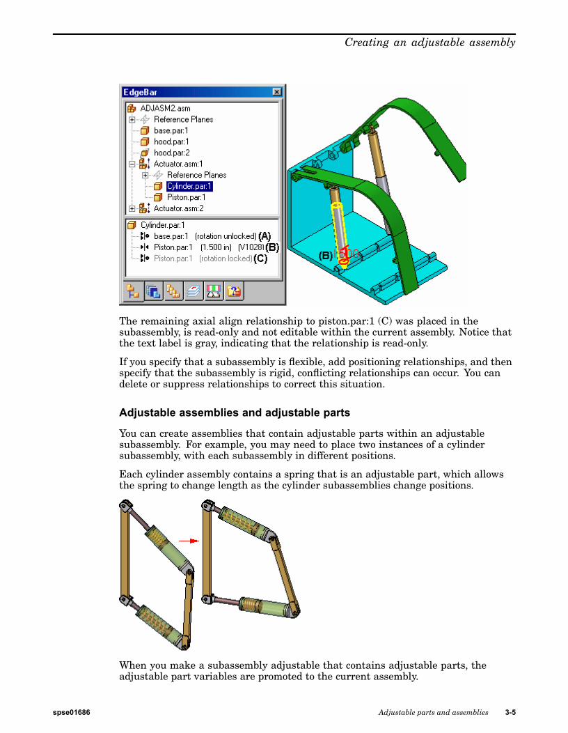
For example, when you select cylinder.par:1 in the adjustable assembly namedActuator.asm:1, three relationships are displayed. The axial align relationshipto base.par (A) was placed in the current assembly. It was used to position thesubassembly in the current assembly, and is editable.
The Mate relationship to piston.par:1 (B) was placed in the current assembly afterthe subassembly was made adjustable. Its purpose is to adjust the length of thehydraulic cylinder subassembly and the relationship is editable.
Notice that no visual distinction is made between relationships (A) and (B), althoughone of the relationships was used to position the subassembly in the currentassembly (A), and the other was used to position the two parts in the subassembly.
3-4 Adjustable parts and assemblies spse01686
Creating an adjustable assembly
The remaining axial align relationship to piston.par:1 (C) was placed in thesubassembly, is read-only and not editable within the current assembly. Notice thatthe text label is gray, indicating that the relationship is read-only.
If you specify that a subassembly is flexible, add positioning relationships, and thenspecify that the subassembly is rigid, conflicting relationships can occur. You candelete or suppress relationships to correct this situation.
Adjustable assemblies and adjustable parts
You can create assemblies that contain adjustable parts within an adjustablesubassembly. For example, you may need to place two instances of a cylindersubassembly, with each subassembly in different positions.
Each cylinder assembly contains a spring that is an adjustable part, which allowsthe spring to change length as the cylinder subassemblies change positions.
When you make a subassembly adjustable that contains adjustable parts, theadjustable part variables are promoted to the current assembly.
spse01686 Adjustable parts and assemblies 3-5

Lesson 3 Creating an adjustable assembly
If you define an assembly variable in the variable table for a subassembly thatcontrols a part variable, the subassembly variable is promoted to the currentassembly. The promoted variable is a linked variable.
For more information on creating and using adjustable parts in assemblies, see theAdjustable parts in assemblies Help topic.
Adjustable assemblies and the Drag Part command
If you specify that a subassembly is adjustable, and the combination of relationshipsat the active level and the promoted relationships allow movement, you can usethe Drag Part command to reposition the parts. Adjustable assemblies work withall modes of the Drag Part command.
Because an adjustable subassembly is typically used to drive movement in anassembly, you may need to provide for that movement by suppressing or deletingrelationships in the related parts and subassemblies.
3-6 Adjustable parts and assemblies spse01686

Creating an adjustable assembly
Activity: Creating an adjustable assemblyOverview
The objective of this activity is to show how to create an adjustable assemblyto be used in a higher level assembly.
Activity
In this activity you will create and place an adjustable assembly.
Turn to Appendix B for the activity.
spse01686 Adjustable parts and assemblies 3-7

Lesson 3 Creating an adjustable assembly
Lesson reviewAnswer the following questions:
1. What are the characteristics of an adjustable assembly?
2. How do you prepare an assembly to be adjustable?
3. If a motor exists in a subassembly and you would like to have that motor controlthe position of under constrained parts, how could you do it?
4. When a subassembly contains an under constrained part and the subassembly ismade adjustable, constraints to the under constrained part can be made in thehigher level assembly. Where can you view and edit the relationships used toposition the part?
3-8 Adjustable parts and assemblies spse01686

Creating an adjustable assembly
Answers1. What are the characteristics of an adjustable assembly?
Specifying that a subassembly is adjustable allows you to place positioningrelationships between parts in the subassembly while in the higher-levelassembly. This is not possible with a rigid subassembly.
2. How do you prepare an assembly to be adjustable?
To use the Adjustable Assembly functionality, the subassembly should be leftunder-constrained in the range of motion in which you want to adjust. Thisallows you to apply the relationship(s) that you want to adjust in the higherlevel assembly, not in the subassembly.
3. If a motor exists in a subassembly and you would like to have that motor controlthe position of under constrained parts, how could you do it?
Make the subassembly with the motor adjustable.
4. When a subassembly contains an under constrained part and the subassembly ismade adjustable, constraints to the under constrained part can be made in thehigher level assembly. Where can you view and edit the relationships used toposition the part?
You can view and edit the relationships of an under constrained part in anadjustable subassembly in the lower pane of pathfinder.
spse01686 Adjustable parts and assemblies 3-9

Lesson 3 Creating an adjustable assembly
Lesson summaryIn this lesson you placed an assembly with an adjustable part and defined theassembly as adjustable.
3-10 Adjustable parts and assemblies spse01686
A Activity: Creating anadjustable part
Overview
This activity demonstrates to create an adjustable part and place it into an assembly.
Objectives
You will create a spring and use it as an adjustable part and a rigid part in anassembly.
spse01686 Adjustable parts and assemblies A-1

A Activity: Creating an adjustable part
Creating the variable defining the adjustable distanceSketches created in a part document will be used to define the adjustable variable.
▸ From the Solid Edge start screen, click Open Existing Document. Browse forspring.par in the folder where the activity files are located.
▸ Select Sketch1 in pathfinder and then select Edit Profile to edit the sketch.
Note
This sketch will be used to create a helix defining the spring. To make thelength adjustable, a dimension controlling the length will be defined.
▸ Dimension the horizontal line in the sketch. The length is 2000 mm.
▸ Click Tools, then click Variables to show the variable table.
▸ Find the variable with the length equal to 2000 and change the name of thevariable name to spring_length.
▸ Dismiss the variable table.
▸ Click the home tab, then click Close Sketch.
▸ Click finish.
▸ Select Sketch2 in pathfinder and then select Edit Profile to edit the sketch.
A-2 Adjustable parts and assemblies spse01686

Activity: Creating an adjustable part
▸ Place a horizontal dimension between the two rectangles.
Note
The rectangles will be used to create a cutout and shave off the ends of thespring creating a planar face on each end. The spacing will be controlled bya formula in the variable table equating the spacing between the rectanglesto the spring_length variable previously defined.
▸ Click Tools, then click variables to show the variable table.
▸ Find the variable with the length equal to the horizontal dimension just created.In the formula field, set the value equal to the variable spring_length.
▸ Dismiss the variable table.
▸ Click the home tab, then click Close Sketch.
▸ Click finish.
spse01686 Adjustable parts and assemblies A-3

A Activity: Creating an adjustable part
Create the spring from the sketchesCreate the helix from the sketch1.
▸ Hide Sketch2.
▸ On the home tab, in the solids group, click add helix.
▸ Set the create from option to: Select from Sketch.
▸ Select the circle as the sketch chain and then click accept.
▸ Select the horizontal line as the axis.
▸ Select the left side of the line as the origin of the axis.
▸ Set the method to Axis length and turns and the number of turns to 15.
A-4 Adjustable parts and assemblies spse01686

Activity: Creating an adjustable part
▸ Click Next.
▸ Click Preview.
▸ Click Finish.
▸ Hide Sketch1 and show Sketch2.
▸ On the Home tab, in the Solids group, click the Cut command.
▸ Set the create from option to: Select from Sketch.
▸ Select each of the rectangles in the sketch, then click the accept button.
▸ Select the through all option for the extent of the cut.
spse01686 Adjustable parts and assemblies A-5

A Activity: Creating an adjustable part
▸ Select both directions to define the extent of the cut.
▸ Click Finish to complete the cut.
A-6 Adjustable parts and assemblies spse01686

Activity: Creating an adjustable part
Define the adjustable variableThe variable defining the axis length of the spring will be defined as the adjustablevariable.
▸ Click the Tools Tab. In the Assistants group, click Adjustable part.
▸ Click the variable table button.
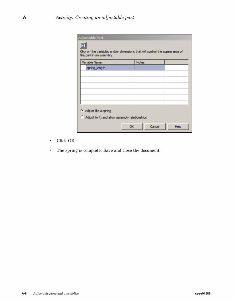
▸ Select spring_length as the adjustable variable.
▸ Dismiss the variable table. Spring_length will be defined as the adjustablevariable.
spse01686 Adjustable parts and assemblies A-7
A Activity: Creating an adjustable part
▸ Click OK.
▸ The spring is complete. Save and close the document.
A-8 Adjustable parts and assemblies spse01686

Activity: Creating an adjustable part
Place and define the adjustable part as a springThe spring will be placed and positioned in the assembly as an adjustable part.
▸ Open the assembly shock_absorber.asm.
▸ In pathfinder, right click shock_absorber.asm and then click Activate to activateall the parts.
The subassembly, shock_top.asm, examine the relationships used to position thesubassembly relative to shock_bottom.asm.
▸ In pathfinder, click shock_top.asm. In the lower pane notice that there is an axialalign relationship and a floating planar align.
Note
These relationships keep the cylindrical parts aligned and keep the holescontaining the bushing and sleeve parallel. There is still freedom to movealong the axis of the cylinders.
spse01686 Adjustable parts and assemblies A-9
A Activity: Creating an adjustable part
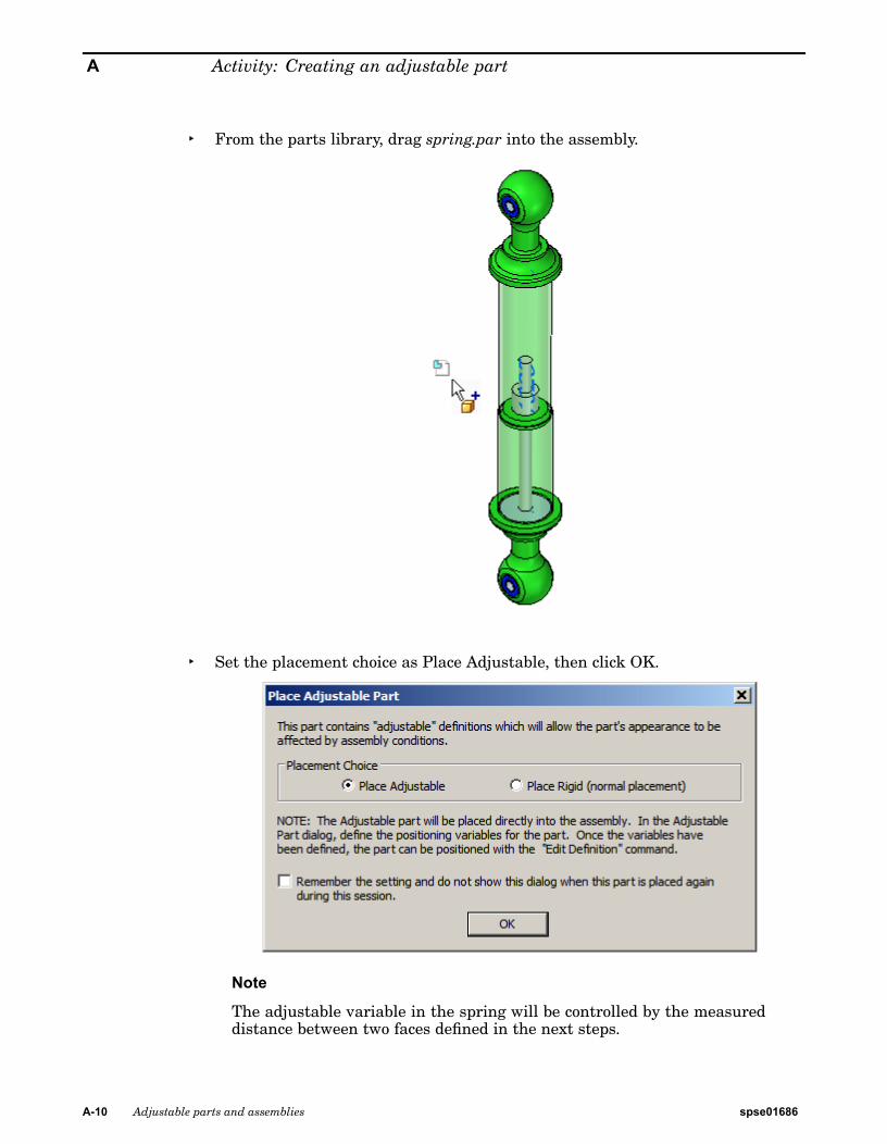
▸ From the parts library, drag spring.par into the assembly.
▸ Set the placement choice as Place Adjustable, then click OK.
Note
The adjustable variable in the spring will be controlled by the measureddistance between two faces defined in the next steps.
A-10 Adjustable parts and assemblies spse01686
Activity: Creating an adjustable part
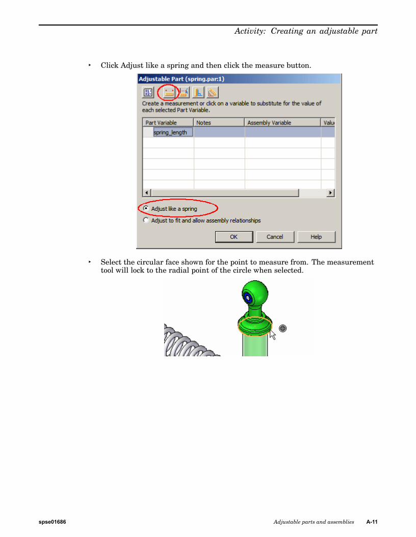
▸ Click Adjust like a spring and then click the measure button.
▸ Select the circular face shown for the point to measure from. The measurementtool will lock to the radial point of the circle when selected.
spse01686 Adjustable parts and assemblies A-11

A Activity: Creating an adjustable part
▸ Select the circular face shown for the point to measure to. The measurement toolwill lock to the radial point of the circle when selected.
Note
The adjustable distance has been set and the spring length adjusts to thedistance defined.
▸ Click OK to dismiss the dialog box.
The reference planes will be used to position the spring. The next steps will turn onthe planes needed to position the spring.
▸ Click the Select tool. Right mouse click in the assembly window. Click Show/HideAll.
A-12 Adjustable parts and assemblies spse01686
Activity: Creating an adjustable part
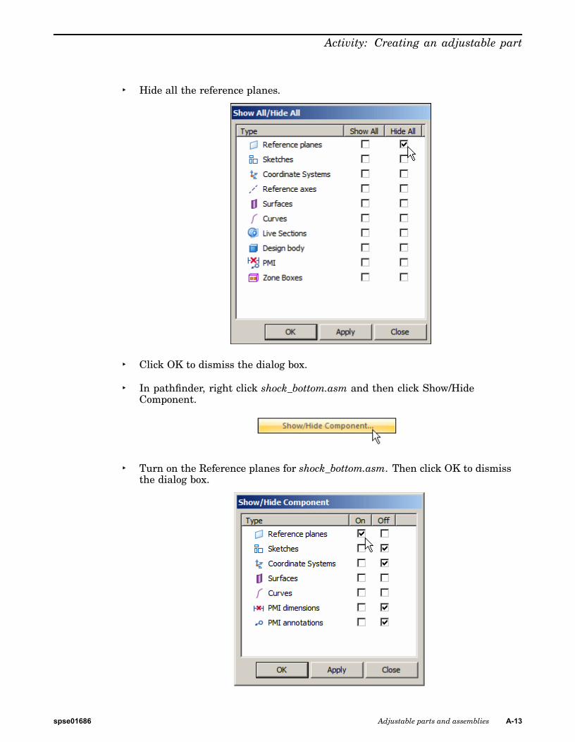
▸ Hide all the reference planes.
▸ Click OK to dismiss the dialog box.
▸ In pathfinder, right click shock_bottom.asm and then click Show/HideComponent.
▸ Turn on the Reference planes for shock_bottom.asm. Then click OK to dismissthe dialog box.
spse01686 Adjustable parts and assemblies A-13
A Activity: Creating an adjustable part
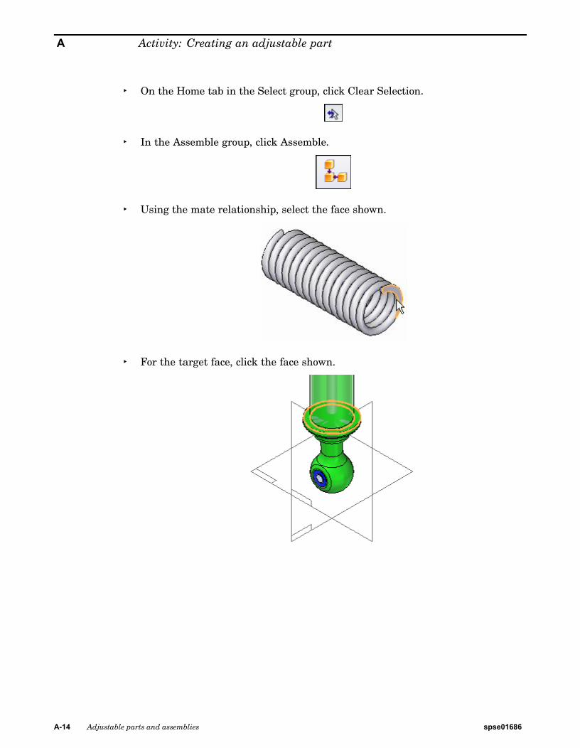
▸ On the Home tab in the Select group, click Clear Selection.
▸ In the Assemble group, click Assemble.
▸ Using the mate relationship, select the face shown.
▸ For the target face, click the face shown.
A-14 Adjustable parts and assemblies spse01686

Activity: Creating an adjustable part
▸ Using the mate relationship, select the face shown.
▸ For the target face, click the face shown.
▸ Click the construction display to turn on the reference planes for spring.par.
spse01686 Adjustable parts and assemblies A-15
A Activity: Creating an adjustable part
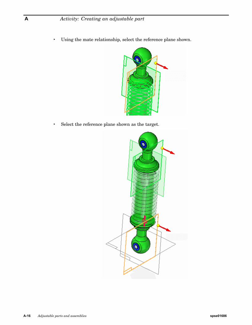
▸ Using the mate relationship, select the reference plane shown.
▸ Select the reference plane shown as the target.
A-16 Adjustable parts and assemblies spse01686

Activity: Creating an adjustable part
▸ Using the mate relationship, select the reference plane shown.
▸ Select the reference plane shown as the target.
▸ The Spring is placed.
spse01686 Adjustable parts and assemblies A-17

A Activity: Creating an adjustable part
▸ Turn off the display of the reference planes..
shock_top.asm is still free to move along the axis of the cylinders. You will move thispart and the spring will adjust size based on the position of this subassembly.
▸ Click the home tab. In the modify group, click the drag command.
A-18 Adjustable parts and assemblies spse01686

Activity: Creating an adjustable part
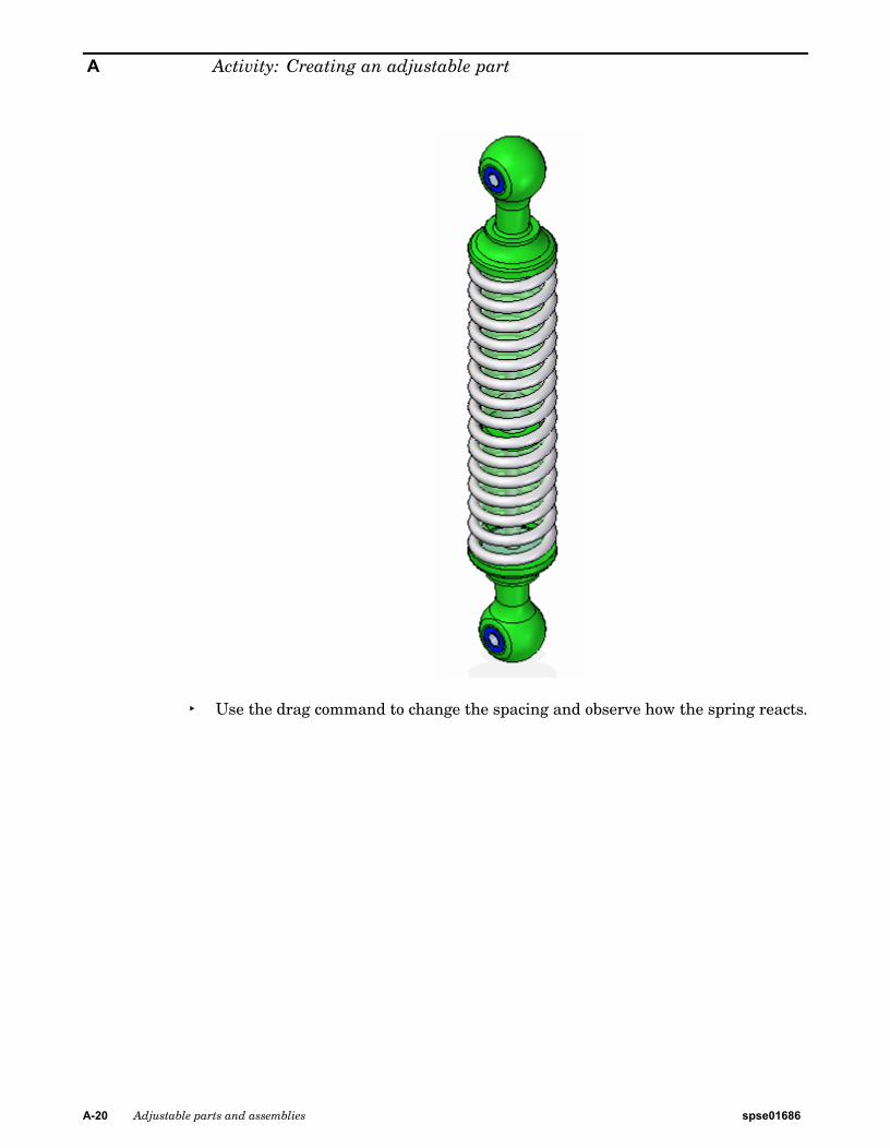
▸ Drag shock_top.asm to increase the separation distance between thesubassemblies.
▸ The spring will adjust to the spacing between the faces.
spse01686 Adjustable parts and assemblies A-19
A Activity: Creating an adjustable part
▸ Use the drag command to change the spacing and observe how the spring reacts.
A-20 Adjustable parts and assemblies spse01686

Activity: Creating an adjustable part
Define the adjustable part as a rigid partPreviously, the spring was set to adjust as a spring. The length of the spring wasdetermined by the spacing between two faces on different parts. The adjustable partalso be used to determine the spacing between the faces which removes the freedomto move and makes the assembly rigid. This will be demonstrated in the next steps.
▸ Notice the icon in pathfinder for the subassembly shock_top.asm shows it asunder constrained.
▸ Click the select tool. In pathfinder, right click spring.par. ClickSimplified/Adjustable. Click Edit Adjustable Part.
▸ Change the behavior to Adjust to fit and allow assembly relationships, and enter1250 as the Assembly Variable value as shown.
▸ Click OK. Notice that shock_top.asm is now constrained and the variabledefining spring length determines the offset value.
spse01686 Adjustable parts and assemblies A-21

A Activity: Creating an adjustable part
▸ Save and close the document. This completes the activity.
A-22 Adjustable parts and assemblies spse01686

Activity: Creating an adjustable part
SummaryIn this activity you learned how to create and adjustable part and place it in anassembly as a spring, or to adjust the fit to allow assembly relationships.
spse01686 Adjustable parts and assemblies A-23


B Activity: Creating an adjustableassembly
Overview
This activity demonstrates to create an adjustable assemble.
Objectives
You will place an assembly and define it as adjustable. The assembly will containan adjustable part.
spse01686 Adjustable parts and assemblies B-1

B Activity: Creating an adjustable assembly
Place an assembly containing an adjustable part into a higher levelassembly
The assembly you will place will later be defined as adjustable.
▸ Open the assembly arms.asm. Activate all the parts in the assembly.
▸ From the parts library, drag shock_absorber1.asm into the assembly window.
▸ Click the activate button on the assemble command toolbar.
B-2 Adjustable parts and assemblies spse01686
Activity: Creating an adjustable assembly
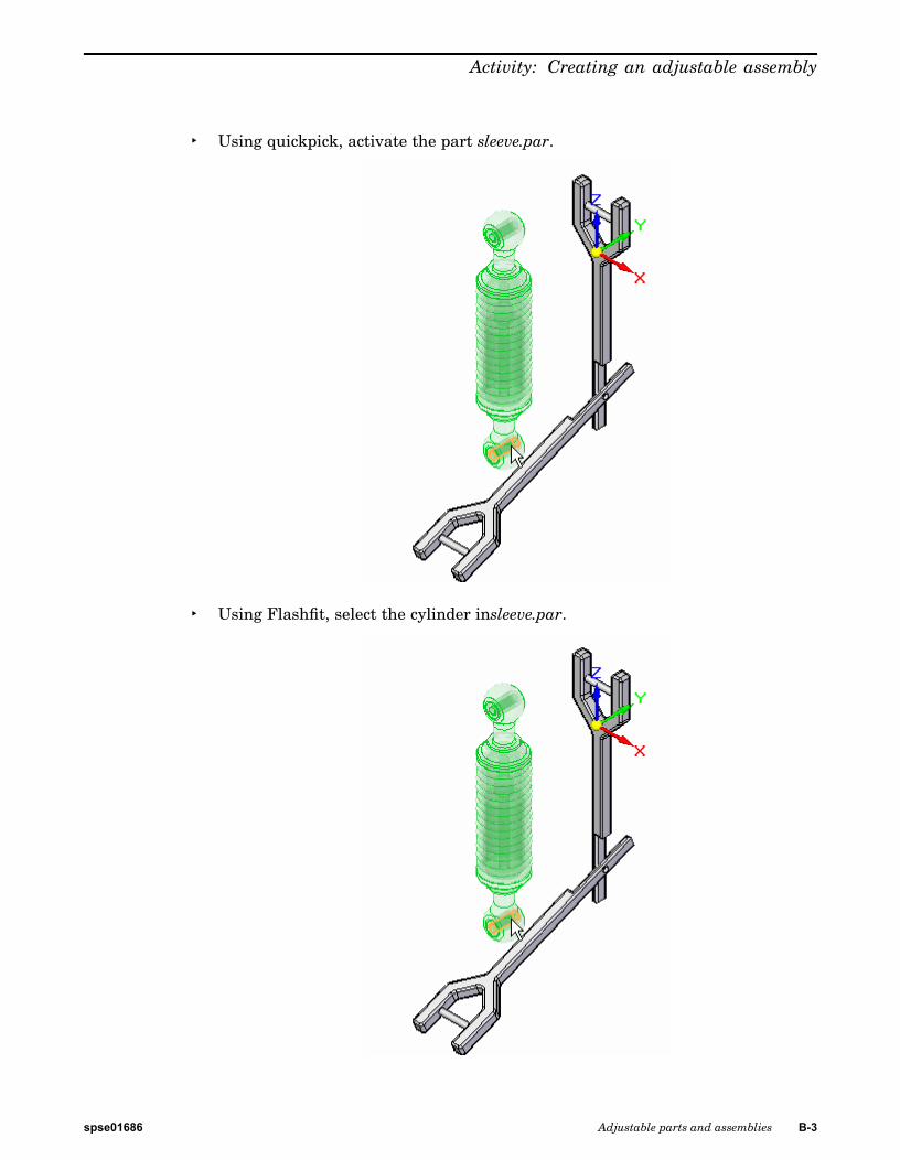
▸ Using quickpick, activate the part sleeve.par.
▸ Using Flashfit, select the cylinder insleeve.par.
spse01686 Adjustable parts and assemblies B-3

B Activity: Creating an adjustable assembly
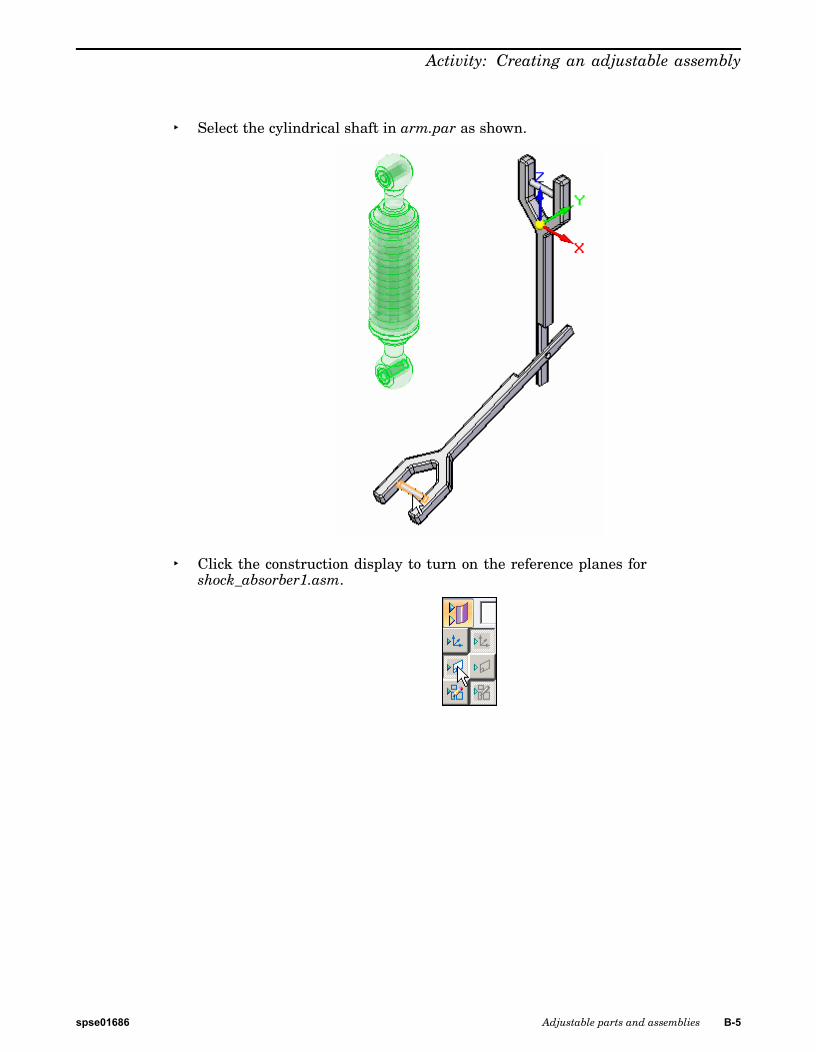
▸ Select the cylindrical shaft in arm.par as shown.
▸ For the next relationship select the cylinder in sleeve.par as shown.
B-4 Adjustable parts and assemblies spse01686
Activity: Creating an adjustable assembly
▸ Select the cylindrical shaft in arm.par as shown.
▸ Click the construction display to turn on the reference planes forshock_absorber1.asm.
spse01686 Adjustable parts and assemblies B-5

B Activity: Creating an adjustable assembly
▸ Select the reference plane shown.
▸ Select the face shown in arm.par.
Note
The subassembly is placed and is fully constrained.
B-6 Adjustable parts and assemblies spse01686

Activity: Creating an adjustable assembly
▸ Observe in pathfinder that all the parts of the assembly are fully positioned.
spse01686 Adjustable parts and assemblies B-7

B Activity: Creating an adjustable assembly
Make the assembly adjustable.The assembly you will place will be defined as adjustable.
▸ Click the Select tool. In pathfinder, right click the subassemblyshock_absorber1.asm. Click Simplified/Adjustable then click AdjustableAssembly.
▸ Click OK to accept the warning message shown.
▸ Observe in pathfinder that all the parts of the assembly are not fully positioned.Because the assembly is adjustable, the arm has freedom to move.
B-8 Adjustable parts and assemblies spse01686

Activity: Creating an adjustable assembly
▸ Click the home tab. In the modify group, click the drag command.
▸ Drag arm.par as shown into different positions. Observe how the spacingbetween the cylinders adjusts and that the spring adjusts to the spacing definedby the new location of the arm.
▸ Drag the arm to several different positions and observe how the assemblyadjusts.
spse01686 Adjustable parts and assemblies B-9

B Activity: Creating an adjustable assembly
Note
The assembly shock_absorber1.asm has a mate relationship defined with arange offset. This limits the range of travel for the shock absorber.
▸ Save and close the assembly. This completes this activity.
Note
Motors defined in the top level of an assembly will move under constrainedparts. If an subassembly contains a motor, the motor will not move theunconstrained parts unless the subassembly is made adjustable.
B-10 Adjustable parts and assemblies spse01686

Activity: Creating an adjustable assembly
SummaryIn this activity you placed an assembly with an adjustable part and defined theassembly as adjustable.
spse01686 Adjustable parts and assemblies B-11