addressing the challenges of wideband radar and … and satcom measurements presented by: giuseppe...
TRANSCRIPT
Copyright © 2011 Agilent Technologies
2011 Agilent RF/uW Symposium
Addressing the Challenges of Wideband Radar and SatCom Measurements
Presented by: Giuseppe Savoia, Agilent Technologies
Copyright © 2011 Agilent Technologies
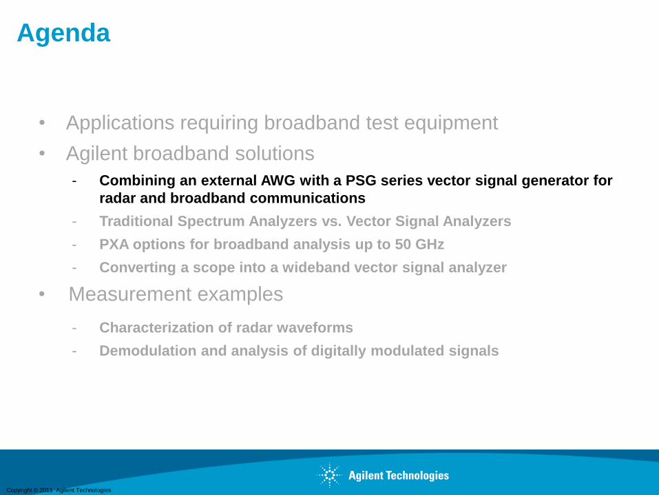
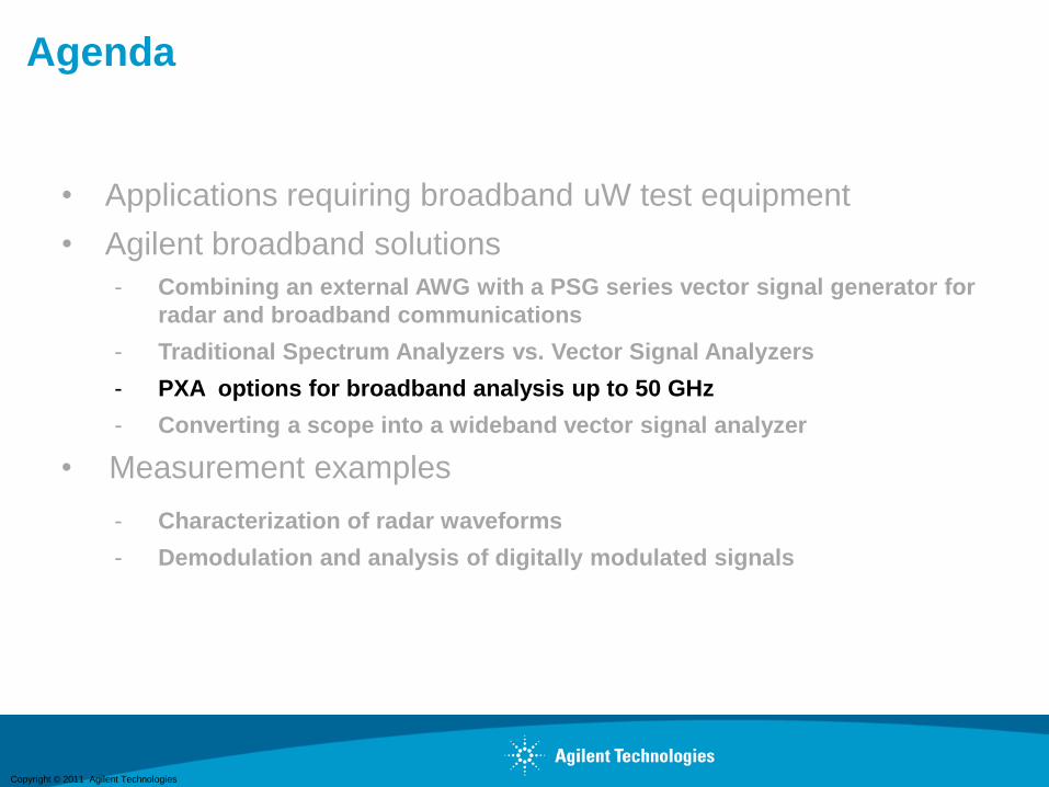
Agenda
• Applications requiring broadband uW test equipment
• Agilent broadband solutions
- Combining an external AWG with a PSG series vector signal generator for
radar and broadband communications
- Traditional Spectrum Analyzers vs. Vector Signal Analyzers
- PXA options for broadband analysis up to 50 GHz
- Converting a scope into a wideband vector signal analyzer
• Measurement examples
- Characterization of radar waveforms
- Demodulation and analysis of digitally modulated signals
Copyright © 2011 Agilent Technologies
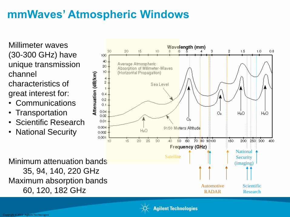
mmWaves’ Atmospheric Windows
Automotive
RADAR
Scientific
Research
National
Security
(imaging)
Satellite
Millimeter waves
(30-300 GHz) have
unique transmission
channel
characteristics of
great interest for:
• Communications
• Transportation
• Scientific Research
• National Security
Minimum attenuation bands
35, 94, 140, 220 GHz
Maximum absorption bands
60, 120, 182 GHz

Copyright © 2011 Agilent Technologies
Atmospheric Windows for Satellite
Communications
O2/H2O
Minimum attenuation band:
35, 94, 140, 220 GHz
• Most effective for the satellite-
earth signal transmissions ?
Maximum absorption band:
60, 120, 182 GHz
• Hard to be intercepted
• Effective for secured inter-
satellite transmissions
Copyright © 2011 Agilent Technologies
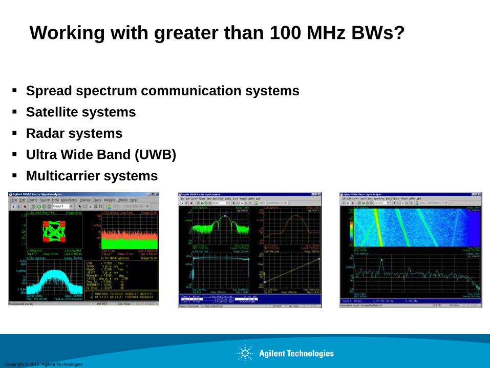
Spread spectrum communication systems
Satellite systems
Radar systems
Ultra Wide Band (UWB)
Multicarrier systems
Working with greater than 100 MHz BWs?
Copyright © 2011 Agilent Technologies
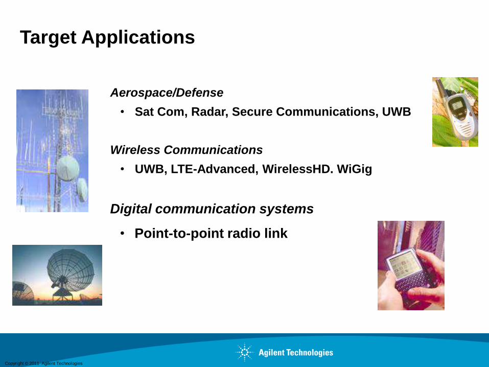
Target Applications
Aerospace/Defense
• Sat Com, Radar, Secure Communications, UWB
Wireless Communications
• UWB, LTE-Advanced, WirelessHD. WiGig
Digital communication systems
• Point-to-point radio link

Copyright © 2011 Agilent Technologies
Wideband applications:
Last-mile
backhaul for
field Military &
Commercial
data links
A/D Applications: Satellite/Mil Comms and Radar/EW
It was predicted that:
Military applications
of WiMax and other
emerging comms.
• Sat Transponders
• Point-to-point Military radios
• Pulse compression radar
• Electronic warfare (EW)
Copyright © 2011 Agilent Technologies
Agenda
• Applications requiring broadband test equipment
• Agilent broadband solutions
- Combining an external AWG with a PSG series vector signal generator for
radar and broadband communications
- Traditional Spectrum Analyzers vs. Vector Signal Analyzers
- PXA options for broadband analysis up to 50 GHz
- Converting a scope into a wideband vector signal analyzer
• Measurement examples
- Characterization of radar waveforms
- Demodulation and analysis of digitally modulated signals
Copyright © 2011 Agilent Technologies
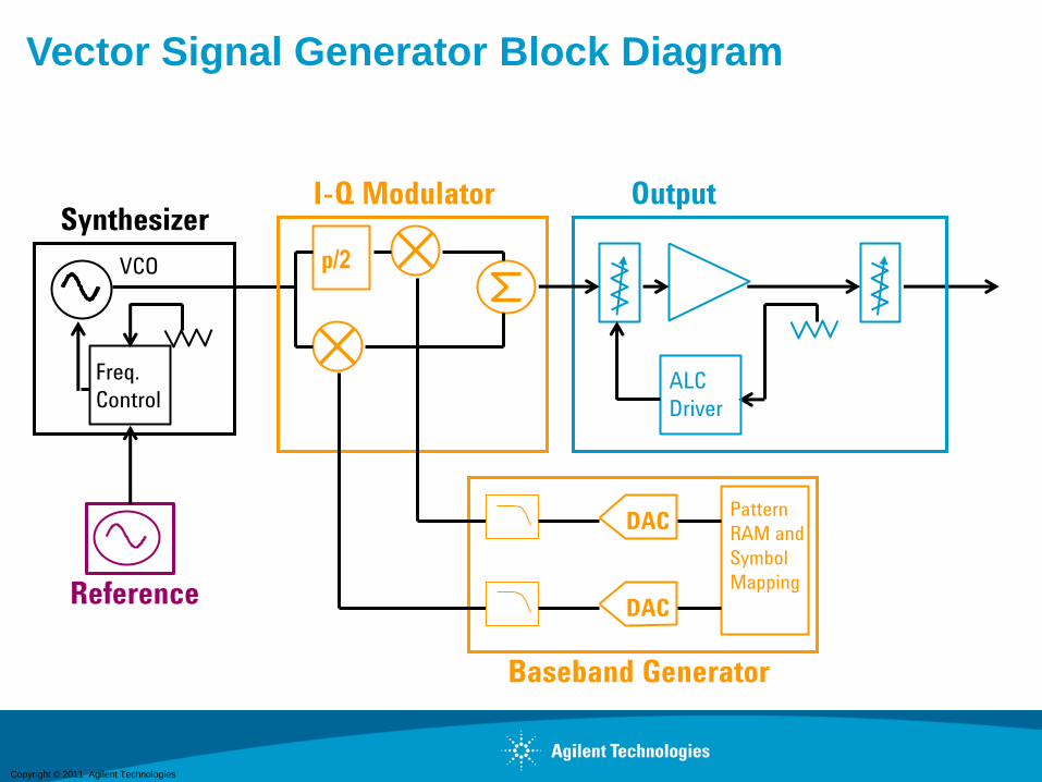
Vector Signal Generator Block Diagram
Freq.
ControlALC
Driver
Pattern
RAM and
Symbol
Mapping
VCO
Synthesizer
Reference
OutputI-Q Modulator
Baseband Generator
p/2
DAC
DAC
Copyright © 2011 Agilent Technologies
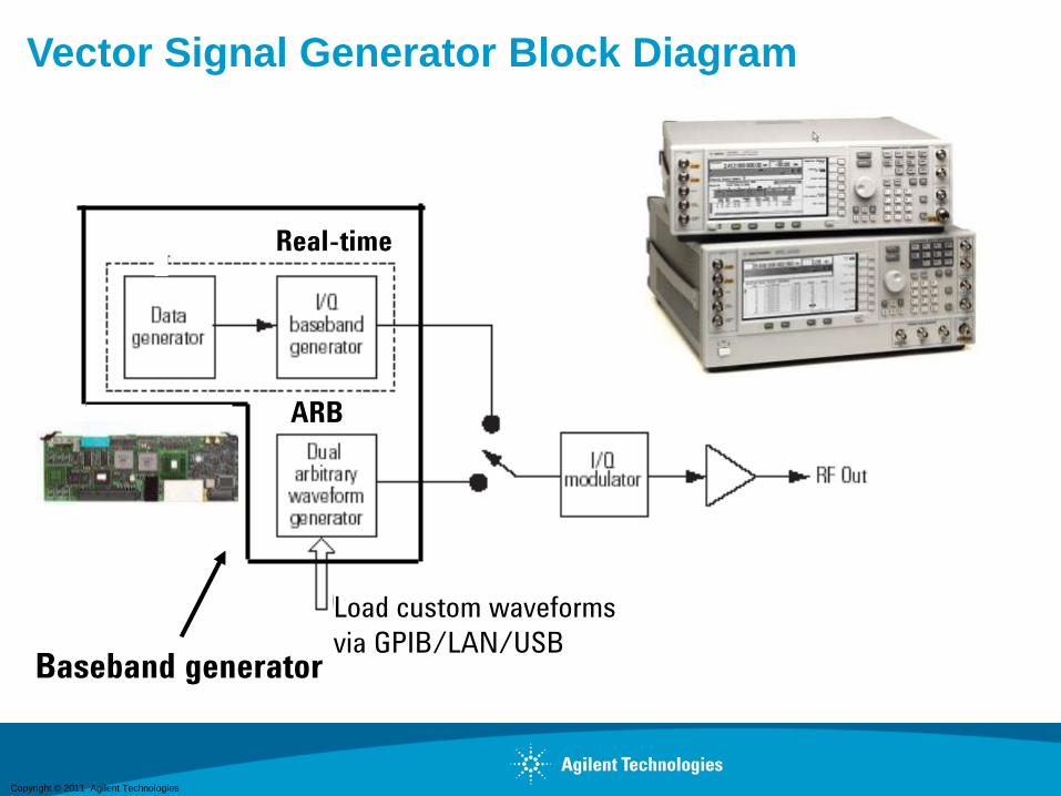
GPIB/LAN
ARB
Baseband generator
Real-time
Load custom waveforms
via GPIB/LAN/USB
Vector Signal Generator Block Diagram
Copyright © 2011 Agilent Technologies
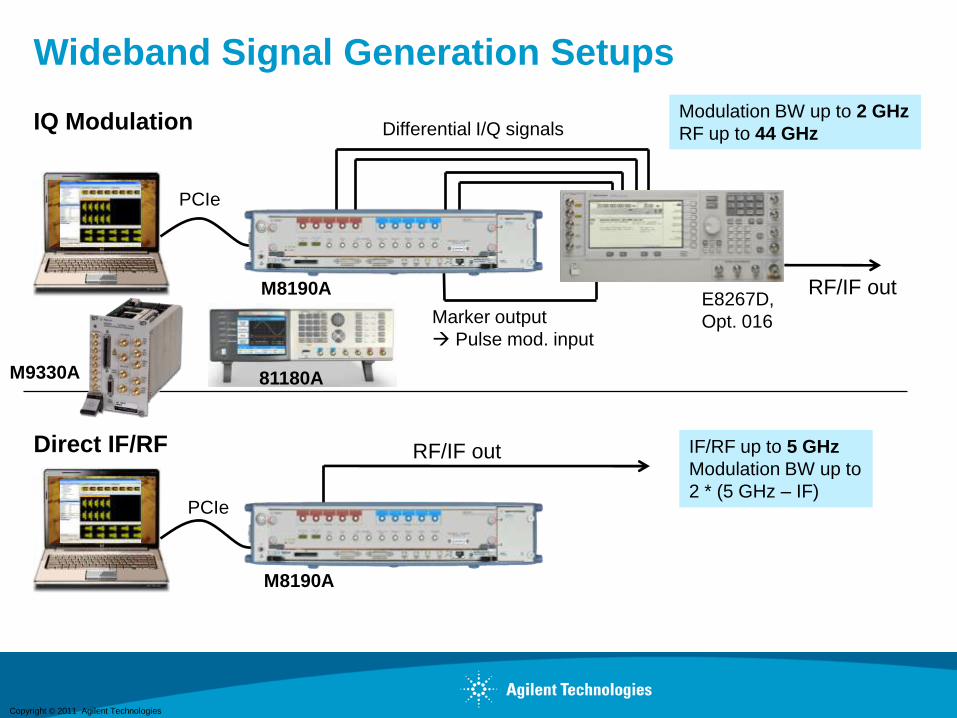
Wideband Signal Generation Setups
Differential I/Q signals
RF/IF out
RF/IF out
Marker output
Pulse mod. input
PCIe
PCIe
M8190AE8267D,
Opt. 016
M8190A
Modulation BW up to 2 GHz
RF up to 44 GHz
IF/RF up to 5 GHz
Modulation BW up to
2 * (5 GHz – IF)
IQ Modulation
Direct IF/RF
11
81180AM9330A
Copyright © 2011 Agilent TechnologiesPage 12
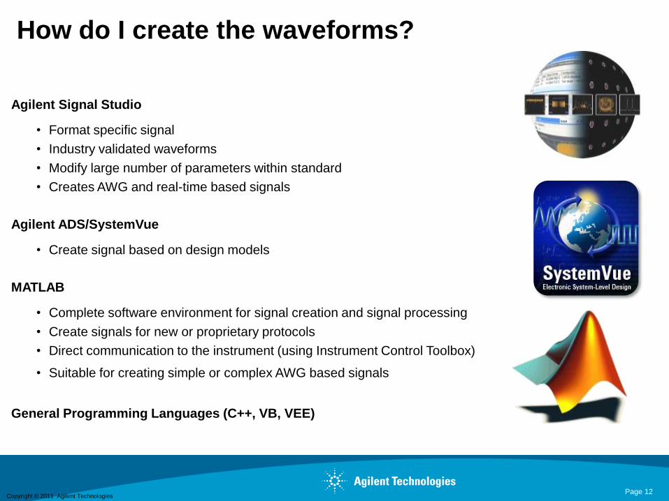
How do I create the waveforms?
Agilent Signal Studio
• Format specific signal
• Industry validated waveforms
• Modify large number of parameters within standard
• Creates AWG and real-time based signals
Agilent ADS/SystemVue
• Create signal based on design models
MATLAB
• Complete software environment for signal creation and signal processing
• Create signals for new or proprietary protocols
• Direct communication to the instrument (using Instrument Control Toolbox)
• Suitable for creating simple or complex AWG based signals
General Programming Languages (C++, VB, VEE)

Copyright © 2011 Agilent Technologies
Agenda
• Applications requiring broadband uW test equipment
• Agilent broadband solutions
- Combining an external AWG with a PSG series vector signal generator for
radar and broadband communications
- Traditional Spectrum Analyzers vs. Vector Signal Analyzers
- PXA options for broadband analysis up to 50 GHz
- Converting a scope into a wideband vector signal analyzer
• Measurement examples
- Characterization of radar waveforms
- Demodulation and analysis of digitally modulated signals

Copyright © 2011 Agilent TechnologiesBroadband Generation and
Analysis Solutions
Gen 2008
Page 14
Theory of OperationSwept Spectrum Analyzer Block Diagram
Pre-Selector
Or Low Pass
Input Filter
Crystal
Reference
Oscillator
Log
Amp
RF input
attenuator
mixer
IF filter
(RBW)envelope
detector
video
filterlocal
oscillator
sweep
generator
IF gain
Input
signal
ADC, Display
& Video
Processing
Copyright © 2011 Agilent Technologies
Broadband Generation and Analysis
Solutions
Gen 2008Page 15
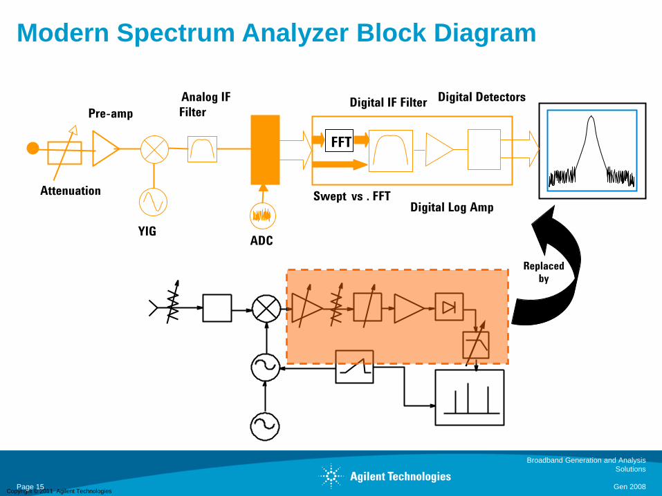
Modern Spectrum Analyzer Block Diagram
YIGADC
Analog IF
FilterDigital IF Filter
Digital Log Amp
Digital Detectors
FFT
Swept vs . FFTAttenuation
Pre-amp
Replaced
by
Copyright © 2011 Agilent Technologies
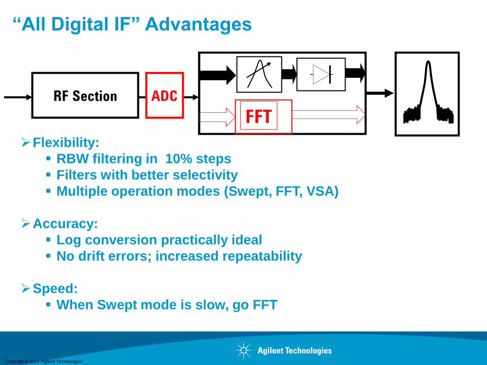
“All Digital IF” Advantages
RF Section ADC
IF/BB Section
on ASIC
Flexibility:
RBW filtering in 10% steps
Filters with better selectivity
Multiple operation modes (Swept, FFT, VSA)
Accuracy:
Log conversion practically ideal
No drift errors; increased repeatability
Speed:
When Swept mode is slow, go FFT
FFT
Copyright © 2011 Agilent Technologies
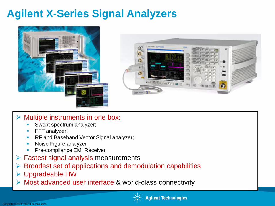
Agilent X-Series Signal Analyzers
Multiple instruments in one box: Swept spectrum analyzer;
FFT analyzer;
RF and Baseband Vector Signal analyzer;
Noise Figure analyzer
Pre-compliance EMI Receiver
Fastest signal analysis measurements
Broadest set of applications and demodulation capabilities
Upgradeable HW
Most advanced user interface & world-class connectivity
Copyright © 2011 Agilent Technologies
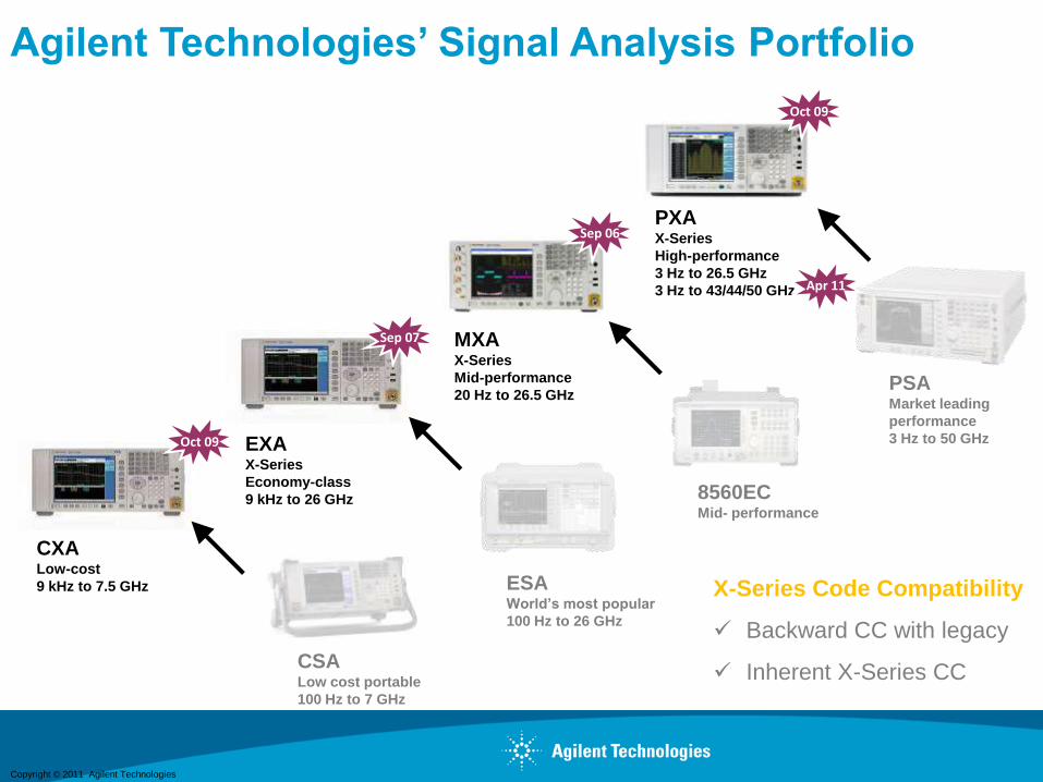
Agilent Technologies’ Signal Analysis Portfolio
ESAWorld’s most popular
100 Hz to 26 GHz
8560ECMid- performance
EXAX-Series
Economy-class
9 kHz to 26 GHz
Sep 07
PSAMarket leading
performance
3 Hz to 50 GHz
CXALow-cost
9 kHz to 7.5 GHz
Oct 09
CSALow cost portable
100 Hz to 7 GHz
MXAX-Series
Mid-performance
20 Hz to 26.5 GHz
Sep 06
X-Series Code Compatibility
Backward CC with legacy
Inherent X-Series CC
Oct 09
PXAX-Series
High-performance
3 Hz to 26.5 GHz
3 Hz to 43/44/50 GHz Apr 11
Copyright © 2011 Agilent Technologies
Agenda
• Applications requiring broadband uW test equipment
• Agilent broadband solutions
- Combining an external AWG with a PSG series vector signal generator for
radar and broadband communications
- Traditional Spectrum Analyzers vs. Vector Signal Analyzers
- PXA options for broadband analysis up to 50 GHz
- Converting a scope into a wideband vector signal analyzer
• Measurement examples
- Characterization of radar waveforms
- Demodulation and analysis of digitally modulated signals
Copyright © 2011 Agilent Technologies
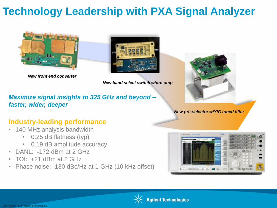
Technology Leadership with PXA Signal Analyzer
New front end converter
New pre-selector w/YIG tuned filter
New band select switch w/pre-amp
Maximize signal insights to 325 GHz and beyond –
faster, wider, deeper
Industry-leading performance• 140 MHz analysis bandwidth
• 0.25 dB flatness (typ)
• 0.19 dB amplitude accuracy
• DANL: -172 dBm at 2 GHz
• TOI: +21 dBm at 2 GHz
• Phase noise: -130 dBc/Hz at 1 GHz (10 kHz offset)

Copyright © 2011 Agilent Technologies
50 GHz
Low frequency
Oscilloscope
DSO90204
2.5 GHz + VSA
PXA as a Millimeter Downconverter(PXA Downconversion Extended to 50 GHz)
Adjustable IF Outputs
Fast Video Out, Including Preselector Bypass
Fast Log Video Out
Temporal analysis of radar pulses and pulsed EW RF
Trigger other devices
Wideband Output, 600-800 MHz Bandwidth
Digitize with Oscilloscope or Other
Analyze with 89600B VSA
Copyright © 2011 Agilent Technologies
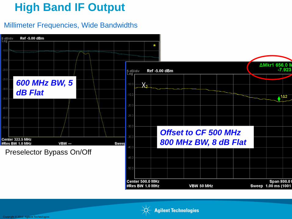
High Band IF Output
Millimeter Frequencies, Wide Bandwidths
22
Preselector Bypass On/Off
600 MHz BW, 5
dB Flat
Offset to CF 500 MHz
800 MHz BW, 8 dB Flat

Copyright © 2011 Agilent Technologies
Agenda
• Applications requiring broadband uW test equipment
• Agilent broadband solutions
- Combining an external AWG with a PSG series vector signal generator for
radar and broadband communications
- Traditional Spectrum Analyzers vs. Vector Signal Analyzers
- PXA options for broadband analysis up to 50 GHz
- Converting a scope into a wideband vector signal analyzer
• Measurement examples
- Characterization of radar waveforms
- Demodulation and analysis of digitally modulated signals

Copyright © 2011 Agilent Technologies
RF Down-
Converter
Analysis
& Display
Engine
What is Vector Signal Analysis? Signal Acquisition Hardware
Blocks ofI-Q Samples
A-to-D
Converter

Copyright © 2011 Agilent Technologies
•
•
••
•
••
•
•
•
••
•
•
•
•
•
•
digitized waveformFront End
Windows O/S
constellation
eye diagram
waveform
Windows GUI
spectrum
User
Applications
COM layer
GUI, I/O, etc.
Display
Engine
Signal Analysis
Algorithms
What is Vector Signal Analysis?Signal Processing Software
•
Copyright © 2011 Agilent Technologies
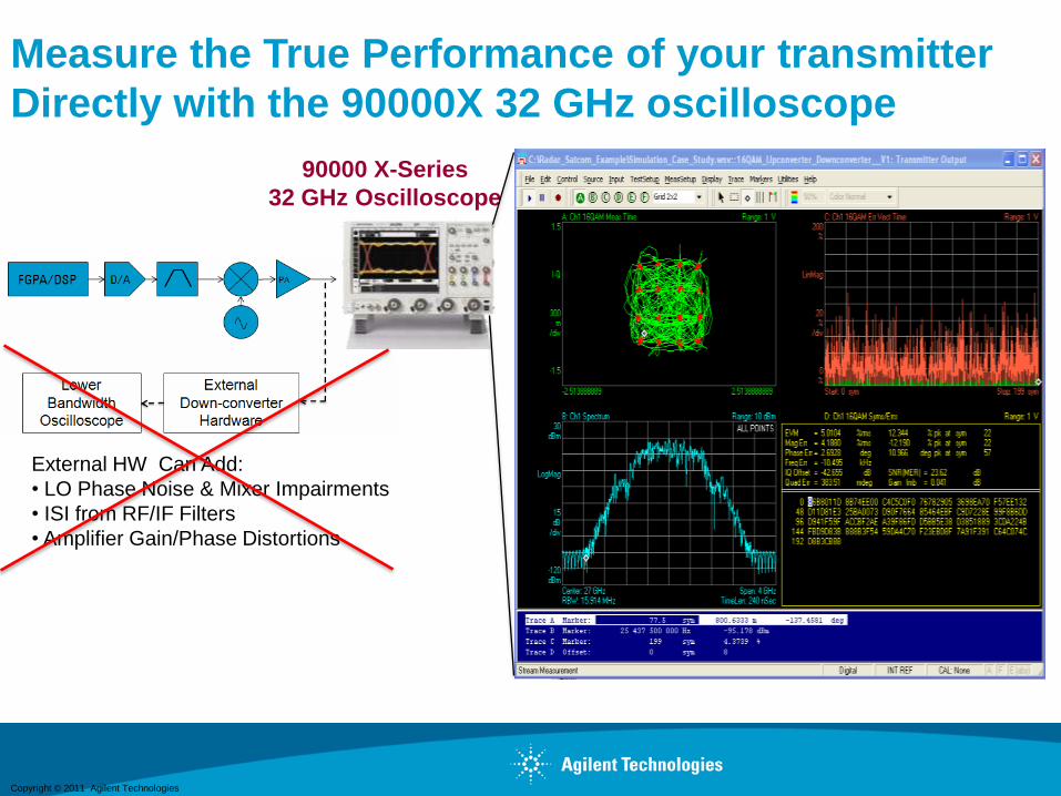
External HW Can Add:
• LO Phase Noise & Mixer Impairments
• ISI from RF/IF Filters
• Amplifier Gain/Phase Distortions
Measure the True Performance of your transmitter
Directly with the 90000X 32 GHz oscilloscope
90000 X-Series
32 GHz Oscilloscope
Copyright © 2011 Agilent Technologies
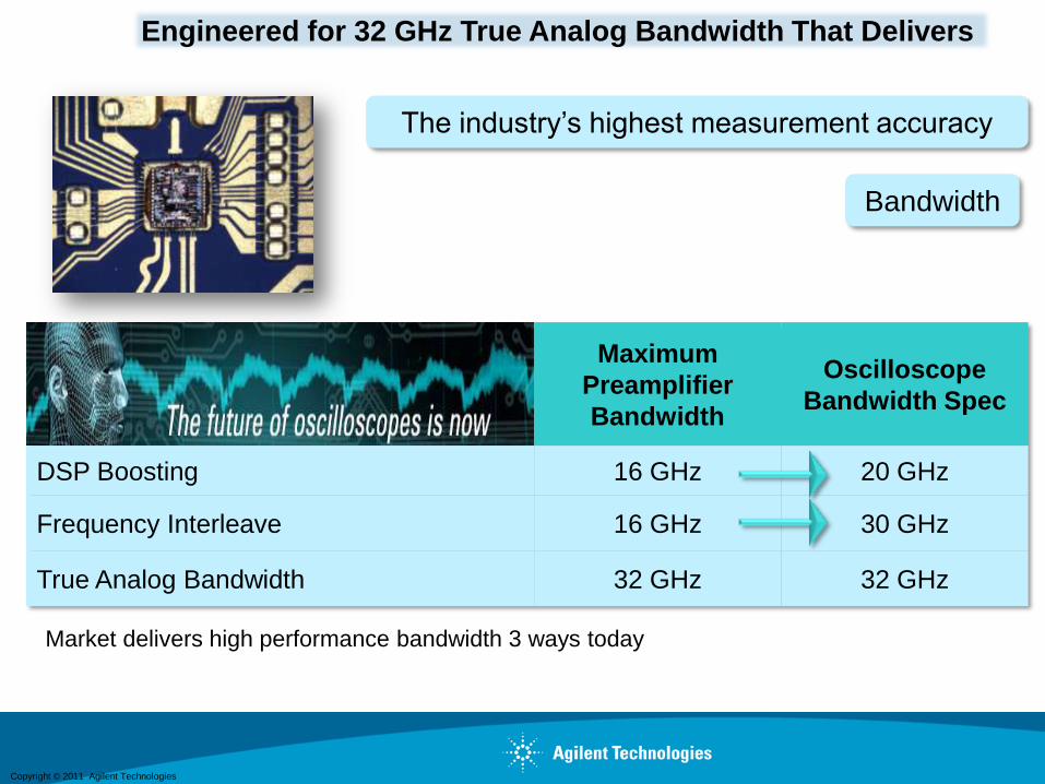
Engineered for 32 GHz True Analog Bandwidth That Delivers
Market delivers high performance bandwidth 3 ways today
The industry’s highest measurement accuracy
Bandwidth
Maximum
Preamplifier
Bandwidth
Oscilloscope
Bandwidth Spec
DSP Boosting 16 GHz 20 GHz
Frequency Interleave 16 GHz 30 GHz
True Analog Bandwidth 32 GHz 32 GHz
Copyright © 2011 Agilent Technologies
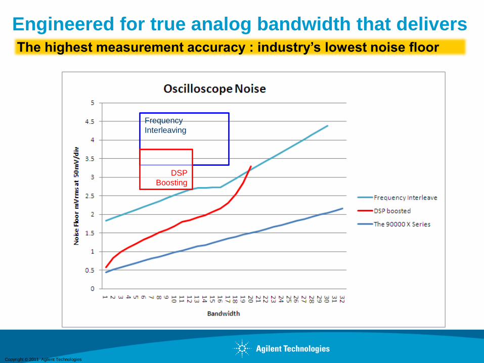
The highest measurement accuracy : industry’s lowest noise floor
Engineered for true analog bandwidth that delivers
Frequency
Interleaving
DSP
Boosting
Copyright © 2011 Agilent Technologies
0
5
10
15
20
25
0 50 100 150 200 250 300 3500 50 100 150 200 250 300 350
Ft (GHz)
BV
ce
o(V
olt
s)
25
20
15
10
5
0
UM
NGST
Agilent
Agilent & SFU
Research
InP
DHBT
InP SHBT
& GaAs
HRL
TRW
NTT
Si &
SiGe
HB2A
IBM HP8HitachiIBM •
IBM HP7
GCS
Agilent’s Proprietary
InP HBT Process
Enabled by Unique
HFTC GaAsSb Epi
HB2BAgilent
St-9MW
Jazz
0
5
10
15
20
25
0 50 100 150 200 250 300 3500 50 100 150 200 250 300 350
Ft (GHz)
BV
ce
o(V
olt
s)
25
20
15
10
5
0
UM
NGST
Agilent
Agilent & SFU
Research
InP
DHBT
InP SHBT
& GaAs
HRL
TRW
NTT
Si &
SiGe
HB2A
IBM HP8HitachiIBM •
IBM HP7
GCS
Agilent’s Proprietary
InP HBT Process
Enabled by Unique
HFTC GaAsSb Epi
HB2BAgilent
St-9MW
Jazz
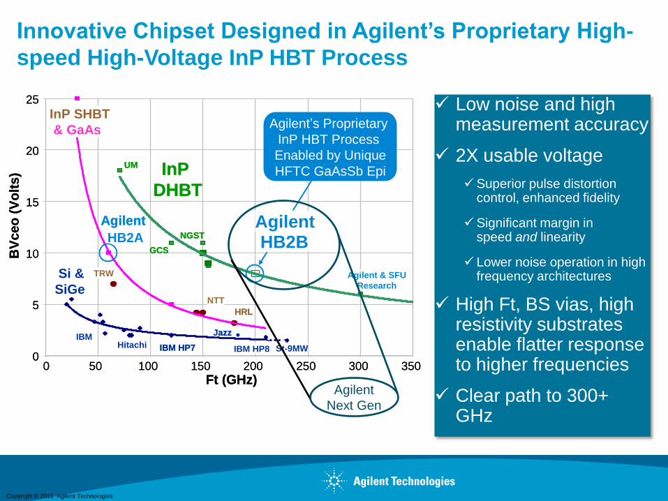
Innovative Chipset Designed in Agilent’s Proprietary High-
speed High-Voltage InP HBT Process
Low noise and high measurement accuracy
2X usable voltage
Superior pulse distortion control, enhanced fidelity
Significant margin in speed and linearity
Lower noise operation in high frequency architectures
High Ft, BS vias, high resistivity substrates enable flatter response to higher frequencies
Clear path to 300+ GHz
Agilent
Next Gen
Copyright © 2011 Agilent Technologies
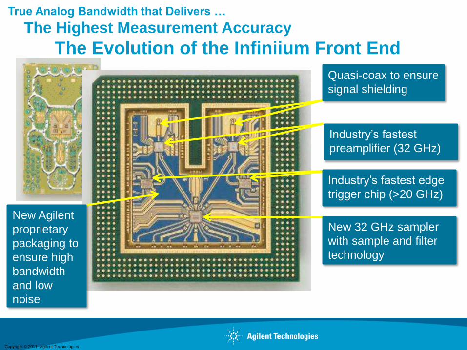
True Analog Bandwidth that Delivers …
The Highest Measurement Accuracy
The Evolution of the Infiniium Front End
Quasi-coax to ensure
signal shielding
Industry’s fastest
preamplifier (32 GHz)
Industry’s fastest edge
trigger chip (>20 GHz)
New 32 GHz sampler
with sample and filter
technology
New Agilent
proprietary
packaging to
ensure high
bandwidth
and low
noise
Copyright © 2011 Agilent Technologies
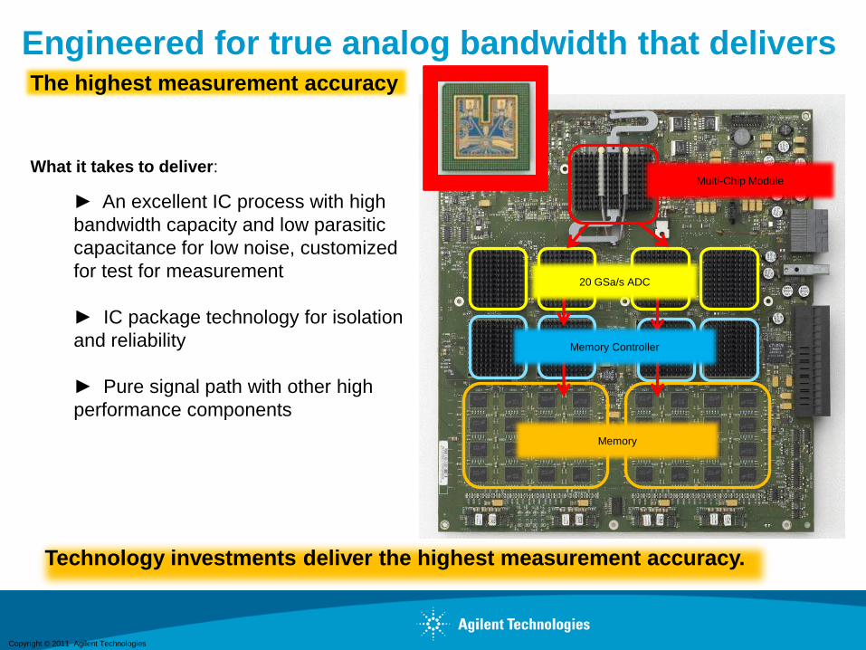
Technology investments deliver the highest measurement accuracy.
Engineered for true analog bandwidth that delivers
20 GSa/s ADC
Memory Controller
Multi-Chip ModuleWhat it takes to deliver:
► An excellent IC process with high
bandwidth capacity and low parasitic
capacitance for low noise, customized
for test for measurement
► IC package technology for isolation
and reliability
► Pure signal path with other high
performance components
Memory
The highest measurement accuracy
Copyright © 2011 Agilent TechnologiesPage 32
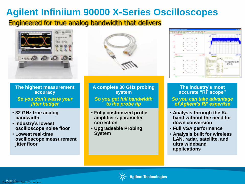
Agilent Infiniium 90000 X-Series OscilloscopesEngineered for true analog bandwidth that delivers
The highest measurement accuracy
So you don’t waste your jitter budget
• 32 GHz true analog bandwidth
• Industry’s lowest oscilloscope noise floor
• Lowest real-time oscilloscope measurement jitter floor
A complete 30 GHz probing system
So you get full bandwidth to the probe tip
• Fully customized probe amplifier s-parameter correction
• Upgradeable Probing System
The industry’s most accurate “RF scope”
So you can take advantage of Agilent’s RF expertise
• Analysis through the Ka band without the need for down conversion
• Full VSA performance
• Analysis built for wireless LAN, radar, satellite, and ultra wideband applications

Copyright © 2011 Agilent Technologies
Agenda
• Applications requiring broadband uW test equipment
• Agilent broadband solutions
- Combining an external AWG with a PSG series vector signal generator for
radar and broadband communications
- Traditional Spectrum Analyzers vs. Vector Signal Analyzers
- PXA options for broadband analysis up to 50 GHz
- Converting a scope into a wideband vector signal analyzer
• Measurement examples
- Characterization of radar waveforms
- Demodulation and analysis of digitally modulated signals
Copyright © 2011 Agilent Technologies
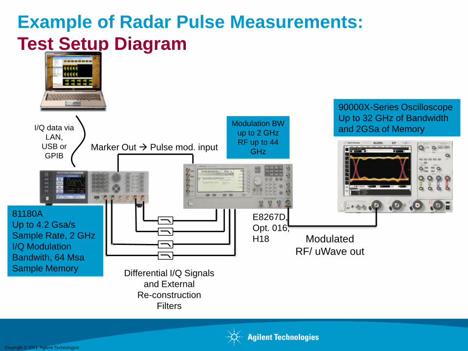
Example of Radar Pulse Measurements:
Test Setup Diagram
34
Differential I/Q Signals
and External
Re-construction
Filters
Modulated
RF/ uWave out
Marker Out Pulse mod. input
I/Q data via
LAN,
USB or
GPIB
Modulation BW
up to 2 GHz
RF up to 44
GHz
81180A
Up to 4.2 Gsa/s
Sample Rate, 2 GHz
I/Q Modulation
Bandwith, 64 Msa
Sample Memory
E8267D,
Opt. 016,
H18
90000X-Series Oscilloscope
Up to 32 GHz of Bandwidth
and 2GSa of Memory
Copyright © 2011 Agilent Technologies
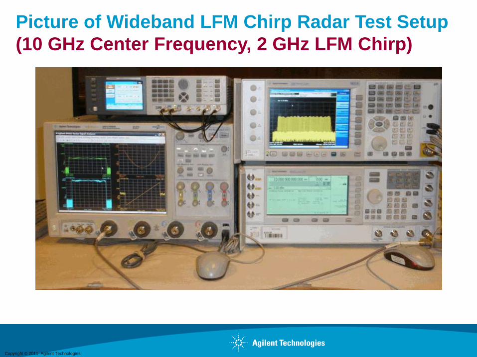
Picture of Wideband LFM Chirp Radar Test Setup
(10 GHz Center Frequency, 2 GHz LFM Chirp)
35

Copyright © 2011 Agilent Technologies
Generate a Multi-Tone Signal
36
Copyright © 2011 Agilent Technologies
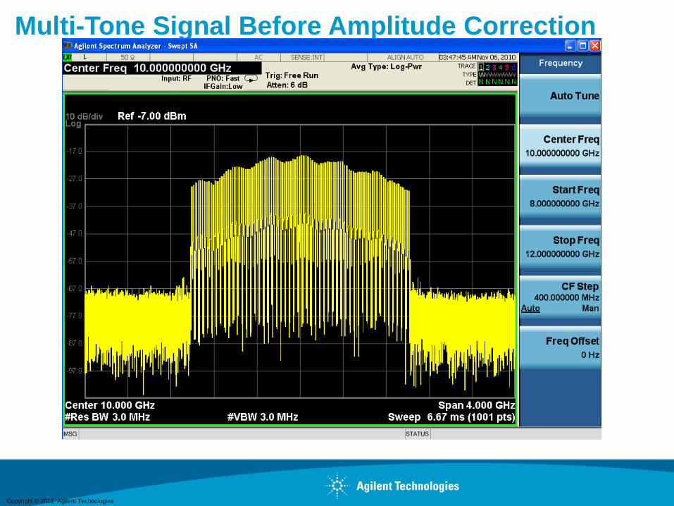
Multi-Tone Signal Before Amplitude Correction
37

Copyright © 2011 Agilent Technologies
Amplitude Flatness Correction
38
Copyright © 2011 Agilent Technologies
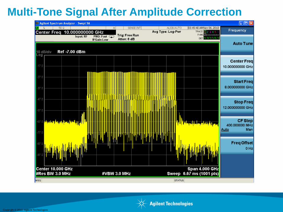
Multi-Tone Signal After Amplitude Correction
39
Copyright © 2011 Agilent Technologies
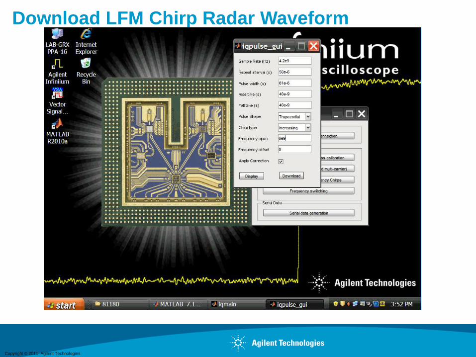
Download LFM Chirp Radar Waveform
40

Copyright © 2011 Agilent Technologies
90000X Wideband LFM Chirp Measurements
41
Copyright © 2011 Agilent Technologies
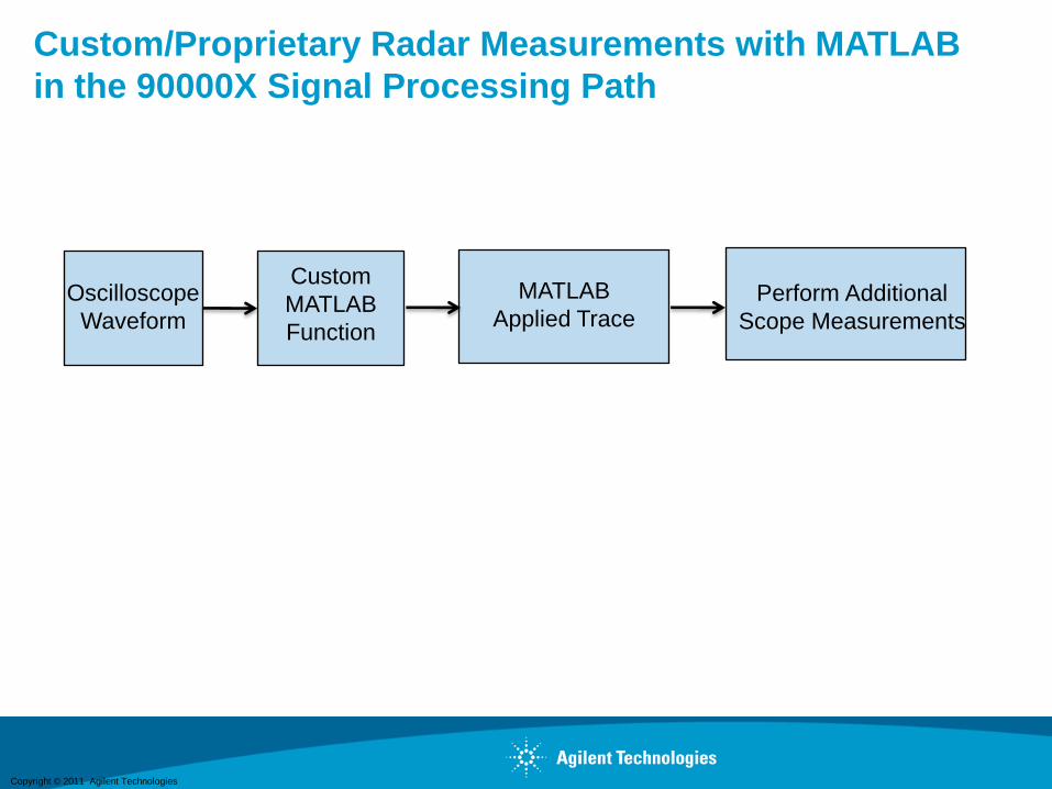
Custom/Proprietary Radar Measurements with MATLAB
in the 90000X Signal Processing Path
42
Custom
MATLAB
Function
Oscilloscope
Waveform
MATLAB
Applied TracePerform Additional
Scope Measurements
Copyright © 2011 Agilent Technologies
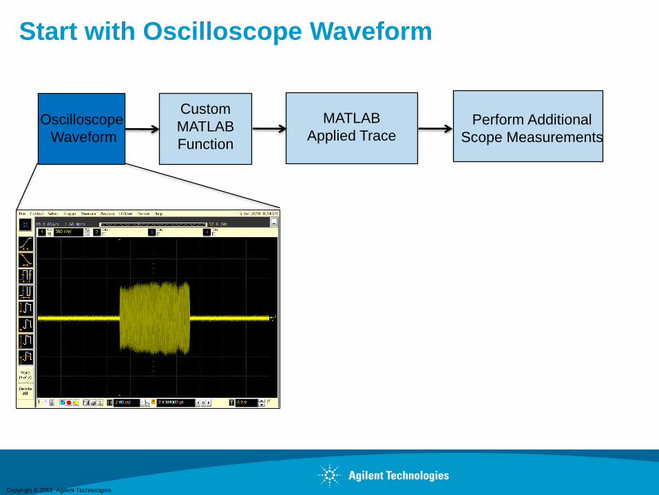
Start with Oscilloscope Waveform
43
Custom
MATLAB
Function
Oscilloscope
Waveform
MATLAB
Applied TracePerform Additional
Scope Measurements
Copyright © 2011 Agilent Technologies
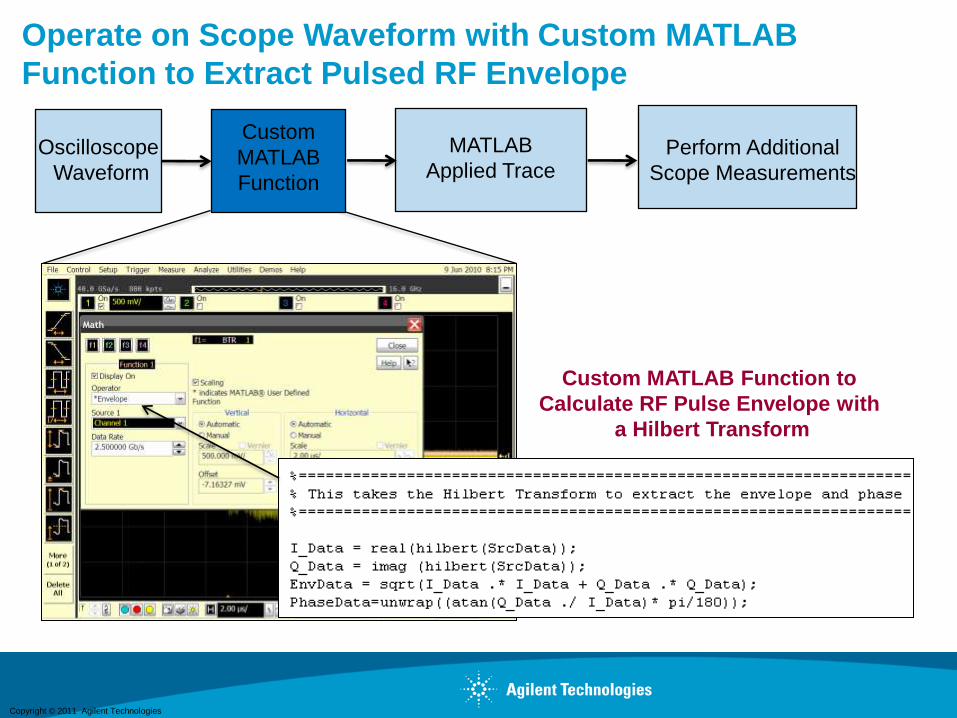
Operate on Scope Waveform with Custom MATLAB
Function to Extract Pulsed RF Envelope
44
Custom MATLAB Function to
Calculate RF Pulse Envelope with
a Hilbert Transform
Custom
MATLAB
Function
Oscilloscope
Waveform
MATLAB
Applied TracePerform Additional
Scope Measurements

Copyright © 2011 Agilent Technologies
Display the RF Pulse Envelope
45
RF Pulse Envelope
Extracted from
Custom MATLAB
Function
Custom
MATLAB
Function
Oscilloscope
Waveform
MATLAB
Applied TracePerform Additional
Scope Measurements
Copyright © 2011 Agilent Technologies
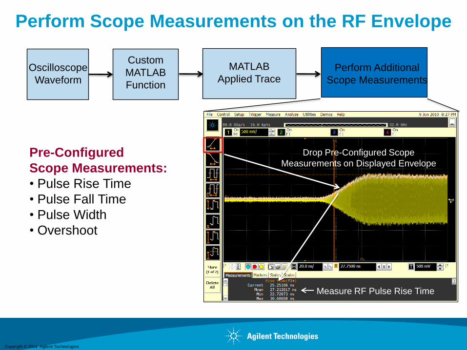
Perform Scope Measurements on the RF Envelope
46
Drop Pre-Configured Scope
Measurements on Displayed Envelope
Measure RF Pulse Rise Time
Pre-Configured
Scope Measurements:
• Pulse Rise Time
• Pulse Fall Time
• Pulse Width
• Overshoot
Custom
MATLAB
Function
Oscilloscope
Waveform
MATLAB
Applied TracePerform Additional
Scope Measurements
Copyright © 2011 Agilent Technologies
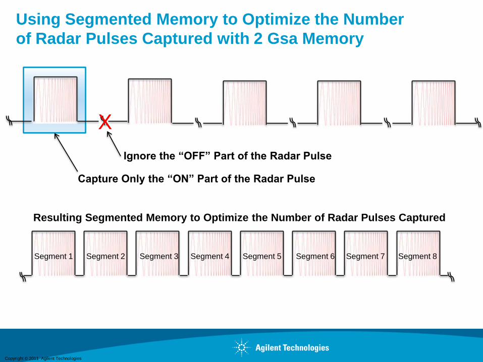
Using Segmented Memory to Optimize the Number
of Radar Pulses Captured with 2 Gsa Memory
47
Capture Only the “ON” Part of the Radar Pulse
X
Ignore the “OFF” Part of the Radar Pulse
Resulting Segmented Memory to Optimize the Number of Radar Pulses Captured
Segment 1 Segment 2 Segment 3 Segment 4 Segment 5 Segment 6 Segment 7 Segment 8
Copyright © 2011 Agilent Technologies
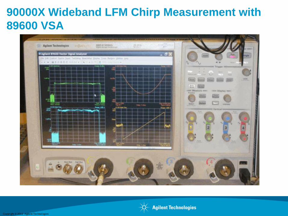
90000X Wideband LFM Chirp Measurement with
89600 VSA
48

Copyright © 2011 Agilent Technologies
Chirped Phase
Chirped
Frequency
2 GHz
Log Magnitude
Envelope Amplitude
vs. Time
LFM Chirped
Spectrum Centered
at 10 GHz
6 us
2 GHz
90000X Wideband LFM Chirp Measurement with
89600 VSA
49
Copyright © 2011 Agilent Technologies
Challenges for Radar Pulse Measurements
System level testing- characterize pulse timing for many
scenarios
Field/Flight testing is expensive- capture signals and
evaluate/characterize performance off-line
Need to evaluate a large number of pulses
Need to sort and categorize signals dependent on emitter
characteristics
50
Copyright © 2011 Agilent Technologies
Oscilloscope Signal Analyzer (OSA) Software
(preliminary)
CW and pulsed RF signal analysis for Radar/EW
Modulation domain, power, and pulse timing analysis
Application software which extends the capability of the
9000, 90000, and 90000 X-series oscilloscopes
Segmented memory capture to analyze a large number of
pulses
51
Copyright © 2011 Agilent Technologies
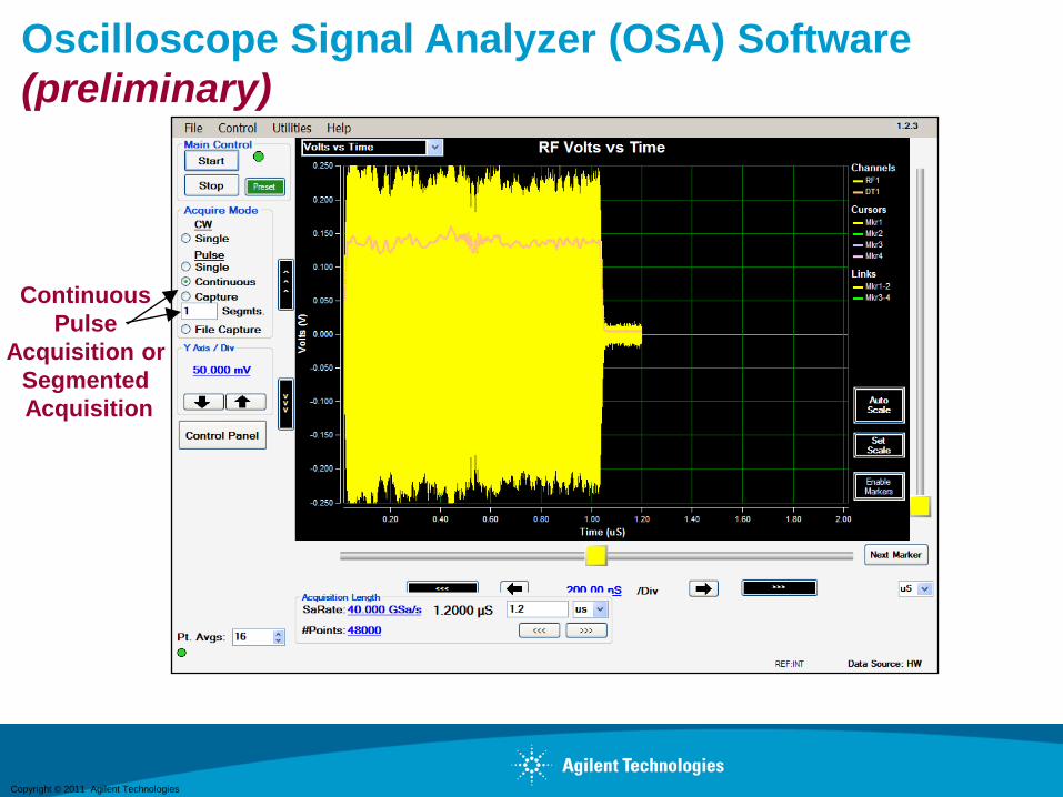
Oscilloscope Signal Analyzer (OSA) Software
(preliminary)
52
Continuous
Pulse
Acquisition or
Segmented
Acquisition
Copyright © 2011 Agilent Technologies
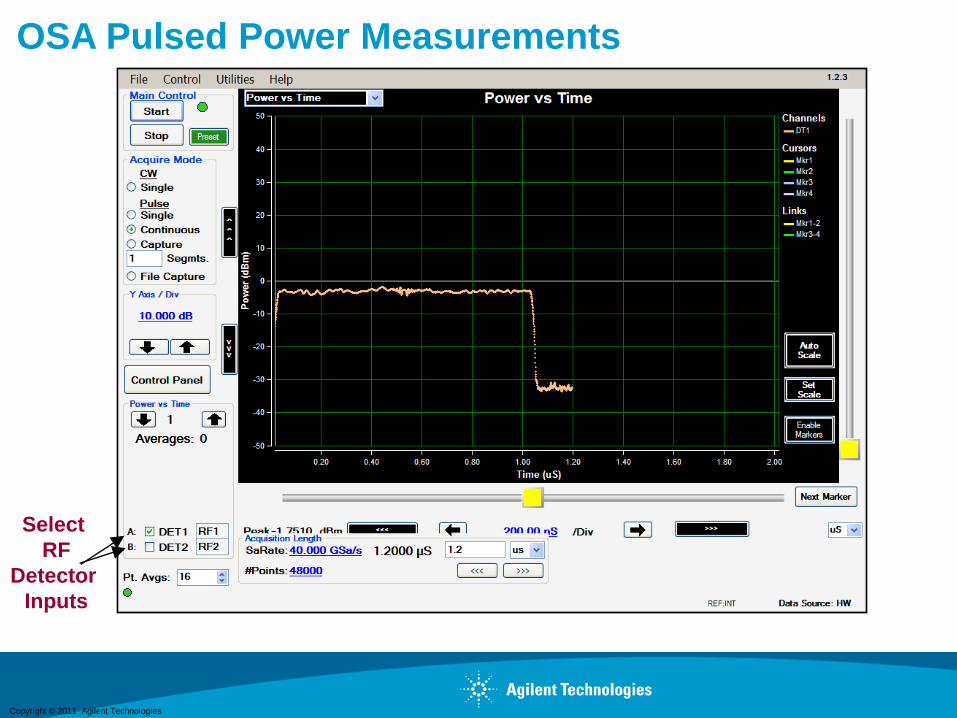
OSA Pulsed Power Measurements
53
Select
RF
Detector
Inputs
Copyright © 2011 Agilent Technologies
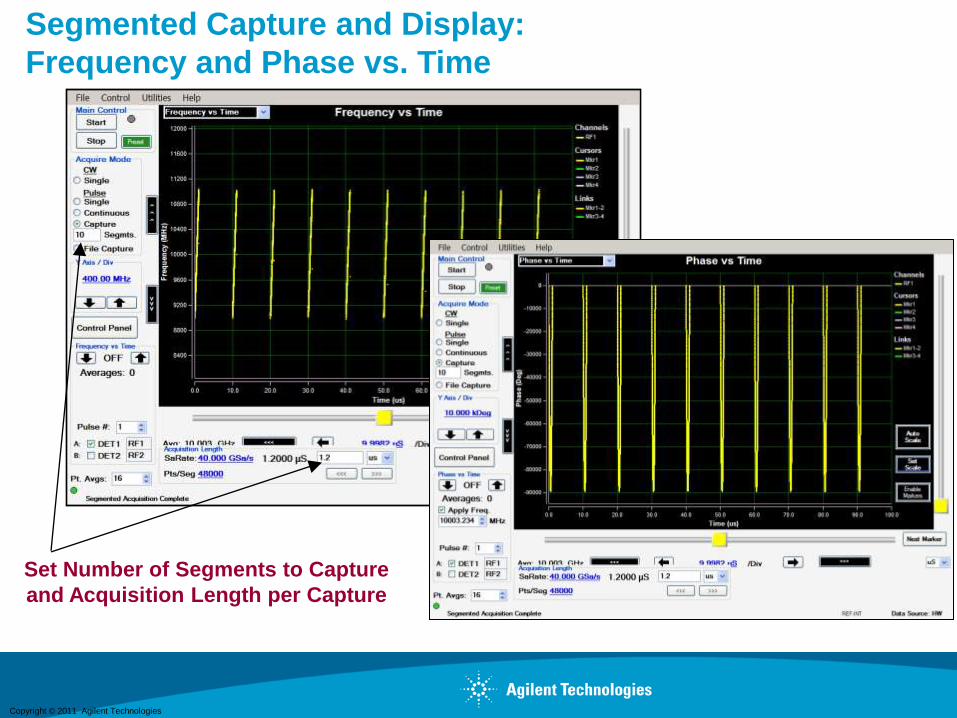
Segmented Capture and Display:
Frequency and Phase vs. Time
54
Set Number of Segments to Capture
and Acquisition Length per Capture
Copyright © 2011 Agilent Technologies
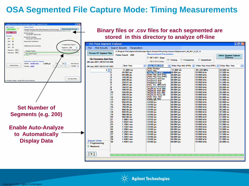
OSA Segmented File Capture Mode: Timing Measurements
55
Set Number of
Segments (e.g. 200)
Enable Auto-Analyze
to Automatically
Display Data
Binary files or .csv files for each segmented are
stored in this directory to analyze off-line
Copyright © 2011 Agilent Technologies
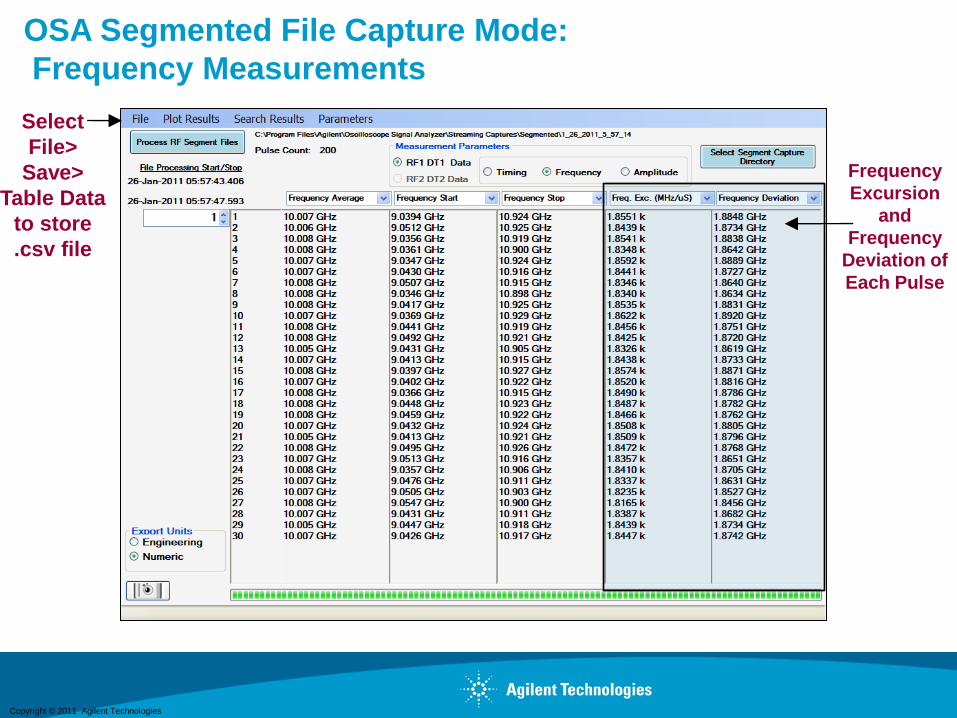
OSA Segmented File Capture Mode:
Frequency Measurements
56
Frequency
Excursion
and
Frequency
Deviation of
Each Pulse
Select
File>
Save>
Table Data
to store
.csv file
Copyright © 2011 Agilent Technologies
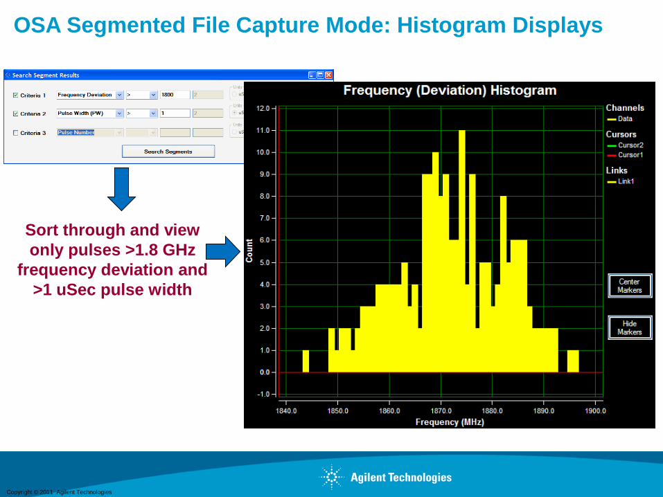
OSA Segmented File Capture Mode: Histogram Displays
57
Sort through and view
only pulses >1.8 GHz
frequency deviation and
>1 uSec pulse width
Copyright © 2011 Agilent Technologies
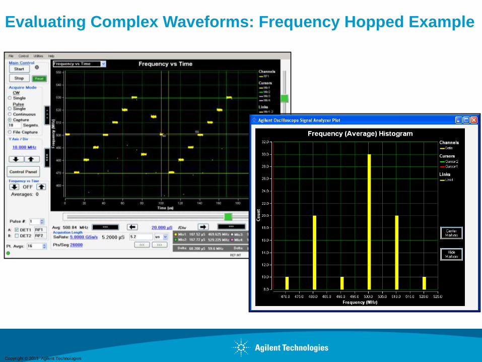
Evaluating Complex Waveforms: Frequency Hopped Example
58
Copyright © 2011 Agilent Technologies
Wideband 16QAM Example
59
Copyright © 2011 Agilent Technologies
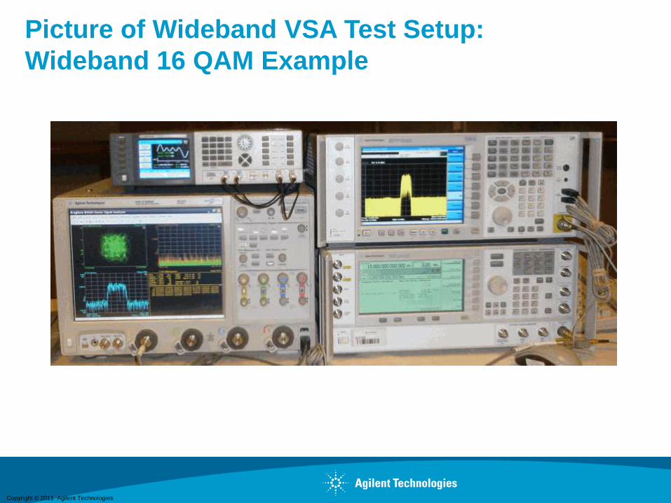
Picture of Wideband VSA Test Setup:
Wideband 16 QAM Example
60
Copyright © 2011 Agilent Technologies
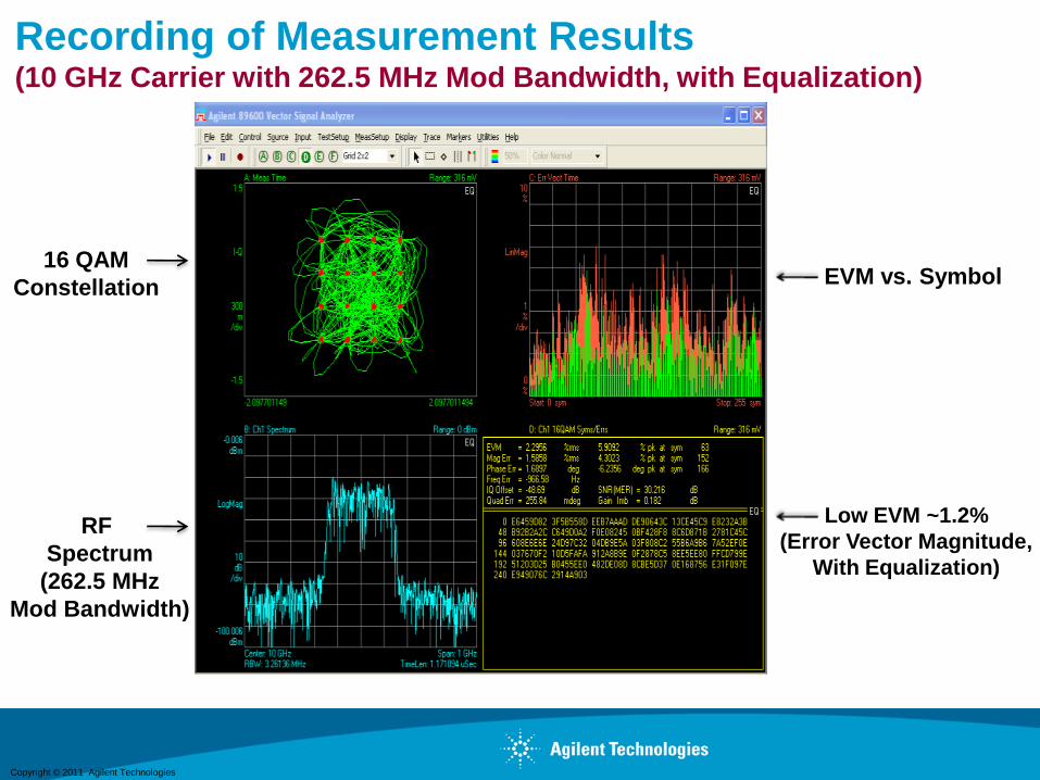
Recording of Measurement Results(10 GHz Carrier with 262.5 MHz Mod Bandwidth, with Equalization)
61
16 QAM
Constellation
RF
Spectrum
(262.5 MHz
Mod Bandwidth)
EVM vs. Symbol
Low EVM ~1.2%
(Error Vector Magnitude,
With Equalization)
Copyright © 2011 Agilent Technologies
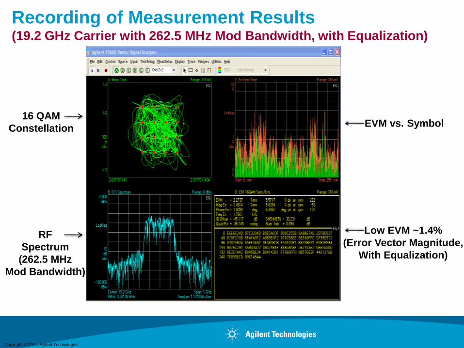
Recording of Measurement Results(19.2 GHz Carrier with 262.5 MHz Mod Bandwidth, with Equalization)
62
16 QAM
Constellation
RF
Spectrum
(262.5 MHz
Mod Bandwidth)
EVM vs. Symbol
Low EVM ~1.4%
(Error Vector Magnitude,
With Equalization)

Copyright © 2011 Agilent Technologies
Recording of Measurement Results(14.5 GHz Carrier with approx 1 GHz Mod Bandwidth, with Equalization)
63
16 QAM
Constellation
RF
Spectrum
(>1 GHz
Mod Bandwidth)
EVM vs. Symbol
Low EVM ~1.8%
(Error Vector Magnitude,
With Equalization)
Copyright © 2011 Agilent Technologies
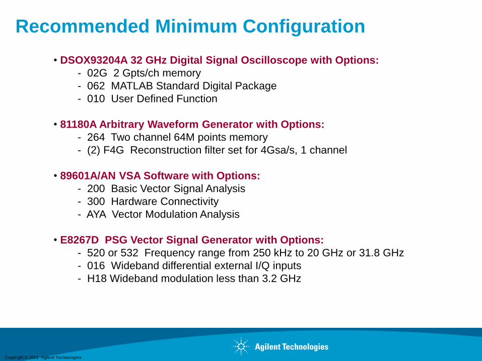
Recommended Minimum Configuration
64
• DSOX93204A 32 GHz Digital Signal Oscilloscope with Options:
- 02G 2 Gpts/ch memory
- 062 MATLAB Standard Digital Package
- 010 User Defined Function
• 81180A Arbitrary Waveform Generator with Options:
- 264 Two channel 64M points memory
- (2) F4G Reconstruction filter set for 4Gsa/s, 1 channel
• 89601A/AN VSA Software with Options:
- 200 Basic Vector Signal Analysis
- 300 Hardware Connectivity
- AYA Vector Modulation Analysis
• E8267D PSG Vector Signal Generator with Options:
- 520 or 532 Frequency range from 250 kHz to 20 GHz or 31.8 GHz
- 016 Wideband differential external I/Q inputs
- H18 Wideband modulation less than 3.2 GHz
Copyright © 2011 Agilent Technologies
Additional References
65
• http://www.agilent.com/find/oscilloscopes
• http://www.agilent.com/find/AWG
• http://www.agilent.com/find/PXA
• http://www.agilent.com/find/powerofx
• http://www.agilent.com/find/matlab_oscilloscopes

Copyright © 2011 Agilent Technologies
New Application Note:
http://www.agilent.com/find/powerofx
66

Copyright © 2011 Agilent Technologies
Summary
67
Many Radar and SatCom applications require wideband equipment to
generate and analyze custom/proprietary waveforms.
AWGs COTS Equipment and waveform creation tools let you create
Custom/Proprietary Wideband Radar and Satcom Waveforms
New Agilent Signal Analyzers can capture and analyze up to 140 MHz
instantaneous bandwidth with carrier up to 50 GHz.
90000X Oscilloscope enables you to directly measure the True Performance
of X, Ku, and Ka-Band Transmitter Outputs -- up to 32 GHz
Vector Signal Analysis software perform measurements in Time, Frequency
and Modulation domains
Perform Advanced Pulse Timing, Frequency, and Amplitude Measurements
with the OSA software

Copyright © 2011 Agilent Technologies68
BACKUP SLIDES

Copyright © 2011 Agilent Technologies
The highest measurement accuracy
So you don’t waste your jitter budget
• 32 GHz true analog bandwidth
• Industry’s lowest oscilloscope noise floor
• Lowest real-time oscilloscope measurement jitter floor
A complete 30 GHz probing system
So you get full bandwidth to the probe tip
• Fully customized probe amplifier s-parameter correction
• Upgradeable Probing System
The industry’s most accurate “RF scope”
So you can take advantage of Agilent’s RF expertise
• Analysis through the Ka band without the need for down conversion
• Full VSA performance
• Analysis built for wireless LAN, radar, satellite, and ultra wideband applications
Agilent Infiniium 90000 X-Series OscilloscopesEngineered for true analog bandwidth that delivers