add-ons for simatic pcs 7 - industrial automationtia), the simatic pcs 7 process control system is...
TRANSCRIPT

SIMATIC PCS 7
siemens.com/simatic-pcs7
Add-ons for the SIMATIC PCS 7 Process Control System
Catalog ST PCS 7 AO
Edition 2017
© Siemens AG 2017
Catalogs for Process Automation
www.siemens.com/pa-catalogs
SIMATIC ST PCS 7SIMATIC PCS 7Process Control SystemSystem components
E86060-K4678-A111-C3-7600
SIMATIC ST PCS 7 TSIMATIC PCS 7Process Control SystemTechnology components
E86060-K4678-A141-A3-7600
SIMATIC ST 70Products forTotally Integrated Automation
E86060-K4670-A101-B5-7600
SIMATIC HMI / ST 80/ST PCPC-based Automation Human Machine Interface SystemsPC-based Automation
E86060-K4680-A101-C4-7600
Industrial Communication IK PISIMATIC NET
E86060-K6710-A101-B8-7600
Process Automation FI 01Field Instruments for Process Automation
PDF (E86060-K6201-A101-C1-7600)
Process Automation AP 01Process Analytical Instruments
E86060-K3501-A101-B3-7600
Weighing Technology WT 10Products for Weighing Technology
PDF (E86060-K6410-A101-A5-7600)
SITRAIN ITCTraining for Industry
Only available in GermanE86060-K6850-A101-C5
Products for Automation and Drives CA 01Interactive CatalogDVD
E86060-D4001-A510-D7-7600
Industry Mall Information and Ordering Platformon the Internet:
www.siemens.com/industrymall
Related catalogs
© Siemens AG 2017

Information and management systems 1
Advanced Process Control 2
Operator control and monitoring 3
Libraries/blocks/tools 4
Distributed I/O on PROFIBUS 5
Diagnostics 6
Telecontrol 7
currently no contents 8
Energy management 9
Architecture and configuration 10
Appendix 11
Add-ons for the SIMATIC PCS 7 Process Control SystemSIMATIC PCS 7
Catalog ST PCS 7 AO · 2017
Supersedes:Catalog ST PCS 7 AO · 2015
Refer to the Industry Mall for current updates of this catalog:www.siemens.com/industrymalland as PDF at the following address:www.siemens.com/stpcs7ao
The products contained in this catalog can also be found in the Interactive Catalog CA 01.Article No.: E86060-D4001-A500-D7-7600
Please contact your local Siemens branch.
© Siemens AG 2017
The products and systems described in this catalog are manufactured/distributed under application of a certified quality management system in accordance with DIN EN ISO 9001 (Certified Registration No. 000656 QM08). The certificate is recog-nized by all IQNet countries.
© Siemens AG 2017

2 Siemens ST PCS 7 AO · 2017
Add-ons for SIMATIC PCS 7.
As an important component of Totally Integrated Automation
(TIA), the SIMATIC PCS 7 process control system is integrated
seamlessly in a comprehensive range of perfectly matched
products, systems, and solutions for all hierarchy levels of
industrial automation - from the enterprise management level, to
the control level, all the way down to the field level. Thus the
complete process chain at a production location can be auto-
mated, and not just the actual production process - from the
inbound logistics (material supply), through the primary process
and downstream secondary processes (filling, packaging), down
to the outbound logistics (storage).
The exceptionally powerful and versatile SIMATIC PCS 7 process control system is an ideal basis for the cost-effective imple-mentation and efficient operation of control systems. Its functionality can be expanded through the seamless integration of tech-nology components for specific automa-tion tasks.
Uniformity, modularity, flexibility, scalability, and the openness of SIMATIC PCS 7 addi-tionally provide optimal prerequisites for integrating supplementary components and solutions into the process control system in an applicative manner and thus extend and round off its functionality.
Since SIMATIC PCS 7 was launched on the market, we at Siemens as well as our exter-nal partners have developed a wide range of supplementary components which we refer to in short as PCS 7 add-on products.
© Siemens AG 2017

3Siemens ST PCS 7 AO · 2017
PCS 7 add-on products are software packages and hardware components that are optimally adapted to the respective field of application and thus enable cost-effective use of SIMATIC PCS 7 for special automation tasks.
With this catalog, we wish to help you in finding products for your specific task.
© Siemens AG 2017

4 Siemens ST PCS 7 AO · 2017
Product responsibility, conditions of use
The responsibility for a PCS 7 add-on product generally rests with the product manager in each case. The address of the product manager can be found in the "More information" section. This gives you direct access to the appropriate special-ists.
All SIMATIC PCS 7 add-on products entitle you to worldwide hotline support from our Technical Support center. Information on central technical support as well as con-tact addresses can be found in the appen-dix to this catalog; the general terms and conditions apply.
External SIMATIC PCS 7 partners organize the sale and delivery of their products in-dependently. Their own terms and condi-tions of business and delivery apply. Cor-responding information can be obtained from the addresses given in the "More information" section. Siemens AG accepts no liability and offers no warranty for the products of external SIMATIC PCS 7 part-ner companies.
The catalog contains hyperlinks to other websites or third party sources (hereinafter referred to as "sites"). Siemens does not guarantee the availability, completeness or incorrectness of these sites and disclaims any contractual and non-contractual liabil-ity, in particular for the content, goods and products that are offered on these pages. Any agreements that are made are exclu-sively between the user and the respective providers of these services at their terms and conditions.
Pricing information
Pricing information for the products with article numbers in this catalog can be obtained via the interactive catalog CA 01, the Industry Mall on the Internet, or on request from your local Siemens partner.
Pricing information for the products without an article number can be provided on re-quest by the responsible add-on partners listed under "More Information".
Internet
The ST PCS 7 AO catalog can also be downloaded as a PDF file from the Informa-tion and Download Center via the Internet:www.siemens.com/stpcs7ao
Additional information is available on the SIMATIC PCS 7 web site on the Internet at:www.siemens.com/simatic-pcs7
Marking for SIMATIC PCS 7 V8
The add-on products offered in this catalog are specified for SIMATIC PCS 7 versions 7.1, 8.0, 8.1 and 8.2. SIMATIC PCS 7 versions prior to V7.0 are no longer supported by this catalog.
The possible application is specified for each product. When V8 is specified, it refers to all 8 versions, Unless the version is explicitly defined, e.g. V8.2.
© Siemens AG 2017

Siemens ST PCS 7 AO · 2017
11/2 PIMS-PCS 7-CONNECT:
Working together with PIMS systems
1/4 PCS 7 OCS: Open interface for connection ofthird-party applications
1/6 PLSDOC: Documentation updating system
1/8 ACRON 8: Long-term archiving and logging
1/9 versiondog: Data management
Information and management systems
© Siemens AG 2017

1/2 Siemens ST PCS 7 AO · 2017
1
Information and management systems
PIMS-PCS 7-CONNECT: Working together with PIMS systems
■ Overview
The products described here (interfaces and tools) support eco-nomic cooperation between SIMATIC PCS 7 including SIMATIC BATCH and the following plant information management sys-tems (PIMS):• PI-System from OSIsoft (PI PCS 7-CONNECT)• aspenOne from AspenTech (aspenOne PCS 7-CONNECT)
A plant information management system is suitable for:• Short-term and long-term archiving beyond the limits of
companies and plants• Evaluation and presentation of process and production data
The interfaces and tools provide the best possible combination of PI-System and aspenOne with SIMATIC PCS 7. They feature high flexibility, performance and safety. They also support redundant systems and archive recovery concepts, e.g. in the event of interferences in a connection.
We can additionally offer tailored, scalable support and services for efficient implementation and maintenance of these interfaces and tools. Information on support and services as well as manu-facturer declarations are available on request (for contact ad-dress, see "Further information").
High-availabilityautomationsystems
Safety-orientedautomationsystems
Standardautomationsystems
Industrial Ethernet, single/redundant
OS / Route Controlserver
Batch/archiveserver
PIMS server
PIMS interface with Connect Tools
Terminal bus, single/redundant
OS / Batch / Route Control Clients
Engineeringstation
OS single station
SAP
G_P
CS
7_X
X_0
0174
Ethernet
Office LAN (Ethernet)
© Siemens AG 2017

1/3Siemens ST PCS 7 AO · 2017
1
Information and management systems
PIMS-PCS 7-CONNECT: Working together with PIMS systems
■ Function
PI-PCS 7-CONNECT
Interface PI-CONNECT OPC+
PI-CONNECT OPC+ reads the process variables cyclically from SIMATIC PCS 7 and saves these in the PI long-term archive.
The interface is operated on a separate interface PC on the terminal bus of the SIMATIC PCS 7 process control system, and supports:• Redundancy functionality of the SIMATIC PCS 7 OS server• Concurrent time stamp treatment• Archive recovery• Failover online
The PI-CONNECT OPC+ interface can be used in combination with SIMATIC PCS 7 V7.1, V8.0, V8.1 and V8.2. It can use the following interfaces for communication with SIMATIC PCS 7:• OpenPCS 7 interface• OPC DA and OPC HDA interface (OPC UA in preparation)
Interface PI-CONNECT ALARM
The PI-CONNECT ALARM interface can be used to transfer messages from the SIMATIC PCS 7 process control system and/or other sources to the PI archive. The PI-CONNECT ALARM in-terface is characterized by the fact that all messages and alarms are detected even in exceptional situations. In addition, various recovery methods are available.
PI-CONNECT ALARM can be used together with SIMATIC PCS 7 V7.1, V8.0, V8.1 and V8.2.
PI-CONNECT SIMATIC BATCH interface
This interface transmits data from SIMATIC BATCH to the PI-Batch subsystem. Together with the PI-CONNECT OPC+ in-terface, reports and evaluations based on batch data and pro-cess data can be implemented in the PI system. Additional fea-tures of PI-CONNECT SIMATIC BATCH include:• Archive recovery• Support of hierarchical recipes of SIMATIC BATCH
PI-CONNECT SIMATIC BATCH can be used together with SIMATIC BATCH V7.1, V8.0, V8.1 and V8.2.
PI-CONNECT CONFIG tool
PI-CONNECT CONFIG can work together with PI-CONNECT OPC+ as well as with the OPC interface of OSIsoft. The tool pro-vides support for efficient creation and easy updating of the PI system project for the SIMATIC PCS 7 interface. It provides CSV files for import into the PI configuration database. It can be used equally for initial configuration of the PI system as well as for tracking SIMATIC PCS 7 configuration changes in the PI system.
PI-CONNECT CONFIG can be used together with SIMATIC PCS 7 V7.1, V8.0, V8.1 and V8.2.
aspenONE-PCS 7-CONNECT
Batch.21-CONNECT SIMATIC BATCH interface
This interface transmits data from SIMATIC BATCH to the Batch.21 system and supports you with functions such as ar-chive recovery. Thus reports and evaluations based on batch data and process data can be implemented in the AspenTech system.
Batch.21 CONNECT SIMATIC BATCH can be used together with SIMATIC BATCH V7.1, V8.0, V8.1 and V8.2.
Interface IP.21-CONNECT RECOVERY
Servers disconnections when fetching data from OPC DAservers can sometimes lead to gaps. These data gaps are preventable with the IP.21-CONNECT RECOVERY interface. Missing data can be read from the OPC HDA server of the process control system.
The IP.21-CONNECT RECOVERY interface provides two recovery mechanisms:• Manual recovery with specification of the time period• Automatic recovery (for closing the data gaps before starting
the OPC DA interface)
The IP.21-CONNECT RECOVERY interface is suitable for use with SIMATIC PCS 7 V7.1, V8.0, V8.1 and V8.2.
IP.21-CONNECT CONFIG tool
IP.21-CONNECT CONFIG provides support for effective creation and easy updating of the IP.21 system project for the SIMATIC PCS 7 link. The tool provides CSV files for importing into the IP.21 configuration database. It can be used equally for initial config-uration of the IP.21 system and for tracking SIMATIC PCS 7 con-figuration changes in the IP.21 system.
IP.21-CONNECT CONFIG can be used together with SIMATIC PCS 7 V7.1, V8.0, V8.1 and V8.2.
■ More information
Siemens AGSiemens GermanyProcess Industries and DrivesSolution OperationMannheim branch
Tel.: +49 621 456-3315Fax: +49 621 456-3334
E-mail: [email protected]
You can find additional information on the Internet at:www.siemens.de/mis-pcs7
© Siemens AG 2017

1/4 Siemens ST PCS 7 AO · 2017
1
Information and management systems
PCS 7 OCS: Open interface for connection of third-party applications
■ Overview
As an alternative to the OpenPCS 7 system interface, the PCS 7 OCS open data interface can also be used for data communication between external systems on the MES and ERP levels and the SIMATIC PCS 7 process control system.
In contrast to the Open PCS 7 interface based on OPC specifi-cations, the PCS 7 OCS interface uses a platform-independent communication standard (ACPLT/KS), which enables stable, firewall-compatible TCP/IP communication over configurable, fixed network ports.
The server interface PCS 7 OCS offers functions for reading and writing process tags as well as for reading out message archives and the process value archive of the process control system SI-MATIC PCS 7. This allows e.g. job, production, or inventory infor-mation to be exchanged, visualized, and edited between an ERP system (Enterprise Resource Planning) and SIMATIC PCS 7.
In addition to the process and archive data, structure and type information of the process control system configuration can be read out via the PCS 7 OCS server interface. External applica-tions can therefore be used to systematically search through the process control system SIMATIC PCS 7 according to various cri-teria (e.g. search all function blocks of type "CTRL_PID" and read the actual value of the manual/automatic parameter "AUT_ON_OP").
Note:
PCS 7 OCS can be used together with SIMATIC PCS 7 V7.1, V8.0, V8.1 and V8.2.
■ Application
Easy integration of external applications/systems to SIMATIC PCS 7, including:• SAP and other ERP systems from the corporate management
level• MES systems for production management• PIMS (Plant Information Management Systems) to gather
operating data• Simulation and optimization tools, e.g. for monitoring of
controller performance or for application of Advanced Process Control
• Analysis tools for alarm management• External database applications for long-term archiving and
data analysis for more than a single plant• Web browser for presentation of production information
(online data, message lists, trends, dashboards)• Generation of reports, e.g. with Microsoft Excel• Data exchange between SIMATIC PCS 7 and process control
systems from other manufacturers
■ Design
PCS 7 OCS is installed directly on the PCS 7 OS server. Neither additional hardware nor any special configuration of the associ-ated OS server is necessary.
Two PCS 7 OCS licenses are required for connecting redundant couplings, one for each OS server of a redundant pair of serv-ers. Identical information is then available redundantly via the two PCS 7 OCS interfaces of this pair of servers.
Powerful PCS 7 OCS communication based on the TCP/IP pro-tocol for data communication between an OS server and exter-nal application/system is also possible without problems in dis-tributed networks in which the access is limited by means of a firewall.
Process values, process value archives
and messages
SQL database
SIMATIC PCS 7 plant bus
OS server
MES PIMS
Microsoft Excel
Web MATLAB Simulink
ERP SAP
LAN
PCS 7 OCS
PCS 7 AS
PCS 7 AS
PCS 7 AS
G_P
CS7
_XX_
0001
3
© Siemens AG 2017

1/5Siemens ST PCS 7 AO · 2017
1
Information and management systems
PCS 7 OCS: Open interface for connection of third-party applications
■ Function
• Access to the tag management of an OS server (read and sometimes also write)
• Reading structure and type information• Reading out process value archives (Tag Logging)• Reading out the alarm log (Alarm Logging)
Additive standard applications from LeiKon GmbH
LeiKon GmbH offers the following applications for the SIMATIC PCS 7 connection via PCS 7 OCS in addition to the PCS 7 OCS (server interface) (see under "More information" for the contact address for detailed information and ordering):• Intexc SUITE,
a software platform for operating assistance systems to allow anticipatory and proactive operation in the following appli-cation areas:- Soft sensors- Process prediction- Optimized control- Online quality control- Status-based maintenance- Performance indexes
• Intexc CONNECT,a data coupler between SIMATIC PCS 7 and external applications/systems:- SAP systems- Process data archives and data bases
• Intexc AUTO CONFIG,a tool for rule-based query and evaluation of process and configuration data with the following application options:- Bulk engineering and continuous consistency adjustment of
operating data acquisition systems (PIMS) with the data point configuration of SIMATIC PCS 7
- Automatically generated reports for monitoring and documentation of plant and process conditions
- System-independent reverse documentation and validation of SIMATIC PCS 7 configurations for acceptance (SAT, FAT)
■ Ordering data Article No.
■ More information
LeiKon GmbHKaiserstr. 10052134 HerzogenrathGermany
Tel.: +49 2407 95 17 330Fax: +49 2407 95 17 339
E-mail: [email protected]
Additional information is available on the Internet at:
www.leikon.de
SIMATIC PCS 7 OCS V3.3 incl. SP1Open communication server for data exchange between SIMATIC PCS 7 OS server and third-party system/application, runs with SIMATIC PCS 7 V7.1, V8.0, V8.1 and V8.2, single license for 1 installation
Engineering software with runtime license for one PCS 7 OS server, one language (German), software class B
Delivery package: Software and documentation on CD and certifi-cate of license
6DL5405-8AD33-0XA0
Additive applicationsFor data communication with the SIMATIC PCS 7 OS server via SIMATIC PCS 7 OCS, e.g. Intexc (www.intexc.de)
On request from LeiKon GmbH
© Siemens AG 2017
1/6 Siemens ST PCS 7 AO · 2017
1
Information and management systems
PLSDOC RE: Documentation updating system
■ Overview
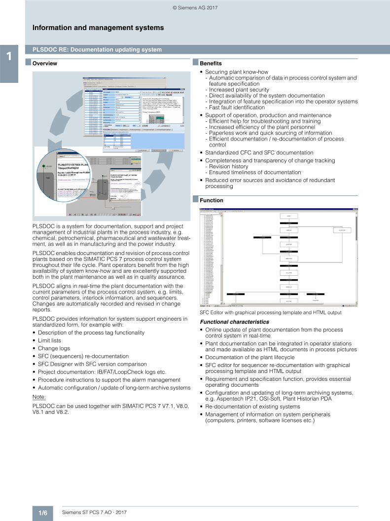
PLSDOC is a system for documentation, support and project management of industrial plants in the process industry, e.g. chemical, petrochemical, pharmaceutical and wastewater treat-ment, as well as in manufacturing and the power industry.
PLSDOC enables documentation and revision of process control plants based on the SIMATIC PCS 7 process control system throughout their life cycle. Plant operators benefit from the high availability of system know-how and are excellently supported both in the plant maintenance as well as in quality assurance.
PLSDOC aligns in real-time the plant documentation with the current parameters of the process control system, e.g. limits, control parameters, interlock information, and sequencers. Changes are automatically recorded and revised in change reports.
PLSDOC provides information for system support engineers in standardized form, for example with:• Description of the process tag functionality• Limit lists• Change logs• SFC (sequencers) re-documentation• SFC Designer with SFC version comparison• Project documentation: IB/FAT/LoopCheck logs etc.• Procedure instructions to support the alarm management• Automatic configuration / update of long-term archive systems
Note:
PLSDOC can be used together with SIMATIC PCS 7 V7.1, V8.0, V8.1 and V8.2.
■ Benefits
• Securing plant know-how- Automatic comparison of data in process control system and
feature specification- Increased plant security- Direct availability of the system documentation- Integration of feature specification into the operator systems- Fast fault identification
• Support of operation, production and maintenance- Efficient help for troubleshooting and training- Increased efficiency of the plant personnel- Paperless work and quick sourcing of information- Efficient documentation / re-documentation of process
control• Standardized CFC and SFC documentation• Completeness and transparency of change tracking
- Revision history- Ensured timeliness of documentation
• Reduced error sources and avoidance of redundant processing
■ Function
SFC Editor with graphical processing template and HTML output
Functional characteristics• Online update of plant documentation from the process
control system in real-time• Plant documentation can be integrated in operator stations
and made available as HTML documents in process pictures• Documentation of the plant lifecycle• SFC editor for sequencer re-documentation with graphical
processing template and HTML output• Requirement and specification function, provides essential
operating documents• Configuration and updating of long-term archiving systems,
e.g. Aspentech IP21, OSI-Soft, Plant Historian PDA• Re-documentation of existing systems• Management of information on system peripherals
(computers, printers, software licenses etc.)
© Siemens AG 2017

1/7Siemens ST PCS 7 AO · 2017
1■ Function (continued)
Information and management systems
PLSDOC RE: Documentation updating system
Technology
System overview of PLSDOC
• Central, database-driven plant documentation- Generation of HTML documents for every process variable- Referencing of other process variables can be directly called
using hyperlinks• Coupling of SIMATIC PCS 7 and SIMATIC WinCC as well as
connection of control systems / controllers of any kind via OPC, e.g. Delta V, Freelance, 800xA
• Special solutions for legacy systems such as TELEPERM M, Contronic P, Advant Master
• Monitoring of redundant pairs of servers during re-documen-tation and switchover to the redundant server upon failure of the active server
• Buffering the change information prevents data loss due to connection interruptions between OS server and PLSDOC
• Plant-wide application• Menu-guided installation by the user possible
Application computer- PLSDOC front end- PLSDOCTracker for scanning of OPC gateway, communication with database- Memory location PLSDOC- Memory location Support&Help for access of the OS
OPC gatewayMonitoring of OPC variables for changes
Terminal bus(Industrial Ethernet)
PLSDOCdatabase
Operator station
Engineeringstation
Redundant OS server
SCALANCE X
G_P
CS
7_X
X_0
0149
■ Technical specifications
System requirements• Microsoft Windows XP, Windows Vista, Windows 7,
Windows 8; 32-bit or 64-bit in each case• Microsoft Windows Server 2003, 2008, 2008 R2, 2012; 32-bit
or 64-bit in each case
Application computer• 2 GB RAM, 5 GB hard disk
Database computer• Microsoft SQL Server 2005, 2008, 2008 R2, 2012• 4 GB RAM, 100 GB hard disk
■ More information
iMes Solutions GmbHElisabethstr. 884489 BurghausenGermany
Tel.: +49 8677 96180
E-mail: [email protected]
You can find additional information on the Internet at:www.imes-solutions.com
© Siemens AG 2017

1/8 Siemens ST PCS 7 AO · 2017
1
Information and management systems
ACRON 8: Long-term archiving and logging
■ Overview
The ACRON system, based on a rugged, fault-tolerant client-server architecture, is designed for the factory-wide, cross-plant and long-term archiving of operating data as well as its analysis, interpretation and indelible logging. It provides the plant opera-tor with excellent support for plant optimization and energy mon-itoring (according to DIN ISO 50001) and for the fulfillment of re-porting obligations.
Originally designed for the special requirements of environmen-tal engineering, ACRON has since become widely accepted in many other sectors including water & wastewater (DWA-M 260, DWA-A 216), chemicals, pharmaceuticals (21 CFR Part 11 stan-dard of the Food and Drug Administration), food, oil & gas.
ACRON is also suitable for meeting the high requirements en-countered in the water/wastewater/environmental industry with regard to acquisition, display, analysis and documentation of op-erating data, for example, the ATV M260 guideline in Germany.
The current ACRON 8 version offers an exceptional price/perfor-mance ratio, and is impressive in operation thanks to high avail-ability, running reliability, and data integrity. Simple configura-tion, easy handling and high flexibility are further exceptional features.
■ More information
VIDEC Data Engineering GmbHContrescarpe 128203 BremenGermany
Tel.: +49 421 339500Fax: +49 421 3379561
E-mail: [email protected]
You can find additional information on the Internet at:www.acron8.com
■ Design
The modular, scalable ACRON 8 can be individually configured to match the size and requirements of the project – as a single-user system, as a networked client-server system or also as a multi-server. It is available in German and English (further imple-mented languages on request).
The following modules are components of ACRON 8:• Database:
More than 250 000 data points, time-based or change-dependent recording, arithmetic operations, high perfor-mance with resolution in the millisecond range, high data security due to TLC (Three Level Cache)
• Provider: Data acquisition from any sources with telecontrol link and very high data security and optional time stamp transfer; data transfer from various measuring instruments
• Reporter:Convenient operator interface for printing of reports and logs with input facility for manual laboratory values
• Graph:User-friendly presentation and analysis of measured values and statistical values in trends
• Fault and maintenance module:Generation of all required fault and message reports as well as comprehensive statistics
• AC Job:Administration module for automatic printing of reports including sending by e-mail
• AC Mirror: Up to 6-fold database redundancy
• JUNE5 as ACRON Web front end
Interfaces tailored to SIMATIC PCS 7 allow seamless integration with the process control system. Some modules can be inte-grated as OCX in SIMATIC PCS 7. A web application (Pure Web) and a Microsoft Excel add-in are also available.
Graphs and reports can be displayed on any hardware platform with common browsers using JUNE5 as a pure web front-end without plug-ins. The web application can be operated as a por-tal, has its own login, is multi-client capable and supports simul-taneous access to multiple ACRON applications. Manual value input is also implemented.
Administration and project management
Data management Compression
Provider
• Configuration• Process values• Laboratory values
• Calculations• Compressed data
Web application
Microsoft Excel add-in
Interfaces Telecontrol
OPC, OPCUA, DDE, CSV, TXT, ODBC, SQL
SIMATIC PCS 7
Designer Reporter Graph Alarm Service
© Siemens AG 2017

1/9Siemens ST PCS 7 AO · 2017
1
Information and management systems
versiondog: Data management
■ Overview
Data management of a SIMATIC PCS 7 plant with versiondog
Siemens Solution Partner AUVESY GmbH & Co. KG (AUtomated VErsioning SYstems) offers "versiondog", a high-performance software and data management system, which can be seam-lessly integrated in to any SIMATIC PCS 7 architecture as a SIMATIC PCS 7 add-on product.
versiondog ensures data transparency and project security, helps to avoid risks and reduce overhead. It meets the require-ments for information security of aspects such as data confiden-tiality, data integrity, data availability and data authenticity.
The operator of a SIMATIC PCS 7 plant can versiondog to de-velop strategy for data management and thus operate more effi-ciently and far-sighted. With a cyclic backup, there is a check to determine whether the SIMATIC PCS 7 project currently being used corresponds to the validated software version. Cyber at-tacks can also be identified by comparing online and offline data.
Since failures of a plant usually cannot be predicted, versiondog keeps a fresh backup of SIMATIC PCS 7 project as a backup strategy in case of trouble (Disaster Recovery). This data backup is continually updated and versioned, i.e. the previous version is replaced by a new version after changes (adaptations or improvements) are made.
Audits of SIMATIC PCS 7 systems and associated automation components are optimally supported by the version control and change documentation from versiondog (reports and automatic audit trail included). SFC and CFC standard library management provides a reference for SFCs/CFCs and blocks originating from libraries.
Note:
The software and data management system, versiondog, can be used together with SIMATIC PCS 7 V7.1, V8.0, V8.1 and V8.2.
■ Application
The SIMATIC PCS 7 add-on, versiondog, can be used by the op-erator of a SIMATIC PCS 7 plant for the following tasks:• Performing all data backups and managing software versions
throughout the entire lifecycle of the SIMATIC PCS 7 plant• Cyclical check of the validated version through automatic data
backup and comparison of the saved version to the most recently released, stored version
• Mapping of the entire configuration of a SIMATIC PCS 7 system including the change history from commissioning to the current time of the plant operation
• Comparison of the SFCs and CFCs of two versions of a SIMATIC PCS 7 project using "SmartCompare" (all differences are highlighted in color and can be selected)
• Complete documentation of changes in a SIMATIC PCS 7 project, for example, audits, validations and certifications
• Version control of the software for immediate recovery in case of problems (disaster recovery)
• Restoration of optimized software versions
■ Design
The versiondog software and data management system is based on a client-server architecture. As client-server system, versiondog can be installed in the network of a SIMATIC PCS 7 plant on a dedicated server or directly on a SIMATIC PCS 7 en-gineering station (ES). Alternatively, the client can operate alone on the engineering station (no server connection and no check-in/check-out).
The client, which can also be run without installation (or rights management), does not carry out any write operations on Windows directories or read/write operations on the Windows registry. System administration is thus possible from any PC-based station. Warranty claims against system suppliers are not voided.
Therefore, versiondog can also very easy integrated in a SIMATIC PCS 7 plant without additional drivers and special setting or configuration in the SIMATIC PCS 7 project.
Aut
omat
ed b
acku
p
Backup · Versioning · Documentation
Dow
nload
Check-In
Check-Out
Server Client
© Siemens AG 2017

1/10 Siemens ST PCS 7 AO · 2017
1
Information and management systems
versiondog: Data management
■ Function
Data comparing two versions of a SIMATIC PCS 7 project using SmartCompare from versiondog
Data management functions• Central data storage
Server-based data storage with clear SIMATIC PCS 7 project structure, user and access management as well as protection against inadvertent overwriting
• Version management with audit trail of versiondog:Version management and documentation with logging of all changes as proof of WHO, WHEN, WHAT and WHY; visual-ization of changes by means of comparative graphic display for CFC/SFC blocks and charts
• SIMATIC PCS 7 SmartCompare:Comparator and synchronization modules for alignment of different project versions with clear representation of differ-ences (as graphics, table or text)
• Automatic data savingCyclic, automatic data saving of engineering stations, automation systems and operator stations
• Synchronization with server versionGuaranteed use of the most recent version saved on the server in the plant
Functions of library management• Reference for built and used SFCs/CFCs and blocks,
available as a standalone client and as a report• Automatic check for actuality in the current project
- Green: Project and library are the same- Yellow: Library is newer than project- Red: Project does not correspond to any version of the
library• Alarm function for unauthorized modification of standard
charts
Library management for SIMATIC PCS 7 projects with versiondog
Cyber security functions• Cyclic, automatic verification that the released version actually
controls the production unchanged:- Several times daily- With alarm indication- For textual and/or graphic representation of the differences
when there are discrepancies- For nearly all components of the automation system
• Assurance that version levels cannot be changed. (Versions cannot be manipulated)
• Restoring a version without "contamination"• Check for the authorization of versioning in connection with an
RMS (Requirement Management System); versioning is possible for fulfillment of the RMS requirement profile
• Monitoring of the system configuration of Windows and Linux-based systems
■ More information
AUVESY GmbH & Co KGFichtenstr. 38 B76829 LandauGermany
Tel.: +49 6341 6810-400Fax: +49 6341 6810-311
E-mail: [email protected]
You can find additional information on the Internet at:www.versiondog.com
© Siemens AG 2017

Siemens ST PCS 7 AO · 2017
22/2 INCA MPC:
Model-predictive multi-variable controller
2/3 INCA Sensor: Soft sensors for non-measurable quality variables
2/5 INCA PID Tuner: Expert tool for the optimization of PID controllers
2/6 ADCO: Adaptive controller
Advanced Process Control
© Siemens AG 2017

2/2 Siemens ST PCS 7 AO · 2017
2
Advanced Process Control
INCA MPC: Model-predictive multi-variable controller
■ Overview
Multi-variable controller with integrated optimization procedure
Common control concepts in the process industry today are still almost exclusively based on PID controllers and also include manual intervention by the plant operator. In processes with complex dynamics, linked process variables or limitations, PID controllers reach their limit.
Additional weak spots are product or load changes which are generally carried out partly or completely by the plant operator. This causes variations which prevent optimum quality being maintained at all times.
However, if a process is to be operated close to the capacity limit, while at the same time minimizing waste and assuring the required quality, consideration of these precise boundary condi-tions in the controller strategy is absolutely essential.
By carefully applying advanced modern control procedures (Advanced Process Control, APC), the process industry has real leverage available for reducing costs and increasing quality. Advanced Process Control establishes process optimization as a link between the planning and scheduling functions of the execution level as well as the process control functions of the control level.
Of all the modern control procedures, Model Predictive Control (MPC) has emerged as the most suitable approach in numerous applications. MPC simplifies the handling of complex plant dy-namics, permits the early elimination of faults, takes into consid-eration the plant limitations, and allows complex process control strategies.
INCA MPC
This procedure is also used by INCA MPC, a multi-variable con-troller of the latest generation. INCA MPC differs from classic MPC controllers due to a series of functional extensions. Modern modeling methods, automatic step test and modeling methods, bumpless switching between different models (multi-model han-dling), expansions for batch process optimization, non-linear predictions, and a high quality of control are setting new stan-dards and enable the control of non-linear processes as well as plant-wide optimization.
A web-based INCA MPC, available since July 2015, significantly reduces the time required for implementation and can handle stricter IT security rules.
The INCA MPC software itself runs on a separate PC/server with Windows 7, Windows 8 or Windows 10 operating systems.
Note:
INCA MPC can be used together with SIMATIC PCS 7 V7.1, V8.0, V8.1 and V8.2. In SIMATIC PCS 7 V8.2, INCA MPC or INCA Sensor can be integrated via the APC (advanced process control) coupling module of the SIMATIC PCS 7 Industry Library as of V8.2 Update 1.
■ Application
Application examples of INCA MPC• Ammonia, urea, nitric acid, granulates, and phosphoric acid
plants- Increase in throughput, for example, by up to 2% for
ammonia and up to 5% for urea- Increase in steam export by up to 1% (ammonia)- Reduction in specific energy consumption by up to 2%- Increased plant availability- Lower sensitivity to changes in condition of supplied gas
(ammonia)• Distillation towers
- Operation closer to the concentration restrictions- Reduction of steam consumption- Operation within a performance range of large bandwidth
(from technical minimum up to full-load)• Specific solutions for the glass industry based on INCA MPC
technology, e.g. custom-designed solutions for melting tanks, glass channels and glass tubes
• Batch plants (non-linear version of INCA MPC)- Proven reduction in response time (dead time) by up to 20%
■ More information
IPCOS
Tel.: +32 1639 3083Fax: +32 1639 3080
E-mail: [email protected]
Additional information is available on the Internet at:
www.ipcos.com
Approach limitations closer with setpoints
with MPCwithout MPClimitation
∆=Profit
G_P
CS
7_X
X_0
0021
© Siemens AG 2017

2/3Siemens ST PCS 7 AO · 2017
2
Advanced Process Control
INCA Sensor: Soft sensors for non-measurable quality variables
■ Overview
Online determination of quality variables
Production plants in the process industry today rely on regular and extremely time-consuming laboratory analyses for quality control purposes (new measured values typically every 8 to 24 hours). Or they use very expensive and high-maintenance online analyzers (new values typically every 20 to 60 minutes). In order to raise productivity and run the process up to its full ca-pacity while maintaining the required quality, it is necessary to measure product quality online with a refresh rate of between 0.5 and 3 minutes. This ensures that the controller responds at the right time and the product specifications are maintained.
The plant operator is usually responsible for complete or partial process control. Weak points in process control are also reflected by changes in product quality or in the utilization of production capacity. Since no quality values are known during a conversion, the production specifications do not correspond to the quality requirements over longer periods.
These problems can be solved by using soft sensors. Soft sensors are calculation procedures which determine non-measurable quality variables on the basis of measurable pro-cess values (pressures, flow rates, temperatures, levels, etc.)in cycles of between 0.5 and 3 minutes. The calculation is made on the basis of a (non-)linear parametric model generated from historic plant data or through dedicated tests. The high-speed soft sensor predictions can be consolidated by laboratory anal-yses or values from online analyzers.
The soft sensor predictions enable the frequency of laboratory analyses and the use of online analyzers to be reduced. They raise product quality while at the same time reducing operating costs.
INCA Sensor is a tool for designing, parameterizing and operat-ing soft sensors. It makes it easier to master complex plant dy-namics, and enables operating conditions to be optimized so that the quality of the end product is assured.
Note:
INCA Sensor can be used together with SIMATIC PCS 7 V7.1, V8.0, V8.1 and V8.2. In SIMATIC PCS 7 V8.2, INCA MPC or INCA Sensor can be integrated via the APC (advanced process control) coupling module of the SIMATIC PCS 7 Industry Library as of V8.2 Update 1.
Process variablesTemperaturesPressuresLevelsFlow rates(every 0.5 ... 3 min)
Non-linear parametric model
To the closed-loop control system
Consolidation/compensationand updating
Quality variablesDensitiesConcentrationMelt IndexesViscosities(every 8 ... 24 hrs)from laboratory
Quality variablesDensitiesConcentrationMelt-flow indicesViscosities(every 0.5 ... 3 min)from INCA Sensor
INCA Sensor soft sensors
© Siemens AG 2017

2/4 Siemens ST PCS 7 AO · 2017
2
Advanced Process Control
INCA Sensor: Soft sensors for non-measurable quality variables
■ Application
Application examples• Polymer thickness• Polymer melt-flow index• Viscosity• Product concentration at the outlet of reaction or distillation
columns• Plant efficiency/utilization factor• Cement properties• Exhaust parameters of combustion processes• Gas concentrations (NOx, CO2, etc.)
INCA Sensor sets new standards for the permanent plant-wide optimization and control of non-linear processes. INCA Sensor differs from other soft-sensor program packages due to its series of function expansions that support the designer when drafting reliable soft sensors:• Modern modeling methods such as linear transmission
functions, general non-linear models (GNOMOs) or estimates according to the partial least squares estimators method
• Signal processing or pre-processing (offline and online)• Powerful tools for selecting suitable input variables• Input options for data from laboratories and analyzers
Soft sensors are a prerequisite for plant optimization and quality control using advanced process control solutions such as INCA MPC.
The program package INCA Sensor can run on a separate PC/server with Windows 7, Windows 8 or Windows 10 operating systems. It is linked to the SIMATIC PCS 7 process control sys-tem by means of OPC, where INCA Sensor is operated as an OPC client.
■ More information
IPCOS
Tel.: +32 1639 3083Fax: +32 1639 3080
E-mail: [email protected]
Additional information is available on the Internet at:
www.ipcos.com
© Siemens AG 2017

2/5Siemens ST PCS 7 AO · 2017
2
Advanced Process Control
INCA PID Tuner: Expert tool for the optimization of PID controllers
■ Overview
The PCS 7 PID Tuner integrated in the CFC enables you to de-termine the optimum controller parameters in predefined steps for PID, PI and P controls in a control loop.
The PCS 7 PID Tuner can be used for the software controllers CTRL_PID and CTRL_S. The INCA PID Tuner program package, on the other hand, is a controller-independent and manufacturer-independent tool for fast and user-friendly, computer-aided optimization of complex PID controllers. The INCA PID Tuner can run on a separate PC/server with Windows 7, Windows 8 or Windows 10 operating systems. It is linked to the SIMATIC PCS 7 process control system by means of OPC.
As an alternative to online data, files containing data collected earlier can also be evaluated offline. The program package is able to process the following file formats:• Microsoft Access• Microsoft Excel• MATLAB• INCATest• All types of ASCII files
INCA PID Tuner contains predefined PID controller structures for PID controller types from SIMATIC PCS 7 and other manufactur-ers. With the aid of a dynamic process model, the user can de-termine the optimum controller setting step by step.
Note:
INCA PID Tuner can be used together with SIMATIC PCS 7 V7.1, V8.0, V8.1 and V8.2.
■ Function
INCA PID Tuner differs from other controller optimization soft-ware through:• Optimization of PID control loops on the basis of engineering
specifications• Controller setting for optimum compensation of disturbances• Controller setting for optimum command behavior with
predefined setpoint changes
Data acquisition
Collection of process data by means of an online OPC connec-tion to the SIMATIC PCS 7 operator system or from offline files. Many test signals are available for initiating the process, including: • Setpoint step-change• Manipulated variable step-change• Ramps• Pseudo-disturbance binary signals
Data preprocessing
The user can select and filter data to refine the results of the process identification.
System identification
A dynamic process model is defined on the basis of the col-lected process data. Various model structures can be used: with/without dead time and different system arrangements. Users have the option of influencing the system identification on the basis of their knowledge about the process. They can save and compare the resulting process models.
Controller design
On the basis of the chosen process model, controller parame-ters are determined for a certain specification. Consequently, the controller can be designed for optimum command behavior, optimum noise suppression or a combination of both.
Simulation of the designed controller
An evaluation of the control loop behavior is possible by simula-tion within INCA PID Tuner or online via the existing OPC con-nection. The simulation results obtained with different controller settings can be saved and compared.
Good settings for primary control loops are a prerequisite for subsequent plant optimization, for example, using INCA MPC.
■ More information
IPCOS
Tel.: +32 1639 3083Fax: +32 1639 3080
E-mail: [email protected]
Additional information is available on the Internet at:
www.ipcos.com
© Siemens AG 2017

2/6 Siemens ST PCS 7 AO · 2017
2
Advanced Process Control
ADCO: Adaptive controller
■ Overview
Conventional PID controllers are frequently used in manual mode in practice because the control quality achieved does not match the expectations. This is because either the controllers have been poorly set or because the processes are difficult to master using PID controllers, for example,• Temperature processes• Processes with a high percentage of dead time• Processes which change depending on time or operating
point
The optimum setting of PID controllers additionally requires spe-cial experience and is very time-consuming.
A recommendable alternative for solving such problems is the adaptive controller ADCO. It works on the basis of a process model which is determined in the background during the adjust-ment process. Using this process model, ADCO can predict the result of a process intervention (predictive controller), for exam-ple, how the opening of a steam valve by a certain amount will affect the process temperature. In the opposite direction, it is also able to determine the valve position required to achieve or retain a defined temperature value. ADCO with the process model has more process information available than conventional controllers, and uses this to improve the control quality.
Combination of single views from ADCO
ADCO is also available as a multi-range controller (ADMR) up to SIMATIC PCS 7 V8.0. The special feature of this version is that is the control range can be divided into a maximum of 8 zones which can be individually optimized. Switching over between the zones can be carried out by the user or is event-dependent.
Note:
The adaptive controller ADCO can be used together with SIMATIC PCS 7 V7.1, V8.0, V8.1 and V8.2.
■ Benefits
Compared to the conventional PID controller, the adaptive con-troller ADCO is the better alternative, especially for processes that are difficult to control. This has the following advantages:• About 10 to 20% time savings in the commissioning phase
due to the fast and rugged controller setting• Significantly better control quality for difficult processes• Very good adaptability, especially where there are changes to
the process characteristics• Significant reductions in transmission times for status transi-
tions in batch processes (e.g. heating a product from temperature level A to level B)
■ Technical specifications
■ More information
i.p.a.s.-systemeNassauer Strasse 6061440 OberurselGermany
Tel.: +49 6171 2768-0Fax: +49 6171 2768-411
E-mail: [email protected]
You can find more information on the Internet at:www.ipas-systeme.com
ADCO
Hardware requirements SIMATIC PCS 7 V5.x or higher with AS 41x automation systems
Memory requirement 28 KB (once only) + 5 KB (per controller)
Computing time Approx. 2 ms (S7-416)
© Siemens AG 2017

Siemens ST PCS 7 AO · 2017
33/2 OPD:
Operator dialog with electronicsignatures
3/3 Alarm Control Center: quick and reliable fault signaling
3/4 Large-screen systems for control rooms
3/6 KVM extender: Operator channel extensions
3/9 KVM matrix switches: Flexible operator station administration
3/13 VisorX/NG: Video technology for process monitoring
3/14 SIMATIC HMI Thin Client Ex
3/17 Mouse-Trak: Trackball
Operator control and monitoring
© Siemens AG 2017
3/2 Siemens ST PCS 7 AO · 2017
3
Operator control and monitoring
OPD: Operator dialog with electronic signatures
■ Overview
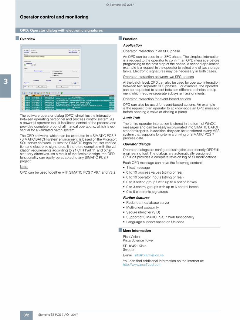
The software operator dialog (OPD) simplifies the interaction between operating personnel and process control system. Asa powerful operator tool, it facilitates control of the process and provides complete proof of all manual operations, which is es-sential for a validated batch system.
The OPD software, which can be executed in a SIMATIC PCS 7 / SIMATIC BATCH system environment, is based on the Microsoft SQL server software. It uses the SIMATIC logon for user verifica-tion and electronic signatures. It therefore complies with the val-idation requirements according to 21 CFR Part 11 and other statutory directives. As a result of the flexible design, the OPD functionality can easily be adapted to any SIMATIC PCS 7 project.
Note:
OPD can be used together with SIMATIC PCS 7 V8.1 and V8.2.
■ Function
Application
Operator interaction in an SFC phase
An OPD can be used in an SFC phase. The simplest interaction is a request to the operator to confirm an OPD message before progressing to the next step of the phase. A second application example is a request to the operator to select one of two storage tanks. Electronic signatures may be necessary in both cases.
Operator interaction between two SFC phases
At the batch level, OPD can also be used for operator interaction between two separate SFC phases. For example, the operator can be requested to select between different technical equip-ment which require separate subsystem assignments.
Operator interaction for event-based actions
OPD can also be used for event-based actions. An example is the request to an operator to acknowledge an OPD message before opening a valve or closing a pump.
Audit Trail
The entire operator interaction is stored in the form of WinCC messages and can be easily incorporated into SIMATIC BATCH standard reports. In addition, they can be transferred to any MES system that supports long-term archiving of SIMATIC PCS 7 process data.
Operator dialogs
Operator dialogs are configured using the user-friendly OPDEdit engineering tool. The dialogs are automatically versioned. OPDEdit provides a complete revision log of all modifications.
Each OPD message can have the following content:• 1 text message• 0 to 10 process values (string or real)• 0 to 10 operator inputs (string or real)• 0 to 3 option groups with up to 6 option boxes• 0 to 3 control groups with up to 6 control boxes• 0 to 5 electronic signatures
Further features• Redundant database server• Multi-client capability• Secure identifier (SID)• Support of SIMATIC PCS 7 Web functionality• Language support based on Unicode
■ More information
PlantVisionKista Science Tower
SE-16451 KistaSweden
E-mail: [email protected]
You can find additional information on the Internet at:http://www.pcs7opd.com
© Siemens AG 2017

3/3Siemens ST PCS 7 AO · 2017
3
Operator control and monitoring
Alarm Control Center: quick and reliable fault signaling
■ Overview
The ability to quickly and reliably signal fault conditions to the responsible persons is becoming increasingly important in modern control systems.
The modular alarm management system, Alarm Control Center (ACC), accomplishes this task by sending SIMATIC PCS 7 error messages fully automatically to a variety of possible recipients in a variety of ways:• Android smart phones with ACC-App via SMS, Internet and
WLAN• iPhones with ACC app via Internet• SMS on cell phones• Text messages to Ascom and Funktel pagers• Voice output on telephones via ISDN and VoIP• Text messages and voice output on HiPath/Hicom/
OpenScape telephones• E-mail to suitable receivers
Note:
The Alarm Control Center can be used together with SIMATIC PCS 7 V7.1, V8.0, V8.1 and V8.2.
■ Function
Important features• Integrated shift and personnel management for time-
dependent delivery of messages to different persons• Comprehensive escalation system for reliable delivery of
messages even if individual receivers cannot be reached• Operation and configuration throughout the network thanks to
Web capability• Integration of operation and configuration in SIMATIC PCS 7
process pictures for the control room personnel
■ Options
Options enable individual adaptation to an operator’s specific requirements – ranging from integration into a single SIMATIC PCS 7 station through to the implementation of company-wide fail-safe communication solution:• Redundancy for high availability systems• Alarm filter for suppressing message bursts, follow-on
messages, and chatter messages• System monitoring for monitoring alerting functions by means
of cyclic hardware and software component testing• Logging of changes to the configuration such as deletion of a
telephone number or reorganizing the call sequence• Dialog module option for integrating customer-specific
functions such as a quantity query• Teleconferencing for up to 30 participants• Forwarding of an emergency call to up to 10 participants• Personnel monitoring for safeguarding personnel who work
alone in hazardous areas
■ More information
Alarm IT Factory GmbHDornhaldenstr. 670199 StuttgartGermany
Tel.: +49 711 62 007 690Fax: +49 711 62 007 699
E-mail:
Sales: [email protected]
Delivery: [email protected]
Support: [email protected]
You can find additional information on the Internet at:http://www.alarmcontrolcenter.de
Alarm Control Center
SIMATIC PCS 7
© Siemens AG 2017

3/4 Siemens ST PCS 7 AO · 2017
3
Operator control and monitoring
Large-screen systems for control rooms
■ Overview
Apart from the type and scope of the presentation of information, the architecture of the control center is a major criterion influenc-ing the decision of the control system customer. The full specifi-cation of a control center includes recommendations relating to screen, image encoder technology, installation, lighting, air con-ditioning and software.
As a reliable partner for the user-friendly configuration of control centers with large-screen systems, Barco Control Rooms pays particular attention to the balance between functional, ergo-nomic and economic aspects.
Control rooms with large-screen systems based on back-projec-tion and LCD systems from Barco Control Rooms are ergonomic and functional. They provide an exceptional working atmo-sphere, and impressively represent the plant within the company and toward customers and visitors.
Note:
Large-screen systems from Barco Control Rooms can be used in combination with SIMATIC PCS 7 V7.1, V8.0, V8.1 and V8.2.
■ Function
The many years of experience of Barco Control Rooms in the de-velopment of back-projection and LCD systems is reflected in the comprehensive range of products based on state-of-the-art tech-nologies. The range includes the following standard products:
System Screen diagonal Technical specifications
OverView LED series (4:3)
OVL-508, 708, 808
OVL-515, 715, 815
50", 70", 80" Single-chip DLP with LED
Type x08 = resolution XGA (1024 × 768 pixels)Type x15 = resolution SXGA+ (1400 x 1050 pixels)
16.7 million colors, LED lighting, automatic brightness and color adjustment
Digital interface (DVI-D) and web-based service interface
OverView LED series (16:9)
OL-521, 721
OL-510, 710
OLF-510, 521, 710, 721
50", 70" Single-chip DLP with LED
Type x21 = Full HD resolution (1920 × 1080 pixels) Type x10 = HD Ready resolution (1360 × 768 pixels)
16.7 million colors, LED lighting, automatic brightness and color adjustment
Digital interface (DVI-D)and web-based service interface
OLF: Front access, small space requirements
MVL-721 70"
ODL-721; ODLF-721 70" Single-chip DLP with LASER
Full HD resolution (1920 × 1080 pixels),16.7 million colors, RGB LASER lighting, automatic brightness and color adjustment
Digital interface (DVI-D)and web-based service interface
ODLF: Front access, small space requirements
LCD video walls
IVD-5521, KVD-5521 55" LCD display, nearly seamless (3.5 mm), direct LED backlight
Full HD resolution (1920 × 1080 pixels), automatic brightness and color adjustment SenseX, 2 × DVI, 1 × DisplayPort in/out, external power supply (optional)
IVD: Brightness 700 cd/m2
KVD: Brightness 500 cd/m2
OpSpace
OpSpace – the high resolution pixel image
OpSpace is a workplace solution for operating personnel. It offers a single, adjustable and real-time view of required information via simple access to various applications, remote desktops and video streams. Signals from all sources – including from different networks – are amalgamated and dis-played in a ‘pixel image’, i.e. a single, coherent, high-resolution display area. Each individual signal can be freely moved, expanded or reduced within this display area. Via a single operating channel (mouse/keyboard/audio), the operator has seamless access to all sources.
© Siemens AG 2017

3/5Siemens ST PCS 7 AO · 2017
3
■ Function (continued)
Operator control and monitoring
Large-screen systems for control rooms
All large-screen systems have a modular structure. Several screens can be combined into a panel of any size. The panel is thus a large monitor on which graphic objects and information can be displayed and moved beyond the limits of the individual screens.
The image sources offer exceptional brightness and contrast values as well as sharp and distortion-free pictures. The auto-matic brightness and color adjustment of all modules of a LED big screen using Sense6 technology guarantees a uniform and ergonomic image quality.
All back-projection and LCD systems have standardized inter-faces for the display of computer applications, video and monitor signals. They can be connected directly to the SIMATIC PCS 7 operator stations without any additional configuration (plug & play).
The back-projection and LCD systems from Barco Control Rooms are optimized for low-maintenance 24/7 operation.For example, the O(V)L series can operate for 5 years without maintenance.
■ More information
Barco Control Rooms GmbHGreschbachstr. 5a76229 KarlsruheGermany
Germany (Central Europe)
Tel.: +49 721 6201630E-mail: [email protected]
Belgium (Western Europe)
Tel.: +32 5626 2063E-mail: [email protected]
USA (North America)
Tel.: +1 678 475 8158
Brazil (South America)
Tel.: +55 11 3513 1000E-mail: [email protected]
Dubai UAE (Middle East)
Tel.: +971 4 375 6803E-mail: [email protected]
Asia
Beijing
Tel.: +86 400 88 22726
Singapore
Tel.: +65 62437610
Japan
Tel.: +81 3 5762 8727
Additional information on the Internet
See:www.barco.com
© Siemens AG 2017

3/6 Siemens ST PCS 7 AO · 2017
3
Operator control and monitoring
KVM extender: Operator channel extensions
■ Overview
Using the Keyboard Video Mouse extenders from Guntermann & Drunck GmbH, you can extend the operating channel of the SIMATIC PCS 7 Industrial Workstation. It is then possible to spa-tially separate the display and operation components from the computer, and position operator stations up to 10 000 m away from the computer. KVM extenders provide signal transmission in real-time and without loss of performance occurs.
The KVM extenders transfer the following computer signals:• Video (single or multiple)• Keyboard, mouse (PS/2 and USB)• USB 2.0/USB 1.1 (optional)• Audio (optional)• RS 232 (optional)• Remote power (optional)
You can select the following product versions depending on re-quirements (further differences can be found under "Technical specifications"):
Note:
All KVM Extenders can be used together with SIMATIC PCS 7 V7.1, V8.0, V8.1 and V8.2.
■ Application
With the aid of the KVM extenders, the operating personnel can operate and monitor the process from the control room, while the computers are located in a secure and air-conditioned technol-ogy room separate from the operator panels. Thanks to the sep-arate installation of the computers, maintenance work by the IT administrators can be carried out centrally in the technology room. Another advantage: The work carried out by operators in the control room is not interfered with or interrupted by servicing.
Concentrated working is thus possible without fan noise or the dissipated heat of computers.
Product version Transmission of Max. distance
VGA DVI single link
DVI dual link
Display-Port
DVI Vision CAT/fiber
• 140 m (CAT) or 10 000 m (fiber)
CATVision • 300 m
LwLVision • • 10 000 m
DP Vision • • 140 m (CAT) or 10 000 m (fiber)
DL-Vision • 10 000 m
DL-Vision DP • • 10 000 m
© Siemens AG 2017

3/7Siemens ST PCS 7 AO · 2017
3
Operator control and monitoring
KVM extender: Operator channel extensions
■ Design
KVM Extender LWLVision, transmitter (top) and receiver (bottom)
The KVM extenders DVI-Vision-CAT/Fiber, CATVision, LwLVision, DL-Vision/DL-Vision-DP and DP-Vision each consist of a trans-mitter and receiver in desktop or 19" design which are con-nected to one another by means of a CAT cable (5/6/7) or a fiber-optic cable. They are independent of the system platform and the operating system. An operator station can be set up at both the transmitter and receiver (local console for maintenance di-rectly on the computer).
DL-Vision/DL-Vision-DP and DP-Vision have a redundant power supply. The other KVM extenders are also optionally available with a redundant power supply. If a power supply fails, the re-dundant supply unit immediately takes over. The connection to the computer is thus retained without interruption.
The standard interfaces are used for the computer connection. Neither software settings nor computer adjustments are neces-sary.
KVM extender DL-Vision-DP, receiver, rear view
DL-Vision/DL-Vision-DP and DP-Vision have two network connections, a Web interface, and a monitoring function. This enables both simple configuration as well as monitoring andreporting of monitoring values via the web interface.
The KVM Extender DL-Vision, DL-Vision-DP, DVI-Vision-CAT/Fiber and DP-Vision feature a screen freeze function. If a monitor loses the video signal or if there is a problem with the graphic controller of the remote computer, the screen freeze function freezes the last displayed image.
All KVM Extenders support multi-channel operation with 2 or up to 4 video signals. Depending on the multi-monitor graphic cards of the computer and the selected KVM extender, it is pos-sible to implement multi-monitor operator stations with up to 4 screens each.
By means of an KVM switch, local maintenance by an adminis-trator can be centralized in the control room.
© Siemens AG 2017

3/8 Siemens ST PCS 7 AO · 2017
3
Operator control and monitoring
KVM extender: Operator channel extensions
■ Technical specifications
Note:
Depending on the cable medium and video signal used, the systems feature automatic image optimization mechanisms.
■ More information
Guntermann & Drunck GmbHSystementwicklungDortmunder Str. 4a57234 WilnsdorfGermany
Tel.: +49 2739 8901-100Fax: +49 2739 8901-120
E-mail: [email protected]
You can find additional information on the Internet at:https://www.gdsys.de/
Specification DVI Vision CAT or fiber
CATVision LwLVision DP Vision DL Vision or DL Vision DP
Local operator station (console) Yes Yes Yes Yes Yes
Maximum transmissiondistance in m
CAT: 140
Fiber: 10 000 m via single-mode fibers, 400 m via multi-mode fibers
300 550/10 000 CAT: 140
Fiber: 10 000 m via single-mode fibers, 400 m via multi-mode fibers
10 000 m via single-mode fibers, 300 m via multi-mode fibers
Transmission medium Cable CAT5e and higher / fiber
CAT5, CAT6, CAT7 cable
Fiber: Multi-mode/single-mode fibers
Cable CAT5e and higher / fiber
Fiber: Multi-mode/single-mode fibers
Signals always possible for transmission
Keyboard, video, mouse, RS 232, audio
Keyboard, video, mouse Keyboard, video, mouse, RS 232, audio
Keyboard, video, mouse, RS 232, audio
Keyboard, video, mouse, audio, RS 232
Additional signals which can be transmitted (optional)
transp. USB 2.0 and USB HID Generic
RS 232, audio, USB 2.0 USB 2.0 USB 2.0 USB 2.0
Keyboard/mouse format
PS/2 and USB (also mixed mode)
PS/2 and USB (also mixed mode)
PS/2 and USB (also mixed mode)
PS/2 and USB (also mixed mode)
PS/2 and USB (also mixed mode)
Video• Input Digital (single link) Analog Analog or digital
(single link)Digital (single link) Digital
(dual link or DisplayPort)• Output Analog or digital Analog Analog or digital Analog or digital Digital• Maximum resolution (every
resolution within this band-width is supported)
1920 × 1200 at 60 Hz 1920 × 1440 at 75 Hz (depending on dis-tance)
1280 × 1024 at 75 Hz,1920 × 1200 at 60 Hz
1920 × 1200 at 60 Hz Per video channel: 2560 × 1600 at 60 Hz (2K × 2K)4096 × 2160 at 30 Hz (4K)
2 video channels:3840 × 2160 at 60 Hz (Ultra HD)4096 × 2160 at 60 Hz (4K)
• Number of channels Up to 4 Up to 4 Up to 2 Up to 4 Up to 4
Expandability With KVM switch With KVM switch With KVM switch With KVM switch With KVM switch
© Siemens AG 2017

3/9Siemens ST PCS 7 AO · 2017
3
Operator control and monitoring
KVM matrix switches: Flexible operator station administration
■ Overview
Using the KVM matrix systems, you can access n servers of a system from m different operator stations locally and/or remotely. Remote access can be accomplished in various ways, over:• CAT cable, 1:1 (distances up to 300 m)• Fiber-optic cable (distances up to 10 km), for maximum
performance and availability• LAN (Local Area Network) or WAN (Wide Area Network)
"over IP" for access from any location
The product range offered is classified as follows depending on the video signal:• Digital KVM matrix systems
- ControlCenter-Compact CCC 80 (up to 79/1 or 1/79 operator stations/servers), CCC 64 (up to 63/1 or 1/63), CCC 48 (up to 47/1 or 1/47), CCC 32 (up to 31/1 or 1/31) and CCC 16 (up to 15/1 or 1/15)
- ControlCenter-Digital, with 288, 160 or 80 dynamic ports (DP), can be configured as desired as operator station connection or server connection
• Analog KVM matrix systems- CATCenter NEO 4/32, 8/32 or 16/64 (operator stations/
servers)- CompactCenter X2: 2/16 (operator stations/servers)
You can find the technical specifications of these products under "Technical specifications".
The CATCenter NEO and CompactCenter X2 KVM matrix sys-tems communicate via CAT cables (types 5, 6, 7). When using the modular ControlCenter-Digital and the ControlCenter-Com-pact, communication between operator station and server can be performed via CAT cables or fiber-optic cables (uniform or mixed).
Digital KVM matrix systems
The ControlCenter-Compact (CCC) and ControlCenter-Digital (CCD) KVM matrix systems operate the following signals:• Video (DVI single link, DisplayPort, HDMI or VGA)• Keyboard and mouse (USB and PS/2)• Audio bidirectional• RS 232 and USB 2.0• CCD, also additional signals from third-party devices e.g. USB
3.0 or SDI
A functional system comprises at least the following elements:• 1 × central unit (ControlCenter-Compact) or central unit + I/O
cards (ControlCenter-Digital)• 1 × server module (e.g. DVI-CPU)• 1 × operator station unit (e.g. DVI-CON)• 1 × transmission cable (CAT or fiber-optic cable) per port
The operator stations for ControlCenter-Compact and Control-Center-Digital are connected via operator station units such as DVI-CON (user consoles). ControlCenter-Compact and Control-Center-Digital access the external server interfaces via server modules such as DVI-CPU (connection dongle). Both the ControlCenter-Digital as well as the ControlCenter-Compact can be cascaded or stacked. Large installations with up to 4 000 servers can be realized in this way.
Using digital matrix terminal devices as extenders
Simple extender lines can also be created with a direct connec-tion of the matrix terminal device (CON and CPU). The individual components in this scenario are mutually compatible in relation to the video signals (VGA, DVI, DP) . The remote systems that are initially installed 1:1 can be combined, if needed, with a cen-tral matrix switch to allow the lines to be switched amongst them-selves.
Analog KVM matrix systems
The analog KVM matrix systems CATCenter NEO and CompactCenter X2 operate the following signals:• VGA• Keyboard and mouse (USB and PS/2)• Audio, selectable (only CATCenter NEO)
A functional system comprises at least the following elements:• 1 × central unit (CATCenter NEO or CompactCenter X2)• 1 × server module (CATpro2)• 1 × operator station unit (UCON), exception:
CompactCenter X2• 2 × transmission cable (CAT cable)
The operator stations are connected to the CATCenter NEO via user console modules (UCON). With the CompactCenter X2, the operator station is integrated in the KVM matrix system. Both KVM matrix systems access the external server interfaces via the CATPro2 server modules (connection dongle).
Whereas the CompactCenter X2 is used exclusively in stand-alone mode, the CATCenter NEO products can be combined and expanded with up to 2048 servers and 128 operator sta-tions. Using the "bridge function", the CATCenter NEO also be in-tegrated as a subordinate cascade in the digital matrix systems.
Note:
All KVM matrix systems can be used together with SIMATIC PCS 7 V7.1, V8.0, V8.1 and V8.2.
© Siemens AG 2017

3/10 Siemens ST PCS 7 AO · 2017
3
Operator control and monitoring
KVM matrix switches: Flexible operator station administration
■ Design
Digital KVM matrix system ControlCenter-Compact
Digital KVM matrix system ControlCenter-Compact, 1: ControlCenter-Compact, 2: DVI-CON, 3: DVI-CPU
The digital KVM matrix system ControlCenter-Compact enables independent operation of n servers from m operator stations consisting of monitor, keyboard, and mouse.
Thanks to the dynamic port technology, each individual Control-Center-Compact port can be configured either as a server unit connection or an operator station unit connection.
ControlCenter-Compact is offered in five graded versions: CCC 16, CCC 32, CCC 48, CCC 64 and CCC 80. In stand-alone mode, applications with up to 16, 32, 48, 64 or 80 terminal de-vices (server modules or operator station units) can be config-ured. The number of terminals can be greatly extended by cas-cading the devices, enabling implementation of large installations with hundreds of servers.
Typical applications for the ControlCenter-Compact are large plants with many servers which have to be controlled from several distributed operator stations.
ControlCenter-Compact modules
Digital KVM matrix system ControlCenter-Digital
Digital KVM matrix system ControlCenter-Digital, 1: ControlCenter-Digital, 2: DVI-CON, 3: DVI-CPU
The modular and highly flexible KVM matrix systemControlCenter-Digital enables independent operation of n servers from m operator stations consisting of monitor, key-board, and mouse. It is particularly suitable for large plants with numerous servers.
Thanks to the dynamic port technology, all ports can be used ei-ther as a server unit connection or an operator station unit con-nection. The ControlCenter-Digital automatically detects whether a server unit or operator station unit is connected.
Depending on the configuration level, up to 80, 160 or 288 ports are available for operator stations or servers. The configuration with 288 ports therefore allows 1 to 287 servers to be operated and monitored from 287 to 1 simultaneous operator stations. Even larger installations are possible by cascading and/or stacking.
The modular design can be flexibly adapted and expanded de-pending on the project requirements, since the controller, switch and I/O cards, as well as power supplies and fan modules, can be replaced rapidly and simply thanks to hot plugging/swap-ping.
Highlights• High flexibility thanks to complete modularity of system
components• Triple redundant power supply• Hot swapping of individual components
ControlCenter-Digital with 288 ports
Desk 1
Desk 2
Central technical area
Administration desk
Desk 1 Desk 2 Desk 3
Central technical area
Administration desk
© Siemens AG 2017

3/11Siemens ST PCS 7 AO · 2017
3
■ Design (continued)
Operator control and monitoring
KVM matrix switches: Flexible operator station administration
Analog KVM matrix system CATCenter NEO
Architecture with KVM matrix system CATCenter NEO (schematicrepresentation)1: CATCenter NEO, 2: UCON, 3: UCON-IP-NEO (+ local workstation), 4: CATpro2, 5: IP client
The analog KVM matrix system CATCenter NEO operates the VGA, keyboard, mouse and audio signals. It is designed for larger plants in which the servers are accessed from multiple operator stations. The operator stations can also be distributed between different locations.
In addition to the central unit, a functional system also comprises the additional modules required for connecting the servers and operator stations:• Central unit: KVM matrix system CATCenter NEO, versions for
4/32, 8/32 or 16/64 (operator stations/servers)• Operator station unit: User console UCON• Server unit: Server connection dongle CATpro2
CATCenter NEO modules
The KVM matrix system CATCenter NEO can be configured per Web interface. A network connection is integrated in all CATCenter NEO model versions (SNMP, Syslog, monitoring functionality, configuration).
Analog KVM matrix system CompactCenter X2
Architecture with analog KVM matrix system CompactCenter X2 (schematic representation), 1: CompactCenter X2, 2: CAT connection(to CATpro2), 3: Local workstation, 4: IP workstation
The analog KVM matrix system CompactCenter X2 operates the VGA, keyboard and mouse signals. It can be used for efficient administration and simultaneous operation of up to 16 servers from 2 operator stations:• 1 × analog, directly on the CompactCenter• 1 × per LAN/WAN over IP
The central administration of individual (distributed) plant sec-tions is a possible application example of an operator station connected by LAN/WAN over IP.
In addition to the central unit, a functional system also includes a module for connecting the server:• Central unit: KVM matrix system CompactCenter X2 with
2 integrated operator station connections• Server unit: Server connection dongle CATpro2, versions
CompactCenter X2 modules
© Siemens AG 2017

3/12 Siemens ST PCS 7 AO · 2017
3
Operator control and monitoring
KVM matrix switches: Flexible operator station administration
■ Technical specifications
■ More information
Guntermann & Drunck GmbHSystementwicklungDortmunder Str. 4a57234 WilnsdorfGermany
Tel.: +49 2739 8901-100Fax: +49 2739 8901-120
E-mail: [email protected]
You can find additional information on the Internet at:https://www.gdsys.de
You can find detailed information about the ControlCenter-Compact and its components at:https://www.gdsys.de/produkte/digitale-kvm-matrixsysteme/zentralmodule/controlcenter-compact
You can find detailed information about the ControlCenter-Digital and its components at:https://www.gdsys.de/produkte/digitale-kvm-matrixsysteme/zentralmodule/controlcenter-digital
You can find detailed information about the CATCenter NEO and its components in the Internet at:https://www.gdsys.de/produkte/analoge-kvm-matrixsysteme/zentralmodule/catcenter-neo
You can find detailed information about the CompactCenter X2 and its components in the Internet at:https://www.gdsys.de/produkte/analoge-kvm-matrixsysteme/zentralmodule/compactcenter-x
Specification ControlCenter-Compact ControlCenter-Digital CATCenter NEO (4, 8, 16) CompactCenter X2
Number of consoles or operator stations
Min. 1 to max. 79 + splitting into multiple clusters
Min. 1 to max. 287 + splitting into multiple clusters
4/8/16 (via operator station units UCON) + splitting into multiple clusters
2 (1 × local, analog; 1 × per LAN/WAN, over IP)
Number of servers Min. 1 to max. 79 + cascading/stacking
Min. 1 to max. 287 + cascading/stacking
32/32/64 + cascading 16
Video• Port Standard DVI interface, Display-
Port, HDMI and VGAStandard DVI interface, Display-Port, HDMI and VGA
Standard VGA interface, DVI Standard VGA interface, DVI
• Max. resolution
- Analog – – 1920 × 1440 at 60 Hz 1920 × 1440 at 60 Hz- Digital (over IP) Up to 2560 × 1600 at 60 Hz
or 3840 × 2160 at 30 Hz (4K)Up to 2560 × 1600 at 60 Hzor 3840 × 2160 at 30 Hz (4K)
1920 × 1200 at 60 Hz in accordance with VESA CVT-RB
1600 × 1200 at 60 Hz in accordance with VESA DMT or 1920 × 1200 at 60 Hz in accordance with VESA CVT-RB
• Bandwidth Up to 300 MHz Up to 300 MHz Up to 250 MHz Up to 250 MHz• H/V sync 50 ... 180 kHz, 30 ... 130 Hz 50 ... 180 kHz, 30 ... 130 Hz 50 ... 180 kHz, 30 ... 130 Hz 50 ... 180 kHz, 30 ... 130 Hz• Color depth 24 bit digital 24 bit digital 32 bit analog, 8 bit digital 32 bit analog, 8 bit digital• Image optimization Automatic video setting Automatic video setting Automatic video setting,
individually adjustableAutomatic video setting, individually adjustable
Keyboard/mouse• Interfaces in direction:
ServerPS/2, USB PS/2, USB PS/2, USB, SUN-USB, VT100 PS/2, USB, SUN-USB, VT100
• Interfaces in direction: Operator station
PS/2, USB PS/2, USB PS/2, USB, SUN-USB PS/2, USB, SUN-USB
Audio Bidirectional transmission of audio signals
Bidirectional transmission of stereo audio signals
Transmission of audio signals –
• Bandwidth 22 kHz, sampling rate 96 kHz 22 kHz, sampling rate 96 kHz 20 kHz, sampling rate 44 kHz –• Resolution 24 bit digital 24 bit digital 24 bit –
Construction type Compact Modular Compact Compact
© Siemens AG 2017

3/13Siemens ST PCS 7 AO · 2017
3
Operator control and monitoring
VisorX/NG: Video technology for process monitoring
■ Overview
Video technology can make a highly versatile contribution to-ward rationalization of production processes. Remote from the process, you are able to view important process sequences, evaluate the actual product state, direct the flow of goods, check areas which are difficult or even impossible to access, and much more.
The use of video technology in process automation permits, for example:• Prevention of production faults and waste• Optimization of energy costs for combustion processes • Saving of personnel costs
It is extremely easy to integrate live video data from web oranalog cameras into the SIMATIC PCS 7 operator system using VisorX/NG video technology products from ASE GmbH. The VisorX/NG video server is configured with ASE software. Otherwise, no additional settings are necessary.
Note:
The VisorX/NG video technology can be used together with SIMATIC PCS 7 V7.1, V8.0, V8.1 and V8.2.
■ More information
ASE GmbHLusshardtstrasse 676646 BruchsalGermany
Tel.: +49 7251 93259-0Fax: +49 7251 93259-99
E-mail: [email protected]
Additional information is available on the Internet at:
http://www.ase-gmbh.eu
■ Function
Real-time for all channels
The VisorX/NG video server works in real time, i.e. it is able to re-cord up to 25 images per second for each video channel. Image recording can be carried out time-based, event-controlled or also permanently.
Special features:• Digital saving and transmission of video and audio signals
together with multi-standard compression and state-of-the-art image analysis algorithms
• Video management functionality based on user-programmable, internal logic control
• Redundant power supply expansion and internal SATA RAID expansion possible
Event control
The live video images are displayed on the SIMATIC PCS 7 operator station as a continuous image and/or dependent on a request or controlled by a particular event.
IP cameras
The VisorX/NG software can be used to directly integrate video signals from web cameras into the SIMATIC PCS 7 process con-trol system. It can be integrated with Windows ActiveX.
Analog cameras
The image information recorded by up to 32 analog cameras is digitized in the VisorX/NG video server, saved in compressed form, and transferred to the SIMATIC PCS 7 process control sys-tem via an Ethernet interface.
Infrared cameras
Infrared cameras for recording of thermal images are particu-larly suitable for monitoring, evaluating and optimizing combus-tion processes, for determining temperature distributions, or for fire protection.
Camera control
Cameras with PTZ (pan/tilt/zoom) function or dome cameras can be controlled from any authorized workstation in the network using a mouse and keyboard.
Cascade option
As many as 32 cameras can be connected to each VisorX/NG video server. The number of cameras used can be extended as desired by cascading video servers.
History memory
The history memory enables precise analysis of a particular event by analyzing it in the long-term archive. Unauthorized access to the long-term archive can be checked by using a password (data protection). Every time archive material is accessed it is documented.
Licensing
Enabling of OS clients is based on the user's own license admin-istration which can be operated centrally or decentrally.
Routing through various subnets
VisorX/NG software is used to connect cameras and clients in different subnets.
Extreme ambient conditions
When combined with a wide range of enclosures, cameras can be used in hazardous areas (certified according to ATEX), in off-shore applications, or in furnaces.
Two-wire or fiber-optic cable
Dome camera
Alarm
Video server
Any analog cameras IP cameras
Switch
Switch
WorkstationSIMATIC PCS 7 operator system
Ethernet
Video LAN
PCS 7 LAN
© Siemens AG 2017

3/14 Siemens ST PCS 7 AO · 2017
3
Operator control and monitoring
SIMATIC HMI Thin Client Ex
■ Overview
SIMATIC HMI Thin Client Ex with international approvals for operation and monitoring in hazardous areas.
■ Application
The SIMATIC HMI Thin Client Ex is designed for use as an oper-ator station for terminal and client applications in hazardous ar-eas, and in particular for applications for which the performance of the SIMATIC HMI Panel PC Ex is insufficient, or when the server is located in a protected area of the plant. The widely-used RDP and Real VNC protocols are supported.
Together with the digital KVM Box, the device functions as a flex-ible monitor with touch functionality for PCs e.g. in control rooms.
■ Integration
Integrated interfaces with SIMATIC HMI Thin Client Ex:• 10/100 Mbit 100 base TX (Ex e) or 100 base FX (Ex op is)
network• 1 x RS232 or 1 x RS422/485• 4 x USB 2.0 (2 x Ex I, 2 x Ex e (version Zone 1) or 2 x Ex nA
(version Zone 2))
■ Technical specifications
SIMATIC HMI Thin Client Ex
General features
Design Thin Client built-in unit, available in protec-tive enclosure as an option
Front 15", 19", and 15" sunlight readable display
Operation Touch with 8 function keys
MTBF backlight 50 000 h
Operating system Closed system on Windows XP Embedded basis
Mass storage Integrated
Power supply 24 V DC, max. 2.1 A (19")
Interfaces
Ethernet 100 Mbit Ex e, or alternatively fiber-optics 100 Mbit (SC) Ex op is
USB 2.0 2 x Ex i, 2 x Ex e (Zone 1) or 2 x Ex nA (Zone 2)
Serial 1 x RS232 or 1 x RS422/485
Ambient conditions
Degree of protection IP66 at front, IP65 at rear, IP66 in protective enclosure
Ambient temperature during operation
- 20 °C ... + 50 °C, cold start -10 °C, with optional additional heating down to -30 °C
Relative humidity during operation
90 % at 40 °C, no condensation
Approvals/directives
Devices in "Zone 1" version
ATEX directive 94/9/EC• Network 10/100 Base-Tx II 2 (2) G Ex d e ia ib mb [ia ib] IIC T4 Gb
II 2 (2) D Ex ia tb [ia ib] IIIC T80°C Db IP66 • Network 10/100 Base-Fx II 2 (2) G Ex d e ia ib mb [ia ib op is] IIC
T4 GbII 2 (2) D Ex ia tb [ia ib op is] IIIC T80°C Db IP66
IECEx• Network 10/100 Base-Tx Ex d e ia ib mb [ia ib] IIC T4 Gb
Ex ia tb [ia ib] IIIC T80°C Db IP66• Network 10/100 Base-Fx Ex d e ia ib mb [ia ib op is] IIC T4 Gb
Ex ia tb [ia ib op is] IIIC T80°C Db IP66
GOST-R• Network 10/100 Base-Tx 2 Ex d e ia ib mb [iaib] IIC T4
DIP A21 TA80°C, IP66• Network 10/100 Base-Fx 2 Ex d e ia ib mb [iaibopis] IIC T4
DIP A21 TA80°C, IP66
CSA Ex d e ia ib mb [ia ib] IIC T4 Gb, Type 4X, IP66Class II, Division 1, Groups E, F, G, T80°CEx ia tb [ia ib] IIIC T80°C Db, IP66
KGS Ex d e ia ib mb [ia ib] IIC T4Ex ia tb [ia ib] IIIC T80°C Db IP66
InMetro• Network 10/100 Base-Tx Ex d e ia ib mb [ia ib] IIC T4 Gb
Ex ia tb [ia ib] IIIC T80°C Db IP66• Network 10/100 Base-Fx Ex d e ia ib mb [ia ib op is] IIC T4 Gb
Ex ia tb [ia ib op is] IIIC T80°C Db IP66
SIMATIC HMI Thin Client Ex
© Siemens AG 2017

3/15Siemens ST PCS 7 AO · 2017
3
■ Technical specifications (continued)
Operator control and monitoring
SIMATIC HMI Thin Client Ex
Devices in version "Zone 2"
ATEX directive 94/9/EC• Network 10/100 Base-Tx II 3 (2/3) G Ex d e ia ib mb nA [ib Gb] [ic]
IIC T4 GcII3 (2/3) D Ex ia tc [ib Db] [ic] IIIC T80°C Dc IP66
• Network 10/100 Base-Fx II 3 (2/3) G Ex d e ia ib mb nA [ib op is Gb] [ic] IIC T4 GcII 3 (2/3) D Ex ia tc [ib op is Db] [ic] IIIC T80°C Dc IP66
IECEx• Network 10/100 Base-Tx Ex d e ia ib mb nA [ib Gb] [ic] IIC T4 Gc
Ex ia tc [ib Db] [ic] IIIC T80°C Dc IP66• Network 10/100 Base-Fx Ex d e ia ib mb nA [ib op is Gb] [ic] IIC
T4 GcEx ia tc [ib op is Db] [ic] IIIC T80°C Dc IP66
GOST-R• Network 10/100 Base-Tx 2 Ex de i a ib mb nA [ib][ic] IIC T4
DIP A21 TA80°C, IP66• Network 10/100 Base-Fx 2 Ex de i a ib mb nA [ibopis][ic] IIC T4
DIP A21 TA80°C, IP66
CSA Ex d e ia ib mb nA [ib Gb] [ic] IIC T4 Gc, Type 4X, IP66Class II, Division 2, Groups E, F, G, T80°C; Ex ia tc [ib ic] IIICT80°C Dc, IP66
InMetro• Network 10/100 Base-Tx Ex d e ia ib mb nA [ib Gb] [ic] IIC T4 Gc
Ex ia tc [ib Db] [ic] IIIC T80°C Dc IP66• Network 10/100 Base-Fx Ex d e ia ib mb nA [ib op is Gb] IIC T4
Ex ia tc [ib op is Db] [ic] IIIC T80°C Dc IP66
Protocols RDP, RealVNC
Digital KVM switch Input: DVI / VGA, PS/2 / USB, output: RJ45 (IP network)
Dimensions
Mounting dimensions (W x H x D) in mm
15": 427.5 x 327.5 x 165 19": 522.5 x 412.5 x 165
Front dimensions in mm 15": 440 x 340 19": 535 x 425
Weight 15": 15 kg, 19": 23 kg
SIMATIC HMI Thin Client Ex
■ Ordering data Article No.
Note:
Please assemble the required IPC configuration using the TIA Selection Tool or configurator in the Industry Mall in order to ensure suitability; we do not accept any liability for configura-tions compiled by users themselves.
SIMATIC HMI Thin Client Ex 6AV7200-
0 0 0 - A 0
Design / display size• Zone 2: 15" touch with function
keysA
• Zone 2: 19" touch with function keys
B
• Zone 1: 15" touch with function keys
D
• Zone 1: 19" touch with function keys
E
• Zone 2: 15" touch, sunlight readable with function keys
G
• Zone 1: 15" touch, sunlight readable with function keys
H
Communication interfaces• 10/100 base Tx, Ex e A
• 100 base Fx FOC (SC), Ex op is B
Enclosure options (device is delivered already fitted)• without 0
• Stainless steel enclosure for:
- Wall mounting 2
- Stand (incl. coupling, 300° rotation possible)
3
- Suspension bracket (incl. coupling, 300° rotation possible)
4
- Support arm (incl. coupling, 300° rotation possible)
5
- Swivel arm from above (incl. coupling, 300° rotation possible)
6
External keyboard for enclosure (incl. keyboard enclosure)• without A
• QWERTZ keyboard B
• QWERTY keyboard C
• AZERTY keyboard D
• QWERTZ keyboard with trackball E
• QWERTY keyboard with trackball F
• AZERTY keyboard with trackball G
Further options together with stainless steel enclosure• Breather glands
• Heating (requires breather glands)
• Handles
• Front USB (at bottom)
Accessories
Digital KVM forHMI Thin Client Ex
6AV7675-0EX00-0AA0
USB drive• Intrinsically safe, 8 GB 6AV7675-0FX00-0AA0• Intrinsically safe, 8 GB with
recovery function6AV7675-0FX10-0AA0
Ethernet switch 6AV7675-0PX00-0AA0
With FOC 4 x 100 Base Tx, 1 x 100 Base (MTRJ) Fx Ex op is
© Siemens AG 2017

3/16 Siemens ST PCS 7 AO · 2017
3
Operator control and monitoring
SIMATIC HMI Thin Client Ex
■ Dimensional drawings
Legend:h = Mounting clamp (10 x)i = Clamping framej = Control cabinet or enclosure
All dimensions in mm. For mounting cut-out see technical specifications.
SIMATIC HMI Thin Client Ex 15"
SIMATIC HMI Thin Client Ex 19"
■ More informationAdditional information is available on the Internet at:www.siemens.com/simatic-hmi-ex
327.
5+0.
5
427.5+0.5 G_S
T80_
XX
_004
19
165
326
340
440
426
jih
15" touch front Width in mm Height in mm Depth in mm
Operating unit 440 340 165
Installation cutout 427.5 ± 0.5 327.5 ± 0.5 -
412.
5+0.
5
522.5+0.5 G_S
T80_
XX
_004
20
165
411
425
535
521
jih
19" touch front Width in mm Height in mm Depth in mm
Operating unit 535 425 165
Installation cutout 522 ± 0.5 412.5 ± 0.5 -
© Siemens AG 2017

3/17Siemens ST PCS 7 AO · 2017
3
Operator control and monitoring
Mouse-Trak: Trackball
■ Overview
As an alternative to the standard mouse, the "Mouse-Trak"trackball mouse is offered for operating SIMATIC PCS 7 operator stations. The Mouse-Trak is available in two versions for different applications. The devices are equipped either with a PS/2 or USB interface.
Note:
Mouse-Trak Professional and Mouse-Trak Industrial are compat-ible to SIMATIC PCS 7 V7.1, V8.0, V8.1 and V8.2.
■ Design
• Mouse-Trak Professional for problem-free continuous use in office environments- B5XXMP-XROHS (PS/2)- B5XUSB-XROHS (USB)
• Mouse-Trak Industrial for harsh environmental requirements (see figure)- BMPIND-XROHS (PS/2)- BUSBID-XROHS (USB)
■ More information
Chameleon Group GmbHViersener Straße 172D-47877 WillichGermany
Tel.: +49 2156 3065476Fax: +49 2156 4989157
E-mail: [email protected]
Additional information is available on the Internet at:
www.chameleon-group.com
© Siemens AG 2017

3/18 Siemens ST PCS 7 AO · 2017
3
Operator control and monitoring
Notes
© Siemens AG 2017

Siemens ST PCS 7 AO · 2017
44/2 SIMOCODE pro block library
4/5 AS-Interface block library
Libraries/blocks/tools
© Siemens AG 2017

4/2 Siemens ST PCS 7 AO · 2017
4
Libraries/blocks/tools
SIMOCODE pro block library
■ Overview
Faceplates for motor control and measured value display in APL design
The SIMOCODE pro block library for SIMATIC PCS 7 enables the SIMOCODE pro motor management system to be easily and conveniently integrated in the SIMATIC PCS 7 process control system. The number of configuration steps is thus reduced sig-nificantly.
Depending on the design of the library, signal processing and technological functions of the blocks are matched to the PCS 7 Standard Library (driver blocks, technological blocks) or the PCS 7 Advanced Process Library (APL) and are optimally tai-lored to the functions of the motor management system.
Users who previously configured motor feeder circuits using conventional technology by means of signal blocks and motor or valve blocks can now easily switch to the SIMOCODE pro library for SIMATIC PCS 7.
Using the library blocks, SIMOCODE pro can also be integrated into the asset management of the SIMATIC PCS 7 Maintenance Station. This does not involve any extra configuration effort.
The library comprises:• Blocks for the automation system (AS)
- Driver blocks- SIMOCODE-specific blocks- Measured-value and statistics block- Time stamp block / log block
• Elements (symbols and faceplates) for operation and monitoring using an operator station (OS)
Note:
The various versions of the block library SIMOCODE pro for SIMATIC PCS 7 can be used in SIMATIC PCS 7 V7.1, V8.0, V8.1 and V8.2 as follows:• SIMOCODE pro V8 in SIMATIC PCS 7 V8.0, V8.1 and V8.2 with
PCS 7 Advanced Process Library (APL)• SIMOCODE pro V7 in SIMATIC PCS 7 V7.0 and V7.1 with
PCS 7 Standard Library• SIMOCODE pro Migration V7-V8 for upgrading the
SIMOCODE pro V7 block library for use in SIMATIC PCS 7 V8.0, V8.1 and V8.2, based on the PCS 7 Standard Library
For details on licenses for these designs, see "License information" in the "Function" section.
■ Application
The SIMOCODE pro motor management system has been de-signed for use in Motor Control Centers (MCC) in the process in-dustry and power plant engineering. It is especially predestined for the automation of processes in which plant standstill results in very high costs.
Potential plant downtimes can be efficiently prevented using the detailed operating, service and diagnostics data of SIMOCODE pro. In the event of a fault, you are able to determine and eliminate the cause extremely quickly.
■ Function
The blocks of the SIMOCODE pro library for SIMATIC PCS 7 are suitable for SIMOCODE pro devices on the PROFIBUS DP which are operated either directly following a PROFIBUS DP master system (standard automation systems) or following a Y-link (fault-tolerant automation systems).
The SIMOCODE pro block library for SIMATIC PCS 7 V8, which is based on the Advanced Process Library (APL), also supports the integration of SIMOCODE pro V PN via PROFINET IO (on a SIMATIC PCS 7 AS Single Station as well as one-sided, system-redundant I/O on a SIMATIC PCS 7 AS Redundancy Station).
© Siemens AG 2017

4/3Siemens ST PCS 7 AO · 2017
4
■ Function (continued)
Libraries/blocks/tools
SIMOCODE pro block library
Display of statistical data in APL design
The optional measured value and statistics block makes avail-able numerous measured values and statistics information of the SIMOCODE pro motor management system in addition to the comprehensive diagnostics information.
The time stamp block permits the use of the time stamping func-tion of the SIMOCODE pro V connected to PROFIBUS DP forSIMATIC PCS 7. It transfers the signals already provided with a time stamp in the device to the automation system, and enters them into the operator station's message list.
The library blocks support all SIMOCODE pro control functions:• Overload (OVL)• Direct starter, soft starter (DIR, SOFT)• Reversing starter, soft starter with reversing starter (REV,
SOFT)• Star-delta (STAR)• Star-delta with direction reversal (REVS)• Dahlander, pole-changing switch (DAHL, POL)• Dahlander, pole changing switch with direction reversal
(DAHL REV, POL REV)• Valve, positioner (VALVE, POS)• Circuit breaker (CB)
License information
The engineering software of the SIMOCODE pro block libraryfor SIMATIC PCS 7 is supplied with two licenses, both of which correspond to the single license type:• Engineering license for configuration on one engineering
station• Runtime license for execution of AS blocks in one automation
system
A runtime license is also required for each additional automation system in which the AS blocks are executed. In contrast to the engineering software, the CD with the software and documenta-tion is not included in the scope of delivery of separately ordered runtime licenses.
The Engineering Software Migration V7-V8 enables upgrade of a SIMOCODE pro block library for SIMATIC PCS 7 with Engineering Software V7 (tailored to the PCS 7 Standard Library) for use with SIMATIC PCS 7 V8.0, V8.1 and V8.2. An installation requirement for the Engineering Software Migration V7-V8 is the engineering license for the Engineering Software V7. This en-ables the Engineering Software Migration V7-V8 to be installed directly under SIMATIC PCS 7 V8.x . It is not necessary to install the Engineering Software V7 beforehand.
© Siemens AG 2017

4/4 Siemens ST PCS 7 AO · 2017
4
Libraries/blocks/tools
SIMOCODE pro block library
■ Ordering data Article No. Article No.
■ More information
Siemens AGDigital FactoryControl ProductsP.O. Box 235590713 FürthGermany
Technical specificationshttps://support.industry.siemens.com/cs/de/de/ps/16718/td
Programming and operating manualsBlock libraries "SIMOCODE pro PCS 7 Library":Version 8.2: https://support.industry.siemens.com/cs/ww/de/view/103954289Version 8.0+SP3: https://support.industry.siemens.com/cs/ww/de/view/84626047
Online support
http://www.siemens.de/industrial-controls/support
Technical questionsSubmit your technical questions to:Technical AssistanceTel.: +49 911 895-5900E-mail: [email protected]
You can find additional information in the Internet at:www.siemens.de/simocode
Block library SIMOCODE pro for SIMATIC PCS 7 V8 with PCS 7 Advanced Process Library (APL)
Engineering softwareAS blocks, symbols, and faceplates for integrating SIMOCODE pro into SIMATIC PCS 7, tailored to the PCS 7 Advanced Process Library; with• Engineering license for one
engineering station• Runtime license for one
automation system
Engineering and runtime software, software class A, 2 languages (German, English), single license for 1 installation
Delivery package: Certificates of license; software and electronic documentation on CD• V8 for SIMATIC PCS 7 V8.0, V8.1
and V8.23ZS1632-1XX02-0YA0
• Upgrade from V6/V7 to V8 3ZS1632-1XX02-0YE0
Runtime license V8For execution AS blocks for SIMOCODE pro in an automation system; required for using the AS blocks of the Engineering Software V8 in a plant
Runtime software, software class A, language-neutral, single license for 1 installation
Delivery package: Certificate of License
3ZS1632-2XX02-0YB0
Block library SIMOCODE pro for SIMATIC PCS 7 V7 without PCS 7 Advanced Process Library (APL)
Engineering softwareAS blocks, symbols, and faceplates for integrating SIMOCODE pro into SIMATIC PCS 7, tailored to the PCS 7 Standard Library; with• Engineering license for one
engineering station• Runtime license for one
automation system
Engineering and runtime software, software class A, 3 languages (English, German, French), single license for 1 installation
Delivery package: Certificates of license; software and electronic documentation on CD• V7 for SIMATIC PCS 7 V7.0 and
V7.13UF7982-0AA10-0
• Upgrade from V6 to V7 3UF7982-0AA13-0
Engineering Software Migration V7-V8For upgrading (migrating) a SIMOCODE pro block library with Engineering Software V7 for use with SIMATIC PCS 7 V8
AS blocks, symbols, and faceplates for integrating SIMOCODE pro into SIMATIC PCS 7 V8.x, tailored to the PCS 7 Standard Library; with license for upgrading an engineer-ing license and all associated run-time licenses of the SIMOCODE pro block library in a SIMATIC PCS 7 system
Engineering and runtime software, software class A, 3 languages (English, German, French), single license for 1 installation
Delivery package: Certificates of license; software and electronic documentation on CD
Note: An installation requirement is the engineering license for the Engineering Software V7 of the SIMOCODE pro block library for SIMATIC PCS 7. EngineeringSoftware Migration V7-V8 can be installed directly under SIMATIC PCS 7 V8x. Previous installation of the Engineering Software V7 is not necessary.
3UF7982-0AA20-0
Runtime license V7For execution of AS blocks for SIMOCODE pro in an automation system; required for using the AS blocks of the Engineering Software V7 or the Engineering Software Migration V7-V8 in a plant
Runtime software, software class A, language-neutral, single license for 1 installation
Delivery package: Certificate of License
3UF7982-0AA11-0
© Siemens AG 2017

4/5Siemens ST PCS 7 AO · 2017
4
Libraries/blocks/tools
AS-Interface block library
■ Overview
AS-Interface block library for SIMATIC PCS 7 in the CFC
The AS-Interface (AS-i) is an open, cross-vendor bus system for networking simple actuators and sensors (usually binary) in the bottom field area, and allows simultaneous transmission of data and power over one unshielded 2-wire cable.
The AS-Interface can be integrated very simply into the SIMATIC PCS 7 process control system using the AS-Interface block li-brary for SIMATIC PCS 7. Fundamental advantages of the AS-i can then be used:• Easy installation• Low wiring costs when using simple actuators and sensors
with SIMATIC PCS 7
The block library reduces the engineering requirements for interfacing the AS-i to SIMATIC PCS 7 to the positioning and interconnecting of AS-i blocks in the CFC. AS-i diagnostics using the SIMATIC PCS 7 Maintenance Station does not require any additional configuration.
Note:
The AS-Interface block library can be used in systems with SIMATIC PCS 7 V7.1, V8.0, V8.1 and V8.2 (for details on the corresponding block library and SIMATIC PCS 7 software, see Design, License information).
■ Design
The AS-Interface block library for SIMATIC PCS 7 contains:• Blocks for access to the I/O data of AS-i slaves• Blocks for diagnostics of the AS-i system• Faceplates for the SIMATIC PCS 7 Maintenance Station
License information
The following software versions of the AS-Interface block library are available for SIMATIC PCS 7:• Engineering Software V8.1 for SIMATIC PCS 7 V8.0 as of SP1
Update 3, V8.1 or V8.2 (each based on the Advanced Process Library); recommended for new SIMATIC PCS 7 projects
• Engineering Software Migration V7-V8 for SIMATIC PCS 7 V8.0 as of SP1, V8.1 or V8.2 (each without Advanced Process Library); recommended for upgrading SIMATIC PCS 7 V7 projects to V8 with small amount of adaptation in the project
• Engineering Software V7 for SIMATIC PCS 7 V7.1 (without Advanced Process Library)
The Engineering Software of the block library AS-Interface for SIMATIC PCS 7 is delivered with 2 licenses, both of which corre-spond to the single license type:• Engineering license for configuration on one engineering
station• Runtime license for execution of AS blocks in one automation
system
One runtime license is also additionally required for each further automation system in which the AS blocks are executed. In con-trast to the Engineering Software, the CD with the software and documentation is not included in the scope of delivery of sepa-rately ordered runtime licenses.
An extra license is not required to use the faceplates on the SIMATIC PCS 7 maintenance station.
The Engineering Software Migration V7-V8 enables you to upgrade an AS-Interface block library for SIMATIC PCS 7 with Engineering Software V7 for use with SIMATIC PCS 7 V8.0 as of SP1, V8.1 or V8.2. An installation requirement for the Enginee-ring Software Migration V7-V8 is the engineering license for the Engineering Software V7 of the AS-Interface block library for SIMATIC PCS 7 V7.0 or V7.1. Engineering Software Migration V7-V8 can be installed directly under SIMATIC PCS 7 V8.0, V8.1 or V8.2. It is not necessary to previously install the Engineering Software V7 of the AS-Interface block library for SIMATIC PCS 7.
Service Packs
The Engineering Software product package always includes the corresponding service pack of the block library where available.
The service packs for Engineering Software Migration V7-V8or for Engineering Software V7 are only available in the package together with Engineering Software. They are not available for download.
© Siemens AG 2017

4/6 Siemens ST PCS 7 AO · 2017
4
Libraries/blocks/tools
AS-Interface block library
■ Function
The AS-Interface can be integrated into the process control system as follows using the AS-Interface block library forSIMATIC PCS 7:• Direct connection on the PROFIBUS DP via DP/AS-i LINK
Advanced (AS-i single or double master)• Connection via a CP 343-2 or CP 343-2P AS-i master module
in an ET 200M remote I/O station on the PROFIBUS DP or PROFINET IO
• Direct connection on the PROFINET IO via IE/AS-i LINK PN IO (AS-i single or double master)
• Connection via a CM AS-i Master ST AS-i master module in an ET 200SP remote I/O station to the IM 155-6PN (High Feature) interface module on the PROFINET IO
AS-i integration in SIMATIC PCS 7 via PROFIBUS DP
AS-i integration in SIMATIC PCS 7 via PROFINET IO
The AS interface operates according to the master/slave princi-ple. The AS-i master module (DP/AS-i LINK Advanced, CP 343-2, CP 343-2P, CM AS-i Master ST or IE/AS-i LINK PN IO) controls the slaves (sensors/actuators) connected via AS-i cable.
Supported AS-i devices
AS-i master
The AS-i block library for SIMATIC PCS 7 supports the following AS-i masters:• CP 343-2 in ET 200M station, article number
6GK7343-2AH01-0XA0• CP 343-2P in ET 200M station, article number
6GK7343-2AH11-0XA0• DP/AS-i LINK Advanced Single Master, article number
6GK1415-2BA10• DP/AS-i LINK Advanced Double Master, article number
6GK1415-2BA20• IE/AS-i LINK PN IO Single Master, article number
6GK1411-2AB101) (with Engineering Software V8 or V8.1)• IE/AS-i LINK PN IO Double Master, article number
6GK1411-2AB201) (with Engineering Software V8 or V8.1)• CM AS-i Master ST in ET 200SP station, article number
3RK7137-6SA00-0BC11) (only with Engineering Software V8.1)
1) Only AS-Interface block library for SIMATIC PCS 7 V8 with Advanced Process Library (APL)
AS-i slaves
Digital AS-i slaves with standard addressing and extended ad-dressing (A/B slaves) are generally suited for deployment on the CM AS-i Master ST, CP 343-2 or CP 343-2P. The CP 343-2 and CP 343-2P AS-i masters transfer I/O data from AS-i slaves with a B address via data records but not via the cyclic process image (partition). To prevent delays in the communication process of the driver blocks for B slaves, we recommend avoiding the use of AS-i slaves with B addresses for SIMATIC PCS 7 configura-tions with CP 343-2 or CP 343-2P.
Digital as well as analog AS-i slaves with standard addressing and extended addressing (A/B slaves) can be operated on the DP/AS-i LINK Advanced or on the IE/AS-i LINK PN IO.
Diagnostics
Diagnostics are carried out using faceplates in the SIMATIC PCS 7 Maintenance Station. Faults in the AS-i devices are additionally signaled in plain text.
SIMATIC PCS 7 automation systems
AS-islaveStandard
AS-islaveA
AS-islaveStandard
AS-islaveA/B
AS-Interface AS-Interface
IM 1
53-2
CP
343
-2
PROFIBUS
G_P
CS
7_X
X_0
0228
DP/AS-i LINKAdvanced
AS-islaveA/B
AS-islaveStandard
AS-islaveA/B
AS-islaveStandard
SIMATIC PCS 7 automation systems
SIMATIC ET 200SP with CM AS-i Master ST
G_P
CS
7_X
X_0
0385
IE/AS-i LINK PN IO
PROFINET
AS-Interface AS-Interface
© Siemens AG 2017

4/7Siemens ST PCS 7 AO · 2017
4
Libraries/blocks/tools
AS-Interface block library
■ Ordering data Article No. Article No.
■ More information
Note:
Engineering Software V8.1 is available for download from the In-ternet as an upgrade package. Engineering Software V8+SP1 is required for installation of the upgrade package. In addition to the upgrade package, a hotfix for the Engineering Software V8+SP1 (without upgrade) is available for download, see https://support.industry.siemens.com/cs/de/en/view/109480456
Programming manuals• AS-Interface block library for SIMATIC PCS 7 V8 with Advanced
Process Library see:https://support.industry.siemens.com/cs/ww/en/view/90690873
• AS-Interface block library for SIMATIC PCS 7 V8 without Advanced Process Library (Migration V7-V8) see:https://support.industry.siemens.com/cs/ww/en/view/105795722
• AS-Interface block library for SIMATIC PCS 7 V7 without Advanced Process Library see:https://support.industry.siemens.com/cs/ww/en/view/46504691
For additional information on the use of analog AS-i slaves in a configuration with SIMATIC PCS 7 V8.1, see:• https://support.industry.siemens.com/cs/ww/en/view/109474836• https://support.industry.siemens.com/cs/ww/en/view/109474832
SupportTechnical Assistance
Tel.: +49 911 895 5900Fax: +49 911 895 5907E-mail: [email protected] Support on the Internet
www.siemens.com/sirius/supportSupport Request on the Internet
http://support.industry.siemens.com/My/ww/en/requests
AS-Interface block library for SIMATIC PCS 7 V8 with Advanced Process Library (APL)
Engineering Software V8.1AS blocks and faceplates for inte-grating AS-Interface into SIMATIC PCS 7 V8.2, V8.1 or V8.0 as of SP1 (with Advanced Process Library); with:• Engineering license for
1 engineering station• Runtime license for 1 automation
system
Engineering and runtime software, software class A, 2 languages (German, English), single license for 1 installation
Delivery package: Certificates of license; software and electronic documentation on CD
3ZS1635-1XX02-0YA0
Runtime license V8For execution of AS blocks for AS-Interface in an automation sys-tem; suitable for AS blocks of the Engineering Software V8 or V8.1
Runtime software, software class A, 2 languages (English, German), single license for 1 installation
Delivery package: Certificate of License
3ZS1635-2XX02-0YB0
AS-Interface block library for SIMATIC PCS 7 V8 without Advanced Process Library (APL)
Engineering Software Migration V7-V8For upgrading (migrating) an AS-Interface block library with Enginee-ring Software V7 for use with SIMATIC PCS 7 V8.0 as of SP1, V8.1 or V8.2 (without Advanced Process Library)
AS blocks and faceplates for inte-grating AS-Interface into SIMATIC PCS 7 V8.0 as of SP1; V8.1 or V8.2 (including SP2 of the block library) with license for upgrading an engi-neering license and all associated runtime licenses of the AS-Interface block library in a SIMATIC PCS 7 system
Engineering and runtime software, software class A, 2 languages (English, German), single license for 1 installation
Delivery package: Certificates of license; software and electronic documentation on CD
Note:The engineering license for Engineering Software V7 of the AS-Interface block library for SIMATIC PCS 7 V7.0/V7.1 is required for installation. Enginee-ring Software Migration V7-V8 can be installed directly under SIMATIC PCS 7 V8. Previous installation of the Engineering Software V7 is not necessary.
3ZS1635-1XX11-0YE0
AS-Interface block library for SIMATIC PCS 7 V7 without Process Library (APL)
Engineering Software V7AS blocks and faceplates for inte-grating AS-Interface into SIMATIC PCS 7 V7.1 (without Advanced Process Library); with:• Engineering license for
1 engineering station• Runtime license for 1 automation
system(including SP1 of the block library)
Engineering and runtime software, software class A, 2 languages (German, English), single license for 1 installation
Delivery package: Certificates of license; software and electronic documentation on CD
3ZS1635-1XX01-0YA0
Runtime license V7For execution of AS blocks for AS-Interface in an automation sys-tem; suitable for AS blocks of Engineering Software V7 or Engineering Software Migration V7-V8
Runtime software, software class A, 2 languages (English, German), single license for 1 installation
Delivery package: Certificate of License
3ZS1635-2XX01-0YB0
© Siemens AG 2017

4/8 Siemens ST PCS 7 AO · 2017
4
Libraries/blocks/tools
Notes
© Siemens AG 2017

Siemens ST PCS 7 AO · 2017
55/2 Function blocks for SIWAREX
weighting modules
5/6 Drive ES PCS 7: Function blocks for drives
5/10 AddFEM: Redundant I/O modules for fastresponse times
5/14 AirLINE Ex: Pneumatic block for integration intoET 200iSP
5/16 SIMATIC RF: RFID systems
Distributed I/O on PROFIBUS
© Siemens AG 2017

5/2 Siemens ST PCS 7 AO · 2017
5
Distributed I/O on PROFIBUS
Function blocks for SIWAREX weighing modules
■ Overview
Level, proportioning, belt, and loss-in-weight scales in process engineering applications can be quickly and efficiently configured using pre-configured weighing blocks. The uniform design of the SIWAREX weighing controllers matching that of SIMATIC ET 200M or ET 200SP also enables easy and consistent wiring in the control cabinet.
For the SIMATIC PCS 7 process control system, Siemens offers configuration packages with function blocks for the SIWAREX U, SIWAREX FTA, SIWAREX FTC and SIWAREX WP321 weighing controllers. These weighing blocks are suitable for both stan-dard and fault-tolerant automation systems. In high-availability automation systems, the singularly installed SIWAREX U/FTA/FTC/WP321 can be accessed via both subsystems.
The weighing blocks supplied with the faceplate not only allow the rational integration of the SIWAREX U/FTA/FTC/WP321 weighing controllers into the engineering system, they also en-able user-friendly operation and commissioning of the scales via the SIMATIC PCS 7 operator stations. Integrated signaling be-havior and maintenance functions such as the reading or writing of all scale parameters ensure short standstill times and help to increase the availability.
The pixel-graphics engineering with the CFC editor is very clear and easy to use. The use of prepared blocks also eliminates possible sources of errors and reduces the configuration costs.
Note:
The function blocks and faceplates for weighing controllers can be used together with SIMATIC PCS 7 V7.1, V8.0, V8.1 and V8.2 (depending on the version of the configuration package, with one or more of these versions, in the style of PCS 7 StandardLibrary or the PCS 7 Advanced Process Library). For details on this, see the following product overview.
G_P
CS
7_X
X_0
0374
© Siemens AG 2017

5/3Siemens ST PCS 7 AO · 2017
5
Distributed I/O on PROFIBUS
Function blocks for SIWAREX weighing modules
■ Design
Product overview SIWAREX configuration packages for SIMATIC PCS 7 and the associated weighing controller
Configuration packages, variants Associated hardware (SIWAREX weighing controller)
Article number
SIWAREX U (platform weighing machine/level measurement)
• For SIMATIC PCS 7 V8.0 (as of Update 1), V8.1 and V8.2, PCS 7 Advanced Process Library design
• For SIMATIC PCS 7 V8.0, V8.1 and V8.2, PCS 7 Standard Library design
• For SIMATIC PCS 7 V7.1, PCS 7 Standard Library design
SIWAREX U (1-channel), in design of ET 200M 7MH4950-1AA01
SIWAREX U (2-channel), in design of ET 200M 7MH4950-2AA01
SIWAREX FTA (automatic dosing and filling scales)• For SIMATIC PCS 7 V8.0 (as of
Update 1), V8.1 and V8.2, PCS 7 Advanced Process Library design
• For SIMATIC PCS 7 V8.0, V8.1 and V8.2, PCS 7 Standard Library design
• For SIMATIC PCS 7 V7.1, PCS 7 Standard Library design
SIWAREX FTA, in design of ET 200M 7MH4900-2AA01
SIWAREX FTC_B (conveyor scales)• For SIMATIC PCS 7 V8.0 (as of
Update 1), V8.1 and V8.2, PCS 7 Advanced Process Library design
• For SIMATIC PCS 7 V8.0, V8.1 and V8.2, PCS 7 Standard Library design
• For SIMATIC PCS 7 V7.1, PCS 7 Standard Library design
SIWAREX FTC, with ET 200M design 7MH4900-3AA01
SIWAREX FTC_L (differential proportioning weigher)• For SIMATIC PCS 7 V8.0, V8.1 and
V8.2, PCS 7 Standard Library design• For SIMATIC PCS 7 V7.1, PCS 7
Standard Library design
SIWAREX FTC, with ET 200M design 7MH4900-3AA01
SIWAREX WP321 (platform weighing machine/level measurement)• For SIMATIC PCS 7 V8.1 and V8.2,
PCS 7 Advanced Process Library design
SIWAREX WP321, in design of ET 200SP 7MH4138-6AA00-0BA0
© Siemens AG 2017

5/4 Siemens ST PCS 7 AO · 2017
5
Distributed I/O on PROFIBUS
Function blocks for SIWAREX weighing modules
■ Ordering data Article No. Article No.
1) For further accessories (earthing terminals, etc.), refer to the corre-sponding device manual!
SIWAREX U
SIWAREX U configuration package (platform weighing machine/level measurement)consisting of function block, face-plate, parameterization software and manual, 2 languages (German, English), engineering license for SIWAREX U, single license for 1 installation
Engineering and runtime software, software class A
Delivery package: Software and electronic documentation on CD, engineering license (certificate of license)• For SIMATIC PCS 7 V8.0 (as of
Update 1), V8.1 and V8.2(in design of PCS 7 Advanced Process Library)
7MH4950-3AK65
• For SIMATIC PCS 7 V8.0, V8.1 and V8.2 (in design of PCS 7 Standard Library)
7MH4950-3AK62
• For SIMATIC PCS 7 V7.1(in the design of the PCS 7 Standard Library)
7MH4950-3AK61
Associated hardware (SIWAREX U weighing controller):• SIWAREX U (1-channel)1) 7MH4950-1AA01• SIWAREX U (2-channel)1) 7MH4950-2AA01
SIWAREX FTA
SIWAREX FTA configuration package (automatic dosing and filling scales)consisting of function block, face-plate, parameterization software and manual, 2 languages (German, English), engineering license for SIWAREX FTA, single license for 1 installation
Engineering and runtime software, software class A
Delivery package: Software and electronic documentation on CD, engineering license (certificate of license)• For SIMATIC PCS 7 V8.0 (as of
Update 1), V8.1 and V8.2(in design of PCS 7 Advanced Process Library)
7MH4900-2AK65
• For SIMATIC PCS 7 V8.0, V8.1 and V8.2 (in design of PCS 7 Stan-dard Library)
7MH4900-2AK63
• For SIMATIC PCS 7 V7.1(in the design of the PCS 7 Standard Library)
7MH4900-2AK62
Associated hardware (SIWAREX FTA weighing controller):
SIWAREX FTA1) 7MH4900-2AA01
SIWAREX FTC_B
SIWAREX FTC_B configuration package (belt scales)consisting of function block, face-plate, parameterization software and manual, 2 languages (German, English), engineering license for SIWAREX FTC, single license for 1 installation
Engineering and runtime software, software class A
Delivery package: Software and electronic documentation on CD, engineering license (certificate of license)• For SIMATIC PCS 7 V8.0 (as of
Update 1), V8.1 and V8.2(in design of PCS 7 Advanced Process Library)
7MH4900-3AK67
• For SIMATIC PCS 7 V8.0, V8.1and V8.2 (with design of PCS 7 Standard Library)
7MH4900-3AK65
• for SIMATIC PCS 7 V7.1(in the design of the PCS 7 Standard Library)
7MH4900-3AK63
Associated hardware (SIWAREX FTC weighing controller):
SIWAREX FTC1) 7MH4900-3AA01
SIWAREX FTC_L
SIWAREX FTC_L configuration package (loss-in-weight scales)consisting of function block, face-plate, parameterization software and manual, 2 languages (German, English), engineering license for SIWAREX FTC, single license for 1 installation
Engineering and runtime software, software class A
Delivery package: Software and electronic documentation on CD, engineering license (certificate of license)• For SIMATIC PCS 7 V8.0, V8.1
and V8.2 (with design of PCS 7 Standard Library)
7MH4900-3AK66
• for SIMATIC PCS 7 V7.1(in the design of the PCS 7 Standard Library)
7MH4900-3AK64
Associated hardware (SIWAREX FTC weighing controller):
SIWAREX FTC1) 7MH4900-3AA01
SIWAREX WP321
SIWAREX WP321 configuration package (platform weighing machine/level measurement)consisting of function block, face-plate, configuration software and manual, 2 languages (German, English), engineering license for SIWAREX WP321, single license for 1 installation
Engineering and runtime software, software class A
Delivery package: Software and electronic documentation on CD, engineering license (certificate of license)• For SIMATIC PCS 7 V8.1 and V8.2
(in design of PCS 7 Advanced Process Library)
7MH4138-1AK61
Associated hardware (SIWAREX WP321 weighing controller)
SIWAREX WP3211) 7MH4138-6AA00-0BA0
© Siemens AG 2017

5/5Siemens ST PCS 7 AO · 2017
5
Distributed I/O on PROFIBUS
Function blocks for SIWAREX weighing modules
■ More information
Siemens AGProcess Industries and DrivesProcess AutomationProcess Instrumentation, Weighing Technology
Tel.: +49 721 595-2811Fax: +49 721 595-2901
E-mail: [email protected]
You can find additional information on the Internet at:http://www.siemens.com/weighing-technology
© Siemens AG 2017

5/6 Siemens ST PCS 7 AO · 2017
5
Distributed I/O on PROFIBUS
Drive ES PCS 7: Function blocks for drives
■ Overview
Faceplates in classic style (left) and APL style (right)
Drive ES PCS 7 enables Siemens drives to be controlled via SIMATIC PCS 7 and operated and monitored in the operator station. The Drive ES PCS 7 faceplates make the data relevant to plant operation available on the operator station.
Drive ES PCS 7 also provides the drive data relevant to the PCS 7 Asset Management for display on the maintenance station.
The Drive ES Basic configuration software1) or the STARTER1) commissioning software (as of V4.3 SP2) can be used on the en-gineering station for configuration, commissioning and detailed diagnostics of the drive.
Note:
Drive ES PCS 7 is offered in the following versions:• Drive ES PCS 7 APL with blocks in the design of the PCS 7
Advanced Process Library (APL Style) in versions for SIMATIC PCS 7 V8.0, V8.1 or V8.2
• Drive ES PCS 7 with blocks in the design of the PCS 7 Standard Library (Classic Style) in versions for SIMATIC PCS 7 V8.0, V8.1 or V8.2
1) Instead of Drive ES Basic, only the STARTER commissioning software can be used for MICROMASTER (4th generation) and SINAMICS drives. STARTER (as of V4.3 SP2) provides Drive ES Basic functionality for these drive types.
■ Application
Drive ES PCS 7 can integrate the following drive series into SIMATIC PCS 7:• SIMOVERT MASTERDRIVES VC and MC2)
• MICROMASTER 3.2) and 4. Generation• SIMOREG DC Master2)
• SINAMICS S110/S120/S150• SINAMICS G120• SINAMICS G130/G150• SINAMICS MV (product designations GM150, GL150, SL150,
SM120)• SINAMICS DC MASTER (SINAMICS DCM)• SINAMICS DCP (bidirectional DC/DC actuator)2) Only the library in the classic style is available for these drives.
As of Drive ES PCS 7 APL V8.0+SP1 or Drive ES PCS 7 V8.0+SP1 (classic), SINAMICS drives can be integrated on PROFINET in SIMATIC PCS 7 in addition to drives on PROFIBUS DP.
You can find a detailed list of the drives supported with Drive ES PCS 7 V8.2 on the Internet for:• Drive ES PCS 7 APL V8.2
https://support.industry.siemens.com/cs/ww/en/view/109739002• Drive ES PCS 7 V8.2 (Classic Style)
https://support.industry.siemens.com/cs/ww/en/view/109738265
You can find detailed information on the drives supported by Drive ES PCS 7 predecessor versions in the respective product notifications in the Product Support section of Industry Online Support on the Internet:https://support.industry.siemens.com
MICROMASTER
MICROMASTER inverters are standard frequency inverters in the power range from 0.12 to 250 kW and can be used in numer-ous variable-speed drive applications. They are especially suit-able for applications with pumps, fans and in conveyor systems. Their large range of line voltages enables them to be used all over the world.
SINAMICS
SINAMICS is the latest family of drives from Siemens for innova-tive and future-proof drive solutions in a wide performance range from 0.12 to 4 500 kW with line voltages from 380 to 690 V. Char-acteristic of the devices from the SINAMICS family, which are based on a shared platform concept, is their integrated function-ality, high degree of flexibility, and facility for combination.
SINAMICS S
The SINAMICS S120 drive system is a modular system for high-performance applications in industrial machine construction and plant engineering. A wide range of matched designs, com-ponents and functions always enables you to find an optimum solution. SINAMICS S120 can be used to implement powerful single drives and coordinated drives (multi-axis applications) with vector or servo functionality.
SINAMICS S150 are designed as cabinet units for variable-speed drives in machine construction and plant engineering. They are particularly suitable for variable-speed drives with high requirements placed on dynamic response and speed accu-racy, frequent braking cycles with high braking energies, and four-quadrant operation.
© Siemens AG 2017

5/7Siemens ST PCS 7 AO · 2017
5
■ Application (continued)
Distributed I/O on PROFIBUS
Drive ES PCS 7: Function blocks for drives
SINAMICS G
SINAMICS G single drives (AC/AC converters) are specialists for all applications where solid, liquid or gaseous materials have to be moved, transported, pumped or compressed through the use of conveyor belts, pumps, fans and compressors.
The product range of universally deployable SINAMICS G120 single drives includes:• Compact G120C single drives for the low performance range
(0.55 to 18.5 kW)• Modular G120 single drives for the low to medium perfor-
mance range (0.37 to 250 kW)
SINAMICS G130 built-in units and SINAMICS G150 cabinet units for powers from 75 to 2 700 kW round off the top performance range.
SINAMICS MV
SINAMICS MV is an integrated range of medium-voltage converters which is unique worldwide and covers all levels of dynamics and performance in voltage classes from 2.3 to 11 kV. These SINAMICS MV drives cover a performance range from 0.8 kW to 85 MW at motor speeds of 10 to 15 000 rpm-1. They can be used for single drives as well as for multi-motor drives.
SINAMICS DC MASTER
SINAMICS DC MASTER (SINAMICS DCM) is the name for the latest generation of DC converters from Siemens. The SINAMICS DCM DC power converters combine the advantages of the previous generation, SIMOREG DC MASTER, with those of the SINAMICS series and serve the performance range from 6 kW to 3 MW.
SINAMICS DCM can be optimally integrated in any plants with the following device versions:• SINAMICS DCM DC Converters, the universal built-in unit• SINAMICS DCM Control Module for the modernization of
existing plants, particularly for extremely high performances• SINAMICS DCM Cabinet, the ready-to-connect and ready-
to-run drive cabinet for all DC drive technology applications
SINAMICS DCP (bidirectional DC/DC actuator)
The name SINAMICS DC Power Converter (SINAMICS DCP) represents a new generation of bi-directional DC/DC actuators from Siemens, which combines extensive expertise of DC tech-nology with the advantages of the SINAMICS product series.
Typical applications and areas of application:• Braking chopper• Coupling of DC busses with different levels of voltage• Battery check status• Mining conveyor belts• BESS (Battery Energy Storage Systems)• Wind energy and photovoltaics
© Siemens AG 2017

5/8 Siemens ST PCS 7 AO · 2017
5
Distributed I/O on PROFIBUS
Drive ES PCS 7: Function blocks for drives
■ Ordering data Article No. Article No.
Drive ES PCS 7 in the design of the PCS 7 Advanced Process Library (APL Style)
Drive ES PCS 7 APLFunction blocks and faceplates in the style of the PCS 7 Advanced Process Library (APL) for integra-tion of variable-speed drives in SIMATIC PCS 7, for example, SINAMICS, SINAMICS DCM, SINAMICS DCP, SINAMICS MV, SINAMICS S/G and MICROMASTER 4xx
with electronic documentation(5 languages); single license for one engineering station each, consisting of:• Engineering license for one
engineering station• Runtime license for one
automation system
Engineering and runtime software, software class A, 5 languages (English, German, French, Italian, Spanish), single license for 1 installation
Delivery package: Certificates of license; software and electronic documentation on CD• V8.2 for SIMATIC PCS 7 V8.2
Runs on Windows 7 SP1 Enterpri-se/Ultimate/Professional 64-bit or Windows Server 2008 R2 SP1 Standard 64-bit;only for OS section of the library on the OS client: Windows 7 SP1 Enterprise/Ultimate 32-bit, Windows 10 Enterprise 2015 LTSB 64-bit, Windows Server 2012 R2 SP1 Standard 64-bit
6SW1700-8JD01-2AA0
• V8.1 incl. SP1) for SIMATIC PCS 7 V8.1Runs on Windows 7 SP1 Enterpri-se/Ultimate 32/64-bit, Windows Server 2008 R2 SP1 Standard 64-bit
6SW1700-8JD01-1AA0
• V8.0 incl. SP1) for SIMATIC PCS 7 V8.0Runs on Windows XP Professional 32-bit, Windows Server 2003/2003 R2 Standard 32-bit, Windows 7 Enterprise/Ultimate 32/64-bit, Windows Server 2008 Standard 32-bit or 2008 R2 Standard 64-bit
6SW1700-8JD01-0AA0
Drive ES PCS 7 in the design of the PCS 7 Standard Library (Classic Style)
Drive ES PCS 7 (classic style)Function blocks and faceplates in the style of the PCS 7 Standard Library for integration of variable-speed drives in SIMATIC PCS 7, for example, SIMOVERT MASTER-DRIVES, MICROMASTER 4xx, SIMOREG DC MASTER, SINAMICS DCM, SINAMICS DCP; SINAMICS MV and SINAMICS S/G
with electronic documentation(5 languages); single license for one engineering station each, consisting of:• Engineering license for one
engineering station• Runtime license for one
automation system
Engineering and runtime software, software class A, 5 languages (English, German, French, Italian, Spanish), single license for 1 installation
Delivery package: Certificates of license; software and electronic documentation on CD• V8.2 for SIMATIC PCS 7 V8.2
Runs on Windows 7 SP1 Enterpri-se/Ultimate/Professional 64-bit or Windows Server 2008 R2 SP1 Standard 64-bit;only for OS section of the library on the OS client: Windows 7 SP1 Enterprise/Ultimate 32-bit, Windows 10 Enterprise 2015 LTSB 64-bit, Windows Server 2012 R2 SP1 Standard 64-bit
6SW1700-8JD00-2AA0
• V8.1 incl. SP1) forSIMATIC PCS 7 V8.1Runs on Windows 7 SP1 Enterpri-se/Ultimate 32/64-bit, Windows Server 2008 R2 SP1 Standard 64-bit
6SW1700-8JD00-1AA0
• V8.0 incl. SP1) for SIMATIC PCS 7 V8.0Runs on Windows XP Professional 32-bit, Windows Server 2003/2003 R2 Standard 32-bit, Windows 7 Enterprise/Ultimate 32/64-bit, Windows Server 2008 Standard 32-bit or 2008 R2 Standard 64-bit
6SW1700-8JD00-0AA0
AS runtime licenseDrive ES PCS 7
AS runtime license Drive ES PCS 7 for SIMATIC PCS 7 V8.0, V8.1 and V8.2For processing of function blocks in an automation system
language-neutral, single license for 1 installation
Delivery package: Certificate of License
6SW1700-5JD00-1AC0
© Siemens AG 2017

5/9Siemens ST PCS 7 AO · 2017
5
■ Ordering data Article No. Article No.
Distributed I/O on PROFIBUS
Drive ES PCS 7: Function blocks for drives
1) The most recent Update/Service Pack (SP) is always supplied.2) When upgrading from Drive ES PCS 7 (Classic Style) to Drive ES PCS 7
APL, the SIMATIC PCS 7 user software must be reconfigured.3) You can find information on the supported operating systems in the
product notifications for the respective versions of Drive ES PCS 7, Drive ES PCS 7 APL or Drive ES Basic in Product Support of the Industry Online Support on the Internet, seehttps://support.industry.siemens.com
■ More information
Siemens AGDigital FactoryMotion ControlGeneral Motion ControlProduct Management Drives
Erlangen
Tel.: +49 9131 98-47215Fax: +49 9131 98-6538
You can also find the latest product information, FAQs and manuals at Product Support for Industry Online Support in the Internet (https://support.industry.siemens.com) under "Drive technology – Selection and engineering tools – DRIVE ES configuration software or STARTER commissioning software"
You can find additional information in the Internet at:http://www.siemens.com/drive-es
Drive ES Basic configuration software
Drive ES BasicSoftware package for easy parame-terization, commissioning and diag-nostics of Siemens drives using a central engineering station, includ-ing routing beyond network bound-aries; with electronic documentation (5 languages)
Engineering software, software class A, 5 languages (English, German, French, Italian, Spanish)
Delivery package: Certificate of license; software and electronic documentation on DVD• V5.5 including SP1)3)
for SIMATIC PCS 7 V8.0, V8.1 and V8.2, single license (floating license for 1 user)
6SW1700-5JA00-5AA0
• V5.5 including SP1)3)
for SIMATIC PCS 7 V8.0, V8.1 and V8.2, floating license for 60 concurrent users
6SW1700-5JA00-5AA1
Upgrades and software update service
Drive ES PCS 7 APL upgrade2)
For single license
Engineering and runtime software, software class A
5 languages (English, German, French, Italian, Spanish), single license for 1 installation
Delivery package: Software and electronic documentation on CD• V8.0/V8.1 to V8.21)3)
and when upgrading from Drive ES PCS 7 (Classic Style) to Drive ES PCS 7 APL version2)
6SW1700-8JD01-2AA4
• V8.0/V8.0 including SP to V8.11)3)
and when upgrading from Drive ES PCS 7 (Classic Style) to Drive ES PCS 7 APL version2)
6SW1700-8JD01-1AA4
• V8.0 to V8.0 SP11)3)
and when upgrading from Drive ES PCS 7 (Classic Style) to Drive ES PCS 7 APL version2)
6SW1700-8JD01-0AA4
Drive ES PCS 7 Upgrade (Classic Style)For single license
Engineering and runtime software, software class A, 5 languages (English, German, French, Italian, Spanish), single license for 1 installation
Delivery package: Software and electronic documentation on CD• V6.x/V7.x/V8.0/8.1 to V8.21)3) 6SW1700-8JD00-2AA4• V6.x/V7.x/V8.0 to V8.11)3) 6SW1700-8JD00-1AA4• V6.x/V7.x to V8.01)3) 6SW1700-8JD00-0AA4
Drive ES Basic Upgrade V5.x to V5.5+SP1)3)
Engineering software, software class A, 5 languages (English,German, French, Italian, Spanish)
Delivery package: Software and electronic documentation on DVD
6SW1700-5JA00-5AA4
Software update serviceContract for the delivery of all updates/upgrades for 1 year; if not canceled, the contract is automati-cally extended for one more year
Delivery package: Written contract• Drive ES PCS 7 APL, single li-
cense (for 1 installation)for Drive ES PCS 7 in the designof the PCS 7 Advanced Process Library (APL)
6SW1700-0JD01-0AB2
• Drive ES PCS 7 (Classic Style), single license (for 1 installation)
6SW1700-0JD00-0AB2
© Siemens AG 2017

5/10 Siemens ST PCS 7 AO · 2017
5
Distributed I/O on PROFIBUS
AddFEM: Redundant I/O module for fast response times
■ Overview
The Front End Module AddFEM is an autonomous unit for the in-put/output of analog and digital process signals that can be con-nected with standardized protocols via the PROFIBUS DP field-bus to the SIMATIC PCS 7 automation system. Its fast response times for signal acquisition and processing should be particu-larly emphasized.
The product range consists of two versions:• AddFEM
- 12 analog inputs- 8 analog outputs- 12 digital inputs- 16 digital outputs (can also be configured as digital inputs)- 3 counter/timer inputs (can also be configured as digital
inputs)• AddFEM SoE (Sequence of Event) with a preprocessing Front
End Function (FEF)- 31 digital inputs with highly exact time tagging.
Both product versions can be operated in redundant pairs. The advantage of AddFEM redundancy is that the switchover in this case takes place independent of the automation system (CPU).
Note:
The AddFEM can be used in combination with SIMATIC PCS 7 V7.1, V8.0 from Update 1 upwards, V8.1 as well as V8.2.
■ Benefits
• Modules for operation independently or redundant in pairs• Fast response times for signal acquisition and processing as
well as for redundancy switchover (switchover time less than 500 s) of the AddFEM
• Extended level ranges for analog signals and counters of the AddFEM
• Analog and digital areas electrically isolated from one another• Permanently short-circuit-proof analog and digital inputs• Monitoring of all outputs• Outputs can be connected in parallel with other outputs
(redundancy, increase in performance)
■ Design
Built into a rugged high-grade steel housing, which is in line with the SIMATIC S7 design in terms of dimensions and shape, the AddFEM meets stringent environmental requirements. It is pre-pared for mounting on DIN rails and for direct mounting with bolts. These installation options support both freestanding con-struction and installation in cabinets or wall-mounted housings.
The connecting elements are protected by a removable hood on which the connector pin assignment of the I/O signals is printed. The functions are set by means of two mode selectors and indi-cated by 12 LEDs. In accordance with the PLC standard, 2 x 16 LEDs are available in the display panel of the module for signal-ing the binary I/O signals.
■ Function
AddFEM
The various signal types with AddFEM are distributed across the process connections in such a way that a single module is often sufficient for small applications. Applications with a large quan-tity framework can be implemented by using several modules.
The measuring ranges of the analog inputs and outputs are de-signed so that no additional signal transducers have to be used. By means of an additional current range of ± 50 mA for the ana-log outputs, actuators with higher power requirements, e.g. fuel control valves, can also be controlled without additional signal amplifiers.
AddFEM SoE (Sequence of Event) with a preprocessing Front End Function (FEF)
The Front End Module AddFEM SoE is tailored to the special applications in power plant and process control technology where exact time tagging is required when recording changes in signals, e.g. for archiving the statuses of a power plant for analysis of incidents or for general logging.
The AddFEM is synchronized by the GPS time server, and tags the binary signals with an accuracy of 1 ms.
The integrated redundancy in 3 levels and the fast, stand-alone switching over guarantee high availability. The module commu-nicates with the automation system over the redundant PROFIBUS DP.
The AddFEM SoE requires the AddFEM SoE repeater module for on-site signal distribution, adaptation of the medium (glass FOC to plastic FOC) and signal inversion.
© Siemens AG 2017
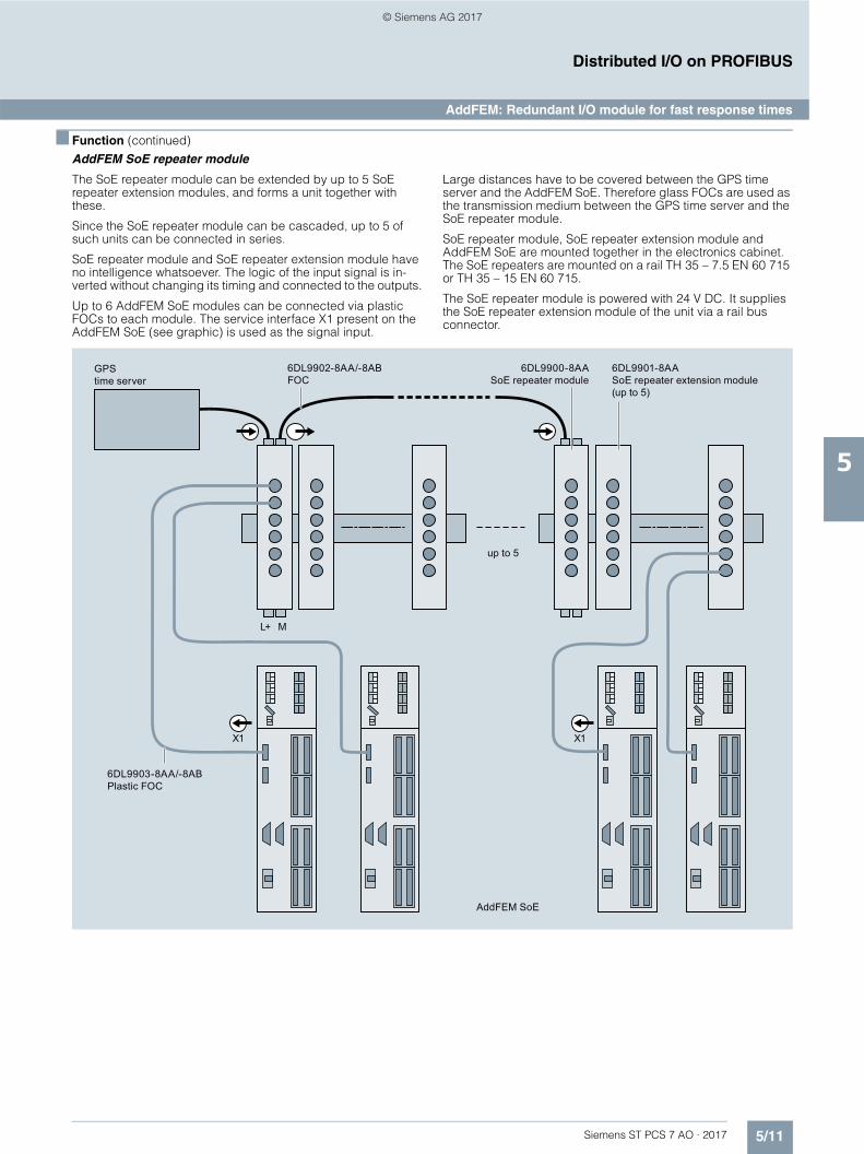
5/11Siemens ST PCS 7 AO · 2017
5
■ Function (continued)
Distributed I/O on PROFIBUS
AddFEM: Redundant I/O module for fast response times
AddFEM SoE repeater module
The SoE repeater module can be extended by up to 5 SoErepeater extension modules, and forms a unit together with these.
Since the SoE repeater module can be cascaded, up to 5 of such units can be connected in series.
SoE repeater module and SoE repeater extension module have no intelligence whatsoever. The logic of the input signal is in-verted without changing its timing and connected to the outputs.
Up to 6 AddFEM SoE modules can be connected via plastic FOCs to each module. The service interface X1 present on the AddFEM SoE (see graphic) is used as the signal input.
Large distances have to be covered between the GPS time server and the AddFEM SoE. Therefore glass FOCs are used as the transmission medium between the GPS time server and the SoE repeater module.
SoE repeater module, SoE repeater extension module and AddFEM SoE are mounted together in the electronics cabinet. The SoE repeaters are mounted on a rail TH 35 – 7.5 EN 60 715 or TH 35 – 15 EN 60 715.
The SoE repeater module is powered with 24 V DC. It supplies the SoE repeater extension module of the unit via a rail bus connector.
GPS time server
6DL9902-8AA/-8ABFOC
6DL9900-8AASoE repeater module
AddFEM SoE
up to 5
6DL9901-8AASoE repeater extension module (up to 5)
6DL9903-8AA/-8ABPlastic FOC
L+ M
X1 X1
© Siemens AG 2017

5/12 Siemens ST PCS 7 AO · 2017
5
Distributed I/O on PROFIBUS
AddFEM: Redundant I/O module for fast response times
■ Technical specifications
AddFEM/AddFEM SoE
General data
Dimensions (W × H × D) in mm 295 × 75 × 209
Weight 2.8 kg
Supply voltage 24 V DC
Bridging of power failures 10 ms (minimum)
Power consumption 20 W
PROFIBUS DP interfaces
Number of interfaces 2
Baud rate 12 Mbit/s
Max. cable length of a segment 100 m
Connectable load per interface 5 V, max. 80 mA
Digital inputs
Quantity 12
Type of input Type 1 compliant with IEC 1131-2
Voltage range -30 … +33 V DC
0 signal level -30 … +5 V DC
1 signal level +11 … +30 V DC
Galvanic isolation 3 groups with 4 digital inputs each
Display LED in display panel
Digital outputs
Quantity 16
Type of output Digital semiconductor outputs
Nominal output voltage 24 V DC
Output voltage with 0 signal < 1 V
Output voltage with 1 signal Power supply less 2 V
Rated output current 500 mA
Short-circuit proof Yes
Short-circuit-to-ground monitoring Yes (internal monitoring)
Galvanic isolation Yes (8 outputs each with samereference potential)
Analog inputs (parameterizable)
Inputs, total 12
Current input (fixed) 6
Current/voltage input 6
Measurement range of currentsinputs (parameterizable)
0 … 20 mA
4 … 20 mA
-20 … +20 mA
-30 … +30 mA
Measuring range of voltage input (parameterizable)
0 … 10 V-10 … +10 V
Input impedance, current 41.8
Input impedance, voltage 100 k
Max. error (over the entire temperature range)
0.2% relative to full-scale value
Resolution of A/D converter 13 bit + sign
Conversion method Successive approximation
Analog outputs (parameterizable)
Outputs, total 8
Current output range 0 … 20 mA (480 )
4 … 20 mA (480 )
± 20 mA (480 )
± 30 mA (300 )
± 50 mA (150 )
Max. error(over the entire temperature range)
0.4%
Resolution of A/D converter 13 bit + sign
Counting pulse input (parameterizable)
Number of inputs 3
Type of input Type 1/2 compliant with IEC 1131-2
Voltage range ±33 V DC
0 signal level -28 … +3 V
1 signal level +8 … +28 V
Load 1 … 3 k
Input frequency (fin) 0 … 20 kHz
Counter resolution 1/60 000 referred to measured value
Updating interval 2 ms
Digital inputs with time tagging: AddFEM SoE
Quantity 31
Time resolution 1 ms
Approvals/markings
UL Recognition Mark Underwriters Laboratories (UL)compliant with Standard UL 508 File E 85972
CSA Certification Mark Canadian Standard Association(CSA to Standard C22.2 No. 142 File LR 63533)
CE marking Compliant with EU directive2004/108/EG "Electromagnetic compatibility"
Quality assurance According to ISO 9001
© Siemens AG 2017

5/13Siemens ST PCS 7 AO · 2017
5
Distributed I/O on PROFIBUS
AddFEM: Redundant I/O module for fast response times
■ Ordering data Article No. Article No.
■ More information
Siemens AGDigital Factory DivisionFactory AutomationSystems EngineeringFürth, Germany
E-mail: [email protected]
Front End Modules
Front End Module AddFEMPROFIBUS DP I/O module with redundancy feature for fast response times
6DL3100-8AC
Front End Module AddFEM SoERedundant PROFIBUS DP I/Omodule for highly accurate time stamping
6DL3100-8AC03
Accessories
Connection elements for AddFEM• Plug set with screw-type terminals 6DL9900-8AA• Plug set with spring-loaded
terminals6DL9900-8AB
Redundant connectionFiber-optic cable 1.6 m
6DL9901-8AA
SoE repeater module6 channels
6DL9200-8AA
SoE repeater extension module 6 channels
6DL9201-8AA
Cable between time server and SoE repeaterGlass FOC, length:• 15 m 6DL9902-8AA• 25 m 6DL9902-8AB
Cable between SoE repeater and AddFEM SoEPlastic FOC, length:• 1.5 m 6DL9903-8AA• 2.5 m 6DL9903-8AB
© Siemens AG 2017
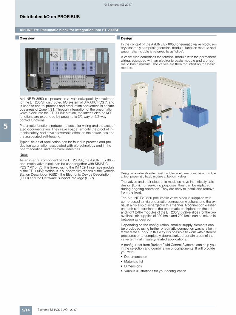
5/14 Siemens ST PCS 7 AO · 2017
5
Distributed I/O on PROFIBUS
AirLINE Ex: Pneumatic block for integration into ET 200iSP
■ Overview
AirLINE Ex 8650 is a pneumatic valve block specially developed for the ET 200iSP distributed I/O system of SIMATIC PCS 7, and is used to control process and production sequences in hazard-ous areas of Zone 1/21. Through integration of the pneumatic valve block into the ET 200iSP station, the latter's electric I/O functions are expanded by pneumatic 3/2-way or 5/2-way control functions.
Pneumatic functions reduce the costs for wiring and the associ-ated documentation. They save space, simplify the proof of in-trinsic safety, and have a favorable effect on the power loss and the associated self-heating.
Typical fields of application can be found in process and pro-duction automation associated with biotechnology and in the pharmaceutical and chemical industries.
Note:
As an integral component of the ET 200iSP, the AirLINE Ex 8650 pneumatic valve block can be used together with SIMATIC PCS 7 V7 or V8. It is linked using the IM 152-1 interface module of the ET 200iSP station. It is supported by means of the Generic Station Description (GSD), the Electronic Device Description (EDD) and the Hardware Support Package (HSP).
■ Design
In the context of the AirLINE Ex 8650 pneumatic valve block, ev-ery assembly comprising terminal module, function module and pneumatic module is referred to as "slice".
A valve slice comprises the terminal module with the permanent wiring, equipped with an electronic basic module and a pneu-matic basic module. The valves are then mounted on the basic module.
Design of a valve slice (terminal module on left, electronic basic module at top, pneumatic basic module at bottom, valves)
The valves and their electronic modules have intrinsically safe design (Ex i). For servicing purposes, they can be replaced during ongoing operation. They are easy to install and remove from the front.
The AirLINE Ex 8650 pneumatic valve block is supplied with compressed air via pneumatic connection washers, and the ex-haust air is also discharged in this manner. A connection washer on each side terminates the pneumatic backplane on the left and right to the modules of the ET 200iSP. Valve slices for the two available air supplies of 300 l/min and 700 l/min can be mixed in between as desired.
Depending on the configuration, smaller supply elements can be produced using further pneumatic connection washers for in-termediate supply. In this way it is possible to work with different pressures or to completely depressurized certain areas of the valve terminal in safety-related applications.
A configurator from Bürkert Fluid Control Systems can help you in the selection and combination of components. It will provide you with:• Documentation• Materials list• Dimensions• Various illustrations for your configuration
© Siemens AG 2017
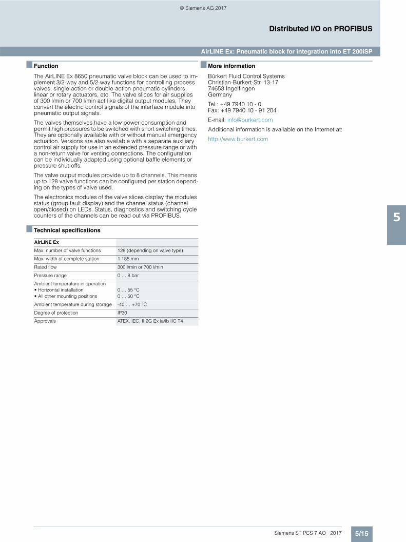
5/15Siemens ST PCS 7 AO · 2017
5
Distributed I/O on PROFIBUS
AirLINE Ex: Pneumatic block for integration into ET 200iSP
■ Function
The AirLINE Ex 8650 pneumatic valve block can be used to im-plement 3/2-way and 5/2-way functions for controlling process valves, single-action or double-action pneumatic cylinders, linear or rotary actuators, etc. The valve slices for air supplies of 300 l/min or 700 l/min act like digital output modules. They convert the electric control signals of the interface module into pneumatic output signals.
The valves themselves have a low power consumption and permit high pressures to be switched with short switching times. They are optionally available with or without manual emergency actuation. Versions are also available with a separate auxiliary control air supply for use in an extended pressure range or with a non-return valve for venting connections. The configuration can be individually adapted using optional baffle elements or pressure shut-offs.
The valve output modules provide up to 8 channels. This means up to 128 valve functions can be configured per station depend-ing on the types of valve used.
The electronics modules of the valve slices display the modules status (group fault display) and the channel status (channel open/closed) on LEDs. Status, diagnostics and switching cycle counters of the channels can be read out via PROFIBUS.
■ Technical specifications
■ More information
Bürkert Fluid Control SystemsChristian-Bürkert-Str. 13-1774653 IngelfingenGermany
Tel.: +49 7940 10 - 0Fax: +49 7940 10 - 91 204
E-mail: [email protected]
Additional information is available on the Internet at:
http://www.burkert.com
AirLINE Ex
Max. number of valve functions 128 (depending on valve type)
Max. width of complete station 1 185 mm
Rated flow 300 l/min or 700 l/min
Pressure range 0 … 8 bar
Ambient temperature in operation• Horizontal installation 0 … 55 °C• All other mounting positions 0 … 50 °C
Ambient temperature during storage -40 … +70 °C
Degree of protection IP30
Approvals ATEX, IEC, II 2G Ex ia/ib IIC T4
© Siemens AG 2017
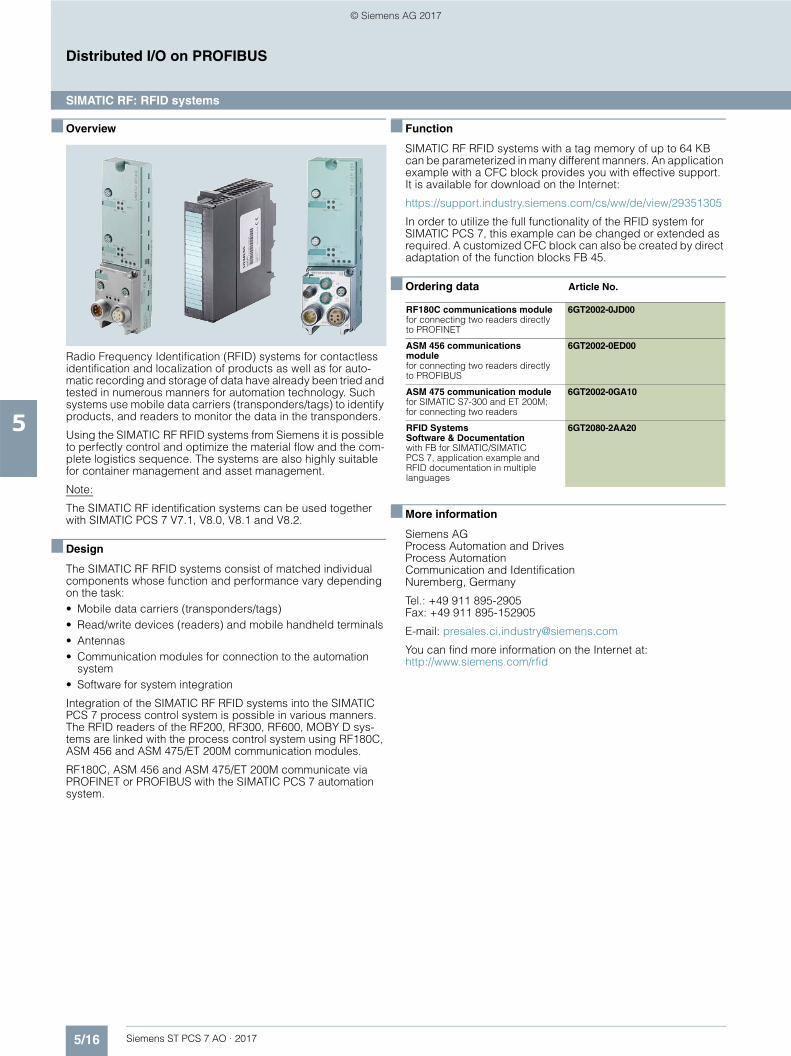
5/16 Siemens ST PCS 7 AO · 2017
5
Distributed I/O on PROFIBUS
SIMATIC RF: RFID systems
■ Overview
Radio Frequency Identification (RFID) systems for contactless identification and localization of products as well as for auto-matic recording and storage of data have already been tried and tested in numerous manners for automation technology. Such systems use mobile data carriers (transponders/tags) to identify products, and readers to monitor the data in the transponders.
Using the SIMATIC RF RFID systems from Siemens it is possible to perfectly control and optimize the material flow and the com-plete logistics sequence. The systems are also highly suitable for container management and asset management.
Note:
The SIMATIC RF identification systems can be used together with SIMATIC PCS 7 V7.1, V8.0, V8.1 and V8.2.
■ Design
The SIMATIC RF RFID systems consist of matched individual components whose function and performance vary depending on the task:• Mobile data carriers (transponders/tags)• Read/write devices (readers) and mobile handheld terminals• Antennas• Communication modules for connection to the automation
system• Software for system integration
Integration of the SIMATIC RF RFID systems into the SIMATIC PCS 7 process control system is possible in various manners. The RFID readers of the RF200, RF300, RF600, MOBY D sys-tems are linked with the process control system using RF180C, ASM 456 and ASM 475/ET 200M communication modules.
RF180C, ASM 456 and ASM 475/ET 200M communicate via PROFINET or PROFIBUS with the SIMATIC PCS 7 automation system.
■ Function
SIMATIC RF RFID systems with a tag memory of up to 64 KB can be parameterized in many different manners. An application example with a CFC block provides you with effective support.It is available for download on the Internet:
https://support.industry.siemens.com/cs/ww/de/view/29351305
In order to utilize the full functionality of the RFID system for SIMATIC PCS 7, this example can be changed or extended as required. A customized CFC block can also be created by direct adaptation of the function blocks FB 45.
■ Ordering data Article No.
■ More information
Siemens AGProcess Automation and DrivesProcess AutomationCommunication and IdentificationNuremberg, Germany
Tel.: +49 911 895-2905Fax: +49 911 895-152905
E-mail: [email protected]
You can find more information on the Internet at:http://www.siemens.com/rfid
RF180C communications modulefor connecting two readers directly to PROFINET
6GT2002-0JD00
ASM 456 communications modulefor connecting two readers directly to PROFIBUS
6GT2002-0ED00
ASM 475 communication modulefor SIMATIC S7-300 and ET 200M; for connecting two readers
6GT2002-0GA10
RFID Systems Software & Documentationwith FB for SIMATIC/SIMATIC PCS 7, application example and RFID documentation in multiplelanguages
6GT2080-2AA20
© Siemens AG 2017

Siemens ST PCS 7 AO · 2017
66/2 ibaPDA/ibaAnalyzer:
Fault tracking log -recording and analysis
6/4 PM-MAINT: Flexible maintenance managementfor SIMATIC PCS 7
Diagnostics
© Siemens AG 2017

6/2 Siemens ST PCS 7 AO · 2017
6
Diagnostics
ibaPDA/ibaAnalyzer: Fault tracking log - recording and analysis
■ Overview
Process control systems usually feature integrated data acquisi-tion (trending) with relatively slow cycle times of 50 ms or more. In addition, examination of the collected data for troubleshooting and process analysis is often insufficiently supported in trend-ing. However, high-cycle, ideally cycle-precise, continuous re-cording of measured values is required to detect sporadic dis-turbances and programming errors in the CPUs. A convenient measured data acquisition system is provided by ibaPDA . The measured data collected in this way can be subsequently analyzed offline with the high-performance ibaAnalyzer.
ibaPDA
ibaPDA is a software package for measured data acquisition on a separate recording computer (PC). This measured data acqui-sition system offers various options for high-cycle acquisition of data from the SIMATIC world, e.g.• Cycle-precise coupling of data via bus monitors, e.g.
ibaBM-DP (PROFIBUS bus monitor)), ibaBM-PN (PROFINET bus monitor) or via CP 1616 (PROFINET connection)
• Software-based interfaces, e.g. ibaPDA-Interface-PLC-Xplorer for communication with the CPUs of the automation systems via MPI, CP/PG or Ethernet-TCP/IP interface
Due to the various interfaces to a wide variety of automation and bus systems, higher-level data acquisition with uniform acquisi-tion time can also be realized in systems with heterogeneous au-tomation technology.
Using a recording computer, digital and/or analog signals can be recorded at rate down to 1 ms, or even down to 10 μs when the appropriate hardware is used.
On the recording computer, the measured data can be ac-cessed and selected online with ibaPDA-Request-S7 without having to re-program or shut down the CPU of the automation system.
ibaAnalyzer
The signals recorded centrally with ibaPDA are stored in files and can be analyzed from any number of workstations using the freeibaAnalyzer software package.
The supplementary ibaAnalyzer-DB package permits the user-friendly further processing of the recorded data with database support. Recorded data can be written to various databases (e.g. Microsoft SQL Server, Microsoft Access, Oracle) and read again according to selectable query criteria.
Note:
ibaPDA and ibaAnalyzer can be used together with SIMATIC PCS 7 V7.1, V8.0, V8.1 and V8.2.
■ Function
ibaPDA• Simple user interface with online signal visualization• Client-Server architecture with multiple clients• Client can be integrated in the OS visualization via ActiveX
based on the .NET compatibility• Numerous display options for measured data e.g. trend, oscil-
loscope, FFT, digital meter• Central configuration dialog with flexible modular structure
and integrated online diagnostics• Built-in OPC server and OPC client functionalities• Virtual signals (formula editor)• Signal groups• Technostrings for recording asynchronous, non-cyclic data,
e.g. batch numbers, setpoints• Combination with ibaCapture CAM/HMI for synchronous
acquisition of camera images and HMI screen data• Staggered licensing model based on the number of
detectable signals (64, 256, 1024, 2048, unlimited)• Several recordings in parallel (expandable)• Complex trigger conditions for data recording• Recording with ibaHD server as an endless strip chart
recorder• Digital output signals (alarm messages) also per TCP/IP• E-mail notifications• Time synchronization via DCF77, PTP (IEEE 1588), IEC 1131• Multi-station operation with several ibaPDA systems
Systematic overview
ibaAnalyzeribaPDA
Ethernet/PROFIBUS/PROFINET
ibaAnalyzer
ibaAnalyzeribaPDA
remote
© Siemens AG 2017

6/3Siemens ST PCS 7 AO · 2017
6
■ Function (continued)
Diagnostics
ibaPDA/ibaAnalyzer: Fault tracking log - recording and analysis
ibaAnalyzer• Graphic user interface with intuitive operation• Automatic scaling• Report generator for automatic generation of graphic and
tabular reports in various formats (PDF, HTML etc.)• Powerful mathematical formulae and operations• Views: Y/T, X/Y, FFT, Y/length, 2D plan, 3D false colors and
3D grid• Mathematically generated "virtual signals"• Graphical digital filter editor• Data export in ASCII format• Automatic presentation of measurement files (slide show)• Generation of analysis guidelines for use on several
measurement files• Combination of signals on a shared scale or on different
scales• Simultaneous consideration of analog and digital signals• X/Y zoom, infinitely variable• Special functions for length representations
ibaAnalyzer-DB• Data extraction of time-based and/or length-based
measurement segments via ODBC in a database (e.g. Microsoft SQL Server, Microsoft Access, Oracle)
• Database query wizard (Query Builder)• Database analysis with full scope of ibaAnalyzer instructions
ibaPDA-Request-S7• Modifying the measurement data to be recorded without
making changes on the CPU• ibaPDA integration via PROFIBUS DP slaves or PROFINET
devices with the bus monitors ibaBM-DP or ibaBM-PN• Optional online access to all operands of the S7-CPUs• Cycle-precise acquisition of measurement data
ibaPDA-Interface-PLC-Xplorer• ibaPDA interface to the automation system's CPU via MPI,
CP/PG or Ethernet TCP/IP• Optional online access to all operands and symbols of the
S7-CPUs• Output of measured data via the selected communication
connection (MPI, CP/PG or Ethernet TCP/IP)
Operating system platforms for all program packages• Windows 7 32/64-bit• Windows Server 2008• Windows Server 2008 R2• Windows 8 32/64-bit• Windows 8.1 32/64-bit• Windows Server 2012• Windows Server 2012 R2• Windows 10 32/64-bit
■ More information
Iba AG Königswarterstraße 4490762 FürthGermany
Tel.: +49 911-97282-0Fax: +49 911-97282-33
E-mail: [email protected]
Additional information is available on the Internet at:
www.iba-ag.com
© Siemens AG 2017

6/4 Siemens ST PCS 7 AO · 2017
6
Diagnostics
PM-MAINT: Flexible maintenance management for SIMATIC PCS 7
■ Overview
PM-MAINT is a sector/technology-independent maintenance management system for inspection, servicing and maintenance of production plants, and is primarily designed for preventive, performance-dependent maintenance. With the objective of maximizing plant availability, PM-MAINT uses the performance data or calendar intervals to generate predictive planning of maintenance measures. PM-MAINT determines the optimum time with regard to production and maintenance. Whereas pre-maturely conducted inspections and servicing shorten the inter-vals and thus increase the maintenance costs, and delayed im-plementation can result in production losses with high repair and downtime costs.
PM-MAINT is linked to the automation level of the process control system via the SIMATIC PCS 7 operator system or per OPC. With its numerous import and export options, it is an ideal supplement for the SIMATIC PCS 7 Maintenance Station.
Note:
The maintenance management system, PM-MAINT, can be use in plants in combination with SIMATIC PCS 7 V7.1, V8.0, V8.1 and V8.2.
■ Design
Example configuration of PM-MAINT in a client/server architecture
PM-MAINT is scalable, and grows with your requirements. It can be used as a local single-user system or also as a distributed multi-user system in a client/server architecture. PM-MAINT can be installed in addition to the SIMATIC PCS 7 OS software on an operator station of version Single Station, Server, or Client.
The PM-MAINT system software is structured as follows:• Type S for Single Station (single-user system) or Server
(multi-user system)• Type C for Client (multi-user system)
PM-MAINT supports the operating systems Windows 7, Windows 8.1, Windows 10, Windows Server 2008 R2 andWindows Server 2012 R2.
G_P
CS
7_X
X_0
0242
MaintenancePM-MAINTClient
ProductionWinCC/PCS 7+ PM-MAINT
Server
Plant bus
Plant 1 Plant x
Plant bus
PM-MAINTClient
PM-MAINTServer
© Siemens AG 2017

6/5Siemens ST PCS 7 AO · 2017
6
Diagnostics
PM-MAINT: Flexible maintenance management for SIMATIC PCS 7
■ Function
PM-MAINT permits mapping of the hierarchical plant structure of the company down to the level of the smallest units for mainte-nance. Maintenance jobs can be created for each maintenance object.
Maintenance planning and activation
In the case of performance-dependent maintenance, PM-MAINT utilizes operating hours and switching cycles from the current process data to calculate the recommended mainte-nance dates. When these dates are reached, PM-MAINT auto-matically creates the maintenance job. Additional options for creating maintenance jobs are process events or calendar inter-vals (days, weeks, months, quarters, years).
Assignment of documents
Any documents can be added as supplementary information to each maintenance object or job in the object tree, e.g.• Dimension drawings• Technical specifications• Maintenance information
Job recording/checklists
Maintenance jobs can be recorded manually or automatically. These reports are then used by the maintenance personnel as a checklist. Lists with ordering data for material requirements plan-ning are additionally available for printing depending on the job. Processing of measures can also be documented in a report.
Material and personnel assignment
The required material and personnel resources can be assigned to the maintenance jobs. The materials and working hours actu-ally required can then be entered in the feedback relating to maintenance activities.
Archiving and analysis
All maintenance activities are saved in an archive which is per-manently evaluated to achieve a continuous improvement in maintenance procedures. Unexpected maintenance jobs can be recorded manually or by means of the SIMATIC PCS 7 Main-tenance Station, and integrated into the long-term archiving.
■ Ordering data Article No.
■ More information
Siemens AGSiemens GermanyMannheim branch
Process Industries and DrivesWinCC Competence Center Mannheim
Tel.: +49 621 456-3269Fax: +49 621 456-3334
E-mail: [email protected]
You can find additional information on the Internet at:www.siemens.com/process-management
PM-MAINT system software for SIMATIC PCS 7 V7 and V8
PM-MAINT system softwareType SFor a single station (single-user system) or a server (multi-user system)
Engineering and runtime software, software class A, 2 languages (German, English), single license for 1 installation
Delivery package: Software and electronic documentation on DVD, dongle (hard lock), and certificate of license
9AE7104-2SS30-1AA0
PM-MAINT system software Type CFor a client (multi-user system)
Engineering and runtime software, software class A, 2 languages (German, English), single license for 1 installation
Delivery package: Software and electronic documentation on DVD, dongle (hard lock), and certificate of license
9AE7104-4SC00-1AA0
© Siemens AG 2017

6/6 Siemens ST PCS 7 AO · 2017
6
Diagnostics
Notes
© Siemens AG 2017

Siemens ST PCS 7 AO · 2017
77/2 Telecontrol with SIPLUS RIC7/2 Telecontrol connection to control center in
SIMATIC PCS 77/7 Telecontrol connection to third-party
control center
Telecontrol
© Siemens AG 2017

7/2 Siemens ST PCS 7 AO · 2017
7
TelecontrolTelecontrol with SIPLUS RIC
Telecontrol connection to control center in SIMATIC PCS 7
■ Overview
Example of complex TCP/IP-based WAN with cable and wireless networks
The telecontrol communication between a telecontrol center in-tegrated in SIMATIC PCS 7 and its outstations (Remote Terminal Units) is based on SIPLUS RIC libraries and is possible via serial communication links as well as via Ethernet TCP/IP communica-tion links – with telecontrol protocol option• IEC 60870-5-104 (Ethernet TCP/IP)• IEC 60870-5-101 (serial)
Advantages of the TCP/IP-based connection through IEC 60870-5-104 are simultaneous data transfer to multiple devices and diagnostics using SIMATIC Manager.
Security mechanisms are not defined in the application area of IEC 60870-5-104. Therefore, encryption of the user data (data integrity) and authentication of the communication partners must be implemented separately (Industrial Security).
The telecontrol center integrated with SIMATIC PCS 7 TeleControl into the operator system of the process control system is the master during telecontrol communication. The Remote Terminal Units (RTUs) are slaves of the control center on the one hand, but can additionally function as masters for subor-dinate outstations with the following protocols:• IEC 60870-5-104 (Ethernet TCP/IP)• IEC 60870-5-101 (serial)• IEC 60870-5-103 (serial)
Note:
Telecontrol integration into the SIMATIC PCS 7 process control system using SIPLUS RIC libraries with IEC 60870-5-104 or IEC 60870-5-101 protocols requires one of the following soft-ware combinations:• SIMATIC PCS 7 V8.2 and SIMATIC PCS 7 TeleControl V8.2• SIMATIC PCS 7 V8.1 and SIMATIC PCS 7 TeleControl V8.1• SIMATIC PCS 7 V8.0+SP1 and SIMATIC PCS 7 TeleControl
V8.0+SP1/SP2• SIMATIC PCS 7 V8.0 incl. Update 1 and SIMATIC PCS 7
TeleControl V8.0• SIMATIC PCS 7 V7.1 and SIMATIC PCS 7 TeleControl V7.1
Control centerSIMATIC PCS 7 TeleControl
UMTS/GPRSwireless network
DSL router
SIPLUS RIC library with SIMATIC S7-1500
Complex network structure, with a combination of various topologies and media
SIPLUS RIC librarywith SIMATIC ET 200SP
SIPLUS RIC librarywith SIMATIC S7-400
SIPLUS RIC librarywith SIMATIC S7-1500
SIPLUS RIC librarywith SIMATIC ET 200SP
2-wire max. 1 000 m
GPS satellite
SIPLUS RIC library with SIMATIC S7-300
SICLOCKTC100
SCALANCE S623Ethernet
IEC 60870-5-104 IEC 60870-5-104
IEC 60870-5-104
SICLOCKGPS2000
SCALANCEM875
Internet
IEC 60870-5-104
G_P
CS
7_X
X_0
0563
© Siemens AG 2017

7/3Siemens ST PCS 7 AO · 2017
7
TelecontrolTelecontrol with SIPLUS RIC
Telecontrol connection to control center in SIMATIC PCS 7
■ Design
Remote terminal units (RTUs)
RTUs with hardware controller
In combination with a type-specific SIPLUS RIC library, hardware controllers from the following product series can be used asremote stations in telecontrol applications with IEC 60870-5-101 (serial) or IEC 60870-5-104 (Ethernet TCP/IP) telecontrol protocols:
Comparable controllers from the SIPLUS extreme product spectrum can be used for especially demanding environmental conditions. Information about the controller from the SIPLUS extreme product spectrum can be found in ST 70 catalog and on the Internet at:www.siemens.com/siplus
Controller for use as a RTU – parameters and scaling
Controller Number of I/Os(dependent on CPU size, protocol type, and application)
Number of information or data points
Integrated in SIMATIC ET 200S 30 … 200 I/Os Approx. 200
Integrated in SIMATIC ET 200SP 30 ... 500 I/Os Approx. 500
SIMATIC S7-300/S7-300F 100 … 2 000 I/Os Approx. 2 000
SIMATIC S7-400/S7-400F 500 … 5 000 I/Os Approx. 5 000
SIMATIC S7-400H/S7-400FH 500 … 5 000 I/Os Approx. 5 000
SIMATIC S7-1500 200 ... 5 000 I/Os Approx. 5 000
RTU type ET 200S S7-300 S7-400
CPU IM 151-7
IM 151-7F
IM 151-8
IM 151-8F
CPU 314C-2 PN/DP
CPU 315-2 PN/DP
CPU 315F-2 PN/DP
CPU 317-2 PN/DP
CPU 317F-2 PN/DP
CPU 319-3 PN/DP
CPU 319F-3 PN/DP
CPU 412-2 PN
CPU 412-5H PN/DP
CPU 414-3 PN/DP
CPU 414-5H PN/DP
CPU 416-3 PN/DP
CPU 416-5H PN/DP
CPU 417-5H PN/DP
CPU 410-5H Process Automation
Work memory 128/192 KB 192/256 KB 192 KB 384/512 KB 1024/1536 KB
2048/2560 KB
1 MB 4 MB 16 MB 32 MB
Data memory, non-volatile
64 KB 64 KB 64 KB 128 KB 256 KB 700 KB – – – –
Data memory, volatile
64/128 KB 128/192 KB 128 KB 256/384 KB 768/1280 KB 1348/1860 KB
– – – –
Code – – – – – – 512 KB 2 MB 8/6 MB 16 MB
Data – – – – – – 512 KB 2 MB 8/10 MB 16 MB
SIPLUS RIC program
64 KB 64 KB 64 KB 64 KB 64 KB 64 KB 64 KB 64 KB 64 KB 64 KB
Buffer (volatile) 64 KB 64 KB 64 KB 192 KB 704 KB 1024 KB – – – –
Buffer (message frames)
Approx. 1 500
Approx. 1 500
Approx. 1 500
Approx. 4 500
Approx. 16 000
Approx. 24 000
Approx. 4 500
Approx. 12 000
Approx. 24 000
Approx. 24 000
Recommended memory card
512 KB 512 KB 512 KB 512 KB 2 MB 2 MB – – – –
Number of Ether-net interfaces on CPU
0 1 1 1 1 1 1 1 1 1/2
Number of TCP/IP connections
– 8 8 8 16 32 46 62 94 118
Recommended number of infor-mation or data points
200 200 200 1 000 2 000 5 000 1 000 2 000 5 000 5 000
© Siemens AG 2017

7/4 Siemens ST PCS 7 AO · 2017
7
■ Design (continued)
TelecontrolTelecontrol with SIPLUS RIC
Telecontrol connection to control center in SIMATIC PCS 7
For detailed technical information and ordering data for the RTU types listed in the table, refer to the ST 70 and ST PCS 7 catalogs.
RTUs with software controller
In combination with a SIPLUS RIC library, SIMATIC PC-based systems with a software controller (SIMATIC WinAC RTX, SIMATIC S7-1500 Software Controller or SIMATIC ET 200SP Open Controller) are also suitable as remote stations in telecon-trol applications with remote control protocol IEC 60870-5-101 (serial) or IEC-60870-5-104 (Ethernet TCP/IP).
SIPLUS RIC Libraries
The SIPLUS RIC libraries for IEC 60870-5-101 and -104 proto-cols are delivered as master and slave. The library for the IEC 60870-5-103 protocol is only available as a master.
The product package for all SIPLUS RIC libraries include a CD with software and documentation and a certificate of license for all protocols and interfaces. With SIPLUS RIC libraries for SIMATIC ET 200S, SIMATIC ET 200SP, SIMATIC S7-300 and SIMATIC S7-1500 RTU types, a memory card (MMC/SMC) is also included. The product variations offered for a hardware controller type are distinguished by the storage capacity of the memory card.
A license is required for each of the two CPUs when redundant SIMATIC S7-400 systems are used.
Depending on the RTU type, activation can be performed using either the supplied memory card (ET 200S, ET 200SP, S7-300, S7-1500) or via the e-mail address [email protected] (S7-400). All libraries of the respective series are activated.
RTU type ET 200SP S7-1500
CPU CPU 1510-1 PN
CPU 1510F-1 PN
CPU 1512-1 PN
CPU 1512F-1 PN
CPU 1511-1 PN
CPU 1511F-1 PN
CPU 1513-1 PN
CPU 1513F-1 PN
CPU 1515-2 PN
CPU 1515F-2 PN
CPU 1516-3 PN/DP
CPU 1516F-3 PN/DP
CPU 1517-3 PN/DP
CPU 1517F-3 PN/DP
CPU 1518-4 PN/DP
CPU 1518F-4 PN/DP
Work memory 0.85/0.9 MB 1.3 MB 1.15/1.225 MB 1.8/1.95 MB 3.5/3.75 MB 6/6.5 MB 10/11 MB 24/26 MB
Data memory, non-volatile
– – – – – – – –
Data memory, volatile
– – – – – – – –
Code 0.1/0.15 MB 0.2/0.3 MB 0.15/0.225 MB 0.3/0.45 MB 0.5/0.75 MB 1/1.5 MB 2/3 MB 4/6 MB
Data 0.75 MB 1 MB 1 MB 1.5 MB 3 MB 5 MB 8 MB 20 MB
SIPLUS RIC program
0.096 MB 0.096 MB 0.096 MB 0.096 MB 0.096 MB 0.096 MB 0.096 MB 0.096 MB
Buffer (volatile) – – – – – – – –
Buffer (message frames)
Approx. 3 000 Approx. 6 000 Approx. 6 000 Approx. 12 000 Approx. 24 000 Approx. 24 000 Approx. 24 000 Approx. 24 000
Recommended memory card
12 MB 12 MB 12 MB 12 MB 24 MB 24 MB 256 MB 256 MB/ 2 GB
Number of Ether-net interfaces on CPU
1 1 1 1 2 2 2 3
Number of TCP/IP connections with-out/with CPs
54 78 54/86 78/118 108/192 118/246 150/310 182/374
Recommended number of informa-tion or data points
200 800 200 1 000 1 000 2 000 5 000 5 000
© Siemens AG 2017

7/5Siemens ST PCS 7 AO · 2017
7
■ Design (continued)
TelecontrolTelecontrol with SIPLUS RIC
Telecontrol connection to control center in SIMATIC PCS 7
Communication/network components
Communication/network components from the IK PI Catalog supplement the product range for configuration of IEC 60870-5-101/-104 telecontrol applications using SIPLUS RIC libraries such as:• TCP/IP converter and serial modem module• Mobile radio components• Industrial Ethernet switches, TCP/IP routers, and media
converters• SCALANCE W industrial wireless LAN components• SCALANCE S industrial security modules, e.g. S612• Dedicated line accessories• Connecting cables
Network topologies
For the configuration of complete, hierarchical telecontrol net-works, it is possible to implement basic topology forms such as point-to-point, multipoint, star and ring in various media forms and to combine them depending on the infrastructure require-ments.
Examples of media forms• Private networks
- Radio- Dedicated line via fiber-optic cable or via modem- Ethernet network, e.g. with SCALANCE X and fiber-optic
cables- WLAN, e.g. with SCALANCE W
• Public networks- GPRS- EGPRS- UMTS- LTE- DSL- Satellite communication, e.g. Inmarsat
Redundancy
Telecontrol communication availability can be improved by connecting the RTU to the control center in the process control system via two transmission paths. The two redundant transmis-sion paths can be based on the same or different telecontrol protocols.
The use of redundant RTUs of type S7-400H (high availability) or S7-400FH (safety-related and high availability) results in further options for increasing the availability, e.g. redundant design of telecontrol communication, fieldbus and process I/O. As a result of the seamless integration of the telecontrol system in the SIMATIC PCS 7 process control system, its implementation depends on the redundancy concept of the complete system (see example of redundant telecontrol configuration with the IEC 60870-5-101/104 telecontrol protocols).
Example of redundant telecontrol configuration with the IEC 60870-5-101/-104 telecontrol protocols
Connection of SIPROTEC protection devices
SIPLUS RIC IEC 60870-5-103 Master can also be used to con-nect protection devices such as SIPROTEC via SIMATIC PCS 7 TeleControl. The RTU then serves as a converter between the IEC 60870-5-103 protection data protocol and the IEC 60870-5-101 or IEC 60870-5-104 protocol.
Compared to PROFIBUS DP interfacing of the protective equip-ment, this configuration provides the following advantages:• Longer distances achievable• High precision time stamps are transferred from the protective
equipment to the control system
■ Function
Telecontrol communication with SIPLUS RIC is characterized by the following features:• Uniform configuration using the SIMATIC Manager (except for
the controller SIMATIC S7-1500 and ET 200SP and SIMATIC S7-1500 Software Controller and SIMATIC ET 200SP Open Controller)
• Event-driven data transfer• Monitored output of commands for reliable detection of
malfunctions• Diagnostics functions for rapid tracing and elimination of faults• High availability thanks to redundant data communication
Additional special features of the IEC 60870-5-101 and IEC 60870-5-104 telecontrol protocols include:• Time stamping for data acquisition in the outstation• Data buffering for bridging communication interruptions
(for RTU-specific information on buffering, see tables in the "Remote Terminal Units" section)
• Time synchronization via the control center
SIMATIC PCS 7 OS clients
Control center SIMATIC PCS 7 TeleControl OSwith redundant servers
Redundant system bus
Terminal bus
IEC 60870-5-101 redundant
IEC 60870-5-104 redundant
TCP/IP to serial converter
RTU S7-400HRTU S7-400H with PN in CPU or CP 443
TCP/IP WAN router
ET 200Mredundant
ET 200M redundant with 2 x CP 341 G
_PC
S7_
XX
_002
74
© Siemens AG 2017
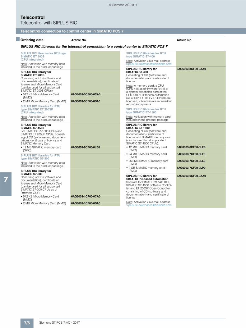
7/6 Siemens ST PCS 7 AO · 2017
7
TelecontrolTelecontrol with SIPLUS RIC
Telecontrol connection to control center in SIMATIC PCS 7
■ Ordering data Article No. Article No.
SIPLUS RIC libraries for the telecontrol connection to a control center in SIMATIC PCS 7
SIPLUS RIC libraries for RTU type SIMATIC ET 200S (CPU integrated)
Note: Activation with memory card included in the product package
SIPLUS RIC library for SIMATIC ET 200SConsisting of CD (software and documentation), certificate of license and Micro Memory Card (can be used for all supported SIMATIC ET 200S CPUs):• 512 KB Micro Memory Card
(MMC)6AG6003-5CF00-0CA0
• 2 MB Micro Memory Card (MMC) 6AG6003-5CF00-0DA0
SIPLUS RIC libraries for RTUtype SIMATIC ET 200SP (CPU integrated)
Note: Activation with memory card included in the product package
SIPLUS RIC library for SIMATIC S7-1500For SIMATIC S7-1500 CPUs and SIMATIC ET 200SP CPUs, consist-ing of CD (software and documen-tation), certificate of license and SIMATIC Memory Card• 12 MB SIMATIC memory card
(SMC)6AG6003-8CF00-0LE0
SIPLUS RIC libraries for RTU type SIMATIC S7-300
Note: Activation with memory card included in the product package
SIPLUS RIC library for SIMATIC S7-300Consisting of CD (software and documentation), certificate of license and Micro Memory Card (can be used for all supported SIMATIC S7-300 CPUs as of firmware V2.6):• 512 KB Micro Memory Card
(MMC)6AG6003-1CF00-0CA0
• 2 MB Micro Memory Card (MMC) 6AG6003-1CF00-0DA0
SIPLUS RIC libraries for RTU type SIMATIC S7-400
Note: Activation via e-mail [email protected]
SIPLUS RIC library for SIMATIC S7-400Consisting of CD (software and documentation) and certificate of license
Note: A memory card, a CPU (CPU 41x as of firmware V4.x) or a system expansion card of the CPU 410-5H Process Automation (as of SIPLUS RIC V1.6 UPD3) are licensed; 2 licenses are required for redundant systems.
6AG6003-3CF00-0AA0
SIPLUS RIC libraries for RTU type SIMATIC S7-1500
Note: Activation with memory card included in the product package
SIPLUS RIC library for SIMATIC S7-1500Consisting of CD (software and documentation), certificate of license and SIMATIC memory card (can be used for all supported SIMATIC S7-1500 CPUs):• 12 MB SIMATIC memory card
(SMC)6AG6003-8CF00-0LE0
• 24 MB SIMATIC memory card (SMC)
6AG6003-7CF00-0LF0
• 256 MB SIMATIC memory card (SMC)
6AG6003-7CF00-0LL0
• 2 GB SIMATIC memory card (SMC)
6AG6003-7CF00-0LP0
SIPLUS RIC library for SIMATIC PC-based automationSoftware for SIMATIC WinAC RTX, SIMATIC S7-1500 Software Control-ler and ET 200SP Open Controller, consisting of CD (software and documentation) and certificate of license
Note: Activation via e-mail address [email protected]
6AG6003-0CF00-0AA0
© Siemens AG 2017

7/7Siemens ST PCS 7 AO · 2017
7
TelecontrolTelecontrol with SIPLUS RIC
Telecontrol connection to third-party control center
■ Overview
SIMATIC PCS 7 automation systems can also communicate with a remote third-party control center by means of the telecontrol protocol IEC 60870-5-101 (serial) or IEC 60870-5-104 (TCP/IP).
The IEC 60870-5-101 protocol permits use of classic WAN-connections over modems and dedicated lines. The IEC 60870-5-104 protocol supports TCP/IP-based WAN-connections like Internet/DSL, GPRS or LTE.
■ Application
Possible fields of application include:• Interfacing of power plant automation based on SIMATIC
PCS 7 to network control centers for power distribution• Interfacing of pumping and compressor stations automated
using SIMATIC PCS 7 to higher-level control centers for gas, oil or water pipelines
■ Design
Notes:
With the telecontrol configurations described below for connec-tion of SIMATIC PCS 7 automation systems to a third-party con-trol center, use of the SIPLUS RIC for SIMATIC S7-400 library is independent of SIMATIC PCS 7 TeleControl.
The materials required to design a telecontrol link, e.g. TCP/IP router, CP 443-1, CP 441-1, CP 341, dedicated line modem, cables etc. are accessories which are not included in this cata-log. For additional information and ordering data, see IK PI and ST 70 catalogs
Telecontrol connection for single SIMATIC PCS 7 automation systems (single station)
Configuration examples of the telecontrol connection of SIMATIC PCS 7 automation systems of single station design with the IEC 60870-5-101 and IEC 60870-5-104 telecontrol protocols
Depending on the protocol, the following automation system connection options can be used for communication: • CP 441 (IEC 60870-5-101)• PN interface in CPU/CP 443-1 (IEC 60870-5-104)
In the SIMATIC PCS 7 automation system, additive driver blocks from the SIPLUS RIC library for SIMATIC S7-400 adapt the interface for communication using the IEC 60870-5-101 or IEC 60870-5-104 standardized protocols. Configuration is performed using the SIMATIC Manager as usual for SIMATIC PCS 7. This equally applies to automation systems designed as single station or redundant station.
SIMATIC PCS 7 operator systemSingle station orclient/server configuration
Supervisory Control System (telecontrol center) separate from SIMATIC PCS 7
Industrial Ethernet plant busDedicated line modem
Third-party system:SupervisoryControl System
TCP/IProuter
TCP/IProuter
SIMATIC PCS 7automation systems
Dedicatedline modem
Telecontrol networkaccording to IEC 60870-5-101 (WAN)
Telecontrol networkaccording to IEC 60870-5-104 (WAN), e.g. Internet/DSL
PN interface in CPU or CP 443-1
SIPLUS RIC libraryfor SIMATIC S7-400
SIPLUS RIC libraryfor SIMATIC S7-400 C
P 4
41-1
G_P
CS
7_X
X_0
0177
© Siemens AG 2017

7/8 Siemens ST PCS 7 AO · 2017
7
■ Design (continued)
TelecontrolTelecontrol with SIPLUS RIC
Telecontrol connection to third-party control center
Telecontrol connection for redundant SIMATIC PCS 7 automation systems (redundant station)
Redundant configuration with IEC 60870-5-101 telecontrol protocol (serial)
Configuration example of the telecontrol connection of redundant SIMATIC PCS 7 AS with the IEC 60870-5-101 telecontrol protocol
• The control center is linked via a serial telecontrol connection with IEC 60870-5-101 protocol to a CP 340 or CP 341 in an ET 200M station of the SIMATIC PCS 7 system.
• If the master system fails, the standby system of the redundant automation system takes over data exchange with the control center bumpless via the CP 341 in the ET 200M station.
• Failure of the master system can be signaled to the control center.
SIMATIC PCS 7 operator systemSingle station orclient/server configuration
Supervisory Control System (telecontrol center) separate from SIMATIC PCS 7
Industrial Ethernet plant busDedicated line modem
Third-party system:SupervisoryControl System
Dedicatedline modem
SIPLUS RIC libraryfor SIMATIC S7-400Telecontrol network
according to IEC 60870-5-101 (WAN)
SIMATIC PCS 7 AS Redundancy Station
G_P
CS
7_X
X_0
0178
© Siemens AG 2017

7/9Siemens ST PCS 7 AO · 2017
7
■ Design (continued)
TelecontrolTelecontrol with SIPLUS RIC
Telecontrol connection to third-party control center
Redundant configuration with IEC 60870-5-104 telecontrol protocol (TCP/IP)
Configuration example of the telecontrol connection of redundant SIMATIC PCS 7 AS with the IEC 60870-5-104 telecontrol protocol
• The control center is linked via a TCP/IP-based WAN to the SIMATIC PCS 7 system bus.
• The control center establishes a TCP/IP connection to an AS subsystem with each of the two communication interfaces via which the redundant automation system is integrated into the system bus.
• The control center starts the IEC 60870-5-104 telecontrol protocol via the TCP/IP connection to the master system and monitors the TCP/IP connection to the standby system using test frames.
• If the master system fails, the control center signals the associated connection as being faulty, and starts the IEC 60870-5-104 telecontrol protocol via the TCP/IP connection to the standby system. It then attempts to reestablish the faulty connection.
■ Ordering data Article No. ■ More information
As a specialist for complete solutions in the product and system business, we would be pleased to advise you concerning gen-eration of an individual configuration and the selection of acces-sories. If required, we can also supply preconfigured bundles or turnkey outstations installed in wall enclosures, cabinets or con-tainers. Contact address for quotation and consulting:
Siemens AGBreslauer Str. 590766 FürthGermany
Tel.: +49 911 750 - 4790Fax: +49 911 750 - 9917
E-mail: [email protected]
You can find additional information on the Internet at:www.siemens.com/siplus-ric
Telecontrol networkaccording to
IEC 60870-5-104 (WAN)
SIMATIC PCS 7 operator systemSingle station orclient/server configuration
Supervisory Control System (telecontrol center) separate from SIMATIC PCS 7
Industrial Ethernet plant busTCP/IP router
TCP/IP router
Third-party system:SupervisoryControl System
PN interface in CPU or CP 443-1
SIPLUS RIC libraryfor SIMATIC S7-400
SIMATIC PCS 7 AS Redundancy Station
G_P
CS
7_X
X_0
0179
SIPLUS RIC libraries for RTU type SIMATIC S7-400
Note: Activation via e-mail address [email protected]
SIPLUS RIC library forSIMATIC S7-400Consisting of CD (software and documentation) and certificate of license
Note: A memory card, a CPU (CPU 41x as of firmware V4.x) or a system expansion card of the CPU 410-5H Process Automation (as of SIPLUS RIC V1.6 UPD3) are licensed; 2 licenses are required for redundant systems.
6AG6003-3CF00-0AA0
© Siemens AG 2017

7/10 Siemens ST PCS 7 AO · 2017
7
Telecontrol
Notes
© Siemens AG 2017

Siemens ST PCS 7 AO · 2017
99/2 SIMATIC Energy Manager PRO
9/6 LIBRARY PAC/3WL/3VA SIMATIC PCS 7
Energy management
© Siemens AG 2017

9/2 Siemens ST PCS 7 AO · 2017
9
Energy management
SIMATIC Energy Manager PRO
■ Overview
SIMATIC Energy Manager PRO energy management system
With SIMATIC Energy Manager PRO, a modular, non-sector-specific energy management and operating information system is available for industrial firms.
SIMATIC Energy Manager PRO forms the basis for cost-effective energy management to reduce energy costs and increase energy efficiency.
Released SIMATIC software:• SIMATIC WinCC V7.3 SE, SIMATIC WinCC V7.4• SIMATIC WinCC V7.2• SIMATIC WinCC RT Professional V13, SIMATIC WinCC RT
Professional V14• SIMATIC PCS7 V8.1, SIMATIC PCS7 V8.2• SIMATIC NET V12 SP2
Note:
SIMATIC B.Data V6.0 has been completely updated and trans-ferred to the SIMATIC Energy Manager PRO V7.0. This means, among other things, that a dynamic widget-based web dash-board, dynamic web visualization, and seamless interfacing to the SIMATIC Energy Suite is now available.
Upgrading from SIMATIC B.Data 6.0 to SIMATIC Energy Manager PRO 7.0 is possible at any time and is included in the SIMATIC B.Data SUS.
■ Benefits
Advantages:• Company-wide transparency thanks to consistent energy and
material balancing of power generation and consumption plants
• Energy costs allocated according to the costs-by-cause principle and transfer to the billing system (e.g. SAP R/3 CO)
• Characteristic values for substantiated statements on increasing the efficiency of power generation systems and consumers
• Planning reliability thanks to production-related load and demand forecasts
• Support of purchasing with cost-optimized energy procurement
• Fulfilment of legal obligations for monitoring and reporting on greenhouse gas emissions (CO2 emissions)
• Reduction of workload by automatically generating internal and external energy reports
• Support of customers in the continuous improvement of energy efficiency (e.g. ISO 50001) by integrated project management for energy efficiency measures
Management
SIMATIC Energy Manager PRO
SIMATIC Energy Suite
Company-wide energy analytics
Energy efficiency in production
Processing and Monitoring
Measuring
Management Level Economic and Management Level
Production Level
Production Level
Field Level G_S
T80_
XX
_008
74
© Siemens AG 2017

9/3Siemens ST PCS 7 AO · 2017
9
Energy management
SIMATIC Energy Manager PRO
■ Design
SIMATIC Energy Manager PRO V7.0
SIMATIC Energy Manager PRO is delivered as a basic package which can be flexibly expanded by tag packages.• The basic package already contains:
- 50 tags- 1 Energy Manager PRO Acquisition component- 1 Energy Manager PRO Client- 1 Energy Manager PRO Web Client
• Available tag packages:- 50 tags- 100 tags- 250 tags- 500 tags- 1 000 tags- 5 000 tags- 30 000 tags
SIMATIC Energy Manager PRO Software Update Service (SUS)
For each Energy Manager PRO system there is a corresponding SUS (Software Update Service) which is dependent on the number of tags.
The SUS is valid for 1 year. The contract is automatically extended by 1 more year unless canceled 3 months prior to expiration.
SIMATIC Energy Manager PRO expansions
The scope of Energy Manager PRO can be extended with add-on packages:• Energy Manager PRO Web Clients (3, 20 or 60)• Energy Manager PRO Client • Energy Manager PRO Acquisition component• Energy Manager PRO Planning and Forecast
■ Function
Acquisition and pre-processing of energy and operating data• In addition to an interface to the SIMATIC Energy Suite,
SIMATIC Energy Manager PRO also offers the latest interface standards such as WinCC, OPC UA, OPC DA, OPC HDA, MODBUS TCP, ODBC, ASCII and XML
• Preprocessing of energy data in a real-time calculation core that can be freely modeled including a formula editor for defining and configuring new calculation functions (heat calculations for boilers, quality for cogeneration plants, etc.)
• Energy Manager PRO Mobile for mobile recording of energy data including route planning for meter reading operations
• Management and analysis of energy data• Automatic plausibility check and generation of simulated
values • Long-term archive with versioning, compression and consoli-
dation functions• Measured value editor for entering and processing energy
and operating values• Trender for presenting up-to-date (online) and historical load
curves (trends), also for setpoint/actual value analyses• Energy management dashboards for creating cross-company
transparency through visualization of performance indicators and display of Sankey diagrams.
SIMATIC Energy Manager PRO
© Siemens AG 2017

9/4 Siemens ST PCS 7 AO · 2017
9
■ Function (continued)
Energy management
SIMATIC Energy Manager PRO
Energy and material balance
Freely parameterizable balancing of the energy flows of various media such as electricity, heat, gas, steam, and emissions (CO2) in the B.Data Plant Explorer• Calculation of characteristic values (KPIs, efficiency coeffi-
cients, etc.) with direct reference to production (batches, quantities, etc.).
Energy accounting (costs and revenue accounting)
Calculation and allocation/assignment of energy costs to plants and/or customers/cost units in accordance with the costs-by-cause principle. The bottom up (measurement) and top down (allocation) procedures are supported here• Flexible modeling of the hierarchic accounting structures in
the Plant Explorer• Tariff allocation of quantities, flexible price assessment with
tariff and price time series• Transfer of costs/revenues to the ERP system
(e.g. SAP R/3 CO)
Energy planning• Generation of requirement forecasts based on production-
dependent factors (production planning) and basic load profiles (typical days)
Energy reporting• Generation of energy schedules for registering with the
energy suppliers. Energy reporting• Freely parameterizable report generator for creating
balances, protocols, shift logs, bills• Fully automated reporting with task management, e-mail
dispatch and document management• Energy Manager PRO Intranet/Internet Viewer (web client) for
company-wide viewing of reports and results• Information about discrepancies from specified parameters
through KPI warning system
■ Technical specifications
1) If an acquisition computer is installed on a WinCC system, these require-ments must also be complied with.
2) The SIMATIC Energy Manager PRO system for connection to the PCS 7 must always be installed on a separate PC.
Losses
Counter 1 Counter 3
Counter 2
Accounting area (e.g. cost center)
Consumption area (e.g.: building 1)
Factors are based on:• Numbers of employees• Area data• Allocation formula• etc.
100% distribution ensured
Consumption area (e.g.: building 2)
G_S
T80_
XX
_003
80
1 ... n
10% 90%
75% 25%
20% 80%
SIMATIC Energy Manager PRO V7.0
Operating system • Windows Server 2008 R2 (English/German)
• Windows Server 2012 R2(English/German)
• Windows 7 Professional/Ultimate SP1 (English/German)
• Windows 8.1 Pro/Enterprise 64-bit (English/German)
• Windows 10 Pro/Enterprise 64-bit (English/German)
• Minimum of 4 GB RAM
Interface In addition to an interface to WinCC and S7 controllers, Energy Manager PRO also offers the latest interface standards such as OPC DA, OPC HDA, OPC UA, MODBUS TCP, ODBC, ASCII and XML.
WinCC versions 1) • SIMATIC WinCC V7.2, V7.3 SE, V7.4• SIMATIC WinCC RT Professional V13, V14
PCS 7 versions 2) • SIMATIC PCS 7 V8.1• SIMATIC PCS 7 V8.2
© Siemens AG 2017

9/5Siemens ST PCS 7 AO · 2017
9
Energy management
SIMATIC Energy Manager PRO
■ Ordering data Article No. Article No.
1) The tag packages dynamically expand the number of tags. The total number of tags is increased by the value of the tag package in each case.
2) The SUS contract runs for 1 year. The contract is automatically extended by a further year unless canceled 3 months prior to expiration.
For more detailed information, refer to:
www.siemens.com/energymanager
■ More information
Further information can be found on the Internet at:
www.siemens.com/energymanager
SIMATIC Energy Manager PRO V7.0
Standard scope of delivery• SIMATIC Energy Manager PRO in-
cl. 50 tags 1)6AV6372-2DF07-0AX0
• Tag Package 50 1) 6AV6372-2DF07-0CX0• Tag Package 100 1) 6AV6372-2DF07-0DX0• Tag Package 250 1) 6AV6372-2DF07-0EX0• Tag Package 500 1) 6AV6372-2DF07-0FX0• Tag Package 1 000 1) 6AV6372-2DF07-0GX0• Tag Package 5 000 1) 6AV6372-2DF07-0HX0• Tag Package 30 000 1) 6AV6372-2DF07-0JX0
Download• SIMATIC Energy Manager PRO
incl. 50 tags 1)6AV6372-2DF07-0AH0
• Tag Package 50 1) 6AV6372-2DF07-0CH0• Tag Package 100 1) 6AV6372-2DF07-0DH0• Tag Package 250 1) 6AV6372-2DF07-0EH0• Tag Package 500 1) 6AV6372-2DF07-0FH0• Tag Package 1 000 1) 6AV6372-2DF07-0GH0• Tag Package 5 000 1) 6AV6372-2DF07-0HH0• Tag Package 30 000 1) 6AV6372-2DF07-0JH0
SIMATIC Energy Manager PRO V7.0 expansions
Standard scope of delivery• 3 Web Clients 6AV6372-2DF27-0AX0• 20 Web Clients 6AV6372-2DF27-0BX0• 60 Web Clients 6AV6372-2DF27-0CX0• Client 6AV6372-2DF37-0AX0• Planning & Forecast 6AV6372-2DF47-0AX0• Acquisition component 6AV6372-2DF57-0AX0
Download• 3 Web Clients 6AV6372-2DF27-0AH0• 20 Web Clients 6AV6372-2DF27-0BH0• 60 Web Clients 6AV6372-2DF27-0CH0• Client 6AV6372-2DF37-0AH0• Planning & Forecast 6AV6372-2DF47-0AH0• Acquisition component 6AV6372-2DF57-0AH0
SIMATIC Energy Manager PRO SUS 2)
Standard scope of delivery• For max. 100 additional tags
through tag packages 2)6AV6372-2DF00-0DL0
• For max. 500 additional tags through tag packages 2)
6AV6372-2DF00-0FL0
• For max. 5 000 additional tags through tag packages 2)
6AV6372-2DF00-0HL0
• SUS Enterprise (more than 5 000 tags) for more than 5 000 additional tags 2)
6AV6372-2DF00-0XL0
Download• For max. 100 additional tags
through tag packages 2)6AV6372-2DF00-0DY0
• For max. 500 additional tags through tag packages 2)
6AV6372-2DF00-0FY0
• For max. 5 000 additional tags through tag packages 2)
6AV6372-2DF00-0HY0
• SUS Enterprise(more than 5 000 tags) for more than 5 000 additional tags 2)
6AV6372-2DF00-0XY0
SIMATIC B.Data to Energy Manager PRO upgrades
Standard scope of delivery• Up to 100 tags for max.
100 additional tags through tag packages
6AV6372-2DF07-0DX4
• Up to 500 tags for max. 500 additional tags throughtag packages
6AV6372-2DF07-0FX4
• Up to 5 000 tags for max. 5 000 additional tags through tag packages
6AV6372-2DF07-0HX4
• More than 5 000 tags (Enterprise) for more than 5 000 additional tags
6AV6372-2DF77-0XX4
Download• Up to 100 tags for max.
100 additional tags through tag packages
6AV6372-2DF07-0DH4
• Up to 500 tags for max.500 additional tags through tag packages
6AV6372-2DF07-0FH4
• Up to 5 000 tags for max. 5 000 additional tags through tag packages
6AV6372-2DF07-0HH4
• More than 5 000 tags (Enterprise) for more than 5 000 additional tags
6AV6372-2DF77-0XH4
SIMATIC Energy Manager PRO TRIAL• Standard scope of delivery 6AV6372-2DF17-0AX0
© Siemens AG 2017

9/6 Siemens ST PCS 7 AO · 2017
9
Energy management
LIBRARY PAC/3WL/3VA SIMATIC PCS 7
■ Overview
Faceplates for circuit breakers (left) and measuring devices (right)
The LIBRARY PAC/3WL/3VA SIMATIC PCS 7 block library en-ables seamless integration of the 3WL/3VA/3VL circuit breakers and 7KM PAC3200/4200 measuring devices in the SIMATIC PCS 7 process control system with driver module, diagnostics block and faceplates.
The blocks executed in the CPUs of the automation systems (controllers) supply the faceplates of the operator stations of the process control system with energy data, generate messages, and manage the link to the SIMATIC PCS 7 Maintenance Station.
Faceplates
The faceplates of the LIBRARY PAC/3WL/3VA SIMATIC PCS 7 block library is used in the operator stations of the process control system as a user interface for the supported measuring devices and circuit breakers. Technologically relevant values and functions of these devices can thus be displayed and used as SIMATIC PCS 7 objects.
System-side bidirectional communication links between face-plates and blocks as well as between blocks, measuring de-vices and circuit breakers support the display of values in the faceplates and forwarding of input to the devices.
Note:
The LIBRARY PAC/3WL/3VA SIMATIC PCS 7 can be used together with SIMATIC PCS 7 V7.1, V8.0, V8.1 and V8.2. It supports all operating systems of these system versions.
■ Function
• Full integration of 7KM PAC3200/4200 measuring devices and the 3WL/3VA/3VL circuit breakers in the SIMATIC PCS 7 process control system
• Connection of all devices via PROFIBUS DPV1 possible• 7KM PAC3200/4200 measuring devices and 3VA circuit
breakers can be integrated via PROFINET• 7KM PAC4200 measuring device can be used within
functional scope of 7KM PAC3200 measuring device• Cyclic and acyclic communication (for pure visualization
tasks)• Input of limits for monitoring by the driver block• Resetting of values on the device (min./max. values)• Remote switching of the 3WL and 3VL circuit breakers• Device monitoring and reading of maintenance information• Automatic information in event of overload, short-circuit or
fault• Read-out and display of device data
© Siemens AG 2017

9/7Siemens ST PCS 7 AO · 2017
9
Energy management
LIBRARY PAC/3WL/3VA SIMATIC PCS 7
■ Ordering data Article No. ■ More information
Siemens AGEnergy Management DivisionLow Voltage & ProductsNuremberg
Tel.: +49 911 895-7222Fax: +49 911 895-7223
Support Request:support.industry.siemens.com/My/ww/en/requests
You can find additional information on the Internet at:www.siemens.com/lowvoltage
Block library for 7KM PAC3200/4200 measuring devices and 3WL/3VA/3VL circuit breakers
LIBRARY PAC/3WL/3VA SIMATIC PCS 7AS blocks and faceplates for inte-gration of the 3WL/3VA/3VL circuit breakers and 7KM PAC3200/4200 measuring devices in SIMATIC PCS 7 V7.1, V8.0, V8.1 and V8.2 (1x required for each SIMATIC PCS 7 operator station in single station / server), comprising:• Engineering license for a SIMATIC
PCS 7 operator station in single station/server version
• Runtime license for one automa-tion system (1x required for each automation system, additional AS Runtime licenses can be ordered separately)
Engineering and runtime software, software class A, 2 languages (German, English), single license for one installation
Delivery package: software and electronic documentation on CD, engineering and runtime licenses as certificate of license
3ZS2787-1CC30-0YG0
AS runtime license for LIBRARY PAC/3WL/3VA SIMATIC PCS 7For each automation system
Runtime software, software class A, 2 languages (English, German), single license for one installation
Delivery package: runtime license as certificate of license without soft-ware or documentation
3ZS2787-1CC30-6YH0
© Siemens AG 2017

9/8 Siemens ST PCS 7 AO · 2017
9
Energy management
Notes
© Siemens AG 2017

Siemens ST PCS 7 AO · 2017
1010/2 Automation Firewall
10/5 Time synchronization10/5 Central plant clocks10/9 GPS receivers10/12 Pulse converters10/15 Accessories10/16 Bundles
Architecture and configuration
© Siemens AG 2017

10/2 Siemens ST PCS 7 AO · 2017
10
Architecture and configuration
Automation Firewall
■ Overview
Office
Production network 1 Production network 2 Production network 3
VPN tunnel
Virus scan server
Centralarchive server
CASWeb Client
Internet
ERP
G_S
T80_
XX
_005
00
OS Client
SCALANCE S612
SCALANCE S602
Engineering Station
Web Server/ OpenPCS 7
WSUS Server
OS Client
Data MonitorDomain Controller
Domain Controller
Automation Firewall 1000
Automation Firewall 1000 Automation Firewall 200
© Siemens AG 2017

10/3Siemens ST PCS 7 AO · 2017
10
■ Overview (continued)
Architecture and configuration
Automation Firewall
The availability and security of production plants is of great im-portance in industrial environments. Integration of the process control system into the corporate network increases the risk of damage by viruses or malware.
In order to avoid production failures and downtimes, data traffic between the networks must be checked, analyzed and selec-tively approved without impairing the function of the process control system. Only in this way is it possible to provide optimum protection for the plant without impairing productivity. Firewalls with supplementary services are most appropriate for this.
The Automation Firewall from Siemens is a tested and validated standard firewall available in two performance classes (Automa-tion Firewall 200 and 1000). It has been tuned for use with SIMATIC PCS 7 and WinCC.
The Automation Firewall works excellently with SIMATIC NET communication products. It features comprehensive hardware and software functions for SIMATIC PCS 7 and WinCC projects, e.g.:• Stateful Inspection packet filter• Application layer firewall• VPN gateway• Intrusion Detection System (based on Suricata IDS)• Antivirus (optional add-on)• Web proxy• Industrial Wizard
The value of the Automation Firewall is increased even further by integrated services, e.g.:• Hotline support• Replacement service• Software Update Service
Depending on the plant configuration and size, the Automation Firewall is preferably used as:• Three-homed firewall for small to medium-sized plants with
minimal perimeter network• Front and back firewall for maximum protection in larger plants
with extensive perimeter network
Note:
Use of the Automation Firewall 200 or 1000 is independent of the version of the SIMATIC PCS 7 process control system on which the process control installation is based.
■ Design
Automation Firewall 200/1000
Automation Firewall 200 and 1000 differ as follows:
Additional services• Perimeter Firewall installation
- Planning and implementation of firewall configuration- Integration and startup- Preparation of customer documentation
• Perimeter Firewall Management- Continuous monitoring of functionality and up-to-dateness of
firewall solution- Services for signaling critical statuses in the system network- Monthly reporting on security and system status- Customer-specific update of the firewall configuration
• Customer-specific firewall solutions for special requirements
Type Automation Firewall 200 Automation Firewall 1000
Position Entry-level variants for small systems, SecureGUARD Communication Gateway license
QuadCore variants for medium-sized and large systems, SecureGUARD Communication Gateway license
Form factor 19", 1 HM 19", 1 HM
Drives 1 × SATA SSD 2 × SATA SSD RAID1
Ethernet interfaces 4 × 10/100/1000 NIC 4 × 10/100/1000 NIC
Suitable for:• Data volume Low Medium to large• Frequency of data transfer Sporadic Continuous• Additional utilities supported WSUS, antivirus server in the perimeter network WSUS, Antivirus server, Data Historian, Web server, OPC
server in the perimeter network
© Siemens AG 2017

10/4 Siemens ST PCS 7 AO · 2017
10
Architecture and configuration
Automation Firewall
■ Ordering data Article No. ■ More information
Support in selecting the firewall as well as information on integrated and additional services
Customer Service
E-mail: [email protected]
Automation Firewall 200 including standard service contract for 1 yearIntel Multicore CPU 64-bit, Main memory 8 GB, 1 × SSD, 4 × 10/100/1000 NIC, SecureGUARD Communication Gateway license
9AS1424-1BA11-1AA1
Service contract for Automation Firewall 200, contract extension for 1 yearNote: Max. total term 5 years
9AS1424-1BA61-1AA1
Automation Firewall 1000 includ-ing standard service contract for 1 yearIntel QuadCore XEON CPU,Main memory 8 GB, 2 × SSD RAID1, 4 × 10/100/1000 NIC, Remote management, SecureGUARD Communication Gateway license
9AS1424-1BB11-1AA1
Service contract for Automation Firewall 1000, contract extension for 1 yearNote: Max. total term 5 years
9AS1424-1BB61-1AA1
Perimeter firewall installationService for planning and implemen-tation of firewall configuration, integration and commissioning, preparation of customer documen-tation
Note: Additional travel times and costs will be charged for on-site visits.
9AS1433-1AA11-1AB3
Perimeter Firewall Management 9AS1433-1AA11-1AC2
Customized firewall solutions On request
© Siemens AG 2017

10/5Siemens ST PCS 7 AO · 2017
10
Architecture and configurationTime synchronization
Central plant clocks
■ Overview
The central plant clocks evaluate the clock time data that was transmitted from the wireless receiver and generate diverse out-put signals in order to synchronize the connected I/O devices.
If the wireless receiver fails or signal transmission is interrupted, the central plant clocks switch over to their internal high-preci-sion quartz system and thus ensure reliable tracking of the clock time. When the input signal is available again, the central plant clock adjusts any time differences that may have occurred with-out time jumps by means of "microsteps".
SICLOCK TC100 and SICLOCK TC400 central plant clocks
Inputs and outputs
The high-precision SICLOCK TC100 and SICLOCK TC400 central plant clocks have one (SICLOCK TC100) or two (SICLOCK TC400) inputs for connection to wireless receivers.
The central plant clocks have one (SICLOCK TC100) or four (SICLOCK TC400) independent 10/100 Mbit Ethernet inter-faces.
The network stations are synchronized using the proven SNTP standard and by means of the SIMATIC procedure.
The SICLOCK central plant clocks have two relay outputs for signaling alarms or warnings.
Alternatively and/or in addition, two point-to-point connections TTY (20 mA current interface) or one RS 422 (5 V level) connec-tion can be set up for the SICLOCK TC400 central plant clock.
Operation
Parameterization of the interfaces, setting of the signal types, re-dundancy modes, and read-out of the status messages stored in the device are conveniently implemented via the integrated web interface.
LEDs and a display indicate operating states and show any error messages, which can also be read out via the web interface.
Note:
In order to use the comfort-parameterization , you have to use a personal computer with the software Java Runtime V1.4.0 or later version from Oracle. This software is not included in the scope of delivery, but has to be acquired separately, which may incur additional cost.
© Siemens AG 2017

10/6 Siemens ST PCS 7 AO · 2017
10
Architecture and configurationTime synchronization
Central plant clocks
■ Technical specifications
Order number 2XV9450-2AR22 2XV9450-2AR01
SICLOCK_TC100_Device SICLOCK_TC400_Single device
General information
Product brand name SICLOCK
Product type designation TC100 TC400
Product designation Central plant clock
Installation type/mounting
Mounting type DIN rail 35 mm or 19 inch rack
Supply voltage
Supply voltage (DC) 24 V
Relative negative tolerance 15 %
Relative positive tolerance 20 %
Mains buffering
• Buffering time, max. 3 ms
Input current
Continuous rated current, max. 0.5 A 0.7 A
Operating current of fuse protection at input, slow-blow
1 A
Output current
Design of outputs for supply of the antenna
20 mA to 40 mA at 48 V
Power
Power consumption, max. 9 W 15 W
Power loss
Power loss, typ. 6 W 7.5 W
Time of day
Design of the inputs 1x GPS1000 / DCFRS time input 48 V / 40 mA 2x GPS1000 / DCFRS time input 48 V / 40 mA
Clock
• Time deviation relative to GPS signal, max.
50 μs
• Time deviation relative to DCF77 signal, max.
1 000 μs
• Time deviation of the GPS signal with jitter, max.
200 ns
• Relative accuracy on loss of GPS signal, max.
0.0001 %
• Relative accuracy on loss of DCF77 signal, max.
0.000001 %
• Relative accuracy on power supply failure, max.
0.0004 %
• Clock error compensation relative to 1 s
50 μs
Digital outputs
Relay outputs
• Number of relay outputs
- as NC contact for ALARM 1
- as NC contact for WARNING 1
Switching capacity of contacts
- Current carrying capacity at 48 V DC
0.06 A
Interfaces
Number of industrial Ethernet inter-faces
1 4
Number of 20 mA interfaces (TTY)
• As output 2
Number of RS 422 interfaces
• As output 1
Industrial Ethernet
• Transmission rate, min. 10 Mbit/s
• Transmission rate, max. 100 Mbit/s
Interface types
RJ 45 (Ethernet)
• Autonegotiation Yes
Protocols
Bus protocol/transmission protocol (S)NTP, DCF77 (S)NTP, DCF77, pulses, cycles, message frames
© Siemens AG 2017

10/7Siemens ST PCS 7 AO · 2017
10
■ Technical specifications (continued)
Architecture and configurationTime synchronization
Central plant clocks
Potential separation
between Ethernet and electronics Yes
Degree and class of protection
IP degree of protection IP20
Equipment protection class III (according to EN 60536)
Standards, approvals, certificates
Standard for EMC EN 55022 Class A, FCC Class, EN 55024
Standard for ambient influences
• During operation EN 60721-3-3 class 3KS
• During storage EN 60721-3-2 class 2K4
• Relative humidity during operation IEC 60068-2-78, IEC 60068-2-30
• Relative humidity during storage IEC 60068-2-78, IEC 60068-2-30
Ambient conditions
Ambient temperature during operation
• min. 0 °C
• max. 55 °C
• Permissible temperature change relative to one hour (without condensation)
10 °C
Ambient temperature during storage/transportation
• Storage, min. -40 °C
• Storage, max. 70 °C
• Permissible temperature change relative to one hour (without condensation)
20 °C
• Transportation, min. -40 °C
• Transportation, max. 70 °C
Air pressure acc. to IEC 60068-2-13
• permissible range, lower limit 795 hPa
• permissible range, upper limit 1 080 hPa
• Installation altitude, min. -1 000 m
• Installation altitude, max. 2 000 m
Relative humidity
• Operation at 25 °C without condensation, min.
10 %
• Operation at 25 °C without condensation, max.
95 %
• Storage at 25 °C without condensation, min.
10 %
• Storage at 25 °C without condensation, max.
95 %
Mechanics/material
Service life
• Battery (during operation), min. 10 y 12 y
• Battery unconnected (during storage), min.
10 y 12 y
• Battery connected(during storage), min.
6 y
Dimensions
Width 180 mm
Height 89 mm
Depth 47 mm
Order number 2XV9450-2AR22 2XV9450-2AR01
SICLOCK_TC100_Device SICLOCK_TC400_Single device
© Siemens AG 2017

10/8 Siemens ST PCS 7 AO · 2017
10
Architecture and configurationTime synchronization
Central plant clocks
■ Ordering data Article No. ■ More information
For further product details, refer to the • "SICLOCK TC100 Central Plant Clock" operating instructions
http://support.automation.siemens.com/WW/view/en/73996805• "SICLOCK TC400 Central Plant Clock" operating instructions
http://support.automation.siemens.com/WW/view/en/73996850
Central plant clock Article No.
A wireless receiver supplies the central plant clocks with time data; these then generate signals which are used to synchronize the con-nected I/O devices.• SICLOCK TC400 central plant
clock, single device2XV9450-2AR01
• SICLOCK TC100 central plant clock, single device
2XV9450-2AR22
© Siemens AG 2017

10/9Siemens ST PCS 7 AO · 2017
10
Architecture and configurationTime synchronization
GPS receivers
■ Overview
SICLOCK GPS2000 wireless receiver with antenna base
The SICLOCK GPS1000 wireless receiver is designed to receive signals on the 1.575 GHz frequency from the GPS satellite sys-tem. The wireless receiver generates the time information (UTC – coordinated universal time) from this high frequency signal and converts it on the output side into the DCF77 time signal. The wireless receiver can be used all over the world.
The SICLOCK GPS1000 wireless receiver is designed for direct connection to SICLOCK TC100 and SICLOCK TC400 central plant clocks. The line current method used permits a distance of up to one kilometer between the wireless receiver and the central plant clock.
The antenna has to be installed outdoors for optimum reception of the satellite signals. The wireless receiver needs no parameter assignment or maintenance and, when used with SICLOCK TC100 or SICLOCK TC400 central plant clocks, is supplied by them with its operational energy.
The 2XV9450-1AR82 package is available for the direct synchro-nization of PCs. This package also includes the SICLOCK GPS1000 PS pulse converter for level conversion and the receiving software, which runs on PCs.
© Siemens AG 2017

10/10 Siemens ST PCS 7 AO · 2017
10
Architecture and configurationTime synchronization
GPS receivers
■ Technical specifications
Order number 2XV9450-1AR88-0AA0 2XV9450-1AR88-0AB0
GPS2000-radio receiver-cable length 2.5 m GPS2000-radio receiver-cable length 20 m
General information
Product brand name SICLOCK
Product type designation GPS2000
Product designation GPS satellite receiver with TTY interface
Installation type/mounting
Mounting type Outdoor installation
Supply voltage
Type of power supply via basic unit
Power
Power consumption, max. 1 W
Time of day
Signal type GPS
Electrical input frequency of the antenna
1 574 MHz
Clock
• Time deviation relative to master clock, max.
1 000 μs
Interfaces
Number of 20 mA interfaces (TTY)
• As output 1
Degree and class of protection
IP degree of protection IP65
Ambient conditions
Ambient temperature during operation
• min. -40 °C
• max. 60 °C
Cables
Length of the connecting cable 2.5 m 20 m
Connection method
Design of electrical connection for the connecting cable
2x 1 mm² shielded
Dimensions
Width of antenna head 160 mm
Height of antenna head 85 mm
Depth of antenna head 80 mm
Width of attachment frame 160 mm
Height of attachment frame 630 mm
© Siemens AG 2017

10/11Siemens ST PCS 7 AO · 2017
10
Architecture and configurationTime synchronization
GPS receivers
■ Ordering data Article No.
Wireless receivers Article No.
SICLOCK GPS1000 package 2XV9450-1AR82
GPS radio clock for the time syn-chronization of PCs as well as pro-grammable controllers via RS 232 interface; in industrial environments with high levels of interference; with distances up to 1000 m between the antenna and the device,package comprises• GPS1000 antenna head with an-
tenna frame• GPS1000 power supply
• Distribution socket
• 5 m RS232 connecting cable
• DCF77 receiving service for Windows
SICLOCK GPS1000 2XV9450-1AR84
GPS radio clock for the time syn-chronization of PCs, programmable controllers, as well as the SICLOCK TC100 and SICLOCK TC400 central plant clocks;
Single device incl. installationmaterial
© Siemens AG 2017

10/12 Siemens ST PCS 7 AO · 2017
10
Architecture and configurationTime synchronization
Pulse converters
■ Overview
The pulse converter is available in three versions:• SICLOCK PCON• SICLOCK EOPC• SICLOCK GPS1000 PS
SICLOCK GPS1000 PS, SICLOCK PCON and SICLOCK EOPC pulse converters
SICLOCK PCON pulse converter
The SICLOCK PCON is a single-channel, electrical-optical pulse converter. It enables electrical and optical time frames and pulses to be distributed.
The device has three inputs for electrical signals (RS 422, RS 232, etc.), one optical input, as well as five electrical outputs and one optical output. By using fiber-optic cables, longer distances can be bridged with very high interference immunity.
The SICLOCK PCON pulse converter can be operated in two modes:• In transparent mode, the input signal is output at all outputs
without any change.• In pulse mode, an edge change at the input triggers a pulse
with parameterizable length at all outputs.
The device is easily parameterized by means of DIP switcheslocated directly on the device.
SICLOCK PCON pulse converter (functional diagram)
SICLOCK EOPC pulse converter
The SICLOCK EOPC is an electrical-optical converter and hub. It features two electrical inputs, which can be alternatively used, and transfers these signals at its 32 fiber-optic outputs. This pulse converter is therefore the ideal choice for applications with numerous nodes with optical pulse interface which have to be synchronized.
SICLOCK GPS1000 PS pulse converter
The SICLOCK GPS1000 PS pulse converter is always used when a SICLOCK wireless receiver is used as stand-alone unit, i.e. without a central plant clock. It fulfills two main functions:• On the one hand, the pulse converter is used as an energy
source for SICLOCK wireless receivers.• On the other hand, the device is used as a level converter.
The time signal received at input 11/12 is output as RS 232 level at the Sub-D interface X3.
Inputs X1 Outputs X2
RS 422 (non-isolated) RS 422 (non-isolated)
RS 232 (non-isolated) RS 232 (non-isolated)
Pulse input 5 ... 35 V or 5 ... 70 V Pulse output 24 V (non-isolated)
Pulse output 24 ... 220 V (isolated)
FOC FOC
BFOC connection system BFOC connection system
TTY 20 mA current interface
Inputs X1 Outputs
TTY 20 mA current interface 32 x BFOC 62.5/125 μm
Pulse input 10 ... 65 V
Inputs Outputs
TTY 20 mA current interface to the wireless receiver
9-pole Sub-D RS 232 level
TTY 20 mA current interface
TTY-inverted 20 mA current interface
Digital logic
Alarm
DIP switch
Inputs Outputs
SICLOCK PCON pulse converter
FO FO
SP01_00042
RS 485
RS 232
5 ... 35 V
35 ... 70 V
TTY
RS 485
RS 232≥ 1
245 V
220 V
© Siemens AG 2017
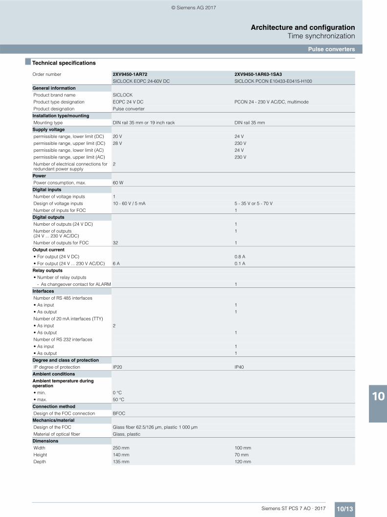
10/13Siemens ST PCS 7 AO · 2017
10
Architecture and configurationTime synchronization
Pulse converters
■ Technical specifications
Order number 2XV9450-1AR72 2XV9450-1AR63-1SA3
SICLOCK EOPC 24-60V DC SICLOCK PCON E10433-E0415-H100
General information
Product brand name SICLOCK
Product type designation EOPC 24 V DC PCON 24 - 230 V AC/DC, multimode
Product designation Pulse converter
Installation type/mounting
Mounting type DIN rail 35 mm or 19 inch rack DIN rail 35 mm
Supply voltage
permissible range, lower limit (DC) 20 V 24 V
permissible range, upper limit (DC) 28 V 230 V
permissible range, lower limit (AC) 24 V
permissible range, upper limit (AC) 230 V
Number of electrical connections for redundant power supply
2
Power
Power consumption, max. 60 W
Digital inputs
Number of voltage inputs 1
Design of voltage inputs 10 - 60 V / 5 mA 5 - 35 V or 5 - 70 V
Number of inputs for FOC 1
Digital outputs
Number of outputs (24 V DC) 1
Number of outputs (24 V ... 230 V AC/DC)
1
Number of outputs for FOC 32 1
Output current
• For output (24 V DC) 0.8 A
• For output (24 V ... 230 V AC/DC) 6 A 0.1 A
Relay outputs
• Number of relay outputs
- As changeover contact for ALARM 1
Interfaces
Number of RS 485 interfaces
• As input 1
• As output 1
Number of 20 mA interfaces (TTY)
• As input 2
• As output 1
Number of RS 232 interfaces
• As input 1
• As output 1
Degree and class of protection
IP degree of protection IP20 IP40
Ambient conditions
Ambient temperature during operation
• min. 0 °C
• max. 50 °C
Connection method
Design of the FOC connection BFOC
Mechanics/material
Design of the FOC Glass fiber 62.5/126 μm, plastic 1 000 μm
Material of optical fiber Glass, plastic
Dimensions
Width 250 mm 100 mm
Height 140 mm 70 mm
Depth 135 mm 120 mm
© Siemens AG 2017

10/14 Siemens ST PCS 7 AO · 2017
10
Architecture and configurationTime synchronization
Pulse converters
■ Ordering data Article No. ■ More information
For further product details, refer to the • "SICLOCK PCON" operating instructions• http://support.automation.siemens.com/WW/view/en/73996703• "SICLOCK EOPC Electrical Optical Pulse Converters"operating
instructionshttp://support.automation.siemens.com/WW/view/en/73996778
Pulse converters Article No.
SICLOCK PCON 2XV9450-1AR63-1SA3
Single-channel, electrical-optical pulse converter for industrial appli-cations, 820 nm, 24 ... 230 V AC/DC, with multimode fiber optic connection
SICLOCK EOPC 2XV9450-1AR72
Electrical-optical pulse converter for industrial applications with 32 fiber-optic cable outlets for trans-parent operation and pulse mode, 24 ... 110 V DC
© Siemens AG 2017

10/15Siemens ST PCS 7 AO · 2017
10
Architecture and configurationTime synchronization
Accessories
■ Overview
Software
For less complex applications, the wireless receivers can even be operated without central plant clocks.
Two software packages are available for such applications to process the time information on Windows computers or in a SIMATIC PLC.• 2XV9450-1AR28: SICLOCK DCF77 receiving service software
for Windows XP, Windows Vista, Windows 7, Windows Server 2003/2008/2008 R2
Lightning protection
The 2XV9450-1AR83 lightning protection element is integrated by default into the connecting cable downstream of the wireless receiver and protects the components connected to it against overvoltage caused by lightning strikes.
Mounting hardware
For easy installation in 19" rack units, a 2XV9450-2AR81 mount-ing frame for two SICLOCK TC100 and/or SICLOCK TC400 central plant clocks each is available.
■ Ordering data Article No.
■ Technical specifications
Article No.
Accessories
Software• Receiving service software for
Windows2XV9450-1AR28
Lightning protection for antenna cable
2XV9450-1AR83
Lightning protection for TTY connection cable for SICLOCK GPS1000 or SICLOCK DCFRS wireless receivers
Mounting frame for SICLOCK TC100 and SICLOCK TC400 central plant clocks
2XV9450-2AR81
Order number 2XV9450-2AR81 2XV9450-1AR28 2XV9450-1AR83
SICLOCK TC400 19" Materialsatz SICLOCK TREIBER DCF77 FUER WINDOWS
SICLOCK GPS1000 Protection
General information
Product brand name SICLOCK
Product designation 19 inch frame for SICLOCK TC400 / TC100
DCF77 receiver software for Windows Lightning protection for GPS1000 or DCFRS radio clock
Installation type/mounting
19-inch installation Yes
Number of modular height units 3
Time of day
Signal type
• At the input DCF77
• At the output DCF77
Digital inputs
Number of digital inputs 1
Digital outputs
Number of digital outputs 1
Operating systems
Required operating system Microsoft Windows XP, Windows Vista, Windows 7, Windows Server 2003, Windows Server 2008/2008 R2
© Siemens AG 2017

10/16 Siemens ST PCS 7 AO · 2017
10
Architecture and configurationTime synchronization
Bundles
■ Overview
The SICLOCK TC100 and SICLOCK TC400 central plant clocks can be operated with the SICLOCK GPS1000 or SICLOCK DCFRS wireless receivers.With the bundles you order the complete unit comprising:the central plant clock, the antennas/wireless receivers and the accessories required.
■ Ordering data Article No.
Bundles Article No.
SICLOCK Bundle TC400 2XV9450-2AR10-0AA0
Complete solution, e.g. for use in PCS 7,package comprises• SICLOCK TC400
• SICLOCK GPS2000 antenna with 2.5 m connecting cable, mounted, extendable to 1 000 m
• Antenna frame
• Distribution socket
• Lightning protection
SICLOCK Bundle TC100 2XV9450-2AR50-0AA0
Complete solution, e.g. for use in PCS 7,package comprises• SICLOCK TC100
• SICLOCK GPS2000 antenna with 2.5 m connecting cable, mounted, extendable to 1 000 m
• Antenna frame
• Distribution socket
• Lightning protection
© Siemens AG 2017

Siemens ST PCS 7 AO · 2017
111012 Conditions of sale and delivery
Appendix
© Siemens AG 2017

Appendix
Conditions of sale and delivery
11/2 Siemens ST PCS 7 AO · 2017
11
■ 1. General Provisions
By using this catalog you can acquire hardware and software products described therein from Siemens AG subject to the following Terms and Conditions of Sale and Delivery (hereinafter referred to as "T&C"). Please note that the scope, the quality and the conditions for supplies and services, including software products, by any Siemens entity having a registered office outside Germany, shall be subject exclusively to the General Terms and Conditions of the respective Siemens entity. The following T&C apply exclusively for orders placed with Siemens Aktiengesellschaft, Germany.
1.1 For customers with a seat or registered office in GermanyFor customers with a seat or registered office in Germany, the following applies subordinate to the T&C:• the "General Terms of Payment"1) and,• for software products, the "General License Conditions for
Software Products for Automation and Drives for Customers with a Seat or Registered Office in Germany"1) and,
• for other supplies and services, the "General Conditions for the Supply of Products and Services of the Electrical and Electronics Industry"1).
1.2 For customers with a seat or registered office outside GermanyFor customers with a seat or registered office outside Germany, the following applies subordinate to the T&C:• the "General Terms of Payment"1) and,• for software products, the "General License Conditions for
Software Products for Automation and Drives for Customers with a Seat or Registered Office outside of Germany"1) and
• for other supplies and/or services, the "General Conditions for Supplies of Siemens Industry for Customers with a Seat or Registered Office outside of Germany"1).
■ 2. Prices
The prices are in € (Euro) ex point of delivery, exclusive of packaging.The sales tax (value added tax) is not included in the prices. It shall be charged separately at the respective rate according to the applicable statutory legal regulations.Prices are subject to change without prior notice. We will charget the prices valid at the time of delivery.To compensate for variations in the price of raw materials (e.g. silver, copper, aluminum, lead, gold, dysprosium and neodym), surcharges are calculated on a daily basis using the so-called metal factor for products containing these raw materials. A surcharge for the respective raw material is calculated as a supplement to the price of a product if the basic official price of the raw material in question is exceeded.The metal factor of a product indicates the basic official price (for those raw materials concerned) as of which the surcharges on the price of the product are applied, and with what method of calculation. An exact explanation of the metal factor can be downloaded at:www.siemens.com/automation/salesmaterial-as/catalog/en/terms_of_trade_en.pdfTo calculate the surcharge (except in the cases of dysprosium and neodym), the official price from the day prior to that on which the order was received or the release order was effected is used.To calculate the surcharge applicable to dysprosium and neodym ("rare earths"), the corresponding three-month basic average price in the quarter prior to that in which the order was received or the release order was effected is used with a one-month buffer (details on the calculation can be found in the explanation of the metal factor).
■ 3. Additional Terms and Conditions
The dimensions are in mm. In Germany, according to the German law on units in measuring technology, data in inches apply only to devices for export.Illustrations are not binding.Insofar as there are no remarks on the individual pages of this catalog - especially with regard to data, dimensions and weights given - these are subject to change without prior notice.
■ 4. Export regulations
We shall not be obligated to fulfill any agreement if such fulfillment is prevented by any impediments arising out of national or international foreign trade or customs requirements or any embargoes and/or other sanctions.Export of goods listed in this catalog may be subject to licensing requirements. We will indicate in the delivery details whether licenses are required under German, European and US export lists. Goods labeled with "AL" not equal to "N" are subject to European or German export authorization when being exported out of the EU. Goods labeled with "ECCN" not equal to "N" are subject to US re-export authorization. The export indications can be viewed in advance in the description of the respective goods on the Industry Mall, our online catalog system. Only the export labels "AL" and "ECCN" indicated on order confirmations, delivery notes and invoices are authoritative.Even without a label, or with label "AL:N" or "ECCN:N", authori-zation may be required i .a. due to the final disposition and intended use of goods.If you transfer goods (hardware and/or software and/or technology as well as corresponding documentation, regardless of the mode of provision) delivered by us or works and services (including all kinds of technical support) performed by us to a third party worldwide, you must comply with all applicable national and international (re-)export control regulations.If required for the purpose of conducting export control checks, you (upon request by us) shall promptly provide us with all infor-mation pertaining to the particular end customer, final dispo-sition and intended use of goods delivered by us respectively works and services provided by us, as well as to any export control restrictions existing in this relation.The products listed in this catalog may be subject to European/German and/or US export regulations. Any export requiring approval is therefore subject to authorization by the relevant authorities.Errors excepted and subject to change without prior notice.
1) The text of the Terms and Conditions of Siemens AG can be downloaded atwww.siemens.com/automation/salesmaterial-as/catalog/en/terms_of_trade_en.pdf
© Siemens AG 2017

CatalogsDigital Factory, Process Industries and Drives and Energy Management
Further information can be obtained from our branch offices listed at www.siemens.com/automation-contact
Interactive Catalog on DVD CatalogProducts for Automation and Drives CA 01
Building ControlGAMMA Building Control ET G1
Drive SystemsSINAMICS G130 Drive Converter Chassis Units SINAMICS G150 Drive Converter Cabinet Units
D 11
SINAMICS GM150, SINAMICS SM150 Medium-Voltage Converters
D 12
SINAMICS PERFECT HARMONY GH180 Medium-Voltage Air-Cooled Drives (Germany Edition)
D 15.1
SINAMICS G180 Converters – Compact Units, Cabinet Systems, Cabinet Units Air-Cooled and Liquid-Cooled
D 18.1
SINAMICS S120 Chassis Format Units and Cabinet Modules SINAMICS S150 Converter Cabinet Units
D 21.3
SINAMICS S120 and SIMOTICS D 21.4SINAMICS DCM DC Converter, Control Module D 23.1SINAMICS DCM Cabinet D 23.2SINAMICS Inverters for Single-Axis Drives and SIMOTICS Motors
D 31
Digital: SINAMICS G120P and SINAMICS G120P Cabinet pump, fan, compressor converters
D 35
LOHER VARIO High Voltage Motors Flameproof, Type Series 1PS4, 1PS5, 1MV4 and 1MV5Frame Size 355 to 1000, Power Range 80 to 7100 kW
D 83.2
Three-Phase Induction Motors SIMOTICS HV, SIMOTICS TN
D 84.1
High Voltage Three-phase Induction Motors SIMOTICS HV Series A-compact PLUS
D 84.9
Three-Phase Induction Motors SIMOTICS HV, Series H-compact
D 86.1
Synchronous Motors with Permanent-Magnet Technology, HT-direct
D 86.2
DC Motors DA 12SIMOREG DC MASTER 6RA70 Digital Chassis Converters
DA 21.1
SIMOREG K 6RA22 Analog Chassis Converters DA 21.2Digital: SIMOREG DC MASTER 6RM70 Digital
Converter Cabinet UnitsDA 22
SIMOVERT PM Modular Converter Systems DA 45SIEMOSYN Motors DA 48MICROMASTER 420/430/440 Inverters DA 51.2MICROMASTER 411/COMBIMASTER 411 DA 51.3
Low-Voltage Three-Phase-MotorsSIMOTOCS S-1FG1 Servo geared motors D 41SIMOTICS Low-Voltage Motors D 81.1SIMOTICS FD Low-Voltage Motors D 81.8LOHER Low-Voltage Motors D 83.1MOTOX Geared Motors D 87.1SIMOGEAR Geared Motors MD 50.1SIMOGEAR Gearboxes with adapter MD 50.11
Mechanical Driving MachinesFLENDER Standard Couplings MD 10.1FLENDER High Performance Couplings MD 10.2FLENDER Backlash-free Couplings MD 10.3FLENDER SIP Standard industrial planetary gear units MD 31.1
Process Instrumentation and AnalyticsDigital: Field Instruments for Process Automation FI 01Digital: Display Recorders SIREC D MP 20Digital: SIPART Controllers and Software MP 31Products for Weighing Technology WT 10Process Analytical Instruments AP 01Digital: Process Analytics, Components for Continuous
Emission MonitoringAP 11
Low-Voltage Power Distribution and Electrical Installation Technology
Catalog
SENTRON · SIVACON · ALPHA Protection, Switching, Measuring and Monitoring Devices, Switchboards and Distribution Systems
LV 10
Standards-Compliant Components for Photovoltaic Plants
LV 11
Electrical Components for the Railway Industry LV 12TÜV-certified Power Monitoring System LV 14Components for Industrial Control Panels according to UL Standards
LV 16
3WT Air Circuit Breakers up to 4000 A LV 353VT Molded Case Circuit Breakers up to 1600 A LV 36Digital: SIVACON System Cubicles, System Lighting
and System Air-ConditioningLV 50
Digital: ALPHA Distribution Systems LV 51ALPHA FIX Terminal Blocks LV 52SIVACON S4 Power Distribution Boards LV 56SIVACON 8PS Busbar Trunking Systems LV 70Digital: DELTA Switches and Socket Outlets ET D1
Motion ControlSINUMERIK 840Equipment for Machine Tools
NC 62
SINUMERIK 808 Equipment for Machine Tools
NC 81.1
SINUMERIK 828 Equipment for Machine Tools
NC 82
SIMOTIONEquipment for Production Machines
PM 21
Digital: Drive and Control Components for Cranes CR 1
Power SupplySITOP Power supply KT 10.1
Safety IntegratedSafety Technology for Factory Automation SI 10
SIMATIC HMI / PC-based AutomationHuman Machine Interface Systems/PC-based Automation
ST 80/ ST PC
SIMATIC IdentIndustrial Identification Systems ID 10
SIMATIC Industrial Automation SystemsProducts for Totally Integrated Automation ST 70SIMATIC PCS 7 Process Control System System components
ST PCS 7
SIMATIC PCS 7 Process Control System Technology components
ST PCS 7 T
Add-ons for the SIMATIC PCS 7 Process Control System
ST PCS 7 AO
SIMATIC NETIndustrial Communication IK PI
SIRIUS Industrial Controls SIRIUS Industrial Controls IC 10
Digital: These catalogs are only available as a PDF.
Information and Download Center
Digital versions of the catalogs are available on the Internet at:www.siemens.com/industry/infocenter There you’ll find additional catalogs in other languages.
Please note the section “Downloading catalogs” on page “Online services” in the appendix of this catalog.
© Siemens AG 2017

Get more informationComprehensive information concerning the SIMATIC PCS 7 process control system:www.siemens.com/simatic-pcs7
Siemens AGProcess Industries and DrivesAutomation and Engineering76181 KarlsruheGermany
© Siemens AG 2017Subject to change without prior noticePDF (E86060-K4678-A121-B3-7600)KG 0417 108 EnProduced in Germany
The information provided in this catalog contains descriptions or characteristics of performance which in case of actual use do not always apply as described or which may change as a result of further development of the products. An obligation to provide the respective characteristics shall only exist if expressly agreed in the terms of contract. Availability and technical specifications are subject to change without notice.
All product designations may be trademarks or product names of Siemens AG or supplier companies whose use by third parties for their own purposes could violate the rights of the owners.
Security informationSiemens provides products and solutions with industrial security functions that support the secure operation of plants, systems, machines and networks.
In order to protect plants, systems, machines and networks against cyber threats, it is necessary to implement – and continuously maintain – a holistic, state-of-the-art indus-trial security concept. Siemens’ products and solutions only form one element of such a concept.
Customer is responsible to prevent unauthorized access to its plants, systems, machines and networks. Systems, machines and components should only be connected to the enterprise network or the internet if and to the extent necessary and with appropriate security measures (e.g. use of firewalls and network segmentation) in place.
Additionally, Siemens’ guidance on appropriate security measures should be taken into account. For more informa-tion about industrial security, please visit www.siemens.com/industrialsecurity.
Siemens’ products and solutions undergo continuous development to make them more secure. Siemens strongly recommends to apply product updates as soon as available and to always use the latest product versions. Use of product versions that are no longer supported, and failure to apply latest updates may increase customer’s exposure to cyber threats.
To stay informed about product updates, subscribe to the Siemens Industrial Security RSS Feed under www.siemens.com/industrialsecurity.
© Siemens AG 2017