adapter placement reference for aix - ibm...
TRANSCRIPT

RS/6000 and Eserver pSeries
Adapter Placement Reference for AIX
SA38-0538-24
ERserver
���


RS/6000 and Eserver pSeries
Adapter Placement Reference for AIX
SA38-0538-24
ERserver
���

Twenty-Fifth Edition (August 2004)
Before using this information and the products it supports, read the information in Appendix A, “Notices,” on page
231.
A reader’s comment form is provided at the back of this publication. If the form has been removed, address
comments to Information Development, Department H6DS-905-6C006, 11501 Burnet Road, Austin, Texas
78758-3493. To send comments electronically, use this commercial internet address: [email protected]. Any
information that you supply may be used without incurring any obligation to you.
© International Business Machines Corporation 1996, 2003, 2004. All rights reserved.
Note to U.S. Government Users Restricted Rights--Use, duplication or disclosure restricted by GSA ADP Schedule
Contract with IBM Corp.

Contents
About This Book . . . . . . . . . . . . . . . . . . . . . . . . . . . . . . . . vii
ISO 9000 . . . . . . . . . . . . . . . . . . . . . . . . . . . . . . . . . . . vii
Highlighting . . . . . . . . . . . . . . . . . . . . . . . . . . . . . . . . . . . vii
Accessing Information . . . . . . . . . . . . . . . . . . . . . . . . . . . . . . . vii
References to AIX Operating System . . . . . . . . . . . . . . . . . . . . . . . . . vii
Related Publications . . . . . . . . . . . . . . . . . . . . . . . . . . . . . . . vii
Trademarks . . . . . . . . . . . . . . . . . . . . . . . . . . . . . . . . . . viii
Chapter 1. Peripheral Component Interconnect Overview . . . . . . . . . . . . . . . . . 1
System Performance . . . . . . . . . . . . . . . . . . . . . . . . . . . . . . . . 1
PCI Slots . . . . . . . . . . . . . . . . . . . . . . . . . . . . . . . . . . . . 1
Secondary PCI Bus . . . . . . . . . . . . . . . . . . . . . . . . . . . . . . . 2
Multiple Primary PCI Buses . . . . . . . . . . . . . . . . . . . . . . . . . . . . 2
Hot Pluggable PCI Slots . . . . . . . . . . . . . . . . . . . . . . . . . . . . . 2
Integrated Adapters . . . . . . . . . . . . . . . . . . . . . . . . . . . . . . . . 3
32-Bit Versus 64-Bit PCI Slots . . . . . . . . . . . . . . . . . . . . . . . . . . . . 3
33 MHz versus 50/66 MHz 64-Bit PCI Slots . . . . . . . . . . . . . . . . . . . . . . . 3
Connectivity versus Performance Overview . . . . . . . . . . . . . . . . . . . . . . . 4
Other Restrictions . . . . . . . . . . . . . . . . . . . . . . . . . . . . . . . . . 4
Chapter 2. Models S70, S7A, and S80 . . . . . . . . . . . . . . . . . . . . . . . . 5
Performance Limits . . . . . . . . . . . . . . . . . . . . . . . . . . . . . . . . 12
Models S70, S7A, and S80 Configuration Details . . . . . . . . . . . . . . . . . . . . . 13
Chapter 3. pSeries 680 Model S85 . . . . . . . . . . . . . . . . . . . . . . . . . 15
Performance Limits . . . . . . . . . . . . . . . . . . . . . . . . . . . . . . . . 22
pSeries 680 Model S85 Configuration Details . . . . . . . . . . . . . . . . . . . . . . 24
Chapter 4. 7024 Models E20 and E30 . . . . . . . . . . . . . . . . . . . . . . . . 25
7024 Models E20 and E30 Adapter Placement Guide . . . . . . . . . . . . . . . . . . . 25
Chapter 5. 7025 Model 6F0, 7025 Model 6F1 and 7025 Model F80 . . . . . . . . . . . . . 29
7025 Model 6F0, 7025 Model 6F1 and 7025 Model F80 . . . . . . . . . . . . . . . . . . 30
Chapter 6. 7025 Model F30 . . . . . . . . . . . . . . . . . . . . . . . . . . . . 35
7025 Model F30 Adapter Placement Guide . . . . . . . . . . . . . . . . . . . . . . . 35
Chapter 7. 7025 Model F40 . . . . . . . . . . . . . . . . . . . . . . . . . . . . 39
7025 Model F40 Adapter Placement Guide . . . . . . . . . . . . . . . . . . . . . . . 39
7025 Model F40 Multiple Graphics Adapter Placement Guide . . . . . . . . . . . . . . . . 43
Chapter 8. 7025 Model F50 . . . . . . . . . . . . . . . . . . . . . . . . . . . . 45
7025 Model F50 Adapter Placement Guide . . . . . . . . . . . . . . . . . . . . . . . 45
Chapter 9. 7026 Model 6M1 and 7026 Model M80 . . . . . . . . . . . . . . . . . . . . 53
7026 Model 6M1 and 7026 Model M80Adapter Placement Guide . . . . . . . . . . . . . . . 54
Chapter 10. 7026 Model B80 . . . . . . . . . . . . . . . . . . . . . . . . . . . . 59
7026 Model B80 Adapter Placement Guide . . . . . . . . . . . . . . . . . . . . . . . 59
Chapter 11. 7026 Model H10 . . . . . . . . . . . . . . . . . . . . . . . . . . . . 63
7026 Model H10 Adapter Placement Guide . . . . . . . . . . . . . . . . . . . . . . . 63
iii

Chapter 12. 7026 Model H50 . . . . . . . . . . . . . . . . . . . . . . . . . . . . 67
7026 Model H50 Adapter Placement Guide . . . . . . . . . . . . . . . . . . . . . . . 67
Chapter 13. 7026 Model H70 . . . . . . . . . . . . . . . . . . . . . . . . . . . . 73
7026 Model H70 Adapter Placement Guide . . . . . . . . . . . . . . . . . . . . . . . 73
Chapter 14. 7026 Model 6H0, 7026 Model 6H1, and 7026 Model H80 . . . . . . . . . . . . 81
7026 Model 6H0, 7026 Model 6H1, and 7026 Model H80Adapter Placement Guide . . . . . . . . 82
Chapter 15. 7028 Models 6C1 and 6E1 . . . . . . . . . . . . . . . . . . . . . . . . 89
7028 Models 6C1 and 6E1 Adapter Placement Guide . . . . . . . . . . . . . . . . . . . 90
Chapter 16. 7028 Models 6C4 and 6E4 (Eserver pSeries 630) . . . . . . . . . . . . . . 93
Logical Partition (LPAR) Considerations . . . . . . . . . . . . . . . . . . . . . . . . 93
7028 Models 6C4 and 6E4 (Eserver pSeries 630) Adapter Placement Guide (4-Slot PCI Riser) . . . 94
7028 Models 6C4 and 6E4 (Eserver pSeries 630) Adapter Placement Guide (6-Slot PCI Riser) . . . 98
Chapter 17. 7029 Models 6C3 and 6E3 (Eserver pSeries 615) . . . . . . . . . . . . . . 103
Logical Partition (LPAR) Considerations . . . . . . . . . . . . . . . . . . . . . . . . 103
7029 Models 6C3 and 6E3 (Eserver pSeries 615) Adapter Placement Guide . . . . . . . . . 104
Chapter 18. 7038 Model 6M2 (Eserver pSeries 650) . . . . . . . . . . . . . . . . . . 109
Logical Partition (LPAR) Considerations . . . . . . . . . . . . . . . . . . . . . . . . 109
7038 Model 6M2 (Eserver pSeries 650) Adapter Placement Guide . . . . . . . . . . . . . 110
Chapter 19. 7039 Model 651 (Eserver pSeries 655) . . . . . . . . . . . . . . . . . . 113
Logical Partition (LPAR) Considerations . . . . . . . . . . . . . . . . . . . . . . . . 113
7039 Model 651 (Eserver pSeries 655) Adapter Placement Guide . . . . . . . . . . . . . 113
Chapter 20. 7040 Model 61D (Eserver pSeries 670) . . . . . . . . . . . . . . . . . . 129
Logical Partition (LPAR) Considerations . . . . . . . . . . . . . . . . . . . . . . . . 131
7040 Model 61D (Eserver pSeries 670) Adapter Placement Guide . . . . . . . . . . . . . 131
Chapter 21. 7040 Model 61D (Eserver pSeries 690) . . . . . . . . . . . . . . . . . . 143
Logical Partition (LPAR) Considerations . . . . . . . . . . . . . . . . . . . . . . . . 145
7040 Model 61D (Eserver pSeries 690) Adapter Placement Guide . . . . . . . . . . . . . 145
Chapter 22. 7043 Model 140 . . . . . . . . . . . . . . . . . . . . . . . . . . . 157
7043 Model 140 Adapter Placement Guide . . . . . . . . . . . . . . . . . . . . . . 157
7043 Model 140 Multiple Graphics Adapter Placement Guide . . . . . . . . . . . . . . . . 162
Chapter 23. 7043 Model 150 . . . . . . . . . . . . . . . . . . . . . . . . . . . 165
7043 Model 150 Adapter Placement Guide . . . . . . . . . . . . . . . . . . . . . . 165
7043 Model 150 Multiple Graphics Adapter Placement Guide . . . . . . . . . . . . . . . . 170
Chapter 24. 7043 Model 240 . . . . . . . . . . . . . . . . . . . . . . . . . . . 173
7043 Model 240 Adapter Placement Guide . . . . . . . . . . . . . . . . . . . . . . 173
7043 Model 240 Multiple Graphics Adapter Placement Guide . . . . . . . . . . . . . . . . 176
Chapter 25. 7043 Model 260 . . . . . . . . . . . . . . . . . . . . . . . . . . . 179
7043 Model 260 Adapter Placement Guide . . . . . . . . . . . . . . . . . . . . . . 179
7043 Model 260 Multiple Graphics Adapter Placement Guide . . . . . . . . . . . . . . . . 183
Chapter 26. 7044 Model 170 . . . . . . . . . . . . . . . . . . . . . . . . . . . 185
7044 Model 170 Adapter Placement Guide . . . . . . . . . . . . . . . . . . . . . . 186
7044 Model 170 Multiple Graphics Adapter Placement Guide . . . . . . . . . . . . . . . . 191
iv Adapter Placement Reference for AIX

Chapter 27. 7044 Model 270 . . . . . . . . . . . . . . . . . . . . . . . . . . . 193
7044 Model 270 Adapter Placement Guide . . . . . . . . . . . . . . . . . . . . . . 193
7044 Model 270 Multiple Graphics Adapter Placement Guide . . . . . . . . . . . . . . . . 198
Chapter 28. 7046 Model B50 . . . . . . . . . . . . . . . . . . . . . . . . . . . 199
7046 Model B50 Adapter Placement Guide . . . . . . . . . . . . . . . . . . . . . . 200
Chapter 29. 7248 Model 100, 120, or 132 . . . . . . . . . . . . . . . . . . . . . . 203
7248 Model 100, 120, or 132 Adapter Placement Guide . . . . . . . . . . . . . . . . . . 204
7248 Model 100, 120, or 132 Multiple Graphics Adapter Placement Guide . . . . . . . . . . . 205
Chapter 30. 7311 Model D10 . . . . . . . . . . . . . . . . . . . . . . . . . . . 207
Logical Partition (LPAR) Considerations . . . . . . . . . . . . . . . . . . . . . . . . 207
7311 Model D10 Adapter Placement Guide . . . . . . . . . . . . . . . . . . . . . . 208
Chapter 31. 7311 Model D20 . . . . . . . . . . . . . . . . . . . . . . . . . . . 211
Logical Partition (LPAR) Considerations . . . . . . . . . . . . . . . . . . . . . . . . 211
7311 Model D20 Adapter Placement Guide . . . . . . . . . . . . . . . . . . . . . . 212
Chapter 32. 9076 RS/6000 SP Systems . . . . . . . . . . . . . . . . . . . . . . . 215
Chapter 33. 9112 Model 265 . . . . . . . . . . . . . . . . . . . . . . . . . . . 217
9112 Model 265 Adapter Placement Guide . . . . . . . . . . . . . . . . . . . . . . . 218
Chapter 34. 9114 Model 275 . . . . . . . . . . . . . . . . . . . . . . . . . . . 221
9114 Model 275 Adapter Placement Guide . . . . . . . . . . . . . . . . . . . . . . . 221
Chapter 35. Digital Trunk PCI Adapter Placement Considerations . . . . . . . . . . . . . 225
Chapter 36. FC 2854: POWER GXT500P (Type 1-I) and FC 2855: POWER GXT550P (Type 1-J)
Support Configurations . . . . . . . . . . . . . . . . . . . . . . . . . . . . 227
Chapter 37. FC 2853: POWER GXT800P (Type 1-K) Support Configurations . . . . . . . . . 229
Appendix A. Notices . . . . . . . . . . . . . . . . . . . . . . . . . . . . . . 231
Appendix B. High-Performance Adapters . . . . . . . . . . . . . . . . . . . . . . 233
Contents v

vi Adapter Placement Reference for AIX

About This Book
This book outlines system-specific PCI adapter slot placement and adapter support configurations. Not all
of the adapters supported in stated maximum configurations run at per adapter maximum performance.
This book identifies Peripheral Component Interconnect (PCI) protocols with a ’P’ in document figures and
tables. The book identifies International Standard Architecture (ISA) and Extended International Standard
Architecture (EISA) with an ’I’ or with an ’E,’ respectively, in figures and tables.
ISO 9000
ISO 9000 registered quality systems were used in the development and manufacturing of this product.
Highlighting
The following highlighting conventions are used in this book:
Bold Identifies commands, subroutines, keywords, files, structures, directories, and other items
whose names are predefined by the system. Also identifies graphical objects such as buttons,
labels, and icons that the user selects.
Italics Identifies parameters whose actual names or values are to be supplied by the user.
Monospace Identifies examples of specific data values, examples of text similar to what you might see
displayed, examples of portions of program code similar to what you might write as a
programmer, messages from the system, or information you should actually type.
Accessing Information
IBM Eserver pSeries hardware publications are available online. To access the online hardware
publications, see the IBM Eserver pSeries and AIX Information Center at
http://publib16.boulder.ibm.com/pseries/index.htm. Click hardware documentation
Documentation for the AIX operating system is available at the IBM Eserver pSeries and AIX Information
Center at http://publib16.boulder.ibm.com/pseries/index.htm. Click AIX documentation. The AIX
Documentation CD contains the base set of publications for the operating system, including
system-management and end-user documentation.
References to AIX Operating System
This document may contain references to the AIX operating system. If you are using another operating
system, consult the appropriate documentation for that operating system.
This document may describe hardware features and functions. While the hardware supports them, the
realization of these features and functions depends upon support from the operating system. AIX provides
this support. If you are using another operating system, consult the appropriate documentation for that
operating system regarding support for those features and functions.
Related Publications
Use this book with your system unit documentation and with your adapter’s installation and user’s guide to
accurately place one or more adapters in your system unit.
Adapters, Devices and Cable Information for Multiple Bus Systems, (SA38-0516) provides specific
technical information about adapters. Also use the publication to identify an adapter.
vii

The RS/6000 SP Planning Volume 1, Hardware and Physical Environment (GA22-7280), contains adapter
slot restriction information for SP nodes.
Trademarks
The following terms are trademarks of the International Business Machines Corporation in the United
States, other countries, or both:
v AIX
v IBM ARTIC960
v ESCON
v PowerPC
v Eserver
v pSeries
v RS/6000
v SP
v TURBOWAYS
Microsoft and Windows NT are trademarks of Microsoft Corporation in the United States, other countries,
or both.
Other company, product, and service names may be trademarks or service marks of others.
viii Adapter Placement Reference for AIX

Chapter 1. Peripheral Component Interconnect Overview
This chapter presents a brief overview of some factors and issues related to Peripheral Component
Interconnect (PCI) bus adapter placement. The user can gain a better understanding of system
configurations, adapter placement, and performance issues by using the reference. Each of the following
chapters provides system-specific slot placement information.
You can install PCI adapters with the power on in some systems. These adapters are referred to as
hot-pluggable PCI adapters. Do not hot-plug any PCI adapter supporting the system’s boot device or
system console.
Refer to your system unit documentation to determine if your system unit supports hot-plugging adapters.
If an adapter is listed as a Type *, this adapter has not been assigned an adapter type.
System Performance
This book provides performance information related to PCI adapter placement. Understand that
maximizing system performance is relative to software and hardware. Information in this book may change
as new products are announced.
PCI Slots
Each PCI bus has a limit on the number of adapters it can support. Typically, this limit can range from two
adapters to six adapters per bus. To overcome this limit, the system design can implement multiple PCI
buses. You can use two different methods to add PCI buses to your system. These two methods are:
v Adding secondary PCI buses off the primary PCI bus
v Implementing multiple primary buses
1

Secondary PCI Bus
If you want to increase the number of PCI slots when designing a system, add a secondary PCI bus. A
PCI-to-PCI bridge chip can connect a secondary bus to a primary bus. The following illustration shows
how to use a primary PCI bus to increase the total number of PCI slots.
Secondary PCI Bus
Primary PCI Bus
I/O Interface
Slot 1
Slot S1
Slot 2
Slot S2
Slot n
Slot Sn
Bridge Chip
System Memory (RAM)
Because the slots on the secondary PCI bus must pass through the bridge chip, certain adapters on a
secondary PCI bus may experience lower performance.
Some of the systems in this book implement a secondary PCI bus. On these systems, place higher-speed
adapters on the primary bus to optimize performance.
Multiple Primary PCI Buses
To add more PCI slots in a different way, design the system with 2 or more primary PCI buses. This
design requires a more sophisticated I/O interface with the system memory. The following illustration
shows another method of increasing the number of PCI slots.
This design improves I/O performance over the secondary bus method because the I/O interface has
created multiple parallel paths into the system memory.
Hot Pluggable PCI Slots
Certain newer systems contain hot-plug enabled PCI slots. These systems dedicate a PCI bus to each
PCI slot, which allows the adapter to be removed or added without effecting other adapters. This
architecture uses one or more PCI primary buses that are bridged to multiple PCI secondary buses. Each
PCI secondary bus has a single PCI slot.
2 Adapter Placement Reference for AIX

PCI Secondary Buses, 1 per slot
PCI-Hot Plug Slots
I/O Interface
Slot 1 Slot 5Slot 2 Slot 6Slot 4Slot 3
System Memory (RAM)
PCI Controller
PCI Primary Buses
Integrated Adapters
The main processor board now integrates a number of devices, but they physically connect to one of the
PCI buses. For this reason, some of the buses may only have two or three slots available to install
adapters. Integrated PCI adapters include SCSI adapters and Ethernet adapters.
32-Bit Versus 64-Bit PCI Slots
Choosing between 32-bit and 64-bit slots influences slot placement and affects performance. Higher-speed
adapters use 64-bit slots because they can transfer 64 bits of data for each data transfer phase.
32-bit adapters can typically function in 64-bit PCI slots; however, 32-bit adapters still operate in 32-bit
mode and offer no performance advantage in a 64-bit slot. Likewise, most 64-bit adapters can operate in
32-bit PCI slots but the 64-bit adapter operates in 32-bit mode and reduces performance potential.
33 MHz versus 50/66 MHz 64-Bit PCI Slots
Some systems (for example, 7025 Model F50 and 7026 Model H50) offer 50 MHz capability on 64-bit
slots. Adapters capable of functioning at 50 MHz may take advantage of this. If you plug a 33 MHz
adapter into a 50 MHz 64-bit slot, the slot switches to 33 MHz and also switches the remaining slots on
this PCI bus to 33 MHz. For systems with hot plug PCI slots, adapters are not affected by the clock rate of
other adapters because each has its own PCI bus.
The following adapters run at 50 or 66 mhz when placed on a 50 or 66 mhz PCI bus, or 33 mhz when
placed on a 33 mhz PCI bus. If you place a 33 Mhz adapter on the same 50/66 Mhz PCI bus with any of
these adapters, the bus will run in 33 Mhz mode, which will reduce the performance potential of the
following 50/66 MHz adapters:
v FC 2969: Gigabit Ethernet Fibre, 1000BaseT, 64-bit, 3.3/5V (Type 9-U)
v FC 2851: POWER GXT250P (Type 1-M)
v FC 2852: POWER GXT255P (Type 1-N)
v FC 2841: POWER GXT300P (Type1-U)
v FC 2823: POWER GXT2000P (Type 1-S)
v FC 2825: POWER GXT3000P (Type 1-R)
v FC 2946: PCI TURBOWAYS 622 PCI MMF ATM, 64-bit, 3.3/5V (Type A-B)
v FC 6228: 2 Gigabit Fibre Channel Adapter for 32/64-bit, 3.3/5V PCI Bus (Type 4-W)
v FC 2975: Gigabit Ethernet (UTP) 1000BaseT, 64-bit, 3.3/5V (Type A-A)
v FC 6205: PCI Dual Channel Ultra2 SCSI (Type 4-R)
Chapter 1. Peripheral Component Interconnect Overview 3

v FC 2498: PCI 4-Channel Ultra3 SCSI RAID, 32/64-bit, 3.3/5V (Type 4-X)
Connectivity versus Performance Overview
You must consider some performance trade-offs when configuring your system. Installing the maximum
number of adapters might affect system performance. The following paragraphs provide an overview of
these considerations and how they are documented in later sections of this book.
Connectivity limits define how many specified adapters can be physically plugged into a system. This limit
defines how many adapters the software and hardware can support. Some adapters have specific
placement guidelines. Connectivity limits define the maximum number of adapters for connecting to
networks or disks. In many cases, a disk or network has a low duty-cycle and the system needs additional
adapters to retain the physical connection to all resources. In these cases, you should follow connectivity
limits.
This book also provides suggested performance limits, established to determine how many concurrently
running adapters can provide good performance. As you add adapters (with each adapter performing at
close to its rated speed), additional adapters continue to provide an incremental performance increase.
Once the system reaches its performance limit, adding more adapters does not provide an increase in I/O
throughput.
A number of factors can determine the performance limit. Bus speed, memory speed, adapter design, or
processor speed can influence performance. Quite often, the system processor’s speed may limit how
many adapters of a given type the system can support while maintaining maximum performance. Once a
system uses 90 percent of its system processor, adding more adapters only provides a minor throughput
increase.
Due to the wide variety of workloads, this book provides performance-limit guidelines only. The guidelines
are based on I/O streaming of large reads or writes to a disk or network. They are not based on small
I/Os, which are more transaction-rate limited. Small I/O workloads probably use more system processor
capacity and result in fewer supported adapters for maximum performance.
The book bases these guidelines on the maximum number of processors supported for multi-processor
systems. If your system runs less than the maximum number of processors supported, then typically you
must reduce the maximum number of adapters by the same ratio. For example, if a system with a
maximum of twelve processors can support twelve ATM adapters for maximum performance, then the
same system with eight processors can only support eight ATM adapters for maximum performance.
If your system uses disk and communication adapters concurrently, use a more conservative estimate of
the number of supported adapters.
If your configured system runs close to its performance limits, take extra care to ensure that your system
type or configuration provides the desired performance. In these cases, you may need to contact your
marketing support personnel for more detailed information.
Other Restrictions
You must install some adapters in specific PCI slots in various systems. Physical size limits, I/O address
considerations, thermal limitations, and other factors influence these specifications.
This book lists slot placement information for PCI adapters in system units that have specific restrictions or
guidelines. However, this book does not list all system-compatible PCI adapters.
4 Adapter Placement Reference for AIX

Chapter 2. Models S70, S7A, and S80
These systems are designed for service representatives to install adapters. Use this guide to determine if
there are specific slot requirements for adapters that your service representative may be installing.
I/O Drawer Rear View with 14 Slots and 4 PCI Buses
Note: Each drawer has four PCI buses per drawer: Slots 1-4 (PCI Bus 1), 5-8 (PCI Bus 0), 9-10 (PCI Bus
3), 11-14 (PCI Bus 2). Slots 1, 5, 9, 10 and 14 are 64-bit slots. Remaining slots are 32-bit. The
32-bit adapters also function in the 64-bit slots. Each bus is considered a primary bus. All slots are
33 MHz.
Some adapters must be placed in specific I/O drawer slots to function correctly and to achieve optimum
performance.
Many of the following notes refer to optimizing system performance. Read “System Performance” on page
1 for more performance-related information.
The following table shows the slot-plugging guidelines for Models S70, S7A, and S80 systems.
If two different adapters can be placed in the same slot, the highest priority adapter starts at the top of the
table. The list of slot numbers represent the order that the slots should be used in a drawer.
For complete system placement, the first slot for a group of adapters is selected in the first drawer, and
then the first slot is selected in the next drawer. After the first slot selection has been used for each
drawer, the second slot in the list is used. This also rotates through the available drawers. If a card has
already been placed in a slot, the slot is not available for future adapter placement.
If a table row lists more than one adapter, the adapters may be mixed, but the total number of adapters in
the combination cannot exceed the number stated in the Maximum column.
The primary drawer referenced in the following table is the I/O drawer that has a service processor card
installed in slot 8. Secondary drawers are additional I/O drawers that may be added to a Models S70,
S7A, and S80 configuration. Secondary drawers do not have a service processor installed.
Table 1. Models S70, S7A, and S80
Adapter Slot Usage S70 Max S7A Max S80 Max
FC 6326: Service Processor Primary drawer slot 8 1 per system 1 per system 1 per system
5

Table 1. Models S70, S7A, and S80 (continued)
Adapter Slot Usage S70 Max S7A Max S80 Max
FC 8396: SP System
Attachment, 32-bit, 5V, 2-slot
(Type 6-F)
FC 8397: SP System
Attachment, 64-bit, 3.3/5V,
2-slot
See Chapter 32, “9076
RS/6000 SP Systems,” on
page 215.
Primary drawer slot 10; slots 9 and 11
must be empty
1 per system 1 per system 1 per system
FC 6310: IBM ARTIC960
RxD Quad Digital Trunk PCI,
32-bit, 3.3/5V (Type 6-E)
Primary drawer - slots 1, 3, 4, 2
Secondary drawer - slots 1, 3, 4, 2
See Chapter 35, “Digital Trunk PCI
Adapter Placement Considerations,” on
page 225 and note 12 on page 11.
4 per system 4 per system 4 per system
FC 6311: IBM ARTIC960 RxF
PCI, 32-bit, 3.3/5V (Type
6-G)
Primary drawer slots 3, 2, 4
Secondary drawer slots - 3, 2, 4
See Chapter 35, “Digital Trunk PCI
Adapter Placement Considerations,” on
page 225 and note 12 on page 11.
Not Supported 3 per system
See Chapter 35,
“Digital Trunk PCI
Adapter
Placement
Considerations,”
on page 225.
Not Supported
FC 2751: S/390 ESCON
Channel, 32-bit, 5V, (Type
5-5)
Primary drawer slots 14, 10
Secondary drawer slots 14, 10
FC 2751: S/390 ESCON Channel, 32-bit,
5V, (Type 5-5) adapters can only be
installed in the primary I/O drawer and
the secondary I/O drawer that are cabled
in the same RIO loop.
See note 11 on page 11.
4 per system 4 per system 4 per system
FC 6208: PCI SCSI-2 Single
Ended Fast/Wide (Type 4-A)
Factory installed to support
internal media and SCSI
drives.
For information regarding
placement of additional,
non-factory installed 4-A
adapters, please reference
further ahead in this table.
Primary drawer - for media devices: slot
7; for SCSI devices: slot 13
Secondary drawer - for media devices:
slot 8 (as required); for SCSI devices:
slot 13 (as required).
Systems manufactured before October
23, 1998 may have this adapter installed
in slot 2 for supporting media devices,
and slot 9 for supporting SCSI devices.
2 per drawer Not Supported Not Supported
FC 6206: Single-Ended Ultra
SCSI Adapter, 32-bit, 5V
(Type 4-K)
Slot 7 is SCSI Media, slots
13 and 6 are SCSI drive.
For information regarding
placement of additional,
non-factory installed 4-K
adapters, please reference
further ahead in this table.
Primary drawer - slot 7, 13, 6
Secondary drawer - slot 13, 6 (As
required)
Not Supported 3 per drawer 3 per drawer
6 Adapter Placement Reference for AIX

Table 1. Models S70, S7A, and S80 (continued)
Adapter Slot Usage S70 Max S7A Max S80 Max
FC 6227: Gigabit Fibre
Channel PCI (Type 4-S)
See note 5 on page 11.
This adapter may already be
installed in the S80 system in
slots 4 and/or 9, which is
acceptable. However, to
optimize system
performance, place this
adapter into the drawer slots
listed.
Primary drawer - slots 14, 10, 1
Secondary drawer - slots 1, 5, 10, 14
4 per system 4
per I/O drawer
See note 16 on
page 11.
15 per system, 4
per I/O drawer
See note 16 on
page 11.
15 per system, 4
per I/O drawer
See note 16 on
page 11.
FC 6228: 2 Gigabit Fibre
Channel Adapter for
32/64-bit, 3.3/5V PCI Bus
(Type 4-W)
See note 15 on page 11.
This adapter may already be
installed in the S80 system in
slots 4 and/or 9, which is
acceptable. However, to
optimize system
performance, place this
adapter into the drawer slots
listed.
Primary drawer - slots 14, 10, 1
Secondary drawer - slots 1, 5, 10, 14
Not Supported 15 per system, 4
per I/O drawer
See note 16 on
page 11.
15 per system, 4
per I/O drawer
See note 16 on
page 11.
FC 2946: PCI TURBOWAYS
622 PCI MMF ATM, 64-bit,
3.3/5V (Type A-B)
Primary drawer - slots 10, 14, 1, 9
Secondary drawer - slots 1, 5, 9, 14, 10,
2, 6, 11, 3, 7, 12, 4, 8, 13
(See “Performance Limits” on page 12).
Not Supported 19 per system,
max of 4 in
primary and 5 in
secondary
drawers
19 per system,
max of 4 in
primary and 5 in
secondary
drawers
FC 2975: Gigabit Ethernet
(UTP) 1000BaseT, 64-bit,
3.3/5V (Type A-A)
This adapter may already be
installed in the S80 system in
slots 11 and/or 13, which is
not acceptable and severely
impacts system performance.
To optimize system
performance, place this
adapter into the drawer slots
listed.
Primary drawer - slots 10, 1, 9, 3, 4, 2
Secondary drawer - slots 1, 5, 10, 9, 3, 7
Not Supported 24 per system
See
“Performance
Limits” on page
12 and note 13
on page 11.
24 per system
See
“Performance
Limits” on page
12 and note 13
on page 11.
FC 2493: PCI SCSI-2
Fast/Wide RAID (Type 4-H)
Primary drawer - slots 10, 14, 1
Secondary drawer - slots 1, 5, 10, 14
12 Not Supported Not Supported
FC 6215: PCI SSA
Multi-Initiator/RAID EL (Type
4-N)
See notes 1 on page 10 and
2 on page 11.
Primary drawer - slots 3, 14, 10, 12, 1, 9See note 17 on page 11.
Secondary drawer - slots 1, 5, 10, 14, 3,
7, 12, 9See note 17 on page 11.
26 per system 26 per system 26 per system
FC 6225: Advanced SSA
SerialRAID (Type 4-P)
Primary drawer - slots 3, 14, 10, 12, 1, 9See note 17 on page 11.
Secondary drawer - slots 1, 5, 10, 14, 3,
7, 12, 9See note 17 on page 11.
26 per system 26 per system 26 per system
Chapter 2. Models S70, S7A, and S80 7

Table 1. Models S70, S7A, and S80 (continued)
Adapter Slot Usage S70 Max S7A Max S80 Max
FC 6230: Advanced
SerialRAID Plus, 32-bit,
3.3/5V (Type 4-P)
FC 6230+6231: 4 Port SSA
40 w/128MB DIMM
Primary drawer - slots 3, 14, 10, 12, 1, 9See note 17 on page 11.
Secondary drawer - slots 1, 5, 10, 14, 3,
7, 12, 9See note 17 on page 11.
26 per system 26 per system 26 per system
FC 6205: PCI Dual Channel
Ultra2 SCSI (Type 4-R)
Primary drawer - slots 3, 14, 10, 12, 1, 9
Secondary drawer - slots 1, 5, 10, 14, 3,
7, 12, 9
Not Supported 26 per system 26 per system, 11
per drawer
See note 10 on
page 11.
FC 6203: Dual-Channel
Ultra3 SCSI, 32/64-bit, 3.3/5V
(Type 4-Y)
Primary drawer - slots 3, 14, 10, 12, 1, 9
Secondary drawer - slots 1, 5, 10, 14, 3,
7, 12, 9
Not Supported Not Supported 26 per system, 11
per drawer
See note 10 on
page 11.
FC 2498: PCI 4-Channel
Ultra3 SCSI RAID, 32/64-bit,
3.3/5V (Type 4-X)
Primary drawer - slots 3, 14, 10, 12, 1
Secondary drawer - slots 1, 5, 10, 14, 3,
7, 12
Not Supported 15 per system Not Supported
FC 4961: 10/100 4-Port
Ethernet, 32/64-bit, 3.3/5V
(Type A-E)
See note 14 on page 11.
Primary drawer slots - 3, 10, 1, 9, 4, 2
Secondary drawer slots - 1, 5, 10, 3, 7, 9,
4
Not Supported 19 per system 19 per system
FC 2838: POWER GXT120P
(Type 1-P)
See note 3 on page 11.
Primary drawer - slots 1, 4 1 per system 1 per system 1 per system
FC 2830: POWER GXT130P
(Type 1-T)
See note 3 on page 11.
Primary drawer - slots 1, 4, 2, 3 1 per system 1 per system 1 per system
FC 2969: Gigabit Ethernet
Fibre, 1000BaseT, 64-bit,
3.3/5V (Type 9-U)
This adapter may already be
installed in the S80 system in
slots 11 and/or 13, which is
not acceptable and severely
impacts system performance.
To optimize system
performance, place this
adapter into the drawer slots
listed.
Primary drawer slots - 10, 1, 9, 3, 4, 2
Secondary drawer slots - 1, 5, 10, 9, 3, 7
8
See note 5 on
page 11.
8
See note 5 on
page 11.
24 per system
See note 5 on
page 11.
FC 2963: TURBOWAYS 155
PCI UTP ATM (Type 9-J)
FC 2988: TURBOWAYS 155
PCI MMF ATM (Type 9-F)
Primary drawer - slots 2, 4, 9, 11, 13, 3,
10, 12, 6, 1, 5, 7
Secondary drawer - slots 2, 4, 6, 8, 9, 11,
13, 3, 7, 10, 12, 14, 1, 5
See note 11 on page 11.
16 per system
See note 6 on
page 11.
16 per system
See note 6 on
page 11.
26 per system
11 per drawer
See note 6 on
page 11.
FC 4953: 64-bit/66MHz PCI
ATM 155 UTP, 3.3/5V (Type
A-C)
FC 4957: 64-bit/66MHz PCI
ATM 155 MMF, 3.3/5V (Type
A-D)
See note 8 on page 11.
Primary drawer - slots 10, 14, 1, 5, 9, 3,
12, 2, 11, 13, 6
Secondary drawer - slots 1, 5, 10, 14, 9,
10, 2, 6, 11, 3, 7, 12, 4, 8, 3
See note 11 on page 11
Not Supported Not Supported 26 per system
8 Adapter Placement Reference for AIX

Table 1. Models S70, S7A, and S80 (continued)
Adapter Slot Usage S70 Max S7A Max S80 Max
FC 2968: 10/100 Mbps
Ethernet Tx PCI (Type 9-P )
See note 8 on page 11.
Primary drawer - slots 2, 4, 9, 11, 13, 3,
10, 12, 6, 1, 5, 7
Secondary drawer - slots 2, 4, 6, 8, 9, 11,
13, 3, 7, 10, 12, 14, 1, 5
See note 11 on page 11.
26 per system
See note 6 on
page 11.
26 per system
See note 6 on
page 11.
26 per system
11 per drawer
See note 6 on
page 11.
FC 4962: Ethernet/LAN
Encryption 10/100BaseT,
32-bit, 3.3/5V (Type A-F)
See note 8 on page 11.
Primary drawer - slots 2, 4, 9, 11, 13, 3,
10, 12, 6, 1, 5, 7
Secondary drawer - slots 2, 4, 6, 8, 9, 11,
13, 3, 7, 10, 12, 14, 1, 5
See note 11 on page 11.
Not Supported Not Supported 26 per system
11 per drawer
See note 6 on
page 11.
FC 4959: High-Speed Token
Ring PCI, 32-bit, 3.3/5V
(Type 9-Y)
Primary drawer - slots 2, 4, 9, 11, 13, 3,
10, 12, 6, 1, 5, 7
Secondary drawer - slots 2, 4, 6, 8, 9, 11,
13, 3, 7, 10, 12, 14, 1, 5
26 per system 26 per system 26 per system
FC 2743: SysKonnect
SK-NET FDDI-UP SAS PCI
(Type *)
FC 2742: SysKonnect
SK-NET FDDI-LP DAS PCI,
32-bit, 3.3/5V No type label.
FC 2741: SysKonnect
SK-NET FDDI-LP SAS PCI,
32-bit, 3.3/5V No type label.
Primary drawer - slots 2, 4, 9, 11, 13, 3,
10, 12, 6, 1, 5, 7
Secondary drawer - slots 2, 4, 6, 8, 9, 11,
13, 3, 7, 10, 12, 14, 1, 5
12 per system
See note 6 on
page 11.
26 per system
See note 6 on
page 11.
26 per system
See note 6 on
page 11.
FC 2947: IBM ARTIC960Hx
4-Port Selectable PCI (Type
9-R)
Primary drawer - slots 1, 3, 5, 10, 12, 14
Secondary drawer - slots 1, 3, 5, 7, 10,
12, 14
7 per system 14 per system 14 per system
FC 2948: IBM ARTIC960
4-Port T1/E1 PCI (Type 9-S)
Primary drawer - slots 1, 3, 5, 10, 12, 14
Secondary drawer - slots 1, 3, 5, 7, 10,
12, 14
14 per system 14 per system Not Supported
FC 2943: 8-Port
Asynchronous
EIA-232E/RS-422A PCI,
32-bit, 3.3/5V (Type 3-B)
Primary drawer - slots 1, 3, 4, 11, 12, 13,
14, 10, 5, 9
Secondary drawer - slots 1, 5, 10, 11, 3,
6, 12, 14, 2, 9, 13, 4, 7
8 per system 8 per system 16 per system
FC 2944: 128-Port Async
Controller PCI, 32-bit, 3.3/5V
(Type 3-C)
Primary drawer - slots 1, 3, 4, 11, 12, 13,
14, 10, 5, 9, 7
Secondary drawer - slots 1, 5, 10, 11, 3,
6, 12, 14, 2, 9, 13, 4, 7
8 per system 16 per system 32 per system
FC 6208: PCI SCSI-2 Single
Ended Fast/Wide (Type 4-A)
FC 6206: Single-Ended Ultra
SCSI (Type 4-K) (S7A, S80
only)
For information regarding
placement of factory installed,
type 4-A or 4-K adapters,
please reference further back
in this table.
Primary drawer - slots 1, 10, 14, 3, 9, 4,
12, 11, 5, 6, 2, 7
Secondary drawer - slots 9, 2, 1, 5, 10,
11, 3, 6, 12, 4, 7, 13, 8, 14
See note 4 on page 11.
40 per system
See note 4 on
page 11.
40 per system
See note 4 on
page 11.
40 per system
See note 4 on
page 11.
Chapter 2. Models S70, S7A, and S80 9

Table 1. Models S70, S7A, and S80 (continued)
Adapter Slot Usage S70 Max S7A Max S80 Max
FC 6209: PCI SCSI-2
Differential Fast/Wide (Type
4-B)
FC 6207: PCI Differential
Ultra SCSI (Type 4-L)
Primary drawer - slots 1, 10, 14, 3, 13, 4,
12, 11, 5, 6, 7
Secondary drawer - slots 1, 5, 10, 11, 3,
6, 12, 4, 7, 13, 8, 14
40 per system
See note 4 on
page 11.
40 per system
See note 4 on
page 11.
40 per system
See note 4 on
page 11.
FC 6204: PCI Universal
Differential Ultra SCSI, 32-bit,
3.3/5V (Type 4-U)
Primary drawer - slots 1, 10, 14, 3, 13, 4,
12, 11, 5, 6, 7
Secondary drawer - slots 1, 5, 10, 11, 3,
6, 12, 4, 7, 13, 8, 14
Not Supported Not Supported 40 per system
See note 4 on
page 11.
FC 2708: ISDN Basic Rate
PCI (Type 9-N)
Primary drawer - slots 10, 14, 3, 13, 4,
12, 11, 5, 9, 1, 2, 5
Secondary drawer - slots 1, 5, 10, 11, 3,
6, 12, 4, 7, 13, 8, 14, 9, 2
1 per system 1 per system 1 per system
FC 2920: 16Mbps PCI
Token-Ring (Type 9-0)
Primary drawer - slots 10, 14, 3, 13, 4,
12, 11, 5, 9, 1, 2
Secondary drawer - slots 1, 5, 10, 11, 3,
6, 12, 4, 7, 13, 8, 14, 9, 2
9 per drawer
24 per system
9 per drawer
24 per system
9 per drawer
24 per system
FC 2962: 2-Port Multiprotocol
PCII, 32-bit, 3.3/5V (Type
9-V)
Primary drawer - slots 10, 14, 3, 13, 4,
12, 11, 5, 9, 1, 2
Secondary drawer - slots 1, 5, 10, 11, 3,
6, 12, 4, 7, 13, 8, 14, 9, 2
9 per drawer
18 per system
18 per system 18 per system
FC 2986: 10/100 Mbps PCI
Fast Etherlink XL (Type *)
Primary drawer - slots 10, 14, 3, 13, 4,
12, 11, 5, 9, 1, 2
Secondary drawer - slots 1, 5, 10, 11, 3,
6, 12, 4, 7, 13, 8, 14, 9, 2
4 per drawer
12 per system
See note 6 on
page 11.
4 per drawer
12 per system
See note 6 on
page 11.
4 per drawer
12 per system
See note 6 on
page 11.
FC 2979: PCI Auto
LANstreamer Token Ring
(Type 8-T)
Primary drawer - slots 10, 14, 3, 13, 4,
12, 11, 5, 9, 1, 2
Secondary drawer - slots 1, 5, 10, 11, 3,
6, 12, 4, 7, 13, 8, 14, 9, 2
24 per system 24 per system 24 per system
FC 2985: Ethernet 10base2
PCI (Type 8-Y)
See note 7 on page 11.
Primary drawer - slots 10, 14, 3, 13, 4,
12, 11, 5, 9, 1, 2
Secondary drawer - slots 1, 5, 10, 11, 3,
6, 12, 4, 7, 13, 8, 14, 9, 2
24 per system 24 per system 24 per system
FC 4960: IBM Cryptographic
Accelerator, 32-bit, 3.3/5V
(Type 6-J)
Primary drawer - slots 10, 14, 3, 13, 4,
12, 11, 5, 9, 1, 2
Secondary drawer - slots 1, 5, 10, 11, 3,
6, 12, 4, 7, 13, 8, 14, 9, 2
Not Supported Not Supported 8 per system
4 per drawer
4 per drawer
FC 2987: Ethernet 10base5
PCI (Type 8-Z)
Primary drawer - slots 10, 14, 3, 13, 4,
12, 11, 5, 9, 1, 2
Secondary drawer - slots 1, 5, 10, 11, 3,
6, 12, 4, 7, 13, 8, 14, 9, 2
24 per system 24 per system 24 per system
Notes:
1. The use of the FC 6215: PCI SSA Multi-Initiator/RAID EL (Type 4-N) in the S70 I/O drawer limits the
system usage to a 28°C (82°F) environment maximum.
If installing a FC 6215: PCI SSA Multi-Initiator/RAID EL (Type 4-N) adapter, remove the screws from
the blue plastic adapter guide and remove the guide before you install it in your S70 (save the guide
and screws if you plan to install this adapter in a different system later).
10 Adapter Placement Reference for AIX

For maximum system performance, use a maximum of 16 adapters per system. Use 1 adapter per
bus and 4 adapters per drawer.
2. Remove handle from the FC 6215: PCI SSA Multi-Initiator/RAID EL (Type 4-N) adapter before
installation.
3. The manufacturer strongly recommends you locate the FC 2838: POWER GXT120P (Type 1-P) and
FC 2830: POWER GXT130P (Type 1-T) adapters in the primary I/O drawer. This placement provides
you with the maximum amount of diagnostic feedback if your system encounters errors. Do not use
the FC 2830: POWER GXT130P (Type 1-T) in I/O drawers 3 or 4.
4. When using a non-Ultra2/LVD SCSI adapter, use a maximum of 40 storage adapters per system and
10 storage adapters per I/O drawer. See “Performance Limits” on page 12 for more
performance-related system information.
5. Contact your marketing representative for information about this adapter. For performance-related
information, see “Performance Limits” on page 12.
6. See “Performance Limits” on page 12 for more performance-related system information.
7. For optimum system performance, the FC 2968: 10/100 Mbps Ethernet Tx PCI (Type 9-P ) adapter or
FC 2986: 10/100 Mbps PCI Fast Etherlink XL (Type *) adapters are recommended instead of this
adapter.
8. For optimum system performance, models S70, S7A and S80 support any combination of the
following adapters, but the maximum combination varies according to your system. See “Performance
Limits” on page 12 for more information.
v 155 TURBOWAYS ATM PCI MMF, when used in LAN emulation (LANE) mode
v 155 TURBOWAYS ATM PCI UTP, when used in LAN emulation (LANE) mode
v 10/100 Mbps Ethernet PCI, when used in 100 Mbps mode
9. See “Performance Limits” on page 12 for performance-related information. Because only three
adapters are recommended per bus, limit placement to 11 adapters per drawer for optimum
performance.
10. For optimum system performance, install a maximum of two FC 6205: PCI Dual Channel Ultra2 SCSI
(Type 4-R) and/or FC 6203: Dual-Channel Ultra3 SCSI, 32/64-bit, 3.3/5V (Type 4-Y) adapters per
bus, 7 per drawer and 26 per system.
11. Do not install the following adapters in the slot to the right (looking from the rear) of the FC 2751:
S/390 ESCON Channel, 32-bit, 5V, (Type 5-5) adapter.
v FC 2988: TURBOWAYS 155 PCI MMF ATM (Type 9-F)
v FC 2968: 10/100 Mbps Ethernet Tx PCI (Type 9-P )
v FC 2733: Serial HIPPI, Long-Wave Optics (Type 9-W)
12. Do not install more than a combination of six FC 6310: IBM ARTIC960 RxD Quad Digital Trunk PCI,
32-bit, 3.3/5V (Type 6-E)s and FC 6311: IBM ARTIC960 RxF PCI, 32-bit, 3.3/5V (Type 6-G)s in this
system.
13. This placement is for connectivity, and not all adapters will run at rated throughput. There are certain
applications where it is advantageous to have one LAN adapter per processor. This placement
supports a 24 way with this configuration.
14. For optimum performance using the FC 4961: 10/100 4-Port Ethernet, 32/64-bit, 3.3/5V (Type A-E)
adapter, use only two ports per adapter, two adapters per I/O drawer, and eight per system. Install the
adapters on separate PCI buses.
15. FC 6228: 2 Gigabit Fibre Channel Adapter for 32/64-bit, 3.3/5V PCI Bus (Type 4-W) will operate in
32-bit slots, but at a decrease in performance.
16. Use of one FC 6227: Gigabit Fibre Channel PCI (Type 4-S) or FC 6228: 2 Gigabit Fibre Channel
Adapter for 32/64-bit, 3.3/5V PCI Bus (Type 4-W) per bus is recommended. More than one of these
adapters can be installed per bus, but system performance may not be increased by adding
additional adapters to a bus.
17. Because of potential thermal problems, only one of the following adapters can be installed in either
slot 9 or 10:
Chapter 2. Models S70, S7A, and S80 11

v FC 6215: PCI SSA Multi-Initiator/RAID EL (Type 4-N)
v FC 6225: Advanced SSA SerialRAID (Type 4-P)
v FC 6230: Advanced SerialRAID Plus, 32-bit, 3.3/5V (Type 4-P)
Performance Limits
This section contains system maximum suggestions for certain adapters. Apply these suggestions for
optimum system performance and use the table above for specific slot-plugging guidelines. For more
performance-related information, see “System Performance” on page 1.
The quantity of installed processors affects the performance of installed adapters. The table below
provides some guidelines that compare performance characteristics of certain adapters. These
performance characteristics vary according to the number of installed processors in a system.
The following table provides adapter maximum information for running up to 12 processors (12-way) in the
Models S70, S7A, and S80 systems. It also provides adapter maximum information for running up to 24
processors (24-way) in the S80 system only.
Table 2. Models S70, S7A, and S80 Performance Limits
Adapter S70 Max 12 Way
125 MHz
S7A Max 12 Way
262 MHz
S80Max 12 Way
450 MHz
S80 Max 24 Way
450 MHz
FC 2969: Gigabit Ethernet
Fibre, 1000BaseT, 64-bit,
3.3/5V (Type 9-U)
MTU 1500 Not Tested 2 6 8
MTU 9000 (Jumbo) Not Tested 4 7 8
See note 3 on page 13. See note 1 on page
13.
See note 1 on page
13.
FC 2975: Gigabit Ethernet
(UTP) 1000BaseT, 64-bit,
3.3/5V (Type A-A)
MTU 1500 Not Tested 2 6 8
MTU 9000 (Jumbo) Not Tested 4 7 8
See note 3 on page 13. See note 1 on page
13.
See note 1 on page
13.
FC 2968: 10/100 Mbps
Ethernet Tx PCI (Type 9-P )
10 Mbs FDX 26 26 26 26
100 Mbs FDX 5 10 15 22
See note 3 on page 13.
TURBOWAYS 155 PCI
MMF/UTP ATM
MTU 1500 5 10 15 18
MTU 9180 10 14 22 26
See note 3 on page 13.
FDDI SK-NET 6 12 20 26
See notes 2 on page 13 and
3 on page 13.
12 Adapter Placement Reference for AIX

Table 2. Models S70, S7A, and S80 Performance Limits (continued)
Adapter S70 Max 12 Way
125 MHz
S7A Max 12 Way
262 MHz
S80Max 12 Way
450 MHz
S80 Max 24 Way
450 MHz
FC 2946: PCI TURBOWAYS
622 PCI MMF ATM, 64-bit,
3.3/5V (Type A-B)
MTU 1500 Not tested 8 16 16
MTU 9180 Not tested 4 8
See note 4.
8
See note 4.
Notes:
1. For maximum performance, install only two FC 2969: Gigabit Ethernet Fibre, 1000BaseT, 64-bit, 3.3/5V
(Type 9-U) or two FC 2975: Gigabit Ethernet (UTP) 1000BaseT, 64-bit, 3.3/5V (Type A-A) adapters (or
one of each) per I/O drawer, 1 per bus.
2. This includes the following adapters:
v FC 2743: SysKonnect SK-NET FDDI-UP SAS PCI (Type *)
v FC 2742: SysKonnect SK-NET FDDI-LP DAS PCI, 32-bit, 3.3/5V No type label.
v FC 2741: SysKonnect SK-NET FDDI-LP SAS PCI, 32-bit, 3.3/5V No type label.
3. For maximum performance, limit these adapters to 8 per drawer, 2 per bus.\
4. For best performance, limit FC 2946: PCI TURBOWAYS 622 PCI MMF ATM, 64-bit, 3.3/5V (Type A-B)
to 4 adapters per I/O drawer, and 1 adapter per PCI bus.
Models S70, S7A, and S80 Configuration Details
v The recommended location for the boot device (SCSI or Network) and graphics adapter is within the
primary I/O drawer (Drawer 0). This configuration provides service personnel with the maximum amount
of diagnostic information if your system encounters errors in the boot sequence.
v Consider placing the AIX rootvg volume group in the primary I/O drawer. This allows AIX to boot if other
I/O drawers are found offline during boot.
v The default Boot Drive is in the center disk bay’s lowest slot in the S70. In the S7A and S80, the default
Boot Drive is also in the center disk’s bay’s lowest slot if only one backplane is installed. If two
backplanes are installed in the S7A and S80, the default Boot Drive resides in the lowest slot in the
right-hand bay.
v SCSI-2 disk bays in an I/O drawer are connected and driven by a single SCSI adapter, installed in slot
9 or slot 13. Ultra SCSI disk bays (in S7A and S80) are driven by separate Ultra SCSI adapters. Slot
13 drives the center bay, and slot 6 drives the right-hand bay (if present). These adapters are optional
on secondary I/O drawers.
v SCSI-2 media bays in the i/o drawers are driven by a single SCSI adapter in either slot 2 or slot 7
depending on manufacture date of the system. Systems manufactured before November 1998 will have
this adapter in slot 2, all others in slot 7. Ultra systems have the media bay driven from slot 7. This
adapter is optional on secondary I/O drawers.
v The Service Processor must occupy slot 8 of the primary I/O drawer.
v The FC 2493: PCI SCSI-2 Fast/Wide RAID (Type 4-H) adapter installed in the primary SCSI I/O drawer
can only be connected to external devices. The SCSI RAID Adapter installed in secondary I/O drawers
can be connected to internal disk bays.
v When possible, place the FC 6215: PCI SSA Multi-Initiator/RAID EL (Type 4-N), the FC 6225: Advanced
SSA SerialRAID (Type 4-P) , the FC 6230: Advanced SerialRAID Plus, 32-bit, 3.3/5V (Type 4-P), and
the FC 2493: PCI SCSI-2 Fast/Wide RAID (Type 4-H) on their own buses.
v Maximum limitations exist on adapters and devices that are specific to the adapter or device and are
not interaction limits with others. This information can be found in the product sales manual.
Chapter 2. Models S70, S7A, and S80 13

v I/O slot 9 does not support any long PCI adapter with backside components.
14 Adapter Placement Reference for AIX

Chapter 3. pSeries 680 Model S85
These systems are designed for service representatives to install adapters. Use this guide to determine if
there are specific slot requirements for adapters that your service representative may be installing.
I/O Drawer Rear View with 14 Slots and 4 PCI Buses
Note: Each drawer has four PCI buses per drawer: Slots 1-4 (PCI Bus 1), 5-8 (PCI Bus 0), 9-10 (PCI Bus
3), 11-14 (PCI Bus 2). Slots 1, 5, 9, 10 and 14 are 64-bit slots. Remaining slots are 32-bit. The
32-bit adapters also function in the 64-bit slots. Each bus is considered a primary bus. All slots are
33 MHz.
Some adapters must be placed in specific I/O drawer slots to function correctly and to achieve optimum
performance.
Many of the following notes refer to optimizing system performance. Read “System Performance” on page
1 for more performance-related information.
The following table shows the slot-plugging guidelines for pSeries 680 Model S85 systems.
If two different adapters can be placed in the same slot, the highest priority adapter starts at the top of the
table. The list of slot numbers represent the order that the slots should be used in a drawer.
For complete system placement, the first slot for a group of adapters is selected in the first drawer, and
then the first slot is selected in the next drawer. After the first slot selection has been used for each
drawer, the second slot in the list is used. This also rotates through the available drawers. If a card has
already been placed in a slot, the slot is not available for future adapter placement.
If a table row lists more than one adapter, the adapters may be mixed, but the total number of adapters in
the combination cannot exceed the number stated in the Maximum column.
15

The primary drawer referenced in the following table is the I/O drawer that has a service processor card
installed in slot 8. Secondary drawers are additional I/O drawers that may be added to a pSeries 680
Model S85 configuration. Secondary drawers do not have a service processor installed.
Table 3. pSeries 680 Model S85
Adapter Slot Usage Max
FC 6326: Service
Processor
Primary drawer slot 8 1 per system
FC 8396: SP System
Attachment, 32-bit, 5V,
2-slot (Type 6-F)
FC 8397: SP System
Attachment, 64-bit, 3.3/5V,
2-slot
See Chapter 32, “9076
RS/6000 SP Systems,” on
page 215.
Primary drawer slot 10; slots 9 and
11 must be empty
1 per system
FC 2751: S/390 ESCON
Channel, 32-bit, 5V, (Type
5-5)
Primary drawer slots 14, 10
Secondary drawer slots 14, 10
FC 2751: S/390 ESCON Channel,
32-bit, 5V, (Type 5-5) adapters can
only be installed in the primary I/O
drawer and the secondary I/O
drawer that are cabled in the same
RIO loop.
See note 9 on page 20.
4 per system
FC 6206: Single-Ended
Ultra SCSI Adapter, 32-bit,
5V (Type 4-K)
Slot 7 is SCSI Media,
slots 13 and 6 are SCSI
drive.
Primary drawer - slot 7, 13, 6
Secondary drawer - slot 8 (As
required)
See note 14 on page 21.
3 per drawer
FC 6227: Gigabit Fibre
Channel PCI (Type 4-S)
See note 4 on page 20.
This adapter may already
be installed in the system
in slots 4 and/or 9, which
is acceptable. However, to
optimize system
performance, place this
adapter into the drawer
slots listed.
Primary drawer - slots 14, 10, 1
Secondary drawer - slots 1, 5, 10,
14
15 per system 4 per I/O drawer
See note 19 on page 21.
FC 2946: PCI
TURBOWAYS 622 PCI
MMF ATM, 64-bit, 3.3/5V
(Type A-B)
Primary drawer - slots 10, 14, 1, 9
Secondary drawer - slots 1, 5, 9, 14,
10, 2, 6, 11, 3, 7, 12, 4, 8, 13
19 per system, max of 4 in primary and 5 in
secondary drawers
See “Performance Limits” on page 22.
16 Adapter Placement Reference for AIX

Table 3. pSeries 680 Model S85 (continued)
Adapter Slot Usage Max
FC 6228: 2 Gigabit Fibre
Channel Adapter for
32/64-bit, 3.3/5V PCI Bus
(Type 4-W)
This adapter may already
be installed in the system
in slots 4 and/or 9, which
is acceptable. However, to
optimize system
performance, place this
adapter into the drawer
slots listed.
Primary drawer - slots 14, 10, 1
Secondary drawer - slots 1, 5, 10,
14
See note 18 on page 21.
15 per system, 4 per I/O drawer
See note 19 on page 21.
FC 6230: Advanced
SerialRAID Plus, 32-bit,
3.3/5V (Type 4-P)
See note 1 on page 20.
Primary drawer - slots 3, 14, 10, 12,
1, 9See note 20 on page 21.
Secondary drawer - slots 1, 5, 10,
14, 3, 7, 12
26 per system
FC 6230+6231: 4 Port
SSA 40 w/128MB DIMM
FC 6205: PCI Dual
Channel Ultra2 SCSI
(Type 4-R)
FC 6203: Dual-Channel
Ultra3 SCSI, 32/64-bit,
3.3/5V (Type 4-Y)
Primary drawer slots - 3, 14, 10, 12,
1, 9
Secondary drawer slots - 1, 5, 10,
14, 3, 7, 12, 9
26 per system, 11 per drawer
See note 10 on page 20.
FC 4961: 10/100 4-Port
Ethernet, 32/64-bit, 3.3/5V
(Type A-E)
Primary drawer slots - 3, 10, 1, 9, 4,
2
Secondary drawer slots - 1, 5, 10, 3,
7, 9, 4
19 per system
See note 17 on page 21.
FC 2830: POWER
GXT130P (Type 1-T)
See note 2 on page 20
FC 2849: POWER
GXT135P Graphics
Accelerator, 32-bit, 3.3/5V
(Type 2849)
Primary drawer - slots 1, 4, 2, 3 1 per system
FC 5707: 2-Port Gigabit
Ethernet-SX PCI-X,
32/64-bit, 3.3/5V (Type
5707)
FC 5706: 2-Port
10/100/1000 Base-TX
Ethernet PCI-X, 32/64-bit,
3.3/5V (Type 5706)
Primary 9, 1, 10, 14
Secondary 9, 1, 5, 10, 14
20 per system, 5 per I/O drawer.
Chapter 3. pSeries 680 Model S85 17

Table 3. pSeries 680 Model S85 (continued)
Adapter Slot Usage Max
FC 2969: Gigabit Ethernet
Fibre, 1000BaseT, 64-bit,
3.3/5V (Type 9-U)
This adapter may already
be installed in the system
in slots 11 and/or 13,
which is not acceptable
and severely impacts
system performance. To
optimize system
performance, place this
adapter into the drawer
slots listed.
Primary drawer slots - 10, 1, 9, 3, 4,
2
Secondary drawer slots - 1, 5, 10, 9,
3, 7
24 per system
See note 16 on page 21 and “Performance Limits”
on page 22.
FC 2975: Gigabit Ethernet
(UTP) 1000BaseT, 64-bit,
3.3/5V (Type A-A)
This adapter may already
be installed in the system
in slots 11 and/or 13,
which is not acceptable
and severely impacts
system performance. To
optimize system
performance, place this
adapter into the drawer
slots listed.
Primary drawer slots - 10, 1, 9, 3, 4,
2
Secondary drawer slots - 1, 5, 10, 9,
3, 7
24 per system
See note 16 on page 21 and “Performance Limits”
on page 22.
FC 5700: Gigabit
Ethernet, 1000 Base-SX,
32/64-bit, 3.3/5V
Primary drawer - slots 10, 1, 9, 3, 4,
2
Secondary drawer - slots
1,5,10,9,3,7, 13, 4, 2
24 per system, 6 per drawer
FC 5701: 10/100/1000
Base-TX Ethernet,
32/64-bit, 3.3/5V
Primary drawer - slots 10, 1, 9, 3, 4,
2
Secondary drawer - slots
1,5,10,9,3,7, 13, 4, 2
24 per system, 6 per drawer
FC 2963: TURBOWAYS
155 PCI UTP ATM (Type
9-J)
FC 2988: TURBOWAYS
155 PCI MMF ATM (Type
9-F)
FC 4953: 64-bit/66MHz
PCI ATM 155 UTP, 3.3/5V
(Type A-C)
FC 4957: 64-bit/66MHz
PCI ATM 155 MMF,
3.3/5V (Type A-D)
See note 7 on page 20
Primary drawer - slots 2, 4, 9, 11,
13, 3, 10, 12, 6, 1, 5, 7
Secondary drawer - slots 2, 4, 6, 8,
9, 11, 13, 3, 7, 10, 12, 14, 1, 5
See note 9 on page 20.
26 per system, 11 per drawer
See note 5 on page 20.
18 Adapter Placement Reference for AIX

Table 3. pSeries 680 Model S85 (continued)
Adapter Slot Usage Max
FC 2968: 10/100 Mbps
Ethernet Tx PCI (Type 9-P
)
FC 4962: Ethernet/LAN
Encryption 10/100BaseT,
32-bit, 3.3/5V (Type A-F)
See note 7 on page 20.
Primary drawer - slots 2, 4, 9, 11,
13, 3, 10, 12, 6, 1, 5, 7
Secondary drawer - slots 2, 4, 6, 8,
9, 11, 13, 3, 7, 10, 12, 14, 1, 5
See note 9 on page 20.
26 per system, 11 per drawer
See note 5 on page 20.
FC 4959: High-Speed
Token Ring PCI, 32-bit,
3.3/5V (Type 9-Y)
Primary drawer - slots 2, 4, 9, 11,
13, 3, 10, 12, 6, 1, 5, 7
Secondary drawer - slots 2, 4, 6, 8,
9, 11, 13, 3, 7, 10, 12, 14, 1, 5
26 per system
FC 2743: SysKonnect
SK-NET FDDI-UP SAS
PCI (Type *)
FC 2742: SysKonnect
SK-NET FDDI-LP DAS
PCI, 32-bit, 3.3/5V No
type label.
FC 2741: SysKonnect
SK-NET FDDI-LP SAS
PCI, 32-bit, 3.3/5V No
type label.
Primary drawer - slots 2, 4, 9, 11,
13, 3, 10, 12, 6, 1, 5, 7
Secondary drawer - slots 2, 4, 6, 8,
9, 11, 13, 3, 7, 10, 12, 14, 1, 5
26 per system
See note 5 on page 20.
FC 2947: IBM
ARTIC960Hx 4-Port
Selectable PCI (Type 9-R)
Primary drawer - slots 1, 3, 5, 10,
12, 14, 7
Secondary drawer - slots 1, 3, 5, 7,
10, 12, 14
14 per system
FC 2943: 8-Port
Asynchronous
EIA-232E/RS-422A PCI,
32-bit, 3.3/5V (Type 3-B)
Primary drawer - slots 1, 3, 4, 11,
12, 13, 14, 10, 5, 9, 7
Secondary drawer - slots 1, 5, 10,
11, 3, 6, 12, 14, 2, 9, 13, 4, 7
16 per system
FC 2944: 128-Port Async
Controller PCI, 32-bit,
3.3/5V (Type 3-C)
Primary drawer - slots 1, 3, 4, 11,
12, 13, 14, 10, 5, 9, 7
Secondary drawer - slots 1, 5, 10,
11, 3, 6, 12, 14, 2, 9, 13, 4, 7
32 per system
FC 6206: Single-Ended
Ultra SCSI Adapter, 32-bit,
5V (Type 4-K)
Primary drawer - slots 1, 10, 14, 3,
9, 4, 12, 11, 5, 6, 2, 7
Secondary drawer - slots 9, 2, 1, 5,
10, 11, 3, 6, 12, 4, 7, 13, 8, 14
40 per system
See note 3 on page 20.
FC 6204: PCI Universal
Differential Ultra SCSI,
32-bit, 3.3/5V (Type 4-U)
Primary drawer - slots 1, 10, 14, 3,
13, 4, 12, 11, 5, 6, 9, 2, 7
Secondary drawer - slots 1, 5, 10,
11, 3, 6, 12, 4, 7, 13, 8, 14, 9, 2
40 per system
See note 3 on page 20.
Chapter 3. pSeries 680 Model S85 19

Table 3. pSeries 680 Model S85 (continued)
Adapter Slot Usage Max
FC 2962: 2-Port
Multiprotocol PCII, 32-bit,
3.3/5V (Type 9-V)
Primary drawer - slots 10, 14, 3, 13,
4, 12, 11, 5, 9, 1, 2, 7
Secondary drawer - slots 1, 5, 10,
11, 3, 6, 12, 4, 7, 13, 8, 14, 9, 2
18 per system
9 per drawer
FC 2985: Ethernet
10base2 PCI (Type 8-Y)
See note 6.
Primary drawer - slots 10, 14, 3, 13,
4, 12, 11, 5, 9, 1, 2
Secondary drawer - slots 1, 5, 10,
11, 3, 6, 12, 4, 7, 13, 8, 14, 9, 2
24 per system
FC 4960: IBM
Cryptographic Accelerator,
32-bit, 3.3/5V (Type 6-J)
Primary drawer - slots 10, 14, 3, 13,
4, 12, 11, 5, 9, 1, 2
Secondary drawer - slots 1, 5, 10,
11, 3, 6, 12, 4, 7, 13, 8, 14, 9, 2
8 per system
4 per drawer
Notes:
1. Remove the handle from your SSA adapter after you have installed it.
2. The manufacturer strongly recommends you locate FC 2830: POWER GXT130P (Type 1-T) in the
primary I/O drawer. This placement provides you with the maximum amount of diagnostic feedback if
your system encounters errors. Do not use the FC 2830: POWER GXT130P (Type 1-T) in I/O
drawers 3 or 4.
3. When using a non-Ultra2/LVD SCSI adapter, use a maximum of 40 storage adapters per system and
10 storage adapters per I/O drawer. See “Performance Limits” on page 22 for more
performance-related system information.
4. Contact your marketing representative for information about this adapter. For performance-related
information, see “Performance Limits” on page 22.
5. See “Performance Limits” on page 22 for more performance-related system information.
6. For optimum system performance, the FC 2968: 10/100 Mbps Ethernet Tx PCI (Type 9-P ) adapter is
recommended instead of this adapter.
7. For optimum system performance, this model supports any combination of the following adapters, but
the maximum combination varies according to your system. See “Performance Limits” on page 22 for
more information.
v 155 TURBOWAYS ATM PCI MMF, when used in LAN emulation (LANE) mode
v 155 TURBOWAYS ATM PCI UTP, when used in LAN emulation (LANE) mode
v 10/100 Mbps Ethernet PCI, when used in 100 Mbps mode
8. See “Performance Limits” on page 22 for performance-related information. Because only three
adapters are recommended per bus, limit placement to 11 adapters per drawer for optimum
performance.
9. Do not install the following adapters in the slot to the right (looking from the rear) of the FC 2751:
S/390 ESCON Channel, 32-bit, 5V, (Type 5-5) adapter:
v FC 2988: TURBOWAYS 155 PCI MMF ATM (Type 9-F)
v FC 2968: 10/100 Mbps Ethernet Tx PCI (Type 9-P )
v FC 4962: Ethernet/LAN Encryption 10/100BaseT, 32-bit, 3.3/5V (Type A-F)
10. For optimum system performance, install a maximum of two FC 6205: PCI Dual Channel Ultra2 SCSI
(Type 4-R) and/or FC 6203: Dual-Channel Ultra3 SCSI, 32/64-bit, 3.3/5V (Type 4-Y) adapters per
bus, 7 per drawer and 26 per system.
11. Install a maximum of three adapters per primary I/O drawer and four adapters per secondary I/O
drawer in this system.
20 Adapter Placement Reference for AIX

12. If there is more than one FC 6310: IBM ARTIC960 RxD Quad Digital Trunk PCI, 32-bit, 3.3/5V (Type
6-E), there must be a second I/O Drawer, and the adapter must be placed in slots 1-4 (1-8 with an 8
drop cable) of that drawer.
13. Because of the local bus cable, FC 6310: IBM ARTIC960 RxD Quad Digital Trunk PCI, 32-bit, 3.3/5V
(Type 6-E) must be within range of a cable that can reach four adjacent slots.
14. Use slot 7 in primary drawer and slot 8 in secondary drawer as required to attach to media devices.
Use slots 13 and 6 to attach to internal DASD backplanes in same drawer if internal DASD
backplanes are present. If there are insufficient FC 6206: Single-Ended Ultra SCSI Adapter, 32-bit, 5V
(Type 4-K) adapters to connect all the internal Media/DASD, then any FC 6206 adapters should be
used first for media.
15. If there is no other single-ended SCSI adapters other than FC 6205: PCI Dual Channel Ultra2 SCSI
(Type 4-R), it is assumed the customer intent is to use FC 6205 to save slots on the internal
Media/DASD. FC 6205 plugs into slot 13 when used for this purpose, but this practice is no longer
recommended. The rules for 7/drawer and 26/system for FC 6205 are not altered by this use.
16. This placement is for connectivity, and not all adapters will run at rated throughput. In certain
applications, it is advantageous to have one LAN adapter per processor. This placement supports a
24-way with this configuration.
17. For optimum system performance, do not use more than 2 of the 4 ports on the FC 4961: 10/100
4-Port Ethernet, 32/64-bit, 3.3/5V (Type A-E). Limit adapter placement to two per I/O drawer on
separate PCI buses, and a total of 8 per system.
18. FC 6228: 2 Gigabit Fibre Channel Adapter for 32/64-bit, 3.3/5V PCI Bus (Type 4-W) will operate in
32-bit slots, but at a decrease in performance.
19. Use of one FC 6227: Gigabit Fibre Channel PCI (Type 4-S) or FC 6228: 2 Gigabit Fibre Channel
Adapter for 32/64-bit, 3.3/5V PCI Bus (Type 4-W) per bus is recommended. More than one of these
adapters can be installed per bus, but system performance may not be increased by installing
additional adapters to a bus.
20. Because of potential thermal problems, FC 6230: Advanced SerialRAID Plus, 32-bit, 3.3/5V (Type
4-P) can be installed in either slot 9 or 10 (not both).
21. For optimum system performance, the combined maximum of high-performance adapters should not
exceed the maximums listed for FC 5706: 2-Port 10/100/1000 Base-TX Ethernet PCI-X, 32/64-bit,
3.3/5V (Type 5706) or FC 5707: 2-Port Gigabit Ethernet-SX PCI-X, 32/64-bit, 3.3/5V (Type 5707) if
either of these adapters is installed in the system. For a list of high-performance adapters, see
Appendix B, “High-Performance Adapters,” on page 233.
Chapter 3. pSeries 680 Model S85 21

Performance Limits
This section contains system maximum suggestions for certain adapters. Apply these suggestions for
optimum system performance and use the table above for specific slot-plugging guidelines. For more
performance-related information, see “System Performance” on page 1.
The quantity of installed processors affects the performance of installed adapters. The table below
provides some guidelines that compare performance characteristics of certain adapters. These
performance characteristics vary according to the number of installed processors in a system.
The following table provides adapter maximum information for running up to 24 processors (24-way) in the
pSeries 680 Model S85 system.
Table 4. pSeries 680 Model S85 Performance Limits
Adapter S85 Max 12 Way 600 MHz S85 Max 24 Way 600 MHz
FC 2969: Gigabit Ethernet Fibre, 1000BaseT,
64-bit, 3.3/5V (Type 9-U)
MTU 1500 6 8
MTU 9000 (Jumbo) 7 8
See note 3 on page 23. See note 1. See note 1.
FC 2975: Gigabit Ethernet (UTP) 1000BaseT,
64-bit, 3.3/5V (Type A-A)
MTU 1500 6 8
MTU 9000 (Jumbo) 7 8
See note 3 on page 23. See note 1. See note 1.
FC 2968: 10/100 Mbps Ethernet Tx PCI (Type
9-P )
10 Mbs FDX 26 26
100 Mbs FDX 15 22
See note 3 on page 23.
TURBOWAYS 155 PCI MMF/UTP ATM
MTU 1500 15 18
MTU 9180 22 26
See note 3 on page 23.
FDDI SK-NET 20 26
See notes 2 on page 23 and 3 on page 23.
FC 2946: PCI TURBOWAYS 622 PCI MMF
ATM, 64-bit, 3.3/5V (Type A-B)
MTU 1500 8 16
MTU 9180 4 8
See note4 on page 23.
Notes:
1. For maximum performance, install only two FC 2969: Gigabit Ethernet Fibre, 1000BaseT, 64-bit, 3.3/5V
(Type 9-U) or two FC 2975: Gigabit Ethernet (UTP) 1000BaseT, 64-bit, 3.3/5V (Type A-A) adapters (or
one of each) per I/O drawer, 1 per bus.
22 Adapter Placement Reference for AIX

2. This includes the following adapters:
v FC 2743: SysKonnect SK-NET FDDI-UP SAS PCI (Type *)
v FC 2742: SysKonnect SK-NET FDDI-LP DAS PCI, 32-bit, 3.3/5V No type label.
v FC 2741: SysKonnect SK-NET FDDI-LP SAS PCI, 32-bit, 3.3/5V No type label.
3. For maximum performance, limit these adapters to 8 per drawer, 2 per bus.
4. For optimum performance, limit FC 2946: PCI TURBOWAYS 622 PCI MMF ATM, 64-bit, 3.3/5V (Type
A-B) to 4 per I/O drawer, one per PCI bus.
Chapter 3. pSeries 680 Model S85 23

pSeries 680 Model S85 Configuration Details
v The recommended location for the boot device (SCSI or Network) and graphics adapter is within the
primary I/O drawer (Drawer 0). This configuration provides service personnel with the maximum amount
of diagnostic information if your system encounters errors in the boot sequence.
v Consider placing the AIX rootvg volume group in the primary I/O drawer. This allows AIX to boot if other
I/O drawers are found offline during boot.
v The default Boot Drive is in the lowest location in the center bay six-pack of the primary SCSI I/O
drawer. Manufacturing installs the SCSI boot adapter in slot 9. If a boot source other than the internal
SCSI disk is configured, the supporting SCSI adapter must also be in the primary I/O drawer.
v SCSI-2 disk bays in an I/O drawer are connected and driven by a single SCSI adapter, installed in slot
9 or slot 13. Ultra SCSI disk bays can each be driven from separate Ultra SCSI adapters. In this
configuration, slot 13 drives the default boot device and slot 6 drives the second Ultra SCSI disk bay.
These adapters are optional on secondary I/O drawers.
v SCSI-2 Media bays in an I/O drawer are connected and driven by a single SCSI adapter, installed in
slot 2. Ultra systems have the media bay driven from Slot 7. This adapter is optional on secondary I/O
drawers.
v The Service Processor must occupy slot 8 of the primary I/O drawer.
v The FC 2493: PCI SCSI-2 Fast/Wide RAID (Type 4-H) adapter installed in the primary SCSI I/O drawer
can only be connected to external devices. The SCSI RAID Adapter installed in secondary I/O drawers
can be connected to internal disk bays.
v When possible, place the FC 6230: Advanced SerialRAID Plus, 32-bit, 3.3/5V (Type 4-P) and the FC
2493: PCI SCSI-2 Fast/Wide RAID (Type 4-H) on their own buses.
v Maximum limitations exist on adapters and devices that are specific to the adapter or device and are
not interaction limits with others. This information can be found in the product sales manual.
v I/O slot 9 does not support any long PCI adapter with backside components.
24 Adapter Placement Reference for AIX

Chapter 4. 7024 Models E20 and E30
Customers can install adapters on this system. Use this guide to determine specific adapter slot
requirements.
System Unit Rear View with Numbered Slots
You must place some adapters in specific system unit slots for them to function correctly and to achieve
optimum performance. Use the table under “7024 Models E20 and E30 Adapter Placement Guide” to
determine where to install an adapter in your 7024 Model E20 or E30.
Many of the following notes refer to optimizing system performance. Read “System Performance” on page
1 for more performance-related information.
If you are running AIX on your system unit, the 7024 Models E20 and E30 support configurations with 0, 1,
or 2 graphics adapters for FC 2839: POWER GXT110P (Type *), FC 2851: POWER GXT250P (Type 1-M),
or FC 2657: S15 Graphics Adapter (Type *). Windows NT (PowerPC Edition) only supports configurations
with one graphics adapter.
Use the rear-view diagram above to identify slot locations described in the following table.
7024 Models E20 and E30 Adapter Placement Guide
Table 5. 7024 Models E20 and E30
Adapter AIX Windows NT
FC 2986: 10/100 Mbps PCI Fast Etherlink XL
(Type *)
Slots 3P - 6P
See the notes following this
table.
FC 2839: POWER GXT110P (Type *) Slots 1P - 2P
See the notes following this
table.
Slots 1P - 2P
25

Table 5. 7024 Models E20 and E30 (continued)
Adapter AIX Windows NT
FC 2851: POWER GXT250P (Type 1-M) Slots 1P - 5P, 6P/E
See the notes following this
table.
Max. 4 per system
Slots 1P - 5P, 6P/E
FC 6215: PCI SSA Multi-Initiator/RAID EL (Type
4-N)
Slots 3P - 5P, 6P/E
Max. 3 per system.
See the notes following this
table.
FC 2657: S15 Graphics Adapter (Type *) Slots 1P - 5P, 6P/E
See the notes following this
table.
Slots 1P - 5P, 6P/E
FC 6218: PCI SSA 4-Port RAID (Type 4-J) Slots 3P - 5P, 6P/E
Max. 3 per system.
See the notes following this
table.
FC 2988: TURBOWAYS 155 PCI MMF ATM
(Type 9-F)
See the notes following this
table.
FC 2963: TURBOWAYS 155 PCI UTP ATM
(Type 9-J)
See the notes following this
table.
FC 2968: 10/100 Mbps Ethernet Tx PCI (Type
9-P )
See the notes following this
table.
FC 2493: PCI SCSI-2 Fast/Wide RAID (Type
4-H)
See the notes following this
table.
FC 2742: SysKonnect SK-NET FDDI-LP DAS
PCI, 32-bit, 3.3/5V No type label.
See the notes following this
table.
FC 2741: SysKonnect SK-NET FDDI-LP SAS
PCI, 32-bit, 3.3/5V No type label.
See the notes following this
table.
FC 2743: SysKonnect SK-NET FDDI-UP SAS
PCI (Type *)
See the notes following this
table.
Notes:
1. AIX supports any combination of two FC 2839: POWER GXT110P (Type *), FC 2851: POWER
GXT250P (Type 1-M), or FC 2657: S15 Graphics Adapter (Type *) on the 7024 Models E20 and E30.
Follow the same slot guidelines outlined for single installations.
2. Connectivity Notes: For connectivity purposes, the 7024 Model E20 or E30 supports any combination
of the following adapters, but that combination cannot exceed a total of four:
v FC 2988: TURBOWAYS 155 PCI MMF ATM (Type 9-F)
v FC 2963: TURBOWAYS 155 PCI UTP ATM (Type 9-J)
v FC 2986: 10/100 Mbps PCI Fast Etherlink XL (Type *)
v FC 2968: 10/100 Mbps Ethernet Tx PCI (Type 9-P )
v FC 2493: PCI SCSI-2 Fast/Wide RAID (Type 4-H)
v FC 2742: SysKonnect SK-NET FDDI-LP DAS PCI, 32-bit, 3.3/5V No type label.
v FC 2741: SysKonnect SK-NET FDDI-LP SAS PCI, 32-bit, 3.3/5V No type label.
v FC 2743: SysKonnect SK-NET FDDI-UP SAS PCI (Type *)
Performance Notes: For optimum performance, follow the guidelines below.
26 Adapter Placement Reference for AIX

Install a maximum of one of the following adapters in a Primary PCI slot of a 7024 Model E20 or E30:
v FC 2988: TURBOWAYS 155 PCI MMF ATM (Type 9-F)
v FC 2963: TURBOWAYS 155 PCI UTP ATM (Type 9-J)
Install a maximum of one of the following adapters in any PCI slot of a 7024 Model E20 or E30:
v FC 2986: 10/100 Mbps PCI Fast Etherlink XL (Type *)
v FC 2968: 10/100 Mbps Ethernet Tx PCI (Type 9-P )
v FC 2742: SysKonnect SK-NET FDDI-LP DAS PCI, 32-bit, 3.3/5V No type label.
v FC 2741: SysKonnect SK-NET FDDI-LP SAS PCI, 32-bit, 3.3/5V No type label.
v FC 2743: SysKonnect SK-NET FDDI-UP SAS PCI (Type *)
3. The 7024 Model E20 or E30 supports a maximum of three FC 6218: PCI SSA 4-Port RAID (Type 4-J)
or three FC 6215: PCI SSA Multi-Initiator/RAID EL (Type 4-N) adapters. If you choose to install both of
these adapters in your 7024 Model E20 or E30, the combined total for both adapters must not exceed
three.
Chapter 4. 7024 Models E20 and E30 27

28 Adapter Placement Reference for AIX

Chapter 5. 7025 Model 6F0, 7025 Model 6F1 and 7025 Model
F80
This system is designed for service representatives to install adapters. Use this guide to determine if there
are specific slot requirements for adapters that your service representative may be installing.
12
11
10
09
08
07
06
05
04
03
64-bit 5V Slots
at 33MHz
64-bit 5V Slots
at 33MHz
64-bit 3.3V Slots
at 66MHz
64-bit 3.3V Slots
at 66MHz
System Unit Rear View with Numbered Slots
Example of Slot Usage at PCI Host Bridge (PHB) Level
The 7025 Model 6F0 or 7025 Model 6F1 can accommodate a maximum of 10 feature adapters based on
the PCI bus. All slots are 64 bit with slots 6, 7, 11 and 12 supplying +5v and running at 33Mhz. The
remaining slots are 3.3v slots capable of running at 66 Mhz. The slots are numbered 3-12 (C03-C12)
starting from the bottom of the machine.
Adapter cards that require +5v supply to operate must be plugged into slots 6, 7, 11 or 12. Adapter cards
requiring +3.3v supply must be plugged into slots 3, 4, 5, 8, 9, or 10. Adapter cards that are universal (that
is, they run on either voltage) can be plugged into any of the 10 slots.
29

Some adapters must be placed in specific system unit slots to function correctly at optimum performance.
Use the table under “7025 Model 6F0, 7025 Model 6F1 and 7025 Model F80” to determine where to install
these adapters in your system.
Many of the following notes refer to optimizing system performance. Read “System Performance” on page
1 for more performance-related information.
Use the rear-view diagram above to identify slot locations described in the following tables.
7025 Model 6F0, 7025 Model 6F1 and 7025 Model F80
Use the following table to identify adapter slot location options for the following adapters in your system.
Table 6. 7025 Model 6F0, 7025 Model 6F1 and 7025 Model F80
Adapter Slot Usage System Maximum Hot-Pluggable?
5V Adapters
FC 2830: POWER
GXT130P (Type 1-T)
6, 11, 7, 12 1 N
FC 2838: POWER
GXT120P (Type 1-P
6, 11, 7, 12Supported only on F80
systems
1 N
FC 2708: ISDN Basic Rate
PCI (Type 9-N)
6, 11, 7, 12Supported only on F80
systems
1 Y
FC 2751: S/390 ESCON
Channel, 32-bit, 5V, (Type
5-5)
6, 11, 7, 12 3 Y
FC 6207: PCI Differential
Ultra SCSI (Type 4-L)
6, 7, 11, 12Supported only on F80
systems
4 Y
FC 6206: Single-Ended
Ultra SCSI Adapter, 32-bit,
5V (Type 4-K)
6, 11, 7, 12 4 Y
FC 2985: Ethernet 10base2
PCI (Type 8-Y)
6, 11, 7, 12 4 Y
FC 2987: Ethernet 10base5
PCI (Type 8-Z)
6, 11, 7, 12
Supported only on F80 and
6F1 systems
4 Y
High-Performance Adapters
(for optimum system performance, a maximum of one high-performance adapter per PHB is recommended)
FC 5707: 2-Port Gigabit
Ethernet-SX PCI-X,
32/64-bit, 3.3/5V (Type
5707)
9, 8, 3, 4, 10, 5, 6, 11, 7, 12Supported only on 6F0 and
6F1 systems
2
See note 4 on page 33.
Y
FC 5706: 2-Port
10/100/1000 Base-TX
Ethernet PCI-X, 32/64-bit,
3.3/5V (Type 5706)
9, 8, 3, 4, 10, 5, 6, 11, 7, 12Supported only on 6F0 and
6F1 systems
2
See note 4 on page 33.
Y
FC 5700: Gigabit Ethernet,
1000 Base-SX, 32/64-bit,
3.3/5V
9, 8, 3, 4, 10, 5, 6, 11, 7, 12Supported only on 6F0 and
6F1 systems
6
See note 4 on page 33.
Y
30 Adapter Placement Reference for AIX

Table 6. 7025 Model 6F0, 7025 Model 6F1 and 7025 Model F80 (continued)
Adapter Slot Usage System Maximum Hot-Pluggable?
FC 5701: 10/100/1000
Base-TX Ethernet,
32/64-bit, 3.3/5V
9, 8, 3, 4, 10, 5, 6, 11, 7, 12Supported only on 6F0 and
6F1 systems
6
See note 4 on page 33.
Y
FC 2969: Gigabit Ethernet
Fibre, 1000BaseT, 64-bit,
3.3/5V (Type 9-U)
9, 8, 3, 4, 10, 5, 6, 11, 7, 12 6
See note 4 on page 33.
Y
FC 2975: Gigabit Ethernet
(UTP) 1000BaseT, 64-bit,
3.3/5V (Type A-A)
9, 8, 3, 4, 10, 5, 6, 11, 7, 12 6
See note 4 on page 33.
Y
FC 6239: 2 Gigabit Fibre
Channel Adapter, 32/64-bit,
3.3V (Type 5704)
9, 8, 3, 4, 10, 5, 6, 11, 7, 12Supported only on 6F0 and
6F1 systems
6 Y
FC 6228: 2 Gigabit Fibre
Channel Adapter for
32/64-bit, 3.3/5V PCI Bus
(Type 4-W)
9, 8, 3, 4, 10, 5, 6, 11, 7, 12 6 Y
FC 6227: Gigabit Fibre
Channel PCI (Type 4-S)
9, 8, 3, 4, 10, 5, 6, 11, 7, 12 6 Y
FC 2498: PCI 4-Channel
Ultra3 SCSI RAID,
32/64-bit, 3.3/5V (Type 4-X)
9, 8, 3, 4, 10, 5, 6, 11, 7, 12 6 Y
FC 6207: PCI Differential
Ultra SCSI (Type 4-L)
6, 11, 7, 12
Supported only on F80
systems
6 Y
FC 6203: Dual-Channel
Ultra3 SCSI, 32/64-bit,
3.3/5V (Type 4-Y)
9, 8, 3, 4, 10, 5, 6, 11, 7, 12 6 Y
FC 2494: PCI 3-Channel
Ultra2 SCSI RAID (Type
4-T)
9, 8, 3, 4, 10, 5, 6, 11, 7, 12 4 Y
FC 6205: PCI Dual Channel
Ultra2 SCSI (Type 4-R)
9, 8, 3, 4, 10, 5, 6, 11, 7, 12 6 Y
FC 6230: Advanced
SerialRAID Plus, 32-bit,
3.3/5V (Type 4-P)
FC 6235: Fast Write Cache
Option for FC 6225 and FC
6230
FC 6230+6231: 4 Port SSA
40 w/128MB DIMM
FC 6225: Advanced SSA
SerialRAID (Type 4-P)
Supported only on F80
systems
FC 6215: PCI SSA
Multi-Initiator/RAID EL
(Type 4-N)
Supported only on F80
systems
9, 8, 3, 4, 10, 5, 6, 11, 7, 12 6 Y
Chapter 5. 7025 Model 6F0, 7025 Model 6F1 and 7025 Model F80 31

Table 6. 7025 Model 6F0, 7025 Model 6F1 and 7025 Model F80 (continued)
Adapter Slot Usage System Maximum Hot-Pluggable?
FC 2946: PCI
TURBOWAYS 622 PCI
MMF ATM, 64-bit, 3.3/5V
(Type A-B)
9, 8, 3, 4, 10, 5, 6, 11, 7, 12 4 Y
Medium-Performance Adapters
FC 6310: IBM ARTIC960
RxD Quad Digital Trunk
PCI, 32-bit, 3.3/5V (Type
6-E)
9, 8, 3, 4, 10, 5, 6, 11, 7, 12
See note3 on page 33.
4 Y
FC 6311: IBM ARTIC960
RxF PCI, 32-bit, 3.3/5V
(Type 6-G)
9, 8, 3, 4, 10, 5, 6, 11, 7, 12
See note 3 on page 33.
4 N
FC 2848: GXT135P
Graphics Adapter, 32-bit,
3.3/5V (Type 1-X)
9, 8, 3, 4, 10, 5, 6, 11, 7, 12Supported only on 6F0 and
6F1 systems
1 N
FC 2849: POWER
GXT135P Graphics
Accelerator, 32-bit, 3.3/5V
(Type 2849)
9, 8, 3, 4, 10, 5, 6, 11, 7, 12Supported only on 6F0 and
6F1 systems
1 N
FC 2947: IBM ARTIC960Hx
4-Port Selectable PCI,
32-bit, 3.3/5V (Type 9-R)
9, 8, 3, 4, 10, 5, 6, 11, 7, 12 4 Y
FC 4961: 10/100 4-Port
Ethernet, 32/64-bit, 3.3/5V
(Type A-E)
9, 8, 3, 4, 10, 5, 6, 11, 7, 12 6
See notes 5 on page 33.
Y
FC 4953: 64-bit/66MHz PCI
ATM 155 UTP, 3.3/5V (Type
A-C)
9, 8, 3, 4, 10, 5, 6, 11, 7, 12 4 Y
FC 4957: 64-bit/66MHz PCI
ATM 155 MMF, 3.3/5V
(Type A-D)
9, 8, 3, 4, 10, 5, 6, 11, 7, 12 4 Y
FC 2963: TURBOWAYS
155 PCI UTP ATM (Type
9-J)
9, 8, 3, 4, 10, 5, 6, 11, 7, 12 4 Y
FC 2988: TURBOWAYS
155 PCI MMF ATM (Type
9-F)
9, 8, 3, 4, 10, 5, 6, 11, 7, 12 4 Y
FC 2742: SysKonnect
SK-NET FDDI-LP DAS PCI,
32-bit, 3.3/5V No type label.
9, 8, 3, 4, 10, 5, 6, 11, 7, 12 4 Y
FC 2741: SysKonnect
SK-NET FDDI-LP SAS PCI,
32-bit, 3.3/5V No type label.
9, 8, 3, 4, 10, 5, 6, 11, 7, 12 4 Y
FC 2743: SysKonnect
SK-NET FDDI-UP SAS PCI
(Type *)
9, 8, 3, 4, 10, 5, 6, 11, 7, 12Supported only on F80 and
6F1 systems
4 Y
FC 2920: 16Mbps PCI
Token-Ring (Type 9-0)
9, 8, 3, 4, 10, 5, 6, 11, 7, 12Supported only on F80
systems
9 Y
32 Adapter Placement Reference for AIX

Table 6. 7025 Model 6F0, 7025 Model 6F1 and 7025 Model F80 (continued)
Adapter Slot Usage System Maximum Hot-Pluggable?
FC 4959: High-Speed
Token Ring PCI, 32-bit,
3.3/5V (Type 9-Y)
9, 8, 3, 4, 10, 5, 6, 11, 7, 12 9 Y
FC 6204: PCI Universal
Differential Ultra SCSI,
32-bit, 3.3/5V (Type 4-U)
9, 8, 3, 4, 10, 5, 6, 11, 7, 12 10 Y
FC 2968: 10/100 Mbps
Ethernet Tx PCI (Type 9-P )
9, 8, 3, 4, 10, 5, 6, 11, 7, 12 10 Y
FC 4962: Ethernet/LAN
Encryption 10/100BaseT,
32-bit, 3.3/5V (Type A-F)
9, 8, 3, 4, 10, 5, 6, 11, 7, 12 10 Y
FC 4958: Cryptographic
Coprocessor (Type 6-H)
9, 8, 3, 4, 10, 5, 6, 11, 7, 12 4
See note 6.
Y
See note 7.
FC 4963: Cryptographic
Coprocessor, FIPS-4,
32-bit, 3.3/5V (Type 6-I)
9, 8, 3, 4, 10, 5, 6, 11, 7, 12 4
See note 6.
Y
FC 4960: IBM
Cryptographic Accelerator,
32-bit, 3.3/5V (Type 6-J)
9, 8, 3, 4, 10, 5, 6, 11, 7, 12 4 Y
See note 8.
Low-Performance Adapters
FC 2943: 8-Port
Asynchronous
EIA-232E/RS-422A PCI,
32-bit, 3.3/5V (Type 3-B)
9, 8, 3, 4, 10, 5, 6, 11, 7, 12 10 Y
FC 2944: 128-Port Async
Controller PCI, 32-bit,
3.3/5V (Type 3-C)
9, 8, 3, 4, 10, 5, 6, 11, 7, 12 10 Y
FC 2962: 2-Port
Multiprotocol PCII, 32-bit,
3.3/5V (Type 9-V)
6, 11, 7, 12
See note 9 on page 34.
4 N
Notes:
1. FC 6231 can only be selected along with FC 6230.
2. FC 6235 can only be selected along with FC 6230.
3. FC 6311 requires FC 6310; additionally:
v They should be installed in adjacent slots
and
v FC 2877 or FC 4353 must be used to connect FC 6310 and FC 6311.
4. For optimum performance, a maximum of two gigabit ethernet ports per system is recommended.
5. For optimum performance using the FC 4961, use only 2 of the 4 ports if the ports will all be running at
media speed.
6. Any combination of the following adapters may be installed, but the combined total should not exceed
four per system: FC 4958 and FC 4963 (also referred to as RPQ 8A1162).
7. Before hot-plugging this adapter, see the installation chapter in the PCI Cryptographic Coprocessor
Installation and Using Guide (SA23-1235) for the required procedures.
8. Before hot-plugging this adapter, see the installation chapter in the PCI Cryptographic Accelerator
Installation and Using Guide (SA23-1254) for the required procedures.
Chapter 5. 7025 Model 6F0, 7025 Model 6F1 and 7025 Model F80 33

9. FC 2962 migration may require the use of a 5V slot.
34 Adapter Placement Reference for AIX

Chapter 6. 7025 Model F30
This system is designed for customers to install adapters. Use this guide to determine if there are specific
slot requirements for adapters that you may be installing.
System Unit Rear View with Numbered Slots
Some adapters must be placed in specific system unit slots to function correctly and to achieve optimum
performance. Use the table under “7025 Model F30 Adapter Placement Guide” to determine where to
install an adapter in your 7025 Model F30.
Many of the following notes refer to optimizing system performance. Read “System Performance” on page
1 for more performance-related information.
If you are running AIX on your system unit, the 7025 Model F30 supports configurations with 0, 1, or 2
graphics adapters for FC 2839: POWER GXT110P (Type *) and FC 2657: S15 Graphics Adapter (Type *).
Systems running Windows NT (PowerPC Edition) only support configurations with one graphics adapter.
Use the rear-view diagram above to identify slot locations described in the following table.
7025 Model F30 Adapter Placement Guide
Table 7. 7025 Model F30
Adapter AIX Windows NT
FC 2986: 10/100 Mbps PCI Fast Etherlink XL
(Type *)
Slots 4P - 7P
See the notes following this
table.
FC 2839: POWER GXT110P (Type *) Slots 1P - 3P
See the notes following this
table.
Slots 1P - 3P
35

Table 7. 7025 Model F30 (continued)
Adapter AIX Windows NT
FC 2851: POWER GXT250P (Type 1-M) Slots 1P - 7P/E
Max. 4 per system.
See the notes following this
table.
Slots 1P - 7P/E
FC 6215: PCI SSA Multi-Initiator/RAID EL (Type
4-N)
Slots 4P/E - 7P/E
Max. 4 per system.
See the notes following this
table.
FC 2657: S15 Graphics Adapter (Type *) Slots 1P - 7P/E
See the notes following this
table.
Slots 1P - 7P/E
FC 6218: PCI SSA 4-Port RAID (Type 4-J) Slots 4P/E - 7P/E
Max. 3 per system.
See the notes following this
table.
FC 2949: IBM ARTIC960 Hx DSP Resource PCI
(Type 9-T)
Slots 7P/E - 1P
If available, install first adapter
in slot 7P/E. Install in
descending order from 7P/E to
slot 1P.
FC 2493: PCI SCSI-2 Fast/Wide RAID (Type
4-H)
Max. 2 per system
FC 2988: TURBOWAYS 155 PCI MMF ATM
(Type 9-F)
See the notes following this
table.
FC 2963: TURBOWAYS 155 PCI UTP ATM
(Type 9-J)
See the notes following this
table.
FC 2968: 10/100 Mbps Ethernet Tx PCI (Type
9-P )
See the notes following this
table.
FC 2742: SysKonnect SK-NET FDDI-LP DAS
PCI, 32-bit, 3.3/5V No type label.
See the notes following this
table.
FC 2741: SysKonnect SK-NET FDDI-LP SAS
PCI, 32-bit, 3.3/5V No type label.
See the notes following this
table.
FC 2743: SysKonnect SK-NET FDDI-UP SAS
PCI (Type *)
See the notes following this
table.
Notes:
1. If you are running AIX, any combination of two FC 2839: POWER GXT110P (Type *), FC 2851:
POWER GXT250P (Type 1-M), or FC 2657: S15 Graphics Adapter (Type *) is supported on your 7025
Model F30. Follow the same slot guidelines outlined for single installations.
2. Connectivity Notes: For connectivity purposes, the 7025 Model F30 supports any combination of the
following adapters, but that combination cannot exceed a total of four:
v FC 2988: TURBOWAYS 155 PCI MMF ATM (Type 9-F)
v FC 2963: TURBOWAYS 155 PCI UTP ATM (Type 9-J)
v FC 2986: 10/100 Mbps PCI Fast Etherlink XL (Type *)
36 Adapter Placement Reference for AIX

v FC 2968: 10/100 Mbps Ethernet Tx PCI (Type 9-P )
v FC 2493: PCI SCSI-2 Fast/Wide RAID (Type 4-H)
v FC 2742: SysKonnect SK-NET FDDI-LP DAS PCI, 32-bit, 3.3/5V No type label.
v FC 2741: SysKonnect SK-NET FDDI-LP SAS PCI, 32-bit, 3.3/5V No type label.
v FC 2743: SysKonnect SK-NET FDDI-UP SAS PCI (Type *)
Performance Notes: For optimum performance, follow the guidelines below.
A maximum of one of the following adapters installed in a Primary PCI slot of a 7025 Model F30.
v FC 2988: TURBOWAYS 155 PCI MMF ATM (Type 9-F)
v FC 2963: TURBOWAYS 155 PCI UTP ATM (Type 9-J)
A maximum of one of the following adapters installed in any PCI slot of a 7025 Model F30.
v FC 2986: 10/100 Mbps PCI Fast Etherlink XL (Type *)
v FC 2968: 10/100 Mbps Ethernet Tx PCI (Type 9-P )
v FC 2742: SysKonnect SK-NET FDDI-LP DAS PCI, 32-bit, 3.3/5V No type label.
v FC 2741: SysKonnect SK-NET FDDI-LP SAS PCI, 32-bit, 3.3/5V No type label.
v FC 2743: SysKonnect SK-NET FDDI-UP SAS PCI (Type *)
3. The 7025 Model F30 supports a maximum of three FC 6218: PCI SSA 4-Port RAID (Type 4-J) or three
FC 6215: PCI SSA Multi-Initiator/RAID EL (Type 4-N) adapters. If you choose to install both of these
adapters in your 7025 Model F30, the combined total for both adapters must not exceed three.
Chapter 6. 7025 Model F30 37

38 Adapter Placement Reference for AIX

Chapter 7. 7025 Model F40
This system is designed for customers to install adapters. Use this guide to determine if there are specific
slot requirements for adapters that you may be installing.
System Unit Rear View with Numbered Slots
Some adapters must be placed in specific system unit slots to function correctly at optimum performance.
Use the table under “7025 Model F40 Adapter Placement Guide” to determine where to install an adapter
in your 7025 Model F40.
Many of the following notes refer to optimizing system performance. Read “System Performance” on page
1 for more performance-related information.
If you are running AIX on your system unit, refer to “7025 Model F40 Multiple Graphics Adapter Placement
Guide” on page 43 to configure two or more adapters in your 7025 Model F40. Windows NT (PowerPC
Edition) does not support more than one graphics adapter in a system unit.
Use the rear-view diagram above to identify slot locations described in the following tables.
7025 Model F40 Adapter Placement Guide
Use the following table to identify adapter slot location options for these adapters in your 7025 Model F40.
Table 8. 7025 Model F40.
Adapter AIX Windows NT
FC 2947: IBM ARTIC960Hx 4-Port Selectable
PCI (Type 9-R)
Slot 3P - 9P/ISee note 7 on page 41.
FC 2948: IBM ARTIC960 4-Port T1/E1 PCI
(Type 9-S)
Slot 3P - 9P/ISee note 7 on page 41.
FC 2949: IBM ARTIC960 Hx DSP Resource
PCI (Type 9-T)
Slot 3P - 9P/ISee note 7 on page 41.
FC 2839: POWER GXT110P (Type *) Slot 3P Slot 3P
39

Table 8. 7025 Model F40. (continued)
Adapter AIX Windows NT
FC 2838: POWER GXT120P (Type 1-P) Slots 1P - 9P/ISee note 9 on page 42.
FC 2830: POWER GXT130P (Type 1-T) Slots 1P - 9P/ISee note 9 on page 42.
FC 2851: POWER GXT250P (Type 1-M)or
FC 2852: POWER GXT255P (Type 1-N)
Slots 1P - 9P/I(1P - 2P Best)
Slots 1P - 9P/I
FC 2854: POWER GXT500P (Type 1-I) or FC
2855: POWER GXT550P (Type 1-J)
Slots 1P - 3P(1P - 2P Best)
FC 2853: POWER GXT800P (Type 1-K) Slots 2P - 3P(2P Best)See note 3 on page 41.
FC 2856: POWER GXT1000 (Type 1-H) Slots 1P - 3P
FC 2639: Ultimedia Video Capture (Type 7-9) Slots 1P - 9P/IMax. 1 per systemSee notes 4 on page 41 and 10 on page 42.
FC 6309: Digital Trunk Quad PCI (Type 6-B) Max. 3 per system in any slotSee note 7 on page 41.
FC 6205: PCI Dual Channel Ultra2 SCSI
(Type 4-R)
Any slotMax. 9 per systemSee notes 2 on page 41 and 9 on page 42.
FC 6215: PCI SSA Multi-Initiator/RAID EL
(Type 4-N)
Max. of 1 in slot 1P or 2PMax. of 1 in slot 3PMax.of 1 in slot 4P, or 5P, or 6P, or 7P, 8P/I,
or 9P/IMax. 3 Per MachineSee note 6 on page 41.
FC 6225: Advanced SSA SerialRAID (Type
4-P)
Max. of 1 in slot 1P or 2PMax. of 1 in slot 3PMax.of 1 in slot 4P, or 5P, or 6P, or 7P, 8P/I,
or 9P/IMax. 3 Per MachineSee note 6 on page 41.
FC 6230: Advanced SerialRAID Plus, 32-bit,
3.3/5V (Type 4-P)
Max. of 1 in slot 1P or 2PMax. of 1 in slot 3PMax.of 1 in slot 4P, or 5P, or 6P, or 7P, 8P/I,
or 9P/IMax. 3 Per MachineSee note 6 on page 41.
FC 2920: 16Mbps PCI Token-Ring (Type 9-0) Any slot
FC 4959: High-Speed Token Ring PCI, 32-bit,
3.3/5V (Type 9-Y)
Any slot
FC 2493: PCI SCSI-2 Fast/Wide RAID (Type
4-H)
Any slotMax. 2 per systemSee note 5 on page 41.
FC 2494: PCI 3-Channel Ultra2 SCSI RAID
(Type 4-T)
Any slotMax. 2 per systemSee note 10 on page 42.
FC 2988: TURBOWAYS 155 PCI MMF ATM
(Type 9-F)
See notes 5 on page 41 and 8 on page 42.
40 Adapter Placement Reference for AIX

Table 8. 7025 Model F40. (continued)
Adapter AIX Windows NT
FC 2963: TURBOWAYS 155 PCI UTP ATM
(Type 9-J)
See note 5.
FC 2986: 10/100 Mbps PCI Fast Etherlink XL
(Type *)
See note 5.
FC 2968: 10/100 Mbps Ethernet Tx PCI
(Type 9-P )
See notes 5 and 8 on page 42
FC 2742: SysKonnect SK-NET FDDI-LP DAS
PCI, 32-bit, 3.3/5V No type label.
See note 5.
FC 2741: SysKonnect SK-NET FDDI-LP SAS
PCI, 32-bit, 3.3/5V No type label.
See note 5.
FC 2743: SysKonnect SK-NET FDDI-UP SAS
PCI (Type *)
See note 5.
FC 2751: S/390 ESCON Channel, 32-bit, 5V,
(Type 5-5)
See notes 7 and 8 on page 42.
Notes:
1. ″Best″ means optimum performance achieved if installed in this slot.
2. For optimum system performance, install a maximum of 3 FC 6205: PCI Dual Channel Ultra2 SCSI
(Type 4-R) adapters. Place them in slots 1P, 2P, and 3P.
3. The FC 2853: POWER GXT800P (Type 1-K) takes the physical space of up to four adapters in the
7025 Model F40.
4. Only one FC 2639: Ultimedia Video Capture (Type 7-9) adapter is supported per machine.
5. The 7025 Model F40 supports any combination of the following adapters, but that combination cannot
exceed a total of four. For optimum performance, a maximum of one of any of the following adapters
installed in a primary PCI bus slot is recommended: (This restriction does not apply if the FC 2968:
10/100 Mbps Ethernet Tx PCI (Type 9-P ) adapter is used in 10 Mbps mode.)
v FC 2988: TURBOWAYS 155 PCI MMF ATM (Type 9-F)
v FC 2963: TURBOWAYS 155 PCI UTP ATM (Type 9-J)
v FC 2986: 10/100 Mbps PCI Fast Etherlink XL (Type *)
v FC 2968: 10/100 Mbps Ethernet Tx PCI (Type 9-P )
v FC 2493: PCI SCSI-2 Fast/Wide RAID (Type 4-H)
v FC 2742: SysKonnect SK-NET FDDI-LP DAS PCI, 32-bit, 3.3/5V No type label.
v FC 2741: SysKonnect SK-NET FDDI-LP SAS PCI, 32-bit, 3.3/5V No type label.
v FC 2743: SysKonnect SK-NET FDDI-UP SAS PCI (Type *)
6. The 7025 Model F40 supports any combination of the following adapters, but that combination cannot
exceed a total of three:
v FC 6218: PCI SSA 4-Port RAID (Type 4-J)
v FC 6215: PCI SSA Multi-Initiator/RAID EL (Type 4-N)
v FC 6225: Advanced SSA SerialRAID (Type 4-P)
v FC 6230: Advanced SerialRAID Plus, 32-bit, 3.3/5V (Type 4-P)
7. The 7025 Model F40 supports any combination of the following adapters, but that combination cannot
exceed a total of seven:
v FC 2947: IBM ARTIC960Hx 4-Port Selectable PCI (Type 9-R)
v FC 2948: IBM ARTIC960 4-Port T1/E1 PCI (Type 9-S)
v FC 2949: IBM ARTIC960 Hx DSP Resource PCI (Type 9-T)
v FC 2751: S/390 ESCON Channel, 32-bit, 5V, (Type 5-5)
v FC 6309: Digital Trunk Quad PCI (Type 6-B)
Chapter 7. 7025 Model F40 41

8. Do not install an FC 2988: TURBOWAYS 155 PCI MMF ATM (Type 9-F) or FC 2968: 10/100 Mbps
Ethernet Tx PCI (Type 9-P ) adapter in the slot to the right (looking from the rear) of the FC 2751:
S/390 ESCON Channel, 32-bit, 5V, (Type 5-5) adapter.
9. Do not install an FC 6205: PCI Dual Channel Ultra2 SCSI (Type 4-R) adapter in the same PCI bus as
a FC 2838: POWER GXT120P (Type 1-P) or a FC 2830: POWER GXT130P (Type 1-T)
10. Do not install an FC 2494: PCI 3-Channel Ultra2 SCSI RAID (Type 4-T) and a FC 2639: Ultimedia
Video Capture (Type 7-9) adapter on the same PCI bus.
42 Adapter Placement Reference for AIX

7025 Model F40 Multiple Graphics Adapter Placement Guide
Use the following table to identify slot location combination options for the following adapters in your 7025
Model F40.
Do not install more than four graphics adapters in your 7025 Model F40.
Table 9. 7025 Model F40
Adapter Slot
FC 2839: POWER GXT110P (Type *) Slot 3P
with a
FC 2838: POWER GXT120P (Type 1-P) or FC 2830:
POWER GXT130P (Type 1-T) or FC 2851: POWER
GXT250P (Type 1-M) or FC 2852: POWER GXT255P
(Type 1-N)
Slot 1P - 2P
FC 2839: POWER GXT110P (Type *) Slot 3P
with a
FC 2854: POWER GXT500P (Type 1-I) or FC 2855:
POWER GXT550P (Type 1-J)
Slot 1P - 2P
FC 2839: POWER GXT110P (Type *) Slot 3P
with a
FC 2853: POWER GXT800P (Type 1-K) Slot 2P
FC 2839: POWER GXT110P (Type *) Slot 3P
with a
FC 2856: POWER GXT1000 (Type 1-H) Any slot
FC 2838: POWER GXT120P (Type 1-P) or FC 2830:
POWER GXT130P (Type 1-T) or FC 2851: POWER
GXT250P (Type 1-M) or FC 2852: POWER GXT255P
(Type 1-N)
Any slot
with a
FC 2838: POWER GXT120P (Type 1-P) or FC 2830:
POWER GXT130P (Type 1-T) or FC 2851: POWER
GXT250P (Type 1-M) or FC 2852: POWER GXT255P
(Type 1-N)
Any slot (1P - 2P Best)
FC 2838: POWER GXT120P (Type 1-P) or FC 2830:
POWER GXT130P (Type 1-T) or FC 2851: POWER
GXT250P (Type 1-M) or FC 2852: POWER GXT255P
(Type 1-N)
Any slot (1P - 2P Best)
with a
FC 2854: POWER GXT500P (Type 1-I) or FC 2855:
POWER GXT550P (Type 1-J)
Slots 1P - 3P (1P - 2P Best)
Table 10. 7025 Model F40
Adapter Slot
FC 2838: POWER GXT120P (Type 1-P) or FC 2830:
POWER GXT130P (Type 1-T) or FC 2851: POWER
GXT250P (Type 1-M) or FC 2852: POWER GXT255P
(Type 1-N)
Slots 3P - 9P/I, Slot 4P - 9P/I
with a OR
Chapter 7. 7025 Model F40 43

Table 10. 7025 Model F40 (continued)
Adapter Slot
FC 2853: POWER GXT800P (Type 1-K) Slot 2P only (Best), Slot 3P only
FC 2838: POWER GXT120P (Type 1-P) or FC 2830:
POWER GXT130P (Type 1-T) or FC 2851: POWER
GXT250P (Type 1-M) or FC 2852: POWER GXT255P
(Type 1-N)
Any slot (1P - 2P Best)
with a
FC 2856: POWER GXT1000 (Type 1-H) Any slot
Notes:
1. ″Best″ means optimum performance achieved if installed in this slot.
2. Up to four FC 2851: POWER GXT250P (Type 1-M) adapters or FC 2852: POWER GXT255P (Type
1-N) adapters are supported in any combination.
44 Adapter Placement Reference for AIX

Chapter 8. 7025 Model F50
This system is designed for customers to install adapters. Use this guide to determine if there are specific
slot requirements for adapters that you may be installing.
9P/I8P/I
6P5P4P3P2P1P
7P Secondary PCI Bus, 32-Bit Slots at 33 MHz
Expansion Slots
64-Bit PCI Bus, Slots at 50/33 MHz
Primary PCI Bus, 32-Bit Slots at 33 MHz
System Unit Rear View with Numbered Slots
Note: The 7025 Model F50 has three PCI buses, with Slots 1 - 2 on one bus, Slots 3 - 5 on a bus, and
Slots 6 - 9 on a bus.
Some adapters must be placed in specific system unit slots to function correctly at optimum performance.
Use the table under “7025 Model F50 Adapter Placement Guide” to determine where to install these
adapters in your 7025 Model F50.
Many of the following notes refer to optimizing system performance. Read “System Performance” on page
1 for more performance-related information.
Use the rear-view diagram above to identify slot locations described in the following table.
7025 Model F50 Adapter Placement Guide
Use the following table to identify adapter slot locations for these adapters in your 7025 Model F50.
Table 11. 7025 Model F50
Adapter Usage
FC 2853: POWER GXT800P (Type 1-K) Slot 3P
Max. 1 per system, see note 1 on page 49
Slots 1P, 2P, and 4P cannot be used when a FC 2853: POWER
GXT800P (Type 1-K) is installed in slot 3P.
45

Table 11. 7025 Model F50 (continued)
Adapter Usage
FC 2859: GXT800P 3-slot Graphics (Type 1-K) Slot 3P
Max. 1 per system
Slots 1P, 2P, and 4P cannot be used when FC 2859: GXT800P
3-slot Graphics (Type 1-K) is installed in slot 3P.
Only one FC 2859: GXT800P 3-slot Graphics (Type 1-K) graphics
adapter is supported per system.
FC 2839: POWER GXT110P (Type *) Slot 3P, 4P, or 5P
Max. 2 per system, see note 1 on page 49
FC 6228: 2 Gigabit Fibre Channel Adapter for
32/64-bit, 3.3/5V PCI Bus (Type 4-W)
Slots 1P and 2P
Max. 3 per system, 1 per bus
See notes 19 on page 51 and 20 on page 51.
FC 6227: Gigabit Fibre Channel PCI (Type 4-S) Max. 3 per system, 1 per bus
See note 20 on page 51.
FC 6230: Advanced SerialRAID Plus, 32-bit,
3.3/5V (Type 4-P)
Max. 4 per system, 2 per bus
See notes 5 on page 50 and 7 on page 50.
FC 6230+6231: 4 Port SSA 40 w/128MB DIMM Max 4 per system
FC 6225: Advanced SSA SerialRAID (Type 4-P) Max. 4 per system, 2 per bus
See notes 5 on page 50 and 7 on page 50.
FC 6235: Fast Write Cache Option for FC 6225
and FC 6230
Plugs into FC 6225 or FC 6230
FC 6215: PCI SSA Multi-Initiator/RAID EL (Type
4-N)
Max. 4 per system, 2 per bus
See notes 5 on page 50 and 7 on page 50.
FC 6222: 4-Port, SSA-RAID1 Fast Write Cache
Option (Type 4-N)
Plugs into Campbell adapter (FC 6215)
FC 2751: S/390 ESCON Channel, 32-bit, 5V,
(Type 5-5)
See Chapter 35, “Digital Trunk PCI Adapter Placement
Considerations,” on page 225 If less than 2GB of system memory
is installed, a maximum of 3 adapters combined total per system.
Max. of 3 in slots 1P, 2P, 3P, 4P, or 5P
Max. of 2 in slots 6P, 7P, 8P/I, or 9P/I.
If more than 2GB of system memory is installed, a maximum of 3
adapters combined total per system:
Max. of 1 in slots 1P or 2P
Max. of 2 in slots 3P, 4P, or 5P
Max. of 1 in slots 6P, 7P, 8P/I, or 9P/I
See notes 3 on page 50, 4 on page 50, and 10 on page 50.
46 Adapter Placement Reference for AIX

Table 11. 7025 Model F50 (continued)
Adapter Usage
FC 2830: POWER GXT130P (Type 1-T) Any slot
Max. 2 per system
See notes 1 on page 49 and 11 on page 51.
FC 2838: POWER GXT120P (Type 1-P) Any slot
Max. 2 per system
See notes 1 on page 49 and 11 on page 51.
FC 6309: Digital Trunk Quad PCI (Type 6-B) See Chapter 35, “Digital Trunk PCI Adapter Placement
Considerations,” on page 225. If less than 2GB of system memory
is installed, a maximum of 3 adapters combined total per system.
Max. of 3 in slots 1P, 2P, 3P, 4P, or 5P
Max. of 2 in slots 6P, 7P, 8P/I, or 9P/I.
If more than 2GB of system memory is installed, a maximum of 3
adapters combined total per system:
Max. of 1 in slots 1P or 2P
Max. of 2 in slots 3P, 4P, or 5P
Max. of 1 in slots 6P, 7P, 8P/I, or 9P/I
See notes 3 on page 50, 4 on page 50, and 10 on page 50.
FC 6310: IBM ARTIC960 RxD Quad Digital
Trunk PCI, 32-bit, 3.3/5V (Type 6-E)
Any slot
Max. 4 per system
See Chapter 35, “Digital Trunk PCI Adapter Placement
Considerations,” on page 225 and note 12 on page 51.
FC 6311: IBM ARTIC960 RxF PCI, 32-bit,
3.3/5V (Type 6-G)
Any slot
See Chapter 35, “Digital Trunk PCI Adapter Placement
Considerations,” on page 225 and note 12 on page 51.
FC 2969: Gigabit Ethernet Fibre, 1000BaseT,
64-bit, 3.3/5V (Type 9-U)
- Max. of 1 in slots 1P, 2P, 3P, 4P, or 5P
- Max. of 1 in slots 6P, 7P, 8P/I, or 9P/I
See notes 5 on page 50, 6 on page 50and 13 on page 51.
FC 2975: Gigabit Ethernet (UTP) 1000BaseT,
64-bit, 3.3/5V (Type A-A)
Max. of 1 in slots 1P, 2P, 3P, 4P, or 5P
Max. of 1 in slots 6P, 7P, 8P/I, or 9P/I
See notes 5 on page 50 and 13 on page 51.
FC 2732, 2733: Serial HIPPI PCI (Types 9-W
and 9-X)
Max. 1 per bus, 2 per system
See note 5 on page 50.
FC 2494: PCI 3-Channel Ultra2 SCSI RAID
(Type 4-T)
Any slot
Max. 3 per system
See notes 5 on page 50 and 9 on page 50.
Chapter 8. 7025 Model F50 47

Table 11. 7025 Model F50 (continued)
Adapter Usage
FC 2498: PCI 4-Channel Ultra3 SCSI RAID,
32/64-bit, 3.3/5V (Type 4-X)
Any slot
Max. 3 per system
See note 5 on page 50.
FC 4951: 10/100 4-Port Ethernet (Type 9-Z) Max 9 per system. Install first adapter in Slots 6P, 7P, 8P, 9P. Install
second adapter in slots 3P, 4P, 5P
See note 15 on page 51.
FC 4958: Cryptographic Coprocessor (Type
6-H)
Max 4 per system. Install first adapter into Slots 6P, 7P, 8P, 9P.
Install subsequent adapters as required. Do not install in slots 3, 4
or 5.
See note 18 on page 51.
FC 4963: Cryptographic Coprocessor, FIPS-4,
32-bit, 3.3/5V (Type 6-I)
Max 4 per system. Install first adapter into Slots 6P, 7P, 8P, 9P.
Install subsequent adapters as required. Do not install in slots 3, 4
or 5.
See note 18 on page 51.
FC 4960: IBM Cryptographic Accelerator, 32-bit,
3.3/5V (Type 6-J)
Max 4 per system
FC 6205: PCI Dual Channel Ultra2 SCSI (Type
4-R)
Any slot
Max. 9 per system, see notes 8 and 11
See notes 8 on page 50 and 11 on page 51.
FC 6203: Dual-Channel Ultra3 SCSI, 32/64-bit,
3.3/5V (Type 4-Y)
Any slot
Max. 9 per system, see notes 8 and 11
See notes 8 on page 50 and 11 on page 51.
FC 6206: Single-Ended Ultra SCSI Adapter,
32-bit, 5V (Type 4-K)
Max 9 per system
FC 6208: PCI SCSI-2 Single Ended Fast/Wide
(Type 4-A)
Max 9 per system
FC 2968: 10/100 Mbps Ethernet Tx PCI (Type
9-P )
Max 8 per system
See note 2 on page 50.
FC 4962: Ethernet/LAN Encryption
10/100BaseT, 32-bit, 3.3/5V (Type A-F)
Max 8 per system
See note 2 on page 50.
FC 2742: SysKonnect SK-NET FDDI-LP DAS
PCI, 32-bit, 3.3/5V No type label.
See notes 2 on page 50 and 17 on page 51.
FC 2741: SysKonnect SK-NET FDDI-LP SAS
PCI, 32-bit, 3.3/5V No type label.
See notes 2 on page 50 and 17 on page 51.
FC 2743: SysKonnect SK-NET FDDI-UP SAS
PCI (Type *)
See notes 2 on page 50 and 17 on page 51.
FC 2988: TURBOWAYS 155 PCI MMF ATM
(Type 9-F)
Max 4 per system
See notes 2 on page 50, 10 on page 50, and 17 on page 51.
FC 4957: 64-bit/66MHz PCI ATM 155 MMF,
3.3/5V (Type A-D)
Max 4 per system
See notes 2 on page 50, 10 on page 50, and 17 on page 51.
48 Adapter Placement Reference for AIX

Table 11. 7025 Model F50 (continued)
Adapter Usage
FC 2946: PCI TURBOWAYS 622 PCI MMF
ATM, 64-bit, 3.3/5V (Type A-B)
Max. of 1 in slots 1P, 2P, 3P, 6P, 4P, 7P, 5P, 8P/I, 9P/I
See notes 5 on page 50 and 14 on page 51.
FC 2963: TURBOWAYS 155 PCI UTP ATM
(Type 9-J)
Max 4 per system
See note 2 on page 50.
FC 4953: 64-bit/66MHz PCI ATM 155 UTP,
3.3/5V (Type A-C)
Max 4 per system
See notes 2 on page 50, and 10 on page 50.
FC 2987: Ethernet 10base5 PCI (Type 8-Z) Max 9 per system
FC 2985: Ethernet 10base2 PCI (Type 8-Y) Max 9 per system
FC 4959: High-Speed Token Ring PCI, 32-bit,
3.3/5V (Type 9-Y)
Any slot
FC 2979: PCI Auto LANstreamer Token Ring
(Type 8-T)
Max 9 per system
FC 2920: 16Mbps PCI Token-Ring (Type 9-0) Max 9 per system
FC 2962: 2-Port Multiprotocol PCII, 32-bit,
3.3/5V (Type 9-V)
Max 9 per system
FC 3131: RAID INT Port to EXT Connector
Cable
See note 16 on page 51.
FC 2944: 128-Port Async Controller PCI, 32-bit,
3.3/5V (Type 3-C)
Max 9 per system
FC 2708: ISDN Basic Rate PCI (Type 9-N) Max 9 per system
FC 2998: TURBOWAYS 25 ATM PCI (Type *) Max 9 per system
FC 2943: 8-Port Asynchronous
EIA-232E/RS-422A PCI, 32-bit, 3.3/5V (Type
3-B)
Max 8 per system
FC 6207: PCI Differential Ultra SCSI (Type 4-L) Max 9 per system
FC 6209: PCI SCSI-2 Differential Fast/Wide
(Type 4-B)
Max 9 per system
FC 2947: IBM ARTIC960Hx 4-Port Selectable
PCI (Type 9-R)
See note 3 on page 50.
FC 2948: IBM ARTIC960 4-Port T1/E1 PCI
(Type 9-S)
See note 3 on page 50.
FC 2949: IBM ARTIC960 Hx DSP Resource
PCI (Type 9-T)
See note 3 on page 50.
FC 2493: PCI SCSI-2 Fast/Wide RAID (Type
4-H)
Any slot.
Max. 3 per system
See note 2 on page 50.
FC 2986: 10/100 Mbps PCI Fast Etherlink XL
(Type *)
See notes 2 on page 50 and 10 on page 50.
Notes:
1. Any combination of the following adapters may be installed, but the combined total should not exceed
two per system:
v FC 2839: POWER GXT110P (Type *)
v FC 2838: POWER GXT120P (Type 1-P)
Chapter 8. 7025 Model F50 49

v FC 2830: POWER GXT130P (Type 1-T)
v FC 2853: POWER GXT800P (Type 1-K)
2. For optimum system performance, any combination of the following adapters may be installed, but the
combined total should not exceed four per system or two per PCI bus:
v FC 2988: TURBOWAYS 155 PCI MMF ATM (Type 9-F)
v FC 4957: 64-bit/66MHz PCI ATM 155 MMF, 3.3/5V (Type A-D)
v FC 2963: TURBOWAYS 155 PCI UTP ATM (Type 9-J)
v FC 4953: 64-bit/66MHz PCI ATM 155 UTP, 3.3/5V (Type A-C)
v FC 2986: 10/100 Mbps PCI Fast Etherlink XL (Type *)
v FC 2493: PCI SCSI-2 Fast/Wide RAID (Type 4-H)
v FC 2968: 10/100 Mbps Ethernet Tx PCI (Type 9-P )
v FC 4962: Ethernet/LAN Encryption 10/100BaseT, 32-bit, 3.3/5V (Type A-F)
v FC 2742: SysKonnect SK-NET FDDI-LP DAS PCI, 32-bit, 3.3/5V No type label.
v FC 2741: SysKonnect SK-NET FDDI-LP SAS PCI, 32-bit, 3.3/5V No type label.
v FC 2743: SysKonnect SK-NET FDDI-UP SAS PCI (Type *)
v FC 4951: 10/100 4-Port Ethernet (Type 9-Z) (when in 100 Mbps mode)
v FC 2975: Gigabit Ethernet (UTP) 1000BaseT, 64-bit, 3.3/5V (Type A-A) (when in 100 Mbps mode)
3. Any combination of the following adapters may be installed, but the combined total should not exceed
seven per system
v FC 2947: IBM ARTIC960Hx 4-Port Selectable PCI (Type 9-R)
v FC 2948: IBM ARTIC960 4-Port T1/E1 PCI (Type 9-S)
v FC 2949: IBM ARTIC960 Hx DSP Resource PCI (Type 9-T)
v FC 2751: S/390 ESCON Channel, 32-bit, 5V, (Type 5-5)
v FC 6309: Digital Trunk Quad PCI (Type 6-B)
4. Any combination of the following adapters may be installed, but the combined total should not exceed
three per system
v FC 6309: Digital Trunk Quad PCI (Type 6-B)
v FC 2751: S/390 ESCON Channel, 32-bit, 5V, (Type 5-5)
5. For optimum system performance, the combination of the following adapters should not exceed a
maximum of one adapter per bus:
v FC 6215: PCI SSA Multi-Initiator/RAID EL (Type 4-N)
v FC 6225: Advanced SSA SerialRAID (Type 4-P)
v FC 6230: Advanced SerialRAID Plus, 32-bit, 3.3/5V (Type 4-P)
v FC 2494: PCI 3-Channel Ultra2 SCSI RAID (Type 4-T)
v FC 2969: Gigabit Ethernet Fibre, 1000BaseT, 64-bit, 3.3/5V (Type 9-U)
v FC 2732, 2733: Serial HIPPI PCI (Types 9-W and 9-X)
v FC 2975: Gigabit Ethernet (UTP) 1000BaseT, 64-bit, 3.3/5V (Type A-A)
v FC 2498: PCI 4-Channel Ultra3 SCSI RAID, 32/64-bit, 3.3/5V (Type 4-X)
v FC 2946: PCI TURBOWAYS 622 PCI MMF ATM, 64-bit, 3.3/5V (Type A-B)
6. For optimum system performance, a maximum of one FC 2969: Gigabit Ethernet Fibre, 1000BaseT,
64-bit, 3.3/5V (Type 9-U) adapter per system is recommended. Use slots 1 or 2 if available.
7. Any combination of the following adapters may be installed, but the combined total should not exceed
four per system:
v FC 6215: PCI SSA Multi-Initiator/RAID EL (Type 4-N)
v FC 6225: Advanced SSA SerialRAID (Type 4-P)
v FC 6230: Advanced SerialRAID Plus, 32-bit, 3.3/5V (Type 4-P)
8. For optimum system performance, a maximum of 4 FC 6205: PCI Dual Channel Ultra2 SCSI (Type
4-R) or FC 6203: Dual-Channel Ultra3 SCSI, 32/64-bit, 3.3/5V (Type 4-Y) adapters is recommended.
9. No not install the FC 2494: PCI 3-Channel Ultra2 SCSI RAID (Type 4-T) adapter on the PCI Bus with
the Service Processor card.
10. Do not install an FC 2988: TURBOWAYS 155 PCI MMF ATM (Type 9-F), FC 2986: 10/100 Mbps PCI
Fast Etherlink XL (Type *), FC 4953: 64-bit/66MHz PCI ATM 155 UTP, 3.3/5V (Type A-C), FC 4957:
64-bit/66MHz PCI ATM 155 MMF, 3.3/5V (Type A-D), FC 2963: TURBOWAYS 155 PCI UTP ATM
50 Adapter Placement Reference for AIX

(Type 9-J), or FC 2968: 10/100 Mbps Ethernet Tx PCI (Type 9-P ) adapter in the slot to the right
(higher numbered slot) of the FC 2751: S/390 ESCON Channel, 32-bit, 5V, (Type 5-5) adapter.
11. Do not install an FC 6205: PCI Dual Channel Ultra2 SCSI (Type 4-R) or FC 6203: Dual-Channel
Ultra3 SCSI, 32/64-bit, 3.3/5V (Type 4-Y) adapter on the same PCI bus as a FC 2838: POWER
GXT120P (Type 1-P) or a FC 2830: POWER GXT130P (Type 1-T).
12. Install FC 6310: IBM ARTIC960 RxD Quad Digital Trunk PCI, 32-bit, 3.3/5V (Type 6-E) and FC 6311:
IBM ARTIC960 RxF PCI, 32-bit, 3.3/5V (Type 6-G) starting at the bottom-most available slot, with FC
6310: IBM ARTIC960 RxD Quad Digital Trunk PCI, 32-bit, 3.3/5V (Type 6-E) being installed in the
lower numbered slots first. Do not install more than a combination of six FC 6310: IBM ARTIC960
RxD Quad Digital Trunk PCI, 32-bit, 3.3/5V (Type 6-E) and FC 6311: IBM ARTIC960 RxF PCI, 32-bit,
3.3/5V (Type 6-G)adapters.
13. For optimum system performance, install a maximum of one FC 2969: Gigabit Ethernet Fibre,
1000BaseT, 64-bit, 3.3/5V (Type 9-U) or one FC 2975: Gigabit Ethernet (UTP) 1000BaseT, 64-bit,
3.3/5V (Type A-A) (when configured to run at 1000 Mbps) adapter per system. If one of each or two
of either are installed, a maximum of one adapter per bus is recommended.
14. For optimum system performance, a maximum of one FC 2946: PCI TURBOWAYS 622 PCI MMF
ATM, 64-bit, 3.3/5V (Type A-B) per system is recommended.
15. For optimum system performance using the FC 4951: 10/100 4-Port Ethernet (Type 9-Z) adapter in
100 Mbps mode, use only two of the four ports. Install a maximum of two adapters per system,
putting each on its own PCI bus.
16. FC 3131: RAID INT Port to EXT Connector Cable placements may extend beyond the one slot used
by FC 2493: PCI SCSI-2 Fast/Wide RAID (Type 4-H) to two additional slots in that order. The FC
3131 Connector Cables are not actual adapters; however, they do occupy one slot for each
placement.
17. Any combination of the following adapters may be installed, but the combined total should not exceed
four per system: FC 2741, FC 2742, FC 2743, FC 2986, FC 2988, FC 4962, FC 4957.
18. Any combination of the following adapters may be installed, but the combined total should not exceed
four per system: FC 4958: Cryptographic Coprocessor (Type 6-H) and FC 4963: Cryptographic
Coprocessor, FIPS-4, 32-bit, 3.3/5V (Type 6-I), also referred to as RPQ 8A1162: Cryptographic
Coprocessor.
19. FC 6228: 2 Gigabit Fibre Channel Adapter for 32/64-bit, 3.3/5V PCI Bus (Type 4-W) will operate in
32-bit slots, but at a decrease in performance.
20. Use of one FC 6227: Gigabit Fibre Channel PCI (Type 4-S) or FC 6228: 2 Gigabit Fibre Channel
Adapter for 32/64-bit, 3.3/5V PCI Bus (Type 4-W) per bus is recommended. More than one of these
adapters can be installed per bus, but system performance may not be increased by installing
additional adapters to a bus.
Chapter 8. 7025 Model F50 51

52 Adapter Placement Reference for AIX

Chapter 9. 7026 Model 6M1 and 7026 Model M80
This system is designed for service representatives to install adapters. Use this guide to determine if there
are specific slot requirements for adapters that your service representative may be installing.
I/O Drawer Rear View with Numbered Slots
Example of Slot Usage at PCI Host Bridge (PHB) Level
Note: The 7026 Model 6M1 and 7026 Model M80 has two PCI-to-PCI host bridges, with Slots 1 - 4 on
one PCI bridge and Slots 5 - 14 on the second PCI bridge.
Some adapters must be placed in specific system unit slots to function correctly at optimum performance.
Use the table below to determine where to install these adapters in your system. For best performance
when using two drawers, space adapter usage evenly between the drawers.
53

If a table row lists more than one adapter, the adapters may be mixed, but the total number of adapters in
the combination cannot exceed the number stated in the Maximum column.
Note: The adapters with the highest slot placement priority are listed at the top of the table. The slot
numbers in the Slot Usage column represent slot location priorities. Use the first numbered slot in
the primary drawer first, then go to the secondary drawer(s) for the next adapter, spreading the
adapters evenly across the drawers. If an adapter has already filled the first slot in the list, go to the
next number in the list.
7026 Model 6M1 and 7026 Model M80Adapter Placement Guide
Use the following table to identify adapter slot location options for the following adapters in your7026
Model 6M1 and 7026 Model M80.
Table 12. 7026 Model 6M1 and 7026 Model M80
Adapter Slot Usage System Maximum Hot-Pluggable?
5V Adapters
FC 2830: POWER
GXT130P (Type 1-T)
6, 11, 7, 12 1/1 N
FC 2751: S/390 ESCON
Channel, 32-bit, 5V, (Type
5-5)
6, 11, 7, 12 2/4 Y
FC 2708: ISDN Basic Rate
PCI (Type 9-N)
6, 11, 7, 12Supported only on M80
systems
1 Y
High-Performance Adapters
(for optimum performance, a maximum of one high-performance adapter per PHB is recommended)
FC 5707: 2-Port Gigabit
Ethernet-SX PCI-X,
32/64-bit, 3.3/5V (Type
5707)
1, 5, 10, 2, 8, 13, 4, 14, 3,
9Supported only on 6M1
systems
10/20See note 4 on page 57.
Y
FC 5706: 2-Port
10/100/1000 Base-TX
Ethernet PCI-X, 32/64-bit,
3.3/5V (Type 5706)
1, 5, 10, 2, 8, 13, 4, 14, 3,
9Supported only on 6M1
systems
10/20See note 4 on page 57.
Y
FC 5700: Gigabit Ethernet,
1000 Base-SX, 32/64-bit,
3.3/5V
1, 5, 10, 2, 8, 4, 13, 3, 9,
14, 6, 11, 7, 12Supported only on 6M1
systems
10/20See note 4 on page 57.
Y
FC 5701: 10/100/1000
Base-TX Ethernet,
32/64-bit, 3.3/5V
1, 5, 10, 2, 8, 4, 13, 3, 9,
14, 6, 11, 7, 12Supported only on 6M1
systems
10/20See note 4 on page 57.
Y
FC 2975: Gigabit Ethernet
(UTP) 1000BaseT, 64-bit,
3.3/5V (Type A-A)
1, 5, 10, 2, 8, 4, 13, 3, 9,
14, 6, 11, 7, 12
10/20See note 4 on page 57.
Y
FC 2969: Gigabit Ethernet
Fibre, 1000BaseT, 64-bit,
3.3/5V (Type 9-U)
1, 5, 10, 2, 8, 4, 13, 3, 9,
14, 6, 11, 7, 12
10/20See note 4 on page 57.
Y
FC 6228: 2 Gigabit Fibre
Channel Adapter for
32/64-bit, 3.3/5V PCI Bus
(Type 4-W)
1, 5, 10, 2, 8, 4, 13, 3, 9,
14
8/16 Y
54 Adapter Placement Reference for AIX

Table 12. 7026 Model 6M1 and 7026 Model M80 (continued)
Adapter Slot Usage System Maximum Hot-Pluggable?
FC 6227: Gigabit Fibre
Channel PCI (Type 4-S)
1, 5, 10, 2, 8, 4, 13, 3, 9,
14, 6, 11, 7, 12
8/16 N
FC 6230: Advanced
SerialRAID Plus, 32-bit,
3.3/5V (Type 4-P)
FC 6230+6231: 4 Port SSA
40 w/128MB DIMM
FC 6235: Fast Write Cache
Option for FC 6225 and FC
6230
FC 6225: Advanced SSA
SerialRAID (Type 4-P)
Supported only on M80
systems
1, 5, 10, 2, 8, 4, 13, 3, 9,
14, 6, 11, 7, 12
8/32 Y
SP-attached Adapters
FC 8396: SP System
Attachment (Type 6-F)
6 1/1 N
FC 8397: SP System
Attachment, 64-bit, 3.3/5V
5, 3 2/2 N
Medium-Performance Adapters
FC 6310: IBM ARTIC960
RxD Quad Digital Trunk
PCI, 32-bit, 3.3/5V (Type
6-E)
9, 11, 10, 12See notes 3 on page 57.
4/4 N
FC 6311: IBM ARTIC960
RxF PCI, 32-bit, 3.3/5V
(Type 6-G)
9, 11, 10, 12See note 3 on page 57.
3/3 N
FC 2947: IBM ARTIC960Hx
4-Port Selectable PCI,
32-bit, 3.3/5V (Type 9-R)
1, 5, 10, 2, 8, 4, 13, 3, 9,
14, 6, 11, 7, 12
14/14 Y
FC 2848: GXT135P
Graphics Adapter, 32-bit,
3.3/5V (Type 1-X)
FC 2849: POWER
GXT135P Graphics
Accelerator, 32-bit, 3.3/5V
(Type 2849)
1, 5, 10, 2, 8, 4, 13, 3, 9,
14, 6, 11, 7, 12
1/1 N
FC 4953: 64-bit/66MHz PCI
ATM 155 UTP, 3.3/5V (Type
A-C)
FC 4957: 64-bit/66MHz PCI
ATM 155 MMF, 3.3/5V
(Type A-D)
1, 5, 10, 2, 8, 4, 13, 3, 9,
14, 6, 11, 7, 12
14/28 Y
FC 4961: 10/100 4-Port
Ethernet (Type A-E)
1, 5, 10, 2, 8, 4, 13, 3, 9,
14, 6, 11, 7, 12See note 5 on page 57.
10/20 Y
Chapter 9. 7026 Model 6M1 and 7026 Model M80 55

Table 12. 7026 Model 6M1 and 7026 Model M80 (continued)
Adapter Slot Usage System Maximum Hot-Pluggable?
FC 2963: TURBOWAYS
155 PCI UTP ATM (Type
9-J)
FC 2988: TURBOWAYS
155 PCI MMF ATM (Type
9-F)
1, 5, 10, 2, 8, 4, 13, 3, 9,
14, 6, 11, 7, 12
7/7 Y
FC 2946: PCI
TURBOWAYS 622 PCI
MMF ATM, 64-bit, 3.3/5V
(Type A-B)
1, 5, 10, 2, 8, 4, 13, 3, 9,
14, 6, 11, 7, 12
10/20 Y
FC 2741: SysKonnect
SK-NET FDDI-LP SAS PCI,
32-bit, 3.3/5V No type label.
FC 2742: SysKonnect
SK-NET FDDI-LP DAS PCI,
32-bit, 3.3/5V No type label.
FC 2743: SysKonnect
SK-NET FDDI-UP SAS PCI
(Type *)
1, 5, 10, 2, 8, 4, 13, 3, 9,
14, 6, 11, 7, 12
14/28 Y
FC 6204: PCI Universal
Differential Ultra SCSI,
32-bit, 3.3/5V (Type 4-U)
1, 5, 10, 2, 8, 4, 13, 3, 9,
14, 6, 11, 7, 12
10/20 Y
FC 2968: 10/100 Mbps
Ethernet Tx PCI (Type 9-P )
FC 4962: Ethernet/LAN
Encryption 10/100BaseT,
32-bit, 3.3/5V (Type A-F)
FC 4959: High-Speed
Token Ring PCI, 32-bit,
3.3/5V (Type 9-Y)
1, 5, 10, 2, 8, 4, 13, 3, 9,
14, 6, 11, 7, 12
14/28 Y
FC 4958: Cryptographic
Coprocessor (Type 6-H)
FC 4963: Cryptographic
Coprocessor, FIPS-4,
32-bit, 3.3/5V (Type 6-I)
1, 5, 10, 2, 8, 4, 13, 3, 9,
14, 6, 11, 7, 12
4/4See note 6 on page 57.
YSee notes 7 on page 57
and 8 on page 57.
FC 4960: IBM
Cryptographic Accelerator,
32-bit, 3.3/5V (Type 6-J)
1, 5, 10, 2, 8, 4, 13, 3, 9,
14, 6, 11, 7, 12
4/8 YSee notes 7 on page 57
and 8 on page 57.
FC 3154: Internal
Attachment Card
7, 9, 2, 3, 4, 5, 8, 10, 13,
14, 11, 12See note 57.
1/1(refer to card installation
instructions for more
information).
N
Low-Performance Adapters
56 Adapter Placement Reference for AIX

Table 12. 7026 Model 6M1 and 7026 Model M80 (continued)
Adapter Slot Usage System Maximum Hot-Pluggable?
FC 2943: 8-Port
Asynchronous
EIA-232E/RS-422A PCI,
32-bit, 3.3/5V (Type 3-B)
FC 2944: 128-Port Async
Controller PCI, 32-bit,
3.3/5V (Type 3-C)
1, 5, 10, 2, 8, 4, 13, 3, 9,
14, 6, 11, 7, 12
14/32 Y
FC 2962: 2-Port
Multiprotocol PCII, 32-bit,
3.3/5V (Type 9-V)
1, 5, 10, 2, 8, 4, 13, 3, 9,
14, 6, 11, 7, 12See note 9.
5/20 N
Notes:
1. FC 6231 can only be selected along with FC 6230.
2. FC 6235 can only be selected along with FC 6230.
3. FC 6311 requires FC 6310; additionally:
v They should be installed in adjacent slots
and
v FC 2877 or FC 4353 must be used to connect FC 6310 and FC 6311.
4. For optimum performance, a maximum of two gigabit ethernet ports per system is recommended.
5. For optimum performance using the FC 4961, use only 2 of the 4 ports if the ports will all be running
at media speed.
6. Any combination of the following adapters may be installed, but the combined total should not exceed
four per system: FC 4958 and FC 4963 (also referred to as RPQ 8A1162).
7. Before hot-plugging this adapter, see the installation chapter in the PCI Cryptographic Coprocessor
Installation and Using Guide (SA23-1235) for the required procedures.
8. Before hot-plugging this adapter, see the installation chapter in the PCI Cryptographic Accelerator
Installation and Using Guide (SA23-1254) for the required procedures.
9. FC 2962 migration may require the use of a 5V slot.
10. FC 3154 must have a FC 2968 adapter installed in slot 1 in the system. FC 8396 must have FC 3154
installed in the system. FC 8396 must be placed in slot 6, FC 3154 in slot 7, and FC 2698 in slot 1
(see respective adapter instructions). The FC 8396 and FC 3154 adapters are not recognized without
PSSP software, except by HTX.
Chapter 9. 7026 Model 6M1 and 7026 Model M80 57

58 Adapter Placement Reference for AIX

Chapter 10. 7026 Model B80
This system is designed for customers to install adapters. Use this guide to determine if there are specific
slot requirements for adapters that you may be installing.
Bus 1
4 3 2 1
Bus 2
5
Slots 1, 2 : 64-bit, 50 Mhz
Slots 3, 4 : 64-bit, 33 Mhz
Slot 5: 32-bit, 33 Mhz
System Unit Rear View with Numbered Slots
Some adapters must be placed in specific system unit slots to function correctly at optimum performance.
Use the table under “7026 Model B80 Adapter Placement Guide” to determine where to install an adapter
in your system unit.
Many of the following notes refer to optimizing system performance. Read “System Performance” on page
1 for more performance-related information.
Use the rear-view diagram above to identify slot locations described in the following tables.
7026 Model B80 Adapter Placement Guide
Use the following table to identify specific slot location options for the following adapters in your 7026
Model B80 system.
If two different adapters can be placed in the same slot, the highest priority adapter starts at the top of the
table. The list of slot numbers represent the order that the slots should be used.
Table 13. 7026 Model B80
Adapter Slot Usage System Maximum
FC 2830: POWER GXT130P (Type
1-T)
5, 4, 3 1
FC 4951: 10/100 4-Port Ethernet
(Type 9-Z)
4, 3 2
FC 4958: Cryptographic Coprocessor
(Type 6-H)
2, 1 2
FC 4963: Cryptographic Coprocessor,
FIPS-4, 32-bit, 3.3/5V (Type 6-I)
2, 1 2
FC 6239: 2 Gigabit Fibre Channel
Adapter, 32/64-bit, 3.3V (Type 5704)
4, 3, 2, 1, 5 2See notes 8 on page 62 and 9 on
page 62.
FC 6228: 2 Gigabit Fibre Channel
Adapter for 32/64-bit, 3.3/5V PCI Bus
(Type 4-W)
4, 3, 2, 1, 5 2See notes 8 on page 62 and 9 on
page 62.
59

Table 13. 7026 Model B80 (continued)
Adapter Slot Usage System Maximum
FC 6227: Gigabit Fibre Channel PCI
(Type 4-S)
5, 4, 3, 2, 1 2See note 7 on page 62 and 9 on
page 62.
FC 2962: 2-Port Multiprotocol PCII,
32-bit, 3.3/5V (Type 9-V)
3, 4, 5 3
FC 5700: Gigabit Ethernet, 1000
Base-SX, 32/64-bit, 3.3/5V
1, 2, 3, 4, 5 5
FC 5701: 10/100/1000 Base-TX
Ethernet, 32/64-bit, 3.3/5V
1, 2, 3, 4, 5 5
FC 5706: 2-Port 10/100/1000
Base-TX Ethernet PCI-X, 32/64-bit,
3.3/5V (Type 5706)
1, 2, 3, 4 4
FC 5707: 2-Port Gigabit Ethernet-SX
PCI-X, 32/64-bit, 3.3/5V (Type 5707)
1, 2, 3, 4 4
FC 5712: Dual Channel Ultra320
SCSI 32/64-bit, 3.3V (Type 5702)
1, 2, 3, 4 2
FC 2969: Gigabit Ethernet Fibre,
1000BaseT, 64-bit, 3.3/5V (Type 9-U)
1, 2, 3, 4, 5 5See notes 1 on page 61 and 3 on
page 62.
FC 2498: PCI 4-Channel Ultra3 SCSI
RAID, 32/64-bit, 3.3/5V (Type 4-X)
1, 2, 3, 4 4
FC 6205: PCI Dual Channel Ultra2
SCSI (Type 4-R)
1, 2, 3, 4 4
FC 6206: Single-Ended Ultra SCSI
Adapter, 32-bit, 5V (Type 4-K)
5, 4, 3 2
FC 6203: Dual-Channel Ultra3 SCSI,
32/64-bit, 3.3/5V (Type 4-Y)
1, 2, 3, 4 4
FC 6230: Advanced SerialRAID Plus,
32-bit, 3.3/5V (Type 4-P)
FC 6230+6231: 4 Port SSA 40
w/128MB DIMM
FC 6235: Fast Write Cache Option for
FC 6225 and FC 6230
4, 3, 2, 1See notes 5 on page 62 and 6 on
page 62.
2
FC 2947: IBM ARTIC960Hx 4-Port
Selectable PCI, 32-bit, 3.3/5V (Type
9-R)
4, 3, 2, 1 4
FC 6310: IBM ARTIC960 RxD Quad
Digital Trunk PCI, 32-bit, 3.3/5V (Type
6-E)
4, 3, 2, 1 4
FC 6311: IBM ARTIC960 RxF PCI,
32-bit, 3.3/5V (Type 6-G)
4, 3, 2, 1 3See Chapter 35, “Digital Trunk PCI
Adapter Placement Considerations,”
on page 225.
FC 4961: 10/100 4-Port Ethernet,
32/64-bit, 3.3/5V (Type A-E)
4, 3, 2, 1 4See notes 1 on page 61 and 4 on
page 62.
60 Adapter Placement Reference for AIX

Table 13. 7026 Model B80 (continued)
Adapter Slot Usage System Maximum
FC 4962: Ethernet/LAN Encryption
10/100BaseT, 32-bit, 3.3/5V (Type
A-F)
5, 4, 3, 2, 1 5See note 2 on page 62.
FC 2849: POWER GXT135P
Graphics Accelerator, 32-bit, 3.3/5V
(Type 2849)
5, 4, 3, 2, 1 1
FC 2848: GXT135P Graphics
Adapter, 32-bit, 3.3/5V (Type 1-X)
5, 4, 3, 2, 1 1
FC 2943: 8-Port Asynchronous
EIA-232E/RS-422A PCI, 32-bit,
3.3/5V (Type 3-B)
5, 4, 3, 2, 1 5
FC 2944: 128-Port Async Controller
PCI, 32-bit, 3.3/5V (Type 3-C)
5, 4, 3, 2, 1 5
FC 2946: PCI TURBOWAYS 622 PCI
MMF ATM, 64-bit, 3.3/5V (Type A-B)
5, 4, 3, 2, 1 5See note 1.
FC 4953: 64-bit/66MHz PCI ATM 155
UTP, 3.3/5V (Type A-C)
5, 4, 3, 2, 1 5
FC 4957: 64-bit/66MHz PCI ATM 155
MMF, 3.3/5V (Type A-D)
5, 4, 3, 2, 1 5
FC 2963: TURBOWAYS 155 PCI UTP
ATM (Type 9-J)
5, 4, 3, 2, 1 5
FC 2988: TURBOWAYS 155 PCI
MMF ATM (Type 9-F)
5, 4, 3, 2, 1 5
FC 2742: SysKonnect SK-NET
FDDI-LP DAS PCI, 32-bit, 3.3/5V No
type label.
5, 4, 3, 2, 1 5
FC 2741: SysKonnect SK-NET
FDDI-LP SAS PCI, 32-bit, 3.3/5V No
type label.
5, 4, 3, 2, 1 5
FC 2743: SysKonnect SK-NET
FDDI-UP SAS PCI (Type *)
5, 4, 3, 2, 1 5
FC 4959: High-Speed Token Ring
PCI, 32-bit, 3.3/5V (Type 9-Y)
5, 4, 3, 2, 1 5
FC 2968: 10/100 Mbps Ethernet Tx
PCI (Type 9-P )
5, 4, 3, 2, 1 5See note 2 on page 62.
FC 6204: PCI Universal Differential
Ultra SCSI, 32-bit, 3.3/5V (Type 4-U)
5, 4, 3, 2, 1 5
FC 2975: Gigabit Ethernet (UTP)
1000BaseT, 64-bit, 3.3/5V (Type A-A)
5, 4, 3, 2, 1 5See notes 1 and 3 on page 62.
FC 4960: IBM Cryptographic
Accelerator, 32-bit, 3.3/5V (Type 6-J)
5, 4, 3, 2, 1 4
1. For optimum system performance, a combination of the following adapters should not exceed a
maximum of two adapters per system:
v FC 2969: Gigabit Ethernet Fibre, 1000BaseT, 64-bit, 3.3/5V (Type 9-U)
v FC 2975: Gigabit Ethernet (UTP) 1000BaseT, 64-bit, 3.3/5V (Type A-A)
v FC 2946: PCI TURBOWAYS 622 PCI MMF ATM, 64-bit, 3.3/5V (Type A-B)
Install one in slots 1 or 2 and the other in slots 3 or 4.
Chapter 10. 7026 Model B80 61

2. This system supports up to five FC 2968: 10/100 Mbps Ethernet Tx PCI (Type 9-P ) or FC 4962:
Ethernet/LAN Encryption 10/100BaseT, 32-bit, 3.3/5V (Type A-F) adapters per system, making the
total six if you use the Integrated Ethernet port.
3. For optimum system performance, install a maximum of two FC 2975: Gigabit Ethernet (UTP)
1000BaseT, 64-bit, 3.3/5V (Type A-A) or two FC 2969: Gigabit Ethernet Fibre, 1000BaseT, 64-bit,
3.3/5V (Type 9-U) adapters per system (or one of each), when configured to run at 1000 Mbps.
If the adapter is configured for 100 Mbps mode, use up to four of these adapters (plus the two
integrated 100Mbps ports) for optimum performance.
4. For optimum system performance, install a maximum of two FC 4951: 10/100 4-Port Ethernet (Type
9-Z) adapters in 100 Mbps mode per system.
5. FC 6230: Advanced SerialRAID Plus, 32-bit, 3.3/5V (Type 4-P) can be selected with or without the
cache upgrade (FC 6235: Fast Write Cache Option for FC 6225 and FC 6230).
6. FC 6235: Fast Write Cache Option for FC 6225 and FC 6230 is a cache upgrade for the FC 6225:
Advanced SSA SerialRAID (Type 4-P) adapter and can only be selected along with FC 6230:
Advanced SerialRAID Plus, 32-bit, 3.3/5V (Type 4-P) (maximum 1 per 6230).
7. If two FC 6227: Gigabit Fibre Channel PCI (Type 4-S) adapters are to be used, the first must be
placed in slots 1 or 2, and the second must placed in slots 3, 4, or 5.
8. FC 6228: 2 Gigabit Fibre Channel Adapter for 32/64-bit, 3.3/5V PCI Bus (Type 4-W) and FC 6239: 2
Gigabit Fibre Channel Adapter, 32/64-bit, 3.3V (Type 5704) will operate in 32-bit slots, but at a
decrease in performance.
9. Use of one FC 6227: Gigabit Fibre Channel PCI (Type 4-S), FC 6228: 2 Gigabit Fibre Channel
Adapter for 32/64-bit, 3.3/5V PCI Bus (Type 4-W), or FC 6239: 2 Gigabit Fibre Channel Adapter,
32/64-bit, 3.3V (Type 5704) per bus is recommended. More than one of these adapters can be
installed per bus, but system performance may not be increased by installing additional adapters to a
bus.
10. For optimum system performance, the combined maximum of high-performance adapters should not
exceed the maximums listed for FC 5706: 2-Port 10/100/1000 Base-TX Ethernet PCI-X, 32/64-bit,
3.3/5V (Type 5706) or FC 5707: 2-Port Gigabit Ethernet-SX PCI-X, 32/64-bit, 3.3/5V (Type 5707) if
either of these adapters is installed in the system. For a list of high-performance adapters, see
Appendix B, “High-Performance Adapters,” on page 233.
62 Adapter Placement Reference for AIX

Chapter 11. 7026 Model H10
This system is designed for service representatives to install adapters. Use this guide to determine if there
are specific slot requirements for adapters that your service representative may be installing.
1P 2P 3P 4P 5P 6P 7P 8I/P 9I/P
Secondary PCI Bus,32-Bit Slots
Expansion Slots
1P-64-Bit Slot2P-64-Bit Slot3P-32-Bit Slot
Primary PCI Bus,
System Unit Rear View with Numbered Slots
Some adapters must be placed in specific system unit slots to function correctly at optimum performance.
Use the table under “7026 Model H10 Adapter Placement Guide” to determine where to install an adapter
in your 7026 Model H10.
Many of the following notes refer to optimizing system performance. Read “System Performance” on page
1 for more performance-related information.
Use the rear-view diagram above to identify slot locations described in the following tables.
7026 Model H10 Adapter Placement Guide
Use the following table to identify adapter slot location options for the following adapters in your 7026
Model H10.
Table 14. 7026 Model H10
Adapter Usage
FC 2839: POWER GXT110P (Type *) Slot 3P
FC 2838: POWER GXT120P (Type 1-P) Slots 1P - 9P
FC 2830: POWER GXT130P (Type 1-T) Slots 1P - 9P
63

Table 14. 7026 Model H10 (continued)
Adapter Usage
FC 6215: PCI SSA Multi-Initiator/RAID EL
(Type 4-N)
Max. of 1 in slots 1P or 2P
Max. of 1 in slot 3P
Max. of 1 in slots 4P, or 5P, or 7P, or 8I/P, or 9I/P
Max. 3 per Machine, see the notes following this section.
FC 6218: PCI SSA 4-Port RAID (Type 4-J) Max.of 1 in slots 1P or 2P
Max. of 1 in slot 3P
Max. of 1 in slots 4P, or 5P, or 6P, or 7P, or 8I/P, or 9I/P
Max. 3 per Machine, see the notes following this section.
FC 2920: 16Mbps PCI Token-Ring (Type 9-0) Any slot
FC 2988: TURBOWAYS 155 PCI MMF ATM
(Type 9-F)
See the notes following this section.
FC 2963: TURBOWAYS 155 PCI UTP ATM
(Type 9-J)
See the notes following this section.
FC 2986: 10/100 Mbps PCI Fast Etherlink XL
(Type *)
See the notes following this section.
FC 2968: 10/100 Mbps Ethernet Tx PCI (Type
9-P )
See the notes following this section.
FC 2493: PCI SCSI-2 Fast/Wide RAID (Type
4-H)
See the notes following this section.
FC 2742: SysKonnect SK-NET FDDI-LP DAS
PCI, 32-bit, 3.3/5V No type label.
See the notes following this section.
FC 2741: SysKonnect SK-NET FDDI-LP SAS
PCI, 32-bit, 3.3/5V No type label.
See the notes following this section.
FC 2743: SysKonnect SK-NET FDDI-UP SAS
PCI (Type *)
See the notes following this section.
Notes:
1. Connectivity Note: The 7026 Model H10 supports any combination of the following adapters, but that
combination cannot exceed a total of four:
v FC 2988: TURBOWAYS 155 PCI MMF ATM (Type 9-F)
v FC 2963: TURBOWAYS 155 PCI UTP ATM (Type 9-J)
v FC 2986: 10/100 Mbps PCI Fast Etherlink XL (Type *)
v FC 2968: 10/100 Mbps Ethernet Tx PCI (Type 9-P )
v FC 2493: PCI SCSI-2 Fast/Wide RAID (Type 4-H)
v FC 2742: SysKonnect SK-NET FDDI-LP DAS PCI, 32-bit, 3.3/5V No type label.
v FC 2741: SysKonnect SK-NET FDDI-LP SAS PCI, 32-bit, 3.3/5V No type label.
v FC 2743: SysKonnect SK-NET FDDI-UP SAS PCI (Type *)
Performance Note: For optimum system performance, a maximum of one of the following adapters is
recommended. Also, these adapters should be placed in a primary PCI bus slot (slots 1-3) of this
system unit. (This restriction does not apply if the FC 2968: 10/100 Mbps Ethernet Tx PCI (Type 9-P )
adapter is used in 10 Mbps mode.)
v FC 2988: TURBOWAYS 155 PCI MMF ATM (Type 9-F)
v FC 2963: TURBOWAYS 155 PCI UTP ATM (Type 9-J)
v FC 2986: 10/100 Mbps PCI Fast Etherlink XL (Type *)
v FC 2968: 10/100 Mbps Ethernet Tx PCI (Type 9-P )
v FC 2493: PCI SCSI-2 Fast/Wide RAID (Type 4-H)
64 Adapter Placement Reference for AIX

v FC 2742: SysKonnect SK-NET FDDI-LP DAS PCI, 32-bit, 3.3/5V No type label.
v FC 2741: SysKonnect SK-NET FDDI-LP SAS PCI, 32-bit, 3.3/5V No type label.
v FC 2743: SysKonnect SK-NET FDDI-UP SAS PCI (Type *)
2. The 7026 Model H10 supports a maximum of three FC 6218: PCI SSA 4-Port RAID (Type 4-J) or three
FC 6215: PCI SSA Multi-Initiator/RAID EL (Type 4-N) adapters. If you choose to install both of these
adapters in your 7026 Model H10, the combined total for both adapters must not exceed three.
Chapter 11. 7026 Model H10 65

66 Adapter Placement Reference for AIX

Chapter 12. 7026 Model H50
This system is designed for service representatives to install adapters. Use this guide to determine if there
are specific slot requirements for adapters that your service representative may be installing.
1P 2P 3P 4P 5P 6P 7P 8P/I 9P/I
Secondary PCI Bus,32-Bit Slots at 33 MHz
Expansion Slots
64-Bit PCI Bus Slots at 50/33 MHz
Primary PCI Bus,32-Bit Slots at 33 MHz
System Unit Rear View with Numbered Slots
Note: The 7026 Model H50 has three PCI buses, with Slots 1 - 2 on one bus, Slots 3 - 5 on a bus, and
Slots 6 - 9 on a bus.
Some adapters must be placed in specific system unit slots to function correctly at optimum performance.
Use the table under “7026 Model H50 Adapter Placement Guide” to determine where to install these
adapters in your 7026 Model H50.
Many of the following notes refer to optimizing system performance. Read “System Performance” on page
1 for more performance-related information.
Use the rear-view diagram above to identify slot locations described in the following tables.
7026 Model H50 Adapter Placement Guide
Use the following table to identify adapter slot location options for the following adapters in your 7026
Model H50.
Table 15. 7026 Model H50
Adapter Usage
FC 2853: POWER GXT800P (Type 1-K) Slot 3P only
Max. 1 per system
FC 2859: GXT800P 3-slot Graphics (Type 1-K) Slot 3P only
Max. 1 per system
67

Table 15. 7026 Model H50 (continued)
Adapter Usage
FC 2839: POWER GXT110P (Type *) Slots 3P, 4P, and 5P
Max. 2 per system
FC 6227: Gigabit Fibre Channel PCI (Type 4-S) Slots 1P or 2P
See notes 10 on page 72 and 15 on page 72.
FC 6228: 2 Gigabit Fibre Channel Adapter for
32/64-bit, 3.3/5V PCI Bus (Type 4-W)
Slots 1P or 2P
Max. 3 per system
See notes 14 on page 72 and 15 on page 72.
FC 6230: Advanced SerialRAID Plus, 32-bit,
3.3/5V (Type 4-P)
FC 6230+6231: 4 Port SSA 40 w/128MB DIMM
FC 6235: Fast Write Cache Option for FC 6225
and FC 6230
Any slot
Max. 4 per system, 2 per bus
See note 5 on page 72.
FC 6225: Advanced SSA SerialRAID (Type
4-P)
Any slot
Max. 4 per system, 2 per bus
See note 5 on page 72.
FC 6215: PCI SSA Multi-Initiator/RAID EL
(Type 4-N)
Slots 1P, 4P, 7P, 9P/I
See notes 5 on page 72 and 1 on page 71.
FC 6222: 4-Port, SSA-RAID1 Fast Write Cache
Option (Type 4-N)
Any slot
FC 2751: S/390 ESCON Channel, 32-bit, 5V,
(Type 5-5)
See Chapter 35, “Digital Trunk PCI Adapter Placement
Considerations,” on page 225 If less than 2GB of system memory is
installed, a maximum of 3 adapters combined per system.
Max. of 3 in slots 1P, 2P, 3P, 4P, or 5P
Max. of 2 in slots 6P, 7P, 8P/I, or 9P/I
If more than 2GB of system memory is installed, a maximum of 3
adapters combined per system:
Max. of 1 in slots 1 or 2
Max. of 2 in slots 3, 4, or 5
Max. of 1 in slots 6, 7, 8, or 9
See notes 3 on page 71, 4 on page 72, and 9 on page 72.
FC 2838: POWER GXT120P (Type 1-P)
FC 2830: POWER GXT130P (Type 1-T)
Any slot
Max. 2 per system, see note 11
68 Adapter Placement Reference for AIX

Table 15. 7026 Model H50 (continued)
Adapter Usage
FC 6309: Digital Trunk Quad PCI (Type 6-B) See Chapter 35, “Digital Trunk PCI Adapter Placement
Considerations,” on page 225 If less than 2GB of system memory is
installed, a maximum of 3 adapters combined per system.
Max. of 3 in slots 1P, 2P, 3P, 4P, or 5P
Max. of 2 in slots 6P, 7P, 8P/I, or 9P/I
If more than 2GB of system memory is installed, a maximum of 3
adapters combined per system:
Max. of 1 in slots 1 or 2
Max. of 2 in slots 3, 4, or 5
Max. of 1 in slots 6, 7, 8, or 9
See notes 3 on page 71, 4 on page 72, and 9 on page 72.
FC 6310: IBM ARTIC960 RxD Quad Digital
Trunk PCI, 32-bit, 3.3/5V (Type 6-E)
Any slot
Max. 4 per system
See Chapter 35, “Digital Trunk PCI Adapter Placement
Considerations,” on page 225.
FC 6311: IBM ARTIC960 RxF PCI, 32-bit,
3.3/5V (Type 6-G)
Any slot
See Chapter 35, “Digital Trunk PCI Adapter Placement
Considerations,” on page 225
FC 2969: Gigabit Ethernet Fibre, 1000BaseT,
64-bit, 3.3/5V (Type 9-U)
Max. of 1 in slots 1P, 2P, 3P, 4P, or 5P
Max. of 1 in slots 6P, 7P, 8P/I, or 9P/I
See notes 5 on page 72 and 6 on page 72.
FC 2975: Gigabit Ethernet (UTP) 1000BaseT,
64-bit, 3.3/5V (Type A-A)
Max. of 1 in slots 1P, 2P, 3P, 4P, or 5P
Max. of 1 in slots 6P, 7P, 8P/I, or 9P/I
See notes 5 on page 72 and 6 on page 72.
FC 2732, 2733: Serial HIPPI PCI (Types 9-W
and 9-X)
1 per bus, 2 per system
See note 5 on page 72.
FC 2733: Serial HIPPI, Long-Wave Optics
(Type 9-W)
Slots 1P, 2P (max. 1)
Slots 3P, 4P, 5P (max 1)
FC 2494: PCI 3-Channel Ultra2 SCSI RAID
(Type 4-T)
Any slot
Max. 4 per system, see notes 8 and 5
FC 2498: PCI 4-Channel Ultra3 SCSI RAID,
32/64-bit, 3.3/5V (Type 4-X)
Max. of 4 in any slot
FC 4951: 10/100 4-Port Ethernet (Type 9-Z) Max. of 9 in slots 6P, 7P, 8P, 9P
Second adapter into Slots 3P, 4P, 5P
See note 13 on page 72.
Chapter 12. 7026 Model H50 69

Table 15. 7026 Model H50 (continued)
Adapter Usage
FC 4958: Cryptographic Coprocessor (Type
6-H)
First adapter - Slots 6P, 7P, 8P, 9P
Do not install in Slots 3, 4, and 5
Subsequent adapters as required
FC 6205: PCI Dual Channel Ultra2 SCSI (Type
4-R)
Any slot
Max. 9 per system, see notes 7, 11, 12
See note 12 on page 72.
FC 6206: Single-Ended Ultra SCSI Adapter,
32-bit, 5V (Type 4-K)
Any slot
Max. 9 per system
FC 6208: PCI SCSI-2 Single Ended Fast/Wide
(Type 4-A)
Any slot
Max. 9 per system
FC 2968: 10/100 Mbps Ethernet Tx PCI (Type
9-P )
Max 8 per system for connectivity, see note 2
FC 2742: SysKonnect SK-NET FDDI-LP DAS
PCI, 32-bit, 3.3/5V No type label.
See note 2 on page 71.
FC 2741: SysKonnect SK-NET FDDI-LP SAS
PCI, 32-bit, 3.3/5V No type label.
See note 2 on page 71.
FC 2743: SysKonnect SK-NET FDDI-UP SAS
PCI (Type *)
Any slot
Max. 4 per system
FC 2988: TURBOWAYS 155 PCI MMF ATM
(Type 9-F)
See notes 2 on page 71 and 9 on page 72.
FC 2946: PCI TURBOWAYS 622 PCI MMF
ATM, 64-bit, 3.3/5V (Type A-B)
Max. of 9 in slots 1P, 2P, 3P, 6P, 4P, 7P,5P, 8P/I, 9P/I
See notes 5 on page 72 and 6 on page 72.
FC 2963: TURBOWAYS 155 PCI UTP ATM
(Type 9-J)
Max 4
See note 2 on page 71.
FC 2987: Ethernet 10base5 PCI (Type 8-Z) Any slot
Max. 9 per system
FC 2985: Ethernet 10base2 PCI (Type 8-Y) Any slot
Max. 9 per system
FC 4959: High-Speed Token Ring PCI, 32-bit,
3.3/5V (Type 9-Y)
Any slot
FC 2979: PCI Auto LANstreamer Token Ring
(Type 8-T)
Any slot
Max. 9 per system
FC 2920: 16Mbps PCI Token-Ring (Type 9-0) Any slot
Max. 9 per system
FC 2962: 2-Port Multiprotocol PCII, 32-bit,
3.3/5V (Type 9-V)
Any slot
Max. 9 per system
FC 2493: PCI SCSI-2 Fast/Wide RAID (Type
4-H)
Any slot
Max. 3 per system
70 Adapter Placement Reference for AIX

Table 15. 7026 Model H50 (continued)
Adapter Usage
FC 3131: RAID INT Port to EXT Connector
Cable
Any slot
FC 2944: 128-Port Async Controller PCI, 32-bit,
3.3/5V (Type 3-C)
Any slot
Max. 9 per system
FC 2708: ISDN Basic Rate PCI (Type 9-N) Any slot
Max. 9 per system
FC 2998: TURBOWAYS 25 ATM PCI (Type *) Any slot
Max. 9 per system
FC 2943: 8-Port Asynchronous
EIA-232E/RS-422A PCI, 32-bit, 3.3/5V (Type
3-B)
Any slot
Max. 8 per system
FC 6207: PCI Differential Ultra SCSI (Type 4-L) Any slot
Max. 9 per system
FC 6208 + 2445: EB+,SE SCSI (w/int.drives) Any slot
Max. 9 per system
FC 2947: IBM ARTIC960Hx 4-Port Selectable
PCI (Type 9-R)
Any slot
Max. 7 per system
FC 2948: IBM ARTIC960 4-Port T1/E1 PCI
(Type 9-S)
Any slot
Max. 7 per system
FC 2949: IBM ARTIC960 Hx DSP Resource
PCI (Type 9-T)
Any slot
Max. 7 per system
FC 2741: SysKonnect SK-NET FDDI-LP SAS
PCI, 32-bit, 3.3/5V No type label.
See note 2.
Notes:
1. A FC 6215: PCI SSA Multi-Initiator/RAID EL (Type 4-N) adapter cannot be plugged into a slot
adjacent to a slot occupied by a full length adapter.
2. For optimum system performance, the 7026 Model H50 supports any combination of the following
adapters, but that combination cannot exceed a total of four per system. The combination should not
exceed two of these adapters per PCI bus.
v FC 2988: TURBOWAYS 155 PCI MMF ATM (Type 9-F)
v FC 2963: TURBOWAYS 155 PCI UTP ATM (Type 9-J)
v FC 2986: 10/100 Mbps PCI Fast Etherlink XL (Type *)
v FC 2968: 10/100 Mbps Ethernet Tx PCI (Type 9-P )
v FC 2493: PCI SCSI-2 Fast/Wide RAID (Type 4-H)
v FC 2742: SysKonnect SK-NET FDDI-LP DAS PCI, 32-bit, 3.3/5V No type label.
v FC 2741: SysKonnect SK-NET FDDI-LP SAS PCI, 32-bit, 3.3/5V No type label.
v FC 2743: SysKonnect SK-NET FDDI-UP SAS PCI (Type *)
3. The 7026 Model H50 supports any combination of the following adapters, but that combination cannot
exceed a total of seven:
v FC 2947: IBM ARTIC960Hx 4-Port Selectable PCI (Type 9-R)
v FC 2948: IBM ARTIC960 4-Port T1/E1 PCI (Type 9-S)
v FC 2949: IBM ARTIC960 Hx DSP Resource PCI (Type 9-T)
v FC 2751: S/390 ESCON Channel, 32-bit, 5V, (Type 5-5)
Chapter 12. 7026 Model H50 71

v FC 6309: Digital Trunk Quad PCI (Type 6-B)
4. The 7026 Model H50 supports any combination of the following adapters, but that combination cannot
exceed a total of three:
v FC 6309: Digital Trunk Quad PCI (Type 6-B)
v FC 2751: S/390 ESCON Channel, 32-bit, 5V, (Type 5-5)
5. For optimum system performance, the combination of the following adapters should not exceed a
maximum of one adapter per bus:
v FC 6215: PCI SSA Multi-Initiator/RAID EL (Type 4-N)
v FC 6225: Advanced SSA SerialRAID (Type 4-P)
v FC 6230: Advanced SerialRAID Plus, 32-bit, 3.3/5V (Type 4-P)
v FC 2494: PCI 3-Channel Ultra2 SCSI RAID (Type 4-T)
v FC 2969: Gigabit Ethernet Fibre, 1000BaseT, 64-bit, 3.3/5V (Type 9-U)
v FC 2732, 2733: Serial HIPPI PCI (Types 9-W and 9-X)
v FC 2975: Gigabit Ethernet (UTP) 1000BaseT, 64-bit, 3.3/5V (Type A-A)
v FC 2946: PCI TURBOWAYS 622 PCI MMF ATM, 64-bit, 3.3/5V (Type A-B)
6. For optimum system performance, a combination of the following adapters should not exceed a
maximum of one adapter per system:
v FC 2969: Gigabit Ethernet Fibre, 1000BaseT, 64-bit, 3.3/5V (Type 9-U)
v FC 2975: Gigabit Ethernet (UTP) 1000BaseT, 64-bit, 3.3/5V (Type A-A)
v FC 2946: PCI TURBOWAYS 622 PCI MMF ATM, 64-bit, 3.3/5V (Type A-B)
7. For optimum system performance, a maximum of 4 FC 6205: PCI Dual Channel Ultra2 SCSI (Type
4-R) adapters is recommended.
8. Do not install the FC 2494: PCI 3-Channel Ultra2 SCSI RAID (Type 4-T) adapter on the PCI Bus with
the Service Processor card.
9. Do not install a FC 2988: TURBOWAYS 155 PCI MMF ATM (Type 9-F) or FC 2968: 10/100 Mbps
Ethernet Tx PCI (Type 9-P ) adapter in the slot to the right (looking from the rear) of the FC 2751:
S/390 ESCON Channel, 32-bit, 5V, (Type 5-5) adapter.
10. If you install an additional FC 6227: Gigabit Fibre Channel PCI (Type 4-S), put it in slots 3P, 4P, or
5P. Install a third FC 6227: Gigabit Fibre Channel PCI (Type 4-S) in slot 8P, making sure that slot 7P
is not occupied.
11. Do not install a FC 6205: PCI Dual Channel Ultra2 SCSI (Type 4-R) Adapter on the same PCI bus as
a FC 2838: POWER GXT120P (Type 1-P) or FC 2830: POWER GXT130P (Type 1-T).
12. The FC 6205: PCI Dual Channel Ultra2 SCSI (Type 4-R) provides two (2) internal SCSI (P-Type)
connectors, which allow it to drive two (2) internal SCSI 6-pack backplanes. This attachment will
require the use of two (2) SCSI cables (FC 2447 / FBM 40H0036) from the Ultra-2 SCSI adapter to
each of the two 6-pack backplanes.
13. For optimum system performance using the FC 4951: 10/100 4-Port Ethernet (Type 9-Z) adapter in
100 Mbps mode, use only two of the four ports. Install a maximum of two adapters per system,
putting each on its own PCI bus.
14. FC 6228: 2 Gigabit Fibre Channel Adapter for 32/64-bit, 3.3/5V PCI Bus (Type 4-W) will operate in
32-bit slots, but at a decrease in performance.
15. Use of one FC 6227: Gigabit Fibre Channel PCI (Type 4-S) or FC 6228: 2 Gigabit Fibre Channel
Adapter for 32/64-bit, 3.3/5V PCI Bus (Type 4-W) per bus is recommended. More than one of these
adapters can be installed per bus, but system performance may not be increased by installing
additional adapters to a bus.
72 Adapter Placement Reference for AIX

Chapter 13. 7026 Model H70
This system is designed for service representatives to install adapters. Use this guide to determine if there
are specific slot requirements for adapters that your service representative may be installing.
PCI Bus 2,7-64-Bit Slot at 33 Mhz8-32-Bit Slot at 33 MHz
PCI Bus 1,5-64-Bit Slot at 33 Mhz6-32-Bit Slot at 33 MHz
PCI Bus 0,32-Bit Slot at 33 Mhz
64-Bit PCI Bus Slot at 50/33 Mhz
Expansion Slots
System Unit Rear View with Numbered Slots
Some adapters must be placed in specific system unit slots to function correctly at optimum performance.
Use the table under “7026 Model H70 Adapter Placement Guide” to determine where to install an adapter
in your system unit.
Many of the following notes refer to optimizing system performance. Read “System Performance” on page
1 for more performance-related information.
Use the rear-view diagram above to identify slot locations described in the following tables.
7026 Model H70 Adapter Placement Guide
Use the following table to identify specific slot location options for the following adapters in your 7026
Model H70 system.
Table 16. 7026 Model H70
Adapter Slot Usage System Maximum
FC 2969: Gigabit Ethernet
Fibre, 1000BaseT, 64-bit,
3.3/5V (Type 9-U)
Slots 1, 5, 2, 7 4
See notes 3 on page 77, 6 on page
77, 13 on page 78, 15 on page 78,
and 16 on page 78.
73

Table 16. 7026 Model H70 (continued)
Adapter Slot Usage System Maximum
FC 2975: Gigabit Ethernet
(UTP) 1000BaseT, 64-bit,
3.3/5V (Type A-A)
Slots 1, 5, 2, 7 4
See notes 1 on page 77, 3 on page
77, 6 on page 77, and 13 on page
78.
FC 6230: Advanced SerialRAID
Plus, 32-bit, 3.3/5V (Type 4-P)
FC 6230+6231: 4 Port SSA 40
w/128MB DIMM
FC 6235: Fast Write Cache
Option for FC 6225 and FC
6230
Any slot 4
See notes 3 on page 77 and 16 on
page 78.
FC 6225: Advanced SSA
SerialRAID (Type 4-P)
Any slot 4
See notes 3 on page 77 and 16 on
page 78.
FC 6231: 128 MByte DRAM
Option Card for FC 6225 and
FC 6230
Plugs into FC 6225 or 6230 1
FC 6215: PCI SSA
Multi-Initiator/RAID EL (Type
4-N)
Any slot
See notes 3 on page 77 and 5 on page 77.
4
FC 6222: 4-Port, SSA-RAID1
Fast Write Cache Option (Type
4-N)
Plugs into FC 6215 1
FC 6227: Gigabit Fibre
Channel PCI (Type 4-S)
Slot 3 or 4
See notes 10 on page 78, 16 on page 78,
and 21 on page 79.
4
FC 6228: 2 Gigabit Fibre
Channel Adapter for 32/64-bit,
3.3/5V PCI Bus (Type 4-W)
Slot 1, 2, 5, or 7
See notes 20 on page 78 and 21 on page
79.
4
FC 2732, 2733: Serial HIPPI
PCI (Types 9-W and 9-X)
Any slot
See note 3 on page 77.
2
FC 2494: PCI 3-Channel Ultra2
SCSI RAID (Type 4-T)
Any slot
See notes 3 on page 77, 8 on page 78, and
16 on page 78.
4
FC 2498: PCI 4-Channel Ultra3
SCSI RAID, 32/64-bit, 3.3/5V
(Type 4-X)
Any slot 4
FC 4958: Cryptographic
Coprocessor (Type 6-H)
Do not install in slots 3 or 4 4
FC 4951: 10/100 4-Port
Ethernet (Type 9-Z)
1, 5, 7, 3 8
See note 19 on page 78.
FC 2968: 10/100 Mbps
Ethernet Tx PCI (Type 9-P )
Any slot 8
See note 1 on page 77.
74 Adapter Placement Reference for AIX

Table 16. 7026 Model H70 (continued)
Adapter Slot Usage System Maximum
FC 4962: Ethernet/LAN
Encryption 10/100BaseT, 32-bit,
3.3/5V (Type A-F)
Any slot 8
See note 1 on page 77 and note9
on page 78.
FC 2742: SysKonnect SK-NET
FDDI-LP DAS PCI, 32-bit,
3.3/5V No type label.
Any slot 8
FC 2741: SysKonnect SK-NET
FDDI-LP SAS PCI, 32-bit,
3.3/5V No type label.
Any slot 8
FC 2743: SysKonnect SK-NET
FDDI-UP SAS PCI (Type *)
Any slot 8
FC 2988: TURBOWAYS 155
PCI MMF ATM (Type 9-F)
Any slot 8
See notes 1 on page 77 and 9 on
page 78.
FC 4957: 64-bit/66MHz PCI
ATM 155 MMF, 3.3/5V (Type
A-D)
Any slot 8
See notes 1 on page 77 and 9 on
page 78.
FC 2946: PCI TURBOWAYS
622 PCI MMF ATM, 64-bit,
3.3/5V (Type A-B)
Slots 1, 5, 7, 2, 3, 6, 8, 4 8
See notes 3 on page 77, 12 on page
78, and 6 on page 77.
FC 2963: TURBOWAYS 155
PCI UTP ATM (Type 9-J)
Any slot 8
See notes 1 on page 77 and 9 on
page 78.
FC 4953: 64-bit/66MHz PCI
ATM 155 UTP, 3.3/5V (Type
A-C)
Any slot 8
See notes 1 on page 77 and 9 on
page 78.
FC 2751: S/390 ESCON
Channel, 32-bit, 5V, (Type 5-5)
Any slot
See notes 4 on page 77 and 9 on page 78.
3
See note 2 on page 77.
FC 2947: IBM ARTIC960Hx
4-Port Selectable PCI (Type
9-R)
Any slot 7
See note 2 on page 77.
FC 2948: IBM ARTIC960 4-Port
T1/E1 PCI (Type 9-S)
Any slot 7
See note 2 on page 77.
FC 2949: IBM ARTIC960 Hx
DSP Resource PCI (Type 9-T)
Any slot 7
See note 2 on page 77.
FC 2830: POWER GXT130P
(Type 1-T) or
FC 2838: POWER GXT120P
(Type 1-P)
Any slot
See notes 3 on page 77 and 11 on page 78.
2
FC 6207: PCI Differential Ultra
SCSI (Type 4-L)
Any slot 8
Chapter 13. 7026 Model H70 75

Table 16. 7026 Model H70 (continued)
Adapter Slot Usage System Maximum
FC 6205: PCI Dual Channel
Ultra2 SCSI (Type 4-R)
Any slot
See notes 11 on page 78 and 18 on page
78.
8
See note 7 on page 78.
FC 6203: Dual-Channel Ultra3
SCSI, 32/64-bit, 3.3/5V (Type
4-Y)
Any slot 8
See note 7 on page 78.
FC 6206: Single-Ended Ultra
SCSI Adapter, 32-bit, 5V (Type
4-K)
Any slot 8
FC 4959: High-Speed Token
Ring PCI, 32-bit, 3.3/5V (Type
9-Y)
Any slot 8
FC 2920: 16Mbps PCI
Token-Ring (Type 9-0)
Any slot 8
FC 2962: 2-Port Multiprotocol
PCII, 32-bit, 3.3/5V (Type 9-V)
Any slot 8
FC 2944: 128-Port Async
Controller PCI, 32-bit, 3.3/5V
(Type 3-C)
Any slot 8
FC 2708: ISDN Basic Rate PCI
(Type 9-N)
Any slot 1
FC 2943: 8-Port Asynchronous
EIA-232E/RS-422A PCI, 32-bit,
3.3/5V (Type 3-B)
Any slot 8
FC 6310: IBM ARTIC960 RxD
Quad Digital Trunk PCI, 32-bit,
3.3/5V (Type 6-E)
Any slot
See Chapter 35, “Digital Trunk PCI Adapter
Placement Considerations,” on page 225 and
note 17 on page 78.
4
FC 6208: PCI SCSI-2 Single
Ended Fast/Wide (Type 4-A)
Any slot 8
FC 6209: PCI SCSI-2
Differential Fast/Wide (Type
4-B)
Any slot 8
FC 2979: PCI Auto
LANstreamer Token Ring (Type
8-T)
Any slot 8
FC 2985: Ethernet 10base2
PCI (Type 8-Y)
Any slot 8
FC 2987: Ethernet 10base5
PCI (Type 8-Z)
Any slot 8
FC 2988: TURBOWAYS 155
PCI MMF ATM (Type 9-F)
Any slot 8
FC 6309: Digital Trunk Quad
PCI (Type 6-B)
Any slot 3
See note 2 on page 77.
76 Adapter Placement Reference for AIX

Notes:
1. For optimum performance the 7026 Model H70 supports any combination of the following adapters,
but that combination should not exceed a total of six per system:
v FC 2988: TURBOWAYS 155 PCI MMF ATM (Type 9-F), when used in LAN emulation (LANE)
mode.
v FC 2963: TURBOWAYS 155 PCI UTP ATM (Type 9-J), when used in LAN emulation (LANE) mode.
v FC 4953: 64-bit/66MHz PCI ATM 155 UTP, 3.3/5V (Type A-C), when used in LAN emulation
(LANE) mode.
v FC 4957: 64-bit/66MHz PCI ATM 155 MMF, 3.3/5V (Type A-D),when used in LAN emulation
(LANE) mode.
v FC 2975: Gigabit Ethernet (UTP) 1000BaseT, 64-bit, 3.3/5V (Type A-A), when used in 100 Mbps
mode
v FC 2968: 10/100 Mbps Ethernet Tx PCI (Type 9-P ), when used in 100 Mbps mode. If the
integrated 10/100 Mbps controller is also being used at 100 Mbps, then the number of FC 2968:
10/100 Mbps Ethernet Tx PCI (Type 9-P ) should be limited to five.
v FC 4962: Ethernet/LAN Encryption 10/100BaseT, 32-bit, 3.3/5V (Type A-F), when used in 100
Mbps mode. If the integrated 10/100 Mbps controller is also being used at 100 Mbps, then the
number of FC 4962: Ethernet/LAN Encryption 10/100BaseT, 32-bit, 3.3/5V (Type A-F) should be
limited to five.
2. The 7026 Model H70 supports any combination of the following adapters, but that combination cannot
exceed a total of seven:
v FC 2948: IBM ARTIC960 4-Port T1/E1 PCI (Type 9-S)
v FC 2969: Gigabit Ethernet Fibre, 1000BaseT, 64-bit, 3.3/5V (Type 9-U)
v FC 6225: Advanced SSA SerialRAID (Type 4-P)
v FC 6230: Advanced SerialRAID Plus, 32-bit, 3.3/5V (Type 4-P)
v FC 6227: Gigabit Fibre Channel PCI (Type 4-S)
v FC 2494: PCI 3-Channel Ultra2 SCSI RAID (Type 4-T)
v FC 2947: IBM ARTIC960Hx 4-Port Selectable PCI (Type 9-R)
v FC 2949: IBM ARTIC960 Hx DSP Resource PCI (Type 9-T)
v FC 2751: S/390 ESCON Channel, 32-bit, 5V, (Type 5-5)
v FC 6309: Digital Trunk Quad PCI (Type 6-B)
3. For optimum performance, the combination of the following adapters should not exceed one per PCI
bus:
v FC 2969: Gigabit Ethernet Fibre, 1000BaseT, 64-bit, 3.3/5V (Type 9-U)
v FC 6225: Advanced SSA SerialRAID (Type 4-P)
v FC 6230: Advanced SerialRAID Plus, 32-bit, 3.3/5V (Type 4-P)
v FC 2494: PCI 3-Channel Ultra2 SCSI RAID (Type 4-T)
v FC 6215: PCI SSA Multi-Initiator/RAID EL (Type 4-N)
v FC 2732, 2733: Serial HIPPI PCI (Types 9-W and 9-X)
v FC 2975: Gigabit Ethernet (UTP) 1000BaseT, 64-bit, 3.3/5V (Type A-A)
v FC 2946: PCI TURBOWAYS 622 PCI MMF ATM, 64-bit, 3.3/5V (Type A-B)
v FC 2830: POWER GXT130P (Type 1-T)
v FC 2838: POWER GXT120P (Type 1-P)
4. The 7026 Model H70 supports any combination of the following adapters, but only one of these
adapters can be installed in slots 5 and 6.
v FC 2751: S/390 ESCON Channel, 32-bit, 5V, (Type 5-5)
v FC 6309: Digital Trunk Quad PCI (Type 6-B)
5. A FC 6215: PCI SSA Multi-Initiator/RAID EL (Type 4-N) adapter cannot be plugged into a slot
adjacent to a slot occupied by a full length adapter.
6. For optimum system performance, a combination of the following adapters should not exceed a
maximum of two adapters per system:
v FC 2969: Gigabit Ethernet Fibre, 1000BaseT, 64-bit, 3.3/5V (Type 9-U)
v FC 2975: Gigabit Ethernet (UTP) 1000BaseT, 64-bit, 3.3/5V (Type A-A)
v FC 2946: PCI TURBOWAYS 622 PCI MMF ATM, 64-bit, 3.3/5V (Type A-B)
Chapter 13. 7026 Model H70 77

7. For optimum system performance a maximum of 4 FC 6205: PCI Dual Channel Ultra2 SCSI (Type
4-R) or FC 6203: Dual-Channel Ultra3 SCSI, 32/64-bit, 3.3/5V (Type 4-Y)adapters is recommended.
8. Do not install the FC 2494: PCI 3-Channel Ultra2 SCSI RAID (Type 4-T) adapter on the PCI Bus with
the Service Processor card.
9. Do not install the following adapters in the slot to the right (looking from the rear) of the FC 2751:
S/390 ESCON Channel, 32-bit, 5V, (Type 5-5) adapter:
v FC 2988: TURBOWAYS 155 PCI MMF ATM (Type 9-F)
v FC 2968: 10/100 Mbps Ethernet Tx PCI (Type 9-P )
v FC 4953: 64-bit/66MHz PCI ATM 155 UTP, 3.3/5V (Type A-C)
v FC 4957: 64-bit/66MHz PCI ATM 155 MMF, 3.3/5V (Type A-D)
v FC 2963: TURBOWAYS 155 PCI UTP ATM (Type 9-J)
v FC 4962: Ethernet/LAN Encryption 10/100BaseT, 32-bit, 3.3/5V (Type A-F)
10. Install a second FC 6227: Gigabit Fibre Channel PCI (Type 4-S) in slots 1 or 2. Put a third FC 6227:
Gigabit Fibre Channel PCI (Type 4-S) in slot 5. Install a fourth FC 6227: Gigabit Fibre Channel PCI
(Type 4-S) in slot 8, making sure that slot 7 is not occupied.
11. Do not install a FC 6205: PCI Dual Channel Ultra2 SCSI (Type 4-R) Adapter in the same PCI bus as
a FC 2838: POWER GXT120P (Type 1-P) or a FC 2830: POWER GXT130P (Type 1-T).
12. For optimum system performance, a maximum of one FC 2946: PCI TURBOWAYS 622 PCI MMF
ATM, 64-bit, 3.3/5V (Type A-B) adapter per bus is recommended, and should be placed in 64–bit
slots.
13. For optimum system performance, a maximum of one FC 2975: Gigabit Ethernet (UTP) 1000BaseT,
64-bit, 3.3/5V (Type A-A) adapter per system is recommended when configured to run at 1000 Mbps.
If available, install in slots 1, 5, 2, or 7 (in that order).
If your adapter is configured for 100 Mbps mode, use up to six adapters for optimum performance.
14. For optimum system performance, install up to six FC 2968: 10/100 Mbps Ethernet Tx PCI (Type 9-P
) adapters in 100 Mbps mode.
15. If there are less than 8 total adapters, place the first FC 2969: Gigabit Ethernet Fibre, 1000BaseT,
64-bit, 3.3/5V (Type 9-U) in slot 1 and leave slot 2 empty. If there are 8 total adapters and there are
multiple FC 2969, place the FC 2969 adapters in slot 1 and slot 2.
16. For optimum system performance, a combination of the following adapters should not exceed a
maximum of four adapters per system:
v FC 2969: Gigabit Ethernet Fibre, 1000BaseT, 64-bit, 3.3/5V (Type 9-U)
v FC 6225: Advanced SSA SerialRAID (Type 4-P)
v FC 6230: Advanced SerialRAID Plus, 32-bit, 3.3/5V (Type 4-P)
v FC 6227: Gigabit Fibre Channel PCI (Type 4-S)
v FC 2494: PCI 3-Channel Ultra2 SCSI RAID (Type 4-T)
These adapters should be placed one per bus, if possible.
17. If multiple FC 6310: IBM ARTIC960 RxD Quad Digital Trunk PCI, 32-bit, 3.3/5V (Type 6-E)and FC
6311: IBM ARTIC960 RxF PCI, 32-bit, 3.3/5V (Type 6-G)adapters are on the order, FC 2877: Quad
DTA, H.100, 4-Drop Cable or FC 4353: Internal H100 BUS, 8-Position Cable must be used to connect
FC 6310 and FC 6311.
18. The FC 6205: PCI Dual Channel Ultra2 SCSI (Type 4-R) provides two (2) internal SCSI (P-Type)
connectors, which allow it to drive two (2) internal SCSI 6-pack backplanes. This attachment will
require the use of two (2) SCSI cables (FC 2447 / FBM 40H0036) from the FC 6205 adapter to each
of the two 6-pack backplanes.
19. For optimum system performance using the FC 4951: 10/100 4-Port Ethernet (Type 9-Z) adapter, use
only 2 of the 4 ports and a maximum of 2 adapters per system. Install on seperate PCI buses.
20. FC 6228: 2 Gigabit Fibre Channel Adapter for 32/64-bit, 3.3/5V PCI Bus (Type 4-W) will operate in
32-bit slots, but at a decrease in performance.
78 Adapter Placement Reference for AIX

21. Use of one FC 6227: Gigabit Fibre Channel PCI (Type 4-S) or FC 6228: 2 Gigabit Fibre Channel
Adapter for 32/64-bit, 3.3/5V PCI Bus (Type 4-W) per bus is recommended. More than one of these
adapters can be installed per bus, but system performance may not be increased by installing
additional adapters to a bus.
Chapter 13. 7026 Model H70 79

80 Adapter Placement Reference for AIX

Chapter 14. 7026 Model 6H0, 7026 Model 6H1, and 7026 Model
H80
This system is designed for customers to install adapters. Use this guide to determine if there are specific
slot requirements for adapters that you may be installing.
I/O Drawer Rear View with Numbered Slots
Example of Slot Usage at PCI Host Bridge (PHB) Level
Note: The 7026 Model H80, 7026 Model 6H0, and 7026 Model 6H1 have two PCI Host Bridges, with
Slots 1-4 on one and Slots 5-14 on another.
81

Some adapters must be placed in specific system unit slots to function correctly at optimum performance.
Use the table below to determine where to install these adapters in your system. For best performance
when using two drawers, space adapter usage evenly between the drawers.
If a table row lists more than one adapter, the adapters may be mixed, but the total number of adapters in
the combination cannot exceed the number stated in the Maximum column.
Note: The adapters with the highest slot placement priority are listed at the top of the table. The slot
numbers in the Slot Usage column represent slot location priorities. Use the first numbered slot in
the primary drawer first, then go to the secondary drawer(s) for the next adapter, spreading the
adapters evenly across the drawers. If an adapter has already filled the first slot in the list, go to the
next number in the list.
7026 Model 6H0, 7026 Model 6H1, and 7026 Model H80Adapter
Placement Guide
Use the following table to identify specific slot location options for the following adapters in your system.
The slot placement is handled as if the slots were numbered 1 - 28 with 1 - 14 primary and 15 - 28
secondary. The slot labeled 1 in the secondary will be labeled 15 for this table. For performance reasons,
it is preferable to place higher-performance cards in the secondary drawer when possible.
If a table row lists more than one adapter, the adapters may be mixed, but the total number of adapters in
the combination cannot exceed the number stated in the Maximum column.
Note: The adapters with the highest slot placement priority are listed at the top of the table. The slot
numbers in the Slot Usage column represent slot-location priorities. Use the first numbered slot first.
If an adapter has already filled the first slot in the list, go to the next number in the list.
Note: Adapters listed as ″(Supported)″ may be incorporated from MES upgrades. They will operate in the
H80 system but have lower performance characteristics than newer adapters.
Table 17. 7026 Model 6H0, 7026 Model 6H1, and 7026 Model H80
Adapter Slot Usage System Maximum Hot-Pluggable?
5V Adapters
FC 2830: POWER
GXT130P (Type 1-T)
20, 25, 21, 26, 6, 11, 7, 12 1/1 N
FC 2838: POWER
GXT120P (Type 1-P
20, 25, 21, 26, 6, 11, 7, 12
Supported only on H80
systems
1/1 N
FC 2751: S/390 ESCON
Channel, 32-bit, 5V, (Type
5-5)
20, 25, 21, 26, 6, 11, 7, 12 3/3 Y
FC 6206: Single-Ended
Ultra SCSI Adapter, 32-bit,
5V (Type 4-K)
20, 25, 21, 26, 6, 11, 7, 12
Supported only on H80
systems
4/8 Y
FC 6207: PCI Differential
Ultra SCSI (Type 4-L)
20, 25, 21, 26, 6, 11, 7, 12
Supported only on H80
systems
4/8 Y
FC 2708: ISDN Basic Rate
PCI (Type 9-N)
20, 25, 21, 26, 6, 11, 7, 12
Supported only on H80
systems
1 Y
High-Performance Adapters(for optimum performance, one high-performance adapter per PHB is recommended)
82 Adapter Placement Reference for AIX

Table 17. 7026 Model 6H0, 7026 Model 6H1, and 7026 Model H80 (continued)
Adapter Slot Usage System Maximum Hot-Pluggable?
FC 5707: 2-Port Gigabit
Ethernet-SX PCI-X,
32/64-bit, 3.3/5V (Type
5707)
15, 19, 1, 24, 16, 5, 22, 18,
10, 27, 17, 2, 23, 28, 8, 4,
13, 3, 9, 14, 20, 25, 21, 26,
6, 11, 7, 12Supported only on 6H1 and
6H0 systems
10/20See note 4 on page 86.
Y
FC 5706: 2-Port
10/100/1000 Base-TX
Ethernet PCI-X, 32/64-bit,
3.3/5V (Type 5706)
15, 19, 1, 24, 16, 5, 22, 18,
10, 27, 17, 2, 23, 28, 8, 4,
13, 3, 9, 14, 20, 25, 21, 26,
6, 11, 7, 12Supported only on 6H1 and
6H0 systems
10/20See note 4 on page 86.
Y
FC 5700: Gigabit Ethernet,
1000 Base-SX, 32/64-bit,
3.3/5V
15, 19, 1, 24, 16, 5, 22, 18,
10, 27, 17, 2, 23, 28, 8, 4,
13, 3, 9, 14, 20, 25, 21, 26,
6, 11, 7, 12Supported only on 6H1 and
6H0 systems
10/20See note 4 on page 86.
Y
FC 5701: 10/100/1000
Base-TX Ethernet,
32/64-bit, 3.3/5V
15, 19, 1, 24, 16, 5, 22, 18,
10, 27, 17, 2, 23, 28, 8, 4,
13, 3, 9, 14, 20, 25, 21, 26,
6, 11, 7, 12Supported only on 6H1 and
6H0 systems
10/20See note 4 on page 86.
Y
FC 2975: Gigabit Ethernet
(UTP) 1000BaseT, 64-bit,
3.3/5V (Type A-A)
15, 19, 1, 24, 16, 5, 22, 18,
10, 27, 17, 2, 23, 28, 8, 4,
13, 3, 9, 14, 20, 25, 21, 26,
6, 11, 7, 12
10/20See note 4 on page 86.
Y
FC 2969: Gigabit Ethernet
Fibre, 1000BaseT, 64-bit,
3.3/5V (Type 9-U)
15, 19, 1, 24, 16, 5, 22, 18,
10, 27, 17, 2, 23, 28, 8, 4,
13, 3, 9, 14, 20, 25, 21, 26,
6, 11, 7, 12
10/20See note 4 on page 86.
Y
FC 6239: 2 Gigabit Fibre
Channel Adapter, 32/64-bit,
3.3V (Type 5704)
15, 19, 1, 24, 16, 5, 22, 18,
10, 27, 17, 2, 23, 28, 8, 4,
13, 3, 9, 14, 20, 25, 21, 26,
6, 11, 7, 12Supported only on 6H1 and
6H0 systems
8/32 Y
FC 6228: 2 Gigabit Fibre
Channel Adapter for
32/64-bit, 3.3/5V PCI Bus
(Type 4-W)
15, 19, 1, 24, 16, 5, 22, 18,
10, 27, 17, 2, 23, 28, 8, 4,
13, 3, 9, 14, 20, 25, 21, 26,
6, 11, 7, 12
8/16 Y
FC 6227: Gigabit Fibre
Channel PCI (Type 4-S)
15, 19, 1, 24, 16, 5, 22, 18,
10, 27, 17, 2, 23, 28, 8, 4,
13, 3, 9, 14, 20, 25, 21, 26,
6, 11, 7, 12
8/16 Y
FC 6225: Advanced SSA
SerialRAID (Type 4-P)
15, 19, 1, 24, 16, 5, 22, 18,
10, 27, 17, 2, 23, 28, 8, 4,
13, 3, 9, 14, 20, 25, 21, 26,
6, 11, 7, 12Supported only on H80
systems
8/16 Y
Chapter 14. 7026 Model 6H0, 7026 Model 6H1, and 7026 Model H80 83

Table 17. 7026 Model 6H0, 7026 Model 6H1, and 7026 Model H80 (continued)
Adapter Slot Usage System Maximum Hot-Pluggable?
FC 6203: Dual-Channel
Ultra3 SCSI, 32/64-bit,
3.3/5V (Type 4-Y)
FC 2498: PCI 4-Channel
Ultra3 SCSI RAID,
32/64-bit, 3.3/5V (Type 4-X)
FC 6205: PCI Dual Channel
Ultra2 SCSI (Type 4-R)
15, 19, 1, 24, 16, 5, 22, 18,
10, 27, 17, 2, 23, 28, 8, 4,
13, 3, 9, 14, 20, 25, 21, 26,
6, 11, 7, 12
10/20 Y
FC 2494: PCI 3-Channel
Ultra2 SCSI RAID (Type
4-T)
15, 19, 1, 24, 16, 5, 22, 18,
10, 27, 17, 2, 23, 28, 8, 4,
13, 3, 9, 14, 20, 25, 21, 26,
6, 11, 7, 12Supported only on H80
systems
4/8 Y
FC 6230: Advanced
SerialRAID Plus, 32-bit,
3.3/5V (Type 4-P)
FC 6230+6231: 4 Port SSA
40 w/128MB DIMM
FC 6235: Fast Write Cache
Option for FC 6225 and FC
6230
FC 6215: PCI SSA
Multi-Initiator/RAID EL
(Type 4-N)Supported only on H80
systems
15, 19, 1, 24, 16, 5, 22, 18,
10, 27, 17, 2, 23, 28, 8, 4,
13, 3, 9, 14, 20, 25, 21, 26,
6, 11, 7, 12
8/16See notes 1 on page 86
and 2 on page 86.
Y
FC 2946: PCI
TURBOWAYS 622 PCI
MMF ATM, 64-bit, 3.3/5V
(Type A-B)
15, 19, 1, 24, 16, 5, 22, 18,
10, 27, 17, 2, 23, 28, 8, 4,
13, 3, 9, 14, 20, 25, 21, 26,
6, 11, 7, 12
10/20May require the use of a 5V
slot.
Y
SP-attached Adapters
FC 8396: SP System
Attachment (Type 6-F)
6 1/1 N
FC 8397: SP System
Attachment, 64-bit, 3.3/5V
5, 3 2/2 N
Medium-Performance Adapters
FC 6310: IBM ARTIC960
RxD Quad Digital Trunk
PCI, 32-bit, 3.3/5V (Type
6-E)
15, 19, 1, 24, 16, 5, 22, 18,
10, 27, 17, 2, 23, 28, 8, 4,
13, 3, 9, 14, 20, 25, 21, 26,
6, 11, 7, 12
4/4 YSee notes 3 on page 86.
FC 6311: IBM ARTIC960
RxF PCI, 32-bit, 3.3/5V
(Type 6-G)
15, 19, 1, 24, 16, 5, 22, 18,
10, 27, 17, 2, 23, 28, 8, 4,
13, 3, 9, 14, 20, 25, 21, 26,
6, 11, 7, 12
3/3 YSee notes 3 on page 86.
84 Adapter Placement Reference for AIX

Table 17. 7026 Model 6H0, 7026 Model 6H1, and 7026 Model H80 (continued)
Adapter Slot Usage System Maximum Hot-Pluggable?
FC 2848: GXT135P
Graphics Adapter, 32-bit,
3.3/5V (Type 1-X)
FC 2849: POWER
GXT135P Graphics
Accelerator, 32-bit, 3.3/5V
(Type 2849)
15, 19, 1, 24, 16, 5, 22, 18,
10, 27, 17, 2, 23, 28, 8, 4,
13, 3, 9, 14, 20, 25, 21, 26,
6, 11, 7, 12
1/1 N
FC 2947: IBM ARTIC960Hx
4-Port Selectable PCI,
32-bit, 3.3/5V (Type 9-R)
15, 19, 1, 24, 16, 5, 22, 18,
10, 27, 17, 2, 23, 28, 8, 4,
13, 3, 9, 14, 20, 25, 21, 26,
6, 11, 7, 12
14/14 Y
FC 4953: 64-bit/66MHz PCI
ATM 155 UTP, 3.3/5V (Type
A-C)
FC 4957: 64-bit/66MHz PCI
ATM 155 MMF, 3.3/5V
(Type A-D)
15, 19, 1, 24, 16, 5, 22, 18,
10, 27, 17, 2, 23, 28, 8, 4,
13, 3, 9, 14, 20, 25, 21, 26,
6, 11, 7, 12
14/28 Y
FC 4961: 10/100 4-Port
Ethernet (Type A-E)
15, 19, 1, 24, 16, 5, 22, 18,
10, 27, 17, 2, 23, 28, 8, 4,
13, 3, 9, 14, 20, 25, 21, 26,
6, 11, 7, 12
10/20See note 5 on page 87.
Y
FC 2963: TURBOWAYS
155 PCI UTP ATM (Type
9-J)
FC 2988: TURBOWAYS
155 PCI MMF ATM (Type
9-F)
15, 19, 1, 24, 16, 5, 22, 18,
10, 27, 17, 2, 23, 28, 8, 4,
13, 3, 9, 14, 20, 25, 21, 26,
6, 11, 7, 12
7/7 Y
FC 2741: SysKonnect
SK-NET FDDI-LP SAS PCI,
32-bit, 3.3/5V No type label.
FC 2742: SysKonnect
SK-NET FDDI-LP DAS PCI,
32-bit, 3.3/5V No type label.
FC 2743: SysKonnect
SK-NET FDDI-UP SAS PCI
(Type *)Supported only on 6H1 and
H80 systems
15, 19, 1, 24, 16, 5, 22, 18,
10, 27, 17, 2, 23, 28, 8, 4,
13, 3, 9, 14, 20, 25, 21, 26,
6, 11, 7, 12
14/28 Y
FC 6204: PCI Universal
Differential Ultra SCSI,
32-bit, 3.3/5V (Type 4-U)
15, 19, 1, 24, 16, 5, 22, 18,
10, 27, 17, 2, 23, 28, 8, 4,
13, 3, 9, 14, 20, 25, 21, 26,
6, 11, 7, 122
10/20 Y
FC 2968: 10/100 Mbps
Ethernet Tx PCI (Type 9-P )
15, 19, 1, 24, 16, 5, 22, 18,
10, 27, 17, 2, 23, 28, 8, 4,
13, 3, 9, 14, 20, 25, 21, 26,
6, 11, 7, 12
14/28 Y
FC 4962: Ethernet/LAN
Encryption 10/100BaseT,
32-bit, 3.3/5V (Type A-F)
15, 19, 1, 24, 16, 5, 22, 18,
10, 27, 17, 2, 23, 28, 8, 4,
13, 3, 9, 14, 20, 25, 21, 26,
6, 11, 7, 12
14/28 Y
Chapter 14. 7026 Model 6H0, 7026 Model 6H1, and 7026 Model H80 85

Table 17. 7026 Model 6H0, 7026 Model 6H1, and 7026 Model H80 (continued)
Adapter Slot Usage System Maximum Hot-Pluggable?
FC 4959: High-Speed
Token Ring PCI, 32-bit,
3.3/5V (Type 9-Y)
15, 19, 1, 24, 16, 5, 22, 18,
10, 27, 17, 2, 23, 28, 8, 4,
13, 3, 9, 14, 20, 25, 21, 26,
6, 11, 7, 12
14/28 Y
FC 4958: Cryptographic
Coprocessor (Type 6-H)
FC 4963: Cryptographic
Coprocessor, FIPS-4,
32-bit, 3.3/5V (Type 6-I)
15, 19, 1, 24, 16, 5, 22, 18,
10, 27, 17, 2, 23, 28, 8, 4,
13, 3, 9, 14, 20, 25, 21, 26,
6, 11, 7, 12
4/4See note 6 on page 87.
YSee note 7 on page 87 and
8 on page 87.
FC 4960: IBM
Cryptographic Accelerator,
32-bit, 3.3/5V (Type 6-J)
15, 19, 1, 24, 16, 5, 22, 18,
10, 27, 17, 2, 23, 28, 8, 4,
13, 3, 9, 14, 20, 25, 21, 26,
6, 11, 7, 12
4/4 YSee note 7 on page 87 and
8 on page 87.
FC 3154: Internal
Attachment Card
1, 5, 10, 2, 8, 4, 13, 3, 9,
14, 6, 11, 7, 12
1/1 N
Low-Performance Adapters
FC 2943: 8-Port
Asynchronous
EIA-232E/RS-422A PCI,
32-bit, 3.3/5V (Type 3-B)
FC 2944: 128-Port Async
Controller PCI, 32-bit,
3.3/5V (Type 3-C)
15, 19, 1, 24, 16, 5, 22, 18,
10, 27, 17, 2, 23, 28, 8, 4,
13, 3, 9, 14, 20, 25, 21, 26,
6, 11, 7, 12
14/32 Y
FC 2962: 2-Port
Multiprotocol PCII, 32-bit,
3.3/5V (Type 9-V)
15, 19, 1, 24, 16, 5, 22, 18,
10, 27, 17, 2, 23, 28, 8, 4,
13, 3, 9, 14, 20, 25, 21, 26,
6, 11, 7, 12See note 9 on page 87.
5/20 N
FC 2920: 16Mbps PCI
Token-Ring (Type 9-0)
15, 19, 1, 24, 16, 5, 22, 18,
10, 27, 17, 2, 23, 28, 8, 4,
13, 3, 9, 14, 20, 25, 21, 26,
6, 11, 7, 12
Supported only on H80
systems
8/8 N
FC 2979: PCI Auto
LANstreamer Token Ring
(Type 8-T)
15, 19, 1, 24, 16, 5, 22, 18,
10, 27, 17, 2, 23, 28, 8, 4,
13, 3, 9, 14, 20, 25, 21, 26,
6, 11, 7, 12
Supported only on H80
systems
8/8 N
Notes:
1. FC 6231 can only be selected along with FC 6230.
2. FC 6235 can only be selected along with FC 6230.
3. FC 6311 requires FC 6310; additionally:
v They should be installed in adjacent slots
and
v FC 2877 or FC 4353 must be used to connect FC 6310 and FC 6311.
4. For optimum performance, a maximum of two gigabit ethernet ports per system is recommended.
86 Adapter Placement Reference for AIX

5. For optimum performance using the FC 4961, use only 2 of the 4 ports if the ports will all be running
at media speed.
6. Any combination of the following adapters may be installed, but the combined total should not exceed
four per system: FC 4958 and FC 4963 (also referred to as RPQ 8A1162).
7. Before hot-plugging this adapter, see the installation chapter in the PCI Cryptographic Coprocessor
Installation and Using Guide (SA23-1235) for the required procedures.
8. Before hot-plugging this adapter, see the installation chapter in the PCI Cryptographic Accelerator
Installation and Using Guide (SA23-1254) for the required procedures.
9. FC 2962 migration may require the use of a 5V slot.
10. FC 3154 must have a FC 2968 adapter installed in slot 1 in the system. FC 8396 must have FC 3154
installed in the system. FC 8396 must be placed in slot 6, FC 3154 in slot 7, and FC 2698 in slot 1
(see respective adapter instructions). The FC 8396 and FC 3154 adapters are not recognized without
PSSP software, except by HTX.
Chapter 14. 7026 Model 6H0, 7026 Model 6H1, and 7026 Model H80 87

88 Adapter Placement Reference for AIX

Chapter 15. 7028 Models 6C1 and 6E1
This system is designed for customers to install adapters. Use this guide to determine if there are specific
slot requirements for adapters that you may be installing.
PCI Slot 5
PCI Slot 4
PCI Slot 3
PCI Slot 2
PCI Slot 1
PC
ISlo
t5
PC
ISlo
t4
PC
I Slo
t3
PC
I Slo
t2
PC
I Slo
t1
32-bit, 5V
33 Mhz
64-bit, 3.3V
50 Mhz
7028 Model 6C1
7028 Model 6E1
64-bit, 5V
33 Mhz
32-bit, 5V
33 Mhz
64-bit, 3.3V
50 Mhz
64-bit, 5V
33 Mhz
System Unit Rear View with Numbered Slots
Some adapters must be placed in specific system unit slots to function correctly at optimum performance.
Use the table under “7028 Models 6C1 and 6E1 Adapter Placement Guide” on page 90 to determine
where to install an adapter in your system unit.
Many of the following notes refer to optimizing system performance. Read “System Performance” on page
1 for more performance-related information.
Use the rear-view diagram above to identify slot locations described in the following tables.
89

7028 Models 6C1 and 6E1 Adapter Placement Guide
Use the following table to identify specific slot location options for the following adapters in your 7028
Models 6C1 and 6E1 system.
Table 18. 7028 Models 6C1 and 6E1
Adapter Slot Usage System Maximum
FC 4963: Cryptographic Coprocessor,
FIPS-4, 32-bit, 3.3/5V (Type 6-I)
1, 2 2
See note 9 on page 92
FC 5707: 2-Port Gigabit Ethernet-SX
PCI-X, 32/64-bit, 3.3/5V (Type 5707)
1, 2 2
FC 5706: 2-Port 10/100/1000
Base-TX Ethernet PCI-X, 32/64-bit,
3.3/5V (Type 5706)
1, 2 2
FC 2830: POWER GXT130P (Type
1-T)
5, 4, 3 2
FC 2751: S/390 ESCON Channel,
32-bit, 5V, (Type 5-5)
3, 4, 5 2
FC 6206: Single-Ended Ultra SCSI
Adapter, 32-bit, 5V (Type 4-K)
5, 4, 3 2
FC 6228: 2 Gigabit Fibre Channel
Adapter for 32/64-bit, 3.3/5V PCI Bus
(Type 4-W)
1, 3, 2, 4, 5 2 to 4
See notes 8 on page 92 and 10 on
page 92.
FC 6239: 2 Gigabit Fibre Channel
Adapter, 32/64-bit, 3.3V (Type 5704)
1, 3, 2, 4, 5 2 to 4
See notes 8 on page 92 and 10 on
page 92.
FC 2969: Gigabit Ethernet Fibre,
1000BaseT, 64-bit, 3.3/5V (Type 9-U)
1, 2, 3, 4, 5 5
See note 4 on page 92.
FC 2975: Gigabit Ethernet (UTP)
1000BaseT, 64-bit, 3.3/5V (Type A-A)
1, 2, 3, 4, 5 5
See note 4 on page 92.
FC 5700: Gigabit Ethernet, 1000
Base-SX, 32/64-bit, 3.3/5V
1, 2, 3, 4, 5 5
FC 5701: 10/100/1000 Base-TX
Ethernet, 32/64-bit, 3.3/5V
1, 2, 3, 4, 5 5
FC 2849: POWER GXT135P
Graphics Accelerator, 32-bit, 3.3/5V
(Type 2849)
1, 2, 3, 4, 5 4
FC 2848: GXT135P Graphics
Adapter, 32-bit, 3.3/5V (Type 1-X)
1, 2, 3, 4, 5 2
FC 2962: 2-Port Multiprotocol PCII,
32-bit, 3.3/5V (Type 9-V)
5, 4, 3, 2, 1 2
FC 5712: Dual Channel Ultra320
SCSI 32/64-bit, 3.3V (Type 5702)
1, 2, 3, 4, 5 5
FC 5703: PCI-X Dual Channel
Ultra320 SCSI RAID Adapter,
32/64-bit, 3.3V (Type 5703)
1, 2, 3, 4, 5 5
FC 2498: PCI 4-Channel Ultra3 SCSI
RAID, 32/64-bit, 3.3/5V (Type 4-X)
1, 2, 3, 4, 5 5
90 Adapter Placement Reference for AIX

Table 18. 7028 Models 6C1 and 6E1 (continued)
Adapter Slot Usage System Maximum
FC 6203: Dual-Channel Ultra3 SCSI,
32/64-bit, 3.3/5V (Type 4-Y)
1, 2, 3, 4, 5 5
FC 6230: Advanced SerialRAID Plus,
32-bit, 3.3/5V (Type 4-P)
FC 6230+6231: 4 Port SSA 40
w/128MB DIMM
FC 6235: Fast Write Cache Option for
FC 6225 and FC 6230
1, 2, 3, 4, 5 2
See notes 1 on page 92 and 2 on
page 92.
FC 4960: IBM Cryptographic
Accelerator, 32-bit, 3.3/5V (Type 6-J)
5, 4, 3, 2, 1 4
FC 2947: IBM ARTIC960Hx 4-Port
Selectable PCI, 32-bit, 3.3/5V (Type
9-R)
1, 2, 3, 4, 5 4
FC 6310: IBM ARTIC960 RxD Quad
Digital Trunk PCI, 32-bit, 3.3/5V (Type
6-E)
1, 2, 3, 4, 5 3
FC 2732: Serial HIPPI, Short-Wave
Optics (Type 9-W)
1, 2, 3, 4, 5 2
FC 2733: Serial HIPPI, Long-Wave
Optics (Type 9-W)
1, 2, 3, 4, 5 2
FC 4961: 10/100 4-Port Ethernet,
32/64-bit, 3.3/5V (Type A-E)
5, 4, 3, 2, 1 5
See notes 5 on page 92 and 7 on
page 92.
FC 2943: 8-Port Asynchronous
EIA-232E/RS-422A PCI, 32-bit,
3.3/5V (Type 3-B)
5, 4, 3, 2, 1 5
FC 2944: 128-Port Async Controller
PCI, 32-bit, 3.3/5V (Type 3-C)
5, 4, 3, 2, 1 5
FC 4959: High-Speed Token Ring
PCI, 32-bit, 3.3/5V (Type 9-Y)
5, 4, 3, 2, 1 4
FC 4962: Ethernet/LAN Encryption
10/100BaseT, 32-bit, 3.3/5V (Type
A-F)
5, 4, 3, 2, 1 5
See note 6 on page 92.
FC 6204: PCI Universal Differential
Ultra SCSI, 32-bit, 3.3/5V (Type 4-U)
5, 4, 3, 2, 1 5
FC 4953: 64-bit/66MHz PCI ATM 155
UTP, 3.3/5V (Type A-C)
5, 4, 3, 2, 1 5
See note 5 on page 92.
FC 4957: 64-bit/66MHz PCI ATM 155
MMF, 3.3/5V (Type A-D)
5, 4, 3, 2, 1 5
See note 5 on page 92.
FC 2946: PCI TURBOWAYS 622 PCI
MMF ATM, 64-bit, 3.3/5V (Type A-B)
1, 2, 3, 4, 5 5
See note 4 on page 92.
Chapter 15. 7028 Models 6C1 and 6E1 91

Notes:
1. FC 6230: Advanced SerialRAID Plus, 32-bit, 3.3/5V (Type 4-P) or FC 6230+6231: 4 Port SSA 40
w/128MB DIMM can be selected with or without the cache upgrade (FC 6235: Fast Write Cache
Option for FC 6225 and FC 6230).
2. FC 6235: Fast Write Cache Option for FC 6225 and FC 6230 is a cache upgrade for the FC
6230+6231: 4 Port SSA 40 w/128MB DIMM adapter and can only be selected along with FC 6230:
Advanced SerialRAID Plus, 32-bit, 3.3/5V (Type 4-P) or FC 6230+6231: 4 Port SSA 40 w/128MB
DIMM (max 1 per FC 6230/FC 6230+6231).
3. FC 6227: Gigabit Fibre Channel PCI (Type 4-S) is restricted to only one adapter in slot 1 or 2 and/or
one adapter in slot 3, 4 or 5.
4. For optimum system performance, a combination of the following adapters should not exceed a
maximum of one adapter per system:
v FC 2969: Gigabit Ethernet Fibre, 1000BaseT, 64-bit, 3.3/5V (Type 9-U)
v FC 2975: Gigabit Ethernet (UTP) 1000BaseT, 64-bit, 3.3/5V (Type A-A)
v FC 2946: PCI TURBOWAYS 622 PCI MMF ATM, 64-bit, 3.3/5V (Type A-B)
Use 64-bit slots (1, 2, or 3) if available.
5. For optimum system performance, install up to 5 FC 4953: 64-bit/66MHz PCI ATM 155 UTP, 3.3/5V
(Type A-C), or FC 4957: 64-bit/66MHz PCI ATM 155 MMF, 3.3/5V (Type A-D) adapters. Install up to 3
of these adapters if you are in MTU 1500 mode. Use 64-bit slots (1, 2, or 3) if available.
6. For optimum system performance, install up to three FC 4962: Ethernet/LAN Encryption
10/100BaseT, 32-bit, 3.3/5V (Type A-F) adapters in this system.
7. For optimum system performance, a maximum of one FC 4961: 10/100 4-Port Ethernet, 32/64-bit,
3.3/5V (Type A-E) adapter per system (with a maximum of three ports) is recommended.
8. FC 6228: 2 Gigabit Fibre Channel Adapter for 32/64-bit, 3.3/5V PCI Bus (Type 4-W) and FC 6239: 2
Gigabit Fibre Channel Adapter, 32/64-bit, 3.3V (Type 5704) will operate in 32-bit slots, but at a
decrease in performance. If RPQ# 8A1209 is in the system, the number of FC 6228 and FC 6239
adapters in the system can be increased to four, but system performance will decrease.
9. Any combination of the following adapters may be installed, but the combined total should not exceed
two per system: FC 4958: Cryptographic Coprocessor (Type 6-H) and FC 4963: Cryptographic
Coprocessor, FIPS-4, 32-bit, 3.3/5V (Type 6-I), also referred to as RPQ 8A1162: Cryptographic
Coprocessor.
10. Use of one FC 6228: 2 Gigabit Fibre Channel Adapter for 32/64-bit, 3.3/5V PCI Bus (Type 4-W) or FC
6239: 2 Gigabit Fibre Channel Adapter, 32/64-bit, 3.3V (Type 5704) per PCI Host Bridge (PHB) chip
is recommended. More than three of these adapters can be installed per PHB, but system
performance may not be increased by installing additional adapters to a PHB.
11. For optimum system performance, the combined maximum of high-performance adapters should not
exceed the maximums listed for FC 5706: 2-Port 10/100/1000 Base-TX Ethernet PCI-X, 32/64-bit,
3.3/5V (Type 5706) or FC 5707: 2-Port Gigabit Ethernet-SX PCI-X, 32/64-bit, 3.3/5V (Type 5707) if
either of these adapters is installed in the system. For a list of high-performance adapters, see
Appendix B, “High-Performance Adapters,” on page 233.
92 Adapter Placement Reference for AIX

Chapter 16. 7028 Models 6C4 and 6E4 (Eserver pSeries 630)
This system is designed for customers to install adapters. Use this guide to determine if there are specific
slot requirements for adapters that you may be installing.
Some adapters must be placed in specific system unit slots to function correctly at optimum performance.
Use the information in the following sections of this chapter to determine where to install adapters in your
system unit.
Logical Partition (LPAR) Considerations
Place redundant devices in separate I/O drawers for best availability performance. Place nonredundant
devices in the same I/O drawer. If you place nonredundant devices in one drawer, the system is less
exposed to other-drawer failures.
Some devices do not have enhanced error handling (EEH) capabilities built in to their device drivers. If
these devices fail, the PCI Host Bridge (PHB) in which they are placed are affected. If the I/O subsystem
encounters a severe error, all slots in the PHB are also affected. To clear this condition, you may reboot
the system. In addition, it is also possible to remove the failed PCI slots on an affected PHB from the
partition profile or profiles that include these PCI slots, and reboot the partition or partitions that terminated
at the time of the error.
To avoid PHB errors related to non-EEH adapters, it is strongly recommended that if a non-EEH adapter is
used, all slots on that PHB should be assigned to a single LPAR. For additional information about LPAR
(logical partitioning) considerations, refer to the tables in this chapter.
93

7028 Models 6C4 and 6E4 (Eserver pSeries 630) Adapter Placement
Guide (4-Slot PCI Riser)
1
1
2
2
33
4 4
System Unit Rear View with 4-Slot PCI Riser Numbered Slots
Table 19. Slot Location Reference
Slot PHB Planar Loc. Code Slot Characteristics
1 1 1 Ux.y-P2-I1 64-bit 3.3V, 133 MHz
2 1 1 Ux.y-P2-I2 64-bit 3.3V, 133 MHz
3 0 1 Ux.y-P2-I3 64-bit 3.3V, 133 MHz
4 0 1 Ux.y-P2-I4 64-bit 3.3V, 133 MHz
Note: In Table 19, Ux.y represents the Hardware Management Console (HMC) location code where x is
the rack location and y is the drawer position.
Use the following table to identify specific slot location options for the adapters in the 4-Slot PCI Riser of
your 7028 Models 6C4 and 6E4 (Eserver pSeries 630) system.
Table 20. Slot Location Options
4-Slot PCI Riser Slot Location Options
Adapter Slot Usage Max per
Riser/System
Max per
LPAR
EEH Hot-Plug
FC 8397: SP System
Attachment, 64-bit, 3.3/5V,
2-slot
3See note 1 on page
97.
1/1 1 Y Y
FC 2842: POWER GXT4500P
Graphics Adapter (Type 1-Y)
4, 3See note 2 on page
97.
1/1 1 Y N
FC 2843: POWER GXT6500P
Graphics Adapter (Type 1-Z)
4, 3 1/1 1 Y N
FC 8244: Audio PCI Adapter for
Workstations (Type 8244)
1, 2See note 3 on page
102.
1/1 1 N N
FC 6312: Quad Digital Trunk
Telephony PCI, 32/64-bit,
3.3/5V (Type 6312)
4, 3, 2, 1 4/16 4 Y Y
94 Adapter Placement Reference for AIX

Table 20. Slot Location Options (continued)
4-Slot PCI Riser Slot Location Options
Adapter Slot Usage Max per
Riser/System
Max per
LPAR
EEH Hot-Plug
FC 6310: IBM ARTIC960 RxD
Quad Digital Trunk PCI, 32-bit,
3.3/5V (Type 6-E)
4, 3, 2, 1 4/16 4 N N
FC 4963: Cryptographic
Coprocessor, FIPS-4, 32-bit,
3.3/5V (Type 6-I)
4, 3, 2, 1 4/4 4 Y Y
FC 2498: PCI 4-Channel Ultra3
SCSI RAID, 32/64-bit, 3.3/5V
(Type 4-X)
3, 2, 1See note 4 on page
97.
3/17 17 Y Y
FC 4960: IBM Cryptographic
Accelerator, 32-bit, 3.3/5V
(Type 6-J)
4, 3, 2, 1 4/18 18 Y Y
FC 5700: Gigabit Ethernet,
1000 Base-SX, 32/64-bit,
3.3/5V
4, 3, 2, 1 4/18 18 Y Y
FC 5707: 2-Port Gigabit
Ethernet-SX PCI-X, 32/64-bit,
3.3/5V (Type 5707)
4, 3, 2, 1 4/18 18 Y Y
FC 5701: 10/100/1000 Base-TX
Ethernet, 32/64-bit, 3.3/5V
4, 3, 2, 1 4/18 18 Y Y
FC 5706: 2-Port 10/100/1000
Base-TX Ethernet PCI-X,
32/64-bit, 3.3/5V (Type 5706)
4, 3, 2, 1 4/18 18 Y Y
FC 6239: 2 Gigabit Fibre
Channel Adapter, 32/64-bit,
3.3V (Type 5704)
4, 3, 2, 1 4/18 18 Y Y
FC 2969: Gigabit Ethernet
Fibre, 1000BaseT, 64-bit,
3.3/5V (Type 9-U)
4, 3, 2, 1 4/4 4 Y Y
FC 2975: Gigabit Ethernet
(UTP) 1000BaseT, 64-bit,
3.3/5V (Type A-A)
4, 3, 2, 1 4/4 4 Y Y
FC 6228: 2 Gigabit Fibre
Channel Adapter for 32/64-bit,
3.3/5V PCI Bus (Type 4-W)
4, 3, 2, 1 4/18 18 Y Y
FC 6230: Advanced SerialRAID
Plus, 32-bit, 3.3/5V (Type 4-P)
4, 3, 2, 1 4/18 18 Y Y
FC 6231: 128 MByte DRAM
Option Card for FC 6225 and
FC 6230
4, 3, 2, 1 4/18 18 N/A N/A
FC 6235: Fast Write Cache
Option for FC 6225 and FC
6230
4, 3, 2, 1See note 5 on page
97.
4/18 18 N/A N/A
FC 5712: Dual Channel
Ultra320 SCSI 32/64-bit, 3.3V
(Type 5702)
4, 3, 2, 1 4/18 18 Y Y
Chapter 16. 7028 Models 6C4 and 6E4 (Eserver pSeries 630) 95

Table 20. Slot Location Options (continued)
4-Slot PCI Riser Slot Location Options
Adapter Slot Usage Max per
Riser/System
Max per
LPAR
EEH Hot-Plug
FC 5703: PCI-X Dual Channel
Ultra320 SCSI RAID Adapter,
32/64-bit, 3.3V (Type 5703)
4, 3, 2, 1 4/18 18 Y Y
FC 6203: Dual-Channel Ultra3
SCSI, 32/64-bit, 3.3/5V (Type
4-Y)
4, 3, 2, 1 4/18 18 Y Y
FC 6204: PCI Universal
Differential Ultra SCSI, 32-bit,
3.3/5V (Type 4-U)
4, 3, 2, 1 4/18 18 Y Y
FC 2849: POWER GXT135P
Graphics Accelerator, 32-bit,
3.3/5V (Type 2849)
4, 3, 2, 1 4/4 1 Y N
FC 2848: GXT135P Graphics
Adapter, 32-bit, 3.3/5V (Type
1-X)
4, 3, 2, 1 4/4 1 Y N
FC 2946: PCI TURBOWAYS
622 PCI MMF ATM, 64-bit,
3.3/5V (Type A-B)
4, 3, 2, 1 4/10 10 Y Y
FC 2733: Serial HIPPI,
Long-Wave Optics (Type 9-W)
4, 3, 2, 1 2/2 1 Y Y
FC 2732: Serial HIPPI,
Short-Wave Optics (Type 9-W)
4, 3, 2, 1 2/2 1 Y Y
FC 4962: Ethernet/LAN
Encryption 10/100BaseT, 32-bit,
3.3/5V (Type A-F)
4, 3, 2, 1 4/18 18 Y Y
FC 4953: 64-bit/66MHz PCI
ATM 155 UTP, 3.3/5V (Type
A-C)
4, 3, 2, 1 4/10 10 Y Y
FC 4957: 64-bit/66MHz PCI
ATM 155 MMF, 3.3/5V (Type
A-D)
4, 3, 2, 1 4/10 10 Y Y
FC 2947: IBM ARTIC960Hx
4-Port Selectable PCI, 32-bit,
3.3/5V (Type 9-R)
4, 3, 2, 1 4/14 14 Y Y
FC 4959: High-Speed Token
Ring PCI, 32-bit, 3.3/5V (Type
9-Y)
4, 3, 2, 1 4/18 18 Y Y
FC 4961: 10/100 4-Port
Ethernet, 32/64-bit, 3.3/5V
(Type A-E)
4, 3, 2, 1 4/18 18 Y Y
FC 2737: Keyboard / Mouse
Attachment Card - PCI, 32-bit,
3.3/5V
4, 3, 2, 1 4/4 1 Y N
FC 2741: SysKonnect SK-NET
FDDI-LP SAS PCI, 32-bit,
3.3/5V No type label.
4, 3, 2, 1 4/6 6 N Y
96 Adapter Placement Reference for AIX

Table 20. Slot Location Options (continued)
4-Slot PCI Riser Slot Location Options
Adapter Slot Usage Max per
Riser/System
Max per
LPAR
EEH Hot-Plug
FC 2742: SysKonnect SK-NET
FDDI-LP DAS PCI, 32-bit,
3.3/5V No type label.
4, 3, 2, 1 4/6 6 N Y
FC 2943: 8-Port Asynchronous
EIA-232E/RS-422A PCI, 32-bit,
3.3/5V (Type 3-B)
4, 3, 2, 1 4/18 18 Y Y
FC 2944: 128-Port Async
Controller PCI, 32-bit, 3.3/5V
(Type 3-C)
4, 3, 2, 1 4/18 18 Y Y
FC 2962: 2-Port Multiprotocol
PCII, 32-bit, 3.3/5V (Type 9-V)
4, 3, 2, 1 4/18 18 Y N
Notes:
1. FC 8397: SP System Attachment, 64-bit, 3.3/5V, 2-slot: Available for 7028–6C4 only. Since it is a
double wide PCI card, it will take up 2 slots. It should only be placed in slot 3. No other adapter card is
allowed on slot 4. The PCI divider between slot 3 and slot 4 must be removed.
2. FC 2842: POWER GXT4500P Graphics Adapter (Type 1-Y) and FC 2843: POWER GXT6500P
Graphics Adapter (Type 1-Z): Available on 7028–6C4 and 6E4. The total FC 2842: POWER GXT4500P
Graphics Adapter (Type 1-Y) and FC 2843: POWER GXT6500P Graphics Adapter (Type 1-Z) must not
exceed 1 per riser card and 1 per system. If one 3D graphics adapter is installed in either slot 3 or 4,
no adapter can be installed in the other slot of this pair.
3. FC 8244: Audio PCI Adapter for Workstations (Type 8244): Available only for 7028–6E4.
4. FC 2498: PCI 4-Channel Ultra3 SCSI RAID, 32/64-bit, 3.3/5V (Type 4-X): Not allowed on slot 4.
5. FC 6235: SSA Fast Write Cache Option: This is a cache upgrade for the Santa Cruz-2 RAID adapter
and can only be selected along with FC 6230: Advanced SerialRAID Plus, 32-bit, 3.3/5V (Type 4-P) or
FC 6230+6231: 4 Port SSA 40 w/128MB DIMM. Max 1 per 6230/6230+6231.
Chapter 16. 7028 Models 6C4 and 6E4 (Eserver pSeries 630) 97

7028 Models 6C4 and 6E4 (Eserver pSeries 630) Adapter Placement
Guide (6-Slot PCI Riser)
1
1
2
2
55
3
3
6 64
4
System Unit Rear View with 6-Slot PCI Riser Numbered Slots
Example of Slot Usage at PCI Host Bridge (PHB) Level
All slots in the 6-Slot PCI Riser are capable of using full-length PCI-X adapters.
Table 21. 6-Slot PCI Riser Slot Location Reference
Slot PHB Planar Loc. Code Slot Characteristics
1 1 1 Ux.y-P2-I1 64-bit 3.3V, 66 MHz
2 1 1 Ux.y-P2-I2 64-bit 3.3V, 66 MHz
3 2 1 Ux.y-P2-I3 64-bit 3.3V, 133 MHz
4 2 1 Ux.y-P2-I4 64-bit 3.3V, 133 MHz
5 0 1 Ux.y-P2-I5 64-bit 3.3V, 133 MHz
6 0 1 Ux.y-P2-I6 64-bit 3.3V, 133 MHz
Note: In Table 21, Ux.y represents the Hardware Management Console (HMC) location code where x is
the rack location and y is the drawer position.
98 Adapter Placement Reference for AIX

Use the following table to identify specific slot location options for the adapters in the 6-Slot PCI Riser of
your 7028 Models 6C4 and 6E4 (Eserver pSeries 630) system.
Table 22. Slot Location Options
6-Slot PCI Riser Slot Location Options
Adapter Slot Usage Max per
Riser/System
Max per
LPAR
EEH Hot-Plug
FC 8397: SP System
Attachment, 64-bit, 3.3/5V, 2-slot
5 1/1 1 Y Y
FC 8398: SP Switch2 PCI-X
Attachment, 64-bit, 3.3V, 1-slot
3See note 2 on page
102.
1/2 1 Y N
FC 2842: POWER GXT4500P
Graphics Adapter (Type 1-Y)
3, 4See note 6 on page
102.
1/1 1 Y N
FC 2843: POWER GXT6500P
Graphics Adapter (Type 1-Z)
3, 4See note 6 on page
102.
1/1 1 Y N
FC 8244: Audio PCI Adapter for
Workstations (Type 8244)
1, 2See note 3 on page
102.
1/1 1 Y N
FC 6312: Quad Digital Trunk
Telephony PCI, 32/64-bit, 3.3/5V
(Type 6312)
1, 2, 3, 4, 5, 6 6/16 4 Y Y
FC 6310: IBM ARTIC960 RxD
Quad Digital Trunk PCI, 32-bit,
3.3/5V (Type 6-E)
1, 2, 3, 4, 5, 6 6/16 4 N N
FC 5718: 10 Gigabit-SR ENET,
PCIX, 32/64 bit, 3.3/5v
3, 5, 4, 6, 1, 2 1 1 Y Y
FC 5719: 10 Gigabit-LR ENET,
PCIX, 32/64 bit, 3.3v
3, 5, 4, 6, 1, 2 1 1 Y Y
FC 5706: 2-Port 10/100/1000
Base-TX Ethernet PCI-X,
32/64-bit, 3.3/5V (Type 5706)
3, 4, 5, 6, 1, 2 6/20 20 Y Y
FC 5707: 2-Port Gigabit
Ethernet-SX PCI-X, 32/64-bit,
3.3/5V (Type 5707)
3, 4, 5, 6, 1, 2 6/20 20 Y Y
FC 2975: Gigabit Ethernet
(UTP) 1000BaseT, 64-bit, 3.3/5V
(Type A-A)
3, 4, 5, 6, 1, 2 4/4 4 Y Y
FC 5701: 10/100/1000 Base-TX
Ethernet, 32/64-bit, 3.3/5V
3, 4, 5, 6, 1, 2 6/20 20 Y Y
FC 5700: Gigabit Ethernet, 1000
Base-SX, 32/64-bit, 3.3/5V
3, 4, 5, 6, 1, 2 6/20 20 Y Y
FC 2969: Gigabit Ethernet Fibre,
1000BaseT, 64-bit, 3.3/5V (Type
9-U)
3, 4, 5, 6, 1, 2 6/6 6 Y Y
FC 5716: 2GB FCAL, PCIX
32/64 bit, 3.3/5v
3, 5, 4, 6, 1, 2 4 1 Y Y
FC 6239: 2 Gigabit Fibre
Channel Adapter, 32/64-bit, 3.3V
(Type 5704)
3, 4, 5, 6, 1, 2 4/18 18 Y Y
Chapter 16. 7028 Models 6C4 and 6E4 (Eserver pSeries 630) 99

Table 22. Slot Location Options (continued)
6-Slot PCI Riser Slot Location Options
Adapter Slot Usage Max per
Riser/System
Max per
LPAR
EEH Hot-Plug
FC 6228: 2 Gigabit Fibre
Channel Adapter for 32/64-bit,
3.3/5V PCI Bus (Type 4-W)
3, 4, 5, 6, 1, 2 4/18 18 Y Y
FC 5703: PCI-X Dual Channel
Ultra320 SCSI RAID Adapter,
32/64-bit, 3.3V (Type 5703)
3, 4, 5, 6, 1, 2 5/19 19 Y Y
FC 5712: Dual Channel
Ultra320 SCSI 32/64-bit, 3.3V
(Type 5702)
3, 4, 5, 6, 1, 2 5/19 19 Y Y
FC 2498: PCI 4-Channel Ultra3
SCSI RAID, 32/64-bit, 3.3/5V
(Type 4-X)
3, 4, 5, 6, 1, 2See note 4 on page
102.
3/11 11 Y Y
FC 6203: Dual-Channel Ultra3
SCSI, 32/64-bit, 3.3/5V (Type
4-Y)
3, 4, 5, 6, 1, 2 6/20 20 Y Y
FC 6230: Advanced SerialRAID
Plus, 32-bit, 3.3/5V (Type 4-P)
3, 4, 5, 6, 1, 2 4/18 18 Y Y
FC 6231: 128 MByte DRAM
Option Card for FC 6225 and
FC 6230
3, 4, 5, 6, 1, 2 4/18 18 N/A N/A
FC 6235: Fast Write Cache
Option for FC 6225 and FC
6230
3, 4, 5, 6, 1, 2See note 5 on page
102.
4/18 18 N/A N/A
FC 2946: PCI TURBOWAYS
622 PCI MMF ATM, 64-bit,
3.3/5V (Type A-B)
3, 4, 5, 6, 1, 2 6/20 16 Y Y
FC 2733: Serial HIPPI,
Long-Wave Optics (Type 9-W)
3, 4, 5, 6, 1, 2 2/2 2 Y Y
FC 2732: Serial HIPPI,
Short-Wave Optics (Type 9-W)
3, 4, 5, 6, 1, 2 2/2 2 Y Y
FC 4961: 10/100 4-Port
Ethernet, 32/64-bit, 3.3/5V (Type
A-E)
3, 4, 5, 6, 1, 2 6/20 20 Y Y
FC 6204: PCI Universal
Differential Ultra SCSI, 32-bit,
3.3/5V (Type 4-U)
3, 4, 5, 6, 1, 2 6/20 20 Y Y
FC 4953: 64-bit/66MHz PCI
ATM 155 UTP, 3.3/5V (Type
A-C)
3, 4, 5, 6, 1, 2 6/20 16 Y Y
FC 4957: 64-bit/66MHz PCI
ATM 155 MMF, 3.3/5V (Type
A-D)
3, 4, 5, 6, 1, 2 6/20 16 Y Y
FC 2849: POWER GXT135P
Graphics Accelerator, 32-bit,
3.3/5V (Type 2849)
3, 4, 5, 6, 1, 2 4/4 1 Y N
FC 2848: GXT135P Graphics
Adapter, 32-bit, 3.3/5V (Type
1-X)
3, 4, 5, 6, 1, 2 4/4 1 Y N
100 Adapter Placement Reference for AIX

Table 22. Slot Location Options (continued)
6-Slot PCI Riser Slot Location Options
Adapter Slot Usage Max per
Riser/System
Max per
LPAR
EEH Hot-Plug
FC 4962: Ethernet/LAN
Encryption 10/100BaseT, 32-bit,
3.3/5V (Type A-F)
3, 4, 5, 6, 1, 2 6/20 20 Y Y
FC 2947: IBM ARTIC960Hx
4-Port Selectable PCI, 32-bit,
3.3/5V (Type 9-R)
3, 4, 5, 6, 1, 2 6/20 20 Y Y
FC 4959: High-Speed Token
Ring PCI, 32-bit, 3.3/5V (Type
9-Y)
3, 4, 5, 6, 1, 2 6/20 20 Y Y
FC 4963: Cryptographic
Coprocessor, FIPS-4, 32-bit,
3.3/5V (Type 6-I)
2, 1, 6, 4, 5, 3 6/16 4 Y Y
FC 4960: IBM Cryptographic
Accelerator, 32-bit, 3.3/5V (Type
6-J)
2, 1, 6, 4, 5, 3 6/20 20 Y Y
FC 2738: USB 2.0 PCI adapter,
32 bit, 3.3/5v
1, 2, 6, 4, 5, 3 4 4 Y N
FC 2737: Keyboard / Mouse
Attachment Card - PCI, 32-bit,
3.3/5V
3, 4, 5, 6, 1, 2 4/4 1 Y N
FC 2741: SysKonnect SK-NET
FDDI-LP SAS PCI, 32-bit,
3.3/5V No type label.
3, 4, 5, 6, 1, 2 4/6 6 N Y
FC 2742: SysKonnect SK-NET
FDDI-LP DAS PCI, 32-bit,
3.3/5V No type label.
3, 4, 5, 6, 1, 2 6/6 6 N Y
FC 2943: 8-Port Asynchronous
EIA-232E/RS-422A PCI, 32-bit,
3.3/5V (Type 3-B)
3, 4, 5, 6, 1, 2 6/20 20 Y Y
FC 2944: 128-Port Async
Controller PCI, 32-bit, 3.3/5V
(Type 3-C)
3, 4, 5, 6, 1, 2 6/20 20 Y Y
FC 2962: 2-Port Multiprotocol
PCII, 32-bit, 3.3/5V (Type 9-V)
3, 4, 5, 6, 1, 2 6/20 20 Y Y
Notes:
1. For best performance:
v There should be a mazimum of 2 GB Ethernet ports pre PHB (EADSX). The GB Ethernet adapters
include:
– FC 2969: Gigabit Ethernet Fibre, 1000BaseT, 64-bit, 3.3/5V (Type 9-U)
– FC 2975: Gigabit Ethernet (UTP) 1000BaseT, 64-bit, 3.3/5V (Type A-A)
– FC 5700: Gigabit Ethernet, 1000 Base-SX, 32/64-bit, 3.3/5V
– FC 5701: 10/100/1000 Base-TX Ethernet, 32/64-bit, 3.3/5V
– FC 5706: 2-Port 10/100/1000 Base-TX Ethernet PCI-X, 32/64-bit, 3.3/5V (Type 5706)
– FC 5707: 2-Port Gigabit Ethernet-SX PCI-X, 32/64-bit, 3.3/5V (Type 5707).
Chapter 16. 7028 Models 6C4 and 6E4 (Eserver pSeries 630) 101

Slots 1 and 2 are under EADSX (1), slots 3 and 4 are under EADSX (2), and slots 5 and 6 are
under EADSX (0).
v There should be a maximum of one high performance adapter per CPU.
2. FC 8398: SP Switch2 PCI-X Attachment, 64-bit, 3.3V, 1-slot: Available on 7028–6C4, and used on the
GQ processor only. If this adapter is installed in slot 3, no adapter can be installed in slot 4.
3. FC 8244: Audio PCI Adapter for Workstations (Type 8244): Available only for 7028–6E4.
4. FC 2498: PCI 4-Channel Ultra3 SCSI RAID, 32/64-bit, 3.3/5V (Type 4-X): Not allowed on slot 6.
5. FC 6235: SSA Fast Write Cache Option: This is a cache upgrade for the Santa Cruz-2 RAID adapter
and can only be selected along with FC 6230: Advanced SerialRAID Plus, 32-bit, 3.3/5V (Type 4-P) or
FC 6230+6231: 4 Port SSA 40 w/128MB DIMM. Max 1 per 6230/6230+6231.
6. FC 2842: POWER GXT4500P Graphics Adapter (Type 1-Y) and FC 2843: POWER GXT6500P
Graphics Adapter (Type 1-Z): Available on 7028–6C4 and 6E4. The total FC 2842: POWER GXT4500P
Graphics Adapter (Type 1-Y) and FC 2843: POWER GXT6500P Graphics Adapter (Type 1-Z) must not
exceed 1 per system.
7. No other high performance adapters, such as FC 5700, 5701, 5706, 5707, Fiber channel, etc. should
be installed in the same PHB as FC 5718 or FC 5719.
102 Adapter Placement Reference for AIX

Chapter 17. 7029 Models 6C3 and 6E3 (Eserver pSeries 615)
This system is designed for customers to install adapters. Use this guide to determine if there are specific
slot requirements for adapters that you may be installing.
Some adapters must be placed in specific system unit slots to function correctly at optimum performance.
Use the information in the following sections of this chapter to determine where to install adapters in your
system unit.
Logical Partition (LPAR) Considerations
Place redundant devices in separate I/O drawers for best availability performance. Place nonredundant
devices in the same I/O drawer. If you place nonredundant devices in one drawer, the system is less
exposed to other-drawer failures.
Some devices do not have enhanced error handling (EEH) capabilities built in to their device drivers. If
these devices fail, the PCI Host Bridge (PHB) in which they are placed are affected. If the I/O subsystem
encounters a severe error, all slots in the PHB are also affected. To clear this condition, you may reboot
the system. In addition, it is also possible to remove the failed PCI slots on an affected PHB from the
partition profile or profiles that include these PCI slots, and reboot the partition or partitions that terminated
at the time of the error.
To avoid PHB errors related to non-EEH adapters, it is strongly recommended that if a non-EEH adapter is
used, all slots on that PHB should be assigned to a single LPAR. For additional information about LPAR
(logical partitioning) considerations, refer to the tables in this chapter.
103

7029 Models 6C3 and 6E3 (Eserver pSeries 615) Adapter Placement
Guide
Model 6E3Model 6C3
1 32 4 5 6
1
2
3
4
5
6
System Unit Rear View with Numbered Slots
Example of Slot Usage at PCI Host Bridge (PHB) Level
All slots in the system are capable of using PCI-X adapters. Slots 1, 4, 5, and 6 support full-length PCI-X
adapters. Slots 2 and 3 support half-length PCI-X adapters.
Table 23. Slot Location Reference
Slot PHB Planar Loc. Code Slot Characteristics
1 2 1 Ux.y-P1-I1 64-bit 3.3V, 133 MHz
2 2 1 Ux.y-P1-I2 32-bit 3.3V, 66 MHz
3 2 1 Ux.y-P1-I3 32-bit 3.3V, 66 MHz
4 2 1 Ux.y-P1-I4 64-bit 3.3V, 133 MHz
5 1 1 Ux.y-P1-I5 64-bit 3.3V, 133 MHz
104 Adapter Placement Reference for AIX

Table 23. Slot Location Reference (continued)
Slot PHB Planar Loc. Code Slot Characteristics
6 1 1 Ux.y-P1-I6 64-bit 3.3V, 133 MHz
Note: In Table 23 on page 104, Ux.y represents the Hardware Management Console (HMC) location code
where x is the rack location and y is the drawer position.
Use the following table to identify specific slot location options for the adapters in your 7029 Models 6C3
and 6E3 (Eserver pSeries 615) system.
Table 24. Slot Location Options
Adapter Slot Usage Max per
System
EEH Hot-Plug
FC 5709: Dual Channel SCSI RAID
Enablement Card (Type 5709)
N/ASee note 2 on page 107
1 N/A N
FC 6312: Quad Digital Trunk
Telephony PCI, 32/64-bit, 3.3/5V
(Type 6312)
4, 5, 6See notes 3 on page
107 and 4 on page 107.
3 Y Y
FC 6310: IBM ARTIC960 RxD Quad
Digital Trunk PCI, 32-bit, 3.3/5V (Type
6-E)
4, 5, 6See note 4 on page
107.
3 Y Y
FC 5718: 10 Gigabit-SR ENET, PCIX,
32/64 bit, 3.3/5v
1, 4 1 Y Y
FC 5719: 10 Gigabit-LR ENET, PCIX,
32/64 bit, 3.3v
1, 4 1 Y Y
FC 5706: 2-Port 10/100/1000
Base-TX Ethernet PCI-X, 32/64-bit,
3.3/5V (Type 5706)
1, 4, 5, 6 4 Y Y
FC 5707: 2-Port Gigabit Ethernet-SX
PCI-X, 32/64-bit, 3.3/5V (Type 5707)
1, 4, 5, 6 4 Y Y
FC 5701: 10/100/1000 Base-TX
Ethernet, 32/64-bit, 3.3/5V
1, 4, 5, 6 4 Y Y
FC 5700: Gigabit Ethernet, 1000
Base-SX, 32/64-bit, 3.3/5V
1, 4, 5, 6 4 Y Y
FC 5716: 2GB FCAL, PCIX 32/64 bit,
3.3/5v
1, 4 1 Y Y
FC 6239: 2 Gigabit Fibre Channel
Adapter, 32/64-bit, 3.3V (Type 5704)
1, 4, 5, 6 4 Y Y
FC 5712: Dual Channel Ultra320
SCSI 32/64-bit, 3.3V (Type 5702)
1, 4, 5, 6 3 Y Y
FC 5703: PCI-X Dual Channel
Ultra320 SCSI RAID Adapter,
32/64-bit, 3.3V (Type 5703)
1, 4, 5, 6See note 4 on page 102
3 Y Y
FC 6203: Dual-Channel Ultra3 SCSI,
32/64-bit, 3.3/5V (Type 4-Y)
4, 5, 6 3 Y Y
FC 2498: PCI 4-Channel Ultra3 SCSI
RAID, 32/64-bit, 3.3/5V (Type 4-X)
4, 5, 6See note 4 on page 102
3 Y Y
FC 6230: Advanced SerialRAID Plus,
32-bit, 3.3/5V (Type 4-P)
4, 5, 6See note 4 on page 102
3 Y Y
Chapter 17. 7029 Models 6C3 and 6E3 (Eserver pSeries 615) 105

Table 24. Slot Location Options (continued)
Adapter Slot Usage Max per
System
EEH Hot-Plug
FC 6231: 128 MByte DRAM Option
Card for FC 6225 and FC 6230
4, 5, 6 3 N/A N/A
FC 6235: Fast Write Cache Option for
FC 6225 and FC 6230
4, 5, 6See note 6 on page 107
3 N/A N/A
FC 2946: PCI TURBOWAYS 622 PCI
MMF ATM, 64-bit, 3.3/5V (Type A-B)
1, 4, 5, 6 4 Y Y
FC 4961: 10/100 4-Port Ethernet,
32/64-bit, 3.3/5V (Type A-E)
5, 4, 6See note 7 on page 107
3 Y Y
FC 2947: IBM ARTIC960Hx 4-Port
Selectable PCI, 32-bit, 3.3/5V (Type
9-R)
5, 4, 6See note 5 on page 107
3 Y Y
FC 2732: Serial HIPPI, Short-Wave
Optics (Type 9-W)
5, 4, 6See note 8 on page 107
2 Y Y
FC 4953: 64-bit/66MHz PCI ATM 155
UTP, 3.3/5V (Type A-C)
1, 4, 5, 6 4 Y Y
FC 4957: 64-bit/66MHz PCI ATM 155
MMF, 3.3/5V (Type A-D)
1, 4, 5, 6 4 Y Y
FC 2849: POWER GXT135P
Graphics Accelerator, 32-bit, 3.3/5V
(Type 2849)
1, 4, 2, 3, 5, 6 4 Y N
FC 4962: Ethernet/LAN Encryption
10/100BaseT, 32-bit, 3.3/5V (Type
A-F)
1, 4, 2, 3, 5, 6 6 Y Y
FC 6204: PCI Universal Differential
Ultra SCSI, 32-bit, 3.3/5V (Type 4-U)
1, 4, 2, 3, 5, 6 6 Y Y
FC 4959: High-Speed Token Ring
PCI, 32-bit, 3.3/5V (Type 9-Y)
1, 4, 2, 3, 5, 6 6 Y Y
FC 4963: Cryptographic Coprocessor,
FIPS-4, 32-bit, 3.3/5V (Type 6-I)
3, 2, 6, 5, 4, 1 4 Y N
FC 4960: IBM Cryptographic
Accelerator, 32-bit, 3.3/5V (Type 6-J)
1, 4, 2, 3, 5, 6 6 Y N
FC 8244: Audio PCI Adapter for
Workstations (Type 8244)
2, 3See note 9 on page
107.
1 N N
FC 2738: USB 2.0 PCI adapter, 32
bit, 3.3/5v
3, 2, 6, 5, 4, 1 1 Y Y
FC 5723: 2-port EIA-232 asynch, 32
bit, 3.3/5v
3, 2, 6, 5, 4, 1 6 Y Y
FC 2943: 8-Port Asynchronous
EIA-232E/RS-422A PCI, 32-bit,
3.3/5V (Type 3-B)
1, 4, 2, 3, 5, 6 6 Y Y
FC 2944: 128-Port Async Controller
PCI, 32-bit, 3.3/5V (Type 3-C)
1, 4, 2, 3, 5, 6 6 Y Y
FC 2962: 2-Port Multiprotocol PCII,
32-bit, 3.3/5V (Type 9-V)
1, 4, 2, 3, 5, 6 6 Y Y
106 Adapter Placement Reference for AIX

Notes:
1. For best performance,
v there should be a maximum of 2 GB Ethernet ports on slots 1 and 4 combined. Slots 5 and 6 may
have a total of one GB Ethernet port for maximum performance.
v use a maximum of 2 high performance adapters per PHB Host Bridge chip. Slots 1, 2, 3, 4 are
under EADSX-2 chip, slots 5 and 6 are under EADSX-1 chip.
2. FC 5709: Dual Channel SCSI RAID Enablement Card (Type 5709): This is a SCSI Yaul daughter card
and is an optional feature. This daughter card is plugged directly into the system planar.
3. FC 6312: Quad Digital Trunk Telephony PCI, 32/64-bit, 3.3/5V (Type 6312): If a single DTTA is
ordered, the DTTA may be installed in any preferred slot. If multible DTTA are ordered, the DTTA
must be installed in adjacent slots and all DTTA must be connected with teh H.100.
4. FC 6310: IBM ARTIC960 RxD Quad Digital Trunk PCI, 32-bit, 3.3/5V (Type 6-E) and FC 6312: Quad
Digital Trunk Telephony PCI, 32/64-bit, 3.3/5V (Type 6312): If multiple DTTA or DTXA-1 are installed,
all the light pipes of PCI adapter divider at slot 5 and 6 must be removed to save space for the
inter-connected H.100 cable.
5. If Force 2 DASD backplane is on the system, then the following are not allowed in slot 4:
v FC 5703: PCI-X Dual Channel Ultra320 SCSI RAID Adapter, 32/64-bit, 3.3V (Type 5703)
v FC 6230: Advanced SerialRAID Plus, 32-bit, 3.3/5V (Type 4-P)
v FC 2498: PCI 4-Channel Ultra3 SCSI RAID, 32/64-bit, 3.3/5V (Type 4-X)
v FC 2947: IBM ARTIC960Hx 4-Port Selectable PCI, 32-bit, 3.3/5V (Type 9-R)
6. FC 6235: Fast Write Cache Option for FC 6225 and FC 6230: This is a cache upgrade for the Santa
Cruz-2 RAID adapter and can only be selected along with FC 6230: Advanced SerialRAID Plus,
32-bit, 3.3/5V (Type 4-P) or FC 6230: Advanced SerialRAID Plus, 32-bit, 3.3/5V (Type 4-P) + FC
6231: 128 MByte DRAM Option Card for FC 6225 and FC 6230. Max of 1 per 6230/6230+6231.
7. FC 4961: 10/100 4-Port Ethernet, 32/64-bit, 3.3/5V (Type A-E): Available for 6C3 and 6E3 only.
8. FC 2732: Serial HIPPI, Short-Wave Optics (Type 9-W): Available for 6C3 only.
9. FC 8244: Audio PCI Adapter for Workstations (Type 8244): This is an option for 7029–6C3 and 6E3.
10. No other high performance adapters, such as FC 5700, 5701, 5706, 5707, Fiber channel, etc. should
be installed in the same PHB as FC 5718 or FC 5719.
Chapter 17. 7029 Models 6C3 and 6E3 (Eserver pSeries 615) 107

108 Adapter Placement Reference for AIX

Chapter 18. 7038 Model 6M2 (Eserver pSeries 650)
This system is designed for customers to install adapters. Use this guide to determine if there are specific
slot requirements for adapters that you may be installing.
Some adapters must be placed in specific system unit slots to function correctly at optimum performance.
Use the information in the following sections of this chapter to determine where to install adapters in your
system unit.
Logical Partition (LPAR) Considerations
Place redundant devices in separate I/O drawers for best availability performance. Place nonredundant
devices in the same I/O drawer. If you place nonredundant devices in one drawer, the system is less
exposed to other-drawer failures.
Some devices do not have enhanced error handling (EEH) capabilities built in to their device drivers. If
these devices fail, the PCI Host Bridge (PHB) in which they are placed are affected. If the I/O subsystem
encounters a severe error, all slots in the PHB are also affected. To clear this condition, you may reboot
the system. In addition, it is also possible to remove the failed PCI slots on an affected PHB from the
partition profile or profiles that include these PCI slots, and reboot the partition or partitions that terminated
at the time of the error.
To avoid PHB errors related to non-EEH adapters, it is strongly recommended that if a non-EEH adapter is
used, all slots on that PHB should be assigned to a single LPAR. For additional information about LPAR
(logical partitioning) considerations, refer to the tables in this chapter.
109

7038 Model 6M2 (Eserver pSeries 650) Adapter Placement Guide
1 2 3 4 5 6 7
System Unit Rear View with Numbered Slots
Table 25. Slot Location Reference
Slot PHB Planar Loc. Code Slot Characteristics
1 1 1 Ux.y-P2-I1 64-bit 3.3V, 133 MHz
2 1 1 Ux.y-P2-I2 64-bit 3.3V, 133 MHz
3 1 1 Ux.y-P2-I3 64-bit 3.3V, 133 MHz
4 1 1 Ux.y-P2-I4 64-bit 3.3V, 133 MHz
5 2 1 Ux.y-P2-I5 64-bit 3.3V, 133 MHz
6 2 1 Ux.y-P2-I6 64-bit 3.3V, 133 MHz
7 2 1 Ux.y-P2-I7 32-bit 3.3V, 133 MHz
Note: In Table 25, Ux.y represents the Hardware Management Console (HMC) location code where x is
the rack location and y is the drawer position.
Use the following table to identify specific slot location options for the following adapters in your 7038
Model 6M2 (Eserver pSeries 650) system.
Table 26. Slot Location Options
Adapter Slot Usage Max. per 6M2
Drawer/System
Max. per LPAR EEH Hot-Plug
High-Performance Adapters
(for optimum performance, a maximum of three high-performance adapters per PHB is recommended)
FC 5718: 10 Gigabit-SR ENET, PCIX,
32/64 bit, 3.3/5v
1, 6, 2, 5, 3, 4 See note 5 on
page 112.
See note 5 on
page 112.
Y Y
FC 5719: 10 Gigabit-LR ENET, PCIX,
32/64 bit, 3.3v
1, 6, 2, 5, 3, 4 See note 5 on
page 112.
See note 5 on
page 112.
Y Y
FC 5707: 2-Port Gigabit Ethernet-SX
PCI-X, 32/64-bit, 3.3/5V (Type 5707)
1, 6, 2, 5, 3, 4See note 4 on page 112.
6/30 30 Y Y
FC 5706: 2-Port 10/100/1000
Base-TX Ethernet PCI-X, 32/64-bit,
3.3/5V (Type 5706)
1, 6, 2, 5, 3, 4See note 4 on page 112.
6/30 30 Y Y
FC 5701: 10/100/1000 Base-TX
Ethernet, 32/64-bit, 3.3/5V
1, 6, 2, 5, 3, 4See note 4 on page 112.
6/30 30 Y Y
FC 5700: Gigabit Ethernet, 1000
Base-SX, 32/64-bit, 3.3/5V
1, 6, 2, 5, 3, 4See note 4 on page 112.
6/30 30 Y Y
FC 5716: 2GB FCAL, PCIX 32/64 bit,
3.3/5v
1, 6, 2, 5, 3, 4 6/32 32 Y Y
110 Adapter Placement Reference for AIX

Table 26. Slot Location Options (continued)
Adapter Slot Usage Max. per 6M2
Drawer/System
Max. per LPAR EEH Hot-Plug
FC 6239: 2 Gigabit Fibre Channel
Adapter, 32/64-bit, 3.3V (Type 5704)
1, 6, 2, 5, 3, 4See note 4 on page 112.
6/32 32 Y Y
FC 5714: ISCSI TOE GIGABIT
ENET(FIBER), PCIX/SHORT,
32/64BIT, 3.3/5V
1, 6, 2, 5, 3, 4 6 32 Y Y
FC 5713: ISCSI TOE GIGABIT ENET
(COPPER), PCIX/SHORT, 32/64BIT,
3.3/5V
1, 6, 2, 5, 3, 4 6 32 Y Y
FC 6228: 2 Gigabit Fibre Channel
Adapter for 32/64-bit, 3.3/5V PCI Bus
(Type 4-W)
1, 6, 2, 5, 3, 4See note 4 on page 112.
6/32 32 Y Y
FC 5710: PCI-X Dual Channel
Ultra320 SCSI Blind Swap Adapter,
32/64-bit, 3.3V (Type 5702)
1, 6, 2, 5, 3, 4 6/30 30 Y Y
FC 5711: PCI-X Dual Channel
Ultra320 SCSI RAID Blind Swap
Adapter, 32/64-bit, 3.3V (Type 5703)
1, 6, 2, 5, 3, 4 6/30 30 Y Y
FC 6203: Dual-Channel Ultra3 SCSI,
32/64-bit, 3.3/5V (Type 4-Y)
1, 6, 2, 5, 3, 4 6/30 30 Y Y
FC 2498: PCI 4-Channel Ultra3 SCSI
RAID, 32/64-bit, 3.3/5V (Type 4-X)
1, 6, 2, 5, 3, 4 4/30 30 Y Y
FC 6230: Advanced SerialRAID Plus,
32-bit, 3.3/5V (Type 4-P)
1, 6, 2, 5, 3, 4 6/32 32 Y Y
FC 6231: SSA (Option for FC
6225/6230)
1, 6, 2, 5, 3, 4 4/32 32 N/A N/A
FC 6235: Fast Write Cache Option for
FC 6225 and FC 6230
1, 6, 2, 5, 3, 4 4/32 32 N/A N/A
FC 2946: PCI TURBOWAYS 622 PCI
MMF ATM, 64-bit, 3.3/5V (Type A-B)
1, 6, 2, 5, 3, 4 6/30 30 Y Y
SP-attached Adapters
FC 8398: SP Switch2 PCI-X
Attachment, 64-bit, 3.3V, 1-slot
3, 5 2/2 1 Y N
Medium-Performance Adapters
FC 4963: Cryptographic Coprocessor,
FIPS-4, 32-bit, 3.3/5V (Type 6-I)
1, 6, 2, 5, 3, 4, 7 6/32 4 Y YSee note
1 on
page
112.
FC 4960: IBM Cryptographic
Accelerator, 32-bit, 3.3/5V (Type 6-J)
1, 6, 2, 5, 3, 4, 7 7/15 15 Y YSee note
2 on
page
112.
FC 4962: Ethernet/LAN Encryption
10/100BaseT, 32-bit, 3.3/5V (Type
A-F)
1, 6, 2, 5, 3, 4, 7See note 4 on page 112.
6/55 55 Y Y
FC 4953: 64-bit/66MHz PCI ATM 155
UTP, 3.3/5V (Type A-C)
1, 6, 2, 5, 3, 4, 7 6/30 30 Y Y
FC 4957: 64-bit/66MHz PCI ATM 155
MMF, 3.3/5V (Type A-D)
1, 6, 2, 5, 3, 4, 7 6/30 30 Y Y
FC 2947: IBM ARTIC960Hx 4-Port
Selectable PCI, 32-bit, 3.3/5V (Type
9-R)
1, 6, 2, 5, 3, 4 6/54 14 Y Y
Chapter 18. 7038 Model 6M2 (Eserver pSeries 650) 111

Table 26. Slot Location Options (continued)
Adapter Slot Usage Max. per 6M2
Drawer/System
Max. per LPAR EEH Hot-Plug
FC 2849: POWER GXT135P
Graphics Accelerator, 32-bit, 3.3/5V
(Type 2849)
1, 6, 2, 5, 3, 4, 7 7/8 1 Y N
FC 2848: GXT135P Graphics
Adapter, 32-bit, 3.3/5V (Type 1-X)
1, 6, 2, 5, 3, 4, 7 7/8 1 Y N
FC 4961: 10/100 4-Port Ethernet
(Type A-E)
1, 6, 2, 5, 3, 4See note 4.
6/20 20 Y Y
FC 6204: PCI Universal Differential
Ultra SCSI, 32-bit, 3.3/5V (Type 4-U)
1, 6, 2, 5, 3, 4, 7 7/40 40 Y Y
FC 6313: Quad Digital Trunk
Telephony PCI Blind Swap, 32/64-bit,
3.3/5V (Type 6313)
1, 2, 3, 4, 5, 6 4/28See note 3.
4 Y Y
FC 4959: High-Speed Token Ring
PCI, 32-bit, 3.3/5V (Type 9-Y)
1, 6, 2, 5, 3, 4, 7 7/30 30 Y Y
Low-Performance Adapters
FC 2737: Keyboard / Mouse
Attachment Card - PCI, 32-bit, 3.3/5V
7, 4, 3, 5, 2, 6, 1 7/8 1 Y N
FC 5723: 2-port EIA-232 asynch, 32
bit, 3.3/5v
7, 4, 3, 5, 2, 6, 1 7/8 8
FC 2943: 8-Port Asynchronous
EIA-232E/RS-422A PCI, 32-bit,
3.3/5V (Type 3-B)
7, 4, 3, 5, 2, 6, 1 7/32 32 Y Y
FC 2944: 128-Port Async Controller
PCI, 32-bit, 3.3/5V (Type 3-C)
7, 4, 3, 5, 2, 6, 1 7/32 32 Y Y
FC 2962: 2-Port Multiprotocol PCII,
32-bit, 3.3/5V (Type 9-V)
7, 4, 3, 5, 2, 6, 1 5/53 14 Y Y
Notes:
1. Before hot-plugging this adapter, see the installation chapter in the PCI Cryptographic Coprocessor
Installation and Using Guide (SA23-1235) for the required procedures.
2. Before hot-plugging this adapter, see the installation chapter in the PCI Cryptographic Accelerator
Installation and Using Guide (SA23-1254) for the required procedures.
3. FC 2877: Quad DTA, H.100, 4-Drop Cable or FC 4353: Internal H100 BUS, 8-Position Cable can be
used to daisy chain up to four FC 6313: Quad Digital Trunk Telephony PCI Blind Swap, 32/64-bit,
3.3/5V (Type 6313) adapters that are placed adjacent to each other. All FC 6313 adapters must be
placed adjacent to each other. If either one FC 2877 or one FC 4353 is on the order, use FC 2877 to
connect all FC 6313 adapters.
4. For optimum performance, a maximum of three gigabit ethernet ports per PHB is allowed.
5. FC 5718 and FC 5719 must follow the following requirements:
v No FC 5718 adapters are allowed in two-way I/O drawer systems.
v A total of one FC 5718 adapter is allowed in four- or six-way I/O drawer systems.
v A total of two FC 5718 adapters are allowed in eight-way I/O drawer systems.
v If using a FC 5718 adapter, no other high-performance adapters may be installed on the same PHB.
112 Adapter Placement Reference for AIX
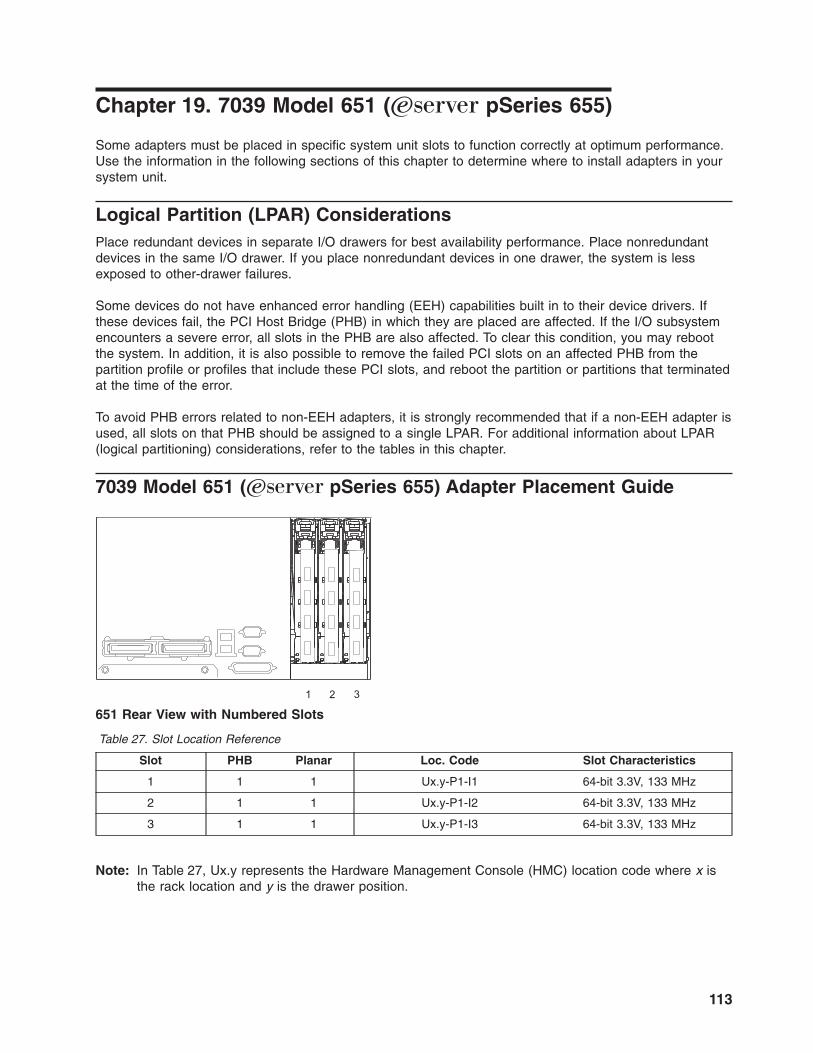
Chapter 19. 7039 Model 651 (Eserver pSeries 655)
Some adapters must be placed in specific system unit slots to function correctly at optimum performance.
Use the information in the following sections of this chapter to determine where to install adapters in your
system unit.
Logical Partition (LPAR) Considerations
Place redundant devices in separate I/O drawers for best availability performance. Place nonredundant
devices in the same I/O drawer. If you place nonredundant devices in one drawer, the system is less
exposed to other-drawer failures.
Some devices do not have enhanced error handling (EEH) capabilities built in to their device drivers. If
these devices fail, the PCI Host Bridge (PHB) in which they are placed are affected. If the I/O subsystem
encounters a severe error, all slots in the PHB are also affected. To clear this condition, you may reboot
the system. In addition, it is also possible to remove the failed PCI slots on an affected PHB from the
partition profile or profiles that include these PCI slots, and reboot the partition or partitions that terminated
at the time of the error.
To avoid PHB errors related to non-EEH adapters, it is strongly recommended that if a non-EEH adapter is
used, all slots on that PHB should be assigned to a single LPAR. For additional information about LPAR
(logical partitioning) considerations, refer to the tables in this chapter.
7039 Model 651 (Eserver pSeries 655) Adapter Placement Guide
1 2 3
651 Rear View with Numbered Slots
Table 27. Slot Location Reference
Slot PHB Planar Loc. Code Slot Characteristics
1 1 1 Ux.y-P1-I1 64-bit 3.3V, 133 MHz
2 1 1 Ux.y-P1-I2 64-bit 3.3V, 133 MHz
3 1 1 Ux.y-P1-I3 64-bit 3.3V, 133 MHz
Note: In Table 27, Ux.y represents the Hardware Management Console (HMC) location code where x is
the rack location and y is the drawer position.
113

1 2 4 5 6 7 8 9 10 11 12 13 14 15 16 17 18 19 203
61D Rear View with Numbered Slots
Table 28. Slot Location Reference
Slot PHB Planar Loc. CodeSee note 2.
Slot Characteristics (FC
6563)
Slot Characteristics(FC 6571)
1 1 1 Ux.y-P1-I1 64-bit 3.3V, 33/66 MHz 64-bit 3.3V, 66/133 MHz
2 1 1 Ux.y-P1-I2 64-bit 3.3V, 33/66 MHz 64-bit 3.3V, 66/133 MHz
3 1 1 Ux.y-P1-I3 64-bit 3.3V, 33/66 MHz 64-bit 3.3V, 66/133 MHz
4 1 1 Ux.y-P1-I4 64-bit 3.3V, 33/66 MHz 64-bit 3.3V, 66/133 MHz
5 2 1 Ux.y-P1-I5 64-bit 3.3V, 33/66 MHz 64-bit 3.3V, 66/133 MHz
6 2 1 Ux.y-P1-I6 64-bit 3.3V, 33/66 MHz 64-bit 3.3V, 66/133 MHz
7 2 1 Ux.y-P1-I7 64-bit 3.3V, 33/66 MHz 64-bit 3.3V, 66/133 MHz
See note1. 2 1 Ux.y-P1-Z1 64-bit 3.3V, 33/66 MHz 64-bit 3.3V, 66/133 MHz
8 3 1 Ux.y-P1-I8 64-bit 5V, 33 MHz 64-bit 3.3V, 66/133 MHz
9 3 1 Ux.y-P1-I9 64-bit 5V, 33 MHz 64-bit 3.3V, 66/133 MHz
10 3 1 Ux.y-P1-I10 64-bit 5V, 33 MHz 64-bit 3.3V, 66/133 MHz
See note1. 3 1 Ux.y-P1-Z2 64-bit 5V, 33 MHz 64-bit 3.3V, 66/133 MHz
11 1 2 Ux.y-P2-I1 64-bit 3.3V, 33/66 MHz 64-bit 3.3V, 66/133 MHz
12 1 2 Ux.y-P2-I2 64-bit 3.3V, 33/66 MHz 64-bit 3.3V, 66/133 MHz
13 1 2 Ux.y-P2-I3 64-bit 3.3V, 33/66 MHz 64-bit 3.3V, 66/133 MHz
14 1 2 Ux.y-P2-I4 64-bit 3.3V, 33/66 MHz 64-bit 3.3V, 66/133 MHz
15 2 2 Ux.y-P2-I5 64-bit 3.3V, 33/66 MHz 64-bit 3.3V, 66/133 MHz
16 2 2 Ux.y-P2-I6 64-bit 3.3V, 33/66 MHz 64-bit 3.3V, 66/133 MHz
17 2 2 Ux.y-P2-I7 64-bit 3.3V, 33/66 MHz 64-bit 3.3V, 66/133 MHz
See note1. 2 2 Ux.y-P2-Z1 64-bit 3.3V, 33/66 MHz 64-bit 3.3V, 66/133 MHz
18 3 2 Ux.y-P2-I8 64-bit 5V, 33 MHz 64-bit 3.3V, 66/133 MHz
19 3 2 Ux.y-P2-I9 64-bit 5V, 33 MHz 64-bit 3.3V, 66/133 MHz
20 3 2 Ux.y-P2-I10 64-bit 5V, 33 MHz 64-bit 3.3V, 66/133 MHz
See note1. 3 2 Ux.y-P2-Z2 64-bit 5V, 33 MHz 64-bit 3.3V, 66/133 MHz
Notes:
1. Integrated SCSI adapter.
2. Ux.y represents the Hardware Management Console (HMC) location code where x is the rack location
and y is the drawer position.
114 Adapter Placement Reference for AIX

Use the following table to identify specific slot location options for the adapters in your 7039 Model 651
(Eserver pSeries 655) system.
Chapter 19. 7039 Model 651 (Eserver pSeries 655) 115

Tabl
e 29
. S
lot
Loca
tion
Opt
ions
Ad
apte
r S
lot
Usa
ge
for
61D
w
hen
th
ere
are
two
65
1 an
d
on
e 61
DS
ee n
ote
8
on
pag
e 12
6.
Slo
t U
sag
e fo
r 61
D w
hen
th
ere
is
on
e 65
1 w
ith
sin
gle
lo
op
con
nec
tio
n to
o
ne
61D
See
n
ote
9
on
pag
e 12
6.
Slo
t U
sag
e fo
r 61
D w
hen
th
ere
is
on
e 65
1 co
nn
ecti
on
to
o
ne
61D
p
lan
arS
ee n
ote
10
o
n
pag
e 12
6.
Slo
t U
sag
e fo
r 61
D w
hen
th
ere
is
on
e 65
1 an
d o
ne
61D
w
ith
m
ixed
pla
nar
sS
ee n
ote
11
o
n
pag
e 12
7.
Slo
t U
sag
e fo
r o
ne
651
Max
. p
er
61D
Pla
nar
: 65
63 /
6571
Max
. p
er
651
bas
e u
nit
EE
H
Ho
t-P
lug
FC
83
98:
SP
Sw
itch2
P
CI-
X
Atta
chm
ent,
64-b
it,
3.3V
, 1-
slot
If 2
FC
65
71:
13,
3,
15,
5If
mix
ed pl
anar
s: 3,
5
If 2
FC
65
71:
3, 13
, 5,
15
If 2
FC
65
71:
13,
15
3, 5
3, 1
0/2
2 Y
N
FC
57
18:
10
Gig
abit-
SR
E
NE
T,
PC
IX,
32/6
4 bi
t, 3.
3/5v
If 65
71 x
2: 15
, 5,
18,
8, 11
, 1
If m
ixed
pl
anar
s: 5,
8, 1
See
no
te 14
on
page
12
7
If 65
71 x
2: 1,
11
, 5,
15
, 8,
18
See
no
te 14
on
page
12
7
If 65
71 x
2: 11
, 15
, 18
See
no
te 14
on
page
12
7
1, 5,
8
3, 1
0/2
3 Y
Y
FC
57
19:
10
Gig
abit-
LR E
NE
T,
PC
IX,
32/6
4 bi
t, 3.
3v
If 65
71 x
2: 15
, 5,
18,
8, 11
, 1
If m
ixed
pl
anar
s: 5,
8, 1
See
no
te 14
on
page
12
7
If 65
71 x
2: 1,
11
, 5,
15
, 8,
18
See
no
te 14
on
page
12
7
If 65
71 x
2: 11
, 15
, 18
See
no
te 14
on
page
12
7
1, 5,
8
3, 1
0/2
3 Y
Y
FC
62
06:
Sin
gle-
End
ed U
ltra
SC
SI A
dapt
er,
32-b
it, 5V
(T
ype
4-K
)
If 2
FC
65
63:
20,
10If
mix
ed pl
anar
s: 20
If 2
FC
65
63:
10,
20
If 2
FC
65
63:
20
0 0
1/0
0 Y
Y
FC
27
51:
S/3
90
ES
CO
N C
hann
el,
32-b
it, 5V
, (T
ype
5-5)
If 2
FC
65
63:
19,
9,
20,
10If
mix
ed pl
anar
s:
19,
20
If 2
FC
65
63:1
9,
10,
20
If 2
FC
65
63:
19,
20
0 0
2/0
0 Y
Y
116 Adapter Placement Reference for AIX
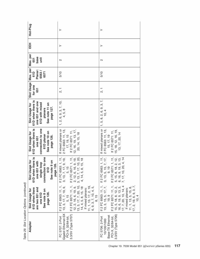
Tabl
e 29
. S
lot
Loca
tion
Opt
ions
(c
ontin
ued)
Ad
apte
r S
lot
Usa
ge
for
61D
w
hen
th
ere
are
two
65
1 an
d
on
e 61
DS
ee n
ote
8
on
pag
e 12
6.
Slo
t U
sag
e fo
r 61
D w
hen
th
ere
is
on
e 65
1 w
ith
sin
gle
lo
op
con
nec
tio
n to
o
ne
61D
See
n
ote
9
on
pag
e 12
6.
Slo
t U
sag
e fo
r 61
D w
hen
th
ere
is
on
e 65
1 co
nn
ecti
on
to
o
ne
61D
p
lan
arS
ee n
ote
10
o
n
pag
e 12
6.
Slo
t U
sag
e fo
r 61
D w
hen
th
ere
is
on
e 65
1 an
d o
ne
61D
w
ith
m
ixed
pla
nar
sS
ee n
ote
11
o
n
pag
e 12
7.
Slo
t U
sag
e fo
r o
ne
651
Max
. p
er
61D
Pla
nar
: 65
63 /
6571
Max
. p
er
651
bas
e u
nit
EE
H
Ho
t-P
lug
FC
57
07:
2-P
ort
Gig
abit
Eth
erne
t-S
X
PC
I-X
, 32
/64-
bit,
3.3/
5V (T
ype
5707
)
If 2
FC
65
63:
11,
1,
13,
3, 17
, 7,
19
, 9,
5, 15
If 2
FC
65
71:
11,
1,
12,
2, 16
, 6,
19
, 9,
13,
3, 17
, 7,
20
, 10
, 14
, 4,
5,
8,
15
, 18
If m
ixed
pl
anar
s:
11,
1, 13
, 17
, 2,
19
, 6,
9,
3,
7,
10
, 4,
5,
8, 15
If 2
FC
65
63:
1, 11
, 3,
13
, 7,
17
, 9,
19
, 5,
15
If 2
FC
65
71:
1, 11
, 2,
12
, 6,
16
, 9,
19
, 3,
13
, 7,
17
, 10
, 20
, 4,
14
, 5,
8,
15
, 18
If m
ixed
pl
anar
s or
2 F
C 65
63:
11,
13,
17,
19,
15If
2 F
C 65
71:
11,
12,
16,
19,
13,
17,
20,
14,
15,
18
1, 2,
6,
9,
3,
7,
10
, 4,
5,
8
2, 1
5/10
2
Y
Y
FC
57
06:
2-P
ort
10/1
00/1
000
Bas
e-T
X E
ther
net
PC
I-X
, 32
/64-
bit,
3.3/
5V (T
ype
5706
)
If 2
FC
65
63:
11,
1,
13,
3, 15
, 5,
17
, 7,
19,
9If
2 F
C 65
71:
11,
1,
15,
5, 18
, 8,
12
, 2,
16,
6, 19
, 9,
13
, 3,
17,
7, 20
, 10
, 14
, 4
If m
ixed
pl
anar
s:
11,
1, 13
, 5,
15
, 8,
17,
2, 19
, 6,
9,
3,
7,
10,
4
If 2
FC
65
63:
1, 11
, 3,
13
, 5,
15
, 7,
17
, 9,
19
If 2
FC
65
71:
1, 11
, 5,
15
, 8,
18
, 2,
12
, 6,
16
, 9,
19
, 3,
13
, 7,
17
, 10
, 20
, 4,
14
If m
ixed
pl
anar
s or
2 F
C 65
63:
11,
13,
15,
17,
19If
2 F
C 65
71:
11,
15,
18,
12,
16,
19,
13,
17,
20,
14
1, 5,
8,
2,
6,
9,
3,
7,
10,
4 2,
1
5/10
2
Y
Y
Chapter 19. 7039 Model 651 (Eserver pSeries 655) 117

Tabl
e 29
. S
lot
Loca
tion
Opt
ions
(c
ontin
ued)
Ad
apte
r S
lot
Usa
ge
for
61D
w
hen
th
ere
are
two
65
1 an
d
on
e 61
DS
ee n
ote
8
on
pag
e 12
6.
Slo
t U
sag
e fo
r 61
D w
hen
th
ere
is
on
e 65
1 w
ith
sin
gle
lo
op
con
nec
tio
n to
o
ne
61D
See
n
ote
9
on
pag
e 12
6.
Slo
t U
sag
e fo
r 61
D w
hen
th
ere
is
on
e 65
1 co
nn
ecti
on
to
o
ne
61D
p
lan
arS
ee n
ote
10
o
n
pag
e 12
6.
Slo
t U
sag
e fo
r 61
D w
hen
th
ere
is
on
e 65
1 an
d o
ne
61D
w
ith
m
ixed
pla
nar
sS
ee n
ote
11
o
n
pag
e 12
7.
Slo
t U
sag
e fo
r o
ne
651
Max
. p
er
61D
Pla
nar
: 65
63 /
6571
Max
. p
er
651
bas
e u
nit
EE
H
Ho
t-P
lug
FC
57
01:
10/1
00/1
000
Bas
e-T
X E
ther
net,
32/6
4-bi
t, 3.
3/5V
If 2
FC
65
63:
11,
1,
13,
3, 15
, 5,
17
, 7,
19,
9If
2 F
C 65
71:
11,
1,
15,
5, 18
, 8,
12
, 2,
16,
6, 19
, 9,
13
, 3,
17,
7, 20
, 10
, 14
, 4
If m
ixed
pl
anar
s:
11,
1, 13
, 5,
15
, 8,
17,
2, 19
, 6,
9,
3,
7,
10,
4
If 2
FC
65
63:
1, 11
, 3,
13
, 5,
15
, 7,
17
, 9,
19
If 2
FC
65
71:
1, 11
, 5,
15
, 8,
18
, 2,
12
, 6,
16
, 9,
19
, 3,
13
, 7,
17
, 10
, 20
, 4,
14
If m
ixed
pl
anar
s or
2 F
C 65
63:
11,
13,
15,
17,
19If
2 F
C 65
71:
11,
15,
18,
12,
16,
19,
13,
17,
20,
14
1, 5,
8,
2,
6,
9,
3,
7,
10,
4 2,
1
5/10
2
Y
Y
FC
57
00:
Gig
abit
Eth
erne
t, 10
00
Bas
e-S
X,
32/6
4-bi
t, 3.
3/5V
If 2
FC
65
63:
11,
1,
13,
3, 15
, 5,
17
, 7,
19,
9If
2 F
C 65
71:
11,
1,
15,
5, 18
, 8,
12
, 2,
16,
6, 19
, 9,
13
, 3,
17,
7, 20
, 10
, 14
, 4
If m
ixed
pl
anar
s:
11,
1, 13
, 5,
15
, 8,
17,
2, 19
, 6,
9,
3,
7,
10,
4
If 2
FC
65
63:
1, 11
, 3,
13
, 5,
15
, 7,
17
, 9,
19
If 2
FC
65
71:
1, 11
, 5,
15
, 8,
18
, 2,
12
, 6,
16
, 9,
19
, 3,
13
, 7,
17
, 10
, 20
, 4,
14
If m
ixed
pl
anar
s or
2 F
C 65
63:1
1, 13
, 15
, 17
, 19
If 2
FC
65
71:
11,
15,
18,
12,
16,
19,
13,
17,
20,
14
1, 5,
8,
2,
6,
9,
3,
7,
10,
4 2,
1
5/10
2
Y
Y
FC
57
14:
ISC
SI
TO
E G
IGA
BIT
EN
ET
(FIB
ER
),
PC
IX/S
HO
RT,
32/6
4BIT
, 3.
3/5V
If 65
63 x
2 or
mix
ed:
11,
1, 15
, 5,
18,
8, 12
, 2,
16
, 6,
19,
9, 13
, 3,
17
, 7,
14,
4, 20
, 10
If 65
71 x
2: 11
, 1,
15,
5, 18
, 8,
12
, 2,
16,
6, 19
, 9,
13
, 3,
17,
7, 20
, 10
, 14
, 4
If 65
63 x
2: 1,
11
, 5,
15
, 8,
18
, 2,
12
, 6,
16
, 9,
19
, 3,
13
, 7,
17
, 4,
14
, 10
, 20
If 65
71 x
2: 1,
11
, 5,
15
, 8,
18
, 2,
12
, 6,
16
, 9,
19
, 3,
13
, 7,
17
, 10
, 20
, 4,
14
If m
ixed
or
65
63 x
2: 11
, 15
, 18
, 12
, 16
, 19
, 13
, 17
, 14
, 20
If 65
71 x
2: 11
, 15
, 18
, 12
, 16
, 19
, 13
, 17
, 20
, 14
1, 5,
8,
2,
6,
9,
3,
7,
10,
4 10
2,
1
2 Y
Y
118 Adapter Placement Reference for AIX

Tabl
e 29
. S
lot
Loca
tion
Opt
ions
(c
ontin
ued)
Ad
apte
r S
lot
Usa
ge
for
61D
w
hen
th
ere
are
two
65
1 an
d
on
e 61
DS
ee n
ote
8
on
pag
e 12
6.
Slo
t U
sag
e fo
r 61
D w
hen
th
ere
is
on
e 65
1 w
ith
sin
gle
lo
op
con
nec
tio
n to
o
ne
61D
See
n
ote
9
on
pag
e 12
6.
Slo
t U
sag
e fo
r 61
D w
hen
th
ere
is
on
e 65
1 co
nn
ecti
on
to
o
ne
61D
p
lan
arS
ee n
ote
10
o
n
pag
e 12
6.
Slo
t U
sag
e fo
r 61
D w
hen
th
ere
is
on
e 65
1 an
d o
ne
61D
w
ith
m
ixed
pla
nar
sS
ee n
ote
11
o
n
pag
e 12
7.
Slo
t U
sag
e fo
r o
ne
651
Max
. p
er
61D
Pla
nar
: 65
63 /
6571
Max
. p
er
651
bas
e u
nit
EE
H
Ho
t-P
lug
FC
57
13:
ISC
SI
TO
E G
IGA
BIT
EN
ET
(C
OP
PE
R),
PC
IX/S
HO
RT,
32/6
4BIT
, 3.
3/5V
If 65
63 x
2 or
mix
ed:
11,
1, 15
, 5,
18,
8, 12
, 2,
16
, 6,
19,
9, 13
, 3,
17
, 7,
14,
4, 20
, 10
If 65
71 x
2: 11
, 1,
15,
5, 18
, 8,
12
, 2,
16,
6, 19
, 9,
13
, 3,
17,
7, 20
, 10
, 14
, 4
If 65
63 x
2: 1,
11
, 5,
15
, 8,
18
, 2,
12
, 6,
16
, 9,
19
, 3,
13
, 7,
17
, 4,
14
, 10
, 20
If 65
71 x
2: 1,
11
, 5,
15
, 8,
18
, 2,
12
, 6,
16
, 9,
19
, 3,
13
, 7,
17
, 10
, 20
, 4,
14
If m
ixed
or
65
63 x
2: 11
, 15
, 18
, 12
, 16
, 19
, 13
, 17
, 14
, 20
If 65
71 x
2: 11
, 15
, 18
, 12
, 16
, 19
, 13
, 17
, 20
, 14
1, 5,
8,
2,
6,
9,
3,
7,
10,
4 10
2,
1
2 Y
Y
FC
57
16:
2GB
FC
AL,
P
CIX
32
/64
bit,
3.3/
5v
If 65
63 x
2: 11
, 1,
15,
5, 12
, 2,
16
, 6,
19,
9, 13
, 3,
17
, 7,
14,
4 If
6571
x
2: 11
, 1,
15,
5, 18
, 8,
12
, 2,
16,
6, 19
, 9,
13
, 3,
17,
7, 20
, 10
, 14
, 4
If m
ixed
: 11
, 1,
15
, 5,
8,
12
, 2,
16
, 6,
9,
13,
3, 17
, 7,
10
, 14
, 4
If 65
63 x
2: 1,
11
, 5,
15
, 2,
12
, 6,
16
, 9,
19
, 3,
13
, 7,
17
, 4,
14
If 65
71 x
2: 1,
11
, 5,
15
, 8,
18
, 2,
12
, 6,
16
, 9,
19
, 3,
13
, 7,
17
, 10
, 20
, 4,
14
If m
ixed
or
65
63 x
2: 11
, 15
, 12
, 16
, 19
, 13
, 17
, 14
If 65
71 x
2: 11
, 15
, 18
, 12
, 16
, 19
, 13
, 17
, 20
, 14
1, 5,
8,
2,
6,
9,
3,
7,
10,
4 5/
10
3, 2,
1
3 Y
Y
FC
62
39:
2 G
igab
it F
ibre
C
hann
el
Ada
pter
, 32
/64-
bit,
3.3V
(T
ype
5704
)S
ee no
te 7
on pa
ge
126.
If 2
FC
65
63:
11,
1,
13,
3, 15
, 5,
17
, 7,
19,
9If
2 F
C 65
71:
11,
1,
15,
5, 18
, 8,
12
, 2,
16,
6, 19
, 9,
13
, 3,
17,
7, 20
, 10
, 14
, 4
If m
ixed
pl
anar
s:
11,
1, 13
, 5,
15
, 8,
17,
2, 19
, 6,
9,
3,
7,
10,
4
If 2
FC
65
63:
1, 11
, 3,
13
, 5,
15
, 7,
17
, 9,
19
If 2
FC
65
71:
1, 11
, 5,
15
, 8,
18
, 2,
12
, 6,
16
, 9,
19
, 3,
13
, 7,
17
, 10
, 20
, 4,
14
If m
ixed
pl
anar
s or
2 F
C 65
63:
11,
13,
15,
17,
19If
2 F
C 65
71:
11,
15,
18,
12,
16,
19,
13,
17,
20,
14
1, 5,
8,
2,
6,
9,
3,
7,
10,
4 3,
2,
1
5/10
3
Y
Y
Chapter 19. 7039 Model 651 (Eserver pSeries 655) 119

Tabl
e 29
. S
lot
Loca
tion
Opt
ions
(c
ontin
ued)
Ad
apte
r S
lot
Usa
ge
for
61D
w
hen
th
ere
are
two
65
1 an
d
on
e 61
DS
ee n
ote
8
on
pag
e 12
6.
Slo
t U
sag
e fo
r 61
D w
hen
th
ere
is
on
e 65
1 w
ith
sin
gle
lo
op
con
nec
tio
n to
o
ne
61D
See
n
ote
9
on
pag
e 12
6.
Slo
t U
sag
e fo
r 61
D w
hen
th
ere
is
on
e 65
1 co
nn
ecti
on
to
o
ne
61D
p
lan
arS
ee n
ote
10
o
n
pag
e 12
6.
Slo
t U
sag
e fo
r 61
D w
hen
th
ere
is
on
e 65
1 an
d o
ne
61D
w
ith
m
ixed
pla
nar
sS
ee n
ote
11
o
n
pag
e 12
7.
Slo
t U
sag
e fo
r o
ne
651
Max
. p
er
61D
Pla
nar
: 65
63 /
6571
Max
. p
er
651
bas
e u
nit
EE
H
Ho
t-P
lug
FC
62
28:
2 G
igab
it F
ibre
C
hann
el
Ada
pter
fo
r 32
/64-
bit,
3.3/
5V
PC
I B
us (T
ype
4-W
) S
ee no
te 7
on pa
ge
126.
If 2
FC
65
63:
11,
1,
13,
3, 15
, 5,
17
, 7,
19,
9If
2 F
C 65
71:
11,
1,
15,
5, 18
, 8,
12
, 2,
16,
6, 19
, 9,
13
, 3,
17,
7, 20
, 10
, 14
, 4
If m
ixed
pl
anar
s:
11,
1, 13
, 5,
15
, 8,
17,
2, 19
, 6,
9,
3,
7,
10,
4
If 2
FC
65
63:
1, 11
, 3,
13
, 5,
15
, 7,
17
, 9,
19
If 2
FC
65
71:
1, 11
, 5,
15
, 8,
18
, 2,
12
, 6,
16
, 9,
19
, 3,
13
, 7,
17
, 10
, 20
, 4,
14
If m
ixed
pl
anar
s or
2 F
C 65
63:
11,
13,
15,
17,
19If
2 F
C 65
71:
11,
15,
18,
12,
16,
19,
13,
17,
20,
14
1, 5,
8,
2,
6,
9,
3,
7,
10,
4 3,
2,
1
5/10
3
Y
Y
FC
57
10:
PC
I-X
Dua
l Cha
nnel
Ultr
a320
S
CS
I B
lind
Sw
ap A
dapt
er,
32/6
4-bi
t, 3.
3V
(Typ
e 57
02)
If 2
FC
65
63:
11,
1,
13,
3, 15
, 5,
17
, 7,
20,
10If
2 F
C 65
71:
11,
1,
15,
5, 18
, 8,
12
, 2,
16,
6, 19
, 9,
13
, 3,
17,
7, 20
, 10
, 14
, 4
If m
ixed
pl
anar
s:
11,
1, 13
, 5,
15
, 8,
17,
2, 19
, 6,
9,
3,
7,
10,
4
If 2
FC
65
63:
1, 11
, 3,
13
, 5,
15
, 7,
17
, 10
, 20
If 2
FC
65
71:
1, 11
, 5,
15
, 8,
18
, 2,
12
, 6,
16
, 9,
19
, 3,
13
, 7,
17
, 10
, 20
, 4,
14
If m
ixed
pl
anar
s or
2 F
C 65
63:
11,
13,
15,
17,
20If
2 F
C 65
71:
11,
15,
18,
12,
16,
19,
13,
17,
20,
14
1, 5,
8,
2,
6,
9,
3,
7,
10,
4 3,
2,
1
5/10
3
Y
Y
120 Adapter Placement Reference for AIX

Tabl
e 29
. S
lot
Loca
tion
Opt
ions
(c
ontin
ued)
Ad
apte
r S
lot
Usa
ge
for
61D
w
hen
th
ere
are
two
65
1 an
d
on
e 61
DS
ee n
ote
8
on
pag
e 12
6.
Slo
t U
sag
e fo
r 61
D w
hen
th
ere
is
on
e 65
1 w
ith
sin
gle
lo
op
con
nec
tio
n to
o
ne
61D
See
n
ote
9
on
pag
e 12
6.
Slo
t U
sag
e fo
r 61
D w
hen
th
ere
is
on
e 65
1 co
nn
ecti
on
to
o
ne
61D
p
lan
arS
ee n
ote
10
o
n
pag
e 12
6.
Slo
t U
sag
e fo
r 61
D w
hen
th
ere
is
on
e 65
1 an
d o
ne
61D
w
ith
m
ixed
pla
nar
sS
ee n
ote
11
o
n
pag
e 12
7.
Slo
t U
sag
e fo
r o
ne
651
Max
. p
er
61D
Pla
nar
: 65
63 /
6571
Max
. p
er
651
bas
e u
nit
EE
H
Ho
t-P
lug
FC
57
11:
PC
I-X
Dua
l Cha
nnel
Ultr
a320
S
CS
I R
AID
B
lind
Sw
ap
Ada
pter
, 32
/64-
bit,
3.3V
(T
ype
5703
)
If 2
FC
65
63:
11,
1,
13,
3, 15
, 5,
17
, 7,
20,
10If
2 F
C 65
71:
11,
1,
15,
5, 18
, 8,
12
, 2,
16,
6, 19
, 9,
13
, 3,
17,
7, 20
, 10
, 14
, 4
If m
ixed
pl
anar
s:
11,
1, 13
, 5,
15
, 8,
17,
2, 19
, 6,
9,
3,
7,
10,
4
If 2
FC
65
63:
1, 11
, 3,
13
, 5,
15
, 7,
17
, 10
, 20
If 2
FC
65
71:
1, 11
, 5,
15
, 8,
18
, 2,
12
, 6,
16
, 9,
19
, 3,
13
, 7,
17
, 10
, 20
, 4,
14
If m
ixed
pl
anar
s or
2 F
C 65
63:
11,
13,
15,
17,
20If
2 F
C 65
71:
11,
15,
18,
12,
16,
19,
13,
17,
20,
14
1, 5,
8,
2,
6,
9,
3,
7,
10,
4 3,
2,
1
5/10
3
Y
Y
FC
62
03:
Dua
l-Cha
nnel
Ultr
a3 S
CS
I, 32
/64-
bit,
3.3/
5V
(Typ
e 4-
Y)
If m
ixed
pl
anar
s or
2 F
C 65
63:
11,
1,
13,
3, 15
, 5,
17
, 7,
(20
or 19
), (1
0 or
9)
If 2
FC
65
71:
11,
1,
15,
5, 18
, 8,
12
, 2,
16,
6, 19
, 9,
13
, 3,
17,
7, 20
, 10
, 14
, 4
If 2
FC
65
63:
1, 11
, 3,
13
, 5,
15
, 7,
17
, (1
0 or
9)
, (2
0 or
19
)If
2 F
C 65
71:
1, 11
, 5,
15
, 8,
18
, 2,
12
, 6,
16
, 9,
19
, 3,
13
, 7,
17
, 10
, 20
, 4,
14
If m
ixed
pl
anar
s or
2 F
C 65
63:
11,
13,
15,
17,
(20
or 19
)If
2 F
C 65
71:
11,
15,
18,
12,
16,
19,
13,
17,
20,
14
1, 5,
8,
2,
6,
9,
3,
7,
10,
4 3,
2,
1
5 3
Y
Y
FC
62
30: A
dvan
ced
Ser
ialR
AID
P
lus,
32-b
it, 3.
3/5V
(T
ype
4-P
)
If m
ixed
pl
anar
s or
2 F
C 65
63:
11,
1,
13,
3, 14
, 4,
15
, 5,
17,
7, 19
, 9
If 2
FC
65
71:
11,
1,
15,
5, 18
, 8,
12
, 2,
16,
6, 19
, 9,
13
, 3,
17,
7, 20
, 10
, 14
, 4
If 2
FC
65
63:
1, 11
, 3,
13
, 4,
14
, 5,
15
, 7,
17
, 9,
19
If 2
FC
65
71:
1, 11
, 5,
15
, 8,
18
, 2,
12
, 6,
16
, 9,
19
, 3,
13
, 7,
17
, 10
, 20
, 4,
14
If m
ixed
pl
anar
s or
2 F
C 65
63:
11,
13,
14,
15,
17,
19If
2 F
C 65
71:
11,
15,
18,
12,
16,
19,
13,
17,
20,
14
1, 5,
8,
2,
6,
9,
3,
7,
10,
4 3,
2,
1
6 2
Y
Y
Chapter 19. 7039 Model 651 (Eserver pSeries 655) 121

Tabl
e 29
. S
lot
Loca
tion
Opt
ions
(c
ontin
ued)
Ad
apte
r S
lot
Usa
ge
for
61D
w
hen
th
ere
are
two
65
1 an
d
on
e 61
DS
ee n
ote
8
on
pag
e 12
6.
Slo
t U
sag
e fo
r 61
D w
hen
th
ere
is
on
e 65
1 w
ith
sin
gle
lo
op
con
nec
tio
n to
o
ne
61D
See
n
ote
9
on
pag
e 12
6.
Slo
t U
sag
e fo
r 61
D w
hen
th
ere
is
on
e 65
1 co
nn
ecti
on
to
o
ne
61D
p
lan
arS
ee n
ote
10
o
n
pag
e 12
6.
Slo
t U
sag
e fo
r 61
D w
hen
th
ere
is
on
e 65
1 an
d o
ne
61D
w
ith
m
ixed
pla
nar
sS
ee n
ote
11
o
n
pag
e 12
7.
Slo
t U
sag
e fo
r o
ne
651
Max
. p
er
61D
Pla
nar
: 65
63 /
6571
Max
. p
er
651
bas
e u
nit
EE
H
Ho
t-P
lug
FC
29
46:
PC
I T
UR
BO
WA
YS
62
2 P
CI
MM
F A
TM
, 64
-bit,
3.
3/5V
(T
ype
A-B
)
If 2
FC
65
63:
11,
1,
13,
3, 15
, 5,
17
, 7,
19,
9If
2 F
C 65
71:
11,
1,
15,
5, 18
, 8,
12
, 2,
16,
6, 19
, 9,
13
, 3,
17,
7, 20
, 10
, 14
, 4
If m
ixed
pl
anar
s:
11,
1, 13
, 5,
15
, 8,
17,
2, 19
, 6,
9,
3,
7,
10,
4
If 2
FC
65
63:
1, 11
, 3,
13
, 5,
15
, 7,
17
, 9,
19
If 2
FC
65
71:
1, 11
, 5,
15
, 8,
18
, 2,
12
, 6,
16
, 9,
19
, 3,
13
, 7,
17
, 10
, 20
, 4,
14
If m
ixed
pl
anar
s or
2 F
C 65
63:
11,
13,
15,
17,
19If
2 F
C 65
71:
11,
15,
18,
12,
16,
19,
13,
17,
20,
14
1, 5,
8,
2,
6,
9,
3,
7,
10,
4 3,
2,
1
5/10
3
Y
Y
FC
62
04:
PC
I U
nive
rsal
Diff
eren
tial U
ltra
SC
SI,
32-b
it, 3.
3/5V
(Typ
e 4-
U)
20,
10,
19,
9, 18
, 8,
17,
7, 16
, 6,
15
, 5,
14,
4, 13
, 3,
12
, 2,
11,
1
10,
20,
9, 19
, 8,
18
, 7,
17
, 6,
16
, 5,
15
, 4,
14
, 3,
13
, 2,
12
, 1,
11
20,
19,
18,
17,
16,
15,
14,
13,
12,
11
10,
9, 8,
7,
6,
5,
4,
3, 2,
1
1, 2,
3
5 3
Y
Y
FC
28
49:
PO
WE
R
GX
T13
5P G
raph
ics
Acc
eler
ator
, 32
-bit,
3.3/
5V (T
ype
2849
)
(15,
16
, 17
); (5
, 6,
7);
(11,
12
, 13
, 14
);
(1,
2, 3,
4)
; (1
8, 19
, 20
); (8
, 9,
10
)S
ee no
te 3
on pa
ge
126.
(5,
6, 7)
; (1
5, 16
, 17
); (1
, 2,
3,
4)
; (1
1, 12
, 13
, 14
); (8
, 9,
10
); (1
8, 19
, 20
)S
ee no
te 3
on pa
ge
126.
(15,
16
, 17
); (1
1,
12,
13,
14);
(1
8, 19
, 20
)S
ee no
te 3
on pa
ge
126.
(5,
6, 7)
; (1
, 2,
3,
4);
(8,
9, 10
) 1,
2,
3
2 1
Y
N
FC
28
48:
GX
T13
5P
Gra
phic
s A
dapt
er,
32-b
it, 3.
3/5V
(T
ype
1-X
)
(15,
16
, 17
); (5
, 6,
7);
(11,
12
, 13
, 14
);
(1,
2, 3,
4)
; (1
8, 19
, 20
); (8
, 9,
10
)S
ee no
te 3
on pa
ge
126.
(5,
6, 7)
; (1
5, 16
, 17
); (1
, 2,
3,
4)
; (1
1, 12
, 13
, 14
); (8
, 9,
10
); (1
8, 19
, 20
)S
ee no
te 3
on pa
ge
126.
(15,
16
, 17
); (1
1,
12,
13,
14);
(1
8, 19
, 20
)S
ee no
te 3
on pa
ge
126.
(5,
6, 7)
; (1
, 2,
3,
4);
(8,
9, 10
) 1,
2,
3
2 1
Y
N
122 Adapter Placement Reference for AIX

Tabl
e 29
. S
lot
Loca
tion
Opt
ions
(c
ontin
ued)
Ad
apte
r S
lot
Usa
ge
for
61D
w
hen
th
ere
are
two
65
1 an
d
on
e 61
DS
ee n
ote
8
on
pag
e 12
6.
Slo
t U
sag
e fo
r 61
D w
hen
th
ere
is
on
e 65
1 w
ith
sin
gle
lo
op
con
nec
tio
n to
o
ne
61D
See
n
ote
9
on
pag
e 12
6.
Slo
t U
sag
e fo
r 61
D w
hen
th
ere
is
on
e 65
1 co
nn
ecti
on
to
o
ne
61D
p
lan
arS
ee n
ote
10
o
n
pag
e 12
6.
Slo
t U
sag
e fo
r 61
D w
hen
th
ere
is
on
e 65
1 an
d o
ne
61D
w
ith
m
ixed
pla
nar
sS
ee n
ote
11
o
n
pag
e 12
7.
Slo
t U
sag
e fo
r o
ne
651
Max
. p
er
61D
Pla
nar
: 65
63 /
6571
Max
. p
er
651
bas
e u
nit
EE
H
Ho
t-P
lug
FC
27
37:
Key
boar
d /
Mou
se A
ttach
men
t C
ard
- P
CI,
32-b
it,
3.3/
5V
Pai
red
with
F
C
2848
an
d F
C 28
49.
Pai
red
with
F
C
2848
an
d F
C 28
49.
Pai
red
with
F
C
2848
an
d F
C 28
49.
Pai
red
with
F
C
2848
an
d F
C 28
49.
1, 2,
3
2 1
Y
N
FC
27
33:
Ser
ial
HIP
PI,
Long
-Wav
e O
ptic
s (T
ype
9-W
)
11,
1, 12
, 2,
13
, 3,
14,
4, 15
, 5,
16
, 6,
17,
7, 18
, 8,
19
, 9,
20,
10
1, 11
, 2,
12
, 3,
13
, 4,
14
, 5,
15
, 6,
16
, 7,
17
, 8,
18
, 9,
19
, 10
, 20
11,
12,
13,
14,
15,
16,
17,
18,
19,
20
1, 2,
3,
4,
5,
6,
7,
8,
9, 10
0 2
0 Y
Y
FC
27
32:
Ser
ial
HIP
PI,
Sho
rt-W
ave
Opt
ics
(Typ
e 9-
W)
11,
1, 12
, 2,
13
, 3,
14,
4, 15
, 5,
16
, 6,
17,
7, 18
, 8,
19
, 9,
20,
10
1, 11
, 2,
12
, 3,
13
, 4,
14
, 5,
15
, 6,
16
, 7,
17
, 8,
18
, 9,
19
, 10
, 20
11,
12,
13,
14,
15,
16,
17,
18,
19,
20
1, 2,
3,
4,
5,
6,
7,
8,
9, 10
0 2
0 Y
Y
FC
49
62:
Eth
erne
t/LA
N
Enc
rypt
ion
10/1
00B
aseT
, 32
-bit,
3.
3/5V
(T
ype
A-F
)
11,
1, 12
, 2,
13
, 3,
14,
4, 15
, 5,
16
, 6,
17,
7, 18
, 8,
19
, 9,
20,
10
1, 11
, 2,
12
, 3,
13
, 4,
14
, 5,
15
, 6,
16
, 7,
17
, 8,
18
, 9,
19
, 10
, 20
11,
12,
13,
14,
15,
16,
17,
18,
19,
20
1, 2,
3,
4,
5,
6,
7,
8,
9, 10
1, 2,
3
10
3 Y
Y
FC
49
61:
10/1
00
4-P
ort
Eth
erne
t, 32
/64-
bit,
3.3/
5V
(Typ
e A
-E)
11,
1, 12
, 2,
13
, 3,
14,
4, 15
, 5,
16
, 6,
17,
7, 18
, 8,
19
, 9,
20,
10
1, 11
, 2,
12
, 3,
13
, 4,
14
, 5,
15
, 6,
16
, 7,
17
, 8,
18
, 9,
19
, 10
, 20
11,
12,
13,
14,
15,
16,
17,
18,
19,
20
1, 2,
3,
4,
5,
6,
7,
8,
9, 10
1, 2,
3
5/10
3
Y
Y
FC
29
43:
8-P
ort
Asy
nchr
onou
s E
IA-2
32E
/RS
-422
A
PC
I, 32
-bit,
3.
3/5V
(Typ
e 3-
B)
20,
10,
19,
9, 18
, 8,
17,
7, 16
, 6,
15
, 5,
14,
4, 13
, 3,
12
, 2,
11,
1
10,
20,
9, 19
, 8,
18
, 7,
17
, 6,
16
, 5,
15
, 4,
14
, 3,
13
, 2,
12
, 1,
11
20,
19,
18,
17,
16,
15,
14,
13,
12,
11
10,
9, 8,
7,
6,
5,
4,
3, 2,
1
0 4
0 Y
Y
Chapter 19. 7039 Model 651 (Eserver pSeries 655) 123

Tabl
e 29
. S
lot
Loca
tion
Opt
ions
(c
ontin
ued)
Ad
apte
r S
lot
Usa
ge
for
61D
w
hen
th
ere
are
two
65
1 an
d
on
e 61
DS
ee n
ote
8
on
pag
e 12
6.
Slo
t U
sag
e fo
r 61
D w
hen
th
ere
is
on
e 65
1 w
ith
sin
gle
lo
op
con
nec
tio
n to
o
ne
61D
See
n
ote
9
on
pag
e 12
6.
Slo
t U
sag
e fo
r 61
D w
hen
th
ere
is
on
e 65
1 co
nn
ecti
on
to
o
ne
61D
p
lan
arS
ee n
ote
10
o
n
pag
e 12
6.
Slo
t U
sag
e fo
r 61
D w
hen
th
ere
is
on
e 65
1 an
d o
ne
61D
w
ith
m
ixed
pla
nar
sS
ee n
ote
11
o
n
pag
e 12
7.
Slo
t U
sag
e fo
r o
ne
651
Max
. p
er
61D
Pla
nar
: 65
63 /
6571
Max
. p
er
651
bas
e u
nit
EE
H
Ho
t-P
lug
FC
49
57:
64-b
it/66
MH
z P
CI
AT
M 15
5 M
MF,
3.3/
5V (T
ype
A-D
)
20,
10,
19,
9, 18
, 8,
17,
7, 16
, 6,
15
, 5,
14,
4, 13
, 3,
12
, 2,
11,
1
10,
20,
9, 19
, 8,
18
, 7,
17
, 6,
16
, 5,
15
, 4,
14
, 3,
13
, 2,
12
, 1,
11
20,
19,
18,
17,
16,
15,
14,
13,
12,
11
10,
9, 8,
7,
6,
5,
4,
3, 2,
1
1, 2,
3
10
3 Y
Y
FC
49
53:
64-b
it/66
MH
z P
CI
AT
M 15
5 U
TP,
3.3/
5V (T
ype
A-C
)
20,
10,
19,
9, 18
, 8,
17,
7, 16
, 6,
15
, 5,
14,
4, 13
, 3,
12
, 2,
11,
1
10,
20,
9, 19
, 8,
18
, 7,
17
, 6,
16
, 5,
15
, 4,
14
, 3,
13
, 2,
12
, 1,
11
20,
19,
18,
17,
16,
15,
14,
13,
12,
11
10,
9, 8,
7,
6,
5,
4,
3, 2,
1
1, 2,
3
10
3 Y
Y
FC
29
44:
128-
Por
t A
sync
C
ontr
olle
r P
CI,
32-b
it, 3.
3/5V
(Typ
e 3-
C)
20,
10,
19,
9, 18
, 8,
17,
7, 16
, 6,
15
, 5,
14,
4, 13
, 3,
12
, 2,
11,
1
10,
20,
9, 19
, 8,
18
, 7,
17
, 6,
16
, 5,
15
, 4,
14
, 3,
13
, 2,
12
, 1,
11
20,
19,
18,
17,
16,
15,
14,
13,
12,
11
10,
9, 8,
7,
6,
5,
4,
3, 2,
1
0 10
0
Y
Y
FC
49
59:
Hig
h-S
peed
To
ken
Rin
g P
CI,
32-b
it,
3.3/
5V (T
ype
9-Y
)
20,
10,
19,
9, 18
, 8,
17,
7, 16
, 6,
15
, 5,
14,
4, 13
, 3,
12
, 2,
11,
1
10,
20,
9, 19
, 8,
18
, 7,
17
, 6,
16
, 5,
15
, 4,
14
, 3,
13
, 2,
12
, 1,
11
20,
19,
18,
17,
16,
15,
14,
13,
12,
11
10,
9, 8,
7,
6,
5,
4,
3, 2,
1
1, 2,
3
10
3 Y
Y
FC
27
42:
Sys
Kon
nect
SK
-NE
T F
DD
I-LP
DA
S P
CI,
32-b
it,
3.3/
5V N
o ty
pe
labe
l.
20,
10,
19,
9, 18
, 8,
17,
7, 16
, 6,
15
, 5,
14,
4, 13
, 3,
12
, 2,
11,
1
10,
20,
9, 19
, 8,
18
, 7,
17
, 6,
16
, 5,
15
, 4,
14
, 3,
13
, 2,
12
, 1,
11
20,
19,
18,
17,
16,
15,
14,
13,
12,
11
10,
9, 8,
7,
6,
5,
4,
3, 2,
1
0 4
0 N
Y
FC
27
41:
Sys
Kon
nect
SK
-NE
T F
DD
I-LP
SA
S P
CI,
32-b
it,
3.3/
5V N
o ty
pe
labe
l.
20,
10,
19,
9, 18
, 8,
17,
7, 16
, 6,
15
, 5,
14,
4, 13
, 3,
12
, 2,
11,
1
10,
20,
9, 19
, 8,
18
, 7,
17
, 6,
16
, 5,
15
, 4,
14
, 3,
13
, 2,
12
, 1,
11
20,
19,
18,
17,
16,
15,
14,
13,
12,
11
10,
9, 8,
7,
6,
5,
4,
3, 2,
1
0 4
0 N
Y
124 Adapter Placement Reference for AIX

Tabl
e 29
. S
lot
Loca
tion
Opt
ions
(c
ontin
ued)
Ad
apte
r S
lot
Usa
ge
for
61D
w
hen
th
ere
are
two
65
1 an
d
on
e 61
DS
ee n
ote
8
on
pag
e 12
6.
Slo
t U
sag
e fo
r 61
D w
hen
th
ere
is
on
e 65
1 w
ith
sin
gle
lo
op
con
nec
tio
n to
o
ne
61D
See
n
ote
9
on
pag
e 12
6.
Slo
t U
sag
e fo
r 61
D w
hen
th
ere
is
on
e 65
1 co
nn
ecti
on
to
o
ne
61D
p
lan
arS
ee n
ote
10
o
n
pag
e 12
6.
Slo
t U
sag
e fo
r 61
D w
hen
th
ere
is
on
e 65
1 an
d o
ne
61D
w
ith
m
ixed
pla
nar
sS
ee n
ote
11
o
n
pag
e 12
7.
Slo
t U
sag
e fo
r o
ne
651
Max
. p
er
61D
Pla
nar
: 65
63 /
6571
Max
. p
er
651
bas
e u
nit
EE
H
Ho
t-P
lug
FC
29
62:
2-P
ort
Mul
tipro
toco
l PC
II,
32-b
it, 3.
3/5V
(T
ype
9-V
)
If 2
FC
65
63:
20,
10,
19,
9, 18
, 8
If 2
FC
65
71:
20,
10,
19,
9, 18
, 8,
17
, 7,
16
, 6,
15
, 5,
14
, 4,
13
, 3,
12
, 2,
11
, 1
If m
ixed
pl
anar
s:
20,
19,
18,
10,
9, 8,
7, 6,
5,
4,
3,
2,
1
If 2
FC
65
63:
10,
20,
9, 19
, 8,
18
If 2
FC
65
71:
10,
20,
9, 19
, 8,
18
, 7,
17,
6, 16
, 5,
15
, 4,
14,
3, 13
, 2,
12
, 1,
11
If m
ixed
pl
anar
s or
2 F
C 65
63:
20,
19,
18If
2 F
C 65
71:
20,
19,
18,
17,
16,
15,
14,
13,
12,
11
10,
9, 8,
7,
6,
4,
3,
2, 1
0 3
0 Y
Y
FC
29
47:
IBM
AR
TIC
960H
x 4-
Por
t S
elec
tabl
e P
CI,
32-b
it, 3.
3/5V
(T
ype
9-R
)
20,
10,
19,
9, 18
, 8,
17,
7, 16
, 6,
15
, 5,
14,
4, 13
, 3,
12
, 2,
11,
1
10,
20,
9, 19
, 8,
18
, 7,
17
, 6,
16
, 5,
15
, 4,
14
, 3,
13
, 2,
12
, 1,
11
20,
19,
18,
17,
16,
15,
14,
13,
12,
11
10,
9, 8,
7,
6,
4,
3,
2, 1
1, 2,
3
8 3
Y
Y
FC
49
60:
IBM
Cry
ptog
raph
ic
Acc
eler
ator
, 32
-bit,
3.3/
5V (T
ype
6-J)
20,
10,
19,
9, 18
, 8,
17,
7, 16
, 6,
15
, 5,
14,
4, 13
, 3,
12
, 2,
11,
1
10,
20,
9, 19
, 8,
18
, 7,
17
, 6,
16
, 5,
15
, 4,
14
, 3,
13
, 2,
12
, 1,
11
20,
19,
18,
17,
16,
15,
14,
13,
12,
11
10,
9, 8,
7,
6,
5,
4,
3, 2,
1
1, 2,
3
4 1
Y
Y
See
no
te 2
on pa
ge
126.
FC
49
63:
Cry
ptog
raph
ic
Cop
roce
ssor
, F
IPS
-4,
32-b
it,
3.3/
5V (T
ype
6-I)
20,
10,
19,
9, 18
, 8,
17,
7, 16
, 6,
15
, 5,
14,
4, 13
, 3,
12
, 2,
11,
1
10,
20,
9, 19
, 8,
18
, 7,
17
, 6,
16
, 5,
15
, 4,
14
, 3,
13
, 2,
12
, 1,
11
20,
19,
18,
17,
16,
15,
14,
13,
12,
11
10,
9, 8,
7,
6,
5,
4,
3, 2,
1
1, 2,
3
4 3
Y
Y
See
no
te 1
on pa
ge
126.
Chapter 19. 7039 Model 651 (Eserver pSeries 655) 125

Notes:
1. Before hot-plugging this adapter, see the installation chapter in the PCI Cryptographic Coprocessor
Installation and Using Guide (SA23-1235) for the required procedures.
2. Before hot-plugging this adapter, see the installation chapter in the PCI Cryptographic Accelerator
Installation and Using Guide (SA23-1254) for the required procedures.
3. FC 2848: GXT135P Graphics Adapter, 32-bit, 3.3/5V (Type 1-X) and FC 2737: Keyboard / Mouse
Attachment Card - PCI, 32-bit, 3.3/5V must be placed on the same PHB. All other adapters on that
PHB must be on the same LPAR.
4. FC 3145: Remote I/O Cable, 0.5 M, is used to connect between the left and right sections of an I/O
drawer containing multiple I/O sections. It can also be used to connect two adjacent I/O drawers.
5. This column of the table addresses the case when only one side (slots 11 through 20) of a 61D I/O
drawer is connected to a 651 drawer. If more than 10 adapters are present, use both sides of the
61D I/O drawer, and refer to one of the other slot usage columns for the 61D drawer (listed in this
table).
6. High performance adapters that are installed in FC 6563: I/O Drawer PCI Planar, 10 Slot, 2 Integrated
Ultra3 SCSI Ports have the following limitations:
v 2 per first PHB on each planar
v 2 per second PHB on each planar
v 1 per third PHB on each planar
7. High performance adapters that are installed in FC 6571: I/O Drawer PCI-X Planar, 10 Slot, 2
Integrated Ultra3 SCSI Ports have the following limitations:
v 3 per first PHB on each planar
v 3 per second PHB on each planar
v 2 per third PHB on each planar
8. This configuration represents one 61D with one planar connected to one 651 and a second 61D
planar connected to second 651. The following list contains features that may be present in this
configuration:
v Two FC FC 6563: I/O Drawer PCI Planar, 10 Slot, 2 Integrated Ultra3 SCSI Ports and four FC
3164: RIO to RIO-2 Remote I/O Cable, 1.0M or FC 3165: RIO to RIO-2 Remote I/O Cable, 3.0M
v Two FC 6571: I/O Drawer PCI-X Planar, 10 Slot, 2 Integrated Ultra3 SCSI Ports and four FC 3146:
RIO-2 (Remote I/O-2) Cable, 1.2M or FC 3168: RIO-2 (Remote I/O-2) Cable, 2.5M
v One FC 6563: I/O Drawer PCI Planar, 10 Slot, 2 Integrated Ultra3 SCSI Ports and one FC 6571:
I/O Drawer PCI-X Planar, 10 Slot, 2 Integrated Ultra3 SCSI Ports (mixed planars) and two FC
3164: RIO to RIO-2 Remote I/O Cable, 1.0M or two FC 3165: RIO to RIO-2 Remote I/O Cable,
3.0M and two FC 3146: RIO-2 (Remote I/O-2) Cable, 1.2M or two FC 3168: RIO-2 (Remote I/O-2)
Cable, 2.5M
9. This configuration represents one 61D with both planars connected to one 651 by a single loop. A
single-loop connection cannot be used with mixed planars. The following list contains features that
may be present in this configuration:
v Two FC FC 6563: I/O Drawer PCI Planar, 10 Slot, 2 Integrated Ultra3 SCSI Ports, two FC 3164:
RIO to RIO-2 Remote I/O Cable, 1.0M or FC 3165: RIO to RIO-2 Remote I/O Cable, 3.0M, and
one FC 3145: Remote I/O Cable, 0.5 M
v Two FC 6571: I/O Drawer PCI-X Planar, 10 Slot, 2 Integrated Ultra3 SCSI Ports and three FC
3146: RIO-2 (Remote I/O-2) Cable, 1.2M
v Two FC 6571: I/O Drawer PCI-X Planar, 10 Slot, 2 Integrated Ultra3 SCSI Ports, one FC 3146:
RIO-2 (Remote I/O-2) Cable, 1.2M, and two FC 3168: RIO-2 (Remote I/O-2) Cable, 2.5M
10. This configuration represents one 61D with one planar (slots 11 to 20) connected to one 651. The
following list contains features that may be present in this configuration:
v Two FC FC 6563: I/O Drawer PCI Planar, 10 Slot, 2 Integrated Ultra3 SCSI Ports and two FC
3164: RIO to RIO-2 Remote I/O Cable, 1.0M or FC 3165: RIO to RIO-2 Remote I/O Cable, 3.0M
126 Adapter Placement Reference for AIX

v Two FC 6571: I/O Drawer PCI-X Planar, 10 Slot, 2 Integrated Ultra3 SCSI Ports and two FC 3146:
RIO-2 (Remote I/O-2) Cable, 1.2M or FC 3168: RIO-2 (Remote I/O-2) Cable, 2.5M
v One FC 6563: I/O Drawer PCI Planar, 10 Slot, 2 Integrated Ultra3 SCSI Ports and one FC 6571:
I/O Drawer PCI-X Planar, 10 Slot, 2 Integrated Ultra3 SCSI Ports (mixed planars) and two FC
3164: RIO to RIO-2 Remote I/O Cable, 1.0M or FC 3165: RIO to RIO-2 Remote I/O Cable, 3.0M
11. This configuration represents one 61D with mixed planars (slots 1 to 10) connected to one 651. This
configuration contains one FC 6563: I/O Drawer PCI Planar, 10 Slot, 2 Integrated Ultra3 SCSI Ports,
one FC 6571: I/O Drawer PCI-X Planar, 10 Slot, 2 Integrated Ultra3 SCSI Ports, and two FC 3146:
RIO-2 (Remote I/O-2) Cable, 1.2M or FC 3168: RIO-2 (Remote I/O-2) Cable, 2.5M
12. FC 5718: 10 Gigabit-SR ENET, PCIX, 32/64 bit, 3.3/5v and FC 5719: 10 Gigabit-LR ENET, PCIX,
32/64 bit, 3.3v:
v Cumulative sum of 5718 and 5719 le 2 for CEC + B & C (system) per 8 Way (i.e.: Max =2 for 8
way configurations, Max =4 for 16 way, Max =6 for 24 way and Max =8 for 32 way)
v Cumulative sum of 5718 and 5719 le 1 per B and C. Max of 1 can be placed in a B & C
v No other adapters from the high performance adapters group are allowed in the same PHB as
5718 or 5719.
v FC 5718 and FC 5719 are not supported in 6563 planar.
13. For optimum performance, a maximum of three gigabit ethernet ports per PHB is allowed.
14. FC 5718 and FC 5719 must follow the following requirements:
v No FC 5718 adapters are allowed in two-way I/O drawer systems.
v A total of one FC 5718 adapter is allowed in four- or six-way I/O drawer systems.
v A total of two FC 5718 adapters are allowed in eight-way I/O drawer systems.
v If using a FC 5718 adapter, no other high-performance adapters may be installed on the same
PHB.
Chapter 19. 7039 Model 651 (Eserver pSeries 655) 127

128 Adapter Placement Reference for AIX

Chapter 20. 7040 Model 61D (Eserver pSeries 670)
Adapter cards for the 7040 Model 61D (Eserver pSeries 670) plug into PCI adapter slots in the left or
right side of the I/O subsystem (some system configurations contain only the left side PCI adapter slots).
Each drawer is capable of handling up to 20 PCI adapters. Slots 1 through 7 and 11 through 17 have 3.3V
signaling and can support 33MHz or 66MHz operation depending on the adapter’s capability. 5V only
adapters cannot be used in these slots. Slots 8, 9, 10 and 18,19, 20 have 5V signaling and can only run at
33MHz. 5V only adapters must use these slots. All slots provide both 3.3V and 5V power for the adapters.
129

1 2 4 5 6 7 8 9 10 11 12 13 14 15 16 17 18 19 203
Table 30. Slot Location Reference
Slot PHB Planar Loc. CodeSee note 2.
Slot Characteristics(FC 6563)
Slot Characteristics(FC 6571)
1 1 1 Ux.y-P1-I1 64-bit 3.3V, 33/66 MHz 64-bit 3.3V, 66/133 MHz
2 1 1 Ux.y-P1-I2 64-bit 3.3V, 33/66 MHz 64-bit 3.3V, 66/133 MHz
3 1 1 Ux.y-P1-I3 64-bit 3.3V, 33/66 MHz 64-bit 3.3V, 66/133 MHz
4 1 1 Ux.y-P1-I4 64-bit 3.3V, 33/66 MHz 64-bit 3.3V, 66/133 MHz
5 2 1 Ux.y-P1-I5 64-bit 3.3V, 33/66 MHz 64-bit 3.3V, 66/133 MHz
6 2 1 Ux.y-P1-I6 64-bit 3.3V, 33/66 MHz 64-bit 3.3V, 66/133 MHz
7 2 1 Ux.y-P1-I7 64-bit 3.3V, 33/66 MHz 64-bit 3.3V, 66/133 MHz
See note1. 2 1 Ux.y-P1-Z1 64-bit 3.3V, 33/66 MHz 64-bit 3.3V, 66/133 MHz
8 3 1 Ux.y-P1-I8 64-bit 5V, 33 MHz 64-bit 3.3V, 66/133 MHz
9 3 1 Ux.y-P1-I9 64-bit 5V, 33 MHz 64-bit 3.3V, 66/133 MHz
10 3 1 Ux.y-P1-I10 64-bit 5V, 33 MHz 64-bit 3.3V, 66/133 MHz
See note1. 3 1 Ux.y-P1-Z2 64-bit 5V, 33 MHz 64-bit 3.3V, 66/133 MHz
11 1 2 Ux.y-P2-I1 64-bit 3.3V, 33/66 MHz 64-bit 3.3V, 66/133 MHz
12 1 2 Ux.y-P2-I2 64-bit 3.3V, 33/66 MHz 64-bit 3.3V, 66/133 MHz
13 1 2 Ux.y-P2-I3 64-bit 3.3V, 33/66 MHz 64-bit 3.3V, 66/133 MHz
14 1 2 Ux.y-P2-I4 64-bit 3.3V, 33/66 MHz 64-bit 3.3V, 66/133 MHz
15 2 2 Ux.y-P2-I5 64-bit 3.3V, 33/66 MHz 64-bit 3.3V, 66/133 MHz
16 2 2 Ux.y-P2-I6 64-bit 3.3V, 33/66 MHz 64-bit 3.3V, 66/133 MHz
17 2 2 Ux.y-P2-I7 64-bit 3.3V, 33/66 MHz 64-bit 3.3V, 66/133 MHz
See note1. 2 2 Ux.y-P2-Z1 64-bit 3.3V, 33/66 MHz 64-bit 3.3V, 66/133 MHz
18 3 2 Ux.y-P2-I8 64-bit 5V, 33 MHz 64-bit 3.3V, 66/133 MHz
19 3 2 Ux.y-P2-I9 64-bit 5V, 33 MHz 64-bit 3.3V, 66/133 MHz
20 3 2 Ux.y-P2-I10 64-bit 5V, 33 MHz 64-bit 3.3V, 66/133 MHz
See note1. 3 2 Ux.y-P2-Z2 64-bit 5V, 33 MHz 64-bit 3.3V, 66/133 MHz
Notes:
1. Integrated SCSI adapter.
2. Ux.y represents the Hardware Management Console (HMC) location code where x is the rack location
and y is the drawer position.
130 Adapter Placement Reference for AIX

Use the preceding illustration to identify slot locations described in Table 31 on page 132. The first adapter
from an adapter group is placed in the first slot (per the table) in the drawer. After the first slot selection
has been used, use the second slot in the list. If a designated slot is filled, move to the next available slot.
Note: The default configuration of a 7040 Model 61D (Eserver pSeries 670)’s I/O Subsystem contains
only one Planar in the drawer. If your system contains only Planar 1, then ignore the slot
restrictions listed in Table 31 on page 132 for Planar 2 (P2-I).
Logical Partition (LPAR) Considerations
Place redundant devices in separate I/O drawers for best availability performance. Place nonredundant
devices in the same I/O drawer. If you place nonredundant devices in one drawer, the system is less
exposed to other-drawer failures.
Some devices do not have enhanced error handling (EEH) capabilities built in to their device drivers. If
these devices fail, the PCI Host Bridge (PHB) in which they are placed are affected. If the I/O subsystem
encounters a severe error, all slots in the PHB are also affected. To clear this condition, you may reboot
the system. In addition, it is also possible to remove the failed PCI slots on an affected PHB from the
partition profile or profiles that include these PCI slots, and reboot the partition or partitions that terminated
at the time of the error.
To avoid PHB errors related to non-EEH adapters, it is strongly recommended that if a non-EEH adapter is
used, all slots on that PHB should be assigned to a single LPAR. For additional information about LPAR
(logical partitioning) considerations, refer to the tables in this chapter.
7040 Model 61D (Eserver pSeries 670) Adapter Placement Guide
Use the following table to identify specific slot locations for the following adapters in your 7040 Model 61D
(Eserver pSeries 670). The slots listed refer to the HMC (Hardware Management Console) location
codes detailed in the preceding illustration.
Chapter 20. 7040 Model 61D (Eserver pSeries 670) 131

Tabl
e 31
. 70
40 M
odel
61
D (E
server
pS
erie
s 67
0)
Ad
apte
r S
lot
Usa
ge
wh
en th
ere
are
2 F
C 65
63 o
r 2
FC
6571
P
lan
ars
Slo
t U
sag
e w
hen
th
ere
is 1
FC
65
63 an
d 1
FC
6571
P
lan
ar
Max
. p
er F
C
6563
o
r F
C
6571
P
lan
ar
Max
. p
er
Dra
wer
w
hen
ther
e ar
e 2
FC
6563
o
r 2
FC
6571
P
lan
ars
Max
. p
er
LPA
R
Max
. p
er
Sys
tem
w
hen
ther
e ar
e 2
FC
6563
o
r 2
FC
6571
P
lan
ars
EE
H
Ho
t-P
lug
FC
83
98:
SP
S
witc
h2
PC
I-X
A
ttach
men
t, 64
-bit,
3.3V
, 1-
slot
3, 13
, 5,
15
See
no
te 19
on
pa
ge
141.
3, 5
See
no
te 19
on
pa
ge
141.
0/2
0/4
2 0/
8 Y
N
FC
83
97:
SP
S
yste
m
Atta
chm
ent,
64-b
it,
3.3/
5V,
2-sl
ot
3+4,
13
+14
, 5+
6, 15
+16
See
no
te 20
on
pa
ge
141.
3+4,
13
+14
, 5+
6, 15
+16
See
no
te 20
on
pa
ge
141.
2/0
4/0
2 8/
0 Y
Y
FC
83
96:
SP
S
yste
m
Atta
chm
ent,
32-b
it, 5V
, 2-
slot
(T
ype
6-F
)
8+9,
18
+19
See
no
te 20
on
pa
ge
141.
18+
19S
ee no
te 20
on
pa
ge
141.
1/0
2/0
1 4/
0 N
N
FC
57
18:
10 G
igab
it-S
R
EN
ET,
P
CIX
, 32
/64
bit,
3.3/
5v
1, 11
, 5,
15
, 8,
18
(if
6571
x
2..n
ot su
ppor
ted
in 65
63)
See
no
te 26
on
pa
ge
141
1, 11
, 5,
15
, 8,
18
(if
6571
x
2..n
ot su
ppor
ted
in 65
63)
See
no
te 26
on
pa
ge
141
0/2
0/4
8 0/
8 Y
Y
FC
57
19:
10 G
igab
it-LR
EN
ET,
P
CIX
, 32
/64
bit,
3.3v
1, 11
, 5,
15
, 8,
18
(if
6571
x
2..n
ot su
ppor
ted
in 65
63)
See
no
te 26
on
pa
ge
141
1, 11
, 5,
15
, 8,
18
(if
6571
x
2..n
ot su
ppor
ted
in 65
63)
See
no
te 26
on
pa
ge
141
0/2
0/4
8 0/
8 Y
Y
FC
62
06:
Sin
gle-
End
ed
Ultr
a S
CS
I Ada
pter
, 32
-bit,
5V
(T
ype
4-K
)
10,
20S
ee no
te 20
on
pa
ge
141.
20S
ee no
te 20
on
pa
ge
141.
1/0
2/0
2 2/
0 S
ee no
tes
4 on
page
14
0, 10
on
page
14
0, an
d 11
on
pa
ge 14
0.
Y
Y
FC
27
51:
S/3
90 E
SC
ON
Cha
nnel
, 32
-bit,
5V
, (T
ype
5-5)
9, 19
, 10
, 20
See
no
te 20
on
pa
ge
141.
19,
20S
ee no
te 20
on
pa
ge
141.
2/0
4/0
4 8/
0 Y
Y
FC
62
03:
Dua
l-Cha
nnel
Ultr
a3 S
CS
I, 32
/64-
bit,
3.3/
5V (T
ype
4-Y
)
10,
20
10,
20
5 10
30
30
See
no
tes
4 on
page
14
0 an
d 11
on
pa
ge 14
0.
Y
Y
132 Adapter Placement Reference for AIX

Tabl
e 31
. 70
40 M
odel
61
D (E
server
pS
erie
s 67
0) (c
ontin
ued)
Ad
apte
r S
lot
Usa
ge
wh
en th
ere
are
2 F
C 65
63 o
r 2
FC
6571
P
lan
ars
Slo
t U
sag
e w
hen
th
ere
is 1
FC
65
63 an
d 1
FC
6571
P
lan
ar
Max
. p
er F
C
6563
o
r F
C
6571
P
lan
ar
Max
. p
er
Dra
wer
w
hen
ther
e ar
e 2
FC
6563
o
r 2
FC
6571
P
lan
ars
Max
. p
er
LPA
R
Max
. p
er
Sys
tem
w
hen
ther
e ar
e 2
FC
6563
o
r 2
FC
6571
P
lan
ars
EE
H
Ho
t-P
lug
FC
57
07:
2-P
ort
Gig
abit
Eth
erne
t-S
X P
CI-
X,
32/6
4-bi
t, 3.
3/5V
(T
ype
5707
)
2 F
C 65
63:
1, 11
, 2,
12
, 6,
16
, 9,
19
, 3,
13
, 4,
14
, 5,
8,
15
, 18
2 F
C 65
71:
1, 11
, 2,
12
, 6,
16
, 9,
19
, 3,
13
, 7,
17
, 10
, 20
, 4,
14
, 5,
8,
15
, 18
1, 2,
6,
9,
3,
7,
10
, 4,
11
, 13
, 17
, 19
, 5,
8,
15
5/10
10
/20
40
20/4
0 Y
Y
FC
57
06:
2-P
ort
10/1
00/1
000
Bas
e-T
X
Eth
erne
t P
CI-
X,
32/6
4-bi
t, 3.
3/5V
(T
ype
5706
)
2 F
C 65
63:
1, 11
, 5,
15
, 8,
18
, 2,
12
, 6,
16
, 9,
19
, 3,
13
, 4,
14
2 F
C 65
71:
1, 11
, 5,
15
, 8,
18
, 2,
12
, 6,
16
, 9,
19
, 3,
13
, 7,
17
, 10
, 20
, 4,
14
1, 5,
8,
2,
6,
9,
3,
7,
10
, 4,
11
, 13
, 15
, 17
, 19
5/10
10
/20
40
20/4
0 Y
Y
FC
57
01:
10/1
00/1
000
Bas
e-T
X E
ther
net,
32/6
4-bi
t, 3.
3/5V
2 F
C 65
63:
1, 11
, 5,
15
, 8,
18
, 2,
12
, 6,
16
, 9,
19
, 3,
13
, 4,
14
2 F
C 65
71:
1, 11
, 5,
15
, 8,
18
, 2,
12
, 6,
16
, 9,
19
, 3,
13
, 7,
17
, 10
, 20
, 4,
14
1, 5,
8,
2,
6,
9,
3,
7,
10
, 4,
11
, 13
, 15
, 17
, 19
5/10
10
/20
30
30/6
0 Y
Y
FC
57
00:
Gig
abit
Eth
erne
t, 10
00 B
ase-
SX
, 32
/64-
bit,
3.3/
5V
2 F
C 65
63:
1, 11
, 5,
15
, 8,
18
, 2,
12
, 6,
16
, 9,
19
, 3,
13
, 4,
14
2 F
C 65
71:
1, 11
, 5,
15
, 8,
18
, 2,
12
, 6,
16
, 9,
19
, 3,
13
, 7,
17
, 10
, 20
, 4,
14
1, 5,
8,
2,
6,
9,
3,
7,
10
, 4,
11
, 13
, 15
, 17
, 19
5/10
10
/20
30
30/6
0 Y
Y
Chapter 20. 7040 Model 61D (Eserver pSeries 670) 133

Tabl
e 31
. 70
40 M
odel
61
D (E
server
pS
erie
s 67
0) (c
ontin
ued)
Ad
apte
r S
lot
Usa
ge
wh
en th
ere
are
2 F
C 65
63 o
r 2
FC
6571
P
lan
ars
Slo
t U
sag
e w
hen
th
ere
is 1
FC
65
63 an
d 1
FC
6571
P
lan
ar
Max
. p
er F
C
6563
o
r F
C
6571
P
lan
ar
Max
. p
er
Dra
wer
w
hen
ther
e ar
e 2
FC
6563
o
r 2
FC
6571
P
lan
ars
Max
. p
er
LPA
R
Max
. p
er
Sys
tem
w
hen
ther
e ar
e 2
FC
6563
o
r 2
FC
6571
P
lan
ars
EE
H
Ho
t-P
lug
FC
29
75:
Gig
abit
Eth
erne
t (U
TP
) 10
00B
aseT
, 64
-bit,
3.3/
5V (T
ype
A-A
)
2 F
C 65
63:
1, 11
, 3,
13
, 5,
15
, 7,
17
, 9,
19
2 F
C 65
71:
1, 11
, 5,
15
, 8,
18
, 2,
12
, 6,
16
, 9,
19
, 3,
13
, 7,
17
, 10
, 20
, 4,
14
1, 5,
8,
2,
6,
9,
3,
7,
10
, 4,
11
, 13
, 15
, 17
, 19
5 10
30
30
See
no
te 3
on
page
14
0.
Y
Y
FC
29
69:
Gig
abit
Eth
erne
t F
ibre
, 10
00B
aseT
, 64
-bit,
3.3/
5V (T
ype
9-U
)
2 F
C 65
63:
1, 11
, 3,
13
, 5,
15
, 7,
17
, 9,
19
2 F
C 65
71:
1, 11
, 5,
15
, 8,
18
, 2,
12
, 6,
16
, 9,
19
, 3,
13
, 7,
17
, 10
, 20
, 4,
14
1, 5,
8,
2,
6,
9,
3,
7,
10
, 4,
11
, 13
, 15
, 17
, 19
5 10
30
30
See
no
te 3
on
page
14
0.
Y
Y
FC
57
14:
ISC
SI
TO
E
GIG
AB
IT E
NE
T(F
IBE
R),
PC
IX/S
HO
RT,
32
/64B
IT,
3.3/
5V
If 65
63 x
2: 1,
11
, 5,
15
, 8,
18
, 2,
12
, 6,
16
, 9,
19
, 3,
13
, 7,
17
, 4,
14
, 10
, 20
If 65
71 x
2: 1,
11
, 5,
15
, 8,
18
, 2,
12
, 6,
16
, 9,
19
, 3,
13
, 7,
17
, 10
, 20
, 4,
14
1, 5,
8,
2,
6,
9,
3,
7,
10
, 4,
11
, 15
, 18
, 12
, 16
, 19
, 13
, 17
, 14
, 20
10
20
40
40
Y
Y
FC
57
13:
ISC
SI
TO
E
GIG
AB
IT E
NE
T
(CO
PP
ER
),
PC
IX/S
HO
RT,
32
/64B
IT,
3.3/
5V
If 65
63 x
2: 1,
11
, 5,
15
, 8,
18
, 2,
12
, 6,
16
, 9,
19
, 3,
13
, 7,
17
, 4,
14
, 10
, 20
If 65
71 x
2: 1,
11
, 5,
15
, 8,
18
, 2,
12
, 6,
16
, 9,
19
, 3,
13
, 7,
17
, 10
, 20
, 4,
14
1, 5,
8,
2,
6,
9,
3,
7,
10
, 4,
11
, 15
, 18
, 12
, 16
, 19
, 13
, 17
, 14
, 20
10
20
40
40
Y
Y
134 Adapter Placement Reference for AIX

Tabl
e 31
. 70
40 M
odel
61
D (E
server
pS
erie
s 67
0) (c
ontin
ued)
Ad
apte
r S
lot
Usa
ge
wh
en th
ere
are
2 F
C 65
63 o
r 2
FC
6571
P
lan
ars
Slo
t U
sag
e w
hen
th
ere
is 1
FC
65
63 an
d 1
FC
6571
P
lan
ar
Max
. p
er F
C
6563
o
r F
C
6571
P
lan
ar
Max
. p
er
Dra
wer
w
hen
ther
e ar
e 2
FC
6563
o
r 2
FC
6571
P
lan
ars
Max
. p
er
LPA
R
Max
. p
er
Sys
tem
w
hen
ther
e ar
e 2
FC
6563
o
r 2
FC
6571
P
lan
ars
EE
H
Ho
t-P
lug
FC
57
16:
2GB
F
CA
L,
PC
IX 32
/64
bit,
3.3/
5v
If 65
63 x
2: 1,
11
, 5,
15
, 2,
12
, 6,
16
, 9,
19
, 3,
13
, 7,
17
, 4,
14
If 65
71 x
2: 1,
11
, 5,
15
, 8,
18
, 2,
12
, 6,
16
, 9,
19
, 3,
13
, 7,
17
, 10
, 20
, 4,
14
1, 5,
8,
2,
6,
9,
3,
7,
10
, 4,
11
, 15
, 12
, 16
, 19
, 13
, 17
, 14
5/10
10
/20
50
30/5
0 Y
Y
FC
62
39:
2 G
igab
it F
ibre
Cha
nnel
A
dapt
er,
32/6
4-bi
t, 3.
3V (T
ype
5704
)
2 F
C 65
63:
1, 11
, 3,
13
, 5,
15
, 7,
17
, 9,
19
2 F
C 65
71:
1, 11
, 5,
15
, 8,
18
, 2,
12
, 6,
16
, 9,
19
, 3,
13
, 7,
17
, 10
, 20
, 4,
14
1, 5,
8,
2,
6,
9,
3,
7,
10
, 4,
11
, 13
, 15
, 17
, 19
5/10
10
/20
50
30/5
0S
ee no
te 15
on
page
14
0.
Y
Y
FC
62
28:
2 G
igab
it F
ibre
Cha
nnel
A
dapt
er fo
r 32
/64-
bit,
3.3/
5V P
CI
Bus
(Typ
e 4-
W)
2 F
C 65
63:
1, 11
, 3,
13
, 5,
15
, 7,
17
, 9,
19
2 F
C 65
71:
1, 11
, 5,
15
, 8,
18
, 2,
12
, 6,
16
, 9,
19
, 3,
13
, 7,
17
, 10
, 20
, 4,
14
1, 5,
8,
2,
6,
9,
3,
7,
10
, 4,
11
, 13
, 15
, 17
, 19
5/10
10
/20
50
30/5
0S
ee no
te 15
on
page
14
0.
Y
Y
FC
57
10:
PC
I-X
D
ual
Cha
nnel
U
ltra3
20 S
CS
I B
lind
Sw
ap A
dapt
er,
32/6
4-bi
t, 3.
3V (T
ype
5702
)
2 F
C 65
63:
1, 11
, 3,
13
, 5,
15
, 7,
17
, 10
, 20
2 F
C 65
71:
1, 11
, 5,
15
, 8,
18
, 2,
12
, 6,
16
, 9,
19
, 3,
13
, 7,
17
, 10
, 20
, 4,
14
1, 5,
8,
2,
6,
9,
3,
7,
10
, 4,
11
, 13
, 15
, 17
, 19
5/10
10
/20
20
30
Y
Y
FC
57
11:
PC
I-X
D
ual
Cha
nnel
U
ltra3
20 S
CS
I R
AID
B
lind
Sw
ap
Ada
pter
, 32
/64-
bit,
3.3V
(Typ
e 57
03)
2 F
C 65
63:
1, 11
, 3,
13
, 5,
15
, 7,
17
, 10
, 20
2 F
C 65
71:
1, 11
, 5,
15
, 8,
18
, 2,
12
, 6,
16
, 9,
19
, 3,
13
, 7,
17
, 10
, 20
, 4,
14
1, 5,
8,
2,
6,
9,
3,
7,
10
, 4,
11
, 13
, 15
, 17
, 19
5/10
10
/20
20
30
Y
Y
Chapter 20. 7040 Model 61D (Eserver pSeries 670) 135

Tabl
e 31
. 70
40 M
odel
61
D (E
server
pS
erie
s 67
0) (c
ontin
ued)
Ad
apte
r S
lot
Usa
ge
wh
en th
ere
are
2 F
C 65
63 o
r 2
FC
6571
P
lan
ars
Slo
t U
sag
e w
hen
th
ere
is 1
FC
65
63 an
d 1
FC
6571
P
lan
ar
Max
. p
er F
C
6563
o
r F
C
6571
P
lan
ar
Max
. p
er
Dra
wer
w
hen
ther
e ar
e 2
FC
6563
o
r 2
FC
6571
P
lan
ars
Max
. p
er
LPA
R
Max
. p
er
Sys
tem
w
hen
ther
e ar
e 2
FC
6563
o
r 2
FC
6571
P
lan
ars
EE
H
Ho
t-P
lug
FC
62
03:
Dua
l-Cha
nnel
Ultr
a3 S
CS
I, 32
/64-
bit,
3.3/
5V (T
ype
4-Y
)
2 F
C 65
63:
1, 11
, 3,
13
, 5,
15
, 7,
17
, (9
or
10
),
(20
or 19
)
2 F
C 65
71:
1, 11
, 5,
15
, 8,
18
, 2,
12
, 6,
16
, 9,
19
, 3,
13
, 7,
17
, 10
, 20
, 4,
14
1, 5,
8,
2,
6,
9,
3,
7,
10
, 4,
11
, 13
, 15
, 17
, 19
5 10
30
30
Y
Y
FC
62
30: A
dvan
ced
Ser
ialR
AID
P
lus,
32
-bit,
3.3/
5V (T
ype
4-P
)
FC
62
30+
6231
: 4
Por
t S
SA
40
w
/128
MB
D
IMM
FC
62
35:
Fas
t W
rite
Cac
he O
ptio
n fo
r F
C
6225
an
d F
C 62
30
2 F
C 65
63:
1, 11
, 3,
13
, 4,
14
, 5,
15
, 7,
17
, 9,
19
2 F
C 65
71:
1, 11
, 5,
15
, 8,
18
, 2,
12
, 6,
16
, 9,
19
, 3,
13
, 7,
17
, 10
, 20
, 4,
14S
ee no
tes
1 on
pa
ge
140,
2
on pa
ge 14
0, 12
on pa
ge 14
0, an
d 13
on
page
14
0.
1, 5,
8,
2,
6,
9,
3,
7,
10
, 4,
11
, 13
, 15
, 17
, 19
See
no
tes
1 on
pa
ge
140,
2
on pa
ge 14
0, 12
on pa
ge 14
0, an
d 13
on
page
14
0.
6 12
30
30
Y
Y
FC
29
46:
PC
I T
UR
BO
WA
YS
62
2 P
CI
MM
F A
TM
, 64
-bit,
3.
3/5V
(Typ
e A
-B)
2 F
C 65
63:
1, 11
, 3,
13
, 5,
15
, 7,
17
, 9,
19
2 F
C 65
71:
1, 11
, 5,
15
, 8,
18
, 2,
12
, 6,
16
, 9,
19
, 3,
13
, 7,
17
, 10
, 20
, 4,
14
1, 5,
8,
2,
6,
9,
3,
7,
10
, 4,
11
, 13
, 15
, 17
, 19
5/10
10
/20
30
30S
ee no
te 5
on
page
14
0.
Y
Y
FC
28
49:
PO
WE
R
GX
T13
5P G
raph
ics
Acc
eler
ator
, 32
-bit,
3.3/
5V (T
ype
2849
)
(5 ,6
, 7)
; (1
5, 16
, 17
); (1
, 2,
3,
4)
; (1
1, 12
, 13
, 14
);
(8,
9, 10
); (1
8, 19
, 20
)S
ee no
te 6
on pa
ge 14
0
(5 ,6
, 7)
; (1
5, 16
, 17
); (1
, 2,
3,
4)
; (1
1, 12
, 13
, 14
);
(8,
9, 10
); (1
8, 19
, 20
)S
ee no
te 6
on pa
ge 14
0
2 4
1 8
Y
N
136 Adapter Placement Reference for AIX

Tabl
e 31
. 70
40 M
odel
61
D (E
server
pS
erie
s 67
0) (c
ontin
ued)
Ad
apte
r S
lot
Usa
ge
wh
en th
ere
are
2 F
C 65
63 o
r 2
FC
6571
P
lan
ars
Slo
t U
sag
e w
hen
th
ere
is 1
FC
65
63 an
d 1
FC
6571
P
lan
ar
Max
. p
er F
C
6563
o
r F
C
6571
P
lan
ar
Max
. p
er
Dra
wer
w
hen
ther
e ar
e 2
FC
6563
o
r 2
FC
6571
P
lan
ars
Max
. p
er
LPA
R
Max
. p
er
Sys
tem
w
hen
ther
e ar
e 2
FC
6563
o
r 2
FC
6571
P
lan
ars
EE
H
Ho
t-P
lug
FC
28
48:
GX
T13
5P
Gra
phic
s A
dapt
er,
32-b
it,
3.3/
5V (T
ype
1-X
)
FC
27
37:
Key
boar
d /
Mou
se A
ttach
men
t C
ard
- P
CI,
32-b
it, 3.
3/5V
(5 ,6
, 7)
; (1
5, 16
, 17
); (1
, 2,
3,
4)
; (1
1, 12
, 13
, 14
);
(8,
9, 10
); (1
8, 19
, 20
)S
ee no
te 6
on pa
ge 14
0
(5 ,6
, 7)
; (1
5, 16
, 17
); (1
, 2,
3,
4)
; (1
1, 12
, 13
, 14
);
(8,
9, 10
); (1
8, 19
, 20
)S
ee no
te 6
on pa
ge 14
0
2 4
1 8
Y
N
FC
27
33:
Ser
ial H
IPP
I, Lo
ng-W
ave
Opt
ics
(Typ
e 9-
W)
1, 11
, 2,
12
, 3,
13
, 4,
14
, 5,
15
, 6,
16
, 7,
17
, 8,
18
, 9,
19
, 10
, 20
1, 11
, 2,
12
, 3,
13
, 4,
14
, 5,
15
, 6,
16
, 7,
17
, 8,
18
, 9,
19
, 10
, 20
2 4
2 8
See
no
te 7
on
page
14
0.
Y
Y
FC
27
32:
Ser
ial H
IPP
I, S
hort
-Wav
e O
ptic
s (T
ype
9-W
)
1, 11
, 2,
12
, 3,
13
, 4,
14
, 5,
15
, 6,
16
, 7,
17
, 8,
18
, 9,
19
, 10
, 20
1, 11
, 2,
12
, 3,
13
, 4,
14
, 5,
15
, 6,
16
, 7,
17
, 8,
18
, 9,
19
, 10
, 20
2 4
2 8
See
no
te 7
on
page
14
0.
Y
Y
FC
49
62:
Eth
erne
t/LA
N
Enc
rypt
ion
10/1
00B
aseT
, 32
-bit,
3.
3/5V
(T
ype
A-F
)
1, 11
, 2,
12
, 3,
13
, 4,
14
, 5,
15
, 6,
16
, 7,
17
, 8,
18
, 9,
19
, 10
, 20
See
no
te 13
on
pa
ge
140.
1, 11
, 2,
12
, 3,
13
, 4,
14
, 5,
15
, 6,
16
, 7,
17
, 8,
18
, 9,
19
, 10
, 20
See
no
te 13
on
pa
ge
140.
10
20
60
60
Y
Y
FC
49
61:
10/1
00 4-
Por
t E
ther
net,
32/6
4-bi
t, 3.
3/5V
(T
ype
A-E
)
1, 11
, 2,
12
, 3,
13
, 4,
14
, 5,
15
, 6,
16
, 7,
17
, 8,
18
, 9,
19
, 10
, 20
1, 11
, 2,
12
, 3,
13
, 4,
14
, 5,
15
, 6,
16
, 7,
17
, 8,
18
, 9,
19
, 10
, 20
5 10
20
20
/40
Y
Y
FC
29
44:
128-
Por
t Asy
nc
Con
trol
ler
PC
I, 32
-bit,
3.3/
5V (T
ype
3-C
)
10,
20,
9, 19
, 8,
18
, 7,
17,
6, 16
, 5,
15
, 4,
14
, 3,
13,
2, 12
, 1,
11
10,
20,
9, 19
, 8,
18
, 7,
17,
6, 16
, 5,
15
, 4,
14
, 3,
13,
2, 12
, 1,
11
10
20
32
32S
ee no
te 8
on
page
14
0.
Y
Y
FC
29
43:
8-P
ort
Asy
nchr
onou
s E
IA-2
32E
/RS
-422
A P
CI,
32-b
it, 3.
3/5V
(T
ype
3-B
)
10,
20,
9, 19
, 8,
18
, 7,
17,
6, 16
, 5,
15
, 4,
14
, 3,
13,
2, 12
, 1,
11
10,
20,
9, 19
, 8,
18
, 7,
17,
6, 16
, 5,
15
, 4,
14
, 3,
13,
2, 12
, 1,
11
4 8
16
16S
ee no
tes
8 on
page
14
0, an
d 14
on
pa
ge 14
0.
Y
Y
FC
49
57:
64-b
it/66
MH
z P
CI A
TM
15
5 M
MF,
3.3/
5V (T
ype
A-D
)
10,
20,
9, 19
, 8,
18
, 7,
17,
6, 16
, 5,
15
, 4,
14
, 3,
13,
2, 12
, 1,
11
10,
20,
9, 19
, 8,
18
, 7,
17,
6, 16
, 5,
15
, 4,
14
, 3,
13,
2, 12
, 1,
11
10
20
40
40S
ee no
te 5
on
page
14
0.
Y
Y
Chapter 20. 7040 Model 61D (Eserver pSeries 670) 137

Tabl
e 31
. 70
40 M
odel
61
D (E
server
pS
erie
s 67
0) (c
ontin
ued)
Ad
apte
r S
lot
Usa
ge
wh
en th
ere
are
2 F
C 65
63 o
r 2
FC
6571
P
lan
ars
Slo
t U
sag
e w
hen
th
ere
is 1
FC
65
63 an
d 1
FC
6571
P
lan
ar
Max
. p
er F
C
6563
o
r F
C
6571
P
lan
ar
Max
. p
er
Dra
wer
w
hen
ther
e ar
e 2
FC
6563
o
r 2
FC
6571
P
lan
ars
Max
. p
er
LPA
R
Max
. p
er
Sys
tem
w
hen
ther
e ar
e 2
FC
6563
o
r 2
FC
6571
P
lan
ars
EE
H
Ho
t-P
lug
FC
49
53:
64-b
it/66
MH
z P
CI A
TM
15
5 U
TP,
3.3/
5V (T
ype
A-C
)
10,
20,
9, 19
, 8,
18
, 7,
17,
6, 16
, 5,
15
, 4,
14
, 3,
13,
2, 12
, 1,
11
10,
20,
9, 19
, 8,
18
, 7,
17,
6, 16
, 5,
15
, 4,
14
, 3,
13,
2, 12
, 1,
11
10
20
40
40S
ee no
te 5
on
page
14
0.
Y
Y
FC
49
59:
Hig
h-S
peed
Toke
n R
ing
PC
I, 32
-bit,
3.3/
5V (T
ype
9-Y
)
10,
20,
9, 19
, 8,
18
, 7,
17,
6, 16
, 5,
15
, 4,
14
, 3,
13,
2, 12
, 1,
11
10,
20,
9, 19
, 8,
18
, 7,
17,
6, 16
, 5,
15
, 4,
14
, 3,
13,
2, 12
, 1,
11
10
20
40
40
Y
Y
FC
27
42:
Sys
Kon
nect
SK
-NE
T F
DD
I-LP
D
AS
PC
I, 32
-bit,
3.
3/5V
N
o ty
pe la
bel.
10,
20,
9, 19
, 8,
18
, 7,
17,
6, 16
, 5,
15
, 4,
14
, 3,
13,
2, 12
, 1,
11
10,
20,
9, 19
, 8,
18
, 7,
17,
6, 16
, 5,
15
, 4,
14
, 3,
13,
2, 12
, 1,
11
8 8
8 8
See
no
te 9
on
page
14
0.
N
Y
FC
27
41:
Sys
Kon
nect
SK
-NE
T F
DD
I-LP
S
AS
PC
I, 32
-bit,
3.
3/5V
N
o ty
pe la
bel.
10,
20,
9, 19
, 8,
18
, 7,
17,
6, 16
, 5,
15
, 4,
14
, 3,
13,
2, 12
, 1,
11
10,
20,
9, 19
, 8,
18
, 7,
17,
6, 16
, 5,
15
, 4,
14
, 3,
13,
2, 12
, 1,
11
8 8
8 8
See
no
te 9
on
page
14
0.
N
Y
FC
29
62:
2-P
ort
Mul
tipro
toco
l PC
II, 32
-bit,
3.3/
5V (T
ype
9-V
)
2 F
C 65
63:
10,
20,
9,
19,
8, 18
2 F
C 65
71:
10,
20,
9,
19,
8, 18
, 7,
17
, 6,
16
, 5,
15,
4, 14
, 3,
13
, 2,
12
, 1,
11
10,
20,
9, 19
, 8,
18
, 7,
6,
5, 4,
3,
2,
1
3/6
6 18
18
See
no
te 21
on
page
14
1.
Y
Y
FC
29
47:
IBM
AR
TIC
960H
x 4-
Por
t S
elec
tabl
e P
CI,
32-b
it,
3.3/
5V (T
ype
9-R
)
10,
20,
9, 19
, 8,
18
, 7,
17,
6, 16
, 5,
15
, 4,
14
, 3,
13,
2, 12
, 1,
11
10,
20,
9, 19
, 8,
18
, 7,
17,
6, 16
, 5,
15
, 4,
14
, 3,
13,
2, 12
, 1,
11
10
16
14
16
Y
Y
FC
49
60:
IBM
Cry
ptog
raph
ic
Acc
eler
ator
, 32
-bit,
3.3/
5V (T
ype
6-J)
10,
20,
9, 19
, 8,
18
, 7,
17,
6, 16
, 5,
15
, 4,
14
, 3,
13,
2, 12
, 1,
11
10,
20,
9, 19
, 8,
18
, 7,
17,
6, 16
, 5,
15
, 4,
14
, 3,
13,
2, 12
, 1,
11
4 8
24
24
Y
YS
ee no
te
17 on
page
140.
138 Adapter Placement Reference for AIX

Tabl
e 31
. 70
40 M
odel
61
D (E
server
pS
erie
s 67
0) (c
ontin
ued)
Ad
apte
r S
lot
Usa
ge
wh
en th
ere
are
2 F
C 65
63 o
r 2
FC
6571
P
lan
ars
Slo
t U
sag
e w
hen
th
ere
is 1
FC
65
63 an
d 1
FC
6571
P
lan
ar
Max
. p
er F
C
6563
o
r F
C
6571
P
lan
ar
Max
. p
er
Dra
wer
w
hen
ther
e ar
e 2
FC
6563
o
r 2
FC
6571
P
lan
ars
Max
. p
er
LPA
R
Max
. p
er
Sys
tem
w
hen
ther
e ar
e 2
FC
6563
o
r 2
FC
6571
P
lan
ars
EE
H
Ho
t-P
lug
FC
49
63:
Cry
ptog
raph
ic
Cop
roce
ssor
, F
IPS
-4,
32-b
it, 3.
3/5V
(T
ype
6-I)
10,
20,
9, 19
, 8,
18
, 7,
17,
6, 16
, 5,
15
, 4,
14
, 3,
13,
2, 12
, 1,
11
10,
20,
9, 19
, 8,
18
, 7,
17,
6, 16
, 5,
15
, 4,
14
, 3,
13,
2, 12
, 1,
11
4S
ee no
te 18
on pa
ge 14
1.
8S
ee no
te 18
on
page
14
1.
4S
ee no
te
18 on
page
141.
24S
ee no
te 18
on
page
14
1.
Y
YS
ee no
te
16 on
page
140.
FC
62
04:
PC
I U
nive
rsal
Diff
eren
tial U
ltra
SC
SI,
32-b
it, 3.
3/5V
(T
ype
4-U
)
10,
20,
9, 19
, 8,
18
, 7,
17,
6, 16
, 5,
15
, 4,
14
, 3,
13,
2, 12
, 1,
11
10,
20,
9, 19
, 8,
18
, 7,
17,
6, 16
, 5,
15
, 4,
14
, 3,
13,
2, 12
, 1,
11
5 10
20
20
See
no
te 10
on
page
14
0.
Y
Y
Chapter 20. 7040 Model 61D (Eserver pSeries 670) 139

Notes:
1. FC 6231: 128 MByte DRAM Option Card for FC 6225 and FC 6230 is a 128 MB memory DIMM
option for the FC 6225: Advanced SSA SerialRAID (Type 4-P) adapter and can only be selected
along with FC 6230: Advanced SerialRAID Plus, 32-bit, 3.3/5V (Type 4-P) (max 1 per 6230).
2. FC 6235: Fast Write Cache Option for FC 6225 and FC 6230 is a RAID cache upgrade for the FC
6225: Advanced SSA SerialRAID (Type 4-P) adapter and can only be selected along with FC 6230:
Advanced SerialRAID Plus, 32-bit, 3.3/5V (Type 4-P) (max 1 per 6230).
3. A combined maximum of 30 FC 2969: Gigabit Ethernet Fibre, 1000BaseT, 64-bit, 3.3/5V (Type 9-U)
and FC 2975: Gigabit Ethernet (UTP) 1000BaseT, 64-bit, 3.3/5V (Type A-A) adapters is allowed per
system.
4. FC 6203: Dual-Channel Ultra3 SCSI, 32/64-bit, 3.3/5V (Type 4-Y) with FC 2118 or FC 6206:
Single-Ended Ultra SCSI Adapter, 32-bit, 5V (Type 4-K) is required with FC 4609 to drive the media
subsystem with up to two media devices. FC 6206 has first priority. If FC 6203 is used, then FC 2118
will be placed with the drawer.
5. A combined maximum of 40 FC 4957: 64-bit/66MHz PCI ATM 155 MMF, 3.3/5V (Type A-D), FC 4953:
64-bit/66MHz PCI ATM 155 UTP, 3.3/5V (Type A-C), and FC 2946: PCI TURBOWAYS 622 PCI MMF
ATM, 64-bit, 3.3/5V (Type A-B) adapters is allowed per system.
6. FC 2849: POWER GXT135P Graphics Accelerator, 32-bit, 3.3/5V (Type 2849), FC 2848: GXT135P
Graphics Adapter, 32-bit, 3.3/5V (Type 1-X) and FC 2737: Keyboard / Mouse Attachment Card - PCI,
32-bit, 3.3/5V must be placed on the same PHB. All other adapters on that PHB must be on the same
LPAR. In the table, the slots of each PHB are divided into parentheses for reference.
7. A combined maximum of 8 FC 2732: Serial HIPPI, Short-Wave Optics (Type 9-W) and FC 2733:
Serial HIPPI, Long-Wave Optics (Type 9-W) adapters is allowed per system.
8. A combined maximum of 32 FC 2943: 8-Port Asynchronous EIA-232E/RS-422A PCI, 32-bit, 3.3/5V
(Type 3-B) and FC 2944: 128-Port Async Controller PCI, 32-bit, 3.3/5V (Type 3-C) adapters is allowed
per system.
9. A combined maximum of 8 FC 2741: SysKonnect SK-NET FDDI-LP SAS PCI, 32-bit, 3.3/5V No type
label., and FC 2742: SysKonnect SK-NET FDDI-LP DAS PCI, 32-bit, 3.3/5V No type label. adapters
is allowed per system.
10. A maximum of 20 FC 6204: PCI Universal Differential Ultra SCSI, 32-bit, 3.3/5V (Type 4-U) and FC
6206: Single-Ended Ultra SCSI Adapter, 32-bit, 5V (Type 4-K) adapters is allowed per system.
11. FC 6206: Single-Ended Ultra SCSI (Type 4-K) may be utilized to connect media devices located in
the media subsystem. If no FC 6206 is present in the system, FC 6203: Dual-Channel Ultra3 SCSI,
32/64-bit, 3.3/5V (Type 4-Y) may be used to connect the media devices in the media subsystem.
12. A maximum of three SSA adapters are allowed in PHB1 of each planar (slots P1-I1, P2-I1, P1-I3,
P2-I3, P1-I4, and P2-I4).
13. If three FC 6230: Advanced SerialRAID Plus, 32-bit, 3.3/5V (Type 4-P) adapters are populated in
PHB1, then only FC 4962: Ethernet/LAN Encryption 10/100BaseT, 32-bit, 3.3/5V (Type A-F) may be
populated in the remaining slot of that PHB. It must be placed in slots P1-I2 or P2-I2. This allows for
6 high-performance adapters if the first three in each IO planar are FC 6230.
14. When installing FC 2943: 8-Port Asynchronous EIA-232E/RS-422A PCI, 32-bit, 3.3/5V (Type 3-B) in
slots P1-I1, P2-I1, P1-I10, and P2-I10, the metal tab on the adapter should be pushed down to assist
in plugging.
15. When installing FC 6228: 2 Gigabit Fibre Channel Adapter for 32/64-bit, 3.3/5V PCI Bus (Type 4-W)
or FC 6239: 2 Gigabit Fibre Channel Adapter, 32/64-bit, 3.3V (Type 5704) in slot 1, the metal tab on
the adapter should be pushed down to assist in plugging.
16. Before hot-plugging this adapter, see the installation chapter in the PCI Cryptographic Coprocessor
Installation and Using Guide (SA23-1235) for the required procedures.
17. Before hot-plugging this adapter, see the installation chapter in the PCI Cryptographic Accelerator
Installation and Using Guide (SA23-1254) for the required procedures.
140 Adapter Placement Reference for AIX

18. Any combination of the following adapters may be installed, but the combined total should not exceed
four per planar or LPAR, eight per drawer, or 24 per system: FC 4958: Cryptographic Coprocessor
(Type 6-H) and FC 4963: Cryptographic Coprocessor, FIPS-4, 32-bit, 3.3/5V (Type 6-I), also referred
to as RPQ 8A1162: Cryptographic Coprocessor.
19. The slot usage applies to only FC 6571: I/O Drawer PCI-X Planar, 10 Slot, 2 Integrated Ultra3 SCSI
Ports.
20. The slot usage applies to only FC 6563: I/O Drawer PCI Planar, 10 Slot, 2 Integrated Ultra3 SCSI
Ports.
21. If only one FC 6563: I/O Drawer PCI Planar, 10 Slot, 2 Integrated Ultra3 SCSI Ports is installed in the
system, FC 2962: 2-Port Multiprotocol PCII, 32-bit, 3.3/5V (Type 9-V) is limited to a maximum of 3 per
LPAR.
22. High performance adapters that are installed in FC 6563: I/O Drawer PCI Planar, 10 Slot, 2 Integrated
Ultra3 SCSI Ports have the following limitations:
v 2 per first PHB on each planar
v 2 per second PHB on each planar
v 1 per third PHB on each planar
23. High performance adapters that are installed in FC 6571: I/O Drawer PCI-X Planar, 10 Slot, 2
Integrated Ultra3 SCSI Ports have the following limitations:
v 3 per first PHB on each planar
v 3 per second PHB on each planar
v 2 per third PHB on each planar
24. FC 5718: 10 Gigabit-SR ENET, PCIX, 32/64 bit, 3.3/5v and FC 5719: 10 Gigabit-LR ENET, PCIX,
32/64 bit, 3.3v:
v Cumulative sum of 5718 and 5719 le 2 for CEC + B & C (system) per 8 Way (i.e.: Max =2 for 8
way configurations, Max =4 for 16 way, Max =6 for 24 way and Max =8 for 32 way)
v Cumulative sum of 5718 and 5719 le 1 per B and C. Max of 1 can be placed in a B & C
v No other adapters from the high performance adapters group are allowed in the same PHB as
5718 or 5719.
v FC 5718 and FC 5719 are not supported in 6563 planar.
25. For optimum performance, a maximum of three gigabit ethernet ports per PHB is allowed.
26. FC 5718 and FC 5719 must follow the following requirements:
v No FC 5718 adapters are allowed in two-way I/O drawer systems.
v A total of one FC 5718 adapter is allowed in four- or six-way I/O drawer systems.
v A total of two FC 5718 adapters are allowed in eight-way I/O drawer systems.
v If using a FC 5718 adapter, no other high-performance adapters may be installed on the same
PHB.
Chapter 20. 7040 Model 61D (Eserver pSeries 670) 141

142 Adapter Placement Reference for AIX

Chapter 21. 7040 Model 61D (Eserver pSeries 690)
Adapter cards for the 7040 Model 61D (Eserver pSeries 690) plug into PCI adapter slots in the left or
right side in the I/O subsystem. Each drawer is capable of handling up to 20 PCI adapters. Slots 1 through
7 and 11 through 17 have 3.3V signaling and can support 33MHz or 66MHz operation depending on the
adapter’s capability. 5V only adapters cannot be used in these slots. Slots 8, 9, 10 and 18,19, 20 have 5V
signaling and can only run at 33MHz. 5V only adapters must use these slots. All slots provide both 3.3V
and 5V power for the adapters.
143

1 2 4 5 6 7 8 9 10 11 12 13 14 15 16 17 18 19 203
Table 32. Slot Location Reference
Slot PHB Planar Loc. CodeSee note 2 on
page 145.
Slot Characteristics(FC 6563)
Slot Characteristics(FC 6571)
1 1 1 Ux.y-P1-I1 64-bit 3.3V, 33/66 MHz 64-bit 3.3V, 66/133 MHz
2 1 1 Ux.y-P1-I2 64-bit 3.3V, 33/66 MHz 64-bit 3.3V, 66/133 MHz
3 1 1 Ux.y-P1-I3 64-bit 3.3V, 33/66 MHz 64-bit 3.3V, 66/133 MHz
4 1 1 Ux.y-P1-I4 64-bit 3.3V, 33/66 MHz 64-bit 3.3V, 66/133 MHz
5 2 1 Ux.y-P1-I5 64-bit 3.3V, 33/66 MHz 64-bit 3.3V, 66/133 MHz
6 2 1 Ux.y-P1-I6 64-bit 3.3V, 33/66 MHz 64-bit 3.3V, 66/133 MHz
7 2 1 Ux.y-P1-I7 64-bit 3.3V, 33/66 MHz 64-bit 3.3V, 66/133 MHz
See note1. 2 1 Ux.y-P1-Z1 64-bit 3.3V, 33/66 MHz 64-bit 3.3V, 66/133 MHz
8 3 1 Ux.y-P1-I8 64-bit 5V, 33 MHz 64-bit 3.3V, 66/133 MHz
9 3 1 Ux.y-P1-I9 64-bit 5V, 33 MHz 64-bit 3.3V, 66/133 MHz
10 3 1 Ux.y-P1-I10 64-bit 5V, 33 MHz 64-bit 3.3V, 66/133 MHz
See note1. 3 1 Ux.y-P1-Z2 64-bit 5V, 33 MHz 64-bit 3.3V, 66/133 MHz
11 1 2 Ux.y-P2-I1 64-bit 3.3V, 33/66 MHz 64-bit 3.3V, 66/133 MHz
12 1 2 Ux.y-P2-I2 64-bit 3.3V, 33/66 MHz 64-bit 3.3V, 66/133 MHz
13 1 2 Ux.y-P2-I3 64-bit 3.3V, 33/66 MHz 64-bit 3.3V, 66/133 MHz
14 1 2 Ux.y-P2-I4 64-bit 3.3V, 33/66 MHz 64-bit 3.3V, 66/133 MHz
15 2 2 Ux.y-P2-I5 64-bit 3.3V, 33/66 MHz 64-bit 3.3V, 66/133 MHz
16 2 2 Ux.y-P2-I6 64-bit 3.3V, 33/66 MHz 64-bit 3.3V, 66/133 MHz
17 2 2 Ux.y-P2-I7 64-bit 3.3V, 33/66 MHz 64-bit 3.3V, 66/133 MHz
See note1. 2 2 Ux.y-P2-Z1 64-bit 3.3V, 33/66 MHz 64-bit 3.3V, 66/133 MHz
18 3 2 Ux.y-P2-I8 64-bit 5V, 33 MHz 64-bit 3.3V, 66/133 MHz
19 3 2 Ux.y-P2-I9 64-bit 5V, 33 MHz 64-bit 3.3V, 66/133 MHz
20 3 2 Ux.y-P2-I10 64-bit 5V, 33 MHz 64-bit 3.3V, 66/133 MHz
See note1. 3 2 Ux.y-P2-Z2 64-bit 5V, 33 MHz 64-bit 3.3V, 66/133 MHz
Notes:
1. Integrated SCSI adapter.
144 Adapter Placement Reference for AIX

2. Ux.y represents the Hardware Management Console (HMC) location code where x is the rack location
and y is the drawer position.
Use the preceding illustration to identify slot locations described in Table 33 on page 146. The first adapter
from an adapter group is placed in the first slot (per the table) in the drawer. After the first slot selection
has been used, use the second slot in the list. If a designated slot is filled, move to the next available slot.
Logical Partition (LPAR) Considerations
Place redundant devices in separate I/O drawers for best availability performance. Place nonredundant
devices in the same I/O drawer. If you place nonredundant devices in one drawer, the system is less
exposed to other-drawer failures.
Some devices do not have enhanced error handling (EEH) capabilities built in to their device drivers. If
these devices fail, the PCI Host Bridge (PHB) in which they are placed are affected. If the I/O subsystem
encounters a severe error, all slots in the PHB are also affected. To clear this condition, you may reboot
the system. In addition, it is also possible to remove the failed PCI slots on an affected PHB from the
partition profile or profiles that include these PCI slots, and reboot the partition or partitions that terminated
at the time of the error.
To avoid PHB errors related to non-EEH adapters, it is strongly recommended that if a non-EEH adapter is
used, all slots on that PHB should be assigned to a single LPAR. For additional information about LPAR
(logical partitioning) considerations, refer to the tables in this chapter.
7040 Model 61D (Eserver pSeries 690) Adapter Placement Guide
Use the following table to identify specific slot locations for the following adapters in your 7040 Model 61D
(Eserver pSeries 690). The slots listed refer to the HMC (Hardware Management Console) location
codes detailed in the preceding illustration.
Chapter 21. 7040 Model 61D (Eserver pSeries 690) 145

Tabl
e 33
. 70
40 M
odel
61
D (E
server
pS
erie
s 69
0)
Ad
apte
r S
lot
Usa
ge
wh
en th
ere
are
2 F
C 65
63 o
r 2
FC
6571
P
lan
ars
Slo
t U
sag
e w
hen
th
ere
is 1
FC
65
63 an
d 1
FC
6571
P
lan
ar
Max
. p
er F
C
6563
o
r F
C
6571
P
lan
ar
Max
. p
er
Dra
wer
w
hen
ther
e ar
e 2
FC
6563
o
r 2
FC
6571
P
lan
ars
Max
. p
er
LPA
R
Max
. p
er
Sys
tem
w
hen
ther
e ar
e 2
FC
6563
o
r 2
FC
6571
P
lan
ars
EE
H
Ho
t-P
lug
FC
83
98:
SP
S
witc
h2
PC
I-X
A
ttach
men
t, 64
-bit,
3.3V
, 1-
slot
3, 13
, 5,
15
See
no
te 19
on
pa
ge
155.
3, 5
See
no
te 19
on
pa
ge
155.
0/2
0/4
2 0/
32
Y
N
FC
83
97:
SP
S
yste
m
Atta
chm
ent,
64-b
it,
3.3/
5V,
2-sl
ot
3+4,
13
+14
, 5+
6, 15
+16
See
no
te 20
on
pa
ge
155.
13+
14,
15+
16S
ee no
te 20
on
pa
ge
155.
2/0
4/0
2 32
/0
Y
Y
FC
83
96:
SP
S
yste
m
Atta
chm
ent,
32-b
it, 5V
, 2-
slot
(T
ype
6-F
)
8+9,
18
+19
See
no
te 20
on
pa
ge
155.
18+
19S
ee no
te 20
on
pa
ge
155.
1/0
2/0
1 8/
0 N
N
FC
57
18:
10 G
igab
it-S
R
EN
ET,
P
CIX
, 32
/64
bit,
3.3/
5v
1, 11
, 5,
15
, 8,
18
If
6571
x
2: no
t su
ppor
ted
in 65
63
See
no
te 27
on
pa
ge
155
1, 5,
8
(not
su
ppor
ted
in
6563
) S
ee no
te 27
on
pa
ge
155
0/2
0/4
8 0/
8 Y
Y
FC
57
19:
10 G
igab
it-LR
EN
ET,
P
CIX
, 32
/64
bit,
3.3v
1, 11
, 5,
15
, 8,
18
If
6571
x
2: no
t su
ppor
ted
in 65
63
See
no
te 27
on
pa
ge
155
1, 5,
8(
not
supp
orte
d in
6563
) S
ee no
te 27
on
pa
ge
155
0/2
0/4
8 0/
8 Y
Y
FC
62
06:
Sin
gle-
End
ed
Ultr
a S
CS
I Ada
pter
, 32
-bit,
5V
(T
ype
4-K
)
10,
20S
ee no
te 20
on
pa
ge
155.
20S
ee no
te 20
on
pa
ge
155.
1/0
2/0
2 2/
0S
ee no
tes
4 on
page
15
4, 10
on
page
15
4, an
d 11
on
pa
ge 15
4.
Y
Y
FC
62
03:
Dua
l-Cha
nnel
Ultr
a3 S
CS
I, 32
/64-
bit,
3.3/
5V (T
ype
4-Y
)
10,
20
10,
20
5 10
30
30
See
no
tes
4 on
page
15
4 an
d 11
on
pa
ge 15
4.
Y
Y
FC
27
51:
S/3
90 E
SC
ON
Cha
nnel
, 32
-bit,
5V
, (T
ype
5-5)
9, 19
, 10
, 20
See
no
te 20
on
pa
ge
155.
19,
20S
ee no
te 20
on
pa
ge
155.
2/0
4/0
4 8/
0 Y
Y
146 Adapter Placement Reference for AIX

Tabl
e 33
. 70
40 M
odel
61
D (E
server
pS
erie
s 69
0) (c
ontin
ued)
Ad
apte
r S
lot
Usa
ge
wh
en th
ere
are
2 F
C 65
63 o
r 2
FC
6571
P
lan
ars
Slo
t U
sag
e w
hen
th
ere
is 1
FC
65
63 an
d 1
FC
6571
P
lan
ar
Max
. p
er F
C
6563
o
r F
C
6571
P
lan
ar
Max
. p
er
Dra
wer
w
hen
ther
e ar
e 2
FC
6563
o
r 2
FC
6571
P
lan
ars
Max
. p
er
LPA
R
Max
. p
er
Sys
tem
w
hen
ther
e ar
e 2
FC
6563
o
r 2
FC
6571
P
lan
ars
EE
H
Ho
t-P
lug
FC
62
29:
2 G
igab
it F
ibre
Cha
nnel
A
dapt
er fo
r 32
/64-
bit,
3.3V
P
CI
Bus
2 F
C 65
63:
1, 11
, 5,
15
, 2,
12
, 6,
16
, 3,
13
, 7,
17
, 4,
14
2 F
C 65
71:
1, 11
, 5,
15
, 8,
18
, 2,
12
, 6,
16
, 9,
19
, 3,
13
, 7,
17
, 10
, 20
, 4,
14
1, 5,
8,
2,
6,
9,
3,
7,
10
, 4,
11
, 15
, 12
, 16
, 13
, 17
, 14
5/10
10
/20
16
80/1
40
Y
Y
FC
57
07:
2-P
ort
Gig
abit
Eth
erne
t-S
X P
CI-
X,
32/6
4-bi
t, 3.
3/5V
(T
ype
5707
)
2 F
C 65
63:
1, 11
, 2,
12
, 6,
16
, 9,
19
, 3,
13
, 4,
14
, 5,
8,
15
, 18
2 F
C 65
71:
1, 11
, 2,
12
, 6,
16
, 9,
19
, 3,
13
, 7,
17
, 10
, 20
, 4,
14
, 5,
8,
15
, 18
1, 2,
6,
9,
3,
7,
10
, 4,
11
, 13
, 17
, 19
, 5,
8,
15
, 18
5/10
10
/20
40
40/8
0 Y
Y
FC
57
06:
2-P
ort
10/1
00/1
000
Bas
e-T
X
Eth
erne
t P
CI-
X,
32/6
4-bi
t, 3.
3/5V
(T
ype
5706
)
2 F
C 65
63:
1, 11
, 5,
15
, 8,
18
, 2,
12
, 6,
16
, 9,
19
, 3,
13
, 4,
14
2 F
C 65
71:
1, 11
, 5,
15
, 8,
18
, 2,
12
, 6,
16
, 9,
19
, 3,
13
, 7,
17
, 10
, 20
, 4,
14
1, 5,
8,
2,
6,
9,
3,
7,
10
, 4,
11
, 13
, 15
, 17
, 19
5/10
10
/20
40
40/8
0 Y
Y
FC
57
01:
10/1
00/1
000
Bas
e-T
X E
ther
net,
32/6
4-bi
t, 3.
3/5V
2 F
C 65
63:
1, 11
, 5,
15
, 8,
18
, 2,
12
, 6,
16
, 9,
19
, 3,
13
, 4,
14
2 F
C 65
71:
1, 11
, 5,
15
, 8,
18
, 2,
12
, 6,
16
, 9,
19
, 3,
13
, 7,
17
, 10
, 20
, 4,
14
1, 5,
8,
2,
6,
9,
3,
7,
10
, 4,
11
, 13
, 15
, 17
, 19
5/10
10
/20
80
80/1
40
Y
Y
Chapter 21. 7040 Model 61D (Eserver pSeries 690) 147

Tabl
e 33
. 70
40 M
odel
61
D (E
server
pS
erie
s 69
0) (c
ontin
ued)
Ad
apte
r S
lot
Usa
ge
wh
en th
ere
are
2 F
C 65
63 o
r 2
FC
6571
P
lan
ars
Slo
t U
sag
e w
hen
th
ere
is 1
FC
65
63 an
d 1
FC
6571
P
lan
ar
Max
. p
er F
C
6563
o
r F
C
6571
P
lan
ar
Max
. p
er
Dra
wer
w
hen
ther
e ar
e 2
FC
6563
o
r 2
FC
6571
P
lan
ars
Max
. p
er
LPA
R
Max
. p
er
Sys
tem
w
hen
ther
e ar
e 2
FC
6563
o
r 2
FC
6571
P
lan
ars
EE
H
Ho
t-P
lug
FC
57
00:
Gig
abit
Eth
erne
t, 10
00 B
ase-
SX
, 32
/64-
bit,
3.3/
5V
2 F
C 65
63:
1, 11
, 5,
15
, 8,
18
, 2,
12
, 6,
16
, 9,
19
, 3,
13
, 4,
14
2 F
C 65
71:
1, 11
, 5,
15
, 8,
18
, 2,
12
, 6,
16
, 9,
19
, 3,
13
, 7,
17
, 10
, 20
, 4,
14
1, 5,
8,
2,
6,
9,
3,
7,
10
, 4,
11
, 13
, 15
, 17
, 19
5/10
10
/20
80
80/1
40
Y
Y
FC
29
75:
Gig
abit
Eth
erne
t (U
TP
) 10
00B
aseT
, 64
-bit,
3.3/
5V (T
ype
A-A
)
2 F
C 65
63:
1, 11
, 3,
13
, 5,
15
, 7,
17
, 9,
19
2 F
C 65
71:
1, 11
, 5,
15
, 8,
18
, 2,
12
, 6,
16
, 9,
19
, 3,
13
, 7,
17
, 10
, 20
, 4,
14
1, 5,
8,
2,
6,
9,
3,
7,
10
, 4,
11
, 13
, 15
, 17
, 19
5 10
80
80
See
no
te 3
on
page
15
4.
Y
Y
FC
29
69:
Gig
abit
Eth
erne
t F
ibre
, 10
00B
aseT
, 64
-bit,
3.3/
5V (T
ype
9-U
)
2 F
C 65
63:
1, 11
, 3,
13
, 5,
15
, 7,
17
, 9,
19
2 F
C 65
71:
1, 11
, 5,
15
, 8,
18
, 2,
12
, 6,
16
, 9,
19
, 3,
13
, 7,
17
, 10
, 20
, 4,
14
1, 5,
8,
2,
6,
9,
3,
7,
10
, 4,
11
, 13
, 15
, 17
, 19
5 10
80
80
See
no
te 3
on
page
15
4.
Y
Y
FC
57
14:
ISC
SI
TO
E
GIG
AB
IT E
NE
T(F
IBE
R),
PC
IX/S
HO
RT,
32
/64B
IT,
3.3/
5V
If 65
63 x
2: 1,
11
, 5,
15
, 8,
18
, 2,
12
, 6,
16
, 9,
19
, 3,
13
, 7,
17
, 4,
14
, 10
, 20
If 65
71 x
2: 1,
11
, 5,
15
, 8,
18
, 2,
12
, 6,
16
, 9,
19
, 3,
13
, 7,
17
, 10
, 20
, 4,
14
1, 5,
8,
2,
6,
9,
3,
7,
10
, 4,
11
, 15
, 18
, 12
, 16
, 19
, 13
, 17
, 14
, 20
10
20
40
40
Y
Y
148 Adapter Placement Reference for AIX

Tabl
e 33
. 70
40 M
odel
61
D (E
server
pS
erie
s 69
0) (c
ontin
ued)
Ad
apte
r S
lot
Usa
ge
wh
en th
ere
are
2 F
C 65
63 o
r 2
FC
6571
P
lan
ars
Slo
t U
sag
e w
hen
th
ere
is 1
FC
65
63 an
d 1
FC
6571
P
lan
ar
Max
. p
er F
C
6563
o
r F
C
6571
P
lan
ar
Max
. p
er
Dra
wer
w
hen
ther
e ar
e 2
FC
6563
o
r 2
FC
6571
P
lan
ars
Max
. p
er
LPA
R
Max
. p
er
Sys
tem
w
hen
ther
e ar
e 2
FC
6563
o
r 2
FC
6571
P
lan
ars
EE
H
Ho
t-P
lug
FC
57
13:
ISC
SI
TO
E
GIG
AB
IT E
NE
T
(CO
PP
ER
),
PC
IX/S
HO
RT,
32
/64B
IT,
3.3/
5V
If 65
63 x
2: 1,
11
, 5,
15
, 8,
18
, 2,
12
, 6,
16
, 9,
19
, 3,
13
, 7,
17
, 4,
14
, 10
, 20
If 65
71 x
2: 1,
11
, 5,
15
, 8,
18
, 2,
12
, 6,
16
, 9,
19
, 3,
13
, 7,
17
, 10
, 20
, 4,
14
1, 5,
8,
2,
6,
9,
3,
7,
10
, 4,
11
, 15
, 18
, 12
, 16
, 19
, 13
, 17
, 14
, 20
10
20
40
40
Y
Y
FC
57
16:
2GB
F
CA
L,
PC
IX 32
/64
bit,
3.3/
5v
If 65
63 x
2:
1,11
,5,1
5,2,
12,6
,16,
9,19
, 3,
13,7
,17,
4,14
If 65
71 x
2: 1,
11
, 5,
15
, 8,
18
, 2,
12
, 6,
16
, 9,
19
, 3,
13
, 7,
17
, 10
, 20
, 4,
14
1, 5,
8,
2,
6,
9,
3,
7,
10
, 4,
11
, 15
, 12
, 16
, 19
, 13
, 17
, 14
5/10
10
/20
140
80/1
40
Y
Y
FC
62
39:
2 G
igab
it F
ibre
Cha
nnel
A
dapt
er,
32/6
4-bi
t, 3.
3V (T
ype
5704
) S
ee no
te 23
on
pa
ge
155.
2 F
C 65
63:
1, 11
, 3,
13
, 5,
15
, 7,
17
, 9,
19
2 F
C 65
71:
1, 11
, 5,
15
, 8,
18
, 2,
12
, 6,
16
, 9,
19
, 3,
13
, 7,
17
, 10
, 20
, 4,
14
1, 5,
8,
2,
6,
9,
3,
7,
10
, 4,
11
, 13
, 15
, 17
, 19
5/10
10
/20
140
80/1
40S
ee no
te15
on
page
15
4.
Y
Y
FC
62
28:
2 G
igab
it F
ibre
Cha
nnel
A
dapt
er fo
r 32
/64-
bit,
3.3/
5V P
CI
Bus
(Typ
e 4-
W)
See
no
te 23
on
pa
ge
155.
2 F
C 65
63:
1, 11
, 3,
13
, 5,
15
, 7,
17
, 9,
19
2 F
C 65
71:
1, 11
, 5,
15
, 8,
18
, 2,
12
, 6,
16
, 9,
19
, 3,
13
, 7,
17
, 10
, 20
, 4,
14
1, 5,
8,
2,
6,
9,
3,
7,
10
, 4,
11
, 13
, 15
, 17
, 19
5/10
10
/20
80
80/1
40S
ee no
te15
on
page
15
4.
Y
Y
Chapter 21. 7040 Model 61D (Eserver pSeries 690) 149

Tabl
e 33
. 70
40 M
odel
61
D (E
server
pS
erie
s 69
0) (c
ontin
ued)
Ad
apte
r S
lot
Usa
ge
wh
en th
ere
are
2 F
C 65
63 o
r 2
FC
6571
P
lan
ars
Slo
t U
sag
e w
hen
th
ere
is 1
FC
65
63 an
d 1
FC
6571
P
lan
ar
Max
. p
er F
C
6563
o
r F
C
6571
P
lan
ar
Max
. p
er
Dra
wer
w
hen
ther
e ar
e 2
FC
6563
o
r 2
FC
6571
P
lan
ars
Max
. p
er
LPA
R
Max
. p
er
Sys
tem
w
hen
ther
e ar
e 2
FC
6563
o
r 2
FC
6571
P
lan
ars
EE
H
Ho
t-P
lug
FC
57
10:
PC
I-X
D
ual
Cha
nnel
U
ltra3
20 S
CS
I B
lind
Sw
ap A
dapt
er,
32/6
4-bi
t, 3.
3V (T
ype
5702
)
2 F
C 65
63:
1, 11
, 3,
13
, 5,
15
, 7,
17
, 10
, 20
2 F
C 65
71:
1, 11
, 5,
15
, 8,
18
, 2,
12
, 6,
16
, 9,
19
, 3,
13
, 7,
17
, 10
, 20
, 4,
14
1, 5,
8,
2,
6,
9,
3,
7,
10
, 4,
11
, 13
, 15
, 17
, 19
5/10
10
/20
40
40
Y
Y
FC
57
11:
PC
I-X
D
ual
Cha
nnel
U
ltra3
20 S
CS
I R
AID
B
lind
Sw
ap
Ada
pter
, 32
/64-
bit,
3.3V
(Typ
e 57
03)
2 F
C 65
63:
1, 11
, 3,
13
, 5,
15
, 7,
17
, 10
, 20
2 F
C 65
71:
1, 11
, 5,
15
, 8,
18
, 2,
12
, 6,
16
, 9,
19
, 3,
13
, 7,
17
, 10
, 20
, 4,
14
1, 5,
8,
2,
6,
9,
3,
7,
10
, 4,
11
, 13
, 15
, 17
, 19
5/10
10
/20
40
40
Y
Y
FC
62
03:
Dua
l-Cha
nnel
Ultr
a3 S
CS
I, 32
/64-
bit,
3.3/
5V (T
ype
4-Y
)
2 F
C 65
63:
1, 11
, 3,
13
, 5,
15
, 7,
17
, (1
0 or
9)
, (2
0 or
19
)
2 F
C 65
71:
1, 11
, 5,
15
, 8,
18
, 2,
12
, 6,
16
, 9,
19
, 3,
13
, 7,
17
, 10
, 20
, 4,
14
1, 5,
8,
2,
6,
9,
3,
7,
10
, 4,
11
, 13
, 15
, 17
, 19
5/10
10
30
30
Y
Y
FC
62
30: A
dvan
ced
Ser
ialR
AID
P
lus,
32
-bit,
3.3/
5V (T
ype
4-P
)
FC
62
30+
6231
: 4
Por
t S
SA
40
w
/128
MB
D
IMM
FC
62
35:
Fas
t W
rite
Cac
he O
ptio
n fo
r F
C
6225
an
d F
C 62
30
2 F
C 65
63:
1, 11
, 3,
13
, 4,
14
, 5,
15
, 7,
17
, 9,
19
2 F
C 65
71:
1, 11
, 5,
15
, 8,
18
, 2,
12
, 6,
16
, 9,
19
, 3,
13
, 7,
17
, 10
, 20
, 4,
14S
ee no
tes
1 on
pa
ge
154,
2
on pa
ge 15
4, 12
on pa
ge 15
4, an
d 13
on
page
15
4.
1, 5,
8,
2,
6,
9,
3,
7,
10
, 4,
11
, 13
, 15
, 17
, 19
See
no
tes
1 on
pa
ge
154,
2
on pa
ge 15
4, 12
on pa
ge 15
4, an
d 13
on
page
15
4.
6 12
64
64
Y
Y
150 Adapter Placement Reference for AIX

Tabl
e 33
. 70
40 M
odel
61
D (E
server
pS
erie
s 69
0) (c
ontin
ued)
Ad
apte
r S
lot
Usa
ge
wh
en th
ere
are
2 F
C 65
63 o
r 2
FC
6571
P
lan
ars
Slo
t U
sag
e w
hen
th
ere
is 1
FC
65
63 an
d 1
FC
6571
P
lan
ar
Max
. p
er F
C
6563
o
r F
C
6571
P
lan
ar
Max
. p
er
Dra
wer
w
hen
ther
e ar
e 2
FC
6563
o
r 2
FC
6571
P
lan
ars
Max
. p
er
LPA
R
Max
. p
er
Sys
tem
w
hen
ther
e ar
e 2
FC
6563
o
r 2
FC
6571
P
lan
ars
EE
H
Ho
t-P
lug
FC
29
46:
PC
I T
UR
BO
WA
YS
62
2 P
CI
MM
F A
TM
, 64
-bit,
3.
3/5V
(Typ
e A
-B)
2 F
C 65
63:
1, 11
, 3,
13
, 5,
15
, 7,
17
, 9,
19
2 F
C 65
71:
1, 11
, 5,
15
, 8,
18
, 2,
12
, 6,
16
, 9,
19
, 3,
13
, 7,
17
, 10
, 20
, 4,
14
1, 5,
8,
2,
6,
9,
3,
7,
10
, 4,
11
, 13
, 15
, 17
, 19
5/10
10
/20
40
40S
ee no
te 5
on
page
15
4.
Y
Y
FC
28
49:
PO
WE
R
GX
T13
5P G
raph
ics
Acc
eler
ator
, 32
-bit,
3.3/
5V (T
ype
2849
)
(5,
6, 7)
; (1
5, 16
, 17
); (1
, 2,
3,
4)
; (1
1, 12
, 13
, 14
);
(8,
9, 10
); (1
8, 19
, 20
)S
ee no
te 6
on pa
ge 15
4.
(5,
6, 7)
; (1
5, 16
, 17
); (1
, 2,
3,
4)
; (1
1, 12
, 13
, 14
);
(8,
9, 10
); (1
8, 19
, 20
)S
ee no
te 6
on pa
ge 15
4.
2 4
1 8
Y
N
FC
28
48:
GX
T13
5P
Gra
phic
s A
dapt
er,
32-b
it,
3.3/
5V (T
ype
1-X
)
(5,
6, 7)
; (1
5, 16
, 17
); (1
, 2,
3,
4)
; (1
1, 12
, 13
, 14
);
(8,
9, 10
); (1
8, 19
, 20
)S
ee no
te 6
on pa
ge 15
4.
(5,
6, 7)
; (1
5, 16
, 17
); (1
, 2,
3,
4)
; (1
1, 12
, 13
, 14
);
(8,
9, 10
); (1
8, 19
, 20
)S
ee no
te 6
on pa
ge 15
4.
2 4
1 8
Y
N
FC
27
37:
Key
boar
d /
Mou
se A
ttach
men
t C
ard
- P
CI,
32-b
it, 3.
3/5V
Pai
red
with
F
C 28
48 an
d F
C 28
49
Pai
red
with
F
C 28
48 an
d F
C 28
49
2 4
1 8
Y
N
FC
27
33:
Ser
ial H
IPP
I, Lo
ng-W
ave
Opt
ics
(Typ
e 9-
W)
1, 11
, 2,
12
, 3,
13
, 4,
14
, 5,
15
, 6,
16
, 7,
17
, 8,
18
, 9,
19
, 10
, 20
1, 11
, 2,
12
, 3,
13
, 4,
14
, 5,
15
, 6,
16
, 7,
17
, 8,
18
, 9,
19
, 10
, 20
2 4
2 8
See
no
te 7
on
page
15
4.
Y
Y
FC
27
32:
Ser
ial H
IPP
I, S
hort
-Wav
e O
ptic
s (T
ype
9-W
)
1, 11
, 2,
12
, 3,
13
, 4,
14
, 5,
15
, 6,
16
, 7,
17
, 8,
18
, 9,
19
, 10
, 20
1, 11
, 2,
12
, 3,
13
, 4,
14
, 5,
15
, 6,
16
, 7,
17
, 8,
18
, 9,
19
, 10
, 20
2 4
2 8
See
no
te 7
on
page
15
4.
Y
Y
FC
49
62:
Eth
erne
t/LA
N
Enc
rypt
ion
10/1
00B
aseT
, 32
-bit,
3.
3/5V
(T
ype
A-F
)
1, 11
, 2,
12
, 3,
13
, 4,
14
, 5,
15
, 6,
16
, 7,
17
, 8,
18
, 9,
19
, 10
, 20
See
no
te 13
on
pa
ge
154.
1, 11
, 2,
12
, 3,
13
, 4,
14
, 5,
15
, 6,
16
, 7,
17
, 8,
18
, 9,
19
, 10
, 20
See
no
te 13
on
pa
ge
154.
10
20
80
80/1
40
Y
Y
FC
49
61:
10/1
00 4-
Por
t E
ther
net,
32/6
4-bi
t, 3.
3/5V
(T
ype
A-E
)
1, 11
, 2,
12
, 3,
13
, 4,
14
, 5,
15
, 6,
16
, 7,
17
, 8,
18
, 9,
19
, 10
, 20
1, 11
, 2,
12
, 3,
13
, 4,
14
, 5,
15
, 6,
16
, 7,
17
, 8,
18
, 9,
19
, 10
, 20
5/10
10
/20
20
20/4
0 Y
Y
Chapter 21. 7040 Model 61D (Eserver pSeries 690) 151

Tabl
e 33
. 70
40 M
odel
61
D (E
server
pS
erie
s 69
0) (c
ontin
ued)
Ad
apte
r S
lot
Usa
ge
wh
en th
ere
are
2 F
C 65
63 o
r 2
FC
6571
P
lan
ars
Slo
t U
sag
e w
hen
th
ere
is 1
FC
65
63 an
d 1
FC
6571
P
lan
ar
Max
. p
er F
C
6563
o
r F
C
6571
P
lan
ar
Max
. p
er
Dra
wer
w
hen
ther
e ar
e 2
FC
6563
o
r 2
FC
6571
P
lan
ars
Max
. p
er
LPA
R
Max
. p
er
Sys
tem
w
hen
ther
e ar
e 2
FC
6563
o
r 2
FC
6571
P
lan
ars
EE
H
Ho
t-P
lug
FC
49
57:
64-b
it/66
MH
z P
CI A
TM
15
5 M
MF,
3.3/
5V (T
ype
A-D
)
10,
20,
9, 19
, 8,
18
, 7,
17,
6, 16
, 5,
15
, 4,
14
, 3,
13,
2, 12
, 1,
11
10,
20,
9, 19
, 8,
18
, 7,
17,
6, 16
, 5,
15
, 4,
14
, 3,
13,
2, 12
, 1,
11
10
20
40
40S
ee no
te 5
on
page
15
4.
Y
Y
FC
49
53:
64-b
it/66
MH
z P
CI A
TM
15
5 U
TP,
3.3/
5V (T
ype
A-C
)
10,
20,
9, 19
, 8,
18
, 7,
17,
6, 16
, 5,
15
, 4,
14
, 3,
13,
2, 12
, 1,
11
10,
20,
9, 19
, 8,
18
, 7,
17,
6, 16
, 5,
15
, 4,
14
, 3,
13,
2, 12
, 1,
11
10
20
40
40S
ee no
te 5
on
page
15
4.
Y
Y
FC
29
44:
128-
Por
t Asy
nc
Con
trol
ler
PC
I, 32
-bit,
3.3/
5V (T
ype
3-C
)
10,
20,
9, 19
, 8,
18
, 7,
17,
6, 16
, 5,
15
, 4,
14
, 3,
13,
2, 12
, 1,
11
10,
20,
9, 19
, 8,
18
, 7,
17,
6, 16
, 5,
15
, 4,
14
, 3,
13,
2, 12
, 1,
11
10
20
32
32S
ee no
te 8
on
page
15
4.
Y
Y
FC
29
43:
8-P
ort
Asy
nchr
onou
s E
IA-2
32E
/RS
-422
A P
CI,
32-b
it, 3.
3/5V
(T
ype
3-B
)
10,
20,
9, 19
, 8,
18
, 7,
17,
6, 16
, 5,
15
, 4,
14
, 3,
13,
2, 12
, 1,
11
10,
20,
9, 19
, 8,
18
, 7,
17,
6, 16
, 5,
15
, 4,
14
, 3,
13,
2, 12
, 1,
11
4 8
16
16S
ee no
tes
8 on
page
15
4, an
d 14
on
pa
ge 15
4.
Y
Y
FC
57
23:
2-po
rt E
IA-2
32
asyn
ch,
32 bi
t, 3.
3/5v
10,
20,
9, 19
, 8,
18
, 7,
17,
6, 16
, 5,
15
, 4,
14
, 3,
13,
2, 12
, 1,
11
10,
20,
9, 19
, 8,
18
, 7,
17,
6, 16
, 5,
15
, 4,
14
, 3,
13,
2, 12
, 1,
11
10
20
32
32
Y
Y
FC
49
59:
Hig
h-S
peed
Toke
n R
ing
PC
I, 32
-bit,
3.3/
5V (T
ype
9-Y
)
10,
20,
9, 19
, 8,
18
, 7,
17,
6, 16
, 5,
15
, 4,
14
, 3,
13,
2, 12
, 1,
11
10,
20,
9, 19
, 8,
18
, 7,
17,
6, 16
, 5,
15
, 4,
14
, 3,
13,
2, 12
, 1,
11
10
20
40
40
Y
Y
FC
27
42:
Sys
Kon
nect
SK
-NE
T F
DD
I-LP
D
AS
PC
I, 32
-bit,
3.
3/5V
N
o ty
pe la
bel.
10,
20,
9, 19
, 8,
18
, 7,
17,
6, 16
, 5,
15
, 4,
14
, 3,
13,
2, 12
, 1,
11
10,
20,
9, 19
, 8,
18
, 7,
17,
6, 16
, 5,
15
, 4,
14
, 3,
13,
2, 12
, 1,
11
8 8
8 8
See
no
te 9
on
page
15
4.
N
Y
FC
27
41:
Sys
Kon
nect
SK
-NE
T F
DD
I-LP
S
AS
PC
I, 32
-bit,
3.
3/5V
N
o ty
pe la
bel.
10,
20,
9, 19
, 8,
18
, 7,
17,
6, 16
, 5,
15
, 4,
14
, 3,
13,
2, 12
, 1,
11
10,
20,
9, 19
, 8,
18
, 7,
17,
6, 16
, 5,
15
, 4,
14
, 3,
13,
2, 12
, 1,
11
8 8
8 8
See
no
te 9
on
page
15
4.
N
Y
152 Adapter Placement Reference for AIX

Tabl
e 33
. 70
40 M
odel
61
D (E
server
pS
erie
s 69
0) (c
ontin
ued)
Ad
apte
r S
lot
Usa
ge
wh
en th
ere
are
2 F
C 65
63 o
r 2
FC
6571
P
lan
ars
Slo
t U
sag
e w
hen
th
ere
is 1
FC
65
63 an
d 1
FC
6571
P
lan
ar
Max
. p
er F
C
6563
o
r F
C
6571
P
lan
ar
Max
. p
er
Dra
wer
w
hen
ther
e ar
e 2
FC
6563
o
r 2
FC
6571
P
lan
ars
Max
. p
er
LPA
R
Max
. p
er
Sys
tem
w
hen
ther
e ar
e 2
FC
6563
o
r 2
FC
6571
P
lan
ars
EE
H
Ho
t-P
lug
FC
29
62:
2-P
ort
Mul
tipro
toco
l PC
II, 32
-bit,
3.3/
5V (T
ype
9-V
)
2 F
C 65
63:
10,
20,
9,
19,
8, 18
2 F
C 65
71:
10,
20,
9,
19,
8, 18
, 7,
17
, 6,
16
, 5,
15,
4, 14
, 3,
13
, 2,
12
, 1,
11
10,
20,
9, 19
, 8,
18
, 7,
6,
5, 4,
3,
2,
1
3/6
6/12
20
20
Y
Y
FC
29
47:
IBM
AR
TIC
960H
x 4-
Por
t S
elec
tabl
e P
CI,
32-b
it,
3.3/
5V (T
ype
9-R
)
10,
20,
9, 19
, 8,
18
, 7,
17,
6, 16
, 5,
15
, 4,
14
, 3,
13,
2, 12
, 1,
11
10,
20,
9, 19
, 8,
18
, 7,
17,
6, 16
, 5,
15
, 4,
14
, 3,
13,
2, 12
, 1,
11
10
16
14
16
Y
Y
FC
49
60:
IBM
Cry
ptog
raph
ic
Acc
eler
ator
, 32
-bit,
3.3/
5V (T
ype
6-J)
10,
20,
9, 19
, 8,
18
, 7,
17,
6, 16
, 5,
15
, 4,
14
, 3,
13,
2, 12
, 1,
11
10,
20,
9, 19
, 8,
18
, 7,
17,
6, 16
, 5,
15
, 4,
14
, 3,
13,
2, 12
, 1,
11
4 8
32
32
Y
YS
ee no
te
17 on
page
154.
FC
49
63:
Cry
ptog
raph
ic
Cop
roce
ssor
, F
IPS
-4,
32-b
it, 3.
3/5V
(T
ype
6-I)
10,
20,
9, 19
, 8,
18
, 7,
17,
6, 16
, 5,
15
, 4,
14
, 3,
13,
2, 12
, 1,
11
10,
20,
9, 19
, 8,
18
, 7,
17,
6, 16
, 5,
15
, 4,
14
, 3,
13,
2, 12
, 1,
11
4S
ee no
te 18
on pa
ge 15
5.
8S
ee no
te 18
on
page
15
5.
4S
ee no
te
18 on
page
155.
32S
ee no
te 18
on
page
15
5.
Y
YS
ee no
te
16 on
page
154.
FC
62
04:
PC
I U
nive
rsal
Diff
eren
tial U
ltra
SC
SI,
32-b
it, 3.
3/5V
(T
ype
4-U
)
10,
20,
9, 19
, 8,
18
, 7,
17,
6, 16
, 5,
15
, 4,
14
, 3,
13,
2, 12
, 1,
11
10,
20,
9, 19
, 8,
18
, 7,
17,
6, 16
, 5,
15
, 4,
14
, 3,
13,
2, 12
, 1,
11
5 10
20
20
See
no
te 10
on
page
15
4.
Y
Y
Chapter 21. 7040 Model 61D (Eserver pSeries 690) 153

Notes:
1. FC 6231: 128 MByte DRAM Option Card for FC 6225 and FC 6230 is a 128 MB memory DIMM
option for the FC 6225: Advanced SSA SerialRAID (Type 4-P) adapter and can only be selected
along with FC 6230: Advanced SerialRAID Plus, 32-bit, 3.3/5V (Type 4-P) (max 1 per 6230).
2. FC 6235: Fast Write Cache Option for FC 6225 and FC 6230 is a RAID cache upgrade for the FC
6225: Advanced SSA SerialRAID (Type 4-P) adapter and can only be selected along with FC 6230:
Advanced SerialRAID Plus, 32-bit, 3.3/5V (Type 4-P) (max 1 per 6230).
3. A combined maximum of 40 FC 2969: Gigabit Ethernet Fibre, 1000BaseT, 64-bit, 3.3/5V (Type 9-U)
and FC 2975: Gigabit Ethernet (UTP) 1000BaseT, 64-bit, 3.3/5V (Type A-A) adapters is allowed per
system.
4. FC 6203: Dual-Channel Ultra3 SCSI, 32/64-bit, 3.3/5V (Type 4-Y) with FC 2118 or FC 6206:
Single-Ended Ultra SCSI Adapter, 32-bit, 5V (Type 4-K) is required with FC 4609 to drive the media
subsystem with up to two media devices. FC 6206 has first priority. If FC 6203 is used, then FC 2118
will be placed with the drawer.
5. A combined maximum of 30 FC 4957: 64-bit/66MHz PCI ATM 155 MMF, 3.3/5V (Type A-D), FC 4953:
64-bit/66MHz PCI ATM 155 UTP, 3.3/5V (Type A-C), and FC 2946: PCI TURBOWAYS 622 PCI MMF
ATM, 64-bit, 3.3/5V (Type A-B) adapters is allowed per system.
6. FC 2849: POWER GXT135P Graphics Accelerator, 32-bit, 3.3/5V (Type 2849), FC 2848: GXT135P
Graphics Adapter, 32-bit, 3.3/5V (Type 1-X) and FC 2737: Keyboard / Mouse Attachment Card - PCI,
32-bit, 3.3/5V must be placed on the same PHB. All other adapters on that PHB must be on the same
LPAR. In the table, the slots of each PHB are divided into parentheses for reference.
7. A combined maximum of 8 FC 2732: Serial HIPPI, Short-Wave Optics (Type 9-W) and FC 2733:
Serial HIPPI, Long-Wave Optics (Type 9-W) adapters is allowed per system.
8. A combined maximum of 32 FC 2943: 8-Port Asynchronous EIA-232E/RS-422A PCI, 32-bit, 3.3/5V
(Type 3-B) and FC 2944: 128-Port Async Controller PCI, 32-bit, 3.3/5V (Type 3-C) adapters is allowed
per system.
9. A combined maximum of 8 FC 2741: SysKonnect SK-NET FDDI-LP SAS PCI, 32-bit, 3.3/5V No type
label., and FC 2742: SysKonnect SK-NET FDDI-LP DAS PCI, 32-bit, 3.3/5V No type label. adapters
is allowed per system.
10. A maximum of 20 FC 6204: PCI Universal Differential Ultra SCSI, 32-bit, 3.3/5V (Type 4-U) and FC
6206: Single-Ended Ultra SCSI Adapter, 32-bit, 5V (Type 4-K) adapters is allowed per system.
11. FC 6206: Single-Ended Ultra SCSI (Type 4-K) may be utilized to connect media devices located in
the media subsystem. If no FC 6206 is present in the system, FC 6203: Dual-Channel Ultra3 SCSI,
32/64-bit, 3.3/5V (Type 4-Y) may be used to connect the media devices in the media subsystem.
12. A maximum of three SSA adapters are allowed in PHB1 of each planar (slots 1, 3, 4 and 11, 13, 14).
13. If three FC 6230: Advanced SerialRAID Plus, 32-bit, 3.3/5V (Type 4-P) adapters are populated in
PHB1, then only FC 4962: Ethernet/LAN Encryption 10/100BaseT, 32-bit, 3.3/5V (Type A-F) may be
populated in the remaining slot of that PHB. It must be placed in slots 2 or 12. This allows for 6
high-performance adapters if the first three in each IO planar are FC 6230.
14. When installing FC 2943: 8-Port Asynchronous EIA-232E/RS-422A PCI, 32-bit, 3.3/5V (Type 3-B) in
slots P1–I1, P1–I10, P2–I1, or P2–I10, the metal tab on the adapter should be pushed down to assist
in plugging.
15. When installing FC 6228: 2 Gigabit Fibre Channel Adapter for 32/64-bit, 3.3/5V PCI Bus (Type 4-W)
or FC 6239: 2 Gigabit Fibre Channel Adapter, 32/64-bit, 3.3V (Type 5704) in slots P1–I1 or P2–I1 the
metal tab on the adapter should be pushed down to assist in plugging.
16. Before hot-plugging this adapter, see the installation chapter in the PCI Cryptographic Coprocessor
Installation and Using Guide (SA23-1235) for the required procedures.
17. Before hot-plugging this adapter, see the installation chapter in the PCI Cryptographic Accelerator
Installation and Using Guide (SA23-1254) for the required procedures.
154 Adapter Placement Reference for AIX

18. Any combination of the following adapters may be installed, but the combined total should not exceed
four per planar or LPAR, eight per drawer, or 32 per system: FC 4958: Cryptographic Coprocessor
(Type 6-H) and FC 4963: Cryptographic Coprocessor, FIPS-4, 32-bit, 3.3/5V (Type 6-I), also referred
to as RPQ 8A1162: Cryptographic Coprocessor.
19. The slot usage applies to only FC 6571: I/O Drawer PCI-X Planar, 10 Slot, 2 Integrated Ultra3 SCSI
Ports.
20. The slot usage applies to only FC 6563: I/O Drawer PCI Planar, 10 Slot, 2 Integrated Ultra3 SCSI
Ports.
21. High performance adapters that are installed in FC 6563: I/O Drawer PCI Planar, 10 Slot, 2 Integrated
Ultra3 SCSI Ports have the following limitations:
v 2 per first PHB on each planar
v 2 per second PHB on each planar
v 1 per third PHB on each planar
22. High performance adapters that are installed in FC 6571: I/O Drawer PCI-X Planar, 10 Slot, 2
Integrated Ultra3 SCSI Ports have the following limitations:
v 3 per first PHB on each planar
v 3 per second PHB on each planar
v 2 per third PHB on each planar
23. Use of one FC 6228: 2 Gigabit Fibre Channel Adapter for 32/64-bit, 3.3/5V PCI Bus (Type 4-W) or FC
6239: 2 Gigabit Fibre Channel Adapter, 32/64-bit, 3.3V (Type 5704) per PCI Host Bridge (PHB) chip
is recommended. More than three of these adapters can be installed per PHB, but system
performance may not be increased by installing additional adapters to a PHB.
24. For optimum system performance, the combined maximum of high-performance adapters should not
exceed the maximums listed for FC 5706: 2-Port 10/100/1000 Base-TX Ethernet PCI-X, 32/64-bit,
3.3/5V (Type 5706) or FC 5707: 2-Port Gigabit Ethernet-SX PCI-X, 32/64-bit, 3.3/5V (Type 5707) if
either of these adapters is installed in the system. For a list of high-performance adapters, see
Appendix B, “High-Performance Adapters,” on page 233.
25. FC 5718: 10 Gigabit-SR ENET, PCIX, 32/64 bit, 3.3/5v and FC 5719: 10 Gigabit-LR ENET, PCIX,
32/64 bit, 3.3v:
v Cumulative sum of 5718 and 5719 le 2 for CEC + B & C (system) per 8 Way (i.e.: Max =2 for 8
way configurations, Max =4 for 16 way, Max =6 for 24 way and Max =8 for 32 way)
v Cumulative sum of 5718 and 5719 le 1 per B and C. Max of 1 can be placed in a B & C
v No other adapters from the high performance adapters group are allowed in the same PHB as
5718 or 5719.
v FC 5718 and FC 5719 are not supported in 6563 planar.
26. For optimum performance, a maximum of three gigabit ethernet ports per PHB is allowed.
27. FC 5718 and FC 5719 must follow the following requirements:
v No FC 5718 adapters are allowed in two-way I/O drawer systems.
v A total of one FC 5718 adapter is allowed in four- or six-way I/O drawer systems.
v A total of two FC 5718 adapters are allowed in eight-way I/O drawer systems.
v If using a FC 5718 adapter, no other high-performance adapters may be installed on the same
PHB.
Chapter 21. 7040 Model 61D (Eserver pSeries 690) 155

156 Adapter Placement Reference for AIX

Chapter 22. 7043 Model 140
This system is designed for customers to install adapters. Use this guide to determine if there are specific
slot requirements for adapters that you may be installing.
5P 4
321P
PP
P Secondary PCI Bus,32-Bit Slots at 33 MHz(3P, 4P, and 5P)
ExpansionSlots
Primary PCI Bus,32-Bit Slots
System Unit Rear View with Numbered Slots
Some adapters must be placed in specific system unit slots to function correctly at optimum performance.
Use the table under “7043 Model 140 Adapter Placement Guide” to determine where to install an adapter
in your system unit.
Many of the following notes refer to optimizing system performance. Read “System Performance” on page
1 for more performance-related information.
If you are running AIX, refer to “7043 Model 140 Multiple Graphics Adapter Placement Guide” on page 162
to install two or more adapters in your 7043 Model 140. Windows NT (PowerPC Edition) does not support
more than one graphics adapter in a system unit.
Use the rear-view diagram above to identify slot locations described in the following tables.
7043 Model 140 Adapter Placement Guide
Use the following table to identify specific slot locations for the following adapters in your 7043 Model 140.
Table 34. 7043 Model 140
Adapter AIX Windows NT
FC 4951: 10/100 4-Port Ethernet (Type 9-Z) Slots 2P
Max. 1 per system, See note 4
and 9 on page 161.
FC 2859: GXT800P 3-slot Graphics (Type 1-K) Slot 2P
See notes5 on page 161 and 6
on page 161.
FC 2853: POWER GXT800P (Type 1-K) Slot 2P
See notes 5 on page 161, 6 on
page 161, and 11 on page 161.
FC 2854: POWER GXT500P (Type 1-I) Slot 2P
FC 2855: POWER GXT550P (Type 1-J) Slot 2P
FC 2856: POWER GXT1000 (Type 1-H) Slots 1P - 2P
One max.
157

Table 34. 7043 Model 140 (continued)
Adapter AIX Windows NT
FC 2837: Dual S3 Slot 2P
See note 8 on page 161.
FC 2638: Stream Slots 2P, 3P, 4P
Max. 1 per system
See note 11 on page 161.
FC 2639: Ultimedia Video Capture (Type 7-9) Slots 2P, 3P, 4P
Max. 1 per system
See note 11 on page 161.
FC 2823: POWER GXT2000P (Type 1-S) Slots 2P, 3P, 1P, 4P
Max. 4 per system
See note 9 on page 161.
FC 2841: POWER GXT300P (Type1-U) Slots 2P, 3P, 1P, 4P
Max. 4 per system
See note 9 on page 161.
FC 2830: POWER GXT130P (Type 1-T) Slots 1P - 5P
Max. 4 per system
FC 2851: POWER GXT250P (Type 1-M) Slots 1P - 5P
Max. 4 per system
See notes 7 on page 161, 8 on
page 161, and 9 on page 161.
Slots 1P - 2P
FC 2852: POWER GXT255P (Type 1-N) Slots 1P - 5P
Max. 4 per system
See notes7 on page 161, 8 on
page 161, and9 on page 161.
FC 2838: POWER GXT120P (Type 1-P) Slots 1P - 5P
Max. 4 per system
FC 2839: POWER GXT110P (Type *) Slots 1P - 2P
Max. 2 per system
See note 7 on page 161.
Slots 1P - 2P
FC 2933: 128-port RS232 (Type 3-9) Slots 3P, 2P (two max.)
FC 2931: 8-port RS232 (Type 3-8) Slots 3P, 2P (two max.)
FC 2932: 8-port (Type 3-A) Slots 3P, 2P (two max.)
FC 2961: X.25, SDLC C1X Slots 3P, 2P (two max.)
FC 2701: 4-port SDLC Slots 3P, 2P (two max.)
158 Adapter Placement Reference for AIX

Table 34. 7043 Model 140 (continued)
Adapter AIX Windows NT
FC 6230: Advanced SerialRAID Plus, 32-bit,
3.3/5V (Type 4-P)
FC 6230+6231: 4 Port SSA 40 w/128MB DIMM
FC 6235: Fast Write Cache Option for FC 6225
and FC 6230
Slot 2P only
FC 6215: PCI SSA Multi-Initiator/RAID EL (Type
4-N)
Slot 2P
See notes 12 on page 161 and
13 on page 161.
FC 6222: 4-Port, SSA-RAID1 Fast Write Cache
Option (Type 4-N)
N/A
See note 13 on page 161.
FC 6310: IBM ARTIC960 RxD Quad Digital
Trunk PCI, 32-bit, 3.3/5V (Type 6-E)
Slots 2P, 3P, 4P
Max. 3 per system
See Chapter 35, “Digital Trunk
PCI Adapter Placement
Considerations,” on page 225
and note 3 on page 161.
FC 6311: IBM ARTIC960 RxF PCI, 32-bit, 3.3/5V
(Type 6-G)
Slots 2P, 3P, 4P
Max. 3 per system
See Chapter 35, “Digital Trunk
PCI Adapter Placement
Considerations,” on page 225
and note 3 on page 161.
FC 2949: IBM ARTIC960 Hx DSP Resource PCI
(Type 9-T)
Slots 2P, 3P, 4P
Max. 3 per system
FC 2948: IBM ARTIC960 4-Port T1/E1 PCI
(Type 9-S)
Slots 2P, 3P, 4P
Max. 3 per system
FC 2947: IBM ARTIC960Hx 4-Port Selectable
PCI (Type 9-R)
Slots 2P, 3P, 4P
Max. 3 per system
FC 6206: Single-Ended Ultra SCSI Adapter,
32-bit, 5V (Type 4-K)
Slot 5P, 4P, 3P, 2P, 1P
Max. 2 per system
FC 2405 + 6206: Internal Ultra SCSI (requires
one FC 6206)
Slot 5P
FC 2943: 8-Port Asynchronous
EIA-232E/RS-422A PCI, 32-bit, 3.3/5V (Type
3-B)
Slots 5P ,4P , 1P, 3P , 2P (two
max.)
FC 2944: 128-Port Async Controller PCI, 32-bit,
3.3/5V (Type 3-C)
Slots 5P ,4P , 1P, 3P , 2P (two
max.)
FC 6207: PCI Differential Ultra SCSI (Type 4-L) Slots 4P , 3P , 2P , 1P, 5P (two
max.)
FC 6218: PCI SSA 4-Port RAID (Type 4-J) Slot 2P
FC 2962: 2-Port Multiprotocol PCII, 32-bit,
3.3/5V (Type 9-V)
Slots 5P, 4P, 3P (two max.)
Chapter 22. 7043 Model 140 159

Table 34. 7043 Model 140 (continued)
Adapter AIX Windows NT
FC 2963: TURBOWAYS 155 PCI UTP ATM
(Type 9-J)
Slots 5P, 4P, 3P, 2P, 1P
Max. 2 per system
See note 2.
FC 2988: TURBOWAYS 155 PCI MMF ATM
(Type 9-F)
Slots 5P, 4P, 3P, 2P, 1P
Max. 4 per system
See note 2.
FC 2708: ISDN Basic Rate PCI (Type 9-N) Slots 5P, 4P, 1P, 3P, 2P (one
max.)
FC 2968: 10/100 Mbps Ethernet Tx PCI (Type
9-P )
Slots 5P, 4P, 3P, 2P, 1P
Max. 4 per system
See note 1.
FC 2998: TURBOWAYS 25 ATM PCI (Type *) Slots 5P, 4P, 1P, 3P, 2P
Max. 4 per system
FC 6309: Digital Trunk Quad PCI (Type 6-B) Slots 2P, 3P, 4P
Max. 2 per system
FC 2979: PCI Auto LANstreamer Token Ring
(Type 8-T)
Slots 5P, 4P, 1P, 3P, 2P (4 max.)
FC 2986: 10/100 Mbps PCI Fast Etherlink XL
(Type *)
Slots 5P, 4P, 3P, 2P, 1P
Max. 4 per system
FC 2985: Ethernet 10base2 PCI (Type 8-Y) Slots 5P, 4P, 1P, 3P, 2P (2 max.)
FC 2987: Ethernet 10base5 PCI (Type 8-Z) Slots 5P, 4P, 1P, 3P, 2P (2 max.)
FC 6208: PCI SCSI-2 Single Ended Fast/Wide
(Type 4-A)
Slots 5P, 4P, 1P, 3P, 2P (2 max.)
FC 6208 + 2445: EB+,SE SCSI (w/int.drives) Slot 5P
FC 6209: PCI SCSI-2 Differential Fast/Wide
(Type 4-B)
Slots 5P, 4P, 1P, 3P, 2P (2 max.)
FC 2742: SysKonnect SK-NET FDDI-LP DAS
PCI, 32-bit, 3.3/5V No type label.
Slots 5P, 4P, 1P, 3P, 2P (2 max.)
See note 10 on page 161.
FC 2741: SysKonnect SK-NET FDDI-LP SAS
PCI, 32-bit, 3.3/5V No type label.
Slots 5P, 4P, 1P, 3P, 2P (2 max.)
See note 10 on page 161.
FC 2743: SysKonnect SK-NET FDDI-UP SAS
PCI (Type *)
Slots 5P, 4P, 1P, 3P, 2P (2 max.)
See note 10 on page 161.
FC 4959: High-Speed Token Ring PCI, 32-bit,
3.3/5V (Type 9-Y)
Slots 5P, 4P, 1P, 3P, 2P (4 max.)
FC 2920: 16Mbps PCI Token-Ring (Type 9-0) Slots 5P, 4P, 1P, 3P, 2P (4 max.)
FC 6227: Gigabit Fibre Channel PCI (Type 4-S) Slots 2P, 3P, 4P
160 Adapter Placement Reference for AIX

Notes:
1. A maximum of four FC 2968: 10/100 Mbps Ethernet Tx PCI (Type 9-P ) adapters can be used in the
7043 Model 140. For optimum system performance, one FC 2968: 10/100 Mbps Ethernet Tx PCI
(Type 9-P ) adapter operating in 100 Mbps mode is recommended.
2. For optimum system performance, when using a 155 TURBOWAYS ATM PCI MMF adapter or 155
TURBOWAYS ATM PCI UTP adapter in LAN emulation (LANE), a maximum of one adapter per
system is recommended.
3. Do not install more than a combination of three FC 6310: IBM ARTIC960 RxD Quad Digital Trunk
PCI, 32-bit, 3.3/5V (Type 6-E)and FC 6311: IBM ARTIC960 RxF PCI, 32-bit, 3.3/5V (Type
6-G)adapters in this system.
4. For optimum system performance, use only one 100 Mbs port per system.
5. FC 2859: GXT800P 3-slot Graphics (Type 1-K) and FC 2853: POWER GXT800P (Type 1-K) must be
installed in the slot 2. In addition, slots 3 and 4 will not available because of thermal and power
requirements.
6. FC 2859: GXT800P 3-slot Graphics (Type 1-K) and FC 2853: POWER GXT800P (Type 1-K) both
require a bracket assembly FBM 93H3627.
7. Only one FC 2839: POWER GXT110P (Type *) can be installed along with only one FC 2851:
POWER GXT250P (Type 1-M) or FC 2852: POWER GXT255P (Type 1-N). In addition, FC 2851 and
FC 2852 must be in a primary slot (1 or 2).
8. Only one FC 2837: Dual S3 can be installed along with only one FC 2851: POWER GXT250P (Type
1-M) or FC 2852: POWER GXT255P (Type 1-N). In addition, FC 2851 and FC 2852 must be in a
primary slot (1 or 2).
9. When FC 4951: 10/100 4-Port Ethernet (Type 9-Z) is installed, the following adapters must be
installed in slots 3P, 4P, or 5P: FC 2823, FC 2841, FC 2851, and FC 2852.
10. Two FC 2741, FC 2742, or FC 2743 adapters are allowed in the system, but they cannot be in slots
next to each other, because of EMC reasons.
11. When installed with a FC 2853: POWER GXT800P (Type 1-K), FC 2638: Stream must be istalled in
slot 1 with a mounting bracket (93H7863). The FC 2639: Ultimedia Video Capture (Type 7-9) doesn’t
require the bracket.
12. FC 6215: PCI SSA Multi-Initiator/RAID EL (Type 4-N) can be selected with or without the cache
upgrade (F/C 6222).
13. FC 6222: 4-Port, SSA-RAID1 Fast Write Cache Option (Type 4-N) is a cache upgrade for the
Campbell RAID adapter and can only be selected along with FC 6215.
Chapter 22. 7043 Model 140 161

7043 Model 140 Multiple Graphics Adapter Placement Guide
Use the following table to identify adapter location combination options for these adapters in your 7043
Model 140.
Do not install more than four graphics adapters in your 7043 Model 140.
Table 35. 7043 Model 140
Adapter Slot
FC 2839: POWER GXT110P (Type *) Slot 1P Slot 2P
with a OR
FC 2838: POWER GXT120P (Type 1-P) or FC 2830:
POWER GXT130P (Type 1-T) or FC 2851: POWER
GXT250P (Type 1-M) or FC 2852: POWER GXT255P
(Type 1-N)
Slot 2P Slot 1P
FC 2839: POWER GXT110P (Type *) Slot 1P
with a
FC 2854: POWER GXT500P (Type 1-I) or FC 2855:
POWER GXT550P (Type 1-J) or FC 2841: POWER
GXT300P (Type1-U)
Slot 2P
FC 2839: POWER GXT110P (Type *) Slot 1P
with a
FC 2853: POWER GXT800P (Type 1-K) Slot 2P
FC 2839: POWER GXT110P (Type *) Slot 1P Slot 2P
with a OR
FC 2856: POWER GXT1000 (Type 1-H) Slot 2P Slot 1P
FC 2838: POWER GXT120P (Type 1-P) or FC 2830:
POWER GXT130P (Type 1-T) or FC 2851: POWER
GXT250P (Type 1-M) or FC 2852: POWER GXT255P
(Type 1-N) or FC 2823: POWER GXT2000P (Type
1-S) or FC 2841: POWER GXT300P (Type1-U)
Slot 1P - 5P
with a
FC 2838: POWER GXT120P (Type 1-P) or FC 2830:
POWER GXT130P (Type 1-T) or FC 2851: POWER
GXT250P (Type 1-M) or FC 2852: POWER GXT255P
(Type 1-N) or FC 2823: POWER GXT2000P (Type
1-S) or FC 2841: POWER GXT300P (Type1-U)
Slot 1P - 5P
162 Adapter Placement Reference for AIX

Table 36. 7043 Model 140
Adapter Slot
FC 2838: POWER GXT120P (Type 1-P) or FC 2830:
POWER GXT130P (Type 1-T) or FC 2851: POWER
GXT250P (Type 1-M) or FC 2852: POWER GXT255P
(Type 1-N) or FC 2823: POWER GXT2000P (Type
1-S) or FC 2841: POWER GXT300P (Type1-U)
Slot 1P
with a
FC 2853: POWER GXT800P (Type 1-K) Slot 2P
FC 2639: Ultimedia Video Capture (Type 7-9) Slot 1P
with a
FC 2853: POWER GXT800P (Type 1-K) Slot 2P
FC 2838: POWER GXT120P (Type 1-P) or FC 2830:
POWER GXT130P (Type 1-T) or FC 2851: POWER
GXT250P (Type 1-M) or FC 2852: POWER GXT255P
(Type 1-N) or FC 2841: POWER GXT300P (Type1-U)
Slot 1P Slot 2P
with a OR
FC 2856: POWER GXT1000 (Type 1-H) Slot 2P Slot 1P
FC 2639: Ultimedia Video Capture (Type 7-9) Slot 1P - 4P
with a
FC 2823: POWER GXT2000P (Type 1-S) Slot 1P - 5P
FC 2823: POWER GXT2000P (Type 1-S) Slot 1P
with a
FC 2853: POWER GXT800P (Type 1-K) Slot 2P
FC 2639: Ultimedia Video Capture (Type 7-9) Slot 1P - 4P
with a
FC 2841: POWER GXT300P (Type1-U) Slot 1P - 5P
Chapter 22. 7043 Model 140 163

164 Adapter Placement Reference for AIX
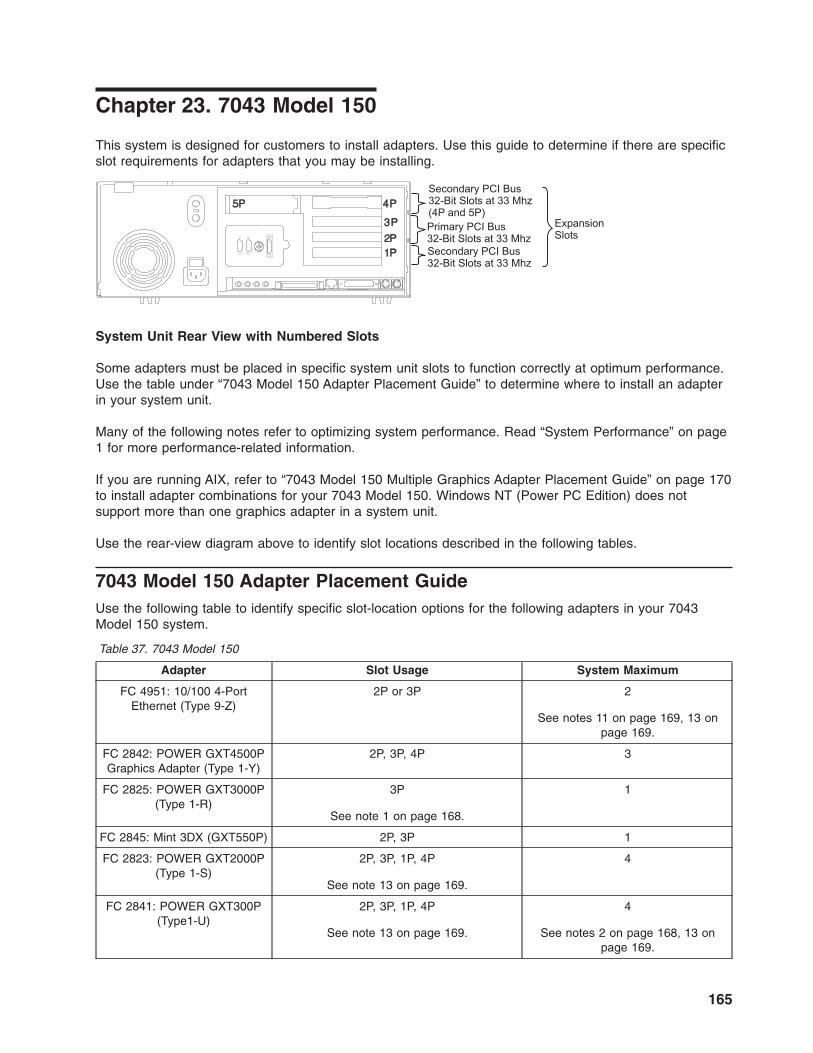
Chapter 23. 7043 Model 150
This system is designed for customers to install adapters. Use this guide to determine if there are specific
slot requirements for adapters that you may be installing.
Secondary PCI Bus32-Bit Slots at 33 Mhz(4P and 5P)
Secondary PCI Bus32-Bit Slots at 33 Mhz
ExpansionSlots
Primary PCI Bus32-Bit Slots at 33 Mhz
System Unit Rear View with Numbered Slots
Some adapters must be placed in specific system unit slots to function correctly at optimum performance.
Use the table under “7043 Model 150 Adapter Placement Guide” to determine where to install an adapter
in your system unit.
Many of the following notes refer to optimizing system performance. Read “System Performance” on page
1 for more performance-related information.
If you are running AIX, refer to “7043 Model 150 Multiple Graphics Adapter Placement Guide” on page 170
to install adapter combinations for your 7043 Model 150. Windows NT (Power PC Edition) does not
support more than one graphics adapter in a system unit.
Use the rear-view diagram above to identify slot locations described in the following tables.
7043 Model 150 Adapter Placement Guide
Use the following table to identify specific slot-location options for the following adapters in your 7043
Model 150 system.
Table 37. 7043 Model 150
Adapter Slot Usage System Maximum
FC 4951: 10/100 4-Port
Ethernet (Type 9-Z)
2P or 3P 2
See notes 11 on page 169, 13 on
page 169.
FC 2842: POWER GXT4500P
Graphics Adapter (Type 1-Y)
2P, 3P, 4P 3
FC 2825: POWER GXT3000P
(Type 1-R)
3P
See note 1 on page 168.
1
FC 2845: Mint 3DX (GXT550P) 2P, 3P 1
FC 2823: POWER GXT2000P
(Type 1-S)
2P, 3P, 1P, 4P
See note 13 on page 169.
4
FC 2841: POWER GXT300P
(Type1-U)
2P, 3P, 1P, 4P
See note 13 on page 169.
4
See notes 2 on page 168, 13 on
page 169.
165

Table 37. 7043 Model 150 (continued)
Adapter Slot Usage System Maximum
FC 2830: POWER GXT130P
(Type 1-T)
2P, 3P, 1P, 4P, 5P
See notes 2 on page 168, 7 on page 168
and 8 on page 169.
4
FC 2848: GXT135P Graphics
Adapter, 32-bit, 3.3/5V (Type
1-X)
2P, 3P, 1P, 4P, 5P 4
FC 2849: POWER GXT135P
Graphics Accelerator, 32-bit,
3.3/5V (Type 2849)
2P, 3P, 1P, 4P, 5P 4
FC 2852: POWER GXT255P
(Type 1-N)
See note 2 on page 168.
2P, 3P, 1P, 4P, 5P
See note 13 on page 169.
4
FC 2851: POWER GXT250P
(Type 1-M)
2P, 3P, 1P, 4P, 5P
See note 13 on page 169.
4
FC 2838: POWER GXT120P
(Type 1-P)
2P, 3P, 1P, 4P, 5P
See notes 2 on page 168, 7 on page 168
and 8 on page 169.
4
FC 2639: Ultimedia Video
Capture (Type 7-9)
1P, 2P, 3P, 4P, 5P
See note 10 on page 169 and 15 on page
169.
1
FC 4958: Cryptographic
Coprocessor (Type 6-H)
3P, 4P 2
See note 16 on page 169.
FC 6205: PCI Dual Channel
Ultra2 SCSI (Type 4-R)
2P, 3P, 4P, 5P
See notes 7 on page 168, 8 on page 169,
and 14 on page 169.
2
FC 6203: Dual-Channel Ultra3
SCSI, 32/64-bit, 3.3/5V (Type
4-Y)
2P, 3P, 4P, 5P
See notes 7 on page 168 and 8 on page
169.
2
FC 6206: Single-Ended Ultra
SCSI Adapter, 32-bit, 5V (Type
4-K)
5P, 4P, 3P, 2P, 1P
See note 14 on page 169.
2
FC 6207: PCI Differential Ultra
SCSI (Type 4-L)
1P, 2P, 3P, 4P, 5P 2
FC 2494: PCI 3-Channel Ultra2
SCSI RAID (Type 4-T)
2P, 3P
See notes 10 on page 169 and 15 on page
169.
2
FC 6225: Advanced SSA
SerialRAID (Type 4-P)
2P, 3P 1
See note 6 on page 168.
166 Adapter Placement Reference for AIX

Table 37. 7043 Model 150 (continued)
Adapter Slot Usage System Maximum
FC 6230: Advanced SerialRAID
Plus, 32-bit, 3.3/5V (Type 4-P)
FC 6230+6231: 4 Port SSA 40
w/128MB DIMM
FC 6235: Fast Write Cache
Option for FC 6225 and FC
6230
2P, 3P 1
See note 6 on page 168.
FC 6215: PCI SSA
Multi-Initiator/RAID EL (Type
4-N)
2P, 3P 1
See note 6 on page 168.
FC 2498: PCI 4-Channel Ultra3
SCSI RAID, 32/64-bit, 3.3/5V
(Type 4-X)
2P, 3P 2
FC 6310: IBM ARTIC960 RxD
Quad Digital Trunk PCI, 32-bit,
3.3/5V (Type 6-E)
4P, 3P, 2P
(see Chapter 35, “Digital Trunk PCI Adapter
Placement Considerations,” on page 225,
and note 9 on page 169.
3
FC 6311: IBM ARTIC960 RxF
PCI, 32-bit, 3.3/5V (Type 6-G)
4P, 3P, 2P
(see Chapter 35, “Digital Trunk PCI Adapter
Placement Considerations,” on page 225,
and note 9 on page 169.
2
FC 2947: IBM ARTIC960Hx
4-Port Selectable PCI, 32-bit,
3.3/5V (Type 9-R)
4P, 3P, 2P 3
FC 2948: IBM ARTIC960
4-Port T1/E1 PCI (Type 9-S)
4P, 3P, 2P 3
FC 4959: High-Speed Token
Ring PCI, 32-bit, 3.3/5V (Type
9-Y)
1P, 2P, 3P, 4P, 5P 4
FC 2920: 16Mbps PCI
Token-Ring (Type 9-0)
1P, 2P, 3P, 4P, 5P 4
FC 2968: 10/100 Mbps
Ethernet Tx PCI (Type 9-P )
2P, 3P, 1P, 4P, 5P 4
See note 4 on page 168.
FC 4962: Ethernet/LAN
Encryption 10/100BaseT,
32-bit, 3.3/5V (Type A-F)
2P, 3P, 1P, 4P, 5P 4
See note 4 on page 168.
FC 2943: 8-Port Asynchronous
EIA-232E/RS-422A PCI, 32-bit,
3.3/5V (Type 3-B)
1P, 2P, 3P, 4P, 5P 2
FC 2944: 128-Port Async
Controller PCI, 32-bit, 3.3/5V
(Type 3-C)
1P, 2P, 3P, 4P, 5P 2
FC 2962: 2-Port Multiprotocol
PCII, 32-bit, 3.3/5V (Type 9-V)
5P, 4P, 1P 2
FC 2963: TURBOWAYS 155
PCI UTP ATM (Type 9-J)
1P, 2P, 3P, 4P, 5P 2
See note 5 on page 168.
Chapter 23. 7043 Model 150 167

Table 37. 7043 Model 150 (continued)
Adapter Slot Usage System Maximum
FC 4953: 64-bit/66MHz PCI
ATM 155 UTP, 3.3/5V (Type
A-C)
1P, 2P, 3P, 4P, 5P 2
See note 5.
FC 2988: TURBOWAYS 155
PCI MMF ATM (Type 9-F)
1P, 2P, 3P, 4P, 5P 2
See note 5.
FC 4957: 64-bit/66MHz PCI
ATM 155 MMF, 3.3/5V (Type
A-D)
1P, 2P, 3P, 4P, 5P 2
See note 5.
FC 2708: ISDN Basic Rate PCI
(Type 9-N)
2P, 3P 1
FC 2998: TURBOWAYS 25
ATM PCI (Type *)
1P, 2P, 3P, 4P, 5P 4
FC 2742: SysKonnect SK-NET
FDDI-LP DAS PCI, 32-bit,
3.3/5V No type label.
1P, 2P, 3P, 4P, 5P
See note 3.
2
FC 2741: SysKonnect SK-NET
FDDI-LP SAS PCI, 32-bit,
3.3/5V No type label.
1P, 2P, 3P, 4P, 5P
See note 3.
2
FC 2743: SysKonnect SK-NET
FDDI-UP SAS PCI (Type *)
1P, 2P, 3P, 4P, 5P
See note 3.
2
FC 4960: IBM Cryptographic
Accelerator, 32-bit, 3.3/5V
(Type 6-J)
1P, 2P, 3P, 4P, 5P 4
Notes:
1. The FC 2825: POWER GXT3000P (Type 1-R) occupies the physical space of two adapters in the
7043 Model 150, and, if installed, will fill slots 1 and 2.
2. If both the FC 2838: POWER GXT120P (Type 1-P) or FC 2830: POWER GXT130P (Type 1-T) and
the FC 2852: POWER GXT255P (Type 1-N) or FC 2841: POWER GXT300P (Type1-U) are installed,
the FC 2852: POWER GXT255P (Type 1-N) or FC 2841: POWER GXT300P (Type1-U) must be
installed in slot 2 or 3.
3. If two SysKonnect SK-NET FDDI PCI adapters are installed, they cannot be installed in slots next to
each other.
4. For optimum system performance, place FC 2968: 10/100 Mbps Ethernet Tx PCI (Type 9-P ) or FC
4962: Ethernet/LAN Encryption 10/100BaseT, 32-bit, 3.3/5V (Type A-F) in slots 2 and 3, with no more
than 2 per system. You may have a total of 5 per system for connectivity, including integrated
ethernet.
5. For optimum system performance, when using a FC 2988: TURBOWAYS 155 PCI MMF ATM (Type
9-F), FC 2963: TURBOWAYS 155 PCI UTP ATM (Type 9-J), FC 4953: 64-bit/66MHz PCI ATM 155
UTP, 3.3/5V (Type A-C), or FC 4957: 64-bit/66MHz PCI ATM 155 MMF, 3.3/5V (Type A-D) adapter in
LAN Emulation (LANE) a maximum of one adapter per system is recommended.
6. Install only one of the following adapters:
v FC 6215: PCI SSA Multi-Initiator/RAID EL (Type 4-N)
v FC 6225: Advanced SSA SerialRAID (Type 4-P)
v FC 6230: Advanced SerialRAID Plus, 32-bit, 3.3/5V (Type 4-P)
7. Do not install an FC 6205: PCI Dual Channel Ultra2 SCSI (Type 4-R) or FC 6203: Dual-Channel
Ultra3 SCSI, 32/64-bit, 3.3/5V (Type 4-Y) adapter on the same PCI bus as a FC 2838: POWER
GXT120P (Type 1-P)or older versions of the FC 2830: POWER GXT130P (Type 1-T). To determine if
168 Adapter Placement Reference for AIX

you have an older version of the FC 2830: POWER GXT130P (Type 1-T), remove the card and
examine the bar code label on the back side. If it has a number starting with 11S94H1235, you have
an older version of the card.
8. If the FC 6205: PCI Dual Channel Ultra2 SCSI (Type 4-R) or FC 6203: Dual-Channel Ultra3 SCSI,
32/64-bit, 3.3/5V (Type 4-Y) adapter is plugged into slot 2 or 3, then the POWER GXT120P or the
POWER GXT130P can only be plugged in slots 1, 4, or 5. If you plug the POWER GXT120P or the
POWER GXT130P in slots 2 or 3, then you must plug the Ultra2 SCSI adapter in slots 1, 4 or 5.
9. Do not install more than a combination of three FC 6311: IBM ARTIC960 RxF PCI, 32-bit, 3.3/5V
(Type 6-G) and FC 6310: IBM ARTIC960 RxD Quad Digital Trunk PCI, 32-bit, 3.3/5V (Type 6-E)
adapters in this system.
10. Do not install an FC 2494: PCI 3-Channel Ultra2 SCSI RAID (Type 4-T) and a FC 6311: IBM
ARTIC960 RxF PCI, 32-bit, 3.3/5V (Type 6-G) adapter on the same bus.
11. For optimum system performance, use only two 100 Mbs ports per system.
12. Do not install the FC 6205: PCI Dual Channel Ultra2 SCSI (Type 4-R) adapter in slots 2 or 3 if you
also have a FC 2823: POWER GXT2000P (Type 1-S) installed on this system.
13. When FC 4951: 10/100 4-Port Ethernet (Type 9-Z) is installed, the following adapters must be
installed in slots 1, 4, or 5: FC 2823, FC 2841, FC 2851, and FC 2852.
14. FC 2445 is the internal SCSI cable used with FC 6206: Single-Ended Ultra SCSI Adapter, 32-bit, 5V
(Type 4-K), or with FC 6205: PCI Dual Channel Ultra2 SCSI (Type 4-R). The SCSI adapter card (FC
6206 or FC 6205), which is to be connected to the internal drives using FC 2445, must be installed in
Slot 5. If FC 2445 and either FC 6206 or FC 6205 are on the order, slot location placement for FC
6206 and FC 6205 is slot 5 first priority.
15. FC 2494: PCI 3-Channel Ultra2 SCSI RAID (Type 4-T) and FC 2639: Ultimedia Video Capture (Type
7-9) adapters cannot be installed together.
16. Any combination of the following adapters may be installed, but the combined total should not exceed
two per system: FC 4958: Cryptographic Coprocessor (Type 6-H) and FC 4963: Cryptographic
Coprocessor, FIPS-4, 32-bit, 3.3/5V (Type 6-I), also referred to as RPQ 8A1162: Cryptographic
Coprocessor.
17. For optimum system performance, the combined maximum of high-performance adapters should not
exceed the maximums listed for FC 5706: 2-Port 10/100/1000 Base-TX Ethernet PCI-X, 32/64-bit,
3.3/5V (Type 5706) or FC 5707: 2-Port Gigabit Ethernet-SX PCI-X, 32/64-bit, 3.3/5V (Type 5707) if
either of these adapters is installed in the system. For a list of high-performance adapters, see
Appendix B, “High-Performance Adapters,” on page 233.
Chapter 23. 7043 Model 150 169

7043 Model 150 Multiple Graphics Adapter Placement Guide
Use the following table to identify adapter location combination options for these adapters in your 7043
Model 150.
Do not install more than four graphics adapters in your 7043 Model 150.
Table 38. 7043 Model 150
Adapter Slot
FC 2838: POWER GXT120P (Type 1-P) or FC 2830:
POWER GXT130P (Type 1-T) or FC 2851: POWER
GXT250P (Type 1-M) or FC 2852: POWER GXT255P
(Type 1-N) or FC 2823: POWER GXT2000P (Type
1-S) or FC 2841: POWER GXT300P (Type1-U) or FC
2848: GXT135P Graphics Adapter, 32-bit, 3.3/5V
(Type 1-X) or FC 2842: POWER GXT4500P Graphics
Adapter (Type 1-Y)
1P - 5P
with a
FC 2838: POWER GXT120P (Type 1-P) or FC 2830:
POWER GXT130P (Type 1-T) or FC 2851: POWER
GXT250P (Type 1-M) or FC 2852: POWER GXT255P
(Type 1-N) or FC 2823: POWER GXT2000P (Type
1-S) or FC 2841: POWER GXT300P (Type1-U) or FC
2848: GXT135P Graphics Adapter, 32-bit, 3.3/5V
(Type 1-X) or FC 2842: POWER GXT4500P Graphics
Adapter (Type 1-Y)
1P - 5P
FC 2838: POWER GXT120P (Type 1-P) or FC 2830:
POWER GXT130P (Type 1-T) or FC 2851: POWER
GXT250P (Type 1-M) or FC 2852: POWER GXT255P
(Type 1-N) or FC 2823: POWER GXT2000P (Type
1-S) or FC 2841: POWER GXT300P (Type1-U) or FC
2848: GXT135P Graphics Adapter, 32-bit, 3.3/5V
(Type 1-X) or FC 2842: POWER GXT4500P Graphics
Adapter (Type 1-Y)
1P
with a
FC 2855: POWER GXT550P (Type 1-J) 2P or 3P
FC 2838: POWER GXT120P (Type 1-P) or FC 2830:
POWER GXT130P (Type 1-T) or FC 2851: POWER
GXT250P (Type 1-M) or FC 2852: POWER GXT255P
(Type 1-N) or FC 2823: POWER GXT2000P (Type
1-S) or FC 2841: POWER GXT300P (Type1-U) or FC
2848: GXT135P Graphics Adapter, 32-bit, 3.3/5V
(Type 1-X) or FC 2842: POWER GXT4500P Graphics
Adapter (Type 1-Y)
1P or 4P or 5P
with a
FC 2825: POWER GXT3000P (Type 1-R) 3P
FC 2639: Ultimedia Video Capture (Type 7-9) 1P or 4P or 5P
with a
FC 2825: POWER GXT3000P (Type 1-R) 3P
FC 2639: Ultimedia Video Capture (Type 7-9) 1P - 5P
with a
FC 2823: POWER GXT2000P (Type 1-S) 1P - 5P
FC 2639: Ultimedia Video Capture (Type 7-9) 1P - 5P
170 Adapter Placement Reference for AIX

Table 38. 7043 Model 150 (continued)
Adapter Slot
with a
FC 2841: POWER GXT300P (Type1-U) 1P - 5P
Notes:
1. The FC 2825: POWER GXT3000P (Type 1-R) occupies the physical space of two adapters in the 7043
Model 150.
Chapter 23. 7043 Model 150 171

172 Adapter Placement Reference for AIX

Chapter 24. 7043 Model 240
This system is designed for customers to install adapters. Use this guide to determine if there are specific
slot requirements for adapters that you may be installing.
5I 4I
2P1P
3P
1P, 32-Bit Slot
3P, 32-Bit Slot2P, 64-Bit Slot
ExpansionSlotsPrimary
PCI Bus,
ISA Slots (4I and 5I)
System Unit Rear View with Numbered Slots
Note: In the figure above, slots 1P and 3P are on a primary PCI bus running at 33 MHz. Slot 2P is on a
separate primary PCI bus running at 50/33 MHz.
Some adapters must be placed in specific system unit slots to function correctly and to achieve optimum
performance. Use the table under “7043 Model 240 Adapter Placement Guide” to determine where to
install an adapter in your system unit.
Many of the following notes refer to optimizing system performance. Read “System Performance” on page
1 for more performance-related information.
If you are running AIX, refer to “7043 Model 240 Multiple Graphics Adapter Placement Guide” on page 176
to install adapter combinations for your 7043 Model 240. Windows NT (PowerPC Edition) does not support
more than one graphics adapter in a system unit.
Use the rear-view diagram above to identify slot locations described in the following tables.
7043 Model 240 Adapter Placement Guide
Use the following table to identify slot-location options for the following adapters in your 7043 Model 240.
Table 39. 7043 Model 240
Adapter AIX Windows NT
FC 6309: Digital Trunk Quad PCI (Type 6-B) Slot 2P, Slot 3P
Max. 2 per system
FC 2839: POWER GXT110P (Type *) Slot 1P, Slot 3P Slot 1P, Slot 3P
FC 2838: POWER GXT120P (Type 1-P) Slot 1P - 3P
FC 2851: POWER GXT250P (Type 1-M)
or
FC 2852: POWER GXT255P (Type 1-N)
Slots 1P - 3P (2P Best) Slots 1P - 3P
FC 2854: POWER GXT500P (Type 1-I)
or
FC 2855: POWER GXT550P (Type 1-J)
Slot 2P
See note 4 on page 175.
173

Table 39. 7043 Model 240 (continued)
Adapter AIX Windows NT
FC 2853: POWER GXT800P (Type 1-K) Slot 2P
See note 3 on page 175.
FC 2856: POWER GXT1000 (Type 1-H) Slots 1P - 3P (2P Best)
FC 2920: 16Mbps PCI Token-Ring (Type 9-0) Slot 1P, Slot 2P, Slot 3P
Max. 2 per system
FC 2979: PCI Auto LANstreamer Token Ring
(Type 8-T)
Slot 1P, Slot 2P, Slot 3P
Max. 2 per system
FC 6215: PCI SSA Multi-Initiator/RAID EL (Type
4-N)
Slots 2P - 3P
FC 6218: PCI SSA 4-Port RAID (Type 4-J) Slots 2P - 3P
FC 2639: Ultimedia Video Capture (Type 7-9) Slots 1P, 2P, or 3P
Max. 1 per system
FC 2988: TURBOWAYS 155 PCI MMF ATM
(Type 9-F)
See note 2.
FC 2963: TURBOWAYS 155 PCI UTP ATM
(Type 9-J)
See note 2.
FC 2986: 10/100 Mbps PCI Fast Etherlink XL
(Type *)
See note 2.
FC 2968: 10/100 Mbps Ethernet Tx PCI (Type
9-P )
See note 2.
FC 2493: PCI SCSI-2 Fast/Wide RAID (Type
4-H)
See note 2.
FC 2742: SysKonnect SK-NET FDDI-LP DAS
PCI, 32-bit, 3.3/5V No type label.
See note 2.
FC 2741: SysKonnect SK-NET FDDI-LP SAS
PCI, 32-bit, 3.3/5V No type label.
See note 2.
FC 2743: SysKonnect SK-NET FDDI-UP SAS
PCI (Type *)
See note 2.
Notes:
1. ″Best″ means optimum performance achieved if installed in this slot.
2. Connectivity Note: The 7043 Model 240 supports any combination of the following adapters, but that
combination cannot exceed a total of two:
v FC 2988: TURBOWAYS 155 PCI MMF ATM (Type 9-F)
v FC 2963: TURBOWAYS 155 PCI UTP ATM (Type 9-J)
v FC 2986: 10/100 Mbps PCI Fast Etherlink XL (Type *)
v FC 2968: 10/100 Mbps Ethernet Tx PCI (Type 9-P )
v FC 2493: PCI SCSI-2 Fast/Wide RAID (Type 4-H)
v FC 2742: SysKonnect SK-NET FDDI-LP DAS PCI, 32-bit, 3.3/5V No type label.
v FC 2741: SysKonnect SK-NET FDDI-LP SAS PCI, 32-bit, 3.3/5V No type label.
v FC 2743: SysKonnect SK-NET FDDI-UP SAS PCI (Type *)
Performance Notes: For optimum system performance, a maximum of one of the following adapters
is recommended. (This restriction does not apply if the FC 2968: 10/100 Mbps Ethernet Tx PCI (Type
9-P ) adapter is used in 10 Mbps mode.)
v FC 2988: TURBOWAYS 155 PCI MMF ATM (Type 9-F)
174 Adapter Placement Reference for AIX

v FC 2963: TURBOWAYS 155 PCI UTP ATM (Type 9-J)
v FC 2986: 10/100 Mbps PCI Fast Etherlink XL (Type *)
v FC 2968: 10/100 Mbps Ethernet Tx PCI (Type 9-P )
v FC 2493: PCI SCSI-2 Fast/Wide RAID (Type 4-H)
v FC 2742: SysKonnect SK-NET FDDI-LP DAS PCI, 32-bit, 3.3/5V No type label.
v FC 2741: SysKonnect SK-NET FDDI-LP SAS PCI, 32-bit, 3.3/5V No type label.
v FC 2743: SysKonnect SK-NET FDDI-UP SAS PCI (Type *)
3. The FC 2853: POWER GXT800P (Type 1-K) occupies the physical space of three adapters in the
7043 Model 240.
4. When installing a FC 2855: POWER GXT550P (Type 1-J)in the 7043 Model 240, an electrical
grounding tab is installed on the front of the adapter to allow connection to the 7043 Model 240 frame.
Follow the instructions that are supplied with the adapter to attach the grounding tab.
Chapter 24. 7043 Model 240 175

7043 Model 240 Multiple Graphics Adapter Placement Guide
Use the following table to identify slot location combination options for the following adapters in your 7043
Model 240.
Do not install more than four graphics adapters in your 7043 Model 240.
Table 40. 7043 Model 240
Adapter Slot
FC 2839: POWER GXT110P (Type *) Slot 1P Slot 3P
with a OR
FC 2838: POWER GXT120P (Type 1-P) or FC 2851:
POWER GXT250P (Type 1-M) or FC 2852: POWER
GXT255P (Type 1-N)
Slot 2P Best or 3P Slots 2P Best or 1P
FC 2839: POWER GXT110P (Type *) Slot 1P, Slot 3P
with a
FC 2854: POWER GXT500P (Type 1-I) or FC 2855:
POWER GXT550P (Type 1-J)
Slot 2P
FC 2839: POWER GXT110P (Type *) Slot 1P
with a
FC 2853: POWER GXT800P (Type 1-K) Slot 2P
FC 2839: POWER GXT110P (Type *) Slot 1P Slot 3P
with a OR
FC 2856: POWER GXT1000 (Type 1-H) Slot 2P Best or 3P Slots 2P Best or 1P
176 Adapter Placement Reference for AIX

Table 41. 7043 Model 240
Adapter Slot
FC 2838: POWER GXT120P (Type 1-P) or FC 2851:
POWER GXT250P (Type 1-M) or FC 2852: POWER
GXT255P (Type 1-N)
Slots 1P - 3P
with a
FC 2838: POWER GXT120P (Type 1-P) or FC 2851:
POWER GXT250P (Type 1-M) or FC 2852: POWER
GXT255P (Type 1-N)
Slots 1P - 3P (Slot 2P Best)
FC 2838: POWER GXT120P (Type 1-P) or FC 2851:
POWER GXT250P (Type 1-M) or FC 2852: POWER
GXT255P (Type 1-N)
Slot 1P, Slot 3P
with a
FC 2854: POWER GXT500P (Type 1-I) or FC 2855:
POWER GXT550P (Type 1-J)
Slot 2P
FC 2838: POWER GXT120P (Type 1-P) or FC 2851:
POWER GXT250P (Type 1-M) or FC 2852: POWER
GXT255P (Type 1-N)
Slot 1P
with a
FC 2853: POWER GXT800P (Type 1-K) Slot 2P
FC 2838: POWER GXT120P (Type 1-P) or FC 2851:
POWER GXT250P (Type 1-M) or FC 2852: POWER
GXT255P (Type 1-N)
Slot 2P Best Slot 1P Slot 3P
with a OR OR
FC 2856: POWER GXT1000 (Type 1-H) Slots 1P or 3P
Slot 2P Best or 3P
Slot 2P Best or 1P
FC 2838: POWER GXT120P (Type 1-P) or FC 2851:
POWER GXT250P (Type 1-M) or FC 2852: POWER
GXT255P (Type 1-N)
Slot 2P Best Slot 1P Slot 3P
with a OR OR
FC 2962: 2-Port Multiprotocol PCII, 32-bit, 3.3/5V
(Type 9-V)
Slots 1P or 3P Slot 2P Slot 2P
FC 2639: Ultimedia Video Capture (Type 7-9) Slot 1P
with a
FC 2853: POWER GXT800P (Type 1-K) Slot 2P
Notes:
1. ″Best″ means optimum performance achieved if installed in this slot.
Chapter 24. 7043 Model 240 177

178 Adapter Placement Reference for AIX

Chapter 25. 7043 Model 260
This system is designed for customers to install adapters. Use this guide to determine if there are specific
slot requirements for adapters that you may be installing.
1
2345 Secondary PCI Bus,
32-Bit Slots at 33 MHzExpansionSlotsPrimary PCI Bus,
64-Bit Slots at 50/33 MHz
System Unit Rear View with Numbered Slots
Some adapters must be placed in specific system unit slots to function correctly at optimum performance.
Use the table under “7043 Model 260 Adapter Placement Guide” to determine where to install an adapter
in your system unit.
Many of the following notes refer to optimizing system performance. Read “System Performance” on page
1 for more performance-related information.
Use the rear-view diagram above to identify slot locations described in the following tables.
7043 Model 260 Adapter Placement Guide
Use the following table to identify specific slot location options for the following adapters in your 7043
Model 260 system.
If two different adapters can be placed in the same slot, the highest priority adapter starts at the top of the
table. The list of slot numbers represents the order that the slots should be used.
Table 42. 7043 Model 260
Adapter Slot Usage Max. per System
FC 2825: POWER GXT3000P (Type 1-R) Slot 2, 4See note 12 on page 182.
2
FC 2823: POWER GXT2000P (Type 1-S) Any slot 4
FC 2851: 3MB (GXT250P) 64-BIT, 3.3 or 5V,
Graphics Adapter (Type 1-M)
Any slot 4
FC 2852: 3MB (GXT255P) 64-BIT, 3.3 or 5V,
Graphics Adapter (Type 1-N)
Any slot 4
FC 2841: POWER GXT300P (Type1-U) Any slot 4
179

Table 42. 7043 Model 260 (continued)
Adapter Slot Usage Max. per System
FC 2838: POWER GXT120P (Type 1-P) Any slotSee note 6 on page 182.
4
FC 2830: POWER GXT130P (Type 1-T) Any slotSee note 6 on page 182.
4
FC 2975: Gigabit Ethernet (UTP) 1000BaseT,
64-bit, 3.3/5V (Type A-A)
Slot 1, 2 2See notes 9 on page 182 and 2
on page 181.
FC 2969: Gigabit Ethernet Fibre, 1000BaseT,
64-bit, 3.3/5V (Type 9-U)
Slot 1, 2 2See note 2 on page 181.
FC 6310: IBM ARTIC960 RxD Quad Digital
Trunk PCI, 32-bit, 3.3/5V (Type 6-E)
Slots 3, 4, 5See Chapter 35, “Digital Trunk
PCI Adapter Placement
Considerations,” on page 225
and note 7 on page 182.
1
FC 6311: IBM ARTIC960 RxF PCI, 32-bit,
3.3/5V (Type 6-G)
Slots 3, 4, 5See Chapter 35, “Digital Trunk
PCI Adapter Placement
Considerations,” on page 225
and note 7 on page 182.
3
FC 2494: PCI 3-Channel Ultra2 SCSI RAID
(Type 4-T)
Any slotSee note 8 on page 182.
2
FC 2708: ISDN Basic Rate PCI (Type 9-N) Any slot 1
FC 6227: Gigabit Fibre Channel PCI (Type
4-S)
Slots 5, 4, 3, 2, 1 1
FC 2639: Ultimedia Video Capture (Type 7-9) Any slotSee note 8 on page 182.
1
FC 6215: PCI SSA Multi-Initiator/RAID EL
(Type 4-N)
Any slot 2
FC 6222: 4-Port, SSA-RAID1 Fast Write Cache
Option (Type 4-N)
N/ASee note 13 on page 182.
1
FC 6230: Advanced SerialRAID Plus, 32-bit,
3.3/5V (Type 4-P)
FC 6230+6231: 4 Port SSA 40 w/128MB DIMM
FC 6235: Fast Write Cache Option for FC 6225
and FC 6230
Any slot 2See notes 4 on page 181 and 14
on page 182.
FC 6225: Advanced SSA SerialRAID (Type
4-P)
Any slot 2See note 4 on page 181.
FC 6231: 128 MByte DRAM Option Card for
FC 6225 and FC 6230
N/A 1
FC 2947: IBM ARTIC960Hx 4-Port Selectable
PCI, 32-bit, 3.3/5V (Type 9-R)
Any slot 2
FC 2948: IBM ARTIC960 4-Port T1/E1 PCI
(Type 9-S)
Any slot 2
FC 2943: 8-Port Asynchronous
EIA-232E/RS-422A PCI, 32-bit, 3.3/5V (Type
3-B)
Any slot 2
FC 2944: 128-Port Async Controller PCI,
32-bit, 3.3/5V (Type 3-C)
Any slot 2
180 Adapter Placement Reference for AIX

Table 42. 7043 Model 260 (continued)
Adapter Slot Usage Max. per System
FC 2962: 2-Port Multiprotocol PCII, 32-bit,
3.3/5V (Type 9-V)
Any slot 2
FC 2946: PCI TURBOWAYS 622 PCI MMF
ATM, 64-bit, 3.3/5V (Type A-B)
1, 2, 3, 4, 5 5See note 2.
FC 2963: TURBOWAYS 155 PCI UTP ATM
(Type 9-J)
Any slot 2See notes 3 and 10 on page
182.
FC 2988: TURBOWAYS 155 PCI MMF ATM
(Type 9-F)
Any slot 2See note 3.
FC 2742: SysKonnect SK-NET FDDI-LP DAS
PCI, 32-bit, 3.3/5V No type label.
Any slot 2
FC 2741: SysKonnect SK-NET FDDI-LP SAS
PCI, 32-bit, 3.3/5V No type label.
Any slot 2
FC 2743: SysKonnect SK-NET FDDI-UP SAS
PCI (Type *)
Any slot 2
FC 6205: PCI Dual Channel Ultra2 SCSI (Type
4-R)
Any slotSee notes 5 on page 182 and 6
on page 182.
2
FC 2498: PCI 4-Channel Ultra3 SCSI RAID,
32/64-bit, 3.3/5V (Type 4-X)
Any slot 2
FC 4959: High-Speed Token Ring PCI, 32-bit,
3.3/5V (Type 9-Y)
5, 4, 3, 2, 1 3
FC 2920: 16Mbps PCI Token-Ring (Type 9-0) Any slot 4
FC 6206: Single-Ended Ultra SCSI Adapter,
32-bit, 5V (Type 4-K)
Any slot 4
FC 6207: PCI Differential Ultra SCSI (Type 4-L) Any slot 4
FC 2968: 10/100 Mbps Ethernet Tx PCI (Type
9-P )
Any slot 4See note 1.
FC 2998: TURBOWAYS 25 ATM PCI (Type *) Any slot 4
FC 4951: 10/100 4-Port Ethernet (Type 9-Z) 5, 4, 3, 2, 1 5See note 11 on page 182.
FC 2851: POWER GXT250P (Type 1-M) Any slot 4
FC 2852: POWER GXT255P (Type 1-N) Any slot 4
Notes:
1. For optimum system performance, if the FC 2968: 10/100 Mbps Ethernet Tx PCI (Type 9-P ) is used
in 100 Mbps mode then a maximum of three adapters is recommended per system unit.
2. For optimum system performance, a maximum of one of the following adapters is recommended per
system:
v FC 2969: Gigabit Ethernet Fibre, 1000BaseT, 64-bit, 3.3/5V (Type 9-U)
v FC 2975: Gigabit Ethernet (UTP) 1000BaseT, 64-bit, 3.3/5V (Type A-A)
v FC 2946: PCI TURBOWAYS 622 PCI MMF ATM, 64-bit, 3.3/5V (Type A-B)
3. When in LAN emulation mode, install a maximum of three 155 TURBOWAYS ATM PCI MMFs for
optimum system performance.
4. You may install any combination of FC 6225: Advanced SSA SerialRAID (Type 4-P) and FC 6230:
Advanced SerialRAID Plus, 32-bit, 3.3/5V (Type 4-P) adapters, as long as that combination does not
exceed two per system unit.
Chapter 25. 7043 Model 260 181

5. For optimum system performance, put the FC 6205: PCI Dual Channel Ultra2 SCSI (Type 4-R)
adapters in slots 1-2.
6. Do not install a FC 6205: PCI Dual Channel Ultra2 SCSI (Type 4-R) Adapter in the same PCI bus as
a FC 2838: POWER GXT120P (Type 1-P) or a FC 2830: POWER GXT130P (Type 1-T).
7. Do not install more than a combination of four FC 6311: IBM ARTIC960 RxF PCI, 32-bit, 3.3/5V (Type
6-G)s and FC 6310: IBM ARTIC960 RxD Quad Digital Trunk PCI, 32-bit, 3.3/5V (Type 6-E)s in this
system.
8. The FC 2639: Ultimedia Video Capture (Type 7-9) adapter may not occupy the same PCI bus as the
FC 2494: PCI 3-Channel Ultra2 SCSI RAID (Type 4-T) adapters.
9. Install a maximum of one FC 2975: Gigabit Ethernet (UTP) 1000BaseT, 64-bit, 3.3/5V (Type A-A)
adapter per system (if configured to run at 1000 Mbps) for optimum performance. If you have
configured the adapter to run at 100 Mbps, use up to three for optimum performance.
10. Install a maximum of one FC 2963: TURBOWAYS 155 PCI UTP ATM (Type 9-J) adapter per system
for optimum system performance.
11. Install a maximum of one FC 4951: 10/100 4-Port Ethernet (Type 9-Z) adapters configured to run at
100 Mbps mode per system for optimum performance.
12. If two FC 2825: POWER GXT3000P (Type 1-R) adapters are placed in slots 2 and 4, then slot 3 is
covered and cannot be used.
13. FC 6222: 4-Port, SSA-RAID1 Fast Write Cache Option (Type 4-N) is a cache upgrade for the
Campbell RAID adapter and can only be selected along with FC 6215: PCI SSA Multi-Initiator/RAID
EL (Type 4-N) (maximum 1 per 6215).
14. FC 6235: Fast Write Cache Option for FC 6225 and FC 6230 is a cache upgrade for the FC 6225:
Advanced SSA SerialRAID (Type 4-P) adapter and can only be selected along with FC 6225 or FC
6230: Advanced SerialRAID Plus, 32-bit, 3.3/5V (Type 4-P) (maximum 1 per 6225/6230).
182 Adapter Placement Reference for AIX

7043 Model 260 Multiple Graphics Adapter Placement Guide
Use the following table to identify adapter location combination options for these adapters in your 7043
Model 260.
Do not install more than four graphics adapters in your 7043 Model 260.
Table 43. 7043 Model 260
Adapter AIX
FC 2838: POWER GXT120P (Type 1-P) or FC 2830: POWER GXT130P
(Type 1-T) or FC 2851: POWER GXT250P (Type 1-M) or FC 2852: POWER
GXT255P (Type 1-N) or FC 2823: POWER GXT2000P (Type 1-S) or FC
2841: POWER GXT300P (Type1-U)
Slot 1 - 5, See note
with a
FC 2838: POWER GXT120P (Type 1-P) or FC 2830: POWER GXT130P
(Type 1-T) or FC 2851: POWER GXT250P (Type 1-M) or FC 2852: POWER
GXT255P (Type 1-N) or FC 2823: POWER GXT2000P (Type 1-S) or FC
2841: POWER GXT300P (Type1-U)
Slot 1 - 5
FC 2838: POWER GXT120P (Type 1-P) or FC 2830: POWER GXT130P
(Type 1-T) or FC 2851: POWER GXT250P (Type 1-M) or FC 2852: POWER
GXT255P (Type 1-N) or FC 2823: POWER GXT2000P (Type 1-S) or FC
2841: POWER GXT300P (Type1-U)
Slots 1, 3, 4, 5, See note
with a
FC 2825: POWER GXT3000P (Type 1-R) Slot 2
FC 2639: Ultimedia Video Capture (Type 7-9) Slots 1, 3, 4, 5, See note
with a
FC 2825: POWER GXT3000P (Type 1-R) Slot 2
FC 2639: Ultimedia Video Capture (Type 7-9) Slot 1 - 5, See note
with a
FC 2823: POWER GXT2000P (Type 1-S) Slot 1 - 5
FC 2639: Ultimedia Video Capture (Type 7-9) Slot 1 - 5
with a
FC 2841: POWER GXT300P (Type1-U) Slot 1 - 5, See note
Note:
Since slots 1 and 2 are capable of running at 50 mhz, the GXT250P, GXT255P, GXT2000P, GXT 3000P
and FC 2841: POWER GXT300P (Type1-U) should be placed in these slots for optimum performance.
Take care when placing the GXT120P or FC 2830: POWER GXT130P (Type 1-T) (or any other 33 Mhz
PCI adapter) in slots 1 and 2, because this forces the slots to run at 33 Mhz.
Chapter 25. 7043 Model 260 183

184 Adapter Placement Reference for AIX

Chapter 26. 7044 Model 170
This system is designed for customers to install adapters. Use this guide to determine if there are specific
slot requirements for adapters that you may be installing.
PCI Slot 1
PCI Slot 2
PCI Slot 3
PCI Slot 4
PCI Slot 5
PCI Slot 6
Primary bus 64-bit slots at 50MHz
Secondary bus 32-bit slots at 33MHz
System Unit Rear View with Numbered Slots
Some adapters must be placed in specific system unit slots to function correctly at optimum performance.
Use the table under “7044 Model 170 Adapter Placement Guide” on page 186 to determine where to
install an adapter in your system unit.
Many of the following notes refer to optimizing system performance. Read “System Performance” on page
1 for more performance-related information.
Use the rear-view diagram above to identify slot locations described in the following tables.
185

7044 Model 170 Adapter Placement Guide
Use the following table to identify specific slot location options for the following adapters in your 7044
Model 170 system.
Table 44. 7044 Model 170
Adapter Slot Usage System Maximum
FC 2827: POWER GXT6000P (Type 1-W) 1, 2, 3, 4, 5, 6 2
FC 2843: POWER GXT6500P Graphics
Adapter (Type 1-Z)
1, 2, 3, 4, 5, 6 4
FC 2842: POWER GXT4500P Graphics
Adapter (Type 1-Y)
1, 2, 3, 4, 5, 6 2
FC 2825: POWER GXT3000P (Type 1-R) 2
See note 11 on page 189.
1
FC 2969: Gigabit Ethernet Fibre,
1000BaseT, 64-bit, 3.3/5V (Type 9-U)
1, 2, 3, 4, 5, 6 6See note 2 on page 188.
FC 2975: Gigabit Ethernet (UTP)
1000BaseT, 64-bit, 3.3/5V (Type A-A)
1, 2, 3, 4, 5, 6 6
See notes 2 on page 188
and 6 on page 189.
FC 5707: 2-Port Gigabit Ethernet-SX
PCI-X, 32/64-bit, 3.3/5V (Type 5707)
1, 2 2
FC 5706: 2-Port 10/100/1000 Base-TX
Ethernet PCI-X, 32/64-bit, 3.3/5V (Type
5706)
1, 2 2
FC 5700: Gigabit Ethernet, 1000 Base-SX,
32/64-bit, 3.3/5V
1, 2, 3, 4, 5, 6 6
FC 5701: 10/100/1000 Base-TX Ethernet,
32/64-bit, 3.3/5V
1, 2, 3, 4, 5, 6 6
FC 2826: POWER GXT4000P (Type 1-V) 1, 2, 3, 4, 5, 6 4
FC 2830: POWER GXT130P (Type 1-T) 6, 5, 4, 3 4
FC 2849: POWER GXT135P Graphics
Accelerator, 32-bit, 3.3/5V (Type 2849)
1, 2, 3, 4, 5, 6 4See note 17 on page 189.
FC 2848: GXT135P Graphics Adapter,
32-bit, 3.3/5V (Type 1-X)
1, 2, 3, 4, 5, 6 4See note 17 on page 189.
FC 2823: POWER GXT2000P (Type 1-S) 1, 2, 3, 4, 5, 6 4
FC 2841: POWER GXT300P (Type1-U) 1, 2, 3, 4, 5, 6 4
FC 2498: PCI 4-Channel Ultra3 SCSI
RAID, 32/64-bit, 3.3/5V (Type 4-X)
1, 2, 6, 5, 4, 3 4See note 10 on page 189.
FC 4958: Cryptographic Coprocessor
(Type 6-H)
1, 2 2See note 19 on page 189.
FC 4963: Cryptographic Coprocessor,
FIPS-4, 32-bit, 3.3/5V (Type 6-I)
1, 2 2See note 19 on page 189.
FC 2494: PCI 3-Channel Ultra2 SCSI
RAID (Type 4-T)
6, 5, 4, 3
See note 1 on page 188.
2
FC 2943: 8-Port Asynchronous
EIA-232E/RS-422A PCI, 32-bit, 3.3/5V
(Type 3-B)
6, 5, 4, 3 2
186 Adapter Placement Reference for AIX

Table 44. 7044 Model 170 (continued)
Adapter Slot Usage System Maximum
FC 2944: 128-Port Async Controller PCI,
32-bit, 3.3/5V (Type 3-C)
6, 5, 4, 3 2
FC 2962: 2-Port Multiprotocol PCII, 32-bit,
3.3/5V (Type 9-V)
6, 5, 4, 3 2
FC 6206: Single-Ended Ultra SCSI
Adapter, 32-bit, 5V (Type 4-K)
6, 5, 4, 3 4
FC 6203: Dual-Channel Ultra3 SCSI,
32/64-bit, 3.3/5V (Type 4-Y)
6, 5, 4, 3, 2, 1 4
FC 2639: Ultimedia Video Capture (Type
7-9)
6, 5, 4, 3
See note 1 on page 188.
1
FC 4951: 10/100 4-Port Ethernet (Type
9-Z)
6, 5, 4, 3 4
See note 13 on page 189.
FC 2985: Ethernet 10base2 PCI (Type
8-Y)
6, 5, 4, 3 4
FC 2987: Ethernet 10base5 PCI (Type 8-Z) 6, 5, 4, 3 4
FC 2968: 10/100 Mbps Ethernet Tx PCI
(Type 9-P )
6, 5, 4, 3, 2, 1 4
See note 5 on page 189.
FC 4962: Ethernet/LAN Encryption
10/100BaseT, 32-bit, 3.3/5V (Type A-F)
6, 5, 4, 3, 2, 1 4See note 5 on page 189.
FC 4961: 10/100 4-Port Ethernet,
32/64-bit, 3.3/5V (Type A-E)
6, 5, 4, 3, 2, 1 5See note 13 on page 189.
FC 6228: 2 Gigabit Fibre Channel Adapter
for 32/64-bit, 3.3/5V PCI Bus (Type 4-W)
6, 5, 4, 3, 1, 2
See notes 18 on page 189 and 20 on page
189.
2See note 16 on page 189.
FC 6227: Gigabit Fibre Channel PCI (Type
4-S)
6, 5, 4, 3, 2, 1
See note20 on page 189.
2See note 9 on page 189.
FC 6239: 2 Gigabit Fibre Channel Adapter,
32/64-bit, 3.3V (Type 5704)
6, 5, 4, 3, 2, 1
See notes 18 on page 189 and 20 on page
189.
2See note 21 on page 190.
FC 6204: PCI Universal Differential Ultra
SCSI, 32-bit, 3.3/5V (Type 4-U)
6, 5, 4, 3, 2, 1 4
FC 6205: PCI Dual Channel Ultra2 SCSI
(Type 4-R)
6, 5, 4, 3, 2, 1 4
FC 4959: High-Speed Token Ring PCI,
32-bit, 3.3/5V (Type 9-Y)
6, 5, 4, 3, 2, 1 4
FC 2998: TURBOWAYS 25 ATM PCI (Type
*)
6, 5, 4, 3, 2, 1 4
FC 6310: IBM ARTIC960 RxD Quad Digital
Trunk PCI, 32-bit, 3.3/5V (Type 6-E)
6, 5, 4, 3, 2, 1 3
FC 6311: IBM ARTIC960 RxF PCI, 32-bit,
3.3/5V (Type 6-G)
6, 5, 4, 3, 2, 1 2See Chapter 35, “Digital
Trunk PCI Adapter
Placement Considerations,”
on page 225.
Chapter 26. 7044 Model 170 187

Table 44. 7044 Model 170 (continued)
Adapter Slot Usage System Maximum
FC 6230: Advanced SerialRAID Plus,
32-bit, 3.3/5V (Type 4-P)
FC 6235: Fast Write Cache Option for FC
6225 and FC 6230
FC 6230+6231: 4 Port SSA 40 w/128MB
DIMM
6, 5, 4, 3, 2, 1 2See notes 7 on page 189
and 8 on page 189.
FC 5712: Dual Channel Ultra320 SCSI
32/64-bit, 3.3V (Type 5702)
6, 5, 4, 3, 2, 1 4
FC 2708: ISDN Basic Rate PCI (Type 9-N) 6, 5, 4, 3, 2, 1 1
FC 2947: IBM ARTIC960Hx 4-Port
Selectable PCI, 32-bit, 3.3/5V (Type 9-R)
6, 5, 4, 3, 2, 1 2
FC 2946: PCI TURBOWAYS 622 PCI MMF
ATM, 64-bit, 3.3/5V (Type A-B)
6, 5, 4, 3, 2, 1 6
See note 2.
FC 2963: TURBOWAYS 155 PCI UTP ATM
(Type 9-J)
6, 5, 4, 3, 2, 1 6
See notes 3 on page 189,
14 on page 189, and 15 on
page 189.
FC 4953: 64-bit/66MHz PCI ATM 155 UTP,
3.3/5V (Type A-C)
6, 5, 4, 3, 2, 1 6See notes 3 on page 189,
14 on page 189, and 15 on
page 189.
FC 2988: TURBOWAYS 155 PCI MMF
ATM (Type 9-F)
6, 5, 4, 3, 2, 1 6
See notes 3 on page 189,
14 on page 189, and 15 on
page 189.
FC 4957: 64-bit/66MHz PCI ATM 155
MMF, 3.3/5V (Type A-D)
6, 5, 4, 3, 2, 1 6See notes 3 on page 189,
14 on page 189, and 15 on
page 189.
FC 2742: SysKonnect SK-NET FDDI-LP
DAS PCI, 32-bit, 3.3/5V No type label.
6, 5, 4, 3, 2, 1 6See notes 4 on page 189
and 12 on page 189.
FC 2741: SysKonnect SK-NET FDDI-LP
SAS PCI, 32-bit, 3.3/5V No type label.
6, 5, 4, 3, 2, 1 6See notes 4 on page 189
and 12 on page 189.
FC 2743: SysKonnect SK-NET FDDI-UP
SAS PCI (Type *)
6, 5, 4, 3, 2, 1 6See notes 4 on page 189
and 12 on page 189.
FC 4960: IBM Cryptographic Accelerator,
32-bit, 3.3/5V (Type 6-J)
6, 5, 4, 3, 2, 1 4
Notes:
1. Do not install FC 2494: PCI 3-Channel Ultra2 SCSI RAID (Type 4-T) and FC 2639: Ultimedia Video
Capture (Type 7-9) adapters on the same system.
2. For optimum system performance, a combination of the following adapters should not exceed a
maximum of one adapter per system:
v FC 2969: Gigabit Ethernet Fibre, 1000BaseT, 64-bit, 3.3/5V (Type 9-U)
v FC 2975: Gigabit Ethernet (UTP) 1000BaseT, 64-bit, 3.3/5V (Type A-A)
188 Adapter Placement Reference for AIX

v FC 2946: PCI TURBOWAYS 622 PCI MMF ATM, 64-bit, 3.3/5V (Type A-B)
Use slots 1 or 2 if available.
3. For optimum system performance, install up to 5 FC 2963: TURBOWAYS 155 PCI UTP ATM (Type
9-J), FC 2988: TURBOWAYS 155 PCI MMF ATM (Type 9-F), FC 4953: 64-bit/66MHz PCI ATM 155
UTP, 3.3/5V (Type A-C), or FC 4957: 64-bit/66MHz PCI ATM 155 MMF, 3.3/5V (Type A-D) adapters.
Install up to 3 of these adapters if you are in MTU 1500 mode.
4. For optimum system performance, install up to five SysKonnect adapters in this system.
5. For optimum system performance, install up to three FC 2968: 10/100 Mbps Ethernet Tx PCI (Type
9-P ) or FC 4962: Ethernet/LAN Encryption 10/100BaseT, 32-bit, 3.3/5V (Type A-F) adapters in this
system.
6. If your adapter is configured for 100 Mbps mode, install a maximum of two for optimum performance.
7. FC 6230: Advanced SerialRAID Plus, 32-bit, 3.3/5V (Type 4-P) can be selected with or without the
cache upgrade (FC 6235).
8. FC 6235: Fast Write Cache Option for FC 6225 and FC 6230 is a cache upgrade for the FC 6225:
Advanced SSA SerialRAID (Type 4-P) adapter and can only be selected along with FC 6230 (1
maximum).
9. A maximum of two FC 6227: Gigabit Fibre Channel PCI (Type 4-S) adapters are supported. One
must be in slot 3, 4, 5 or 6; the second in either slot 1 or 2.
10. For FC 2498: PCI 4-Channel Ultra3 SCSI RAID, 32/64-bit, 3.3/5V (Type 4-X) adapter cards shipping
in 7044-170, the plastic handle on the end of the card must be replaced by a Metal Handle (PN
09P1971) and 2 screws (PN 1621170).
11. When placed in slot 2, the FC 2825: POWER GXT3000P (Type 1-R) covers both slots 2 and 3.
12. For optimum system performance, a maximum of five FC 2741: SysKonnect SK-NET FDDI-LP SAS
PCI, 32-bit, 3.3/5V No type label., FC 2742: SysKonnect SK-NET FDDI-LP DAS PCI, 32-bit, 3.3/5V
No type label., and FC 2743: SysKonnect SK-NET FDDI-UP SAS PCI (Type *) adapters per system
is recommended.
13. For optimum system performance, a maximum of one FC 4961: 10/100 4-Port Ethernet, 32/64-bit,
3.3/5V (Type A-E) or FC 4951: 10/100 4-Port Ethernet (Type 9-Z) adapters per system (with a
maximum of three ports) is recommended.
14. For optimum system performance, a maximum of 3 is recommended for the FC 2963: TURBOWAYS
155 PCI UTP ATM (Type 9-J) and FC 4953: 64-bit/66MHz PCI ATM 155 UTP, 3.3/5V (Type A-C) MTU
1500, and FC 2988: TURBOWAYS 155 PCI MMF ATM (Type 9-F) and FC 4957: 64-bit/66MHz PCI
ATM 155 MMF, 3.3/5V (Type A-D) MTU 1500 adapters.
15. For optimum system performance, a maximum of 5 per system is recommended for both the FC
2963: TURBOWAYS 155 PCI UTP ATM (Type 9-J) and FC 4953: 64-bit/66MHz PCI ATM 155 UTP,
3.3/5V (Type A-C) MTU 9180 adapters, and FC 2988: TURBOWAYS 155 PCI MMF ATM (Type 9-F)
and FC 4957: 64-bit/66MHz PCI ATM 155 MMF, 3.3/5V (Type A-D) MTU 9180 adapters.
16. A maximum of two FC 6228: 2 Gigabit Fibre Channel Adapter for 32/64-bit, 3.3/5V PCI Bus (Type
4-W) adapters are supported. One must be in slot 3, 4, 5 or 6; the second in either slot 1 or 2.
17. A maximum of three FC 2848: GXT135P Graphics Adapter, 32-bit, 3.3/5V (Type 1-X) or FC 2849:
POWER GXT135P Graphics Accelerator, 32-bit, 3.3/5V (Type 2849) adapters are supported in slots 3
through 6.
18. FC 6228: 2 Gigabit Fibre Channel Adapter for 32/64-bit, 3.3/5V PCI Bus (Type 4-W) and FC 6239: 2
Gigabit Fibre Channel Adapter, 32/64-bit, 3.3V (Type 5704) will operate in 32-bit slots, but at a
decrease in performance.
19. Any combination of the following adapters may be installed, but the combined total should not exceed
two per system: FC 4958: Cryptographic Coprocessor (Type 6-H) and FC 4963: Cryptographic
Coprocessor, FIPS-4, 32-bit, 3.3/5V (Type 6-I), also referred to as RPQ 8A1162: Cryptographic
Coprocessor.
20. Use of one FC 6227: Gigabit Fibre Channel PCI (Type 4-S), FC 6228: 2 Gigabit Fibre Channel
Adapter for 32/64-bit, 3.3/5V PCI Bus (Type 4-W), or FC 6239: 2 Gigabit Fibre Channel Adapter,
Chapter 26. 7044 Model 170 189

32/64-bit, 3.3V (Type 5704) per bus is recommended. More than one of these adapters can be
installed per bus, but system performance may not be increased by installing additional adapters to a
bus.
21. A maximum of two FC 6239: 2 Gigabit Fibre Channel Adapter, 32/64-bit, 3.3V (Type 5704) adapters
are supported. One must be in slot 3, 4, 5 or 6; the second in either slot 1 or 2.
22. For optimum system performance, the combined maximum of high-performance adapters should not
exceed the maximums listed for FC 5706: 2-Port 10/100/1000 Base-TX Ethernet PCI-X, 32/64-bit,
3.3/5V (Type 5706) or FC 5707: 2-Port Gigabit Ethernet-SX PCI-X, 32/64-bit, 3.3/5V (Type 5707) if
either of these adapters is installed in the system. For a list of high-performance adapters, see
Appendix B, “High-Performance Adapters,” on page 233.
190 Adapter Placement Reference for AIX

7044 Model 170 Multiple Graphics Adapter Placement Guide
Use the following table to identify adapter location combination options for these adapters in your 7044
Model 170
Do not install more than 4 graphics adapters in your 7044 Model 170.
Table 45. 7044 Model 170
Adapter Slots
FC 2823: POWER GXT2000P (Type 1-S) or FC 2841: POWER
GXT300P (Type1-U)
1 - 6
with a
FC 2825: POWER GXT3000P (Type 1-R) or FC 2827: POWER
GXT6000P (Type 1-W) or FC 2843: POWER GXT6500P Graphics
Adapter (Type 1-Z)
2 - 4, See note
FC 2827: POWER GXT6000P (Type 1-W) or FC 2843: POWER
GXT6500P Graphics Adapter (Type 1-Z)
2, See note
with a
FC 2825: POWER GXT3000P (Type 1-R) or FC 2827: POWER
GXT6000P (Type 1-W) or FC 2843: POWER GXT6500P Graphics
Adapter (Type 1-Z) or FC 2826: POWER GXT4000P (Type 1-V) or
FC 2842: POWER GXT4500P Graphics Adapter (Type 1-Y)
4
FC 2639: Ultimedia Video Capture (Type 7-9) 3, 4, 5, 6
with a
FC 2825: POWER GXT3000P (Type 1-R) or FC 2827: POWER
GXT6000P (Type 1-W) or FC 2843: POWER GXT6500P Graphics
Adapter (Type 1-Z)
2 (see note 1)
FC 2639: Ultimedia Video Capture (Type 7-9) 3, 4, 5, 6
with a
FC 2823: POWER GXT2000P (Type 1-S) or FC 2826: POWER
GXT4000P (Type 1-V) or FC 2842: POWER GXT4500P Graphics
Adapter (Type 1-Y)
1 or 2, See note
FC 2639: Ultimedia Video Capture (Type 7-9) 3 - 6
with a
FC 2841: POWER GXT300P (Type1-U) 1 - 6
FC 2830: POWER GXT130P (Type 1-T) or FC 2848: GXT135P
Graphics Adapter, 32-bit, 3.3/5V (Type 1-X)
3 - 6
with a
FC 2823: POWER GXT2000P (Type 1-S) 1 or 2
FC 2830: POWER GXT130P (Type 1-T) or FC 2848: GXT135P
Graphics Adapter, 32-bit, 3.3/5V (Type 1-X)
3, 4, 5, 6
with a
FC 2825: POWER GXT3000P (Type 1-R) 2, See note
FC 2830: POWER GXT130P (Type 1-T) or FC 2848: GXT135P
Graphics Adapter, 32-bit, 3.3/5V (Type 1-X)
3 - 6
with a
FC 2841: POWER GXT300P (Type1-U) or FC 2639: Ultimedia Video
Capture (Type 7-9)
3 - 6
Chapter 26. 7044 Model 170 191

Note:
Since slots 1 and 2 are capable of running at 50 mhz, the FC 2823: POWER GXT2000P (Type 1-S) and
FC 2825: POWER GXT3000P (Type 1-R) should be placed in these slots for optimum performance. Take
care when placing any 33 Mhz PCI adapter in slots 1 and 2, because this forces the slots to run at 33
Mhz.
192 Adapter Placement Reference for AIX

Chapter 27. 7044 Model 270
This system is designed for customers to install adapters. Use this guide to determine if there are specific
slot requirements for adapters that you may be installing.
1
2345 Secondary PCI Bus,
32-Bit Slots at 33 MHzExpansionSlotsPrimary PCI Bus,
64-Bit Slots at 50/33 MHz
System Unit Rear View with Numbered Slots
Some adapters must be placed in specific system unit slots to function correctly at optimum performance.
Use the table under “7044 Model 270 Adapter Placement Guide” to determine where to install an adapter
in your system unit.
Many of the following notes refer to optimizing system performance. Read “System Performance” on page
1 for more performance-related information.
Use the rear-view diagram above to identify slot locations described in the following tables.
7044 Model 270 Adapter Placement Guide
Use the following table to identify specific slot location options for the following adapters in your 7044
Model 270 system.
If two different adapters can be placed in the same slot, the highest priority adapter starts at the top of the
table. The list of slot numbers represent the order that the slots should be used.
Table 46. 7044 Model 270
Adapter Slot Usage System Maximum
FC 2827: POWER GXT6000P (Type
1-W)
2, 4 2
FC 2825: POWER GXT3000P (Type
1-R)
2, 4See note 8 on page 197.
2
FC 2830: POWER GXT130P (Type
1-T)
5, 4, 3 3
193

Table 46. 7044 Model 270 (continued)
Adapter Slot Usage System Maximum
FC 5706: 2-Port 10/100/1000
Base-TX Ethernet PCI-X, 32/64-bit,
3.3/5V (Type 5706)
1, 2 2
FC 5707: 2-Port Gigabit Ethernet-SX
PCI-X, 32/64-bit, 3.3/5V (Type 5707)
1, 2 2
FC 5712: Dual Channel Ultra320
SCSI 32/64-bit, 3.3V (Type 5702)
1, 2, 3, 4, 5 2
FC 6239: 2 Gigabit Fibre Channel
Adapter, 32/64-bit, 3.3V (Type 5704)
1, 2, 3, 4, 5See notes9 on page 197 and 10 on
page 197.
2
FC 6228: 2 Gigabit Fibre Channel
Adapter for 32/64-bit, 3.3/5V PCI Bus
(Type 4-W)
2, 1See notes9 on page 197, 10 on page
197, and 12 on page 197.
2
FC 6227: Gigabit Fibre Channel PCI
(Type 4-S)
Any slotSee notes 9 on page 197 and 12 on
page 197.
2
FC 2843: POWER GXT6500P
Graphics Adapter (Type 1-Z)
1, 2, 3, 4, 5 2
FC 2826: POWER GXT4000P (Type
1-V)
1, 2, 3, 4, 5 4
FC 2842: POWER GXT4500P
Graphics Adapter (Type 1-Y)
1, 2, 3, 4, 5 4
FC 2848: GXT135P Graphics
Adapter, 32-bit, 3.3/5V (Type 1-X)
1, 2, 3, 4, 5 4
FC 2849: POWER GXT135P
Graphics Accelerator, 32-bit, 3.3/5V
(Type 2849)
1, 2, 3, 4, 5 4
FC 2920: 16Mbps PCI Token-Ring
(Type 9-0)
Any Slot 4
FC 2969: Gigabit Ethernet Fibre,
1000BaseT, 64-bit, 3.3/5V (Type 9-U)
1, 2, 3, 4, 5See notes 2 on page 196 and 4 on
page 196.
5
FC 2975: Gigabit Ethernet (UTP)
1000BaseT, 64-bit, 3.3/5V (Type A-A)
1, 2, 3, 4, 5See notes 2 on page 196 and 4 on
page 196.
5
FC 2823: POWER GXT2000P (Type
1-S)
1, 2, 3, 4, 5 4
FC 2841: POWER GXT300P
(Type1-U)
1, 2, 3, 4, 5 4
FC 2708: ISDN Basic Rate PCI (Type
9-N)
5, 4, 3 1
FC 4961: 10/100 4-Port Ethernet,
32/64-bit, 3.3/5V (Type A-E)
1, 2, 3, 4, 5 5See note 5 on page 196.
FC 4951: 10/100 4-Port Ethernet
(Type 9-Z)
5, 4, 3 3See note 5 on page 196.
FC 4958: Cryptographic Coprocessor
(Type 6-H)
2, 1 2See note 11 on page 197.
FC 4963: Cryptographic Coprocessor,
FIPS-4, 32-bit, 3.3/5V (Type 6-I)
2, 1 2See note 11 on page 197.
194 Adapter Placement Reference for AIX

Table 46. 7044 Model 270 (continued)
Adapter Slot Usage System Maximum
FC 2494: PCI 3-Channel Ultra2 SCSI
RAID (Type 4-T)
5, 4, 3 2See note 1 on page 196.
FC 2639: Ultimedia Video Capture
(Type 7-9)
5, 4, 3 1See note 1 on page 196.
FC 2962: 2-Port Multiprotocol PCII,
32-bit, 3.3/5V (Type 9-V)
5, 4, 3 2
FC 6206: Single-Ended Ultra SCSI
Adapter, 32-bit, 5V (Type 4-K)
5, 4, 3 3
FC 6203: Dual-Channel Ultra3 SCSI,
32/64-bit, 3.3/5V (Type 4-Y)
1, 2, 3, 4, 5 2
FC 6205: PCI Dual Channel Ultra2
SCSI (Type 4-R)
1, 2, 3, 4, 5 2
FC 2498: PCI 4-Channel Ultra3 SCSI
RAID, 32/64-bit, 3.3/5V (Type 4-X)
1, 2, 3, 4, 5 4
FC 6310: IBM ARTIC960 RxD Quad
Digital Trunk PCI, 32-bit, 3.3/5V (Type
6-E)
5, 4, 3, 2, 1 3
FC 6311: IBM ARTIC960 RxF PCI,
32-bit, 3.3/5V (Type 6-G)
5, 4, 3, 2, 1 3See Chapter 35, “Digital Trunk PCI
Adapter Placement Considerations,”
on page 225.
FC 5700: Gigabit Ethernet, 1000
Base-SX, 32/64-bit, 3.3/5V
1, 2, 3, 4, 5 5
FC 5701: 10/100/1000 Base-TX
Ethernet, 32/64-bit, 3.3/5V
1, 2, 3, 4, 5 5
FC 4962: Ethernet/LAN Encryption
10/100BaseT, 32-bit, 3.3/5V (Type
A-F)
1, 2, 3, 4, 5 5See note 3 on page 196.
FC 6230: Advanced SerialRAID Plus,
32-bit, 3.3/5V (Type 4-P)
FC 6230+6231: 4 Port SSA 40
w/128MB DIMM
FC 6235: Fast Write Cache Option for
FC 6225 and FC 6230
1, 2, 3, 4, 5 2See notes 6 on page 196 and 7 on
page 196.
FC 2947: IBM ARTIC960Hx 4-Port
Selectable PCI, 32-bit, 3.3/5V (Type
9-R)
1, 2, 3, 4, 5 2
FC 2943: 8-Port Asynchronous
EIA-232E/RS-422A PCI, 32-bit,
3.3/5V (Type 3-B)
1, 2, 3, 4, 5 2
FC 2944: 128-Port Async Controller
PCI, 32-bit, 3.3/5V (Type 3-C)
1, 2, 3, 4, 5 2
FC 2946: PCI TURBOWAYS 622 PCI
MMF ATM, 64-bit, 3.3/5V (Type A-B)
1, 2, 3, 4, 5 5See note 2 on page 196.
FC 4953: 64-bit/66MHz PCI ATM 155
UTP, 3.3/5V (Type A-C)
1, 2, 3, 4, 5 5
FC 4957: 64-bit/66MHz PCI ATM 155
MMF, 3.3/5V (Type A-D)
1, 2, 3, 4, 5 5
Chapter 27. 7044 Model 270 195

Table 46. 7044 Model 270 (continued)
Adapter Slot Usage System Maximum
FC 2963: TURBOWAYS 155 PCI UTP
ATM (Type 9-J)
1, 2, 3, 4, 5 5
FC 2988: TURBOWAYS 155 PCI
MMF ATM (Type 9-F)
1, 2, 3, 4, 5 5
FC 2742: SysKonnect SK-NET
FDDI-LP DAS PCI, 32-bit, 3.3/5V No
type label.
1, 2, 3, 4, 5 5
FC 2741: SysKonnect SK-NET
FDDI-LP SAS PCI, 32-bit, 3.3/5V No
type label.
1, 2, 3, 4, 5 5
FC 2743: SysKonnect SK-NET
FDDI-UP SAS PCI (Type *)
1, 2, 3, 4, 5 5
FC 4959: High-Speed Token Ring
PCI, 32-bit, 3.3/5V (Type 9-Y)
1, 2, 3, 4, 5 4
FC 2968: 10/100 Mbps Ethernet Tx
PCI (Type 9-P )
1, 2, 3, 4, 5 5See note 3.
FC 2998: TURBOWAYS 25 ATM PCI
(Type *)
1, 2, 3, 4, 5 4
FC 6204: PCI Universal Differential
Ultra SCSI, 32-bit, 3.3/5V (Type 4-U)
1, 2, 3, 4, 5 4See note 2.
FC 4960: IBM Cryptographic
Accelerator, 32-bit, 3.3/5V (Type 6-J)
5, 4, 3, 2, 1 4
1. Do not install FC 2639: Ultimedia Video Capture (Type 7-9) and FC 2494: PCI 3-Channel Ultra2 SCSI
RAID (Type 4-T) adapters on the same system.
2. For optimum system performance, a combination of the following adapters should not exceed a
maximum of two adapters per system:
v FC 2969: Gigabit Ethernet Fibre, 1000BaseT, 64-bit, 3.3/5V (Type 9-U)
v FC 2975: Gigabit Ethernet (UTP) 1000BaseT, 64-bit, 3.3/5V (Type A-A)
v FC 2946: PCI TURBOWAYS 622 PCI MMF ATM, 64-bit, 3.3/5V (Type A-B)
Install them in slots 1 and 2 (if available).
3. 7044 Model 270 supports up to five FC 2968: 10/100 Mbps Ethernet Tx PCI (Type 9-P ) or FC 4962:
Ethernet/LAN Encryption 10/100BaseT, 32-bit, 3.3/5V (Type A-F) adapters per system, making the
total six if you use the Integrated Ethernet port.
4. For optimum system performance, install a maximum combination of two FC 2975: Gigabit Ethernet
(UTP) 1000BaseT, 64-bit, 3.3/5V (Type A-A) adapters per system, or two FC 2969: Gigabit Ethernet
Fibre, 1000BaseT, 64-bit, 3.3/5V (Type 9-U), or one of each, when configured to run at 1000 Mbps.
If the adapter is configured for 100 Mbps mode, use up to five of these adapters (plus the integrated
100Mbps port) for optimum performance.
5. For optimum system performance, install a maximum of two FC 4951: 10/100 4-Port Ethernet (Type
9-Z) or FC 4961: 10/100 4-Port Ethernet, 32/64-bit, 3.3/5V (Type A-E) adapters in 100 Mbps mode
per system.
6. FC 6230: Advanced SerialRAID Plus, 32-bit, 3.3/5V (Type 4-P) can be selected with or without the
cache upgrade (FC 6235: Fast Write Cache Option for FC 6225 and FC 6230).
7. FC 6235: Fast Write Cache Option for FC 6225 and FC 6230 is a cache upgrade for the FC 6225:
Advanced SSA SerialRAID (Type 4-P) adapter and can only be selected along with FC 6230:
Advanced SerialRAID Plus, 32-bit, 3.3/5V (Type 4-P) (maximum 1 per 6230).
196 Adapter Placement Reference for AIX

8. If two FC 2825: POWER GXT3000P (Type 1-R) adapters are placed in slots 2 and 4, then slot 3 is
covered and cannot be used.
9. FC 6227: Gigabit Fibre Channel PCI (Type 4-S), FC 6228: 2 Gigabit Fibre Channel Adapter for
32/64-bit, 3.3/5V PCI Bus (Type 4-W), and FC 6239: 2 Gigabit Fibre Channel Adapter, 32/64-bit, 3.3V
(Type 5704) adapters are restricted to only one adapter in slot 1 or 2 and/or one adapter in slot 3 or 4
or 5.
10. FC 6228: 2 Gigabit Fibre Channel Adapter for 32/64-bit, 3.3/5V PCI Bus (Type 4-W) and FC 6239: 2
Gigabit Fibre Channel Adapter, 32/64-bit, 3.3V (Type 5704) will operate in 32-bit slots, but at a
decrease in performance.
11. Any combination of the following adapters may be installed, but the combined total should not exceed
two per system: FC 4958: Cryptographic Coprocessor (Type 6-H) and FC 4963: Cryptographic
Coprocessor, FIPS-4, 32-bit, 3.3/5V (Type 6-I), also referred to as RPQ 8A1162: Cryptographic
Coprocessor.
12. Use of one FC 6227: Gigabit Fibre Channel PCI (Type 4-S), FC 6228: 2 Gigabit Fibre Channel
Adapter for 32/64-bit, 3.3/5V PCI Bus (Type 4-W), or FC 6239: 2 Gigabit Fibre Channel Adapter,
32/64-bit, 3.3V (Type 5704) per bus is recommended. More than one of these adapters can be
installed per bus, but system performance may not be increased by installing additional adapters to a
bus.
13. For optimum system performance, the combined maximum of high-performance adapters should not
exceed the maximums listed for FC 5706: 2-Port 10/100/1000 Base-TX Ethernet PCI-X, 32/64-bit,
3.3/5V (Type 5706) or FC 5707: 2-Port Gigabit Ethernet-SX PCI-X, 32/64-bit, 3.3/5V (Type 5707) if
either of these adapters is installed in the system. For a list of high-performance adapters, see
Appendix B, “High-Performance Adapters,” on page 233.
Chapter 27. 7044 Model 270 197

7044 Model 270 Multiple Graphics Adapter Placement Guide
Use the following table to identify adapter location combination options for these adapters in your 7044
Model 270.
Do not install more than four graphics adapters in your 7044 Model 270.
Table 47. 7044 Model 270
Adapter AIX
FC 2830: POWER GXT130P (Type 1-T) (see note 2)
or FC 2848: GXT135P Graphics Adapter, 32-bit,
3.3/5V (Type 1-X) or FC 2823: POWER GXT2000P
(Type 1-S) or FC 2841: POWER GXT300P (Type1-U)
Slot 1 - 5
with a
FC 2825: POWER GXT3000P (Type 1-R) or FC 2827:
POWER GXT6000P (Type 1-W) or FC 2843: POWER
GXT6500P Graphics Adapter (Type 1-Z)
Slot 2
See note 1.
FC 2827: POWER GXT6000P (Type 1-W) or FC
2843: POWER GXT6500P Graphics Adapter (Type
1-Z)
Slot 2
See note 1.
with a
FC 2825: POWER GXT3000P (Type 1-R) or FC 2827:
POWER GXT6000P (Type 1-W) or FC 2826: POWER
GXT4000P (Type 1-V) or FC 2842: POWER
GXT4500P Graphics Adapter (Type 1-Y)
Slot 4
FC 2639: Ultimedia Video Capture (Type 7-9) See
note 3
1, 3, 4, 5
with a
FC 2825: POWER GXT3000P (Type 1-R) or FC 2827:
POWER GXT6000P (Type 1-W) or FC 2843: POWER
GXT6500P Graphics Adapter (Type 1-Z)
Slot 2
See note 1.
FC 2639: Ultimedia Video Capture (Type 7-9) See
note 3
Slot 1, 3, 4, 5
with a
FC 2823: POWER GXT2000P (Type 1-S) or FC 2826:
POWER GXT4000P (Type 1-V) or FC 2842: POWER
GXT4500P Graphics Adapter (Type 1-Y)
Slot 2
See note 1.
FC 2639: Ultimedia Video Capture (Type 7-9) See
note 3
1-5
with a
FC 2841: POWER GXT300P (Type1-U) 1-5
Notes:
1. Since slots 1 and 2 are capable of running at 50 mhz, the GXT 2000P and GXT 3000P should be
placed in these slots for optimum performance.
2. FC 2830: POWER GXT130P (Type 1-T) cannot be placed in either slot 1 or 2.
3. FC 2639: Ultimedia Video Capture (Type 7-9) cannot be placed in slot 1.
198 Adapter Placement Reference for AIX

Chapter 28. 7046 Model B50
This system is designed for customers to install adapters. Use this guide to determine if there are specific
slot requirements for adapters that you may be installing.
PCI SLOT 1
PCI SLOT 2Primary PCI Bus,32-Bit Slots at 33 MHz
System Unit Rear View with Numbered Slots
Some adapters must be placed in specific system unit slots to function correctly at optimum performance.
Use the table under “7046 Model B50 Adapter Placement Guide” on page 200 to determine where to
install an adapter in your system unit. Please note that PCI slot 1 can hold short cards only.
Many of the following notes refer to optimizing system performance. Read “System Performance” on page
1 for more performance-related information.
Use the rear-view diagram above to identify slot locations described in the following tables.
199

7046 Model B50 Adapter Placement Guide
Use the following table to identify specific slot location options for the following adapters in your 7046
Model B50 system.
Table 48. 7046 Model B50
Adapter Slot Usage System Maximum
FC 2830: POWER GXT130P (Type
1-T)
1, 2 1
FC 2841: Mirage 2D(GTX300P) 1, 2 1
FC 2848: GXT135P Graphics
Adapter, 32-bit, 3.3/5V (Type 1-X)
1 1
FC 2849: POWER GXT135P
Graphics Accelerator, 32-bit, 3.3/5V
(Type 2849)
1 1
FC 6206: Single-Ended Ultra SCSI
Adapter, 32-bit, 5V (Type 4-K)
1, 2 2
FC 6207: PCI Differential Ultra SCSI
(Type 4-L)
1, 2 2
FC 6203: Dual-Channel Ultra3
SCSI, 32/64-bit, 3.3/5V (Type 4-Y)
1, 2 1
FC 6205: PCI Dual Channel Ultra2
SCSI (Type 4-R)
2 1
FC 2494: PCI 3-Channel Ultra2
SCSI RAID (Type 4-T)
2 1
FC 6230: Advanced SerialRAID
Plus, 32-bit, 3.3/5V (Type 4-P)
FC 6230+6231: 4 Port SSA 40
w/128MB DIMM
FC 6235: Fast Write Cache Option
for FC 6225 and FC 6230
2 1
FC 6204: PCI Universal Differential
Ultra SCSI, 32-bit, 3.3/5V (Type
4-U)
2 1
FC 2498: PCI 4-Channel Ultra3
SCSI RAID, 32/64-bit, 3.3/5V (Type
4-X)
2 1
FC 6231: 128 MByte DRAM Option
Card for FC 6225 and FC 6230
N/A 1
FC 2947: IBM ARTIC960Hx 4-Port
Selectable PCI, 32-bit, 3.3/5V (Type
9-R)
2 1
FC 2948: IBM ARTIC960 4-Port
T1/E1 PCI (Type 9-S)
2 1
FC 2968: 10/100 Mbps Ethernet Tx
PCI (Type 9-P )
1, 2 2See note 1 on page 201.
FC 4962: Ethernet/LAN Encryption
10/100BaseT, 32-bit, 3.3/5V (Type
A-F)
1, 2 2See note 1 on page 201.
200 Adapter Placement Reference for AIX

Table 48. 7046 Model B50 (continued)
Adapter Slot Usage System Maximum
FC 2943: 8-Port Asynchronous
EIA-232E/RS-422A PCI, 32-bit,
3.3/5V (Type 3-B)
1, 2 2
FC 2944: 128-Port Async Controller
PCI, 32-bit, 3.3/5V (Type 3-C)
1, 2 2
FC 2962: 2-Port Multiprotocol PCII,
32-bit, 3.3/5V (Type 9-V)
1, 2 2
FC 2963: TURBOWAYS 155 PCI
UTP ATM (Type 9-J)
1, 2 2See note 2.
FC 4953: 64-bit/66MHz PCI ATM
155 UTP, 3.3/5V (Type A-C)
1, 2 2See note 2.
FC 2988: TURBOWAYS 155 PCI
MMF ATM (Type 9-F)
1, 2 2See note 2.
FC 4957: 64-bit/66MHz PCI ATM
155 MMF, 3.3/5V (Type A-D)
1, 2 2See note 2.
FC 2708: ISDN Basic Rate PCI
(Type 9-N)
1, 2 2
FC 2742: SysKonnect SK-NET
FDDI-LP DAS PCI, 32-bit, 3.3/5V
No type label.
1, 2 1
FC 2741: SysKonnect SK-NET
FDDI-LP SAS PCI, 32-bit, 3.3/5V
No type label.
1, 2 1
FC 2743: SysKonnect SK-NET
FDDI-UP SAS PCI (Type *)
1, 2 1
FC 4959: High-Speed Token Ring
PCI, 32-bit, 3.3/5V (Type 9-Y)
1, 2 2
FC 4951: 10/100 4-Port Ethernet
(Type 9-Z)
2 1See note 3 on page 202.
FC 4960: IBM Cryptographic
Accelerator, 32-bit, 3.3/5V (Type
6-J)
2 1
FC 4961: 10/100 4-Port Ethernet,
32/64-bit, 3.3/5V (Type A-E)
2 1
FC 4963: Cryptographic
Coprocessor, FIPS-4, 32-bit, 3.3/5V
(Type 6-I)
2 1See note 4 on page 202.
FC 4958: Cryptographic
Coprocessor (Type 6-H)
2 1See note 4 on page 202.
FC 6225: Advanced SSA
SerialRAID (Type 4-P)
2 1
Notes:
1. For optimum system performance, if the FC 2968: 10/100 Mbps Ethernet Tx PCI (Type 9-P ) or FC
4962: Ethernet/LAN Encryption 10/100BaseT, 32-bit, 3.3/5V (Type A-F) is used in 100 Mbps mode,
then a maximum of one adapter is recommended per system unit.
2. For optimum system performance, when using a FC 2988: TURBOWAYS 155 PCI MMF ATM (Type
9-F), FC 2963: TURBOWAYS 155 PCI UTP ATM (Type 9-J), FC 4953: 64-bit/66MHz PCI ATM 155
Chapter 28. 7046 Model B50 201

UTP, 3.3/5V (Type A-C), or FC 4957: 64-bit/66MHz PCI ATM 155 MMF, 3.3/5V (Type A-D) adapter in
LAN Emulation (LANE), a maximum of one adapter per system is recommended.
3. For optimum system performance, use only two 100 Mbs ports per system.
4. Only one of the following adapters may be installed per system: FC 4958: Cryptographic Coprocessor
(Type 6-H) and FC 4963: Cryptographic Coprocessor, FIPS-4, 32-bit, 3.3/5V (Type 6-I), also referred to
as RPQ 8A1162: Cryptographic Coprocessor.
5. For optimum system performance, the combined maximum of high-performance adapters should not
exceed the maximums listed for FC 5706: 2-Port 10/100/1000 Base-TX Ethernet PCI-X, 32/64-bit,
3.3/5V (Type 5706) or FC 5707: 2-Port Gigabit Ethernet-SX PCI-X, 32/64-bit, 3.3/5V (Type 5707) if
either of these adapters is installed in the system. For a list of high-performance adapters, see
Appendix B, “High-Performance Adapters,” on page 233.
202 Adapter Placement Reference for AIX

Chapter 29. 7248 Model 100, 120, or 132
This system is designed for customers to install adapters. Use this guide to determine if there are specific
slot requirements for adapters that you may be installing.
5 4
3
II
I
2
1 P/I
P/IExpansionSlotsPrimary PCI Bus,
32-Bit Slots at 33 MHz
ISA Slots
System Unit Rear View with Numbered Slots
Some adapters must be placed in specific system unit slots to function correctly at optimum performance.
Use the table under “7248 Model 100, 120, or 132 Adapter Placement Guide” on page 204 to determine
where to install an adapter in your 7248 Model 100, 120, or 132.
If you are running AIX, refer to “7248 Model 100, 120, or 132 Multiple Graphics Adapter Placement Guide”
on page 205, to install two adapters in your 7248 Model 100, 120, or 132. Windows NT (PowerPC Edition)
does not support more than one graphics adapter in a system unit.
Use the rear-view diagram above to identify slot locations described in the following tables.
203

7248 Model 100, 120, or 132 Adapter Placement Guide
Use the following table to identify slot locations for adapters in the 7248 Model 100, 120, or 132.
Table 49. 7248 Model 100, 120, or 132
Adapter AIX Windows NT
FC 2767: POWER GXT150P (Type 1-D) Slots 1P/I - 2P/I Slots 1P/I - 2P/I
FC 2851: POWER GXT250P (Type 1-M)
or
FC 2852: POWER GXT255P (Type 1-N)
Slots 1P/I - 2P/I Slots 1P/I - 2P/I
FC 2856: POWER GXT1000 (Type 1-H) Slots 1P/I - 2P/I
FC 2657: S15 Graphics Adapter (Type *) Slots 1P/I - 2P/I Slots 1P/I - 2P/I
FC 2639: Ultimedia Video Capture (Type 7-9) Slots 1P/I - 2P/I
Max. 1 Per Machine
204 Adapter Placement Reference for AIX

7248 Model 100, 120, or 132 Multiple Graphics Adapter Placement
Guide
Use the following table to identify adapter location combination options for these adapters in your 7248
Model 100, 120, or 132.
Do not install more than four graphics adapters in your 7248 Model 100, 120, or 132.
Table 50. 7248 Model 100, 120, or 132
Adapter AIX Windows NT
FC 2767: POWER GXT150P
(Type 1-D)
Slot 1P Slot 2P
with a OR
FC 2851: POWER GXT250P
(Type 1-M) or FC 2852: POWER
GXT255P (Type 1-N)
Slot 2P Slot 1P
FC 2657: S15 Graphics Adapter
(Type *)
Slot 1P Slot 2P
with a OR
FC 2767: POWER GXT150P
(Type 1-D)
Slot 2P Slot 1P
FC 2657: S15 Graphics Adapter
(Type *)
Slot 1P Slot 2P
with a OR
FC 2851: POWER GXT250P
(Type 1-M) or FC 2852: POWER
GXT255P (Type 1-N)
Slot 2P Slot 1P
FC 2856: POWER GXT1000
(Type 1-H)
Slot 1P Slot 2P
with a OR
FC 2767: POWER GXT150P
(Type 1-D)
Slot 2P Slots 1P
FC 2856: POWER GXT1000
(Type 1-H)
Slot 1P Slot 2P
with a OR
FC 2851: POWER GXT250P
(Type 1-M) or FC 2852: POWER
GXT255P (Type 1-N)
Slot 2P Slot 1P
FC 2856: POWER GXT1000
(Type 1-H)
Slot 1P Slot 2P
with an OR
FC 2657: S15 Graphics Adapter
(Type *)
Slot 2P Slot 1P
Note:
This system supports two FC 2767: POWER GXT150P (Type 1-D), two FC 2851: POWER GXT250P
(Type 1-M) or two FC 2852: POWER GXT255P (Type 1-N) in adapter slots 1P and 2P.
Chapter 29. 7248 Model 100, 120, or 132 205

206 Adapter Placement Reference for AIX

Chapter 30. 7311 Model D10
Adapter cards for the 7311 Model D10 plug into PCI adapter slots in the I/O subsystem. Each drawer is
capable of handling up to 6 PCI adapters. All slots in the drawer are capable of using PCI-X adapters.
Some adapters must be placed in specific slots to function correctly at optimum performance. Use the
infomation in the following sections of this chapter to determine where to install adapters in your system
unit.
Logical Partition (LPAR) Considerations
Place redundant devices in separate I/O drawers for best availability performance. Place non-redundant
devices in the same I/O drawer. If you place non-redundant devices in one drawer, the system is less
exposed to other-drawer failures.
Some devices do not have enhanced error handling (EEH) capabilities built in to their device drivers. If
these devices fail, the PCI Host Bridge (PHB) in which they are placed will be affected. If the I/O
subsystem encounters a severe error, all slots in the PHB are also affected. To clear this condition, you
may reboot the system. In addition, it is also possible to remove the failed PCI slots on an affected PHB
from the partition profile or profiles that include these PCI slots, and reboot the partition or partitions that
terminated at the time of the error.
To avoid PHB errors related to non-EEH adapters, it is strongly recommended that if a non-EEH adapter is
used, then all slots on that PHB should be assigned to a single LPAR. Refer to the tables in this chapter
for additional information about LPAR (logical partitioning) considerations.
Note: For information about the maximum number of adapters per LPAR, refer to the PCI adapter
placement information for your system.
207

7311 Model D10 Adapter Placement Guide
1 2 3 4 5 6
7311 Model D10 Numbered Slots
Table 51. Slot Location Reference
Slot PHB Planar Loc. Code Slot Characteristics
1 1 1 Ux.y-P1-I1 64-bit 5 V, 33 MHz
2 1 1 Ux.y-P1-I2 64-bit 3.3V, 133 MHz
3 1 1 Ux.y-P1-I3 64-bit 3.3V, 133 MHz
4 2 1 Ux.y-P1-I4 64-bit 3.3V, 133 MHz
5 2 1 Ux.y-P1-I5 64-bit 3.3V, 133 MHz
6 2 1 Ux.y-P1-I6 64-bit 3.3V, 133 MHz
Notes:
1. In Table 51, Ux.y represents the Hardware Management Console (HMC) location code where x is the
rack location and y is the drawer position.
2. Slot 1 is a PCI slot. Slots 2 through 6 are PCI-X slots.
Use the following table to identify specific slot location options for the adapters in your 7311 Model D10
drawer.
Table 52. Slot Location Options
Adapter Slot Usage Max. per
Drawer
EEH Hot-Plug
FC 6313: Quad Digital Trunk Telephony
PCI Blind Swap, 32/64-bit, 3.3/5V (Type
6313)
(1, 2, 3), (4, 5, 6)See note 3 on page
210.
3 Y N
FC 2751: S/390 ESCON Channel, 32-bit,
5V, (Type 5-5)
1 1 Y Y
FC 6206: Single-Ended Ultra SCSI
Adapter, 32-bit, 5V (Type 4-K)
1 1 Y Y
FC 4963: Cryptographic Coprocessor,
FIPS-4, 32-bit, 3.3/5V (Type 6-I)
1, 6, 2, 5, 3, 4 6 Y YSee note 1 on page
210.
FC 4960: IBM Cryptographic Accelerator,
32-bit, 3.3/5V (Type 6-J)
1, 6, 2, 5, 3, 4 6 Y YSee note 2 on page
210.
FC 5707: 2-Port Gigabit Ethernet-SX
PCI-X, 32/64-bit, 3.3/5V (Type 5707)
2, 4, 3, 5, 6, 1 6 Y Y
208 Adapter Placement Reference for AIX

Table 52. Slot Location Options (continued)
Adapter Slot Usage Max. per
Drawer
EEH Hot-Plug
FC 5706: 2-Port 10/100/1000 Base-TX
Ethernet PCI-X, 32/64-bit, 3.3/5V (Type
5706)
2, 4, 3, 5, 6, 1 6 Y Y
FC 5700: Gigabit Ethernet, 1000
Base-SX, 32/64-bit, 3.3/5V
2, 4, 3, 5, 6, 1 6 Y Y
FC 5701: 10/100/1000 Base-TX
Ethernet, 32/64-bit, 3.3/5V
2, 4, 3, 5, 6, 1 6 Y Y
FC 6228: 2 Gigabit Fibre Channel
Adapter for 32/64-bit, 3.3/5V PCI Bus
(Type 4-W)
2, 4, 3, 5, 6, 1 6See note 5
on page
210.
Y Y
FC 6239: 2 Gigabit Fibre Channel
Adapter, 32/64-bit, 3.3V (Type 5704)
2, 4, 3, 5, 6, 5See note 5
on page
210.
Y Y
FC 6203: Dual-Channel Ultra3 SCSI,
32/64-bit, 3.3/5V (Type 4-Y)
2, 4, 3, 5, 6, 1 6 Y Y
FC 5710: PCI-X Dual Channel Ultra320
SCSI Blind Swap Adapter, 32/64-bit,
3.3V (Type 5702)
2, 4, 3, 5, 6, 5 Y Y
FC 6230: Advanced SerialRAID Plus,
32-bit, 3.3/5V (Type 4-P)
2, 4, 3, 5, 6, 1 4 Y Y
FC 6231: 128 MByte DRAM Option Card
for FC 6225 and FC 6230
N/A 4 N/A N/A
FC 6235: Fast Write Cache Option for
FC 6225 and FC 6230
N/A 4 N/A N/A
FC 2498: PCI 4-Channel Ultra3 SCSI
RAID, 32/64-bit, 3.3/5V (Type 4-X)
2, 4, 3, 5, 6, 1 4 Y Y
FC 5711: PCI-X Dual Channel Ultra320
SCSI RAID Blind Swap Adapter,
32/64-bit, 3.3V (Type 5703)
2, 4, 3, 5, 6, 5 Y Y
FC 6204: PCI Universal Differential Ultra
SCSI, 32-bit, 3.3/5V (Type 4-U)
1, 6, 2, 5, 3, 4 6 Y Y
FC 2849: POWER GXT135P Graphics
Accelerator, 32-bit, 3.3/5V (Type 2849)
1, 6, 2, 5, 3, 4 6 Y N
FC 2848: GXT135P Graphics Adapter,
32-bit, 3.3/5V (Type 1-X)
1, 6, 2, 5, 3, 4 6 Y N
FC 2946: PCI TURBOWAYS 622 PCI
MMF ATM, 64-bit, 3.3/5V (Type A-B)
2, 4, 3, 5, 6, 1 6 Y Y
FC 2732: Serial HIPPI, Short-Wave
Optics (Type 9-W)
2, 4, 3, 5, 6, 1 2 Y Y
FC 4962: Ethernet/LAN Encryption
10/100BaseT, 32-bit, 3.3/5V (Type A-F)
2, 4, 3, 5, 6, 1 6 Y Y
FC 4953: 64-bit/66MHz PCI ATM 155
UTP, 3.3/5V (Type A-C)
2, 4, 3, 5, 6, 1 6 Y Y
FC 4957: 64-bit/66MHz PCI ATM 155
MMF, 3.3/5V (Type A-D)
2, 4, 3, 5, 6, 1 6 Y Y
Chapter 30. 7311 Model D10 209

Table 52. Slot Location Options (continued)
Adapter Slot Usage Max. per
Drawer
EEH Hot-Plug
FC 2947: IBM ARTIC960Hx 4-Port
Selectable PCI, 32-bit, 3.3/5V (Type 9-R)
1, 2, 5, 3, 4, 6 6 Y Y
FC 4959: High-Speed Token Ring PCI,
32-bit, 3.3/5V (Type 9-Y)
1, 6, 2, 5, 3, 4 6 Y Y
FC 4961: 10/100 4-Port Ethernet,
32/64-bit, 3.3/5V (Type A-E)
2, 4, 3, 5, 6, 1 6 Y Y
FC 2737: Keyboard / Mouse Attachment
Card - PCI, 32-bit, 3.3/5V
2, 4, 3, 5, 6, 1 6 Y N
FC 2943: 8-Port Asynchronous
EIA-232E/RS-422A PCI, 32-bit, 3.3/5V
(Type 3-B)
1, 6, 2, 5, 3, 4 6 Y Y
FC 2944: 128-Port Async Controller PCI,
32-bit, 3.3/5V (Type 3-C)
1, 6, 2, 5, 3, 4 6 Y Y
FC 2962: 2-Port Multiprotocol PCII,
32-bit, 3.3/5V (Type 9-V)
1, 6, 2, 5, 3, 4 6 Y Y
Notes:
1. Before hot-plugging this adapter, see the installation chapter in the PCI Cryptographic Coprocessor
Installation and Using Guide (SA23-1235) for the required procedures.
2. Before hot-plugging this adapter, see the installation chapter in the PCI Cryptographic Accelerator
Installation and Using Guide (SA23-1254) for the required procedures.
3. The slot usage for FC 6313: Quad Digital Trunk Telephony PCI Blind Swap, 32/64-bit, 3.3/5V (Type
6313) is valid when FC 2877: Quad DTA, H.100, 4-Drop Cable is used.
4. The slot usage for FC 6313: Quad Digital Trunk Telephony PCI Blind Swap, 32/64-bit, 3.3/5V (Type
6313) is valid when FC 2877: Quad DTA, H.100, 4-Drop Cable is not used.
5. Use of one FC 6228: 2 Gigabit Fibre Channel Adapter for 32/64-bit, 3.3/5V PCI Bus (Type 4-W) or FC
6239: 2 Gigabit Fibre Channel Adapter, 32/64-bit, 3.3V (Type 5704) per bus is recommended. More
than one of these adapters can be installed per bus, but system performance may not be increased by
installing additional adapters to a bus.
6. For optimum system performance, the combined maximum of high-performance adapters should not
exceed the maximums listed for FC 5706: 2-Port 10/100/1000 Base-TX Ethernet PCI-X, 32/64-bit,
3.3/5V (Type 5706) or FC 5707: 2-Port Gigabit Ethernet-SX PCI-X, 32/64-bit, 3.3/5V (Type 5707) if
either of these adapters is installed in the system. For a list of high-performance adapters, see
Appendix B, “High-Performance Adapters,” on page 233.
210 Adapter Placement Reference for AIX

Chapter 31. 7311 Model D20
Adapter cards for the 7311 Model D20 plug into PCI adapter slots in the in the I/O subsystem. Each
drawer is capable of handling up to 7 PCI adapters. All slots in the drawer are capable of using PCI-X
adapters.
Some adapters must be placed in specific slots to function correctly at optimum performance. Use the
infomation in the following sections of this chapter to determine where to install adapters in your system
unit.
Logical Partition (LPAR) Considerations
Place redundant devices in separate I/O drawers for best availability performance. Place non-redundant
devices in the same I/O drawer. If you place non-redundant devices in one drawer, the system is less
exposed to other-drawer failures.
Some devices do not have enhanced error handling (EEH) capabilities built in to their device drivers. If
these devices fail, the PCI Host Bridge (PHB) in which they are placed will be affected. If the I/O
subsystem encounters a severe error, all slots in the PHB are also affected. To clear this condition, you
may reboot the system. In addition, it is also possible to remove the failed PCI slots on an affected PHB
from the partition profile or profiles that include these PCI slots, and reboot the partition or partitions that
terminated at the time of the error.
To avoid PHB errors related to non-EEH adapters, it is strongly recommended that if a non-EEH adapter is
used, then all slots on that PHB should be assigned to a single LPAR. Refer to the tables in this chapter
for additional information about LPAR (logical partitioning) considerations.
Note: For information about the maximum number of adapters per LPAR, refer to the PCI adapter
placement information for your system.
211

7311 Model D20 Adapter Placement Guide
1 2 3 4 5 6 7
7311 Model D20 Numbered Slots
Table 53. Slot Location Reference
Slot PHB Planar Loc. Code Slot Characteristics
1 1 1 Ux.y-P1-I1 64-bit 3.3V, 133 MHz
2 1 1 Ux.y-P1-I2 64-bit 3.3V, 133 MHz
3 1 1 Ux.y-P1-I3 64-bit 3.3V, 133 MHz
4 1 1 Ux.y-P1-I4 64-bit 3.3V, 133 MHz
5 2 1 Ux.y-P1-I5 64-bit 3.3V, 133 MHz
6 2 1 Ux.y-P1-I6 64-bit 3.3V, 133 MHz
7 2 1 Ux.y-P1-I7 64-bit 3.3V, 133 MHz
Note: In Table 53, Ux.y represents the Hardware Management Console (HMC) location code where x is
the rack location and y is the drawer position.
Use the following table to identify specific slot location options for the adapters in your 7311 Model D20
drawer.
Table 54.
Adapter Slot Usage Max. per
Drawer
EEH Hot-Plug
FC 6312: Quad Digital Trunk Telephony
PCI, 32/64-bit, 3.3/5V (Type 6312)
(1, 2, 3, 4); (5, 6, 7)See note 3 on page 214.
4 Y N
FC 8398: SP Switch2 PCI-X Attachment,
64-bit, 3.3V, 1-slot
3, 5 2 Y N
FC 2732: Serial HIPPI, Short-Wave
Optics (Type 9-W)
3, 6, 1, 5, 2 2 Y Y
FC 2733: Serial HIPPI, Long-Wave
Optics (Type 9-W)
3, 6, 1, 5, 2 2 Y Y
FC 5712: Dual Channel Ultra320 SCSI
32/64-bit, 3.3V (Type 5702)
7, 4, 1, 5, 2, 6, 3 7 Y Y
FC 6203: Dual-Channel Ultra3 SCSI,
32/64-bit, 3.3/5V (Type 4-Y)
7, 4, 1, 5, 2, 6, 3 7 Y Y
212 Adapter Placement Reference for AIX

Table 54. (continued)
Adapter Slot Usage Max. per
Drawer
EEH Hot-Plug
FC 2498: PCI 4-Channel Ultra3 SCSI
RAID, 32/64-bit, 3.3/5V (Type 4-X)
7, 4, 5, 2, 6, 3, 1 4 Y Y
FC 5703: PCI-X Dual Channel Ultra320
SCSI RAID Adapter, 32/64-bit, 3.3V
(Type 5703)
7, 4, 5, 2, 6, 3, 1 7 Y Y
FC 6310: IBM ARTIC960 RxD Quad
Digital Trunk PCI, 32-bit, 3.3/5V (Type
6-E)
1, 5, 2, 6, 3, 7, 4 7 N N
FC 4963: Cryptographic Coprocessor,
FIPS-4, 32-bit, 3.3/5V (Type 6-I)
1, 5, 2, 6, 3, 7, 4 7 Y YSee note 1
on page 214.
FC 4960: IBM Cryptographic Accelerator,
32-bit, 3.3/5V (Type 6-J)
1, 5, 2, 6, 3, 7, 4 7 Y YSee note 2
on page 214.
FC 5700: Gigabit Ethernet, 1000
Base-SX, 32/64-bit, 3.3/5V
1, 5, 2, 6, 3, 7, 4 7 Y Y
FC 5707: 2-Port Gigabit Ethernet-SX
PCI-X, 32/64-bit, 3.3/5V (Type 5707)
1, 5, 2, 6, 3, 7, 4 7 Y Y
FC 5701: 10/100/1000 Base-TX
Ethernet, 32/64-bit, 3.3/5V
1, 5, 2, 6, 3, 7, 4 7 Y Y
FC 5706: 2-Port 10/100/1000 Base-TX
Ethernet PCI-X, 32/64-bit, 3.3/5V (Type
5706)
1, 5, 2, 6, 3, 7, 4 7 Y Y
FC 6239: 2 Gigabit Fibre Channel
Adapter, 32/64-bit, 3.3V (Type 5704)
1, 5, 2, 6, 3, 7, 4 7See note 4 on
page 214.
Y Y
FC 6228: 2 Gigabit Fibre Channel
Adapter for 32/64-bit, 3.3/5V PCI Bus
(Type 4-W)
1, 5, 2, 6, 3, 7, 4 7See note 4 on
page 214.
Y Y
FC 6230: Advanced SerialRAID Plus,
32-bit, 3.3/5V (Type 4-P)
1, 5, 2, 6, 3, 7, 4 4 Y Y
FC 6231: 128 MByte DRAM Option Card
for FC 6225 and FC 6230
N/A 4 N/A N/A
FC 6235: Fast Write Cache Option for
FC 6225 and FC 6230
N/A 4 N/A N/A
FC 6204: PCI Universal Differential Ultra
SCSI, 32-bit, 3.3/5V (Type 4-U)
1, 5, 2, 6, 3, 7, 4 7 Y Y
FC 2849: POWER GXT135P Graphics
Accelerator, 32-bit, 3.3/5V (Type 2849)
1, 5, 2, 6, 3, 7, 4 4 Y N
FC 2848: GXT135P Graphics Adapter,
32-bit, 3.3/5V (Type 1-X)
1, 5, 2, 6, 3, 7, 4 4 Y N
FC 2946: PCI TURBOWAYS 622 PCI
MMF ATM, 64-bit, 3.3/5V (Type A-B)
1, 5, 2, 6, 3, 7, 4 7 Y Y
FC 4962: Ethernet/LAN Encryption
10/100BaseT, 32-bit, 3.3/5V (Type A-F)
1, 5, 2, 6, 3, 7, 4 7 Y Y
FC 4953: 64-bit/66MHz PCI ATM 155
UTP, 3.3/5V (Type A-C)
1, 5, 2, 6, 3, 7, 4 7 Y Y
Chapter 31. 7311 Model D20 213

Table 54. (continued)
Adapter Slot Usage Max. per
Drawer
EEH Hot-Plug
FC 4957: 64-bit/66MHz PCI ATM 155
MMF, 3.3/5V (Type A-D)
1, 5, 2, 6, 3, 7, 4 7 Y Y
FC 2947: IBM ARTIC960Hx 4-Port
Selectable PCI, 32-bit, 3.3/5V (Type 9-R)
1, 5, 2, 6, 3, 7, 4 7 Y Y
FC 4959: High-Speed Token Ring PCI,
32-bit, 3.3/5V (Type 9-Y)
1, 5, 2, 6, 3, 7, 4 7 Y Y
FC 4961: 10/100 4-Port Ethernet,
32/64-bit, 3.3/5V (Type A-E)
1, 5, 2, 6, 3, 7, 4 7 Y Y
FC 2737: Keyboard / Mouse Attachment
Card - PCI, 32-bit, 3.3/5V
1, 5, 2, 6, 3, 7, 4 7 Y N
FC 2741: SysKonnect SK-NET FDDI-LP
SAS PCI, 32-bit, 3.3/5V No type label.
1, 5, 2, 6, 3, 7, 4 7 Y Y
FC 2742: SysKonnect SK-NET FDDI-LP
DAS PCI, 32-bit, 3.3/5V No type label.
1, 5, 2, 6, 3, 7, 4 7 Y Y
FC 2943: 8-Port Asynchronous
EIA-232E/RS-422A PCI, 32-bit, 3.3/5V
(Type 3-B)
1, 5, 2, 6, 3, 7, 4 7 Y Y
FC 2944: 128-Port Async Controller PCI,
32-bit, 3.3/5V (Type 3-C)
1, 5, 2, 6, 3, 7, 4 7 Y Y
FC 2962: 2-Port Multiprotocol PCII,
32-bit, 3.3/5V (Type 9-V)
1, 5, 2, 6, 3, 7, 4 7 Y Y
Notes:
1. Before hot-plugging this adapter, see the installation chapter in the PCI Cryptographic Coprocessor
Installation and Using Guide (SA23-1235) for the required procedures.
2. Before hot-plugging this adapter, see the installation chapter in the PCI Cryptographic Accelerator
Installation and Using Guide (SA23-1254) for the required procedures.
3. The slot usage for FC 6312: Quad Digital Trunk Telephony PCI, 32/64-bit, 3.3/5V (Type 6312) is valid
when FC 4353: Internal H100 BUS, 8-Position Cable or FC 2877: Quad DTA, H.100, 4-Drop Cable is
used. FC 2877 and FC 4353 can daisy chain up to four FC 6312 that are adjacent to each other. All
FC 6312 will be placed adjacent to each other and if either one FC 2877 or one FC 4353 is on the
order, all FC 6312 will be connected together with a single cable
4. Use of one FC 6228: 2 Gigabit Fibre Channel Adapter for 32/64-bit, 3.3/5V PCI Bus (Type 4-W) or FC
6239: 2 Gigabit Fibre Channel Adapter, 32/64-bit, 3.3V (Type 5704) per bus is recommended. More
than one of these adapters can be installed per bus, but system performance may not be increased by
installing additional adapters to a bus.
5. For optimum system performance, the combined maximum of high-performance adapters should not
exceed the maximums listed for FC 5706: 2-Port 10/100/1000 Base-TX Ethernet PCI-X, 32/64-bit,
3.3/5V (Type 5706) or FC 5707: 2-Port Gigabit Ethernet-SX PCI-X, 32/64-bit, 3.3/5V (Type 5707) if
either of these adapters is installed in the system. For a list of high-performance adapters, see
Appendix B, “High-Performance Adapters,” on page 233.
214 Adapter Placement Reference for AIX

Chapter 32. 9076 RS/6000 SP Systems
These systems are designed for service representatives to install adapters. For information about specific
slot requirements for adapters that your service representative may be installing, customers and service
representatives can refer to RS/6000 SP Planning Volume 1, Hardware and Physical Environment
(GA22-7280). Service representatives can also refer to Installation Instructions for PCI Adapters in
RS/6000 SP (M/T 9076) Nodes for this information.
The Models S70, S7A, and S80 systems can function as attached SP servers within the RS/6000 SP
environment operating under control of the Parallel Systems Support Programs (PSSP) for AIX. This
interconnection can be accomplished using the SP System Attachment for PCI or through an Ethernet
connection. Some I/O adapters available on these systems are not supported on the SP environment and
must be removed. Refer to the RS/6000 SP 9076-550 sales manual for a list of currently supported
adapters.
A minimum of one Ethernet adapter is required for Models S70, S7A, and S80 systems to function as an
attached servers within the IBM RS/6000 SP environment.
215

216 Adapter Placement Reference for AIX

Chapter 33. 9112 Model 265
This system is designed for customers to install adapters. Use this guide to determine if there are specific
slot requirements for adapters that you may be installing.
PCI Slot 5
PCI Slot 4
PCI Slot 3
PCI Slot 2
PCI Slot 1
32-bit, 5V
33 Mhz
64-bit, 3.3V
50 Mhz
64-bit, 5V
33 Mhz
System Unit Rear View with Numbered Slots
Some adapters must be placed in specific system unit slots to function correctly at optimum performance.
Use the table under “9112 Model 265 Adapter Placement Guide” on page 218 to determine where to install
an adapter in your system unit.
Many of the following notes refer to optimizing system performance. Read “System Performance” on page
1 for more performance-related information.
Use the rear-view diagram above to identify slot locations described in the following tables.
217

9112 Model 265 Adapter Placement Guide
Use the following table to identify specific slot location options for the following adapters in your 9112
Model 265 system.
Table 55. 9112 Model 265
Adapter Slot Usage System Maximum
FC 5707: 2-Port Gigabit Ethernet-SX
PCI-X, 32/64-bit, 3.3/5V (Type 5707)
1, 2 2
FC 5706: 2-Port 10/100/1000
Base-TX Ethernet PCI-X, 32/64-bit,
3.3/5V (Type 5706)
1, 2 2
FC 6206: Single-Ended Ultra SCSI
Adapter, 32-bit, 5V (Type 4-K)
5, 4, 3 2
FC 2842: POWER GXT4500P
Graphics Adapter (Type 1-Y)
1, 3, 2, 4, 5 2
FC 2843: POWER GXT6500P
Graphics Adapter (Type 1-Z)
1, 3, 2, 4, 5 2
FC 6228: 2 Gigabit Fibre Channel
Adapter for 32/64-bit, 3.3/5V PCI Bus
(Type 4-W)
1, 3, 2, 4, 5 2See notes 8 on page 220 and 9 on
page 220.
FC 6239: 2 Gigabit Fibre Channel
Adapter, 32/64-bit, 3.3V (Type 5704)
1, 3, 2, 4, 5 2See notes 8 on page 220 and 9 on
page 220.
FC 2969: Gigabit Ethernet Fibre,
1000BaseT, 64-bit, 3.3/5V (Type 9-U)
1, 2, 3, 4, 5 5See note 4 on page 219.
FC 2975: Gigabit Ethernet (UTP)
1000BaseT, 64-bit, 3.3/5V (Type A-A)
1, 2, 3, 4, 5 5See note 4 on page 219.
FC 5700: Gigabit Ethernet, 1000
Base-SX, 32/64-bit, 3.3/5V
1, 2, 3, 4, 5 5
FC 5701: 10/100/1000 Base-TX
Ethernet, 32/64-bit, 3.3/5V
1, 2, 3, 4, 5 5
FC 8244: Audio PCI Adapter for
Workstations (Type 8244)
1, 2, 3, 4, 5 1
FC 2849: POWER GXT135P
Graphics Accelerator, 32-bit, 3.3/5V
(Type 2849)
1, 2, 3, 4, 5 4
FC 2848: GXT135P Graphics
Adapter, 32-bit, 3.3/5V (Type 1-X)
1, 2, 3, 4, 5 4
FC 2962: 2-Port Multiprotocol PCII,
32-bit, 3.3/5V (Type 9-V)
5, 4, 3, 2, 1 2
FC 5712: Dual Channel Ultra320
SCSI 32/64-bit, 3.3V (Type 5702)
1, 2, 3, 4, 5 5
FC 5703: PCI-X Dual Channel
Ultra320 SCSI RAID Adapter,
32/64-bit, 3.3V (Type 5703)
1, 2, 3, 4, 5 5
FC 2498: PCI 4-Channel Ultra3 SCSI
RAID, 32/64-bit, 3.3/5V (Type 4-X)
1, 2, 3, 4, 5 5
FC 6203: Dual-Channel Ultra3 SCSI,
32/64-bit, 3.3/5V (Type 4-Y)
1, 2, 3, 4, 5 5
218 Adapter Placement Reference for AIX

Table 55. 9112 Model 265 (continued)
Adapter Slot Usage System Maximum
FC 6230: Advanced SerialRAID Plus,
32-bit, 3.3/5V (Type 4-P)
FC 6230+6231: 4 Port SSA 40
w/128MB DIMM
FC 6235: Fast Write Cache Option for
FC 6225 and FC 6230
1, 2, 3, 4, 5 2See notes 1 and 2.
FC 4960: IBM Cryptographic
Accelerator, 32-bit, 3.3/5V (Type 6-J)
5, 4, 3, 2, 1 4
FC 4961: 10/100 4-Port Ethernet,
32/64-bit, 3.3/5V (Type A-E)
5, 4, 3, 2, 1 5See notes 5 on page 220 and 7 on
page 220.
FC 2943: 8-Port Asynchronous
EIA-232E/RS-422A PCI, 32-bit,
3.3/5V (Type 3-B)
5, 4, 3, 2, 1 5
FC 2944: 128-Port Async Controller
PCI, 32-bit, 3.3/5V (Type 3-C)
5, 4, 3, 2, 1 5
FC 4959: High-Speed Token Ring
PCI, 32-bit, 3.3/5V (Type 9-Y)
5, 4, 3, 2, 1 4
FC 4962: Ethernet/LAN Encryption
10/100BaseT, 32-bit, 3.3/5V (Type
A-F)
5, 4, 3, 2, 1 5See note 6 on page 220.
FC 6204: PCI Universal Differential
Ultra SCSI, 32-bit, 3.3/5V (Type 4-U)
5, 4, 3, 2, 1 5
FC 4953: 64-bit/66MHz PCI ATM 155
UTP, 3.3/5V (Type A-C)
5, 4, 3, 2, 1 5See note 5 on page 220.
FC 4957: 64-bit/66MHz PCI ATM 155
MMF, 3.3/5V (Type A-D)
5, 4, 3, 2, 1 5See note 5 on page 220.
FC 2946: PCI TURBOWAYS 622 PCI
MMF ATM, 64-bit, 3.3/5V (Type A-B)
1, 2, 3, 4, 5 5See note 4.
Notes:
1. FC 6230: Advanced SerialRAID Plus, 32-bit, 3.3/5V (Type 4-P) or FC 6230+6231: 4 Port SSA 40
w/128MB DIMM can be selected with or without the cache upgrade (FC 6235: Fast Write Cache
Option for FC 6225 and FC 6230).
2. FC 6235: Fast Write Cache Option for FC 6225 and FC 6230 is a cache upgrade for the FC
6230+6231: 4 Port SSA 40 w/128MB DIMM adapter and can only be selected along with FC 6230:
Advanced SerialRAID Plus, 32-bit, 3.3/5V (Type 4-P) or FC 6230+6231: 4 Port SSA 40 w/128MB
DIMM (maximum 1 per FC 6230/FC 6230+6231).
3. FC 6227: Gigabit Fibre Channel PCI (Type 4-S) is restricted to only one adapter in slot 1 or 2 and/or
one adapter in slot 3, 4, or 5.
4. For optimum system performance, a combination of the following adapters should not exceed a
maximum of one adapter per system:
v FC 2969: Gigabit Ethernet Fibre, 1000BaseT, 64-bit, 3.3/5V (Type 9-U)
v FC 2975: Gigabit Ethernet (UTP) 1000BaseT, 64-bit, 3.3/5V (Type A-A)
v FC 2946: PCI TURBOWAYS 622 PCI MMF ATM, 64-bit, 3.3/5V (Type A-B)
Use 64-bit slots (1, 2, or 3) if available.
Chapter 33. 9112 Model 265 219

5. For optimum system performance, install up to 5 FC 4953: 64-bit/66MHz PCI ATM 155 UTP, 3.3/5V
(Type A-C), or FC 4957: 64-bit/66MHz PCI ATM 155 MMF, 3.3/5V (Type A-D) adapters. Install up to 3
of these adapters if you are in MTU 1500 mode. Use 64-bit slots (1, 2, or 3) if available.
6. For optimum system performance, install up to three FC 4962: Ethernet/LAN Encryption
10/100BaseT, 32-bit, 3.3/5V (Type A-F) adapters in this system.
7. For optimum system performance, a maximum of one FC 4961: 10/100 4-Port Ethernet, 32/64-bit,
3.3/5V (Type A-E) adapter per system (with a maximum of three ports) is recommended.
8. FC 6228: 2 Gigabit Fibre Channel Adapter for 32/64-bit, 3.3/5V PCI Bus (Type 4-W) and FC 6239: 2
Gigabit Fibre Channel Adapter, 32/64-bit, 3.3V (Type 5704) will operate in 32-bit slots, but at a
decrease in performance.
9. Use of one FC 6228: 2 Gigabit Fibre Channel Adapter for 32/64-bit, 3.3/5V PCI Bus (Type 4-W) or FC
6239: 2 Gigabit Fibre Channel Adapter, 32/64-bit, 3.3V (Type 5704) per bus is recommended. More
than one of these adapters can be installed per bus, but system performance may not be increased
by installing additional adapters to a bus.
10. For optimum system performance, the combined maximum of high-performance adapters should not
exceed the maximums listed for FC 5706: 2-Port 10/100/1000 Base-TX Ethernet PCI-X, 32/64-bit,
3.3/5V (Type 5706) or FC 5707: 2-Port Gigabit Ethernet-SX PCI-X, 32/64-bit, 3.3/5V (Type 5707) if
either of these adapters is installed in the system. For a list of high-performance adapters, see
Appendix B, “High-Performance Adapters,” on page 233.
220 Adapter Placement Reference for AIX

Chapter 34. 9114 Model 275
This system is designed for customers to install adapters. Use this guide to determine if there are specific
slot requirements for adapters that you may be installing.
Some adapters must be placed in specific system unit slots to function correctly at optimum performance.
Use the information in the following sections of this chapter to determine where to install adapters in your
system unit.
9114 Model 275 Adapter Placement Guide
1
2
3
4
5
6
System Unit Rear View with Numbered Slots
All slots in the system are capable of using PCI-X adapters. Slots 1, 4, 5, and 6 support full-length PCI-X
adapters and are 64-bit capable at 133 MHz, 3.3 volts. Slots 2 and 3 support half-length PCI-X adapters
and are 32-bit capable at 66 MHz, 3.3 volts.
Use the following table to identify specific slot location options for the adapters in your 9114 Model 275
system.
Table 56. Slot Location Options
Adapter Slot Usage Max per System
FC 5709: Dual Channel SCSI RAID Enablement Card
(Type 5709)
N/ASee note 3 on page 223
1
FC 2843: POWER GXT6500P Graphics Adapter (Type
1-Z)
4 1
FC 2842: POWER GXT4500P Graphics Adapter (Type
1-Y)
4, 5 6See note 2 on page 223
2
FC 8244: Audio PCI Adapter for Workstations (Type
8244)
2, 3. 1
FC 6312: Quad Digital Trunk Telephony PCI, 32/64-bit,
3.3/5V (Type 6312)
5, 6See note 4 on page 223
2
221

Table 56. Slot Location Options (continued)
Adapter Slot Usage Max per System
FC 6310: IBM ARTIC960 RxD Quad Digital Trunk PCI,
32-bit, 3.3/5V (Type 6-E)
5, 6See note 5 on page 223
2
FC 5718: 10 Gigabit-SR ENET, PCIX, 32/64 bit, 3.3/5v 1 1
FC 5719: 10 Gigabit-LR ENET, PCIX, 32/64 bit, 3.3v 1 1
FC 5706: 2-Port 10/100/1000 Base-TX Ethernet PCI-X,
32/64-bit, 3.3/5V (Type 5706)
1, 5, 6 3
FC 5707: 2-Port Gigabit Ethernet-SX PCI-X, 32/64-bit,
3.3/5V (Type 5707)
1, 5, 6 3
FC 5701: 10/100/1000 Base-TX Ethernet, 32/64-bit,
3.3/5V
1, 5, 6 3
FC 5700: Gigabit Ethernet, 1000 Base-SX, 32/64-bit,
3.3/5V
1, 5, 6 3
FC 5716: 2GB FCAL, PCIX 32/64 bit, 3.3/5v 1, 5, 6 4
FC 6239: 2 Gigabit Fibre Channel Adapter, 32/64-bit,
3.3V (Type 5704)
1, 5, 6 3
FC 5712: Dual Channel Ultra320 SCSI 32/64-bit, 3.3V
(Type 5702)
1, 5, 6 2
FC 5703: PCI-X Dual Channel Ultra320 SCSI RAID
Adapter, 32/64-bit, 3.3V (Type 5703)
5, 6 2
FC 6203: Dual-Channel Ultra3 SCSI, 32/64-bit, 3.3/5V
(Type 4-Y)
1, 5, 6 2
FC 2498: PCI 4-Channel Ultra3 SCSI RAID, 32/64-bit,
3.3/5V (Type 4-X)
5, 6See note 7 on page 223
2
FC 6230: Advanced SerialRAID Plus, 32-bit, 3.3/5V
(Type 4-P)
FC 6231: 128 MByte DRAM Option Card for FC 6225
and FC 6230
FC 6235: Fast Write Cache Option for FC 6225 and
FC 6230
5, 6See note 6 on page 223
2
FC 2946: PCI TURBOWAYS 622 PCI MMF ATM,
64-bit, 3.3/5V (Type A-B)
1, 5, 6 3
FC 2947: IBM ARTIC960Hx 4-Port Selectable PCI,
32-bit, 3.3/5V (Type 9-R)
5, 6 2
FC 4953: 64-bit/66MHz PCI ATM 155 UTP, 3.3/5V
(Type A-C)
1, 5, 6 3
FC 4957: 64-bit/66MHz PCI ATM 155 MMF, 3.3/5V
(Type A-D)
1, 5, 6 3
FC 2849: POWER GXT135P Graphics Accelerator,
32-bit, 3.3/5V (Type 2849)
1, 2, 3, 5, 6 2
FC 4962: Ethernet/LAN Encryption 10/100BaseT,
32-bit, 3.3/5V (Type A-F)
1, 2, 3, 5, 6 4
FC 6204: PCI Universal Differential Ultra SCSI, 32-bit,
3.3/5V (Type 4-U)
1, 2, 3, 5, 6 4
FC 4959: High-Speed Token Ring PCI, 32-bit, 3.3/5V
(Type 9-Y)
1, 2, 3, 5, 6 4
222 Adapter Placement Reference for AIX

Table 56. Slot Location Options (continued)
Adapter Slot Usage Max per System
FC 4963: Cryptographic Coprocessor, FIPS-4, 32-bit,
3.3/5V (Type 6-I)
3, 2, 6, 5, 1 4
FC 4960: IBM Cryptographic Accelerator, 32-bit, 3.3/5V
(Type 6-J)
3, 2, 6, 5, 1 4
FC 2738: USB 2.0 PCI adapter, 32 bit, 3.3/5v 3, 2, 6, 5, 1 1
FC 5723: 2-port EIA-232 asynch, 32 bit, 3.3/5v 3, 2, 6, 5, 1 6
FC 2943: 8-Port Asynchronous EIA-232E/RS-422A
PCI, 32-bit, 3.3/5V (Type 3-B)
1, 2, 3, 5, 6 4
FC 2944: 128-Port Async Controller PCI, 32-bit, 3.3/5V
(Type 3-C)
1, 2, 3, 5, 6 4
FC 2962: 2-Port Multiprotocol PCII, 32-bit, 3.3/5V
(Type 9-V)
1, 2, 3, 5, 6 4
Notes:
1. For best performance,
v there should be a maximum of 2 GB Ethernet ports on slots 1 and 4 combined. Slots 5 and 6 may
have a total of one GB Ethernet port for maximum performance.
v use a maximum of 2 high performance adapters per PHB Host Bridge chip. Slots 1, 2, 3, 4 are
under EADSX-2 chip, slots 5 and 6 are under EADSX-1 chip.
2. If FC 2843: POWER GXT6500P Graphics Adapter (Type 1-Z) is in the system, the max of FC 2842:
POWER GXT4500P Graphics Adapter (Type 1-Y) will be 1 only.
3. FC 5709: Dual Channel SCSI RAID Enablement Card (Type 5709): This is a SCSI Yaul daughter card
and is an optional feature. This daughter card is plugged directly into the system planar.
4. FC 6312: Quad Digital Trunk Telephony PCI, 32/64-bit, 3.3/5V (Type 6312): If a single DTTA is
ordered, the DTTA may be installed in any preferred slot. If multible DTTA are ordered, the DTTA must
be installed in adjacent slots and all DTTA must be connected with teh H.100.
5. FC 6310: IBM ARTIC960 RxD Quad Digital Trunk PCI, 32-bit, 3.3/5V (Type 6-E) and FC 6312: Quad
Digital Trunk Telephony PCI, 32/64-bit, 3.3/5V (Type 6312): If multiple DTTA or DTXA-1 are installed,
all the light pipes of PCI adapter divider at slot 5 and 6 must be removed to save space for the
inter-connected H.100 cable.
6. FC 6235: Fast Write Cache Option for FC 6225 and FC 6230:
7. If Force 2 DASD backplane is on the system, then the following are not allowed in slot 4:
v FC 5703: PCI-X Dual Channel Ultra320 SCSI RAID Adapter, 32/64-bit, 3.3V (Type 5703)
v FC 6230: Advanced SerialRAID Plus, 32-bit, 3.3/5V (Type 4-P)
v FC 2498: PCI 4-Channel Ultra3 SCSI RAID, 32/64-bit, 3.3/5V (Type 4-X)
v FC 2947: IBM ARTIC960Hx 4-Port Selectable PCI, 32-bit, 3.3/5V (Type 9-R)
Chapter 34. 9114 Model 275 223

224 Adapter Placement Reference for AIX

Chapter 35. Digital Trunk PCI Adapter Placement
Considerations
To ensure optimum system performance, you must follow additional guidelines when installing these
adapters:
v FC 6309: Digital Trunk Quad PCI (Type 6-B)
v FC 6310: IBM ARTIC960 RxD Quad Digital Trunk PCI, 32-bit, 3.3/5V (Type 6-E)
v FC 6311: IBM ARTIC960 RxF PCI, 32-bit, 3.3/5V (Type 6-G)
Read the following guidelines to learn more about Digital Trunk PCI adapter placement considerations.
1. If a system has a FC 2979: PCI Auto LANstreamer Token Ring (Type 8-T) or a FC 2920: 16Mbps PCI
Token-Ring (Type 9-0) installed along with either a FC 6309: Digital Trunk Quad PCI (Type 6-B) or FC
6310: IBM ARTIC960 RxD Quad Digital Trunk PCI, 32-bit, 3.3/5V (Type 6-E) adapter, then the FC
2979: PCI Auto LANstreamer Token Ring (Type 8-T) or FC 2920: 16Mbps PCI Token-Ring (Type 9-0)
adapters must be installed in a lower slot number relative to the Digital Trunk PCI adapters.
2. Whenever multiple FC 6309: Digital Trunk Quad PCI (Type 6-B) or FC 6310: IBM ARTIC960 RxD
Quad Digital Trunk PCI, 32-bit, 3.3/5V (Type 6-E) adapters are installed in the same system, install
them in adjacent slots.
3. Do not install FC 6309: Digital Trunk Quad PCI (Type 6-B) and FC 6310: IBM ARTIC960 RxD Quad
Digital Trunk PCI, 32-bit, 3.3/5V (Type 6-E) adapters in the same PCI bus as a POWER GXT 110P,
120P, or 130P graphics adapter.
4. FC 6309: Digital Trunk Quad PCI (Type 6-B) and FC 6310: IBM ARTIC960 RxD Quad Digital Trunk
PCI, 32-bit, 3.3/5V (Type 6-E) adapters installed in the same system with an ISA adapter should not be
installed on the same PCI bus as the ISA bridge.
5. If you install multiple FC 6310: IBM ARTIC960 RxD Quad Digital Trunk PCI, 32-bit, 3.3/5V (Type 6-E)
and FC 6311: IBM ARTIC960 RxF PCI, 32-bit, 3.3/5V (Type 6-G)s in a system, you must install the
adapters in adjacent slots. Install the FC 6310: IBM ARTIC960 RxD Quad Digital Trunk PCI, 32-bit,
3.3/5V (Type 6-E)s first in the lower numbered slots and then put the FC 6311: IBM ARTIC960 RxF
PCI, 32-bit, 3.3/5V (Type 6-G)s in subsequent slots.
6. You may install up to three FC 6311: IBM ARTIC960 RxF PCI, 32-bit, 3.3/5V (Type 6-G)s per FC 6310:
IBM ARTIC960 RxD Quad Digital Trunk PCI, 32-bit, 3.3/5V (Type 6-E), but the sum of FC 6310: IBM
ARTIC960 RxD Quad Digital Trunk PCI, 32-bit, 3.3/5V (Type 6-E)s and FC 6311: IBM ARTIC960 RxF
PCI, 32-bit, 3.3/5V (Type 6-G)s cannot exceed six.
7. For optimum performance, install FC 6310: IBM ARTIC960 RxD Quad Digital Trunk PCI, 32-bit, 3.3/5V
(Type 6-E)s on their own bus.
225

226 Adapter Placement Reference for AIX

Chapter 36. FC 2854: POWER GXT500P (Type 1-I) and FC
2855: POWER GXT550P (Type 1-J) Support Configurations
The FC 2854: POWER GXT500P (Type 1-I) and FC 2855: POWER GXT550P (Type 1-J) graphics
adapters support machine types 7025 and 7043. Nevertheless, the adapters are not interchangeable within
all of these machine types. If you install one of these adapters in an unsupported adapter-machine
combination, it may appear to function properly. However, unsupported adapter-machine combinations
experience intermittent problems. The information in this chapter guides you through a process to
determine if your FC 2854: POWER GXT500P (Type 1-I) or your FC 2855: POWER GXT550P (Type 1-J)
is compatible with the system unit in which you would like to install it.
Table 57. Support Configurations
System Unit Device Specific (Z1)
for FC 2854: POWER
GXT500P (Type 1-I)
or FC 2855: POWER
GXT550P (Type 1-J)
Supported Slots
7043 Model 140 T or C 2
7043 Model 240 0 or C 2
7025 Model F40 0 or C 1, 2, 3
Find your adapter device driver name. Use this information to find the Device Specific Code (Z1) listed by
machine type in the above table. Check the table to ensure that your adapter is used in your machine type
and that it is in a supported slot.
Verify Adapter Placement and Part Number
1. To find your adapter device name, type:
lsdisp
Your device name (for example mint0) appears under the heading DEV_NAME.
Note: You must type your specific device driver name after the -l in the following instruction. In this
instruction, mint0 is an example of a device driver name.
227

2. To find your adapter part number, type:
lscfg -v -lmint0
The following is an example of data from lscfg:
mint0 04-02 GXT550P Graphics Adapter
Part Number .................040H7745
EC Level ....................00D74509
Serial Number ...............00000000
FRU Number ..................040H4962
Manufacturer ................IBM97N
Device Driver Level .........00
Diagnostic Level ............00
Displayable Message .........GXT550P
Loadable Microcode Level ....0000
ROS Level and ID ............0000
Device Specific .(Z0) .......84808084C0C0C0C0
Device Specific .(Z1) .......0
3. Find the Device Specific (Z1) row at the end of the above screen. Verify that this code (for example, 0)
is consistent with your system unit as shown in Table 57 on page 227.
4. Verify slot location by reading the last two digits of the header, 04-02. The 02 tells you the adapter is in
slot 2. Go to Table 57 on page 227 to verify the slot location is supported.
5. Refer to your adapter installation guide for additional troubleshooting measures.
228 Adapter Placement Reference for AIX

Chapter 37. FC 2853: POWER GXT800P (Type 1-K) Support
Configurations
The FC 2853: POWER GXT800P (Type 1-K) graphics adapters (with base memory or with base memory
and texture) support machine types 7025 and 7043. Nevertheless, the adapters are not interchangeable
within all of these machine types. If you install one of these adapters in an unsupported adapter-machine
combination, it may appear to function properly. However, unsupported adapter-machine combinations
experience intermittent problems. The information in this chapter guides you through a process to
determine if your FC 2853: POWER GXT800P (Type 1-K) is compatible with the system unit in which you
would like to install it.
Table 58. Support Configurations
System Unit Device Specific (Z1)
for FC 2853: POWER
GXT800P (Type 1-K)
Supported Slots
7043 Model 140 T or C 2
7043 Model 240 0 or C 2
7025 Model F40 0 or C 2, 3
7025 Model F50 (see note below) C 3
Note: The ROS level and ID of the adapter must be 0005 or greater to support installation in a 7025
Model F50. Use the folowing procedure to determine the ROS level and ID for your FC 2853:
POWER GXT800P (Type 1-K).
Find your adapter device driver name. Use this information to find the Device Specific Code (Z1) listed by
machine type in the above table. Check the table to ensure that your adapter is used in your machine type
and that it is in a supported slot.
Verify Adapter Placement using Device Name
1. To find your adapter device name, type:
lsdisp
Your device name (for example smint0) will appear under DEV_NAME.
Note: You must type your specific device driver name after the -l in the following instruction. In this
instruction, smint0 is an example of a device driver name.
229

2. To find your adapter device specific code, type:
lscfg -v -lsmint0
The following is an example of data from lscfg:
smint0 04-02 GXT800P Graphics Adapter
Part Number .................039H8699
EC Level ....................00D74274
Serial Number ...............00000000
FRU Number ..................039H8700
Manufacturer ................XYC97N
Device Driver Level .........00
Diagnostic Level ............00
Displayable Message .........GXT800P
Loadable Microcode Level ....0000
ROS Level and ID ............0000
Device Specific .(Z0) .......84808084C0C0C0C0
Device Specific .(Z1) .......0
3. Find the Device Specific (Z1) row at the end of the above screen. Verify that this code (for example, 0)
and the slot number are consistent with your system unit as shown in Table 58 on page 229.
4. Verify slot location by reading the last two digits of the header, 04-02. The 02 tells you the adapter is in
slot 2. Go to Table 58 on page 229 to verify the slot location is supported.
5. Refer to your adapter installation guide for additional troubleshooting measures.
230 Adapter Placement Reference for AIX

Appendix A. Notices
This information was developed for products and services offered in the U.S.A.
The manufacturer may not offer the products, services, or features discussed in this document in other
countries. Consult the manufacturer’s representative for information on the products and services currently
available in your area. Any reference to the manufacturer’s product, program, or service is not intended to
state or imply that only that product, program, or service may be used. Any functionally equivalent product,
program, or service that does not infringe any intellectual property right of the manufacturer may be used
instead. However, it is the user’s responsibility to evaluate and verify the operation of any product,
program, or service.
The manufacturer may have patents or pending patent applications covering subject matter described in
this document. The furnishing of this document does not give you any license to these patents. You can
send license inquiries, in writing, to the manufacturer.
The following paragraph does not apply to the United Kingdom or any country where such
provisions are inconsistent with local law: THIS MANUAL IS PROVIDED ″AS IS″ WITHOUT
WARRANTY OF ANY KIND, EITHER EXPRESSED OR IMPLIED, INCLUDING, BUT NOT LIMITED TO,
THE IMPLIED WARRANTIES OF NON-INFRINGEMENT, MERCHANTABILITY OR FITNESS FOR A
PARTICULAR PURPOSE. Some states do not allow disclaimer of express or implied warranties in certain
transactions; therefore, this statement may not apply to you.
This information could include technical inaccuracies or typographical errors. Changes are periodically
made to the information herein; these changes will be incorporated in new editions of the publication. The
manufacturer may make improvements and/or changes in the product(s) and/or the program(s) described
in this publication at any time without notice.
Information concerning products made by other than the manufacturer was obtained from the suppliers of
those products, their published announcements, or other publicly available sources. The manufacturer has
not tested those products and cannot confirm the accuracy of performance, compatibility or any other
claims related to products made by other than the manufacturer. Questions on the capabilities of products
made by other than the manufacturer should be addressed to the suppliers of those products.
231

232 Adapter Placement Reference for AIX

Appendix B. High-Performance Adapters
The following is a list of high-performance adapters. To improve system performance, combinations of
these adapters may be limited to a lower maximum number than the maximum number permitted for
individual adapters used in a system or drawer. For additional information about these limitations, see the
notes section of the placement rules for each system.
v FC 2946: PCI TURBOWAYS 622 PCI MMF ATM, 64-bit, 3.3/5V (Type A-B)
v FC 2969: Gigabit Ethernet Fibre, 1000BaseT, 64-bit, 3.3/5V (Type 9-U)
v FC 2975: Gigabit Ethernet (UTP) 1000BaseT, 64-bit, 3.3/5V (Type A-A)
v FC 5700: Gigabit Ethernet, 1000 Base-SX, 32/64-bit, 3.3/5V
v FC 5701: 10/100/1000 Base-TX Ethernet, 32/64-bit, 3.3/5V
v FC 5712: Dual Channel Ultra320 SCSI 32/64-bit, 3.3V (Type 5702)
v FC 5706: 2-Port 10/100/1000 Base-TX Ethernet PCI-X, 32/64-bit, 3.3/5V (Type 5706)
v FC 5707: 2-Port Gigabit Ethernet-SX PCI-X, 32/64-bit, 3.3/5V (Type 5707)
v FC 5718: 10 Gigabit-SR ENET, PCIX, 32/64 bit, 3.3/5v
v FC 5719: 10 Gigabit-LR ENET, PCIX, 32/64 bit, 3.3v
v FC 6203: Dual-Channel Ultra3 SCSI, 32/64-bit, 3.3/5V (Type 4-Y)
v FC 6228: 2 Gigabit Fibre Channel Adapter for 32/64-bit, 3.3/5V PCI Bus (Type 4-W)
v FC 6230: Advanced SerialRAID Plus, 32-bit, 3.3/5V (Type 4-P)
v FC 6239: 2 Gigabit Fibre Channel Adapter, 32/64-bit, 3.3V (Type 5704)
v FC 8396: SP System Attachment (Type 6-F)
v FC 8397: SP System Attachment, 64-bit, 3.3/5V, 2-slot
v FC 8398: SP Switch2 PCI-X Attachment, 64-bit, 3.3V, 1-slot
233

234 Adapter Placement Reference for AIX

Readers’ Comments — We’d Like to Hear from You
RS/6000 and Eserver pSeries
Adapter Placement Reference for AIX
Publication No. SA38-0538-24
Overall, how satisfied are you with the information in this book?
Very Satisfied Satisfied Neutral Dissatisfied Very Dissatisfied
Overall satisfaction h h h h h
How satisfied are you that the information in this book is:
Very Satisfied Satisfied Neutral Dissatisfied Very Dissatisfied
Accurate h h h h h
Complete h h h h h
Easy to find h h h h h
Easy to understand h h h h h
Well organized h h h h h
Applicable to your tasks h h h h h
Please tell us how we can improve this book:
Thank you for your responses. May we contact you? h Yes h No
When you send comments to IBM, you grant IBM a nonexclusive right to use or distribute your comments in any
way it believes appropriate without incurring any obligation to you.
Name
Address
Company or Organization
Phone No.

Readers’ Comments — We’d Like to Hear from You SA38-0538-24
SA38-0538-24
����
Cut or FoldAlong Line
Cut or FoldAlong Line
Fold and Tape Please do not staple Fold and Tape
Fold and Tape Please do not staple Fold and Tape
NO POSTAGENECESSARYIF MAILED IN THEUNITED STATES
BUSINESS REPLY MAIL FIRST-CLASS MAIL PERMIT NO. 40 ARMONK, NEW YORK
POSTAGE WILL BE PAID BY ADDRESSEE
Information Development
Department H6DS-905-6C006
11501 Burnet Road
Austin, TX 78758-3493
_ _ _ _ _ _ _ _ _ _ _ _ _ _ _ _ _ _ _ _ _ _ _ _ _ _ _ _ _ _ _ _ _ _ _ _ _ _ _ _ _ _ _ _ _ _ _ _ _ _ _ _ _ _ _ _ _ _ _ _ _ _ _ _ _ _ _ _ _ _ _ _ _ _ _ _ _ _ _ _ _ _ _ _ _ _ _ _ _
_ _ _ _ _ _ _ _ _ _ _ _ _ _ _ _ _ _ _ _ _ _ _ _ _ _ _ _ _ _ _ _ _ _ _ _ _ _ _ _ _ _ _ _ _ _ _ _ _ _ _ _ _ _ _ _ _ _ _ _ _ _ _ _ _ _ _ _ _ _ _ _ _ _ _ _ _ _ _ _ _ _ _ _ _ _ _ _ _
__
__
__
__
__
__
__
__
__
__
__
__
__
__
__
__
__
__
__
__
__
__
__
__
__
__
__
__
__
__
__
__
__
__
__
__
__
__
__
__
__
__
__
__
__
__
__
__
__
_


����
Printed in USA
SA38-0538-24

Spine information:
��
�
RS/
6000
an
d E
server
pS
erie
s Ad
apte
r Pl
acem
ent R
efer
ence
fo
r A
IX
SA38
-053
8-24