ad. 270 600 - defense technical information · pdf filethis type of synthesis is the...
TRANSCRIPT

UNCLASSIFIED
AD. 270 600
ARMED SERVICES TECHNICAL INFORMION AGENCYARLINGTON HALL STATIONARLINGTON 12, VIRGINIA
UNCLASSIFIED

NOTICE: When government or other drawings, speci-fications or other data are used for any purposeother than in connection with a definitely relatedgovernment procurement operation, the U. S.Government thereby incurs no responsibility, nor anyobligation whatsoever; and the fact that the Govern-ment may have formulated, furnished, or in any waysupplied the said drawings, specifications, or otherdata is not to be regarded by implication or other-wise as in any manner licensing the holder or anyother person or corporation, or conveying any rightsor permission to manufacture, use or sell anypatented invention that may in any way be relatedthereto.

C)
C)
Minimum SensitivityRC Active Driving-Point
lull Immittance Synthesis1111 by
R. A. Rohrer
Series No. 60, Issue No. 389G- 12142August 9, 1961

Electronics Research LaboratoryUniversity of CaliforniaBerkeley, California
MINIMUM SENSITIVITY RC ACTIVE DRIVING-POINTIMMITTANCE SYNTHESIS
by
R. A. Rohrer
,.rstitute of Engineering ResearchSeries No. 60, Issue No. 389
National Science Foundation Grant G-12142
August 9, 1961

ACKNOWLEDGMENT
The author wishes to express his thanks to Professor E. S. Kuhfor supervision and guidance in the research for this report. Thanks
are also extended to Sanjit K. Mitra for his helpful suggestions and
valuable criticism.
- ii-

ABSTRACT
General methods for RC-NIC realization of relatively arbitrary
driving-point immittance functions are presented. A cascade-feedback
structure is introduced to obtain minimum immittance pole sensitivity.
Furthermore, techniques which may be frequently employed for minimum
pole and zero sensitivity realization are discussed.
-iii-

TABLE OF CONTENTS
I. Introduction . . . . . . . . . . . . . . . . . . . . . 1
II. The Ideal NIC ........ .................... 1
III. The Optimum Decomposition of a Polynomial .. ........ .2
IV. The RC-LC Transformation and Odd Part Immittance Synthesis 5
V. Realizability Conditions ...... ................ 11
VI. The Cascade-Feedback Structure ..... ............ 15
VII. Optimum Pole Sensitivity Synthesis Technique .. ....... 18
VIII. Minimum Sensitivity Immittance Synthesis Technique ....... .26
IX. Conclusions ......... ..................... 32
References . . . . . . . . . . . . . . . . . . . . . . . 32
-iv-

I. INTRODUCTION
Although the field of RC active driving-point synthesis has received
considerable attention in recent years, there still exists a need for
straightforward realization techniques. An important consideration in
this type of synthesis is the sensitivity of the immittance function to internal
network changes. In ,his paper, methods of realization will be presented
which not only produce a certain type of minimum sensitivity, but also yield
semi-.unique structures.
The significant step in any synthesis procedure is to decompose the given
function into recognizable and realizable sub-functions. In RC active synthesis
these functions must have alternating poles and zeros on the negative a -axis.
An optimum decomposition, yielding minimum sensitivity, has been found. 1,2
Realizability conditions for arbitrary polynomials, given in terms of the
numerator and denominator of the even or odd parts of positive real functions,2
have been derived. These results have been applied to obtain structures
and techniques for the actual RC active realization.3
These discussions bring us to the initial point of this report. A review
of existing material is presented in the first three sections, with some new
results added. The remaining sections would be most aptly integrated under
the title, "Optimum Sensitivity Synthesis Techniques. " Sections II and III
cover the basic material requisite to RC active synthesis. Section IV gives
an interpretation of the problem in terms of the well-known passive synthesis
techniques. Section V gives the limitations on the functions which can be
realized by the methods presented. Section VI introduces a structure useful
in the minimum pole sensitivity synthesis of section VII. Section VIII
covers a technique for achieving minimum pole and zero sensitivity.
II. THE IDEAL NIC
The two port active device commonly employed in RC active synthesis
is the ideal negative impedance converter (NIC). The NIC is most conven-4
iently defined in terms of the familiar g-parameters, these being given as
-1-
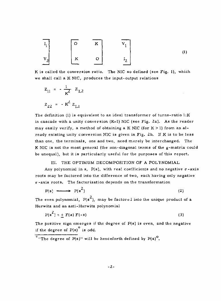
0 K V1
2K 0 12(
K is called the conversion ratio. The NIC so defined (see Fig. 1), which
we shall call a K NIC, produces the input-output relations
Z ~1I= - K_ ZL2
K
= - K ZLl
The definition (1) is equivalent to an ideal transformer of turns-ratio 1:K
in cascade with a unity conversion (K=l) NIC (see Fig. 2a). As the reader
may easily verify, a method of obtaining a K NIC (for K > 1) from an al-
ready existing unity conversion NIC is given in Fig. 2b. If K is to be less
than one, the terminals, one and two, need merely be interchanged. The
K NIC is not the most general (the non-diagonal terms of the g-matrix could
be unequal), but it is particularly useful for the purposes of this report.
III. THE OPTIMUM DECOMPOSITION OF A POLYNOMIAL
Any polynomial in s, P(s), with real coefficients and no negative o-axis
roots may be factored into the difference of two, each having only negative
a -axis roots. The factorization depends on the transformation
P(s) - F(s ) (2)
The even polynomial, P(s2 ), may be factorel into the unique product of a
Hurwitz and an anti-Hurwitz polynomial
P(s 2 ) - + F(s) F(-s) (3)
The positive sign emerges if the degree of P(s) is even, and the negative
if the degree of P(s) * is odd.
0*I"The degree of P(s)" will be henceforth defined by P(s)
-2-

V 1 I ZNCz
I-KI1
1 2 1 1 1K Z
1 K
a) NIC Defintd b) NIC FntosKzLi - 22FIG. 1- -THE IDEAL NIC AND ITS FUNCTIONS
1: K
NIC
IDEAL I_ _ __ _ __ _ _
a) K NIC Equivalent Circuit
K NIC
(K -K) K= 1K1
MHOS
bl, Obtaining K NIC From Unity NIC
FIG. 2 -- THE K NIC

This factoring process may be represented pictorially, as in Fig. 3,which shows the identification of LHP roots of P(s 2 ) with F(s) and RHP
jW~
oO
0 0
F(s) F(-s)
FIG. 3--s PLANE FACTORING OF P(s ) = F(s). F(-s).
roots with F(-s). The s-plane representation of the factorization givesan intuitive explanation for why we cannot have negative or-axis roots.P(s 2), being an even polynomial, exhibits quadrantal symmetry in thes-plane. Negative a-axis roots of P(s) are of the form (s + a- 0), hichupon transformation (2) becomes (s2 + a- 0). It is clear from its s-planerepresentation that this term cannot be the product of LHP and RHP factors
(see Fig. 4). jA
_ _ _ 0
t ° I
FIG. 4--s-PLANE ROOTS OF (s + a-0).
The reader might conjecture that a double-order negative a--axisroot could be thus factored. However, just as there are residue condi-tions on the jw-axis poles of positive real [p. r. ] functions, negativea--axis roots have similar restrictions in RC active synthesis.
Methods to handle negative
a-axis roots will be discussed in a later section.
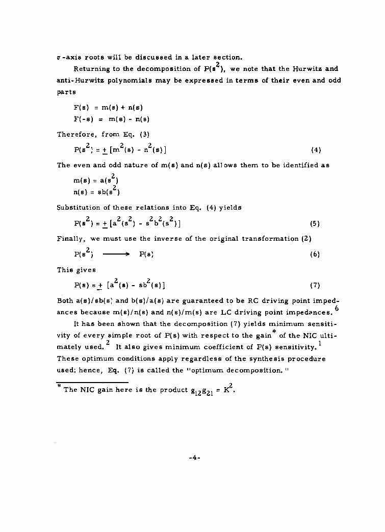
Returning to the decomposition of P(s 2), we note that the Hurwitz and
anti-Hurwitz polynomials may be expressed in terms of their even and odd
parts
F(s) = m(s) + n(s)
F(-s) = r(s) - n(s)
Therefore, from Eq. (3)PsZ = + [m 2 s) - n ]2 (4)P i - s (s)]
The even and odd nature of m(s) and n(s) allows them to be identified as
m(s) = a(s2 )
n(s) = sb(s )
Substitution of these relations into Eq. (4) yields
P(s ) = + [a2(s ) - s2b2(s2)] (5)
Finally, we must use the inverse of the original transformation (2)
P(s ) - P(s) (6)
This gives
P(s) = + [a (s) - sb2 ()] (7)
Both a(s)/sb(s and b(s)/a(s) are guaranteed to be RC driving point imped-
ances because m(s)/n(s) and n(s)/m(s) are LC driving point impedances. 6
It has been shown that the decomposition (7) yields minimum sensiti-
vity of every simple root of P(s) with respect to the gain of the NIC ulti-21
mately used. It also gives minimum coefficient of P(s) sensitivity. 1
These optimum conditions apply regardless of the synthesis procedure
used; hence, Eq. (7) is called the "optimum decomposition.
The NIC gain here is the product glg 2 1 = K2
-4-

IV. RC-LC TRANSFORMATION AND ODD PART IMMITTANCESYNTHESIS
The synthesis problem is related to the successful decomposition of
a ratio of two polynomials (a rational immittance function); hence, we
must relate the optimum decomposition of the preceding section to the
decomposition of a polynomial ratio. This can be best done by applying
a transformation similar to (2) to an immittance function and investigating
the resulting function.
A transformation similar to (2), which furthermore embodies a physi-
cal significance, can be found from the RC-LC network equivalence:
Z I P(s) z P(s (8a)
RC S- Q LC Q(s)
Y = s P(s) Y = P(s) (8b)RC LC Q(S
These relationships are those which emerge when each of the R's of an
RC network is replaced by L's of equal value to form an analogous LC7network. The RC-LC transformations is the mathematical expression
of the equivalence (8) and is given byZ (s) -- -- sZ(B 2) (9a)Y (s) -- -- _I Y(s2) (9b)
Is
Consider an admittance function
m +nY(s) = m1 + 1n (10)
The odd part of this admittance is given bymn -imn
m2 n1 -M1 n2OD Y(s) = Z (11)m2 - n2
We may note the similarity of the denominator in Eq. (11) to the decom-
position, Eq. (4). The identification which facilitates the RC active
-5-
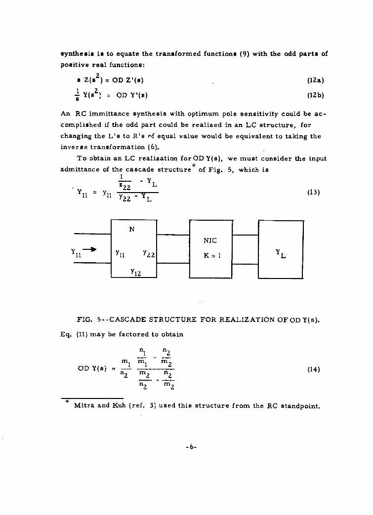
synthesis is to equate the transformed functions (9) with the odd parts of
positive real functions:
s Z(s) OD Z'(s) (12a)
-1 Y(s = OD Y'(s) (12b)
An RC immittance synthesis with optimum pole sensitivity could be ac-
complished if the odd part could be realized in an LC structure, forchanging the L's to R's nf equal value would be equivalent to taking the
inverse transformation (6).
To obtain an LC realization for OD Y(s), we must consider the input*
admittance of the cascade structure of Fig. 5, which is1z2 2 L
N
NIC
YI 11Yll Y ?. K = 1i
YI?
FIG. 5--CASCADE STRUCTURE FOR REALIZATION OF OD Y(s).
Eq. (11) may be factored to obtain
n 1 n2m1 m 1 m2
OD Y(s) = 1 (14)
Mitra and Kuh (ref. 3) used this structure from the RC standpoint.
-6-

which suggests the identifications
m m I n1 n2l-' Y = , ' ' Y m ; Case A (15)
Or, Eq. (11) may be factored in a different manner to obtain
n I n I n
OD Y(s) = - n (16)m 2 n2 m 2
m 2 n 2
which suggests the identifications
nl_ n2 1ml"m1 Y Y 2 ; Case B (17)Yl m 2nZ M 2 31 L nL 2
The network, N, is in both cases recognized to be the lossless network
realized in the Darlington method of synthesizing a driving-point admittance
in terms of a lossless network terminated in a one mho conductance. 8
Furthermore, the load admittance is an LC driving-point function. It
follows that in Case A
YlZ n(18)
In Case B
nl 1- - m 2 (19)
As in the Darlington synthesis, Case A and Case B are mutually
exclusive. Moreover, the usual difficulty of making y12 a perfect square
applies. However, we are awarded an additional degree of freedom be-
cause in starting from the odd part, the even part is not uniquely deter-
mined. Hence, any positive constant may be added to the even part,2which will quite often allow us to make Yl2 a perfect square without re-
sorting to augmentatioli.
-7-

The Darlington realization is always possible, therefore, this reali-
zation of OD Y(s) is always possible. To obtain the RC admittance function
which precipitated the problem, one needs merely to change all of the L's
to R's of the same value.
These remarks apply equally well on the dual basis as the following
example will illustrate.
Example: Let
Z(S) = 36s 2 + 26s + (
z-s)7= ( ?_ )36s + 8s + 1
This, upon transformation (IZa), yields
ODZI(s, =36s 5 + 26s 3 + 2s
36 s 4 + 8s 2 + 1
The impedance, constructed from its odd part, is
6s 3 + 2s2 + 4s+ 1
6sZ + 2s + I
As in the Darlington synthesis, the next step is to construct the even part
IEV Z'(s) =34+1 Z+36s 4 + 8s 2 + 1
Hence, we must use Case A and make the dual identifications of those
in Eqs. (14) and (17)
2s2+ 1 1Zl1 Zs =s+
6s 2 +1 1
=
Z ZsZL 2
'6s Z + 1
-8-

These may be used to obtain the LC realization of Fig. 6. Changing
the L's to R's of Equal value yields the RC realization in Fig. 7 of
the original function, Eq. (20).
Not all problems can be worked out as easily as this one. The Dar-
lington synthesis can and frequently does depend on ideal transformers in
the lossless network. Mitra and Kuh have suggested an excellent method
1 3 NIC
Z(s) - - K =LD 2
HENRYS & FARADS
FIG. 6--LC REALIZATION OF Z(s) =36s5 + 26s + 2s
36s 4 + 8s 2 + 1
NIC
Zls) T 2- K=1 l 2
OHMS & FARADS
36s2 + 26s+ 2FIG. 7--RC REALIZATION OF Z(s) 3
36s + 8s + 1
-9-

3
for eliminating ideal transformers from the cascade structure. Once
one has obtained the network parameters, Eq. (15) or (17) and (18) or (25),
he may realize y 1 satisfying the zeros of yl 2 ( by the zero-shifting and re-
moving technique or, at worst, as a balanced lattice). This procedure
will actually realize a network with parameters
Yll H yl 2, and, y , (21)
Examination of Eq. (13) reveals that it may also be written as
2
Y- 1 (22)¥11 11 Yll Y -" Y L _(Z
Furthermore, this is entirely equivalent to
y - 1H~'2) (23)
H y2 2 -
Hence, the admittance Eq. (13) may also be obtained from the network
Eq. (21) with its output load given by
Y' = H 2 ,z - y 2 YL (24)
2Fig. 8 shows the implementation of this. Aside from H 2 which mustbe entirely negative, the remaining portion of Y' H2 yZ2 -y' 2 , may be
a sum of positive and negative admittances
H -Y?-2 - - Y+ - Y (25)
These admittances may be placed on appropriate sides of the NIC for
the final realization of Fig. 9.
We now have at our disposal fairly general methods for minimum
pole sensitivity synthesis. However, these are limited by some minor
practical drawbacks. The most serious of these is that one may not
always obtain a common-ground structure. A structure which solves
-10-
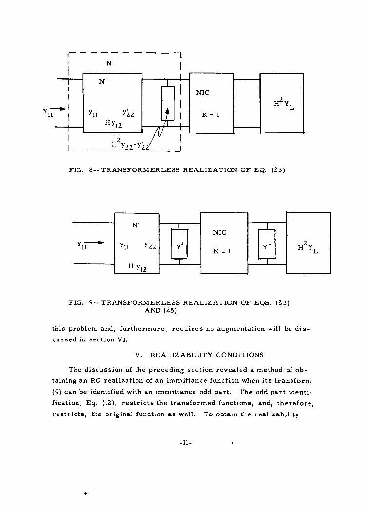
N iN'
I NIC
Yll - - - "Y 2K 1HZ YL11 Yll =
1 H y -z
FIG. 8--TRANSFORMERLESS REALIZATION OF EQ. (23)
N' NC H L
y 1 1 " Y l l Y ? Y K I 'YH 2 '
H y12
FIG. 9--TRANSFORMERLESS REALIZATION OF EQS. (23)AND (25)
this problem and, furthermore, requires no augmentation will be dis-
cussed in section VI.
V. REALIZABILITY CONDITIONS
The discussion of the preceding section revealed a method of ob-
taining an RC realization of an immittance function when its transform
(9) can be identified with an immittance odd part. The odd part identi-
fication, Eq. (12), restricts the transformed functions, and, therefore,
restricts, the original function as well. To obtain the realizability
-11-

conditions which limit this technique, we must study the properties of the
odd parts of positive real immittances.
The degree of the numerator of a p. r. immittance can at most be one
greater than that of the denominator. 9 Consider the immittance
G(s) =m +nm 2 + n 2
Its odd part is given as
m2n 1 - mI nOD G(s) = m2 n2
Since, at most,
o 0nl = m 2 + 1
or
o 0m I n2 +1,
the degree of the numerator of OD G(s) can be no more than one greater
than that of the denominator. In other words, if
ODG(s) N(s) (Z6a)
then
N(s)° < D(s) ° + 1 (26b)
Consider
Z(s) = P(s)
Eq. (12a, gives
P(s)2OD Z(s) = s )
Q(8)
Hence, Eq. (26b) yields
(s P(s ))0 < Q(s )0+ 1
-12 -
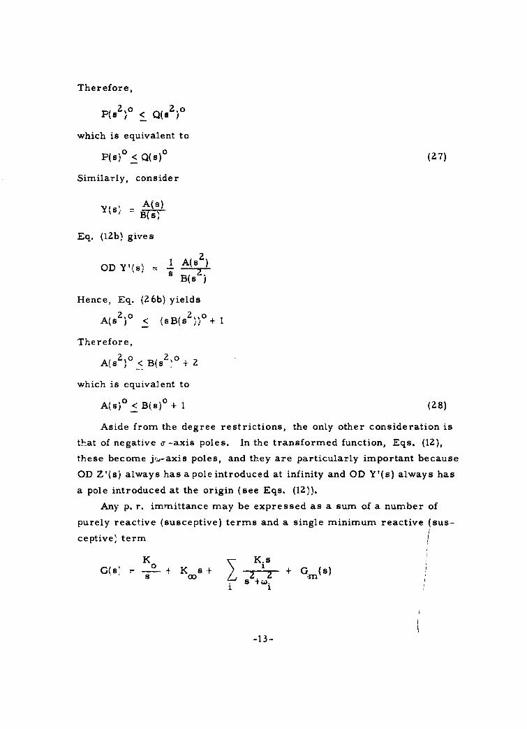
Therefore,
P(s ) < Q(s 2)
which is equivalent to
P(s) ° < Q(s)° (27)
Similarly, consider
V(s, =A(s)
Eq. (12b) gives
OD Y'(s) 1 A(s)
SB(s L)
Hence, Eq. (26b) yields
A(s ) < (sB(s i) + 1
Therefore,
A(s ) < B(s I + 2
which is equivalent to
A(s) ° < B(s)° + 1 (28)
Aside from the degree restrictions, the only other consideration is
th.at of negative a -axis poles. In the transformed function, Eqs. (12),
these become jf-axis poles, and they are particularly important because
OD Z'(s) always has a pole introduced at infinity and OD Y'(s) always has
a pole introduced at the origin (see Eqs. (12)).
Any p. r. immittance may be expressed as a sum of a number of
purely reactive (susceptive) terms and a single minimum reactive (sus-
ceptive term
K - K.i s
G(s - i K s + + Gm(s)
-13-

GM denotes a minimum reactive (susceptive) immittance. The residue
condition for p. r. functions requires that
K. real and Ki> 0, Vi
The odd part of the immittance is given by
K K.sODG(s)= + K s+ I + OD Gm(S)
1
This follows from the linearity of the operation of taking the odd part. From
the foregoing discussion it is clear that OD Gi (s) will have no jw-axis poles.
Hence, all jw-axis poles in OD G(s) must have real and positive residues.
Therefore, negative o- -axis poles of a given impedance must have positive
residues, and negative a--axis poles of a given admittance divided by s
must have positive residues.
The residue condition is more succinctly stated in terms of the trans-
forms (9), as all jw-axis poles of the transformed function must have real
and positive residues. The residue condition in the pole at infinity of
OD Z'(s) and that at the origin of OD Y'(s) implies that
Z(c0) > 0 (29a)
Y(O) > 0 (29b)
These restrictions completely define the functions which we may realize
by the methods of this paper. The realizability conditions are repeated
here for completeness-
The restrictions on Z(s) = N(s)/D(s) are
i) N(s) ° < D(s) ° , (30a)
ii) Negative or-axis poles have real and positive residues, (30b)
iii) Z(co. > 0. (30c:
The restrictions on Y(s) = A(s)/B(s) are,
i) N(s) ° < D(s) ° + 1, (31a)
ii) Negative o-axis poles of 'Y(s)/s have real and positive (31b)residues,
iii) Y O) > 0. (31cl
-14-

0
The most effective method of dealing with the negative a--axis
poles is to remove them after the transformation(9), as jw-axis poles,
in a manner analogous to the Brune preamble. 10 Realizable functions
which have no negative a- -axis poles shall be called "minimum active.
It must be emphasized that the restrictions, (30 and 31), apply
only for the synthesis discussed. Sipress has shown that any rational
function can be realized with R's, C's and one NIC. 11
VI. THE CASCADE-FEEDBACK STRUCTURE
The most general one NIC structure, which may be used for the re-
alization of a driving point immittance, consists of a passive, reciprocal,
3-port with an NIC imbedded (see Fig. 10).
0+1+ NC
Yll 0- N I
01 -~ .l N
FIG. 10--MOST GENERAL SINGLE NIC DRIVING POINTIMMITTANCE REALIZATION
Consider the parameters of the passive network, N, to be specified
on the admittance basis
I? Y12 Y 2 Y2 E] (32)
13 Y13 Y23 Y31 E3

The NIC constraints, Eq. (1), when applied to Eq. (32) yield
2 2 2S - 1 2 y 1 3 (33)
11= ll - ZY2 2 -K y 3 3
From this we may see that the value of YZ3 is immaterial, and may, for
convenience, be set equal to zero. A simplification results from making
the identifications
yll = Ylla + Y llb
Y12 Yl2aY13 Y12b(34)
Y22= Y22a
Y33= Y22b
The relations (34), when inserted into Eq. (33) give
SK 2 2Yl2 a K__________Y 111- Ylla K + Yllb- Z (35)
Y2 2 a - K Y22b K Y22bY22a
This is readily seen to be the cascade output, through an NIC, of two
parallel input, two-port structures, as is pictured in Fig. 11.
Duality may be used throughout this development and the dual struc-
ture of Fig. 12 is specified by
E K z2 2
Z = = Il a K- + Zllb 12b Z (36)K Za a'zZ2b Z22b Kz2a
The structures introduced here, although not the most general
because the NIC used is not the most general, will prove quite power-
ful in the solution of minimum sensitivity synthesis problems.
-16-

IN aNCNb
Na
z laz 2
Z lZa
NIC
N 1b
FIG. 12 -CASCADE- FEEDBACK IMPLEMENTATION OF EQ. (36).
-17-

VII. OPTIMUM POLE SENSITIVITY SYNTHESIS TECHNIQUE
A minimum active admittance, which satisfies the realizability
conditions (31), may be related to the odd part of a p. r. admittance
through the transformation (9b). The odd part of the admittance may
be used to compute the even part
N( sEV Y'(s) = Z
m2 - n2
The numerator of the even part exhibits quadrantal symmetry in the
s-plane. Therefore, it may be decomposed in the manner of Eq. (4),
yielding
2 2
EV Y'(s) =m z 2 n 2
The right hand side of this equation can be represented as the sum of
two even part components, i. e. ,
2 2mI -nEVY '(s) - +m 2 - n2 m 2 - n 2
Each of the terms on the right hand side of this equation may be iden-
tified as the even part of a p. r. admittance
2
EV Ya(s) = z zm 2 - n2
2
EV Yb(s) = Z Zm 2 - n2
These even parts may each be used to generate a minimum susceptive
admittance
-18-

m + nYa(s) = 2
a m I+n'
m2 + 2
l+n
Yb(s) = m2 + n2
The parameters which realize the pertinent odd parts (see Eqs. (15),
(17), (18), and (19)) may be found by inspection to be
m m
a =l a n' l2a n
(37a)m n2
Y2a n ' La = m 222fl
n1 nYb: Yllb= m ' lZb m
n m (3 7b)Y zb m ? L Yb --n
n2
These networks are, as expected, loaded by each other, i. e.
Y22a = YLb' Y22b = YLa
Hence, the cascade-feedback configuration of Fig. 11 is possible.
This procedure has allowed us always to obtain y 2 's which are
perfect squares, thus ending any argument as to the necessity of
augmentation. Moreover, since m and n are even and odd parts re-
spectively oi a Hurwitz polynomial, their zeros are all on the jW-axis,
and the networks are always amenable to a ladder (common-ground)
realization.
Example: Let
30s 2 + 282sY(s) = Z (38)
s -5s+4
(Note: Y(O) = 0, satisfying condition (31c).
-19-
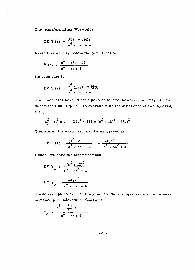
The transformation (9b) yields
DY(s) 30s 3 + 282s
s4 5s z + 4
From this we may obtain the p. r. function
22 + 33s + 72Y'(s) = + s
s + 3s+ 2
Its even part is
EV Y(s) = s4 25s 2 + 144
s 4 5s z + 4
The numerator here is not a perfect square; however, we may use the
decomposition, Eq. (4), to express it as the difference of two squares,
i. e.,
2 2 42 2 2m i -n 1 = s 4 252 + 144 = (s + 12) - (7s)
Therefore, the even part may be expressed as
EVYI(s, (s +12) 2 + 49s24 4s -5s + 4 s " 5s + 4
Hence, we have the identifications
EV Y = 2s+ 12)2
a s 4 5s +4
_49s2
EV Yb 4 2b 4 5se + 4
These even parts are used to generate their respective minimum sus-
pectance p. r. admittance functions
2 50s + - s+72
Y a= z
s +3s+ 2
-20-

Y =49/3 sb s +3s+2
At this point a convenient check is to see that the sum of Y a and Yb is
equal to Y'. The network parameters may now be identified, according
to Eqs. (37), as
2s + 72 s 24
Ylla 3s
(Bs2 + 12) s 4
Yl2a - ( s -+2 "S"5
Y s 2+ 2 + 2Y22a = Lb = Ts + 2
49/3 sYllb = +s +2
-7sYl2b 2s +2
3s
Y22b = La 3s
s +2
Fig. 13 gives the LC realization indicated here, with the negative ele-
ments through the NIC, we obtain the final realization (Fig. 14) for Eq.
(38).
In general the negative elements do not appear adjacent to the NIC
in the ladder realization of the separate networks. However, the method
of transformerless synthesis discussed in section IV, coupled with the
use of the NIC conversion ratio, K, can always surmount these diffi-
cultie s.
Suppose that in attempting to eliminate transformers from the
networks of Fig. 11, the two associated constants, Ha and Hb, are un-
equal. The NIC turns-ratio may then be adjusted such that
-21-

1/3
1/7
1/ NIC
-1/4 3/28
Y(s) 1/20 -3/10 T 4 3
HENRYS & FARADS
FIG. l-i--LC REALIZATION OF Y(s) = 30s 3 + 282s
s - 5s +4
1/7 7/2
1/4 1 /4 NIC 3/2
Yl(s)--, 1/20 K I
___FT_ 14/3
OHMS & FARADS
30s2 + 282sFIG. 14--REALIZATION OF Y(s) 4s
-22-5 4

2H a
K = a (39)Nb
It is easily seen that for this value of K both networks satisfy Eq. (29).
For an example, let us reconsider the same problem, Eq. (38),which we have just solved for a unity conversion NIC. The zero shifting
12and removing technique will realize Ylla satisfying the zeros of Yl2a'such that
2s + 72
Y11a -= 3s
2s + 12
Y12a - 3s
22 s + 12Y2a 3s
Comparing these to the previous set, we see that
H =1a
Furthermore,
H2 10a Y22a Y22a 73s
Yll - - ' " li 1/20 1/4 4 "-z J 3/10" -Y22
HENRYS & FARADS
FIG. 15--TRANSFORMERLESS REALIZATION OF Na
-Z-3-

These parameters define the network of Fig. 15, which is seen to be the
same as Na of Fig. 13. The same technique applied to the parameters of
Vb yields
49/3 sYllb = +-s +2
49/3 s12b = 2s +2
49/3 s!YZ2b=
s +2
This realization, shown in Fig. 16, gives
7Hb =
Furthermore,
2Hb Y22b - Yb = 0
The LC realization of Fig. 17 is made by combining the two networks
with an NIC of conversion ratio given by Eq. (39) as
K 949
The final realization obtained by changing all of the L's to R's of the
same value is given in Fig. 18.
-24-

3/49 49/6
49y l l - --. Y ? - Y ?
0
HENRYS & FARADS
FIG. 16--TRANSFORMERLESS REALIZATION OF Nb
49/6
3/49
Y l(s )- -- 1 12 0 -1 1
K= 9
HENRYS & FARADS30s3+ZgZs
FIG. 17-- ALTERNATE LC REALIZATION OF Y(s) = 4
s -5s +4
-25-

3149 49/6
1/3
•A1/4
NIC
Y (s) 1/20 K 9/49
OHMS & FARADS
30s z + 282s
FIG. 18--ALTERNATE REALIZATION OF Y(s) =
s -5s+4
VIII. MINIMUM SENSITIVITY IMMITTANCE SYNTHESIS
TECHNIQUE
The root and coefficient sensitivities of a polynomial are dependent
only upon the decomposition used, and not upon the subsequent method
of synthesis. Hence, if both the numerator and the denominator can
be decomposed in the manner of Eq. (7), an optimum sensitivity
synthesis may result. In the previous sections methods dealt only with
minimum sensitivity denominator decomposition; in this section we shall
attempt to extend those techniques to the numerator decomposition as
well.
Since the decomposition, Eq. (4) is to be applied to the numerator,
a further restriction must be added to (30) and (31). When the minimum
active function has been obtained, its reciprocal must also be minimum
active (with odd part transformed functions, we must, of course, over-
look the zero at the origin, which always appears in the odd part). In
other words, we may only handle functions with no poles or zeros on
the negative a-axis.
-26-

Tle procedure for minimum sensitivity immittance synthesis isquite s imilar to that of section VII. The difference here is that bothnumerator and denominator are immediately decomposed, whereas
in the former case the denominator decomposition was not undertakenuntil tlxe corresponding even part was obtained. On the impedance basis,after the transformation (9a), we have from Eq. (12a)
2 2
ODZ'(s) = s Z(s) = m (40)m 2 - n 2
That thLis decomposition can always be effected follows from the dis-cussion above, disallowing negative a- -axis poles or zeros of Z(s). Theright h.and side of Eq. (40) can be factored into the sum of two odd parts
2 2s m 1 -s n101D ZI(s) = -4 Z + 2 Z (41)
m 2 - n2 m 2 - n 2
Each oif these terms can be identified separately as the odd part of a p. r.
functioxi
2
OD Z Sm1 (4Za)a m2 -n
2-s nI2
OD Zb -- Sn (42b)m 2 - n2
The even parts corresponding to these may be generated such that theirnumeraLtors are perfect squares. This follows because there is an arbit-
rary constant which may be added to the even part when it is determinedfrom t1ae odd part; or, the odd parts of the given of a given function mayalways be augmented. The constant guarantees the existence of one more
unknow m than the number of equations. Therefore, the final equation may
be that which constrains the numerator to be a perfect square.
-27-

The even parts, then, areI I
mlm2 - nln2 ,
EVZ = -1 M 2 4 _.(m~m. - n{n2 (43a)
S 2 Rational
m{'m 2 -r j'n z
__________-___r___ 43b
EV Zb = (43b)m 2 2 Rational
The reader may note that a further restriction is that the two even partsmust be chosen such that the functions Z a and Zb are of opposite case,
Eqs. (15) and (17). Once we have attained this point, the synthesis is
straight-forward and follows the development of section VII from Eq. (37).
An example will amplify the above presentation of the synthesis procedure.
Example: Let
1 - sZ(s) = 4- (45)
Upon applying the transformation (9a), we obtain from Eq. (IZa)
OD Z'(S) = s-
4- s
This may be factored in the manner of Eq. (41) as
3OD Z'(s) s + -S
4- s 4-s
The identifications (42) give
OD Z =a4- s
3OD Zb = -
4- s
-28-

The p.r. impedance Za must be of the form
S2s+a0=a 2 s2+a1 saZ =
a s+.
Furthermore, it must obey
Za1s - s(a 2 s +a 0)= s: 14+[ 2a2s4+a0)-a1s
Rational
The method for obtaining a rational z12 is essentially that of Kinariwala,1 3
which is to solve the quadratic equation for the coefficients which will
yield a perfect square, i. e.
c 2 s 4+ c s 2+ cO: c =+ 2N/c4c_ (46)-1 0~ 1- 2 0
For higher order functions, this problem is more readily solved by
augmentation of the odd part. The solution of the present problem is1
a = a = 0, a 1
Thus, the impedance Z a is given by
Z 1/2 s
a s+T
Zb must then be of the form
b 2s2 + b s + b0
b = s
It is restricted by
2b1 s - s(b 2 s 2 + b0 ) = 's3 2(b 2 s 2 + b0 ) - b1sZ
Rational
The solution of these relations is given by
b2 = 1, b1 = 2, b0 = 4
-29-
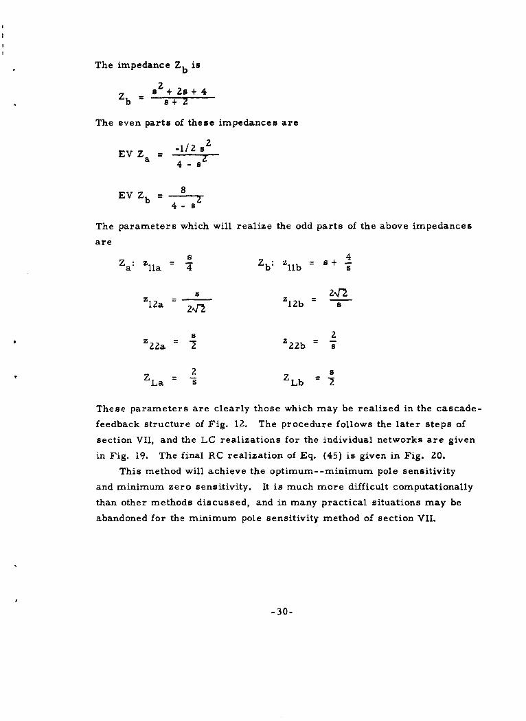
The impedance Zb is
z
b s +2s+4
The even parts of these impedances are
EVZ = -1/2 S
EV Zb = 8
a 4 - s Z
4- s
The parameters which will realize the odd parts of the above impedances
areZa: z - Z: bz s +
a~ ila b lb
z2%r
s 2Z 22a 72 Z22b -
S2ZLa - ZLb=
These parameters are clearly those which may be realized in the cascade-
feedback structure of Fig. 12. The procedure follows the later steps of
section VII, and the LC realizations for the individual networks are given
in Fig. 19. The final RC realization of Eq. (45) is given in Fig. 20.
This method will achieve the optimum- -minimum pole sensitivity
and minimum zero sensitivity. It is much more difficult computationally
than other methods discussed, and in many practical situations may be
abandoned for the minimum pole sensitivity method of section VII.
-30-

1 1/2 -1
z, 1- .-_-- z- b--1/4 z' _ 1/2 Z'
HENRYS & FARADS
a) LC Realization of b) LC Realization of
3
ODZ = OD Zb -SOZa 7---7'- b4-s 4-s
FIG. 19--THE COMPONENT NETWORKS FOR THE LC REALIZATION
OF OD Z = - ' -
4-s
1/4
0~NIC
Z(s) 1/l K = I
OHMS & FARADS
FIG. 20--OPTIMALLY SENSITIVE REALIZATION OF Z(s) =-s
o31-
IX. CONCLUSIONS
Methods have been presented for RC active driving-point synthesis
which yield semi-unique structures from a straight-forward realization
procedure. The networks obtained are usually practical (e. g. , common-
ground) and not given to an excess of elements. The limitations are few
and usually may be circumvented by augmentation of the given function.
A problem which warrants further consideration is, "Can any function,
by suitable subtraction of constants (resistances) from it and its reciprocal,
be made minimum active or minimum sensitivity (section VIII. ) realizable?"
REFERENC ES
1. Horowitz, I. M., "Optimization of Negative-Impedance ConversionMethods of Active RC Synthesis, " Trans. IRE, Vol. CT-6, No. 3(September 1959), pp. 296-303.
2. Thomas, R. E. , "A Classification of Critical Frequencies ofActive Network Functions, " to be published in IRE Trans. on CircuitTheory.
3. Mitra, S. K. and Kuh, E. S. , "Synthesis of Active Driving-PointImmittance Functions, " University of California, Electronics ResearchLaboratory, Series No. 60, Issue No. 339, December 27, 1960.
4. Kuh, E. S. , and Pederson, D. 0. , Principles of Circuit Synthesis,p. 70, New York: McGraw-Hill Book Co., 1959.
5. Guillemin, E. A. , Synthesis of Passive Networks, pp. 279-290,
New York: JohnWiley and Sons, Inc., 1957.
6. Kuh and Pederson, op. cit. , pp. 148-152.
7. Kuh and Pederson, ibid., pp. 148-152.
8. Guillemin, op. cit., pp. 358-362.
9. Kuh and Pederson, op. cit., p. 83.
10. Guillemin, op. cit., pp. 343'-346.
-32-

11. Sipres, j. M., 'New Results in the Synthesis of Active RC Networks,Bell elephone Labs., Murray Hill, N. J., Technical Memorandom,MM-60-2173-3.
12. Kuh 4rid Pederson, op. cit., pp. 106-114.
13. Kinarwala, B. K., "Synthesis of Active RC Networks," BSTJ,Vol. 38 (September, 1959), pp. 1269-1316.
-33-

C~iif qLN.VAc Rcsa-,.t, Library Radiation L..buratoryNavy Department Boulder Laboratories John. Hopkins UniversityWashington 25, D. C. National Bureau of Standards 1315 St. Paul Street
- Attn: Cod, 427 Boulder. Colorado Baltimore Z, Maryland460 Z Atto: Mrs. Victoria S. Barker I Atto: Librarian
Director, Naval Rese'arch Laboratory Assistant Secretary of Defense. Department of Elect rical EngineeringWashington Zlo, 1). C. Rteseacrch and Development Board Yalu, UniversityAttn! Code 2000 -De*partment of Defenaro I New Haven, Connecticut
5250 - I W.islingtont Z5. D. C.Willow Run Research Center
Commanding Officer Watson Laboratories Library University of MichiganO)ffice of Naval Rese~arc, Br. Office. AMC. Red Bank, Ne. JerseyYplntMhia1000 Geary Street I Attn; ENA.ZSI I Attn: Dr. K. Siegel
* Sun Francisco 7, California -Armed Services Technical Information Agency Georgia Institute of Technology
Chief, Bureau of Ships Attention: TIPDK Atlanta, GeorgiaNavy Department Arlington )fall Station I Attn: Mrs. j. renley Crosland,Washington Z5, D. C. 10 Arlington 12, Virginia LibrarianAton: Code 838
Technical Reports Collection Prof. Vincent C. RideoutChief, Bureau of Ordnance 303A Pixrce Hall Dept. Electrical Enginee ringNavy Department Harvard Univvrsity University of WisconsinWoshingtont Z5, D. C. I Cambridge 35, 1ascaet Madison 6, WisconsinAttn: Kati -
Antenna Laboratory Hughes Aircraft CompanyDirector, Naval Ordnance Laboratory Ohio State University Rlesearch and Development LibraryWhite Oak, Maryland Resoearch Fouindation Culver City, California
Columbus. Ohio I Attn: John T. MilchCommander I Attn: Dr. C. T. TaiU. S. Naval Electronics Laboratory Douglas Aircraft Co., Inc.San Diego, California - Brooklyn Polytechnic Institute El Segundo Division
Microwave Research Institute I El Segundo, CliforniaCommander 155 Johnson StreetNaval Air Development Center Brooklyn I, New York Hughes Aircraft Co.Johnsvilie, Pennsylvania I Attn: Dr. A. Oliner Antenna Item. Dept.Attn: AEEL - Bldg. 12, Rm. 1617
Mathematics Research Group I Culver City, Caltf.U. S. Naval Pamst G raduate School Now York UniversityMonterey, California 25 Waverly P, ccAitn: Librarian New York, New York Radio Corporation of America
I Attn: Dr. M. Kline Laboratories, Elect, Rlev.Naval Air Missile Test Center Princeton, New JerseyPoint Mugu, California Department of Electrical Engineering I Attn: Dr. W. M. Webster, Dir.
Cornell UniversityChief, Bureau of Aeronautics Ithaca, New YorkNavy Department I Attn: Dr. If. G. Booker Varian AssociatesWashington Z5, D. C. 611 Hansen WayAttn: EL- 5I Antenna Laboratory Palo Alto. California
Electrical Engineering Research Lab I Attn: Technical LibraryCtininnanding Gene ral University of IllinoisSignal Corps Engineering Laboratories Urbana, Illinois Bell Telephone Laboratories, Inc.Evans Signal Laboratory Area I Aton: Dr. P. E. Moyaa Central Serial RecordsBuilding 27 Technical Information LibraryBelmar, New Jersey PRssearch Laboratory of Electronics 463 West St.Aton: Technical Documents Center Document Rtoom I New Yorkt 14, New York
Massachusetts Institute of TechnologyMr FrAnk J. Muttlin Cambridge 39, Massachuasetts Boeing Aircraft CompanyDepartment of lectrial Engineerinig I Aitn: Mr. .1, Hewitt Physical Research UnitCalifoarnia Institutt- of Tuchuogy Seattle 14, WashingtonP'asadena, Stanford Research Institute I Attn: Mr. R.. W. IllmanC.,itifnrr.ia Y74 Commiercial
I ilintcird, California The Rand CorporationCommanc~ing (-,.-ral Alltn. Dr. John , Btolijohn, Div. of Ele*ct. Eng. 1700 Main StreetWright Air Development Center Santa Monica, CaliforniaWright Patterson Air Force Base, Electrical Engineering Department I Aton: Margaret Anderson, LibrarianOhio , University of TexaAton: WCRtEO-Z Boa F, U~niversity Stationi Federal Telecommunications
I Austin, Texcas Laboratories, Inc.Commanding General 500 Washingirn AvenueRome Air Development tnoler Electronics Reserarch Laboratory Nutley, New JerseyGriffis@ Air Force Basn Stanford University I Aton: A. K. WingRome, New York Stanford. CaliforniaAton: ItCRW . I Attn, Applied Electronics Laboratory rlectronics Laboratory
Document Library General Electric, Electronics ParkCommanding General Syracuse, New YorkSignal Corps Engineering L.aboraloriea Rlanidall tItorgin Laboratory of P'hysics I Aton: Lloyd DeVoreFort Monmouth, New Jr rsey University of PennsylvaniaAttn, SIGEL-SMU-riif, I Philadtelphia 4, Pennsylvania Technical University
MOII-Magnilic Matei atls Depa rtment of Electrical Enginee ringColumbia Radilation LaborAtoritis Dr~ll, Holland, VIA ONR London
Commeander Ccuiumbia University I Aton: Prof. j. P. SchoutenAir Force Ctfici, of Scientific Resi:. rch S38 W. IZ(th St.Air Research ani rlelo 1,ment Command New York 47, New York CAmbridge UniversityWseiiilon 2i,. DC. I Atto; Librmtrian Nadiophysicso Division
Cavendish LaboratoryGoinonitfing Olficr Carl A. tdebrg. Hiead Cambridge. England. VIA ONK LondonSquier SIna Laborainiy Electronics Division I Ato: Mr. J. A. RatcliffeYort Moninou!h. New J, roy Denver Mecca ech Institute'Attn. V J1. Kohli- University of lhiovr koyal Technical University
I tDenuior 10. Ciiliir~do i.L~boralory for I elephony and
tienlagon, Wtashington 45., 1). C. Electrical Kniiint-.ring Dep1 artment COPerihAW-n. DenmarkAttn.;I(L lll.nois Plnstfitil, of 're, hmology VIA ONK I,.n'on
Technology (*eniie, I Aton: P'rof. it. L. KnudsenSignhl Gorpm niinie ring I.Abo-friliis Chn ago 16, Ilni
4i rI Mo-nritqh, N-. a Sirs.'y Chaheicrs Insttiue of TechnologyAitn Mr. 0. (.'. W,,.oIlyant Unive~rnity of llori Olboi g, Sweden
L.,lnnsvill., tlcir~. VIA iJNi London011li.o~ hca Sr,,. . I Aton: Appli-I~ leS,(l., tb Attn Peol. 5. iKkiof and Prof. If, Wall,...
Wailicnglon / i I). C. lOe C. J. Iliowkampittent. of in, Umuir.ily of Mi, lilg.in Philipis Research Laboratories
l'rvf-itor '.ohtrib Re r- ian I Ann Arbor, Miihican N. V. Phillip'slieiA rtitiint ot It.tri cal K'nitini,.ring G Iowilampenfab riekienUniviy of Southern Califo~rnia Cihforni,, tositici, ofI t olnotogy Eindhoven. NetherlandsLos Anile.. California la.-cden. Gelmforni I VIA ONR London
I Attn. C. It. tip..Professor N DeClaris Professor Samuel Scoly, HeadCornell University Department of Electrical Enginei-ringIthaca. N-w York CAse Institute a(f Technology
Unive.rsity CircleI Cliviland 6, Ohio