actuator project report - master
TRANSCRIPT

ACTUATOR DESIGN REPORT
DESIGN AND MECHATRONICAL SYSTEMS
Ian Duggan, Bruce Locke, Phil Marlow, Tom Leggett and Jack Hopper

2 | P a g e Cogs ‘O’ War
Contents
1 Table of Contents Figure List ......................................................................................................................................... 5
Table List .......................................................................................................................................... 6
Executive Summary .......................................................................................................................... 7
1. Project Overview ...................................................................................................................... 8
1.1 Project Functions ............................................................................................................. 8
1.2 Requirement Specification ............................................................................................... 8
1.2.1 Technical Requirements ........................................................................................... 8
1.2.2 Manufacturing Requirements .................................................................................. 8
1.2.3 Costing Requirements .............................................................................................. 8
2 Design Specification ................................................................................................................. 9
2.1 Performance .................................................................................................................... 9
2.2 Economy ........................................................................................................................... 9
2.3 Manufacturing Facilities ................................................................................................... 9
2.4 Product Life Span ............................................................................................................. 9
2.5 Service Life ....................................................................................................................... 9
2.6 Environment................................................................................................................... 10
2.7 Size ................................................................................................................................. 10
2.8 Weight ............................................................................................................................ 10
2.9 Maintenance .................................................................................................................. 10
2.10 Materials ........................................................................................................................ 11
2.11 Ergonomics ..................................................................................................................... 11
2.12 Finish/Appearance ......................................................................................................... 11
2.13 Quality and Reliability .................................................................................................... 11
2.14 Industry Standards ......................................................................................................... 11
2.15 Testing ............................................................................................................................ 11
2.16 Shelf life/Storage life ...................................................................................................... 11
2.17 Safety ............................................................................................................................. 12
2.18 Customer ........................................................................................................................ 12
3 Initial Concepts....................................................................................................................... 13
3.1 L –Shaped Design ........................................................................................................... 13

3 | P a g e Cogs ‘O’ War
3.2 U –Shaped Design ........................................................................................................... 14
3.3 Z-Shaped Design ............................................................................................................. 15
3.4 Concept Conclusion ........................................................................................................ 15
4 Screw Selection ...................................................................................................................... 16
4.1 Acme Screws ................................................................................................................... 16
4.2 Ball Screws ...................................................................................................................... 17
4.3 Roller/Planetary Screws ................................................................................................. 17
4.4 Conclusion ...................................................................................................................... 18
5 Gear Type Selection ................................................................................................................ 19
5.1 Spur Gears ...................................................................................................................... 19
5.2 Helical Gears ................................................................................................................... 19
5.3 Herringbone Gears ......................................................................................................... 19
5.4 Bevel Gears ..................................................................................................................... 20
5.5 Gear Type Conclusion ..................................................................................................... 20
6 Actuator Position Selection .................................................................................................... 21
6.1 Actuator Positions .......................................................................................................... 21
7 Euler’s Buckling Force Calculations ........................................................................................ 24
7.1 Extension of Powerscrew ............................................................................................... 29
7.2 Force acting upon the actuator ...................................................................................... 29
7.3 Non-Obstructing ............................................................................................................. 29
8 Screw Opening Timing Calculation ......................................................................................... 31
9 Torque Calculations ................................................................................................................ 32
9.1 Driving Torque ................................................................................................................ 32
9.2 Back driving Torque ........................................................................................................ 34
9.3 Drag Torque .................................................................................................................... 35
9.4 Max Torque .................................................................................................................... 35
10 Motor Selection .................................................................................................................. 36
11 Gear Calculations ................................................................................................................ 37
11.1 Gear Size Calculations: ................................................................................................... 37
11.2 Gear Stresses .................................................................................................................. 39
11.2.1 Lewis Bending Stress .............................................................................................. 39
11.2.2 AGMA Stress Equation............................................................................................ 41
11.2.3 Bending Factor of Safety ........................................................................................ 44
11.3 Gear Calculation Conclusion: .......................................................................................... 45

4 | P a g e Cogs ‘O’ War
12 Mounting Calculations ....................................................................................................... 46
13 Bearing Calculations ........................................................................................................... 47
13.1 Thrust Bearings .............................................................................................................. 47
13.2 Ball Bearings ................................................................................................................... 47
14 Actuator Lifespan Calculations........................................................................................... 49
15 Lubrication ......................................................................................................................... 50
15.1 Grease Lubrication – 0 to 6 m/s tangential gear speed ................................................. 50
15.2 Splash Lubrication – 4 to 15 m/s tangential gear speed ................................................ 50
15.3 Spray Lubrication – Above 12 m/s tangential gear speed ............................................. 50
15.4 Lubrication Conclusion ................................................................................................... 50
16 Parts List ............................................................................................................................. 51
17 Design Conclusion .............................................................................................................. 52
17.1 Technical Requirements ................................................................................................. 52
17.2 Manufacturing Requirements ........................................................................................ 52
18 References ......................................................................................................................... 53

5 | P a g e Cogs ‘O’ War
Figures and Tables
Figure List Figure 1 – L-Shaped Concept Drawing ........................................................................................... 13
Figure 2 - U-Shaped Concept Drawing ........................................................................................... 14
Figure 3 - Z-Shaped Concept Drawing ............................................................................................ 15
Figure 4 - Acme Thread on Screw ................................................................................................... 16
Figure 5 - Ball Screws ...................................................................................................................... 17
Figure 6 - Roller/Planetary Screw ................................................................................................... 17
Figure 7 - Spur Gear ........................................................................................................................ 19
Figure 8 - Helical Gear .................................................................................................................... 19
Figure 9 - Herringbone Gear ........................................................................................................... 19
Figure 10 - Bevel Gear .................................................................................................................... 20
Figure 11 - Position 1 Closed .......................................................................................................... 21
Figure 12 – Position 1 Open ........................................................................................................... 21
Figure 13 - Position 2 Closed .......................................................................................................... 22
Figure 14 - Position 2 Open ............................................................................................................ 22
Figure 15 - Position 3 Open ............................................................................................................ 22
Figure 16 - Position 3 Closed .......................................................................................................... 22
Figure 17 - Position 4 Closed .......................................................................................................... 23
Figure 18 - Position 4 Open ............................................................................................................ 23
Figure 19 - Diagram for Initial Input Values for Euler's Buckling Equation .................................... 24
Figure 20 - Vertical component of force diagram .......................................................................... 25
Figure 21 - Cowl moment force diagram ........................................................................................ 25
Figure 22 - Diagram showing positions of D1, D2, A2 , 𝜶 and Ac ..................................................... 26
Figure 23 - Graph showing at point 3, Force Vs Cowl Angle .......................................................... 28
Figure 24 - Graph showing at point 2, Force Vs Cowl Angle .......................................................... 28
Figure 25 - Graph showing at point 1, Force Vs Cowl Angle .......................................................... 28
Figure 26 - Graph showing at point 4, Force Vs Cowl Angle .......................................................... 29
Figure 27 - Graph showing Velocity vs Time .................................................................................. 31
Figure 28 - Electric GP Motor ......................................................................................................... 36
Figure 29 - Diagram showing values on gear tooth ........................................................................ 39
Figure 30 - Data sheet for Lewis Form Factor ................................................................................ 40
Figure 31 - Diagram showing ht and tR .......................................................................................... 43
Figure 32 - Graph showing Geometry Factors YJ for Spur Gears ................................................... 43
Figure 33 - Graph showing Stress Cycle Factor YN ......................................................................... 44
Figure 34 - Gear Position Setups .................................................................................................... 45
Figure 35 - Pin Joint Size Diagram .................................................................................................. 46
Figure 36 - Bearing Layout .............................................................................................................. 47

6 | P a g e Cogs ‘O’ War
Table List Table 1 – Values for Actuator Position 1 and 2 .............................................................................. 21
Table 2 - Values for Actuator Position 3 and 4 .............................................................................. 23
Table 3 – Initial Input Values for Euler’s Buckling Equation .......................................................... 24
Table 4 - Force values at points 1 and 2......................................................................................... 27
Table 5 - Force values at points 3 and 4......................................................................................... 27
Table 6 - Input values for the Diameter of the screw .................................................................... 30
Table 7 - Force acting upon actuator through cowl opening angle ............................................... 32
Table 8 - Values of Lead, to calculate the driving torque .............................................................. 33
Table 9 - Values of torque through opening degree at Lead of 5mm ........................................... 34
Table 10 - Values of Lead, to calculate the back driving torque .................................................... 35
Table 11 - Table showing selected values as highlighted .............................................................. 38
Table 12 - Showing selected Gear Values ...................................................................................... 38
Table 13 - Values for Tangential transmitted load for each gear .................................................. 39
Table 14 - Showing values for V and Kv ......................................................................................... 40
Table 15 - Showing Lewis Form Factor for each Gear Teeth No. ................................................... 40
Table 16 - Value of Bending Stresses and Factors of Safety for each Gear ................................... 40
Table 17 - Grid for displaying Ko Values ........................................................................................ 41
Table 18 - Summary table of values for Gear Stress Equation ...................................................... 42
Table 19 - Graph showing the Load Distribution Factor ................................................................ 42
Table 20 - Values of tR, ht, mB and KB for AGMA Stress Equation ................................................ 43
Table 21 - AGMA Stress Equations calculated for Gear 1 and 2 .................................................... 43
Table 22 - Reliability values ............................................................................................................ 44
Table 23 - Bending Factor of Safety ............................................................................................... 45
Table 24 - Final Gear Dimensions................................................................................................... 45
Table 25 - Grease and Oil Lubrication comparative matrix ........................................................... 50
Table 26 - Parts Number List for Actuator ..................................................................................... 51
7 | P a g e Cogs ‘O’ War
Executive Summary
Executive Summary We have been tasked to design an actuator for an engineering company that is looking to
manufacture actuators to supply aerospace companies. This report will describe and evaluate
the design process for a new actuator undertaken by a team of 2nd year Mechanical Engineering
students at the University of the West of England. The client’s project aim is to develop an
actuator with the purpose of being able to open and close an airplane engine cowling. This all
being done within the clients specification constraints for the product. With the intent of the
actuator being eventually manufactured by our client for supply to major European and
American aircraft manufacturers.
The access cowl actuator is installed between the engine casing and the cowl casing. When the
linkage arm is extended the access cowl is rotated through an arc, which will allow engineers to
access the engine. The motion of the linkage arm must be under automatic control for both the
extension and the retraction.
This report will include the entire design process, from the conceptions, initial drawings,
calculations and analysis to the CAD model. Showcasing the entire process and the reasoning
behind the end design of the actuator to the client’s requirements.

8 | P a g e Cogs ‘O’ War
Introduction 1. Project Overview
The client is an engineering company that manufactures actuators for supply to aerospace
companies. The project is to propose a design for a new product that uses an electric motor for
the primary actuation. The actuator will be used to open and close the access cowl, which
surrounds the engine of the aircraft, to enable maintenance and repair.
The whole unit must operate with a high level of efficiency and reliability; however it must also
be designed with minimum weight in mind. Weight is always a prime concern when it comes to
the aviation industry, as additional weight means more fuel is needed, and hence greater costs
are incurred.
1.1 Project Functions
The access cowl actuator is installed between the engine casing and the cowl casing. When the
linkage arm is extending the access cowl is rotated through an arc, which will allow engineers to
access the engine. The motion of the linkage arm must be under automatic control for both the
extension and the retraction.
1.2 Requirement Specification
The below requirements have been set out by the client and therefore have the highest priority.
1.2.1 Technical Requirements
Life expectancy of 20,000 flight hours
Frequency of operation of once per 50 flight hours
Time to fully open and close the access cowl 30 seconds
Duration of cowl in open position < 1 hour
Power supply 110V, 50/60 Hz, Single Phase
Minimal Maintenance costs
Gearbox needs casing
1.2.2 Manufacturing Requirements
Has to be able to manufactures in the client’s own factory with machines:
CNC vertical tooling machines
CNC turning centres
CNC sheet metal punching machine
Wide range of other machining tools
Range of welding equipment
1.2.3 Costing Requirements
Produced in batches of 120
Must include purchase price of components in financial analysis
Labour rate of £50 per hour
Predicted annual production of 1440 units per year

9 | P a g e Cogs ‘O’ War
Design Specification
2 Design Specification
2.1 Performance
The Actuator will be opening an engine access cowl within 30 seconds from closed to open. It has to leave enough room for an individual to access the engine. It will used on an approximate basis of once every 50 flight hours. The weight of the engine cowl is 200kg. The cowl will be open for duration of less than an hour; however it may be necessary to consider longer opening times due to unexpected situations.
2.2 Economy
When designing the actuator, we want to produce an economically viable solution that can be competitive in the aerospace market for the client. We will do this by considering low cost materials, and pricing our components throughout the design process. This will be done by taking into account the labour rate of £50 per hour, production batches of 120 and along with cost effective manufacturing processes.
2.3 Manufacturing Facilities
Whilst the material will obviously be brought in, all the manufacturing processes are to be done with the clients own factory. If the client has any plans to replace or update existing machinery in the future, the client will want to be able to still produce the same product. As such the design will be looking into processes which are universal and perhaps could be performed with multiple machines the client has, this will allow the client extra security in manufacturing the design. This will also allow the client to further maximise the manufacturing efficiency.
2.4 Product Life Span
Commercial airplanes are typically in service for up to 20-30 years, whilst some are much
longer due to them not being pressurized. As such the product could see a demand for a
minimum of 15 years. As it has a relatively long product life, we can look to using
techniques and processes that will keep it competitive with other products throughout the
period.
2.5 Service Life
The product will be inside the aircraft for a minimum of 20,000 flight hours. Whilst in flight
it will be subject to extreme temperature ranges and vibration. However it will only be used
to open the cowling approximately once every 50 flight hours. This means it will be opening
400 times and then closing 400 times. Each operation of opening and closing will take
approximately 30 seconds; this means a total minimum operation time of 400 minutes.
Whilst being open it will be approximately be holding the cowling for just under an hour, if
we assume an hour we get 400 hours of being subject to bearing the load of the cowling to
consider as well.

10 | P a g e Cogs ‘O’ War
2.6 Environment
The actuator when in operation will be subject to many factors from the given environment
it will be working in;
Ambient Temperature, this will be from two extremes while in flight, due to the
heat of the engine and also the outside temperature in flight is very cold. As such
when picking materials they will be chosen to withstand such changes.
Pressure, due to the change from sea level to up to possibly 30000ft, the difference
in pressure will cause more fatigue on the actuator. This will be taken into account
when designing the actuator.
Humidity, this can impact material life as they are more likely to succumb to
chemical corrosion. When designing the actuator we will consider ways to seal
certain sections, so humidity can’t interfere.
Shock loading, whilst during flight time or other use it could be subject sudden
loads. These can ultimately damage the product. As such we will be taking this into
account for the actuator design.
Dirt, dust and insects, this could cause problems to lubrication of the screw for an
actuator as an example. To counter this, the entire screw, gear and motor unit will
be enclosed this means no dirt, dust or possible insects could get in to contaminate
it.
Vibration and noise, especially whilst in flight it will be subject to a lot of vibration
from the engine and the environment, as such the mountings will need to be able
to take the strain and stress of the actuator vibrating.
Wear and Tear, this can occur from shipping and general handling. As such we look
at designing an actuator that is resistant and picking materials that are tough.
2.7 Size
The actuator must fit inside the closed engine cowling and not obstruct any other
equipment. Considerations have also been made for allowing up to 1m clearance when fully
open. This should give adequate space for maintenance of the engine and other equipment
located there.
2.8 Weight
Due to its use in aerospace the design will be looking at ways to save weight while
maintaining other desirable characteristics. Having a lighter product also means the client
will find it easier to handle in production, shipping and installation. By saving weight will be
a desirable aspect for the client’s customer market as this will save them fuel on running
the plane.
2.9 Maintenance
We want to design an actuator with as little maintenance required for the user as possible, as this would be more desirable. For example this could be done by having a long lubrication life of 600-800 hours by enclosing the unit, after this it would of course need re-applying. But this allows for a very long period of time without maintenance for the user. Other ways to reduce maintenance would be selecting materials with surface finishes that protect against wear and tear. Having easily replaceable parts is another option to consider.

11 | P a g e Cogs ‘O’ War
2.10 Materials
The materials used in the production of the actuator must be readily available and easily fabricated. They need to have the required properties, these include, being resistant to a large temperature range from -30 C to 350 C, being dropped when handled from a height of approximately 1m, strong enough to support the cowling load and its own weight, lightweight due to the needs of aerospace and resistant of corrosion caused by water vapour.
2.11 Ergonomics
Whilst designing the actuator, considerations for the users have to be taken. By allowing up to 1m room in width from opening the cowling it allows anyone with any varying degree of heights or body builds to access the engine for maintenance. The overall weight of the unit shouldn’t be an issue due to it being designed for use in aerospace.
2.12 Finish/Appearance
Whilst designing the actuator the appearance will be practical, but also neat. Maybe
underrated, the appearance has key factors that can influence its success for the client, as it
needs to be sellable to the customers. As such we will look at ways to enhance the aesthetic
quality of the actuator without negatively affecting its main function. Whilst the surface
finish of a given material, such as the thread on the screw can affect frictional forces,
because of this we need to research into the advantages of differing surface finishes and
how they could be used to improve the actuator.
2.13 Quality and Reliability
The design of the actuator needs to incorporate principles of quality and reliability, an
example for us to refer to could be the British Standards such as 5750 & 5760. Other
sources can be explored to find ways to quantify quality and reliability of the product.
Looking at how often the product may need to be repaired is another factor to consider in
what could define the reliability of the actuator.
2.14 Industry Standards
The product will be designed in a way that it meets British Standards, this is us assuming the
client is either UK based or is consulting English engineers to conform to British Standards.
2.15 Testing
Whilst we are designing the actuator, we will need to write up and consider a specification
for how to test the properties of the actuator. Looking at what proportion of the production
run we would use to take as a sample for testing. What sort of test rig we will use and how
much it would cost along with how we will collect the data. The actuator may also need
witness and acceptance tests before it can be manufactured, something that also needs to
be considered for the client.
2.16 Shelf life/Storage life
Once the actuator has left the factory, it may end up being left uninstalled as a spare or in
storage unused. We know after a period of time that eventually parts may rust and bearings
could seize up. So when designing the actuator we need to consider ways that allow the

12 | P a g e Cogs ‘O’ War
product to maintain its condition over a long period of time, when stored. To accomplish
this we can look at ways to encase certain parts to make it air-sealed so no new substances
come into contact with the material or ways that can keep it lubricated so bearings don’t
seize up.
2.17 Safety
Whilst designing the actuator, safety needs to be taken into account, whether this is from
Standard requirements or from operating instructions for the end user. This can be done by
designing the product with Factor of Safeties, by over designing the product so it can meet
more than the critical load demand for a system.
2.18 Customer
Whilst designing the actuator we need to understand the customer needs, however we
have been given a few requirements by the client. Research into both existing successful
products and what made them appeal to customers, or conducting our own market
research will allow us to see the needs of the consumer in the product.

13 | P a g e Cogs ‘O’ War
Initial Concepts
3 Initial Concepts
We have designed 3 initial concepts for the actuator and drawn them out using solid works in
2D, this gives us a great way to visualise each idea.
3.1 L –Shaped Design
The L –Shaped design is a simple one. The motor and gearbox are attached at the bottom of
the powerscrew to the side as shown below. This gives us the option for using gear types
such as a bevel gear for example.
Pros
Saves space in the powerscrews direction of movement, more length for the screw
to operate.
Cons
Shaft under a lot of force due to the 90 angle.
Need to be aware if the motor would hit the engine. Due to the space inside the
cowling being restricted.
Figure 1 – L-Shaped Concept Drawing

14 | P a g e Cogs ‘O’ War
3.2 U –Shaped Design
The U-Shaped design, is very similar to the L-Shaped one, the only difference being is that the
motor is mounted next to the screw; this means the actuator takes up less room.
Pros
Saves space in the powerscrew’s direction of movement, more length for the screw to
operate.
Also saves space in the other direction, due to it being mounted next to the screw
casing.
Cons
Motor being next to the casing and powerscrew can transfer vibrations along.
Motor is usually quite heavy; as such this may mean we have to create a heavier support
for the motor and casing section it’s attached to, making it heavier.
Figure 2 - U-Shaped Concept Drawing
15 | P a g e Cogs ‘O’ War
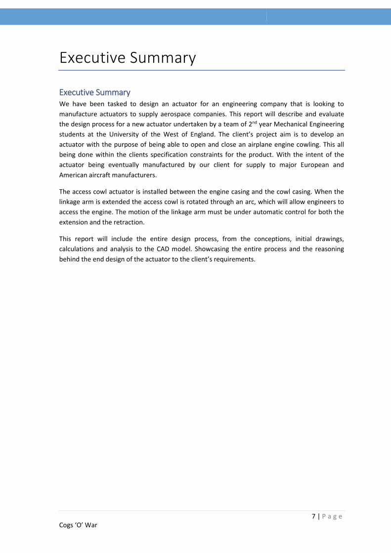
3.3 Z-Shaped Design
The Z-Shaped design is essentially the U-Shaped design however with the addition of another
screw.
Pros
Each screw is taking half of the load, meaning for smaller screw diameters
Because each screw is shorter the bending forces are less.
Cons
Casing and motor housing would be subject to a lot of bending forces from the two
screws pushing against each other.
The motor/casing being in the middle means it may obstruct access into the cowling.
Figure 3 - Z-Shaped Concept Drawing
3.4 Concept Conclusion
We will be going with the U-Shaped design, due to the compact nature of its design and the fact
that spur gears are simpler than the bevel gears required for the 90 degree drive in the L-shaped
design. The motor and screw are parallel in the U-Shaped design, which should make the
gearbox design more straightforward.

16 | P a g e Cogs ‘O’ War
Screw and Gear Selection
4 Screw Selection In order to select which screw would be appropriate we need to consider the three type of
screws used in electric linear actuators.
4.1 Acme Screws
Figure 4 - Acme Thread on Screw
Acme screws have a trapezoidal tooth, as you can see from the image above; this has the
characteristic of being very strong, the screws are available in a large variety of leads and
diameters. The nut is usually made of metal; this will require lubrication to overcome friction
forces. Acme screws are able to operate quietly and are relatively low cost. But due to the
inherent friction between the screw and nut; they can be very inefficient and require a high
motor torque to drive them. But as a result of this friction and a combination of thread
geometry, acme screws limit or eliminate the occurrence of back driving.
Acme screws are good choices in applications that require slow speeds and low duty cycles, this
is due to the wear characteristics of acme nuts being affected by many variables; such as nut
material, environmental factors and stress from the application. This makes it difficult to also
accurately predict the resulting life.

17 | P a g e Cogs ‘O’ War
4.2 Ball Screws
Figure 5 - Ball Screws
Ball screws, are re-circulating ball bearings that fit between the arc shaped screw threads and
corresponding threads in the nut, as show in the picture above. Ball bearings are extremely
efficient in how the forces and the relative motion are transmitted. The thread path of the ball
bearings is a constraint to the maximum speed of the system. Ball screws are readily available in
a variety of diameters, leads and accuracies.
Ball screws are ideal for applications which require high duty cycles, high thrust and high speeds;
this is due to ball screws having higher thrust capabilities, longer service life and higher
efficiency than acme screws. However ball screws, unlike acme screws, can be back driven easily
due to the lack of friction between the balls and threads. They also cost more than acme screws
and can be noisy.
4.3 Roller/Planetary Screws
Figure 6 - Roller/Planetary Screw

18 | P a g e Cogs ‘O’ War
Roller or planetary screws have triangular shaped threads; this then matches up with multiple
threaded rollers in the nut, as shown in the picture above. Due to having multiple rolling
elements in the nut it also for a significant increase in surface contact compared to a ball and
acme screw; these rolling elements provide a highly effective system in transmitting load forces,
better than the ball and acme screw. Roller screws have very high force transmission
capabilities, due to the large surface contact area from the rollers to the screw thread.
Roller or planetary screws are ideal for applications which require high duty cycles, high thrust
and high speeds like the ball screw; on top of that they are long lasting, capable of quick
acceleration and require little maintenance. However like ball screws they can be easily back
driven, and are even more expensive than ball screws.
4.4 Conclusion
We have chosen to go with ball screws, this is due to the fact they have better characteristics
than an acme thread and a much simpler way in which to gear them compared to roller screws,
this results in a cheaper manufacturing cost than what we would have from a roller screws.

19 | P a g e Cogs ‘O’ War
Figure 7 - Spur Gear
Figure 8 - Helical Gear
5 Gear Type Selection In order to start calculating gear sizes and force, we need to decide what type of gear is best for
driving our screw.
5.1 Spur Gears
Spur gears are the most common type of gear. Spur gears have
teeth that run perpendicular to the face of the gear; this means
the tooth contact is mainly rolling, whilst sliding will occur during
engagement and disengagement of the gear. Some noise is
normally produced, but at higher speeds it can reach high levels;
this can become uncomfortable so at high speeds another gear
type would be often more apt.
Spur gears advantages lie in their simplicity in design, economy of
manufacture and maintenance, and an absence of end thrust.
5.2 Helical Gears
Helical Gears have their teeth inclined to the axis of the shafts in
the form of a helix. Helical gears are able to take higher loads than
similarly sized spur gears, due to the extra contact surface from
the tooth face. The motion of helical gears is as a result smoother
and quieter than that of spur gears; these make helical gears more
suited to higher speed operations. Single helical gears impose both
radial loads and thrust loads on their respective bearings and so
would require the use of thrust bearings. When designing the gear,
the angle of the helix on both the gear and the opposing gear must
be the same in magnitude but in opposite direction an example
being a right hand pinion will mesh with a left hand gear.
Helical gear advantages lie in their higher load capacity and a smooth and quiet operation from
low to high speeds compared to spur gears.
5.3 Herringbone Gears
Herring bone gears look like two helical gears placed side by side, as
shown in the picture; they are often called double helicals as a result.
They have all the benefits of helical gears as explained above but due to
the counter-balancing effect of the double helical gears arrangement,
there is no thrust loading on the bearings due to no thrust.
Herringbone gear advantages lie in their higher load capacity and a
smooth and quiet operation from low to high speeds compared to spur
gears. Also they are not affected with thrust forces compared to single
helical gears.
Figure 9 - Herringbone Gear

20 | P a g e Cogs ‘O’ War
Figure 10 - Bevel Gear
5.4 Bevel Gears
Bevel gears have tapered conical teeth which interest the
same tooth geometry; spiral bevel gears are shown in the
picture. Straight bevel gears can be used on shafts at any
angle, with a right angle being the most common. The teeth
on straight bevel gears are tapered in both thickness and
height.
Spiral bevel gears like helical gears compared to spur gears
can take a higher load compared to straight bevel gears.
Bevel gears offer the advantages of being able to change the
axis of rotation, using spur or helical on bevel gears has the
same advantages associated with each.
5.5 Gear Type Conclusion In the design of the gearbox the choice of using spur gears has been decided; this is due to a
combination of factors, such as the ease of design, economy of manufacture and maintenance.

21 | P a g e Cogs ‘O’ War
Actuator Positions
6 Actuator Position Selection When selecting the mounting points for the actuator we used two values to determine the
positions. D1 which allowed us to set the cowling mount was measured from the hinge of the
cowling to the top point of the actuator. Similarly D2 was measured from the top of the engine to
the bottom mount of the actuator.
Once a 2D model was made that could be driven by the two values D1 and D2 we trialled a range
of different positions. To analyse if a position was possible we initially looked at the extended
length compared to the closed length. Through our research it was found that actuators in the
current market were capable of extending to a maximum of 175% of their original length.
6.1 Actuator Positions
Straightaway it was seen there were some areas that would be impossible to use. For example,
Position 4 (Table 2) shows a placement that has very small forces but an extension of 237%
which would be impossible to manufacture. Position 1 (Table 2) has the opposite problem in that
the extension is only 162% but the maximum force is over 18kN.
Table 1 – Values for Actuator Position 1 and 2
Position 1
D1 1220
D2 360
Closed Length 763.54
Extended
Length 1239.77
Extension 162%
Position 2
D1 1120
D2 1431
Closed Length 1106.45
Extended
Length 1909.10
Extension 172%
Figure 12 – Position 1 Open
Figure 11 - Position 1 Closed

22 | P a g e Cogs ‘O’ War
Placing the actuator near to the hinge as shown in Position 3 allows the actuator to be small
which would save on material costs but the force through it would be almost 7kN, leading to the
need for a much larger motor. While it would be possible to produce an actuator at or near this
position it was found that positions closer to Position 2 experienced less load.
Figure 14 - Position 2 Open
Figure 13 - Position 2 Closed
Figure 16 - Position 3 Closed Figure 15 - Position 3 Open

23 | P a g e Cogs ‘O’ War
Table 2 - Values for Actuator Position 3 and 4
Position 3
D1 600
D2 300
Closed Length 515.23
Extended
Length 877.37
Extension 170%
Position 4
D1 1680
D2 1550
Closed Length 865.05
Extended
Length 2050.98
Extension 237%
Figure 18 - Position 4 Closed
Figure 17 - Position 4 Open

24 | P a g e Cogs ‘O’ War
Calculations
7 Euler’s Buckling Force Calculations We had to work out the forces that would be applied to the powerscrew as it was driving the
cowl open. At each position we used in our concept, working from a solidworks drawing we
were able to give ourselves the essential initial values.
Table 3 – Initial Input Values for Euler’s Buckling Equation
Initial input values Angle of cowl opening Ac
Alpha angle acting to the horizontal αh
Horizontal distance from the hinge to the actuator on the cowl
DHorizontal
Constant, when closed it’s the normal distance between the hinge and the centre of
mass.
X1
Figure 19 - Diagram for Initial Input Values for Euler's Buckling Equation
Ac = Angle of cowl open.
αh = Alpha angle acting to
the horizontal.
Dhorizontal = Horizontal
distance from the hinge of
the cowl to the actuator
on the cowl.

25 | P a g e Cogs ‘O’ War
Assuming the hinge on the cowling applies no friction to the movement of the cowling.
1) Vertical component of Force.
Figure 20 - Vertical component of force diagram
2) Cowl Moment Force.
Figure 21 - Cowl moment force diagram
As shown we have 2 forces we need to resolve, the first force is the vertical component of force
which needs to be applied, whilst the 2nd force is the moment of the cowling. Having both of
these forces will give us the force applied on the actuator, with this we can go on to work out
the minimum diameter of the powerscrew under critical stress.
Working out the Cowl moment force, we need to work out what the distance the cowling is
moving through. First we can work out the angles, using the following equations;
𝑨𝟐 = 𝟏𝟖𝟎 − 𝑨𝒄
𝜶 = 𝟗𝟎 − 𝑨𝟐
Now putting this into a diagram we can see we have to resolve some simple trigonometry to give
us the values of D1 and D2.
Fvertical
Dhorizontal
W
D1 D2

26 | P a g e Cogs ‘O’ War
Figure 22 - Diagram showing positions of D1, D2, A2 , 𝜶 and Ac
We worked out the value of X1, this was worked out from equating the centre of mass from an
arc using the following formula. It is also a constant. This is assuming a uniform density of the
cowling material across the arc.
𝑪𝒆𝒏𝒕𝒓𝒆 𝒐𝒇 𝒎𝒂𝒔𝒔 𝒊𝒏 𝒙 𝒂𝒙𝒊𝒔 𝒇𝒐𝒓 𝒂𝒏 𝑨𝒓𝒄 = 𝟐𝒓
𝝅
𝑿𝟏 = 𝟐 × 𝟏𝟓𝟎𝟎𝒎𝒎
𝝅
𝑿𝟏 = 𝟗𝟓𝟓. 𝟒𝒎𝒎
Using this we can put the value of X1 in to give us D1.
𝑫𝟏 = (𝑺𝒊𝒏(𝜶𝒓𝒂𝒅) × 𝑿𝟏)
And we now work out D2.
𝑫𝟐 = 𝒓 × (𝑺𝒊𝒏 (𝑨𝑪𝒐𝒘𝒍 𝑹𝒂𝒅))
We also know that the weight of the cowling is 200kg, provided to us in the brief. We are now
able to calculate the cowling moment at this point. Using the formula;
𝑪𝒐𝒘𝒍𝒊𝒏𝒈 𝑴𝒐𝒎𝒆𝒏𝒕 = 𝑴𝒈 × 𝑫(𝑬𝒙𝒕𝒆𝒏𝒅𝒆𝒅 𝑨𝒄𝒕𝒖𝒂𝒕𝒐𝒓)
This can be written as;
𝑪𝒐𝒘𝒍𝒊𝒏𝒈 𝑴𝒐𝒎𝒆𝒏𝒕 = 𝑾(𝑫𝟏 + 𝑫𝟐)
Now we have the cowling moment we can work out the vertical force;
𝑽𝒆𝒓𝒕𝒊𝒄𝒂𝒍 𝑭𝒐𝒓𝒄𝒆 𝒐𝒏 𝑨𝒄𝒕𝒖𝒂𝒕𝒐𝒓 = 𝑪𝒐𝒘𝒍𝒊𝒏𝒈 𝑴𝒐𝒎𝒆𝒏𝒕
𝑫𝑯𝒐𝒓𝒊𝒛𝒐𝒏𝒕𝒂𝒍

27 | P a g e Cogs ‘O’ War
Finding the angle from;
𝑨𝒏𝒈𝒍𝒆 𝒃𝒆𝒕𝒘𝒆𝒆𝒏 𝒂𝒄𝒕𝒖𝒂𝒕𝒐𝒓 𝒂𝒏𝒅 𝒉𝒐𝒓𝒊𝒛𝒐𝒏𝒕𝒂𝒍 = 𝜶𝒉 ×𝝅
𝟏𝟖𝟎
Now working out the force on the actuator will be simply;
𝑭𝒐𝒓𝒄𝒆 𝒂𝒄𝒕𝒊𝒏𝒈 𝒖𝒑𝒐𝒏 𝑨𝒄𝒕𝒖𝒂𝒕𝒐𝒓 = 𝑽𝒆𝒓𝒕𝒊𝒄𝒂𝒍 𝑭𝒐𝒓𝒄𝒆 𝒐𝒏 𝑨𝒄𝒕𝒖𝒂𝒕𝒐𝒓
𝑺𝒊𝒏(𝑨𝒏𝒈𝒍𝒆 𝒃𝒆𝒕𝒘𝒆𝒆𝒏 𝒂𝒄𝒕𝒖𝒂𝒕𝒐𝒓 𝒂𝒏𝒅 𝒉𝒐𝒓𝒊𝒛𝒐𝒏𝒕𝒂𝒍)
Now that we have the Force acting through the actuator we can work out the forces going
through each point at varying degrees to see which one has the biggest component of force
acting against the actuator.
D1 is the hinge to the top of the actuator
D2 is from the top of the engine to the bottom of the actuator
Table 4 - Force values at points 1 and 2
(1)Point where D1=1220,D2=360 (2)Point where D1=1120,D2=1431
Cowl Angle (Degree)
Force acting upon Actuator (N)
Cowl Angle (Degree)
Force acting upon Actuator (N)
0 18196 0 1805 5 8962 5 1986
10 6439 10 2156 15 5304 15 2320 20 4681 20 2480 25 4315 25 2639 30 4065 30 2796 35 3919 35 2958 40 3835 40 3126 42 3815 42 3197 45 3799 45 3307
Table 5 - Force values at points 3 and 4
(3)Point where D1=600,D2=300 (4)Point where D1=1680,D2=1550
Cowl Angle (Degree)
Force acting upon Actuator (N)
Cowl Angle (Degree)
Force acting upon Actuator (N)
0 2862 0 1530 5 4208 5 1546
10 4523 10 1750 15 4841 15 1831 20 5155 20 1901 25 5483 25 1962 30 5799 30 2017 35 6162 35 2069 40 6553 40 2122
42 6720 42 2143 45 6988 45 2176

28 | P a g e Cogs ‘O’ War
0
1,000
2,000
3,000
4,000
5,000
6,000
7,000
8,000
0 5 10 15 20 25 30 35 40 45 50
Forc
e (
N)
Cowl Angle (Degree)
(3)Point where D1=600, D2=300
0
500
1,000
1,500
2,000
2,500
3,000
3,500
0 5 10 15 20 25 30 35 40 45 50
Forc
e (
N)
Cowl Angle (Degree)
(2)Point where D1=1120, D2=1431
0
5,000
10,000
15,000
20,000
0 5 10 15 20 25 30 35 40 45 50
Forc
e (
N)
Cowl Angle (Degree)
(1)Point where D1=1220, D2= 360
Figure 25 - Graph showing at point 1, Force Vs Cowl Angle
Figure 24 - Graph showing at point 2, Force Vs Cowl Angle
Figure 23 - Graph showing at point 3, Force Vs Cowl Angle

29 | P a g e Cogs ‘O’ War
Figure 26 - Graph showing at point 4, Force Vs Cowl Angle
Having looked at potential concepts for an actuator design, we now need to consider the most
logical position for the actuator to be fitted. Now we have the data from 4 different points we
can compare which one is best. This was done by considering factors such as;
7.1 Extension of Powerscrew
An optimal position would have a minimal extension of the actuator, as this would reduce
the forces of buckling onto the shaft. However normally when you achieve a small
extension the position will be located as such that a large force and torque will be needed
to overcome the force of the cowl.
7.2 Force acting upon the actuator
An optimal position would have the smallest force acting upon the actuator; this means less
stress acting upon the actuator. Having a smaller force would allow for a smaller driving
force from the motor and a smaller diameter of powerscrew. Having minimal force acting
upon the actuator is advantageous as we can save weight from having a smaller motor and
from having a smaller powerscrew (In terms of diameter).
7.3 Non-Obstructing
An optimal position would take into consideration the position of the engine as to not
interfere with it.
Whilst the last graph (4) has the smallest acting force on it throughout, we wouldn’t be able to
fit an actuator inside the cowling large enough that could extend the full way to 45 degrees at
this point. As such we have gone with position (2) which offers the second smallest force, but it
is a small enough distance of movement that we can design an actuator to fit inside the cowling
and extend enough to move it through 45 degrees of movement.
0
500
1,000
1,500
2,000
2,500
0 5 10 15 20 25 30 35 40 45 50
Forc
e (
N)
Cowl Angle (Degree)
(4)Point where D1=1680, D2=1550

30 | P a g e Cogs ‘O’ War
Now that we have selected the optimum position, we need to consider what Factor of Safety
would make the most sense for the screw. To do this we have looked at 2 sources for
components and decided a factor of safety of 1.5 for an aerospace component for a design
makes the most sense. Both the sources are referenced.
Using this we can now continue with the diameter calculations for the screw.
𝑪𝒓𝒊𝒕𝒊𝒄𝒂𝒍 𝑭𝒐𝒓𝒄𝒆 𝒖𝒑𝒐𝒏 𝑨𝒄𝒕𝒖𝒂𝒕𝒐𝒓
= 𝑭𝒐𝒓𝒄𝒆 𝒂𝒄𝒕𝒊𝒏𝒈 𝒖𝒑𝒐𝒏 𝑨𝒄𝒕𝒖𝒂𝒕𝒐𝒓 × 𝑭𝒂𝒄𝒕𝒐𝒓 𝒐𝒇 𝑺𝒂𝒇𝒆𝒕𝒚(𝟏. 𝟓)
Having worked out the Critical force upon the actuator with a relationship to the factor of safety,
we can now look to add in the efficiency rating to get the total force on the actuator.
𝑻𝒐𝒕𝒂𝒍 𝑭𝒐𝒓𝒄𝒆 = 𝑪𝒓𝒊𝒕𝒊𝒄𝒂𝒍 𝑭𝒐𝒓𝒄𝒆 𝒖𝒑𝒐𝒏 𝑨𝒄𝒕𝒖𝒂𝒕𝒐𝒓 × 𝑬𝒇𝒇𝒊𝒄𝒆𝒏𝒄𝒚(𝟗𝟎%)
Now with all this we can calculate the minimum required diameter of the screw that will be
necessary to support the load.
Table 6 - Input values for the Diameter of the screw
Values used to calculate the minimum diameter of the screw
Young’s Modulus of chosen metal E Column effective length factor K
Actuator Length (From Solid works) L
This is worked out from the following equation;
𝑫𝒊𝒂𝒎𝒆𝒕𝒆𝒓 = √𝑭𝒄𝒓 × (𝑲𝑳)𝟐 × 𝟔𝟒
𝝅𝟑 × 𝑬
𝟒
Now that we have the minimum diameter needed for the screw, we can proceed to select what
screw size we want to use, obviously it would make sense to select a size that is recognised and
a standard in manufacturing.
We have selected an outer screw diameter of 25mm, as this is over the minimum diameter we
calculated from Euler’s buckling equation; it is also an industrial standard size and will allow for
easier manufacturing for the client.
The total length of the screw is taken from the cad drawing, along with the extension of the
actuator.

31 | P a g e Cogs ‘O’ War
-5
0
5
10
15
20
25
30
35
40
0 5 10 15 20 25 30 35
Ve
loci
ty
Time
8 Screw Opening Timing Calculation The design brief specified a time of at least 30 seconds for the cowl to travel from its closed
position to its position of maximum extension. We drew up some rough profiles of acceleration,
constant velocity and deceleration.
The four profiles we tester were 5 seconds of acceleration followed by 20 seconds of constant
velocity and 5 seconds of deceleration, 10 seconds of acceleration followed by 10 seconds of
constant velocity and 10 seconds of deceleration, 15 seconds of acceleration 15 seconds of
deceleration and lastly 7.5 seconds of acceleration followed by 15 seconds of constant velocity
and 7.5 seconds of deceleration. 803mm has to be travelled linearly in the 30 seconds, and
knowing this we were able to find the maximum velocities for each profile and taking all
accelerations and decelerations to be constant the accelerations were calculated. The middle
section of constant velocity was changed for each profile to provide us with more manageable
accelerations and as all were reduced it meant that all profiles still fitted within the 30 second
time frame (28.62s, 29.10s, 30.00s, and 30.00s).
Using the accelerations and times for acceleration, constant velocity and deceleration the linear
velocity of the ball screw was calculated using 𝑣 = 𝑢 + 𝑎𝑡. Once this was calculated the opening
at each time was calculated by current distance=previous distance + velocity*time increment.
Using our lead value of 5mm the RPM of the ball screw was calculated by (linear
velocity/lead)*60. We chose the profile of 7.5s acceleration 15s of constant velocity and 7.5s to
decelerate. We chose this due to its relatively low acceleration of 4.8mm/s2 and also its
maximum rotational speed of 432RPM which is lower than the critical RPM of the ball screw.
Those profiles that have a lower acceleration have a higher max RPM and vice versa. The profiles
of 15s acceleration and 15 seconds of deceleration failed our selection because its maximum
rotation speed of 642.6RPM was higher than the ball screws critical rotational speed. The other
two profiles were felt to have to high accelerations which would result in higher torques and
thus were not chosen.
This is our graph of velocity against time for our chosen profile. According to Thompson BSA the
critical rotational speed for a ball screw with our length of fixed free powerscrew and diameter
should be around 475RPM.
Figure 27 - Graph showing Velocity vs Time

32 | P a g e Cogs ‘O’ War
9 Torque Calculations Now that we have calculated Euler’s buckling equation for the screw, and as a result have the
minimum diameter of the screw along with the length of extension of the screw, we can start to
equate the driving torque needed to overcome the force; as previously calculated for the
actuator position we are going with.
This table shows the forces acting upon the
actuator at each angle from the load of the cowling. A
factor of safety of 1.5 has been applied onto the force for
the torque calculations.
9.1 Driving Torque The driving torque is the torque needed to overcome the friction of the screw along with the
load applied from the cowling at any moment along its varying degrees of opening.
The formula for total driving torque in our system is;
𝑇𝑑 =𝐹 × 𝑃ℎ
2𝜋 × 𝜂1
Where
Td = Driving torque (Nm)
F = Axial load (N)
Ph = Lead (m)
η1 = Normal efficiency
Before we can calculate the driving torque we need to decide on a range of screw leads. These
have been taken from industrial standard grades, with 5mm being the smallest standard. Our
range will be 5, 10 and 15mm leads.
Opening Force (N) W/FOS @1.5
0 1,805 2707.5
5 1986 2979
10 2156 3234
15 2320 3480
20 2480 3720
25 2639 3958.5
30 2796 4194
35 2958 4437
39.165 3098 4647
40 3126 4689
40.327 3138.655 4707.9825
41.232 3146.677 4720.0155
41.877 3193.124 4789.686
42 3197 4795.5
42.261 3206.772 4810.158
42.38 3211.019 4816.5285
45 3307 4960.5
Table 7 - Force acting upon actuator through cowl opening angle

33 | P a g e Cogs ‘O’ War
The lead angle was also calculated from the lead, as this value will be used for designing the
screw in schematics.
𝐿𝑒𝑎𝑑 𝐴𝑛𝑔𝑙𝑒 (𝑅𝑎𝑑𝑠) = 𝑎𝑟𝑐𝑡𝑎𝑛 (𝐿𝑒𝑎𝑑
𝜋 × 𝑑𝑚)
dm = Mean diameter of the helix
In this case the mean diameter of the helix is taken as the inside diameter of the screw, that
being 23mm.
Inputting the following equation for each lead we get the following table of driving torques;
Lead (Ph) Lead (Ph) Lead (Ph)
mm cm mm cm mm cm
5 0.5 10 1 15 1.5
Normal Efficiency (η1) Normal Efficiency (η1) Normal Efficiency (η1)
0.87 0.94 0.95
Lead Angle Lead Angle Lead Angle
Radians Degrees Radians Degrees Radians Degrees
0.06909 3.95843 0.13752 7.87943 0.20469 11.7277
Opening (deg) Torque (Nm) Opening (deg)
Torque (Nm) Opening (deg)
Torque (Nm)
0 2.476505796 0 4.584170302 0 6.803873817
5 2.724842388 5 5.043857186 5 7.486145928
10 2.958086701 10 5.475607297 10 8.126953989
15 3.183098862 15 5.89211917 15 8.745145294
20 3.402622921 20 6.298472216 20 9.348258763
25 3.620774955 25 6.702285556 25 9.947602772
30 3.836182939 30 7.101019482 30 10.53940786
35 4.058451049 35 7.512451941 35 11.15006025
40 4.288951311 40 7.93912264 40 11.78332939
42 4.386365113 42 8.119441804 42 12.05096099
45 4.537287903 45 8.398809523 45 12.4656015
Table 8 - Values of Lead, to calculate the driving torque

34 | P a g e Cogs ‘O’ War
9.2 Back driving Torque
The back driving torque is the torque required to move the actuator in the opposite direction, in
our case the back driving torque should be less
𝑇𝑏 = 𝐹 × 𝑃ℎ × 𝜂2
2𝜋
The table below shows the back driving torque calculated;
Lead (Ph) Lead (Ph) Lead (Ph)
mm cm mm cm mm cm
5 0.5 10 1 15 1.5
Normal Efficiency (η1) Normal Efficiency (η1) Normal Efficiency (η1)
0.87 0.94 0.95
Lead Angle Lead Angle Lead Angle
Radians Degrees Radians Degrees Radians Degrees
0.06909 3.95843 0.13752 7.87943 0.20469 11.7277
Opening (deg) Torque (Nm) Opening (deg)
Torque (Nm) Opening (deg)
Torque (Nm)
0 1.874467237 0 4.050572879 0 6.14049612
5 2.062433203 5 4.456752209 5 6.7562467
10 2.238975824 10 4.838246608 10 7.334575975
15 2.409287529 15 5.206276498 15 7.892493628
20 2.575445289 20 5.56533005 20 8.436803533
0
0.5
1
1.5
2
2.5
3
3.5
4
4.5
5
0 10 20 30 40 50
Dri
vin
g To
rqu
e(N
m)
Opening Angle (Degrees)
Driving Torque vs Opening Angle (Nm)
Torque (Nm)
Opening (deg)
Torque (Nm)
0 2.476505796
5 2.724842388
10 2.958086701
15 3.183098862
20 3.402622921
25 3.620774955
30 3.836182939
35 4.058451049
39.165 4.250534601
40 4.288951311
40.327 4.306314292
41.232 4.31732068
41.877 4.381047142
42 4.386365113
42.261 4.399772545
42.38 4.405599536
45 4.537287903
Table 9 - Values of torque through opening degree at Lead of 5mm

35 | P a g e Cogs ‘O’ War
25 2.740564564 25 5.922139517 25 8.977711502
30 2.903606866 30 6.274460814 30 9.511815596
35 3.071841599 35 6.638002535 35 10.06292938
40 3.246307247 40 7.015008765 40 10.63445478
42 3.320039754 42 7.174338778 42 10.8759923
45 3.434273214 45 7.421188095 45 11.25020536
Table 10 - Values of Lead, to calculate the back driving torque
As shown from both tables is it clear that the best lead would be 5mm, this is due to it being the
lowest driving torque and back driving torque. This means we are going to be using a 5mm lead
for our screw.
9.3 Drag Torque
Is the torque required to drive the actuator when subject to zero load forces, this is taken from
an opening angle of 0 from the driving torque table. This gives us a Drag Torque of 2.47650Nm.
9.4 Max Torque The maximum torque is simply the sum of the acceleration torque, the frictional torque, the
driving torque and the centre of mass torque of the cowling. The back driving torque does not
need to be considered because it is always smaller than the driving torque.
Acceleration Torque 1.437 Nm
Frictional Torque 0.486 Nm
Driving Torque 4.406 Nm
Centre of Mass Torque 8.840 Nm
Total Torque 15.171 Nm
These are from calculations done in our spreadsheet.

36 | P a g e Cogs ‘O’ War
10 Motor Selection From the project brief we were given some conditions to select the motor. These were:
110 Vots
50/60 Hz
Single Phase
The final condition would be imposed by use, and this would be the torque required for the
power screw to open in the allotted time. This torque was calculated from speed required from
the power screw to open in 30 seconds and is displayed on the V.T Angle sheet on the
calculations spreadsheet.
𝑃𝑜𝑤𝑒𝑟 = 𝑡𝑜𝑟𝑞𝑢𝑒 × 𝑅𝑃𝑀
60× 2𝜋
𝑃𝑜𝑤𝑒𝑟 = 15.17092 × 432
60 × 2𝜋
𝑃𝑜𝑤𝑒𝑟 𝑟𝑒𝑞𝑢𝑖𝑟𝑒𝑑 𝑓𝑟𝑜𝑚 𝑚𝑜𝑡𝑜𝑟 = 686.316 𝑊𝑎𝑡𝑡𝑠
1 𝐻𝑃 = 745.700 𝑊𝑎𝑡𝑡𝑠
From these we researched possible motors and decided to use the Worldwide Electric GP Motor.
This motor satisfies all of the requirements specified above. It is convenient for us that the
maximum power required from the motor is just below that of 1 HP. This made it easier to
search for the correct motor and also allow us to choose a smaller motor still capable of 110V
and have a single phase.
Worldwide Electric GP Motor NT1-18-56CB, TEFC,
REM-C, 1 PH, 56C, 1 HP, 6.8 FLA, Less Overload
Figure 28 - Electric GP Motor

37 | P a g e Cogs ‘O’ War
11 Gear Calculations
11.1 Gear Size Calculations:
Having chosen spear gears as mentioned previously, we next needed to select the size and
number of teeth of the gears in our system. We then need to confirm these sizes are acceptable
using various stress equations to make sure the gears can withstand the forces they will
experience.
To calculate the gear size we used the following equations;
𝑒 = 𝑑1
2
𝑑22
e = speed last gear/ speed first gear
Where e is the ratio of speeds of the gears. From our previous calculations and motor selection,
we know that the maximum speed of the motor is 2850 RPM, and the speed required for the
power screw is 432 RPM. Therefore:
Speed of the first gear = 2850 rpm
Speed of the last gear = 432 rpm
This means;
𝑒 = 432
2850
e = 0.15158
Using this we can work out the corresponding d2 value of the gear
𝑑2 = ((𝑑1
2)
𝑒)
0.5
The diameter of the gear connected to the motor (𝑑1) had to be a minimum of 16 mm, as the
shaft on the motor had a diameter of 15.875 mm. Realistically this is still far too small, but we
used this as a starting point to calculate the diameter for the second gear (𝑑2) as shown on the
Gear Size sheet in our Cowl Calculations Spreadsheet. The above equation gave us a list of 𝑑2
diameters corresponding to 𝑑1diameters in 0.5 mm increments. Note these diameters are the
pitch diameters.

38 | P a g e Cogs ‘O’ War
The module number, m, was recommended to be between the value of 2 and 6. This number
simply represents the relative size of the gears to the number of teeth on those gears, given by:
𝑚 = 𝑝𝑖𝑡𝑐ℎ 𝑑𝑖𝑎𝑚𝑒𝑡𝑒𝑟 (𝑚𝑚)
𝑁𝑜.𝑡𝑒𝑒𝑡ℎ
The table on below is a small extract from the large table on the Gear Size sheet. You can see
that each pair of diameters, have a matching pair of number of teeth, for each module number.
For example highlighted in yellow, the diameters 33.50 mm and 86.04 mm have 11.17 and 28.68
teeth respectively (having chosen a module number of 3). These numbers are however
unfeasible as it would be impossible for the gear to work without a whole number of teeth. Also
manufacturing the gears to strange diameters is illogical and only complicates the process
further.
Diameter (mm) m = 2 m = 2.5 m = 3.0
d1 d2 N1 N2 N1 N2 N1 N2
33.50 86.04 16.75 43.02 13.40 34.42 11.17 28.68
34.00 87.33 17.00 43.66 13.60 34.93 11.33 29.11
34.50 88.61 17.25 44.31 13.80 35.45 11.50 29.54
35.00 89.90 17.50 44.95 14.00 35.96 11.67 29.97
35.50 91.18 17.75 45.59 14.20 36.47 11.83 30.39
36.00 92.47 18.00 46.23 14.40 36.99 12.00 30.82
36.50 93.75 18.25 46.88 14.60 37.50 12.17 31.25
37.00 95.03 18.50 47.52 14.80 38.01 12.33 31.68 Table 11 - Table showing selected values as highlighted
The selection of the gear sizes came down to out knowledge as well as logic. Having a gear
manufactured to 0.01 of a mm was unnecessary, especially if it required having a number of
teeth that was not a whole number. We chose the diameters (highlighted in green) of 35 mm for
𝑑1and 90 mm for 𝑑2. Note that for 𝑑2 we have rounded up from 89.90 mm. These values were
selected as they have the nearest whole values, which correspond to the nearest whole values
of teeth. Looking over to the number of teeth, you can see 𝑑1 and 𝑑2 have teeth 14.00 and
35.96 respectively. This is extremely close to a whole number of teeth, and therefore rounding
has very little effect on the equations that follow. The module number remained between 2 and
6, meaning that our gears still satisfied the criteria.
Diameter (pitch) (m) Number of teeth Module
Gear 1 0.035 14 2.5 Gear 2 0.090 36 2.5
Table 12 - Showing selected Gear Values

39 | P a g e Cogs ‘O’ War
11.2 Gear Stresses Having calculated and selected the diameters for our gears we can now proceed to calculate the
respected forces that will be acting against the gears, this will determine if the material we’ve
selected is strong enough for the gears or if we need to reconsider the gear size. We will
calculate the Lewis Bending Stress, the AGMA Stress and the Bending Factor of Safety.
11.2.1 Lewis Bending Stress
We use Lewis Bending Equation to
find out the resultant bending force
acting on each gear tooth. It is
assumed that only one pair of teeth
are in contact. This is from the
following formula;
𝜎 = 𝐾𝑣 𝑊𝑡
𝐹𝑚𝑌
𝐿𝑒𝑤𝑖𝑠 𝐵𝑒𝑛𝑑𝑖𝑛𝑔 𝑆𝑡𝑟𝑒𝑠𝑠 = 𝐷𝑦𝑛𝑎𝑚𝑖𝑐 𝐹𝑎𝑐𝑡𝑜𝑟 × 𝑇𝑎𝑛𝑔𝑒𝑛𝑡𝑖𝑎𝑙 𝑇𝑟𝑎𝑛𝑠𝑚𝑖𝑡𝑡𝑒𝑑 𝐿𝑜𝑎𝑑
𝐹𝑎𝑐𝑒 𝑊𝑖𝑑𝑡ℎ × 𝐶𝑖𝑟𝑐𝑢𝑙𝑎𝑟 𝑃𝑖𝑡𝑐ℎ × 𝐿𝑒𝑤𝑖𝑠 𝐹𝑜𝑟𝑚 𝐹𝑎𝑐𝑡𝑜𝑟
The first thing we can work out is the Tangential transmitted load on each gear, 𝑊𝑡 , this is done
using the following equation:
𝑇𝑎𝑛𝑔𝑒𝑛𝑡𝑖𝑎𝑙 𝑡𝑟𝑎𝑛𝑠𝑚𝑖𝑡𝑡𝑒𝑑 𝑙𝑜𝑎𝑑, 𝑊𝑡 (𝑁) = 2 × 𝑇𝑜𝑟𝑞𝑢𝑒 𝑖𝑛 𝑃𝑜𝑤𝑒𝑟𝑠𝑐𝑟𝑒𝑤
𝐺𝑒𝑎𝑟 𝑃𝑖𝑡𝑐ℎ 𝐷𝑖𝑎𝑚𝑒𝑡𝑒𝑟
The maximum torque in the powerscrew is taken from the V.T angle sheet in the Cowl
Calculations Spreadsheet, and is given as 15.171 Nm.
Using this we obtain the following load values for each subsequent gear.
The dynamic factor Kv accounts for internally generated gear tooth loads which are induced by non-uniform meshing action (transmission error) of gear teeth. If the actual dynamic tooth loads are known from a comprehensive dynamic analysis, or are determined experimentally, the dynamic factor is then calculated from:
𝐾𝑣 =6.1 + 𝑉
6.1
Where 𝑉 = 𝑟𝑎𝑑𝑖𝑢𝑠 × 𝑎𝑛𝑔𝑢𝑙𝑎𝑟 𝑣𝑒𝑙𝑜𝑐𝑖𝑡𝑦
Tangential transmitted load (N)
Wt 1 866.910
Wt 2 337.131
Table 13 - Values for Tangential transmitted load for each gear
Figure 29 - Diagram showing values on gear tooth

40 | P a g e Cogs ‘O’ War
This is taken as 6.1 because the material we are using will be cut or milled.
The values for 𝑉 and Kv are as follow:
𝑽 Dynamic Factor
𝑽𝟏 0.000560 Kv 1 1.0001836 𝑽𝟐 0.001440 Kv 2 1.0004721
Table 14 - Showing values for V and Kv
Now we need the Lewis Form Factor Y, this is taken from the table below and is related to the number of teeth on your gear.
This table is taken from the notes regarding gear
calculations. Note that for 36 teeth we took an
average between 34 and 38 teeth from the table.
The face width F was originally given a value of 15 mm. This is the width of the gear, and the
width of the teeth in contact with the connecting gear. This value can be altered if necessary, for
example if the factor of safety is too low, then by widening the gear the stresses decrease, and
hence making the gears safer.
Now we have all the values we can work out the Bending stress for each gear, the table below
shows the results;
Lewis Bending Equation Factor of Safety
σ 1 (MPa) 5.96 44.5
σ 2 (MPa) 0.66 401.0
Table 16 - Value of Bending Stresses and Factors of Safety for each Gear
The factor of safety is the yield tensile strength, divided by the maximum stress experienced.
The material we have selected for the gear is AISI Carbon Steel, Annealed. This material has a
tensile strength of 265 MPa, and our first gear is undergoing less than 6 MPa. This shows that
Lewis Form Factor, Y
No. teeth Y
N1 14 0.277
N2 36 0.378
Table 15 - Showing Lewis Form Factor for each Gear Teeth No.
Figure 30 - Data sheet for Lewis Form Factor
41 | P a g e Cogs ‘O’ War
not only is the material selection well within the factor of safety, but that the dimensions of the
gear also hold to be correct for this application.
11.2.2 AGMA Stress Equation
Two fundamental equations are used in the AGMA methodology, one for bending stress and the
other for contract stress. Here we will be concerned with the bending stress. The equation is as
follows:
𝜎 = 𝑊𝑡 𝐾𝑜 𝐾𝑣 𝐾𝑠 1
𝐹𝑚
𝐾𝐻 𝐾𝐵
𝑌𝐽
𝑊𝑡 = tangential transmitted load (N)
𝐾𝑜 = overload factor
𝐾𝑣 = dynamic factor
𝐾𝑠 = size factor
𝐹 = face width of the gear
𝑚 = module
𝐾𝐻 = load-distribution factor
𝐾𝐵 = rim-thickness factor
𝑌𝐽 = geometry factor
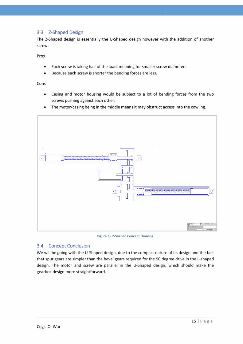
Overload factor 𝐾𝑜 is used to make allowance for all externally applied loads in excess of the nominal tangential load(𝑊𝑡). In determining the overload factor, consideration should be given to prime movers and driven equipment, individually or in combination. There are many possible sources of overload which should be considered. Some of these are: system vibrations, acceleration torques, over speeds, variations in system operation, split path load sharing among multiple prime movers, and changes in process load conditions.
We assume the system to undergo uniform, light shock, giving a value of 1.25.
Power Source Uniform Moderate shock Heavy shock
Uniform 1.00 1.25 1.75 Light shock 1.25 1.50 2.00 Medium shock 1.50 1.75 2.25
Table 17 - Grid for displaying Ko Values
Dynamic factor 𝐾𝑣, is derived from the Gear Quality Index Number (Qv), which is given by the
intended application of the system. The Qv we will use is a value of 6.
𝐾𝑣 = (𝐴 + √200𝑉
𝐴)
𝐵
Where
𝐴 = 50 + 56(1 − 𝐵)

42 | P a g e Cogs ‘O’ War
1.5
1.6
1.7
1.8
1.9
2
2.1
0 100 200 300 400 500 600
KH
Face Width (mm)
Load Distribution Factor
𝐵 = 0.25(12 − 𝑄𝑣)23
𝑉 = (𝐴 + (𝑄𝑣 − 3))2
200
Substituting 𝑄𝑣 = 6 , we get the follow values for 𝐴, 𝐵, 𝑉𝑎𝑛𝑑 𝐾𝑣:
𝑲𝒗 1.81
𝑨 59.77
𝑩 0.83
𝑸𝒗 6.00
𝑽 19.70
Table 18 - Summary table of values for Gear Stress Equation
The size factor, 𝐾𝑠 reflects non-uniformity of material properties die to its size. It depends upon:
Tooth size
Diameter
Ratio of tooth size to diameter
Face width
Area of stress pattern
Ratio of case depth to tooth size
Hardenability and heat treatment
The equation is given as 𝐾𝑠 = 1.192 (𝐹√𝑌
𝑃)
But with the condition that if 𝐾𝑠 < 1, use 𝐾𝑠 = 1. Using F as the face width, Y as the Lewis Factor
and P as 1/module. Calculating 𝐾𝑠 gave us a value of well below 1 and so we used 𝐾𝑠 = 1.
The load distribution factor KH modifies the stress equation to reflect non-uniform distribution
of the load around the line on contact. As the face width is less than 50 mm, we take KH as 1.6.
Table 19 - Graph showing the Load Distribution Factor

43 | P a g e Cogs ‘O’ War
When rim-thickness factor is not sufficient to provide full support for the tooth root, the location
for bending fatigue failure may be though the gear rim rather than the tooth fillet.
𝐾𝐵 = 1.6 ln2.242
𝑚𝐵
𝑚𝐵 = 𝑡𝑅
ℎ𝑡
Gear 1 Gear 2
𝒕𝑹 0.012 0.027
𝒉𝒕 0.006 0.006
𝒎𝑩 2.000 4.500
KB 1 1
Table 20 - Values of tR, ht, mB and KB for AGMA Stress Equation
We are given the condition that if 𝑚𝐵 > 1.2, then to use KB as 1.
The geometry factor YJ is read off the
graph to the right:
Giving us values 0.24 and 0.38 for
gears 1 and 2 respectively.
AGMA Stress Equation Factor of Safety
σ 1 (MPa) 26.44 10.02
σ 2 (MPa) 6.50 40.80
Table 21 - AGMA Stress Equations calculated for Gear 1 and 2
Figure 31 - Diagram showing ht and tR
Figure 32 - Graph showing Geometry Factors YJ for Spur Gears

44 | P a g e Cogs ‘O’ War
11.2.3 Bending Factor of Safety
The final part of the AGMA methodology is the bending stress equation given by:
𝑆𝐹 = (𝑆𝑡 𝑌𝑁 ÷ (𝑌𝜃 𝑌𝑍)
𝜎
𝑆𝑡 = bending strength
𝑌𝑁 = stress cycle factor
𝑌𝜃 = temperature factor
𝑌𝑍 = reliability factor
𝜎 = AGMA stress
The bending strength is given as the hardness of the material in Brinell (HB). The given hardness
of our material is 110 Vickers (HV). The conversion from HV to HB is simply 110 HV = 105 HV.
The stress cycle factor is used
to modify the gear strength
for a life other than 107
cycles. The factor is read off
the graph below. First of all
we must calculate the
number of operation cycles
the system is expected to
undergo.
Using the life calculations we
get a life of 6.416 hours of
operation.
This equates to 770 complete
(up and down) operations.
The required number of
operations is 400. (20,000
flight hours, 1 operation every 50 flight hours). Reading off the graph we get a stress cycle factor
or 1.6.
The temperature factor 𝑌𝜃 is given to us a value of 1.0.
The reliability factor 𝑌𝑍 accounts for the effect of the statistical distribution of material fatigue
failures. A YZ factor of 1.00 was calculated.
Reliability 𝒀𝒁
0.9999 1.50 0.999 1.25 0.99 1.00 0.90 0.85 0.50 0.70
Table 22 - Reliability values
Figure 33 - Graph showing Stress Cycle Factor YN

45 | P a g e Cogs ‘O’ War
Bending Factor of Safety
Gear 1 4.92
Gear 2 25.87
Table 23 - Bending Factor of Safety
11.3 Gear Calculation Conclusion:
Having gone through the calculations above, the dimensions of the gears have confirmed to be
able to withstand the stresses within the system.
Note: After having calculated the gear sizes we realised that the size of the motor meant we
had a large distance between the centre of the motor and powerscrew shaft. This distance was
greater than the distance provided by our gears (see below).
Figure 34 - Gear Position Setups
Figure 1 shows our original two gear configuration, as you can see the motor is too large to fit
the gear and power screw shaft. Instead of changing all of the calculations for larger gears, we
simply added another gear in between the two previous gears (figure 2). This allows us more
room between the motor and the power screw for casing etc. The third gear is exactly the same
as the second gear, meaning the equations still stand for these gears.
Gear 1 Gear 2 Gear 3
Pitch Diameter (m) 0.035 0.090 0.090 Outside Diameter (m) 0.043 0.095 0.095 Root Diameter (m) 0.030 0.084 0.084 No. Teeth 14 36 36
Table 24 - Final Gear Dimensions

46 | P a g e Cogs ‘O’ War
12 Mounting Calculations We have decided to use a pin joint to attach the actuator to the cowling and engine casing, this
will allow us the freedom of movement we need and secure it.
𝑆𝑡𝑟𝑒𝑠𝑠, 𝜎 = 𝐹𝑜𝑟𝑐𝑒
𝐴𝑟𝑒𝑎
The maximum force on the actuator = 4960 N (from the Load Torque sheet). Because there are
two pin joints, this force is spread between them, and therefore divided by two.
We know that the Tensile Yield Stress of our material, AISI 1020 Carbon Steel Annealed is 265
MPa. We can therefore rearrange the equation to give us the required area.
𝐴𝑟𝑒𝑎 = 𝐹𝑜𝑟𝑐𝑒
𝑇𝑒𝑛𝑠𝑖𝑙𝑒 𝑆𝑡𝑟𝑒𝑠𝑠
𝐴𝑟𝑒𝑎 = 4960 ÷ 2
265 × 106
Therefore the minimum area is given as:
𝐴𝑟𝑒𝑎 = 9.358 × 10⁻⁶ 𝑚2
𝐿𝑒𝑛𝑔𝑡ℎ 𝑜𝑓 𝑒𝑎𝑐ℎ 𝑠𝑖𝑑𝑒 = 0.00306 m
𝑀𝑖𝑛𝑖𝑚𝑢𝑚 𝑙𝑒𝑛𝑔𝑡ℎ 𝑜𝑓 𝑒𝑎𝑐ℎ 𝑠𝑖𝑑𝑒 = 3.1 𝑚𝑚
A size of 3.1 mm for each side of the pin joints is unrealistic, so we decided to go with a length of
15 mm for each side. The pin can also have a diameter of 20mm, which again is well within the
safety factor of our material.
Figure 35 - Pin Joint Size Diagram

47 | P a g e Cogs ‘O’ War
13 Bearing Calculations
13.1 Thrust Bearings
Able to support large axial loads, cylindrical thrust roller bearings are cheap and require little
axial space. However, when operating near their load limit or with a high duty cycle they tend to
wear due to the differences in radial speed. Our design will have neither of these so they’re
suitable for use.
13.2 Ball Bearings
Ball bearings are simpler and more reliable than cylindrical thrust bearings; also, the shafts will
be subjected to almost no axial load that single row radial bearings can be susceptible to.
As there is already a wealth of information about bearings online, this calculator provided by SKF was used to decide on suitable bearings for use inside the gearbox;
To calculate the radial forces produced by the motor this equation was used; 𝑀×𝐹
𝑅
This returned a value of 420 newtons which is an acceptable level compared to the load ratings
of the selected gears
Bearing 1 was the most important choice due to the fact that it would have to support the entire
axial load. Using Fa (axial load) as 5kN and an ni (maximum inner ring rotational speed) of
430rpm the calculator returned a basic rating life (L10h) of 8284.8 hours for a correctly sized
(25mm internal) thrust bearing.
Bearing 2 also had an internal dimension of 25mm but this was chosen to be a deep groove ball
bearing as it would not be placed under the same axial force as bearing 1, using the same
M = Torque (Nm) F = Load connection factor (1.25 for our gears) R = Radius (m)
Figure 36 - Bearing Layout

48 | P a g e Cogs ‘O’ War
calculator returned an L10h of 1668.3 hours which is easily below the required L10h of 66.7
hours.
Used on both ends of the middle shaft was bearing 4, once again a deep groove ball bearing. The
main difference between this and bearing 2 is this has a 20mm internal diameter as opposed to
25mm. This was done as it’s easier to machine onto a shoulder onto the shaft than use a sleeve
on the shaft to accommodate the bearing.
The final bearing, number 3, was chosen to fit onto the 16mm shaft built into the motor. The
best available size was a 12mm deep groove ball bearing which returned an L10h of 902.5 hours.

49 | P a g e Cogs ‘O’ War
14 Actuator Lifespan Calculations Under the requirement specification the actuator needed to be able to last a minimum 20000
flight hours or 400 operations (up and down). Below is the life calculation used to work out the
lifespan of the actuator.
𝐿ℎ = 106
60 × 𝑁𝑚(
𝐶
𝑃𝑚 × 𝐹𝑤)
3
Lh = Life Hours
Nm= Average revolutions per operation
C= Basic Static Load
Pm = Average axial load
Fw = Service Factor
Input Variables
Nm=324 (810mm extension/5mm lead = 162 revolutions) 324 as revolutions for both opening
and closing.
C= 1805N
Pm=2779N
Fw=1.3
A service factor of 1.3 was taken from the below ranges, we felt 1.2 was still classed as a smooth
operation so we went for 1.3. As we felt it was the most suitable for the conditions of our
operation.
1.0→1.2 For a smooth operation.
1.2→1.5 For a normal operation.
1.5→2.0 For an operation with vibrations or shocks.
This gives us a life of 6.416 hours of operation.
This equates to 770 complete (up and down) operations.
The required number of operations is 400. (20000 flight hours, 1 operation every 50 flight
hours). This means we are well within the lifespan requirements that the client wishes.
Whilst this is a theoretical calculation of the lifespan, to get the true lifespan of the product we
would need to conduct tests with a prototype batch.

50 | P a g e Cogs ‘O’ War
15 Lubrication Many parameters must be considered when selecting ball screw lubrication. The correctly
selected lubricant minimises friction, reduces torque, increases the screw’s efficiency and
extends life. A ball screw assembly must be thoroughly cleaned to remove all contaminants.
Contamination can lead to premature failure of the ball screw. The two main methods of
lubrication are grease and oil. For high speed, low work load a lower viscosity is better. For a
high work speed and heavy load additional cooling may be required. It should also be noted that
a onetime lubrication of the ball screw is not sufficient, and the performance should be
monitored and the lubrication replaced regularly (every 600-800 hours of use).
Grease Oil
No pump required Requires pump to circulate around ball screw Less expensive Can be applied at controlled flow rate to the
point of need Less frequent application Will clean out moisture and other
contaminants as it passes around Does not contaminate process fluids Provides cooling
Tendency to build up at ends of ball nut Possibility of excess oil contaminating process Must be completely cleaned before
reapplication Cost of pump and monitoring system to
correctly apply oil Table 25 - Grease and Oil Lubrication comparative matrix
We conclude that the best method of lubrication of the ball screw would be grease. It can be
applied directly to the screw threads and requires less maintenance than the oil alternative.
These are three primary methods of lubricating gears:
15.1 Grease Lubrication – 0 to 6 m/s tangential gear speed Grease lubrication is suitable for any gear system that is open or enclosed, so long as it runs at
low speeds. Grease is not suitable for high loads and continuous operation as there is no cooling
effect.
15.2 Splash Lubrication – 4 to 15 m/s tangential gear speed Splash lubrication is the normal method for lubricating spur, helical, bevel and worm gears. The
gears simply dip into a bath of oil as they rotate. It is important that measures are made to
ensure the teeth are not immersed in the bath such that oil can be churned up as the gear
rotates.
15.3 Spray Lubrication – Above 12 m/s tangential gear speed For the higher speeds (10 to 20 m/s) spray lubrication is usually provided using shaped nozzles
aimed at the gears. This provides superior lubrication and cooling effects.
15.4 Lubrication Conclusion
The optimal lubrication for the gears would be spray lubrication, but in this design proposal we
are not concerned with the details lubrication of the gears, and so we will use grease lubrication.
With further development a small spray lubrication system could be integrated into the case.

51 | P a g e Cogs ‘O’ War
16 Parts List
Number Part Quantity Source Supplier Number
1. Powerscrew 1 Own Manufacture NA 2. Shaft, Middle Gear 1 Own Manufacture NA 3. Shaft, Powerscrew 1 Own Manufacture NA 4. Gear, 35mm 1 Own Manufacture NA 5. Gear, 90mm 2 Own Manufacture NA 6. Ball Screw 1 Own Manufacture NA 7. Ball Bearings, 2mm, Grade
100 Many Simplybearings.co.uk Wks 1.4125 /
DIN X105CrMo17 / JIS SUS 440
8. Cylindrical Roller Thrust Bearings, 25mm
1 SKF 81105TN
9. Deep Groove Ball Bearing, 25mm
1 SKF 61905
10. Deep Groove Ball Bearing, 20mm
2 SKF 16004
11. Deep Groove Ball Bearing, 12mm
1 SKF 61801
12. Bolt, Large M12 4 Namrick 13. Bolt, Small M5 4 Namrick 14. Bolt, Case M5 4 Namrick 15. Bolt, Stopper 1 Namrick 16. Pin, Hinge 2 Own Manufacture NA 17. Gearbox Case, Part 1 1 Own Manufacture NA 18. Gearbox Case, Part 2 1 Own Manufacture NA 19. Motor 1 globalindustrial.com Balder Motor
VL3509-50, 1HP, MOTOR-RPMRPM, 1PH, 50HZ, 56C, 3524L, TEFC
Table 26 - Parts Number List for Actuator

52 | P a g e Cogs ‘O’ War
17 Design Conclusion Overall our final actuator design has taken into consideration the main requirements that the
client has specified as shown in the calculations and design procedure we have followed
throughout the report. It is able to open the cowling in 30 seconds and with offering a space of
1m for technicians to access the engine.
17.1 Technical Requirements
It has a life expectancy of over 20,000 flight hours, taking into account a frequency of
operation of at least once per 50 flight hours.
The time to fully open and close the cowling is 30 seconds, as per the client’s wishes.
The motor we selected has a power supply of 110V, is 50/60 Hz and is Single Phase.
Casing has been modelled for the entire screw, gearbox and motor in Solidworks
Weight of Motor is 15.4kg
Weight of Actuator is 40kg – This could be further reduced by changing the casing
material to aluminium and accessing stresses on the actuator, this would be done with
tests.
17.2 Manufacturing Requirements
All manufacturing is available for the client to complete in his own facilities as explained
in the materials and manufacturing report.
53 | P a g e Cogs ‘O’ War
References
18 References mmengservices. (2014). 2 Pole (3000 rpm) Motor.
Available at: http://www.mmengservices.co.uk/online-shop/single-phase-motors/capacitor-
start-capacitor-run-2/2-pole-3000rpm/.
[Accessed 24 March 2014]
Simply Bearings. (2014). 440 Stainless Steel Loose Ball Bearings.
Available at: http://simplybearings.co.uk/shop/Loose+Balls+&+Rollers-
440+Stainless+Steel+Loose+Ball+Bearings/c23_5004/index.html.
[Accessed 5 April 2014]
Tolomatic. (2014). Acme, ball or roller? How to choose linear actuator screw types.
Available at: http://info.tolomatic.com/linear-actuator-blog/bid/63297/Acme-ball-or-roller-
How-to-choose-linear-actuator-screw-types#.
[Accessed 29 February 2014]
Reflex Engineering. (2013). Ball, Needle, Roller, Taper & Thrust Bearings.
Available at: http://www.reflexengineering.co.uk/products/ball-needle-roller-taper-thrust-
bearings/. [Accessed 14 March 2014]
Nook Industries. (2014). BALL SCREW TORQUE CALCULATIONS.
Available at: http://www.nookindustries.com/LinearLibraryItem/Ballscrew_Torque_Calculations.
[Accessed 26 March 2014]
Hiwin. (2014). Ballscrew Lubrication Instructions .
Available at: Ball Screw Lubrication:
http://www.hiwin.com/pdf/bs/Lubrication/Ballscrew%20Lubrication.pdf.
[Accessed 7 April 2014]
SKF. (2014). Cylindrical roller thrust bearings, complete bearings / roller and cage thrust
assemblies.
Available at: http://www.skf.com/uk/products/bearings-units-housings/roller-
bearings/cylindrical-roller-thrust-bearings/complete-bearings-roller-and-cage-thrust-
assemblies/index.html?prodid=173001105&imperial=false.
[Accessed 2 April 2014]

54 | P a g e Cogs ‘O’ War
SKF. (2014). Deep groove ball bearings, single row.
Available at: http://www.skf.com/uk/products/bearings-units-housings/ball-bearings/deep-
groove-ball-bearings/single-row/index.html?prodid=1010011905&imperial=false.
[Accessed 2 April 2014]
SKF. (2014). Deep groove ball bearings, single row.
Available at: http://www.skf.com/uk/products/bearings-units-housings/ball-bearings/deep-
groove-ball-bearings/single-row/index.html?prodid=1010021801&imperial=false.
[Accessed 2 April 2014]
SKF. (2014). Deep groove ball bearings, single row.
Available at: http://www.skf.com/uk/products/bearings-units-housings/ball-bearings/deep-
groove-ball-bearings/single-row/index.html?prodid=1050026004&imperial=false.
[Accessed 2 April 2014]
Gears and Stuff. (2014). Different Types Of Gears.
Available at: http://www.gearsandstuff.com/types_of_gears.htm.
[Accessed 1 April 2014]
Thomson BSA. (2013). Engineering Guidelines for Ball and Lead Screws.
Available at: http://www.thomsonbsa.com/pdf/bsa_engineering_catalog_section.pdf. [Accessed
5 April 2014]
Engineering ToolBox. (2014). Factors of Safety.
Available at: http://www.engineeringtoolbox.com/factors-safety-fos-d_1624.html. [Accessed 28
March 2014]
Roy Beardmore. (2008). Factors of Safety.
Available at: http://www.roymech.co.uk/Useful_Tables/ARM/Safety_Factors.html. [Accessed 28
March 2014]
Royal Mech. (2013). Gear Lubrication.
Available at: http://www.roymech.co.uk/Useful_Tables/Drive/Gear_lubrication.html. [Accessed
7 April 2014]
Engineers edge. (2014). Gear Types.
Available at: http://www.engineersedge.com/gears/gear_types.htm.
[Accessed 1 April 2014]
The Design Society. (2011). Quality and Reliability: Factors Affecting the Quality and Reliability
of a Product During the Phases of the Total Design Activity.
Available at: http://www.bath.ac.uk/idmrc/themes/projects/delores/co-design-
website/teachers/curriculum/quality/factors.html.

55 | P a g e Cogs ‘O’ War
[Accessed 25 February 2014]
DieQua Corporation. (2012). Radial Load Basics.
Available at: http://www.diequa.com/service/radial_loads.html.
[Accessed 5 April 2014]
Exlar Corp. (2014). Roller Screw Actuators: Benefits, Selection and Maintenance.
Available at: http://www.designworldonline.com/roller-screw-actuators-benefits-selection-and-
maintenance/#_.
[Accessed 1 February 2014]
Misumi. (2014). Selection of Ball Screws 2.
Available at: http://sg.misumi-ec.com/pdf/tech/mech/p2801.pdf.
[Accessed 5 April 2014]
SKF . (2014). SKF Bearing Calculator.
Available at: http://webtools3.skf.com/BearingCalc/selectProduct.action.
[Accessed 1 April 2014]
The Timken Company. (2014). Thrust Bearings .
Available at: http://www.timken.co.uk/en-
us/products/bearings/productlist/roller/thrust/Pages/default.aspx.
[Accessed 1 April 2014]
Mechanical Mania. (2011). Types of Gears.
Available at: http://mechanicalmania.blogspot.co.uk/2011/07/types-of-gear.html. [Accessed 1
April 2014]
Global Industry. (2014). Worldwide Electric GP Motor NT1-18-56CB, TEFC, REM-C, 1 PH, 56C, 1
HP, 6.8 FLA, Less Overload.
Available at: http://www.globalindustrial.com/p/motors/ac-motors-2-phase/capacitor-start-
motors/gp-motor-t1-%2018-56cb-tefc-rem-c-1-ph-56c-1-hp-68-fla-less-overload. [Accessed 3
April 2014]

56 | P a g e Cogs ‘O’ War