active inflatable auxetic honeycomb structural concept … paper describes a new concept of an...
TRANSCRIPT

This content has been downloaded from IOPscience. Please scroll down to see the full text.
Download details:
This content was downloaded by: pisellone1
IP Address: 137.222.114.246
This content was downloaded on 30/10/2014 at 15:57
Please note that terms and conditions apply.
Active inflatable auxetic honeycomb structural concept for morphing wingtips
View the table of contents for this issue, or go to the journal homepage for more
2014 Smart Mater. Struct. 23 125023
(http://iopscience.iop.org/0964-1726/23/12/125023)
Home Search Collections Journals About Contact us My IOPscience
Active inflatable auxetic honeycombstructural concept for morphing wingtips
Jian Sun1,3, Hongliang Gao2, Fabrizio Scarpa3, Cristian Lira4,Yanju Liu2 and Jinsong Leng1
1Centre for Composite Materials and Structures, Science Park of Harbin Institute of Technology (HIT),PO Box 3011, 2 YiKuang Street, Harbin 150080, People’s Republic of China2Department of Astronautical Science and Mechanics, Harbin Institute of Technology (HIT), PO Box 301,92 West Dazhi Street, Harbin 150001, People’s Republic of China3Advanced Composites Centre for Innovation and Science (ACCIS), University of Bristol, Bristol BS81TR, UK4National Composites Centre (NCC), Feynman Way Central, Bristol and Bath Science Park, Bristol BS167FS, UK
E-mail: [email protected] and [email protected]
Received 28 February 2014, revised 19 September 2014Accepted for publication 24 September 2014Published 30 October 2014
AbstractThis paper describes a new concept of an active honeycomb structure for morphing wingtipapplications based on tubular inflatable systems and an auxetic cellular structure. A work-energymodel to predict the output honeycomb displacement versus input pressure is developed togetherwith a finite element formulation, and the results are compared with the data obtained from asmall-scale example of an active honeycomb. An analysis of the hysteresis associated withmultiple cyclic loading is also provided, and design considerations for a larger-scale wingtipdemonstrator are made.
Keywords: morphing wingtip, active honeycomb, inflatable structures, modelling, hysteresis
(Some figures may appear in colour only in the online journal)
Nomenclature
a Length of the oblique wall of a honeycombunit cell.
b Length of the straight wall of a honeycombunit cell.
α Top angle between the oblique and straighthoneycomb walls.
β Lower angle between the oblique and straighthoneycomb walls.
θ Angle between the two straight honeycombcell walls.
h Distance between the center of the tube andthe intersection of the lines related to thestraight honeycomb cell walls.
R0 Initial (baseline) radius of the tube.
θ0 Value of θ while the tube has a circular crosssection.
r1 Radius of the lower circular arc.
r2 Radius of the upper circular arc.
c Length of the contact surface between thestraight honeycomb cell walls and the tube.
Δh Distance between the midpoints of c and b.
αmin Minimum value of the top angle.
βminMinimum value of the lower angle.
Win Input work to the system.
Wout Output work from the system.
WP Work done by the pressurized air insidethe tube.
WG Work done by the weight.
WH Work related to the deformation of thehoneycomb.
WV Work related to the volumetric expansion ofthe tube.
Smart Materials and Structures
Smart Mater. Struct. 23 (2014) 125023 (11pp) doi:10.1088/0964-1726/23/12/125023
0964-1726/14/125023+11$33.00 © 2014 IOP Publishing Ltd Printed in the UK1

WE Work related to the elastic expansion ofthe tube.
P Input pressure to the internal surface ofthe tube.
θ1 Initial angle of the honeycomb configuration.
w Width of the rigid wall.
Gwall Weight of the upper wooden wall.
G Loading weight.
S Displacement of the loading weight.
L Length of the upper rigid wall.
V Volume of the tube.
ΔV Volume variation of the tube.
E Young’s modulus of the tube material.
A Tube’s cross-sectional area.
R Radius of the tube.
t Thickness of the tube.
tb Thickness of the honeycomb wall.
tm Thickness of the wooden wall.
′P Input pressure to the tube.
θ′ Final angle between the cell walls under theapplied pressure, ′P .
H1 Initial height of point B.
ΔH Deformation of point B.
WAn Energy absorbed within the nth cycle.
θ10 Initial angle of the honeycomb configuration,θ1.
θ1n nth cycle initial angle of the honeycombconfiguration.
θ −1(n 1) (n− 1)th cycle initial angle of the honeycombconfiguration.
ΔH n1 Height variation after the nth cycle.
Δ −H n1( 1) Height variation after the (n− 1)th cycle.
W Applied work during the loading phase.
ΔW Dissipated energy during the loading phase.
η Loss factor.
1. Introduction
Morphing technologies have demonstrated a clear ability toimprove the general performance of aircraft [1, 2]. Themorphing wingtip is a typical example of a shape-changingstructure that improves the lift-to-drag ratio during climb byeffectively changing the length of the wingspan [3, 4].Additional advantages of using a morphing wingtip includethe reduction of the induced drag at high speeds, the increaseof the maneuverability by using the wingtip as an addedsurface control, and the reduction of the overall fuel con-sumption in high-altitude long-endurance flights. Another
advantage provided by morphing wing tips is the possibilityof reducing the parking size of airplanes, similar to thefoldable wing tips used in carrier-based aircraft. Over the lasttwo decades, new classes of structures and materials havebeen evaluated for morphing aircraft applications, includingmechanical structures actuated by a motor [5, 6], inflatablesystems [7], corrugated skins [8], multistable structures[9, 10], and shape-memory-alloy- (SMA) actuated compo-nents [11]. Honeycombs and cellular structures also constituteviable design options for morphing wing configura-tions [12, 13].
Honeycombs play an important role in reducing the massof traditional airframe structures by providing a very highbending stiffness per unit weight, a feature which has alsobeen extensively used in wingbox design [14–17]. Theadvantages of a honeycomb or cellular structure also lay in itsdeformability, which has been used to produce novel furnituredesigns [18] and various morphing configurations applied towind turbine blades [13], spanwise [19–21] and chordwisemorphing [22, 23], and variable camber wing designs [24].Cellular morphing structures have also been used fordeployable antennas [25] and morphing reflectors [26]; thelatter exhibits a zero Poisson’s ratio effect and negativestiffness under large deformations [27].
The majority of the morphing honeycomb solutionsproposed so far consist of passive designs. However, someresearch groups have evaluated two active honeycomb con-figurations based either on SMA cores [28, 29] or shapememory polymers [30]. An actuation strategy adopted inmorphing honeycombs consists of using a pressured fluidwithin the honeycomb cells. The concept of a pneumaticpressured honeycomb for a variable camber wing has beendeveloped by producing an adaptive change via the applica-tion of either uniform [31] or differential pressures in differentcells [32, 33]. Hydraulic tubes can also be used within hon-eycombs or segmented structures in cases such as biomimeticbeam-steering antenna concepts [34, 35], robotic platforms[36–38], and prosthetic hands [39].
This paper describes a morphing honeycomb configura-tion with a negative Poisson’s ratio (auxetic) topology,actuated by inflatable tubes. A sample unit cell of the activehoneycomb is manufactured and tested, and relations betweenthe input pressure in the inflatable tube and the overalldeformation of the morphing structures are measured. Auxeticconfigurations feature a volumetric expansion of the solidunder tensile loading and converse shrinking when the load-ing is compressive [40–42]. The type of auxetic honeycombconsidered in this work has the classical re-entrant (butterfly)configuration [43]. As we show in the following paragraphs,the auxetic honeycomb is instrumental in avoiding the crea-tion of external bumps during the morphing of the wingtip.An approximate analytical model is also developed todescribe the behaviour of the output work of the activehoneycomb versus the input pressures and other geometryparameters that define the unit cell. A finite element (FE)model is developed both for further benchmarks and to assessthe limits of the validity of the analytical model. A reduced-scale sample of the active honeycomb concept was also
2
Smart Mater. Struct. 23 (2014) 125023 J Sun et al

produced, showing satisfactory agreement with the predic-tions provided by the model. The sample also shows somespecific behaviour associated with the hysteresis of the systemwhen undergoing cyclic loading, a feature that must be takeninto account when dealing with different aspects of themorphing wingtip design.
2. Morphing wingtip concept
The honeycomb structural concept for the morphing wingtipdeveloped in this paper is shown in figure 1. It consists of awing box, the wingtip, a hinge system, and a recovery spring.A negative-Poisson’s-ratio butterfly honeycomb with internalpressured tubes and a flexible composite skin make the cel-lular structure. The fundamental layout of the morphingwingtip demonstrator is as follows:
1. The wingtip is kept horizontal by a keyway, while thepressurized tube in the honeycomb helps sustain theloading.
2. When the pressure in the tube is reduced to zero, thewingtip leaves the keyway and flaps around the hingeunder the action of the lift force and a recovery spring(figure 2). The skin follows the contraction of the cellularstructure, maintaining the smoothness of the external
surface. The wingtip slots into another keyway to forman angle with the horizontal plane.
3. When air is pressurized into the tube, the wingtip leavesthe keyway and overcomes the lift force and the recoveryfrom the spring to return to a horizontal position. At thesame time, the flexible composite skin is kept undertension.
The selection of a negative-Poisson’s-ratio honeycombfor the cellular layout is clear from observing figure 2. Whenthe wingtip flaps upwards, the honeycomb is compacted, andby auxetic effect the cellular core tends to deform toward theinterior of the transverse wing section. On the contrary, theuse of a positive-Poisson’s-ratio honeycomb provides anexternal expansion of the structure during compression,reducing the flapping angle and adding drag by the creation ofa bump.
3. Modeling
Two aspects considered for the active actuating honeycombconcept are the change in geometry during the deformationand the output work of the structure. The model described inthis paragraph consists of a geometric part and a work-energycomponent. The deformations of the active honeycomb underdifferent input pressures were also simulated using ABAQUSwith linear elastic (LE) and hyperelastic properties of thetubes, respectively.
3.1. Honeycomb cell geometry
The geometry of a single cell of the active actuating honey-comb is shown in figure 3. The two circular tubes are fixed tothe honeycomb’s straight cell walls. When the straight wallsare compressed, the tubes assume a new shape, with theirsection consisting of two circular arcs at the upper and lowersides and two straight lines at the left and right ends. Thereare four assumptions made to model this structure:
Figure 1. Structural layout of the morphing wingtip.
Figure 2. Deformation mechanism of the proposed morphingwingtip.
Figure 3. Unit cell model of the active honeycomb.
3
Smart Mater. Struct. 23 (2014) 125023 J Sun et al

1. The honeycomb configuration and the tubes are assumedto be symmetric with respect to the interface line betweenthe two tubes.
2. The section of a tube is symmetric with respect to the linethat connects the centers of the two arcs. This lineintersects the two straight cell walls at point O.
3. There is no sliding between the tubes and the honeycombwalls during pressurization and depressurization (i.e., theparameter, h, is a constant).
4. Hoop strains in the tubes are neglected.
When the circumference of the tube is constant, the fol-lowing relation is satisfied:
π θ π θ π− + + + =⎜ ⎟ ⎜ ⎟⎛⎝
⎞⎠
⎛⎝
⎞⎠r c r R
22
22 . (1)1 2 0
From (1), it is possible to derive:
θ =−⎜ ⎟⎛
⎝⎞⎠
r r
ctan
4(2)2 1
= −+
r
r
h c
h c
/2
/2. (3)1
2
For a constant value of h, it is possible to derive from(1)–(3) the expressions of c, r1, and r2 as functions of θ, andtherefore reconstruct the change of geometry of the unit cell:
θπ π θ
θ θ=
−
+
⎜ ⎟
⎜ ⎟
⎛⎝
⎞⎠
⎛⎝
⎞⎠
cR h
( )tan
4
14
tan4
(4)0
θ θθ
θ= −+
rh c
h cr( )
( )/2
( )/2( ) (5)1 2
θ θ θ= +⎜ ⎟ ⎜ ⎟⎛⎝
⎞⎠
⎛⎝
⎞⎠r h
c( )
( )
2tan
4. (6)2
The behaviour of the nondimensional parameters c R/ 0,r R/1 0, and r R/2 0 for =h 65 mm is shown in figure 4. When
= =r r 01 2 , the tube is compressed to a surface, and c
assumes its maximum value. However, this particular case isonly theoretical; because of the presence of a finite thicknessof the tube for =c 0 and = =r r R1 2 0, the tube becomescircular, and the value of the θ for this particular case isdefined as θ0.
From inspection of the unit cell geometry (figure 3), it isalso possible to express the parameters α and β as functionsof θ. From observing the triangle A1A2B2, one can infer that
α α= =A B A A asin sin1 2 1 2 . Similarly, from triangle OA1B2,it is possible to observe that
= = +θ θ( )A B OB A B OAtan tan1 2 2 2 2 2 2 2. The segments
A1B2 and OA2 can be further expanded as:
α α
Δ
= =
= − −
A B A A a
OA h hb
cos cos ,
2. (7)
2 2 1 2
2
Therefore, Δ α= − − + θ( )A B h h a cos tanb1 2 2 2
, and
the following relation can be obtained:
Δ α θ α− − + =⎜ ⎟⎛⎝
⎞⎠h h
ba a
2cos tan
2sin . (8)
Similarly, from triangle A3A4B1, one obtainsβ β= =A B A A asin sin4 1 3 4 . From triangle OA4B1, one
obtains = = −θ θ( )A B OB OA A Btan tan4 1 1 2 3 3 1 2. The seg-
ments A3B1 and OA3 can also be expressed as:
β β
Δ
= =
= − +
A B A A a
OA h hb
cos cos ,
2. (9)
3 1 3 4
3
In this case, the segment A4B1 can be expanded as
Δ β= − + − θ( )A B h h a cos tanb4 1 2 2
. It is possible, there-
fore, to find the following recursive relation:
Δ β θ β− + − =⎜ ⎟⎛⎝
⎞⎠h h
ba a
2cos tan
2sin . (10)
The minimum values αmin and βmin are reached when theoblique cell ribs are tangential to the circular arcs of the tube:
β Δ=
− −b ch
rtan
22 2 (11)min
2
α Δ=
− +b ch
rtan
22 2 . (12)min
1
3.2. Work-energy model
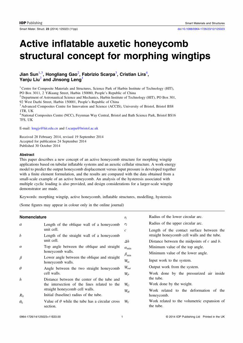
Figure 5 shows a schematic diagram of a single-cell activehoneycomb. The bottom cell wall is fixed, while the upperstraight and oblique cell ribs are in constant contact with arigid wall connected to a hinge at an angle of θ. The initialangle of the configuration is θ1. The length of the upper rigidwall is L. The distance between the center of the straight cellwall honeycomb and the hinge (point O) is h. The transversewidth of the structure is w. The unit cell is subjected to
Figure 4. Relationships between c R/ 0, r R/1 0, and r R/2 0 versus θ for=h 65 mm.
4
Smart Mater. Struct. 23 (2014) 125023 J Sun et al
loading by weight through a concentrated force located at thetip of the inclined rigid wall.
The model considers the adopted assumptions to simulatethe actuation of the ‘smart-stick’ concept, which is inspired bythe deformation mechanism of spider legs [36–38]. Thewhole system deforms under a rigid-type body motion pro-duced by the inflation of the air inside the tubes (figure 5(a)).As a first approximation, the contribution provided by therestoring force of the tubes subjected to compression by anexternal load is neglected [36–38]. Therefore, the systemreceives as input work (Win) the one generated by the inflationof the two tubes with air (WP):
=W W2 . (13)in P
The input work has to overcome the work done by theweight (WG), the one related to the deformation of the hon-eycomb (WH), the volume expansion of the tube (WV ), and thework related to the tube’s elastic expansion (WE). Therefore,the sum (Wout) of these energies is:
= + + +W W W W W2 2 . (14)out G H V E
Neglecting the influence of nonconservative forces (i.e.,friction) in the system, by conservation of energy one canobtain:
=W W . (15)in out
The work of the pressured air is equal to the internalpressure in one tube ( θP ( )) multiplied by the contact area
between the tube and the wall, and the distance, θhd 2:
∫ θ θ θ=θ
θW
P c whd
( ) ( )
2, (16)P
1
where θc ( ) can be obtained from equation (4).The work done by the weight consists of two parts: the
contribution from the loading weight (G), and the work doneby the weight of the upper rigid wall (Gwall),
∫ ∫
θ θ
= +
= − −
θ
θ
θ
θ
⎛⎝⎜
⎞⎠⎟ ( )
GdS G dS
GG
L
W
2sin sin . (17)
GL
L
L
L
wall
wall
sin
sin
sin 2
sin 2
1
1 1
Note that the contribution from the honeycomb cell wallis neglected because of the intrinsic low weight on the core.The contribution from the strain energy associated with theflexing of the honeycomb ribs (WH) is also neglected becauseof the very weak in-plane stiffness induced by the low relativedensity of the core used for this design.
The angle of the system is θ0 when the tube assumes acircular shape. For θ θ⩽ 0, the work of the tube is equal to thework related to its volume expansion (WV ). The volume of thetube can be obtained from inspection as:
θ π θ θ θ θ θ
π θ θ
= − + +
+ +
⎜ ⎟
⎜ ⎟
⎡⎣⎢
⎛⎝
⎞⎠
⎛⎝
⎞⎠
⎤⎦⎥
( )V r c r r
r w
( )2
( ) ( ) ( ) ( )
2( ) . (18)
12
2 1
22
Therefore, the work related to the volume change is:
∫
∫
θ Δ θ θ
θ θ θ θ θ
=
= + −
θ
θ
θ
θ
W P V d
P V d V d
( ) ( )
( )( ( ) ( )) . (19)
V1
1
If the pressure is kept constant, the work associated withthe volume expansion depends only on the differencebetween the values of the initial and final volumes.Equation (19) can be therefore simplified into:
θ θ= −( )( )W P V V( ) . (20)V 1
For θ θ> 0, the work on the tube is the work related tothe elastic expansion of the tube itself. In that case, the tubewill be dilated into a larger circle, and the correspondingmechanical work can be expressed as:
∫ π π=−
= −( )
( )WEA R R
RdR
EA
RR R2 . (21)E
R
R 0
0 00
2
0
From inspection, = θ( )R h tan4, and equation (21) can be
therefore be expressed as:
π θ= −⎜ ⎟⎛⎝⎜
⎛⎝
⎞⎠
⎞⎠⎟W
E
Rh R
Atan
4. (22)E
00
2
Figure 5. (a) Layout of the forces and pressures acting on the singleunit cell. (b) Work of the forces and pressures present in the system.Quantities denoted in blue indicate the input energies, and quantitiesin black are related to the output energies.
5
Smart Mater. Struct. 23 (2014) 125023 J Sun et al
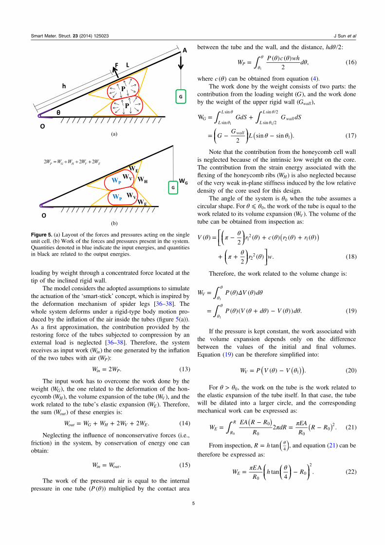
3.3. FE model
Figure 6(a) shows the solid model of the prototype structure,which was used to develop the FE mesh and simulation usingABAQUS 6.10. The lower (wooden) beam is fixed. Theintersection line of the two beams is fixed in displacement andfree in rotation, allowing the upper wooden beam to rotatefreely around this line. Forces along the vertical direction areapplied on the nodes of the right end of the upper beam torepresent the loading weights. The honeycomb unit cell isfixed between the two beams. The compressed shape of thetube is calculated by using equations (4)–(6). The two tubesare in contact with the honeycomb walls and with each other,but no contact friction is considered in this analysis. A uni-form pressure distribution is applied to the internal surface ofthe tube (figure 6(b)). The deformations of the honeycomb areobtained under different loading weights and input pressures.In this work, the tube is described by as having both LE andhyperelastic (Mooney-Rivlin) properties. Both the linearelastic isotropic material (Young’s modulus 3MPa [44],Poisson’s ratio of 0.4) and the hyperelastic isotropic material(C10 = 2.3MPa, C01 = 0.58MPa [45], and D1 = 0.001) arereferred to the polyvinyl chloride (PVC) material of the tubes.Each tube was meshed using 9952 C3D20R elements (10elements across the thickness of the tubes). The woodenplates (Young’s modulus of 12 GPa, Poisson’s ratio of 0.2)and the paper honeycomb (Young’s modulus of 246 GPa,Poison’s ratio of 0.10) were meshed using 2000 and 4976C3D20R elements, respectively. The solver used consisted ofa medial axis algorithm.
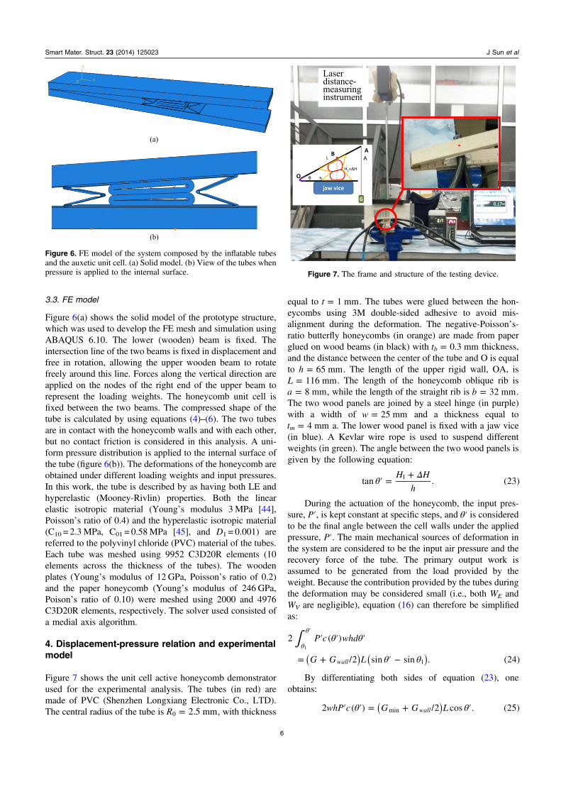
4. Displacement-pressure relation and experimentalmodel
Figure 7 shows the unit cell active honeycomb demonstratorused for the experimental analysis. The tubes (in red) aremade of PVC (Shenzhen Longxiang Electronic Co., LTD).The central radius of the tube is =R 2.5 mm0 , with thickness
equal to =t 1 mm. The tubes were glued between the hon-eycombs using 3M double-sided adhesive to avoid mis-alignment during the deformation. The negative-Poisson’s-ratio butterfly honeycombs (in orange) are made from paperglued on wood beams (in black) with =t 0.3 mmb thickness,and the distance between the center of the tube and O is equalto =h 65 mm. The length of the upper rigid wall, OA, is
=L 116 mm. The length of the honeycomb oblique rib is=a 8 mm, while the length of the straight rib is =b 32 mm.
The two wood panels are joined by a steel hinge (in purple)with a width of =w 25 mm and a thickness equal to
=t 4 mmm a. The lower wood panel is fixed with a jaw vice(in blue). A Kevlar wire rope is used to suspend differentweights (in green). The angle between the two wood panels isgiven by the following equation:
θΔ
′ =+H H
htan . (23)1
During the actuation of the honeycomb, the input pres-sure, ′P , is kept constant at specific steps, and θ′ is consideredto be the final angle between the cell walls under the appliedpressure, ′P . The main mechanical sources of deformation inthe system are considered to be the input air pressure and therecovery force of the tube. The primary output work isassumed to be generated from the load provided by theweight. Because the contribution provided by the tubes duringthe deformation may be considered small (i.e., both WE andWV are negligible), equation (16) can therefore be simplifiedas:
∫ θ θ
θ θ
′ ′ ′
= + ′ −θ
θ′
( ) ( )
P c whd
G G L
2 ( )
/2 sin sin . (24)wall 1
1
By differentiating both sides of equation (23), oneobtains:
θ θ′ ′ = + ′( )whP c G G L2 ( ) /2 cos . (25)wallmin
Figure 6. FE model of the system composed by the inflatable tubesand the auxetic unit cell. (a) Solid model. (b) View of the tubes whenpressure is applied to the internal surface.
A
Figure 7. The frame and structure of the testing device.
6
Smart Mater. Struct. 23 (2014) 125023 J Sun et al

θθ
′ =+ ′
′( )
PG G L
whc
/2 cos
2 ( ). (26)
wall
Equations (21) and (24) can be used to predict the inputpressure for a needed vertical height, ΔH , on the honeycombstructure.
In the experimental case, the initial geometry parametersare =H 4 mm1 and θ = °3.521 . The distance, ΔH , is mea-sured using a laser distance-measuring instrument (KEY-ENCE LK-GD500, accuracy: 0.01 mm) from a distance of450 mm.
For this experiment, only one tube is used. The tube wasobserved to undergo some localized kinking, but no internalair blockage was apparent. One end of the tube was closed,and the opposite was connected to an air compressor pump. Apneumatic relief valve controlled the input pressure. Thepressure was measured using an air pressure gauge (YB-150A, Hongqi Instrument Co. Ltd, range: 0–0.6MPa, accu-racy: 0.005MPa). The distance, ΔH , is measured at increas-ing values of input pressure under different weights (600 g,800 g, and 1000 g). The step for a single increase test is20 kPa, and the step for the three cyclic tests is 40 kPa.
5. Results and discussions
Figure 8 shows the ΔH-P′ relations predicted by FE using theLE and hyperelastic mechanical properties for the tubes,respectively. As expected, the higher the weight, the lower themaximum change in height ΔH. When the input pressure islarger than 0.1MPa, it is apparent that the deformationincreases linearly with the input pressure, and the deformationin the LE model is larger than the deformation obtained fromthe hyperelastic system. The LE model consistently providesa softer response than the hyperelastic model. The softeningbecomes significantly important when the input pressure ishigher, and it reaches a 22% decrease in ΔH for pressurevalues of 0.28MPa. This fact can be explained by observingthat at the beginning of the pressure loading, the LE tubes firsttend to expand horizontally (along the h-direction) without
normal deformation, a feature that the hyperelastic tubes donot show. Therefore, the tubes defined by the linear elasticmaterial tend to have a bigger deformation along the outputdisplacement.
Figure 9 shows the general comparison of the ΔH-P′relations from the experimental, hyperelastic FE, and analy-tical models for three different weight configurations. It isapparent that the model tends to always be conservativeagainst both the experimental output deformation and the FEdeformation, especially when the input pressure is lower than0.20MPa. However, the analytical model tends to approachboth the experimental and FE predictions at higher pressures.One can also see a very good agreement when the lowestweight loading condition (600 g) is applied. The FE modelalso tends to provide a softer response under 0.18MPa,although it is stiffer than the one predicted by the analyticalmodel. From observing figures 8 and 9, it is apparent thatcontact friction and stick-slip (neglected both in the analyticaland FE models) play a significant role at lower levels of inputpressure and external weight. Moreover, a precise modelingof both the geometry and the nonlinear geometric deformationof the tubes also appears to be an important aspect that theanalytical model does not take into account at low P’ and highG values. The analytical model is also limited by the rigid-body load transfer assumption typical of the smart-stickactuation unit. Another limit of the analytical model presentedin equation (24) and represented in figure 9 is the lack of theresorting force from the compressed tubes. However, it isworth noting that in the present model and sample, only oneinflatable unit was present, while the ‘smart-stick’ concept(and the related analytical model) tend to work efficientlywhen large numbers of smaller repeating units are connectedtogether [36], similar to the configuration proposed infigure 1. High levels of input pressure show that stick-slip andcontact friction are significantly less important, and theapproximation used to describe the tubes in the analyticalmodel (circular with linear isotropic material) is sufficient toprovide an adequate comparison with the experimentalresults.
Figure 8. ΔH-P′ relations from the FE simulations using both the LEand hyperelastic tube models. Figure 9. Curves of ′p versus ΔH for the experimental, FE
hyperelastic material, and analytical models.
7
Smart Mater. Struct. 23 (2014) 125023 J Sun et al
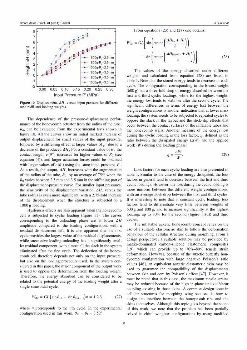
The dependence of the pressure-displacement perfor-mance of the honeycomb actuator from the radius of the tube,R0, can be evaluated from the experimental tests shown infigure 10. All the curves show an initial marked increase ofoutput displacement for small values of the input pressure,followed by a stiffening effect at larger values of p’ due to adecrease of the produced ΔH . For a constant value of θ′, thecontact length, θ′c ( ), increases for higher values of R0 (seeequation (4)), and larger actuation forces could be obtainedwith larger values of θ′c ( ) using the same input pressure, ′P .As a result, the output, ΔH , increases with the augmentationof the radius of the tube, R0, by an average of 75% when theR0 varies between 2.5 mm and 3.5 mm in the stiffening part ofthe displacement-pressure curve. For smaller input pressures,the sensitivity of the displacement variation, ΔH , versus thetube radius is even more significant, with a 2.75-fold increaseof the displacement when the structure is subjected to a1000 g loading.
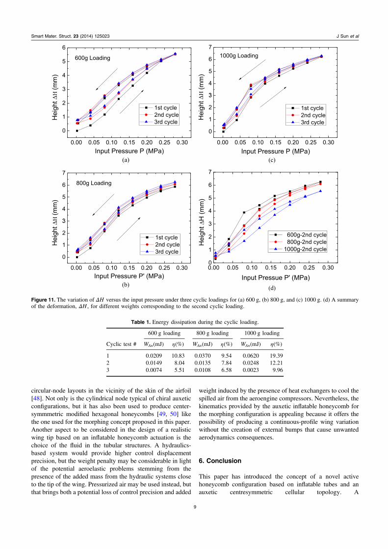
Hysteresis effects are also apparent when the honeycombcell is subjected to cyclic loading (figure 11). The curvescorresponding to the unloading phase are at lower ΔHamplitude compared to the loading configuration, with aresidual displacement left. It is also apparent that the firstcycle provides the largest value of the residual displacements,while successive loading-unloading has a significantly smal-ler residual component, with almost all the slack in the systemeliminated after the first cycle. The deflection of the honey-comb cell therefore depends not only on the input pressure,but also on the loading procedure used. In the system con-sidered in this paper, the major component of the output workis used to oppose the deformation from the loading weight.Therefore, the energy absorbed can be considered to berelated to the potential energy of the loading weight after asingle sinusoidal cycle:
θ θ= − =−( )W GL nsin sin 1.2.3... (27)An n n1 1( 1)
where n corresponds to the nth cycle. In the experimentalconfiguration used in this work, θ θ= = °3.5210 1 .
From equations (23) and (27) one obtains:
Δ
Δ
=+
−+−
⎡⎣⎢
⎛⎝⎜
⎛⎝⎜
⎞⎠⎟
⎞⎠⎟
⎛⎝⎜
⎛⎝⎜
⎞⎠⎟
⎞⎠⎟
⎤⎦⎥⎥
W GL acH H
h
acH H
h
sin tan
sin tan . (28)
Ann
n
1 1
1( 1) 1
The values of the energy absorbed under differentweights and calculated from equation (28) are listed intable 1. Note that the stored energy tends to decrease at eachcycle. The configuration corresponding to the lowest weight(600 g) has a three-fold drop of energy absorbed between thefirst and third cyclic loadings, while for the highest weight,the energy lost tends to stabilize after the second cycle. Thesignificant differences in terms of energy lost between theweight configurations is another indication that at lower massloading, the system needs to be subjected to repeated cycles tooppose the slack in the layout and the stick-slip effects thatoccur between the contact surfaces of the inflatable tubes andthe honeycomb walls. Another measure of the energy lostduring the cyclic loading is the loss factor, η, defined as theratio between the dissipated energy (ΔW ) and the appliedwork (W ) during the loading phase:
η Δ= W
W. (29)
Loss factors for each cyclic loading are also presented intable 1. Similar to the case of the energy dissipated, the lossfactors in general tend to decrease between the first and thirdcyclic loadings. However, the loss during the cyclic loading ismore uniform between the different weight configurations,with an average 50% drop between the first and third cycles.It is interesting to note that at constant cyclic loading, lossfactors tend to differentiate very little between weights of600 g and 800 g, and to increase significantly at the highestloading, up to 80% for the second (figure 11(d)) and thirdcycles.
The inflatable auxetic honeycomb concept relies on theuse of a suitable elastomeric skin to follow the deformationbehaviour of the cellular structure during morphing. From adesign perspective, a suitable solution may be provided bymatrix-dominated carbon-silicone elastomeric composites[19], which can provide up to 70%–80% tensile straindeformation. However, because of the auxetic butterfly hon-eycomb configuration with large negative Poisson’s ratiovalues [46], an equivalent auxetic elastomeric skin may beused to guarantee the compatibility of the displacementsbetween skin and core by Poisson’s effect [47]. However, itmust be noted that in this case, the maximum tensile strainsmay be reduced because of the high in-plane uniaxial/shearcoupling existing in those skins. A common design issue incellular structures for morphing wing sections is how todesign the interface between the honeycomb ribs and theskins themselves. Although this topic goes beyond the scopeof this work, we note that the problem has been partiallysolved in chiral wingbox configurations by using modified
Figure 10. Displacement, ΔH , versus input pressure for differenttube radii and loading weights.
8
Smart Mater. Struct. 23 (2014) 125023 J Sun et al
circular-node layouts in the vicinity of the skin of the airfoil[48]. Not only is the cylindrical node typical of chiral auxeticconfigurations, but it has also been used to produce center-symmmetric modified hexagonal honeycombs [49, 50] likethe one used for the morphing concept proposed in this paper.Another aspect to be considered in the design of a realisticwing tip based on an inflatable honeycomb actuation is thechoice of the fluid in the tubular structures. A hydraulics-based system would provide higher control displacementprecision, but the weight penalty may be considerable in lightof the potential aeroelastic problems stemming from thepresence of the added mass from the hydraulic systems closeto the tip of the wing. Pressurized air may be used instead, butthat brings both a potential loss of control precision and added
weight induced by the presence of heat exchangers to cool thespilled air from the aeroengine compressors. Nevertheless, thekinematics provided by the auxetic inflatable honeycomb forthe morphing configuration is appealing because it offers thepossibility of producing a continuous-profile wing variationwithout the creation of external bumps that cause unwantedaerodynamics consequences.
6. Conclusion
This paper has introduced the concept of a novel activehoneycomb configuration based on inflatable tubes and anauxetic centresymmetric cellular topology. A
Figure 11. The variation of ΔH versus the input pressure under three cyclic loadings for (a) 600 g, (b) 800 g, and (c) 1000 g. (d) A summaryof the deformation, ΔH , for different weights corresponding to the second cyclic loading.
Table 1. Energy dissipation during the cyclic loading.
600 g loading 800 g loading 1000 g loading
Cyclic test # WAn(mJ) η(%) WAn(mJ) η(%) WAn(mJ) η(%)
1 0.0209 10.83 0.0370 9.54 0.0620 19.392 0.0149 8.04 0.0135 7.84 0.0248 12.213 0.0074 5.51 0.0108 6.58 0.0023 9.96
9
Smart Mater. Struct. 23 (2014) 125023 J Sun et al
phenomenological model from the work-energy equation hasbeen developed to obtain an input pressure/output displace-ment relation for the actuation system. An experimentalmodel has also been developed, and the results have beencompared with the predictions from the analytical model andFE simulations representing the tube/auxetic cell prototype.An analysis of the hysteresis due to cyclic loading on theactive honeycomb configuration has also been performed.The sample has shown the feasibility of the concept forpossible wingtip morphing configurations, and the promise ofusing the auxetic active honeycomb for further designs.
Acknowledgments
This work was supported by the National Natural ScienceFoundation of China (Grant No.11225211, No.11272106). JSun would also like to thank the Chinese Scholarship Council(CSC) for funding his research at the University of Bristol. F.S. is also grateful to the European Commission for the FP7-AAT-2012-RTD-L0-341509 project, which provides theinfrastructure logistics of the activities described in this paper.The authors would also like to thank the reviewers for theircomments and suggestions on this paper.
References
[1] Barbarino S, Bilgen O, Ajaj R M, Friswell M I and Inman D J2011 A review of morphing aircraft J. Intell. Mater. Syst.Struct. 22 823–77
[2] Gomez J C and Garcia E 2011 Morphing unmanned aerialvehicles Smart Mater. Struct. 20 103001
[3] Smith D D, Ajaj R M, Isikveren A T and Friswell M I 2012Multi-objective optimization for the multiphase design ofactive polymorphing wings J. Aircraft 49 1153–60
[4] Bourdin P, Gatto A and Friswell M I 2008 Aircraft control viavariable cant-angle winglets J. Aircraft 45 414–23
[5] Gatto A, Bourdin P and Friswell M I 2010 Experimentalinvestigation into articulated winglet effects on flying wingsurface pressure aerodynamics J. Aircraft 47 1811–5
[6] Falcão L, Gomes A A and Suleman A 2011 Aero-structuraldesign optimization of a morphing wingtip J. Intell. Mater.Syst. Struct. 22 1113–24
[7] Daniele E, Fenza A and Vecchia P D 2012 Conceptualadaptive wing-tip design for pollution reductions J. Intell.Mater. Syst. Struct. 23 1197–212
[8] Ursache N M, Melin T, Isikveren A T and Friswell M I 2008Technology integration for poly-morphing wingletsdevelopment Proc. SMASIS08, ASME Conf. on SmartMaterials, Adaptive Structures and Intelligent Systems(Ellicott City, MD, 28–30 October 2008) SMASIS2008-496
[9] Gatto A, Mattioni F and Friswell M I 2009 Experimentalinvestigation of bistable winglets to enhance wing lifttakeoff capability J. Aircraft 46 647–55
[10] Mattioni F, Weaver P M, Potter K D and Friswell M I 2008The application of thermally induced multistable compositesto morphing aircraft structures Proc. SPIE Industrial andCommercial Applications of Smart Structures Technologies2008 693012
[11] Manzo J and Garcia E 2009 Demonstration of an in situmorphing hyperelliptical cambered span wing mechanismSmart Mater. Struct. 19 025012
[12] Kuder I K, Arrieta A F, Raither W E and Ermanni P 2013Variable stiffness material and structural concepts formorphing applications Prog. Aerospace Sci. 63 33–55
[13] Lachenal X, Daynes S and Weaver P M 2013 Review ofmorphing concepts and materials for wind turbine bladeapplications Wind Energy 16 283–307
[14] Saito K, Agnese F and Scarpa F 2011 A cellular kirigamimorphing wingbox concept J. Intell. Mater. Syst. Struct. 22935–44
[15] Bornengo D, Scarpa F and Remillat C 2005 Evaluation ofhexagonal chiral structure for morphing airfoil concept Proc.Instn Mech. Eng. G: J. Aerospace Eng. 219 185–92
[16] Heo H, Ju J and Kim D M 2013 Compliant cellular structures:application to a passive morphing airfoil Compos. Struct.106 560–9
[17] Martin J, Heyder-Bruckner J J, Remillat C, Scarpa F,Potter K and Ruzzene M 2008 The hexachiral prismaticwingbox concept Phys. Status Solidi B 245 570–7
[18] http://papersofa.com/[19] Bubert E A, Woods B K S, Lee K, Kothera C S and
Wereley N M 2010 Design and fabrication of a passive 1Dmorphing aircraft skin J. Intell. Mater. Syst. Struct. 211699–717
[20] Vocke R D III, Kothera C S, Woods B and Wereley N M 2011Development and testing of a span-extending morphingwing J. Intell. Mater. Syst. Struct. 22 879–90
[21] Vocke R D III, Kothera C S and Wereley N M 2012Development of a Span-extending blade tip system for areconfigurable helicopter rotor 53rd AIAA/ASME/ASCE/AHS/ASC Structures, Structural Dynamics and MaterialsConf. (Honolulu, Hawaii, 23–26 April 2012) AIAA2012-1664
[22] Liu W D, Zhu H, Zhou S Q, Bai Y L, Wang Y and Zhao C S2013 In-plane corrugated cosine honeycomb for 1Dmorphing skin and its application on variable camber wingChin. J. Aeronautics 26 935–42
[23] Barbarino S, Gandhi F and Webster S D 2011 Design ofextendable chord sections for morphing helicopter rotorblades J. Intell. Mater. Syst. Struct. 22 891–905
[24] Daynes S and Weaver P M 2012 Design and testing of adeformable wind turbine blade control surface Smart Mater.Struct. 21 105019
[25] Jacobs S, Coconnier C, DiMaio D, Scarpa F, Toso M andMartinez J 2012 Deployable auxetic shape memory alloycellular antenna demonstrator: design, manufacturing andmodal testing Smart Mater. Struct. 21 075013
[26] Chen Y, Scarpa F, Remillat C, Farrow I R, Liu Y J andLeng J S 2013 Curved Kirigami SILICOMB cellularstructures with zero Poisson’s ratio for large deformationsand morphing J. Intell. Mat. Syst. Struct. 25 731−43
[27] Virk K, Monti A, Trehard T, Marsh M, Hazra K, Boba K,Remillat C D L, Scarpa F and Farrow I R 2013 SILICOMBPEEK kirigami cellular structures: mechanical response andenergy dissipation through zero and negative stiffness SmartMater. Struct. 22 084014
[28] Hassan M, Scarpa F, Ruzzene M and Mohammed N A 2008Smart shape memory alloy chiral honeycomb Mater. Sci.Eng. A 481 654–7
[29] Okabe Y and Sugiyama H 2009 Shape variable sandwichstructure with SMA honeycomb core and CFRP skins Proc.SPIE 7288 728817
[30] Perkins D A, Reed J L Jr and Havens E 2004 Morphing wingstructures for loitering air vehicles 45th AIAA/ASME/ASCE/AHS/ASC structures, Structural Dynamics and Materials Conf.(Palm Springs, CA, 19–22 April 2004) AIAA 2004-1888
10
Smart Mater. Struct. 23 (2014) 125023 J Sun et al
[31] Vos R and Barrett R 2011 Mechanics of pressure-adaptivehoneycomb and its application to wing morphing SmartMater. Struct. 20 094010
[32] Pagitz M, Lamacchia E and Hol J 2012 Pressure-actuatedcellular structures Bioinsp. Biomim. 7 016007
[33] Pagitz M and Bold J 2013 Shape-changing shell-like structuresBioinsp. Biomim. 8 016010
[34] Chang B, Chew A, Naghshineh N and Menon C 2012 A spatialbending fluidic actuator: fabrication and quasi-staticcharacteristics Smart Mater. Struct. 21 045008
[35] Mazlouman S J, Chang B, Mahanfar A, Mahanfar A,Vaughan R G and Menon C 2013 Beam-steering antennausing bending fluidic actuators IEEE Trans. AntennasPropag. 61 5287–90
[36] Berring J, Kianfar K, Lira C, Menon C and Scarpa F 2010 Asmart hydraulic joint for future implementation in roboticstructures Robotica 28 1045–56
[37] Menon C and Lira C 2006 Active articulation for future spaceapplications inspired by the hydraulic system of spidersBioinsp. Biomim. 1 52–61
[38] Lira C, Menon C, Kianfar K and Scarpa F 2009 Bioinspiredhydraulic joint for highly redundant robotic platformsASME/IFToMM Int. Conf. on Reconfigurable Mechanismsand Robots pp 434–8
[39] Schulz S, Pylatiuk C, Reischl M, Martin J, Mikut R andBretthauer G 2005 A hydraulically driven multifunctionalprosthetic hand Robotica 23 293–9
[40] Alderson A and Alderson K 2007 Auxetic materials Proc.IMechE G: J. Aerospace Eng. 221 565–75
[41] Grima J N and Evans K E 2000 Auxetic behavior from rotatingsquares J. Mater. Sci. Lett. 19 1563–5
[42] Bianchi M, Scarpa F L and Smith C W 2008 Stiffness andenergy dissipation in polyurethane auxetic foams J. Mater.Sci. 43 5851–60
[43] Ruzzene M and Scarpa F 2005 Directional and band-gapbehavior of periodic auxetic lattices Phys. Status Solidi B242 665–80
[44] Wilkes C, Daniels C and Summers J 2005 PVC Handbook vol5 pp 183−4 ISBN3-446-22714-8
[45] Neerincx P E 2007 Design and realization of a disposablebioreactor Master’s Thesis Eindhoven University ofTechnology, Netherlands
[46] Scarpa F, Panayiotou P and Tomlinson G 2000 Numerical andexperimental uniaxial loading on in-plane auxetichoneycombs J. Strain Analysis for Eng. Des. 35 383–8
[47] Chen Y J, Scarpa F, Farrow I R, Liu Y J and Leng J S 2013Composite flexible skin with large negative Poisson’s ratiorange: numerical and experimental analysis Smart Mater.Struct. 22 045005
[48] Martin J, Heyder-Bruckner J J, Remillat C, Scarpa F,Potter K and Ruzzene M 2008 The hexachiral prismaticwingbox concept Phys. Status Solidi B 245 570–7
[49] Miller W, Smith C W, Scarpa F and Evans K E 2010 Flatwisebuckling optimization of hexachiral and tetrachiralhoneycombs Compos. Sci. Technol. 70 1049–56
[50] Chen Q, Pugno N, Zhao K and Li Z Y 2014 Mechanicalproperties of a hollow-cylindrical-joint honeycomb Compos.Struct. 109 68–74
11
Smart Mater. Struct. 23 (2014) 125023 J Sun et al