active harmonic filter 2/2015
TRANSCRIPT

AccuSine SWP20 - 480 A
Installation
Active Harmonic Filter
2/2015
www.schneider-electric.com

Legal InformationThe Schneider Electric brand and any registered trademarks of Schneider ElectricIndustries SAS referred to in this guide are the sole property of Schneider ElectricSA and its subsidiaries. They may not be used for any purpose without the owner'spermission, given in writing. This guide and its content are protected, within themeaning of the French intellectual property code (Code de la propriétéintellectuelle français, referred to hereafter as "the Code"), under the laws ofcopyright covering texts, drawings and models, as well as by trademark law. Youagree not to reproduce, other than for your own personal, noncommercial use asdefined in the Code, all or part of this guide on any medium whatsoever withoutSchneider Electric's permission, given in writing. You also agree not to establishany hypertext links to this guide or its content. Schneider Electric does not grantany right or license for the personal and noncommercial use of the guide or itscontent, except for a non-exclusive license to consult it on an "as is" basis, at yourown risk. All other rights are reserved.
Electrical equipment should be installed, operated, serviced, and maintained onlyby qualified personnel. No responsibility is assumed by Schneider Electric for anyconsequences arising out of the use of this material.
As standards, specifications, and designs change from time to time, please ask forconfirmation of the information given in this publication.

20 - 480 A
Table of Contents
Important Safety Information.....................................................................5Safety Precautions .....................................................................................6Electrical Safety .........................................................................................8
Specifications ..............................................................................................9Input Specifications ....................................................................................9Technical Characteristics ............................................................................9Upstream Protection .................................................................................10
Recommended Protection and Connection to Active Harmonic Filter20 A Terminal Block.............................................................................10Recommended Protection and Connection to Active Harmonic Filter30 A Terminal Block.............................................................................12Recommended Protection and Connection to Active Harmonic Filter45 A Terminal Block.............................................................................14Recommended Protection and Connection to Active Harmonic Filter60 A Terminal Block.............................................................................16Recommended Protection and Connection to Active Harmonic Filter90 A Terminal Block.............................................................................18Recommended Protection and Connection to Active Harmonic Filter120 ATerminal Block...........................................................................20
Recommended Cable Sizes ......................................................................22Recommended Power Cable Sizes ......................................................22Recommended Signal Cable Sizes ......................................................22
Closed Current Sensors ............................................................................22Round Opening Current Sensors ...............................................................24Rectangular Opening Current Sensors.......................................................24Environmental ..........................................................................................25Heat Dissipation .......................................................................................25Weights and Dimensions...........................................................................26One-Line Diagrams ..................................................................................26
20 A, 30 A, 45 A or 60 A ......................................................................2690 A or 120 A......................................................................................27Two 20 A, 30 A, 45 A or 60 A in Parallel ................................................27Two 90 A or 120 A in Parallel ...............................................................28
Mechanical Assembly ..............................................................................29Clearance ................................................................................................29
Active Harmonic Filter Stand Alone ......................................................30Two Active Harmonic Filters in Cabinet.................................................31Two Active Harmonic Filters Side by Side .............................................32
Prepare for Installation .............................................................................33Connect Ribbon Cables ...........................................................................34
Connect Ribbon Cables for 90 A and 120 A Active Harmonic Filters .............34Connect Ribbon Cables for Parallel Installations .........................................35
Mount the Current Sensors on the Cables or the Busbars .................36Connect the Current Sensors..................................................................37Connect Dry Contacts ..............................................................................38Input and Output Contacts.......................................................................39
990-4530B-001 3

20 - 480 A
Modbus & JBUS Communication System.............................................40RS485 Interface .......................................................................................40
RS485 Topology of 2–Wire Inter-Enclosure Link....................................41RS485 Topology of 4–Wire Inter-Enclosure Link....................................42
Configure RS485 Link...............................................................................43RS485 Link Interface...........................................................................43Polarization ........................................................................................43Matching ............................................................................................43Choose the Connecting Cable .............................................................44Polarization and/or Termination via the External Connector ....................44Polarization and/or Matching via the MERY Board.................................45
4 990-4530B-001

Important Safety Information 20 - 480 A
Important Safety InformationRead these instructions carefully and look at the equipment to become familiar withit before trying to install, operate, service or maintain it. The following safetymessages may appear throughout this manual or on the equipment to warn ofpotential hazards or to call attention to information that clarifies or simplifies aprocedure.
The addition of this symbol to a “Danger” or “Warning” safetymessage indicates that an electrical hazard exists which will result inpersonal injury if the instructions are not followed.
This is the safety alert symbol. It is used to alert you to potentialpersonal injury hazards. Obey all safety messages with this symbolto avoid possible injury or death.
DANGERDANGER indicates a hazardous situation which, if not avoided, will result indeath or serious injury.
Failure to follow these instructions will result in death or serious injury.
WARNINGWARNING indicates a hazardous situation which, if not avoided, could result indeath or serious injury.
Failure to follow these instructions can result in death, serious injury, orequipment damage.
CAUTIONCAUTION indicates a hazardous situation which, if not avoided, could result inminor or moderate injury.
Failure to follow these instructions can result in injury or equipmentdamage.
NOTICENOTICE is used to address practices not related to physical injury. The safetyalert symbol shall not be used with this type of safety message.
Failure to follow these instructions can result in equipment damage.
Please NoteElectrical equipment should only be installed, operated, serviced, and maintainedby qualified personnel. No responsibility is assumed by Schneider Electric for anyconsequences arising out of the use of this material.
990-4530B-001 5

20 - 480 A Important Safety Information
A qualified person is one who has skills and knowledge related to the construction,installation, and operation of electrical equipment and has received safety trainingto recognize and avoid the hazards involved.
Safety Precautions
DANGERHAZARD OF ELECTRIC SHOCK, EXPLOSION, OR ARC FLASH
All safety instructions in this document must be read, understood and followed.
Failure to follow these instructions will result in death or serious injury.
DANGERHAZARD OF ELECTRIC SHOCK, EXPLOSION, OR ARC FLASH
Read all instructions in the Installation Manual before installing or working onAccuSine SWP active harmonic filter.
Failure to follow these instructions will result in death or serious injury.
DANGERHAZARD OF ELECTRIC SHOCK, EXPLOSION OR ARC FLASH
Do not install the active harmonic filter until all construction work has beencompleted and the installation room has been cleaned.
Failure to follow these instructions will result in death or serious injury.
DANGERHAZARD OF ELECTRIC SHOCK, EXPLOSION, OR ARC FLASH
• The product must be installed according to the specifications andrequirements as defined by Schneider Electric. It concerns in particular theexternal and internal protections (upstream breakers, battery breakers,cabling, etc.) and environmental requirements. No responsibility is assumedby Schneider Electric if these requirements are not respected.
• After the active harmonic filter has been electrically wired, do not start up thesystem. Startup must only be performed by Schneider Electric.
Failure to follow these instructions will result in death or serious injury.
DANGERHAZARD OF ELECTRIC SHOCK, EXPLOSION, OR ARC FLASH
The active harmonic filter must be installed according to local and nationalregulations. Install the active harmonic filter according to:
• IEC 60364 (including 60364–4–41- protection against electric shock, 60364–4–42 - protection against thermal effect, and 60364–4–482 - protectionagainst fire),
Failure to follow these instructions will result in death or serious injury.
6 990-4530B-001

Important Safety Information 20 - 480 A
DANGERHAZARD OF ELECTRIC SHOCK, EXPLOSION OR ARC FLASH
• Install the active harmonic filter in a temperature controlled environment freeof conductive contaminants and humidity.
• Install the active harmonic filter on a non-inflammable, level and solid surface(e.g. concrete) that can support the weight of the system.
Failure to follow these instructions will result in death or serious injury.
DANGERHAZARD OF ELECTRIC SHOCK, EXPLOSION OR ARC FLASH
The active harmonic filter is not designed for and must therefore not be installedin the following unusual operating environments:
• Damaging fumes
• Explosive mixtures of dust or gases, corrosive gases, or conductive or radiantheat from other sources
• Moisture, abrasive dust, steam or in an excessively damp environment
• Fungus, insects, vermin
• Salt-laden air or contaminated cooling refrigerant
• Pollution degree higher than 2 according to IEC 60664-1
• Exposure to abnormal vibrations, shocks, and tilting
• Exposure to direct sunlight, heat sources, or strong electromagnetic fields
Failure to follow these instructions will result in death or serious injury.
DANGERHAZARD OF ELECTRIC SHOCK, EXPLOSION, OR ARC FLASH
Do not drill/punch holes for cables or conduits with the gland plates installed anddo not drill/punch in close proximity to the active harmonic filter.
Failure to follow these instructions will result in death or serious injury.
WARNINGHAZARD OFARC FLASH
Do not make mechanical changes to the product (including removal of cabinetparts or drilling/cutting of holes) that are not described in the Installation Manual.
Failure to follow these instructions can result in death, serious injury, orequipment damage.
WARNINGHAZARD OF OVERHEATING
Respect the space requirements around the active harmonic filter and do notcover the product’s ventilation openings when the active harmonic filter is inoperation.
Failure to follow these instructions can result in death, serious injury, orequipment damage.
990-4530B-001 7

20 - 480 A Important Safety Information
Electrical Safety
DANGERHAZARD OF ELECTRIC SHOCK, EXPLOSION OR ARC FLASH
• Electrical equipment must be installed, operated, serviced, and maintainedonly by qualified personnel.
• The active harmonic filter must be installed in a room with restricted access(qualified personnel only).
• Apply appropriate personal protective equipment (PPE) and follow safeelectrical work practices.
• Turn off all power supplying the active harmonic filter before working on orinside the equipment.
• Before working on the active harmonic filter, check for hazardous voltagebetween all terminals including the protective earth.
• The active harmonic filter contains an internal energy source. Hazardousvoltage can be present even when disconnected from the utility/mains supply.Before installing or servicing the active harmonic filter, ensure that the unitsare OFF and that utility/mains and batteries are disconnected. Wait fiveminutes before opening the active harmonic filter to allow the capacitors todischarge.
• A disconnection device (e.g. disconnection circuit breaker or switch) must beinstalled to enable isolation of the active harmonic filter from upstream powersources in accordance with local regulations. This disconnection device mustbe easily accessible and visible.
• The active harmonic filter must be properly earthed/grounded and due to ahigh leakage current, the earthing/grounding conductor must be connectedfirst.
Failure to follow these instructions will result in death or serious injury.
8 990-4530B-001

Specifications 20 - 480 A
Specifications
Input Specifications
Nominal voltage (V) 400 - 20% + 15%
Connection type 3-wire (3P)4-wire (3P+N)1
Input frequency (Hz) 50 (60 +/- 4)
Technical CharacteristicsNOTE: Typical values in a 400 V 50 Hz three-phase system.
20 A 30 A 45 A 60 A 90 A 120 A
Compensation type RMS (conditioning capacity decreases with the frequency of the orders to be conditioned)
Nominal current in the neutral 3 x In in each phase (result of harmonic recombination into the neutral)
Compensated harmonic orders H2 to H50 (parameter setting possible)Global or selective compensation
Dynamic capacity in di/dt > 100 kA/s > 200 kA/s > 400 kA/s
Response time 40 ms
THDI Load THDI/input THDI ≥ 10 at the active harmonic filter nominal current if:
• load THDI > 40%
• input THDI > 4% at the active harmonic filter nominal current if load THDI < 40%
• global compensation reduction rate THDI = I-harmonic/I-fundamental
Overload Limiting to nominal currentContinuous limiting operation possible
Inrush current Less than I Nominal without matching autotransformer
990-4530B-001 9
1. Operation is possible on single-phase or unbalanced load)

20 - 480 A Specifications
Upstream ProtectionNOTE: Protection must be determined in compliance with the standards in forceand in accordance with selectivity requirements. These models are for guidanceonly and do not involve the responsibility of Schneider Electric.
NOTE: One label as shown here is provided and must be applied on the upstreamdisconnection device (e.g. circuit breaker).
Recommended Protection and Connection to Active Harmonic Filter 20 ATerminal Block
NOTE: Is = sizing current
Non-distributed neutral
TT Earthing System
Circuit breaker specifications:
• Circuit breaker range: 32 A 3 poles
• Trip unit: electronic circuit protection type:
• Magnetic between 2.4 to 3.6 In
• Neutral not protected
• Earth leakage protection: 500 mA
Schneider Electric recommendations:
• Circuit breaker: C60 32 A 3P
• Trip unit: Z curve
• Earth leakage protection: C60 Vigi module ; setting to 500 mA
Is = 25 A
N
3
2
1
Distributed neutral
TT Earthing System
Circuit breaker specifications:
• Circuit breaker range: 100 A 4poles / 3 poles protected
• Trip unit:
– Thermal threshold : Ir = 40 A
– Magnetic threshold : Im= 2 x Ir
• Neutral not protected
• Earth leakage protection: depending on the installation
Schneider Electric recommendations:
• Circuit breaker: NSX100 4p3d
• Trip unit: Micrologic2 100 A / Ir setup=40A
• Earth leakage protection: Vigicompact MH or MB, settingdepending on the installation
Is = 25 A
Is = 65 A N
3
2
1
10 990-4530B-001

Specifications 20 - 480 A
TNC Earthing System
Circuit breaker specifications:
• Circuit breaker range: 32 A 3 poles
• Trip unit: electronic circuit protection type:
• Magnetic between 2.4 to 3.6 In
• Neutral not protected
Schneider Electric recommendations:
• Circuit breaker: C60 32 A 3P
• Trip unit: Z curve
Is = 25 A
Is = 65 A N
3
2
1
PEN
TNS Earthing System
Circuit breaker specifications:
• Circuit breaker range: 100 A 4poles / 3 poles protected
• Trip unit:
– Thermal threshold : Ir = 40 A
– Magnetic threshold : Im= 2 x Ir
• Neutral not protected
Schneider Electric recommendations:
• Circuit breaker: NSX100 4p3d
• Trip Unit: Micrologic2 100 A / Ir setup=40 A
Is = 25 A
Is = 65 A N
3
2
1
PE
990-4530B-001 11

20 - 480 A Specifications
Recommended Protection and Connection to Active Harmonic Filter 30 ATerminal Block
NOTE: Is = sizing current
Non-distributed neutral
TT Earthing System
Circuit breaker specifications:
• Circuit breaker range: 32 A 3 poles
• Trip unit: electronic circuit protection type:
• Magnetic between 2.4 to 3.6 In
• Neutral not protected
• Earth leakage protection: 500 mA
Schneider Electric recommendations:
• Circuit breaker: C60 32 A 3P
• Trip unit: Z curve
• Earth leakage protection: C60 Vigi module ;setting to 500 mA
Is = 35 A
N
3
2
1
Distributed neutral
TT Earthing System
Circuit breaker specifications:
• Circuit breaker range: 100 A 4poles / 3 polesprotected
• Trip unit:
– Thermal threshold : Ir = 40 A
– Magnetic threshold : Im= 2 x Ir
• Neutral not protected
• Earth leakage protection: depending on theinstallation
Schneider Electric recommendations:
• Circuit breaker: NSX100 4p3d
• Trip unit : Micrologic2 100 A / Ir setup=40 A
• Earth leakage protection: Vigicompact MH orMB, setting depending on the installation
Is = 35 A
Is = 100 A N
3
2
1
TNC Earthing System
Circuit breaker specifications:
• Circuit breaker range: 32 A 3 poles
• Trip unit: electronic circuit protection type:
• Magnetic between 2.4 to 3.6 In
• Neutral not protected
Schneider Electric recommendations:
• Circuit breaker: C60 32 A 3P
• Trip unit : Z curve
Is = 35 A
Is = 100 A N
3
2
1
PEN
12 990-4530B-001

Specifications 20 - 480 A
TNS Earthing System
Circuit breaker specifications:
• Circuit breaker range: 100 A 4poles / 3 polesprotected
• Trip unit:
– Thermal threshold : Ir = 40 A
– Magnetic threshold : Im= 2 x Ir
• Neutral not protected
Schneider Electric recommendations:
• Circuit breaker: NSX100 4p3d
• Trip unit : Micrologic2 100 A / Ir setup=40A
Is = 35 A
Is = 100 A N
3
2
1
PE
990-4530B-001 13

20 - 480 A Specifications
Recommended Protection and Connection to Active Harmonic Filter 45 ATerminal Block
NOTE: Is = sizing current
Non-distributed neutral
TT Earthing System
Circuit breaker specifications:
• Circuit breaker range: In = 63 A 3 poles
• Trip unit: electronic circuit protection type:Magnetic between 3.2 to 4.8 In
• Earth leakage protection: 1000 mA
Schneider Electric recommendations:
• Circuit breaker: C60 63 A 3P
• Trip unit : B curve
• Earth leakage protection: C60 Vigi module ;setting to 1000 mA
Is = 50 A
N
3
2
1
Distributed neutral
TT Earthing System
Circuit breaker specifications:
• Circuit breaker range: 160 A 4poles / 3 polesprotected
• Trip unit:
– Thermal threshold : Ir = 63 A
– Magnetic threshold : Im= 2 x Ir
• Neutral not protected
• Earth leakage protection: depending on theinstallation
Schneider Electric recommendations:
• Circuit breaker: NSX160 4p3d
• Trip unit : Micrologic2 160 A / Ir setup= 63A
• Earth leakage protection: Vigicompact MH orMB, setting: depending on the installation
Is = 50 A
Is = 150 A N
3
2
1
TNC Earthing System
Circuit breaker specifications:
• Circuit breaker range: In = 63 A 3 poles
• Trip unit: electronic circuit protection type:magnetic between 3.2 to 4.8 In
Schneider Electric recommendations:
• Circuit breaker: C60 63 A 3P
• Trip unit : B curve
Is = 50 A
Is = 150 A N
3
2
1
PEN
14 990-4530B-001

Specifications 20 - 480 A
TNS Earthing System
Circuit breaker specifications:
• Circuit breaker range: 160 A 4poles / 3 polesprotected
• Trip unit:
– Thermal threshold : Ir = 63 A
– Magnetic threshold : Im= 2 x Ir
• Neutral not protected
Schneider Electric recommendations:
• Circuit breaker: NSX160 4p3d
• Trip unit : Micrologic2 100 A / Ir setup=63 A
Is = 50 A
Is = 150 A N
3
2
1
PE
990-4530B-001 15

20 - 480 A Specifications
Recommended Protection and Connection to Active Harmonic Filter 60 ATerminal Block
NOTE: Is = sizing current
Non-distributed neutral
TT Earthing System
Circuit breaker specifications:
• Circuit breaker range: 80 A 3 poles
• Trip unit: electronic circuit protection type:magnetic between 3.2 to 4.8 In
• Earth leakage protection: 1000 mA
Schneider Electric recommendations:
• Circuit breaker: C120H 80A 3P
• Trip unit : B curve
• Earth leakage protection: C60 Vigicomodule; setting to 1000 mA
Is = 65 A
N
3
2
1
Distributed neutral
TT Earthing System
Circuit breaker specifications:
• Circuit breaker range: 250 A 4poles / 3 polesprotected
• Trip unit:
– Thermal threshold : Ir = 100A
– Magnetic threshold : Im= 2 x Ir
• Neutral not protected
• Earth leakage protection: setting dependingof installation
Schneider Electric recommendations:
• Circuit breaker: NSX250 4p3d
• Trip unit : Micrologic2 250 A / Ir setup= 100 A
• Earth leakage protection: Vigicompact MH orMB, setting depending of installation
Is = 65 A
Is = 200 A N
3
2
1
TNC Earthing System
Circuit breaker specifications:
• Circuit breaker range: In=120 A 3 pole
• Trip unit: electronic circuit protection type:magnetic between 3.2 to 4.8 In
Schneider Electric recommendations:
• Circuit breaker: C120H 80 A 3P
• Trip unit : B curve
Is = 65 A
Is = 200 A N
3
2
1
PEN
16 990-4530B-001

Specifications 20 - 480 A
TNS Earthing System
Circuit breaker specifications:
• Circuit breaker range: 250 A 4poles / 3 polesprotected
• Trip unit:
– Thermal threshold : Ir = 100 A
– Magnetic threshold : Im= 2 x Ir
• Neutral not protected
Schneider Electric recommendations:
• Circuit breaker: NSX250 4p3d
• Trip unit : Micrologic2 250 A / Ir setup= 100 A
Is = 65 A
Is = 200 A N
3
2
1
PE
990-4530B-001 17

20 - 480 A Specifications
Recommended Protection and Connection to Active Harmonic Filter 90 ATerminal Block
Non-distributed Neutral
NOTE: Is = sizing current
TT Earthing System
Is = 50 A Is = 50 A
N
3
2
1
N
3
2
1
Is < 50 A
Circuit breaker specifications:
• Circuit breaker range: In = 63 A 3 poles
• Trip unit: electronic circuit protection type: magnetic between 3.2 to 4.8 In
• Earth leakage protection: 1000 mA
Schneider Electric recommendations:
• Circuit breaker: C60 63 A 3P
• Trip unit : B curve
• Earth leakage protection: C60 Vigi module ; setting to 1000 mA
Distributed Neutral
TT Earthing System
N
3
2
1
N
3
2
1
Is < 50 A
Is = 50 A
Is = 150 A
Is = 50 A
Is = 150 A
Circuit breaker specifications:
• Circuit breaker range: 160 A 4poles / 3 poles protected
• Trip unit:
– Thermal threshold : Ir = 63 A
– Magnetic threshold : Im= 2 x Ir
• Neutral not protected
• Earth leakage protection: setting depending of installation
Schneider Electric recommendations:
• Circuit breaker: NSX160 4p3d
• Trip unit : Micrologic2 160A / Ir setup=63 A
• Earth leakage protection: Vigicompact MH or MB, setting depending of installation
18 990-4530B-001

Specifications 20 - 480 A
TNS Earthing System
N
3
2
1
PEN
3
2
1
PE
Is = 50 A
Is = 150 A
Is = 50 A
Is = 150 A
Is < 50 A
Circuit breaker specifications:
• Circuit breaker range: 160 A 4 poles / 3 poles protected
• Trip unit:
– Thermal threshold : Ir = 63 A
– Magnetic threshold : Im= 2 x Ir
• Neutral not protected
Schneider Electric recommendations:
• Circuit breaker: NSX160 4p3d
• Trip unit : Micrologic2 100 A / Ir setup=63A
TNC Earthing System
Is = 50 A Is = 50 A
Is < 50 A
Is = 150 A Is = 150 AN
3
2
1
PENN
3
2
1
PEN
Circuit breaker specifications:
• Circuit breaker range: In = 63 A 3 poles
• Trip unit: electronic circuit protection type: magnetic between 3.2 to 4.8 In
Schneider Electric recommendations:
• Circuit breaker: C60 63 A 3P
• Trip unit : B curve
990-4530B-001 19

20 - 480 A Specifications
Recommended Protection and Connection to Active Harmonic Filter 120 ATerminal Block
Non-distributed Neutral
NOTE: Is = sizing current
TT Earthing System
N
3
2
1
N
3
2
1Is = 65 A Is = 65 A
Is < 50 A
Circuit breaker specifications:
• Circuit breaker range: 80 A 3 poles
• Trip unit: electronic circuit protection type: magnetic between 3.2 to 4.8 In
• Earth leakage protection: 1000 mA
Schneider Electric recommendations:
• Circuit breaker: C120H 80 A 3P
• Trip unit : B curve
• Earth leakage protection: C60 Vigicomodule ; setting to 1000mA
Distributed Neutral
NOTE: Is = sizing current
TT Earthing System
N
3
2
1
N
3
2
1Is = 65 A
Is = 200 A
Is = 65 A
Is = 200 A
Is < 50 A
Circuit breaker specifications:
• Circuit breaker range: 250 A 4poles / 3 poles protected
• Trip unit:
– Thermal threshold : Ir = 100 A
– Magnetic threshold : Im= 2 x Ir
• Neutral not protected
• Earth leakage protection: setting depending of installation
Schneider Electric recommendations:
• Circuit breaker: NSX250 4p3d
• Trip unit: Micrologic2 250 A / Ir setup=100A
• Earth leakage protection: Vigicompact MH or MB, setting depending of installation
20 990-4530B-001

Specifications 20 - 480 A
TNC Earthing System
N
3
2
1
PEN
Is = 65 A
N
3
2
1
Is = 200 A
Is = 65 A
Is = 200 A PEN
Is < 50 A
Circuit breaker specifications:
• Circuit breaker range: 80 A 3 poles
• Trip unit: electronic circuit protection type: magnetic between 3.2 to 4.8 In
• Earth leakage protection: 1000 mA
Schneider Electric recommendations:
• Circuit breaker: C120H 80 A 3P
• Trip unit: B curve
• Earth leakage protection: C60 Vigicomodule ; setting to 1000 mA
TNS Earthing System
N
3
2
1
PE
Is = 65 A
Is = 200 A
Is = 65 A
Is = 200 A N
3
2
1
PE
Is < 50 A
Circuit breaker specifications:
• Circuit breaker range: 250 A 4poles / 3 poles protected
• Trip unit:
– Thermal threshold : Ir = 100 A
– Magnetic threshold : Im= 2 x Ir
• Neutral not protected
Schneider Electric recommendations:
• Circuit breaker: NSX250 4p3d
• Trip unit : Micrologic2 250 A / Ir setup=100 A
990-4530B-001 21

20 - 480 A Specifications
Recommended Cable Sizes
Recommended Power Cable Sizes
Cable sizes must comply with the standards in force.
Rating Recommended cable sizes (mm²) Terminal blockconnection (mm²)
Diameter of lugs(mm)
Maximum length ofpower cables (m)
Phases Neutral
20 A 2.5 16 35 6 20
30 A 4 25 35 6 20
45 A 10 50 70 8 20
60 A 16 70 70 8 20
90 A 10 per activeharmonic filter
50 per activeharmonic filter
70 8 20
120 A 16 per activeharmonic filter
70 per activeharmonic filter
70 8 20
Recommended Signal Cable Sizes
Connector Recommended cable sizes(mm²)
Type of recommendedconductor
Remark
Dry contact terminal block 0.5 minimum2.5 maximum
Multi-core wires (not supplied) Removable screw terminal block(supplied)
9 point Sub-D Shielded cable (not supplied) Male connector with femalecontacts on the active harmonicfilter; the shielding must beconnected at both ends.
Closed Current SensorsNOTE: Current sensors must be purchased separately.
B2
B1
P
L
H1
H2
A
Rating Externaldimensions H1 /H2 / L / P (mm)
Primary Secondary
B1 / B2 (mm) Max. cablediameter (mm)
Diameter of lugson part A (mm)
Cable size (twisted 2–core cables) (mm²)
Max. lengthof wires (notsupplied) (m)
300/1500/1
76 / 106 / 76 / 44 31 / 11 23 3 or 5 dependingon supplier
Minimum 0.75(recommended) tomaximum 2.5
20
1000/1 90 / 106 / 77 / 44 41 / 11 31
1500/1 165 / 194 / 95 / 40 103 / 22 Busbar only< B1 x B2
2000/1 165 / 194 / 95 / 40 103 / 22 Busbar only
3000/1 180 / 209 / 115 /45
103 / 32 Busbar only
22 990-4530B-001
Specifications 20 - 480 A
Rating Externaldimensions H1 /H2 / L / P (mm)
Primary Secondary
B1 / B2 (mm) Max. cablediameter (mm)
Diameter of lugson part A (mm)
Cable size (twisted 2–core cables) (mm²)
Max. lengthof wires (notsupplied) (m)
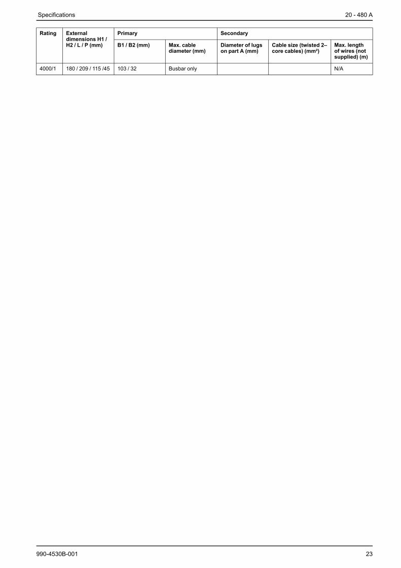
4000/1 180 / 209 / 115 /45 103 / 32 Busbar only N/A
990-4530B-001 23
20 - 480 A Specifications
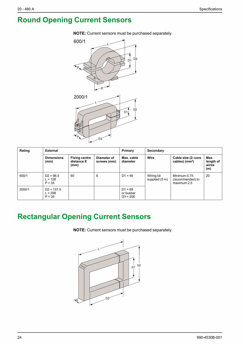
Round Opening Current SensorsNOTE: Current sensors must be purchased separately.
Rating External Primary Secondary
Dimensions(mm)
Fixing centredistance E(mm)
Diameter ofscrews (mm)
Max. cablediameter
Wire Cable size (2–corecables) (mm²)
Max.length ofwires(m)
600/1 D2 = 96.5L = 128P = 35
60 6 D1 = 48 Wiring kitsupplied (5 m)
Minimum 0.75(recommended) tomaximum 2.5
20
2000/1 D2 = 137.5L = 298P = 34
D1 = 69or busbarD3 = 206
Rectangular Opening Current SensorsNOTE: Current sensors must be purchased separately.
24 990-4530B-001

Specifications 20 - 480 A
Rating External Primary Secondary
Dimensions (mm) Max. cablediameter
Diameter of screws(mm)
Cable size (2–corecables) (mm²)
Max. length ofwires (m)
600/1 D2 = 120L = 157P = 34
D1 = 52D3 = 82
5 Minimum 0.75(recommended) tomaximum 2.5
20
2000/1 D2 = 150L = 239P = 34
D1 = 82D3 = 162
Environmental20 A 30 A 45 A 60 A 90 A 120 A
Temperature Storage -25 ºC to 70 ºC
Operating 0 ºC to 40 ºC. ≤ 25 °C is recommended
Elevation Storage ≤ 10000 meters
Operating ≤1000 m without derating>1000 m derating of 10% per additional 1000 m
Operating relative humidity 20% to 95% non–condensing
Protection class IP20
Color RAL 9002 (light grey)
Audible noise according to ISO3746
<58 dBA <59 dBA <62 dBA <64 dBA <65 dBA <67 dBA
VentilationForced air by internal fans (inletvia bottom and outlet via top)
1000 m³/h 2000 m³/h
Heat Dissipation
Rating 20 A 30 A 45 A 60 A 90 A 120 A
Heat dissipation(W)
< 1000 < 1200 < 1900 < 2400 < 3800 < 4800
990-4530B-001 25

20 - 480 A Specifications
Weights and Dimensions
Rating Weight kg Height mm Width mm Depth mm
20 A and 30 A 65 680 540 280
45 A and 60 A 110 780 590 325
90 A and 120 A 2 x 110 2 x 780 2 x 590 325
One-Line Diagrams
DANGERHAZARD OF ELECTRIC SHOCK, EXPLOSION OR ARC FLASH
Isolate all interconnection active harmonic filters before installation and service.
Failure to follow these instructions will result in death or serious injury.
NOTE: The position of the sensors depends on the installation.
NOTE: The active harmonic filter is connected in parallel with the load.
NOTE: The active harmonic filter will be fed from a separate outgoing feeder. Thisline must be protected by a circuit breaker. The active harmonic filter uses this lineto send harmonics destined to compensate the load harmonics back onto themains.
• It is possible to connect two, three or four active harmonic filters with the samerating in parallel to compensate higher loads.
• Each active harmonic filter independently uses current measurements fromthree sensors, regardless of the state of the other active harmonic filter.
• Two cables between the active harmonic filters allow monitoring of allconnected active harmonic filters to determine the share of harmonics to besupplied.
• Each power circuit remains independent and has its own protection.
20 A, 30 A, 45 A or 60 A
26 990-4530B-001

Specifications 20 - 480 A
90 A or 120 A
Two 20 A, 30 A, 45 A or 60 A in Parallel
990-4530B-001 27

20 - 480 A Specifications
Two 90 A or 120 A in Parallel
28 990-4530B-001

Mechanical Assembly 20 - 480 A
Mechanical Assembly90 A and 120 A active harmonic filters are made up of two active harmonic filtershaving the same dimensions as the 45 A and 60 A active harmonic filters. Theseactive harmonic filters can be placed side by side or on top of one another (subjectto installation requirements relating to ventilation).
Rating Fixing centre distance Diameter of fixing screws(mm)
Width (mm) Height (mm)
20 A and 30 A 475 660 8
45 A and 60 A 525 760 8
ClearanceNOTE: Clearance dimensions are published for airflow and service access only.Consult with local safety codes and standards for additional requirements in yourlocal area.
NOTE: The active harmonic filter must be mounted vertically and away from anysource of heat (heating system, transformer, motor, etc.). It may be installed in acabinet or fixed against a wall.
NOTE: Leave a minimum of 600 mm clearance in front of the cabinet for dooropening.
990-4530B-001 29

20 - 480 A Mechanical Assembly
Active Harmonic Filter Stand Alone
30 990-4530B-001

Mechanical Assembly 20 - 480 A
Two Active Harmonic Filters in Cabinet
990-4530B-001 31

20 - 480 A Mechanical Assembly
Two Active Harmonic Filters Side by Side
32 990-4530B-001

Prepare for Installation 20 - 480 A
Prepare for Installation
DANGERHAZARD OF ELECTRIC SHOCK, EXPLOSION, OR ARC FLASH
De-energize the active harmonic filter before carrying out this procedure.
Failure to follow these instructions will result in death or serious injury.
DANGERHAZARD OF ELECTRIC SHOCK, EXPLOSION, OR ARC FLASH
Connect the PE or PEN protective conductor first.
Failure to follow these instructions will result in death or serious injury.
DANGERHAZARD OF ELECTRIC SHOCK, EXPLOSION, OR ARC FLASH
Use adequate insulation sleeves on the power connection lugs to avoid any riskof electrical shock. Refer to IEC 60364-4-41.
Failure to follow these instructions will result in death or serious injury.
NOTE: AccuSine SWP active harmonic filter is suitable for all types of earthingsystems except IT.
1. Check that the active harmonic filter supply circuit breaker placed in your lowvoltage distribution panel is in the open position (O).
2. Remove the front and lower protection plates on the active harmonic filter toaccess the connection terminal block.
3. Fit the lower protection plate of the power terminal block with bushings for cablefeedthrough. If several holes are made to feed the cables through, cut a slotcommon to all the holes to prevent eddy currents from being generated.
4. Connect the PE or PEN conductor on the bolted terminal block.
5. Connect the power cables (L1, L2, and L3) to the terminal block. Ensure correctphase rotation.
NOTE: Fasten the cables near the terminal block to prevent mechanical stresson the conductors.
NOTE: If the cables are pulled, the PE or PEN connection should be the last tobe subjected to the applied force.
990-4530B-001 33

20 - 480 A Connect Ribbon Cables
Connect Ribbon Cables
DANGERHAZARD OF ELECTRIC SHOCK, EXPLOSION, OR ARC FLASH
De-energize the active harmonic filter before carrying out this procedure.
Failure to follow these instructions will result in death or serious injury.
WARNINGHAZARD OFARC FLASH
Fasten the signal cables near the connectors to prevent mechanical stress onthe conductors.
Failure to follow these instructions can result in death, serious injury, orequipment damage.
Connect Ribbon Cables for 90 A and 120 A ActiveHarmonic Filters
NOTE:Wiring is connected via the bottom, in front of the active harmonic filter.
1. Remove the front protection plate.
2. Connect the master active harmonic filter, MERY board to the active harmonicfilter slave DUMY board.
3. Lock the conductor connectors correctly.
4. Fasten the ribbon cable near the connectors to prevent mechanical stress onthe conductors or the conductor shielding earthing.
34 990-4530B-001

Connect Ribbon Cables 20 - 480 A
Connect Ribbon Cables for Parallel Installations1. Connect the MERY board to the PARY board on all active harmonic filter units.
2. Connect the PARY boards between active harmonic filter units (only betweenmaster units for 90 or 120 A) making a loop.
3. Set PARY board straps on all active harmonic filter units according to theillustration.
Active harmonicfilter no. 1
Active harmonicfilter no. 2
Active harmonicfilter no. 3
Active harmonicfilter no. 4
4
123
4
123
4
123
4
123
990-4530B-001 35

20 - 480 AMount the Current Sensors on the Cables
or the Busbars
Mount the Current Sensors on the Cables orthe Busbars
DANGERHAZARD OF ELECTRIC SHOCK, EXPLOSION, OR ARC FLASH
De-energize the active harmonic filter before carrying out this procedure.
Failure to follow these instructions will result in death or serious injury.
CAUTIONRISK OF INCORRECT MOUNTING
Respect and check the phase order and polarity of the current sensors.
Failure to follow these instructions can result in injury or equipmentdamage.
1. Attach the three provided labels to the three current sensors.
2. Mount the three current sensors on each of the cables/busbars L1 and L2, (andL3 if neutral is used) supplying the load.
3. Fasten the screws on both sides to close the sensors.
4. Fix the current sensor to the cables/busbars using the provided fixing lugs.
36 990-4530B-001

Connect the Current Sensors 20 - 480 A
Connect the Current SensorsNOTE: Route the signal cables away from the power cables.
20 A, 30 A, 45 A, and 60 A Active Harmonic Filters 90 A and 120 A Active Harmonic Filters
1. Install the X1 strap in the MAINT position on the CCTY card.
2. Remove the CCTY card that is plugged into the TIFY card via the XR4connector.
3. Turn the CCTY card.
4. Connect the signal cables S1 and S2 from the three current sensors to the XR1,XR2, and XR3 terminals on the CCTY card.
NOTE: The signal cables are provided with the current sensors for cables (S1 isblue and S2 is brown). The signal cables are not provided with the currentsensors for busbars.
5. Refit the CCTY card to the TIFY card with the XR4 connector.
6. Fasten the signal cables near the terminals to prevent mechanical stress on theconductors.
7. Reinstall the front and lower protection plates on the active harmonic filter.
8. Close the door.
9. Close the upstream circuit breaker.
990-4530B-001 37

20 - 480 A Connect Dry Contacts
Connect Dry ContactsNOTE: Contact breaking capacity: P = 2 VA, U = 30 V max., I = 1 A max.
NOTE: Connection to the terminal block can be made while the active harmonicfilter is operating.
NOTE: These contacts comply with safe extra low voltage insulating requirements.
1. Route the cables through the bottom of the enclosure and connect the followingcable:
A. Dry contact cable (not supplied)
B. Removable connector with polarization (supplied)
2. Fasten the signal cables near the connectors to prevent mechanical stress onthe conductors.
3. Configure the dry contact terminal block:2 x voltage-free changeover switches: Active harmonic filter running/stopped.1 x voltage-free changeover switch: Current-limiting operation.
38 990-4530B-001

Input and Output Contacts 20 - 480 A
Input and Output ContactsPin Description
10
9
8
7
6
5
4
3
2
1
NO
NC
NO
NC
NO
NC
10 (not used)
9 Common
8 Active harmonic filter stopped
7 Active harmonic filter running
6 Common
5 Normal operation
4 Limiting operation
3 Common
2 Active harmonic filter stopped
1 Active harmonic filter running
990-4530B-001 39
20 - 480 A Modbus & JBUS Communication System
Modbus & JBUS Communication System
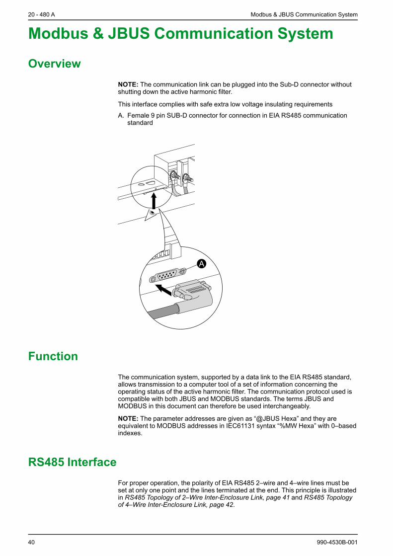
OverviewNOTE: The communication link can be plugged into the Sub-D connector withoutshutting down the active harmonic filter.
This interface complies with safe extra low voltage insulating requirements
A. Female 9 pin SUB-D connector for connection in EIA RS485 communicationstandard
A
FunctionThe communication system, supported by a data link to the EIA RS485 standard,allows transmission to a computer tool of a set of information concerning theoperating status of the active harmonic filter. The communication protocol used iscompatible with both JBUS and MODBUS standards. The terms JBUS andMODBUS in this document can therefore be used interchangeably.
NOTE: The parameter addresses are given as “@JBUS Hexa” and they areequivalent to MODBUS addresses in IEC61131 syntax “%MW Hexa” with 0–basedindexes.
RS485 InterfaceFor proper operation, the polarity of EIA RS485 2–wire and 4–wire lines must beset at only one point and the lines terminated at the end. This principle is illustratedin RS485 Topology of 2–Wire Inter-Enclosure Link, page 41 and RS485 Topologyof 4–Wire Inter-Enclosure Link, page 42.
40 990-4530B-001

Modbus & JBUS Communication System 20 - 480 A
RS485 Topology of 2–Wire Inter-Enclosure Link
A. Master unit
B. Board of an intermediate active harmonic filter
C. Board of an end-of-line active harmonic filter
D. Polarity
E. Connection if end of the line
F. Matching
G. Transmit / receive data
Rp = polarization resistorRa = end-of-line (adaptation) resistor
990-4530B-001 41

20 - 480 A Modbus & JBUS Communication System
RS485 Topology of 4–Wire Inter-Enclosure Link
A. Master unit
B. Board of an intermediate active harmonic filter
C. Board of an end-of-line active harmonic filter
D. Polarity
E. Connection if end of the line
F. Matching
G. Slave receiver
H. Master transmitter
I. Transmit data
J. Receive data
Rp = polarization resistorRa = end-of-line (adaptation) resistor
42 990-4530B-001

Modbus & JBUS Communication System 20 - 480 A
Configure RS485 Link
RS485 Link Interface
NOTE: The micro switches (SA3–X and SA2–X) are in the open position whenactive harmonic filter is delivered.
Active harmonic filter connector seen from below
pin 1: 0 volts
pin 2: RP_5V
pin 3: Ra_A
pin 4: RD-(B’)
pin 5: TD-(B)
pin 6: RP_0V
pin 7: Ra_B
pin 8: RD+(A’)
pin 9: TD+(A)
1 2 3 4 5
6 7 8 9
Polarization
Usage and logic require the master device of the network to polarize the line (Rpresistances).
Matching
Matching (Ra resistances) must be performed at both ends of the line. Toavoid non-matching of the line when disconnecting an end device you shouldprovide one or two matching caps.
Active harmonic filter is a slave device. However, its RS485 link interface can bepolarized and matched in all the chosen connection topologies either via anexternal connector or via micro switches on the active harmonic filter MERY board.
990-4530B-001 43

20 - 480 A Modbus & JBUS Communication System
Choose the Connecting Cable
Choice of a cable depends on the relevant sector of application and on theflowrates and the environment in question. The following transmission cables canbe chosen:
Industrialsector • One, two or three conductor pairs per cable
• Shielding per conductor pair
• Multi-strand conductors
• Telephone shielded twisted pairs may be used
Tertiarysector • One, two or three conductor pairs per cable
• Cable shielding if required
• Shielded or unshielded telephone pairs may be used
Domestic• One or two conductor pairs per cable
• Telephone pairs may be used
Protection
All the shieldings are earthed on either side.
Polarization and/or Termination via the External Connector
The polarity and/or termination must be handled via jumpers in the connectioncable’s male connector.
NOTE: Polarization can be performed on reception or transmission only.
2–Wire RS485 Interface
A. Interface with polarityand with termination.
B. Interface with polarityand without termination.
C. Interface without polarityand with termination.
D. Interface without polarityand without termination.
1
2
3
4
5
6
7
8
9 L+
L-
1
2
3
4
5
6
7
8
9 L+
L-
1
2
3
4
5
6
7
8
9 L+
L-
1
2
3
4
5
6
7
8
9 L+
L-
- A - - B - - C - - D -
4–Wire RS485 Interface
A. Interface with polarityand with termination.
B. Interface with polarityand without termination.
C. Interface without polarityand with termination.
D. Interface without polarityand without termination.
1
2
3
4
5
6
7
8
9
1
2
3
4
5
6
7
8
9
R+
R-
T+
T-
1
2
3
4
5
6
7
8
9
1
2
3
4
5
6
7
8
9
- A - - B - - C - - D -
R+
R-
T+
T-
R+
R-
T+
T-
R+
R-
T+
T-
44 990-4530B-001

Modbus & JBUS Communication System 20 - 480 A
Polarization and/or Matching via the MERY Board
Overview after Dismantling of Protective Cover
A. Configuration switches of the RS485 link
B. Switch closed: in top position
C. Switch open: in bottom position
MERY board
SA2 SA3
R301
1 2 3 41 2 3 4
XM16
ON
ON
ON
OFF
ON
OFFSA2 SA3
A
B
C
PARY board
NUMY board
Configuration of the Micro Switches
NOTE:When configuring the micro switches, it is vital that the active harmonicfilter be de-energized in order to operate without risk in the area reserved for theboards.
NOTE: Polarization is possible both in reception and transmission.
990-4530B-001 45

20 - 480 A Modbus & JBUS Communication System
2-Wire Topology Example
A. Active harmonic filter polarized and terminated line
B. Active harmonic filter non polarized and non terminated line
C. Active harmonic filter non polarized but terminated line if end of line
D. Transmit/receive data
E. SA2–1
F. Polarity
G. SA2–3
H. Connection if end of the line
I. Matching
J. SA2–2
K. SA3–4
L. SA2–4
Rp = polarization resistorRa = end-of-line (adaptation) resistor
46 990-4530B-001

Modbus & JBUS Communication System 20 - 480 A
4-Wire Topology Example
A. Active harmonic filter polarized but non terminated line
B. Active harmonic filter non polarized and non terminated line
C. Active harmonic filter non polarized but terminated line if end of line
D. Transmit data
E. Polarity
F. SA2–2
G. Connection if end of line
H. SA2–3
I. SA2–1
J. SA3–4
K. SA2–4
L. Receive data
M. SA3–2
N. Matching
O. SA3–1
P. SA3–3
Rp = polarization resistorRa = end-of-line (adaptation) resistorR- = reception signal name – no resistive valueR+ = reception signal name – no resistive value
990-4530B-001 47

Printed in.Schneider Electric
Schneider Electric35 rue Joseph Monier92500 Rueil MalmaisonFrance
+ 33 (0) 1 41 29 70 00
www.schneider-electric.com
As standards, specifications, and design change from time to time,please ask for confirmation of the information given in this publication.
© 2011 – 2015 Schneider Electric. All rights reserved.
990-4530B-001