control techniques for active power filter for … · control techniques for active power filter...
TRANSCRIPT
International Journal Of Electrical, Electronics And Data Communication, ISSN: 2320-2084 Volume-4, Issue-10, Oct.-2016
Control Techniques For Active Power Filter For Harmonic Elimination & Power Quality Improvement
25
CONTROL TECHNIQUES FOR ACTIVE POWER FILTER FOR HARMONIC ELIMINATION & POWER QUALITY IMPROVEMENT
1IRFAN ALI, 2VIRENDRA SHARMA, 3PRADEEP CHHAWCHHARIA
1,2Arya college of Engineering & IT, Jaipur, India, 3Techno NJR Institute of Technology, Udaipur, India
E-mail: [email protected], [email protected], [email protected]
Abstract— Power electronic loads are being connected to the distributed power plants through power electronic converters and these power electronic converters and loads are the source of harmonics and reactive power which affects the performance of the power system network. Switching compensators called Active filters or active power line conditioners brings an effective alternative to the conventional passive LC filters as they can compensate for several harmonic orders, and are unaffected by major changes in network characteristics, avoiding the risk of resonance between the filter and network impedance and are compact and robust compared with traditional passive compensators. The aim of this work is to design shunt active filter to mitigate and alleviate the harmonics and reactive power issues with controller based on different theories under unbalanced and distorted regimes. In this paper a control method for active power filter using Space Vector Pulse Width Modulation (SVPWM) is compared with other control techniques. Index Terms— PWM,SVPWM,THD,SAPF,P-Q Theory.
I. INTRODUCTION The custom of linking the power electronic loads and distributed power plants via power electronic converters is growing day by day. Now these power electronic converters and loads are the sources of harmonics and reactive power which greatly affect the performance of the power system network, as using non-linear, time-varying loads will cause distortion of voltage and current waveforms along with excessive reactive power demand in ac mains. The presence of harmonics in power lines causes major power losses in the distribution system, interference problems in many communication systems and, sometimes, in operation failures of electrical and electronic equipment, which are very sensitive as they include microelectronic control systems, which work with very low energy levels. Because of these problems, the subject of the power quality delivered to the end consumers is, much more than ever, an object of higher concern.The active power filters have become much popular because of excellent performance to diminish the harmonic and reactive power problems.
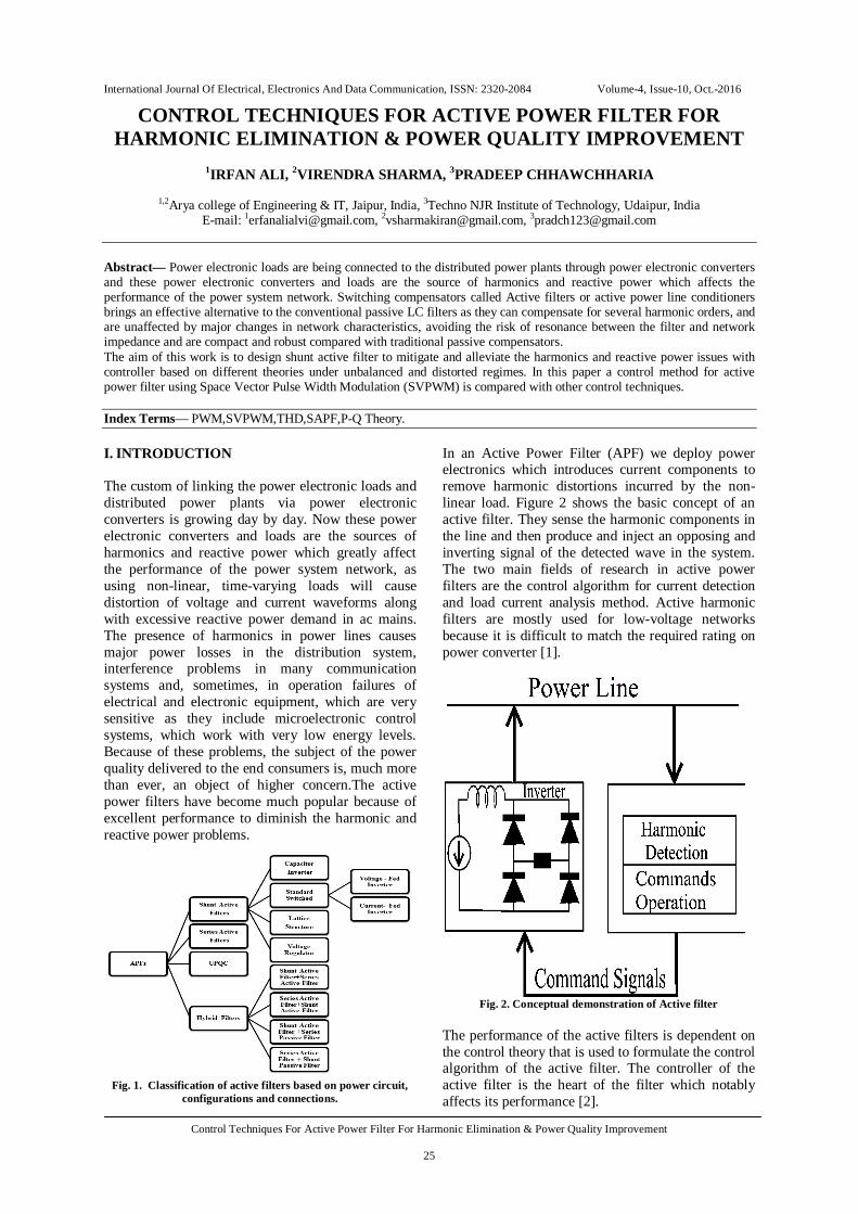
Fig. 1. Classification of active filters based on power circuit,
configurations and connections.
In an Active Power Filter (APF) we deploy power electronics which introduces current components to remove harmonic distortions incurred by the non-linear load. Figure 2 shows the basic concept of an active filter. They sense the harmonic components in the line and then produce and inject an opposing and inverting signal of the detected wave in the system. The two main fields of research in active power filters are the control algorithm for current detection and load current analysis method. Active harmonic filters are mostly used for low-voltage networks because it is difficult to match the required rating on power converter [1].
Fig. 2. Conceptual demonstration of Active filter
The performance of the active filters is dependent on the control theory that is used to formulate the control algorithm of the active filter. The controller of the active filter is the heart of the filter which notably affects its performance [2].
International Journal Of Electrical, Electronics And Data Communication, ISSN: 2320-2084 Volume-4, Issue-10, Oct.-2016
Control Techniques For Active Power Filter For Harmonic Elimination & Power Quality Improvement
26
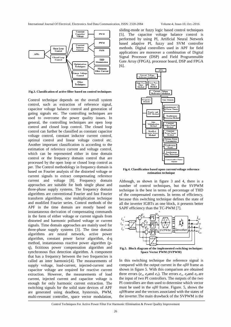
Fig.3. Classification of active filter based on control techniques Control technique depends on the overall system control, such as extraction of reference signal, capacitor voltage balance control and generation of gating signals etc. The controlling techniques are used to overcome the power quality issues. In general, the controlling techniques are open loop control and closed loop control. The closed loop control can further be classified as constant capacitor voltage control, constant inductor current control, optimal control and linear voltage control etc. Another important classification is according to the estimation of reference current and voltage control, which can be represented either in time domain control or the frequency domain control that are processed by the open loop or closed loop control as per. The Control methodology in frequency domain is based on Fourier analysis of the distorted voltage or current signals to extract compensating reference current and voltage [8]. Frequency domain approaches are suitable for both single phase and three-phase supply systems. The frequency domain algorithms are conventional Fourier and fast Fourier transform algorithms, sine multiplication technique and modified Fourier series. Control methods of the APF in the time domain are mostly based on instantaneous derivation of compensating commands in the form of either voltage or current signals from distorted and harmonic polluted voltage or current signals. Time domain approaches are mainly used for three-phase supply systems [3]. The time domain algorithms are neural network, active power algorithm, constant power factor algorithm, d-q method, instantaneous reactive power algorithm (p-q), fictitious power compensation algorithm and synchronous flux detection algorithm. A component that has a frequency between the two frequencies is called an inter harmonic[4]. The measurements of supply voltage, load-current, injected-current and capacitor voltage are required for reactive current extraction. However, the measurements of load current, injected current and capacitor voltage is enough for only harmonic current extraction. The switching signals for the solid state devices of APF are generated using deadbeat, hysteresis, PWM, multi-resonant controller, space vector modulation,
sliding-mode or fuzzy logic based control techniques [5]. The capacitor voltage balance control is performed by using PI, Artificial Neural Network based adaptive PI, fuzzy and SVM controller methods. Digital controllers used in APF for field applications are moreover a combination of Digital Signal Processor (DSP) and Field Programmable Gate Array (FPGA), processor board, DSP and FPGA [6].
Fig.4. Classification based upon current/voltage reference
estimation technique Although, as shown in figure 3 and 4, there is a number of control techniques, but the SVPWM technique is the best in terms of percentage of THD of the compensated currents. In terms of efficiency, because this switching technique defines the state of all the inverter IGBTs as one block, it presents better SAPF efficiency than the TC-PWM [7].
Fig.5. Block diagram of the implemented switching technique:
Space Vector PWM (SVPWM) In this switching technique the reference signal is compared with the output current in the αβ0 frame as shown in figure 5. With this comparison are obtained three errors (eα, eβand e0). The errors eα, eβand e0 are the input of two PI controllers. The outputs of the two PI controllers are then used to determine which vector must be used in the αβ0 frame. Figure. 5, shows the αβ0frame and the vectors associated with the states of the inverter.The main drawback of the SVPWM is the
International Journal Of Electrical, Electronics And Data Communication, ISSN: 2320-2084 Volume-4, Issue-10, Oct.-2016
Control Techniques For Active Power Filter For Harmonic Elimination & Power Quality Improvement
27
implementation complexity. Also, it needs more processing resources to execute all the tasks. This paper presents a design and implementation of suitable control strategy for shunt active power line conditioner. Suitable control techniques were developed to generate the reference currents from the distorted line current [9]. The following harmonic extraction controllers have been designed and compared for active power line conditioner. 1) Instantaneous real-power theory 2) Synchronous reference frame (SRF) theory The following techniques were developed and compared to generate the switching pulses for the inverter: 1) Hysteresis current controller technique. 2) PWM controller technique. 3) Space Vector PWM Controller technique. The THD of the source current is reduced to less than 5%, which complies with IEC 61000-3 and IEEE 519 harmonic standards. The modeling of the test electrical system and the passive and active filters has been carried out in the MATLAB/Simulink simulation software. This software is especially well suited when power electronics modeling is required. As well, it gives users the ability to build custom simulation modules that can be interfaced with the existing library models. This feature will be of particular importance when implementing the active filter control algorithm [11].
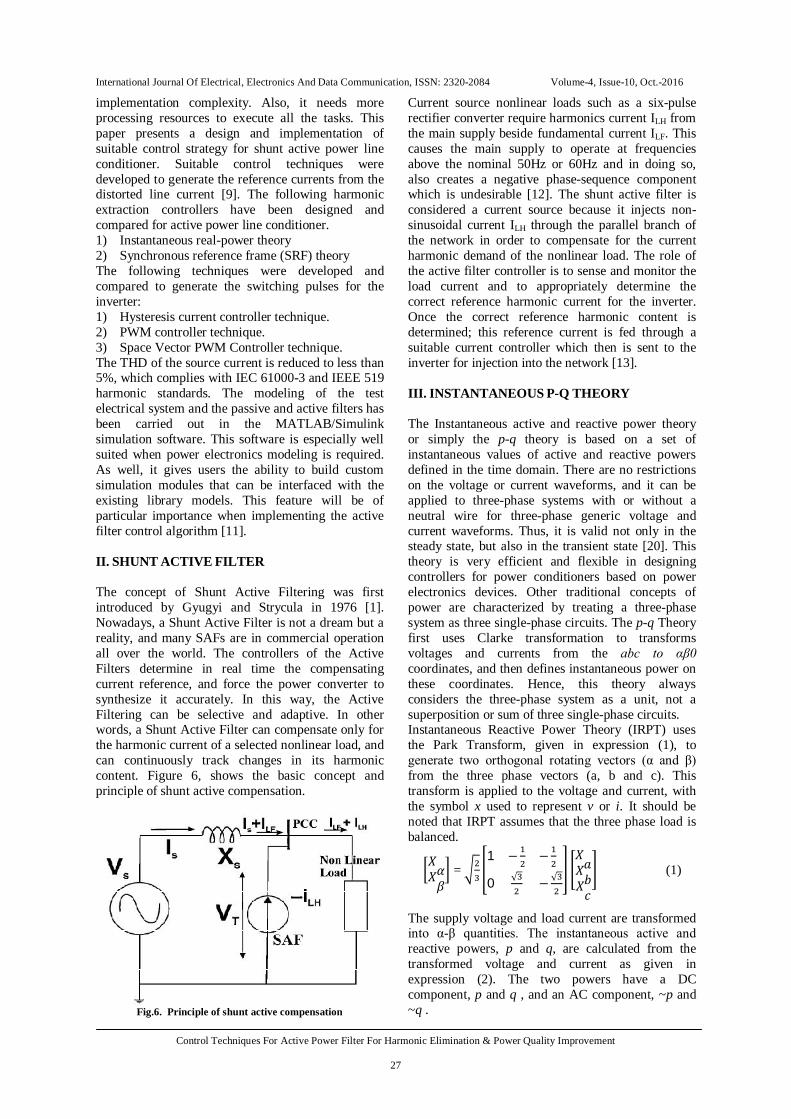
II. SHUNT ACTIVE FILTER The concept of Shunt Active Filtering was first introduced by Gyugyi and Strycula in 1976 [1]. Nowadays, a Shunt Active Filter is not a dream but a reality, and many SAFs are in commercial operation all over the world. The controllers of the Active Filters determine in real time the compensating current reference, and force the power converter to synthesize it accurately. In this way, the Active Filtering can be selective and adaptive. In other words, a Shunt Active Filter can compensate only for the harmonic current of a selected nonlinear load, and can continuously track changes in its harmonic content. Figure 6, shows the basic concept and principle of shunt active compensation.
Fig.6. Principle of shunt active compensation
Current source nonlinear loads such as a six-pulse rectifier converter require harmonics current ILH from the main supply beside fundamental current ILF. This causes the main supply to operate at frequencies above the nominal 50Hz or 60Hz and in doing so, also creates a negative phase-sequence component which is undesirable [12]. The shunt active filter is considered a current source because it injects non-sinusoidal current ILH through the parallel branch of the network in order to compensate for the current harmonic demand of the nonlinear load. The role of the active filter controller is to sense and monitor the load current and to appropriately determine the correct reference harmonic current for the inverter. Once the correct reference harmonic content is determined; this reference current is fed through a suitable current controller which then is sent to the inverter for injection into the network [13]. III. INSTANTANEOUS P-Q THEORY The Instantaneous active and reactive power theory or simply the p-q theory is based on a set of instantaneous values of active and reactive powers defined in the time domain. There are no restrictions on the voltage or current waveforms, and it can be applied to three-phase systems with or without a neutral wire for three-phase generic voltage and current waveforms. Thus, it is valid not only in the steady state, but also in the transient state [20]. This theory is very efficient and flexible in designing controllers for power conditioners based on power electronics devices. Other traditional concepts of power are characterized by treating a three-phase system as three single-phase circuits. The p-q Theory first uses Clarke transformation to transforms voltages and currents from the abc to αβ0 coordinates, and then defines instantaneous power on these coordinates. Hence, this theory always considers the three-phase system as a unit, not a superposition or sum of three single-phase circuits. Instantaneous Reactive Power Theory (IRPT) uses the Park Transform, given in expression (1), to generate two orthogonal rotating vectors (α and β) from the three phase vectors (a, b and c). This transform is applied to the voltage and current, with the symbol x used to represent v or i. It should be noted that IRPT assumes that the three phase load is balanced.
푋훼푋훽
= 1 − −
0 √ − √
푋푎푋푏푋푐
(1)
The supply voltage and load current are transformed into α-β quantities. The instantaneous active and reactive powers, p and q, are calculated from the transformed voltage and current as given in expression (2). The two powers have a DC component, p and q , and an AC component, ~p and ~q .

International Journal Of Electrical, Electronics And Data Communication, ISSN: 2320-2084 Volume-4, Issue-10, Oct.-2016
Control Techniques For Active Power Filter For Harmonic Elimination & Power Quality Improvement
28
푝 = Ṕ + P˜푞 = 푞´ + 푞˜ = 푣훼 푣훽
−푣훽 푣훼푖훼푖훽
(2)
By looking at instantaneous powers, the harmonic content can be visualized as a ripple upon a DC offset representing the fundamental power. By removing the DC offset with a suitable high pass filter [14], and then performing the Inverse Park Transform the harmonic current can be determined [4]. Figure.7 shows the block diagram for an active filter based on Instantaneous Reactive Power Theory. Filtering the instantaneous active and reactive powers leaves the AC components. The compensating currents are calculated by taking the inverse of equation (2), as shown by equation (3).
푖´훼푖´훽
= 푣훼 −푣훽푣훽 푣훼
푃˜푞˜ (3)
The inverse Park Transform is applied to i’α and i’β and this gives the harmonic currents in standard three-phase form, shown in equation. (4).
푖푎푖푏푖푐
=
⎣⎢⎢⎡
1 0− √
− − √⎦⎥⎥⎤ 푖´
훼푖´훽
(4)
Fig. 7. Block diagram for an IRPT based controller
IV. THE INSTANTANEOUS P-Q THEORY IN THREE PHASE THREE WIRE SYSTEMS Let us consider a three phase system with voltages va, vb, and vcare the instantaneous phase voltages and ia, ib, and icthe instantaneous line currents. Since zero sequence power in three phase three wire system is always zero, the equation (4) becomes:
푝푞 = 푣훼 푣훽
−푣훽 푣훼푖훼푖훽
(5)
In the proceeding discussion, the αβ currents will be set as functions of voltages and the real and imaginary powers p and q to explain the physical meaning of the powers defined in the p-q Theory. From (5), it is possible to write
푖훼푖훽
= 푣훼 −푣훽푣훽 푣훼
푝푞 (6)
If current and voltages from αβ variables are replaced to their equivalentabc variables in equation (6), the instantaneous imaginary power will be:
q= vαiβ -vβiα=√[vabic+ vbcia+ vcaib](7)
This expression is similar to that implemented in some instruments for measuring the three-phase
reactive power. The difference is that voltage and current phasors are used in those instruments. Here, instantaneous values of voltage and current are used instead. In terms of real and imaginary power, in order to draw a constant instantaneous power from the source, the Shunt Active Filter should be installed as close as possible to the nonlinear load, and should compensate the oscillating real power of this load. A three-phase system without neutral wire is being considered, and the zero-sequence power is zero [15]. Therefore, the compensator has to select the following powers as a reference to follow the control strategy. Instantaneous reactive power supplied by the compensator:
qc=−q (8) Instantaneous active power supplied by the compensator:
pc=−p’ (9) The mean value of oscillating active powers on α & β axis is zero but sum of both at every instant is not zero so capacitor has to supply energy when oscillating active power is positive and absorb energy when it is negative [16].
V. REFERENCE CURRENTS CALCULATION FOR THE COMPENSATOR The compensator reference currents in α-β domain can be calculated as:
푖∗푐훼푖∗푐훽
= 푣훼 −푣훽푣훽 푣훼
푝푞 (10)
In a-b-c domain currents will become:
푖∗푐푎푖∗푐푏푖∗푐푐
=
⎣⎢⎢⎡
1 0− √
− − √⎦⎥⎥⎤ 푖∗
푐훼푖∗푐훽
(11)
This operation takes place only under the assumption that the three-phase system is balanced and that the voltage waveforms are purely sinusoidal. If, on the other hand, this technique is applied to contaminated supplies, the resulting performance is proven to be poor [17].
Fig. 8. Shows the resulting algorithm for the calculation of reference currents of the compensator for the constant active
power supply

International Journal Of Electrical, Electronics And Data Communication, ISSN: 2320-2084 Volume-4, Issue-10, Oct.-2016
Control Techniques For Active Power Filter For Harmonic Elimination & Power Quality Improvement
29
VI. SYNCHRONOUS FRAME BASED ALGORITHM OR SYNCHRONOUS REFERENCE FRAME Bhattacharya et al [12], proposed using the DQ transform, given in equation (12), which changes the three conventional rotating phase vectors into direct (D), quadrature (Q) and zero (0) vectors. The fundamental component for each is now a dc value with harmonics appearing as ripple.
(12)
The synchronous frame method uses Park’s transformation to transform the three phase ac quantities into the synchronous rotating direct, quadrature and zero sequence components which are dc components and easy to analyzed [12]. The direct and quadrature components represent the active and reactive powers respectively. The higher order harmonics still remains in the system but can be eliminated by using high pass filters. The method is only applicable to 3-phase systems [24]. Harmonic isolation of the DQ transformed current signal is achieved by removing the DC offset with a high pass filter. Figure 9, illustrates the block diagram of the DQ active filter. Voltage information is not required for a Synchronous Reference Frame (SRF) based controller.
Fig. 9. Block diagram of the SRF based active filter controller.
One of the main differences of this method from p-q theory is that the d-q method requires the determination of the angular position of the synchronous reference of the source voltages; for this a PLL algorithm is used. After the transformation of load currents into the synchronous reference, a low-pass or high-pass filter is using to separate the fundamental and harmonic components. Finally, the reference currents are transformed to the three phase reference using the inverse synchronous transform [25].As with the IRPT method, SRF based filtering cannot cope with load imbalances. When the load is unbalanced there will be a 100Hz ripple on the D, Q and 0 terms. A 100Hz ripple is also present if third harmonic currents are present (the 150Hz is translated down to 100Hz). The source of the ripple cannot be determined if the load current contains triplen harmonics and is unbalanced [21]
VII. PWM TECHNIQUE The improvement of the semiconductor technology has given the opportunity to the application of power converters. The higher voltage and current rating and also better switching characteristic of the semiconductor components have expanded its utilization in wider area. Power converters are basically operated in the cut-off and saturation region, usually called ON-OFF region (no operation in the active region). This leads to the basic technique modulation called pulse width modulation (PWM) and becomes the basic of energy processing in converter system [26]. The energy that a switching power converter delivers to a motor is controlled by Pulse Width Modulated (PWM) signals applied to the gates of the power transistors. This is the most popular method of controlling the output voltage and this method is termed as Pulse-Width Modulation (PWM) Control. PWM signals are pulse trains with fixed frequency and magnitude and variable pulse width. There is one pulse of fixed magnitude in every PWM period. However, the width of the pulses changes from pulse to pulse according to a modulating signal. When a PWM signal is applied to the gate of a power transistor, it causes the turn on and turns off intervals of the transistor to change from one PWM period to another PWM period according to the same modulating signal. The frequency of a PWM signal must be much higher than that of the modulating signal, the fundamental frequency, such that the energy delivered to the motor and its load depends mostly on the modulating signal [29]. The advantage of PWM based switching power converter over linear power amplifier is:
Lower power dissipation Easy to implement and control No temperature variation and aging-caused
drifting or degradation in linearity Compatible with today’s digital micro-
processors VIII. SVPWM TECHNIQUE The well-known triangular carrier-based sinusoidal PWM for 3-phase converter was firstly proposed in 1964. Now, since the microprocessor based system develops very rapidly, the space vector modulation (proposed in 1982) became a basic modulation method in 3-phase PWM converter. SVPWM technique was originally developed as a vector approach to pulse width modulation for three-phase inverters. The SVPWM method is frequently used in vector controlled applications. In vector controlled applications this technique is used for reference voltage generation when current control is exercised. It is a more sophisticated, advanced, computation intensive technique for generating sine wave that provides a higher voltage with lower total harmonic
International Journal Of Electrical, Electronics And Data Communication, ISSN: 2320-2084 Volume-4, Issue-10, Oct.-2016
Control Techniques For Active Power Filter For Harmonic Elimination & Power Quality Improvement
30
distortion and is possibly the best among all the pulse width modulation techniques. It confines space vectors to be applied according to the region where the output voltage vector is located [26]. Because of its superior performance characteristics, it has been finding wide spread applications in recent years. The main aim of any modulation technique is to obtain variable output voltage having a maximum fundamental component with minimum harmonics. Many PWM techniques have been developed for letting the inverters to possess various desired output characteristics to achieve the wide linear modulation range, less switching losses, lower harmonic distortion [29] The SVPWM technique is more popular than conventional technique because of its excellent features. More efficient use of DC supply voltage. 15% more output voltage then conventional
modulation. Lower Total Harmonic distortion (THD). Prevent un-necessary switching hence less
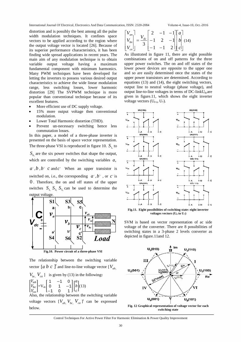
commutation losses. In this paper, a model of a three-phase inverter is presented on the basis of space vector representation. The three-phase VSI is reproduced in figure 10. ,1S to
,6S are the six power switches that shape the output, which are controlled by the switching variables ,a
,a ,b , ,,b c and ,c When an upper transistor is
switched on, i.e., the corresponding ,a , ,,b , or ,c is0 . Therefore, the on and off states of the upper switches ,1S ,3S ,5S can be used to determine the output voltage.
Fig.10. Power circuit of a three-phase VSI
The relationship between the switching variable vector a[ b c t] and line-to-line voltage vector [ ,abV
,bcV caV ] is given by (13) in the following: 푉푉푉
=Vdc
1 −1 00 1 −1−1 0 1
푎푏푐
(13)
Also, the relationship between the switching variable voltage vectors [ ,abV ,bcV caV ]t can be expressed below.
cba
V
VVV
dc
cn
bn
an
211121112
3(14)
As illustrated in figure 11, there are eight possible combinations of on and off patterns for the three upper power switches. The on and off states of the lower power devices are opposite to the upper one and so are easily determined once the states of the upper power transistors are determined. According to equations (13) and (14), the eight switching vectors, output line to neutral voltage (phase voltage), and output line-to-line voltages in terms of DC-linkUdcare given in figure.11, which shows the eight inverter voltage vectors (U0 to U7).
Fig.11. Eight possibilities of switching state: eight inverter
voltages vectors (U0 to U7) SVM is based on vector representation of ac side voltage of the converter. There are 8 possibilities of switching states in a 3-phase 2 levels converter as depicted in figure.11and 12.
Fig. 12 Graphical representation of voltage vector for each
switching state
International Journal Of Electrical, Electronics And Data Communication, ISSN: 2320-2084 Volume-4, Issue-10, Oct.-2016
Control Techniques For Active Power Filter For Harmonic Elimination & Power Quality Improvement
31
The graphic voltage vector representation in two axis system can be denoted in figure. 12. SVPWM refers to a special switching sequence of the upper power switches of a three-phase power inverter. It has been shown to generate less harmonic distortion in the output voltages and/or currents applied to the phases of a power system and to provide more efficient use of supply voltage compared with other modulation technique [30]. For the switching time at each sector, a MATLAB code is developed for generating the SVPWM pattern pulses. The code requires magnitude of the reference, the angle of the reference and the timer signal for comparison. The magnitude of the voltage reference as the first output and the angle of the reference as the second output from the control block are given to the developed code. The angle of the reference voltage is hold for each switching period so that its value does not change during time calculation. A ramping time signal is generated using repeating sequence block. IX. MODELLING OF SHUNT ACTIVE POWER FILTER 1 BASED ON P-Q THEORY The p-q theory model of figure 8, is modeled and is shown in the figure 13. The inputs to the p-q controller are the currents from the non-linear load and the source voltages. The outputs are the three phase reference currents that are send to the hysteresiscurrent controller where these currents are compared with the actual currents of the active filter to get the driving pulses of the inverter. The load currents and the source voltages are converted to αβ frame using equation (13). These currents and voltages in αβ frame are used to find the instantaneous powers using the equation (14) and are modeled in figure 13.
Fig. 13. Simulink model of the Shunt Active Power Filter 1
Connected to the network Figure. 13 shows how the active filter is connected to thepower system in the presence ofthe non-linear load. The very left is the unbalance and distorted distribution supply. At the very right, non-linear load has been connected to the system with the modeling of the load side commutation inductance. In the
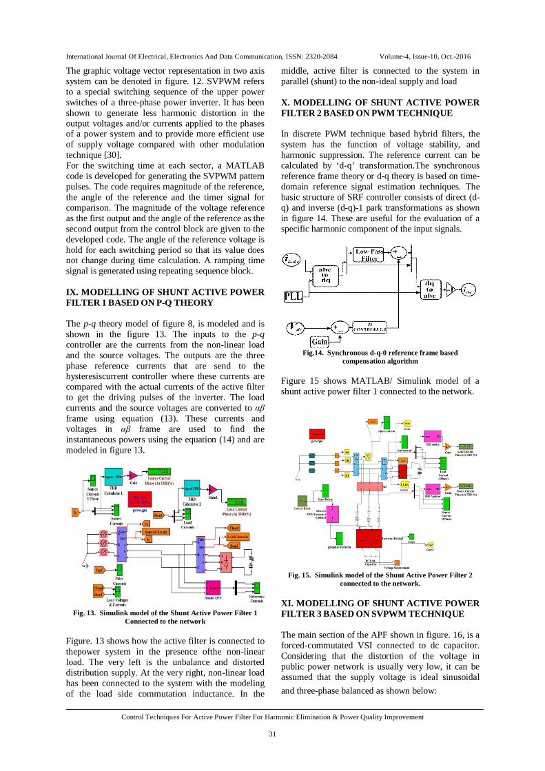
middle, active filter is connected to the system in parallel (shunt) to the non-ideal supply and load X. MODELLING OF SHUNT ACTIVE POWER FILTER 2 BASED ON PWM TECHNIQUE In discrete PWM technique based hybrid filters, the system has the function of voltage stability, and harmonic suppression. The reference current can be calculated by ‘d-q’ transformation.The synchronous reference frame theory or d-q theory is based on time-domain reference signal estimation techniques. The basic structure of SRF controller consists of direct (d-q) and inverse (d-q)-1 park transformations as shown in figure 14. These are useful for the evaluation of a specific harmonic component of the input signals.
Fig.14. Synchronous d-q-0 reference frame based
compensation algorithm Figure 15 shows MATLAB/ Simulink model of a shunt active power filter 1 connected to the network.
Fig. 15. Simulink model of the Shunt Active Power Filter 2
connected to the network. XI. MODELLING OF SHUNT ACTIVE POWER FILTER 3 BASED ON SVPWM TECHNIQUE The main section of the APF shown in figure. 16, is a forced-commutated VSI connected to dc capacitor. Considering that the distortion of the voltage in public power network is usually very low, it can be assumed that the supply voltage is ideal sinusoidal and three-phase balanced as shown below:

International Journal Of Electrical, Electronics And Data Communication, ISSN: 2320-2084 Volume-4, Issue-10, Oct.-2016
Control Techniques For Active Power Filter For Harmonic Elimination & Power Quality Improvement
32
32sin32sin
sin
tVvtVvtVv
ssc
ssb
ssa
(15)
Where sV is the supply voltage.It is known that the three-phase voltages [ ,saV ,sbV scV ]in a b c can
be expressed as two-phase representation in qd frame by Clark’s transformation and it is given by
sV =
sc
sb
sa
q
d
VVV
VV
23
230
21
211
32
(16)
It is possible to write equation (16) more compactly as
sssqsdscsbsas VjVVavavavV 210
32
(17)
Where
32j
ea , so balanced three-phase set of voltages is represented in the stationary reference frame by a space vector of constant magnitude, equal to the amplitude of the voltages, and rotating with angular speed f 2 .
Fig. 16. Configuration of a Hybrid APF using SVPWM As shown in figure.16, the shunt APF takes a three-phase voltage source inverter as the main circuit and uses capacitor as the energy storage element on the dc side to maintain the dc bus voltage dcV constant.
Fig.17. Control block diagram of proposed algorithm The figure 17, shows the block diagram of active filter controller implemented for reducing the harmonics with hybrid active filter system. In each
switching cycle, the controller samples the supply currents ,sai sci and the supply current sci is calculated with the equation of - (isa+isc), as the summation of three supply current is equal to zero. These three-phase supply currents are measured and transformed into synchronous reference frame (d-q axis) [26]. The fundamental component of the supply current is transformed into dc quantities in the (d-q) axis and the supply current amplitude si generated by the PI
controller with dcV and refV , the reference value of the dc bus voltage. The obtained d-q axis components generate voltage command signal. By using Fourier magnitude block, voltage magnitude and angle is calculated from the obtained signal. These values are fed to the developed code and compared with the repeating sequence. Then the time durations ,1T ,2T
and 0T ,the on-time of 1V , ,2V and 0V are calculated..
The generated switching actions are applied to the APF and power balancing of the filter takes place.
Fig. 18. Simulink model of the Shunt Active Power Filter 3
connected to the network. XII. SIMULATION RESULTS AND ANALYSIS The performance of the 3 proposed filters are evaluated using MATLAB/SIMULINK power tools. For an input supply voltage of 230V (rms) and switching frequency of 5 kHz, the simulation results before and after power balancing are shown. A. Performance of Shunt Active Power Filter 1 connected to a Non Linear Load. Figure 19 shows the connection of shunt active filter 1 to a non-linear load. The model is simulated in MATLAB and the output results are analyzed as discussed in the next section.

International Journal Of Electrical, Electronics And Data Communication, ISSN: 2320-2084 Volume-4, Issue-10, Oct.-2016
Control Techniques For Active Power Filter For Harmonic Elimination & Power Quality Improvement
33
Fig.19. Simulink Model ofShunt Active Power Filter 1 based on Instantaneous Reactive Power Theory with Hysteresis Current
Controller connected to a non – linear load
Fig. 20. Output load Voltage & Current waveforms
Fig. 21. Input source Current Waveform
The figures 20 and 21, shows the simulation results of three-phase nonlinear load with Filter1. Figure 20 shows the waveforms of load current after compensation and figure 21 shows the source current waveform after compensation.
Fig.22. Harmonic spectrums for nonlinear load condition with
Filter1 The figure 22, shows the current harmonic spectrum of three-phase nonlinear load with Filter1 after compensation. B. Performance of Shunt Active Power Filter 2 connected to a Non Linear Load. Figure 23 shows the simulation model of the shunt active power filter 2 connected to a non-linear load. The output load currents and input source currents are
obtained and a fourier analysis is done to observe the harmonic levels before and after compensation.
Fig.23. Simulink Model ofShunt Active Power Filter 2 based on PWM technique connected to a non -linear load.
Fig. 24. Output load Current waveforms
Fig.25. Input Source Current Waveform
The figures 24 and 25, shows the simulation results of three-phase non- linear load with Filter1. Figure 24 is the waveform of load current after compensation and figure 25 is the source current waveform after compensation.
Fig.26. Harmonic spectrums for nonlinear load condition with
Filter2
International Journal Of Electrical, Electronics And Data Communication, ISSN: 2320-2084 Volume-4, Issue-10, Oct.-2016
Control Techniques For Active Power Filter For Harmonic Elimination & Power Quality Improvement
34
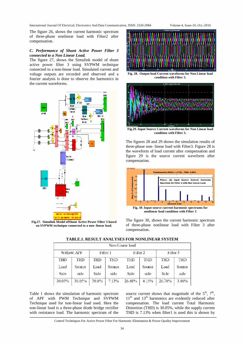
The figure 26, shows the current harmonic spectrum of three-phase nonlinear load with Filter2 after compensation. C. Performance of Shunt Active Power Filter 3 connected to a Non Linear Load. The figure 27, shows the Simulink model of shunt active power filter 3 using SVPWM technique connected to a non-linear load. Simulated current and voltage outputs are recorded and observed and a fourier analysis is done to observe the harmonics in the current waveforms.
Fig.27. Simulink Model ofShunt Active Power Filter 3 based
on SVPWM technique connected to a non -linear load.
Fig. 28. Output load Current waveforms for Non Linear load
condition with Filter 3.
Fig.29. Input Source Current waveforms for Non Linear load
condition with Filter 3. The figures 28 and 29 shows the simulation results of three-phase non- linear load with Filter3. Figure 28 is the waveform of load current after compensation and figure 29 is the source current waveform after compensation.
Fig. 30. Input source current harmonic spectrums for
nonlinear load condition with Filter 3 The figure 30, shows the current harmonic spectrum of three-phase nonlinear load with Filter 3 after compensation.
TABLE.1. RESULT ANALYSES FOR NONLINEAR SYSTEM
Table 1 shows the simulation of harmonic spectrum of APF with PWM Technique and SVPWM Technique used for non-linear load used. Here the non-linear load is a three-phase diode bridge rectifier with resistance load. The harmonic spectrum of the
source current shows that magnitude of the 5th, 7th, 11th and 13th harmonics are evidently reduced after compensation. The load current Total Harmonic Distortion (THD) is 30.05%, while the supply current THD is 7.13% when filter1 is used this is shown by
International Journal Of Electrical, Electronics And Data Communication, ISSN: 2320-2084 Volume-4, Issue-10, Oct.-2016
Control Techniques For Active Power Filter For Harmonic Elimination & Power Quality Improvement
35
figure 20 and 21, and the load current Total Harmonic Distortion (THD) is 26.48%, while the supply current THD is 4.15%, when filter 2 is used this is shown by figure 24 and 25. The load current Total Harmonic Distortion (THD) is 26.78%, while the supply current THD is 3.80%. when filter 3 is used this is shown by figure 28 and 29. It should be noted that the higher frequency harmonics caused by APF in mains current can be canceled easily by a small passive filter and there are
pulses in main current at the points, where dtdi of
load current is large, because fixed switching frequency restrict the tracking capability of APF. The harmonic spectrum shows that there is a reduction of higher order harmonics in three-phase source current when non-linear load is simulated using SVPWM technique in filter 3.
CONCLUSIONS The performance of three phase three wire shunt active filter with controller based on instantaneous active and reactive power (the p-q) theory, simulated in MATLAB/SIMULINK environment, is compared with PWM and SVPWM techniques, to compensate the problems of the harmonics and reactive power which are encountered from power electronic non-linear loads. The performance of the shunt active power filters is investigated under different scenarios. It is investigated that the p-q theory based active filter manages to compensate the harmonics and reactive power of the power distribution network even under unbalanced and distorted supply voltages. The active power filter is able to reduce the THD in source current at a level well below the defined standards specified by power quality standards. The THD in source current after the active filtering is not exactly zero. It is because internal switching of the compensator itself generates some harmonics. It has been noted that if voltage unbalance or distortion or both are present in the system, the simple p-q theory didn’t work well. Therefore, PWM and SVPWM control techniques are also observed and their performance are studied. The active power filter controller has become the most important technique for reduction of current harmonics in electric power distribution system. In this research work, three models for three-phase active power filter using three different control techniques, for balanced non-linear load are designed and simulated using MATLAB/Simulink software package for the reduction harmonics in source current. The conclusions of the research paper are such as: During this part of the research work the
performance of the hybrid active power filter is analyzed using PWM and SVPWM technique for minimizing harmonics, and improving the power factor in the power system.
The performance of the hybrid active power filter is verified with the simulation results. From the results; it clearly indicates that, the current ripple is less by using SVPWM compared to PWM.
In case of non-linear load, the THD response of the source current before compensation is 30.04%.
The THD response of PWM and SVPWM technique has been compared. The THD of the source current after compensation is 3.80% by using SVPWM technique. When using PWM technique the source current after compensation is 4.15% in case of nonlinear load.
The performance of SVPWM technique is better as compare to the PWM technique.
This research has given a broad review about the concept, theory and basic principle of multilevel inverter. After careful consideration between different modulation techniques, it is concluded that the space-vector-pulse-width modulation (SVPWM) is found to be most popular technique. The brief introduction of carrier based modulation technique is also discussed to get better understanding. While comparing the carrier based pulse width modulation and space-vector-pulse-width modulation, SVPWM carries better DC bus utilization causing a better production of fundamental component by means of amplitude. By implementing this technique, the amount of total harmonic distortion (THD) is also get reduced. The overview of each block used in this environment is also presented. The results obtained by utilizing practical values of R-L load. The harmonic contents at each output stage are analyzed by utilizing the FFT analysis tool which is incorporated in SimPowerSys tool box. REFERENCES
[1] L. Gyugyi and E. C. Strycula, “Active AC Power Filters,”
IEEE IIAS Annual Meeting, Cincinnati, 1976, pp. 529-535.
[2] Akagi, H.; Kanazawa, Yoshihira; Nabae, A., "Instantaneous Reactive Power Compensators Comprising Switching Devices without Energy Storage Components," in Industry Applications, IEEE Transactions on , vol.IA-20, no.3, pp.625-630, May 1984
[3] Akira Nabae, Satoshi Ogasawara, and Hirofumi Akagi, “A Novel Control Scheme for Current-Controlled PWM Inverters” IEEE Trans on IndustryApplications,Vol 1A-22, No.4, pp.562-570, July-1986
[4] Akagi, H.; Nabae, A.; Atoh, Satoshi, "Control Strategy of Active Power Filters Using Multiple Voltage-Source PWM Converters," in Industry Applications, IEEE Transactions on , vol.IA-22, no.3, pp.460-465, May 1986
[5] Giacoletto, L.J.; Park, G.L., "Harmonic filtering in power applications," in Industrial and Commercial Power Systems Technical Conference, 1989, Conference Record. , vol., no., pp.123-128, 7-11 May 1989
[6] Harmonics, P.S., "Power System Harmonics: An Overview," in Power Apparatus and Systems, IEEE Transactions on , vol.PAS-102, no.8, pp.2455-2460, Aug. 1983
[7] S. Bhattacharyya, S. Cobben, P. Ribeiro and W. Kling “Harmonic emission limits and responsibilities at a point
International Journal Of Electrical, Electronics And Data Communication, ISSN: 2320-2084 Volume-4, Issue-10, Oct.-2016
Control Techniques For Active Power Filter For Harmonic Elimination & Power Quality Improvement
36
of connection” IET Gener. Transm.Distrib., Vol. 6, No. 3, pp. 256–264, March-2012
[8] Regulation, supervision bureau for the water, and electricity sector of the Emirate of Abu Dhabi. “Limits for harmonics in the electricity supply system”. 2005.
[9] SEC. “The Saudi Arabian grid code”, 2007. [10] Gyu-ha Choe, Min-Ho Park, S, “Analysis and Control of
Active Power Filter with Optimized Injection,” IEEE Trans. Power Electron., vol.4, No.4, Oct 1989 pp. 427-433.
[11] Holtz, J., "Pulsewidth modulation-a survey," in Power Electronics Specialists Conference, 1992. PESC '92 Record., 23rd Annual IEEE , vol., no., pp.11-18 vol.1, 29 Jun-3 Jul 1992
[12] S. Bhattacharya, D. M. Divan and B. B. Banerjee, “Control and reduction of terminal voltage total harmonic distortion (THD) in a hybrid series active and parallel passive filter system," in Power Electronics Specialists Conference, 1993. PESC '93 Record., 24th Annual IEEE , vol., no., pp.779-786, 20-24 Jun 1993.
[13] Watanabe, E.H.; Stephan, R.M.; Aredes, M., "New concepts of instantaneous active and reactive powers in electrical systems with generic loads," in Power Delivery, IEEE Transactions on , vol.8, no.2, pp.697-703, Apr 1993
[14] Pahmer, C.; Capolino, G.A.; Henao, H., "Computer-aided design for control of shunt active filter," in Industrial Electronics, Control and Instrumentation, 1994. IECON '94., 20th International Conference on , vol.1, no., pp.669-674 vol.1, 5-9 Sep 1994.
[15] Fang Zheng Peng; Jih-Sheng Lai, "Generalized instantaneous reactive power theory for three-phase power systems," in Instrumentation and Measurement, IEEE Transactions on , vol.45, no.1, pp.293-297, Feb 1996
[16] Nabae, A.; Tanaka, T., "A new definition of instantaneous active-reactive current and power based on instantaneous space vectors on polar coordinates in three-phase circuits," in Power Delivery, IEEE Transactions on , vol.11, no.3, pp.1238-1243, Jul 1996
[17] Aredes, M.; Hafner, J.; Heumann, K., "Three-phase four-wire shunt active filter control strategies," in Power Electronics, IEEE Transactions on , vol.12, no.2, pp.311-318, Mar 1997
[18] Singh, Bhim; Al-Haddad, K.; Chandra, A., "A review of active filters for power quality improvement," in Industrial Electronics, IEEE Transactions on , vol.46, no.5, pp.960-971, Oct 1999
[19] Ambrish Chandra, Bhim Singh, and B. N. Singh, M “An Improved Control Algorithm of Shunt Active Filter for Voltage Regulation, Harmonic Elimination, Power-Factor Correction, and Balancing of Nonlinear Loads,” IEEE Trans. Power Electron., vol.15, No.3, May 2000.
[20] Mendalek, N.; Al- Haddad, K.; Dessaint, L.A.; Fnaiech, F., "Nonlinear control strategy applied to a shunt active power filter," in Power Electronics Specialists Conference, 2001. PESC. 2001 IEEE 32nd Annual , vol.4, no., pp.1877-1882 vol. 4, 2001 ,IEEE Proceedings-, Volume 147, Issues: 5, Pages: 403-415, September 2000.
[21] João Afonso, Carlos Couto, Júlio Martins, “Active Filters with Control Based on the p-q Theory”, IEEE Industrial Electronics Society Newsletter Sept. 2000.
[22] Afonso, Joao L., Henrique Jorge de Jesus Ribeiro da Silva, and Júlio S. Martins. "Active filters for power quality improvement." 2001 IEEE Porto PowerTech, 10-13 Set. 2001, Porto, Portugal.
[23] Turunen, J.; Salo, M.; Tuusa, H., "Comparison of series hybrid active power filters based on experimental tests," in Power Electronics and Applications, 2005 European Conference on , vol., no., pp.10 pp.-P.10, 11-14 Sept. 2005
[24] S. Sirisukprasert, J.S. Lai, and T.H. Liu. “Optimum harmonic reduction with a wide range of modulation indexes for multilevel converters”. Industrial Electronics, IEEE Transactions on, 49(4):875–881, 2002.
[25] Hirofumi Akagi “Active Harmonic Filters” Proceedings of the IEEE, Vol. 93, No. 12, pp.2128-2141, Dec-2005.
[26] L.G. Franquelo, J. Napoles, R.C.P. Guisado, J.I. Leon, and M.A. Aguirre. “A flexible selective harmonic mitigation technique to meet grid codes in three-level PWM converters”. Industrial Electronics, IEEE Transactions on, 54(6):3022–3029, 2007.
[27] Ohnishi, Tokuo, and Hiroshi Okitsu. "A novel PWM technique for three-phase inverter/converter." B 105.2 (1985): 176-183.
[28] Dehini, Rachid, AbdesselamBassou, and BrahimFerdi. "The harmonics detection method based on neural network applied to harmonics compensation." International Journal of Engineering, Science and Technology 2.5 (2010): 258-267.
[29] João O. P. Pinto, Bimal K. Bose, “A Stator-Flux-Oriented Vector-Controlled Induction Motor Drive With Space-Vector PWM and Flux-Vector Synthesis by Neural Networks”, IEEE Trans. Power Electron., vol. 37, no. 5, Sept/Oct. 2001, pp. 1308-1318.
[30] Das, J.C., "Passive filters-potentialities and limitations," in Pulp and Paper Industry Technical Conference, 2003. Conference Record of the 2003 Annual , vol., no., pp.187-197, 16-20 June 2003
[31] Hirofumi Akagi, Edson Hirokazu Watanabe and Mauricio Aredes “Instantaneius power theory and applications to power conditioning” IEEE press, 2007
[32] Hasan, K.; Romlie, M.F., "Comparative study on combined series active and shunt passive power filter using two different control methods," in Intelligent and Advanced Systems, 2007. ICIAS 2007. International Conference on , vol., no., pp.928-933, 25-28 Nov. 2007
[33] ShahriyarKaboli, JavadMahdavi, S, “Application of Random PWM Technique for Reducing the Conducted Electromagnetic Emissions in Active Filters,” IEEE Trans. Power Electron., vol.54, No.4, Aug 2007 pp. 2333-2343.
[34] Rajendra R. Sawant, and Mukul C. Chandorkar, M, “A Multifunctional Four-Leg Grid-Connected Compensator”, IEEE Trans. Power Electron., vol.45, No.1, Jan./Feb 2009 pp 249-259.