aco building drainage · aco building drainage. lifting plants pumping stations grease separators...
TRANSCRIPT
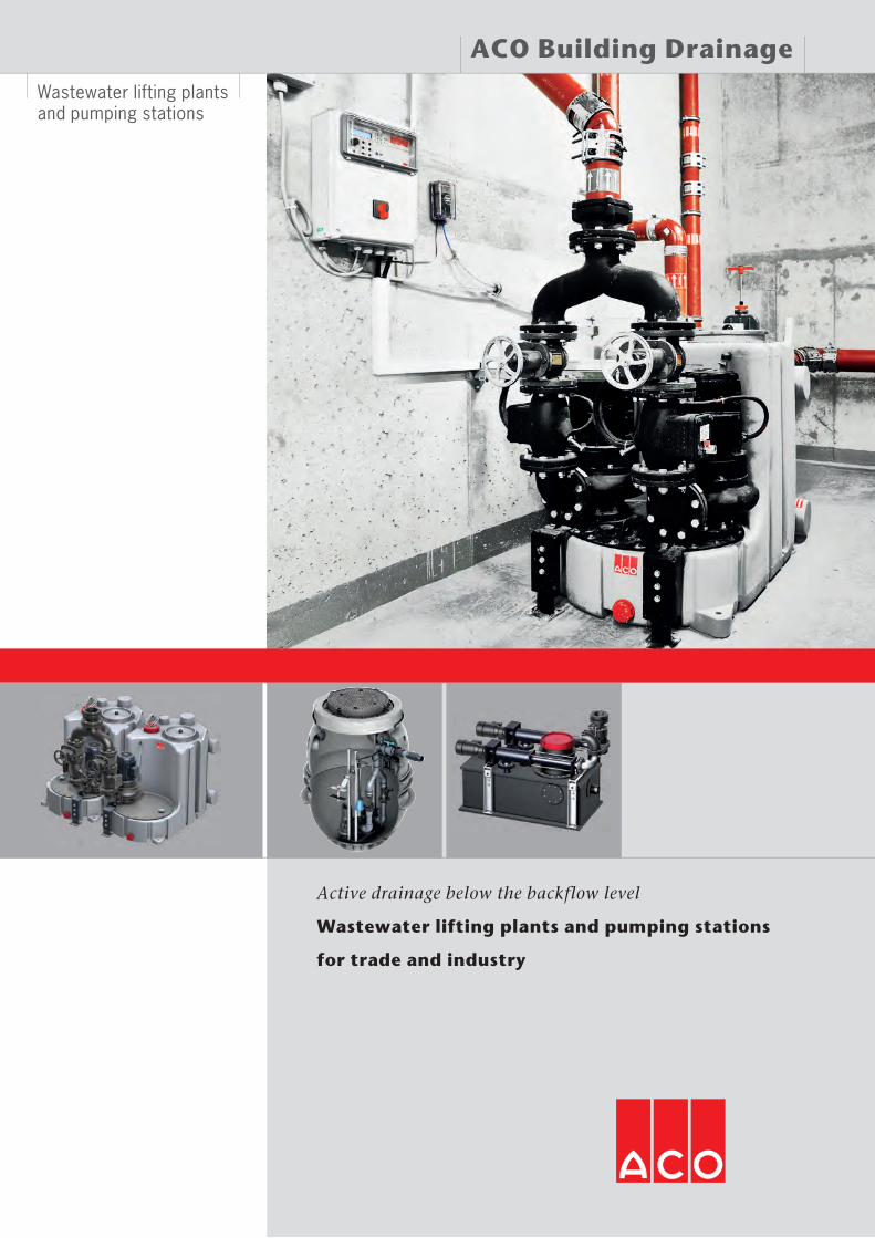
Wastewater lifting plants and pumping stations
for trade and industry
Active drainage below the backflow level
Wastewater lifting plants and pumping stations
ACO Building Drainage

Lifting plants Pumping stations
Grease separators Starch separators Light oil separators Process engineering
Backflow systems Floor drainage Bathroom drainage Roof drainage Parking deck drainage Balcony and terracedrainage
Pipe systems
collect: Collect and carry
release: Pump, discharge andreuse
clean: Pretreat and treat
hold: Hold and retain
ACO. The future of drainage.
The ACO system chain creates the drainage solutions for the environ-mental conditions of tomorrowIncreasingly extreme weather events require ever more complex drainage concepts.To this end, ACO creates clever system solutions, which function in both directions:They protect people from water – and vice versa.Each ACO product within the ACO system chain secures the route of the water with the objective of being able to recover it in a way that makes ecological and economic sense. Within the ACO Group, ACO Building Drainage supports the global system chain and combines system solutions for drainage, separation and pumping to form integrated drainage concepts within buildings.
ACO system chain in action

ACO system chain in action
Contents
Products for all requirements 04
Basic Principles and Technical Information 06
Causes and risks due to backflow 06
Dimensioning tools for wastewater lifting plants and pumping sta- 08
Layout and calculation 10
Installation instructions for lifting plants 12
Wastewater Lifting Plants - Product Overview 15
Muli-Mini duo lifting plantfor freestanding installation 16
Muli-Star DDP wastewater lifting plant for freestanding installation 18
Muli-PE-S duo wastewater lifting plant for freestanding installation 20
Muli Pro-PE K duo wastewater lifting plant for freestanding installation 22
Muli Pro-PE V duo wastewater lifting plant for freestanding installation 24
Muli Pro-PE K Parallel wastewater lifting plant for freestanding installation 26
Muli Pro-PE V Parallel wastewater lifting plant for freestanding installation 28
Muli Pro 1.x VA duo wastewater lifting plant for freestanding installation 30
Muli Pro 2.x VA duo wastewater lifting plantfor freestanding installation 32
Muli Pro-PE N XL duo wastewater lifting plantfor freestanding installation 34
Upstream tank plants 36
Lifting plants, system solutions for grease separators 37
Pumping Stations Product Overview 45
Basic Principles and Technical Information 46
Protection against backflow 46
Layout and design 47
State-of-the-art 48
Backflow-proof installation 49
Product version 51
Muli-Max-F mono/duo prefabricated pumping station 54
Powerlift - P duo prefabricated pumping station 60
Powerlift mono/duo pump kit 62
Submersible pumps 64
ACO service advantages 74
ACO 360° service – everything from a single stop 75

4
Supermarkets and shopping centresYou will find ACO lifting plants and pumping stations in drainage systems for supermarkets and shopping centres through to large shopping malls. The product range covers different application; on the one hand upstream and downstream of
Catering establishmentsIn commercial kitchens large quantities of greasy wastewater is produced by the cleaning of pots, dishes and other kitchen equipment items. Special lifting plants are required to pump the treated wastewater out of the grease separator and into the sewers; these lifting plants can easily pump the aggressive
Products for all requirements
grease separators for catering establishments and on the other hand as variants for faecal wastewater in the sanitary installations of highly frequented shopping malls.
kitchen wastewater. This mainly applies to hotels, refectories, canteens, motorway service areas and hospitals as well as res-taurants in shopping centres, and kitchens where large quanti-ties of food are grilled, fried or deep-fat fried.

5
Products for all requirements
Trade and industryPumping stations are suitable for draining large outdoor areas (e.g. ramps and inner courtyards). Due to their large usable volume they are also ideally suitable for use downstream of large-volume grease separators. In commercial units with many
Rainwater, grey and black water, which arises below the backflow level must be fed without backflow into the public sewers via an automatically operating lifting plant or pumping station. This basic principle applies to detached houses precisely in the same way as it does to public buildings or industrial
employees, by choosing different pump types, faecal waste-water can also be transported. Pumping stations are frequently used where it is structurally not possible to install freestanding wastewater lifting plants.
plants. The objective when designing a drainage system is "to guide surface water away from the building and not to direct it into thebuilding". Accordingly, rainfall runoff and outdoor areas must be drained via separate pumping stations outside the building.
Active backflow protection for all types of building
6
How does backflow occur?
Public sewers sized to EN 12056-4 are designed for average rainfall events only, for purely economic reasons, and not for extreme events such as heavy rainfall. Heavy precipitation overloads the sewers and the backflowing water rises in the sewer manholes up to the backflow level. To the same extent, the backflowing wastewater pushes back into the plot drainage system of the surrounding houses.
Causes of backflowApart from heavy rainfall, the following events are also responsible for backflow:
Sewer blockage or pipe bursts Sewer damage, e.g. cross-section
reduction due to root growth Loss of operation in the pumping sta-
tions of the sewer operator, if the plot drainage is connected to it
Unscheduled discharge, e.g. during sewer flushing or fire service deploy-ments
Increased wastewater inflow due to additional connections (e.g. extension of residential areas)
An exceptional phenomenon?It does not always have to be a thousand year flood like the flooding of the River Elbe in 2002. In the summer of 2015, many regions in Germany were also affected by heavy rainfall events, the sewers were overloaded and many base-ments were flooded. Meteorologists agree that floods and extreme rainfall events will continue to increase throughout Europe.
Annual damage amounting to millions – the question of liability and compensation
Municipalities are not liableIn May 2004, the Bundesgerichtshof, the German Federal High Court, issued a decisive judgement: Municipalities are not liable in the event of a completely unusual and rare, disastrous rainfall event. As there is no fixed "rain limit", many municipalities take the precaution of specifying in their byelaws that devel-opers and home owners are responsible for protecting their properties against backflow and flooding. I.e. home owners must pay for backflow damage them-selves. The municipalities cannot be made liable.
Insurance companies pay only conditionallyApart from damage to private property, house owners are also liable to their ten-ants. There are now insurance offers
which deal with the problem of backflow. However, if the structural measures are not carried out correctly or even not at all, the insurers largely refuse liability in the event of water damage due to back-flow.
Building contents insurance: A normal building contents or building insurance does not cover damage due to floods and heavy rainfall events or resulting backflow.
Storm and tempest damage insurance: If, in addition to their building contents or building insurance, the insured person has extended insurance protection to include storm and tempest damage, they are insured in the event of damage due to force majeure or acts of nature, for example, flooding, landslide, earthquake.
Important!The risk of backflow is not automatically included in storm and tempest insurance and must be taken out separately! Insurance protection only exists if safety precautions such as backflow stops or lifting plants are installed for discharge points below the backflow level and these are kept operational.
Basic principles

7
Protection against backflow
The greatest possible protection against backflow can be achieved by a wastewater lifting plant whose pressure line, as in these two examples, has been routed above the backflow level.
Backflow level
Protection against backflow in gradient to the sewer provided by a wastewater lifting plant in multiple unit dwellings, commercial properties and detached houses with granny flat
Protection against backflow if the sewer is higher than the sanitary appliances
Location of the drainage points for connection to a wastewater lifting plant
Wastewater from drainage points below the backflow level, according to EN 12056, must be fed, backflow-free, into the public sewers via an automatically operating lifting plant. In addition, the following basic rule applies to rainwater from areas below the backflow level: Sur-
Overview of relevant standards
Part1: Lifting plants for wastewatercontaining faecal matter
Part 2: Wastewater lifting plants for non-faecal wastewater
Part 3: Lifting plants for limited appli-cations
Part 4: Non-return valves for faecal-free wastewater and wastewater containing faecal matter
Part 1: Legal and technical provisions
Part 5: Backflow safety valve and light liquid closures
EN 12050, Published 05/2015Wastewater lifting plants for buildings and sites
EN 12056, Published 01/2001Gravity drainage systems inside buildingsPart 1: General and performance
requirementsPart 2: Sanitary pipework, layout and
calculationPart 4: Wastewater lifting plants –
Layout and calculationPart 5: Installation and testing, instruc-
tions for operation, maintenance and use
Work contractAs EN 12056 covers all wastewater installations in the area up to and includ-ing the outer envelope of the building, and DIN 1986-100 also covers the area of the site up to and including the site boundary (in Europe EN 752 applies from the outer building envelope up to the connection to the sewer in the road), in case of a contract award, the work contract must define the standard to which the wastewater system is to be designed and built.
EN 12050 is the product standard for wastewater lifting plants. The applica-tion areas and construction and testing principles for the respective versions/components are defined in four parts.
Basic principles
face water must be guided away from the building and not drawn into the building. Accordingly, rainfall runoff areas must be drained via separate pumping stations outside the building. All drainage points located above the back-flow level must be drained with a natural
slope (gravity principle). The wastewater from these sanitary appliances may only be discharged via wastewater lifting plants in absolutely necessary exceptional cases (renovation of old buildings).

■ Calculation according to known total delivery rate Here the delivery rate or capacity is predefined or known and can be entered directly. Multiple input is possible without any problems.
■ Calculation according to residen-tial units / residents If precise information on the sanitary appliances on site is not available, the max. flow rate can be calculated
Basic principles
Dimensioning tool Wastewater lifting plants and pumping stations
In the past, many manual calculations were required to find the suitable lifting plant or pumping station for a project. The pressure head losses were calcu-lated individually with the help of diverse tables and diagrams, for example, depending on the pressure pipe dimen-sion and flow rate. This procedure is very time consuming and requires the user to have a lot of experience. A change in a parameter frequently meant a complete revision of the design.With the dimensioning tool for waste-water lifting plants and pumping stations of ACO Building Drainage, these manual calculations are a thing of the past. The tool performs the calculations in real time and presents the results clearly and traceably.
Use conditionsThe user has the choice between three types of design:
In the next step the individual resistanc-es must be entered. If it is not clear how many bends will be installed later, estimated values can also be used. Under the bottom line, more bends always means more losses. The final step involves entering the pres-sure line material and other information on the pressure line (pipe). "Standard" pipe roughness is the worst case calculation, a plastic pipe has low
Individual resistances and pressure line
http://catalogue.aco-haustechnik.de/en/Home/Dimensioning-tools
roughly according to the number of residents. This calculation is very roughly estimated, however it can be refined by entering the daily wastewa-ter quantity per resident.
■ Calculation according to sanitary appliances This is the most frequently used calculation. In the first step the user enters known delivery flows, e.g. flow rate of a grease separator. The type
of use is then entered to define how frequently the sanitary appliances are used; for example a department store will expect more passing trade than a detached house; the wastewater flow rate is far higher in the department store. The calculation is always based on the extreme case: All sanitary units are in use at the same time.
roughness and thus less losses. The pipe dimension to be chosen determines which plant type can be selected later, small cross-sections allow only a very limited choice of faecal lifting plants. The length of the pressure line in turn de-termines how high the pressure losses are; here too an "estimated value" can be used if precise information is not available. The geodetic delivery head, also called Hgeo, describes the level difference
between the switching off point of the pump and backflow loop. Above this level difference the pump must lift the wastewa-ter vertically, it should then ideally be able to flow into the drain pipe itself by free fall. Hgeo is a system constant that cannot be changed, it is therefore plotted on the y axis as the starting point for the systemcharacteristic curve.
8
Backflow stops
9
Clarifying the preconditions
Designing the plant ■ Wastewater inflow (connection values) ■ Total delivery head (Hgeo) ■ Calculation of the pump operating point
■ Selection of the pressure line nominal size
■ Selection of the valves and fittings required
■ Checking the minimum flow velocity
■ Calculation the usable tank volume ■ Shaft definition ■ Ventilation line
The pumps are designed and dimensioned in accordance with EN 12056-4. Here the total delivery head and the total inflow are determined. A pump must be selected for the deter-mined values, which at its operating point at least achieves the determined delivery head and the delivery performance (taking into account the minimum flow velocity 0.7 m/s, max. 2.3 m/s).
Selecting the plant ■ Single or twin lifting plant, EN 12056-4: A twin lifting plant must be installed in systems in which the wastewater inflow must not be inter-rupted.
SelectionThe calculations are clearly shown on this summary page. These include the pressure losses which are later added to Hgeo.
Htot = Hgeo + H(V,A) + H(V,R)
Total delivery head = geodetic delivery head + losses in valves and fittings + losses in pipes
The theoretical operating point is a combination of the minimum flow rate and the minimum delivery head, where the minimum delivery head is set as the calculated total delivery head. The minimum flow rate is equal to the inlet flow rate, however, an additional check is made whether this also fulfils the re-quirements for a minimum flow velocity in the pressure line of 0.7 m/s. If not, this value is replaced by the calculated minimum flow rate. According to the standard the minimum flow rate of the pump must always be designed so that it is larger or equal to the inflowing wastewater (input flow rate <= delivery flow at the operating point).
When choosing the model, ensure that the actual operating point is larger than the theoretical operating point, i.e. the lifting plant can pump more water than necessary. It thus still has reserves. There is no generally valid statement regarding the choice. The user should select several pumps and which model suits best. The choice of usable volume, depending on the selected inlet, is im-portant for the 3rd calculation step.The technical parameters (kW output and rpm) are shown here. The number of switching cycles per pump and hour can be calculated from the values entered previously.
A target-actual comparison is used here. The pump should not start up too frequently each hour; this leads to increased wear. A large pump with 7.5 kW and 1450 rpm, for example, should only start up a maximum 30 times an hour, while a small pump with 1.5 kW and 1450 rpm can start up approx. 80 times an hour without becoming exces-sively hot or wearing. An increase in the usable volume or choice of a smaller pump influences the switching frequency considerably.If no further indications appear, click "Product details" to jump directly to the corresponding online catalogue page or click Summary to create a PDF of the design.
Installation space ■ In the building ■ In the ground, outside ■ Backflow level ■ Pumped medium ■ Discharge conditions in the sewer
Power supply ■ 230/400 V ■ Mains frequency 50 Hz
■ Delivery head and pipe routing (distance from the sewer)
■ Type of individual resistances (bends, stop valves, etc.)
■ Dimension
In the case of tank systems attention is paid to ensuring that the usable tank volume is greater than the volume in the pressure line. By complying with this requirement in EN 12056-4, the contents of the pressure line is completely replaced with each pump operation. The following notes should be followed when dimensioning the usable volume: Pumps or lifting plants are usually
designed for S3 (intermittent operation), i.e. after switching on the pump, after the pumping operation has ended a sufficiently long pump standstill time must be available (for the motor to cool).
■ Selecting the pump ■ Selecting the controls and accessories

10
Technical Information
Layout and calculation
Which type of wastewater is produced?
ACO MultiControl
WastewaterWastewater is the term used to describe any type of contaminated water pro-duced in households or on commercial properties. It includes rainwater, water soiled by use, commercially used water, etc.Domestic wastewaterDomestic wastewater is a mixture of drinking water, organic and inorganic substances in solid and in dissolved form. From experience, the substances that occur in wastewater from house-holds mainly include human faeces, hair, food waste, cleaning products and deter-gents and various types of chemicals, paper, cloths and sand (e.g. in combined systems due to rainwater scouring).
The ACO MultiControl control series has been used in different ACO products for many years and with a very positive response. A differentiation is made between two product series: ACO MultiControl for lifting plants and ACO MultiControl for pumping stations.The MultiControl for wastewater lifting plants is used in almost all ACO lifting plants. Among other things, this pro-duces many advantages for the service department. The customer service department does not have to spend a long time familiarising itself with a new control in the plant and is directly famil-iar with the one installed. The control has an illuminated display, via which all operating states can be read off in plain text, and parameters can be read out and changed. The most recent errors can be easily queried via the plain text display and make it easier to find the error in case of a service call-out. The switching points of the pump can be read out easily and changed if required using the rotary knob. The installed ServiceMode prevents acciden-tal changing of the parameters. The operating hours and an integrated switching on counter allow conclusions
to be drawn about the actual or worn condition of the pumps. Thus pumps are frequently replaced by way of precau-tion after a certain running time, to act before a failure can occur. An integrated amperemeter displays the consumed current while the pump is running and switches off the pumps as a precaution if the current consumption is too high. An enhanced version of the MultiControl is used for pumping stations. In addition to the functions named above it has other useful features. These include connection options for up to four float switches, a 4 – 20 mA pressure pick-up or the backpressure bell supplied. These options give the user free choice when it comes to measuring the level in the tank. If the 4 – 20 mA pressure pick-up is connected the level can also be trans-mitted to the building control system as a 4 – 20 mA or 0 – 10 V signal, so that the water level in various pumping stations is always in view. To satisfy explosion protection require-ments, if the 4 – 20 mA pressure pick-up is used in black water the explosion barrier (accessory) is required. The inte-grated ATEX mode prevents the pumps from being able to be switched on if the
level falls below the switching off level, in order to prevent flying sparks on the impeller of the pump.In addition to the fixing material and 9 V block the scope of supply includes the backpressure bell with 10 m control line.Two versions are available with both isolated and non-isolated (230 V) alarm outputs. These can be forwarded to the building control system or directly to a horn or warning light. A separate 230 V connection is not required for this.There is no differentiation between low price and expensive plant models; the MultiControl fulfils all requirements in all application areas. Controls are used for 230 V (alternating current), and 400 V (three-phase current).
However, experience also shows that all waste which is added to the system due to ignorance or failure to follow the regulations then has to be discharged through the sanitary appliance. This should always be avoided! Grey waterNon-faecal wastewater-Black waterFaecal wastewater.RainwaterUnused rainwater, which is merely soiled by air pollution, contamination due to dirt on the runoff surface. The degree of contamination primarily depends on geography, proximity to a city (air and surface soiling) and rainfall frequency. Contaminations frequently contain oil, salt or sand.
Industrial wastewater (= process water)Industrial wastewater requires a detailed analysis of the medium, as the chemical substances in it can vary widely and therefore constitute a risk to the instal-lation. Corrosion damage is observed most frequently. Particular attention should be paid to wastewater from the textile and food industry. Impeller type (e.g. blockaging), shaft dimensioning (due to highly different discharges) and material combinations (e.g. corrosion) of the installation are the central critical points here.
11
Technical information
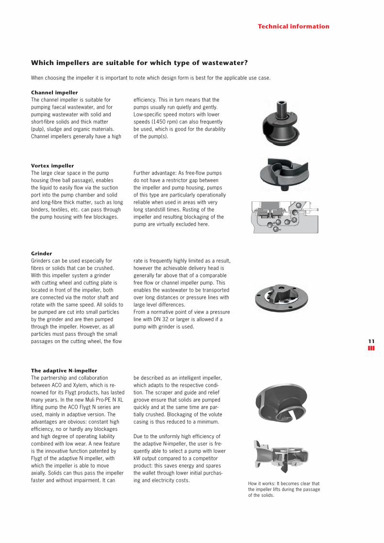
Which impellers are suitable for which type of wastewater?
When choosing the impeller it is important to note which design form is best for the applicable use case.
Channel impeller
Vortex impeller
Grinder
The adaptive N-impeller
The channel impeller is suitable for pumping faecal wastewater, and for pumping wastewater with solid and short-fibre solids and thick matter (pulp), sludge and organic materials. Channel impellers generally have a high
The large clear space in the pump housing (free ball passage), enables the liquid to easily flow via the suction port into the pump chamber and solid and long-fibre thick matter, such as long binders, textiles, etc. can pass through the pump housing with few blockages.
Grinders can be used especially for fibres or solids that can be crushed. With this impeller system a grinder with cutting wheel and cutting plate is located in front of the impeller, both are connected via the motor shaft and rotate with the same speed. All solids to be pumped are cut into small particles by the grinder and are then pumped through the impeller. However, as all particles must pass through the small passages on the cutting wheel, the flow
The partnership and collaboration between ACO and Xylem, which is re-nowned for its Flygt products, has lasted many years. In the new Muli Pro-PE N XL lifting pump the ACO Flygt N series are used, mainly in adaptive version. The advantages are obvious: constant high efficiency, no or hardly any blockages and high degree of operating liability combined with low wear. A new feature is the innovative function patented by Flygt of the adaptive N impeller, with which the impeller is able to move axially. Solids can thus pass the impeller faster and without impairment. It can
How it works: It becomes clear that the impeller lifts during the passage of the solids.
efficiency. This in turn means that the pumps usually run quietly and gently. Low-specific speed motors with lower speeds (1450 rpm) can also frequently be used, which is good for the durability of the pump(s).
Further advantage: As free-flow pumps do not have a restrictor gap between the impeller and pump housing, pumps of this type are particularly operationally reliable when used in areas with very long standstill times. Rusting of the impeller and resulting blockaging of the pump are virtually excluded here.
rate is frequently highly limited as a result, however the achievable delivery head is generally far above that of a comparable free flow or channel impeller pump. This enables the wastewater to be transported over long distances or pressure lines with large level differences.From a normative point of view a pressure line with DN 32 or larger is allowed if a pump with grinder is used.
be described as an intelligent impeller, which adapts to the respective condi-tion. The scraper and guide and relief groove ensure that solids are pumped quickly and at the same time are par-tially crushed. Blockaging of the volute casing is thus reduced to a minimum.
Due to the uniformly high efficiency of the adaptive N-impeller, the user is fre-quently able to select a pump with lower kW output compared to a competitor product: this saves energy and spares the wallet through lower initial purchas-ing and electricity costs.
Backflow level
A
B
C
D
E
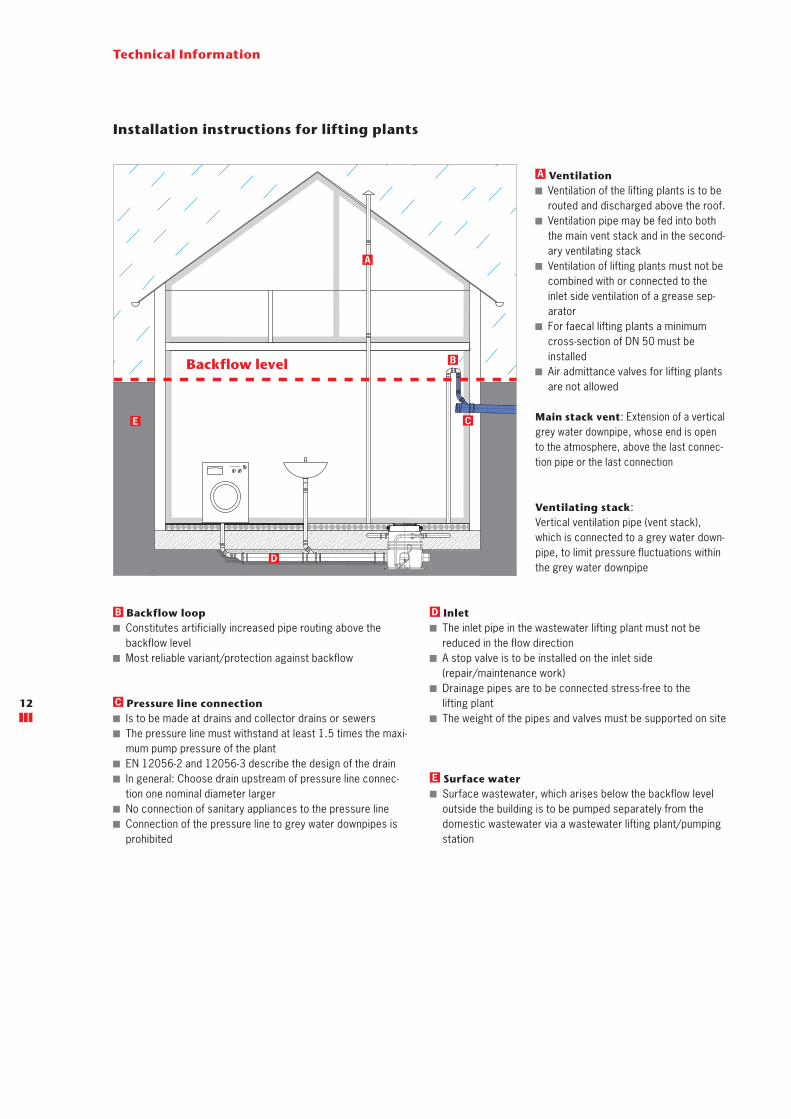
Installation instructions for lifting plants
Technical Information
Main stack vent: Extension of a vertical grey water downpipe, whose end is open to the atmosphere, above the last connec-tion pipe or the last connection
Ventilating stack: Vertical ventilation pipe (vent stack), which is connected to a grey water down-pipe, to limit pressure fluctuations within the grey water downpipe
Ventilation Ventilation of the lifting plants is to be routed and discharged above the roof.
Ventilation pipe may be fed into both the main vent stack and in the second-ary ventilating stack
Ventilation of lifting plants must not be combined with or connected to the inlet side ventilation of a grease sep-arator
For faecal lifting plants a minimum cross-section of DN 50 must be installed
Air admittance valves for lifting plants are not allowed
A
Backflow loop Constitutes artificially increased pipe routing above the backflow level
Most reliable variant/protection against backflow
B
Pressure line connection Is to be made at drains and collector drains or sewers The pressure line must withstand at least 1.5 times the maxi-mum pump pressure of the plant
EN 12056-2 and 12056-3 describe the design of the drain In general: Choose drain upstream of pressure line connec-tion one nominal diameter larger
No connection of sanitary appliances to the pressure line Connection of the pressure line to grey water downpipes is prohibited
C
Inlet The inlet pipe in the wastewater lifting plant must not be reduced in the flow direction
A stop valve is to be installed on the inlet side (repair/maintenance work)
Drainage pipes are to be connected stress-free to the lifting plant
The weight of the pipes and valves must be supported on site
D
Surface water Surface wastewater, which arises below the backflow level outside the building is to be pumped separately from the domestic wastewater via a wastewater lifting plant/pumping station
E
12

B
J
K
D
L
C
GF
H
E
A
Technical Information
Usable volume Pumpable volume between the switch-ing on and switching off level of the pump
Usable volume must be larger than the volume in the pressure line up to the backflow loop
Installation space Must be adequately ventilated to avoid condensation
Must be large enough to provide a working space of at least 60 cm width and height next to and above all parts to be operated and maintained
Adequate lighting must be available A pump sump is to be provided for drainage of the room
Muli Pro-PE N XL duo lifting plant Pump control CEE mains socket with earth contact Air bubble injection (optional) Backflow loop Ventilation line Pressure pipe Stop valve (optional) Chamber ventilation line Manual diaphragm pump (optional) Three-way valve (optional) Grease separator (optional)
Sampling pot (optional)
A
B
C
D
E
F
H
I
I
J
K
L
M
M
G
13
Buoyancy protection The plant must stand firmly on the floor and must be locked against rotation
To prevent floating up in case of flooding
To prevent damage to connections/pipes
Electrical installationThe electrical installation must be carried out by a qualified electrician. Switching devices and signalling units must be installed in a dry, easily acces-sible place where the signalling unit can be easily seen and heard.
Pump sump (on site) For draining the installation room Can be drained by a manual dia-phragm pump or automatically operat-ing drainage pump in the pressure line of the lifting plant downstream of the backflow loop

14
Was
tew
ater
lift
ing
pla
nts
Wastewater Lifting Plants –Product Overview
Apart from the installation site and delivery head, the quality of the wastewater is another important aspect for choosing the right lifting plant. Wastewater from washing machines or washbasins, so-called grey water (non-faecal wastewater), does not contain any bulky solids. It can therefore be transported more easily than black water (faecal wastewater), which is soiled with human faeces. Lifting plants for fae-cal wastewater are therefore designed to easily transport solids with-out blocking.
15

ACO Muli-Mini duo lifting plant non faecal wastewater – for freestanding installation
Product information
■ Areas of use � Downstream of grease separators up to NS 4 � Laundry rooms � Multiple shower installations
■ Tank made of polyethylene � Bottom outlet R 1" � Inspection opening for easy maintenance, diameter: 340 mm
� Connection for manual diaphragm pump DN 50 � 4 horizontal inlet sockets DN 100 � 1 vertical inlet socket DN 100 � Optional 1 vertical inlet socket DN 50 (accessory) � 1 ventilation socket DN 70
■ Delivery line connection � Special backflow valve with ball in the housing � Connection: Rp 2“
■ 2 submersible grey water pumps � With three-phase current submerged motor pump: 400 V, 50 Hz – type D
� With alternating current submersible pump: 230 V, 50 Hz – type W
� Degree of protection IP 68 � Double mechanical seal with oil chamber between the seals
� With blockage-free vortex impeller � 10 m connection cable
■ Level switching � Pneumatic level switching with 10 m control cables � Optionally with air bubble injection to increase operating reliability if installed downstream of a grease separator (accessory)
■ Control � Degree of protection IP 54 � 1.5 m cable and CEE plug (16 A) – type D � 1.5 m cable and plug with earthing contact (16 A) – type W � Isolated group alarm and operation signal
■ Tested to EN 12050-2
Type Motor rating Characteristic data Freepassage Usable volume Total
volume Weight Article No.
P1 P2
Currentcon-
sump-tion
Voltage SpeedInlet
heightZ1
Inlet height
Z2
Inletfrom above
[kW] [kW] [A] [V] [rpm] [mm] [l] [l] [l] [l] [kg]
Muli-Mini DDP 1.1 0.7 0.55 1.3 400 2900 38 55 100 130 195 66 1206.00.01
Muli-Mini DDP 1.2 1.5 1.1 2.6 400 2900 38 55 100 130 195 74 1206.00.02
Muli-Mini DWP 1.1 0.8 0.55 3.6 230 2900 38 55 100 130 195 66 1206.00.03
Muli-Mini DWP 1.2 1.8 1.1 8.2 230 2900 38 55 100 130 195 74 1206.00.04
Order information
Product advantages
■ Ready to connect ■ Different inlet heights selectable ■ High usable volume – up to 140 l ■ Toolless dismantling of the pump ■ Adapted to minimum door size: 700 mm ■ Low weight
Wastewater lifting plants
Suitable for:
■ Grey water ■ Use downstream of grease separators up to NS 4
16
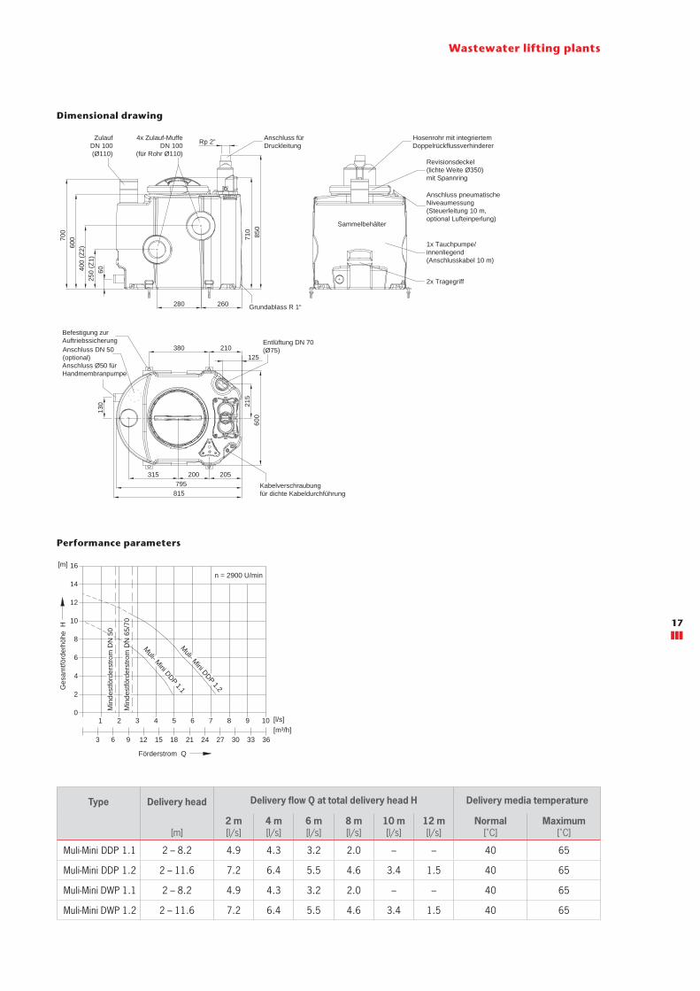
Dimensional drawing
Wastewater lifting plants
Performance parameters
Type Delivery head Delivery flow Q at total delivery head H Delivery media temperature
[m]2 m[l/s]
4 m[l/s]
6 m[l/s]
8 m[l/s]
10 m[l/s]
12 m[l/s]
Normal[˚C]
Maximum[˚C]
Muli-Mini DDP 1.1 2 – 8.2 4.9 4.3 3.2 2.0 – – 40 65
Muli-Mini DDP 1.2 2 – 11.6 7.2 6.4 5.5 4.6 3.4 1.5 40 65
Muli-Mini DWP 1.1 2 – 8.2 4.9 4.3 3.2 2.0 – – 40 65
Muli-Mini DWP 1.2 2 – 11.6 7.2 6.4 5.5 4.6 3.4 1.5 40 65
ZulaufDN 100(Ø110)
Hosenrohr mit integriertem Doppelrückflussverhinderer
Revisionsdeckel(lichte Weite Ø350)mit Spannring
1x Tauchpumpe/innenliegend(Anschlusskabel 10 m)
Sammelbehälter
Befestigung zurAuftriebssicherung
Anschluss Ø50 fürHandmembranpumpe
Grundablass R 1“
60400
(Z2)
700
250
(Z1)
600 85
071
0
125
260
Rp 2”
205795
200
600
815
215
Anschluss fürDruckleitung
Anschluss pneumatischeNiveaumessung(Steuerleitung 10 m,optional Lufteinperlung)
4x Zulauf-MuffeDN 100
(für Rohr Ø110)
315
210
280
380
130
Kabelverschraubungfür dichte Kabeldurchführung
Entlüftung DN 70(Ø75)
2x Tragegriff
Steuerung(steckerfertig)
Anschlusskabel 1,5 m undCEE-Stecker 16 A (Typ DDP)
Anschlusskabel 1,5 m undSchuko-Stecker (Typ DWP)
315 x 13028
5
Anschluss DN 50(optional)
Muli- Mini DDP 1.1
Min
dest
förd
erst
rom
DN
65/
70
Min
dest
förd
erst
rom
DN
50
Muli- Mini DDP 1.2
n = 2900 U/min
1512963 36333027242118
4321 10987650
2
4
6
8
10
12
14
16
Ges
amtfö
rder
höhe
H
[m]
[m³/h][l/s]
Förderstrom Q
17

ACO Muli-Star DDP wastewater lifting plantfor faecal wastewater – for freestanding installation
Product information
■ Areas of use � Downstream of grease separators up to NS 15 � Multiple dwelling units � Office buildings, hotels � hospitals, Areas of use
■ Tank made of polyethylene � Bottom outlet R 1" � Inspection opening for easy maintenance, diameter: 130 mm (DDP1), 130 mm and 250 mm (DDP2)
� Connection for manual diaphragm pump DN 50 � 2 horizontal inlet sockets DN 100 � 4 horizontal inlet sockets DN 150 � 2 vertical inlet sockets DN 100 / DN 150 / DN 200 � 1 ventilation socket DN 70 (optional DN 100)
■ Delivery line connection � Special backflow valve with ball in the housing � Special adapter DN 80 for elastic connection of the pressure line with 108 – 114.3 mm pipe outside diameter (optional 88 – 90 mm)
� Connecting flange for stop valve DN 80 PN 16 � 3-phase motor: 400 V, 50 Hz � Degree of protection IP 68 � Blockage-free free flow impeller � 10 m connection cable
■ Level switching � Pneumatic level switching with 10 m control cable � Optionally with air bubble injection (accessory)
■ Control � Degree of protection IP 54 � 1.5 m cable and CEE plug (32 A)
■ Isolated group alarm and operation signal ■ Tested to EN 12050-1
Type Motor rating Characteristic data Freepassage Usable volume Total
volume Weight Article No.
P1 P2
Currentcon-
sump-tion
Voltage SpeedInlet
heightZ1
Inlet height
Z2
Inletfrom above
[kW] [kW] [A] [V] [rpm] [mm] [l] [l] [l] [l] [kg]
Muli-Star DDP 1.1 1.83 1.5 5 400 1400 65 65 110 110 150 66 1202.00.01
Muli-Star DDP 1.2 3.45 3 10 400 2800 65 65 110 110 150 74 1202.00.02
Muli-Star DDP 2.1 1.83 1.5 5 400 1400 65 95 185 185 300 66 1202.00.04
Muli-Star DDP 2.2 3.45 3 10 400 2800 65 95 185 185 300 74 1202.00.05
Order information
Product advantages
■ Low weight ■ Different inlet heights ■ CFD-optimised impeller ■ Ready to connect ■ High usable volume – up to 185 l ■ Adapted to door dimension: 780 mm
Wastewater lifting plants
Suitable for:
■ Grey and black water ■ Use downstream of grease separators up to NS 15
18
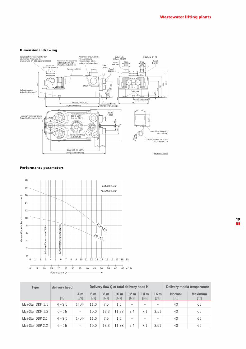
Wastewater lifting plants
Performance parameters
Type delivery head Delivery flow Q at total delivery head H Delivery media temperature
[m]4 m[l/s]
6 m[l/s]
8 m[l/s]
10 m[l/s]
12 m[l/s]
14 m[l/s]
16 m[l/s]
Normal[˚C]
Maximum[˚C]
Muli-Star DDP 1.1 4 – 9.5 14.44 11.0 7.5 1.5 – – – 40 65
Muli-Star DDP 1.2 6 – 16 – 15.0 13.3 11.38 9.4 7.1 3.51 40 65
Muli-Star DDP 2.1 4 – 9.5 14.44 11.0 7.5 1.5 – – – 40 65
Muli-Star DDP 2.2 6 – 16 – 15.0 13.3 11.38 9.4 7.1 3.51 40 65
Dimensional drawing
Griffmulde
280 x 120
310
Revisionsschraub-deckel Ø130
Anschluss pneumatischeNiveaumessung(Steuerleitung 10 m,optional Lufteinperlung)
ZulaufDN 100
ZulaufDN 200
Zulauf oderLüftung DN 100
ZulaufDN 150
Spezialbefestigungsstück für denelastischen Anschluss derDruckleitung DN 100 (optional DN 80)
625
Ø108-114,3(optional Ø88-90)
150
1200 (800 bei DDP1)
115
770
125
210
1550 (1150 bei DDP1)
160
Ø110Ø160
Ø160
50
520
690
400
620
740
Ø75Ø160
Ø110Ø200
40
400
(Z2)
250
(Z1)
980 (580 bei DDP1)1320 (920 bei DDP1)
ZulaufDN 150
Hosenrohr mit integriertemDoppelrückflussverhinderer
Grundablass R 1
Befestigung zurAuftriebssicherung
Revisionsschraub-deckel Ø250 (nur bei DDP2)
Freistrom-Kreiselpumpemit Drehstrommotor(Anschlusskabel 10 m)
Entlüftung DN 70
Sammelbehälter
zugehörige Steuerung(steckerfertig)
Anschlusskabel 1,5 m und
dargestellt: DDP2
CEE-Stecker 32 A
Anschluss Ø 50 fürHandmembranpumpe
m
Ges
amtfö
rder
höhe
H
Toleranzen ISO 2548/C
0
l/s0
m /h3
10
4
2
01 2 3 4 5 6 7 8 9 10 11 12 13 14 15 16 17 18
5 10 15 20 25 30 35 40 45 50 55 60 65
n=1450 1/min
*n=2900 1/min
Min
dest
förd
erst
rom
DN
80
Min
dest
förd
erst
rom
DN
1008
6
18
12
14
16
20
DDP x.1
*
Förderstrom Q
DDP x.2
19

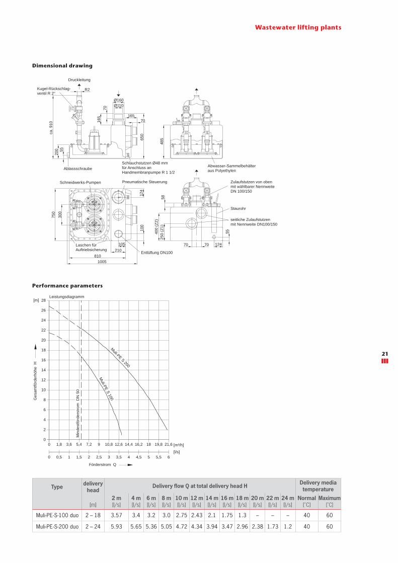
ACO Muli-PE-S duo wastewater lifting plantfor faecal wastewater – for freestanding installation
Product information
■ Areas of use � Renovation of old buildings � Where long pressure line to the sewer � Properties in which liquids with solid or fibrous substances occur, e.g. laundries
■ Tank made of polyethylene � With drain plug � With connection for manual diaphragm pump R 1½" � With 2 horizontal inlet sockets DN 100 / DN 150 � With 1 vertical inlet socket with step DN 100 / DN 150 � With ventilation socket DN 100
■ Delivery line connection � With 2 ball backflow stops R 2" � With 2 stop valves R 2" � Y-branch pipe R 2", made of stainless steel
Type Motor rating Characteristic data Usable volume Total volume Weight Article No.
P1 P2Current
consump-tion
Voltage SpeedInlet
heightZ1
Inlet height
Z2
Inletfrom above
[kW] [kW] [A] [V] [rpm] [l] [l] [l] [l] [kg]
Muli-PE-S-100 duo 1.2 0.9 2.3 400 2900 40 60 60 105 180 0159.04.24
Muli-PE-S-200 duo 2.5 1.7 4.1 400 2900 40 60 60 105 185 0175.02.67
Order information
Product advantages
■ Wastewater lifting plant with submersible pump and grinder
■ Different inlet heights ■ Lower costs due to small pressure line cross-section
Wastewater lifting plants
■ 2 pump units � Motor 400 V, 50 Hz � Degree of protection IP 68
■ Pneumatic level switching with pneumatic pipe and pneumatic control line
■ Switching and warning device � Degree of protection IP 54 � With 1.5 m cable and CEE plug � With isolated group alarm and operation signal � Incl. 4 m pneumatic control line between lifting plant and switchbox
■ Tested to EN 12050-1
Suitable for:
■ Grey and black water ■ Not for use downstream of grease separators
20
Wastewater lifting plants
Performance parameters
Type delivery head
Delivery flow Q at total delivery head H Delivery media temperature
[m]2 m[l/s]
4 m[l/s]
6 m[l/s]
8 m[l/s]
10 m[l/s]
12 m[l/s]
14 m[l/s]
16 m[l/s]
18 m[l/s]
20 m[l/s]
22 m[l/s]
24 m[l/s]
Normal[˚C]
Maximum[˚C]
Muli-PE-S-100 duo 2 – 18 3.57 3.4 3.2 3.0 2.75 2.43 2.1 1.75 1.3 – – – 40 60
Muli-PE-S-200 duo 2 – 24 5.93 5.65 5.36 5.05 4.72 4.34 3.94 3.47 2.96 2.38 1.73 1.2 40 60
Dimensional drawing
Min
dest
förd
erst
rom
DN
50
1814,4 21,619,816,2
3,5 5,54,54 65[l/s]
[m³/h]0
8
6
4
2
0
0
22
20
18
16
14
12
10
0,5 1 1,5 2,52 3
1,8 3,6 5,4 7,2 9 10,8 12,6
Leistungsdiagramm Toleranzen ISO 2548/C
26
24
28[m]M
uli-PE S 100Muli-PE S 200
Förderstrom Q
Ges
amtfö
rder
höhe
H
Zulaufstutzen von obenmit wählbarer NennweiteDN 100/150
AnschlusspneumatischeSteuerleitung(4 m lang)
Schaltgerät steckerfertig(250 x 195 x 100)
AnschlussSammelstörmeldung
Motorkabel(4 m lang)
AnschlussKleinstkompressor
Anschlusskabel1,5 m lang mitCEKON-Stecker 16 A
Entlüftung DN100
seitliche Zulaufstutzen mit Nennweite DN100/150
Staurohr
Schlauchstutzen Ø48 mmfür Anschluss anHandmembranpumpe R 1 1/2
Pneumatische Steuerung
Abwasser-Sammelbehälteraus Polyethylen
5520
0ca
. 910
105210
1005
Laschen fürAuftriebsicherung
810
100
124
300
750
250
(Z1)
400
(Z2)
5848
5
55
7070 124
R2
Ablassschraube
Schneidwerks-Pumpen
Druckleitung
Ø110Ø160
7016
5
70165
650
Kugel-Rückschlag-ventil R 2"
21

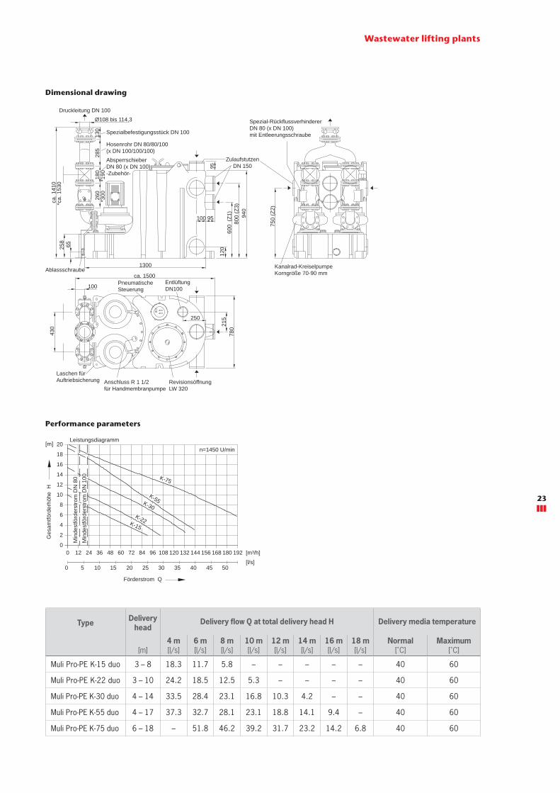
ACO Muli Pro-PE K duo wastewater lifting plantfor faecal wastewater – for freestanding installation
Product information
■ Areas of use � Multiple dwelling units � Smaller commercial properties with large quantities of wastewater
� Downstream of grease separators up to NS 20 � For long pressure line sections with large level differences
■ Tank made of polyethylene � With drain plug � With connection for manual diaphragm pump R 1½" � With 4 horizontal inlet sockets DN 150 � With 1 vertical inlet socket DN 150 � With 1 inspection opening, clear width: 320 mm � With ventilation socket DN 100
■ Delivery line connection � With 2 special backflow valves DN 80 (DN 100 for Muli Pro-PE K-75 duo) with backwash device
� With Y-branch pipe � With special adapter DN 100 for connection of the pressure line with 108 – 114.3 mm pipe outside diameter
■ 2 pump units � Motor 400 V, 50 Hz � Degree of protection IP 68 � With channel impeller
■ Pneumatic level switching with pneumatic pipe and pneumat-ic control line
■ Incl. mini compressor for air bubble injection ■ Switching and warning device
� Degree of protection IP 54 � With 1.5 m cable and CEE plug � With isolated group alarm and operation signal � Incl. 7 m cable between lifting plant and switchbox
■ Tested to EN 12050-1 ■ K-55/K-75: control box with smooth start & stop
Type Motorcapacity
Characteristic data Freepassage Usable volume Total
volume Weight Article No.
P1 P2
Currentcon-
sump-tion
Voltage SpeedInlet
heightZ1
Inlet height
Z2
Inlet height
Z3
Inlet from above
[kW] [kW] [A] [V] [rpm] [mm] [l] [l] [l] [l] [l] [kg]
Muli Pro-PE K-15 duo 2.01 1.5 3.6 400 1450 70 240 305 330 330 520 295 0175.13.17
Muli Pro-PE K-22 duo 2.94 2.2 5.2 400 1450 70 240 305 330 330 520 310 0175.13.18
Muli Pro-PE K-30 duo 3.87 3 6.6 400 1450 70 240 305 330 330 520 350 0175.13.19
Muli Pro-PE K-55 duo 6.71 5.5 11.6 400 1450 70 240 305 330 330 520 425 0175.13.20
Muli Pro-PE K-75 duo 8.97 7.5 15.5 400 1450 100 240 305 330 330 520 495 0175.13.21
Order information
Product advantages
■ Large usable tank volume ■ Different inlet heights ■ High operational safety due to pneumatic pipe and air bubble injection
■ Suitable for greasy wastewater ■ Energy saving channel impeller pump ■ Adapted to door dimension: 780 mm
Wastewater lifting plants
Suitable for:
■ Grey and black water ■ Use downstream of grease separators up to NS 20
22
Wastewater lifting plants
Performance parameters
Type Delivery head
Delivery flow Q at total delivery head H Delivery media temperature
[m]4 m[l/s]
6 m[l/s]
8 m[l/s]
10 m[l/s]
12 m[l/s]
14 m[l/s]
16 m[l/s]
18 m[l/s]
Normal[˚C]
Maximum[˚C]
Muli Pro-PE K-15 duo 3 – 8 18.3 11.7 5.8 – – – – – 40 60
Muli Pro-PE K-22 duo 3 – 10 24.2 18.5 12.5 5.3 – – – – 40 60
Muli Pro-PE K-30 duo 4 – 14 33.5 28.4 23.1 16.8 10.3 4.2 – – 40 60
Muli Pro-PE K-55 duo 4 – 17 37.3 32.7 28.1 23.1 18.8 14.1 9.4 – 40 60
Muli Pro-PE K-75 duo 6 – 18 – 51.8 46.2 39.2 31.7 23.2 14.2 6.8 40 60
Dimensional drawing
*ca.
153
0
Schaltgerät steckerfertig( 250 x 195 x 100 )
Anschlusskabel1,5 m lang mitCEKON-Stecker 16 A
Anschluss pneum. Steuerleitung
Motorkabel(4 m lang)
AnschlussKleinstkompressor
Anschluss fürpotenzialfreieSammelstörmeldungund Betriebsmeldung
Anschluss für Notstromversorgung
Kleinstkompressorfür Lufteinperlung
65258
ca. 1
410
*300260
180
*190
285
130
Ø108 bis 114,3
9510012
060
0 (Z
1)80
0 (Z
3)94
0
95
130075
0 (Z
2)
430
ca. 1500
100
215
780
250
Spezial-Rückflussverhinderer DN 80 (x DN 100)mit Entleerungsschraube
Entlüftung DN100
Ablassschraube
Laschen fürAuftriebsicherung
PneumatischeSteuerung
Spezialbefestigungsstück DN 100
AbsperrschieberDN 80 (x DN 100)-Zubehör-
Kanalrad-KreiselpumpeKorngröße 70-90 mm
Anschluss R 1 1/2für Handmembranpumpe
RevisionsöffnungLW 320
Druckleitung DN 100
Hosenrohr DN 80/80/100(x DN 100/100/100)
ZulaufstutzenDN 150
Anschluss pneum. Steuerleitung"ALARM 1"
Min
dest
förd
erst
rom
DN
80
Leistungsdiagramm Toleranzen ISO 2548/C
n=1450 U/min
Min
dest
förd
erst
rom
DN
100
20
18
16
14
12
10
8
6
4
2
00
0 5 10 15 20 25 30 35 40 45 50
12 24 36 48 60 72 84 96 108 120 132 144 156 168 180 192
K-75
K-55K-30K-22K-15
Ges
amtfö
rder
höhe
H
[m]
[m³/h]
[l/s]
Förderstrom Q
23
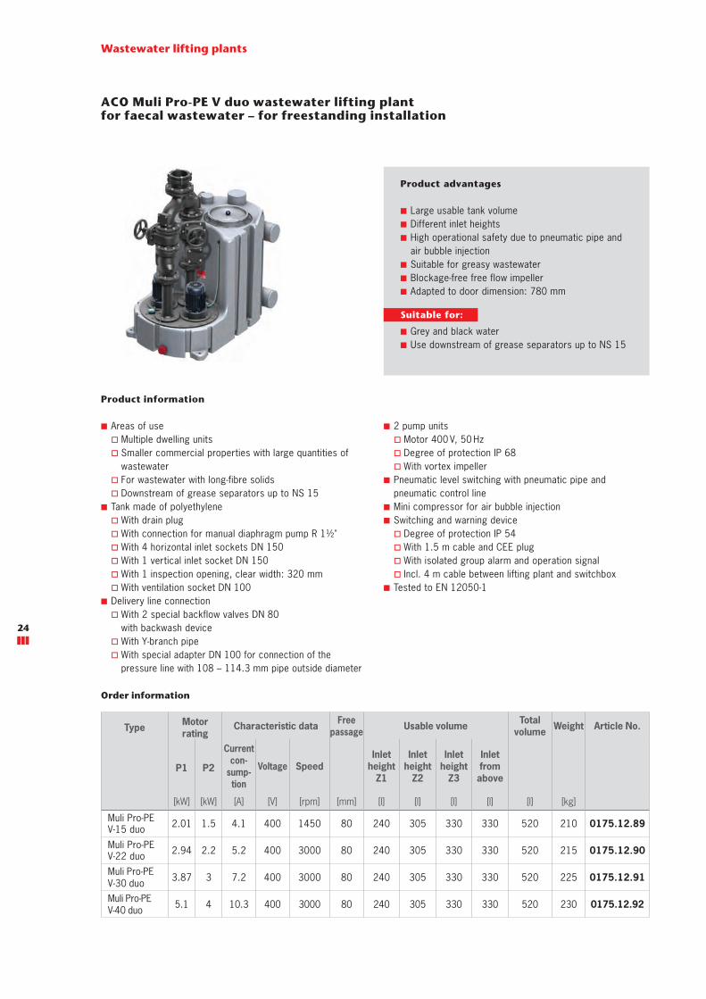
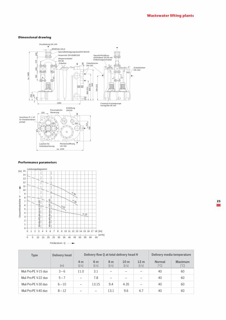
ACO Muli Pro-PE V duo wastewater lifting plantfor faecal wastewater – for freestanding installation
Product information
■ Areas of use � Multiple dwelling units � Smaller commercial properties with large quantities of wastewater
� For wastewater with long-fibre solids � Downstream of grease separators up to NS 15
■ Tank made of polyethylene � With drain plug � With connection for manual diaphragm pump R 1½" � With 4 horizontal inlet sockets DN 150 � With 1 vertical inlet socket DN 150 � With 1 inspection opening, clear width: 320 mm � With ventilation socket DN 100
■ Delivery line connection � With 2 special backflow valves DN 80 with backwash device
� With Y-branch pipe � With special adapter DN 100 for connection of the pressure line with 108 – 114.3 mm pipe outside diameter
■ 2 pump units � Motor 400 V, 50 Hz � Degree of protection IP 68 � With vortex impeller
■ Pneumatic level switching with pneumatic pipe and pneumatic control line
■ Mini compressor for air bubble injection ■ Switching and warning device
� Degree of protection IP 54 � With 1.5 m cable and CEE plug � With isolated group alarm and operation signal � Incl. 4 m cable between lifting plant and switchbox
■ Tested to EN 12050-1
Type Motor rating
Characteristic data Freepassage Usable volume Total
volume Weight Article No.
P1 P2
Currentcon-
sump-tion
Voltage SpeedInlet
heightZ1
Inlet height
Z2
Inlet height
Z3
Inletfrom above
[kW] [kW] [A] [V] [rpm] [mm] [l] [l] [l] [l] [l] [kg]
Muli Pro-PE V-15 duo 2.01 1.5 4.1 400 1450 80 240 305 330 330 520 210 0175.12.89
Muli Pro-PE V-22 duo 2.94 2.2 5.2 400 3000 80 240 305 330 330 520 215 0175.12.90
Muli Pro-PE V-30 duo 3.87 3 7.2 400 3000 80 240 305 330 330 520 225 0175.12.91
Muli Pro-PE V-40 duo 5.1 4 10.3 400 3000 80 240 305 330 330 520 230 0175.12.92
Order information
Product advantages
■ Large usable tank volume ■ Different inlet heights ■ High operational safety due to pneumatic pipe and air bubble injection
■ Suitable for greasy wastewater ■ Blockage-free free flow impeller ■ Adapted to door dimension: 780 mm
Wastewater lifting plants
Suitable for:
■ Grey and black water ■ Use downstream of grease separators up to NS 15
24
Wastewater lifting plants
Performance parameters
Type Delivery head Delivery flow Q at total delivery head H Delivery media temperature
[m]4 m[l/s]
6 m[l/s]
8 m[l/s]
10 m[l/s]
12 m[l/s]
Normal[˚C]
Maximum[˚C]
Muli Pro-PE V-15 duo 3 – 6 11.0 3.1 – – – 40 60
Muli Pro-PE V-22 duo 5 – 7 – 7.8 – – – 40 60
Muli Pro-PE V-30 duo 6 – 10 – 13.15 9.4 4.35 – 40 60
Muli Pro-PE V-40 duo 8 – 12 – – 13.1 9.6 4.7 40 60
Dimensional drawing
Schaltgerät steckerfertig(250 x 195 x 100)
Anschlusskabel1,5 m lang mitCEKON-Stecker 16 A
Anschluss pneum. Steuerleitung
Motorkabel(4 m lang)
AnschlussKleinstkompressor
Anschluss pneum. Steuerleitung"ALARM 1"
Anschluss fürpotentialfreieSammelstörmeldungund Betriebsmeldung
Anschluss für Notstromversorgung
Kleinstkompressorfür Lufteinperlung
Druckleitung DN 100
SpezialbefestigungsstückDN 80/100
Absperrschieber DN 80 -Zubehör-
Ø108 bis 114,3
260
Hosenrohr DN 80/80/100
180
270
160
Freistrom-KreiselpumpeKorngröße 80 mm
65258
ca. 1
480
120
600
(Z1)
800
(Z3) 940
95
95
100
ZulaufstutzenDN 150
Spezial-Rückfluss-verhinderer DN 80 mit Entleerungsschraube
1300
750
(Z2)
ZulaufstutzenDN 150
PneumatischeSteuerung
EntlüftungDN100
Laschen fürAuftriebsicherung
RevisionsöffnungLW 320
ca. 1440
215250
780
325
Anschluss R 1 1/2für Handmembran-pumpe
Leistungsdiagramm Toleranzen ISO 2548/C15
14
13
12
11
10
9
8
7
6
5
4
3
2
1
00 1 2 3 4 5 6 7 8 9 10 11 12 13 14 15 16 17 18
0 5 10 15 20 25 30 35 40 45 50 55 60 65
Min
dest
förd
erst
rom
DN
80
Min
dest
förd
erst
rom
DN
100
V-40
V-30V-22
V-15
Ges
amtfö
rder
höhe
H
[m]
[m³/h][l/s]
Förderstrom Q
25

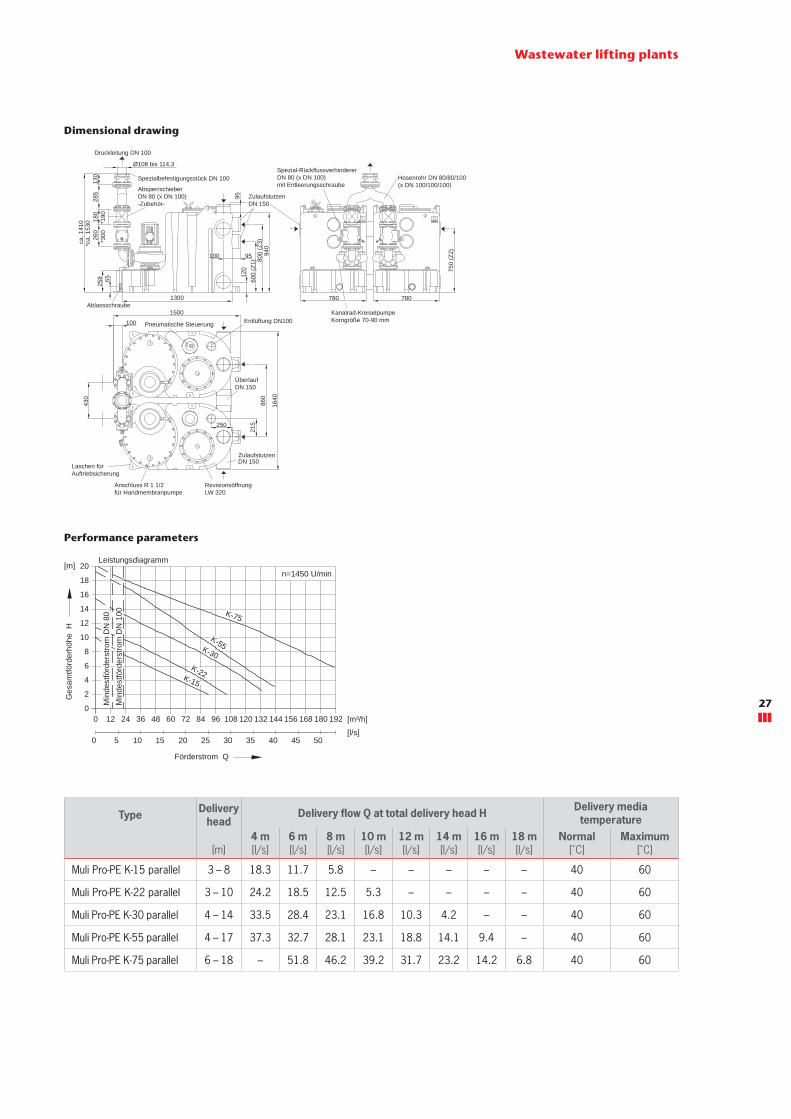
ACO Muli Pro-PE K Parallel wastewater lifting plantfor faecal wastewater – for freestanding installation
Product information
■ Areas of use � Commercial or industrial properties with large quantities of wastewater
� For long pressure line sections with large level differences ■ Tank made of polyethylene
� With drain plug � With connection for manual diaphragm pump R 1½" � With 6 horizontal inlet sockets DN 150 � With 2 vertical inlet socket DN 150 � With 2 inspection openings, clear width: 320 mm � With ventilation socket DN 100
■ Delivery line connection � With 2 special backflow valves DN 80 (DN 100for Muli Pro-PE K-75 Parallel) with backwash device
� With Y-branch pipe � With special adapter DN 100 for connection of the pres-sure line with 108 – 114.3 mm pipe outside diameter
■ 2 pump units � Motor 400 V, 50 Hz � Degree of protection IP 68 � With channel impeller
■ Pneumatic level switching with pneumatic pipe and pneumatic control line
■ Mini compressor for air bubble injection ■ Switching and warning device
� Degree of protection IP 54 � With 1.5 m cable and CEE plug � With isolated group alarm and operation signal � Incl. 7 m cable between lifting plant and switchbox
■ Tested to EN 12050-1 ■ K-55/K-75: control box with smooth start & stop
Type Motorrating
Characteristic data Freepassage Usable volume Total
volume Weight Article No.
P1 P2
Currentcon-
sump-tion
Voltage SpeedInlet
heightZ1
Inlet height
Z2
Inlet height
Z3
Inletfromabove
[kW] [kW] [A] [V] [rpm] [mm] [l] [l] [l] [l] [l] [kg]
Muli Pro-PE K-15 parallel 2.01 1.5 3.6 400 1450 70 480 610 660 660 1040 315 0175.13.23
Muli Pro-PE K-22 parallel 2.94 2.2 5.2 400 1450 70 480 610 660 660 1040 325 0175.13.24
Muli Pro-PE K-30 parallel 3.87 3 6.6 400 1450 70 480 610 660 660 1040 420 0175.13.25
Muli Pro-PE K-55 parallel 6.71 5.5 11.6 400 1450 70 480 610 660 660 1040 465 0175.13.26
Muli Pro-PE K-75 parallel 8.97 7.5 15.5 400 1450 70 480 610 660 660 1040 510 0175.13.27
Order information
Product advantages
■ Large usable tank volume ■ Different inlet heights ■ High operational safety due to pneumatic pipe andair bubble injection
■ Energy saving channel impeller pump ■ Adapted to door dimension: 780 mm ■ Can be brought in separately
Wastewater lifting plants
Suitable for:
■ Grey and black water ■ Use downstream of grease separators up to NS 20
26
Wastewater lifting plants
Performance parameters
Type Delivery head
Delivery flow Q at total delivery head H Delivery media temperature
[m]4 m[l/s]
6 m[l/s]
8 m[l/s]
10 m[l/s]
12 m[l/s]
14 m[l/s]
16 m[l/s]
18 m[l/s]
Normal[˚C]
Maximum[˚C]
Muli Pro-PE K-15 parallel 3 – 8 18.3 11.7 5.8 – – – – – 40 60
Muli Pro-PE K-22 parallel 3 – 10 24.2 18.5 12.5 5.3 – – – – 40 60
Muli Pro-PE K-30 parallel 4 – 14 33.5 28.4 23.1 16.8 10.3 4.2 – – 40 60
Muli Pro-PE K-55 parallel 4 – 17 37.3 32.7 28.1 23.1 18.8 14.1 9.4 – 40 60
Muli Pro-PE K-75 parallel 6 – 18 – 51.8 46.2 39.2 31.7 23.2 14.2 6.8 40 60
Dimensional drawing
*ca.
153
0
Schaltgerät steckerfertig(250 x 195 x 100) Anschlusskabel
1,5 m lang mitCEKON-Stecker 16 A
Anschluss pneum. Steuerleitung
Motorkabel(4 m lang ) Anschluss
Kleinstkompressor
Anschluss pneum. Steuerleitung"ALARM 1"
Anschluss fürpotentialfreieSammelstörmeldungund Betriebsmeldung
Anschluss für Notstromversorgung
Kleinstkompressorfür Lufteinperlung
Spezial-RückflussverhindererDN 80 (x DN 100)mit Entleerungsschraube
Kanalrad-KreiselpumpeKorngröße 70-90 mm Entlüftung DN100
Ablassschraube
Laschen fürAuftriebsicherung
Pneumatische Steuerung
Spezialbefestigungsstück DN 100
AbsperrschieberDN 80 (x DN 100)-Zubehör-
Anschluss R 1 1/2für Handmembranpumpe
RevisionsöffnungLW 320
Druckleitung DN 100
Hosenrohr DN 80/80/100(x DN 100/100/100)
ZulaufstutzenDN 150
ÜberlaufDN 150
*300
*190
Ø108 bis 114,3
6525
8
ca. 1
410
1300
430
100
1500
860
1640
215
95100
9512
060
0 (Z
1) 800
(Z3)
940
780 780
750
(Z2)
ZulaufstutzenDN 150
260
180
285
130
250
Min
dest
förd
erst
rom
DN
80
Leistungsdiagramm Toleranzen ISO 2548/C
n=1450 U/min
Min
dest
förd
erst
rom
DN
100
20
18
16
14
12
10
8
6
4
2
00
0 5 10 15 20 25 30 35 40 45 50
12 24 36 48 60 72 84 96 108 120 132 144 156 168 180 192
K-75
K-55K-30K-22K-15
Ges
amtfö
rder
höhe
H
[m]
[m³/h]
[l/s]
Förderstrom Q
27
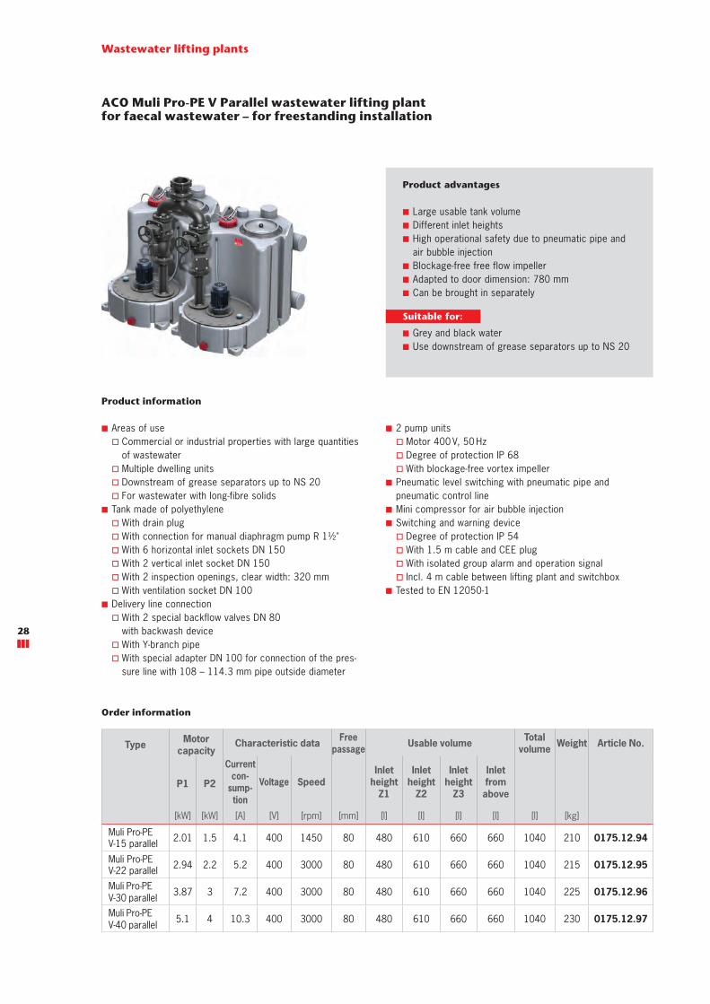
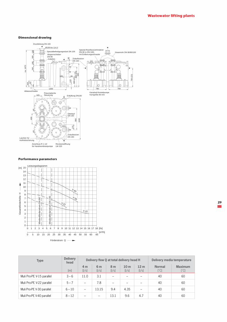
ACO Muli Pro-PE V Parallel wastewater lifting plantfor faecal wastewater – for freestanding installation
Product information
■ Areas of use � Commercial or industrial properties with large quantities of wastewater
� Multiple dwelling units � Downstream of grease separators up to NS 20 � For wastewater with long-fibre solids
■ Tank made of polyethylene � With drain plug � With connection for manual diaphragm pump R 1½" � With 6 horizontal inlet sockets DN 150 � With 2 vertical inlet socket DN 150 � With 2 inspection openings, clear width: 320 mm � With ventilation socket DN 100
■ Delivery line connection � With 2 special backflow valves DN 80 with backwash device
� With Y-branch pipe � With special adapter DN 100 for connection of the pres-sure line with 108 – 114.3 mm pipe outside diameter
■ 2 pump units � Motor 400 V, 50 Hz � Degree of protection IP 68 � With blockage-free vortex impeller
■ Pneumatic level switching with pneumatic pipe and pneumatic control line
■ Mini compressor for air bubble injection ■ Switching and warning device
� Degree of protection IP 54 � With 1.5 m cable and CEE plug � With isolated group alarm and operation signal � Incl. 4 m cable between lifting plant and switchbox
■ Tested to EN 12050-1
Product advantages
■ Large usable tank volume ■ Different inlet heights ■ High operational safety due to pneumatic pipe and air bubble injection
■ Blockage-free free flow impeller ■ Adapted to door dimension: 780 mm ■ Can be brought in separately
Wastewater lifting plants
Type Motorcapacity
Characteristic data Freepassage Usable volume Total
volume Weight Article No.
P1 P2
Currentcon-
sump-tion
Voltage SpeedInlet
heightZ1
Inlet height
Z2
Inlet height
Z3
Inletfromabove
[kW] [kW] [A] [V] [rpm] [mm] [l] [l] [l] [l] [l] [kg]
Muli Pro-PE V-15 parallel 2.01 1.5 4.1 400 1450 80 480 610 660 660 1040 210 0175.12.94
Muli Pro-PE V-22 parallel 2.94 2.2 5.2 400 3000 80 480 610 660 660 1040 215 0175.12.95
Muli Pro-PE V-30 parallel 3.87 3 7.2 400 3000 80 480 610 660 660 1040 225 0175.12.96
Muli Pro-PE V-40 parallel 5.1 4 10.3 400 3000 80 480 610 660 660 1040 230 0175.12.97
Order information
Suitable for:
■ Grey and black water ■ Use downstream of grease separators up to NS 20
28
Wastewater lifting plants
Performance parameters
Type Delivery head
Delivery flow Q at total delivery head H Delivery media temperature
[m]4 m[l/s]
6 m[l/s]
8 m[l/s]
10 m[l/s]
12 m[l/s]
Normal[˚C]
Maximum[˚C]
Muli Pro-PE V-15 parallel 3 – 6 11.0 3.1 – – – 40 60
Muli Pro-PE V-22 parallel 5 – 7 – 7.8 – – – 40 60
Muli Pro-PE V-30 parallel 6 – 10 – 13.15 9.4 4.35 – 40 60
Muli Pro-PE V-40 parallel 8 – 12 – – 13.1 9.6 4.7 40 60
Dimensional drawing
Schaltgerät steckerfertig(250 x 195 x 100)
Anschlusskabel1,5 m lang mitCEKON-Stecker 16 A
Anschluss pneum. Steuerleitung
Motorkabel(4 m lang)
AnschlussKleinstkompressor
Anschluss pneum. Steuerleitung"ALARM 1"
Anschluss fürpotentialfreieSammelstörmeldungund Betriebsmeldung
Anschluss für Notstromversorgung
Kleinstkompressorfür Lufteinperlung
6525
8ca
. 147
0
260
180
285
130
1300Ablassschraube
Kanalrad-KreiselpumpeKorngröße 80 mm
780 780
Spezialbefestigungsstück DN 100AbsperrschieberDN 80-Zubehör-
Hosenrohr DN 80/80/100 Spezial-Rückflussverhinderer DN 80 (x DN 100)mit Entleerungsschraube
750
(Z2)
120
600
(Z1) 80
0 (Z
3)94
095100
95 ZulaufstutzenDN 150
Druckleitung DN 100
Ø108 bis 114,3
PneumatischeSteuerung Entlüftung DN100
ÜberlaufDN 150
ZulaufstutzenDN 150Laschen für
Auftriebsicherung
Anschluss R 1 1/2für Handmembranpumpe
RevisionsöffnungLW 320
430
860
1640
250
215
325
Leistungsdiagramm Toleranzen ISO 2548/C15
14
13
12
11
10
9
8
7
6
5
4
3
2
1
00 1 2 3 4 5 6 7 8 9 10 11 12 13 14 15 16 17 18
0 5 10 15 20 25 30 35 40 45 50 55 60 65
Min
dest
förd
erst
rom
DN
80
Min
dest
förd
erst
rom
DN
100
V-40
V-30V-22
V-15
Ges
amtfö
rder
höhe
H
[m]
[m³/h][l/s]
Förderstrom Q
29

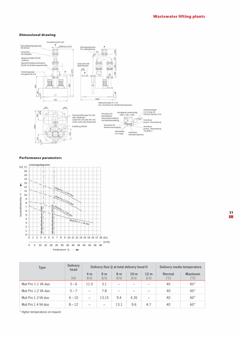
ACO Muli Pro 1.x VA duo wastewater lifting plantfor faecal wastewater – for freestanding installation
Product information
■ Areas of use � Multiple dwelling units � Smaller commercial properties with large quantities of wastewater
� Wastewater with long-fibre solids � Downstream of grease separators up to NS 10
■ Tank made of stainless steel, material 1.4571 AISI 314 � With drain plug � With connection for manual diaphragm pump R 1½" � Optional inspection opening or inlet socket � With 2 inspection openings, diameter: 285 mm or with horizontal inlet socket DN 100 / DN 150
� With ventilation connection DN 100 for connection to plastic pipe
■ Delivery line connection � Via 2 special backflow valves DN 80 with backwash device � With Y-branch pipe � With special integrated adapter DN 100 for connection of the delivery line with 108 – 114.3 mm pipe outside diameter
■ 2 pump units � Motor 400 V, 50 Hz � Degree of protection IP 68 � With vortex impeller
■ Pneumatic level switching with pneumatic pipe and pneumatic control line
■ Mini compressor for air bubble injection ■ Switching and warning device
� Degree of protection IP 54 � With 1.5 m cable and CEE plug � With isolated group alarm and operation signal � Incl. 4 m cable between lifting plant and switchbox
■ Tested to EN 12050-1
Product advantages
■ Suitable for greasy wastewater ■ High operational safety due to pneumatic pipe and air bubble injection
■ Blockage-free free flow impeller
Wastewater lifting plants
Order information
Type Motor rating Characteristic data Freepassage
Usablevolume
Total volume Weight Article No.
P1 P2Current
consump-tion
VoltageInletfromabove
[kW] [kW] [A] [V] [mm] [l] [l] [kg]
Muli Pro 1.1VA duo 2.01 1.5 4.1 400 80 155 270 210 0175.06.69
Muli Pro 1.2 VA duo 2.94 2.2 5.2 400 80 155 270 215 0175.06.70
Muli Pro 1.3 VA duo 3.87 3 7.2 400 80 155 270 225 0175.06.71
Muli Pro 1.4 VA duo 5.1 4 10.3 400 80 155 270 230 0175.06.72
Suitable for:
■ Grey and black water ■ Use downstream of grease separators up to NS 10
30
Wastewater lifting plants
Performance parameters
* Higher temperatures on request
Type Delivery head
Delivery flow Q at total delivery head H Delivery media temperature
[m]4 m[l/s]
6 m[l/s]
8 m[l/s]
10 m[l/s]
12 m[l/s]
Normal[˚C]
Maximum[˚C]
Muli Pro 1.1 VA duo 3 – 6 11.0 3.1 – – – 40 60*
Muli Pro 1.2 VA duo 5 – 7 – 7.8 – – – 40 60*
Muli Pro 1.3 VA duo 6 – 10 – 13.15 9.4 4.35 – 40 60*
Muli Pro 1.4 VA duo 8 – 12 – – 13.1 9.6 4.7 40 60*
Dimensional drawing
Schaltgerät steckerfertig(250 x 195 x 100)
Anschlusskabel1,5 m lang mitCEKON-Stecker 16 A
Anschluss pneum. Steuerleitung
Motorkabel(4 m lang) Anschluss
Kleinstkompressor
Anschluss pneum. Steuerleitung"ALARM 1"
Anschluss fürpotentialfreieSammelstörmeldungund Betriebsmeldung
Anschluss für Notstromversorgung
Kleinstkompressorfür Lufteinperlung
SpezialbefestigungsstückDN 80/100
HosenrohrDN 80/80/80
Spezial-RückflussverhindererDN 80 mit Entleerungsschraube
Absperrschieber DN 80 -Zubehör-
Druckleitung DN 100
Ø108 bis 114,3
FreistrompumpeKorngröße 80 mm
1026
563
8 688
ca. 1
475
750
Revisionsöffnungen Rd 185oder wahlweiseZulauf DN 100 oder DN 150rechts, links oder beiderseits
Entlüftung DN100
300 12
5
1000
275
10
333
160 160
Zulauf DN 100Spannflansch
Ablassschraube R 1 1/2bzw. Anschluss für Handmembranpumpe
1000
48
125
260
180
270
160
Leistungsdiagramm Toleranzen ISO 2548/C17161514131211109876543210
0 1 2 3 4 5 6 7 8 9 10 11 12 13 14 15 16 17 18
0 5 10 15 20 25 30 35 40 45 50 55 60 65
Min
dest
förd
erst
rom
DN
80
Min
dest
förd
erst
rom
DN
100
[m]
[l/s]
[m³/h]
Förderstrom Q
Ges
amtfö
rder
höhe
H Muli-Pro 1.3 VA duo
Muli-Pro 1.4 VA duo
Muli-Pro 1.2 VA duo
Muli-Pro 1.1 VA duo
31

ACO Muli Pro 2.x VA duo wastewater lifting plantfor faecal wastewater – for freestanding installation
Product information
■ Areas of use � Multiple dwelling units � Downstream of grease separators up to NS 10 � For municipal and industrial wastewater
■ Tank made of stainless steel, material 1.4571 � With drain plug � With connection for manual diaphragm pump R 1½" � Optional inspection opening or inlet socket � With 2 inspection openings, diameter: 285 mm or with horizontal inlet socket DN 100 / DN 150
� With ventilation connection DN 100 for connection to plastic pipe
■ Delivery line connection � Via 2 special backflow valves DN 80 with backwash device � With special integrated adapter DN 100 for connection of the delivery line with 108 – 114.3 mm pipe outside diameter
■ 2 pump units � Motor 400 V, 50 Hz � Degree of protection IP 68 � With vortex impeller
■ Pneumatic level switching with pneumatic pipe and pneumatic control line
■ Mini compressor for air bubble injection ■ Switching and warning device
� Degree of protection IP 54 � With 1.5 m cable and CEE plug � With isolated group alarm and operation signal � Incl. 4 m cable between lifting plant and switchbox
■ Tested to EN 12050-1
Product advantages
■ Suitable for greasy wastewater ■ High operational safety due to pneumatic pipe and air bubble injection
■ Blockage-free free flow impeller
Wastewater lifting plants
Order information
Type Motor rating Characteristic data Freepassage Usable volume Total
volume Weight Article No.
P1 P2Current
consump-tion
VoltageInlet
heightZ1
Inletfromabove
[kW] [kW] [A] [V] [mm] [l] [l] [l] [kg]
Muli Pro 2.1 VA duo 2.01 1.5 4.1 400 80 185 245 365 290 0175.06.74
Muli Pro 2.2 VA duo 2.94 2.2 5.2 400 80 185 245 365 295 0175.06.75
Muli Pro 2.3 VA duo 3.87 3 7.2 400 80 185 245 365 305 0175.06.76
Muli Pro 2.4 VA duo 5.1 4 10.3 400 80 185 245 365 310 0175.06.77
Suitable for:
■ Grey and black water ■ Use downstream of grease separators up to NS 10
32
Wastewater lifting plants
Performance parameters
Type Delivery head
Delivery flow Q at total delivery head H Delivery media temperature
[m]4 m[l/s]
6 m[l/s]
8 m[l/s]
10 m[l/s]
12 m[l/s]
Normal[˚C]
Maximum[˚C]
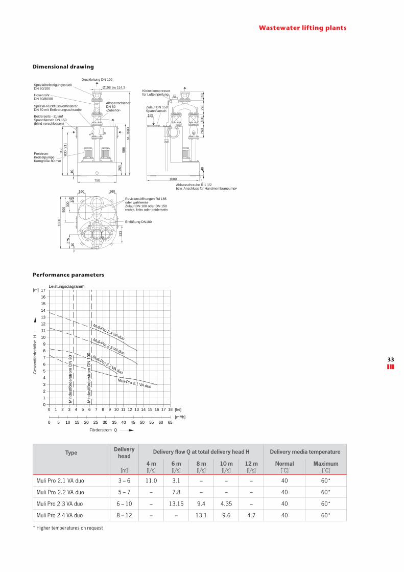
Muli Pro 2.1 VA duo 3 – 6 11.0 3.1 – – – 40 60*
Muli Pro 2.2 VA duo 5 – 7 – 7.8 – – – 40 60*
Muli Pro 2.3 VA duo 6 – 10 – 13.15 9.4 4.35 – 40 60*
Muli Pro 2.4 VA duo 8 – 12 – – 13.1 9.6 4.7 40 60*
Dimensional drawing
Kleinstkompressorfür Lufteinperlung
Ablassschraube R 1 1/2bzw. Anschluss für Handmembranpumpe
260
180
270
160
1000
48
Zulauf DN 150Spannflansch125
SpezialbefestigungsstückDN 80/100
HosenrohrDN 80/80/80
Spezial-RückflussverhindererDN 80 mit Entleerungsschraube
AbsperrschieberDN 80 -Zubehör-
Beiderseits - Zulauf Spannflansch DN 150(blind verschlossen)
Druckleitung DN 100
Ø108 bis 114,3
Freistrom-KreiselpumpeKorngröße 80 mm
988
ca. 1
600
750
10
265
830
(Z1)
938
300 12
5
1000
275
10
160 160
500
333
Revisionsöffnungen Rd 185oder wahlweiseZulauf DN 100 oder DN 150rechts, links oder beiderseits
Entlüftung DN100
Schaltgerät steckerfertig(250 x 195 x 100)
Anschlusskabel1,5 m lang mitCEKON-Stecker 16 A
Anschlusspneum. Steuerleitung
Motorkabel(4 m lang) Anschluss
Kleinstkompressor
Anschlusspneum. Steuerleitung"ALARM 1"
Anschluss fürpotentialfreieSammelstörmeldungund Betriebsmeldung
Anschluss für Notstromversorgung
Leistungsdiagramm Toleranzen ISO 2548/C17161514131211109876543210
0 1 2 3 4 5 6 7 8 9 10 11 12 13 14 15 16 17 18
0 5 10 15 20 25 30 35 40 45 50 55 60 65
Min
dest
förd
erst
rom
DN
80
Min
dest
förd
erst
rom
DN
100
[m]
[l/s]
[m³/h]
Förderstrom Q
Ges
amtfö
rder
höhe
H Muli-Pro 2.3 VA duo
Muli-Pro 2.4 VA duo
Muli-Pro 2.2 VA duo
Muli-Pro 2.1 VA duo
* Higher temperatures on request
33
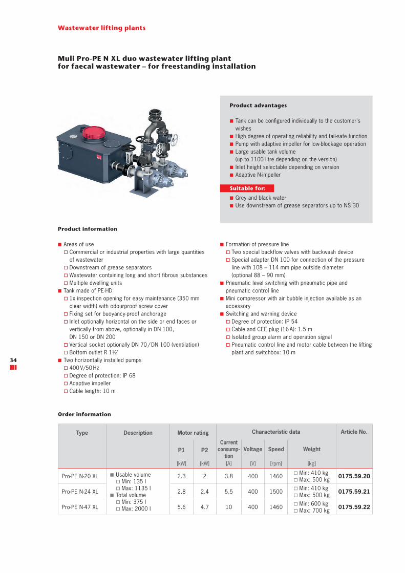
Muli Pro-PE N XL duo wastewater lifting plantfor faecal wastewater – for freestanding installation
Product information
■ Areas of use � Commercial or industrial properties with large quantities of wastewater
� Downstream of grease separators � Wastewater containing long and short fibrous substances � Multiple dwelling units
■ Tank made of PE-HD � 1x inspection opening for easy maintenance (350 mm clear width) with odourproof screw cover
� Fixing set for buoyancy-proof anchorage � Inlet optionally horizontal on the side or end faces or vertically from above, optionally in DN 100, DN 150 or DN 200
� Vertical socket optionally DN 70 / DN 100 (ventilation) � Bottom outlet R 1½"
■ Two horizontally installed pumps � 400 V/50 Hz � Degree of protection: IP 68 � Adaptive impeller � Cable length: 10 m
■ Formation of pressure line � Two special backflow valves with backwash device � Special adapter DN 100 for connection of the pressure line with 108 – 114 mm pipe outside diameter (optional 88 – 90 mm)
■ Pneumatic level switching with pneumatic pipe and pneumatic control line
■ Mini compressor with air bubble injection available as an accessory
■ Switching and warning device � Degree of protection: IP 54 � Cable and CEE plug (16 A): 1.5 m � Isolated group alarm and operation signal � Pneumatic control line and motor cable between the lifting plant and switchbox: 10 m
Product advantages
■ Tank can be configured individually to the customer's wishes
■ High degree of operating reliability and fail-safe function ■ Pump with adaptive impeller for low-blockage operation ■ Large usable tank volume (up to 1100 litre depending on the version)
■ Inlet height selectable depending on version ■ Adaptive N-impeller
Wastewater lifting plants
Type Description Motor rating Characteristic data Article No.
P1 P2Current
consump-tion
Voltage Speed Weight
[kW] [kW] [A] [V] [rpm] [kg]
Pro-PE N-20 XL ■ Usable volume � Min: 135 l � Max: 1135 l
■ Total volume � Min: 375 l � Max: 2000 l
2.3 2 3.8 400 1460 � Min: 410 kg � Max: 500 kg 0175.59.20
Pro-PE N-24 XL 2.8 2.4 5.5 400 1500 � Min: 410 kg � Max: 500 kg 0175.59.21
Pro-PE N-47 XL 5.6 4.7 10 400 1460 � Min: 600 kg � Max: 700 kg 0175.59.22
Order information
Suitable for:
■ Grey and black water ■ Use downstream of grease separators up to NS 30
34

Wastewater lifting plants
Performance parameters
Type Delivery head
Delivery flow Q at total delivery head H Delivery media temperature
[m]4 m[l/s]
6 m[l/s]
8 m[l/s]
10 m[l/s]
12 m[l/s]
14 m[l/s]
16 m[l/s]
Normal[˚C]
Maximum[˚C]
Pro-PE N-20 XL 2 – 9 28.5 18.0 8.3 – – – – 40 60*
Pro-PE N-24 XL 2 – 11.2 37.5 28.5 19.4 10.5 – – – 40 60*
Pro-PE N-47 XL 2 – 16.4 53.5 46.2 38.7 30.0 21.0 13.5 6.0 40 60*
Dimensional drawing
Lüftung(DN70 oder DN100) Revisionsdeckel
Schiebersaugseitig
Schieberdruckseitig
Grundablass
Druckabgang mit Spezialbefestigungsstück DN100
*
*
*
*
*
* Zulaufseite und Zulaufdurchmesser (DN100, DN150, DN200) wählbar Lieferumfang: 1 Zulauf nach Wahl
*
*
780
ca. 1
375
- 180
0
2200 - 34001150 - 2000
375
- 132
556
0 - 1
510
Abstand des Zulaufs wählbar
663
- 161
3
n = 1450 U/min
453627189 9081726354
12963 3027242118150
2
4
6
8
10
12
14
16
Ges
amtfö
rder
höhe
H
[m]
Förderstrom Q162153
4542393633
99 144135126117108
18
20
545148
189180171
Min
dest
förd
er-
stro
m D
N10
0
198 [m³/h]
[l/s]
N-20 N-24N-47
Leistungsdiagramm
The ACO Muli Pro-PE N XL lifting plant
The new model can be used for faecal, non-faecal and treated wastewater from grease separators. The application areas are commercial or industrial properties which produce very large quantities of wastewater (with both long and short-fibre substances).The new ACO Muli Pro-PE N XL lifting plant has a range of product advantag-es on offer. The robust tank made of polyethylene (PE-HD) with large usable volume of up to 1100 l can be delivered with a far larger capacity, individually matched to the customer's wishes. The inlet height (between 375 and 1325 mm depending on the version) and inlet side, like the tank length, is freely selectable. Service friendliness was also a focal point in the development: The pump is installed horizontally. The advantage: Volute casings of vertically installed pumps have to be ventilated so that the pumping operation can start. This is generally done by means of a hose con-nection which is fed back into the tank. During operation this hose connection can become blocked up by foreign bod-ies and the pump thus becomes blocked too. In horizontally installed pumps this hose connection is not required, as the pump ventilates itself via the pressure line. Pumps of this type can also be replaced or repaired during on-going operation – thanks to a gate valve in the inlet and discharge side – without having to drain the tank.
* larger tanks and pumps possible on request
35

Wastewater lifting plants
Upstream tank plants
Upstream tanks with eccentric screw pumps are always required if greasy kitchen wastewater has to be pumped or lifted from the "place of production" to the separator. The focus here is clearly on low-turbulence transport; under no circumstances may the dissolved greases be allowed to be mixed with the other wastewater; keyword: Emulsion. The eccentric screw pump belongs to the group of displacement pumps. Its main components are the rotating rotor, the stator, the gearbox and the drive motor. This pump type is not compa-rable with standard wastewater pumps and has several special features. One of these special features is the uniform pressure and flow rate generated with each rotation of the rotor. If the pressure line is shut off due to ignorance or become blocked
during operation, the pumps continue to pump until a pipe or connection bursts. Restriction of the pump by backpressure, as in a comparable centrifugal pump, does not occur here. Furthermore, displacement pumps are usually self-priming, the medium can be drawn through the pump at a higher level. This enables very variable special solutions, e.g. installation of pumps mounted separately on the wall and the tank in a shaft.Sensors in the winding of the motor and the stator effectively prevent overheating of the components and are evaluated via the ACO MultiControl control.
Installation examples for ACO upstream tank plants (special solutions on request)36
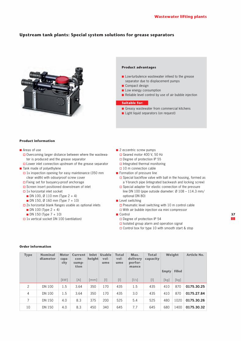
Wastewater lifting plants
Upstream tank plants: Special system solutions for grease separators
Product advantages
■ Low-turbulence wastewater infeed to the grease separator due to displacement pumps
■ Compact design ■ Low energy consumption ■ Reliable level control by use of air bubble injection
Product information
■ Areas of use � Overcoming larger distance between where the wastewa-ter is produced and the grease separator
� Lower inlet connection upstream of the grease separator ■ Tank made of polyethylene
� 1x inspection opening for easy maintenance (350 mm clear width) with odourproof screw cover
� Fixing set for buoyancy-proof anchorage � Screen insert positioned downstream of inlet � 1x horizontal inlet socket ■ DN 100, Ø 110 mm (Type 2 + 4) ■ DN 150, Ø 160 mm (Type 7 + 10)
� 2x horizontal blank flanges usable as optional inlets ■ DN 100 (Type 2 + 4) ■ DN 150 (Type 7 + 10)
� 1x vertical socket DN 100 (ventilation)
■ 2 eccentric screw pumps � Geared motor 400 V, 50 Hz � Degree of protection IP 55 � Integrated thermal monitoring � 10 m connection cable
■ Formation of pressure line � Special backflow valve with ball in the housing, formed as a Y-branch pipe (integrated backwash and locking screw)
� Special adapter for elastic connection of the pressure line DN 100 (pipe outside diameter: Ø 108 – 114.3 mm/optional DN 80)
■ Level switching � Pneumatic level switching with 10 m control cable � With air bubble injection via mini compressor
■ Control � Degree of protection IP 54 � Isolated group alarm and operation signal � Control box for type 10 with smooth start & stop
Order information
Type Nominal diameter
Motorcapa-city
Current con-
sump-tion
Inlet height
Usable vol-ume
Total vol-ume
Max. delivery perfor-mance
Total capacity
Weight Article No.
Empty Filled
[kW] [A] [mm] [l] [l] [l/s] [l] [kg] [kg]
2 DN 100 1.5 3.64 350 170 435 1.5 435 410 870 0175.30.25
4 DN 100 1.5 3.64 350 170 435 3.0 435 410 870 0175.27.84
7 DN 150 4.0 8.3 375 200 525 5.4 525 480 1020 0175.30.26
10 DN 150 4.0 8.3 450 340 645 7.7 645 680 1400 0175.30.32
Suitable for:
■ Greasy wastewater from commercial kitchens ■ Light liquid separators (on request)
37
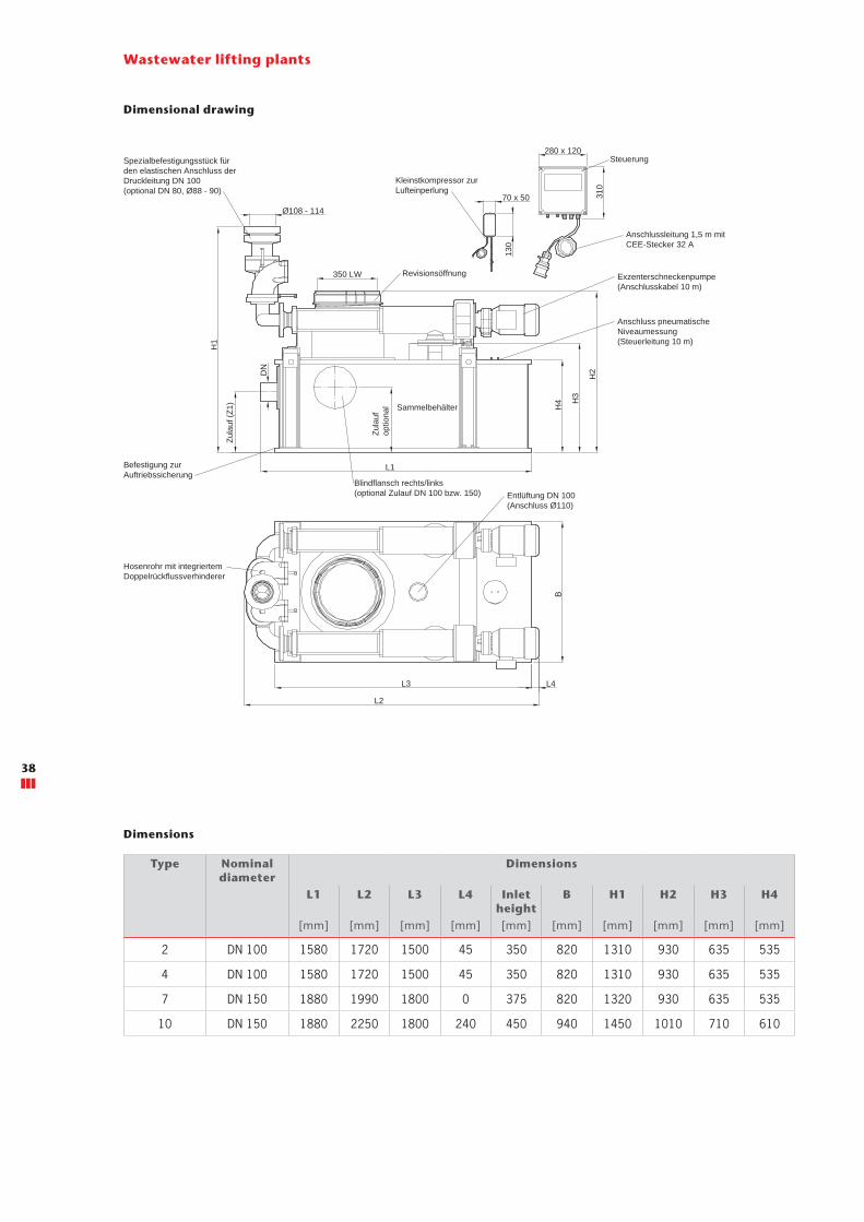
Wastewater lifting plants
Dimensional drawing
Zula
ufop
tiona
l
L1
L4L3
L2
280 x 120
310
B
Ø108 - 114
DN
H1
H4 H
3
H2
70 x 50
350 LW
Zula
uf (Z
1)
130
Steuerung
Anschlussleitung 1,5 m mitCEE-Stecker 32 A
Exzenterschneckenpumpe(Anschlusskabel 10 m)
Anschluss pneumatischeNiveaumessung(Steuerleitung 10 m)
Sammelbehälter
Kleinstkompressor zurLufteinperlung
Revisionsöffnung
Befestigung zurAuftriebssicherung
Hosenrohr mit integriertemDoppelrückflussverhinderer
Spezialbefestigungsstück fürden elastischen Anschluss derDruckleitung DN 100(optional DN 80, Ø88 - 90)
Blindflansch rechts/links(optional Zulauf DN 100 bzw. 150) Entlüftung DN 100
(Anschluss Ø110)
Type Nominal diameter
Dimensions
L1 L2 L3 L4 Inlet height
B H1 H2 H3 H4
[mm] [mm] [mm] [mm] [mm] [mm] [mm] [mm] [mm] [mm]
2 DN 100 1580 1720 1500 45 350 820 1310 930 635 535
4 DN 100 1580 1720 1500 45 350 820 1310 930 635 535
7 DN 150 1880 1990 1800 0 375 820 1320 930 635 535
10 DN 150 1880 2250 1800 240 450 940 1450 1010 710 610
Dimensions
38

Accessories
Wastewater lifting plants
Figure Designation Suitable for Description Article No.
Signalling unit with
GSM module
■ Grease layer thickness measuring device
■ Odour neutralisation ■ Upstream tank plant
� duo ■ Sinkamat-K (underfloor)
� duo ■ All Muli lifting plants ■ Muli-Max-F
■ Mains-independent alarm ■ Visual and acoustic alarm signalling ■ Freely configurable inputs
� 6 digital � 2 analog
■ 1 alarm output 12 V ■ Incl. GSM antenna (2.5 m cable) ■ Forwarding of the alarm to mobile phones by SMS text messaging
■ For installation outside the Ex zone ■ Housing: 178 x 125 x 102 mm (L x H x D)
■ Plug-in card for standard SIM card ■ Degree of protection: IP54 (with mounted antenna connector IP44)
■ Operating voltage: 230 V/AC, 50/60 Hz
0150.46.94
Signalling unit
■ All Muli wastewater lifting plants
■ duo upstream tank plant ■ Muli-Max-F ■ Sinkamat-S ■ Sinkamat-Z ■ Sinkamat-K (underfloor)
� duo
Self-charging ■ With floating contact ■ Visual and acoustic ■ Without contactor ■ For installation outside the Ex zone ■ Housing: 175 x 125 x 75 mm (L x H x D)
■ Degree of protection: IP65 ■ Operating voltage: 230 V/AC, 50/60 Hz
■ Ready to plug in, with cable: 2 m
0150.26.73
Connection and flood
module set
■ All wastewater lifting plants
■ Upstream tank plant � duo
■ For signalling a leakage triggered, e.g. by a pipe burst
■ For electrically conductive liquids ■ With floating contact ■ Visual and acoustic alarm signalling (approx. 80 dB)
■ Housing: 160 x 120 x 75 mm (L x H x D)
■ Degree of protection: IP 65 ■ Operating voltage: 230 V/AC, 50/60 Hz
■ Ready to plug in ■ Cable length: 1.4 m ■ Flood detector with cable (10 m)
0150.34.75
39
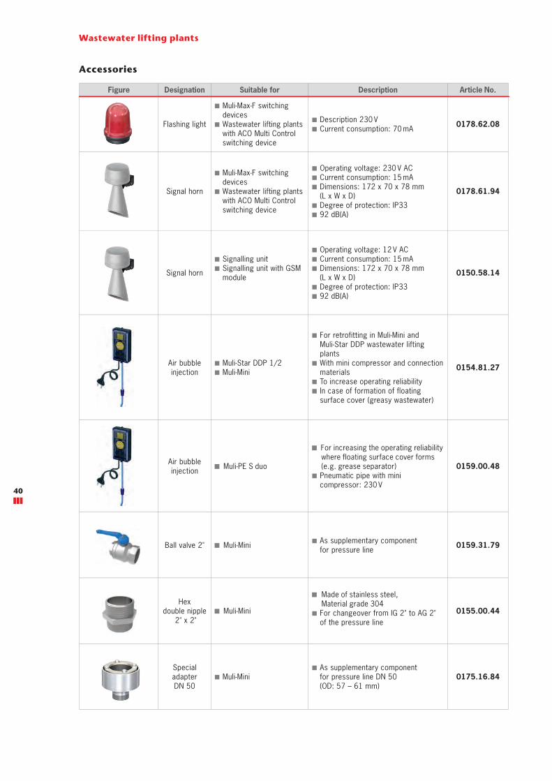
Accessories
Wastewater lifting plants
Figure Designation Suitable for Description Article No.
Flashing light
■ Muli-Max-F switching devices
■ Wastewater lifting plants with ACO Multi Control switching device
■ Description 230 V ■ Current consumption: 70 mA 0178.62.08
Signal horn
■ Muli-Max-F switching devices
■ Wastewater lifting plantswith ACO Multi Control switching device
■ Operating voltage: 230 V AC ■ Current consumption: 15 mA ■ Dimensions: 172 x 70 x 78 mm (L x W x D)
■ Degree of protection: IP33 ■ 92 dB(A)
0178.61.94
Signal horn
■ Signalling unit ■ Signalling unit with GSM module
■ Operating voltage: 12 V AC ■ Current consumption: 15 mA ■ Dimensions: 172 x 70 x 78 mm (L x W x D)
■ Degree of protection: IP33 ■ 92 dB(A)
0150.58.14
Air bubble injection
■ Muli-Star DDP 1/2 ■ Muli-Mini
■ For retrofitting in Muli-Mini andMuli-Star DDP wastewater lifting plants
■ With mini compressor and connection materials
■ To increase operating reliability ■ In case of formation of floatingsurface cover (greasy wastewater)
0154.81.27
Air bubble injection Muli-PE S duo
For increasing the operating reliability where floating surface cover forms (e.g. grease separator)
■ Pneumatic pipe with mini compressor: 230 V
0159.00.48
Ball valve 2" Muli-Mini ■ As supplementary componentfor pressure line 0159.31.79
Hexdouble nipple
2" x 2" Muli-Mini
Made of stainless steel, Material grade 304
■ For changeover from IG 2" to AG 2"of the pressure line
0155.00.44
SpecialadapterDN 50
■ Muli-Mini ■ As supplementary componentfor pressure line DN 50 (OD: 57 – 61 mm)
0175.16.84
40

Wastewater lifting plants
Figure Designation Suitable for Description Article No.
SpecialadapterDN 50
Muli-Mini As supplementary component for pressure line DN 50 (OD: 48 – 52 mm)
0175.32.32
Inlet socket DN 50 ■ Muli-Mini
■ Made of plastic ■ For lateral inlet option ■ For on-site installation ■ Weight: 0.1 kg
2410.00.04
Inlet stop valve
DN 50 ■ Muli-Mini
■ Made of PVC ■ DN 50 ■ With sealing ring to DIN 19538
0175.18.33
Stop valveDN 80 ■ Muli-Star DDP 1/2
■ Made of cast iron ■ 8 bolts and nuts ■ 1 seal DN 80 ■ Overall length: 180 mm ■ Weight: 21 kg
0154.51.93
Stop valveDN 80 ■ Wastewater lifting plants
■ Made of cast iron ■ For pressure line ■ Overall length: 180 mm ■ Weight: 21 kg
0159.09.89
Stop valveDN 100 ■ Wastewater lifting plants
■ Made of cast iron ■ For pressure line ■ Overall length: 190 mm ■ Weight: 32 kg
0159.09.90
Fixing kit ■ Stop valve � 0159.09.89
■ 8 bolts and nuts ■ 1 seal 0159.00.19
Fixing kit ■ Stop valve � 0159.09.90
■ 8 bolts and nuts ■ 1 seal 0159.00.20
41
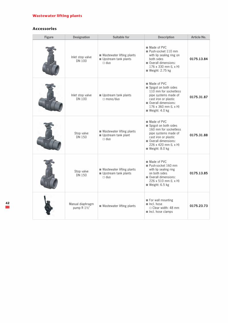
Wastewater lifting plants
Accessories
Figure Designation Suitable for Description Article No.
Inlet stop valve DN 100
■ Wastewater lifting plants ■ Upstream tank plants
� duo
■ Made of PVC ■ Push-socket 110 mm with lip sealing ring on both sides
■ Overall dimensions: 176 x 330 mm (L x H)
■ Weight: 2.75 kg
0175.13.84
Inlet stop valve DN 100
■ Upstream tank plants � mono/duo
■ Made of PVC ■ Spigot on both sides 110 mm for socketless pipe systems made of cast iron or plastic
■ Overall dimensions: 176 x 360 mm (L x H)
■ Weight: 4.0 kg
0175.31.87
Stop valve DN 150
■ Wastewater lifting plants ■ Upstream tank plant
� duo
■ Made of PVC ■ Spigot on both sides 160 mm for socketless pipe systems made of cast iron or plastic
■ Overall dimensions: 226 x 420 mm (L x H)
■ Weight: 8.0 kg
0175.31.88
Stop valve DN 150
■ Wastewater lifting plants ■ Upstream tank plants
� duo
■ Made of PVC ■ Push-socket 160 mm with lip sealing ring on both sides
■ Overall dimensions: 226 x 510 mm (L x H)
■ Weight: 6.5 kg
0175.13.85
Manual diaphragm pump R 1½" ■ Wastewater lifting plants
■ For wall mounting ■ Incl. hose
� Clear width: 48 mm ■ Incl. hose clamps
0175.23.73 42
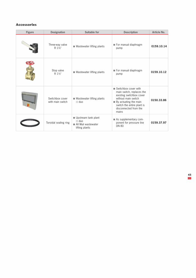
Accessories
Figure Designation Suitable for Description Article No.
Three-way valve R 1½" ■ Wastewater lifting plants ■ For manual diaphragm
pump 0159.10.14
Stop valve R 1½" ■ Wastewater lifting plants ■ For manual diaphragm
pump 0159.10.12
Switchbox coverwith main switch
■ Wastewater lifting plants � duo
■ Switchbox cover with main switch, replaces the existing switchbox cover without main switch
■ By actuating the main switch the entire plant is disconnected from the mains
0150.33.86
Toroidal sealing ring
■ Upstream tank plant � duo
■ All Muli wastewater lifting plants
■ As supplementary com-ponent for pressure line DN 80
0159.37.97
43

44

Pu
mp
ing
sta
tio
ns
Pumping stations –Product Overview
In several construction projects a pumping station is installed in the ground outside the building instead of a freestanding waste-water lifting plant installation in the building.The advantages are not only the space savings but also the ability to also safely drain away rainwater falling outside the building.The size of the pumping station to be installed depends on the flow rate discharged or the nominal size of the upstream separator. The tanks of the ACO pumping stations are made of polyethylene and are characterised, among other things, by their high stability, good resistance and maximum protection against buoyancy. ACO pumping stations are built according to a modular principle: the customer can choose the load class, the control, the type of level measurement, the pump and diverse accessories.If a shaft is already available on site or if it is to be renovated, the ACO Powerlift installation kit in dimensions DN 50 or DN 100 offers the solution. This preassembled installation can be placed in the shaft easily and adapted to the given conditions on site. Here too it is possible to choose between a large number of pumps for black or grey water and diverse accessories.
45

Basic principles
Protection against backflow
In DIN 1986-100 "Drainage systems on private ground" and EN 12056 "gravity drainage systems inside buildings" it is specified that wastewater produced below the backflow level and rainwater from surfaces below the backflow level must be fed, backflow free, into the public sewers via an automatically operating lifting plant/pumping station. The basic principle when designing a drainage system is "to guide surface water away from the building and not to draw it into the building". Accordingly, rainfall runoff areas must be drained via separate pumping sta-tions outside the building. All sanitary appliances located above the backflow level are to be drained with natural slope (gravity principle); the wastewater from these sanitary appliances must not be drained via backflow stops and only in absolutely necessary exceptional cases (e.g. renova-tion of old buildings) may it be drained via lifting plants/pumping stations. If the competent authority has not defined the backwater level, the road level at the connection point is deemed to be the backflow level.
Electrical installation
The electrical installation must be carried out by a qualified electrician. Switching devices and signalling units must be installed in a dry, easily accessible place. The signalling unit must also be installed in a place where it can be easily seen and heard.
Installation
Usable volume The usable volume – also called required impoundment volume – is generally the term used to describe the volume between the pump switching on and switching off point. The usable volume must always be taken into account in the design of the pumping station.For substances and liquids which spread harmful or unpleasant vapours or odours, which attack the materials of the drainage installations or disrupt operations, plants must be installed upstream of them, which prevent these substances and liquids from penetrating the wastewater lifting plant. Such plants are, in particular:
Buoyancy protectionBuoyancy protection is the fixing of a plant/pump onto the floor (or onto the pump shaft in the ground), to prevent it from floating up in case of flooding (or raised groundwater level) of the area, as damage to connections/pipes could occur, which could cause the medium to leak. The buoyancy protection is located directly on tanks or is installed subse-quently or is already cast on. It should be ensured that the plant/pump is securely stood on the ground, protected against twisting, and therefore cannot start to move or turn.
Oil or petrol interceptors to EN 858/DIN 1999-100, fuel oil valves to DN 4043, demulsifiers, grease separators to EN 1825/DIN 4040-100, starch separa-tors to factory standards, grit and sludge traps and neutralisation plants.
Shaft / manhole covers
Load classes Tonnes
A 15 Walk-on-able 1.5
B 125 car-trafficable 12.5
D 400 truck-trafficable 40.0
Pressure line a) Backflow level The backflow level is the highest point in an installation up to which the contaminated water can rise. The backflow level is located in the area of the largest cross-section widening. Installations should be designed so that the water in the sewer cannot flow back into the pumping station. This could happen in the event of storms, floods and heavy rainfall events, if the municipal sewers are not designed for such quantities. Damage caused by this is not covered by insurance companies and only in rare cases are claims legally enforceable. The operator/owner is responsible for protect-ing the building. Information about the height of the backflow level is given in the local byelaws. b) Backflow loop A backflow loop constitutes artificially raised pipe routing above the backflow level, so that backflowing water can be distributed in all lower lying free spaces first. As it can be assumed that an adequate volume is available in the overall pipe system, the backflow loop constitutes the most reliable alternative against backflow. In case of poor/lack of backflow protection the installer or design engineer is liable.
46
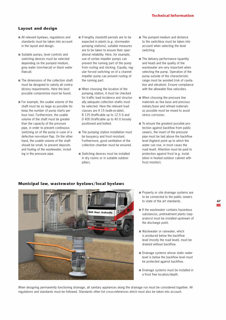
47
Technical Information
Layout and design
■ All relevant byelaws, regulations and standards must be taken into account in the layout and design.
■ Suitable pumps, level controls and switching devices must be selected depending on the pumped medium, grey water (non-faecal) or black water (faecal).
■ The dimensions of the collection shaft must be designed to satisfy all contra-dictory requirements. Here the best possible compromise must be found.
■ For example, the usable volume of the shaft must be as large as possible (to keep the number of pump starts per hour low). Furthermore, the usable volume of the shaft must be greater than the capacity of the pressure pipe, in order to prevent continuous switching on of the pump in case of a defective non-return flap. On the other hand, the usable volume of the shaft should be small, to prevent deposits and fouling of the wastewater, includ-ing in the pressure pipe.
Municipal law, wastewater byelaws/local byelaws
■ Property or site drainage systems are to be connected to the public sewers to state of the art standards.
■ If the wastewater contains hazardous substances, pretreatment plants (sep-arators) must be installed upstream of the discharge point.
■ Wastewater or rainwater, which is produced below the backflow level (mostly the road level), must be drained without backflow.
■ Drainage systems whose static water level is below the backflow level must be protected against backflow.
■ Drainage systems must be installed in a frost free location/depth.
When designing permanently functioning drainage, all sanitary appliances along the drainage run must be considered together. All regulations and standards must be followed. Standards often list cross-references which must also be taken into account.
47
■ If lengthy standstill periods are to be expected in plants (e.g. stormwater pumping stations), suitable measures are to be taken to ensure their oper-ational reliability. Here, for example, use of vortex impeller pumps can prevent the running part of the pump from rusting and sticking. Equally, reg-ular forced switching on of a channel impeller pump can prevent rusting of the running part.
■ When choosing the location of the pumping station, it must be checked for traffic load incidence and structur-ally adequate collection shafts must be selected. Here the relevant load classes are A 15 (walk-on-able), B 125 (trafficable up to 12.5 t) and D 400 (trafficable up to 40 t) loosely positioned and bolted.
■ The pumping station installation must be buoyancy and frost resistant. Furthermore, good ventilation of the collection chamber must be ensured.
■ Switching devices must be installed in dry rooms or in suitable outdoor pillars.
■ The pumped medium and distance to the switchbox must be taken into account when selecting the level switching
■ The delivery performance (quantity and head) and the quality of the wastewater are very important when selecting the pump. Operation of the pump outside of the characteristic range must be avoided (risk of cavita-tion and vibration). Ensure compliance with the allowable flow velocities.
■ When choosing the pressure line materials as few base and precious metals/base and refined materials as possible must be mixed to avoid stress corrosion.
■ To ensure the greatest possible pro-tection against backflow from public sewers, the invert of the pressure pipe must be laid above the backflow level (highest point up to which the water can rise, in most cases the road level). Attention must be paid to protection against frost (e.g. instal-lation in heated outdoor cabinet with frost monitor).
Technical Information
State-of-the-art
EN 12056-1 Gravity drainage systems inside buildings
Backflow protection Wastewater produced below the backflow level must be fed into the drainage system via an automatic wastewater lifting plant. Backflow stops are allowed in exceptional cases.
EN 752-4 Drain and sewer systems outside buildings
The drainage system must be designed for protection against flooding and over-load in case of rainfall events with defined intensities and frequencies, taking into account the backflow lines.
EN 858-2 Separator systems for light liquids
The light liquid must not escape from the separator plant or from the top sections. The separator plant must be connected to the drainage system according to the local regulations.
EN 1825-2 Grease separators
Connections to the drainage system Where there are no official requirements, separator plants for greases must be connected to the sewers as follows. The wastewater must be fed to the separator plant with a free gradient. Separators for greases, whose static water level is below the backflow level (see EN 752-1), must be drained via a downstream lifting plant.
48

Technical Information
Backflow protection for grease separators installed in the ground
■ Note load class of pumping station top section: A (walk-on-able), B (car trafficable), D (truck trafficable) depending on installation site
■ Calculate usable volume of the col-lection shaft, depending on the inlet quantity and the maximum switching frequency of the pump
■ Note the groundwater level and calcu-late the buoyancy behaviour
■ Define the installation depth according to the inlet depth and local frost limit
■ Calculate pump performance required to EN 12056-4
■ Select pump type (channel impeller, vortex impeller, cutting impeller) based on the delivery head, delivery rate and pumped medium
■ Install switchbox in a dry place in the building or on the site in a weather-proof heated outdoor cabinet
■ Install pressure pipe in frostproof place above the backflow level (nor-mally street level) or on the site in a weatherproof heated outdoor cabinet
■ ACO Lipumax grease separatorfor installation in the ground
A
D
B
A B D
C
E
E
C
49

Technical Information
Static water level
Backflow loop
Backflow level
Grease separatorIf the wastewater contains hazardous substances, pretreatment plants (sep-arators) must be installed upstream of the discharge point. Drainage systems must be installed in a frost free location/depth. Municipal law applies.
■ The static water level of a separator installed in the ground is almost always below the backflow level and must be protected against backflow accordingly.
■ Where a raised installed separator is possible, the backflow level must be used as the reference level and not the lowest inlet point. In case of backflow drainage is then no longer ensured and a possible escape of harmful liquids cannot be prevented.
Sampling shaftConnection of the drainage system to the public sewer network to state-of-the-art standards. Municipal law applies.
A
A
C
B
B C Pumping station (Powerlift - P)The separator is connected to the public sewers taking into account the following standards: EN 12056, EN 752 and is to state-of-the-art standards
■ According to the relevant standards, installation of a passive backflow stop is not allowed.
■ 100% backflow protection is only possible by drainage via a pumping station with pressure line routing above the backflow level.
■ A separator installed downstream of the pumping station is designed in accordance with EN 12056 and EN 752.
50

Technical Information
Special featuresThe shafts are made of polyethylene and have a very compact design. The piping is made of stainless steel. The retaining valve, the traverse and the automatic coupling are made of cast iron. The level is measured via a backpressure bell as a standard feature, but on request a 4 – 20 mA pressure pick-up can be used. If the plant is installed downstream of a grease separator, use of the backpressure bell in conjunction with the optional air bubble injection kit is recommended.
Product version
Muli-Max-F prefabricated pumping station (installed in the ground)
Pump types: ■ Five vortex impeller pumps (non-faecal)
■ Three cutter impeller pumps (ATEX conformant: faecal & non-faecal)
Covers: ■ Class A15 (walk-on-able) ■ Class B125 (trafficable by cars) ■ Class D400 (trafficable by trucks)
The covers are designed so that they can be installed on site without compli-cated concreting work, e.g. additional reinforcement in the area of the cover. The pumps are lowered to the automatic above water coupling using the guide belts supplied and are fixed using these belts. This installation or dismantling is carried out without tools.
Area of useThe Muli-Max-F pump shaft is especially suitable for the drainage of detached and multi-dwelling houses, office buildings and industrial buildings and for siphonic drainage. Furthermore, grease separators up to nominal size 4 can be drained. The pumping stations are designed for non-faecal and faecal wastewater and are available as single or twin pumping stations
51
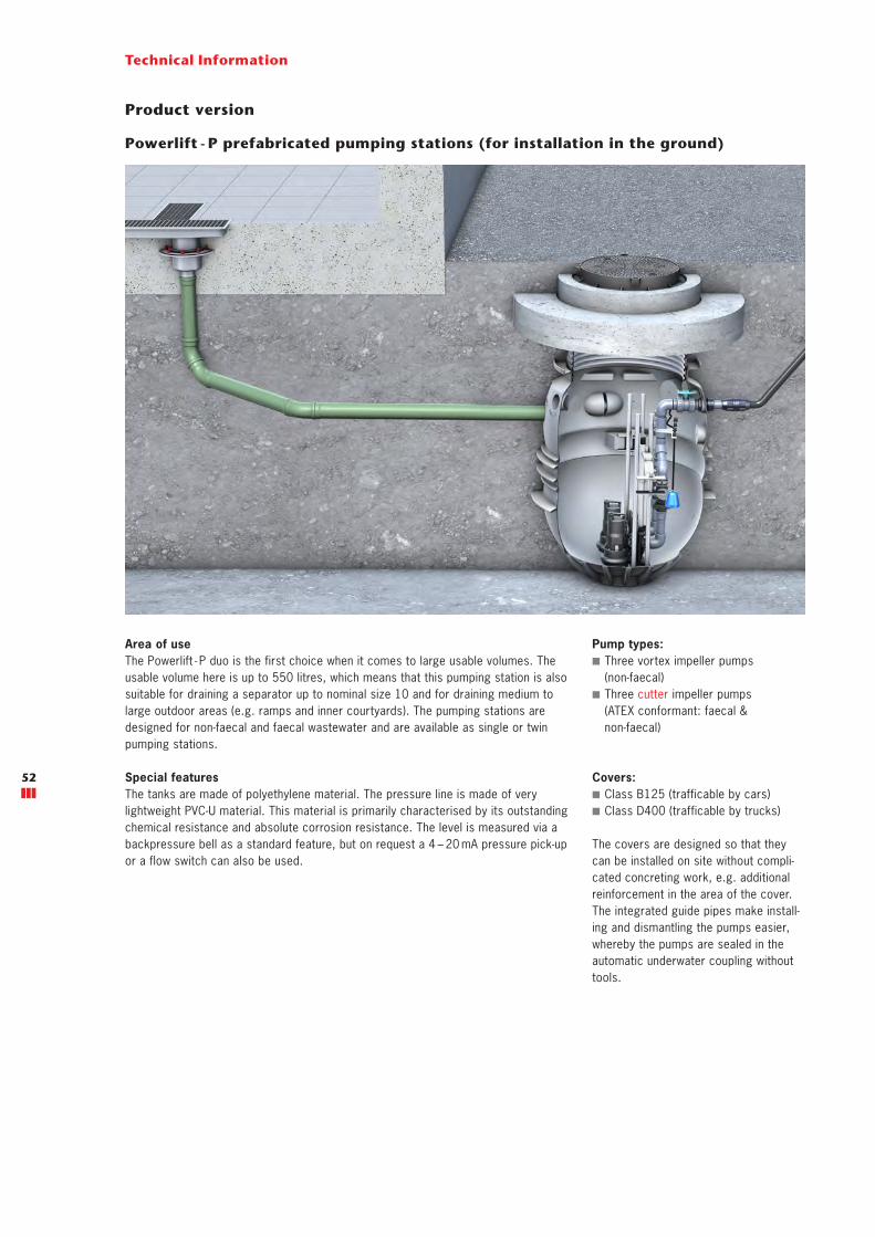
Technical Information
Powerlift - P prefabricated pumping stations (for installation in the ground)
Area of useThe Powerlift - P duo is the first choice when it comes to large usable volumes. The usable volume here is up to 550 litres, which means that this pumping station is also suitable for draining a separator up to nominal size 10 and for draining medium to large outdoor areas (e.g. ramps and inner courtyards). The pumping stations are designed for non-faecal and faecal wastewater and are available as single or twin pumping stations.
Special featuresThe tanks are made of polyethylene material. The pressure line is made of very lightweight PVC-U material. This material is primarily characterised by its outstanding chemical resistance and absolute corrosion resistance. The level is measured via a backpressure bell as a standard feature, but on request a 4 – 20 mA pressure pick-up or a flow switch can also be used.
Pump types: ■ Three vortex impeller pumps (non-faecal)
■ Three cutter impeller pumps (ATEX conformant: faecal & non-faecal)
Covers: ■ Class B125 (trafficable by cars) ■ Class D400 (trafficable by trucks)
The covers are designed so that they can be installed on site without compli-cated concreting work, e.g. additional reinforcement in the area of the cover. The integrated guide pipes make install-ing and dismantling the pumps easier, whereby the pumps are sealed in the automatic underwater coupling without tools.
Product version
52

Technical Information
Product features Muli-Max-F Powerlift - P Powerlift installation kit
Non-faecal and faecal wastewater yes yes yes
Covers A15, B125, D400 B125, D400Depending on thesituation on site
Choice of vortex impeller pumps 5 3 3
Choice of cutter impeller pumps 3 3 3
Choice of channel impeller pumps - - 8
Ready to install yes yes Use of an existing shaft
Usable volume up to 150 litres up to 550 litres Depending on the situation on site
Drainage of grease separators up to nominal size 4 up to nominal size 10 Depending on shaft size
Typical areas of use ■ Private households ■ Office buildings ■ Small industry
■ Industrial buildings ■ Ramps ■ Large roof areas ■ Outdoor areas and courtyards
■ Industrial buildings ■ Ramps ■ Large roof areas ■ Outdoor areas and courtyards
Powerlift installation kit for on-site shafts
Product selection matrix
Pump types: ■ Three vortex impeller pumps (non-faecal) ■ Three cutter impeller pumps (ATEX conformant: faecal & non-faecal)
■ Eight channel impeller pumps
Area of useThe Powerlift installation kit has been designed for on-site shafts, whereby the shaft shape (round or square) is irrelevant. The overall height and equip-ment of the plant can be adapted using the modular principle and thus offer maximum flexibility. The installation kit is suitable for the drainage of detached and multi-dwelling houses, for surface drainage (e.g. ramps, inner courtyards), for business and industrial parks and downstream of diverse separator plants.
Special featuresThe piping is delivered preassembled and is available in DN 50 or DN 100. The pump kit is designed for both non-faecal and faecal wastewater and is available as a mono and a duo version. The kit can be quickly adapted to the respective circumstances on site. The pump kit DN 50, which is mainly made of PVC-U, provides all the necessary materials.The level measurement by means of float switch, pressure pick-up or open backpressure bell can be attached and securely fastened in an optional holder.
Product version
53
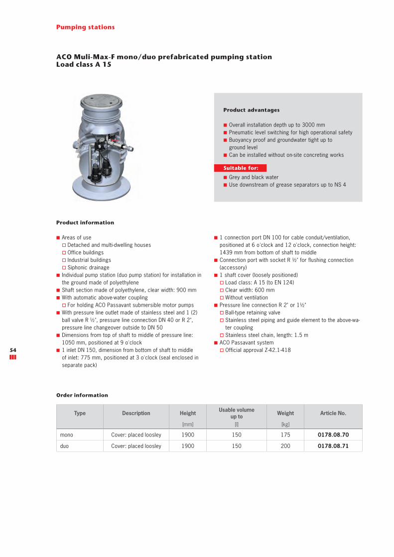
ACO Muli-Max-F mono/duo prefabricated pumping stationLoad class A 15
Product information
■ Areas of use � Detached and multi-dwelling houses � Office buildings � Industrial buildings � Siphonic drainage
■ Individual pump station (duo pump station) for installation in the ground made of polyethylene
■ Shaft section made of polyethylene, clear width: 900 mm ■ With automatic above-water coupling
� For holding ACO Passavant submersible motor pumps ■ With pressure line outlet made of stainless steel and 1 (2) ball valve R ½", pressure line connection DN 40 or R 2", pressure line changeover outside to DN 50
■ Dimensions from top of shaft to middle of pressure line: 1050 mm, positioned at 9 o'clock
■ 1 inlet DN 150, dimension from bottom of shaft to middle of inlet: 775 mm, positioned at 3 o'clock (seal enclosed in separate pack)
■ 1 connection port DN 100 for cable conduit/ventilation, positioned at 6 o'clock and 12 o'clock, connection height: 1439 mm from bottom of shaft to middle
■ Connection port with socket R ½" for flushing connection (accessory)
■ 1 shaft cover (loosely positioned) � Load class: A 15 (to EN 124) � Clear width: 600 mm � Without ventilation
■ Pressure line connection R 2" or 1½" � Ball-type retaining valve � Stainless steel piping and guide element to the above-wa-ter coupling
� Stainless steel chain, length: 1.5 m ■ ACO Passavant system
� Official approval Z-42.1-418
Type Description Height Usable volumeup to Weight Article No.
[mm] [l] [kg]
mono Cover: placed loosley 1900 150 175 0178.08.70
duo Cover: placed loosley 1900 150 200 0178.08.71
Order information
Product advantages
■ Overall installation depth up to 3000 mm ■ Pneumatic level switching for high operational safety ■ Buoyancy proof and groundwater tight up to ground level
■ Can be installed without on-site concreting works
Pumping stations
Suitable for:
■ Grey and black water ■ Use downstream of grease separators up to NS 4
54
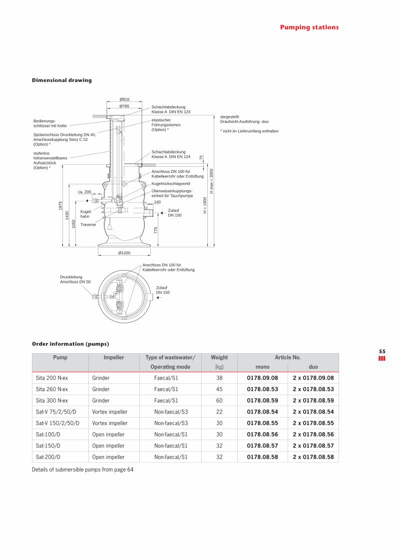
Order information (pumps)
Pumping stations
Dimensional drawing
Pump Impeller Type of wastewater/ Weight Article No.
Operating mode [kg] mono duo
Sita 200 N-ex Grinder Faecal/S1 38 0178.09.08 2 x 0178.09.08
Sita 260 N-ex Grinder Faecal/S1 45 0178.08.53 2 x 0178.08.53
Sita 300 N-ex Grinder Faecal/S1 60 0178.08.59 2 x 0178.08.59
Sat-V 75/2/50/D Vortex impeller Non-faecal/S3 22 0178.08.54 2 x 0178.08.54
Sat-V 150/2/50/D Vortex impeller Non-faecal/S3 30 0178.08.55 2 x 0178.08.55
Sat-100/D Open impeller Non-faecal/S1 30 0178.08.56 2 x 0178.08.56
Sat-150/D Open impeller Non-faecal/S1 32 0178.08.57 2 x 0178.08.57
Sat-200/D Open impeller Non-faecal/S1 32 0178.08.58 2 x 0178.08.58
Details of submersible pumps from page 64
ZulaufDN 150
Ø1200
1050
140
1430
Anschluss DN 100 für Kabelleerrohr oder Entlüftung
1875
775
ca. 200
DruckleitungAnschluss DN 50
Überwasserkupplungs-einheit für Tauchpumpe
Traverse
Kugel-hahn
Kugelrückschlagventil
Ø816
75
Ø785
H =
190
0
SchachtabdeckungKlasse A DIN EN 124
stufenlos höhenverstellbaresAufsatzstück(Option) *
Bedienungs-schlüssel mit Kette
elastischerFührungsriemen(Option) *
Spülanschluss Druckleitung DN 40,Anschlusskupplung Storz C 52 (Option) *
H m
ax =
300
0
Anschluss DN 100 für Kabelleerrohr oder Entlüftung
SchachtabdeckungKlasse A DIN EN 124
Zulauf DN 150
dargestellt:Draufsicht Ausführung -duo
* nicht im Lieferumfang enthalten
55

ACO Muli-Max-F mono/duo prefabricated pumping stationLoad class B 125
Product information
■ Areas of use � Detached and multi-dwelling houses � Office buildings � Industrial buildings � Siphonic drainage
■ Individual pump station (duo pump station) for installation in the ground made of polyethylene
■ Shaft section made of polyethylene, clear width: 900 mm ■ With automatic above-water coupling
� For holding ACO Passavant submersible motor pumps ■ With pressure line outlet made of stainless steel and 1 (2) ball valve R ½", pressure line connection DN 40 or R 2", pressure line changeover outside to DN 50
■ Dimensions from top of shaft to middle of pressure line: 1050 mm, positioned at 9 o'clock
■ 1 inlet DN 150, dimension from bottom of shaft to middle of inlet: 775 mm, positioned at 3 o'clock (seal enclosed in separate pack)
■ 1 connection port DN 100 for cable conduit/ventilation positioned at 6 o'clock and 12 o'clock connection height: 1439 mm from bottom of shaft to middle
■ Connection port with socket R ½" for flushing connection (accessory)
■ 1 manhole cover � Load class: B 125 (to EN 124) � Clear width: 600 mm � Without ventilation, incl. 2 operating keys
■ Pressure line connection R 2" or 1½" � Ball-type retaining valve � Stainless steel piping and guide element to the above-wa-ter coupling
� Stainless steel chain, length: 1.5 m ■ ACO Passavant system
� Official approval Z-42.1-418
Type Description Height Usable volume up to Weight Article No.
[mm] [l] [kg]
mono Cover: placed loosley 1950 150 160 0178.08.72
duo Cover: screwed shut odour-proof 1950 150 160 0178.08.73
mono Cover: placed loosley 1950 150 180 0178.09.04
duo Cover: screwed shut odour-proof 1950 150 180 0178.09.06
Order information
Product advantages
■ Overall installation depth up to 3000 mm ■ Pneumatic level switching for high operational safety ■ Buoyancy proof and groundwater tight up to ground level
■ Can be installed without on-site concreting works ■ Car trafficable
Pumping stations
Suitable for:
■ Grey and black water ■ Use downstream of grease separators up to NS 4
56

Pumping stations
Dimensional drawing
Order information (pumps)
Pump Impeller Type of wastewater/ Weight Article No.
Operating mode [kg] mono duo
Sita 200 N-ex Grinder Faecal/S1 38 0178.09.08 2 x 0178.09.08
Sita 260 N-ex Grinder Faecal/S1 45 0178.08.53 2 x 0178.08.53
Sita 300 N-ex Grinder Faecal/S1 60 0178.08.59 2 x 0178.08.59
Sat-V 75/2/50/D Vortex impeller Non-faecal/S3 22 0178.08.54 2 x 0178.08.54
Sat-V 150/2/50/D Vortex impeller Non-faecal/S3 30 0178.08.55 2 x 0178.08.55
Sat-100/D Open impeller Non-faecal/S1 30 0178.08.56 2 x 0178.08.56
Sat-150/D Open impeller Non-faecal/S1 32 0178.08.57 2 x 0178.08.57
Sat-200/D Open impeller Non-faecal/S1 32 0178.08.58 2 x 0178.08.58
Details of submersible pumps from page 64
ZulaufDN 150
Ø1200
1050
140
1430
Anschluss DN 100 für Kabelleerrohr oder Entlüftung
1875
775
ca. 200
DruckleitungAnschluss DN 50
Überwasserkupplungs-einheit für Tauchpumpe
Traverse
Kugel-hahn
Kugelrückschlagventil
Ø816
125
Ø750
H =
195
0
SchachtabdeckungKlasse B DIN EN 124
stufenlos höhenverstellbaresAufsatzstück(Option) *
Bedienungs-schlüssel mit Kette
elastischerFührungsriemen(Option) *
Spülanschluss Druckleitung DN 40,Anschlusskupplung Storz C 52 (Option) *
H m
ax =
300
0
Anschluss DN 100 für Kabelleerrohr oder Entlüftung
SchachtabdeckungKlasse B DIN EN 124
Zulauf DN 150
dargestellt:Draufsicht Ausführung -duo
* nicht im Lieferumfang enthalten
57

ACO Muli-Max-F mono/duo prefabricated pumping stationLoad class D 400
Product information
■ Areas of use � Detached and multi-dwelling houses � Office buildings � Industrial buildings � Siphonic drainage
■ Individual pump station (duo pump station) for installation in the ground made of polyethylene
■ Shaft section made of polyethylene, clear width: 900 mm ■ With automatic above-water coupling
� For holding ACO Passavant submersible motor pumps ■ With pressure line outlet made of stainless steel and 1 (2) ball valve R ½", pressure line connection DN 40 or R 2", pressure line changeover outside to DN 50
■ Dimensions from top of shaft to middle of pressure line: 1050 mm, positioned at 9 o'clock
■ 1 inlet DN 150, dimension from bottom of shaft to middle of inlet: 775 mm, positioned at 3 o'clock (seal enclosed in separate pack)
■ 1 connection port DN 100 for cable conduit/ventilation positioned at 6 o'clock and 12 o'clock connection height: 1439 mm from bottom of shaft to middle
■ Connection port with socket R ½" for flushing connection (accessory)
■ 1 manhole cover � Load class: D 400 (to EN 124) � Clear width: 600 mm � Without ventilation, incl. 2 operating keys
■ With load distribution slab: 1550/625 x 200 mm made of reinforced concrete
■ With connector � Height: 1400 mm � Height-adjustable, incl. seal
■ Pressure line connection R 2" or 1½" � Ball-type retaining valve � Stainless steel piping and guide element to the above-wa-ter coupling
� Stainless steel chain, length: 1.5 m ■ ACO Passavant system
� Official approval Z-42.1-418
Type Description Height Usable volume up to Weight Article No.
[mm] [l] [kg]
mono Cover: placed loosley 3000 150 1060 0178.09.00
duo Cover: screwed shut odour-proof 3000 150 1060 0178.09.01
mono Cover: screwed shut odour-proof 3000 150 1080 0178.09.05
duo Cover: odourproof bolted 3000 150 1080 0178.09.07
Order information
Product advantages
■ Overall installation depth up to 3000 mm ■ Pneumatic level switching for high operational safety ■ Buoyancy proof and groundwater tight up to ground level
■ Can be installed without on-site concreting works ■ Truck trafficable
Pumping stations
Suitable for:
■ Grey and black water ■ Use downstream of grease separators up to NS 4
58
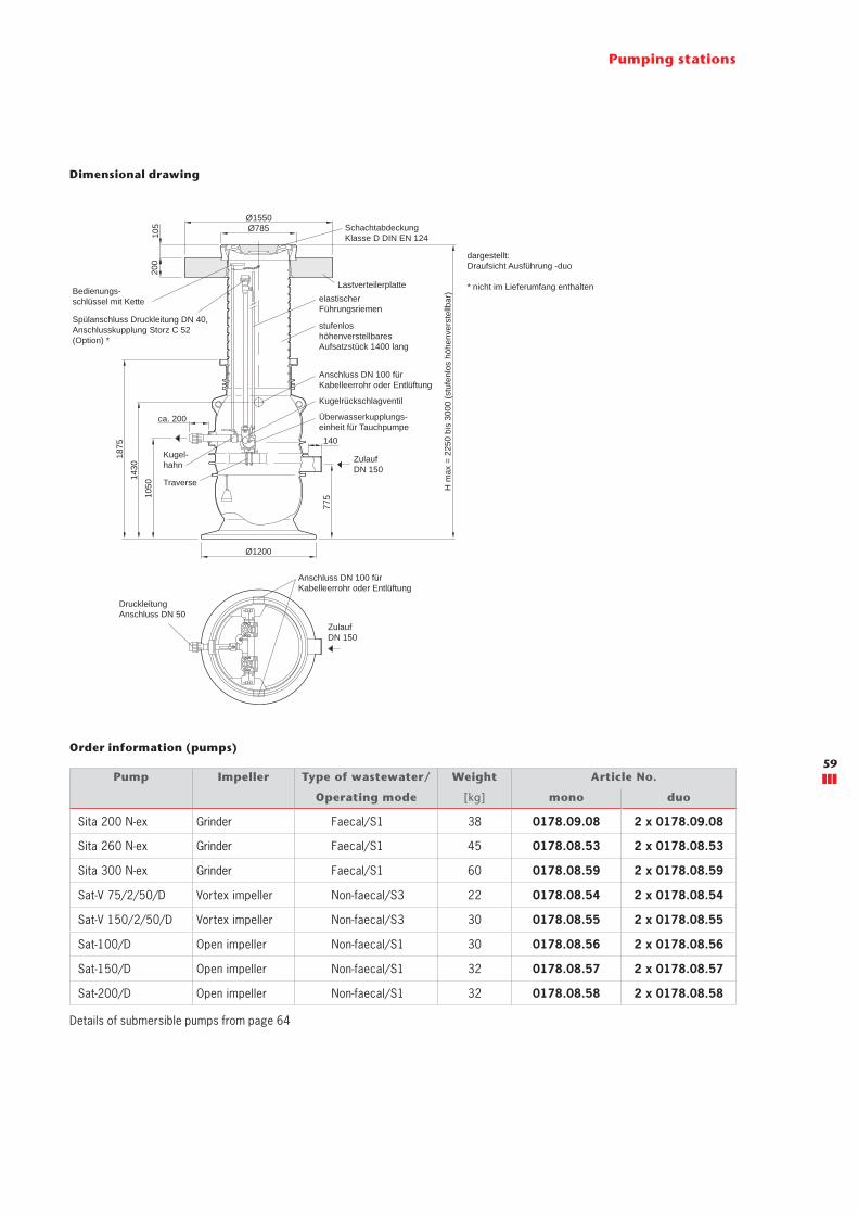
Pumping stations
Dimensional drawing
Pump Impeller Type of wastewater/ Weight Article No.
Operating mode [kg] mono duo
Sita 200 N-ex Grinder Faecal/S1 38 0178.09.08 2 x 0178.09.08
Sita 260 N-ex Grinder Faecal/S1 45 0178.08.53 2 x 0178.08.53
Sita 300 N-ex Grinder Faecal/S1 60 0178.08.59 2 x 0178.08.59
Sat-V 75/2/50/D Vortex impeller Non-faecal/S3 22 0178.08.54 2 x 0178.08.54
Sat-V 150/2/50/D Vortex impeller Non-faecal/S3 30 0178.08.55 2 x 0178.08.55
Sat-100/D Open impeller Non-faecal/S1 30 0178.08.56 2 x 0178.08.56
Sat-150/D Open impeller Non-faecal/S1 32 0178.08.57 2 x 0178.08.57
Sat-200/D Open impeller Non-faecal/S1 32 0178.08.58 2 x 0178.08.58
Order information (pumps)
Details of submersible pumps from page 64
200
105
stufenlos höhenverstellbaresAufsatzstück 1400 lang
Ø1550Ø785
Anschluss DN 100 für Kabelleerrohr oder Entlüftung
Überwasserkupplungs-einheit für Tauchpumpe
Kugelrückschlagventil
ZulaufDN 150
Traverse
Kugel-hahn
Bedienungs-schlüssel mit Kette
Spülanschluss Druckleitung DN 40,Anschlusskupplung Storz C 52 (Option) *
H m
ax =
225
0 bi
s 30
00 (s
tufe
nlos
höh
enve
rste
llbar
)
SchachtabdeckungKlasse D DIN EN 124
elastischerFührungsriemen
Lastverteilerplatte
dargestellt:Draufsicht Ausführung -duo
* nicht im Lieferumfang enthalten
DruckleitungAnschluss DN 50
Anschluss DN 100 für Kabelleerrohr oder Entlüftung
Zulauf DN 150
Ø1200
1050
140
1430
1875
775
ca. 200
59

ACO Powerlift - P duo prefabricated pumping stationLoad class B 125/D 400
Product information
■ Area of use � Downstream of separators � Detached and multi-dwelling houses � Surface drainage, e.g.: � Ramps, inner courtyards, etc. � Trade and industrial buildings
■ Double pumping station for collecting and automatic lifting of faecal and non-faecal wastewater above the backflow level
■ For installation below ground ■ Tank made of polyethylene LLD-PE, Nominal diameter 1320 mm, clear width 1100 mm
■ Traverse made of stainless steel ■ Automatic underwater coupling for retaining ACO submersible pumps with coupling element
■ Piping made of PVC-U � 1x ball valve G 2 made of PVC-U � 2x ball retaining valve G 2 made of cast iron EN-GJL � Flushing pipe connection option
■ Pressure line connection (outside) with compression fitting DN 50 (adapter DN 70, DN 80 as accessory)
� DN 50 for pipe outside Ø 63 mm � DN 70 for pipe outside Ø 75 mm � Dimension from bottom of tank to middle of pressure line 1295 mm, positioned at 3 o'clock
Load class Type Description Usable volume up to Weight Article No.
[l] [kg]
B 125 duo ■ Traverse made of stainless steel ■ Pressure connection DN 50 for pipe outside Ø 63 mm
550 450 0178.13.11
B 125 with top section duo
■ Traverse made of stainless steel ■ Pressure connection DN 50 for pipe outside Ø 63 mm
550 1050 0178.13.12
D 400 with top section duo
■ Traverse made of stainless steel ■ Pressure connection DN 50 for pipe outside Ø 63 mm
550 1050 0178.13.13
Order information
Product advantages
■ Selected material combinations for longer service life
■ Vertically installed ball retaining valve for reliable closing
■ Overall installation depth up to 3000 mm ■ Large usable volume – for surface drainage
Pumping stations
■ 1x connection socket DN 150 with sealing element for inlet pipe, connection to EN 877, dimension from bottom of tank to middle of connection socket 1275 mm, positioned at 7:40 o'clock
■ 2x connection socket DN 100 with sealing element for cable conduit/ventilation, connection to EN 877, dimension from bottom of tank to middle of connection socket 1360 mm, positioned at 4:15 and 10:15 o'clock
■ Use of different level sensors due to universal level switching bracket
■ Largely deposit free collection chamber with spherical bottom ■ Adapter plate Ø 1000/625, H = 150 mm ■ Shaft cover nominal size 600 - classes B 125/D 400 to EN 124, odourproof bolted, H = 125 mm
■ Buoyancy proof where groundwater levels are up to 0.5 m below the ground level
■ Due to a height-adjustable top section it can be installed up to a total installation depth of 3000 mm
■ Installation depths (B 125/D 400): � T1 = min. 630 mm � T3 = min. 955 mm up to max. 1795 mm
■ Top section D 400, cpl. � Top section H = 1600 mm � 2x sealing ring Ø 780 mm, 20 thick � 1x retaining ring Ø 810 mm, 30 thick � Load distribution slab Ø 1550/850, H = 200 mm
Suitable for:
■ Grey and black water ■ Use downstream of grease separators up to NS 10
60

Pumping stations
Dimensional drawing
Pump Impeller Motor rating Type of wastewater/ Weight duo
[kW] Operating mode [kg]
Sita 200 N-ex Grinder 1.50 Faecal/S1 34 2 x 0178.12.85
Sita 300 N-ex Grinder 2.20 Faecal/S1 44 2 x 0178.12.86
Sita 550 N-ex Grinder 5.00 Faecal/S1 72 2 x 0178.12.87
Sat-100/D Vortex impeller 0.88 Non-faecal/S1 24 2 x 0178.12.80
Sat-150/D Vortex impeller 1.10 Non-faecal/S1 27 2 x 0178.12.81
Sat-200/D Vortex impeller 1.50 Non-faecal/S1 28 2 x 0178.12.82
Order information (pumps)
Details of submersible pumps from page 64
B 125 B 125 D400
61
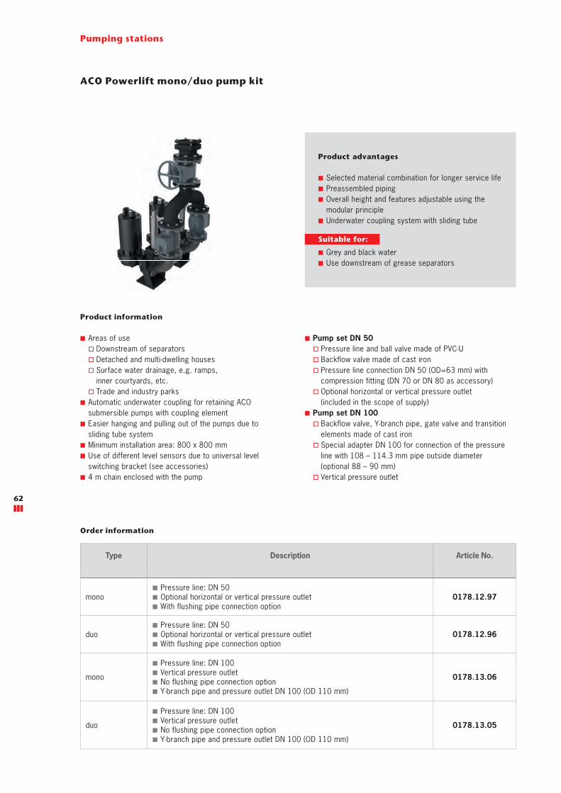
ACO Powerlift mono/duo pump kit
Product information
■ Areas of use � Downstream of separators � Detached and multi-dwelling houses � Surface water drainage, e.g. ramps, inner courtyards, etc.
� Trade and industry parks ■ Automatic underwater coupling for retaining ACOsubmersible pumps with coupling element
■ Easier hanging and pulling out of the pumps due tosliding tube system
■ Minimum installation area: 800 x 800 mm ■ Use of different level sensors due to universal levelswitching bracket (see accessories)
■ 4 m chain enclosed with the pump
■ Pump set DN 50 � Pressure line and ball valve made of PVC-U � Backflow valve made of cast iron � Pressure line connection DN 50 (OD=63 mm) withcompression fitting (DN 70 or DN 80 as accessory)
� Optional horizontal or vertical pressure outlet(included in the scope of supply)
■ Pump set DN 100 � Backflow valve, Y-branch pipe, gate valve and transition elements made of cast iron
� Special adapter DN 100 for connection of the pressure line with 108 – 114.3 mm pipe outside diameter(optional 88 – 90 mm)
� Vertical pressure outlet
Type Description Article No.
mono ■ Pressure line: DN 50 ■ Optional horizontal or vertical pressure outlet ■ With flushing pipe connection option
0178.12.97
duo ■ Pressure line: DN 50 ■ Optional horizontal or vertical pressure outlet ■ With flushing pipe connection option
0178.12.96
mono
■ Pressure line: DN 100 ■ Vertical pressure outlet ■ No flushing pipe connection option ■ Y-branch pipe and pressure outlet DN 100 (OD 110 mm)
0178.13.06
duo
■ Pressure line: DN 100 ■ Vertical pressure outlet ■ No flushing pipe connection option ■ Y-branch pipe and pressure outlet DN 100 (OD 110 mm)
0178.13.05
Order information
Product advantages
■ Selected material combination for longer service life ■ Preassembled piping ■ Overall height and features adjustable using the modular principle
■ Underwater coupling system with sliding tube
Pumping stations
Suitable for:
■ Grey and black water ■ Use downstream of grease separators
62
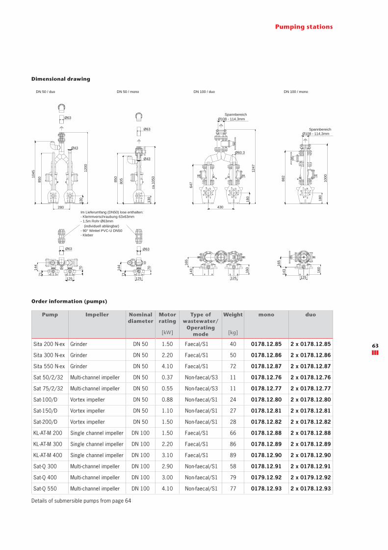
Pumping stations
Dimensional drawing
Pump Impeller Nominal diameter
Motor rating
Type of wastewater/
Operating mode
Weight mono duo
[kW] [kg]
Sita 200 N-ex Grinder DN 50 1.50 Faecal/S1 40 0178.12.85 2 x 0178.12.85
Sita 300 N-ex Grinder DN 50 2.20 Faecal/S1 50 0178.12.86 2 x 0178.12.86
Sita 550 N-ex Grinder DN 50 4.10 Faecal/S1 72 0178.12.87 2 x 0178.12.87
Sat 50/2/32 Multi-channel impeller DN 50 0.37 Non-faecal/S3 11 0178.12.76 2 x 0178.12.76
Sat 75/2/32 Multi-channel impeller DN 50 0.55 Non-faecal/S3 11 0178.12.77 2 x 0178.12.77
Sat-100/D Vortex impeller DN 50 0.88 Non-faecal/S1 24 0178.12.80 2 x 0178.12.80
Sat-150/D Vortex impeller DN 50 1.10 Non-faecal/S1 27 0178.12.81 2 x 0178.12.81
Sat-200/D Vortex impeller DN 50 1.50 Non-faecal/S1 28 0178.12.82 2 x 0178.12.82
KL-AT-M 200 Single channel impeller DN 100 1.50 Faecal/S1 66 0178.12.88 2 x 0178.12.88
KL-AT-M 300 Single channel impeller DN 100 2.20 Faecal/S1 86 0178.12.89 2 x 0178.12.89
KL-AT-M 400 Single channel impeller DN 100 3.10 Faecal/S1 89 0178.12.90 2 x 0178.12.90
Sat-Q 300 Multi-channel impeller DN 100 2.90 Non-faecal/S1 58 0178.12.91 2 x 0178.12.91
Sat-Q 400 Multi-channel impeller DN 100 3.00 Non-faecal/S1 79 0179.12.92 2 x 0179.12.92
Sat-Q 550 Multi-channel impeller DN 100 4.10 Non-faecal/S1 77 0178.12.93 2 x 0178.12.93
Order information (pumps)
Details of submersible pumps from page 64
1200
Ø63
Ø43
125
7013
0
1247
647
430
125
280
180
144
71
160
165
143
125 12516
5
144
180
Ø60.3
Ø63
130
ca.1
05010
45
805 1000
882
850
850
Ø43
Ø63
Ø63
71
70
143 16
0
Im Lieferumfang (DN50) lose enthalten:- Klemmverschraubung 63x63mm- 1,5m Rohr Ø63mm (individuell ablängbar)- 90° Winkel PVC-U DN50- Kleber
Ø108 - 114,3mmSpannbereich
Ø108 - 114,3mmSpannbereich
DN 100 / duoDN 50 / mono DN 100 / monoDN 50 / duo
63
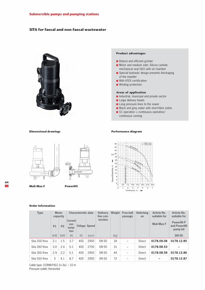
SITA for faecal and non-faecal wastewater
Product advantages
■ Robust and efficient grinder ■ Motor and medium side: Silicon carbide mechanical seal (SiC) with oil chamber
■ Special hydraulic design prevents blockaging of the impeller
■ With ATEX certification ■ Winding protection
Submersible pumps and pumping stations
Type Motorcapacity
Characteristic data Delivery line con-nection
Weight Free ball passage
Switching on
Article No. suitable for
Article No. suitable for
P1 P2
Currentcon-
sump-tion
Voltage SpeedMuli-Max F Powerlift P
and Powerlift pump kit
[kW] [kW] [A] [V] [rpm] [kg] DN 50
Sita 200 N-ex 2.1 1.5 3.7 400 2900 DN 50 34 – Direct 0178.09.08 0178.12.85
Sita 260 N-ex 3.0 2.4 5.1 400 2700 DN 50 31 – Direct 0178.08.53 –
Sita 300 N-ex 2.9 2.2 5.1 400 2900 DN 50 44 – Direct 0178.08.59 0178.12.86
Sita 550 N-ex 5 4.1 8.7 400 2900 DN 50 72 – Direct – 0178.12.87
Order information
Areas of application ■ Industrial, municipal and private sector ■ Large delivery heads ■ Long pressure lines to the sewer ■ Black and grey water with short-fibre solids ■ S1 operation = continuous operation/ continuous running
Dimensional drawings
PowerliftMuli-Max-F
Performance diagram
Cable type: S1RN8-F4G1.5+3x1 – 10 mPressure outlet: Horizontal
64

KL-AT-M for faecal and non-faecal wastewater
Product advantages
■ Open single-channel impeller ■ Large ball passage ■ Motor and medium side: Silicon carbide mechanical seal (SiC) with oil chamber
■ Special hydraulic design prevents blockaging of the impeller
■ With ATEX certification ■ Winding protection
Type Motorcapacity
Characteristic data Delivery line connection
Weight Free ball passage
Switching on
Article No. suitable for
P1 P2
Currentcon-
sump-tion
Voltage Speed Powerlift pump kit
[kW] [kW] [A] [V] [rpm] [kg] DN 100
KL-AT-M 200/4/80 2 1.5 4.1 400 1450 DN 80 66 80 Direct 0178.12.88
KL-AT-M 300/4/80 2.9 2.2 5.8 400 1450 DN 80 86 80 Direct 0178.12.89
KL-AT-M 400/4/80 3.7 3 7.3 400 1450 DN 80 89 80 Direct 0178.12.90
Order information
Submersible pumps and pumping stations
Areas of application ■ Industrial, municipal and private sector ■ Highly soiled grey and black water ■ S1 operation = continuous operation/ continuous running
Dimensional drawings
Powerlift
Performance diagram
Cable type: S1RN8-F4G1.5+3x1 – 10 mPressure outlet: Horizontal
65
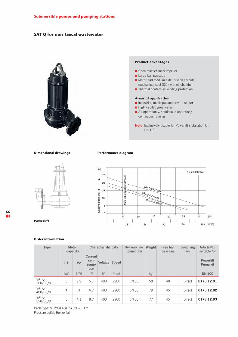
SAT Q for non-faecal wastewater
Product advantages
■ Open multi-channel impeller ■ Large ball passage ■ Motor and medium side: Silicon carbide mechanical seal (SiC) with oil chamber
■ Thermal contact as winding protection
Submersible pumps and pumping stations
Type Motorcapacity
Characteristic data Delivery line connection
Weight Free ball passage
Switching on
Article No. suitable for
P1 P2
Currentcon-
sump-tion
Voltage Speed Powerlift Pump kit
[kW] [kW] [A] [V] [rpm] [kg] DN 100
SAT-Q 300/80/D 3 2.9 5.1 400 2900 DN 80 58 40 Direct 0178.12.91
SAT-Q 400/80/D 4 3 6.7 400 2900 DN 80 79 45 Direct 0178.12.92
SAT-Q 550/80/D 5 4.1 8.7 400 2900 DN 80 77 45 Direct 0178.12.93
Order information
Areas of application ■ Industrial, municipal and private sector ■ Highly soiled grey water ■ S1 operation = continuous operation/ continuous running
Dimensional drawings Performance diagram
Cable type: S1RN8-F4G1.5+3x1 – 10 mPressure outlet: Horizontal
Note: Exclusively usable for Powerlift installation kit DN 100
18 7254
20100
5
10
15
20
25
Ges
amtfö
rder
höhe
H
[m]
Förderstrom Q
30
10890 [m³/h]
[l/s]5 15 25
Min
dest
förd
erst
rom
DN
100
SAT-Q 300/80/D
SAT-Q 400/80/D
SAT-Q 550/80/D
n = 2900 U/min
Toleranzen ISO 2548/C
Powerlift
66
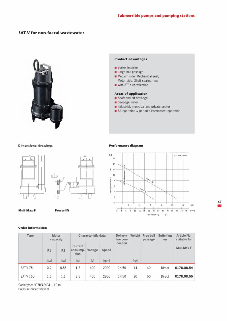
SAT-V for non-faecal wastewater
Product advantages
■ Vortex impeller ■ Large ball passage ■ Medium side: Mechanical seal; Motor side: Shaft sealing ring
■ With ATEX certification
Order information
Submersible pumps and pumping stations
Areas of application ■ Shaft and pit drainage ■ Seepage water ■ Industrial, municipal and private sector ■ S3 operation = periodic intermittent operation
Dimensional drawings Performance diagram
Cable type: H07RN-F4G1 – 10 mPressure outlet: vertical
Type Motorcapacity
Characteristic data Delivery line con-nection
Weight Free ball passage
Switching on
Article No. suitable for
P1 P2Current
consump-tion
Voltage SpeedMuli-Max F
[kW] [kW] [A] [V] [rpm] [kg]
SAT-V 75 0.7 0.55 1.3 400 2900 DN 50 14 40 Direct 0178.08.54
SAT-V 150 1.5 1.1 2.6 400 2900 DN 50 20 50 Direct 0178.08.55
1512963 3027242118
840
2
4
6
8
10
12
14
16
Ges
amtfö
rder
höhe
H
[m]
Förderstrom Q
12
33 45423936 [m³/h]
[l/s]
SAT-V 75
SAT-V 150
2 6 10
n = 2900 U/min
0
Toleranzen ISO 2548/C
Min
dest
förd
erst
rom
DN
50
PowerliftMuli-Max-F
67
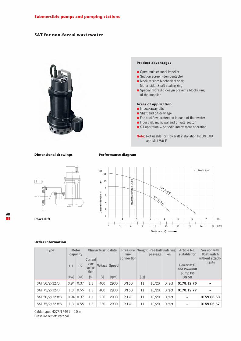
SAT for non-faecal wastewater
Product advantages
■ Open multi-channel impeller ■ Suction screen (demountable) ■ Medium side: Mechanical seal; Motor side: Shaft sealing ring
■ Special hydraulic design prevents blockaging of the impeller
Submersible pumps and pumping stations
Order information
Areas of application ■ In soakaway pits ■ Shaft and pit drainage ■ For backflow protection in case of floodwater ■ Industrial, municipal and private sector ■ S3 operation = periodic intermittent operation
Dimensional drawings Performance diagram
Cable type: H07RN-F4G1 – 10 mPressure outlet: vertical
Note: Not usable for Powerlift installation kit DN 100 and Muli-Max-F
Type Motorcapacity
Characteristic data Pressure line
connection
Weight Free ball passage
Switching on
Article No. suitable for
Version with float switch
without attach-ments
P1 P2
Currentcon-
sump-tion
Voltage Speed Powerlift P and Powerlift
pump kitDN 50[kW] [kW] [A] [V] [rpm] [kg]
SAT 50/2/32/D 0.94 0.37 1.1 400 2900 DN 50 11 10/20 Direct 0178.12.76 –
SAT 75/2/32/D 1.3 0.55 1.3 400 2900 DN 50 11 10/20 Direct 0178.12.77 –
SAT 50/2/32 WS 0.94 0.37 1.1 230 2900 R 1¼" 11 10/20 Direct – 0159.06.63
SAT 75/2/32 WS 1.3 0.55 1.3 230 2900 R 1¼" 11 10/20 Direct – 0159.06.67
63 15129
420
2
4
6
8
10
12
Ges
amtfö
rder
höhe
H
[m]
Förderstrom Q
6
2118 [m³/h]
[l/s]
SAT 50/2/32
1 3 5 7
0 2724
n = 2900 U/min
Toleranzen ISO 2548/C
SAT 75/2/32
Min
dest
förd
erst
rom
DN
50
Powerlift 68
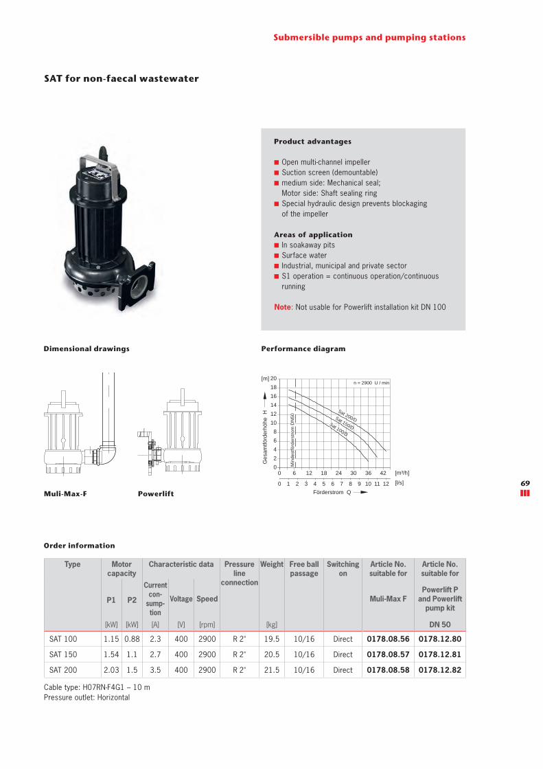
SAT for non-faecal wastewater
Product advantages
■ Open multi-channel impeller ■ Suction screen (demountable) ■ medium side: Mechanical seal; Motor side: Shaft sealing ring
■ Special hydraulic design prevents blockaging of the impeller
Order information
Submersible pumps and pumping stations
Areas of application ■ In soakaway pits ■ Surface water ■ Industrial, municipal and private sector ■ S1 operation = continuous operation/continuous running
Dimensional drawings Performance diagram
Note: Not usable for Powerlift installation kit DN 100
Type Motorcapacity
Characteristic data Pressure line
connection
Weight Free ball passage
Switching on
Article No. suitable for
Article No. suitable for
P1 P2
Currentcon-
sump-tion
Voltage Speed Muli-Max FPowerlift P
and Powerlift pump kit
[kW] [kW] [A] [V] [rpm] [kg] DN 50
SAT 100 1.15 0.88 2.3 400 2900 R 2" 19.5 10/16 Direct 0178.08.56 0178.12.80
SAT 150 1.54 1.1 2.7 400 2900 R 2" 20.5 10/16 Direct 0178.08.57 0178.12.81
SAT 200 2.03 1.5 3.5 400 2900 R 2" 21.5 10/16 Direct 0178.08.58 0178.12.82
Cable type: H07RN-F4G1 – 10 mPressure outlet: Horizontal
Toleranzen ISO 2548 / Cn = 2900 U / min
0
1211109876543210
42363024181260
2468
1816141210
Min
dest
förd
erst
rom
DN
50 Sat 150/D
Sat 200/D Sat 100/D
20
Ges
amtfö
rder
höhe
H
[m]
[m³/h]
[l/s]
Förderstrom QPowerlift Muli-Max-F69
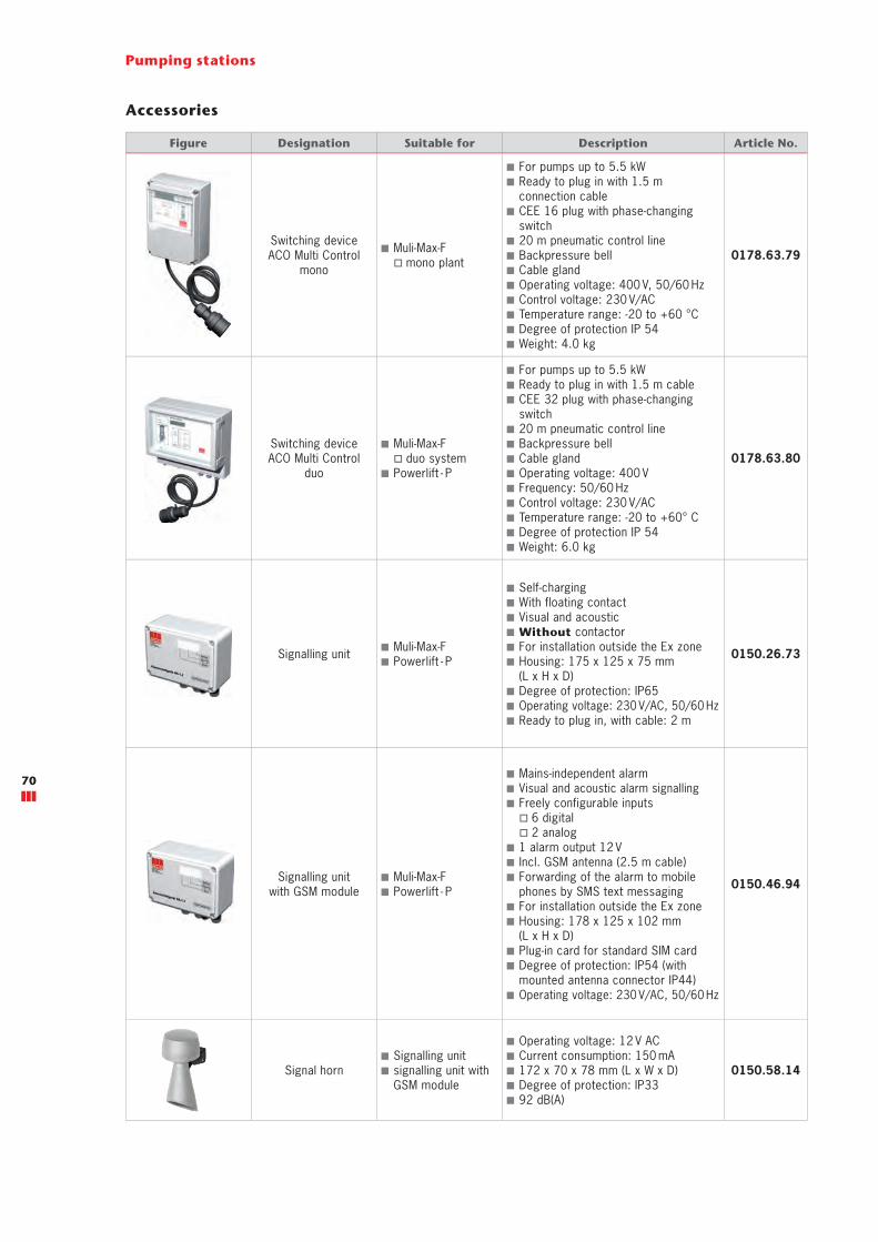
Pumping stations
Accessories
Figure Designation Suitable for Description Article No.
Switching deviceACO Multi Control
mono
■ Muli-Max-F � mono plant
■ For pumps up to 5.5 kW ■ Ready to plug in with 1.5 m connection cable
■ CEE 16 plug with phase-changing switch
■ 20 m pneumatic control line ■ Backpressure bell ■ Cable gland ■ Operating voltage: 400 V, 50/60 Hz ■ Control voltage: 230 V/AC ■ Temperature range: -20 to +60 °C ■ Degree of protection IP 54 ■ Weight: 4.0 kg
0178.63.79
Switching deviceACO Multi Control
duo
■ Muli-Max-F � duo system
■ Powerlift - P
■ For pumps up to 5.5 kW ■ Ready to plug in with 1.5 m cable ■ CEE 32 plug with phase-changing switch
■ 20 m pneumatic control line ■ Backpressure bell ■ Cable gland ■ Operating voltage: 400 V ■ Frequency: 50/60 Hz ■ Control voltage: 230 V/AC ■ Temperature range: -20 to +60° C ■ Degree of protection IP 54 ■ Weight: 6.0 kg
0178.63.80
Signalling unit ■ Muli-Max-F ■ Powerlift - P
■ Self-charging ■ With floating contact ■ Visual and acoustic ■ Without contactor ■ For installation outside the Ex zone ■ Housing: 175 x 125 x 75 mm (L x H x D)
■ Degree of protection: IP65 ■ Operating voltage: 230 V/AC, 50/60 Hz ■ Ready to plug in, with cable: 2 m
0150.26.73
Signalling unit with GSM module
■ Muli-Max-F ■ Powerlift - P
■ Mains-independent alarm ■ Visual and acoustic alarm signalling ■ Freely configurable inputs
� 6 digital � 2 analog
■ 1 alarm output 12 V ■ Incl. GSM antenna (2.5 m cable) ■ Forwarding of the alarm to mobile phones by SMS text messaging
■ For installation outside the Ex zone ■ Housing: 178 x 125 x 102 mm (L x H x D)
■ Plug-in card for standard SIM card ■ Degree of protection: IP54 (with mounted antenna connector IP44)
■ Operating voltage: 230 V/AC, 50/60 Hz
0150.46.94
Signal horn ■ Signalling unit ■ signalling unit with GSM module
■ Operating voltage: 12 V AC ■ Current consumption: 150 mA ■ 172 x 70 x 78 mm (L x W x D) ■ Degree of protection: IP33 ■ 92 dB(A)
0150.58.14
70
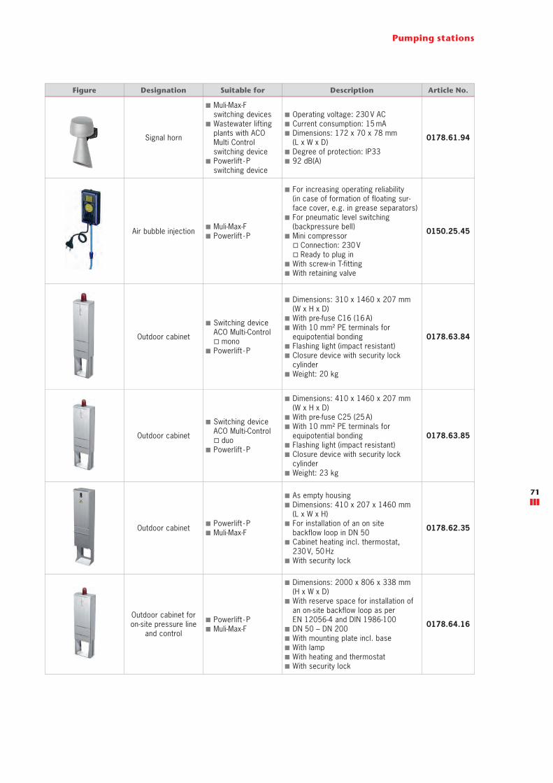
Pumping stations
Figure Designation Suitable for Description Article No.
Signal horn
■ Muli-Max-Fswitching devices
■ Wastewater lifting plants with ACO Multi Control switching device
■ Powerlift - P switching device
■ Operating voltage: 230 V AC ■ Current consumption: 15 mA ■ Dimensions: 172 x 70 x 78 mm (L x W x D)
■ Degree of protection: IP33 ■ 92 dB(A)
0178.61.94
Air bubble injection ■ Muli-Max-F ■ Powerlift - P
■ For increasing operating reliability(in case of formation of floating sur-face cover, e.g. in grease separators)
■ For pneumatic level switching(backpressure bell)
■ Mini compressor � Connection: 230 V � Ready to plug in
■ With screw-in T-fitting ■ With retaining valve
0150.25.45
Outdoor cabinet
■ Switching deviceACO Multi-Control
� mono ■ Powerlift - P
■ Dimensions: 310 x 1460 x 207 mm (W x H x D)
■ With pre-fuse C16 (16 A) ■ With 10 mm² PE terminals forequipotential bonding
■ Flashing light (impact resistant) ■ Closure device with security lock cylinder
■ Weight: 20 kg
0178.63.84
Outdoor cabinet
■ Switching deviceACO Multi-Control
� duo ■ Powerlift - P
■ Dimensions: 410 x 1460 x 207 mm (W x H x D)
■ With pre-fuse C25 (25 A) ■ With 10 mm² PE terminals forequipotential bonding
■ Flashing light (impact resistant) ■ Closure device with security lock cylinder
■ Weight: 23 kg
0178.63.85
Outdoor cabinet ■ Powerlift - P ■ Muli-Max-F
■ As empty housing ■ Dimensions: 410 x 207 x 1460 mm (L x W x H)
■ For installation of an on site backflow loop in DN 50
■ Cabinet heating incl. thermostat, 230 V, 50 Hz
■ With security lock
0178.62.35
Outdoor cabinet for on-site pressure line
and control
■ Powerlift - P ■ Muli-Max-F
■ Dimensions: 2000 x 806 x 338 mm (H x W x D)
■ With reserve space for installation of an on-site backflow loop as per EN 12056-4 and DIN 1986-100
■ DN 50 – DN 200 ■ With mounting plate incl. base ■ With lamp ■ With heating and thermostat ■ With security lock
0178.64.16
71

Pumping stations
Accessories
Figure Designation Suitable for Description Article No.
Outdoor cabinet for on-site pressure line
■ Powerlift ■ Muli-Max-F
■ With reserve space for installationof an on-site backflow loop as per EN 12056-4 and DIN 1986-100
■ With mounting plate incl. base ■ With heating and thermostat ■ With CEE and work socket withearth contact
■ Dimensions: 2000 x 806 x 335 mm (H x W x D)
■ DN 80/100/125/150
0178.64.06
Pressure pick-up
■ ACO Multi-Control switching device
� mono � duo
■ Consumption 4 – 20 mA ■ For reliable switching of cable lengths > 12 m
■ 0 – 200 mbarCable for installation: 20 m
Cable for installation: 40 m
0178.63.88
0178.63.87
Safety barrier ■ Pressure pick-up ■ For separating potentially explosive and safe area
■ Incl. housing0178.63.89
Top section, short ■ Muli-Max-F
� Load class: A 15/B 125
■ For increasing the installation depth ■ Total height: 2000 - 2350 mm ■ Incl. operating key ■ Weight: 22 kg
0178.08.35
Guide strap ■ Top section � 0178.08.35
■ Quantity required � 1 for Muli-Max-F mono
� 2 for Muli-Max-F duo
■ Weight: 3 kg
0178.08.79
Top section, long ■ Muli-Max-F
� Load class: A 15/B 125
■ For increasing the installation depth ■ Total height: 2000 - 3000 mm ■ Incl. operating key ■ Weight: 42 kg
0178.08.36
Guide strap ■ Top section � 0178.08.36
■ Quantity required � 1 for Muli-Max-F mono
� 2 for Muli-Max-F duo
■ Weight: 4 kg
0178.08.80
Flushing connection ■ Muli-Max-F ■ Total height: 430 mm ■ Weight: 5 kg 0178.05.22
72

Pumping stations
Figure Designation Suitable for Description Article No.
Vacuum relief valve ■ Muli-Max-F ■ Only possible in conjunctionwith flushing connection
■ Weight: 1.5 kg0178.09.31
Float switch ■ Submersible pumps
� SAT (non-faecal wastewater)
■ 4 are required! ■ Housing made of plastic, polypropylene material
■ Connection cable: 10 m ■ Degree of protection: IP 68/2 bar ■ Switching capacity: 5 A/250 V ■ Switching angle: 10° ■ Restriction: Not approved for use in potentially explosive atmospheres
0159.12.46
ExtensionGuide pipe
DN 50
■ Powerlift installation kit DN 50
■ Powerlift - P
■ Length: 1 m ■ Material: PVC-U ■ For easy installation of pumps indeep shafts or if using a top section
■ Incl. adapter, guide pipe andthreaded rod
0178.12.78
ExtensionGuide pipe
DN 100
■ Powerlift installation kit DN 100
■ Length: 1 m ■ Material: Stainless steel ■ For easy installation of pumps indeep shafts
■ Incl. adapter, guide pipe and threaded rod
0178.12.79
Compression fitting 63 x 63 mm
■ Powerlift installation kit DN 50
■ Powerlift - P
■ Material: PP ■ PN16 ■ for extending the length of pressure lines with 63 mm diameter
0150.38.38
Compression fitting 63 x 75 mm
■ Powerlift installation kit DN 50
■ Powerlift - P
■ Material: PP ■ PN16 ■ For extending the pressure linediameter from 63 mm to 75 mm
0178.13.09
Compression fitting 63 x 90 mm
■ Powerlift installation kit DN 50
■ Powerlift - P
■ Material: PP ■ PN16 ■ For extending the pressure linediameter from 63 mm to 90 mm
0178.13.10
Installation kit, level measurement retainer
■ Powerlift installation kit
■ For retaining / fixing float switches, backpressure bell, or pressure pick-up
■ Incl. fixing material & glands0178.12.94
Toroidal sealing ring ■ Powerlift installation kit DN 100
■ As supplementary componentfor pressure line DN 80 0159.37.97
73

ACO service advantages
Each project is different, it has its own requirements and chal-lenges. Apart from our products, we also offer you our know-how and services, to develop tailormade solutions together – from the design through to support following completion.
support: Construction adviceand supportTo ensure that no unpleasant surprises occur between the design and implementa-tion of a drainage solu-tion, we advise and assist you for a specific project on your construction site.
train: Information and further trainingIn the ACO Academy we share the know-how of the worldwide ACO Group with architects, design engi-neers, installers and trad-ers, for whom quality is important. We invite you to profit from this.
design: Design and optimisationThe specification and design of drainage solu-tions allows many varia-tions. Yet which concept produces the economically best and technically most reliable solution? We help you to find the right answer.
care: Inspection and maintenanceACO products are designed and produced for a long life. With our after-sales offers we ensure that ACO contin-ues to fulfil your high quality standards for many years.
The http://catalogue.aco-haustechnik.de/en/Home website provides plenty of information on lifting plants and pumping stations so that you can quickly search for something for your clients.
Online catalogueWith the new online catalogue on our website you can easily download dimen-sioned drawings and tender specification texts. Here the product can be chosen by using appropriate selection criteria.
Product finder Simple keyword search and article
number Tender specification texts
(TXT, Datanorm and GAEB) Dimensioned drawings (DXF) Product illustrations Installation and assembly instructions
http://catalogue.aco-haustechnik.de/en/Home
Video
ACO lifting plantshttp://aco.me/hebeanlagen
eServicesWastewater lifting plant designWith the help of the dimensioning tool for wastewater lifting plants you can deter-mine the suitable plant for your special application case. This is done by entering a few parameters under:http://catalogue.aco-haustechnik.de/en/Home/Dimensioning-toolsYou determine the suitable wastewater lifting plant in only three steps
Enter the on site use conditions Select a lifting plant with correspond-
ing usable volume Design and dimensioning of the
pumps Output of the calculated values and
filling in of the PDF form
ACO Building Drainage on the internet
74
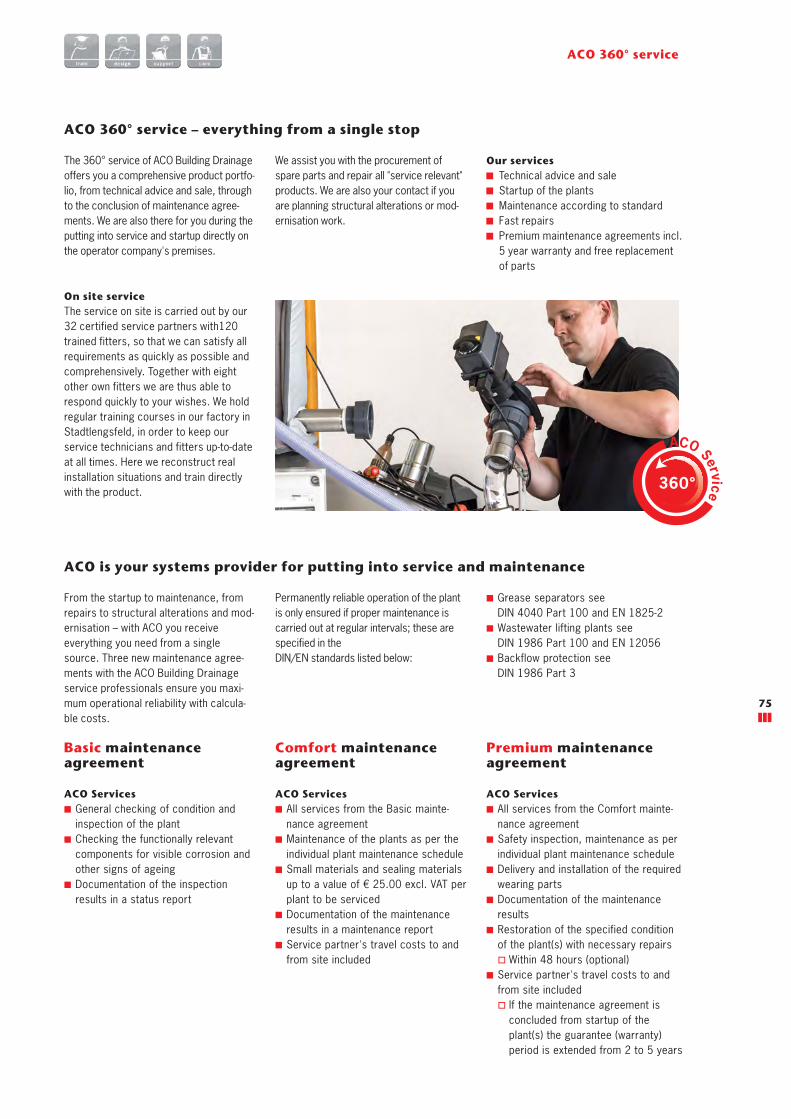
ACO 360° service – everything from a single stop
The 360° service of ACO Building Drainage offers you a comprehensive product portfo-lio, from technical advice and sale, through to the conclusion of maintenance agree-ments. We are also there for you during the putting into service and startup directly on the operator company's premises.
Our services Technical advice and sale Startup of the plants Maintenance according to standard Fast repairs Premium maintenance agreements incl. 5 year warranty and free replacement of parts
ACO 360° service
On site service The service on site is carried out by our 32 certified service partners with120 trained fitters, so that we can satisfy all requirements as quickly as possible and comprehensively. Together with eight other own fitters we are thus able to respond quickly to your wishes. We hold regular training courses in our factory in Stadtlengsfeld, in order to keep our service technicians and fitters up-to-date at all times. Here we reconstruct real installation situations and train directly with the product.
ACO is your systems provider for putting into service and maintenance
From the startup to maintenance, from repairs to structural alterations and mod-ernisation – with ACO you receive everything you need from a single source. Three new maintenance agree-ments with the ACO Building Drainage service professionals ensure you maxi-mum operational reliability with calcula-ble costs.
Permanently reliable operation of the plant is only ensured if proper maintenance is carried out at regular intervals; these are specified in the DIN/EN standards listed below:
ACO Services ■ General checking of condition and inspection of the plant
■ Checking the functionally relevant components for visible corrosion and other signs of ageing
■ Documentation of the inspection results in a status report
Basic maintenance agreement
ACO Services ■ All services from the Basic mainte-nance agreement
■ Maintenance of the plants as per the individual plant maintenance schedule
■ Small materials and sealing materials up to a value of € 25.00 excl. VAT per plant to be serviced
■ Documentation of the maintenance results in a maintenance report
■ Service partner's travel costs to and from site included
Comfort maintenance agreement
ACO Services ■ All services from the Comfort mainte-nance agreement
■ Safety inspection, maintenance as per individual plant maintenance schedule
■ Delivery and installation of the required wearing parts
■ Documentation of the maintenance results
■ Restoration of the specified condition of the plant(s) with necessary repairs
� Within 48 hours (optional) ■ Service partner's travel costs to and from site included
� If the maintenance agreement is concluded from startup of the plant(s) the guarantee (warranty) period is extended from 2 to 5 years
Premium maintenance agreement
ACO Service360°
We assist you with the procurement of spare parts and repair all "service relevant" products. We are also your contact if you are planning structural alterations or mod-ernisation work.
■ Grease separators see DIN 4040 Part 100 and EN 1825-2
■ Wastewater lifting plants see DIN 1986 Part 100 and EN 12056
■ Backflow protection see DIN 1986 Part 3
75
Geb
60
01/2
017
Lor
f Su
bjec
t to
chan
ge w
ithou
t not
ice
ACO Passavant GmbH
Im Gewerbepark 11cD 36457 StadtlengsfeldTel. 036965 819-0Fax 036965 819-361www.aco-haustechnik.de
Each product of ACO Building Drainage supports the ACO system chain
collect
Floor drainage
Bathroom drainage
Roof drainage
Parking deck drainage
Balcony and terracedrainage
Pipe systems
clean
Grease separators
Starch separators
Light liquid separators
Process engineering
hold
Backflow preventers
release
Lifting plants
Pumping stations
ACO. The future of drainage.