acme chemicals - eagle inspection...
TRANSCRIPT

Report No.: 20161.105.54Inspector: Jeff WallingEmployer: Eagle Inspection TechnologiesInspection Date: 9/19/2012
ACME ChemicalsChester, PA
Tank 54
API Certification No. 2071
Sodium Silicate Solution
Inspector Signature
OUT-OF-SERVICE
Inspection Report For
An API Standard 653 out-of-service inspection was completed on Tank #54 at the ACME Chemicals facility located in Chester, PA on 09/19/2012. The inspection was conducted in accordance with client criterion for NDE which included visual and UT examinations. The tank was built to API-12C specification for AST tanks for storing Sodium Silicate Solution. This inspection was conducted in accordance with requirements of the API-653 standards. The following is a detailed report of the inspection including findings and recommendations.
Page 1

3.0 INSPECTION RESULTS3.1 Foundation3.2 Shell3.3 Appurtenances 3.4 Roof3.5 Floor3.6 Ancillary Equipment3.7 Other
4.0 RECOMMENDATIONS4.1 Foundation4.2 Shell4.3 Appurtenances 4.4 Roof4.5 Floor4.6 Ancillary Equipment4.7 Other4.8 Next Inspections
5.0 ULTRASONIC THICKNESS (UT) MEASUREMENTS5.1 Results Summary 5.2 Recommendations
1.0 EXECUTIVE SUMMARY
2.0 VESSEL DATA
TABLE OF CONTENTS
APPENDIX A
APPENDIX B
APPENDIX C
APPENDIX D
APPENDIX E
APPENDICIES Mechanical Integrity Supporting Calculations
Thickness Measurement Record
Inspection Drawings
Inspection Checklist
Inspection Photographs
APPENDIX F Venting Calculations
APPENDIX G NDE Records and Certifications
APPENDIX H References
Page 2
1.0 EXECUTIVE SUMMARY
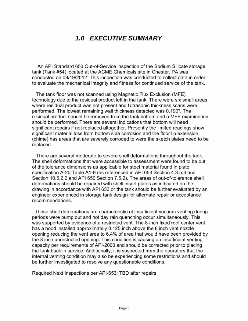
An API Standard 653 Out-of-Service inspection of the Sodium Silicate storage tank (Tank #54) located at the ACME Chemicals site in Chester, PA was conducted on 09/19/2012. This inspection was conducted to collect data in orderto evaluate the mechanical integrity and fitness for continued service of the tank.
The tank floor was not scanned using Magnetic Flux Exclusion (MFE) technology due to the residual product left in the tank. There were six small areas where residual product was not present and Ultrasonic thickness scans were performed. The lowest remaining wall thickness detected was 0.190". The residual product should be removed from the tank bottom and a MFE examination should be performed. There are several indications that bottom will need significant repairs if not replaced altogether. Presently the limited readings show significant material loss from bottom side corrosion and the floor lip extension(chime) has areas that are severely corroded to were the sketch plates need to be replaced.
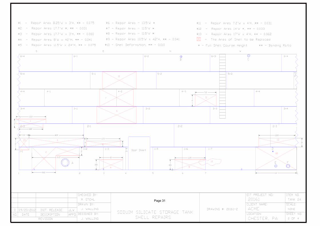
There are several moderate to severe shell deformations throughout the tank. The shell deformations that were accessible to assessment were found to be out of the tolerance dimensions as applicable for steel material found in plate specification A-20 Table A1-9 (as referenced in API 653 Section 4.3.5.3 and Section 10.5.2.2 and API 650 Section 7.5.2). The areas of out-of-tolerance shell deformations should be repaired with shell insert plates as indicated on the drawing in accordance with API 653 or the tank should be further evaluated by an engineer experienced in storage tank design for alternate repair or acceptance recommendations.
These shell deformations are characteristic of insufficient vacuum venting during periods were pump out and hot day rain quenching occur simultaneously. This was supported by evidence of a restricted vent. The 8-inch fixed roof center venthas a hood installed approximately 0.125 inch above the 8 inch vent nozzle opening reducing the vent area to 6.4% of area that would have been provided by the 8 inch unrestricted opening. This condition is causing an insufficient ventingcapacity per requirements of API-2000 and should be corrected prior to placing the tank back in service. Additionally, it is suspected from the operators that the internal venting condition may also be experiencing some restrictions and shouldbe further investigated to resolve any questionable conditions.
Required Next Inspections per API-653: TBD after repairs
Page 3
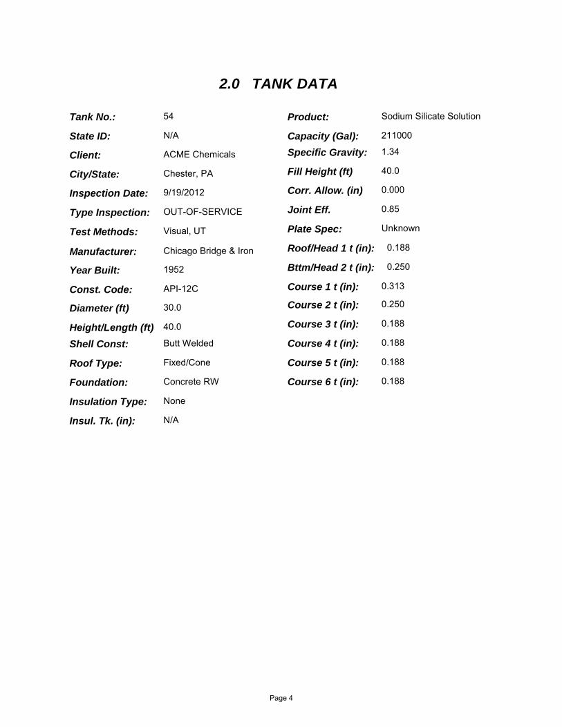
54
Client: ACME Chemicals
N/A
Inspection Date: 9/19/2012
Type Inspection: OUT-OF-SERVICE
Year Built: 1952
Const. Code: API-12C
211000
Test Methods: Visual, UT
Chester, PA
30.0
2.0 TANK DATA
40.0
Shell Const: Butt Welded
Roof Type: Fixed/Cone
Manufacturer: Chicago Bridge & Iron
Foundation: Concrete RW
Specific Gravity: 1.34
Product: Sodium Silicate Solution
0.000
Joint Eff. 0.85
0.250
0.188
0.188
Plate Spec: Unknown
40.0
0.188
0.188
0.313
0.188
0.250
Insulation Type: None
N/A
Diameter (ft)
Height/Length (ft)
Corr. Allow. (in)
Fill Height (ft)
Course 1 t (in):
Course 2 t (in):
Course 3 t (in):
Course 4 t (in):
Course 5 t (in):
Course 6 t (in):
Roof/Head 1 t (in):
Bttm/Head 2 t (in):
Insul. Tk. (in):
Capacity (Gal):State ID:
City/State:
Tank No.:
Page 4
3.1 Foundation:
3.1.1 The foundation is constructed of a concrete Ringwall. Thecontainment structure is designed of concrete and earthen material.
3.1.2 The concrete ringwall foundation has a few hairline cracks throughout the circumference but is in overall satisfactory condition.
3.1.3 There is no tank bottom to foundation sealant and the existingconcrete grout that act as the bearing surface for the shell has deteriorated and is missing in several locations.
3.2 Shell:
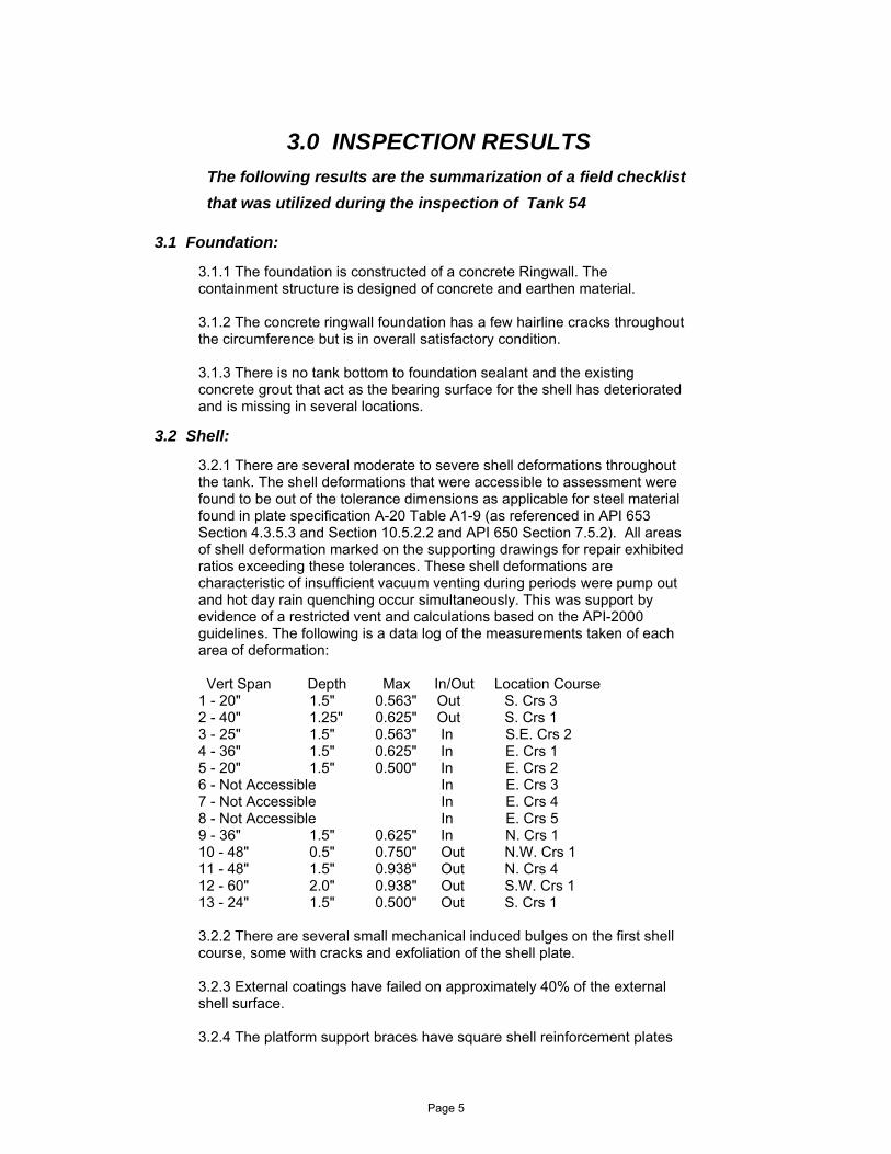
3.2.1 There are several moderate to severe shell deformations throughout the tank. The shell deformations that were accessible to assessment were found to be out of the tolerance dimensions as applicable for steel material found in plate specification A-20 Table A1-9 (as referenced in API 653 Section 4.3.5.3 and Section 10.5.2.2 and API 650 Section 7.5.2). All areas of shell deformation marked on the supporting drawings for repair exhibited ratios exceeding these tolerances. These shell deformations are characteristic of insufficient vacuum venting during periods were pump out and hot day rain quenching occur simultaneously. This was support by evidence of a restricted vent and calculations based on the API-2000 guidelines. The following is a data log of the measurements taken of each area of deformation:
Vert Span Depth Max In/Out Location Course1 - 20" 1.5" 0.563" Out S. Crs 32 - 40" 1.25" 0.625" Out S. Crs 13 - 25" 1.5" 0.563" In S.E. Crs 24 - 36" 1.5" 0.625" In E. Crs 15 - 20" 1.5" 0.500" In E. Crs 26 - Not Accessible In E. Crs 37 - Not Accessible In E. Crs 48 - Not Accessible In E. Crs 59 - 36" 1.5" 0.625" In N. Crs 110 - 48" 0.5" 0.750" Out N.W. Crs 111 - 48" 1.5" 0.938" Out N. Crs 412 - 60" 2.0" 0.938" Out S.W. Crs 113 - 24" 1.5" 0.500" Out S. Crs 1
3.2.2 There are several small mechanical induced bulges on the first shell course, some with cracks and exfoliation of the shell plate.
3.2.3 External coatings have failed on approximately 40% of the externalshell surface.
3.2.4 The platform support braces have square shell reinforcement plates
3.0 INSPECTION RESULTS
The following results are the summarization of a field checklist
that was utilized during the inspection of Tank 54
Page 5
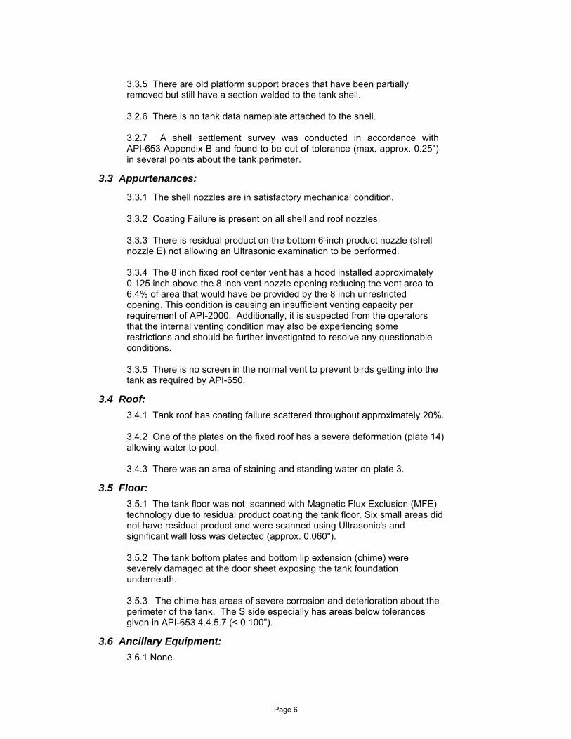
3.3.5 There are old platform support braces that have been partially removed but still have a section welded to the tank shell.
3.2.6 There is no tank data nameplate attached to the shell.
3.2.7 A shell settlement survey was conducted in accordance with API-653 Appendix B and found to be out of tolerance (max. approx. 0.25") in several points about the tank perimeter.
3.3 Appurtenances:
3.3.1 The shell nozzles are in satisfactory mechanical condition.
3.3.2 Coating Failure is present on all shell and roof nozzles.
3.3.3 There is residual product on the bottom 6-inch product nozzle (shell nozzle E) not allowing an Ultrasonic examination to be performed.
3.3.4 The 8 inch fixed roof center vent has a hood installed approximately 0.125 inch above the 8 inch vent nozzle opening reducing the vent area to 6.4% of area that would have be provided by the 8 inch unrestricted opening. This condition is causing an insufficient venting capacity per requirement of API-2000. Additionally, it is suspected from the operators that the internal venting condition may also be experiencing some restrictions and should be further investigated to resolve any questionable conditions.
3.3.5 There is no screen in the normal vent to prevent birds getting into the tank as required by API-650.
3.4 Roof:
3.4.1 Tank roof has coating failure scattered throughout approximately 20%.
3.4.2 One of the plates on the fixed roof has a severe deformation (plate 14) allowing water to pool.
3.4.3 There was an area of staining and standing water on plate 3.
3.5 Floor:
3.5.1 The tank floor was not scanned with Magnetic Flux Exclusion (MFE) technology due to residual product coating the tank floor. Six small areas did not have residual product and were scanned using Ultrasonic's and significant wall loss was detected (approx. 0.060").
3.5.2 The tank bottom plates and bottom lip extension (chime) were severely damaged at the door sheet exposing the tank foundation underneath.
3.5.3 The chime has areas of severe corrosion and deterioration about the perimeter of the tank. The S side especially has areas below tolerances given in API-653 4.4.5.7 (< 0.100").
3.6 Ancillary Equipment:
3.6.1 None.
Page 6

3.7 Other:
3.7.1 The center column was checked for plumb and found to be satisfactory.
3.7.2 The tank was checked for plumbness (limited to three quadrant due to interference of the building structure on the West side) and found to be nominally -2.00" in all three quadrants (top portion of the tank leaning inward from the bottom). The max tolerance in accordance with API-650 7.5.2 is 1/200 = 0.005 Ratio. The plumbness is with-in tolerance.
Bttm Top RatioSouth Q.: 2.75" - 5" = - 2.25" - 0.0046East Q.: 3.50" - 5" = - 1.50" - 0.0031North Q.: 3.25" - 5" = - 1.75" - 0.0037
Plumbness Checks
Page 7

4.1 Foundation:
4.1.1 Seal hairline cracks in ring wall to prevent water ingress and further deterioration from water freezing/expanding and rebar corrosion.
4.1.2 Repair the existing concrete grout between the tank bottom and concrete ringwall foundation. Verify the level plane.
4.2 Shell:
4.2.1 Repair the areas of out-of-tolerance shell deformations with shell insert plates as indicated on the drawing in accordance with API 653 Section 9 or have the tank further evaluated by an engineer experienced in storage tank design for alternate repairs or acceptance.
4.2.2 Repair the areas where the mechanical induced bulges are present in accordance with API 653 Section 9.
4.2.3 Restore all areas of coating failure to restore 100% coverage.
4.2.4 Remove the existing, newly installed platform support, shell reinforcement plates and modify them to have rounded corners to be in compliance with API-653 repair and modification guidelines.
4.2.5 Remove the sections of the old support braces that are welded to the shell. Perform a visual inspection and repair coatings in the areas where the braces were removed.
4.4.6 The out of plane settlement of the shell should be addressed when the grout is repaired to jack up those areas that are out of tolerance about the perimeter of the tank.
4.3 Nozzle:
4.3.1 Repair all areas of failed coating on the shell and roof nozzles to restore 100% coverage.
4.3.2 Remove the residual product from the bottom 6-inch product nozzle (shell nozzle E) to allow an Ultrasonic examination to be performed.
4.3.3 Modify the existing 8 inch center roof vent cap to provide an unrestricted opening for the normal venting conditions in accordance with API-2000 and install a screen about the vent to prevent birds getting into the tank as required by API-650. Additionally, it is suspected from the operators that the internal venting condition may also be experiencing some restrictions and should be further investigated to resolve any questionable conditions.
4.0 RECOMMENDATIONS
4.4 Roof
Page 8

4.4.1 Repair areas of failed coating to restore to 100% coverage.
4.4.2 Monitor the areas of standing water to assure coating failure does not occur.
4.8 Next Inspections:
4.8.1 Next internal inspection is due by: TBD
4.8.3 Next UT inspection is due by: TBD
Shell4.8.4 Governing component limiting life:
4.5 Floor:
4.5.1 Remove all residual product from the tank bottom and perform a MFE examination to fully assess the bottom floor condition and determine repair needs.
4.5.2 Replace the floor sketch plates with the damaged areas of the chime and door sheet on the East side per API-653 Section 9.
4.6 Ancillary Equipment:
4.6.1 None.
4.7 Other:
4.7.1 None.
Plumbness Checks
4.8.2 Next External inspection is due by: TBD
Page 9

5.1 Results Summary:
5.1.1 Except for the floor, UT examination of tank components (shell, roof, and nozzles) were completed on all accessible surfaces and found to be near nominal thicknesses. Random UT results in limited exposed areas of the tank floor show significant wall loss due to underside corrosion.
5.2 Recommendations:
5.2.1 Required Next Inspections per API-653: TBD after repairs
5.0 ULTRASONIC THICKNESS (UT) MEASUREMENTS
Page 10

APPENDIX A
1) AST Shell RL Calculations
2) AST Roof RL Calculations
3) AST Nozzle RL Calculations
4) Shell Settlement Survey Calculations
5) Specification A-20 Table A1-9
6) MSDS
Mechancial Integrity Calculations
Page 11
File No
28
Report No
20161.105.54
Inspector
Jeff Walling
Client
ACME Chemicals
Tank No
54
Date 9/19/2012
200
Tank Shell Minimum Thickness and Remaining Life Calculations
Temp. (°F)
Material
40.0032.0024.0018.0012.006.00
0.10.10.10.10.10.1
0.2UnknownUnknownUnknownUnknownUnknownUnknown
236002360026000260002600026000
30 1.34 0.85G E 40.0
SEtmin =
Where:
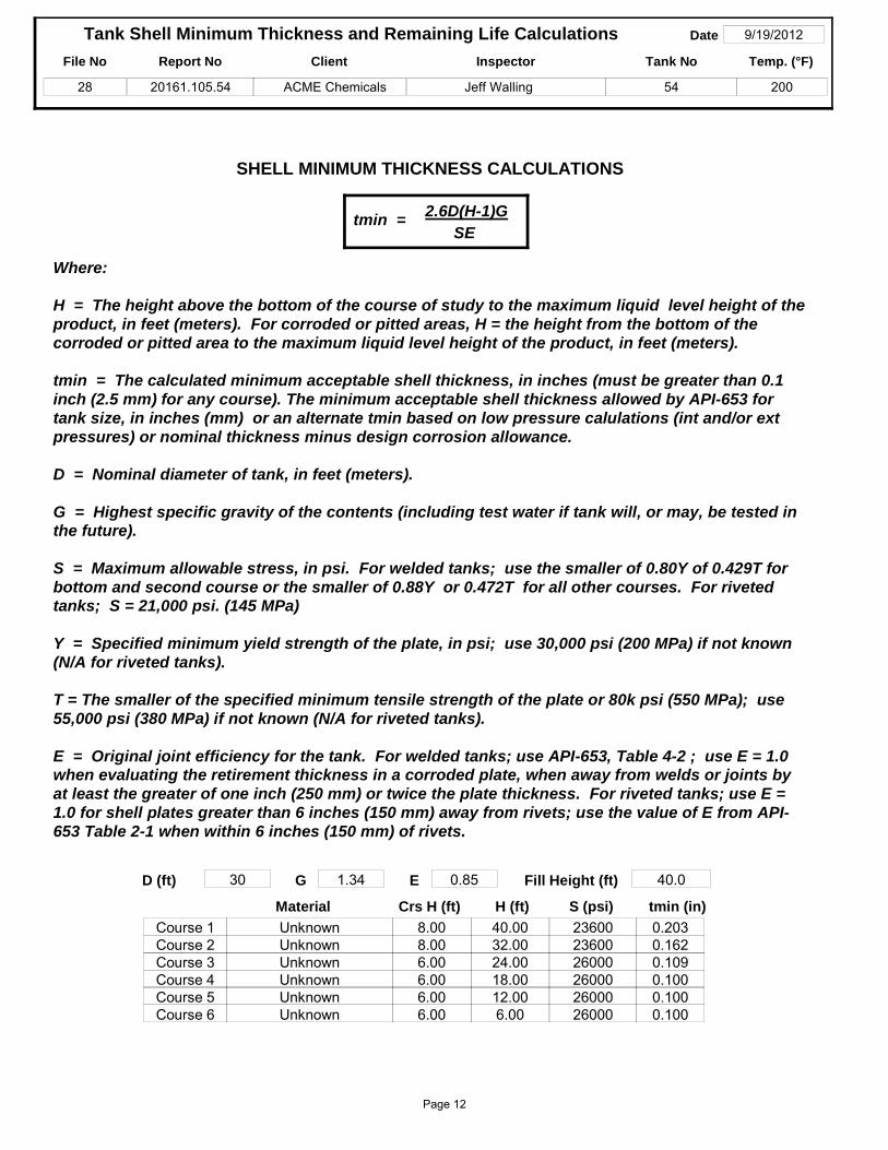
H = The height above the bottom of the course of study to the maximum liquid level height of the product, in feet (meters). For corroded or pitted areas, H = the height from the bottom of the corroded or pitted area to the maximum liquid level height of the product, in feet (meters).
tmin = The calculated minimum acceptable shell thickness, in inches (must be greater than 0.1 inch (2.5 mm) for any course). The minimum acceptable shell thickness allowed by API-653 for tank size, in inches (mm) or an alternate tmin based on low pressure calulations (int and/or ext pressures) or nominal thickness minus design corrosion allowance.
D = Nominal diameter of tank, in feet (meters).
G = Highest specific gravity of the contents (including test water if tank will, or may, be tested in the future).
S = Maximum allowable stress, in psi. For welded tanks; use the smaller of 0.80Y of 0.429T for bottom and second course or the smaller of 0.88Y or 0.472T for all other courses. For riveted tanks; S = 21,000 psi. (145 MPa)
Y = Specified minimum yield strength of the plate, in psi; use 30,000 psi (200 MPa) if not known (N/A for riveted tanks).
T = The smaller of the specified minimum tensile strength of the plate or 80k psi (550 MPa); use 55,000 psi (380 MPa) if not known (N/A for riveted tanks).
E = Original joint efficiency for the tank. For welded tanks; use API-653, Table 4-2 ; use E = 1.0 when evaluating the retirement thickness in a corroded plate, when away from welds or joints by at least the greater of one inch (250 mm) or twice the plate thickness. For riveted tanks; use E = 1.0 for shell plates greater than 6 inches (150 mm) away from rivets; use the value of E from API-653 Table 2-1 when within 6 inches (150 mm) of rivets.
8.008.006.006.006.006.00
Course 1Course 2Course 3Course 4Course 5Course 6
0.1620.1090.1000.1000.100
0.203
SHELL MINIMUM THICKNESS CALCULATIONS
2.6D(H-1)G
tmin (in)S (psi)H (ft)Crs H (ft)
Fill Height (ft)D (ft)
Page 12

File No
28
Report No
20161.105.54
Inspector
Jeff Walling
Client
ACME Chemicals
Tank No
54
Date 9/19/2012
200
Tank Shell Minimum Thickness and Remaining Life Calculations
Temp. (°F)
tmin
0.1620.1090.1000.1000.100
0.2030.2990.2420.1770.1960.1920.188
tact
0.3130.2500.1880.1880.1880.188
tprev Ca
0.0800.0680.0960.0920.088
0.096Cr
0.0002RL
425.80.00010.00020.00000.00000.0000
603.6372.1>40>40>40
Where:
Ca = Remaining corrosion allowance of the shell course under consideration, in inches (mm).
Cr = Corrosion rate of the shell course under consideration, in inches (mm) per year.
FHc = Calculated Fill Height = SEtact/2.6DG+1 (SEtact/4.6DG+.3) plus the total product height below the course of study, in feet (meters).
tact = Minimum thickness measurement of the shell course under consideration, as recorded at the time of inspection, in inches (mm).
tmin = minimum required thickness of shell course, at the maximum allowable fill height, in inches (mm)
tprev = previous thickness measurement of shell course under consideration, as recorded at last inspection or nominal thickness if no previous thickness measurements, in inches (mm).
RL = Estimated remaining life of the shell course under consideration, in years.
Y = Time span between thickness readings or age of the tank if nominal thickness is used for tprev, in years.
SHELL REMAINING LIFE CALCULATIONS
Ca = tact-tmin = Remaining Corrosion Allowance (inches (mm))
Cr = tprev-tact / Y = Corrosion Rate (inches (mm) per year)
RL = Ca / Cr = Remaining Life (years)
60Y = = Tank age (years)
Course 1Course 2Course 3Course 4Course 5Course 6
Course FHc
58.3955.4554.4364.4469.6074.75
Page 13

MINIMUM THICKNESS, REMAINING LIFE, PRESSURE CALCULATIONS
API-653 ATMOSPHERIC STORAGE TANK FIXED ROOF EVALUATION
File No
28Report No
20161.105.54Inspector
Jeff WallingClient
ACME ChemicalsTank No
54
Date
9/19/2012
200DCa
0
Units
U.S.
Temp. °F
Where;Ca = remaining corrosion allowance of the tank component under consideration, in inches (mm) (t act - t min).Cr = corrosion rate of the tank component under consideration, in inches (mm) per year (t prev - t act / Y).DCa = original design corrosion allowance of the tank component under consideration, in inches (mm) KPa = kilopascal - (1 KPa = 1000 Pa) (1 KPa=0.146psi) unit of pressure. It is a measure of force per unit area. 1 pascal (Pa) = 1 N/m2 = 1 J/m3 = 1 kg/(m·s2)oz = unit of measurement, (weight, in ounces, per square inch), (16 oz per pound)psi = unit of measurement, (weight, in pounds, per square inch)RL = estimated remaining life of the tank component under consideration, in years (Ca / Cr). t act = actual thickness measurement of the tank component under consideration, as recorded at the time of inspection, in inches (mm).t min = minimum required thickness of tank component, at the design MAWP at the design temperature (200°F for atm AST's), in inches (mm) (greater of psi/wt or 0.090" (2.3mm). Where tmin calculates to greater than tprev, tprev - 0.063" (1.6mm)).t nom = design nominal thickness of tank component under consideration, in inches (mm).t prev = previous thickness measurement of the tank component under consideration, as recorded at last inspection or nominal thickness if no previous thickness measurements, in inches (mm).t yn = thickness of the tank component under consideration at the next inspection at twice the calculated corrosion rate, in inches (mm) (t act - (2*Cr*Yn).wt = weight of plate per cubic inch.wc = unit of measurement, (height, in inches, of water column bearing on 1 square inch area), (27.7 wc per pound) Y = time span between thickness readings or age of the tank component if tnom is used for tprev, in years.Yn = estimated time span to next inspection of the tank component under consideration, in years
Y
60t prev
0.188t act
0.170t min
0.090Cr
0.00030RL
267
psi
0.047Yn
5
ROOF PLATES - REMAINING LIFE
ROOF MAXIMUM ALLOWABLE INTERNAL PRESSURE
Ca
0.080
0.2833wc
1.31oz.
0.757t yn
0.167
Relief setting is satisfactory
Setting
0.00
RELIEF VALVE SETTING EVALUATIONMax Allowed for weightof plates at next Inspection0.757
Unit
OZ(psi)0.000=
Material Catagory
CS/Crom. Stl
OZ
KPa
0.326wt (psi)
Page 14
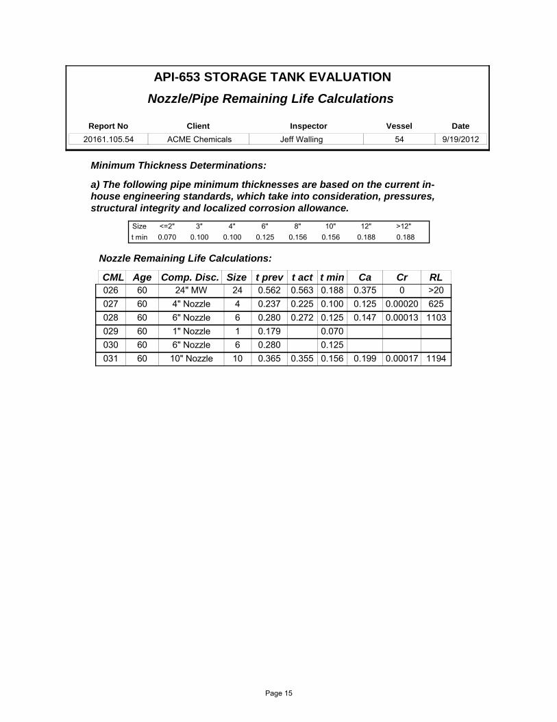
Nozzle/Pipe Remaining Life Calculations
Minimum Thickness Determinations:
a) The following pipe minimum thicknesses are based on the current in-house engineering standards, which take into consideration, pressures, structural integrity and localized corrosion allowance.
Size <=2" 3" 4" 6" 8" 10" 12" >12" t min
API-653 STORAGE TANK EVALUATION
0.070 0.100 0.100 0.125 0.156 0.156 0.188 0.188
Report No
20161.105.54Inspector
Jeff WallingClient
ACME ChemicalsVessel
54Date
9/19/2012
Size t prev t act t min Ca Cr RL
Nozzle Remaining Life Calculations:
CML Comp. Disc.Age24" MW 0.562 0.563 0.188 0.375 0 >20026 2460
4" Nozzle 0.237 0.225 0.100 0.125 0.00020 625027 4606" Nozzle 0.280 0.272 0.125 0.147 0.00013 1103028 6601" Nozzle 0.179 0.070029 1606" Nozzle 0.280 0.125030 66010" Nozzle 0.365 0.355 0.156 0.199 0.00017 1194031 1060
Page 15

API-653 APPENDIX B SHELL SETTLEMENT EVALUATION
Report No
20161.105.54Inspector
JWClient
ACMEVessel
54Date
9/19/2012
R^2 = 0.8335.100
Max Elev
5.190
61.200 62.280
FT
IN 1.080
0.090
Δ ElevBase Elev
(para. B.2.2.4)
API‐653 Shell Settlement Survey
5.04
5.06
5.08
5.10
5.12
5.14
5.16
5.18
5.20
1 2 3 4 5 6 7 8
Settlement Points
Elevation (FT)
Elevation PE
Page 16
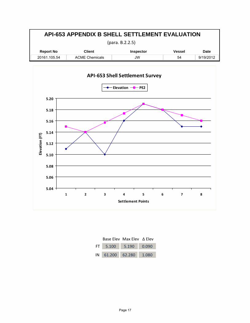
API-653 APPENDIX B SHELL SETTLEMENT EVALUATION
Report No
20161.105.54Inspector
JWClient
ACME ChemicalsVessel
54Date
9/19/2012
5.100
Max Elev
5.190
61.200 62.280
FT
IN 1.080
0.090
Δ ElevBase Elev
(para. B.2.2.5)
API‐653 Shell Settlement Survey
5.04
5.06
5.08
5.10
5.12
5.14
5.16
5.18
5.20
1 2 3 4 5 6 7 8
Settlement Points
Elevation (FT)
Elevation PE2
Page 17
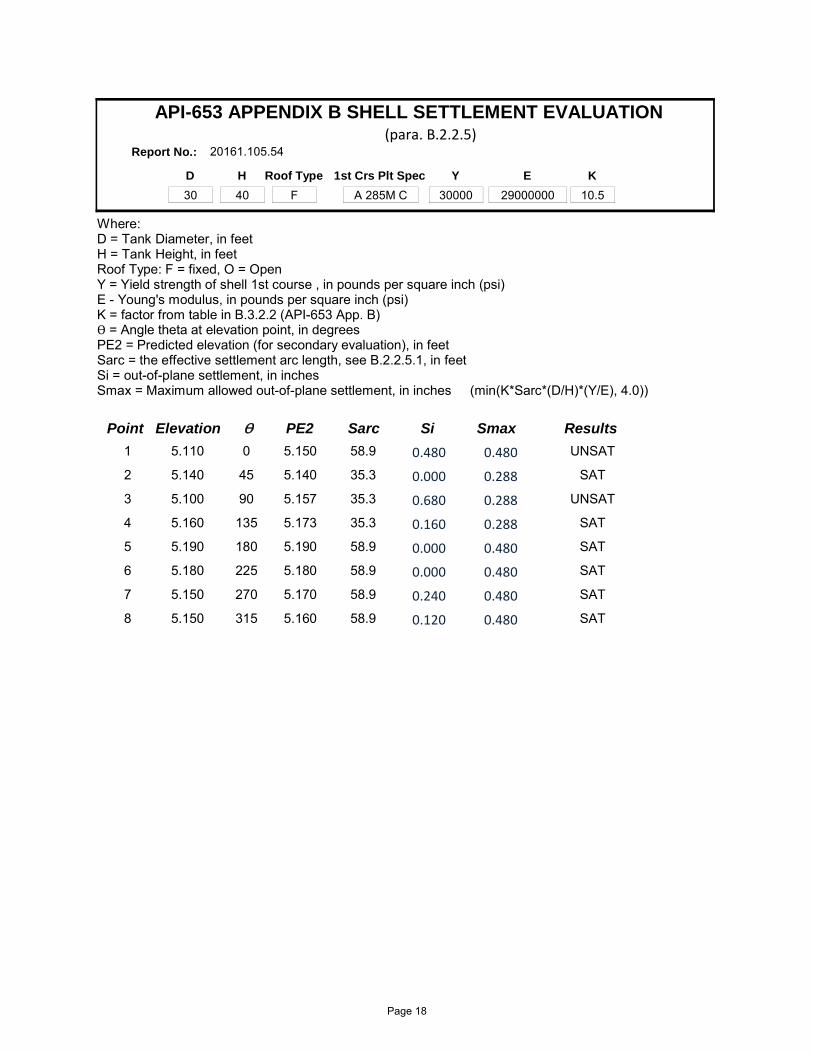
D
30H
40Roof Type
F1st Crs Plt Spec
A 285M CY
30000E
29000000
Where:D = Tank Diameter, in feet H = Tank Height, in feet Roof Type: F = fixed, O = OpenY = Yield strength of shell 1st course , in pounds per square inch (psi)E - Young's modulus, in pounds per square inch (psi)K = factor from table in B.3.2.2 (API-653 App. B)Ө = Angle theta at elevation point, in degreesPE2 = Predicted elevation (for secondary evaluation), in feetSarc = the effective settlement arc length, see B.2.2.5.1, in feetSi = out-of-plane settlement, in inches Smax = Maximum allowed out-of-plane settlement, in inches (min(K*Sarc*(D/H)*(Y/E), 4.0))
API-653 APPENDIX B SHELL SETTLEMENT EVALUATION
Report No.: 20161.105.54(para. B.2.2.5)
10.5K
Ө PE2Elevation Si ResultsPoint SmaxSarc
0 5.1505.110 UNSAT1 0.4800.48058.9
45 5.1405.140 SAT2 0.2880.00035.3
90 5.1575.100 UNSAT3 0.2880.68035.3
135 5.1735.160 SAT4 0.2880.16035.3
180 5.1905.190 SAT5 0.4800.00058.9
225 5.1805.180 SAT6 0.4800.00058.9
270 5.1705.150 SAT7 0.4800.24058.9
315 5.1605.150 SAT8 0.4800.12058.9
Page 18

PART A — FERROUS MATERIAL SPECIFICATIONS SA-20/SA-20M
TA
BL
EA
1.9
98
PE
RM
ISS
IBL
EV
AR
IAT
ION
SF
RO
MF
LA
TN
ES
SF
OR
CA
RB
ON
-ST
EE
LP
LA
TE
S
Var
iati
ons
from
aF
lat
Sur
face
for
Spe
cifi
edW
idth
s,in
.
Ove
r8
Spe
cifi
edto
36,
36to
48,
48to
60,
60to
72,
72to
84,
84to
96,
96to
108,
108
to12
0,12
0to
144,
144
to16
8,16
8an
dT
hick
ness
,in
.ex
clex
clex
clex
clex
clex
clex
clex
clex
clex
clov
er
To
1⁄ 4
,ex
cl9⁄ 1
63⁄ 4
15⁄ 1
61
1⁄ 4
13⁄ 8
11⁄ 2
15⁄ 8
13⁄ 4
17⁄ 8
...
...
1⁄ 4
to3⁄ 8
,ex
cl1⁄ 2
5⁄ 8
3⁄ 4
15⁄ 1
61
1⁄ 8
11⁄ 4
13⁄ 8
11⁄ 2
15⁄ 8
...
...
3⁄ 8
to1⁄ 2
,ex
cl1⁄ 2
9⁄ 1
65⁄ 8
5⁄ 8
3⁄ 4
7⁄ 8
11
1⁄ 8
11⁄ 4
17⁄ 8
21⁄ 8
1⁄ 2
to3⁄ 4
,ex
cl7⁄ 1
61⁄ 2
9⁄ 1
65⁄ 8
5⁄ 8
3⁄ 4
11
11⁄ 8
11⁄ 2
23⁄ 4
to1
,ex
cl7⁄ 1
61⁄ 2
9⁄ 1
65⁄ 8
5⁄ 8
5⁄ 8
3⁄ 4
7⁄ 8
11
3⁄ 8
13⁄ 4
1to
2,
excl
3⁄ 8
1⁄ 2
1⁄ 2
9⁄ 1
69⁄ 1
65⁄ 8
5⁄ 8
5⁄ 8
11⁄ 1
61
1⁄ 8
11⁄ 2
2to
4,
excl
5⁄ 1
63⁄ 8
7⁄ 1
61⁄ 2
1⁄ 2
1⁄ 2
1⁄ 2
9⁄ 1
65⁄ 8
7⁄ 8
11⁄ 8
4to
6,
excl
3⁄ 8
7⁄ 1
61⁄ 2
1⁄ 2
9⁄ 1
69⁄ 1
65⁄ 8
3⁄ 4
7⁄ 8
7⁄ 8
16
to8
,ex
cl7⁄ 1
61⁄ 2
1⁄ 2
5⁄ 8
11⁄ 1
63⁄ 4
7⁄ 8
7⁄ 8
11
18
to1
0,
excl
1⁄ 2
1⁄ 2
5⁄ 8
11⁄ 1
63⁄ 4
13⁄ 1
67⁄ 8
15⁄ 1
61
11
10
to1
2,
excl
1⁄ 2
5⁄ 8
3⁄ 4
13⁄ 1
67⁄ 8
15⁄ 1
61
11
11
12
to1
5,
incl
5⁄ 8
3⁄ 4
13⁄ 1
67⁄ 8
15⁄ 1
61
11
11
...
GE
NE
RA
LN
OT
ES
:(A
)F
latn
ess
Var
iati
ons
for
Len
gth
—T
helo
nger
dim
ensi
onsp
ecif
ied
isco
nsid
ered
the
leng
th,
and
vari
atio
nin
flat
ness
alon
gth
ele
ngth
shal
lno
tex
ceed
the
tabu
lar
amou
ntfo
rth
esp
eci-
fied
wid
thin
plat
esup
to1
2ft
inle
ngth
,or
inan
y1
2ft
oflo
nger
plat
es.
(B)
Fla
tnes
sV
aria
tion
sfo
rW
idth
—T
hefl
atne
ssva
riat
ion
acro
ssth
ew
idth
shal
lno
tex
ceed
the
tabu
lar
amou
ntfo
rth
esp
ecif
ied
wid
th.
(C)
Whe
nth
elo
nger
dim
ensi
onis
unde
r3
6in
.,th
eva
riat
ion
infl
atne
ssal
ong
the
leng
than
dac
ross
the
wid
thsh
all
not
exce
ed1⁄ 4
in.
inea
chdi
rect
ion.
Whe
nth
elo
nger
dim
ensi
onis
from
36
to7
2in
.,in
clus
ive,
the
flat
ness
vari
atio
nsh
all
not
exce
ed7
5%
ofth
eta
bula
ram
ount
for
the
spec
ifie
dw
idth
,bu
tin
noca
sele
ssth
an1⁄ 4
in.
(D)
The
tole
ranc
esgi
ven
inth
ista
ble
appl
yto
plat
esth
atha
vea
min
imum
spec
ifie
dte
nsil
est
reng
thno
tov
er6
00
00
psi
orco
mpa
tibl
ech
emis
try
orha
rdne
ss.
For
plat
essp
ecif
ied
toa
high
erm
inim
umte
nsil
est
reng
thor
com
pati
ble
chem
istr
yor
hard
ness
,th
eli
mit
sgi
ven
inth
eta
ble
are
incr
ease
dto
11⁄ 2
tim
esth
eam
ount
sin
the
abov
eta
ble.
(E)
Thi
sta
ble
and
note
sco
ver
the
flat
ness
tole
ranc
esof
circ
ular
and
sket
chpl
ates
,ba
sed
onth
em
axim
umdi
men
sion
sof
thos
epl
ates
.
85
Page 19

MATERIAL SAFETY DATA SHEET
Trade Name: WRG™ Sodium Silicate Solution Date Prepared: 6/20/2012 Page: 1 of 5
1. CHEMICAL PRODUCT AND COMPANY IDENTIFICATION
Product name: WRG™ Sodium silicate solution Product description: A 3.25 weight ratio sodium silicate, 32.5% solution in water Manufacturer: PQ Corporation P. O. Box 840 Valley Forge, PA USA Phone number: 610-651-4200 Fax number: 610-651-4504 In case of emergency call: 1 610-651-4200 For transportation emergency Call CHEMTREC: 1 800-424-9300
2. COMPOSITION/INFORMATION ON INGREDIENTS
Chemical and Common Name CAS Registry Number Wt. % OSHA PEL ACGIH TLV Water 7732-18-5 67.5% Not Established Not Established Silicic acid, sodium salt; Sodium silicate
1344-09-8 32.5% Not Established Not Established
3. HAZARDS IDENTIFICATION
Emergency Overview: Clear to hazy, colorless, odorless, thick liquid. Causes moderate eye, skin, and digestive tract irritation. Spray mist causes irritation to respiratory tract. High pH is harmful to aquatic life. Noncombustible. Spills are slippery. Reacts with acids, ammonium salts, reactive metals and some organics.
Eye contact: Causes moderate irritation to the eyes. Skin contact: Causes moderate irritation to the skin. Inhalation: Spray mist irritating to respiratory tract. Ingestion: May cause irritation to mouth, esophagus, and stomach. Chronic hazards: No known chronic hazards. Not listed by NTP, IARC or OSHA
as a carcinogen. Physical hazards: Dries to form glass film which can easily cut skin. Spilled
material is very slippery. Can etch glass if not promptly removed.
4. FIRST AID MEASURES
Eye: In case of contact, immediately flush eyes with plenty of water for at least 15 minutes. Get medical attention.
Skin: In case of contact, immediately flush skin with plenty of water. Remove contaminated clothing and shoes. Get medical attention.
MSDS
Page 20

Inhalation: Remove to fresh air. If not breathing, give artificial respiration. If breathing is difficult, give oxygen. Get medical attention.
Ingestion: If swallowed, DO NOT induce vomiting. Get medical attention immediately. If victim is fully conscious, give a cupful of water. Never give anything by mouth to an unconscious person.
5. FIRE FIGHTING MEASURES
Flammable limits: This material is noncombustible. Extinguishing Media: This material is compatible with all extinguishing media. Hazards to fire-fighters: See Section 3 for information on hazards when this material
is present in the area of a fire. Fire-fighting equipment: The following protective equipment for fire fighters is
recommended when this material is present in the area of a fire: chemical goggles, body-covering protective clothing, chemical resistant gloves, and rubber boots.
6. ACCIDENTAL RELEASE MEASURES
Personal protection: Wear chemical goggles, body-covering protective clothing, chemical resistant gloves, and rubber boots. See section 8.
Environmental Hazards: Sinks and mixes with water. High pH of this material is harmful to aquatic life, see Section 12. Only water will evaporate from a spill of this material.
Small spill cleanup: Mop up and neutralize liquid, then discharge to sewer in accordance with federal, state and local regulations or permits.
Large spill cleanup: Keep unnecessary people away; isolate hazard area and deny entry. Do not touch or walk through spilled material. Stop leak if you can do so without risk. Prevent runoff from entering into storm sewers and ditches which lead to natural waterways. Isolate, dike and store discharged material, if possible. Use sand or earth to contain spilled material. If containment is impossible, neutralize contaminated area and flush with large quantities of water.
CERCLA RQ: There is no CERCLA Reportable Quantity for this material. If a spill goes off site, notification of state and local authorities is recommended.
7. HANDLING AND STORAGE
Handling: Avoid contact with eyes, skin and clothing. Avoid breathing spray mist. Keep container closed. Promptly clean residue from closures with cloth dampened with water. Promptly clean up spills.
Storage: Keep containers closed. Store in clean steel or plastic containers. Separate from acids, reactive metals, and ammonium salts. Storage temperature 0-95º C. Loading temperature 45-95 º C. Do not store in aluminum, fiberglass, copper, brass, zinc or galvanized containers.
8. EXPOSURE CONTROLS/PERSONAL PROTECTION
Page 21
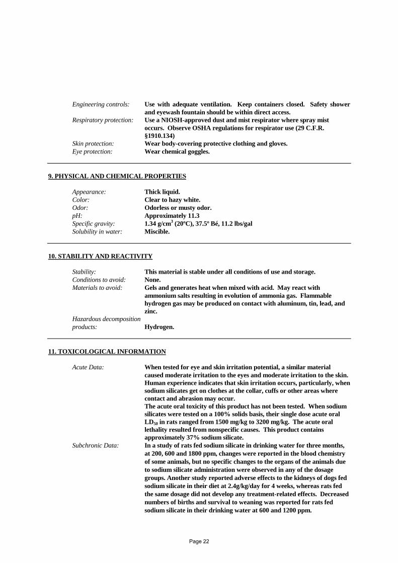
Engineering controls: Use with adequate ventilation. Keep containers closed. Safety shower and eyewash fountain should be within direct access.
Respiratory protection: Use a NIOSH-approved dust and mist respirator where spray mist occurs. Observe OSHA regulations for respirator use (29 C.F.R. §1910.134)
Skin protection: Wear body-covering protective clothing and gloves. Eye protection: Wear chemical goggles.
9. PHYSICAL AND CHEMICAL PROPERTIES Appearance: Thick liquid. Color: Clear to hazy white.
Odor: Odorless or musty odor. pH: Approximately 11.3 Specific gravity: 1.34 g/cm3 (20ºC), 37.5º Bé, 11.2 lbs/gal Solubility in water: Miscible. 10. STABILITY AND REACTIVITY
Stability: This material is stable under all conditions of use and storage. Conditions to avoid: None. Materials to avoid: Gels and generates heat when mixed with acid. May react with
ammonium salts resulting in evolution of ammonia gas. Flammable hydrogen gas may be produced on contact with aluminum, tin, lead, and zinc.
Hazardous decomposition products: Hydrogen. 11. TOXICOLOGICAL INFORMATION
Acute Data: When tested for eye and skin irritation potential, a similar material caused moderate irritation to the eyes and moderate irritation to the skin. Human experience indicates that skin irritation occurs, particularly, when sodium silicates get on clothes at the collar, cuffs or other areas where contact and abrasion may occur.
The acute oral toxicity of this product has not been tested. When sodium silicates were tested on a 100% solids basis, their single dose acute oral LD50 in rats ranged from 1500 mg/kg to 3200 mg/kg. The acute oral lethality resulted from nonspecific causes. This product contains approximately 37% sodium silicate.
Subchronic Data: In a study of rats fed sodium silicate in drinking water for three months, at 200, 600 and 1800 ppm, changes were reported in the blood chemistry of some animals, but no specific changes to the organs of the animals due to sodium silicate administration were observed in any of the dosage groups. Another study reported adverse effects to the kidneys of dogs fed sodium silicate in their diet at 2.4g/kg/day for 4 weeks, whereas rats fed the same dosage did not develop any treatment-related effects. Decreased numbers of births and survival to weaning was reported for rats fed sodium silicate in their drinking water at 600 and 1200 ppm.
Page 22

Special Studies: Sodium silicate was not mutagenic to the bacterium E. Coli when tested in a mutagenicity bioassay. There are no known reports of carcinogenicity of sodium silicates. Frequent ingestion over extended periods of time of gram quantities of silicates is associated with the formation kidney stones and other siliceous urinary calculi in humans. Sodium silicate is not listed by IARC, NTP or OSHA as a carcinogen.
12. ECOLOGICAL INFORMATION
Eco toxicity: The following data is reported for sodium silicates on a 100% solids basis: A 96 hour median tolerance for fish (Gambusia affnis) of 2320 ppm; a 96 hour median tolerance for water fleas (Daphnia magna) of 247 ppm; a 96 hour median tolerance for snail eggs (Lymnea) of 632 ppm; and a 96 hour median tolerance for Amphipoda of 160 ppm. This product contains approximately 37% sodium silicate.
Environmental Fate: This material is not persistent in aquatic systems, but its high pH when undiluted or unneutralized is acutely harmful to aquatic life. Diluted material rapidly depolymerizes to yield dissolved silica in a form that is indistinguishable from natural dissolved silica. It does not contribute to BOD. This material does not bioaccumulate except in species that use silica as a structural material such as diatoms and siliceous sponges. Where abnormally low natural silica concentrations exist (less than 0.1 ppm), dissolved silica may be a limiting nutrient for diatoms and a few other aquatic algal species. However, the addition of excess dissolved silica over the limiting concentration will not stimulate the growth of diatom populations; their growth rate is independent of silica concentration once the limiting concentration is exceeded. Neither silica nor sodium will appreciably bioconcentrate up the food chain.
Physical/Chemical: Sinks and mixes with water. Only water will evaporate from this material. 13. DISPOSAL CONSIDERATIONS
Classification: Disposed material is not a hazardous waste. Disposal Method: Dispose in accordance with federal, state and local regulations and
permits.
Page 23

14. TRANSPORT INFORMATION DOT UN Status: This material is not regulated hazardous material for transportation. 15. REGULATORY INFORMATION
CERCLA: No CERCLA Reportable Quantity has been established for this material. SARA TITLE III: Not an Extremely Hazardous Substance under §302. Not a Toxic
Chemical under §313. Hazard Categories under §§311/312: Acute TSCA: All ingredients of this material are listed on the TSCA inventory. FDA: The use of sodium silicate is authorized by FDA as a boiler water additive
for the production of steam that will contact food pursuant to 21 CFR §173.310; as a component of zinc-silicon dioxide matrix coatings on food contact surfaces pursuant to 21 CFR §175.390(c); as a GRAS substance when migrating from cotton fabric used in dry food packaging pursuant to 21 CFR §182.70; and as a GRAS substance when migrating to food from paper and paperboard products pursuant to 21 CFR §182.90.
16. OTHER INFORMATION
Prepared by: HSE Dept. / Erin A. Bendig Supersedes revision of: 3/18/2005
THE INFORMATION ON THIS SAFETY DATA SHEET IS BELIEVED TO BE ACCURATE AND IT IS THE BEST
INFORMATION AVAILABLE TO PQ CORPORATION THIS DOCUMENT IS INTENDED ONLY AS A GUIDE TO THE
APPROPRIATE PRECAUTIONS FOR HANDLING A CHEMICAL BY A PERSON TRAINED IN CHEMICAL HANDLING. PQ CORPORATION MAKES NO WARRANTY OF MERCHANTABILITY OR ANY OTHER WARRANTY, EXPRESS OR
IMPLIED WITH RESPECT TO SUCH INFORMATION OR THE PRODUCT TO WHICH IT RELATES, AND WE ASSUME
NO LIABILITY RESULTING FROM THE USE OR HANDLING OF THE PRODUCT TO WHICH THIS SAFETY DATA
SHEET RELATES. USERS AND HANDLERS OF THIS PRODUCT SHOULD MAKE THEIR OWN INVESTIGATIONS TO
DETERMINE THE SUITABILITY OF THE INFORMATION PROVIDED HEREIN FOR THEIR OWN PURPOSES.
Page 24

APPENDIX B
1) Shell UT Measurments
2) Roof UT Measurments
3) Floor UT Measurments
4) Nozzle UT Measurments
Thickness Measurement Record
Page 25

AST Component Inspection Data
Component Thickness Measurements (in inches)
API-653 STORAGE TANK EVALUATION
Report No
20161.105.54Inspector
Jeff WallingClient
ACME ChemicalsVessel
54Date
9/19/2012
Location tml-1 tml-2 tml-3 tml-4 MinimumComponent tml-5CML tml-6
Chime Plt 1 0.311 0.310 0.311 0.314 0.310Shell Crs 1 0.319001 0.319
Chime Plt 2 0.313 0.318 0.318 0.316 0.307Shell Crs 1 0.314002 0.307
Chime Plt 3 0.319 0.318 0.317 0.317 0.315Shell Crs 1 0.318003 0.315
Chime Plt 4 0.309 0.315 0.309Shell Crs 1004
Chime Plt 5 0.314 0.313 0.321 0.319 0.313Shell Crs 1 0.317005 0.314
Chime Plt 6 0.309 0.306 0.302 0.306 0.302Shell Crs 1 0.306006 0.305
Chime Plt 7 0.309 0.305 0.310 0.309 0.305Shell Crs 1 0.321007 0.310
Drop # 1 0.312 0.310 0.307 0.307Shell Crs 1008
Drop # 1 0.250 0.254 0.255 0.250Shell Crs 2009
Drop # 1 0.194 0.200 0.196 0.194Shell Crs 3010
Drop # 1 0.205 0.202 0.196 0.196Shell Crs 4011
Drop # 1 0.197 0.197 0.192 0.192Shell Crs 5012
Drop # 1 0.192 0.188 0.196 0.188Shell Crs 6013
Drop # 2 0.299 0.303 0.305 0.299Shell Crs 1014
Drop # 2 0.242 0.245 0.246 0.242Shell Crs 2015
Drop # 2 0.192 0.188 0.188Shell Crs 3016
Drop # 3 0.316 0.314 0.319 0.314Shell Crs 1017
Drop # 3 0.254 0.254 0.255 0.254Shell Crs 2018
Drop # 3 0.185 0.183 0.183Shell Crs 3019
Drop # 4 0.310 0.311 0.305 0.305Shell Crs 1020
Drop # 4 0.252 0.251 0.254 0.251Shell Crs 2021
Drop # 4 0.196 0.195 0.195Shell Crs 3022
X Leg 1 0.187 0.180 0.178 0.170 0.170Roof 0.179023 0.181
X Leg 2 0.194 0.185 0.173 0.180 0.173Roof 0.180024 0.180
Page 26

Location tml-1 tml-2 tml-3 tml-4 MinimumComponent tml-5CML tml-6
Scanned Areas 0.249 0.205 0.229 0.225 0.190Floor 0.190025 0.232
Page 27

Nozzle Inspection Data
Components with Vert. Axis: tml-1 N., tml-2 E., tml-3 S., tml-4 W. (Drawing N.)
Components with Horz. Axis: tml-1 Top, tml-2 Side, tml-3 Bttm., tml-4 Side (Clock Wise)
API-653 STORAGE TANK EVALUATION
Nozzle Thickness Measurements (in inches)
Report No
20161.105.54Inspector
Jeff WallingClient
ACME ChemicalsVessel
54Date
9/19/2012
Size LocationComp. ID tml-1 tml-2 tml-3 tml-4 MinimumCML # Service
24 A24" MW 0.572 0.576 0.569 0.563 0.563026 Manway
4 B4" Nozzle 0.226 0.228 0.232 0.225 0.225027 Product
6 C6" Nozzle 0.282 0.272 0.280 0.276 0.272028 Product
1 D1" Nozzle029 Sample
6 E6" Nozzle030 Product
10 F10" Nozzle 0.355 0.358 0.355 0.356 0.355031 Product
Page 28

APPENDIX C
1) Shell Layout Drawings
2) Roof Layout Drawings
3) Floor Layout Drawings
Inspection Drawings
Page 29

Page 30
Page 31

Page 32

Page 33

APPENDIX D
1) API-653 Out-of-Service Checklist
Inspection Checklist
Page 34

Company: ACME Chemicals Tank: 54 Report No.: 20161.105.54 Date: 9/19/2012
Inspector: Jeff WallingCert No.: 42179
API-653 AST INSPECTION CHECKLIST(S)
TABLE C.2 TANK OUT-OF-SERVICE INSPECTION CHECKLIST
C.2.1 OVERVIEW
a._X__ Check that tank has been cleaned, is gas free, and safe for entry.b._X__ Check that the tank is completely isolated from product lines, all electrical power, and steam lines.c._X__ Check that roof is adequately supported, including fixed roof structure and floating roof legs. d._X__ Check for presence of falling object hazards, such as corroded-through roof rafters, asphalt stalactites, and trapped hydrocarbons in unopened or plugged equipment or appurtenances, ledges, etc.e._X__ Inspect for slipping hazards on the bottom and roof decks.f._X__ Inspect structural welds on accessways and clips.g._X__ Check surfaces needing inspection for a heavy-scale buildup and check weld seams and oily surfaces where welding is to be done. Note areas needing more cleaning, including blasting.
C.2.2 TANK EXTERIOR
a._X__ Inspect appurtenances opened during cleaning such as lower floating swing sheave assemblies, nozzle interiors (after removal of valves).b._X__ Hammer test or ultrasonically test the roofc.___ Enter and inspect the floating roof pontoon compartments.
C.2.3 BOTTOM INTERIOR SURFACE
a.___ Using a flashlight held close to and parallel to the bottom plates, and using the bottom plate layout as a guide, visually inspect and hammer test the entire bottom.b.___ Measure the depth of pitting and describe the pitting appearance (sharp edged, lake type, dense, scattered, etc.)c.___ Mark areas requiring patching or further inspection.d.___ Mark locations for turning coupons for inspection.e.___ Inspect all welds for corrosion and leaks, particularly the shell-to-bottom weld.f.___ Inspect sketch plates for corrosion.g.___ Locate and mark voids under the bottom.h.___ Record bottom data on a layout sketch using the existing bottom plates as a grid. List the number and sizes of patches required.i.____ Vacuum test the bottom lap welds.j.____ Hammer test or ultrasonically examine any slightly discolored spots or damp areas.k.___ Check for reinforcing pads under all bottom attached clips, brackets, and supports.l.____ Inspect floating roof leg pads for pitting or cutting, and excessive dimpling (indicating excessive loading).m.___ Check the column bases of fixed roof supports for adequate pads and restraining clips.n.___ In earthquake zones 3 and 4, check that roof supports are not welded down to the tank bottom, but are only restrained from horizontal movement.o.___ Check area beneath swing line cable for indications of cable cutting or dragging.p.___ Mark old oil and air test connections for removal and patching.q.___ Identify and report low areas on the bottom that do not drain adequately.r.___ Inspect coating for holes, disbonding, deterioration and discoloration.
C.2.4 SHELL SEAMS AND PLATE
a.___ On cone up bottoms, closely inspect and gage the depth of metal loss on the lower 2 to 4 inches of the shell (area of standing liquid).b.___ Measure the depth of pitting on each course.c.___ Inspect and estimate the amount of metal loss on the heads of rivets and bolts.d.___Inspect shell-to-bottom riveted lap joints.e.___ Inspect for vertical grooving damage from seal assembly protrusions.f._X_ Inspect existing protective coatings for damage, deterioration, and disbonding.g.___ Check for areas of rubbing (indicating too much pressure by the seal assembly shoes or inadequate annular space).h._X__ Visually inspect the shell plates and seams for indications of leakage.
Page 1 of 9
Page 35
Company: ACME Chemicals Tank: 54 Report No.: 20161.105.54 Date: 9/19/2012
Inspector: Jeff WallingCert No.: 42179
API-653 AST INSPECTION CHECKLIST(S)
i.____ If the shell has riveted or bolted seams, record the leak locations by film or chart in case the locations Are lost during surface preparation for painting.j.____ Measure annular space at 40-foot intervals.k._X__ Survey the shell to check for roundness and plumb.
C.2.5 SHELL-MOUNTED OVERFLOWS
a.___ Inspect overflow for corrosion and adequate screening.b.___ Check location of overflow that it is not above any tank valves or equipment.
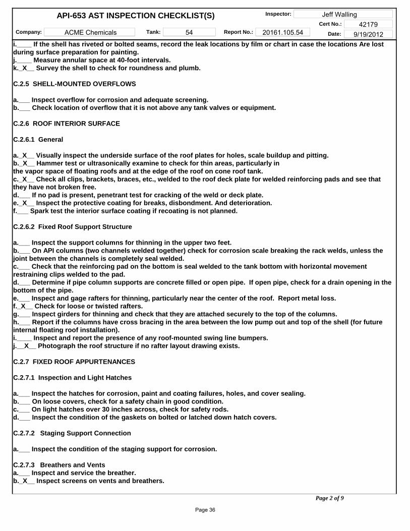
C.2.6 ROOF INTERIOR SURFACE
C.2.6.1 General
a._X__ Visually inspect the underside surface of the roof plates for holes, scale buildup and pitting.b._X__ Hammer test or ultrasonically examine to check for thin areas, particularly in the vapor space of floating roofs and at the edge of the roof on cone roof tank.c._X__ Check all clips, brackets, braces, etc., welded to the roof deck plate for welded reinforcing pads and see that they have not broken free.d.___ If no pad is present, penetrant test for cracking of the weld or deck plate.e._X__ Inspect the protective coating for breaks, disbondment. And deterioration.f.___ Spark test the interior surface coating if recoating is not planned.
C.2.6.2 Fixed Roof Support Structure
a.___ Inspect the support columns for thinning in the upper two feet.b.___ On API columns (two channels welded together) check for corrosion scale breaking the rack welds, unless the joint between the channels is completely seal welded.c.___ Check that the reinforcing pad on the bottom is seal welded to the tank bottom with horizontal movement restraining clips welded to the pad.d.___ Determine if pipe column supports are concrete filled or open pipe. If open pipe, check for a drain opening in the bottom of the pipe.e.___ Inspect and gage rafters for thinning, particularly near the center of the roof. Report metal loss.f._X__ Check for loose or twisted rafters.g.___ Inspect girders for thinning and check that they are attached securely to the top of the columns.h.___ Report if the columns have cross bracing in the area between the low pump out and top of the shell (for future internal floating roof installation).i.____ Inspect and report the presence of any roof-mounted swing line bumpers.j.__X__ Photograph the roof structure if no rafter layout drawing exists.
C.2.7 FIXED ROOF APPURTENANCES
C.2.7.1 Inspection and Light Hatches
a.___ Inspect the hatches for corrosion, paint and coating failures, holes, and cover sealing.b.___ On loose covers, check for a safety chain in good condition.c.___ On light hatches over 30 inches across, check for safety rods.d.___ Inspect the condition of the gaskets on bolted or latched down hatch covers.
C.2.7.2 Staging Support Connection
a.___ Inspect the condition of the staging support for corrosion.
C.2.7.3 Breathers and Ventsa.___ Inspect and service the breather.b._X__ Inspect screens on vents and breathers.
Page 2 of 9
Page 36

Company: ACME Chemicals Tank: 54 Report No.: 20161.105.54 Date: 9/19/2012
Inspector: Jeff WallingCert No.: 42179
API-653 AST INSPECTION CHECKLIST(S)
C.2.7.4 Emergency P/V Hatches
a.___ Inspect and service pressure/vacuum hatches. (Setting should be high enough to prevent chattering of breather during normal operation. See breather manufacturer's guide.)b.___ Inspect liquid seal hatches for corrosion and proper liquid level in the seal.
C.2.7.5 Sample Hatch
a.___ Inspect sample hatch for corrosion.b.___ Check that the cover operates properly.c.___ If the tank has no gagewell, check for a hold off distance marker and check measurement.
C.2.8 FLOATING ROOF
C.2.8.1 Roof Deck
a.___ Hammer test the area between roof rim and shell. (If access for hammer testing is inadequate, measure the distance from the bottom edge of the roof to the corroded area and then hammer test from inside the pontoon.)b.___ In sour water service, clean and test all deck plate weld seams for cracking unless the lower laps have been seal welded.c.___ Check that either the roof drain is open or the drain plug in the roof is open in case of unexpected rain.d.___ On flat bottomed and cone down bottom roof decks, check for a vapor dam around the periphery of the roof. The dam should be continuous without break to prevent escape of vapors to the seal area from under the center of the roof.
C.2.8.2 Floating Roof Pontoons
a.___ Visually inspect each pontoon for liquid leakage.b.___ Run a light wire through the gooseneck vents on locked down inspection hatch covers to make sure they are open.c.___ Inspect lockdown latches on each cover.d.___ Check and report if each pontoon is:(1)___ Vapor tight (bulkhead seal welded on one side on bottom, sides, and (top).(2)___ Liquid tight (seal welded on bottom and sides only) or(3)___ Unacceptable (minimum acceptable condition is liquid tight).
C.2.8.3 Floating Roof Cutouts
a.___ Inspect underside of cutouts for mechanical damage.b.___ Inspect welds for cracks.c.___ Inspect plate for thinning, pitting and erosion.d.___ Measure mixer cutouts and record plate thickness for future mixer installation or replacement. Plate thickness:_____
C.2.8.4 Floating Roof Supports
a.___ Inspect fixed low and removable high floating roof legs for thinning.b.___ Inspect for notching at bottom of legs for drainage.c.___ Inspect for leg buckling or belling at bottom.d.___ Inspect pin hole in roof guide for tears.e.___ Check plumb of all legs.f.___ inspect for adequate reinforcing gussets on all legs through a single portion of the roof.g.___ Inspect the area around the roof legs for cracking if there is no internal reinforcing pad or if the topside pad is not welded to the deck plate on the underside.h.___ Inspect the sealing system on the two-position legs and the vapor plugs in the fixed low leg for deterioration of the gaskets.i.____ On all mounted roof supports, check for adequate clearance based on the maximum floating roof movement as determined by the position of the roof relative to the gagewell and/or counter rotational device.
Page 3 of 9
Page 37
Company: ACME Chemicals Tank: 54 Report No.: 20161.105.54 Date: 9/19/2012
Inspector: Jeff WallingCert No.: 42179
API-653 AST INSPECTION CHECKLIST(S)
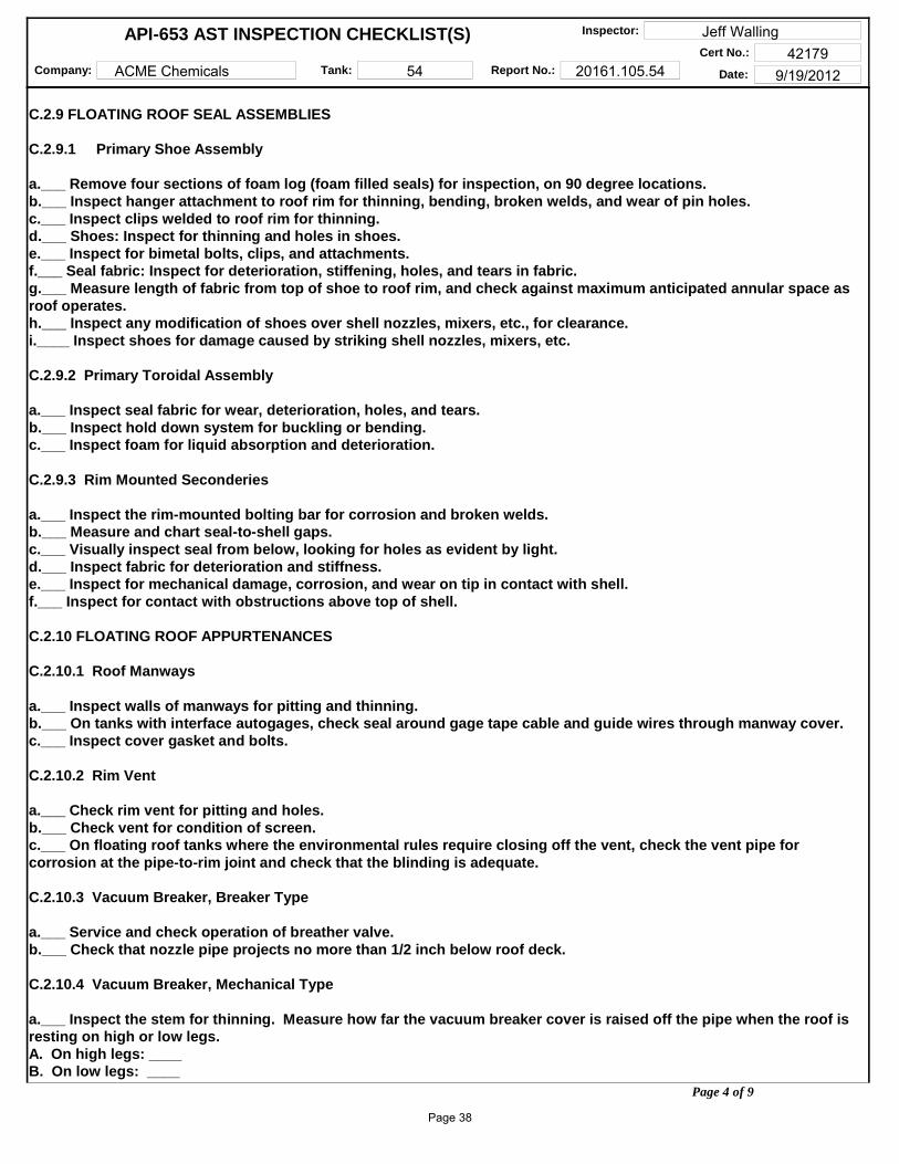
C.2.9 FLOATING ROOF SEAL ASSEMBLIES
C.2.9.1 Primary Shoe Assembly
a.___ Remove four sections of foam log (foam filled seals) for inspection, on 90 degree locations.b.___ Inspect hanger attachment to roof rim for thinning, bending, broken welds, and wear of pin holes.c.___ Inspect clips welded to roof rim for thinning.d.___ Shoes: Inspect for thinning and holes in shoes.e.___ Inspect for bimetal bolts, clips, and attachments.f.___ Seal fabric: Inspect for deterioration, stiffening, holes, and tears in fabric.g.___ Measure length of fabric from top of shoe to roof rim, and check against maximum anticipated annular space as roof operates.h.___ Inspect any modification of shoes over shell nozzles, mixers, etc., for clearance.i.____ Inspect shoes for damage caused by striking shell nozzles, mixers, etc.
C.2.9.2 Primary Toroidal Assembly
a.___ Inspect seal fabric for wear, deterioration, holes, and tears.b.___ Inspect hold down system for buckling or bending.c.___ Inspect foam for liquid absorption and deterioration.
C.2.9.3 Rim Mounted Seconderies
a.___ Inspect the rim-mounted bolting bar for corrosion and broken welds.b.___ Measure and chart seal-to-shell gaps.c.___ Visually inspect seal from below, looking for holes as evident by light.d.___ Inspect fabric for deterioration and stiffness.e.___ Inspect for mechanical damage, corrosion, and wear on tip in contact with shell.f.___ Inspect for contact with obstructions above top of shell.
C.2.10 FLOATING ROOF APPURTENANCES
C.2.10.1 Roof Manways
a.___ Inspect walls of manways for pitting and thinning.b.___ On tanks with interface autogages, check seal around gage tape cable and guide wires through manway cover.c.___ Inspect cover gasket and bolts.
C.2.10.2 Rim Vent
a.___ Check rim vent for pitting and holes.b.___ Check vent for condition of screen.c.___ On floating roof tanks where the environmental rules require closing off the vent, check the vent pipe for corrosion at the pipe-to-rim joint and check that the blinding is adequate.
C.2.10.3 Vacuum Breaker, Breaker Type
a.___ Service and check operation of breather valve.b.___ Check that nozzle pipe projects no more than 1/2 inch below roof deck.
C.2.10.4 Vacuum Breaker, Mechanical Type
a.___ Inspect the stem for thinning. Measure how far the vacuum breaker cover is raised off the pipe when the roof is resting on high or low legs.A. On high legs: ____B. On low legs: ____
Page 4 of 9
Page 38

Company: ACME Chemicals Tank: 54 Report No.: 20161.105.54 Date: 9/19/2012
Inspector: Jeff WallingCert No.: 42179
API-653 AST INSPECTION CHECKLIST(S)
C.2.10.5 Roof Drains: Open Systems, Including Emergency Drains
a.___ Check liquid level inside open roof drains for adequate freeboard. Report if there is insufficient distance between liquid level and top of drain.b.___ If tank comes under Air Quality Monitoring District rules, inspect the roof drain vapor plug.c.___ If emergency drain is not at the center of the roof, check that there are at least three emergency drains.
C.2.10.6 Closed Drain Systems: Drain Basins
a.___ Inspect for thinning and pitting.b.___ Inspect protective coating (topside).c.___ Inspect basin cover or screen for corrosion.d.___ Test operation of check valve.e.___ Check for presence of check valve where bottom of basin is below product level.f.___ Inspect drain basin(s) to roof deck welds for cracking.g.___ Check drain basin(s) outlet pipe for adequate reinforcement to roof deck (including reinforcing pad).
C.2.10.7 Closed Drain Systems: Fixed Drain Line on Tank Bottom
a.___ Hammer test fixed drain line on tank bottom for thinning and scale/debris plugging.b.___ Inspect supports and reinforcing pads for weld failures and corrosion.c.___ Check that pipe is guided, not rigidly locked to supports, to avoid tearing of tank bottom plate.
C.2.10.8 Closed Drain Systems: Flexible Pipe Drain
a.___ Inspect for damage to exterior of pipe.b.___ Check for obstructions that pipe could catch on.c.___ Inspect shields to protect pipe from snagging.d.___ Inspect results of hydrotest on flexible roof drain system.
C.2.10.9 Closed Drain Systems: Articulated Joint Drain
a.___ Hammer test rigid pipe in flexible joint system for thinning and scale/debris plugging.b.___ Inspect system for signs of bending or strain.c.___ Inspect results of system hydrotest.d.___ Inspect landing leg and pad.
C.2.10.10 Autogage System and Alarms
a.___ Check freedom of movement of tape through autogage tape guide.b.___ Inspect sheaves for freedom of movement.c.___ Test operation checker.d.___ Inspect tape and tape cable for twisting and fraying.e.___ Test the tape's freedom of movement through guide sheaves and tape guide pipe.f.___ On open-top tanks, check that gate tapes with cables have no more than one foot of tape exposed with float at lowest point.g.___ Check float for leakage.h.___ Test float guide wire anchors for spring action by pulling on wire and releasing.i.____ Inspect floatwells in floating roofs for thinning and pitting of walls just above the liquid level.j.____ Check that the autogage tape is firmly attached to the float.k.___ Inspect the tape cable and float guide wire fabric seals through the float well cover.l.___ Inspect the bottom guide wire attachment clip. Inspect for a temporary weighted bar instead of a permanent welded down clip.m.___ Inspect board-type autogage indicators for legibility and freedom of movement of indicator.n.___ Measure and record these distances to determine if seal damage will occur if tank is run over:(1)____ From shell top angle to underside of tape guide system,
Page 5 of 9
Page 39
Company: ACME Chemicals Tank: 54 Report No.: 20161.105.54 Date: 9/19/2012
Inspector: Jeff WallingCert No.: 42179
API-653 AST INSPECTION CHECKLIST(S)
(2)____ From liquid level on floating top to top of secondary seal.o.___ Identify floating roofs where the tape is connected directly to the roof.p.___ Overfill alarm: Inspect tank overfill prevention alarm switches for proper operation.
C.2.11 COMMON TANK APPURTENANCES
C.2.11.1 Gage well
a.___ Inspect gage well pipe for thinning at about two-thirds distance above the bottom: look for thinning at the edge of the slots.b.___ Check for corrosion on the pipe joint. Check that sample cords, weights, thermometers, etc., have been removed from the pipe.c.___ Check for cone at bottom end of pipe about one foot above the bottom.d.___ Check condition of well washer pipe and that its flared end is directed at the near side of the hold off pad.e.___ Check that supports for gage well are welded to pad or to shell and not directly to bottom plate.f.___ Check operation of gage well cover.g.___ Check presence of a hold-off distance marker in well pipe and record hold-off distance. ____ Hold-off Distance.h.___ Identify and report size and pipe schedule, and whether pipe is solid or slotted. Report slot size.i.____ Check that the hold-off distance plate is seal welded to the bottom and that any gagewell supports are welded to the plate and not directly to the bottom.j.____ Inspect vapor control float and cable.k.___ Check for presence and condition of gagewell washer.l.____ Check for bull plug or plate blind on gagewell washer valve.m.___ Inspect gage well guide in floating roof for pitting and thinning.n.___ Inspect the guide rollers and sliding plates for freedom of movement.o.___ Inspect condition of gagewell pipe seal system.p.___ On black oil and diesel services: if gagewell is also used for sampling, check for presence of a thief- and gage-type hatch to avoid spillage.q.___ Visually inspect inside of pipe for pipe weld protrusions which could catch or damage vapor control float.
C.2.11.2 Sampling Systems: Roof Sample Hatches
a.___ Inspect roof mounted sample hatches for reinforcing pads and cracking.b.___ Inspect cover for operation.c.___ For tanks complying with Air Quality Monitoring District rules, inspect sample hatch covers for adequate sealing.d.___ Check horizontal alignment of internal floating roof sample hatches under fixed roof hatches.e.___ Inspect the sealing system on the internal floating roof sample hatch cover.f.___ Inspect floating roof sample hatch cover recoil reel and rope.
C.2.11.3 Shell Nozzles
a._X__ Inspect shell nozzles for thinning and pitting.b.___ Inspect hot tap nozzles for trimming of holes.c._X__ Identify type of shell nozzles.d._X__ Identify and describe internal piping, including elbow up and elbow down types.
C.2.11.4 For Nozzles Extended Into the Tank
a.___ Inspect pipe support pads welded to tank bottom.b.___ Inspect to see that pipe is free to move along support without strain or tearing action on bottom plate.c.___ Inspect nozzle valves for packing leaks and damaged flange faces.d.___ Inspect heater steam nozzle flanges and valves for wire cutting.e.___ Report which nozzles have thermal pressure relief bosses and valves.f.___ In internal elbow-down fill line nozzles, inspect the wear plate on the tank bottom.g.___ On elbow-up fill lines in floating roof tanks, check that opening is directed against underside of roof, not against vapor space. Inspect impact area for erosion.
Page 6 of 9
Page 40

Company: ACME Chemicals Tank: 54 Report No.: 20161.105.54 Date: 9/19/2012
Inspector: Jeff WallingCert No.: 42179
API-653 AST INSPECTION CHECKLIST(S)
C.2.11.5 Diffusers and Air Rolling Systems
a.___ Inspect diffuser pipe for erosion and thinning.b.___ Check holes in diffuser for excessive wear and enlargement.c.___ Inspect diffuser supports for damage and corrosion.d.___ Check that diffuser supports restrain, not anchor, longitudinal line movement.e.___ Inspect air spiders on bottom of lube oil tanks for plugging and damaged or broken threaded joints.
C.2.11.6 Swing Lines
a.___ Inspect flexible joint for cracks and leaks.b.___ Scribe the flexible joint across the two moving faces and raise end of swingline to check the joint's freedom of movement, indicated by separation of scribe marks.c.___ Check that flexible joints over six inches are supported.d.___ Inspect the swing pipe for deep pitting and weld corrosion.
e.___ Loosen the vent plugs in the pontoons and listen for a vacuum. Lack of a vacuum indicates a leaking pontoon.f.___ Check the results of air tests on pontoons during repairs.g.___ Inspect the pontoons for pitting.h.___ Inspect the pull-down cable connections to the swing.i.____ Inspect the condition of the bottom-mounted support, fixed roof limiting bumper or shell mounted limiting bumper for wood condition, weld and bolt corrosion and seal welding to bottom or shell.j.____ Inspect safety hold-down chain for corrosion and weak links.k.___ Check that there is a welded reinforcing pad where the chain connects to the bottom.l.___ If the floating swing in a floating or internal floating roof tank does not have a limiting device preventing the swing from exceeding 60 degrees, measure and calculate the maximum angle possible with the roof on overflow.____ Max. angle on overflow (If the calculated angle exceeds 65 degrees, recommend installation of a limiting bracket.)m.___ Inspect pull down cable for fraying.n.___ Inspect for three cable clamps where cable attaches to end of swingline (single-reeved) or to roof assembly (double-reeved). Inspect sheaves for freedom of movement.o.___ Inspect winch operation and check the height indicator for legibility and accuracy.p.___ Inspect bottom-mounted sheave assembly at end of pontoon for freedom of rotation of sheave.q.___ Inspect shell-mounted lower sheave assembly for freedom of rotation of sheave, corrosion thinning and pitting of sheave housing.r.___ Inspect upper sheave assembly for freedom of movement of sheave.s.___Inspect the cable counterbalance assembly for corrosion and freedom of operation.
C.2.11.7 Manway Heater Racks
a.___ Inspect the manway heater racks for heater welds and bending of the sliding rails.b.___ Measure and record the length of the heater and length of the track.
C.2.11.8 Mixer Wear Plates and Deflector Stands
a.___ Inspect bottom and shell plates and deflector stands.b.___ Inspect for erosion and corrosion on the wear plates. Inspect for rigidity, structural soundness, corrosion and erosion of deck plates and reinforcing pads that are seal welded to the bottom under the deflector stand legs.c.___ Measure for propeller clearance between the bottom of deflector stand and roof when the roof is on low legs.
C.2.12 ACCESS STRUCTURES
C.2.12.1 Handrails
a._X__ Identify and report type (steel pipe, galvanized pipe, square tube, angle) and size of handrails.b._X__ Inspect for pitting and holes, paint failure.c._X__ Inspect attachment welds.d._X__ Identify cold joints and sharp edges. Inspect the handrails and midrails.
Page 7 of 9
Page 41

Company: ACME Chemicals Tank: 54 Report No.: 20161.105.54 Date: 9/19/2012
Inspector: Jeff WallingCert No.: 42179
API-653 AST INSPECTION CHECKLIST(S)
e._X__ Inspect safety drop bar (or safety chain) for corrosion, functioning, and length.f.___ Inspect the handrail between the rolling ladder and the gaging platform for a hazardous opening when the floating roof is at its lowest level.
C.2.12.2 Platform Frame
a._X__ Inspect frame for corrosion and paint failure.b._X__ Inspect the attachment of frame to supports and supports to tank for corrosion and weld failure.c.___ Check reinforcing pads where supports are attached to shell or roof.d._X__ Inspect the surface that deck plate or grating rests on, for thinning and holes.e._X__ Check that flat-surface to flat-surface junctures are seal welded.
C.2.12.3 Deck Plate and Grating
a._X__ Inspect deck plate for corrosion-caused thinning or holes (not drain holes) and paint failure.b._X__ Inspect plate-to-frame weld for rust scale buildup.c._X__ Inspect grating for corrosion-caused thinning of bars and failure of welds.d._X__ Check grating tie down clips. Where grating has been retrofitted to replace plate, measure the rise of the step below and above the grating surface and compare with other risers on the stairway.
C.2.12.4 Stairway Stringers
a.___ Inspect spiral stairway stringers for corrosion, paint failure and weld failure. Inspect attachment of stairway treads to stringer.b.___ Inspect stairway supports to shell welds and reinforcing pads.c.___ Inspect steel support attachment to concrete base for corrosion.
C.2.12.5 Rolling Ladder
a.___ Inspect rolling ladder stringers for corrosion.b.___ Identify and inspect ladder fixed rungs (square bar, round bar. angles) for weld attachment to stringers and corrosion, particularly where angle rungs are welded to stringers.c.___ Check for wear and corrosion where rolling ladder attaches to gaging platform.d.___ Inspect pivot bar for wear and secureness.e.___ Inspect operation of self-leveling stairway treads.f.___ Inspect for corrosion and wear on moving parts.g.___ Inspect rolling ladder wheels for freedom of movement, flat spots, and wear on axle.h.___ Inspect alignment of rolling ladder with roof rack.i.____Inspect top surface of rolling ladder track for wear by wheels to assure at least 18 inches of unworn track (track long enough).j.____ Inspect rolling ladder track welds for corrosion.k.___ Inspect track supports on roof for reinforcing pads seal welded to deck plate.l.___ Check by dimensioning, the maximum angle of the rolling ladder when the roof is on low legs. Max. angle: _____m.___If rolling ladder track extends to within five feet of the edge of the roof on the far side, check for a handrail on the top of the shell on that side.
Page 8 of 9
Page 42

APPENDIX E
Inspection Photographs
Page 43
ACME CHEMICALS - TK-54 REPORT –20161.105.54 INSPECTION PHOTOGRAPHS
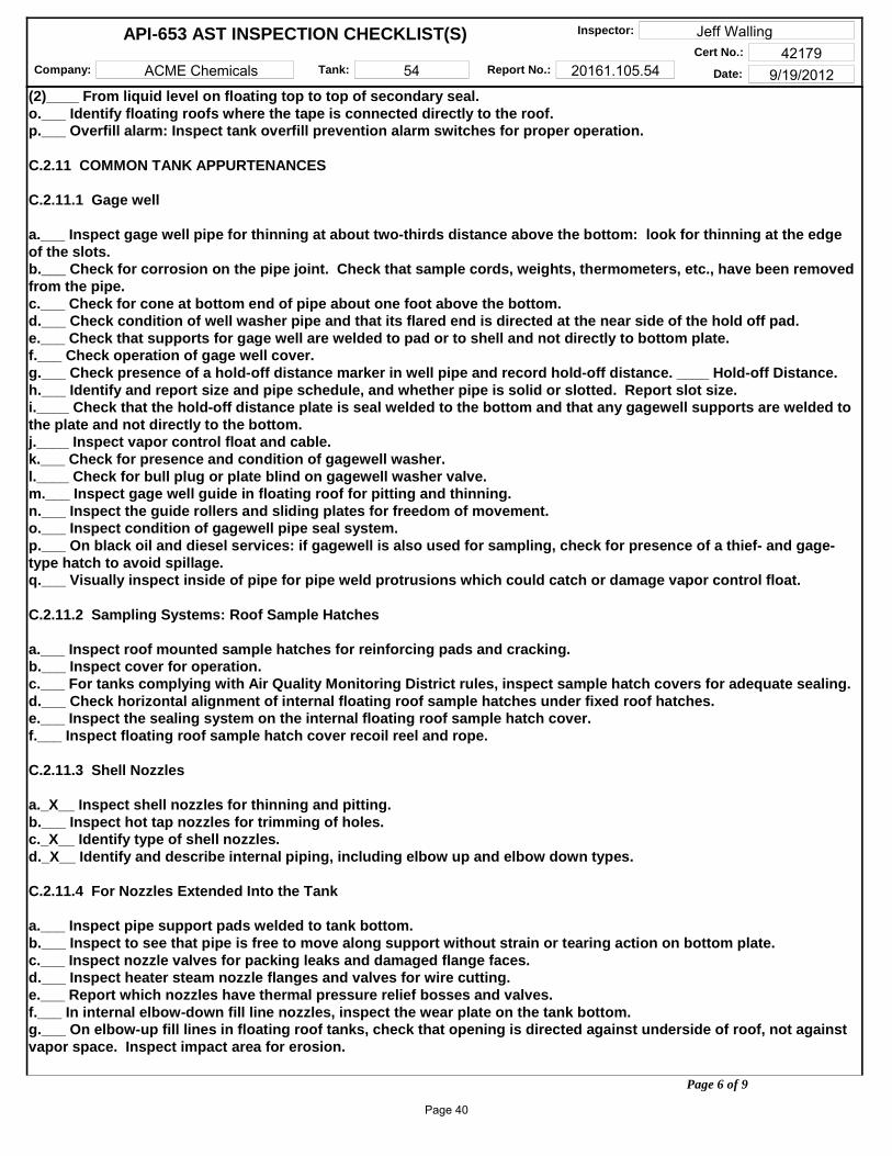
Tank 54
Mechanical induced shell bulge/crack.
Page 44

ACME CHEMICALS - TK-54 REPORT –20161.105.54 INSPECTION PHOTOGRAPHS
Shell cracked at toe of chime weld
Area of shell deformation and coating failure.
Page 45

ACME CHEMICALS - TK-54 REPORT –20161.105.54 INSPECTION PHOTOGRAPHS
Shell deformation at the building interface
Shell deformation on the East side on every shell course.
Page 46
ACME CHEMICALS - TK-54 REPORT –20161.105.54 INSPECTION PHOTOGRAPHS
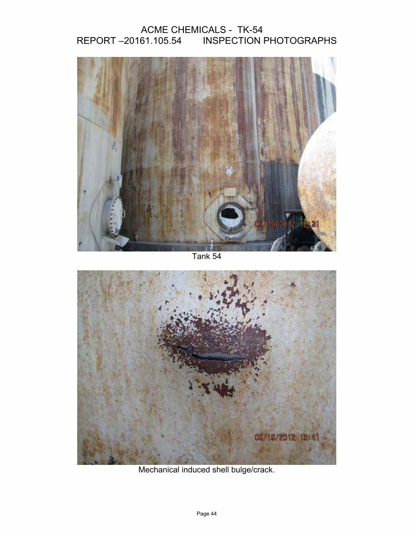
Shell deformation on East side course 2
Square shell reinforcement plates welded to the shell.
Page 47

ACME CHEMICALS - TK-54 REPORT –20161.105.54 INSPECTION PHOTOGRAPHS
Old platform support brace cut and left attached to shell.
Area of severe corrosion on the tank bottom lip extension (chime) on the E. side.
Page 48
ACME CHEMICALS - TK-54 REPORT –20161.105.54 INSPECTION PHOTOGRAPHS
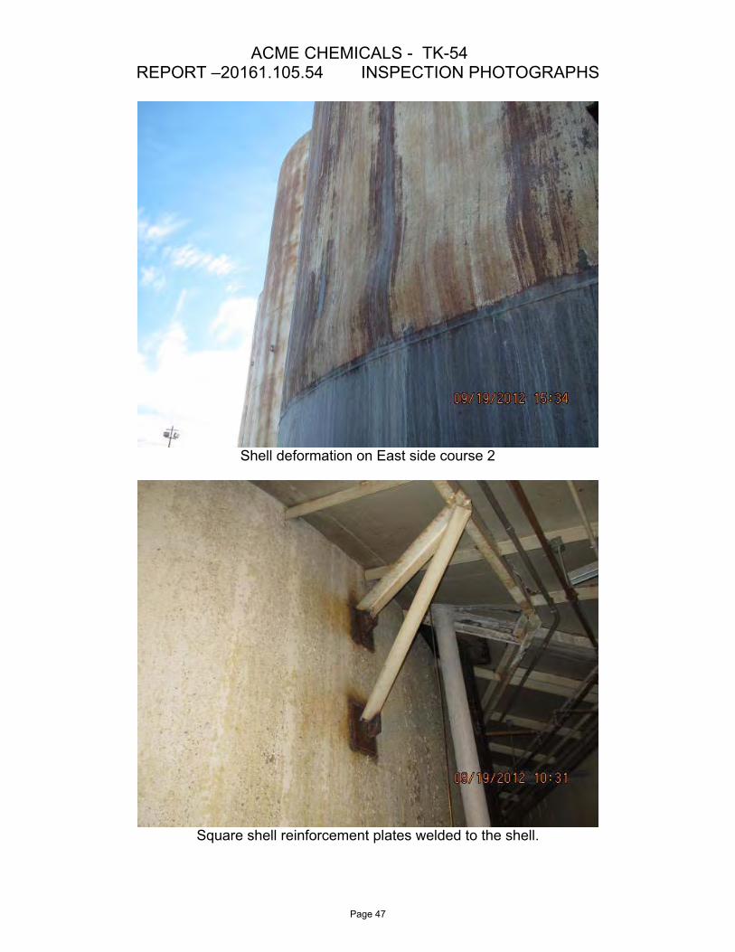
Residual product in the 24-inch shell manway.
The 6-inch product (shell nozzle E) coated with product.
Page 49

ACME CHEMICALS - TK-54 REPORT –20161.105.54 INSPECTION PHOTOGRAPHS
Grout foundation cap (shell bearing surface) deteriorated.
Cracking in the concrete ringwall.
Page 50
ACME CHEMICALS - TK-54 REPORT –20161.105.54 INSPECTION PHOTOGRAPHS
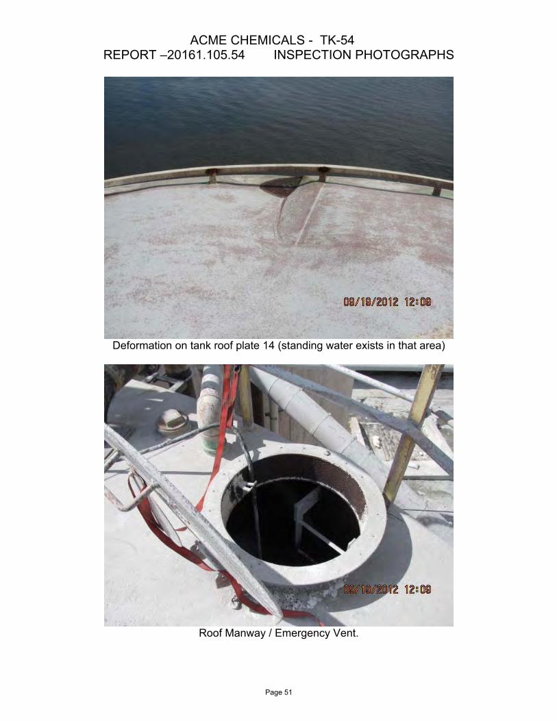
Deformation on tank roof plate 14 (standing water exists in that area)
Roof Manway / Emergency Vent.
Page 51

ACME CHEMICALS - TK-54 REPORT –20161.105.54 INSPECTION PHOTOGRAPHS
Improper roof vent configuration & coating failure on vent hood.
Coating failure on the fixed tank roof.
Page 52

ACME CHEMICALS - TK-54 REPORT –20161.105.54 INSPECTION PHOTOGRAPHS
Severe mechanical damage on the tank bottom plates at the door sheet cutout.
Residual product throughout the tank interior.
Page 53
ACME CHEMICALS - TK-54 REPORT –20161.105.54 INSPECTION PHOTOGRAPHS
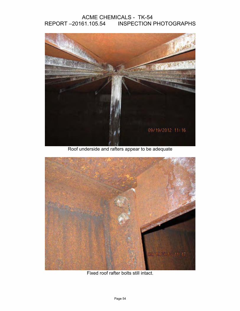
Roof underside and rafters appear to be adequate
Fixed roof rafter bolts still intact.
Page 54
APPENDIX F
1) Venting Requirements per API-650
2) API 2000 Vent Evaluation for 8" Normal Vent
3) API-650 App. F Calculations
4) API 2000 Vent Evaluation for Restricted Normal Vent
5) API-650 Appendix V Evaluation
Venting Calculations
Page 55

VENTING EVALAUTION FOR TANK 54 IN THE ACME CHEMICALS CHESTER, PA FACILITY.
Venting Requirements per API-650:
5.8.5 Roof Venting 5.8.5.1 Tanks designed in accordance with this Standard and having a fixed roof shall be vented for both normal conditions. (resulting from operational requirements, including maximum filling and emptying rates, and atmospheric temperature changes) and emergency conditions (resulting from exposure to an external fire). Tanks with both a fixed roof and a floating roof satisfy these requirements when they comply with the circulation venting requirements of Appendix H. All other tanks designed in accordance with this Standard and having a fixed roof shall meet the venting requirements of 5.8.5.2 and 5.8.5.3. 5.8.5.2 Normal venting shall be adequate to prevent internal or external pressure from exceeding the corresponding tank design pressures and shall meet the requirements specified in API Std 2000 for normal venting. 5.8.5.3 Emergency venting requirements are satisfied if the tank is equipped with a weak roof-to-shell attachment (frangible joint) in accordance with 5.10.2.6, or if the tank is equipped with pressure relief devices meeting the requirements specified in API Std 2000 for emergency venting. When pressure relief devices are used to satisfy the emergency venting requirements, they shall achieve the flow rates specified in API Std 2000 without exceeding the following limits on internal pressure: a. For unanchored tanks, the pressure relief devices shall be adequate to prevent internal pressure fromexceeding the tank design pressure as determined in F.4.1 (subject to the limitations in F.4.2 and F.4.3, as applicable). In calculating limitations per F.4.2, use M = 0. b. For anchored tanks, except those designed to F.1.3, the pressure relief devices shall be adequate toprevent internal pressure from exceeding the tank design pressure as determined in F.4.1 (subject to the limitations in F.4.3, as applicable). c. For tanks designed to F.1.3 (anchored tanks), the pressure relief devices shall be adequate to preventinternal pressure from exceeding the design pressure specified by the Purchaser. 5.8.5.5 Corrosion-resistant coarse-mesh bird screens (13 mm [1/2 in.] nominal openings) shall protect all free vents.
Existing Normal Vent:
NFPA and UL-142 recommend a vent that is equal to the larger of the inlet or outlet product sizes, which in this case would be a 10” vent. The tank original design code, API-12C, (which preceded the API-650 Standard (the latest AST design code)) is an out of date code; therefore, the latest API-650 & API 2000 Standards were referenced based on the API-653 Standard recommendations (API-653 1.1, 4.2.4.5, & C.2.7.4 (cklst)) and API-575 5.5.
Vent area for existing 8” Sch 80 Pipe (where D = 8.635”(OD) – (2*0.50”)(thickness) = 7.625” (ID)). (Av) = (7.625/2)^2*PI() = 46.7in^2.
Vent area in the existing vent hat gap over vent (Ag) = 7.625*PI() *.125 = 3in^2 (equating to a 2” vent area (approximately)).
The gap is restricting the area to only 6.4% of the full area that would be provided by the 8” nozzle and is therefore not satisfactory for use as a normal vent.
Venting capacities based on formula found throughout API Publications for Venting (i.e., API 12F Table C2, API 12B Table C2, et)
Pump-in/Pump-out flow rates were based on pump rates provided by PQ Corp.
Page 56

VENTING EVALAUTION FOR TANK 54 IN THE ACME CHEMICALS CHESTER, PA FACILITY.
Existing Emergency Vent:
Emergency Vent – Area (Ac) of 24” MW Cover = (32.75/2)^2 * 3.1416 = 842.4 in^2, MW Cover Thickness (t) = 0.375”, Weight of Steel (Ws)/in^3 = 0.2833psig, MW Cover Weight (Wt) =Ac * t * Ws = 89lbs. The MW Cover acting as an emergency vent is providing a resistance pressure of Ws * t = 0.106 psi (2.94 wc) resistance.
Emergency Venting i.a.w App F = 4.526wc (0.163psi) which is greater than the resistance pressure of the WM Cover (2.94wc) and is therefore satisfactory as use as an emergency vent. (API-2000 4.4.2)
Venting capacities based on formula found throughout API Publications for Venting (i.e., API 12F Table C2, API 12B Table C2, et)
Tank Design Maximum Allowable Working Pressure (MAWP) in accordance with the API-650 and API-653 Standards:
Per API-650/653 Design Internal Pressure = weight of roof in corroded condition for open vent tank (0.09” thick) = 0.09*0.2833 = 0.71wc (0.026psi) (API-650 5.10.2 & API-653 4.2.1.2 )
Per API-650 Design External Pressure = 1wc (0.036 psi) (API-650 5.2.1)
Other Considerations:
Due to product being a water base substance, it is possible that the quenching effect on the tank during hot day rain storms may have a greater vacuum effect than estimated by the formula above (which is based on petroleum product considering only the moisture in the air from humid days. Drawing a vacuum on a heated water based product may cause an increase in the off rate of the vapors that would feed into the condensing process causing any vacuum to be sustained or increased beyond the normal expectation of the API-2000 formula.
Page 57
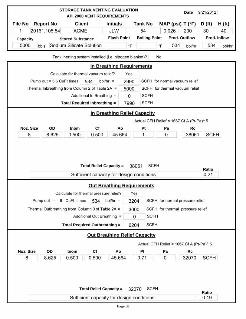
API 2000 VENT REQUIREMENTS
STORAGE TANK VENTING EVALUATION
File No
1Report No
20161.105.54Initials
JLWClient
ACMETank No
54
Date 9/21/2012
MAP (psi)
0.026 30D (ft)
40H (ft)
Flash Point Boiling Point
°F
Prod. Outflow
534 bbl/hr
Prod. Inflow
534 bbl/hr
Capacity
5000Stored Substance
Sodium Silicate Solution °Fbbls
T (°F)
200
bbl/hr = 534
Total Required Inbreathing = 7990
In Breathing Requirements
SCFH
Thermal Inbreathing from Column 2 of Table 2A = 5000 SCFH for thermal vacuum relief2990 SCFH for normal vacuum reliefPump out = 5.6 CuFt times
Calculate for thermal vacuum relief?
of Table 2A = Column 3
Actual CFH Relief = 1667 Cf A (Pt-Pa)^.5
In Breathing Relief Capacity
tnom
0.500OD
8.625Ao
45.664Pt
1Pa
0Rc
38061
Total Relief Capacity = 38061
Sufficient capacity for design conditions
SCFHRatio0.21
bbl/hr = 534
Total Required Outbreathing = 6204
Out Breathing Requirements
SCFH
Thermal Outbreathing from 3000 SCFH for thermal pressure relief
3204 SCFH for normal pressure relief
Actual CFH Relief = 1667 Cf A (Pt-Pa)^.5
Out Breathing Relief Capacity
tnom
0.500OD
8.625Ao
45.664Pt
0.71Pa
0Rc
32070
Total Relief Capacity = 32070
Sufficient capacity for design conditions
SCFHRatio0.19
Calculate for thermal pressure relief?
CuFt times6Pump out =
Yes
Noz. Size
8
Yes
Noz. Size
8
SCFH
SCFH
Tank inerting system installed (i.e. nitrogen blanket)? No
Additional In Breathing = 0 SCFH
Additional Out Breathing = 0 SCFH
Cf
0.500
Cf
0.500
Page 58
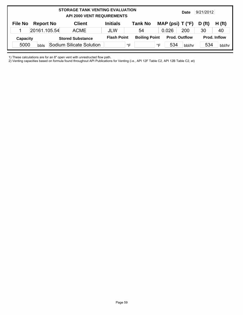
API 2000 VENT REQUIREMENTS
STORAGE TANK VENTING EVALUATION
File No
1Report No
20161.105.54Initials
JLWClient
ACMETank No
54
Date 9/21/2012
MAP (psi)
0.026 30D (ft)
40H (ft)
Flash Point Boiling Point
°F
Prod. Outflow
534 bbl/hr
Prod. Inflow
534 bbl/hr
Capacity
5000Stored Substance
Sodium Silicate Solution °Fbbls
T (°F)
200
1) These calculations are for an 8" open vent with unrestructed flow path.2) Venting capacities based on formula found throughout API Publications for Venting (i.e., API 12F Table C2, API 12B Table C2, et)
Page 59

API 2000 VENT REQUIREMENTS
STORAGE TANK VENTING EVALUATION
File No
1Report No
20161.105.54Initials
JLWClient
ACMETank No
54
Date 9/21/2012
MAP (psi)
0.026 30D (ft)
40H (ft)
Flash Point Boiling Point
°F
Prod. Outflow
534 bbl/hr
Prod. Inflow
534 bbl/hr
Capacity
5000Stored Substance
Sodium Silicate Solution °Fbbls
T (°F)
200
Tank roof attached with frangible joint? Emergency venting requiredTank subject to fire exposure?
Tank bottom subject to fire exposure? (i.e., elevated tank on legs)
Q
14090000A
2827.4F
1L T M
SCFH
H limit (ft)
Venting Requirements calculated SCFH Relief = 3.091*(QF/L)*(T/M)^.5
30 2827Wetted Area
Ft^2 SCFH
Venting requirements may be determined by either of the following methods. Evaluation 1 is a general estimate where Evaluation 2 is a more accurate evaluation
Evaluation 1
Evaluation 2
Venting Requirements SCFH Relief = 1107*F*A^.82
742000 SCFH
Venting Requirements from Table 3A
2827Wetted Area
Ft^2
Venting Requirements
Venting Requirements
Actual CFH Relief = 1667 Cf A (Pt-Pa)^.5
Emergency Relief Capacity
tnom
0.250OD
24Ao
433.737Pt
4.526Pa
0RC
769112
Total Relief Capacity = 850084
Sufficient capacity for design conditions
SCFHRatio0.87
SCFHVenting Required = 742000
(Emerg. + Normal)
0 % Bttm exp
409000
(Table 3A)
(Equation 2A)
Emergency Venting Requirements for Vertical Tanks
F Factor
1
Yes
No
No
Venting Requirements
Calc Eq. 2A
Noz. Size
24 SCFH
1) All conditions are satisfactory with the 24" Emergency Vent & 8" Open Vent providing sufficient capacity for emergency and normal operating conditions with unrestructed flow path.2) Emergency Vent cover area of 24in MW Cover at 0.375 inch thick = 842.4in^2 at a weight Wt of 89lbs = 0.106 psi (2.94 wc) resistance under emergency relief conditions (App. F results in 4.526wc allowed in emergency conditions) which is satisfactory for the emergency venting means per API-2000 4.4.2.
4.526 0Cf
0.500
PaPt
Page 60

API 2000 VENT REQUIREMENTS
STORAGE TANK VENTING EVALUATION
File No
1Report No
20161.105.54Initials
JLWClient
ACMETank No
54
Date 9/21/2012
MAP (psi)
0.026 30D (ft)
40H (ft)
Flash Point Boiling Point
°F
Prod. Outflow
534 bbl/hr
Prod. Inflow
534 bbl/hr
Capacity
5000Stored Substance
Sodium Silicate Solution °Fbbls
T (°F)
200
Where;Rc = Relief Capacity, CFHCF = Flow CoEff. of circular orifice. use (0.5) if unknown for conservative estimate or if device is based on the calculated method (in lue of testing) as stamped on the nameplate. (use 0.710 to closely match NFPA 30 and Morrison Vent Guide venting capacities for open pipe at 12" max length)Ao = Area of orifice, in^2Pt = Pressure on + side of orifice (in. of water). Pa = Pressure on - side of orifice (in. of water)CFH = venting requirement, in cubic feet per hour of air,Q = heat input from fire exposure, in BTU per hour. Heat input is provided in Figure B-1 of Appendix B or the following summary:
Wetted Surface Area / Design Pressure / Heat Input (square feet) / (psig) / (Btu/hr)<200 / <=15 / Q = 20,000A200 and <1000 / <=15 / Q = 199,300A^0.5661000 and <2800 / <=15 / Q = 963,400A^0.3382800 / 1 psig and 15 / Q = 21,000A^0.822800 / <=1 / Q = 14,090,000
A = wetted surface area of the tank, in square feet (see Table 3A, Footnotes a and b), The wetted area is equal to the total surface area of the vertical shell to a height of 30 feet (9.14 meters) above grade.F = environmental factor from Table 4A. Credit may be taken for only one environmental factor,L = latent heat of vaporization of the stored liquid at the relieving press. and temp., in BTU per pound,T = temperature of the relieving vapor, in degrees Rankine. It is normally assumed that the temperatureof the relieving vapor corresponds to the boiling point of the stored fuid at the relieving pressure,M = molecular weight of the vapor being relieved.D = tank diameter in ftH = vertical shell height in ftP = internal design pressure, wc,MAP = Maximum allowable pressure, psiwc - in of water column
Page 61
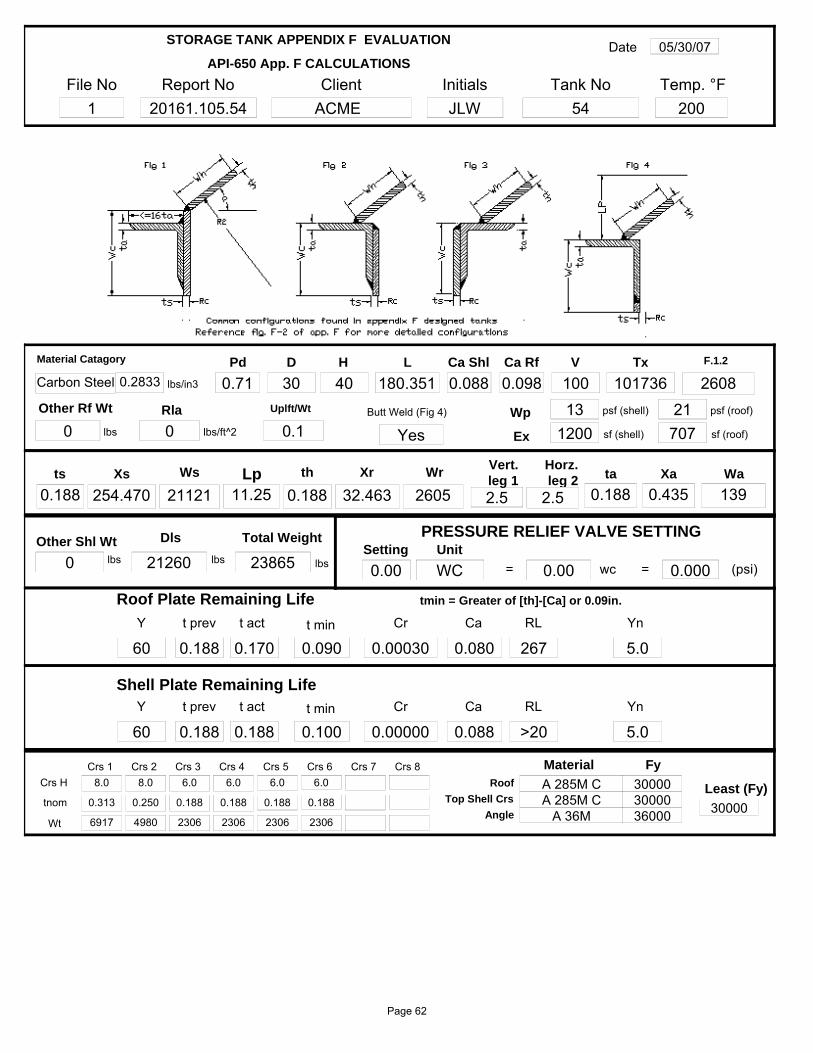
File No1
Report No20161.105.54
InitialsJLW
Client ACME
Tank No54
Date 05/30/07
Temp. °F200
API-650 App. F CALCULATIONS
STORAGE TANK APPENDIX F EVALUATION
Ca Shl
0.088 lbs/in30.2833Tx
101736
Total Weight
23865 lbs
lbs
Other Rf Wt
0
Dls
21260 lbs
Pd
0.71 2608F.1.2V
100
Wp 13 psf (shell)
Ex 1200 sf (shell) 707 sf (roof)
21 psf (roof)
Material Catagory
Carbon Steel
Butt Weld (Fig 4)
Yes
ts
0.188th
0.188 2.5ta
0.188Xa
0.435
D
30H
40
Xs
254.470Ws
21121
L
180.351
11.25Lp Xr
32.463Wr
2605leg 2
2.5 leg 1 Wa
139
Horz.Vert.
PRESSURE RELIEF VALVE SETTING
(psi)0.000=Setting
0.00Unit
wc0.00=WC
Y
60t prev
0.188t act
0.170Cr
0.00030RL
267
Roof Plate Remaining Life
Ca
0.080t min
0.090Yn
5.0
Y
60t prev
0.188t act
0.188Cr
0.00000RL
>20
Shell Plate Remaining LifeCa
0.088t min
0.100Yn
5.0
Ca Rf
0.098
Crs 18.0
Crs 28.0
0.313 0.250
Crs 36.0
Crs 46.0
0.188 0.188
Crs 56.0
Crs 66.0
0.188 0.188
Crs 7 Crs 8Crs H
tnom
6917Wt 4980 2306 2306 2306 2306
0.1Uplft/Wt
0
0
Rla
Other Shl Wt
lbs/ft^2
lbs
Roof
Top Shell Crs
Angle
Fy
300003000036000 30000
Least (Fy)
Material
A 285M CA 285M C
A 36M
tmin = Greater of [th]-[Ca] or 0.09in.
Page 62
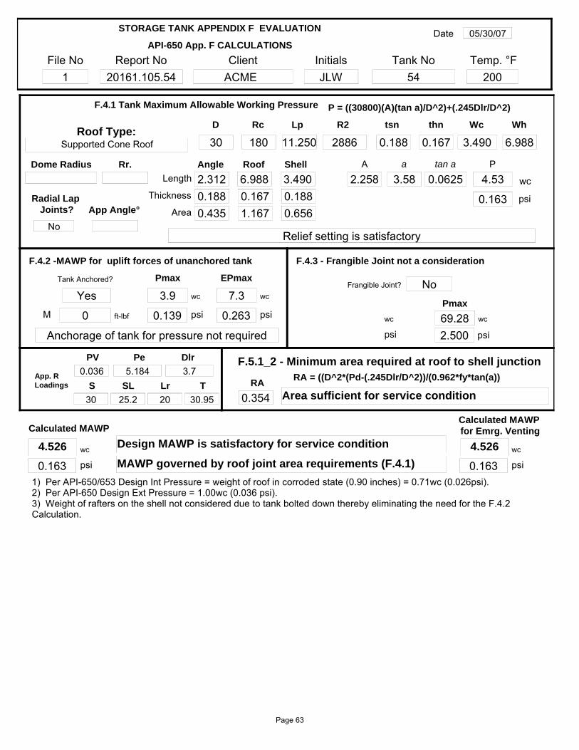
File No1
Report No20161.105.54
InitialsJLW
Client ACME
Tank No54
Date 05/30/07
Temp. °F200
API-650 App. F CALCULATIONS
STORAGE TANK APPENDIX F EVALUATION
1) Per API-650/653 Design Int Pressure = weight of roof in corroded state (0.90 inches) = 0.71wc (0.026psi).2) Per API-650 Design Ext Pressure = 1.00wc (0.036 psi).3) Weight of rafters on the shell not considered due to tank bolted down thereby eliminating the need for the F.4.2 Calculation.
Tank Anchored?
Yes
P
4.53
0.163wc
psi
Relief setting is satisfactory
Rc
180R2
2886tsn
0.188Wh
6.988Wc
3.490
F.4.1 Tank Maximum Allowable Working Pressure
thn
0.167
Length 2.312Thickness 0.188
Roof
6.988
Area 0.435
Angle
0.1671.167
Shell
3.4900.1880.656
A
2.258 3.58tan a
0.0625a
Lp
11.250D
30
P = ((30800)(A)(tan a)/D^2)+(.245Dlr/D^2)
Pmax
3.9 wc
M 0 ft-lbf 0.139 psi wc 69.28 wc
2.500 psipsi
F.4.3 - Frangible Joint not a consideration
Pmax
F.4.2 -MAWP for uplift forces of unanchored tank
Anchorage of tank for pressure not required
Frangible Joint? No
0.354
F.5.1_2 - Minimum area required at roof to shell junction
RAArea sufficient for service condition
Calculated MAWP
Design MAWP is satisfactory for service conditionwc
0.163 psi MAWP governed by roof joint area requirements (F.4.1)
Roof Type:
App Angle°
Supported Cone Roof
Dome Radius
EPmax
7.3 wc
0.263 psi
Calculated MAWP for Emrg. Venting
wc
0.163 psi
Rr.
S
30
PV
0.036Lr
2025.2
Pe
5.184SL
Dlr
3.7T
30.95
App. R Loadings
RA = ((D^2*(Pd-(.245Dlr/D^2))/(0.962*fy*tan(a))
Radial Lap Joints?
No
4.526 4.526
Page 63
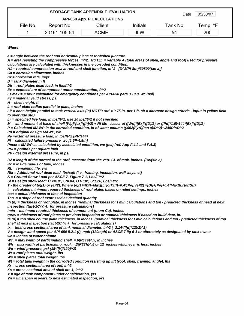
File No1
Report No20161.105.54
InitialsJLW
Client ACME
Tank No54
Date 05/30/07
Temp. °F200
API-650 App. F CALCULATIONS
STORAGE TANK APPENDIX F EVALUATION
Where;
a = angle between the roof and horizontal plane at roof/shell junctureA = area resisting the compressive forces, in^2. NOTE: = variable A (total areas of shell, angle and roof) used for pressure calculations are calculated with thicknesses in the corroded condition.A1 = required compression area at roof and shell junction, in^2 [D^2(Pi-8th)/30800(tan a)]Ca = corrosion allowance, inchesCr = corrosion rate, in/yrD = tank diameter in ftDlr = roof plates dead load, in lbs/ft^2Ex = exposed are of component under consideration, ft^2EPmax = MAWP calculated for emergency conditions per API-650 para 3.10.8, wc (psi)Fy = material yeild stress, psiH = shell height, ftL = roof plate radius parallel to plate, inchesLP = cone height parallel to tank vertical axis (in) NOTE: std = 0.75 in. per 1 ft, alt = alternate design criteria - input in yellow field to over ride std)Lr = specified live load, in lbs/ft^2, use 20 lbs/ft^2 if not specifiedM = wind moment at base of shell [Wp]*[ex]*([h]/2) + Rf Mo =lesser of ([Wp]*[Ex]*([D]/2) or ([Pd]*1.6)*144*[Ex]*([D]/2)P = Calculated MAWP in the corroded condition, in of water column ((.962(FyA)(tan a)/D^2)+.245Dlr/D^2Pd = original design MAWP, wcPe =external pressure load, in lbs/ft^2 (PV*144)Pf = calculated failure pressure, wc [1.6P-4.8th]Pmax = MAWP as calculated by associated condition, wc (psi) (ref. App F.4.2 and F.4.3)PSI = pounds per square inchPV - design external pressure, in psi
R2 = length of the normal to the roof, measure from the vert. CL of tank, inches. (Rc/(sin a)Rc = inside radius of tank, inchesRL = remaining life, yrsRla = Additional roof dead load, lbs/sqft (i.e., framing, insulation, walkways, et)S = Ground Snow Load per ASCE 7, Figure 7-1, Lbs/Ft^2Sl = Design snow load: Ө <=10°, S*0.84, Ө > 10°, S*1.26, Lbs/Ft^2T - the greater of (e)(1) or (e)(2), Where (e)(1)=[Dl]+Max([Lr]or[Sl])+0.4*[Pe], (e)(2) =[Dl]+[Pe]+0.4*Max([Lr]or[Sl])t = calculated minimum required thickness of roof plates bases on relief settings, inches tact = actual thickness at time of inspectionTan a = slope of roof expressed as decimal quantityth (n) = thickness of roof plate, in inches (nominal thickness for t min calculations and tsn - predicted thickness of head at next inspection (tact-2CrYn), for pressure calculations)tmin = minimum required thickness of component (tnom-Ca), inchestprev = thickness of roof plates at previous inspection or nominal thickness if based on build date, in.ts (n) = top shell course plate thickness, in inches. (nominal thickness for t min calculations and tsn - predicted thickness of top shell at next inspection (tact-2CrYn), for pressure calculations)tx = total cross sectional area of tank nominal diameter, in^2 (=3.14*(([d]*12)/2)^2)V = design wind speed per API-650 5.2.1 (f), mph (120mph) or ASCE 7 fig 6-1 or alternately as designated by tank ownerwc = inches of water columnWc. = max width of participating shell, =.6(RcTs)^.5, in inchesWh = max width of participating. roof, =.3(R2Th)^.5 or 12 inches whichever is less, inchesWp = wind pressure, psf (18*([V]/120)^2)Wr = roof plates total weight, lbsWs = shell plates total weight, lbsWt = total tank weight in the corroded condition resisting up lift (roof, shell, framing, angle), lbsXr = cross sectional area of roof, in^2Xs = cross sectional area of shell crs 1, in^2Y = age of tank component under consideration, yrsYn = time span in years to next estimated inspection, yrs
Page 64
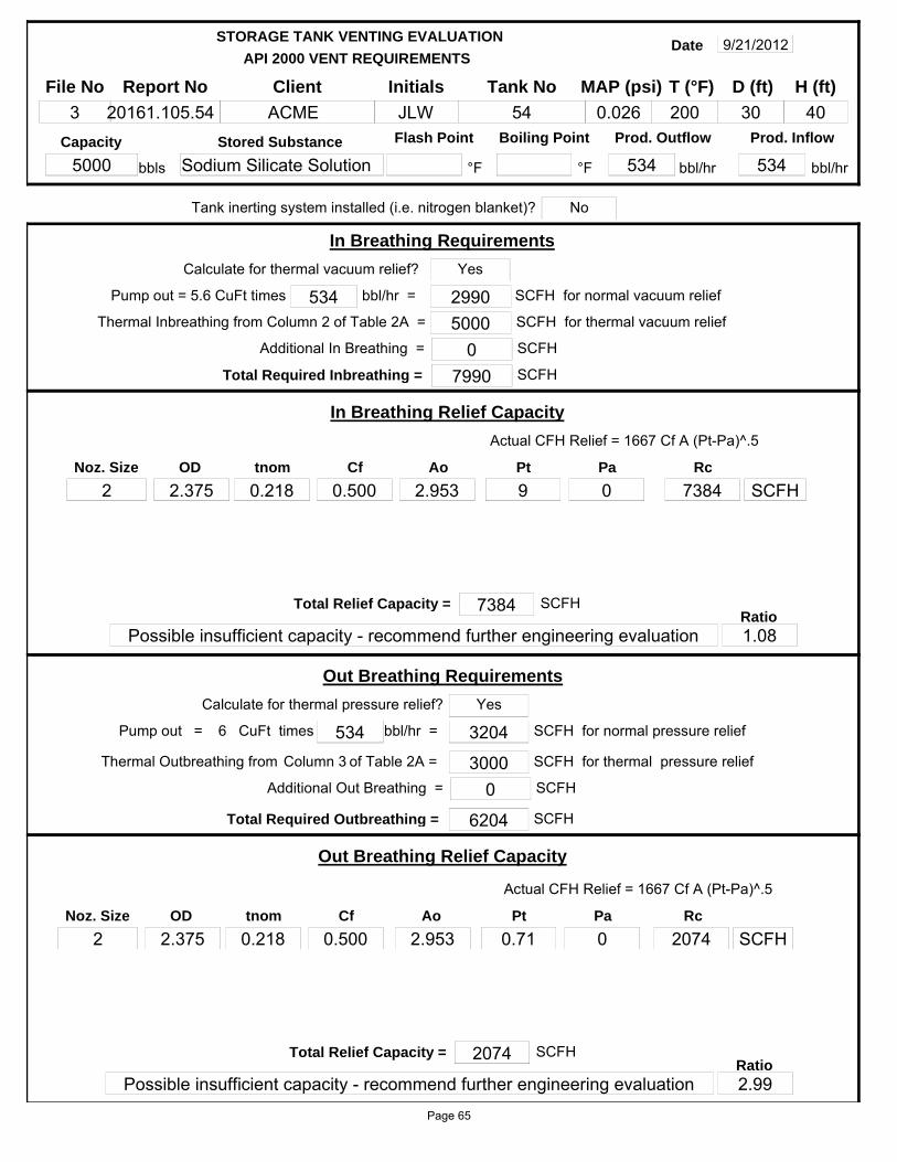
API 2000 VENT REQUIREMENTS
STORAGE TANK VENTING EVALUATION
File No
3Report No
20161.105.54Initials
JLWClient
ACMETank No
54
Date 9/21/2012
MAP (psi)
0.026 30D (ft)
40H (ft)
Flash Point Boiling Point
°F
Prod. Outflow
534 bbl/hr
Prod. Inflow
534 bbl/hr
Capacity
5000Stored Substance
Sodium Silicate Solution °Fbbls
T (°F)
200
bbl/hr = 534
Total Required Inbreathing = 7990
In Breathing Requirements
SCFH
Thermal Inbreathing from Column 2 of Table 2A = 5000 SCFH for thermal vacuum relief2990 SCFH for normal vacuum reliefPump out = 5.6 CuFt times
Calculate for thermal vacuum relief?
of Table 2A = Column 3
Actual CFH Relief = 1667 Cf A (Pt-Pa)^.5
In Breathing Relief Capacity
tnom
0.218OD
2.375Ao
2.953Pt
9Pa
0Rc
7384
Total Relief Capacity = 7384
Possible insufficient capacity - recommend further engineering evaluation
SCFHRatio1.08
bbl/hr = 534
Total Required Outbreathing = 6204
Out Breathing Requirements
SCFH
Thermal Outbreathing from 3000 SCFH for thermal pressure relief
3204 SCFH for normal pressure relief
Actual CFH Relief = 1667 Cf A (Pt-Pa)^.5
Out Breathing Relief Capacity
tnom
0.218OD
2.375Ao
2.953Pt
0.71Pa
0Rc
2074
Total Relief Capacity = 2074
Possible insufficient capacity - recommend further engineering evaluation
SCFHRatio2.99
Calculate for thermal pressure relief?
CuFt times6Pump out =
Yes
Noz. Size
2
Yes
Noz. Size
2
SCFH
SCFH
Tank inerting system installed (i.e. nitrogen blanket)? No
Additional In Breathing = 0 SCFH
Additional Out Breathing = 0 SCFH
Cf
0.500
Cf
0.500
Page 65
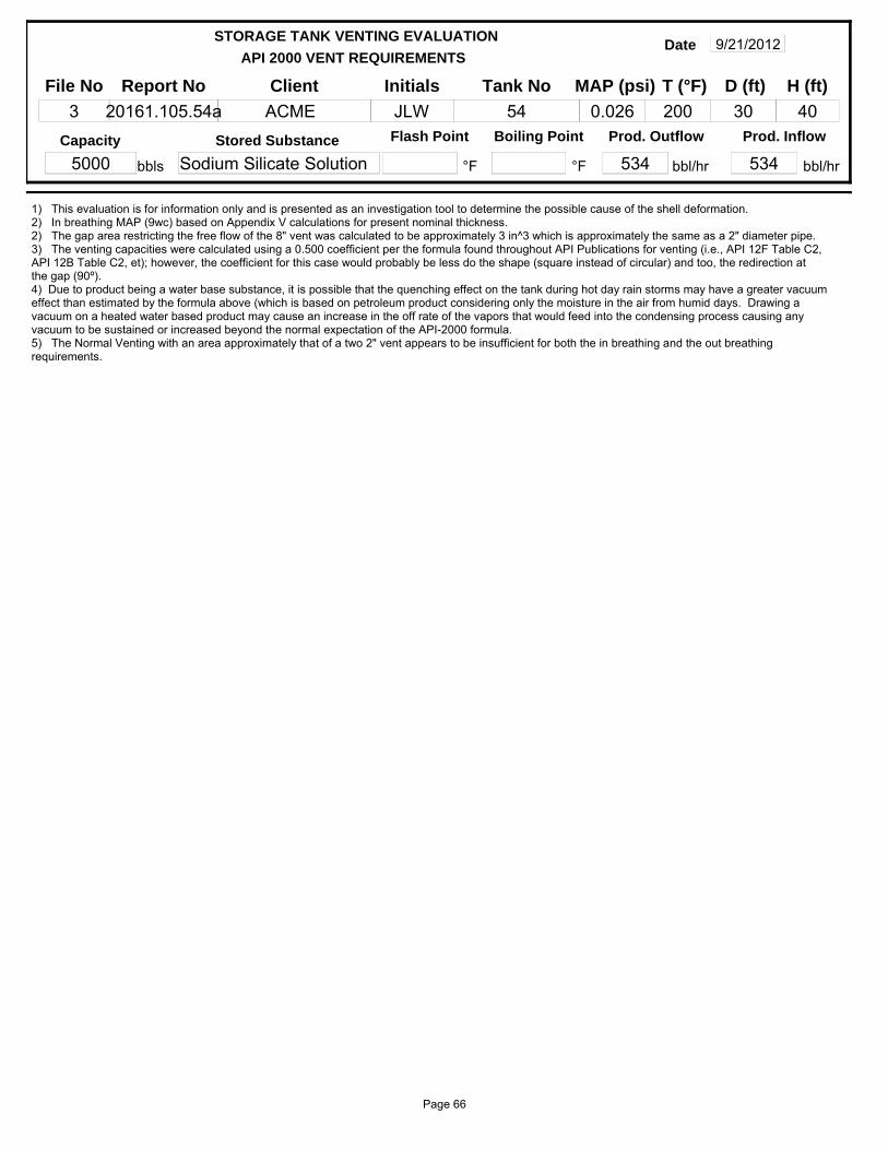
API 2000 VENT REQUIREMENTS
STORAGE TANK VENTING EVALUATION
File No
3Report No
20161.105.54aInitials
JLWClient
ACMETank No
54
Date 9/21/2012
MAP (psi)
0.026 30D (ft)
40H (ft)
Flash Point Boiling Point
°F
Prod. Outflow
534 bbl/hr
Prod. Inflow
534 bbl/hr
Capacity
5000Stored Substance
Sodium Silicate Solution °Fbbls
T (°F)
200
1) This evaluation is for information only and is presented as an investigation tool to determine the possible cause of the shell deformation.2) In breathing MAP (9wc) based on Appendix V calculations for present nominal thickness.2) The gap area restricting the free flow of the 8" vent was calculated to be approximately 3 in^3 which is approximately the same as a 2" diameter pipe.3) The venting capacities were calculated using a 0.500 coefficient per the formula found throughout API Publications for venting (i.e., API 12F Table C2, API 12B Table C2, et); however, the coefficient for this case would probably be less do the shape (square instead of circular) and too, the redirection at the gap (90º).4) Due to product being a water base substance, it is possible that the quenching effect on the tank during hot day rain storms may have a greater vacuum effect than estimated by the formula above (which is based on petroleum product considering only the moisture in the air from humid days. Drawing a vacuum on a heated water based product may cause an increase in the off rate of the vapors that would feed into the condensing process causing any vacuum to be sustained or increased beyond the normal expectation of the API-2000 formula.5) The Normal Venting with an area approximately that of a two 2" vent appears to be insufficient for both the in breathing and the out breathing requirements.
Page 66

API 2000 VENT REQUIREMENTS
STORAGE TANK VENTING EVALUATION
File No
3Report No
20161.105.54Initials
JLWClient
ACMETank No
54
Date 9/21/2012
MAP (psi)
0.026 30D (ft)
40H (ft)
Flash Point Boiling Point
°F
Prod. Outflow
534 bbl/hr
Prod. Inflow
534 bbl/hr
Capacity
5000Stored Substance
Sodium Silicate Solution °Fbbls
T (°F)
200
Tank roof attached with frangible joint? Emergency venting requiredTank subject to fire exposure?
Tank bottom subject to fire exposure? (i.e., elevated tank on legs)
Q
14090000A
2827.4F
1L T M
SCFH
H limit (ft)
Venting Requirements calculated SCFH Relief = 3.091*(QF/L)*(T/M)^.5
30 2827Wetted Area
Ft^2 SCFH
Venting requirements may be determined by either of the following methods. Evaluation 1 is a general estimate where Evaluation 2 is a more accurate evaluation
Evaluation 1
Evaluation 2
Venting Requirements SCFH Relief = 1107*F*A^.82
742000 SCFH
Venting Requirements from Table 3A
2827Wetted Area
Ft^2
Venting Requirements
Venting Requirements
Actual CFH Relief = 1667 Cf A (Pt-Pa)^.5
Emergency Relief Capacity
tnom
0.250OD
24Ao
433.737Pt
4.526Pa
0RC
769112
Total Relief Capacity = 774348
Sufficient capacity for design conditions
SCFHRatio0.96
SCFHVenting Required = 742000
(Emerg. + Normal)
0 % Bttm exp
(Table 3A)
(Equation 2A)
Emergency Venting Requirements for Vertical Tanks
F Factor
1
Yes
No
No
Venting Requirements
Calc Eq. 2A
Noz. Size
24 SCFH
1) This evaluation is for information only and is presented as an investigation tool to determine the possible cause of the shell deformation.
4.526 0Cf
0.500
PaPt
Page 67
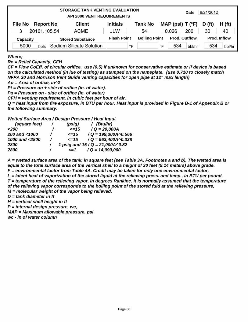
API 2000 VENT REQUIREMENTS
STORAGE TANK VENTING EVALUATION
File No
3Report No
20161.105.54Initials
JLWClient
ACMETank No
54
Date 9/21/2012
MAP (psi)
0.026 30D (ft)
40H (ft)
Flash Point Boiling Point
°F
Prod. Outflow
534 bbl/hr
Prod. Inflow
534 bbl/hr
Capacity
5000Stored Substance
Sodium Silicate Solution °Fbbls
T (°F)
200
Where;Rc = Relief Capacity, CFHCF = Flow CoEff. of circular orifice. use (0.5) if unknown for conservative estimate or if device is based on the calculated method (in lue of testing) as stamped on the nameplate. (use 0.710 to closely match NFPA 30 and Morrison Vent Guide venting capacities for open pipe at 12" max length)Ao = Area of orifice, in^2Pt = Pressure on + side of orifice (in. of water). Pa = Pressure on - side of orifice (in. of water)CFH = venting requirement, in cubic feet per hour of air,Q = heat input from fire exposure, in BTU per hour. Heat input is provided in Figure B-1 of Appendix B or the following summary:
Wetted Surface Area / Design Pressure / Heat Input (square feet) / (psig) / (Btu/hr)<200 / <=15 / Q = 20,000A200 and <1000 / <=15 / Q = 199,300A^0.5661000 and <2800 / <=15 / Q = 963,400A^0.3382800 / 1 psig and 15 / Q = 21,000A^0.822800 / <=1 / Q = 14,090,000
A = wetted surface area of the tank, in square feet (see Table 3A, Footnotes a and b), The wetted area is equal to the total surface area of the vertical shell to a height of 30 feet (9.14 meters) above grade.F = environmental factor from Table 4A. Credit may be taken for only one environmental factor,L = latent heat of vaporization of the stored liquid at the relieving press. and temp., in BTU per pound,T = temperature of the relieving vapor, in degrees Rankine. It is normally assumed that the temperatureof the relieving vapor corresponds to the boiling point of the stored fuid at the relieving pressure,M = molecular weight of the vapor being relieved.D = tank diameter in ftH = vertical shell height in ftP = internal design pressure, wc,MAP = Maximum allowable pressure, psiwc - in of water column
Page 68

File No1
Report No20161.105.54
InitialsJLW
Client ACME
Tank No54
Date 9/21/2012
Temp. °F200
PARTIAL VACUUM CALCULATIONS
STORAGE TANK API-650 APPENDIX V EVALUATION
Supported Cone
tnom0.188
Pressure9.00
wc9.00=
Design External Pressure
psi0.32=
oz5.20=
RoofShell
Angle0.1880.188
Sds200002000023200
Ca0.0000.000
tmin0.1880.188
WC
MaterialA 285M CA 285M C
A 36MUnit
S
30Dl
7.7Lr
20X
30Pr
66.46Pe
46.786 290000000a°
3.576D
30tr
0.2833
wt Length 2.5ta
0.188leg 2
2.5 leg 1
Top Angle Horz.Vert.
Roof Evaluation Not Applicable
Roof Type:Angle Attachment. Butt Weld (Fig 4) YesMaterial Catagory
CS/Crom. Stl
E
(PCI)
Ht
8.000H
8te
0.313Hts 107.869
Unstiffened Shell
Crs 1
Crs 2
Crs 3
Crs 4
Crs 5
Crs 6
14.0318 0.250
21.4596 0.188
21.4596 0.188
21.4596 0.188
21.4596 0.188
ts 0.187cr 1.120
Fy 30000
W 30.945Ps 49.659
Sat
Trans. Height, ft
Wind Press., psf
Adj, Pr, psf
Shell tmin, in
Buckling Crit., >.19
Yeild Strength
Shell thickness satisfactory for existing conditions
cr results:
3.576
11.25
30
80.000
Page 69
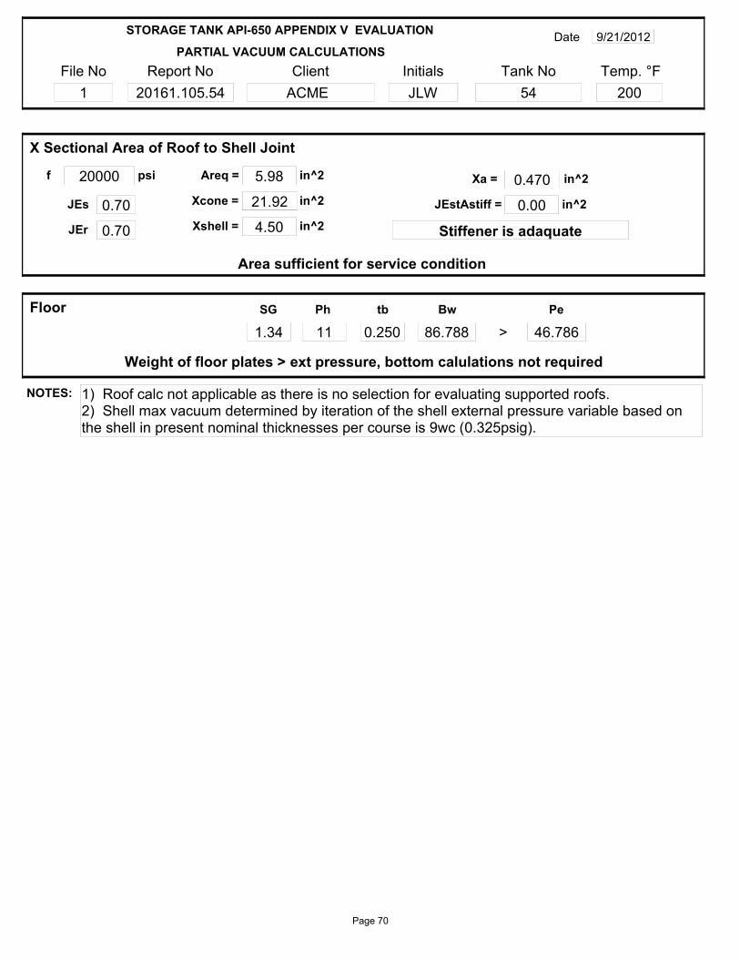
File No1
Report No20161.105.54
InitialsJLW
Client ACME
Tank No54
Date 9/21/2012
Temp. °F200
PARTIAL VACUUM CALCULATIONS
STORAGE TANK API-650 APPENDIX V EVALUATION
Areq = 5.98f 20000 in^2psi
21.92 in^2
Xshell = 4.50 in^20.70JEs
0.70JEr
JEstAstiff = 0.00 in^2
Area sufficient for service condition
Xa = 0.470
Stiffener is adaquate
X Sectional Area of Roof to Shell Joint
Xcone =
in^2
tb
0.250SG
1.34Ph
11Bw
86.788
Floor
Weight of floor plates > ext pressure, bottom calulations not required
Pe
46.786>
NOTES: 1) Roof calc not applicable as there is no selection for evaluating supported roofs.2) Shell max vacuum determined by iteration of the shell external pressure variable based on the shell in present nominal thicknesses per course is 9wc (0.325psig).
Page 70
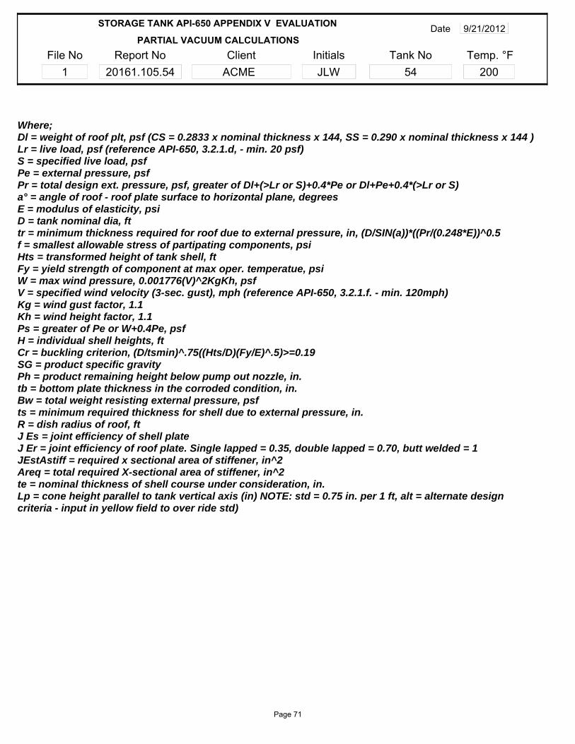
File No1
Report No20161.105.54
InitialsJLW
Client ACME
Tank No54
Date 9/21/2012
Temp. °F200
PARTIAL VACUUM CALCULATIONS
STORAGE TANK API-650 APPENDIX V EVALUATION
Where;Dl = weight of roof plt, psf (CS = 0.2833 x nominal thickness x 144, SS = 0.290 x nominal thickness x 144 )Lr = live load, psf (reference API-650, 3.2.1.d, - min. 20 psf)S = specified live load, psfPe = external pressure, psfPr = total design ext. pressure, psf, greater of Dl+(>Lr or S)+0.4*Pe or Dl+Pe+0.4*(>Lr or S)a° = angle of roof - roof plate surface to horizontal plane, degreesE = modulus of elasticity, psiD = tank nominal dia, fttr = minimum thickness required for roof due to external pressure, in, (D/SIN(a))*((Pr/(0.248*E))^0.5f = smallest allowable stress of partipating components, psiHts = transformed height of tank shell, ftFy = yield strength of component at max oper. temperatue, psiW = max wind pressure, 0.001776(V)^2KgKh, psfV = specified wind velocity (3-sec. gust), mph (reference API-650, 3.2.1.f. - min. 120mph)Kg = wind gust factor, 1.1Kh = wind height factor, 1.1Ps = greater of Pe or W+0.4Pe, psfH = individual shell heights, ftCr = buckling criterion, (D/tsmin)^.75((Hts/D)(Fy/E)^.5)>=0.19SG = product specific gravityPh = product remaining height below pump out nozzle, in.tb = bottom plate thickness in the corroded condition, in.Bw = total weight resisting external pressure, psfts = minimum required thickness for shell due to external pressure, in.R = dish radius of roof, ftJ Es = joint efficiency of shell plateJ Er = joint efficiency of roof plate. Single lapped = 0.35, double lapped = 0.70, butt welded = 1JEstAstiff = required x sectional area of stiffener, in^2Areq = total required X-sectional area of stiffener, in^2te = nominal thickness of shell course under consideration, in.Lp = cone height parallel to tank vertical axis (in) NOTE: std = 0.75 in. per 1 ft, alt = alternate design criteria - input in yellow field to over ride std)
Page 71

APPENDIX G
1) UT Calabration Report
2) NDE Tech Certification
3) API Inspector Certification
NDE Records and Certifications
Page 72
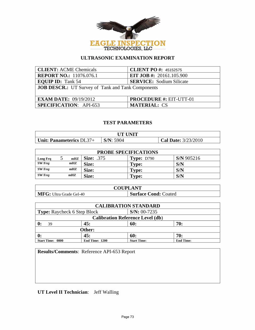
ULTRASONIC EXAMINATION REPORT
CLIENT: ACME Chemicals CLIENT PO #: 45152575 REPORT NO.: 11076.076.1 EIT JOB #: 20161.105.900 EQUIP ID: Tank 54 SERVICE: Sodium Silicate JOB DESCR.: UT Survey of Tank and Tank Components
EXAM DATE: 09/19/2012 PROCEDURE #: EIT-UTT-01 SPECIFICATION: API-653 MATERIAL: CS
TEST PARAMETERS
UT UNIT Unit: Panameterics DL37+ S/N: 5904 Cal Date: 3/23/2010
PROBE SPECIFICATIONS Long Frq 5 mHZ Size: .375 Type: D790 S/N 905216 SW Frq: mHZ Size: Type: S/NSW Frq: mHZ Size: Type: S/NSW Frq: mHZ Size: Type: S/N
COUPLANT MFG: Ultra Grade Gel-40 Surface Cond: Coated
CALIBRATION STANDARD Type: Raycheck 6 Step Block S/N: 00-7235
Calibration Reference Level (db) 0: 39 45: 60: 70:
Other: 0: 45: 60: 70:Start Time: 0800 End Time: 1200 Start Time: End Time:
Results/Comments: Reference API-653 Report
UT Level II Technician: Jeff Walling
Page 73


Page 75

APPENDIX H
API STANDARD 653 (FOURTH EDITION, MARCH 2009 ADD 2)
API STANDARD 650 (ELEVENTH EDITION, JUNE 2007 ADD 3)
API RECOMMENDED PRACTICE 575 SECOND EDITION, MAY 2005
API STANDARD 2000 FIFTH EDITION, APRIL 1998
API SPECIFICATION 12F ELEVENTH EDITION, NOVEMBER 1, 1994
NFPA 30 (2003 edition)
UL 142 DECEMBER 28, 2006
ASNT SNT-TC-1A 2011 EDITION
References
Page 76