acknowledgementsrepository-tnmgrmu.ac.in/2911/7/240502313nupurarathi.pdf · more beneficial...
TRANSCRIPT


ACKNOWLEDGEMENTS
At this juncture I am honour bound to express my immense gratitude to
everyone who have helped me through this journey.
Firstly I extend my gratefulness to my very respected and beloved
professor, Dr.N.R.Krishnaswamy, M.D.S., M.Ortho RCS.(Edin), Diplomat of
Indian National of Orthodontics, Professor and Head, Department of
Orthodontics, Ragas Dental College and Hospital, Chennai. It is indeed my
good fortune to have had the opportunity to do my post graduation under his
able guidance. Besides being a constant source of encouragement, he has
inspired me to perform better not only in academics but also in life. I thank
him for having taken interest in my study and providing his valuable insight.
I am indebted to express my solemn gratitude to my respected
professor Dr.S.Venkateswaran, M.D.S.,D.N.B (Ortho), for being a pillar of
support all through my academics.
I would like to thank my professor, Dr. Ashwin George, M.D.S.,D.N.B
(Ortho) to have helped me tune myself to the changing environment in our
profession.
Words seem insignificant to express my deep sense of gratitude to my
post graduate teacher and guide, Dr.Rekha Bharadwaj, M.D.S.,(Reader),
Department of Orthodontics, Ragas Dental College and Hospital, Chennai,
for her valuable guidance, suggestions, tireless pursuit for perfection and her

immense patience towards my amateur mistakes. I thank her for the keen
surveillance of the minute details throughout this dissertation. Without the
help that she has conferred upon me this dissertation would not have come
true.
My sincere thanks to Prof.Mr.KANAGARAJ, Chairman &
Dr.S.RAMACHANDRAN, Principal, Ragas Dental College for providing me
with an opportunity to utilize the facilities available in this institution in order
to conduct this study.
I greatly acknowledge Dr. SHAHUL (Professor), Dr. ANAND
(Reader) Dr. JAYAKUMAR (Reader), Dr. SHAKEEL (Reader),
Dr. SHOBANA, Dr. PRABHU, and Dr. BIJU TOM, Dr. KAVITHA.
S.IYER (senior lecturers) for their support, enthusiasm & professional
assistance throughout my post graduate course.
My heartfelt thanks to my wonderful batch mates Dr. Ashwin,
Dr. Manikandan, Dr. Deepak, Dr. Siva Subramanian, Dr. Sakthi,
Dr. Ravanth, who were cheerfully available at all times to help me. I wish
them a successful career ahead.
I also extend my gratitude to my juniors Dr.Femin, Dr.Murali,
Dr.Vishal, Dr.Gayathri, Dr.Manali, Dr.Vikram, Dr.Regina and
Dr.Saptharishi, Dr.Anselm, Dr.Avdesh, Dr.Divya, Dr.Jayakrishna,
Dr.Karthik, Dr.Mercy, Dr.Piradhiba, Dr.Shrabani, for all their support.

I thank Mr.Ravanan, for helping me with the statistical analysis for the
study. I am extremely thankful to Versetia Technologies for conducting the
finite element analysis for my study.
I extend my gratitude to Mr.Ashok and Mr.Rajendran for helping with
the photographs of the study.
I would like to thank Sisters Lakshmi, Rathi, Kanaka, & Azeena,
Ms. Banupriya, Ms.Divya, and attender Mr. Baskar, Mr. Mani for their
co-operation and help during my Post-Graduate course.
My heartfelt thanks to my wonderful grandparents,
Prof. Dr.C.A.Perumal and Mrs.Jayalakshmi Perumal, who have been my
pillar of support and an eternal source of energy in every endeavour of mine.
I would also like to thank my parents, Dr.K.Gurunath and Dr.Vimala
Gurunath, and my sister, G.Rohini for their love, understanding and support.
Above all, I am thankful to God almighty, to have given me the
strength to pursue this course and also to have given all these wonderful
people in my life.

CONTENTS
S.NO
TITLE
PAGE NO.
1
INTRODUCTION
1
2
REVIEW OF LITERATURE
6
3
MATERIALS AND METHODS
35
4
RESULTS
44
5
DISCUSSION
46
6
SUMMARY AND CONCLUSION
56
7
BIBLIOGRAPHY
57
ABSTRACT
Biomechanics of space closure is an integral stage of orthodontic
treatment wherein, the understanding of the mechanical system utilized for
closing extraction space is critical. Loop mechanics is a more convenient method
of space closure in that a known force system is delivered to the teeth and no
friction involved. Two popular loops used for en-masse space closure are Double
Keyhole loop and Continuous T-loop. However, they are biomechanical
properties and their retraction efficiency has not been studied previously in
literature.
Therefore, the present study aimed to involve the moment-force ratio of
Double Keyhole loop and Continuous T-loop for en-masse space closure with
two different methods of activation using a finite element method. The resultant
stress, displacement and moment-force ratio was calculated for two loops at 0, 15
and 30 degree gable bends at 1 mm activation using cinch back and ligature tie.
Results show that there was no significant difference in the overall stress
distribution and displacement of the teeth with both the loops. Nevertheless, the
moment-force ratio achieved a desirable ratio of 8-10 and increased with increase
in gable bend with both Double Keyhole loop and Continuous T-loop. Therefore
the study conclusively proves that both the loops, though different in design and
morphology was equally efficient for en-masse space closure producing bodily or
translatory tooth movement without anchor loss in maximum anchorage cases.
Keywords :- Finite element analysis, Double keyhole loop (DKHL), Continuous
T-loop (T-loop), moment-force ratio.
Introduction
1
INTRODUCTION
Biomechanics of Space Closure poses a great challenge to an
orthodontist and is the integral stage of orthodontic treatment wherein, the
understanding of the mechanical system utilized for closing extraction space
is critical. This can be done depending on the type of tooth movement needed
and the anchorage requirements. Anchorage control is delivery of differential
force system to the anchor tooth and is determined by applying unequal
moment – force ratios to each unit.
Tooth movement can be accomplished with optimum forces and the
rate of tooth movement increases with force upto a point after which the tooth
movement decreases or ceases with increased force levels due to undermining
resorption and necrosis of the supporting periodontal tissues as suggested by
Storey and Smith65,74
.
Schwartz et al stated that optimal force levels are required to achieve
predictable tooth movement because forces below this level cause no tissue
response in the periodontal ligament whereas excessive force leads to tissue
necrosis, preventing tooth movement57, 74
.
The current concept of optimal force is based on the hypothesis that a
force of certain magnitude and temporal characteristics (continuous Vs
intermittent, constant Vs declining etc) would be capable of producing a
maximum rate of tooth movement without tissue damage74
. Therefore, the
Introduction
2
preferred space closure mechanism must be the one that is easy to fabricate
with minimal activation, cause least discomfort to the patient and finally
produce a predictable space closure43
.
Hence, treatment mechanics should produce an dentition that are in
ideal positions with roots uprighted and stable on the basal bone. In majority
of cases, this can be accomplished with bodily/translatory type of tooth
movement.
Space closure can be accomplished using either friction or
frictionless/loop mechanics. Friction mechanics causes binding of the
archwire, thereby taxing the anchorage, increasing the force levels, resulting
in unwanted tooth movement25
.
In this regard, loop mechanics is more beneficial in that a known force
system is delivered to the teeth and spaces are closed with the help of loops
with forces and couples built into it. Moreover, the loops incorporated in the
arch wire increases the flexibility and springiness thereby producing optimal
force for different types of tooth movement8, 10
.
Space closure can be done either as two step retraction where the
canines are distalized first followed by anterior retraction that is supposed to
be less detrimental to anchorage. However, the treatment time is prolonged.
On the contrary, an en-mass /one step retraction is more beneficial in terms of

Introduction
3
duration of treatment. Nevertheless it is still debated if a two-step retraction is
more beneficial compared to en-masse retraction for preserving anchorage.
There are several loops in the literature that can be used for space
closure.T-loop is one of the most common loop for producing predictable
space closure. It was developed by Burstone et al for individual canine
retraction using TMA wires10
. The literature is replete for segmental T-loop
biomechanics when compared to continuous T-loop biomechanics.
Double keyhole loop was introduced by John Parker55
and has the
following specific advantages:-
1. Allows the luxurious use of one set of arch wire for entire space
closure.
2. Allows a reasonably happy medium between severe tipping and
sliding mechanics.
3. Allows the operator to select how the space will be closed
depending on anchorage consideration.
4. Control of canine position.
Incorporation of two loops makes the arch wire more flexible for
optimum force delivery. It acts like a stress braker in the canine region. To
satisfy the principles of gnathology, the in-built canine tip in Roth prescription
is 13° and if the force levels are not at an optimum, this can alter the moment–
force ratio, cause the canine root to be displaced into the cortical plate, thereby

Introduction
4
taxing the anchorage. In this regard Roth suggested that double keyhole loop
particularly works well with his prescription, aiding in excellent control of
canine position and rotation. There is no existing literature available on the
biomechanics of Double key hole loop.
Some of the important factors governing the loop mechanics are the
moment-force ratio and the load deflection rate. The moment-force ratio
determines the center of rotation of a tooth or segment of teeth, thus allowing
translation, tipping or root movement46
.
A preactivation or gable bends is frequently incorporated into the loop
configuration to control the centers of rotation through an appropriate
moment-force (M/F) ratio, thereby preventing uncontrolled tipping of the
teeth64
.
Conveniently most of the loops are activated by cinching the wire
distal of the first or second molar, there by activating the loop. As the loops
close, the teeth come together, closing the space. However, the disadvantage
includes difficulty in accessibility and patient discomfort. A different
activation method was suggested by Suzuki wherein the loops are opened for
activation and then a stainless steel ligature is used to ligate the distal loop to
the hook of the first or second molar tube, with sufficient tension to keep the
loops open. As the loops tend to close, the ligature will exert force on the
molar tube and the teeth will come together3. Nevertheless, this method of
activation can vary the point of force application and center of resistance

Introduction
5
hence the moment-force ratio. Therefore, the response of the teeth and
assessing the type of stress distribution in the supporting tissue and moment-
force ratio with different methods of activation is essential for assessing the
3D control of teeth during space closure.
Various methods have been used to study the force generated and
stress distribution in the periodontium. However, the finite element analysis
is a
non-invasive technique, in which the object of various shapes of materials of
non homogenous nature can be studied three dimensionally. It provides a
quantitative data that increases the understanding of the physiologic reactions
that occur after force application and may yield an improved understanding of
the reaction and interactions of individual tissues. Thus the actual stress
experienced can be measured at any point of force application71
.
To the best of our knowledge, there has been no study that has
evaluated the biomechanical response of Double keyhole loop and T-loop on
a continuous wire with different methods of activation.
Aim :- The present study was done to evaluate the stress distribution
and moment-force ratio of Double Keyhole loop and T-loop with two
different methods of activation ( Cinching and Ligature-tie) at different
degrees of gable bend using Finite Element Analysis.
Review of Literature
6
REVIEW OF LITERATURE
Categorized as follows:
Biomechanics
Loop mechanics.
Finite element analysis.
BIOMECHANICS
Burstone & Pryputniewicz (1980)9 used laser holography to study the
three dimensional tooth displacements as it offers an accurate, noninvasive
approach to determine tooth movement and designed an in-vitro study to establish
the force system required on the crown of maxillary incisor which would produce
different centers of rotation for lingual tipping, translation, and root movement
and found that when force is applied at bracket level the center of resistance was at
a point one-third of the distance from the alveolar crest to the apex.
Smith & Burstone (1984)52
studied the relationships between forces
systems and center of rotation in relation to center of resistance to produce desired
tooth movement and their clinical relevance thus determining the moment-force
ratios which produces translation (bodily movement), rotation, tipping and root

Review of Literature
7
movement. Since most forces are applied at the bracket, it is necessary to compute
equivalent force at the center of resistance in order to predict tooth movement.
Kusy and Tulloch (1986)53
compared the Force systems at the
center of resistance for the conventional fixed appliance and for two special
clinical situations in which force systems were delivered at the tooth crown - a
single lateral force and a lateral force complemented by a counteracting couple
and determined that although the force systems that result at the bracket and at
the center of resistance are equivalent, the concept of moment/force ratios at the
bracket can only be reestablished by considering the net moment/net force ratios
at the center of resistance.
Vanden Bulcke , Burstone et al (1986)70
studied the location of the
centers of resistance for various symmetryic units of the anterior maxillary
dentition for a lingually directed force in two dry human skulls using a laser
reflection technique and determined that the center of resistance location shifted
apically as the number of dental units (2, 4 & 6) increased. The greatest shift
occurred in the six- tooth unit, but increasing the magnitude offeree applied to the
units had little effect on the location of center of resistance.
Kazuo Tanne, Koeing & Burstone et al (1988)27
investigated the
relationship between moment to force (M/F) ratios and the centers of rotation using
finite element method for an upper central incisor and found that the center of
Review of Literature
8
resistance was located at 0.24 times the root length measured apical to the level of
alveolar crest.
Pedersen E, Isidor.F, Gjessing.P et al ( 1991)41
using human autopsy
material studied the location of center of resistance of various consolidated units of
maxillary anterior teethand found that when horizontal forces were applied the CR
for the two- and six-tooth units was located approximately 6.5 mm apical to the
bracket position compared to four-tooth unit 5.0 mm. Applying vertical forces CR
was located about 13.0 mm posterior to the bracket position for the two- and
four-tooth unit and incorporation of the canines into the incisor segment resulted
in a distal shift of CR of 6 mm. CR for the six anterior teeth was, thus, located on
a line 3 mm behind the distal surface of the canines.
Demetrios. J (1998)15
studied the forces and moments produced by a
straight portion of an archwire and were transferred from the brackets to the center
of resistance to compare the force system at the brackets to the force system at
the center of resistance and to assess whether bracket geometry can be applied to
predict initial tooth movement. Concluded that the force systems developed by an
ideal arch cannot be used directly to estimate tooth movement they should be first
transferred to the center of resistance of the teeth and the force systems at the
center of resistance may differ significantly from the force systems at the brackets.
Review of Literature
9
Kobayashi&Yoshida et al (2001)34
this study was designed to locate the
centres of restistance of two, four and six anterior teeth during retraction in two
human subjects by measuring the retraction forces applied at different levels by
means of a device for displacement measurement using magnetic sensors and
magnets. Clinically this finding indicates that translation can be achieved with a
smaller amount of moment-to-force ratio in en mass retraction and also indicate
thai the location of the centre of resistance of the anterior segment during retraction
may depend on the palatal alveolar bone height, rather than on the labial alveolar
bone height. correlation exists between the palatal alveolar bone height and the
moment-to-force ratio needed for any orthodontically programmed tooth movement
such as controlled tipping, translation, and root movement during anterior retraction.
Heo , Nalim & Back (2007)69
compared theamount of anchorage loss of
the maxillary posterior teeth and amount of retraction of the maxillary anterior
teeth between en masse retraction and two-step retraction of the anterior teeth. No
significant differences existed in the degree of anchorage loss of the upper posterior
teeth and the amount of retraction of the upper anterior teeth associated with en
masse retraction and two-step retraction of the anterior teeth.When choosing
retraction mechanics, it is necessary to consider additional aspects such as the
inclination and vertical position of the anterior teeth rather than anchorage loss.
Review of Literature
10
Yoshiyuki Koga, Noriaki Yoshida et al (2007)58
determined the location
of center of resistance and compared the relationship between height of retraction
force on power arm and movement of anterior teeth during sliding mechanics
retraction and found that controlled crown-lingual tipping and controlled crown-
labial movement can be achieved by attaching a power-arm length that is lower or
higher than the level of center of resistance, respectively and bodily movement is
achieved by attaching a power-arm length which is at the same level of the center of
resistance.
Jeong GM, Sung SJ et al (2009)19
found the center of resistance of the 4
maxillary anterior teeth, 6 maxillary anterior teeth, and the full maxillary
dentition at 13.5 mm apical and 12.0 mrn posterior, 13.5 mm apical and 14.0 mm
posterior, and 11.0 mm apical and 26.5 mm posterior to the incisal edge of the
upper central incisor, respectively using 3-dimensional finite element analysis.
Masaru Kobayashi, Noriaki Yoshida et al ( 2009)34
determined the
optimal loading conditions such as height of retraction force on the power arm
and its position on the archwire in sliding mechanics during en-masse space
closure. They concluded that the power arm at the level of 0 mm (bracket slot
level), uncontrolled lingual crown tipping of the incisor occurred. At a height of
5.5 mm, bodily movement was produced and the archwire was less deformed.
When the power arm height exceeded 5.5 mm, the anterior segment of the
Review of Literature
11
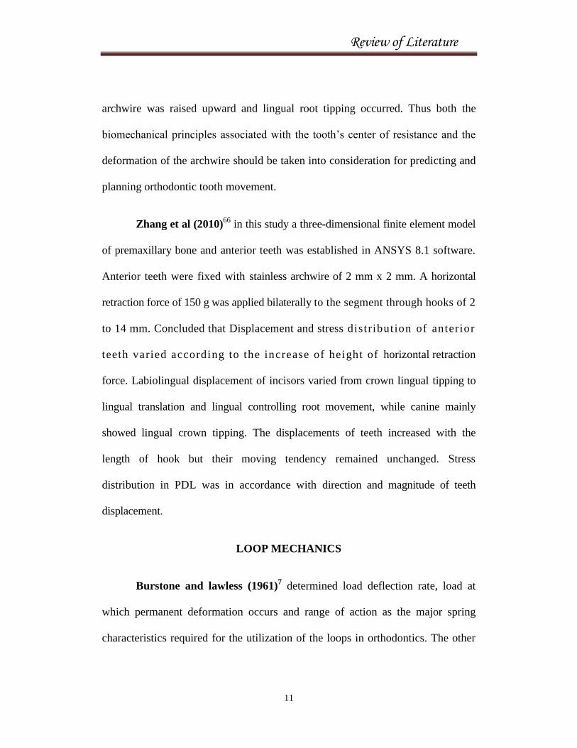
archwire was raised upward and lingual root tipping occurred. Thus both the
biomechanical principles associated with the tooth’s center of resistance and the
deformation of the archwire should be taken into consideration for predicting and
planning orthodontic tooth movement.
Zhang et al (2010)66
in this study a three-dimensional finite element model
of premaxillary bone and anterior teeth was established in ANSYS 8.1 software.
Anterior teeth were fixed with stainless archwire of 2 mm x 2 mm. A horizontal
retraction force of 150 g was applied bilaterally to the segment through hooks of 2
to 14 mm. Concluded that Displacement and stress distribution of anterior
teeth varied according to the increase of height of horizontal retraction
force. Labiolingual displacement of incisors varied from crown lingual tipping to
lingual translation and lingual controlling root movement, while canine mainly
showed lingual crown tipping. The displacements of teeth increased with the
length of hook but their moving tendency remained unchanged. Stress
distribution in PDL was in accordance with direction and magnitude of teeth
displacement.
LOOP MECHANICS
Burstone and lawless (1961)7 determined load deflection rate, load at
which permanent deformation occurs and range of action as the major spring
characteristics required for the utilization of the loops in orthodontics. The other

Review of Literature
12
factors considered in spring design are mechanical properties (modulus of
elasticity), cross section of the wire, its configuration and spring activation. Thus
the springs with low load force deflection rate and high working range of action
delivers more constant force during unloading and can produce an uniform
physiologic tooth movement.
Booth (1971)4 studied the effects on the spring characteristics of a steel
closing loop depending on the wire size, design of the loop, inter-bracket span and
concluded that changing the size of the wire produces the largest changes in
characteristics but the amount of wire incorporated in loop is also important.
Spiro J. Chaconas & Angelo A. Caputo et al (1974)61
compared closed
vertical loop , closed vertical loop with helix , double closed vertical loops with
helix sectional and squashed loop determining the effects of wire size, loop
configuration and gabling on canine-retraction springs and concluded that
increased activation forces were produced when wire size was increased, whereas
gable angle had varying effects upon activation force, depending on the loop
configuration.
Burstone & Koenig et al (1976)8 studied the factors influencing the
moment force ratio in a spring design used for canine and anterior tooth retraction
to optimize spring design and avoid undesirable side effects. They concluded that
increasing loop length, additional length of wire incorporated at loop apex and

Review of Literature
13
angulation of loop legs (if the legs is bent facing towards the apex) the m/f ratio
increases, where as increasing the horizontal length of loop decreases the
moment-force ratio. Placement of the loop: a centered loop produces equal
moment force ratio on either side of the loop, an off centered placement would
generate unequal moments.
Burstone et al (1982)10
has incorporated certain design features into
retraction springs to optimize the force system depending on the material used
(beta-titanium), incorporation of additional wire that is placed into a loop,
centricity of the loop which affects the rate of change of moment-force ratio in
alpha and beta positions and large inter-attachment distance between the auxiliary
tube on the first molar and the vertical tube of the canine allows sufficient space
for the large activations required. In addition, it adds to the accuracy of
determining the force system, since small errors in the shape or geometry of the
spring will not radically change the forces produced.
S.J.Chaconas, A. A. Caupto et al (1989)62
compared three contraction
archwires double delta , contraction torquing arch and contraction torquing utility
archwire and the activation studied were intrusion, retraction and torque. They
indicated that in cases of deepening of bite the double delta archwire would
produce a lingual crown tipping and possibly extrusion of the incisors during
retraction. However if a deep overbite exists prior to anterior tooth consolidation,

Review of Literature
14
the contraction torquing or contraction torquing utility archwires should be used
since they show to produce the most effective lingual root torquing during incisor
retraction.
Faulkner & Lipsett et al (1991)36
studied the limitation of a standard
vertical loop and redesigned it by drastically increasing the use of wire, which
allows larger total activation and considerable preactivation of the appliance.
Thus , incorporating helices to the apex and lateral sides of the loop can
effectively increase the amount of wire being bent and if proper gabling
(preactivation) is coupled to the design with the helices, it will produce
considerably higher moments and M/F ratios compared to the standard loop.
Roth. H. Ronald (1991)55
discussed about double key hole loop retraction
wire in the chapter treatment mechanics for the straight wire appliance. Double
key-hole loop, introduced by John Parker has the following specific advantages.
1. Allows the operator the luxury of complete space closure with one set of arch
wire.
2. Allows a reasonably happy medium between severe tipping and sliding
mechanics.
3. Allows the operator to select how the space will be closed depending on
anchorage considerations.
4. Good control of canine rotation during space closure.
Review of Literature
15
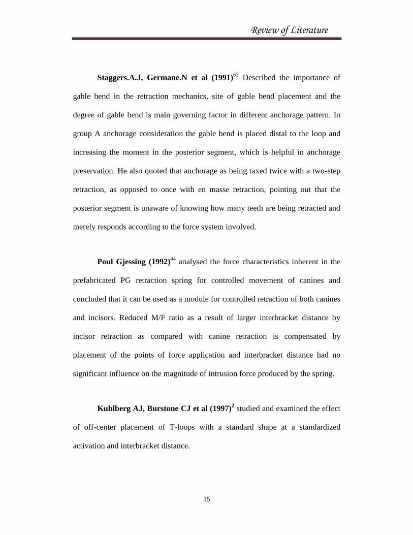
Staggers.A.J, Germane.N et al (1991)63
Described the importance of
gable bend in the retraction mechanics, site of gable bend placement and the
degree of gable bend is main governing factor in different anchorage pattern. In
group A anchorage consideration the gable bend is placed distal to the loop and
increasing the moment in the posterior segment, which is helpful in anchorage
preservation. He also quoted that anchorage as being taxed twice with a two-step
retraction, as opposed to once with en masse retraction, pointing out that the
posterior segment is unaware of knowing how many teeth are being retracted and
merely responds according to the force system involved.
Poul Gjessing (1992)44
analysed the force characteristics inherent in the
prefabricated PG retraction spring for controlled movement of canines and
concluded that it can be used as a module for controlled retraction of both canines
and incisors. Reduced M/F ratio as a result of larger interbracket distance by
incisor retraction as compared with canine retraction is compensated by
placement of the points of force application and interbracket distance had no
significant influence on the magnitude of intrusion force produced by the spring.
Kuhlberg AJ, Burstone CJ et al (1997)2 studied and examined the effect
of off-center placement of T-loops with a standard shape at a standardized
activation and interbracket distance.

Review of Literature
16
A centered T-loop produces equal and opposite moments with negligible
vertical forces.
Off-center positioning of a T-loop produces differential moments. More
posterior positioning produces an increased beta moment while more
anterior positioning produces an increased alpha moment.
A standard shaped T-loop can be used for differential anchorage
requirements by altering the activation and mesial-distal position of the
spring.
Ravindra Nanda (1997)46
described the biomechanical basis for
extraction space closure in group A, B & C anchorage situation using both
segmental T-loop ( 0.017x0.025 TMA) and continuous T-loop archwire
(0.017x0.025 TMA and 0.016x0.022 SS). Increasing posterior. For group A ,B &
C anchorage the loop is positioned distally, in center and anterior to the extraction
space respectively. But in group A anchorage high pull headgear is used
commonly to control posterior tooth position.
Raymond E. Siatkowski, (1997)48
systematic approach to closing loop
design for use in continuous arch wires is presented in Part-1. The design process
uses Castigliano's theorem to derive equations for moment-to-force ratio (M/F) in
terms of loop geometry. The equations are used to optimize designs by optimizing
Review of Literature
17
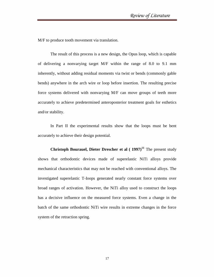
M/F to produce tooth movement via translation.
The result of this process is a new design, the Opus loop, which is capable
of delivering a nonvarying target M/F within the range of 8.0 to 9.1 mm
inherently, without adding residual moments via twist or bends (commonly gable
bends) anywhere in the arch wire or loop before insertion. The resulting precise
force systems delivered with nonvarying M/F can move groups of teeth more
accurately to achieve predetermined anteroposterior treatment goals for esthetics
and/or stability.
In Part II the experimental results show that the loops must be bent
accurately to achieve their design potential.
Christoph Bourauel, Dieter Drescher et al ( 1997)11
The present study
shows that orthodontic devices made of superelastic NiTi alloys provide
mechanical characteristics that may not be reached with conventional alloys. The
investigated superelastic T-Ioops generated nearly constant force systems over
broad ranges of activation. However, the NiTi alloy used to construct the loops
has a decisive influence on the measured force systems. Even a change in the
batch of the same orthodontic NiTi wire results in extreme changes in the force
system of the retraction spring.
Review of Literature
18
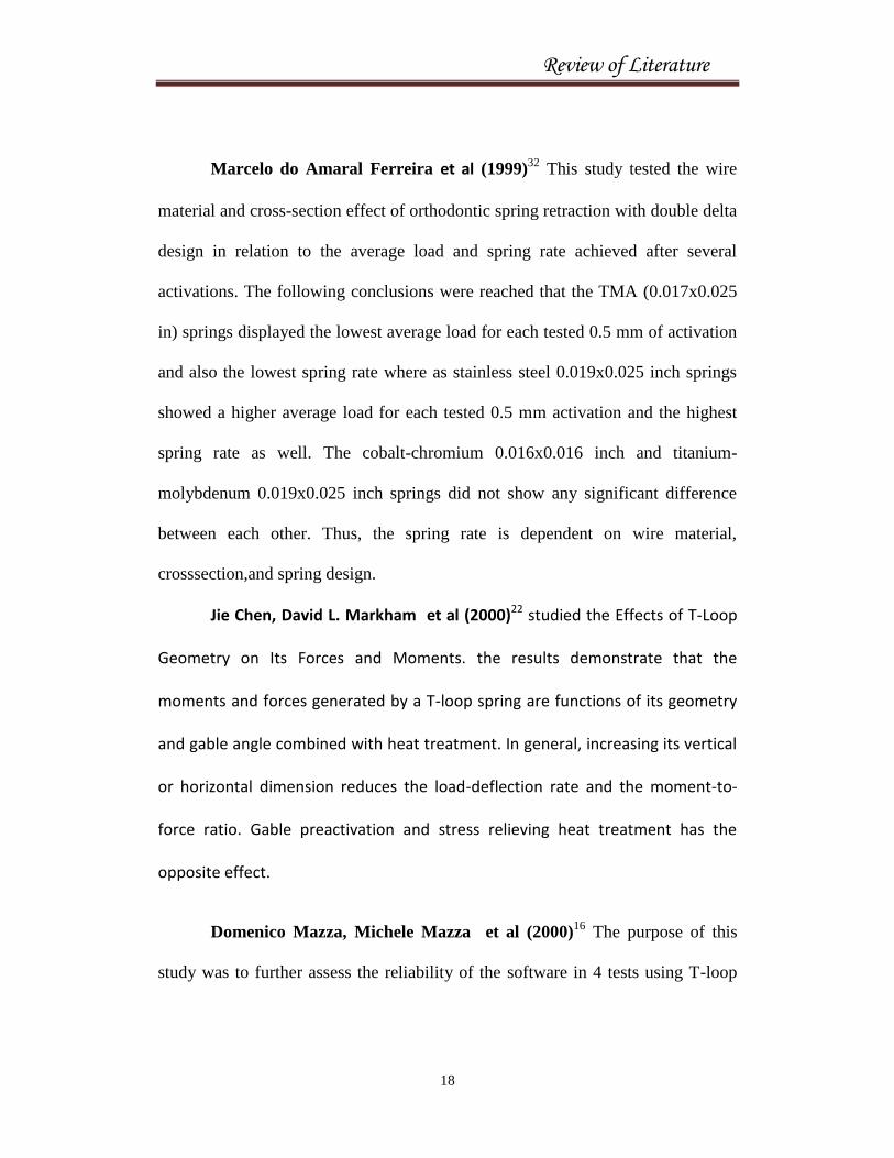
Marcelo do Amaral Ferreira et al (1999)32
This study tested the wire
material and cross-section effect of orthodontic spring retraction with double delta
design in relation to the average load and spring rate achieved after several
activations. The following conclusions were reached that the TMA (0.017x0.025
in) springs displayed the lowest average load for each tested 0.5 mm of activation
and also the lowest spring rate where as stainless steel 0.019x0.025 inch springs
showed a higher average load for each tested 0.5 mm activation and the highest
spring rate as well. The cobalt-chromium 0.016x0.016 inch and titanium-
molybdenum 0.019x0.025 inch springs did not show any significant difference
between each other. Thus, the spring rate is dependent on wire material,
crosssection,and spring design.
Jie Chen, David L. Markham et al (2000)22 studied the Effects of T-Loop
Geometry on Its Forces and Moments. the results demonstrate that the
moments and forces generated by a T-loop spring are functions of its geometry
and gable angle combined with heat treatment. In general, increasing its vertical
or horizontal dimension reduces the load-deflection rate and the moment-to-
force ratio. Gable preactivation and stress relieving heat treatment has the
opposite effect.
Domenico Mazza, Michele Mazza et al (2000)16
The purpose of this
study was to further assess the reliability of the software in 4 tests using T-loop
Review of Literature
19
springs. A numerical simulation of a determined experimental condition relative
to a T-loop spring was carried out in each test. Numerical and experimental
results were compared, and the precision of the analytical tool was assessed
relative to a variety of parameters of the spring. Since the comparison between
numerical and experimental results showed good agreement along the entire range
of activation of the spring, the reliability of the software is sufficient for the
clinical purposes of the segmented arch technique.
Faulkner, Bill Lipsett et al (2001)17
This numerical study evaluated
several appliances (rectangular loops and L-loops) used to vertically align teeth.
Consideration was given to how these designs might be modified to produce the
appropriate force system to allow both movements to occur simultaneously. It was
found that the rectangular loop was the most appropriate choice for first-order
corrections. For the rectangular loops studied, the in-plane force system was
shown to be essentially independent of the out-of-plane effects, which allowed the
two corrections to be controlled separately.
One disadvantage of these force systems is that the intrusive/extrusive
forces are nearly linearly related to the amount of vertical activation, which
suggests that the force level will decrease as vertical movement occurs.
Stanley Braun et al (2002)64
Gable bends are frequently incorporated into
a variety of loop configurations to provide appropriate moment-to-force (M/F)

Review of Literature
20
ratios in the controlled closure of space between individual teeth or groups of
teeth.Appropriate magnitudes and occlusogingival locations of the Gable bends
are shown to be vital to maintain the neutral position of the closing loop.
Concluded that Gable bends should be distributed occlusogingivally in all loop
configurations to achieve forecastable M/F ratios at the active and reactive teeth.
Guilherme Thiesen et al (2005 )18
this study was done to determine the
mechanical characteristics of beta titanium T-loops with and without 0 and 180
degree gable bends and constructed from 0.017x0.025 inch and 0.019x0.025 inch
wire. The results showed that the transverse section of wire had the greatest effect
on the horizontal force produced by the loops. Significantly lower levels of
horizontal force where obtained with smaller 0.017x0.025 inch wire. Loops with
gable bend yielded high moment force ratios, where as loops without gable bends
had lower moment force ratios and T-loops with helices yielded lower magnitudes
of horizontal force and moment force ratios than plain T-loop.
Mohammad Reza Safavi et al (2006)37
compared the M/F ratios of four
different closing loops: 3D analysis using the finite element method
(FEM)Adding preactivation bends to the VHC, T- and L-loops increased the M/F
ratios to acceptable levels at 1 mm activation, but there was a dramatic increase in
the M/F ratio as the loops deactivated to 0.1 mm. The results indicate that loop
activation should be maintained to avoid applying high M/F ratios.

Review of Literature
21
Thomas R. Katona, Jie Chen et al (2006 )67
It has been demonstrated
that first-order (anti-rotation) bends have the intended effect of increasing the
My/Fx ratio without changing the Mz/Fx ratio. Similarly, second-order (anti-
tipping) bends have the desired increasing effect on the Mz/Fx ratio without
affecting the My/Fx ratio. Thus, it is concluded that first- and second-order gable
bends in 0.016 x 0.022-in stainless steel triangular (8 x 8 x 8 mm) loops have
uncoupled effects on the clinically critical M/F.
Rodrigo F. Viecilli et al ( 2006)54
An optimal beta-titanium alloy 0.017 x
0.025-in T-loop spring was designed by using a simulation performed with LOOP
software (dHAL Orthodontic Software, Athens, Greece) to allow compensation
for anterior unit-position effect on the final force system. The force systems
produced by this T-loop spring with and without geometric correction of the
brackets have significant differences that should be considered in the segmented
arch approach to space closure and concluded the effects of steps, angles, and
vertical forces were combined to produce an ideal T-loop design that would
provide a more determinate force system. The effects and force systems are
estimates based on simplified locations of the centers of resistance, assuming
relatively constant behavior of the centers of rotation.
Proffit (2007)43
mentioned that the performance of closing loop is
determined by the amount of force it delivers, moment it generates and its relative

Review of Literature
22
position to the bracket. The location of the loop is an important factor in
determining space closure and the gable bend incorporated. The gable bends in
the closing loop functions as a V bend in the archwire is sensitive to its position.
Only if it is in the center of the span does a V bend produce equal forces and
couples on the adjacent teeth.
Renato Parsekian Martins,Peter H. Buschang et al ( 2008)50
Using the
Loop software program they systematically modified a .017x.025-in TTLS (10.6
mm) that was preactivated with a 45° gable bend distal to the loop, and simulated
the effects. As the gable bend was moved posteriorly, the moment increased at the
posterior bracket more than it decreased at the anterior bracket. As the loop was
brought closer to the anterior bracket, the posterior moment decreased at the same
rate that it increased anteriorly. As the loop was increased in size, the moments
increased both posteriorly and anteriorly. As the interbracket distance increased,
the posterior moment decreased, and the anterior moment remained constant and
concluded that the size of the loop should be slightly increased, to 10.7 mm, and it
should be placed 2 mm from the anterior bracket, with a preactivation bend of
45°, 4 to 5 mm from the posterior bracket (after 4 mm of activation).
Y. Mahesh Kumar,N.S. Ravindran et al ( 2008)72
The magnitude and
direction of the initial displacement of the canine were studied by means of
double-exposure interferometry using four different canine retraction springs, that
Review of Literature
23
is, closed coil spring, open coil spring,PG spring, and T-loop retraction spring and
concluded that the T-loop may be preferred whenever minimal tipping is
performed. The PG spring may be preferred over other springs whenever a higher
magnitude of displacement is desired. Closed coil springs may be preferred
whenever a reasonable magnitude of displacement is required and reasonable
tipping is allowed.
Michael Swain; Peter Herbison et al (2008)73
the temperature effects on
the forces, moments and moment to force ratio of nickel-titanium and TMA
symmetrical T-loops were studied and concluded that temperature significantly
influenced the forces and moments produced by NiTi closing loops, with values
increasing as the temperature increased. The M:F ratios of NiTi loops were less
affected, with no significant changes with temperature for the 15º and 30º
preactivation loops, although some change was noted for the non-preactivated
loops. TMA wires showed significance for some force measurements, but were
generally not influenced by temperature.
Renato Parsekian Martins; Peter H. Buschang et al ( 2008)49
in this
study the force acting on curvature and preactivated bends in titanium T-loop
springs were compared for 7 mm of activation and forces and moments were
registered after each 0.5 mm of deactivation and concluded that although both
loops show symmetrical moments in their anterior and posterior extremities and

Review of Literature
24
can be used for group B anchorage, the curvature preactivated TTLS delivers
lower horizontal forces and higher MF ratios than the acute preactivated V-bend
TTLS.
Renato Parsekian Martins, Peter H. Buschang et al (2009)51
The
purpose of this study was to evaluate the distal tipping of partially retracted
canines and the mesial movement of the molars. In eleven patients T-loop springs
with 45° gable bends distal to the loops preactivated for group A (maximum
anchorage) and metallic bone markers served as references. The canines were
retracted until enough space was available for alignment of the incisors without
proclination. Oblique (45°) radiographs were taken immediately before the initial
activation and after partial retraction and concluded that the T-loop spring used in
this investigation produced controlled tipping of the maxillary canines, but it did
not produce controlled tipping of the mandibular canines or translation of the
molar as expected.
Michael Swain, Peter Herbison et al ( 2009)13
This in-vitro study
investigated the loads (forces), moments, and moment-to-force ratios (M:F)
generated during the activation and deactivation of T closing loops made of
rectangular nickel-titanium (NiTi) and titanium-molybdenum alloy (TMA) wires
incorporating either 0°, 15° or 30° of preactivation and concluded that;
Review of Literature
25
1. TMA generally produced a higher mean force over its activation range
compared with the equivalent NiTi closing-loop specimens.
2. The nonpreactivated closing loops failed to produce an optimum M:F for
theoretical tooth movement via translation.
3. All preactivated TMA and NiTi closing-loop specimens produced an M:F
≥10:1 at some point in their deactivation range, irrespective of the force
delivered.
4. In the assumed optimal biologic force range for tooth movement
investigated (50-150 g), the NiTi preactivated closing loops produced an
M:F of ≥10:1 over a greater deactivation range than did their TMA
counterparts.
5. With increasing degrees of preactivation, the M:F also increased over the
deactivation range for all closing-loop specimens of both materials.
Jie Chen, Serkis C. Isikbay et al (2010)24
compared three T-loop closing
archwires of 0.016x0.022-inch stainless steel with interloop distance of 38mm,
42mm and 46mm to quantify the 3D force system with a continuous closing loop
archwire will allow the clinician to make an informed decision when selecting the
archwires. The 42-mm T-loop closing archwire (TL42) positioned the T-loop in
the middle of the interbracket distance of the lateral incisor and canine brackets.
The 38-mm (TL38) and the 46-mm (TL46) archwires positioned the T-loop 2 mm

Review of Literature
26
anterior and 2 mm posterior to the middle of the interbracket distance,
respectively. Concluded that the intrusion/extrusion force, would also occur
depending on the loop locations. Placing the loop mesially (TL38) would extrude
the incisor and intrude the canine, while placing the loop in the middle (TL42) or
distally (TL46) showed an opposite effect. Thus, when a T-loop is placed
eccentrically in the space to be closed, the moment will be higher on the tooth
closer to the loop.
Renato Parsekian Martins et al ( 2011)49
in this study the effect of
preactivation on the force system of symmetrical beta-titanium T-loop springs
were compared and concluded that :
1. The concentrated bend preactivation produced higher horizontal forces
and lower LD ratios than did the curvature preactivation.
2. Preactivation by concentrated bends produced more overlap of the vertical
extensions of the TLSs than did preactivation by curvature.
3. Both preactivations produced similar moments during deactivation.
4. Preactivation by curvature produced higher MF ratios than did
preactivation by concentrated bends.

Review of Literature
27
Sergei Godeiro Fernandes Rabelo Caldas,a Renato Parsekian Martins
et al (AJO 2011) this study was done to evaluate the load decay on the force
system of TLSs preactivated by concentrated bends over time. The TLSs had
dimensions of 6 mm in height by 10 mm in length 0.017 x 0.025 inch TMA wire
and were preactivated with concentrated bends. The result showed that the TLSs
preactivated by concentrated bends suffered progressive deformation over time.
This effect was critical on the first 24 hours on the moment reduction, the
decrease in the rate of moment reduction, and the decrease in the overlap of the
vertical extension of approximately 1 mm, causing a horizontal force reduction at
a given activation.
Luiz Gonzaga Gandini et al ( 2011)31
The purpose of this study was to
use photoelastic analysis to compare the system of forces generated by retraction
T-loop springs made with stainless steel and titanium-molybdenum alloy with
photoelastic analysis and concluded that The force system released by the springs
showed an M/F ratio that was similar in both sides independent of the type of the
alloy used to construct the springs. Considering the force magnitude, the T-loop
made of TMA showed a lower force magnitude when compared with the T-loop
spring made of SS.

Review of Literature
28
FINITE ELEMENT METHOD
Melvin L. Moss et al (1985)35
The application of the concepts of
continuous mechanics and of the numerical techniques of the finite element
method permits the development of a new and potentially clinically useful
method of describing craniofacial skeletal growth. This new method differs
from those associated with customary roentgenographic cephalometry in that
its descriptions and analyses are invariant; that is, they are independent of
any method of registration and super-imposition. Such invariance avoids the
principal geometric constraint explicit in all analytical methods associated with
conventional roentgenographic cephalometry. They proved that the FEM permits
analysis of the skull at a scale significantly finer than previously possible , by
considering cranial structure as consisting of a relatively large number of
contiguous finite elements.
Kazuo Tanne, Charles J. Burstone et al (1987)28
The three-dimensional
finite element model of the lower first premolar was constructed on the basis of
average anatomic morphology and consisted of 240 isoparametric elements.
Principal stresses were determined at the root, alveolar bone, and periodontal
ligament (PDL). Concluded that the pattern and magnitude of stresses in the
periodontium from a given magnitude of force were markedly different, depending
Review of Literature
29
on the center of rotation of the tooth.
Haskell (1990)20
modeled loops as 2-D beam elements, and one end of the
loop was completely restrained. The finite element analysis was carried out in two
steps: the first one was to apply the required forces and moments till the other end
spring became horizontal, the second step involved the known activations in the
horizontal direction. The M/F ratios of these springs could then be deduced from the
analysis.
Kazuo Tanne et al (1991)26
in this study a three dimensional finite element
analysis , investigated the pattern of initial tooth displacement associated with
varying root lengths and alveolar bone height affect the patterns of initial tooth
displacement. The center of resistance and center of rotation shifted towards
alveolar crest in the short root lengths and more of alveolar bone loss. They
concluded that the forces applied during orthodontic treatment should take
into consideration, factors such as to produce optimal and desired tooth movement.
Wilson et al (1991)68
studied the action of removable appliance to retract
maxillary canine into a first premolar extraction space and concluded that the
obliquely directed tipping forces applied to a finite element model of a maxillary
canine tooth resulted in a lower maximal prinicipal stress at the cervical margin
compared to a mesio-distal directed force. This may be due to increased bone
bending in the buccopalatal dimension as opposed to the mesio-distal dimension.
Review of Literature
30
Tanne et al (1993)29
investigated stress distributions in the maxillary
complex from head gear forces by means of three dimensional finite element
analysis. The stress distributions in the maxillary complex from headgear forces
by means of three dimensional finite element analysis. The stress distributions in
the sutures varied according to their anatomic locations relative to force
directions. The maxillary complex exhibits postero-inferior displacement with
clockwise rotation from the horizontal headgear.
Melsen et al (1999)12
used a two dimensional finite element model to
describe the force systems developed by cantilever different configurations during
incisor intrusion. The cantilevers with a curvature pi combined retraction and
intrusion forces. All other configurations resulted in combined protrusion and
intrusion, which reversed into retraction and according to the variations in
deactivations.
Schneider J.et al (2002)56
determined the optimal force system for bodily
movement of a single-root tooth, with an orthodontic bracket attached using the
numerical finite element method. It determined that optimal F/M ratio for
translation depends strongly on tooth geometry and the knowledge of root
geometry is important in defining an optimal force system.

Review of Literature
31
Chang Yi et al (2004)6 compared the effects of a multiloop edgewise archwire on
distal enmass movement with a continuous arch wire. The stress distribution and
displacement of the maxillary dentition were analyzed when class one
intermaxillary elastics (300 g/side) and 5 degree tip-back bends were applied to
the ideal archwire. The MEAW seems to have advantages for distal enmass
movement of the maxillary dentition.
P.M. Cattaneo, M. Dalstra, and B. Melsen et al (2005)5 this study was
sought to determine the impact of the modeling process on the outcome from FE
analyses and to relate these findings to the current theories on orthodontic tooth
movement.in a series of FE analysis stimulating teeth subjected to orthodontic
loading, the influence of geometry/morphology, material properties and boundry
conditions were evaluated. The accurate description of alveolar bone morphology
and the assignment of nonlinear mechanical properties for the PDF elements
demonstrate that loading of the periodontium cannot be explained in simple
terms of compression and tensionalong the loading direction. Tension in the
alveolar bone was far more predominant than compression.
Review of Literature
32
Maria Elisa Rodrigues Coimbra et al (2008)33
The purpose of this
study was to evaluate the use of computer simulation to predict the force and the
torsion obtained after the activation of teardrop loops of 3 heights (6, 7, and 8
mm). The loops were subjected to tensile load through displacements of 0.5, 1.0,
1.5, and 2.0 mm, and the resulting forces and torques were recorded. The loops
were designed in AutoCAD software, and finite element analysis was performed
with Ansys software this computer simulation accurately predicted the
experimentally determined mechanical behavior of teardrop loops of different
heights and should be considered an alternative for designing orthodontic
appliances before treatment.
Yue Huang, Ludger Keilig et al (2009)75
compared torque angle/torque
moment characteristics in three types of brackets self-ligating Hanson Speed,
Damon MX and conventionally ligated Discovery using finite element analysis
with 0.018x0.025 in and 0.019x0.025 in archwires. Of three different alloys
stainless steel, titanium molybdenum, and nickel titanium for torque of 20 deg and
concluded that the adaptation of torque movements to the biomechanical reactions
of the periodontium is best done by proper selection of both wire dimension and
wire alloy. The effect of the bracket system is of minor importance, with the
exception of brackets with an active clip (eg, Speed), which had the least play and
the lowest torquing moments of all the wires.

Review of Literature
33
Issa Fathima Jasmine et al (2011)21
studied the proper angle of
microimplant insertion in cortical anchorage. The microimplants were inserted at
30, 45, 60, and 90° to the bone surface. A simulated horizontal orthodontic force
of 200 g was applied to the center of the microimplant head, and stress
distribution and its magnitude were analyzed with a 3-dimensional finite element
analysis program. Analysis of the stress distribution in the cortical and cancellous
bones showed that the stress was absorbed mostly in the cortical bone, and little
was transmitted to the cancellous bone.
Hussein H. Amrnar, Peter Ngan et al (2011)1 in this study they have
demonstrated the potential of 3-dimensional modeling and finite element analysis
as clinical tools in treatment planning for orthodontic tooth movement. An
anatomically accurate 3-dimensional models reconstructed from cone-beam
computed tomography scans were used to simulate the retraction of a single-rooted
mandibular canine with a miniscrew placed as skeletal anchorage. Concluded that
CBCT reconstruction and FE simulation can provide reliable information on the
stress pattern around the miniscrew implant and the PDL of the loaded tooth there
by using fully 3D, patient-specific approach, multi-tooth orthodontic systems can
be modeled and proper multiple miniscrew placement points can be virtually tested
preoperatively to determine the optimal treatment plan. Interference with roots can
be predicted, and patient-specific cortical bone thicknesses are preserved. This

Review of Literature
34
study demonstrates the potential of our method as an effective clinical tool for
optimizing miniscrew anchorage stability and minimizing patient risk.
Yukio Kojima et al (2012)76
The purpose of this article was to clarify the
relationship between force directions and movement patterns. They concluded
that when the power arm was lengthened, rotation of the entire dentition
decreased. The posterior teeth were effective in preventing rotation of the anterior
teeth. In cases of the high-position miniscrew, bodily tooth movement was almost
achieved and vertical component of the force produced intrusion or extrusion of
the entire dentition was observed.

Materials and Methods
35
MATERIALS AND METHODS
A 3-dimensional finite element model of a maxillary arch and intact
dentition with first premolar extracted, brackets and archwires are created
(Figure 1).
The materials used are three dimensional models of the following components;
1) The maxillary arch in dentition and first premolar extracted are
obtained from the computed tomography scan with a slice thickness of
0.5 mm.
2) The periodontal ligament
3) The alveolar bone
4) A standard conventional preadjusted edgewise brackets of 0.022 slot
Roth prescription are used.
5) Double keyhole loop archwires of 0.019x0.025 inch stainless steel with
mild reverse Curve of Spee.
6) T-loop archwires of 0.019x0.025 inch stainless steel with mild reverse
Curve of Spee.
MODELING:
The first step involved in construction of three dimensional finite
element model is modeling. The modeling will be done using a software called
Pro/Engineer. Pro/E is a 3D software which is a product of Parametric
Technology Corporation. Using the software models can be created and edited
Materials and Methods
36
with ease. These models represent geometry in terms of points, lines, area and
volume. The constructed complicated smooth object can be represented
geometrically as simple pieces called Elements.
Three Dimensional Modeling of Maxillary Dentition:
Computerized tomography (CT) image acquisitions in the DICOM
(digital imaging communications in medicine) format of an adult dry human
skull was obtained using 120 kV, 150 mA, 512 x 512 matrix, field of view
14 x 14 cm and slice thickness of 0.5 mm.
These CT images consisted of 165 sections along the axial axis and
123 sections along the coronal axis, was then imported into the software
program Pro Engineer Wildfire version 4.0 and a geometric model was
generated that could be manually adjusted to get the exact shape and curves in
different sketch planes. Then the geometric model is discreted into several
small elements, connected with nodes.
All elements and nodes were numbered so that a setup of matrix
connectivity was established. This greatly affects the computing time. The
elements could be one, two or three-dimensional and in various shapes and
should not overlap each other but are connected only at the key points termed
as nodes. The joining of elements at the nodes and eliminating duplicate nodes
was termed as ‘Meshing’ (Figure 2). Equations were developed for each
element in the FEM mesh and assembled into a set of global equations that
Materials and Methods
37
modeled the properties of the entire system. Once meshing was done then the
lateral curves were created to ensure lateral connectivity of the geometric
model. From the curves, surfaces were created using a command called
Boundaries (Figure 3). Boundaries means that suppose an element is
constructed on the computer and a force is applied to it, it will act like a free-
floating rigid body and will undergo a translatory or rotatory motion or a
combination of the two without experiencing deformation. To study its
deformation, some degrees of freedom must be restricted (movement of the
node in each direction x, y, and z) for some of the nodes. Such constraints
were termed boundary conditions.
From these surfaces a solid was generated. The condition to define a
solid will be that the envelope of surfaces should be closed and non
intersecting. Once the tooth was developed in similar fashion other parts such
as the periodontal ligament and alveolar bone were created and assembled.
Construction of arch wires:
- A 0.019x0.025 inch stainless steel archwire was chosen.
- In the archwire two double keyhole loops of dimension 7mm in height
were constructed one distal of lateral incisor and other distal of canine.,
bilaterally
- A symmetrical T-loop measuring 7mm in height and 10mm wide using
0.019 x 0.025 stainless steel was constructed bilaterally in the centre of
extraction space.

Materials and Methods
38
- Mild reverse Curve of Spee was incorporated for both the loops.
Archwires with the loops were prepared using measuring instruments
like Vernier calipers and screw gauge. These measurements were build into
models , feature by feature using PRO – E software. Wire bends were then
created by a command called sweep where the trajectory and cross section
were defined to create the model. A separate analysis was done on the curved
wire model to incorporate the reverse Curve of Spee and reaction were
calculated. These reactions are incorporated in the actual model for analysis.
All the modeled images were then assembled together in the assembly module.
Once the assemblage was completed it was then exported to an analysis
package. The export was through a bidirectionally understandable translator
called IGES (initial graphics exchange specification).
FINITE ELEMENT ANALYSIS:
This study was done using Ansys Workbench 11 a recent version of
Ansys which can import models with 100% data Transfer or with 0% data
loss. Once imported the software can do an automatic meshing with defined
material properties. The software establishes contacts automatically and
defines them as bonded contact. This is of great use as less time is required in
selecting surfaces to define contacts especially when there are lots of
components between which contact need to be defined.

Materials and Methods
39
The constructed modeled images of maxillary arch with dentition,
brackets and archwire was imported to work bench ANSYS software and
relevant material properties were assigned. The material properties required
are Poissons ratio and Young’s modulus of each component as given in below
table. Then the periodontal ligament is extracted as surface from the root of
the tooth and thickness is assigned.
Materials Young’s modulus (Mpa) Poisson’s ratio
Tooth 20,000 0.30
Periodontal ligament 0.059 0.49
Alveolar bone 2,000 0.30
Bracket 200,000 0.30
Archwire 200,000 0.30
Table 1: Material properties of various components used in the study.
All these components were individually modeled and then assembled
to create 3D finite element models of the maxilla and the mandible depicting
en-masse retraction of six anterior teeth with
ANSYS Workbench (version 11.0; ANSYS, Canonsburg, Pa). Once all
the images were imported the software can do an automatic meshing with
defined material properties. Then the models were converted to elements and
nodes. Therefore, the type of Element used in our study was mid noded
Tetrahedron and the total number of elements and nodes established were

Materials and Methods
40
1,15,3876 and 1,57,233 respectively. Once Meshing and contacts are defined
the next process is to define boundary conditions. Boundary condition means
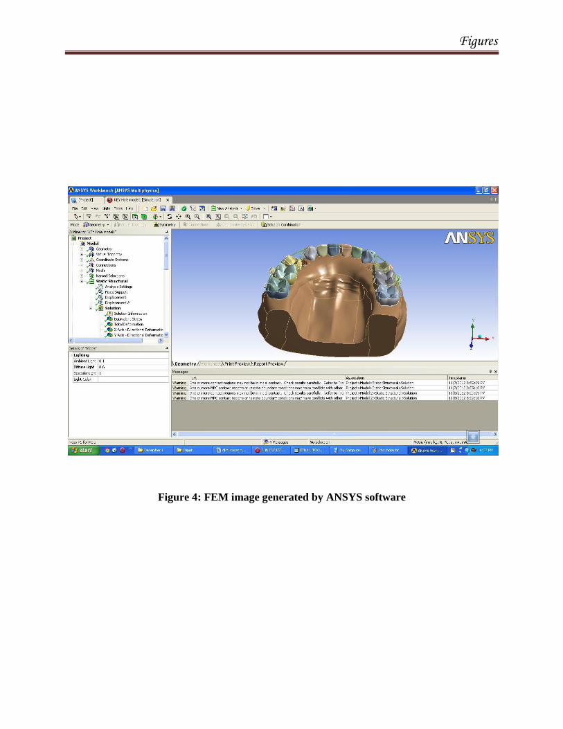
defining loads and restraints. Once the loads are defined then the problem is
solved and the results can be reviewed. (Figure 4).
A three dimensional finite element model of maxilla with Double
keyhole loop and continuous T-loop archwire was finally obtained (Figure 5).
The stress distribution and moment-force ratio was calculated for different
methods of activation :
Cinching – 1mm of activation was done by pulling and bending the archwire
distal to molar.
Ligature-tie - activation done with ligature by opening the loop for 1mm.
The assigned study groups were:
Group 1 :- Double Keyhole Loop
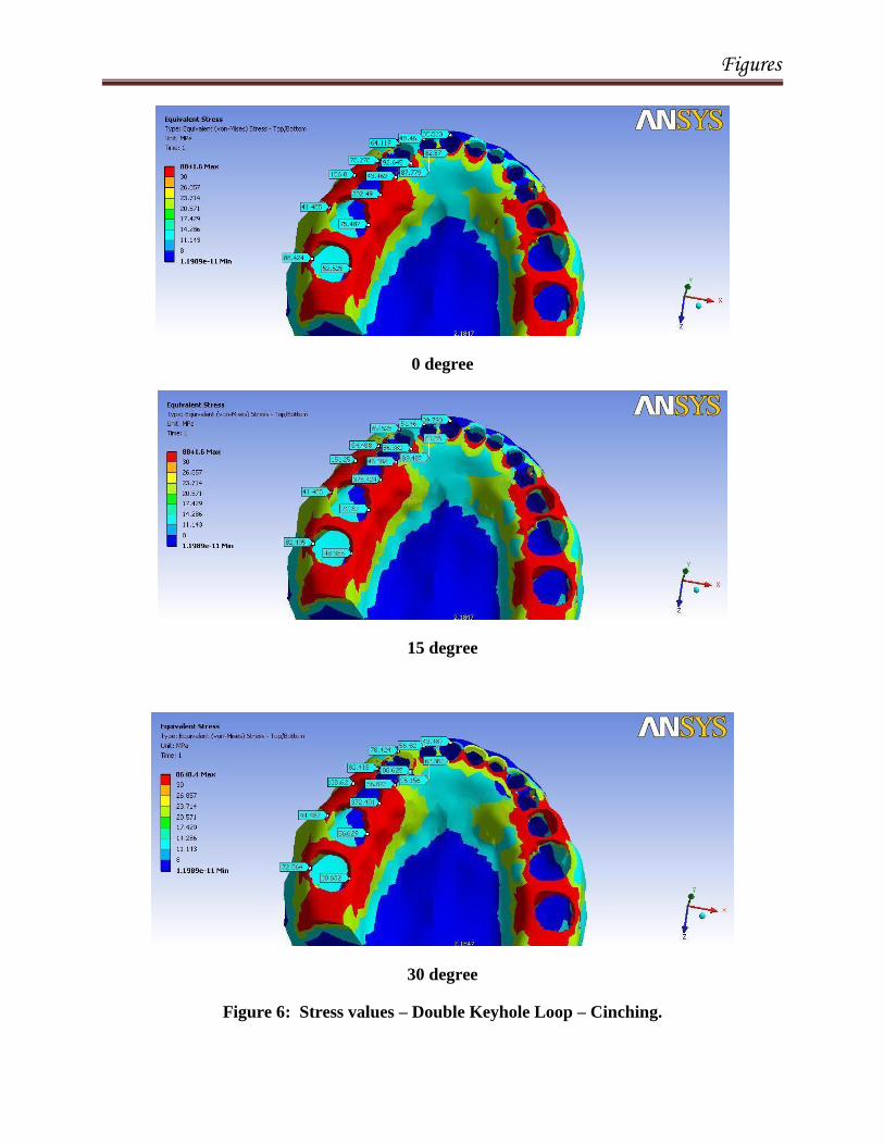
DKHL-C - activated by cinching with gable bend (0,15&30°) placed mesial
of Second Loop (Figure 6).
DKHL-L - activated with ligature-tie to the 2nd
loop and gable bend
(0,15&30°) placed mesial of second loop (Figure 7).
Group 2 :- Continuous T-loop
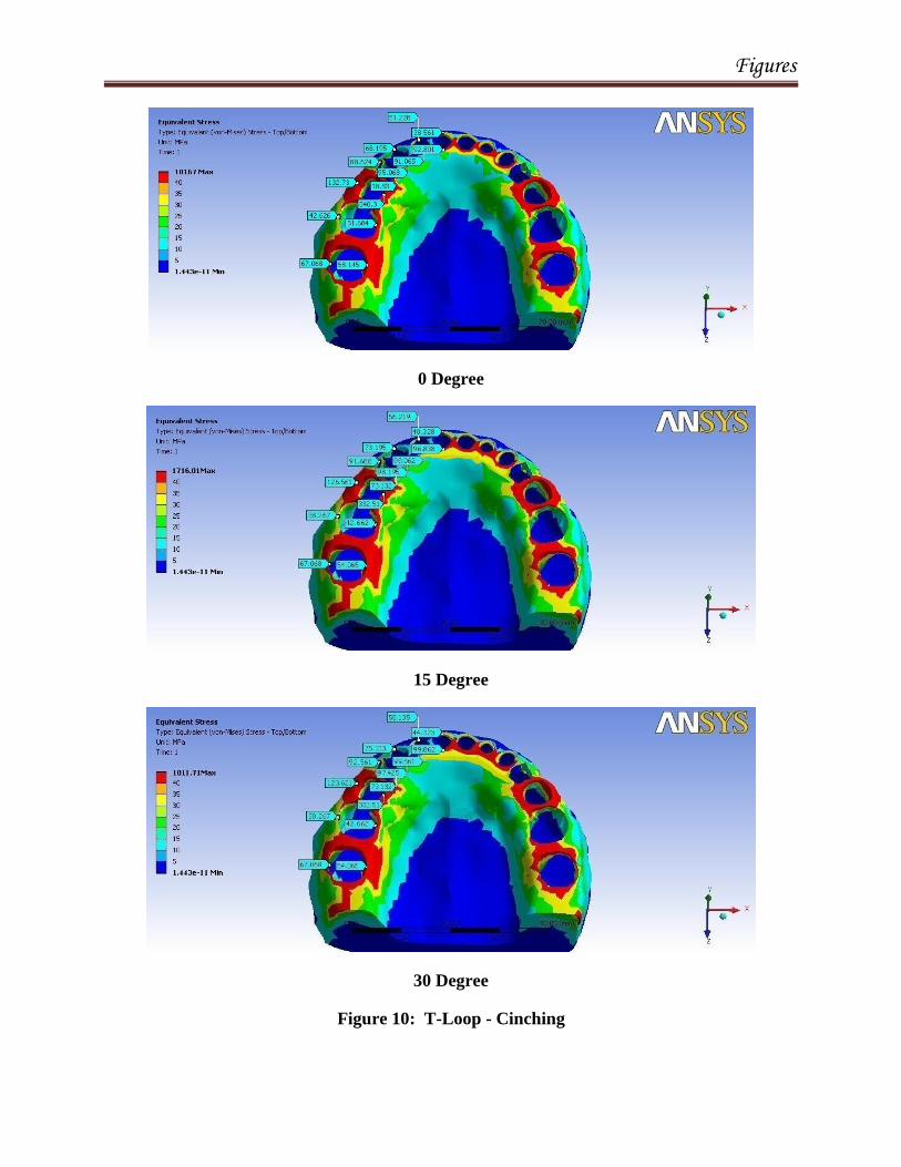
T-loop-C - activated by cinching with gable bend (0,15&30°) placed mesial

Materials and Methods
41
to the loop (Figure 10).
T-loop-L - activated using ligature tie to the loop and gable bend
(0,15&30°) placed mesial to the loop (Figure 11).
Group 3: DKHL-V1: Activated using ligature tie to the first loop and gable
bend (0,15&30°) placed mesial of the second loop. (Figure 8).
Group 4 :- DKHL-V2 :- activated with ligature-tie to the first loop and gable
bend (0,15&30°) placed mesial of the first loop (Figure 9).

Materials and Methods
42
Table 2 : Flowchart representation of designed Groups.

Materials and Methods
43
Statistics :
All statistical analysis was performed by using SPSS software package
(SPSS for windows XP, version 17.0). A Kruskal-Wallis Test was performed
to evaluate the stress distribution and overall displacement of the dentition for
en-masse space closure for group A anchorage in both the groups. A P-value
of ≤ 0.05 was considered statistically significant.

Figures
DKHL Cinching T-Loop Cinching
DKHL Ligature-Tie to 2nd loop T- Loop Ligature-Tie
DKHL Ligature-Tie to 1st loop
Figure 1: 3D model of Double key holeloop& T Loop

Figures
Mesh Image DKHL
Mesh Image of T-Loop
Figure 2: Pre-processing stage – MESH MODELS

Figures
Boundary images of DKHL
Boundary Image T-Loop
Figure 3: Boundary images
Figures
Figure 4: FEM image generated by ANSYS software

Figures
DKHL
T Loop
Figure 5: Analysis Image – Post Processing stage: Representation of the results in a colour
coded manner
Figures
0 degree
15 degree
30 degree
Figure 6: Stress values – Double Keyhole Loop – Cinching.

Figures
0 degree
15 Degree
30 degree
Figure 7: Stress Values: Double keyhole loop - Ligature - tie

Figures
0 Degree
15 Degree
30 Degree
Figure 8: Double keyhole- V1 – ligature tie to 1st Loop

Figures
15 Degree
30 Degree
Figure 9: Double key hole loop – V2 – Ligature –tie and Gable Bend to First Loop
0degrees
Figures
0 Degree
15 Degree
30 Degree
Figure 10: T-Loop - Cinching

Figures
0 Degree
15 Degree
30 Degree
Figure 11: T-Loop –Ligature tie
Results
RESULTS
The study was conducted to compare the biomechanical efficiency of
Double keyhole loop and continuous T-loop for en-masse space closure. The
resultant stress, displacement of the dentition and moment-force ratio was
calculated for 0,15 and 30 degree gable bend activated 1 mm using Cinching
and Ligature-tie while space closure in maximum anchorage cases using Finite
Element Analysis.
Stress distribution:
The values of stress distribution were shown in the spectrum of colours
ranging from red (very high) to blue (lowest) in the obtained analysis image.
The finite element analysis showed no statistically significant difference in
overall stress distribution for all the groups (Table 3 & Graph 1,2).
Maximum stress concentration was seen in the second premolar region
in all the groups when compared to anterior teeth.
Tooth Displacement:
The tooth displacement in all the groups were tabulated. The overall
displacement of dentition was not statistically significant in all the
groups.(Table 4 & Graph 3,4).
44
Results
Center of resistance in ‘Y’ direction:
The center of resistance was calculated in all the groups for enmass
retraction of six anterior teeth in ‘Y’ direction. The results showed an apical
shift of the center of resistance with increase in gable bend from 0 degree to
30 degree for all the groups (Table 5 & 6).
Maximum center of resistance was observed in Group III at 30 degree
gable bend (9.18mm).
Center of resistance in ‘X’ direction:
The center of resistance in ‘X’ direction remained relatively constant
in all the groups even with increasing the degree of gable bend
( approximately 15 mm posterior to the bracket of the central incisor)
(Table 5 & 6).
Comparison of Moment-force ratio:
There was a progressive increase in moment-force ratio with increase
in gable bend with both the groups. (Table 5 & 6).
Maximum moment-force ratio of 11.2Nmm was observed in Group IV when
the gable bend was shifted mesially to th ligature-tito fthe firstloope first loop
and Ligature-tie was placed to the first loop (Graph 3 & 4).
45

Results
Table 3: Comparison of stress distribution in all the groups
NS: Not significant;*p < 0.05 (significant);**p < 0.001 (highly
significant)
Sub
group
Group Mean SD sig
0 deg
DC .1534 .1057
.945
DS .1637 .1144
V1 .1736 .1204
V2 .1802 .1251
TC .1603 .1113
TS .1678 .1169
15
deg
DC .1485 .1007
.886
DS .1612 .1108
V1 .1678 .1135
V2 .1738 .1186
TC .1548 .1067
TS .1617 .1102
30
deg
DC .1520 .1030
.890
DS .1544 .1071
V1 .1654 .1161
V2 .1699 .1192
TC .1595 .1065
TS .1656 .1110

Results
Table 4: Comparison of displacements of teeth in all the groups
NS: Not significant;*p < 0.05 (significant);**p < 0.001 (highly
significant)
Sub
group
Group Mean SD sig
0 deg
DC 189.9809 154.6930
.223
DS 147.2331 123.9884
V1 151.8523 126.0723
V2 151.6494 124.2276
TC 185.2750 129.2550
TS 150.9597 104.5518
15 deg
DC 185.7537 151.3631
.426
DS 149.7646 121.9405
V1 153.8344 122.4700
V2 148.7084 104.4232
TC 184.2557 125.0230
TS 150.9180 99.6328
30 deg
DC 184.0869 146.3060
.505
DS 151.8319 119.0067
V1 155.9759 117.7378
V2 151.4666 97.4291
TC 185.4821 123.3930
TS 151.7730 98.0138

Results
Table 5:- Comparison of Moment-Force Ratio in T-loop
0 DEGREE 15 DEGREE 30 DEGREE
DKHL DKHL-C DKHL-L DKHL
-V1
DKHL
-V2
DKHL
-C
DKHL
-l
DKHL-
V1
DKHL-
V2
DKHL-
C
DKHL
-L
DKHL-
V1
DKHL-
V2
CR - Y 8.6 8.5 8.4 8.7 8.9 8.8 8.6 8.7 9.1 8.9 8.8 8.7
CR- X 15.6 15.5 15.4 15.4 15.4 15.0 15.1 15.2 15.4 15.2 15.4 15.5
MOMENT 169.7 150.8 185.3 188.3 170.4 181.3 167.9 195.5
163.8
176.3 182.5 208.3
FORCE 20.4 21.9 21.7 21.9 16.1 17.3 17.8 18.0 17.1 17.2 18.3 18.6
M:F
RATIO
8.3:1
8.5:1
8.5:1
8.6:1
9.3:1
9.5:1
9.4:1
10.8:1
9.9:1
10.2:1
9.9:1
11.2:1

Results
Table 6:- Comparison of moment – force ratio in T-loop
0 DEG 15 DEG 30 DEG
T-LOOP T-LOOP-C T-LOOP-L T-LOOP-C T-LOOP-L T-LOOP-C T-LOOP-L
CR - Y 8.8147 8.629 8.92465 8.817 9.189 9.019
CR- X 15.6827 15.598 15.267 15.126 15.407 15.319
MOMENT 185.5
159.4
180.5
197.5
167.317
195.4
FORCE 20.8067 21.9285 16.8782 17.5832 17.6974 18.5294
M:F RATIO 8.9:1 9.0:1 9.4:1 9.5:1 10.2:1 10.5:1

Results
Graph 1:- Comparison of stress distribution between Group I & Group II
Graph 2: Comparison of stress distribution between Group I (DKHL-L)
Group III & Group IV
0
20
40
60
80
100
120
140
160
180
200
0 DEGREE 15 DEGREE 30 DEGREE
DKHL-C
DKHL-L
T-LOOP-C
T-LOOP-L
142
144
146
148
150
152
154
156
0 DEGREE 15 DEGREE 30 DEGREE
DKHL-L
DKHL-V1
DKHL-V2

Results
Graph 3: Comparison of tooth displacement between Group I & Group II
Graph 4 : Comparison of tooth displacement between Group I (DKHL-L),
Group III & Group IV
0.14
0.145
0.15
0.155
0.16
0.165
0.17
0 DEGREE 15 DEGREE 30 DEGREE
DKHL-C
DKHL-L
T-LOOP-C
T-LOOP-L
0.14
0.145
0.15
0.155
0.16
0.165
0.17
0.175
0.18
0.185
0 DEGREE 15 DEGREE 30 DEGREE
DKHL-L
DKHL-V1
DKHL-V2

Results
Graph 5: Comparison of moment-force ratio between Group I & Group II
Graph 6:- Comparison of moment-force between Group I (DKHL-L), Group
III & Group IV
DKHL-C
DKHL-L
T-LOOP-C
T-LOOP-L
0
2
4
6
8
10
12
0
DGEREE
15
DEGREE
30
DEGREE
DKHL-C
DKHL-L
T-LOOP-C
T-LOOP-L
DKHL-L
DKHL-V1
DKHL-V2
0
2
4
6
8
10
12
0 DEGREE15
DEGREE 30
DEGREE
DKHL-L
DKHL-V1
DKHL-V2
Discussion
46
DISCUSSION
Over the years, there has been a constant debate on the different
methods of space closure depending on the relative merits of friction and
frictionless mechanics. However, much of this could not be resolved without
the knowledge of the optimal force levels involved. Storey and Smith
developed the concept of optimal force as the minimum force that results in
the maximum rate of tooth movement within the limits of biologic response65,
74. Quinn and Yoshikawa conducted a critical review on the different theories
that relate the orthodontic force to tooth movement and concluded that the rate
of tooth movement increases with increasing force up to a point, after which
increasing the force further no longer results in increase in tooth movement45
.
Nikolai defined optimum orthodontic force as that which produces the most
desirable biologic response and tooth movement with minimum tissue damage
and maximum patient comfort38
.
Space closure can be accomplished by friction and frictionless
mechanics. Friction mechanics causes binding and swing effect of the
archwire, thereby taxing the anchorage, increasing the force levels, resulting in
unwanted tooth movement25
. In this regard, loop/frictionless mechanics is
more beneficial in that a known force system is delivered to the teeth and
spaces are closed with the help of loops with forces and couples built into it.

Discussion
47
Therefore, while selecting the loop design for space closure, variables
such as loop design, thickness and properties of the wire used, type of tooth
movement desired and amount of force necessary must be taken into
consideration8.
Space closure using frictionless/loop mechanics can be done either as
segmental (two step retraction) where the canines are first distalized followed
by anterior retraction that is supposed to be less detrimental to anchorage.
However, the treatment time is prolonged. On the contrary, an en-mass /one
step retraction is more advantageous in terms of duration of treatment.
Two popular loops commonly employed in space closure are the
DKHL & T-loop. To best of our knowledge the literature is scant for Double
key hole loop and T-loop with regard to the force system delivered by these
loops during space closure. Thus in the present study we have evaluated the
efficacy of Double keyhole loop and continuous T-loop archwire mechanics
using finite element analysis.
The Finite Element Analysis (FEA) is a modern tool for numerical
stress analysis, which has the advantage of being applicable to solids of
irregular geometry that contain heterogeneous material properties. It provides
the orthodontist with quantitative data that can extend the understanding of
physiologic reactions that occur within the dento-alveolar complex. Finite
element method allows for exact modeling of the tooth, periodontal ligament
and mechanical properties of the tissue in three dimensions71
.

Discussion
48
Several studies have demonstrated that the FEM provides a solid,
workable foundation for modeling the system20, 21 42,71
. The greatest strength of
the FEM model is that it can be magnified infinitely both in terms of the actual
volumetric construction itself and the mathematical variability of its material
parameters. In biomechanics of tooth movement it is commonly used in
describing the reactions of dental and facial structures to orthodontic forces
and solving stress-strain problems in the mechanics14
.
When a continuous loop archwire is used the force system generated
becomes a statically indeterminate system thereby producing complex 3D
interactions24
. Finite element analysis facilitates the study of this 3D
interaction and the force system exhibited by it.
This is one of the first study, to compare the retraction efficiency of
Double key hole loop and T-loop evaluating the mechanical properties,
moment-force ratio and the stress distribution by two different methods of
activation (Cinching and Ligature-tie) at various degrees of gable bend (0, 15
& 30°).
Double keyhole loop is the most preferred retraction loop for space
closure with 0.22x0.028 inch slot Roth prescription as suggested by Roth55
. In
maximum anchorage cases a 0.019x0.025 inch stainless steel double key hole
loop is used3. This design of the loop provides a reasonably happy medium
between severe tipping and sliding mechanics of space closure with better

Discussion
49
control of canine rotation and the entire extraction space can be closed with
one set of archwire55
.
Symmetrical, T-loop was also used with the loop configuration
according to the specifications suggested by Burstone10
.
Gable bends are frequently incorporated into the loop configuration to
provide a moment to prevent the root apices of the teeth from moving in a
direction opposite to that of their crowns (uncontrolled tipping). In both the
loops gable bend was incorporated to prevent undesirable tooth movement
usually generated during activation of spring (distal tipping of canine) thus
providing a more controlled or bodily movement of the teeth and mild reverse
curve of spee was included for overbite control during space closure64
. The
moment-force ratio was calculated with respect to the center of resistance of
six anterior teeth as suggested by Gwang-Mo Jeong19
.
The present study evaluated the efficiency of en-masse space closure
using Double keyhole loop and T-loop under the following:-
Stress distribution.
Displacement of teeth.
Moment-force ratio.

Discussion
50
Comparison of conventional methods of activation in double keyhole loop and
T-loop (Group I and Group II)
Comparison of double keyhole loop activated through Ligature-tie to 2nd
loop
(Group I) and double keyhole loop- V1(Group III) activated through Ligature-
tie to first loop.
Comparison of Group III (DKHL-V1) and Group IV (DKHL-V2).
Comparison of Double keyhole loop (Group I) & T-loop (Group II):
The stress patterns during conventional methods of activation
(Cinching & Ligature-tie) was compared in both Group I(DKHL-C and
DKHL-L) and group II (T-loop-C and T-loop-L) for 1 mm of activation at
different degrees of gable bend showed no statistically significant difference in
stress distribution. This could be attributed to the morphology / design of the
loops, as the T-loop design has increased horizontal arm and two loops
incorporated in double key hole loop similarly increases the flexibility of
archwire producing an optimal force delivery leading to less stress distribution
in the anterior region.
However, the maximum amount of stress concentration was observed
in the second premolar region due to the proximity of gable bend in the
posterior region along with mild reverse Curve of Spee in the archwire..
Similarly, the overall displacement of the dentition was not
satatistically significant in all the groups.

Discussion
51
It is interesting to note that the moment-force ratio increased
progressively with increase in the degree of gable bend with both the loops.
Burstone stated that increasing the quantum of wire in the apical region as in
T-loop increases the moment-force ratio8,10
. However, DKHL was also found
to be equally efficient in delivering the desired moment-force ratio comparable
to the T-loop. This could be possibly due to the incorporation of two loops
along with the increase in gable bend.
The Ligature-tie activated T-loop (Group II – T-loop-L) showed higher
moment-force ratio with increasing the gable bend as compared to other
groups with maximum of 10.5Nmm at 30 degree gable bend. In this group
along with increase in moment-force ratio the centre of resistance also shifted
more apically(9.01mm) compared to other groups there by better torque
control of anterior teeth could be observed. This is in accordance with results
published by Yoshida et al in an invitro study who compared the height of
hook placement and force applied with respect to centre of resistance for en-
masse retraction and concluded that as the height of force application
increased more translatory tooth movement was observed34
.
In previous literature Jie Chen et al22
did an invitro study using
0.016x0.022 stainless steel segmented T-loop and compared the moment-force
ratio with respect to geometry and preactivation bends. The study showed that
increasing the horizontal and vertical dimension of the loop decreased the
moment-force ratio. The highest moment-force ratios were achieved at 1mm

Discussion
52
of activation ranging from 4-5Nmm without any gable bend / preactivation
bends.
Mohammad Reza Safavi37
compared the moment-force ratios of four
different closing loops with and without preactivation using FEM. The results
showed that stainless steel Opus and T-loop without preactivation bends had
constant moment-force ratios 7.6 & 7.2 mm respectively but both were below
the optimum moment-force ratio of 10:1.
However, in the present study we used 0.019x0.025 inch stainless steel
Continuous T-loop with loop configuration as suggested by Burstone10
. In the
present study moment-force ratio of 8 – 10 was achieved that is considered
desirable for bodily tooth moment. This could be possibly due to the
incorporation of gable bend along with mild reverse Curve of Spee.
Hoenigl et al30
examined the force and moment characteristics of a
prefabricated and preactivated centered T-loop. The result showed that the
moment-force ratio produced with the centered T-loop was 7.5 – 8 and
suggested that centered T-loop can be used to control clinically the force
system in the patients mouth.
Raymond E. Siatkwoski48
suggested that a constant moment-force ratio
of 8.0-9.1mm with out any residual moments could be achieved during en-
masse space closure with an uniform stress distribution in the periodontal
ligament using a continuous closing loop archwire which is in concurrence
Discussion
53
with our present study showing moment-force ratio of 8-10. Our study is the
first of its kind that shows that the Double Keyhole loop also has similar
efficiency as the T-loop.
Comparison of Group I (DKHL-L) and Group III (DKHL-V1) :
In Group III (DKHL-V1) wherein the Ligature-tie was shifted from
second loop to the first loop when compared to Group I (DKHL-L) showed no
statistically significant difference in stress distribution and overall
displacement of dentition among both the groups. The moment force ratio was
found to be similar in both the groups and consistently increased with
increasing the degree of gable bend as suggested in previous literature64
.
Maximum moment-force ratio was found in DKHL-L 10.2 Nmm at 30 degree
of gable bend.
Comparison of Group III (DKHL-V1) and Group IV (DKHL-V2):
The gable bend was shifted from mesial of second loop to the mesial of
first loop in Group IV compared to Group III with Ligature-tie tied to first
loop the stress distribution and displacement of teeth was not statistically
significant.
There was significant increase in the moment-force ratio when the
gable bend was shifted mesial to the first loop and tied with the Ligature-tie to
first loop. This could be due to the proximity of gable bend to the anterior
region along with the ligature tie to first loop the center of resistance shifted

Discussion
54
apically thereby increasing the moment-force ratio as high as 11.2Nmm at 30
degree gable bend producing lingual root movement of the anterior teeth.
Therefore, the Group IV (DKHL-V2) is beneficial in cases requiring
maximum anterior torque control after space closure.
Clinical Implications:
1. Maximum stress distribution was observed in the second premolar
region in all the groups. This could be due to the excessive force
produced on that region leading to undermining resorption thus
preventing orthodontic tooth movement and thereby increasing the
anchorage in the posterior segment.
2. Double key hole loop was found to be equally efficient as T-loop for
enmass retraction of anterior teeth, producing bodily tooth movement.
3. Morphology of two different loop was found to produce similar
biomechanical properties and similar increase in moment-force ratio
with progressive increase in gable bend.
4. The variation in Group IV (DKHL-V2) can be beneficially used for
maximum anchorage cases requiring anterior torque control with the
same archwire by shifting the gable bend mesial to first loop and
ligature-tie to first loop after space closure.

Discussion
55
Future :- This is an in-vitro (FEM) and cannot be directly extrapolated
to clinical situation because of the difference in biological response to
dentition and individual variation. Therefore clinical studies need to be done to
evaluate the biomechanical efficiency of Double keyhole loop and continuous
T-loop for maximum anchorage cases.

Summary
56
SUMMARY AND CONCLUSION
The present FEM study was carried out to compare the retraction
efficiency of two commonly used loops Double keyhole loop and Continuous
T-loop using finite element analysis.
The following conclusions can be drawn from the present study:
1. The resultant stress distribution and the overall displacement of the
dentition was not statistically significant among all the groups.
However, the maximum stress concentration was seen in the 2nd
premolar region due to the proximity of the gable bend and reverse
Curve of Spee. This is beneficial especially in maximum anchorage
cases, wherein the increased stress in the posterior region causes
undermining resorption, thereby prevents the mesial movement of the
posterior teeth.
2. The resultant moment-force ratio achieved a ratio of 8-10 in all the
groups. Nevertheless maximum moment-force ratio of 11.2Nmm was
observed in Group IV where the gable bend was shifted mesially to the
first loop and ligature tied to the first loop. This is more advantageous
in cases requiring maximum anterior torque control.
3. Therefore, both the loops were found to be equally efficient producing
desirable moment-force ratio for bodily tooth movement.
4. However, altering the gable bend and ligature tie produces greater
moment-force ratio for better anterior torque control.

Bibliography
57
BIBLIOGRAPHY
1. Ammar HH, Ngan P - Three-dimensional modeling and finite
element analysis in treatment planning for orthodontic tooth
movement. Am J Orthod Dentofacial Orthop. 2011 Jan;139(1):e59-71.
2. Andrew J. Kuhlberg and Charles J. Burstone - T-loop position and
anchorage control. Am J Orthod Dentofac Orthop 1997;112:12-8.
3. Antonino G. Secchi, Jorge Ayala – Contemporary treatment
mechanics using the straight wire appliance. Orthodontics current
principles and techniques. Grabber. Vanarsdall. Vig. 2012 Fifth
Edition.
4. Booth – Thesis – optimum forces from activation loops. University of
Texas, Houston.1971.
5. Cattaneo PM, Dalstra M, Melsen B. - The finite element method: a
tool to study orthodontic tooth movement. J Dent Res. 2005
May;84(5):428-33.
6. Chang Y I, Shin S J, Baek S H – Three dimensional analysis in the
distal enmasse movement of the maxillary dentition with multi loop
edgewise mechanics. European Journal of Orthodontics.2004:26(3)
339-345.

Bibliography
58
7. C.J.Burstone , J.J.Baldwin, D.T.Lawless - The application of
continuous forces to orthodontics. Angle orthodontics; 1961: 31 (1) :
1-14.
8. Charles J. Burstone, and Herbert A. Koenig - Optimizing anterior
and canine retraction. Am J Orthod Dentofacial 1976 July vol 70 :
1-19.
9. Charles J. Burstone and Ryszard J. Pryputniewicz – Holographic
determination of center of rotation produced by orthodontic force. Am
J Orthod Dentofacial Orthop 1980 April vol 77 : 29-38.
10. Charles J. Burstone – The segmented arch approach to space closure.
Am J Orthod Dentofacial Orthop 1982 November vol 82 : 361-378.
11. Christoph Bourauel, Dieter Drescher, Jan Ebling, David Broome
and Andreas Kanarachos - Superelastic nickel titanium alloy
retraction springs-an experimental investigation of force systems.
European Journal of Orthodontics 1997; 491-500.
12. Dalstra M, Melson B – Force systems develop by six different
cantilever configurations. Clin-Orth Res 1999; 2(1) 3-9.
13. Darnell Rose, Andrew Quick, Michael Swain, and Peter Herbison -
Moment-to-force characteristics of preactivated nickel-titanium and
titanium-molybdenum alloy symmetrical T-loops. Am J Orthod
Dentofacial Orthop 2009;135:757-63.

Bibliography
59
14. David J. Rudolph, Michael G. Willes - A Finite Element Model of
apical force distribution from orthodontic tooth movement. Angle
Orthod 2001;71:127–131
15. Demetrios J. Halazonetis – Understanding orthodontic loop
preactivation. Am J Orthod Dentofacial Orthop 1998 February 237 –
241.
16. Domenico Mazza, Michele Mazza, Mech Eng - Specialized Spring
Design in Segmented Edgewise Orthodontics: Further Verification of
Dedicated Software. Angle Orthod 2000;70:52–62.
17. Don Raboud, Gary Faulkner, Bill Lipsett, and Doug Haberstock -
Three-dimensional force systems from vertically activated orthodontic
loops. Am J Orthod Dentofacial Orthop 2001;119:21-9.
18. Guilherme Thiesen, Marcus Vinicius Neiva Nunes do Rego,
Luciane Macedo de Menezes and Roberto Hideo Shimizu - Force
systems yielded by different designs of T:loop. Aust Orthod J 2OO5
vol 2; l : 103-l 1O.
19. Gwang-Mo Jeong, Sang-Jin Sung, Kee-Joon Lee - Finite-element
investigation of the center of resistance of the maxillary dentition.
Korean J Orthod 2009;39(2):83-94.
20. Haskell B S, Spencer W A, Day M. – Auxiliary springs in continuous
arch treatment part I an analytical study using finite element method.
Am J Orthod Dentofacial Orthop 1990;98 – 387-397.

Bibliography
60
21. Issa Fathima Jasmine - Analysis of stress in bone and microimplants
during en-masse retraction of maxillary and mandibular anterior teeth
with different insertion angulations: A 3-dimensional finite element
analysis study. Am J Orthod Dentofacial Orthop 2012;141:71-80.
22. Jie Chen, David L. Markham, Thomas R. Katona - Effects of T-
Loop Geometry on Its Forces and Moments. Angle Orthod
2000;70:48–51.
23. Jie Chen, Irina Bulucea, Thomas R. Katona and Susan Ofner -
Complete orthodontic load systems on teeth in a continuous full
archwire: The role of triangular loop position. Am J Orthod
Dentofacial Orthop 2007;132: 143.e1-143.
24. Jie Chen, Serkis C. Isikbay, Edward J. Brizendine - Quantification
of three-dimensional orthodontic force systems of T-loop archwires.
Angle Orthod. 2010;80:754–758.
25. Joon-No Rhee, Youn-Sic Chun - A comparison between friction and
frictionless mechanics with a new typodont simulation system. Am J
Orthod Dentofacial Orthop 2001;119:292-9.
26. Kazuo Tanne, Takao Nagataki – Patterns of initial tooth
displacements associated with various root lengths and alveolar bone
heights. Am J Orthod Dentofac Orthop 1991;100:66-71.
27. Kazuo Tanne, Herbert A. Koenig and Charles J. Burstone -
Moment to force ratios and the center of rotation. Am J Orthod
Dentofac Orthop 1988;94:426-31.

Bibliography
61
28. Kazuo Tanne, Mamoru Sakuda, and Charles J. Burstone - Three-
dimensional finite element analysis for stress in the periodontal tissue
by orthodontic forces. AM J Orthod Dentofac Orthop 1987;92:499-
505.
29. Kazuo Tanne – Stress distribution in the maxillary complex from
headgear forces. Angle Orthodontist, 1993 Vol 63; 111-118.
30. Klaus D. Hoenigl, Josef Freudenthaler, Michael R. Marcotte, and
Hans-Peter Bantleon – The centered T-loop-a new way of
preactivation. Am J Orthod Dentofac Orthop 1995; 108:149-53.
31. Luiz Guilherme Martins Maia, Luiz Gonzaga Gandini -
Photoelastic analysis of forces generated by T-loop springs made with
stainless steel or titanium-molybdenum alloy. Am J Orthod
Dentofacial Orthop 2011;140:e123-e128.
32. Marcelo do Amaral Ferreira - The wire material and cross-section
effect on double delta closing loops regarding load and spring rate
magnitude: An in vitro stud. Am J Orthod Dentofacial Orthop
1999;115:275-82.
33. Maria Elisa Rodrigues Coimbra, Norman Duque Penedo -
Mechanical testing and finite element analysis of orthodontic teardrop
loop. Am J Orthod Dentofacial Orthop 2008;133:188.
34. Masaru Kobayashi; Noriaki Yoshida - Optimal Loading Conditions
for Controlled Movement of Anterior Teeth in Sliding Mechanics.A
3D Finite Element Study. Angle Orthod. 2009;79:1102–1107.

Bibliography
62
35. Melvin L. Moss, Richard Skalak - Finite element method modeling
of craniofacial growth. Am J Orthod Dentofacial Orthop 1985; June
vol 87 p.453-472.
36. M.G. Faulkner, A.W. Lipsett, K. EI-Rayes, D.L. Haberstock - On
the use of vertical loops in retraction systems. Am J Orthod
Dentofacial Orthop 1991 April vol.99 p. 328-336.
37. Mohammad Reza Safavi, Allahyar Geramy and Amir Kamyar
Khezri - M/F ratios of four different closing loops: 3D analysis using
the finite element method (FEM). Australian Orthodontic Journal
Volume 22 No. 2 November 2006.
38. Nikolai RJ. On optimum force orthodontic theory as applied to canine
retraction. Am J Orthod 1975;68:290-302.
39. Noriaki Yoshida, Paul-Georg Jost-Brinkman - Experimental
evaluation of initial tooth displacement, center of resistance, and center
of rotation under the influence of an orthodontic force. Am J Orthod
Dentofacial Orthop 2001;120:190-7.
40. N.Yoshida, Y.Koga – In vivo determination of the centres of
resistance of maxillary anterior teeth subjected to retraction forces. Eur
J Orthod. 2001 529-534.
41. Pedersen E, Isidor F, Gjessing P, Andersen K - Location of centres
of resistance for maxillary anterior teeth measured on human autopsy
material. Eur J Orthod. 1991 Dec;13(6):452-8.

Bibliography
63
42. Prasad Konda, Tarannum SA. - Basic principles of finite element
method and its applications in orthodontics. JPBMS, 2012, 16 (11).
43. Proffit W R. – Contemporary orthodontics ; 4th
edition 2007. (593-
595).
44. Poul Gjessing - Controlled retraction of maxillary incisors. Am. J.
Orthod. Dentofac. Orthop.1992 February.
45. Quinn RS, Yoshikawa DK. A reassessment of force magnitude in
orthodontics. Am J Orthod 1985;8:252-60.
46. Ravindra Nanda – Biomechanics in clinical orthodontics. 1997.
47. Raymond E. Siatkowski - Continuous arch wire closing. Part I loop
design, optimization and verification. Am J Orthod Dentofac Orthop
1997;112:393-402.
48. Raymond E. Siatkowski - Continuous arch wire closing loop design,
optimization, and verification. Part II. Am J Orthod Dentofac Orthop
1997;112:487-95.
49. Renato Parsekian Martins, Peter H. Buschang, Rodrigo Viecill,
Ary dos Santos-Pinto - Curvature Versus V-Bends in a Group B
Titanium T-Loop Spring. Angle Orthodontist, Vol 78, No 3, 2008.
50. Renato Parsekian Martins, Peter H. Buschang, Lidia Parsekian
Martins, and Luiz Gonzaga Gandini Jr - Optimizing the design of
preactivated titanium T-loop springs with Loop software. Am J Orthod
Dentofacial Orthop 2008;134:161-6.

Bibliography
64
51. Renato Parsekian Martins, Peter H. Buschang, and Luiz Gonzaga
Gandini Jr - Group A T-loop for differential moment mechanics: An
implant study. Am J Orthod Dentofacial Orthop 2009;135:182-9.
52. Richard J. Smith and Charles J. Burstone - Mechanics of tooth
movement. Am. J. Orthod. April 1984.
53. Robert P. Kusy, and J. F. Camilla Tulloch - Analysis of
moment~force ratios in the mechanics of tooth movement. AM J
Orthod Dentofacial Orthop 90: 127-131, 1986.
54. Rodrigo F. Viecilli - Self-corrective T-loop design for differential
space closure. Am J Orthod Dentofacial Orthop 2006;129:48-53.
55. Roth. H. Ronald, Graber and Swain- Treatment mechanics for
straight wire appliance. Orthodontic current principles and technique.
First indian edition 1991; 688-690.
56. Schneider – Numerical experiments on long time orthodontic tooth
movement. Am J Orthod Dentofacial Orthop 2002, 121 (3) 257-265.
57. Schwarz AM. Tissue changes incident to orthodontic tooth
movement.Int J Orthod. 1932;18:331–352.
58. SheauSoon Sia, Yoshiyuki Koga, Noriaki Yoshida - Determining the
Center of Resistance of Maxillary Anterior Teeth Subjected to
Retraction Forces in Sliding Mechanics.An In Vivo Study. Angle
Orthodontist, Vol 77, No 6, 2007.
59. Sergei Godeiro Fernandes Rabelo Caldas, Renato Parsekian
Martins - Force system evaluation of symmetrical beta-titanium T-

Bibliography
65
loop springs preactivated by curvature and concentrated bends. Am J
Orthod Dentofacial Orthop 2011;140:e53-e58.
60. Sergei Godeiro Fernandes Rabelo Caldas, Renato Parsekian
Martins - Effects of stress relaxation in beta-titanium orthodontic
loops. Am J Orthod Dentofacial Orthop 2011;140:e85-e92.
61. Spiro J. Chaconas, Angelo A. Caputo and Riley K. Hayashi -
Effects of wire size, loop configuration, and gabling on canine-
retraction springs. Am J Orthod Dentofacial Orthop 1974 January
p.A36 : 58-66.
62. Spiro J. Chaconas, Angelo A. Caputo, K. Miyashita. Force
distribution comparisons of various retraction archwires. Angle
Orthodontics 1989 No. 1, 25-30.
63. Staggers. A. j. Germane. N- Clinical consideration in the use of
retraction mechanics. Journal of clinical orthod. 1991;364-369.
64. Stanley Braun, and Jose´ L. Garcia - The Gable bend revisited. Am J
Orthod Dentofacial Orthop 2002;122:523-7.
65. Storey E, Smith R. Force in orthodontics and its relation to tooth
movement. Aust Dent J. 1952;56:11–18.
66. Su JH, Zhang DQ, Xu LY, Zhong PP.- 3-D finite element analysis
on center of resistance of upper anterior teeth. Shanghai Kou Qiang Yi
Xue. 2010 Oct;19(5):534-40.

Bibliography
66
67. Thomas R. Katona, Yen P. Le and Jie Chen - The effects of first-
and second-order gable bends on forces and moments generated by
triangular loops. Am J Orthod Dentofacial Orthop 2006;129:54-59.
68. Wilson – A finite element study of canine retraction with a palatal
spring; European Journal of Orthodontics 1991- 211-218.
69. Wook Heo, Dong-Seok Nahm, Seung-Hak Baek - En Masse
Retraction and Two-Step Retraction of Maxillary Anterior Teeth in
Adult Class I Women. A Comparison of Anchorage Loss. Angle
Orthodontist, Vol 77, No 6, 2007.
70. Vanden Bulcke MM, Dermaut LR, Sachdeva RC, Burstone CJ.-
The center of resistance of anterior teeth during intrusion using the
laser reflection technique and holographic interferometry. Am J Orthod
Dentofacial Orthop. 1986 Sep;90(3):211-20.
71. Vishal Seth Prasanth Kamath- A Marvel Of Modern Technology:
Finite Element Model. Virtual J Orthod – 2010 Dec.
72. Y. Mahesh Kumar, N.S. Ravindran and M.R. Balasubramaniam -
Holographic Analysis of the Initial Canine Displacement Produced by
Four Different Retraction Springs. Angle Orthod. 2008;00:368–372
73. Yeen Lim, Andrew Quick, Michael Swain, Peter Herbison -
Temperature Effects on the Forces, Moments and Moment to Force
Ratio of Nickel-Titanium and TMA Symmetrical T-loops. Angle
Orthodontist 2008 Vol 78, No 6.
Bibliography
67
74. Yijin Ren, Jaap C. Maltha - Optimum Force Magnitude for
Orthodontic Tooth Movement: A Systematic Literature Review. Angle
Orthod 2003;73:86–92.
75. Yue Huang, Ludger Keilig - Numeric modeling of torque capabilities
of self-ligating and conventional brackets. Am J Orthod Dentofacial
Orthop 2009;136:638-43.
76. Yukio Kojima, Jun Kawamura - Finite element analysis of the effect
of force directions on tooth movement in extraction space closure with
miniscrew sliding mechanics. Am J Orthod Dentofacial Orthop
2012;142:501-8.