accuracies achievable with indirect measurements of the direct solar irradiance component
TRANSCRIPT

Solar Energy, Vol. 23, pp. 509-512 Pergamon Press Ltd.. 1979. Printed in Great Britain
ACCURACIES ACHIEVABLE WITH INDIRECT MEASUREMENTS OF THE DIRECT SOLAR IRRADIANCE COMPONENTt
JEFFREY A. SECREST and INGE DIRMHIRN Department of Soil Science and Biometeorology, Utah State University, Logan, UT 84322, U.S.A.
(Received 13 July 1979; accepted 1 August 1979)
Abstract--Calculated direct solar irradiances from recording of global and diffuse irradiance are possible. However, to achieve the desired accuracy of 2 per cent of direct solar irradiance, corrections for the cosine error of the pyranometer to measure global irradiance and of the error induced by the shadowband in the diffuse irradiance have to be applied. Results then are satisfactory to zenith angles of approx. 80 ° .
INTRODUCTION
Of the solar irradiance reaching the earth's surface, only the direct component can be focused for conversion into highly concentrated energy. Separation of this com- ponent from the diffuse "sky" irradiance is necessary to provide the fundamentals for future site planning of high energy focusing solar conversion systems. Very few measurements exist, especially in mountainous terrain, over extended periods of time. Data received have to be of high accuracy ( +_ 2 per cent) to guide proper selections of the conversion system sites.
Two possible methods exist for measuring direct in- cident irradiance, denoted R~. The direct method utilizes a pyrheliometer mounted on a tracking device which measures R~. This approach requires daily monitoring to insure proper tracking. In the harsh mountain environ- ment of this project, high winds, frozen precipitation, and sub-freezing temperatures would necessitate more frequent maintenance. To avoid this frequent handling in a long term study, an indirect method of measuring Rt may be preferable, if it can be shown to maintain the desired degree of accuracy. The indirect method utilizes total global (solar and diffuse) and diffuse recordings from two pyranometers to calculate the direct incident irradiance R~.
Data for the global and diffuse irradiances were received from star type black and white pyranometers (Schenk). For the diffuse irradiance, a fixed shadowband was used that can be moved along two bars according to the declination of the sun.
There are two sources of measurement error when retrieving R~ by this approach. First, any cosine error depending on the zenith angle of the global pyranometer has to be corrected. This can be done based on labora- tory and field tests[l]. Second, a shadowband factor must be applied to the diffuse measurements because of depletion or enhancement by the band. The shadowband correction was established for the described setup by LeBaron et aL [2].
tThis study was performed with the support of the Department of Energy, under Grant No. EG-77-S-07-1656, Department of Energy, 1977.
APPROACH
Time intervals have to be defined so that the zenith angle of the sun, though changing through the period, is still representative and does not introduce any intoler- able error.
To establish the degree of accuracy in calculating the direct incident irradiance, RI, by the indirect pyranometer method, the following steps are taken:
1. Measure and record daily RI values with a pyr- heliometer mounted on a tracker.
2. Record daily global diffuse irradiance values with two pyranometers, the diffuse instrument being shaded with a shadowband.
3. Apply the appropriate correction values to the pyranometer measurements and calculate R~.
4. Compare the R~ measured in Step 1 to the R~ calculated in Step 3.
From geometric ceasiderations, the relationship be- tween Rr and the pyranometer measurements of total global (Rs + Ro) and diffuse (Ro) irradiances is:
Rt(pyran) = (Rs + RD) - RD COS 0 (I)
where the subscript on R~ denotes the use of pyranometers to calculate RI and O is the solar zenith angle. This angle is calculated using the equation:
cos 0 -- cos d~ cos 8 cos ~" + sin d~ sin 8 (2)
where 4' is the latitude of the observation point, 8 is the solar declination angle, and r is the hour angle.
To facilitate comparing the measured and calculated RI values, only data collected on clear days were evalu- ated. The procedure was as follows:
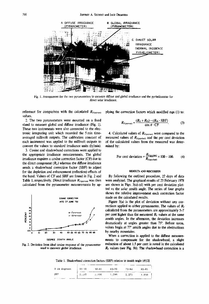
1. A pyrheliometer (Eppley NIP) was operated on a solar tracking device (Fig. 1). The NIP was electrically connected to a time integrator which averaged the mii- livolt output from the instrument over 5 rain intervals and stored the results on a magnetic cassette tape. The millivoit averages were later converted to standard irradiance units (ly/min) for comparison. This direct method of measuring RHpyrhet) was considered the
509
510 JEFFREY A. SECREST and INGE DIRMI-IIRN
A DIFFUSE 1RRADIANCE (PYRANOMETER)
B. GLOBAL IRRADIANCE (PYRANOMETER)
OLAR
3E INCIDENCE METER)
Fig. I. Arrangement for the two pyranometers to measure diffuse and global irradiance and the pyrheliometer for direct solar irradiance.
reference for comparison with the calculated Rl(pyran) values.
2. The two pyranometers were mounted on a fixed stand to measure global and diffuse irradiance (Fig. 1). These two instruments were also connected to the elec- tronic integrating unit which recorded the 5 rain time- averaged millivolt outputs. The calibration constant of each instrument was applied to the millivolt outputs to convert the values to standard irradiance units (ly/min).
3. Cosine and shadowband corrections were applied to the appropriate irradiance measurements. The global irradiance requires a cosine correction factor (CF) due to the direct component (Rs) whereas the diffuse irradiance needs a shadowband correction factor (SBF) to adjust for the depletion and enhancement (reflection) effects of the band. Values of CF and SBF are found in Fig. 2 and Table 1, respectively. Direct irradiance Rl(pyran) was then calculated from the pyranometer measurements by ap-
16: 14,
Z ~ 12: m I0:
4: 2:
I00'
COSINE CORREC110N 1472 (17 dUNE 78)
/ • - Forenoon /
~ / x -Afternoon
DEGREE ZENITH ANGLE
Fig. 2. Deviation from ideal cosine response of the pyranometer used to measure global irradiance.
plying the correction factors which modified eqn (1) to:
R/tpyran) = (Rs + RD) - (RD " SBF) cos 0" CF (3)
4. Calculated values of Rl(pyran) were compared to the measured values of R.pyrhol) and the per cent deviation of the calculated values from the measured was deter- mined by:
Per cent deviation = R.py,~.) x 1 0 0 - 100. gl(pyrhel)
(4)
RESULTS AND DISCUSSION
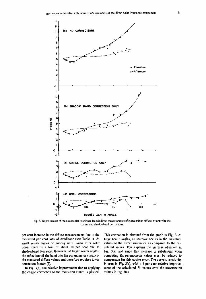
By following the outlined procedure, 22 days of data were analyzed. The graphical results of 23 February 1978 are shown in Figs. 3(a)-(d) with per cent deviation plot- ted vs the solar zenith angle. The series of four graphs shows the relative improvement each correction factor made on the calculated results.
Figure 3(a) is the plot of deviation without any cor- rections applied to either pyranometer. The values of RI calculated from the pyranometers are approximately 5-7 per cent higher than the measured RI values at the same zenith angles. In the afternoon, the deviation increases dramatically at angles greater than 75 °. Before noon, values begin at 77 ° zenith angles due to the obstructions by nearby mountains.
When a correction is applied to the diffuse measure- ments to compensate for the shadowband, a slight reduction of about 1.5 per cent is noted in the calculated Ri values (see Fig. 3b). The shadowband correction is a
Table 1. Sbadowband correction factors (SBF) relative to zenith angle (0)[2]
@ in degrees 40-50 50-60 60-70 70-80 80-85
~BF l.liO 1.100 1.090 1.075 1.050
Accuracies achievable with indirect measurements of the direct solar irradiance component 511
12 II I0 9 8
7 6 5 4
'5 2 I
0 -I I0 9 B
7 B
Z I L l u 5 i v '
a. 4
/ (a) NO CORRECTIONS ~ f
• - Forenoon x - A f t e r n o o n
I I I I I I
3 2 I
0 -I
(b) SHADOW BAND C O R R E C T I O ~
I I I I I I I
| i I i i i | i
~f (d] BOTH CORRECTIONS
, Io 7o . \ 80 -2 i. DEGREE ZENITH ANGLE
Fig. 3. Improvement of the direct solar irradiance from indirect measurements of global minus diffuse, by applying the cosine and shadowband corrections.
per cent increase in the diffuse measurements due to the measured per cent loss of irradiance (see Table I). At small zenith angles of midday until 3-4 hr after solar noon, there is a loss of about 10 per cent due to shadowband blockage. However, at larger zenith angles, the reflection off the band into the pyranometer enhances the measured diffuse values and therefore requires lower correction factors [2].
In Fig. 3(c), the relative improvement due to applying the cosine correction to the measured values is plotted.
This correction is obtained from the graph in Fig. 2. At large zenith angles, an increase occurs in the measured values of the direct irradiance as compared to the cal- culated values. This explains the increase observed in Fig. 3(a) and since this increase is substantial when computing R,, pyranometer values must be reduced to compensate for this cosine error. The curve's sensitivity is seen in Fig. 3(c), with a 4 per cent relative improve- ment of the calculated R, values over the uncorrected values in Fig. 3(a).
512 JEFFREY A. SECRESTand [NGE DIRMH1RN
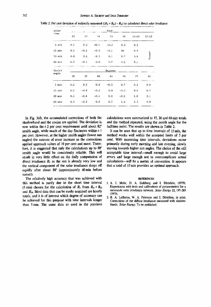
Table 2. Per cent deviation ofindirectlymeasured ((Rs +RD)-RD)to calculated direct solarirradiance
Solar Hour time
12 13 14 15 16 16:45 17:15
5min 0.1 0 . 2 +0.i -0.2 0.2 0.i
15min 0.i -0.i -0.5 -0.i 00 0.9
30min 0.0 0.2 -0.5 0.i 0.7 3.6
60min 0.2 -0.1 0.0 0.7 2.1 9.1
Zenith Desrees angle
50 55 60 65 70 75 80
5min 0,i 0.2 0.0 -0.3 0.7 0.2 0.0
15min 0.I -0.6 -0.2 0.0 -0.2 0.0 0.7
30min 0,1 -0.6 -0.4 0.0 -0.1 1.0 3.1
60min 0,1 -0.2 0,2 0.7 1.4 2.3 9.8
In Fig. 3(d), the accumulated corrections of both the shadowband and the cosine are applied. The deviation is now within the + 2 per cent requirement until about 820 zenith angle, while much of the day fluctuates within -+ 1
per cent. However, at the higher zenith angles (lower sun angles) the sources of error increase as the corrections applied approach values of 10 per cent and more. There- fore, it is suggested that only the calculations up to 80 °
zenith angle would be consistently reliable. This will result in very little effect on the daily computation of direct irradiance RI as the sun is already very low and the vertical component of the solar irradiance drops off rapidly after about 800 (approximately 40rain before sunset).
The relatively high accuracy that was achieved with this method is partly due to the short time interval (5 rain) chosen for the calculation of RI from Rs + RD and R~ Most data that can be easily acquired are hourly totals, and it is of interest which degree of accuracy can be achieved for this purpose with time intervals longer than 5 rain. The same data as used in the previous
calculations were summarized to 15, 30 and 60 rain totals and the method repeated, using the zenith angle for the halftime point. The results are shown in Table 2.
It can be seen that up to time intervals of 15 rain, the method works well within the accepted limits of 2 per cent. With increasing time intervals, deviations occur primarily during early morning and late evening, slowly moving towards higher sun angles. The choice of the still acceptable time interval--small enough to avoid large errors and large enough not to overcomplicate actual calculations--will be a matter of convention. It appears that a total of 15 rain provides an optimal approach.
REFERENCES
1. A. J. Mohr, D. A. Dahlberg and I. Dirmhirn, (1979). Experiences with tests and calibrations of pyranometers for a mesoscale solar irradiance network. Solar Energy 22, 197-203 t1979).
2. B. A. LeBaron, W. A. Peterson and I. Dirmhirn, in print. Corrections of the diffuse irradiance measured with shadow- bands. Solar Energy. To be published.