accelerating time-to-market in the global electronics industry
TRANSCRIPT

Accelerating Time-to-Market in the Global Electronics Industry
By
Elena Jean Folgo
Sc.B. Mechanical Engineering, Brown University (2000)
Submitted to the MIT Sloan School of Management and the Engineering Systems Divisionin Partial Fulfillment of the Requirements for the Degrees of
MASSACHUSETTS I
Master of Business Administration OF TEHNOL
and JUN 2 5 20Master of Science in Engineering Systems
LIBRARI!In conjunction with the Leaders for Manufacturing Program at the
Massachusetts Institute of Technology
June 2008
© 2008 Massachusetts Institute of Technology. All rights reserved.
Signature of Author
Certified by
Department of Engineering Systei6'& MIT Sload School of ManagementM4y 9, 2008
Deborah J(,Nightin kle, Thjis SupervisorProfessor of Practice, Aeronautics & Astro~a1tics and Engineering Systems
Certified by
Certified by
Accepted by_
Accepted by
EIte Rebentisch, Thesis SupervisorResearch Associate, Center for Technology, Policya2• Industrial Development
/ Donald Rosenfield, Thesis Reader (Management).- Rnir Lecturer, and Director, LFM Fellows Program
Richard Larson Professor ot Engineering Systems DivisionChair, Engineering Systems Division Education Committee
/ Debbie BerechmanExecutive Director of MBA Program, MIT Sloan School of Management
,Y
08
ES
#vk:S!
iWVL•
Certified by

This page has been intentionally left blank

Accelerating Time-to-Market in the Global Electronics Industry
ByElena Jean Folgo
Submitted to the MIT Sloan School of Management and theEngineering Systems Division on May 9, 2008 in Partial Fulfillment of the
Requirements for the Degrees of Master of Business Administration andMaster of Science in Engineering Systems
ABSTRACT
In today's electronics industry, fast time-to-market (TTM) and time-to-profit (TTP) is key tocustomer satisfaction and firm competitiveness. Optimizing the product development and newproduct introduction (NPI) process is particularly critical for products in dynamic marketsegments such as consumer electronics and telecommunications. This analysis will utilize a casestudy to define the current state of the development process for a top electronics manufacturingservices (EMS) player conducting original design manufacturing (ODM) projects in a dynamicmarket. The analysis will identify process and organizational improvements that will eliminateproduct development waste in support of accelerating TTM and TTP using an enterpriseperspective.
Thesis Supervisor: Deborah J. NightingaleTitle: Professor of Practice, Aeronautics & Astronautics and Engineering Systems
Thesis Supervisor: Eric RebentischTitle: Research Associate, Center for Technology, Policy, & Industrial Development
-3-

This page has been intentionally left blank

Acknowledgments
This thesis would not have been possible without the support of my sponsor company. Theenergy and commitment of the employees at this company continues to amaze me. Thank youfor making my seven months educational, productive, and fun.
I had the great fortune of working with Eric Rebentisch, Deborah Nightingale and WarrenSeering on this project. They all provided a tremendous amount of help and guidance throughoutthe internship and the writing of this thesis.
To my friends in the LFM class of 2008: Each and every one of you has touched my life over thepast two years. I could not have chosen a more outstanding group of people to learn and growwith at MIT.
To my parents, Rosanne and Anthony Micich: Thank you for your support and encouragementthroughout this challenging chapter of my life.
To my husband, hero, and protector, Eugene Louis Folgo III: Thank you so much forencouraging me to come to LFM and for your love, patience and guidance during my time atMIT. I couldn't have done this without you.
-5-

This page has been intentionally left blank
-6-

Biographical Note
Elena Folgo spent her childhood in Phoenix, Arizona. She received a Bachelor of Sciencedegree from Brown University in Mechanical Engineering with a focus in Energy Conversionand Fluid and Thermal Sciences in the year 2000.
Prior to MIT, Elena worked for six years at Honeywell Engines, Systems & Services in Phoenix,Arizona. There, she held positions as a systems integration engineer and an engineering projectmanager and worked with a variety of aerospace and defense products. Elena plans to participatein the Accelerated Leadership Program (ALP) at Intel® Corporation in Santa Clara, CA uponsuccessful completion of the Leaders for Manufacturing (LFM) program.
-7-

This page has been intentionally left blank

Table of Contents
Acknowledgments ........................................................................................................................................ 5
Biographical Note..................................................................................... ............................................. 7
Table of Contents ....................................................................................... ........................................... 9
Table of Figures ............................................................................................. ...................................... 11
Table of Tables ................................................................................................. ................................... 13
1. Introduction and Summary ................................................................................ ....................... 15
1.1. The Electronic M anufacturing Services (EM S) Industry .................... .................... 15
1.2. The Significance Tim e-to-M arket.............................................. 17
1.3. OEM -EM S Collaboration ............................................................. .......................... 17
1.4. Key Players ................................................................................................................... 18
1.5. Hon Hai Precision Industry Co. (Ltd.)................................................................ 18
1.6. The Client Company........................................................................ ............ 191.6.1. The Client Company Product Life Cycle Process (PLC) .................................. 201.6.2. The ODM Business Developm ent Process ...................................... ..... .. 21
1.7. Background and Scope .............................................................. ............................. 22
2. Literature Review ......................................................................................... .............................. 25
2.1. The Product Developm ent Process for Electronics Products .................................... 25
2.2. Speed in Product Development............................................................................ 26
2.3. W aste in Product Developm ent ........................................................................... 26
2.4. Architecting the Enterprise for Strategic Advantage .................................................... 26
3. M ethodology.......................................................................................... ...................................... 29
4. A Case Study ............................................................................................................................... 31
4.1. Enterprise Overview ........................................... .................................................... 31
4.2. Product Development Process Overview............................................................ 32
4.3. The Project ................................................. 334.3.1. Developm ent Cycle Tim es.................................................... 344.3.2. Scheduled and Unscheduled Activities......................................... 35
4.3.2.1. Design Change Activity............................. 35
4.3.2.2. Concept/Prototype Phase .................................................................... 36
4.3.2.3. Engineering Validation ..................................................... 36
4.3.2.4. Design Validation ................................................................................ 37
4.3.2.5. Production Validation and Volum e Production Ramp .............................. 37
4.3.3. Root Cause Analysis for Project Delays................................................ .... 37
-9-

4.3.3.1. Project Organization .......................................................... ........................ 38
4.3.3.2. Project Planning .............................................................. ......................... 40
4.3.3.3. Requirem ents M anagem ent ................................................................ 40
4.3.3.4. Custom er Support ................................................................................ 41
5. Enterprise Architecture Analysis .................................................. ............................................ 435.1.1. Strategy ...................................................................................................... 435.1.2. Process .................................................................................................................. 435.1.3. Product/Services ........................................... ................................................... 445.1.4. Organization.......................................................................................................... 455.1.5. Know ledge ................................................ ....................................................... 465.1.6. Inform ation ................................................ ...................................................... 475.1.7. Policy/External Factors .......................................................... 48
6. Product Development Waste in the Current State ............................................... 506.1. Scatter ........................................................................................................................... 50
6.2. H and-O ff ........................ .................................. ............................................ 51
6.3. W ishful Thinking ..................................................... ........................................ 52
7. Recom m endations ............................................................................................................................. 537.1. Process .......................................................................................................................... 53
7.2. Organization................... ........ .............................................................................. 54
7.3. Know ledge .................................................................................................................... 54
8. Conclusion ............................................................................................ ....................................... 55
Endnotes ................................................................................................................................................... 57
-10-

Table of Figures
Figure 1. Client Company Organizational Structure ....................................... ........... 20
Figure 2. ODM Business Unit Incubation Process ....................................... ............ 20
Figure 3. Quick-Build Spiral Product Development Cycle ................................................ 20
Figure 4. Enterprise Conceptual Diagram .......................................................................... 32
Figure 5. Business Unit Product Life Cycle Process ....................................... ........... 32
Figure 6. Engineering and Manufacturing Change Orders by Development Phase .................. 35
Figure 7. Case Study Root Cause Analysis .......................................... .................. 38
-11-

This page has been intentionally left blank
-12-
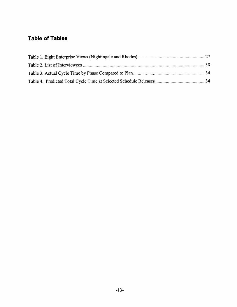
Table of Tables
Table 1. Eight Enterprise Views (Nightingale and Rhodes).......................................... ..... 27
T able 2. L ist of Interview ees ............................................. ..................................................... 30
Table 3. Actual Cycle Time by Phase Compared to Plan.................................... ......... 34
Table 4. Predicted Total Cycle Time at Selected Schedule Releases ..................................... 34
-13-

This page has been intentionally left blank
-14-
1. Introduction and Summary
1.1. The Electronic Manufacturing Services (EMS) Industry
The Electronics Manufacturing Services (EMS) industry is comprised of companies that
provide materials procurement, manufacturing, printed circuit board (PCB) assembly, product
testing, supply chain management, and aftermarket services for Original Equipment
Manufacturers (OEM) on a contract basis. The EMS business model emerged in the 1970s as
outsourcing "non-core" activities became a profitable practice for OEMs in the electronics
industry. This practice was made profitable by contract manufacturers that leveraged
economies of scale in manufacturing and procurement to deliver electronic manufacturing and
assembly services to OEMs at lower cost than the OEMs could achieve themselves. Over
time, contract manufacturing companies moved up the value chain, providing value-added
services such as testing, supply chain management, logistics and repair services to respond to
market needs. By the 1990s, OEMs came to rely on the services provided by EMS companies
to remain competitive as cost pressures intensified, manufacturing processes became more
complex, and product lifecycles got shorter. From the OEM perspective, outsourcing
manufacturing to EMS providers frees up capital, reduces labor costs, and improves
productivity for OEMs, and it enables OEMs to focus on their core competencies of R&D,
marketing and design.
EMS is characterized as a growth industry. According to Technology Forecasters, Inc, 2006
industry revenue grew 7.7% over 2005'. This is compared to historical growth rates of 20% to
25% in the 1980s and 1990s. During the 1990s, EMS companies often achieved scale and
global footprint by acquiring operations from their OEM customers, and acquisition accounted
for the growth observed in the industry. EMS companies continue to provide more services in
search of greater margins and higher growth. The largest area of growth in contract
manufacturing is in the area of Original Design Manufacturing (ODM), where a design is
created in-house and then sold to OEMs. Typically ODM work is centered on products that
are becoming commoditized, such as cellular phone handsets and desktop computers, for
which costs can be reduced by designing for manufacturability (DFM). ODM has been
-15-

identified as a high-growth area, partially due to its heavy use in high-growth industries such as
mobile phones and notebooks.
Revenue in this sector depends on the willingness of OEMs to outsource their supply chain
management, manufacturing, and design activities. The primary factors that affect EMS
market growth include OEM outsourcing trends and end-user market growth. Outsourcing is
expected to continue in the future as a business practice; however, many OEMs have
outsourced that majority of their value chain to EMS providers already. EMS companies
mainly serve the consumer electronics and telecommunications market and their growth is
largely tied to the growth of that sector. Industrial, automotive, aerospace and medical sectors
are today considered "niche" for EMS providers, but these areas could provide growth
opportunities as new outsourcing decisions get made.
Overall, costs in the industry are highly dependent on labor in low-cost regions and materials
costs. Labor comprises a large portion of the expenses for EMS providers, so they are
sensitive to cost increases in this area. Asia is the primary region for manufacturing and
assembly due to the advantages of low-cost labor and low material prices. Competition for
skilled employees in low-cost regions tends to drive wages up over time. Larger EMS
providers develop long-standing relationships with suppliers by bringing consistently high
sales volumes to them. However, even large EMS companies can struggle with high materials
costs when entering into a new region or a new market because the game is relationship-based.
Competition is fierce because the barriers to entry are so low. There are thousands of EMS
providers globally. OEMs can also easily bring these sections of the value chain back in-
house, if they so choose. There are relatively few customers in the computer and
telecommunications industry that can promise the volumes required to sustain the EMS
business model. Customers currently retain the power to negotiate heavily on price. Most
large EMS providers have a presence in Asia, Western Europe, and the Americas in order to
retain the flexibility to easily move manufacturing from one region to another. Because
margins are low, EMS providers are particularly sensitive to materials and labor cost increases,
and they are heavily affected by reductions in sales volumes. Successful EMS companies
-16-

quickly achieve scale and global footprint so they can produce in high volumes to satisfy
customer needs.
However, the landscape is changing. First, consolidation is anticipated in the future as the
industry matures. In October 2007, the number two industry player Flextronics International,
Ltd. acquired the number three player, Solectron. The next largest player now has only one-
third of the annual revenue of the new Flextronics, and as such the other players will have to
consolidate to compete with the scale and global footprint required to be competitive with
incumbents. Second, companies that focus on ODM as their primary business model have
successfully captured market share, specifically in the consumer electronics market.
Manufacturing expertise allows ODMs to offer OEMs customized solutions and also design-in
low cost features. Although the focus of EMS companies will remain in manufacturing
process excellence and supply chain management, offering design services is viewed as a
necessity to thrive in the future with ODMs in the market.
1.2. The Significance Time-to-Market
Time-to-market (TTM) and Time-to-Volume (TTV) are large factors in competitive advantage
for an EMS provider, especially in dynamic market segments such as consumer electronics and
telecommunications. TTM/TTV is particularly important for new products because getting to
market faster than the competition enables OEMs to capture market share. Introducing a new
product faster typically increases overall sales volume because obsolesce happens at the same
time as it would have if the product was introduced later. For many new products, OEMs may
enjoy premium pricing and cost advantages from the manufacturing learning curve. OEMs
that outsource manufacturing and design rely on EMS providers to drive toward accelerated
TTM, particularly in the area of new product introduction (NPI).
1.3. OEM-EMS Collaboration
As EMS manufacturers continue to offer complimentary services at all levels of the value
chain, collaboration between with EMS providers has become an important factor for OEMs as
they strive to reach cost and TTM goals. EMS providers have worked to understand the
-17-

strategic needs of their customers, and OEMs have developed manufacturing support
organizations to support EMS providers. Product complexity, demand variability, design
maturity and the related after-sales services provided, required cycles times and delivery
requirements are all factors that determine the level of collaboration required to meet joint
goals. Industry experts expect the Solectron acquisition to trigger consolidation in the
EMS/ODM industry, providing a greater incentive for OEMs to create strategic, longer-term
partnerships with key providers.
The lowest price mentality is prevalent in OEM companies and the build-to-spec/respond to
every request for proposal (RFQ) mentality is embedded in the EMS culture. Although OEMs
and EMS companies understand the benefits of collaboration, OEMs often push to squeeze the
margins of the EMS providers by competitive bidding or adding requirements after projects
have started and EMS providers respond by hiding information or by overstating their
capabilities when entering into contracts. This behavior prevents gains from collaboration,
resulting in sub-optimal performance for both parties.
1.4. Key Players
There are thousands of EMS providers worldwide. Taiwan-based Hon Hai Precision Industry
Co. (Ltd.), commonly known as Foxconn, is the EMS industry leader, although it is often
considered an ODM company. Singapore-based Flextronics International became the second
largest EMS provider after the acquisition of Solectron, Inc. Other notable players include
Florida-based Jabil Circuit and California-based Sanmina-SCI, Canada-based Celestica and
Luxemburg-based Elcoteq, each of which has less than 10% market share 2. The following
section focuses on the top industry player and the client company.
1.5. Hon Hai Precision Industry Co. (Ltd.)
In 2007, Hon Hai, commonly known as Foxconn, achieved a market capitalization of $43
billion and operates on a massive global scale3 . In China alone, the company employs 450,000
workers in almost a dozen provinces 3, accounting for 80% of its production capacity. Over
90% of the company's revenue comes from mobile phones, flat-panel TVs and computers with
-18-

customers such as Cisco, Nokia, Dell, Apple and Hewlett Packard. Foxconn has benefited
from strategic relationships with growing PC OEMs Apple and Hewlett Packard2. Between
2006 and 2007, Foxconn grew its revenue 45% and it is expected to grow its annual revenue by
30% over the next two years2.
Since 2002, Foxconn was consistently ranked top ten in the Business Week Info Tech 100, a
ranking of the top performers in the tech industry. It was ranked the 10th largest tech company
by Business Week in 2007 annual sales directly behind Microsoft4 . The company also
consistently ranks as one of the top patent earners in Taiwan and is one of the fastest
manufacturers in terms of Time-to-Market. Foxconn relentlessly focuses on cost reduction and
as a result often offers quotations 10% to 20% below major competitors. The focus on low-
cost is pervasive throughout the company culture. Another key aspect of the culture is that of
hard work with long hours and top-down decision making and management consistent with
Taiwanese-run contract manufacturing firms.
1.6. The Client Company
The Client Company* has a market capitalization of greater than $5B and also operates on a
global scale. The company participates in all the major EMS market segments, including
mobile, computing, consumer digital, and infrastructure, as well as niche segments such as
industrial, auto, and medical. The top 10 customers comprise no more than 60% of the
company's revenue base.
Like many EMS providers, the company grew largely by acquisition throughout the 1990s. In
2006, the company was reorganized from a region-based organizational structure to one
focused around market segments and product lines. Under the region-based structure,
resources were organized around the major regions of the world (i.e. Americas, Asia, and
Europe). The new organizational structure features a matrix where businesses are run as P&L
centers, with the support of centralized functions (e.g. finance, HR) that run across the business
units, as depicted in Error! Reference source not found..
The company name has been omitted for confidentiality purposes.
-19-

Figure 1. Client Company Organizational Structure
This shift has enabled the Client Company to gain synergies in SG&A expenses and to
effectively scale operations across market segments. It also provides customers with one
interface worldwide, instead of different representatives for each region. Challenges related to
process ownership, resource allocation across businesses, and effective vertical integration still
exist in the organization. The Client Company is aggressively pursuing an ODM portfolio, and
for this task it heavily relies on a centralized organization called the Centralized Technology
Function (CTF).
The Client Company culture can be characterized by customer focus, results orientation,
frugality, lack of bureaucracy, and entrepreneurial energy. The espoused values of the
company relate to collaboration, customer focus, execution, continuous improvement, and
business success.
1.6.1. The Client Company Product Life Cycle Process (PLC)
The Client Company Product Life Cycle (PLC) is the top-level business process that guides
the Client Company's business activities. It encompasses business development as well as
concept, development, production and end-of-life activities. The responsibility for this
-20-

process lies within the centralized Organizational Development organization, in the PLC
group. In general, the process is largely undocumented and in a constant state of flux. At the
time of this study, the process had been rolled out company-wide at a macro-level with
descriptions of the top-level steps, functional checkpoints, and phase gate requirements.
Some business units within the company had adopted the process and tailored it to their
individual needs. The tailored PLC process should be different for ODM work than the
process for EMS work because it includes conceptual development and engineering design
activities for product development.
1.6.2. The ODM Business Development Process
The primary responsibility for development of ODM platforms falls under the Centralized
Technology Function. The CTF's primary responsibility is to develop technology roadmaps
that meet current and future customer needs in conjunction with driving industrialization and
product and process development to support these roadmaps. As part of this responsibility,
development teams within the group focus on innovation and platform development based on
agreed-upon customer needs. Then, the company approaches customers with the developed
platform. Once a customer agrees to an ODM contract, the Client Company moves into the
product development cycle to refine the product based on customer-specific needs.
Meanwhile, the CTF works closely with platform developers and the PLC group to tailor the
corporate level PLC process to the needs of the fledgling business unit. As the customer-
base grows for a particular platform, the Client Company may develop that platform into a
product line, still under the umbrella of the CTF. If the business becomes sustainable and
large enough, it is spun off into its own P&L business entity within the Client Company.
This process is displayed pictorially in Error! Reference source not found..
-21-

Figure 2. ODM Business Unit Incubation Process
1.7. Background and Scope
As EMS providers begin to offer design services to OEMs, the ability to effectively collaborate
with OEMs becomes highly important. This is especially true for dynamic segments where
TTM is a key strategic objective. However, collaboration efforts for ODM projects (projects
for which the EMS provider is responsible for both design and manufacturing) often fall short
of what is necessary to successfully meet cost and schedule goals.
The entrepreneurial mindset associated with growth through acquisition tends to make process
implementation difficult within EMS organizations. Razor-thin margins coupled with
tremendous growth opportunities render investment in process development unattractive to
business managers. To complicate the problem, EMS providers must acquire talent from OEM
and ODM companies as they strive to provide flexible design services. Collaboration between
business, engineering, and manufacturing inside the EMS company for ODM projects requires
new skills, processes, and structures that are not yet fully understood by existing and new
employees and it is typically executed in a globally dispersed environment. As a result,
product development cycles tend to take longer and cost more than expected, even during short
lifecycle projects. EMS companies that are in the process of acquiring ODM talent are also in
a growth phase and are focused on allocating resources toward revenue generating projects
rather than for process development and improvement.
-22-

This study explores the current state EMS providers conducting ODM projects in dynamic
market segments and identifies improvement areas in support of the strategic goal of achieving
fast TTM through a demonstrative case study at the Client Company. In Chapter 2, a literature
review outlines concepts of lean product development and enterprise architecting that will be
used to analyze the current state of a business unit within the Client Company. Chapter 3
outlines the methodology by which research was conducted for this project. Chapter 4
describes a business unit within the Client Company, presents a case study to illustrate the
effectiveness of the current-state, outlines potential causes for project delays and presents a
root cause analysis for the specific case. Chapter 5 describes the enterprise using an enterprise
architecture framework. Chapter 6 draws on the case study and enterprise architecting analysis
to identify waste in the product development process. Recommendations are presented in
Chapter 7, and conclusions are presented in Chapter 8.
-23-

This page has been intentionally left blank
-24-

2. Literature Review
2.1. The Product Development Process for Electronics Products
Almost every company has a documented product development process. According to Ulrich
and Eppinger in Product Design and Development, the product development process for many
electronics products falls under the category of "quick-build" products and often follows a
spiral product development process 5. Under this process, the system-level design is first
decomposed into high-, medium-, and low-priority features. Then, the product is developed by
a series of design-build-integrate-test activities, beginning with high priority features for the
first prototype and continuing to develop prototypes until time or budget runs out. The generic
spiral development process flow is depicted in Error! Reference source not found.Error!
Reference source not found. below.
Many Iteration Cycles
Planning Concept System-Level Production
Mission Concept Cycle Plan CycleApproval Review Review Reviews
Figure 2. Quick-Build Spiral Product Development Cycle
This characterizes the product development process that is currently being followed in the
studied enterprise.
Many sources cite the fact that Toyota is able to develop new products faster, at lower cost,
and with higher quality than its competitors. Toyota has historically developed new products
in a fraction of the time it takes its competitors to develop similar products. The first time a
development team tries to use lean methods, a 30% to 50% time reduction is feasible and
further reductions become possible with experience6 . Toyota's lean product development
system has three mutually supportive subsystem elements: skilled people, tools & technology,
and process7 . The unique aspect of the lean product development system is that the focus is
shifted away from the documented process and toward the day-to-day activities by which a
finished product is developed.
-25-

2.2. Speed in Product Development
Development speed is commonly measured by the time between mission approval and the end
of production ramp. In Lean Product and Process Development, Dr. Allen Ward argues that
speed in product development should refer solely to the rate at which the organization learns
during development in order to gain competitive advantage through the development process6.
For the purposes of this analysis, product development cycle time will be evaluated using the
common metric.
2.3. Waste in Product Development
Product development waste is associated with inefficiencies in knowledge capture and barriers
to information flows. There are three primary categories of product development waste:
scatter, hand-off, and wishful thinking. Scatter is defined as "actions that make knowledge
ineffective by disrupting its flow," and "disrupts the subtle interactions required for
teamwork6." Handoff occurs when knowledge, responsibility, action and feedback are
separated 6. Handoff is a problem in organizations because it "results in decisions being made
by people who do not have enough knowledge to make them well or the opportunity to make
them happen6." Wishful thinking is defined as making "decisions without data or operating
blindly6 ." Included in this category is discarding knowledge gained through product
development cycles. The case study and the enterprise architecture analysis are used as tools
to identify product development waste in the studied enterprise.
2.4. Architecting the Enterprise for Strategic Advantage
The Toyota product development system is based on the assumption that there lies an intimate
connection between the organization and its environmentError! Bookmark not defined. The concept
of Enterprise Architecting can be used to characterize the elements of this connection.
Enterprise Architecting is defined as "applying holistic thinking to design, evaluate and select a
preferred structure for a future state enterprise to realize its value proposition and desired
behaviors." (Nightingale and Rhodes, 2007) The state of the enterprise contained in this case
-26-
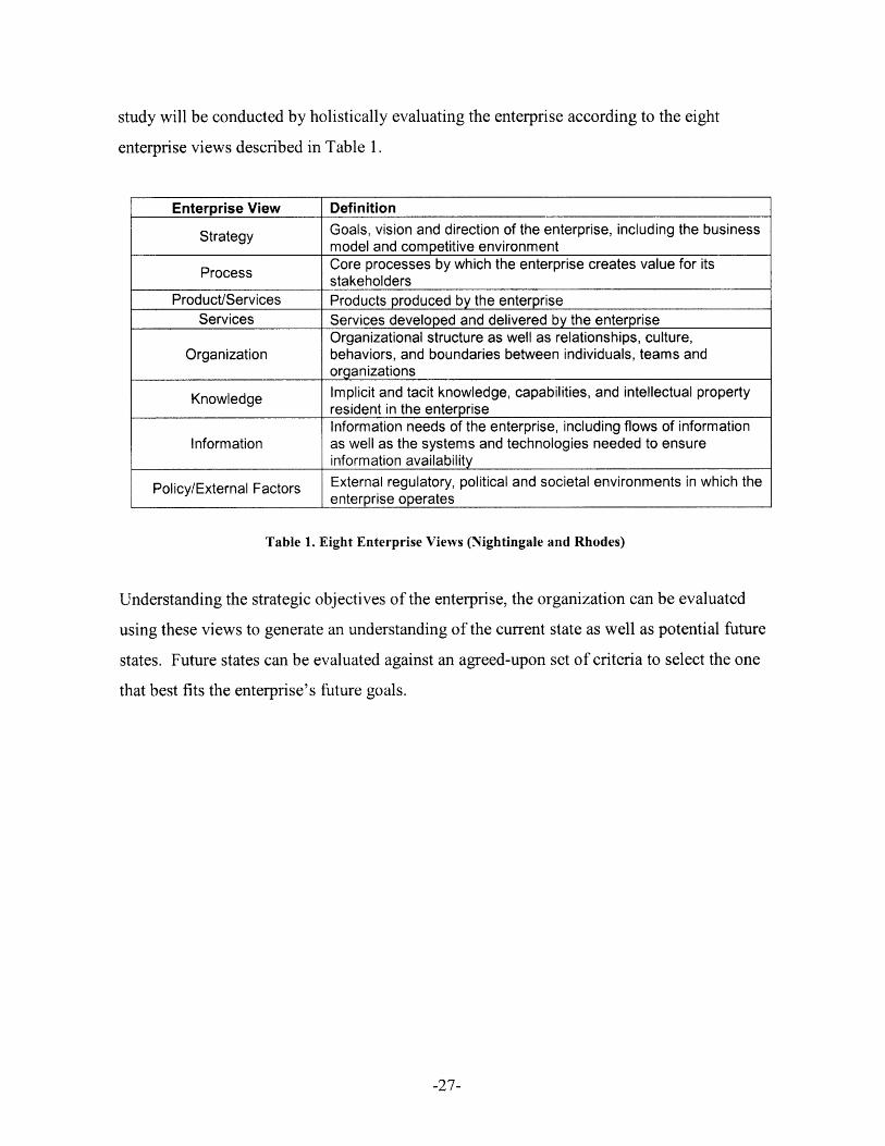
study will be conducted by holistically evaluating the enterprise according to the eight
enterprise views described in Table 1.
Enterprise View Definition
Strategy Goals, vision and direction of the enterprise, including the businessmodel and competitive environmentCore processes by which the enterprise creates value for its
Process stakeholdersProduct/Services Products produced by the enterprise
Services Services developed and delivered by the enterpriseOrganizational structure as well as relationships, culture,
Organization behaviors, and boundaries between individuals, teams andorganizations
Knowledge Implicit and tacit knowledge, capabilities, and intellectual propertyresident in the enterpriseInformation needs of the enterprise, including flows of information
Information as well as the systems and technologies needed to ensureinformation availability
Policy/External Factors External regulatory, political and societal environments in which theenterprise operates
Table 1. Eight Enterprise Views (Nightingale and Rhodes)
Understanding the strategic objectives of the enterprise, the organization can be evaluated
using these views to generate an understanding of the current state as well as potential future
states. Future states can be evaluated against an agreed-upon set of criteria to select the one
that best fits the enterprise's future goals.
-27-

This page has been intentionally left blank
-28-

3. Methodology
First, a basic understanding of the key issues that affect TTM for the Client Company was gained
through discussions with corporate top management at the Client Company. Second, a strategic
business unit was selected, in which TTM was a particularly important issue and in which a
significant amount of ODM work was conducted. A project was identified that would enable
direct observation of an NPI in progress carried through to volume production. Related projects
within the same business unit were also identified for comparison purposes.
Direct observation of work at manufacturing assembly facilities and engineering design centers
in Asia and the USA that were associated with the chosen business unit was conducted.
Operations at a central tooling facility that designs and manufactures injection molds for the
company, including those for the product featured in the selected project, were also directly
observed. Interviews of key employees associated with the project, as well as facility leadership
and support functions, were conducted in accordance with Committee On the Use of Human
Experimental Subjects (COUHES) standards. Access to the customer was limited in this case.
The majority of the questions asked were related to the NPI in progress related to the chosen case
study. In cases where employees had experiences with similar products, they were asked to
compare experiences they were having on the current project with those on other projects. The
five-why approach was used to determine root causes in the interviews when a particular issue
was identified, and follow-up questions were asked of other interviewees who were cognizant of
the same issue. The focus of these interviews was to identify project delays during NPI and the
potential causes of these delays.
Project-related documentation, including schedules, reports, contracts and pertinent e-mail
communications was collected and reviewed and cross-referenced against documented business
processes and process reviews. This information provided an account of the timing of actual
events on the project and insight into process adherence and schedule fidelity. A report from a
post-mortem review conducted by the project team after production ramp served as a basis for
the analysis conducted in the case study.
-29-

Interviews were conducted with members of the business unit and corporate organizations to
identify systemic concerns across the business unit and the company. For a list of interviewees,
see Table 2.
Chief Technology OfficerCTF VP Platform Realization
VP Assembly Technology DevelopmentOrganizational SVP Organizational Development
o Development Sr. Director, PLC0 General ManagerO IBusiness Development/Planning
Tooling ManagerQuality Manager/Lean ChampionSenior Project ManagerGeneral ManagerQuality Director
PCB Assembly NPI ManagerOperations ManagerFactory Program ManagersPresidentLeadership Team
•: Sr. Director of OperationsD Engineering Design Center Directors
Mechanical Engineering Director-" CAD Design Team Manager
Reliability/Quality Engineering ManagerEngineering Account Managers
Organizations Engineering Program ManagersLead EngineersElectrical Lead EngineerSr. Design EngineerSr. Reliability Engineer
Table 2. List of Interviewees
-30-

4. A Case Study
The purpose of this case study is to examine the current state of the product development process
in a new ODM business unit. First, observations and data for a selected ODM project are
presented. Second, a root cause analysis is presented for the specific case, focused on project
delays.
4.1. Enterprise Overview
The enterprise chosen for the case study was a recently developed unit on the cusp of being
spun off into its own independent segment. Although it sat under the CTF umbrella at the time
of the study, business-unit leadership was in place and the unit operated as a P&L center. At
the time of the study, the business unit had achieved volume production for only a handful of
products over its 18-month lifetime. However, it was growing quickly and there were several
products for various customers in the pipeline. The ODM product platform for this segment
represents a highly commoditized electronic component for the computing and
telecommunications sectors that is integral to the OEM product. The average life cycle for the
OEM product is 6 to 9 months.
The enterprise has three design centers and one assembly plant. Two of the design centers,
located in different regions within Asia are responsible for the simple and intermediate product
architectures. The third design center, located in the USA is responsible for high-end product
architectures and platform development. The printed circuit board (PCB) assembly plant is
located approximately 60 miles from one of the Asian design centers. The tooling and
injection-molding facilities are vertically integrated resources outside the business unit and
function as internal suppliers to the assembly plant. The CTF and the PLC groups support the
business unit leaders as necessary. The tooling facility and the injection-molding facility are
also located Asia, in the same region as the assembly plant and design center. A conceptual
diagram of the enterprise is depicted in Error! Reference source not found..
-31-

Figure 3. Enterprise Conceptual Diagram
4.2. Product Development Process Overview
The business unit life cycle process is divided into two macro phases: product development
and program production. The product development macro phase includes
opportunity/feasibility, concept/prototype, engineering validation testing (EVT), design
validation testing (DVT) and production validation testing (PVT). The program production
phase includes production ramp, rolling production, and phase-out. Time-to-Market is
measured from the beginning of the concept/prototype phase (project kickoff) to the end of the
production ramp phase (volume production release). The product life cycle process is depicted
in Error! Reference source not found..
--------------- Time-to-Market ------------------------
Concept/ Engineering Design Production RampPrototype Validation Validation Validation Up
EVT DVT PVTI L Project Award & Volume Production - RampQuoteRampQuote Kickoff Release Down
Approval
Figure 4. Business Unit Product Life Cycle Process
There are two major milestones in the life cycle, one at quote approval and one at ramp down.
Each development process begins and ends with a gate checkpoint depicted by a diamond in
the process diagram. A gate checkpoint is defined as a key decision point in a project at which
time senior management decides whether to proceed with the project. The possible outcomes
of these decisions are go, cancel, hold or restart the project.
-32-
I I

Time-to-Market is measured as the time between project award and volume release, and thus,
these phases are the focus of this study. The validation steps represent sets of design-build-test
iterations. At the end of the concept/prototype and each validation phase, a prototype is
delivered to the customer along with test results for approval. If the prototype meets customer
requirements for the phase, the Client Company will move to the next phase.
Each phase has a defined set of inputs and outputs and a list of activities for consideration.
Gate exit checklists containing the inputs, outputs and project activities are reviewed and
approved by senior management at the beginning of the project. The phase coordinator
decides which inputs, outputs, and activities are relevant for a given project. Coordination
during each phase is conducted by one of three groups according to where the bulk of the tasks
lie. The opportunity/feasibility phase is coordinated by the Account Manager.
Concept/Prototype through PVT is coordinated by the Engineering Program Manager. Rolling
production and phase out are coordinated by the Factory Program Manager. Account
Managers typically reside in the USA. The Engineering Program Manager sits in the facility
that does the design work for the project, and the Factory Program Manager sits in the
assembly facility in Asia.
4.3. The Project
The selected project was an ODM project for a customer that was new to the Client Company
and of strategic importance to the company as a whole. The product platform, a commodity
electronics component external to the OEMs end product, was already developed prior to
project kickoff. The development effort required mechanical and electrical design and PCB
layout to satisfy customer interface requirements, as well as the design of an injection molded
enclosure. The customer brought on the Client Company as a second source. The customer's
primary source was well into volume production. This product could be bought off-the-shelf at
the time the Client Company began their development of the product. The customer supplied
the Client Company with a weekly demand forecast, which was a percentage of total future
demand after production ramp, in addition to a defined set of electrical and mechanical
requirements.
-33-

4.3.1. Development Cycle Times
The actual development cycle time, or TTM, for this project was 272% of schedule from
project kickoff to volume production release, indicating that a large amount of the project
activity was unplanned. Because the concept/prototype phase was added after the initial
engineering review with the customer, it could be argued that the overall baseline should
include the time for the phase. In this case, the actual TTM for the project was 180% of
schedule. Table 3 compares the actual cycle time of each phase to the planned cycle time.
Table 3. Actual Cycle Time by Phase Compared to Plan
The development schedule was readjusted frequently during the program. Table 4 shows
how the predicted total development cycle time was adjusted each time the program schedule
was released. Two major schedule corrections were made during the EVT phase, one of
which was made mid-phase. At the same time as the mid-phase adjustment for EVT, the
scheduled time for DVT was shortened. The schedule for DVT was extended twice during
the phase, once in the beginning and once mid-phase. The last release of the schedule shows
PVT taking less than half the time as originally planned.
Portion of Project Predicted TotalSchedule Completed at Cycle TimeRelease Schedule Release (% of Plan)
1 0% 100%2 17% 150%3 33% 220%4 60% 240%5 75% 280%6 95% 270%
Table 4. Predicted Total Cycle Time at Selected Schedule Releases
-34-
Phase % of PlanConcept Unplanned
EVT 657%DVT 210%PVT 43%
Per CustomerRamp Schedule

4.3.2. Scheduled and Unscheduled Activities
The original schedule included one design-build-test cycle for each of EVT, DVT, and PVT
and no time was planned for pre-EVT work. At kickoff, the customer agreed to the prototype
delivery schedule provided at the time of the quote, which was based on the documented set
of technical requirements. The prototype delivery schedule dictated dates on which a set of
prototypes would be delivered to the customer along with design and test documentation.
These dates reflected the end of each of the EVT, DVT, and PVT prototype builds. The
kickoff schedule release reflected the agreed-to prototype delivery schedule and accounted
for only one prototype design-build-test cycle for each phase. The following section
discusses, phase by phase, the major sources of delay that occurred and direct reasons for
these delays based on interviews conducted with team members.
4.3.2.1. Design Change Activity
Many of the design changes were generated by the internal team. Error! Reference
source not found. breaks down the number of engineering and manufacturing change
orders that occurred, by phase. The number of changes declined by phase as expected.
However, project team members were surprised by the number of internally generated
changes overall when shown this data, as their perception was that most changes were in
fact customer-driven.
Engineering Change Orders Manufacturing Change Orders
71_0 customer
; internal U internal
EVT DVT PVT EVT DVT PVT
Figure 5. Engineering and Manufacturing Change Orders by Development Phase
-35-
I I I I
I I
_ I I_

Concept/Prototype Phase
The business review and meeting with the customer after the project kickoff revealed a
requirements shift: that EVT prototype samples be built with hard tooling as opposed to
soft tooling for the injection molded enclosure as planned. To satisfy the customer's
request, the Client Company team scheduled a prototype build using soft tooling. Soft
tooled prototypes would be approved by the customer before moving to the EVT phase.
All planned hard-tooling activities were shifted to the EVT phase so that customer
feedback from the prototype samples could be incorporated into the hard tooling design.
The electrical design progressed as planned. This shift caused prototype tooling to become
pacesetting activity for the remainder of the project.
The Client Company's common practice is to use soft tooling for EVT and to develop hard
tooling during the EVT phase in time to be used for DVT prototypes. The NRE for hard
tooling, once developed, can be amortized over the volume production of the product.
OEMs sometimes require suppliers to hard-tool earlier in the development process than is
required to meet the volume production schedule. It is more costly to modify a hard tool
than it does a soft tool, and doing so implies a larger schedule impact. OEMs believe this
provides an incentive for the ODM design team to lock down the final design earlier in the
process. Soft tooling typically requires less nonrecurring engineering (NRE) than does
hard tooling. EMS/ODMs prefer to develop hard tooling later in the process to minimize
total NRE as the design team incorporates design improvements learned through prototype
development and testing.
4.3.2.3. Engineering Validation
There were three build cycles for the injection molded parts during EVT. Customer
feedback from the prototype samples was incorporated into the tool design as well as the
mechanical design of the non-enclosure pieces before EVT commenced. The primary
reason for design rework during this phase was that the injected-molded components did
not meet customer requirements, some of which the engineering team at the Client
Company characterized as subjective. Incorporating feedback from the customer required
additional clarification and further definition of requirements over and above what was
-36-
4.3.2.2.

defined in the initial requirements document. Once the subjective requirements were
defined as objective requirements, the team discovered that the actual customer expectation
for the injection molded components was more stringent than indicated in the requirements
document. The tool traveled back and forth between the injection molding facility and the
tooling facility many times, over 30 in total, to achieve a passable level. At least two days
were lost for each instance that the tool traveled due to traveling time.
4.3.2.4. Design Validation
There were two design-build-test cycles for the system design during this phase. The
impetus for the second cycle came from the customer. The customer had developed a new
complimentary product and asked the Client Company to add a component to the design in
order to allow compatibility with the new complimentary product. Due to spacial
limitations in the design, the Client Company had to modify other components in the
design to accommodate the new part. This two-week schedule setback was a fraction of the
setbacks associated with the tooling iterations. However, had the product been developed
according to schedule, production ramp for the initial design would have already occurred
and the modified product could have been an opportunity for a new contract with this
customer.
4.3.2.5. Production Validation and Volume Production Ramp
Because the issues with mechanical, electrical design and the PCB layout were resolved
while the injection-molding issues were being worked, production validation took less time
than originally anticipated. All the materials were available for production ramp because
they were ordered early in the development process. In general, the customer sets the rate
at which the Client Company can ramp to production, a rate that is typically slower than
the Client Company has the process capacity to achieve. Production ramp commenced
according to customer requirements.
4.3.3. Root Cause Analysis for Project Delays
Because TTM is a strategic objective, the root cause analysis focuses on the items that
contributed to project delays on the program. After the project was completed, the team
-37-
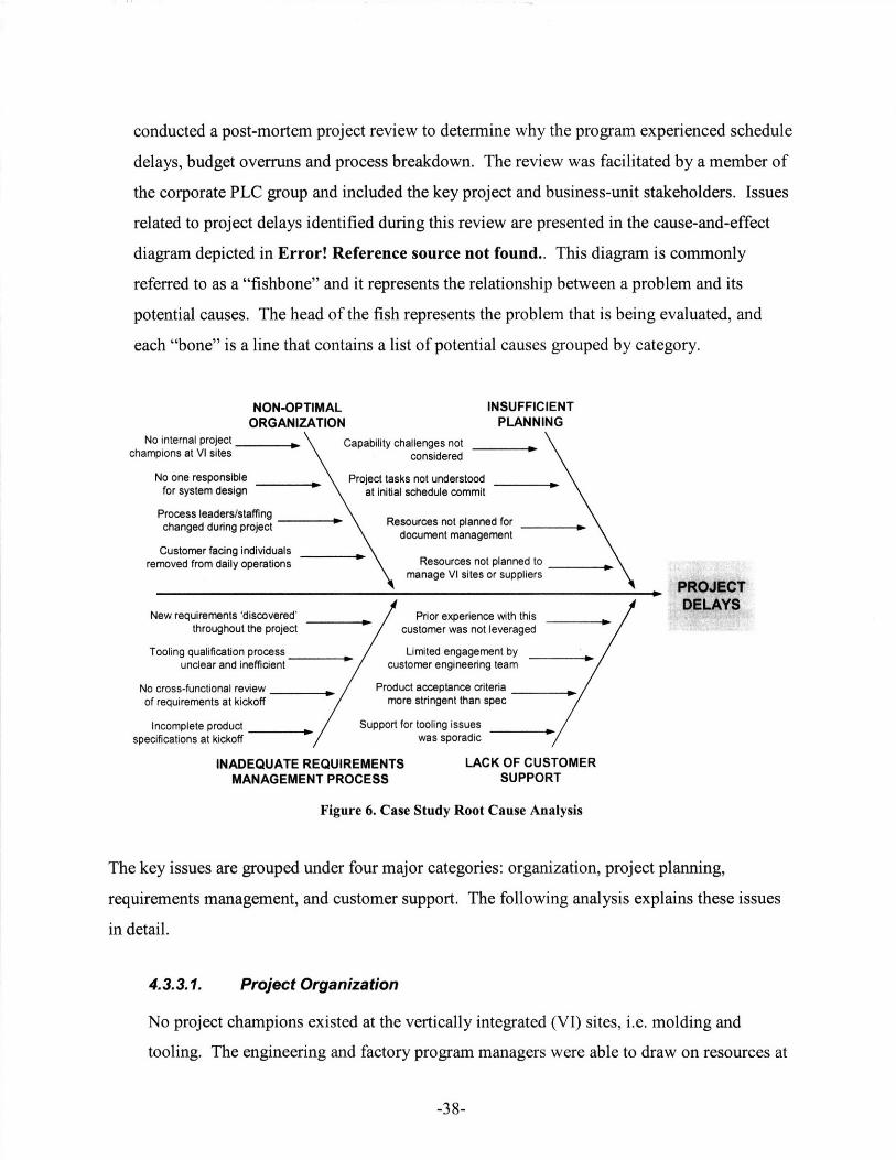
conducted a post-mortem project review to determine why the program experienced schedule
delays, budget overruns and process breakdown. The review was facilitated by a member of
the corporate PLC group and included the key project and business-unit stakeholders. Issues
related to project delays identified during this review are presented in the cause-and-effect
diagram depicted in Error! Reference source not found.. This diagram is commonly
referred to as a "fishbone" and it represents the relationship between a problem and its
potential causes. The head of the fish represents the problem that is being evaluated, and
each "bone" is a line that contains a list of potential causes grouped by category.
NON-OPTIMAL INSUFFICIEIORGANIZATION PLANNINC
No internal project , Capability challenges notchampions at VI sites considered
No one responsible Project tasks not understoodfor system design at initial schedule commit
Process leaders/staffingchanged during project . Resources not planned for
document managementCustomer facing individuals
removed from daily operations Resources not planned tomanage VI sites or suppliers
New requirements 'discovered' Prior experience with thisthroughout the project customer was not leveraged
Tooling qualification process Limited engagement byunclear and inefficient customer engineering team
No cross-functional review Product acceptance criteriaof requirements at kickoff more stringent than spec
Incomplete product Support for tooling issuesnnr.ificntitnn at kicrknff was sooradic
NT
PROJECTDELAYS
INADEQUATE REQUIREMENTS LACK OF CUSTOMERMANAGEMENT PROCESS SUPPORT
Figure 6. Case Study Root Cause Analysis
The key issues are grouped under four major categories: organization, project planning,
requirements management, and customer support. The following analysis explains these issues
in detail.
4.3.3.1. Project Organization
No project champions existed at the vertically integrated (VI) sites, i.e. molding and
tooling. The engineering and factory program managers were able to draw on resources at
-38-
~~~-~~--~-~-~

each of the sites in order to accomplish project goals, but no one was dedicated to the job
from beginning to end. This became an issue when the injection-molding tool was
traveling between the sites to be adjusted to meet requirements. A program manager at the
tooling facility reported that in one instance "the tool sat on [the injection molding plant's]
doorstep for up to three days before anyone touched it".
There is no one responsible for system-level design. Again, engineering program
management was able to draw on experienced and capable engineers from various
functional departments. However, functional engineers were sometimes new to the
organization and did not have integration experience. When integration issues arose, the
program manager was called upon to resolve the issues. Design integration occurred after
functional designs were completed so related adjustments were iterative instead of
concurrent. This led to a number of engineering design changes late in the process, during
the design validation testing phase.
Process leaders were discontinuous through the project as part of the process design. The
process dictates that the engineering program manager leads the project beginning in the
concept phase, which the design team is chosen. As the process leader for the
feasibility/opportunity portion of the process, the account manager had communications
with the customer that affected the engineering and factory team before they were formed.
Team member turnover also occurred during the course of the project. In each instance,
project-related knowledge was lost. Decisions were made, specifically with regard to tool
design, that would have been made differently if the team was privy to knowledge held by
team members that had moved on to other projects. As a result, tool rework was necessary.
Account managers remained in contact with the customer throughout the project, but were
based in the U.S., in addition to the lead engineers who possess platform knowledge and
who were often the more senior members of the design organization. Any time the
engineers in Asia had a question, they used email or telephone to communicate it to lead
engineers, account managers or business unit leaders in the U.S. Customer information
was relayed back to team members in the same fashion. In the dynamic environment,
-39-
sometimes key individuals found out information at different times depending on whether
they were included in particular emails.
4.3.3.2. Project Planning
The capability to meet customer requirements for injection-molded was not fully
understood when the schedule was created. The organization had to develop that capability
empirically during the product development effort through trial-and-error. Resources
were not allocated from the assembly plant to manage these issues and when they were
called upon to coordinate between the VI sites and solve these issues, their capacity to
perform project-related duties was reduced. The time required for other tasks related
specifically to ODM work were also not fully understood by the development team. For
example, sub-tier suppliers are typically managed by the customer for EMS projects,
however, now this relationship must be managed by the Client Company.
A new documentation initiative was put in place before this program, requiring all
engineering changes be document-controlled at EVT start. Discipline in documentation
was enforced more heavily on this project than in the past. This key initiative is part of
moving toward knowledge capture and management, but the engineers did not anticipate
the time it would take them to document their work. In addition to coping with an
aggressive development schedule, the engineers found it difficult to keep up with the
resultant workload. The factory noted that their requests for DFM-related engineering
changes were not returned promptly and that engineering change orders (ECOs) often
contained mistakes.
4.3.3.3. Requirements Management
At project kick-off, there was no cross-functional review of the requirements even though
the process called for it. The design team discovered that the requirements for the product
were incomplete well into the development effort, after the prototype delivery dates were
promised to the customer. Turnover over the course of the project and customer
interactions that resulted in undocumented requirements changes, requirements slipped
through the cracks.
-40-
Sometimes requirements were 'discovered' throughout the project. With respect to the
injection-molding issue, the customer clarified a key injection-molding requirement during
the development process but the information did not reach the tooling design team. A
member of the manufacturing team noted, "I don't know who knew this requirement
changed, but this would have been a lot easier if we had designed the tool properly in the
first place." The tool could have been designed differently from the outset to satisfy the
more stringent requirement. Because the true requirements for the injection-molded
components were learned through trial and error during product development, the
development team reworked the mold until the components met the customer's
requirements.
The tooling qualification process between the injection-molding facility and the tooling
facility was unclear and inefficient. As a result the balance between the molding process
specifications and tooling design and development could not be managed properly.
Particular testing and analyses to be conducted by the tooling facility to facilitate molding
process design was not carried out. Responsibility for meeting end-product requirements
was not clearly assigned. The ambiguity in this part of the process complicated the rework
activities associated with meeting end-product requirements.
4.3.3.4. Customer Support
The design team reported that the customer did not provide support for the level of
development issues the Client Company was experiencing. However, the customer did not
allocate engineering resources to support the Client Company because the company was a
second source and thus they did not expect the company to have capability problems.
Unplanned capability development coupled with little support from the customer
contributed to the nature of the tooling issues and also to the multiple customer-initiated
iterations on the injection-molded components.
The customer did provide ad-hoc engineering support for the molding and tooling issues.
However, the customer's engineering team did not share best-practices toward meeting
-41-

their relatively subjective requirement with the Client Company. Some employees from
other business units have had experience with this customer before, but it was not
leveraged on this project. Therefore, the time associated with the experimental nature of
meeting this customers' requirements was not calculated into the original schedule.
-42-

5. Enterprise Architecture Analysis
The following section examines the current state of the enterprise using the enterprise views as
defined by Nightingale and Rhodes. The focus of this analysis is to highlight enterprise issues
associated with TTM during development and NPI of the product.
5.1.1. Strategy
The primary objective of corporate headquarters is revenue growth and therefore it is the
primary objective of the business unit. This enterprise aspires to be the leading provider of
its product across the industry. Currently it is specifically targeting the high-growth
telecommunications, computing and mobile-device segments. Fast TTM is critical to
achieve a competitive advantage in this environment. Low cost is also a key factor because
the product is considered a commodity to OEMs. As the organization grows, scalability and
repeatability are important strategic considerations.
The enterprise supports an ODM business model and contributes to the Client Company's
vertical integration initiative. Prior to market entry by the Client Company, very little design
or manufacturing process innovation had been developed for this product industry-wide and
there was one major ODM player that held the majority of the market for this component.
The business employs internal tooling and molding facilities whenever possible in support of
the corporate strategic goal of vertical consideration. Strategic decision making occurs at the
top levels of the enterprise. Although business units retain a lot of latitude in decision
making, the CEO has the power in the organization. Strategic meetings between engineering,
operations, and manufacturing leadership occur on an ad-hoc basis, as issues arise. In
addition, the enterprise leadership participates in a bi-annual company-wide leadership
summit.
5.1.2. Process
Because the enterprise is currently in a growth mode, the majority of the processes by which
the enterprise creates value for its stakeholders are not currently documented. Prior to launch
-43-
of the first product, the CTF worked closely with cross-functional teams within the enterprise
to develop a tailored product life cycle process. In general, the process is designed to be
collaborative across functions, sites, and departments. The process requires participation of
employees globally across the business unit. Senior leadership owns the process. They may
opt to utilize resources from the PLC group to develop and improve the tailored process.
The documented development process is not available on the company intranet. It is
frequently out-of-date because the true process evolves each time a product development
cycle is completed and the organization learns. The development process is documented as a
PowerPoint file on a central server. Process documentation includes functional
responsibility, inputs, outputs and activities for consideration for each phase. The document
is visibly posted in engineering facilities and supplied via email to new engineers hired to
work at the company. Other than performance to schedule, development process
performance is not measured by the organization.
Because process flows are not documented in the product life cycle process and project tasks
required for phase gate exit are not always enforced by management. Also, roles and
responsibilities are not clearly defined and documented. Entry from one phase to the next
often does not signify a particular design progress level; rather it indicates that the customer
has approved the prototype supplied to them at the end of the phase. Often, the factory
proceeds to the next phase even though the design is not as mature as they expect it to be.
These issues have caused miscommunication on task responsibilities. Customer deliverables
are sometimes overlooked as a result of these miscommunications.
5.1.3. Product/Services
The organization employs a platform strategy with steady improvements of the platform. To
its customers, the enterprise provides integrated design, testing, manufacturing and supply
chain services for its products. The design capability enables OEMs to leverage the product
platforms already developed by the Client Company to minimize design variation, accelerate
-44-

TTM, and to utilize DFM and realize cost benefits. The Client Company's manufacturing
organizations support the flexible, high-volume production environment for these products.
The 6 to 9 month lifecycle for this product is getting shorter as the organization learns.
Unencumbered by capital that supports antiquated manufacturing processes technology, the
Client Company was in a position to develop a product platform that leverages its expertise
in advanced packaging technology and manufacturing excellence to develop a
technologically superior and lower cost product. It includes internal electronic circuitry and
some versions contain an injection-molded external enclosure.
5.1.4. Organization
In general, the organizational culture would be characterized as evolving, globally dispersed,
highly entrepreneurial and flat. The development organization is highly flexible and is able
to respond easily to short-term market dynamics as well as long-term market needs. In order
to obtain design expertise and to keep up with growth, the company continues to hire
engineering talent from existing ODM and OEM companies. Most engineers had been with
the company for less than 2 years but had been in the industry for over 8 years.
Manufacturing talent came from other product areas and business units within the Client
Company who were mostly familiar with the EMS model.
Day-to-day operational decisions are made locally and information is passed on an informal
basis. Program-level decisions often involve the site leaders and senior leadership.
Communication is typically done via email because every product team is dispersed globally.
Teams are highly self-directed. Senior leadership is quick to step in when a problem arises
and there is a clear decision making hierarchy in this case. Even the smallest issues tend to
be elevated to senior leadership.
The organization is largely functional in nature. Design, manufacturing, tooling, molding
and assembly are all done within the four walls of the Client Company for each customer, in
accordance with the Client Company's vertically-integrated ODM strategy. Although
organization charts exist, the organization is growing and changing so quickly that they are
-45-

often outdated. Turnover frequently occurs during programs. There is no responsible person
or design team that leads the project from beginning to end. There is no responsible team
that is in close communication from beginning to end.
The business unit president is based in the U.S. He is focused on working closely with the
CTF management to determine the strategic direction of the organization. Reporting to the
president are two key leaders: The Sr. Director of Operations, based in the USA and the
General Manager who is based at the PCB assembly facility. Like much of the leadership at
the Client Company, both hold multiple "full-time jobs on a part-time basis." They are both
heavily involved both in setting the strategic direction of the organization, developing
program management talent across the enterprise, and providing leadership direction on key
accounts. The Sr. Director of Operations travels to the various sites extensively, including
the vertically integrated support sites, namely tooling and injection molding. When problems
arise on key accounts, both leaders are typically knowledgeable about technical operational
issues and are heavily involved with problem resolution and communication with the
customer. Many of the lead engineers and account managers reside in the USA while the
engineering program managers and functional engineers reside in Asia.
The engineering program management function is not well-defined and does not have
organizational control over the resources assigned to his project. This individual also tends
to be a very experienced engineer. In the entrepreneurial environment, he will contribute
where his skills are most useful, and as such he will be involved with system level design
integration, chasing parts, and problem resolution. All of these unplanned activities serve as
interruptions to the program manager, taking his attention away from program management.
5.1.5. Knowledge
Currently, knowledge management processes are informal and undocumented. The culture
around sharing knowledge is very open and there are few boundaries to new knowledge. A
lesson learned is likely to be acted upon and incorporated if one can find it. Only
experienced engineers are hired for development activities, and some of the most
experienced and knowledgeable engineers tend to take the role of engineering program
-46-

manager. They help functional engineers integrate the design and to perform their functional
roles. Knowledge is largely tribal, with no formal repository for lessons learned. Project-
related learning is not typically documented and distributed across the organization because
all the resources that are available are dedicated to meeting already aggressive project
schedules. Engineers report that they do not have time to document learning. New engineers
are generally immediately assigned to new projects without training material or engineering
best practices available for the on-boarding process.
Many engineers pointed out that they were immediately staffed on a project the day they
arrived. Although most had more than eight years of experience in their related fields, they
did not yet understand the organization and were not able to leverage institutional knowledge
that resided within the organization. Some engineers joined the company mid-project, and if
turnover had occurred they did not know who to contact to get necessary information.
Engineers noted that improvement opportunities are identified each time a prototype is tested
but because the focus is getting the prototype to the customer, documentation of these
opportunities is a low priority. As such, there is no body of product knowledge from which
to draw.
Learning does not get institutionalized and therefore it is difficult to improve at an
organizational level. In addition, engineering talent is obtained from other companies and
each new employee brings his own assumptions about roles and responsibilities. This adds
another element of complexity to the team environment because no formal training exists for
individual contributors. Assumptions must be made and certain tasks tend to fall through the
cracks. This often places the engineering program manager in a position to fill in the
responsibility gaps.
5.1.6. Information
Much effort has been put into the IT architecture during the evolution of the business unit,
and it is continuing to evolve. The enterprise uses commonly shared software applications a
repository for all product-related documentation. Project information is divided by customer,
including BOMs, engineering change orders (ECOs), manufacturing change orders (MCOs),
-47-
test data, drawings, specifications, gate reviews, etc. The change management process is
tightly controlled, with a requirement that all design changes be recorded.
Day-to-day communication is typically done via email or telephone. Employees who are
accustomed to traditional modes of communication tend to use them to transfer project
related information. Engineers often circumvent the ECO process by e-mailing design
changes to the manufacturing organization. Many documents are stored on local servers
instead of in centralized locations designed for project documentation.
5.1.7. Policy/External Factors
The products are produced in one of the "Special Economic Zones" (SEZs) of Asia, where
the government has developed special economic policies and flexible measures for SEZs that
make it conducive to doing business. However, there are some special challenges that come
along with being a new industry player conducting product development in Asia. First, the
Client Company must buy smaller quantities at higher prices than would the entrenched
competition because the local culture is relationship-based. This will remain a challenge
until the Client Company can offer guaranteed volumes, or large volumes, and a relationship
is developed with the local supply base. Some employees may have familial or professional
relationships with members of the local supply base. Because corporate-level relationships
are still being developed and there are time pressures to execute on projects, whoever has the
relationship negotiates the price and maintains the relationship with the supplier. Second,
employee turnover is a large issue in these regions because companies compete fiercely for
experienced engineering and manufacturing personnel. Each time an employee leaves the
company, they bring with them key knowledge and information that has likely not been
institutionalized.
In new markets, the Client Company is typically brought on as a second source to allow the
OEM to evaluate the company's capabilities at low risk. In this case, there is little risk to the
customer if the company launches late. As a second supplier, the customer expects that the
process should be as easy as the "flip of a switch". As a result, the customer rarely allocates
-48-

engineering resources to support the project and cannot provide the level of engineering
support the Client Company would need if there is a capability concern.
Because competition is fierce, aggressive and unrealistic schedules are common. Industry
norms dictate an accelerated quoting process which includes prototype delivery schedules.
Project teams often meet customer-driven prototype delivery schedules, but if a project is
behind, the some of the supporting information required to move to the next phase is either
neglected or incomplete. This leads to design rework later in the process because the
information may have led to alternate design decisions. It also leads to overload for
engineering because the information neglected early in the process must still be created to
launch the product, on top of the normally scheduled project activities. Overload tends to
lead to further mistakes.
The EMS culture is cost-focused and the Client Company in particular has very low overhead
expenses compared with other companies in the industry (SG&A less than 3% of sales). This
puts severe limitations on investment in improvement or process development and
contributes to a locally cost-optimized mindset. For example, there are many IT
improvements that are generally used industry-wide; however, they are not implemented due
to their cost. It is arguable that these improvements (such as a standard parts database) could
reduce mistakes, encourage use of standard components and improve inventory. However,
the funding for an effort such as this one is being allocated to obtaining resources needed to
execute current and future projects.
Vertically integrated resources, such as tooling and injection-molding, are still evolving
organizationally. These organizations have P&L responsibilities as well, so business units
often have to fight for resources. Naturally, they will be most responsive to their largest
customers, even though they are all internal. As a result, a project that is strategic in nature
to the growth of a business unit may not get the attention it requires from the tooling or
molding facilities.
-49-

6. Product Development Waste in the Current State
The enterprise architecture analysis presented highlights some of the key issues with conducting
ODM development in a globally dispersed environment with development and manufacturing in
Asia. The development process in this environment can be characterized by ambiguity and
volatility, as observed in the case study. Many of the issues observed can be attributed to the fact
that the enterprise is quickly evolving and will be resolved through organizational learning. It
can also be attributed to the changing business landscape as OEMs adjust to working with EMS
providers as ODMs. The following discussion highlights product development waste associated
with the current state of the enterprise.
6.1. Scatter
Scatter is defined as "actions that make knowledge ineffective by disrupting its flow," and
"disrupts the subtle interactions required for teamwork6." The following discussion addresses
the sources of scatter in the development environment of this enterprise at the Client Company.
Organizational roles are influx. New development team members are experienced individuals
who are accustomed to the norms of their previous experiences, and carry with them varied
assumptions of their role within the development team. The process of working together as a
team and knowing who is part of the team is currently a moving target. Inevitably, important
tasks fall through the cracks causing design rework later in the development process. Team
members have trouble navigating their way through the system to resolve issues because
responsibilities are not evident in the organizational structure.
Process definition is still influx. Project managers cannot estimate how long a project will
take if the necessary steps are not defined. No team member has proper tools at their disposal
to understand the scope of their activities on a given project. Without knowledge of and
adherence to process flows, design decisions could be made based incomplete information
causing rework later on as evidenced in the case study. In short, a realistic schedule cannot be
created without an understanding of process flow. An additional challenge with defining
-50-
process is that each customer expects different information at different times, so processes
often have to be tailored by product and by customer.
Globally dispersed development teams. Engineering development occurs in both the USA and
in Asia and is not collocated with manufacturing. Business unit leadership, account managers
and lead engineers, who often pitch in to resolve project issues, are also located in the USA. In
addition to the language and cultural barriers associated with working on an international
project, just the time associated with waiting for answers to questions across continental time
zones can hinder progress.
6.2. Hand-Off
Handoff occurs when knowledge, responsibility, action and feedback are separated 6. Handoff
is a problem in organizations because it "results in decisions being made by people who do not
have enough knowledge to make them well or the opportunity to make them happen6." The
following discussion addresses the sources of handoff in the development environment of this
enterprise at the Client Company.
Limited collaboration with OEMs. The current mindset of OEMs toward EMS suppliers is that
they are "build-to-specification" organizations. Even for ODM work, the EMS supplier is
often called upon as a second source especially when they are not yet proven in a particular
market. As a result, the OEM provides limited engineering resources toward defining product
requirements and resolving engineering issues. Sometimes, key design and production
knowledge resides with the OEM, but responsibility and action reside with the EMS provider.
Siloed organizations. Many resources act as profit-and-loss centers and lack visibility or
incentive to prioritize to company strategy. Functional managers (e.g. engineering, tooling,
molding) are not held responsible for supporting project leaders. Rather, they are responsible
for maximizing profit for their organizations. Project leaders in growing organizations often
have to fight for resources with larger projects, even when their project is aligned with a key
strategic customer. Responsibility for achieving results of resolving issues can easily be
passed around, delaying action on key projects.
-51-

Process definition and enforcement is a staiffunction. The process knowledge actually resides
within the business unit, but responsibility for defining and maintaining the process lies with
the PLC organization even after business units are spun off. Business unit leaders are not held
accountable for development process performance and project leaders are not held responsible
for adhering to the process. Inadequate process definition and circumvention of the process is
still common, causing an early switch into firefighting mode on many projects.
6.3. Wishful Thinking
Wishful thinking is defined as making "decisions without data or operating blindly6 ." Included
in this category is discarding knowledge gained through product development cycles. The
following discussion addresses the sources of wishful thinking in the development
environment of this enterprise at the Client Company.
Price-focused competitive bidding. Given the fierce competition amongst EMS suppliers for
work OEMs tend to focus on achieving the best price for their products. Limited margins for
EMS companies prohibit investment in capability and process improvements. Many times,
negotiations are conducted between sales personnel without engineering involvement. As a
result, the capabilities required to execute a project are not clearly understood when the
schedule is committed. Capability development through product development then occurs,
causing schedule delays and sucking resources from other product development projects.
Resources not available for knowledge capture. Project teams are focused solely on getting
the product out and testing to the specifications for the specific project. This limits the ability
of the organization to turn data generated on projects into useful knowledge. The organization
is growing fast, so new people coming in next month will not benefit from knowledge gained
today. This hinders the organization's ability to capitalize on the wealth of knowledge gained
through completing multiple product development cycles every year as well as from the
experienced personnel at their disposal.
-52-
7. Recommendations
Improvement areas are focused around scalability and repeatability of the development process.
As seen in the case study, more coordination is required to execute properly as the organization
scales up. Repeatable execution cannot occur if learning is not institutionalized and knowledge
is not captured, especially in a growth environment as new, experienced employees are being
hired systematically from other organizations. Rapid growth is a major contributor to
organizational and process challenges. As the enterprise matures and learns, many of these
issues will naturally improve. The recommendations provided here suggest the use of lean
product development tools and methods to aid in the improvement efforts that are already being
pursued by the management team. They are categorized according to the enterprise views that
are most importantly addressed in achieving the strategic goal of accelerating TTM.
7.1. Process
The enterprise should first document the process flows as they are executed on an upcoming
development project in order to create a process map including process flows. Process
mapping is key to understanding the current state of the development process. This effort will
reduce scatter in product development because it will enable the organization to more
accurately provide program schedules and plan resources for projects more effectively. It will
also reduce ambiguity during the development process by providing the program manager a
means to assign project tasks, clarifying roles and responsibilities for a given project. Mapping
the process as it happens during a development process minimizes resources used to document
the process and it captures the actual flows associated with development.
Ownership of and process definition and accountability for process performance should be
delegated to the enterprise rather than the PLC group soon after the business is spun off. This
will encourage process ownership and raise the level of commitment to process fidelity within
the enterprise. The process that is chosen must fit with the culture of the organization, which
in this case is highly entrepreneurial. Another special aspect to consider is the tailoring
required for individual projects as each customer has its own development process that dictates
-53-

when deliverables are needed from the Client Company. Enforcement of the process should be
focused on key gate checkpoints, and leave flexibility for highly-developed product
development teams to conduct the day-to-day activities.
7.2. Organization
The first organizational recommendation is to develop teams of responsible experts that carry a
project from beginning to end including members of the vertically integrated organizations
(molding and tooling). Essentially everyone on the team, especially those that manage the
project, would be dedicated to each project from beginning to end. Ideally, teams would
continue to work together over multiple NPI cycles and as a result develop expertise as a
group. This recommendation would reduce project delays associated with handoff due to
organizational silos and also may mitigate the negative effects of a globally dispersed product
development organization. This concept could be implemented for a pilot program at no cost.
Another consideration would be to collocate all engineering resources with manufacturing to
enable close collaboration between groups during the development process. This would also
encourage lead engineers to mentor and teach junior engineers throughout the process. It
would mitigate program delays normally associated with a globally dispersed environment,
further reducing waste associated with handoff.
7.3. Knowledge
In order to become faster and more efficient as an organization, opportunities for improvement
should be documented and shared. Doing this effectively could provide a tremendous
advantage for the Client Company because the rate at which the organization learns would be
proportional to the product development life cycle, which in this case is typically less than 9
months.
-54-

8. Conclusion
This study serves to highlight the current state of a top EMS supplier pursuing ODM contracts.
The current state reveals ambiguity associated with growth through acquisition and internal
capability development. As the business landscape changes, the Client Company can be
expected to become more strategic about customer and project selection and to pursue more
ODM and joint-development ventures. OEMs will be more willing to collaborate with the Client
Company as the EMS market consolidates and less choice exists amongst EMS suppliers.
The employees at the Client Company all exhibit a clear dedication to creating value for
customers. It is important to note that the capability gaps demonstrated in this study are not due
to a lack of ability of the individuals doing the work or running the business. Entrepreneurial
energy is a core aspect of the corporate culture at the Client Company, and in particular, new
business units such as the one observed in the case study. Because the Client Company is a
service-oriented organization, there is an overwhelming culture of saying "yes" and then
creatively finding a way to deliver on the commitment later. This is in tension with the level of
strategic planning and coordinated business processes required for a mature organization.
Many of the recommendations mentioned here will be implemented at the Client Company as the
company begins to invest in improvement. The key to sustaining improvements lies in the
behaviors of the enterprise, namely responsibility, teamwork, and expertise through continuous
learning. Whereas the current system rewards heroes who 'get the job done' and who turn a
profit for their functional organization, the new management system s reward employees who do
what they say they will do, take responsibility for success of projects as a whole, and continue to
develop their expertise over time.
-55-

This page has been unintentionally left blank
-56-

Endnotes
1 Roberts, B. Benchmark study shows ODM industry still stronger than EMS industry. EMSNow. Retrieved March
6, 2008, from http://www.emsnow.com/npps/story.cfm?id=27914.2 Dissecting the new Flextronics. VentureOutsource.com. Retrieved April 6, 2008, from
http://www.ventureoutsource.com/contract-manufacturing/industry-pulse/2/2008/dissecting-the-new-flextronics.
3 Dean, J. (2007, August 11). The Forbidden City of Terry Gou [Electronic Version]. The Wall Street Journal.
Retrieved April 15, from http://online.wsj.com/public/article/SB 118677584137994489.html
4 The Info Tech 100. (2007, July 2). Business Week. Retrieved April 10, 2008, from
http://www.businessweek.com/magazine/content/07_2 7/b4041408.htm
5 Ulrich, Karl and Steven Eppinger. (2004). Product Design and Development. McGraw-Hill/Irwin.6 Ward, A. C. (2007). Lean Product and Process Development. Cambridge, MA: Lean Enterprise Institute.
7 Morgan, J. M. & Liker, J. K. (2006). The Toyota Product Development System. Productivity Press.
-57-