accelerated insertion of materials – · pdf fileaccelerated insertion of materials...
TRANSCRIPT
Presented at Penn State University
by Karl M. NelsonDeputy Program Manager Boeing Phantom Works
Accelerated Insertion of Materials – Composites
8 November 2002
Report Documentation Page Form ApprovedOMB No. 0704-0188
Public reporting burden for the collection of information is estimated to average 1 hour per response, including the time for reviewing instructions, searching existing data sources, gathering andmaintaining the data needed, and completing and reviewing the collection of information. Send comments regarding this burden estimate or any other aspect of this collection of information,including suggestions for reducing this burden, to Washington Headquarters Services, Directorate for Information Operations and Reports, 1215 Jefferson Davis Highway, Suite 1204, ArlingtonVA 22202-4302. Respondents should be aware that notwithstanding any other provision of law, no person shall be subject to a penalty for failing to comply with a collection of information if itdoes not display a currently valid OMB control number.
1. REPORT DATE NOV 2002
2. REPORT TYPE N/A
3. DATES COVERED -
4. TITLE AND SUBTITLE Accelerated Insertion of Materials Composites
5a. CONTRACT NUMBER
5b. GRANT NUMBER
5c. PROGRAM ELEMENT NUMBER
6. AUTHOR(S) 5d. PROJECT NUMBER
5e. TASK NUMBER
5f. WORK UNIT NUMBER
7. PERFORMING ORGANIZATION NAME(S) AND ADDRESS(ES) Boeing Phantom Works
8. PERFORMING ORGANIZATIONREPORT NUMBER
9. SPONSORING/MONITORING AGENCY NAME(S) AND ADDRESS(ES) 10. SPONSOR/MONITOR’S ACRONYM(S)
11. SPONSOR/MONITOR’S REPORT NUMBER(S)
12. DISTRIBUTION/AVAILABILITY STATEMENT Approved for public release, distribution unlimited
13. SUPPLEMENTARY NOTES The original document contains color images.
14. ABSTRACT
15. SUBJECT TERMS
16. SECURITY CLASSIFICATION OF: 17. LIMITATION OF ABSTRACT
UU
18. NUMBEROF PAGES
63
19a. NAME OFRESPONSIBLE PERSON
a. REPORT unclassified
b. ABSTRACT unclassified
c. THIS PAGE unclassified
Standard Form 298 (Rev. 8-98) Prescribed by ANSI Std Z39-18

Acknowledgements
AIM-C is jointly accomplished by a BOEING Led Team and the U.S. Government under the guidance of NAST
AIM-C is funded by DARPA/DSO and administered by NAST through TIA N00421-01-3-0098.
We acknowledge the support of Dr. Steve Wax and Dr. Leo Christodoulouof DARPA/DSO. The NAVAIR Technical Monitor is Dr. Ray Meilunas.
Also:Gail Hahn (PM), Charley Saff (DPM), & Karl Nelson (DPM) - Boeing Corp.
AIM-C Team - Boeing (St. Louis, Seattle, Canoga Park, Philadelphia), Northrop Grumman, Materials Sciences Corporation, Convergent Manufacturing Technologies, Cytec Fiberite, Inc, Massachusetts Institute of Technology, Stanford & NASA (Langley)
P4P3P2P1
C3C2C1
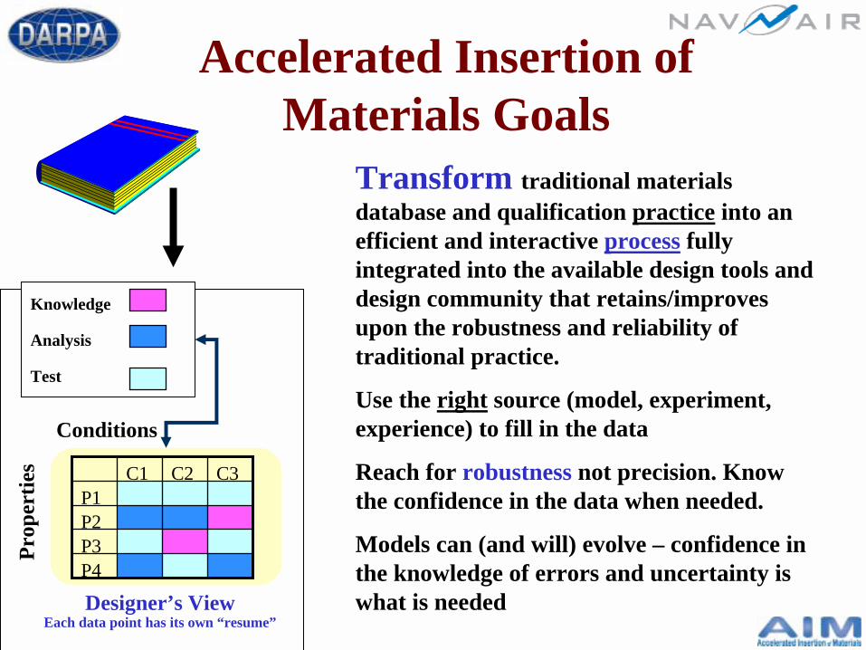
Accelerated Insertion of Materials Goals
Designer’s ViewEach data point has its own “resume”
Conditions
Prop
ertie
s
Test
Analysis
Transform traditional materials database and qualification practice into an efficient and interactive process fully integrated into the available design tools and design community that retains/improves upon the robustness and reliability of traditional practice.
Use the right source (model, experiment, experience) to fill in the data
Reach for robustness not precision. Know the confidence in the data when needed.
Models can (and will) evolve – confidence in the knowledge of errors and uncertainty is what is needed
Knowledge
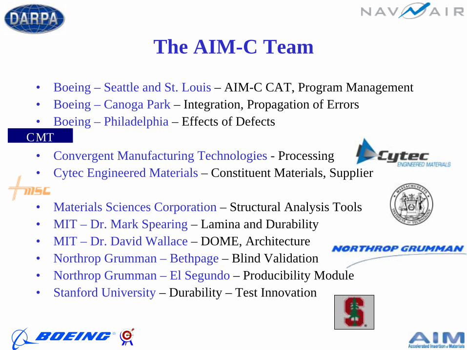
The AIM-C Team
• Boeing – Seattle and St. Louis – AIM-C CAT, Program Management• Boeing – Canoga Park – Integration, Propagation of Errors• Boeing – Philadelphia – Effects of Defects
• Convergent Manufacturing Technologies - Processing• Cytec Engineered Materials – Constituent Materials, Supplier
• Materials Sciences Corporation – Structural Analysis Tools• MIT – Dr. Mark Spearing – Lamina and Durability• MIT – Dr. David Wallace – DOME, Architecture• Northrop Grumman – Bethpage – Blind Validation• Northrop Grumman – El Segundo – Producibility Module• Stanford University – Durability – Test Innovation
CMTCMT
Outline
• Introduction to AIM– Why AIM is Important– Technical Approach– Modeling Architecture– Methodology– Designer Needs
• Sample Problem 1– Cure Hardening Behavior
of Epoxy• Sample Problem 2
– A Zero CTE Laminate
• Sample Problem 3– Cure Cycle Development– Processing Properties– Exotherm– Residual Stresses
• Design of Complex Structure – Hat Stiffened Panel
• Conclusions/Summary
Understanding the Current ProcessWhy We Test
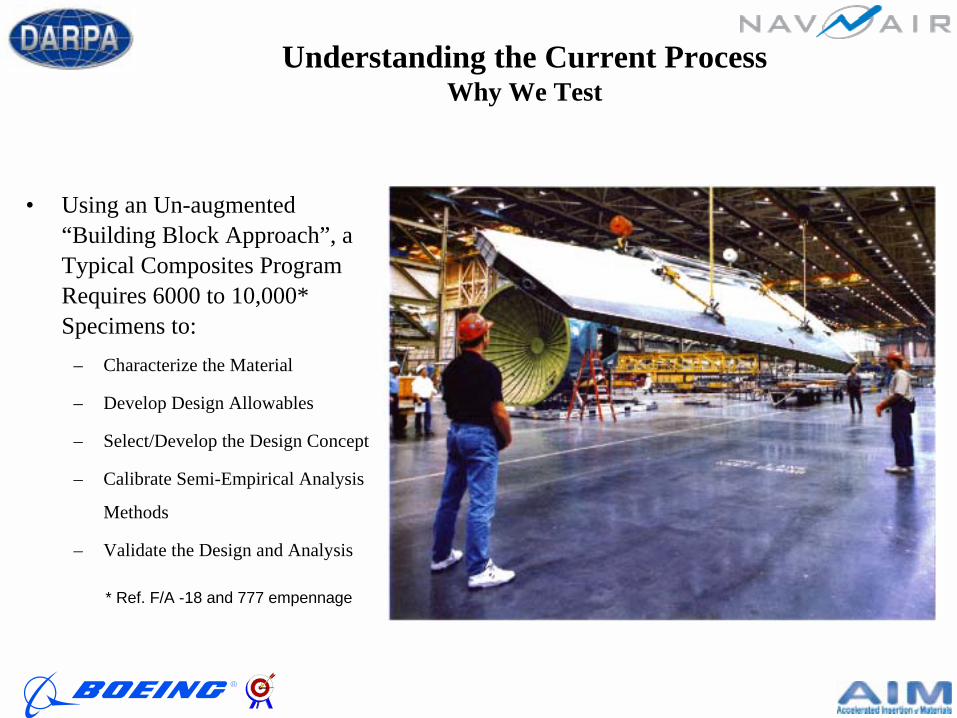
• Using an Un-augmented “Building Block Approach”, a Typical Composites Program Requires 6000 to 10,000* Specimens to:
– Characterize the Material
– Develop Design Allowables
– Select/Develop the Design Concept
– Calibrate Semi-Empirical Analysis
Methods
– Validate the Design and Analysis
* Ref. F/A -18 and 777 empennage
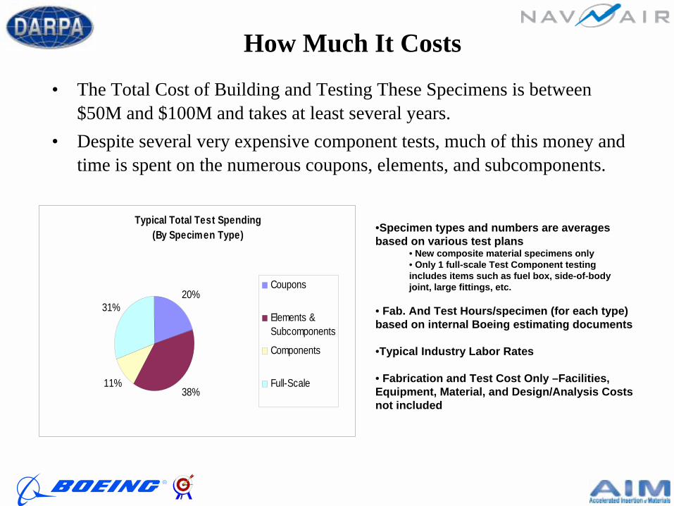
• The Total Cost of Building and Testing These Specimens is between $50M and $100M and takes at least several years.
• Despite several very expensive component tests, much of this money and time is spent on the numerous coupons, elements, and subcomponents.
•Specimen types and numbers are averages based on various test plans
• New composite material specimens only• Only 1 full-scale Test Component testing includes items such as fuel box, side-of-body joint, large fittings, etc.
• Fab. And Test Hours/specimen (for each type) based on internal Boeing estimating documents
•Typical Industry Labor Rates
• Fabrication and Test Cost Only –Facilities, Equipment, Material, and Design/Analysis Costs not included
How Much It Costs
Typical Total Test Spending(By Specimen Type)
20%
38%11%
31%
Coupons
Elements &Subcomponents
Components
Full-Scale

Boeing is the World’s Largest Manufacturer of Composite Aerospace Parts
• 4 Million Pounds Annually• ~ $300M Spent on Raw Material• We Add ~ 5 times to the value• $2B Annually Fly Away
Tooling Material
Recurring Tooling Support
Assembly Tools
Detail Tools for Composites
Assembly Labor and Materials
CFRP Detail Labor and Materials
406
104
102
133 20
18
0
100
200
300
400
500
600
700
800
900
1000
Total Dollars/ Lb.fly
-aw
ay c
ost p
er p
ound
of
com
posi
te s
truc
ture
$784
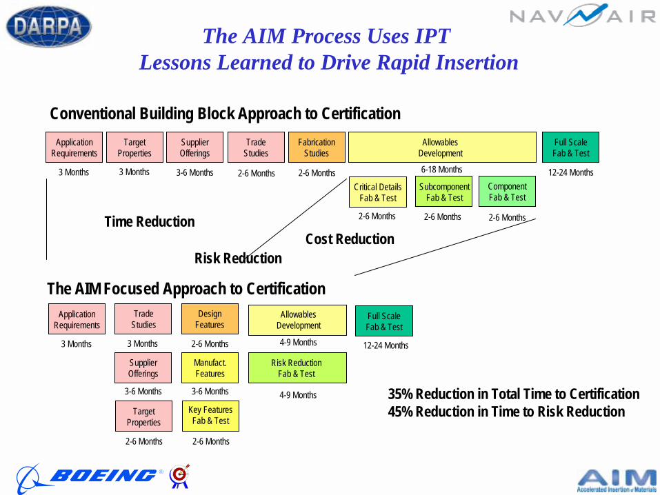
Application Requirements
Target Properties
SupplierOfferings
Trade Studies
FabricationStudies
Allowables Development
Critical DetailsFab & Test
SubcomponentFab & Test
ComponentFab & Test
Full ScaleFab & Test
3 Months 3 Months 3-6 Months 2-6 Months 2-6 Months
2-6 Months 2-6 Months 2-6 Months
12-24 Months6-18 Months
Application Requirements
SupplierOfferings
Trade Studies
Allowables Development
Risk Reduction Fab & Test
Full ScaleFab & Test
3 Months 3 Months
3-6 Months
2-6 Months
2-6 Months
4-9 Months
4-9 Months
35% Reduction in Total Time to Certification45% Reduction in Time to Risk Reduction
Manufact.Features
DesignFeatures
3-6 Months
2-6 Months
Target Properties
Key FeaturesFab & Test
The AIM Process Uses IPT Lessons Learned to Drive Rapid Insertion
Conventional Building Block Approach to Certification
The AIM Focused Approach to Certification
Time ReductionCost Reduction
Risk Reduction
12-24 Months
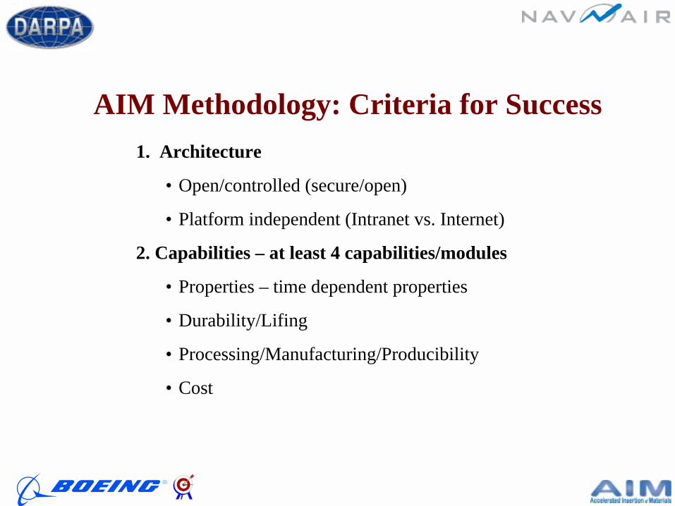
1. Architecture
• Open/controlled (secure/open)
• Platform independent (Intranet vs. Internet)
2. Capabilities – at least 4 capabilities/modules
• Properties – time dependent properties
• Durability/Lifing
• Processing/Manufacturing/Producibility
• Cost
AIM Methodology: Criteria for Success

3. Features/Outputs• Demonstrate that the methodology reproduces the DKB• Demonstrate that “a rogue” process spec will result in a flag by the
system• Demonstrate that a rogue “geometry” results in an “un-producible”
flag• Demonstrate the ability of the system to direct experiment – to direct
an experiment to determine a “benchmarking” parameter, or a basic physical quantity. (validation/calibration)
AIM Methodology: Criteria for Success
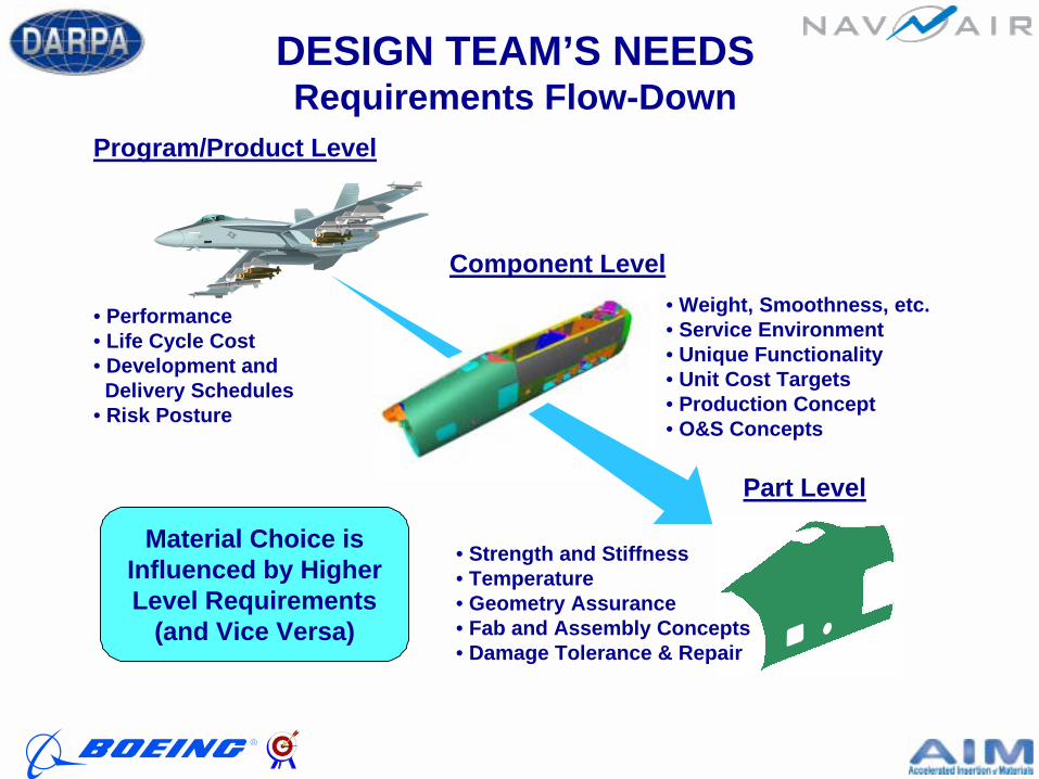
DESIGN TEAM’S NEEDSRequirements Flow-Down
Program/Product Level
Component Level
Part Level
• Performance• Life Cycle Cost• Development and Delivery Schedules• Risk Posture
• Weight, Smoothness, etc.• Service Environment• Unique Functionality• Unit Cost Targets• Production Concept• O&S Concepts
• Strength and Stiffness• Temperature• Geometry Assurance• Fab and Assembly Concepts• Damage Tolerance & Repair
Material Choice isInfluenced by HigherLevel Requirements
(and Vice Versa)
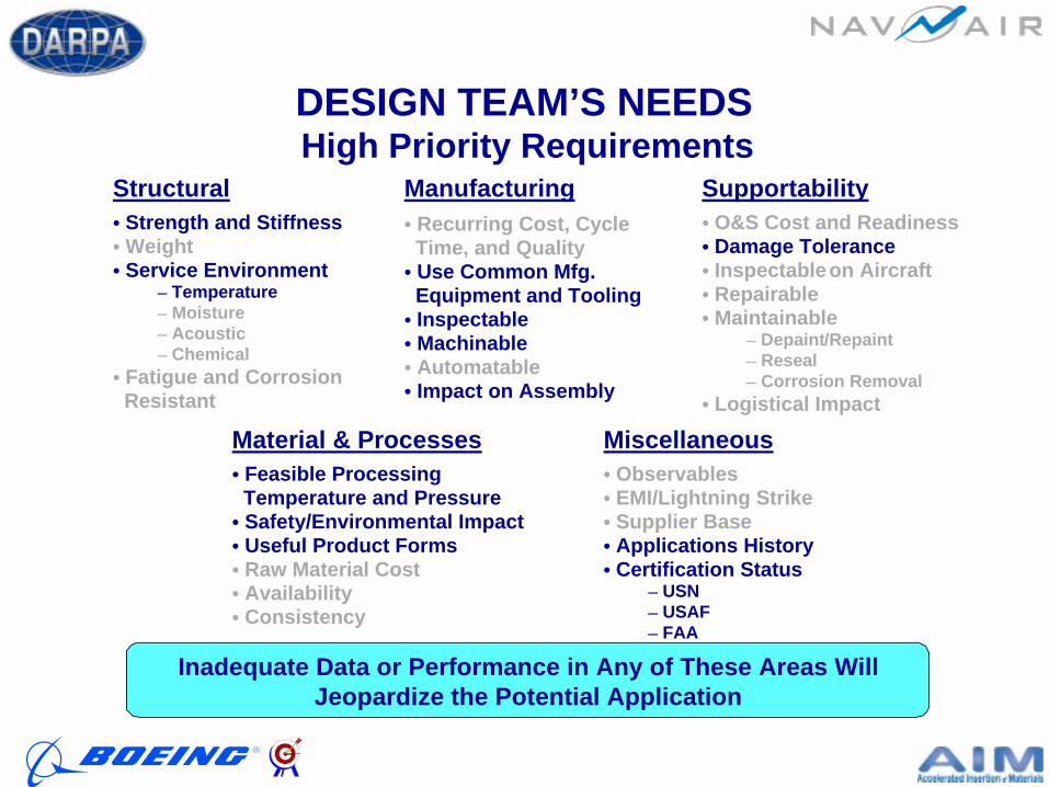
DESIGN TEAM’S NEEDSHigh Priority Requirements
Structural• Strength and Stiffness• Weight• Service Environment
– Temperature– Moisture– Acoustic– Chemical
• Fatigue and CorrosionResistant
Material & Processes• Feasible Processing
Temperature and Pressure• Safety/Environmental Impact• Useful Product Forms• Raw Material Cost• Availability• Consistency
Manufacturing• Recurring Cost, Cycle
Time, and Quality• Use Common Mfg.
Equipment and Tooling• Inspectable• Machinable• Automatable• Impact on Assembly
Supportability• O&S Cost and Readiness• Damage Tolerance• Inspectable on Aircraft• Repairable• Maintainable
– Depaint/Repaint– Reseal– Corrosion Removal
• Logistical Impact
Miscellaneous• Observables• EMI/Lightning Strike• Supplier Base• Applications History• Certification Status
– USN– USAF– FAA
Inadequate Data or Performance in Any of These Areas WillJeopardize the Potential Application
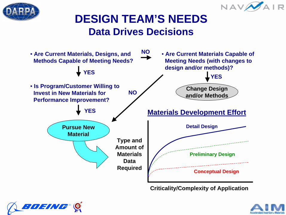
DESIGN TEAM’S NEEDSData Drives Decisions
• Are Current Materials, Designs, and Methods Capable of Meeting Needs?
YESYES
NO
• Is Program/Customer Willing to Invest in New Materials for Performance Improvement?
YES
Pursue NewMaterial
Change Designand/or Methods
• Are Current Materials Capable of Meeting Needs (with changes to design and/or methods)?
Criticality/Complexity of Application
Type andAmount ofMaterials
DataRequired Conceptual Design
Preliminary Design
Detail Design
Materials Development Effort
NO
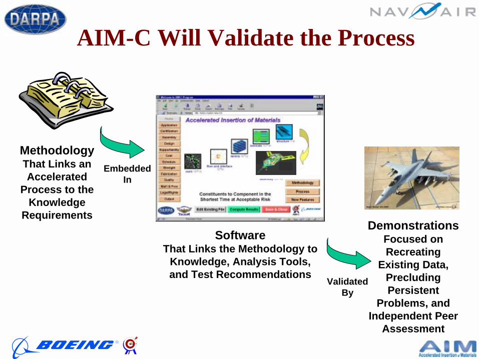
MethodologyThat Links an Accelerated
Process to the Knowledge
Requirements
SoftwareThat Links the Methodology to
Knowledge, Analysis Tools, and Test Recommendations
Embedded In
Validated By
DemonstrationsFocused on Recreating
Existing Data,Precluding Persistent
Problems, and Independent Peer
Assessment
AIM-C Will Validate the Process
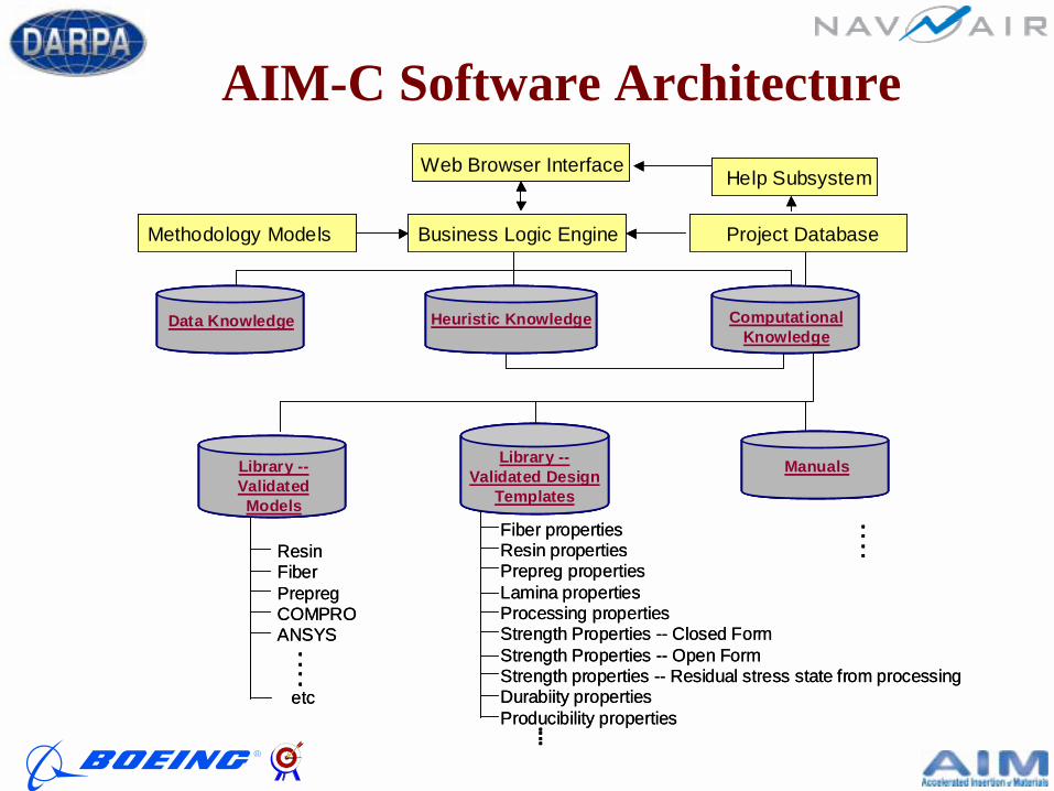
AIM-C Software ArchitectureWeb Browser Interface
Business Logic Engine Project DatabaseMethodology Models
Data Knowledge Heuristic Knowledge ComputationalKnowledge
Help Subsystem
Library --Validated Models
Library --Validated Design
Templates
Manuals
ResinFiberPrepregCOMPROANSYS
etc
....
Fiber propertiesResin propertiesPrepreg propertiesLamina propertiesProcessing propertiesStrength Properties -- Closed FormStrength Properties -- Open FormStrength properties -- Residual stress state from processingDurabiity propertiesProducibility properties....
....
Web Browser Interface
Business Logic Engine Project DatabaseMethodology Models
Data Knowledge Heuristic Knowledge ComputationalKnowledge
Help Subsystem
Library --Validated Models
Library --Validated Design
Templates
Manuals
ResinFiberPrepregCOMPROANSYS
etc
....
....
Fiber propertiesResin propertiesPrepreg propertiesLamina propertiesProcessing propertiesStrength Properties -- Closed FormStrength Properties -- Open FormStrength properties -- Residual stress state from processingDurabiity propertiesProducibility properties....
....
....
....
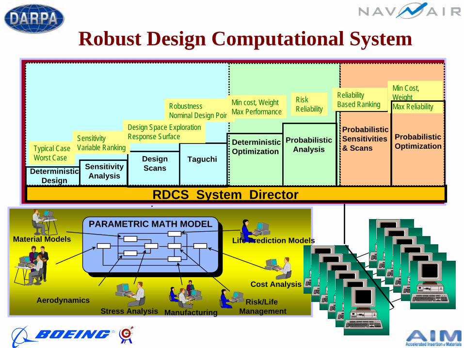
Material Models
Cost Analysis
Life Prediction Models
AerodynamicsStress Analysis
Risk/Life Management
PARAMETRIC MATH MODEL
Manufacturing
RDCS System Director
DeterministicOptimization
ProbabilisticAnalysis
ProbabilisticSensitivities& Scans
TaguchiDesign Scans
ProbabilisticOptimization
SensitivityAnalysisDeterministic
Design
Typical CaseWorst Case
SensitivityVariable Ranking
Design Space ExplorationResponse Surface
RobustnessNominal Design Point
Min cost, WeightMax Performance
RiskReliability
Reliability Based Ranking
Min Cost, WeightMax Reliability
Robust Design Computational System

The Oculus Integration SystemCOCOTMTM: A Plug & Play Modeling Environment: A Plug & Play Modeling Environment
CAM
Design
CAD
FEA
Structural Analysis
Cost
Manufacturing
Excel/
Databases
Req
uirem
ents
Dwg. Package
Perform
ance
Pricin
g
Pro
ducib
ility
Trade-offs
Pricing
Performance
Geometry
B.O.M.
Pricing
• Integrates Data and Software Applications on-the-fly
• Drag & Drop, Plug & Play
• Simple to create, modify, manage, maintain
• Enables Real-time data sharing between applications
• Secure
• Controlled
• Intra/Internet
• Platform Independent
• Distributed
• Neutral to Platforms and Applications
• Increases Value of Previous Investments
• Software
• Hardware
• Networks

WorksheetsXRL
TRL
AIM-C System Vision
Design Values
&Maturity
Inputs
RDCS MaterialsModule
StructuresModule
ProcessModule
Produc.Module
DurabilityModule
Certification
Cost
Materials
Module LinkageSystem - CO
Supportability
Legal/Rights
Schedule
Assembly
Application
DKB
Interface
Design
Producibility
Durability
M-VisionHeuristics
TestData
Strength
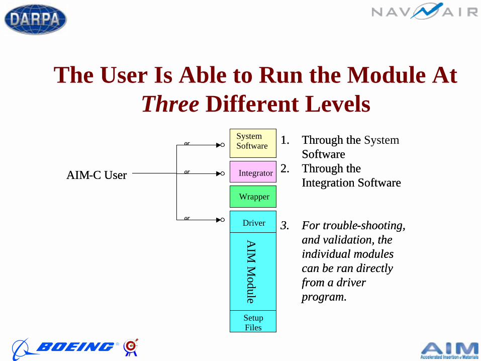
The User Is Able to Run the Module At Three Different Levels
AIM-C User
1. Through the Software
2. Through the Integration Software
3. For trouble-shooting, and validation, the individual modules can be ran directly from a driver program.
Umbrella Software
Wrapper
Integrator
AIM
Module
Driver
SetupFiles
or
or
or
AIM-C User
1. Through the System Software
2. Through the Integration Software
3. For trouble-shooting, and validation, the individual modules can be ran directly from a driver program.
Umbrella Software
Wrapper
Integrator
AIM
Module
Driver
SetupFiles
Umbrella Software
Wrapper
Integrator
AIM
Module
Driver
Umbrella SoftwareSystem Software
WrapperWrapper
IntegratorIntegrator
AIM
Module
DriverA
IM M
oduleDriver
SetupFiles
or
or
or
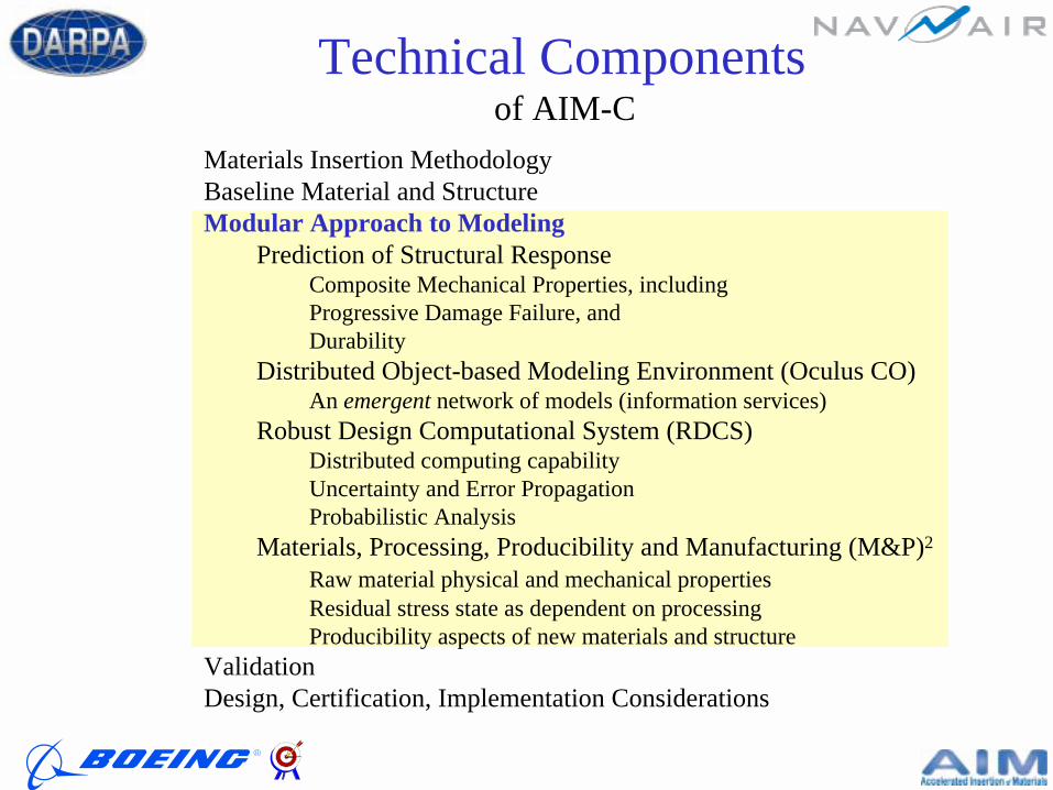
Technical Componentsof AIM-C
Materials Insertion MethodologyBaseline Material and StructureModular Approach to Modeling
Prediction of Structural Response Composite Mechanical Properties, includingProgressive Damage Failure, andDurability
Distributed Object-based Modeling Environment (Oculus CO)An emergent network of models (information services)
Robust Design Computational System (RDCS)Distributed computing capability Uncertainty and Error PropagationProbabilistic Analysis
Materials, Processing, Producibility and Manufacturing (M&P)2
Raw material physical and mechanical propertiesResidual stress state as dependent on processingProducibility aspects of new materials and structure
ValidationDesign, Certification, Implementation Considerations
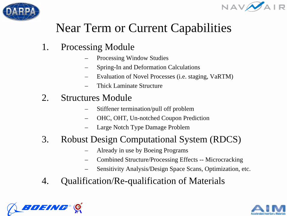
Near Term or Current Capabilities1. Processing Module
– Processing Window Studies– Spring-In and Deformation Calculations – Evaluation of Novel Processes (i.e. staging, VaRTM)– Thick Laminate Structure
2. Structures Module– Stiffener termination/pull off problem– OHC, OHT, Un-notched Coupon Prediction– Large Notch Type Damage Problem
3. Robust Design Computational System (RDCS)– Already in use by Boeing Programs– Combined Structure/Processing Effects -- Microcracking– Sensitivity Analysis/Design Space Scans, Optimization, etc.
4. Qualification/Re-qualification of Materials

Sample Problem 1
Epoxy Cure Hardening Behavior
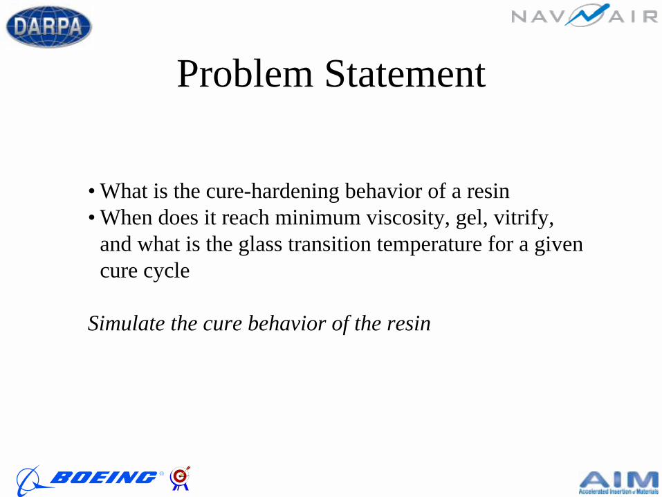
Problem Statement
• What is the cure-hardening behavior of a resin• When does it reach minimum viscosity, gel, vitrify,
and what is the glass transition temperature for a given cure cycle
Simulate the cure behavior of the resin
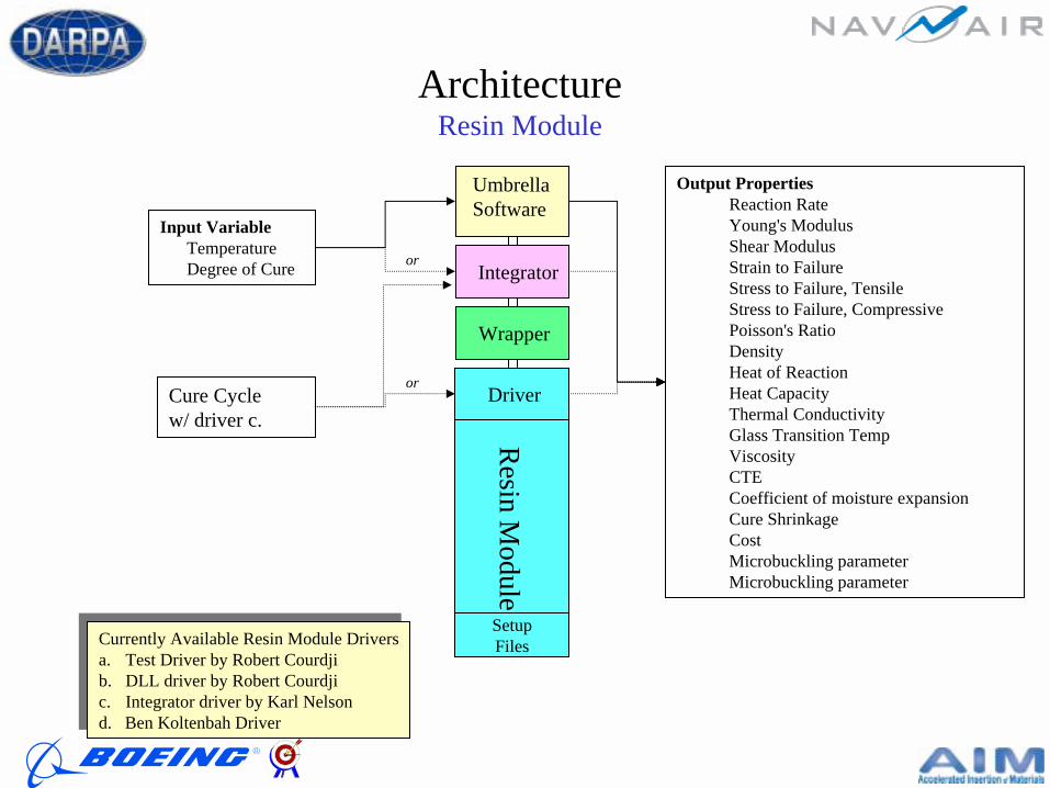
ArchitectureResin Module
Currently Available Resin Module Driversa. Test Driver by Robert Courdjib. DLL driver by Robert Courdjic. Integrator driver by Karl Nelsond. Ben Koltenbah Driver
Currently Available Resin Module Driversa. Test Driver by Robert Courdjib. DLL driver by Robert Courdjic. Integrator driver by Karl Nelsond. Ben Koltenbah Driver
Cure Cyclew/ driver c.
Umbrella Software
Wrapper
Integrator
Resin M
odule
Driver
SetupFiles
or
or
Input VariableTemperatureDegree of Cure
Output PropertiesReaction RateYoung's ModulusShear ModulusStrain to FailureStress to Failure, TensileStress to Failure, CompressivePoisson's RatioDensityHeat of ReactionHeat CapacityThermal ConductivityGlass Transition TempViscosityCTECoefficient of moisture expansionCure ShrinkageCostMicrobuckling parameterMicrobuckling parameter
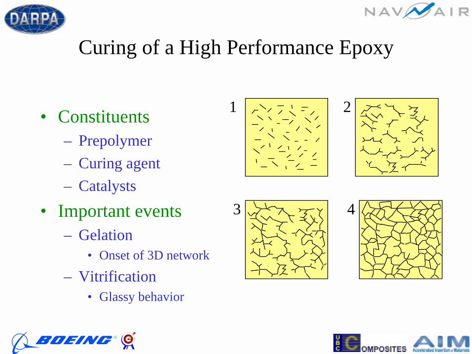
Curing of a High Performance Epoxy
• Constituents– Prepolymer– Curing agent– Catalysts
• Important events– Gelation
• Onset of 3D network
– Vitrification• Glassy behavior
1 2
3 4

Vitrification• Tg = Tg (α)• T < Tg (α) => large reduction of resin free volume
Tg0
Tgf
ααgel0 1
high mobility
low mobility
Tgi
decomposition
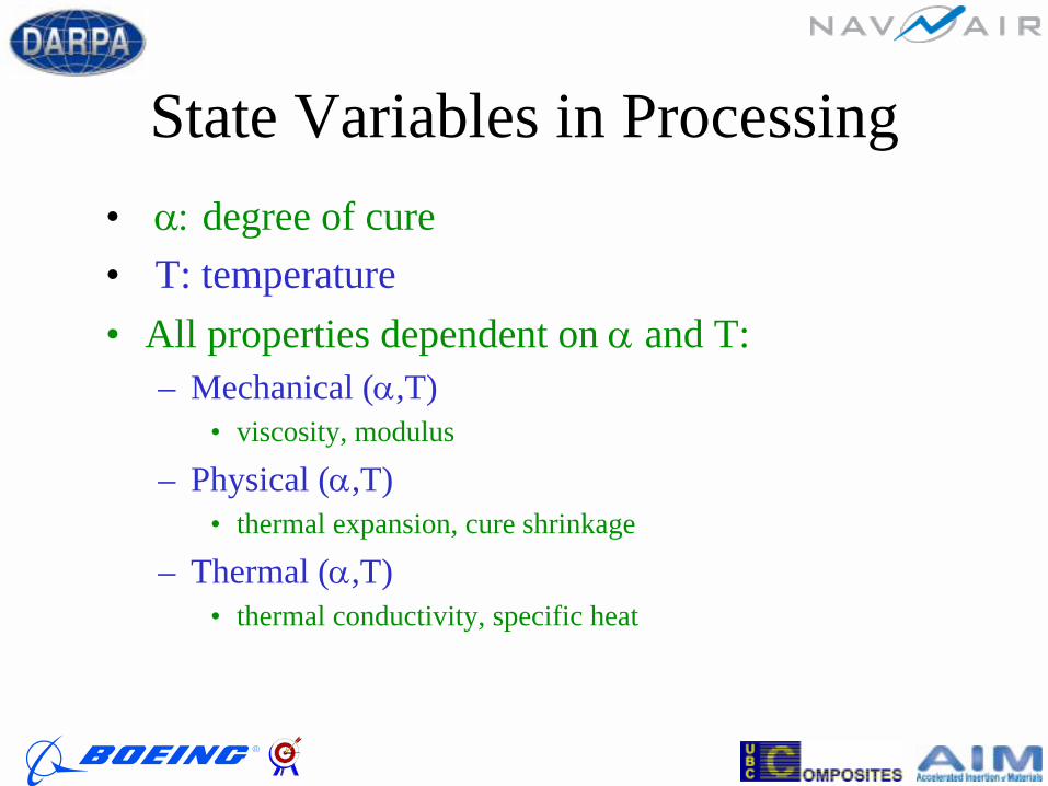
State Variables in Processing• α: degree of cure• T: temperature• All properties dependent on α and T:
– Mechanical (α,T)• viscosity, modulus
– Physical (α,T)• thermal expansion, cure shrinkage
– Thermal (α,T)• thermal conductivity, specific heat
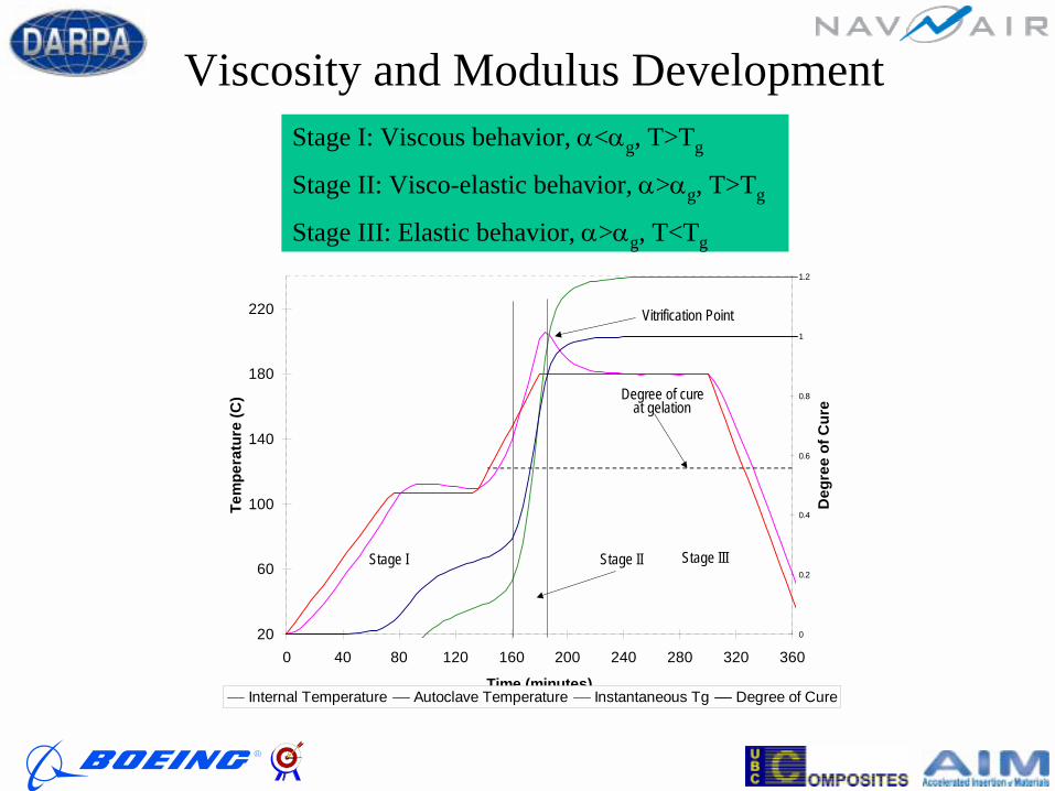
Viscosity and Modulus Development
20
60
100
140
180
220
0 40 80 120 160 200 240 280 320 360
Time (minutes)
Tem
pera
ture
(C)
0
0.2
0.4
0.6
0.8
1
1.2
Deg
ree
of C
ure
Internal Temperature Autoclave Temperature Instantaneous Tg Degree of Cure
Degree of cureat gelation
Vitrification Point
Stage I Stage II Stage III
Stage I: Viscous behavior, α<αg, T>Tg
Stage II: Visco-elastic behavior, α>αg, T>Tg
Stage III: Elastic behavior, α>αg, T<Tg
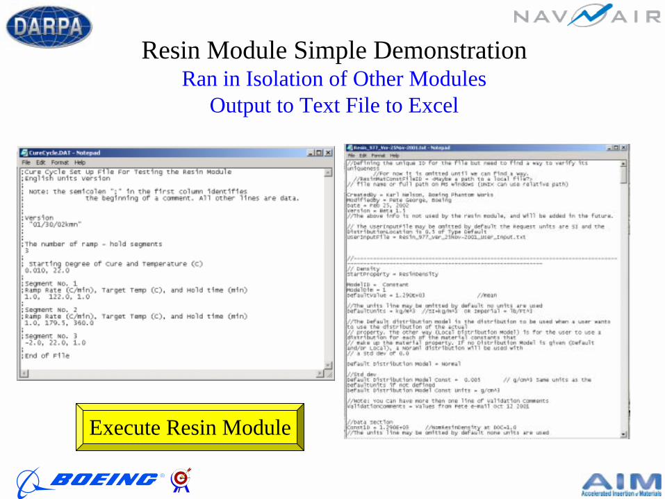
Resin Module Simple DemonstrationRan in Isolation of Other Modules
Output to Text File to Excel
Execute Resin Module

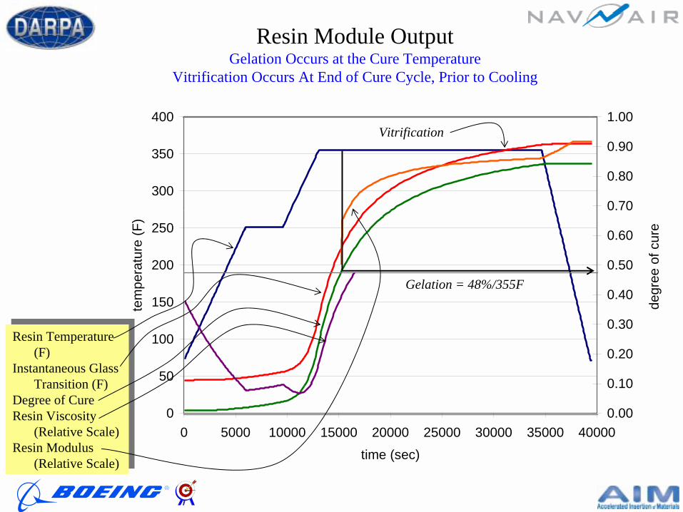
Resin Module Output
0
20
40
60
80
100
120
140
160
180
200
0 10000 20000 30000 40000 50000
Time (sec)
Tem
p (C
)
0.00
0.10
0.20
0.30
0.40
0.50
0.60
0.70
0.80
0.90
Deg
ree
of C
ure
TempDOC
0
50
100
150
200
250
300
350
400
0 5000 10000 15000 20000 25000 30000 35000 40000
time (sec)
tem
pera
ture
(F)
0.00
0.10
0.20
0.30
0.40
0.50
0.60
0.70
0.80
0.90
1.00
degr
ee o
f cur
e
Gelation = 48%/355F
Resin Module OutputGelation Occurs at the Cure Temperature
Vitrification Occurs At End of Cure Cycle, Prior to Cooling
Vitrification
Resin Temperature (F)
Instantaneous Glass Transition (F)
Degree of CureResin Viscosity
(Relative Scale)Resin Modulus
(Relative Scale)
Resin Temperature (F)
Instantaneous Glass Transition (F)
Degree of CureResin Viscosity
(Relative Scale)Resin Modulus
(Relative Scale)

Logic Relay
PowerSupply
Heating ChambeFixed Support
Fiber
ThermocoupleHeater
Linear StagesLoad Cell Resin
nputInput
Computer
Output
Motion Controller
Schematic of CIST Apparatus(cure-induced stress test)
University of Tennessee, Madu Madukar
1.00E-01
1.00E+00
1.00E+01
1.00E+02
1.00E+03
1.00E+04
1.00E+05
0 1 2 3 4 5 6 7 8
Time (hrs)
Visc
osity
(Pa.
sec)
0
20
40
60
80
100
120
140
160
180
200
Tem
pera
ture
(C)
1.0000E+04
1.0000E+05
1.0000E+06
1.0000E+07
1.0000E+08
1.0000E+09
1.0000E+10
0 1 2 3 4 5 6 7 8
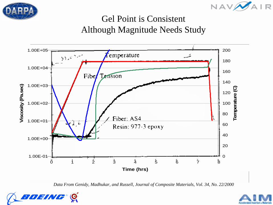
Data From Genidy, Madhukar, and Russell, Journal of Composite Materials, Vol. 34, No. 22/2000
Gel Point is ConsistentAlthough Magnitude Needs Study
-2%
0%
2%
4%
6%
8%
10%
12%
0 1 2 3 4 5 6 7 8 9
Time (hrs)
Volu
me
Cha
nge
(%)
0
50
100
150
200
Tem
pera
ture
(C)
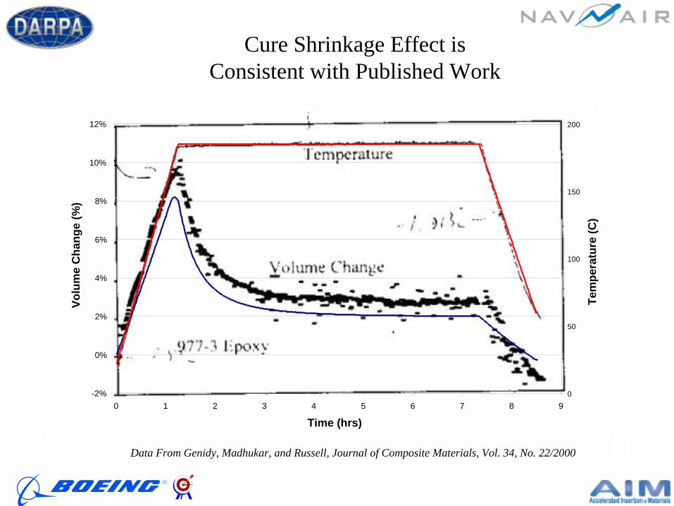
Data From Genidy, Madhukar, and Russell, Journal of Composite Materials, Vol. 34, No. 22/2000
Cure Shrinkage Effect is Consistent with Published Work

Sample Problem 2
Zero CTE Structure
Problem Statement
• Zero CTE composites are often used in applications needing thermally stable structure.
• A zero CTE laminate is produced by using low or negative CTE carbon fiber laminates.
Determine a layup (fiber angle stacking sequence) that would give you a zero CTE laminate.
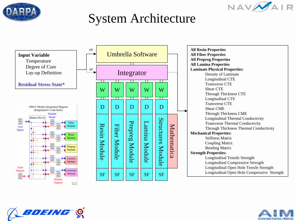
System Architecture
or
orInput Variable
TemperatureDegree of CureLay-up Definition
Residual Stress State*
Umbrella Software
W
Resin M
odule
D
SF
W
Fiber Module
D
SF
W
Prepreg Module
D
SF
W
Lamina M
odule
D
SF
W
Structures Module
D
SF
Integrator
All Resin PropertiesAll Fiber PropertiesAll Prepreg PropertiesAll Lamina PropertiesLaminate Physical Properties:
Density of Laminate Longitudinal CTETransverse CTEShear CTEThrough Thickness CTELongitudinal CTETransverse CTEShear CMEThrough Thickness CMELongitudinal Thermal ConductivityTransverse Thermal ConductivityThrough Thickness Thermal Conductivity
Mechanical Properties:Stiffness MatrixCoupling MatrixBending Matrix
Strength Properties:Longitudinal Tensile StrengthLongitudinal Compressive StrengthLongitudinal Open Hole Tensile StrengthLongitudinal Open Hole Compressive Strength
Mathem
atica
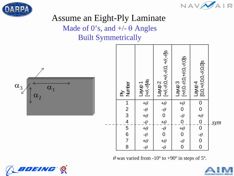
Ply
Num
ber
Layu
p 1
[+θ,
- θ]4
s
Layu
p 2
[+θ,
- θ,0
,+θ,
- θ,0
, +θ,
- θ]s
Layu
p 3
[+θ,
0,- θ
,0,+
θ,0,
- θ,0
]s
Layu
p 4
[0,0
,+θ,
0,0,
- θ,0
,0]s
1 +θ +θ +θ 0 2 -θ -θ 0 0 3 +θ 0 -θ +θ 4 -θ +θ 0 0 5 +θ -θ +θ 0 6 -θ 0 0 -θ 7 +θ +θ -θ 0 8 -θ -θ 0 0
Assume an Eight-Ply Laminate Made of 0’s, and +/- θ Angles
Built Symmetrically
α1α2
α3
sym
θ was varied from -10º to +90º in steps of 5º.
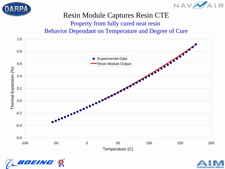
-0.6
-0.4
-0.2
0.0
0.2
0.4
0.6
0.8
1.0
-100 -50 0 50 100 150 200
Temperature (C)
Ther
mal
Exp
ansi
on (%
)
Experimental DataResin Module Output
Resin Module Captures Resin CTEProperty from fully cured neat resin
Behavior Dependant on Temperature and Degree of Cure
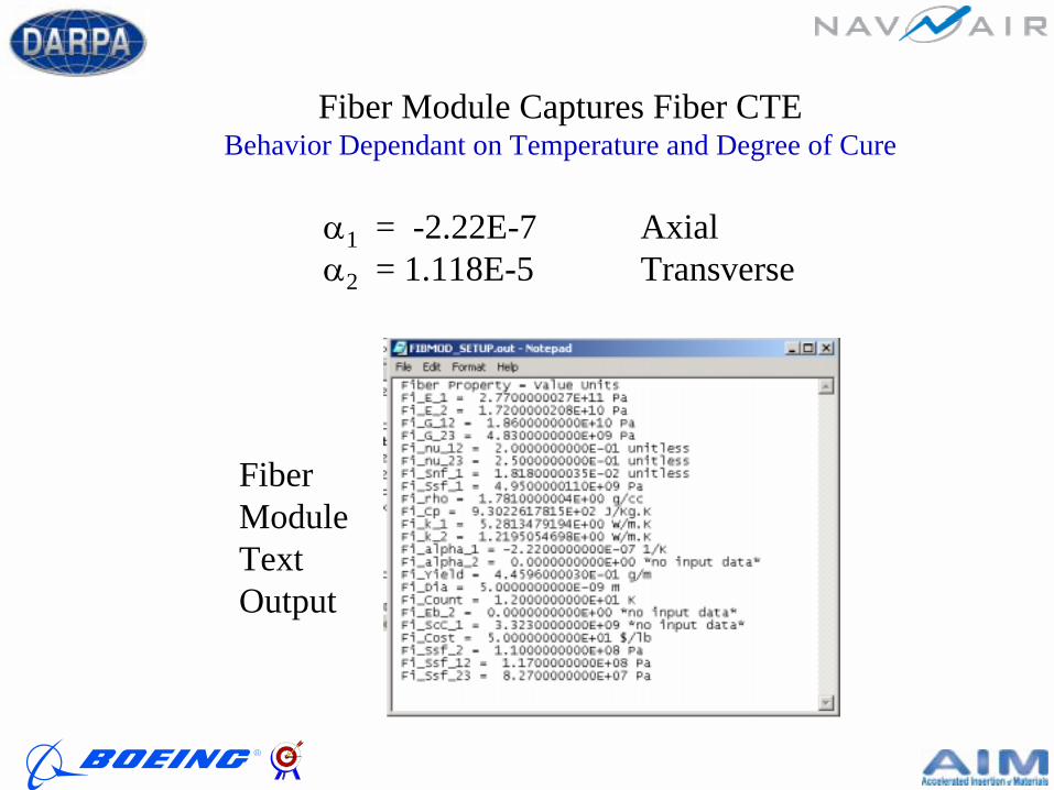
Fiber Module Captures Fiber CTEBehavior Dependant on Temperature and Degree of Cure
α1 = -2.22E-7 Axialα2 = 1.118E-5 Transverse
Fiber Module Text Output
Models for Effective Continuum Properties
Classical Lamination Theory (CLT)
Models for Effective Continuum Properties
Classical Lamination Theory (CLT)
Models forContinuous Fiber Composites
Composite Cylinders Assemblage (CCA)Generalized Self-Consistent Method (GSCM)
Models forContinuous Fiber Composites
Composite Cylinders Assemblage (CCA)Generalized Self-Consistent Method (GSCM)
Models for Predicting Structural Response Level 1 : Parametric Analyses; elastic laminate with approximations
Models for Predicting Structural Response Level 1 : Parametric Analyses; elastic laminate with approximations
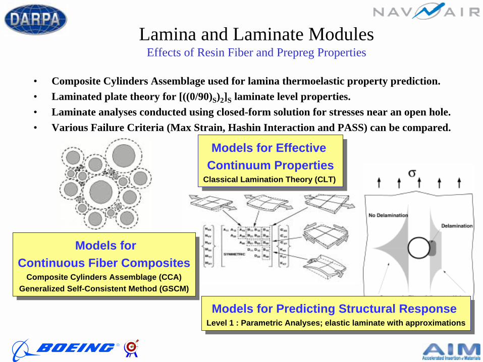
• Composite Cylinders Assemblage used for lamina thermoelastic property prediction.• Laminated plate theory for [((0/90)S)2]S laminate level properties.• Laminate analyses conducted using closed-form solution for stresses near an open hole.• Various Failure Criteria (Max Strain, Hashin Interaction and PASS) can be compared.
Lamina and Laminate ModulesEffects of Resin Fiber and Prepreg Properties

Results of AnalysisTwo Solutions, at ~0-deg, and ~43-deg
The difference in solutions is due to resin and fiber typeLayup 4 with θ = 49-deg gives a “robust” solution
(b) ref. Principe, F. S., Manib, M.M., and Linsenmann, D. R., Design Requirements, pp 181 – 184, in Engineered Materials Handbook, Volume 1, 1987 Composites, ASM International.
Sample Problem 3
Cure of Thick LaminatesCure Cycle Development
Problem Statement
• The heat of reaction during cure can create extremely high temperatures, especially in thick laminates.
• Autoclaves heat transfer characteristics vary greatly, compounding the problem.
Develop a robust cure cycle for a thick laminate, given inherent variability due to heat transfer.
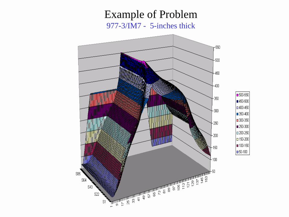
Example of Problem977-3/IM7 - 5-inches thick
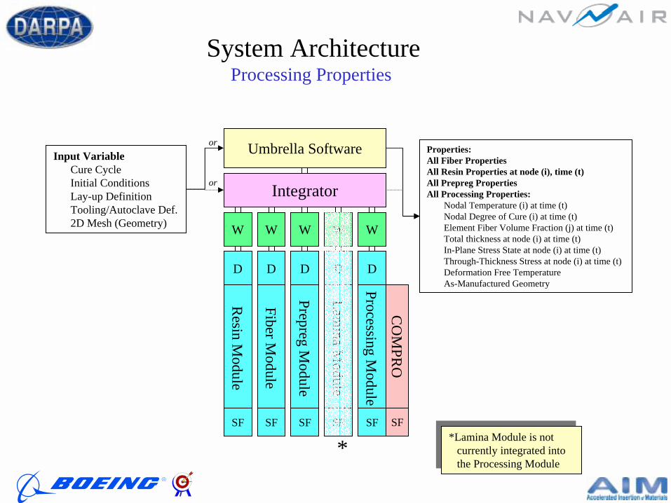
System ArchitectureProcessing Properties
CO
MPR
O
Umbrella Software
W
Resin M
odule
D
SF
W
Fiber Module
D
SF
W
Prepreg Module
D
SF
W
Lamina M
odule
D
SF
W
Processing Module
D
SF
Integrator
SF
or
orInput Variable
Cure CycleInitial ConditionsLay-up DefinitionTooling/Autoclave Def.2D Mesh (Geometry)
Properties:All Fiber PropertiesAll Resin Properties at node (i), time (t)All Prepreg PropertiesAll Processing Properties:
Nodal Temperature (i) at time (t)Nodal Degree of Cure (i) at time (t)Element Fiber Volume Fraction (j) at time (t)Total thickness at node (i) at time (t)In-Plane Stress State at node (i) at time (t)Through-Thickness Stress at node (i) at time (t)Deformation Free TemperatureAs-Manufactured Geometry
*Lamina Module is not currently integrated into the Processing Module
*Lamina Module is not currently integrated into the Processing Module
*
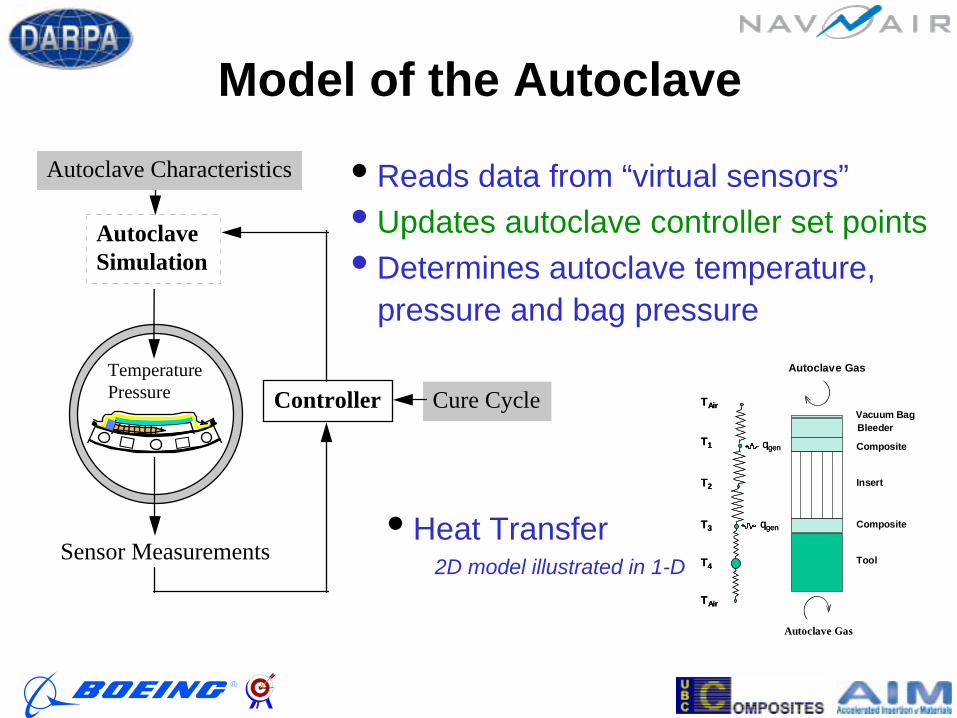
Model of the Autoclave
• Reads data from “virtual sensors”• Updates autoclave controller set points• Determines autoclave temperature,
pressure and bag pressure
Sensor Measurements
Cure CycleTemperaturePressure
Autoclave Characteristics
Controller
AutoclaveSimulation
Tool
Composite
Insert
Composite
BleederVacuum Bag
Autoclave Gas
TAir
T4
T3
T2
T1
TAir
TAir
T4
T3
T2
T1
TAir
qgen
qgen
qgen
qgen
Autoclave Gas
• Heat Transfer 2D model illustrated in 1-D

AIM Processing Module
Convection Boundaries
5” thick part on 0.5” thick Invar tool
Adiabatic Boundary
Convection Boundary
• Look at part temperature with respect to time and position along center line
Top Caul Sheet

Heat Transfer Variability
Variation in Heat Transfer Coefficient
y = 1.830E-04x + 3.740E+01
y = 3.160E-05x + 1.260E+01
y = 4.553E-05x + 1.678E+01
y = 2.478E-05x + 1.917E+01 Bagged
y = 1.073E-04x + 2.500E+01
0.0
20.0
40.0
60.0
80.0
100.0
120.0
140.0
160.0
- 100,000 200,000 300,000 400,000 500,000 600,000 700,000
Pressure (Pa)
Hea
t Tra
nsfe
r Coe
ffici
ent (
W/m
^2.K
)
Relationships from JohnstonBased on Various Boeing/UBC Autoclaves
Relationships by Nelsonbased on BMT North Autoclave
Median Value

Process Specification
Base-Line 4.25 deg F/min
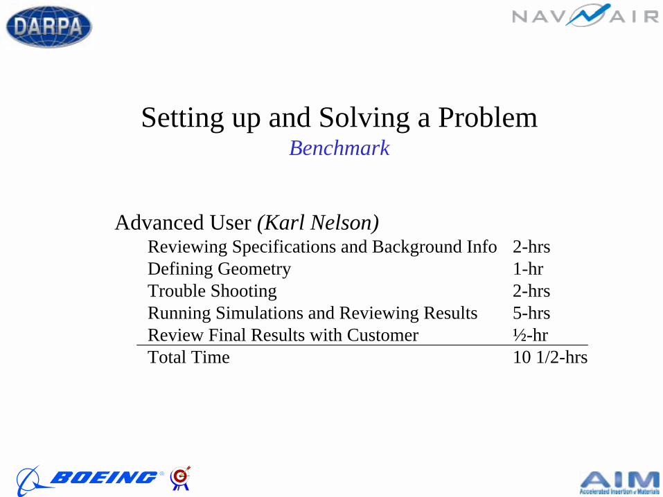
Setting up and Solving a ProblemBenchmark
Advanced User (Karl Nelson)Reviewing Specifications and Background Info 2-hrsDefining Geometry 1-hrTrouble Shooting 2-hrsRunning Simulations and Reviewing Results 5-hrsReview Final Results with Customer ½-hrTotal Time 10 1/2-hrs
0
50
100
150
200
250
300
350
400
0 50 100 150 200 250 300 350
Time (min)
Tem
pera
ture
(F)
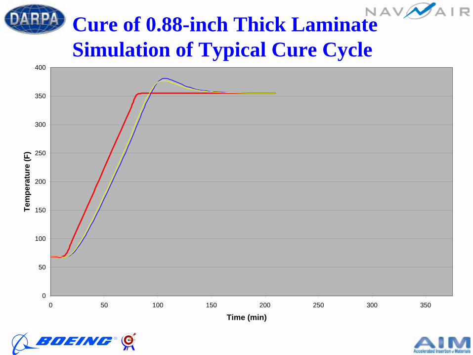
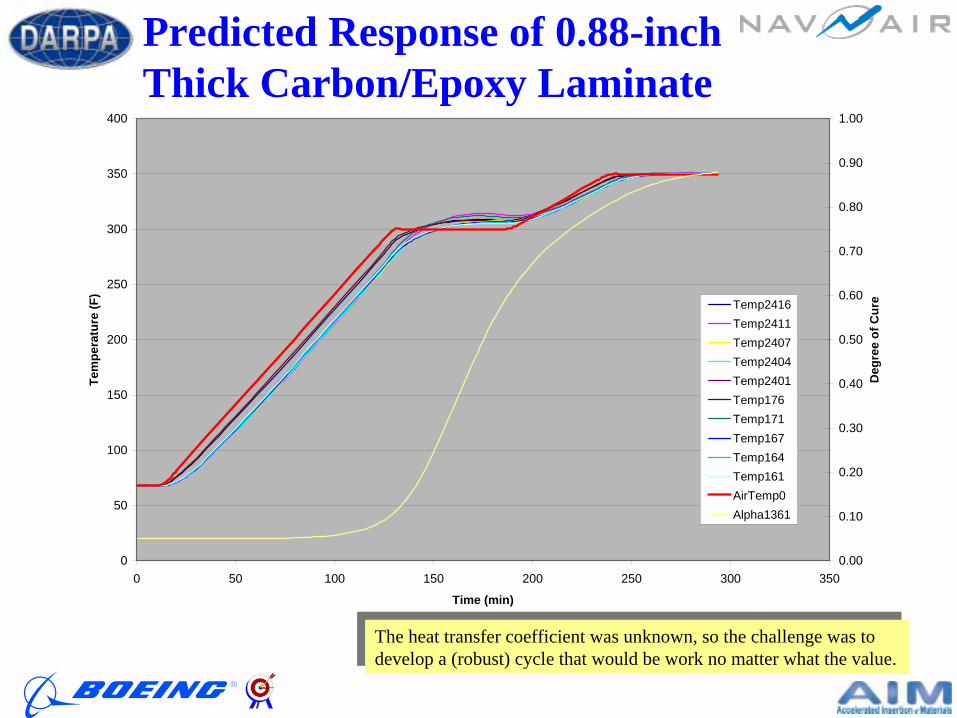
Cure of 0.88-inch Thick LaminateSimulation of Typical Cure Cycle

Engineering RecommendationBased on Processing Module (COMPRO) Results
1. Heat at a maximum heating rate (based on air thermocouple) of 2F/min up to a 300 +/- 10F hold.
2. Hold at 300 +/- 10F for a minimum of 60-minutes.3. Heat at a maximum heating rate of 1F/min to a target of
350F (350+15/-5)4. Hold base on the lagging part thermocouple for 120-min (as
prescribed in processing specification). 5. Complete the cycle as put forth in processing specification.
0
50
100
150
200
250
300
350
400
0 50 100 150 200 250 300 350
Time (min)
Tem
pera
ture
(F)
0.00
0.10
0.20
0.30
0.40
0.50
0.60
0.70
0.80
0.90
1.00
Deg
ree
of C
ureTemp2416
Temp2411Temp2407Temp2404Temp2401Temp176Temp171Temp167Temp164Temp161AirTemp0Alpha1361
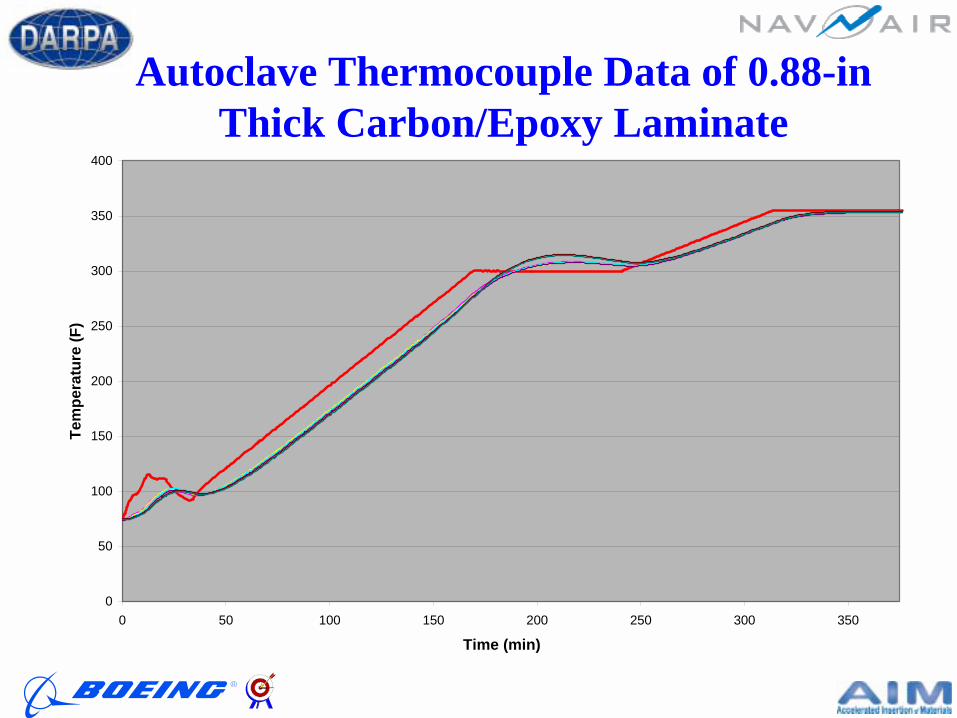
The heat transfer coefficient was unknown, so the challenge was to develop a (robust) cycle that would be work no matter what the value.The heat transfer coefficient was unknown, so the challenge was to develop a (robust) cycle that would be work no matter what the value.
Predicted Response of 0.88-inch Thick Carbon/Epoxy Laminate
0
50
100
150
200
250
300
350
400
0 50 100 150 200 250 300 350
Time (min)
Tem
pera
ture
(F)
Autoclave Thermocouple Data of 0.88-inThick Carbon/Epoxy Laminate

Problem Solution of John Kooch Can We Cure a Laminate up to 5-inches?
• Process design by analysis – validate by test• Carbon/Epoxy• Current simulations indicate yes• Test run just completed at Boeing MR&D in
Auburn– 3.5-inch thick laminate 18-inch square.

Successful Cure of 3 ½ inch Thick Laminate
First Time - Using Analysis To Specify Cure Cycle
0
50
100
150
200
250
300
350
400
0 50 100 150 200 250 300 350 400 450 500 550 600 650 700 750 800
Tem
pera
ture
, deg
F
0
50
100
150
200
250
300
350
400
0 50 100 150 200 250 300 350 400 450 500 550 600 650 700 750 800 850 900
Time, minutes
Tem
pera
ture
, deg
F
AnalyzedAnalyzed
MeasuredMeasured
More Complex Problems
• How do you use the tools to design and build a complex composite structure?
• Can you accurately predict failure and the failure mode:
Demonstrate capability with the design of a hat-stiffened panel -- Currently being worked as our part of our validation/demonstration

ArchitectureStrength Properties
Residual Stress State from Processing Module
User InputCure CycleMaterial System (Implied)Lay-up DefinitionTooling/Autoclave Def.2D Mesh (Processing)3D Mesh (Structures)
Umbrella Software
W
Architect N
o. 5M
odules and Wrappers
D
SF
W
Architect N
o. 6M
odules and Wrappers
D
SF
Integratoror
or
PropertiesAll Fiber PropertiesAll Resin PropertiesAll Prepreg PropertiesAll Lamina PropertiesAll Processing PropertiesAll Structures Properties
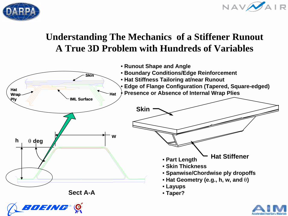
Skin
Hat Stiffener
Sect A-A
hw
θ deg
• Part Length• Skin Thickness• Spanwise/Chordwise ply dropoffs • Hat Geometry (e.g., h, w, and θ)• Layups• Taper?
Understanding The Mechanics of a Stiffener RunoutA True 3D Problem with Hundreds of Variables
IML SurfaceHat
HatWrapPly
Skin
IML SurfaceHat
HatWrapPly
Skin
• Runout Shape and Angle• Boundary Conditions/Edge Reinforcement• Hat Stiffness Tailoring at/near Runout• Edge of Flange Configuration (Tapered, Square-edged)• Presence or Absence of Internal Wrap Plies

Comments and Summary• Accelerated Insertion of Materials Can be
Achieved by– Definition of requirements– Focus based on insertion needs (DKB)– Approach for use of existing Knowledge– Validated Analysis tools– Focused Testing– Feature Based Demonstration– Rework Avoidance– Knowledge management
The Objective of the AIM-C Program is to Provide Concepts, an Approach, and Tools That Can Accelerate the Insertion of Composite Materials
Into DoD Products
AIM-C Will Accomplish This Three Ways
Methodology - We will evaluate the historical roadblocks to effective implementation of composites and offer a process or protocol to eliminate these roadblocks and a strategy to expand the use of the systems and processes developed.
Product Development - We will develop a software tool, resident and accessible throughthe Internet that will allow rapid evaluation of composite materials for various applications.
Demonstration/Validation - We will provide a mechanism for acceptance by primary users of the system and validation by those responsible for certification of the applications in which the new materials may be used.
AIM-C Alignment Tool