ac motor systems us series - orientalmotor.com · us series rohs-compliant the us series is a panel...
TRANSCRIPT

B-202 ORIENTAL MOTOR GENERAL CATALOG 2009/2010 Features B-202 / System Configuration B-203 / Product Line B-204 / Specifications B-205
Sp
eed
Co
ntro
l Syste
ms
●Additional Information●Technical reference ➜ Page F-1
Safety standards ➜ Page G-2
AC Motor Systems
US Series
RoHS-Compliant
The US Series is a panel mounted control unit and
speed control motor package, which conforms to the
RoHS Directive. Wiring is performed by connecting
with easy-to-use connectors. This series is optimal for
easy speed control applications.
Instantaneous stop function is not equipped. ●
List of safety standard approved products (Model, Standards, File No., Certification Body) ●➜ Page G-11
(Gearhead sold separately)
Features ■
Easy Connection ●The operation is possible just by connecting the control unit into the
power supply after connecting the motor and control unit through
easy-to-use connectors.
Easy Operation ●The speed can be set easily with the potentiometer on the front
panel of the control unit.
● RoHS-CompliantThe US Series conforms to the RoHS Directive that prohibits the use
of six chemical substances including lead and cadmium.
Details of RoHS Directive ● ➜ Page G-38
Approved by Major Safety Standards ●The US Series is recognized by UL and CSA, and certified under the
China Compulsory Certification System (CCC System). CE Marking
is used in accordance with the Low Voltage Directive and EMC
Directive.
Protective Earth Terminal on Motor ●[6 W (1/125 HP) to 40 W (1/19 HP)]
Variable Speed Range ●50 Hz: 90 to 1400 r/min
60 Hz: 90 to 1600 r/min
Types and Features of Gearhead ■
Long Life, Low Noise ● GN-S Gearhead is Available. [Applicable motors: 6 W (1/125 HP) to 40 W (1/19 HP)]
The "long life, low noise GN-S gearhead" achieves
a long rated life of 10000 hours, twice the level of
a conventional gearhead, by adopting innovative
technologies and structure. Also, the gearhead is
low noise designed.
Details of long life, low noise ● GN-S gearhead ➜ Page B-11
Types of Gearheads ● Gearhead Applicable Motor Rated Life
(hours)Low Noise
Type of Gearhead Type of Pinion Output Power Type of Pinion
Parallel Shaft
Long Life, Low NoiseGN-S Gearhead
GN TypePinion Shaft
6 W∼40 W(1/125 HP∼1/19 HP)
GN TypePinion Shaft
10000 ●
GU GearheadGU Type
Pinion Shaft60 W, 90 W
(1/12 HP, 1/8 HP)GU Type
Pinion Shaft5000
Right-AngleShaft
Hollow Shaft Gearhead
GN TypePinion Shaft
25 W, 40 W(1/30 HP, 1/19 HP)
GN TypePinion Shaft
5000
GU TypePinion Shaft
60 W, 90 W(1/12 HP, 1/8 HP)
GU TypePinion Shaft
5000
Solid Shaft Gearhead
GN TypePinion Shaft
25 W, 40 W(1/30 HP, 1/19 HP)
GN TypePinion Shaft
5000
GU TypePinion Shaft
60 W, 90 W(1/12 HP, 1/8 HP)
GU TypePinion Shaft
5000

Sp
eed
Co
ntro
l Syste
ms
Intro
du
ctio
nA
C In
pu
tBX
AC
Inp
ut
BLF
AC
Inp
ut
BLU
AC
Inp
ut
FBL
DC
Inp
ut
BLH
BH
FFE1
00/
FE200
ES01/
ES02
US
Insta
llatio
n
Bru
sh
less M
oto
r Syste
ms
AC
Mo
tor S
yste
ms
B-203Characteristics B-209 / Dimensions B-210 / Connection and Operation B-216 / Motor and Control Unit Combinations B-217
System Configuration ■
US Series
Gearhead (Sold separately)
Accessories (Sold separately)
●Example of System Configuration(Sold separately)(Sold separately)
Motor(Pinion Shaft)
Control Unit
AC Power Supply(Main power supply)
③Mounting Brackets(➜ Page A-288)
②Motor Speed Indicator●Not a standard certified product (➜ Page A-298)
①Extension Cables(➜ Page B-218)
④Flexible Couplings(➜ Page A-292)
Long Life, Low Noise Gearhead
4GN25SA
US Series(Pinion shaft)
US425-401U2
Parallel Shaft Gearheads (➜ Page B-11)
Hollow Shaft Type Solid Shaft Type
Right-Angle Gearheads (➜ Page A-239)
●Gearheads cannot be combined with round shaft type motors.
No. Product Name Overview PageB-218A-298A-288
①
②
Extension CablesMotor Speed Indicator
Cable for extending the wiring distance between the motor and control unit [1 to 4 m (3.3 to 13.1 ft.)].Indicates motor speed of the speed control motor (SDM496).
A-292③
④
Mounting BracketsFlexible Couplings
Dedicated mounting bracket for the motor and gearhead.Clamp type coupling that connects the motor or gearhead shaft to the driven shaft.
Capacitor Cap(Included)✽
Capacitor (Included)✽
Extension Cable[1 m (3.3 ft.)]
FlexibleCoupling
CC01SU05 MCL30F06F06SOL4U10
MountingBracket
SDM496
Motor SpeedIndicator
✽ Included with the 60 W (1/12 HP) and 90 W (1/8 HP) types.
The system configuration shown above is an example. Other combinations are available. ●
B-204 ORIENTAL MOTOR GENERAL CATALOG 2009/2010 Features B-202 / System Configuration B-203 / Product Line B-204 / Specifications B-205
Sp
eed
Co
ntro
l Syste
ms
Product Number Code ■
US ● Series
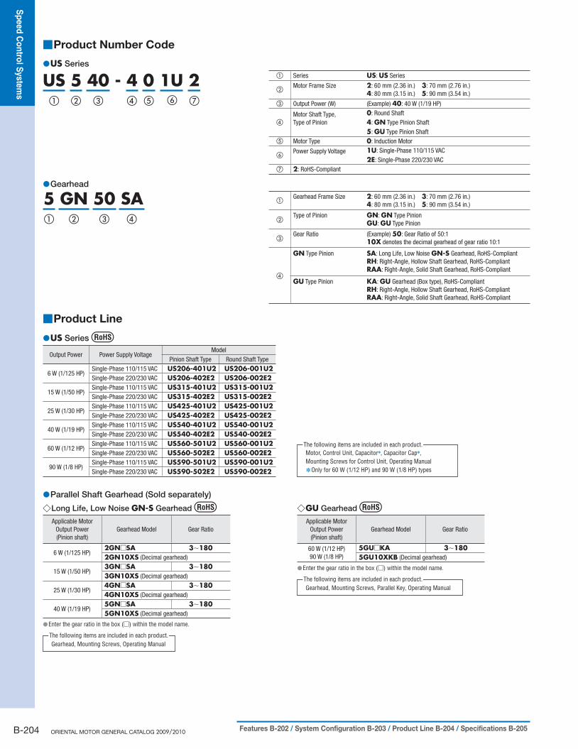
US 5 40 - 4 0 1U 2① ② ③ ⑥④ ⑤ ⑦
① Series US: US Series
②Motor Frame Size 2: 60 mm (2.36 in.) 3: 70 mm (2.76 in.)
4: 80 mm (3.15 in.) 5: 90 mm (3.54 in.)
③ Output Power (W) (Example) 40: 40 W (1/19 HP)
④Motor Shaft Type, Type of Pinion
0: Round Shaft4: GN Type Pinion Shaft5: GU Type Pinion Shaft
⑤ Motor Type 0: Induction Motor
⑥Power Supply Voltage 1U: Single-Phase 110/115 VAC
2E: Single-Phase 220/230 VAC⑦ 2: RoHS-Compliant
Gearhead ●
5 GN 50 SA① ② ③ ④
①Gearhead Frame Size 2: 60 mm (2.36 in.) 3: 70 mm (2.76 in.)
4: 80 mm (3.15 in.) 5: 90 mm (3.54 in.)
②Type of Pinion GN: GN Type Pinion
GU: GU Type Pinion
③Gear Ratio (Example) 50: Gear Ratio of 50:1
10X denotes the decimal gearhead of gear ratio 10:1
④
GN Type Pinion SA: Long Life, Low Noise GN-S Gearhead, RoHS-CompliantRH: Right-Angle, Hollow Shaft Gearhead, RoHS-CompliantRAA: Right-Angle, Solid Shaft Gearhead, RoHS-Compliant
GU Type Pinion KA: GU Gearhead (Box type), RoHS-CompliantRH: Right-Angle, Hollow Shaft Gearhead, RoHS-CompliantRAA: Right-Angle, Solid Shaft Gearhead, RoHS-Compliant
Product Line ■
US ● Series
Output Power Power Supply VoltageModel
Pinion Shaft Type Round Shaft Type
6 W (1/125 HP)Single-Phase 110/115 VAC US206-401U2 US206-001U2Single-Phase 220/230 VAC US206-402E2 US206-002E2
15 W (1/50 HP)Single-Phase 110/115 VAC US315-401U2 US315-001U2Single-Phase 220/230 VAC US315-402E2 US315-002E2
25 W (1/30 HP)Single-Phase 110/115 VAC US425-401U2 US425-001U2Single-Phase 220/230 VAC US425-402E2 US425-002E2
40 W (1/19 HP)Single-Phase 110/115 VAC US540-401U2 US540-001U2Single-Phase 220/230 VAC US540-402E2 US540-002E2
60 W (1/12 HP)Single-Phase 110/115 VAC US560-501U2 US560-001U2Single-Phase 220/230 VAC US560-502E2 US560-002E2
90 W (1/8 HP)Single-Phase 110/115 VAC US590-501U2 US590-001U2Single-Phase 220/230 VAC US590-502E2 US590-002E2
Motor, Control Unit, Capacitor✽, Capacitor Cap✽, Mounting Screws for Control Unit, Operating Manual
Only for 60 W (1/12 HP) and 90 W (1/8 HP) types ✽
The following items are included in each product.
Parallel Shaft Gearhead (Sold separately) ●Long Life, Low Noise ◇ GN-S Gearhead
Applicable Motor Output Power(Pinion shaft)
Gearhead Model Gear Ratio
6 W (1/125 HP)2GN□SA 3∼1802GN10XS (Decimal gearhead)
15 W (1/50 HP)3GN□SA 3∼1803GN10XS (Decimal gearhead)
25 W (1/30 HP)4GN□SA 3∼1804GN10XS (Decimal gearhead)
40 W (1/19 HP)5GN□SA 3∼1805GN10XS (Decimal gearhead)
Enter the gear ratio in the box ( ● □) within the model name.
Gearhead, Mounting Screws, Operating ManualThe following items are included in each product.
GU ◇ Gearhead
Applicable Motor Output Power(Pinion shaft)
Gearhead Model Gear Ratio
60 W (1/12 HP)90 W (1/8 HP)
5GU□KA 3∼1805GU10XKB (Decimal gearhead)
Enter the gear ratio in the box ( ● □) within the model name.
Gearhead, Mounting Screws, Parallel Key, Operating ManualThe following items are included in each product.

Sp
eed
Co
ntro
l Syste
ms
Intro
du
ctio
nA
C In
pu
tBX
AC
Inp
ut
BLF
AC
Inp
ut
BLU
AC
Inp
ut
FBL
DC
Inp
ut
BLH
BH
FFE1
00/
FE200
ES01/
ES02
US
Insta
llatio
n
Bru
sh
less M
oto
r Syste
ms
AC
Mo
tor S
yste
ms
B-205Characteristics B-209 / Dimensions B-210 / Connection and Operation B-216 / Motor and Control Unit Combinations B-217
Specifications – Continuous Rating ■
ModelMax.
Output Power
Voltage FrequencyVariable Speed Range✽
Permissible TorqueStarting Torque
CurrentPower
Consumption1200r/min
90r/min
Pinion Shaft Type Round Shaft Type W (HP) VAC Hz r/min mN·m (oz-in) mN·m (oz-in) mN·m (oz-in) A W
US206-401U2 US206-001U2 6 (1/125)Single-Phase 110
60 90∼1600 50 (7.1) 37 (5.2) 40 (5.6) 0.28 28Single-Phase 115
US206-402E2 US206-002E2 6 (1/125)Single-Phase 220
50 90∼1400 44 (6.2) 40 (5.6) 38 (5.3)
0.13 2860 90∼1600 50 (7.1) 39 (5.5) 40 (5.6)
Single-Phase 23050 90∼1400 47 (6.6) 38 (5.3)
40 (5.6)60 90∼1600 50 (7.1) 37 (5.2)
US315-401U2 US315-001U2 15 (1/50)Single-Phase 110
60 90∼1600 125 (17.7) 45 (6.3) 55 (7.8)0.47
44Single-Phase 115 0.50
US315-402E2 US315-002E2 15 (1/50)Single-Phase 220
50 90∼1400 125 (17.7)
35 (4.9)
54 (7.6) 0.21 4060 90∼1600 85 (12.0) 52 (7.3) 0.18 39
Single-Phase 23050 90∼1400 125 (17.7) 54 (7.6) 0.21 4160 90∼1600 105 (14.9) 55 (7.8) 0.22 44
US425-401U2 US425-001U2 25 (1/30)Single-Phase 110
60 90∼1600 200 (28) 50 (7.1) 105 (14.9) 0.7470
Single-Phase 115 73
US425-402E2 US425-002E2 25 (1/30)Single-Phase 220
50 90∼1400 205 (29)40 (5.6) 100 (14.2)
0.36
6860 90∼1600 160 (22) 0.37
Single-Phase 23050 90∼1400 205 (29) 40 (5.6)
110 (15.6)0.35
60 90∼1600 140 (19.8) 35 (4.9) 0.36
US540-401U2 US540-001U2 40 (1/19)Single-Phase 110
60 90∼1600 260 (36) 70 (9.9) 180 (25) 1.1102
Single-Phase 115 105
US540-402E2 US540-002E2 40 (1/19)Single-Phase 220
50 90∼1400 300 (42)
63 (8.9)
140 (19.8) 0.53 9060 90∼1600 230 (32) 125 (17.7) 0.55 98
Single-Phase 23050 90∼1400 300 (42) 140 (19.8) 0.53 9060 90∼1600 230 (32) 140 (19.8) 0.55 100
US560-501U2 US560-001U2 60 (1/12)Single-Phase 110
60 90∼1600 490 (69) 200 (28) 285 (40)2.0 178
Single-Phase 115 2.1 186
US560-502E2 US560-002E2 60 (1/12)Single-Phase 220
50 90∼1400 490 (69) 140 (19.8) 240 (34) 0.85 15460 90∼1600 450 (63) 160 (22) 210 (29) 0.86 159
Single-Phase 23050 90∼1400 490 (69) 140 (19.8) 240 (34) 0.89 15460 90∼1600 450 (63) 160 (22) 240 (34) 0.88 165
US590-501U2 US590-001U2 90 (1/8)Single-Phase 110
60 90∼1600 730 (103) 200 (28) 405 (57) 2.6230
Single-Phase 115 246
US590-502E2 US590-002E2 90 (1/8)Single-Phase 220
50 90∼1400
730 (103)
230 (32) 360 (51) 1.1 20060 90∼1600 260 (36) 360 (51)
1.2221
Single-Phase 23050 90∼1400 230 (32) 400 (56) 20160 90∼1600 260 (36) 400 (56) 227
The variable speed ranges shown are under no load conditions. ✽
: Impedance protected: Contains a built-in thermal protector (automatic return type). If a motor overheats for any reason, the thermal protector is activated and the motor is stopped.When the motor temperature drops, the thermal protector closes and the motor restarts. Be sure to turn the motor off before inspecting.
Following gearheads are also available. For details, please refer to website ●(http://www.orientalmotor.com/) or contact the nearest Oriental Motor sales office.
Gearhead Type Gearhead Model Gear Ratio
Parallel Shaft GN-K Gearhead
2GN□KA 3∼1802GN10XK (Decimal gearhead)3GN□KA 3∼1803GN10XK (Decimal gearhead)4GN□KA 3∼1804GN10XK (Decimal gearhead)5GN□KA 3∼1805GN10XK (Decimal gearhead)
Right-Angle Gearhead (Sold separately) ●Hollow Shaft Type ◇
Applicable Motor Output Power(Pinion shaft)
Gearhead Model Gear Ratio
25 W (1/30 HP) 4GN□RH 3∼18040 W (1/19 HP) 5GN□RH 3∼18060 W (1/12 HP)90 W (1/8 HP)
5GU□RH 3∼180
Enter the gear ratio in the box ( ● □) within the model name.
Gearhead, Mounting Screws, Parallel Key, Safety Cover (with screws), Gasket, Operating Manual
The following items are included in each product.
Solid Shaft Type ◇
Applicable Motor Output Power(Pinion shaft)
Gearhead Model Gear Ratio
25 W (1/30 HP) 4GN□RAA 3∼18040 W (1/19 HP) 5GN□RAA 3∼18060 W (1/12 HP)90 W (1/8 HP)
5GU□RAA 3∼180
Enter the gear ratio in the box ( ● □) within the model name.
Gearhead, Mounting Screws, Parallel Key✽, Gasket, Operating ManualOnly for the products with a key slot on the output shaft ✽
The following items are included in each product.
B-206 ORIENTAL MOTOR GENERAL CATALOG 2009/2010 Features B-202 / System Configuration B-203 / Product Line B-204 / Specifications B-205
Sp
eed
Co
ntro
l Syste
ms
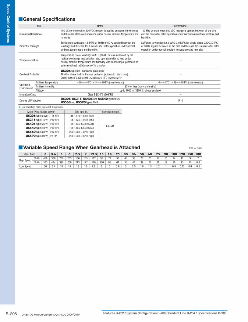
General Specifications ■
Item Motor Control Unit
Insulation Resistance100 MΩ or more when 500 VDC megger is applied between the windings and the case after rated operation under normal ambient temperature and humidity.
100 MΩ or more when 500 VDC megger is applied between all the pins and the case after rated operation under normal ambient temperature and humidity.
Dielectric StrengthSufficient to withstand 1.5 kVAC at 50 Hz or 60 Hz applied between the windings and the case for 1 minute after rated operation under normal ambient temperature and humidity.
Sufficient to withstand 2.3 kVAC (3.0 kVAC for single-phase 220/230 VAC) at 60 Hz applied between all the pins and the case for 1 minute after rated operation under normal ambient temperature and humidity.
Temperature Rise
Temperature rise of windings is 80˚C (144˚F) or less measured by the resistance change method after rated operation with no load under normal ambient temperature and humidity with connecting a gearhead or equivalent heat radiation plate✽ to a motor.
−
Overheat ProtectionUS206 type has impedance protection.All others have built-in thermal protector (automatic return type).Open: 130±5˚C (266±9˚F), Close: 82±15˚C (179.6±27˚F)
−
Operating Environment
Ambient Temperature −10∼+40˚C (+14∼+104˚F) (non-freezing) 0∼+40˚C (+32∼+104˚F) (non-freezing)Ambient Humidity 85% or less (non-condensing)Altitude Up to 1000 m (3300 ft.) above sea level
Insulation Class Class B [130°C (266°F)] −
Degree of ProtectionUS206, US315, US425 and US540 types: IP20US560 and US590 types: IP40
IP10
Heat radiation plate (Material: Aluminum) ✽
Motor Type (Output power) Size mm (in.) Thickness mm (in.)US206 type (6 W) (1/125 HP) 115×115 (4.53×4.53)
5 (0.20)
US315 type (15 W) (1/50 HP) 125×125 (4.92×4.92)US425 type (25 W) (1/30 HP) 135×135 (5.31×5.31)US540 type (40 W) (1/19 HP) 165×165 (6.50×6.50)US560 type (60 W) (1/12 HP) 200×200 (7.87×7.87)US590 type (90 W) (1/8 HP) 200×200 (7.87×7.87)
Variable Speed Range When Gearhead is Attached ■ Unit = r/min
Gear Ratio 3 3.6 5 6 7.5 9 12.5 15 18 25 30 36 50 60 75 90 100 120 150 180
High Speed50 Hz 466 388 280 233 186 155 112 93 77 56 46 38 28 23 18 15 14 11 9 760 Hz 533 444 320 266 213 177 128 106 88 64 53 44 32 26 21 17 16 13 10 8.8
Low Speed 30 25 18 15 12 10 7.2 6 5 3.6 3 2.5 1.8 1.5 1.2 1 0.9 0.75 0.6 0.5

Sp
eed
Co
ntro
l Syste
ms
Intro
du
ctio
nA
C In
pu
tBX
AC
Inp
ut
BLF
AC
Inp
ut
BLU
AC
Inp
ut
FBL
DC
Inp
ut
BLH
BH
FFE1
00/
FE200
ES01/
ES02
US
Insta
llatio
n
Bru
sh
less M
oto
r Syste
ms
AC
Mo
tor S
yste
ms
B-207Characteristics B-209 / Dimensions B-210 / Connection and Operation B-216 / Motor and Control Unit Combinations B-217
Gearmotor – Torque Table ■
Gearheads and decimal gearheads are sold separately. ●Enter the gear ratio in the box ( ● □) within the model name.
A colored background ( ● ) indicates gear shaft rotation in the same direction as the motor shaft, while the others rotate in the opposite
direction.
To reduce the speed beyond the gear ratio in the table, attach a decimal gearhead of gear ratio 10:1 between the gearhead and the motor. ●In that case, the permissible torques are as follows.
2GN□SA: 3 N·m (26 lb-in), 3GN□SA: 5 N·m (44 lb-in)
4GN□SA: 8 N·m (70 lb-in) [6 N·m (53 lb-in) when a gearhead of 25:1 to 36:1 is attached]
5GN□SA: 10 N·m (88 lb-in), 5GU□KA: 20 N·m (177 lb-in)
Single-Phase 110/115 VAC ● Unit = N·m (lb-in)
Model Gear Ratio
3 3.6 5 6 7.5 9 12.5 15 18 25 30 36 50 60 75 90 100 120 150 180Motor/Gearhead
Motor Speedr/min
US206-401U2/2GN□SA
12000.12
(1.06)0.15
(1.32)0.20
(1.77)0.24(2.1)
0.30(2.6)
0.36(3.1)
0.51(4.5)
0.61(5.3)
0.73(6.4)
0.91(8.0)
1.1(9.7)
1.3(11.5)
1.7(15.0)
2.0(17.7)
2.5(22)
3(26)
3(26)
3(26)
3(26)
3(26)
900.090(0.79)
0.11(0.97)
0.15(1.32)
0.18(1.59)
0.22(1.94)
0.27(2.3)
0.37(3.2)
0.45(3.9)
0.54(4.7)
0.68(6.0)
0.81(7.1)
0.97(8.5)
1.2(10.6)
1.5(13.2)
1.8(15.9)
2.2(19.4)
2.4(21)
2.9(25)
3(26)
3(26)
US315-401U2/3GN□SA
12000.30(2.6)
0.36(3.1)
0.51(4.5)
0.61(5.3)
0.76(6.7)
0.91(8.0)
1.3(11.5)
1.5(13.2)
1.8(15.9)
2.3(20)
2.7(23)
3.3(29)
4.1(36)
5(44)
5(44)
5(44)
5(44)
5(44)
5(44)
5(44)
900.11
(0.97)0.13
(1.15)0.18
(1.59)0.22
(1.94)0.27(2.3)
0.33(2.9)
0.46(4.0)
0.55(4.8)
0.66(5.8)
0.82(7.2)
0.99(8.7)
1.2(10.6)
1.5(13.2)
1.8(15.9)
2.2(19.4)
2.7(23)
3.0(26)
3.6(31)
4.5(39)
5(44)
US425-401U2/4GN□SA
12000.49(4.3)
0.58(5.1)
0.81(7.1)
0.97(8.5)
1.2(10.6)
1.5(13.2)
2.0(17.7)
2.4(21)
2.9(25)
3.7(32)
4.4(38)
5.3(46)
6.6(58)
7.9(69)
8(70)
8(70)
8(70)
8(70)
8(70)
8(70)
900.12
(1.06)0.15
(1.32)0.20
(1.77)0.24(2.1)
0.30(2.6)
0.36(3.1)
0.51(4.5)
0.61(5.3)
0.73(6.4)
0.91(8.0)
1.1(9.7)
1.3(11.5)
1.7(15.0)
2.0(17.7)
2.5(22)
3.0(26)
3.3(29)
4.0(35)
5.0(44)
5.9(52)
US540-401U2/5GN□SA
12000.63(5.5)
0.76(6.7)
1.1(9.7)
1.3(11.5)
1.6(14.1)
1.9(16.8)
2.6(23)
3.2(28)
3.8(33)
4.7(41)
5.7(50)
6.8(60)
8.6(76)
10(88)
10(88)
10(88)
10(88)
10(88)
10(88)
10(88)
900.17
(1.50)0.20
(1.77)0.28(2.4)
0.34(3.0)
0.43(3.8)
0.51(4.5)
0.71(6.2)
0.85(7.5)
1.0(8.8)
1.3(11.5)
1.5(13.2)
1.8(15.9)
2.3(20)
2.8(24)
3.5(30)
4.2(37)
4.6(40)
5.5(48)
6.9(61)
8.3(73)
US560-501U2/5GU□KA
12001.2
(10.6)1.4
(12.3)2.0
(17.7)2.4(21)
3.0(26)
3.6(31)
4.5(39)
5.4(47)
6.4(56)
8.1(71)
9.7(85)
11.6(102)
16.2(143)
19.4(171)
20(177)
20(177)
20(177)
20(177)
20(177)
20(177)
900.49(4.3)
0.58(5.1)
0.81(7.1)
0.97(8.5)
1.2(10.6)
1.5(13.2)
1.8(15.9)
2.2(19.4)
2.6(23)
3.3(29)
4.0(35)
4.8(42)
6.6(58)
7.9(69)
8.9(78)
10.6(93)
11.8(104)
14.2(125)
17.7(156)
20(177)
US590-501U2/5GU□KA
12001.8
(15.9)2.1
(18.5)3.0(26)
3.5(30)
4.4(38)
5.3(46)
6.7(59)
8.0(70)
9.6(84)
12.0(106)
14.5(128)
17.3(153)
20(177)
20(177)
20(177)
20(177)
20(177)
20(177)
20(177)
20(177)
900.49(4.3)
0.58(5.1)
0.81(7.1)
0.97(8.5)
1.2(10.6)
1.5(13.2)
1.8(15.9)
2.2(19.4)
2.6(23)
3.3(29)
4.0(35)
4.8(42)
6.6(58)
7.9(69)
8.9(78)
10.6(93)
11.8(104)
14.2(125)
17.7(156)
20(177)
B-208 ORIENTAL MOTOR GENERAL CATALOG 2009/2010 Features B-202 / System Configuration B-203 / Product Line B-204 / Specifications B-205
Sp
eed
Co
ntro
l Syste
ms
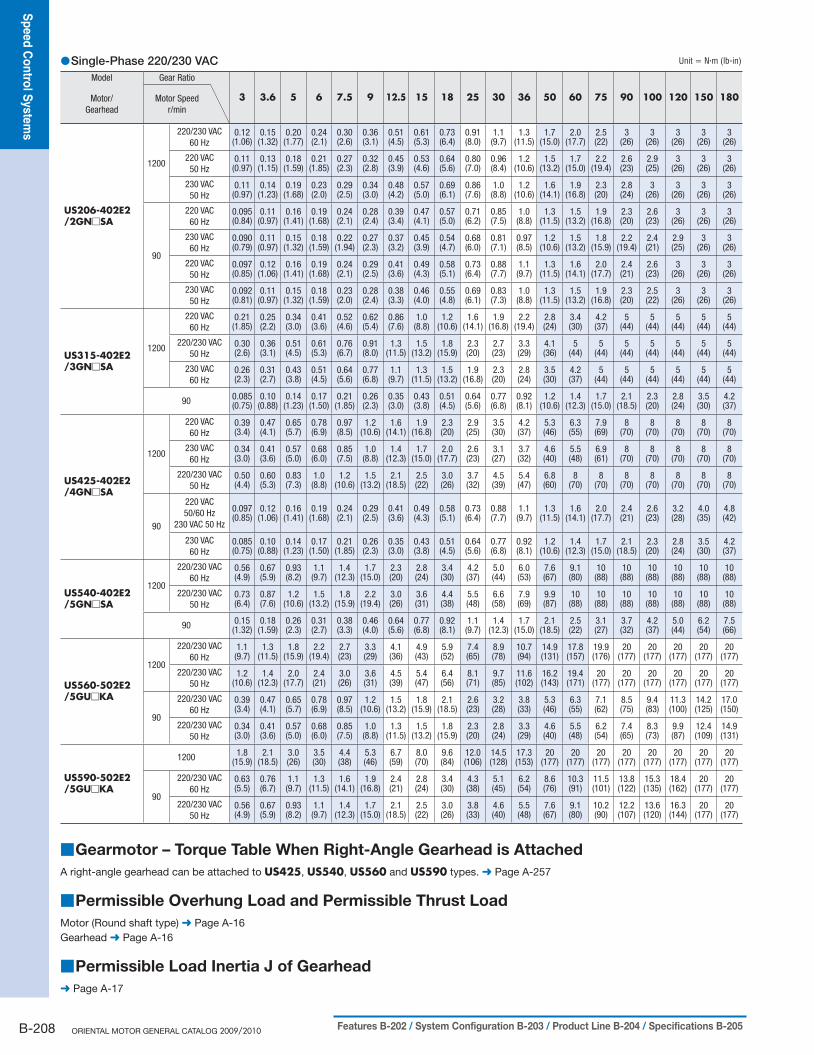
Single-Phase 220/230 VAC ● Unit = N·m (lb-in)
Model Gear Ratio
3 3.6 5 6 7.5 9 12.5 15 18 25 30 36 50 60 75 90 100 120 150 180Motor/Gearhead
Motor Speedr/min
US206-402E2/2GN□SA
1200
220/230 VAC60 Hz
0.12 0.15 0.20 0.24 0.30 0.36 0.51 0.61 0.73 0.91 1.1 1.3 1.7 2.0 2.5 3 3 3 3 3(1.06) (1.32) (1.77) (2.1) (2.6) (3.1) (4.5) (5.3) (6.4) (8.0) (9.7) (11.5) (15.0) (17.7) (22) (26) (26) (26) (26) (26)
220 VAC50 Hz
0.11 0.13 0.18 0.21 0.27 0.32 0.45 0.53 0.64 0.80 0.96 1.2 1.5 1.7 2.2 2.6 2.9 3 3 3(0.97) (1.15) (1.59) (1.85) (2.3) (2.8) (3.9) (4.6) (5.6) (7.0) (8.4) (10.6) (13.2) (15.0) (19.4) (23) (25) (26) (26) (26)
230 VAC50 Hz
0.11 0.14 0.19 0.23 0.29 0.34 0.48 0.57 0.69 0.86 1.0 1.2 1.6 1.9 2.3 2.8 3 3 3 3(0.97) (1.23) (1.68) (2.0) (2.5) (3.0) (4.2) (5.0) (6.1) (7.6) (8.8) (10.6) (14.1) (16.8) (20) (24) (26) (26) (26) (26)
90
220 VAC60 Hz
0.095 0.11 0.16 0.19 0.24 0.28 0.39 0.47 0.57 0.71 0.85 1.0 1.3 1.5 1.9 2.3 2.6 3 3 3(0.84) (0.97) (1.41) (1.68) (2.1) (2.4) (3.4) (4.1) (5.0) (6.2) (7.5) (8.8) (11.5) (13.2) (16.8) (20) (23) (26) (26) (26)
230 VAC60 Hz
0.090 0.11 0.15 0.18 0.22 0.27 0.37 0.45 0.54 0.68 0.81 0.97 1.2 1.5 1.8 2.2 2.4 2.9 3 3(0.79) (0.97) (1.32) (1.59) (1.94) (2.3) (3.2) (3.9) (4.7) (6.0) (7.1) (8.5) (10.6) (13.2) (15.9) (19.4) (21) (25) (26) (26)
220 VAC50 Hz
0.097 0.12 0.16 0.19 0.24 0.29 0.41 0.49 0.58 0.73 0.88 1.1 1.3 1.6 2.0 2.4 2.6 3 3 3(0.85) (1.06) (1.41) (1.68) (2.1) (2.5) (3.6) (4.3) (5.1) (6.4) (7.7) (9.7) (11.5) (14.1) (17.7) (21) (23) (26) (26) (26)
230 VAC50 Hz
0.092 0.11 0.15 0.18 0.23 0.28 0.38 0.46 0.55 0.69 0.83 1.0 1.3 1.5 1.9 2.3 2.5 3 3 3(0.81) (0.97) (1.32) (1.59) (2.0) (2.4) (3.3) (4.0) (4.8) (6.1) (7.3) (8.8) (11.5) (13.2) (16.8) (20) (22) (26) (26) (26)
US315-402E2/3GN□SA
1200
220 VAC60 Hz
0.21 0.25 0.34 0.41 0.52 0.62 0.86 1.0 1.2 1.6 1.9 2.2 2.8 3.4 4.2 5 5 5 5 5(1.85) (2.2) (3.0) (3.6) (4.6) (5.4) (7.6) (8.8) (10.6) (14.1) (16.8) (19.4) (24) (30) (37) (44) (44) (44) (44) (44)
220/230 VAC50 Hz
0.30 0.36 0.51 0.61 0.76 0.91 1.3 1.5 1.8 2.3 2.7 3.3 4.1 5 5 5 5 5 5 5(2.6) (3.1) (4.5) (5.3) (6.7) (8.0) (11.5) (13.2) (15.9) (20) (23) (29) (36) (44) (44) (44) (44) (44) (44) (44)
230 VAC60 Hz
0.26 0.31 0.43 0.51 0.64 0.77 1.1 1.3 1.5 1.9 2.3 2.8 3.5 4.2 5 5 5 5 5 5(2.3) (2.7) (3.8) (4.5) (5.6) (6.8) (9.7) (11.5) (13.2) (16.8) (20) (24) (30) (37) (44) (44) (44) (44) (44) (44)
90 0.085 0.10 0.14 0.17 0.21 0.26 0.35 0.43 0.51 0.64 0.77 0.92 1.2 1.4 1.7 2.1 2.3 2.8 3.5 4.2(0.75) (0.88) (1.23) (1.50) (1.85) (2.3) (3.0) (3.8) (4.5) (5.6) (6.8) (8.1) (10.6) (12.3) (15.0) (18.5) (20) (24) (30) (37)
US425-402E2/4GN□SA
1200
220 VAC60 Hz
0.39 0.47 0.65 0.78 0.97 1.2 1.6 1.9 2.3 2.9 3.5 4.2 5.3 6.3 7.9 8 8 8 8 8(3.4) (4.1) (5.7) (6.9) (8.5) (10.6) (14.1) (16.8) (20) (25) (30) (37) (46) (55) (69) (70) (70) (70) (70) (70)
230 VAC60 Hz
0.34 0.41 0.57 0.68 0.85 1.0 1.4 1.7 2.0 2.6 3.1 3.7 4.6 5.5 6.9 8 8 8 8 8(3.0) (3.6) (5.0) (6.0) (7.5) (8.8) (12.3) (15.0) (17.7) (23) (27) (32) (40) (48) (61) (70) (70) (70) (70) (70)
220/230 VAC50 Hz
0.50 0.60 0.83 1.0 1.2 1.5 2.1 2.5 3.0 3.7 4.5 5.4 6.8 8 8 8 8 8 8 8(4.4) (5.3) (7.3) (8.8) (10.6) (13.2) (18.5) (22) (26) (32) (39) (47) (60) (70) (70) (70) (70) (70) (70) (70)
90
220 VAC50/60 Hz
230 VAC 50 Hz
0.097 0.12 0.16 0.19 0.24 0.29 0.41 0.49 0.58 0.73 0.88 1.1 1.3 1.6 2.0 2.4 2.6 3.2 4.0 4.8(0.85) (1.06) (1.41) (1.68) (2.1) (2.5) (3.6) (4.3) (5.1) (6.4) (7.7) (9.7) (11.5) (14.1) (17.7) (21) (23) (28) (35) (42)
230 VAC60 Hz
0.085 0.10 0.14 0.17 0.21 0.26 0.35 0.43 0.51 0.64 0.77 0.92 1.2 1.4 1.7 2.1 2.3 2.8 3.5 4.2(0.75) (0.88) (1.23) (1.50) (1.85) (2.3) (3.0) (3.8) (4.5) (5.6) (6.8) (8.1) (10.6) (12.3) (15.0) (18.5) (20) (24) (30) (37)
US540-402E2/5GN□SA
1200
220/230 VAC60 Hz
0.56 0.67 0.93 1.1 1.4 1.7 2.3 2.8 3.4 4.2 5.0 6.0 7.6 9.1 10 10 10 10 10 10(4.9) (5.9) (8.2) (9.7) (12.3) (15.0) (20) (24) (30) (37) (44) (53) (67) (80) (88) (88) (88) (88) (88) (88)
220/230 VAC50 Hz
0.73 0.87 1.2 1.5 1.8 2.2 3.0 3.6 4.4 5.5 6.6 7.9 9.9 10 10 10 10 10 10 10(6.4) (7.6) (10.6) (13.2) (15.9) (19.4) (26) (31) (38) (48) (58) (69) (87) (88) (88) (88) (88) (88) (88) (88)
90 0.15 0.18 0.26 0.31 0.38 0.46 0.64 0.77 0.92 1.1 1.4 1.7 2.1 2.5 3.1 3.7 4.2 5.0 6.2 7.5(1.32) (1.59) (2.3) (2.7) (3.3) (4.0) (5.6) (6.8) (8.1) (9.7) (12.3) (15.0) (18.5) (22) (27) (32) (37) (44) (54) (66)
US560-502E2/5GU□KA
1200
220/230 VAC60 Hz
1.1 1.3 1.8 2.2 2.7 3.3 4.1 4.9 5.9 7.4 8.9 10.7 14.9 17.8 19.9 20 20 20 20 20(9.7) (11.5) (15.9) (19.4) (23) (29) (36) (43) (52) (65) (78) (94) (131) (157) (176) (177) (177) (177) (177) (177)
220/230 VAC50 Hz
1.2 1.4 2.0 2.4 3.0 3.6 4.5 5.4 6.4 8.1 9.7 11.6 16.2 19.4 20 20 20 20 20 20(10.6) (12.3) (17.7) (21) (26) (31) (39) (47) (56) (71) (85) (102) (143) (171) (177) (177) (177) (177) (177) (177)
90
220/230 VAC60 Hz
0.39 0.47 0.65 0.78 0.97 1.2 1.5 1.8 2.1 2.6 3.2 3.8 5.3 6.3 7.1 8.5 9.4 11.3 14.2 17.0(3.4) (4.1) (5.7) (6.9) (8.5) (10.6) (13.2) (15.9) (18.5) (23) (28) (33) (46) (55) (62) (75) (83) (100) (125) (150)
220/230 VAC50 Hz
0.34 0.41 0.57 0.68 0.85 1.0 1.3 1.5 1.8 2.3 2.8 3.3 4.6 5.5 6.2 7.4 8.3 9.9 12.4 14.9(3.0) (3.6) (5.0) (6.0) (7.5) (8.8) (11.5) (13.2) (15.9) (20) (24) (29) (40) (48) (54) (65) (73) (87) (109) (131)
US590-502E2/5GU□KA
1200 1.8 2.1 3.0 3.5 4.4 5.3 6.7 8.0 9.6 12.0 14.5 17.3 20 20 20 20 20 20 20 20(15.9) (18.5) (26) (30) (38) (46) (59) (70) (84) (106) (128) (153) (177) (177) (177) (177) (177) (177) (177) (177)
90
220/230 VAC60 Hz
0.63 0.76 1.1 1.3 1.6 1.9 2.4 2.8 3.4 4.3 5.1 6.2 8.6 10.3 11.5 13.8 15.3 18.4 20 20(5.5) (6.7) (9.7) (11.5) (14.1) (16.8) (21) (24) (30) (38) (45) (54) (76) (91) (101) (122) (135) (162) (177) (177)
220/230 VAC50 Hz
0.56 0.67 0.93 1.1 1.4 1.7 2.1 2.5 3.0 3.8 4.6 5.5 7.6 9.1 10.2 12.2 13.6 16.3 20 20(4.9) (5.9) (8.2) (9.7) (12.3) (15.0) (18.5) (22) (26) (33) (40) (48) (67) (80) (90) (107) (120) (144) (177) (177)
Gearmotor – Torque Table When Right-Angle Gearhead is Attached ■
A right-angle gearhead can be attached to US425, US540, US560 and US590 types. ➜ Page A-257
Permissible Overhung Load and Permissible Thrust Load ■
Motor (Round shaft type) ➜ Page A-16
Gearhead ➜ Page A-16
Permissible Load Inertia J of Gearhead ■
➜ Page A-17

Sp
eed
Co
ntro
l Syste
ms
Intro
du
ctio
nA
C In
pu
tBX
AC
Inp
ut
BLF
AC
Inp
ut
BLU
AC
Inp
ut
FBL
DC
Inp
ut
BLH
BH
FFE1
00/
FE200
ES01/
ES02
US
Insta
llatio
n
Bru
sh
less M
oto
r Syste
ms
AC
Mo
tor S
yste
ms
B-209Characteristics B-209 / Dimensions B-210 / Connection and Operation B-216 / Motor and Control Unit Combinations B-217
Speed – Torque Characteristics ■
US206-401U2US206-001U2
20
0
40
60
80
0
2
4
6
8
10
18001500100050090Speed [r/min]
Torq
ue [m
N·m
]
Torq
ue [o
z-in
]
12 115 VACSafe Operation Line
110 VAC115 VAC
Permissible Torque whenGearhead is Attached
110 VACSafe Operation Line
US206-402E2US206-002E2
1800100050090Speed [r/min]
Permissible Torque whenGearhead is Attached
230 VAC/50 HzSafe Operation Line
230 VAC/60 HzSafe Operation Line
220 VAC/50 HzSafe Operation Line
220 VAC/60 HzSafe Operation Line
1500
50 Hz 230 VAC60 Hz 230 VAC50 Hz 220 VAC60 Hz 220 VAC
20
40
60
80
Torq
ue [m
N·m
]
0 0
2
4
6
8
10
Torq
ue [o
z-in
]
12
US315-401U2US315-001U2
Permissible Torque whenGearhead is Attached
80
40
120
160
200
18001500100050090Speed [r/min]
Safe-Operation Line 110 VAC115 VAC
0 0
5
10
15
20
25
Torq
ue [m
N·m
]
Torq
ue [o
z-in
]
US315-402E2US315-002E2
230 VAC, 60 Hz Safe-Operation Line50 Hz Safe-Operation Line
90
Permissible Torque whenGearhead is Attached
180015001000500
220 VAC/60 Hz Safe-Operation Line
Speed [r/min]
80
40
120
160
200
0
50 Hz 230 VAC60 Hz 230 VAC50 Hz 220 VAC60 Hz 220 VAC
0
5
10
15
20
25
Torq
ue [m
N·m
]
Torq
ue [o
z-in
]
US425-401U2US425-001U2
90
200
100
250
300Safe-Operation Line
Permissible Torque whenGearhead is Attached
180015001000500Speed [r/min]
50
150
110 VAC115 VAC
30
35
40
0 0
5
10
15
20
25
Torq
ue [m
N·m
]
Torq
ue [o
z-in
]
45
US425-402E2US425-002E2
90 18001000500 1500Speed [r/min]
200
100
250
300
50
150
50 Hz 230 VAC60 Hz 230 VAC50 Hz 220 VAC60 Hz 220 VAC
30
35
40
45
0 0
5
10
15
20
25
Torq
ue [m
N·m
]
Torq
ue [o
z-in
]
60 Hz Safe-Operation Line
50 Hz Safe-Operation LinePermissible Torque whenGearhead is Attached
US540-401U2US540-001U2
0.4
0.5
0.3
0.2
0.1
180015001000500Speed [r/min]
90
110 VAC115 VAC
Safe-Operation LinePermissible Torque whenGearhead is Attached
60
70
0 0
10
20
30
40
50
Torq
ue [N
·m]
Torq
ue [o
z-in
]
US540-402E2US540-002E2
0.4
0.3
0.2
0.1
0
0.5
0
10
20
30
40
50
60
70
Torq
ue [N
·m]
Torq
ue [o
z-in
]
18001500100050090Speed [r/min]
Permissible Torque whenGearhead is Attached 60 Hz Safe-Operation Line
50 Hz Safe-Operation Line
50 Hz 230 VAC60 Hz 230 VAC50 Hz 220 VAC60 Hz 220 VAC
US560-501U2US560-001U2
1.0
0.8
0.6
0.4
0.2
180015001000500Speed [r/min]
90
Permissible Torque whenGearhead is Attached
110 VAC115 VAC
Safe-Operation Line
120
140
0 0
20
40
60
80
100
Torq
ue [N
·m]
Torq
ue [o
z-in
]

B-210 ORIENTAL MOTOR GENERAL CATALOG 2009/2010 Features B-202 / System Configuration B-203 / Product Line B-204 / Specifications B-205
Sp
eed
Co
ntro
l Syste
ms
Dimensions ■ Unit = mm (in.)
Mounting screws are included with gearheads. Dimensions for mounting screws ● ➜ Page A-310
6 W (1/125 HP) ●Motor/Gearhead ◇
Model Motor Model Gearhead Model Gear Ratio L DXF
US206-401U2US206-402E2
USM206-401W2USM206-402W2 2GN□SA
3∼18 30 (1.18) A486AU25∼180 40 (1.57) A486BU
Enter the gear ratio in the box ( ● □) within the model name.Mass: Motor 0.8 kg (1.76 lb.)
Gearhead 0.4 kg (0.88 lb.)
Leads 250 mm (10 in.) LengthW/connector
Housing: 5557-10R (MOLEX)
ϕ60
(ϕ2.
36)
ϕ47
(ϕ1.
85)
7(0.28)
10 (0.39) 75 (2.95)
60 (2.36)
60 ( 2
.36)
5 (0.20) max.
22.5˚
Protective Earth Terminal M4
7.43
7 ( 0
.293
)
ϕ24
(ϕ0.
94)
10 ( 0
.39)
32(1.26)
L
5(0.20)
12.7(0.50)
ϕ7.937−0.015
ϕ0.3125−0.0006 (5/16")0
0
4×ϕ4.5 (ϕ0.177) Thru
70±0.5
(2.76±0.02)
15.5
( 0.6
1)
21.5 (0.85)
Protective Earth TerminalM4
Detail Drawing of Protective Earth Terminal
Shaft Section of Round Shaft Type ◇The motor's dimensions (excluding the shaft section) are the same
as those of the pinion shaft types.
US206-001U2, US206-002E2Motor: USM206-001W2, USM206-002W2Mass: 0.8 kg (1.76 lb.)
A487
2(0.08)
24(0.94)
□60
( □2.
36)
22.5˚
5 (0.20) max.
ϕ6−
0.01
2 ( ϕ
0.23
62−
0.00
05)
00
ϕ54
−0.
030
( ϕ2.
1260
−0.
0012
)0
0
4×ϕ4.5 (ϕ0.177) Thru
70±0.5 (2.76±0.02)
Protective Earth Terminal M4
Decimal Gearhead ◇Can be connected to US206 pinion shaft type.
2GN10XSMass: 0.2 kg (0.44 lb.)
A003
38.5 (1.51)
26(1.02)
12.5(0.49)
2(0.08)
70±0.5
(2.76±0.02)
□60
( □2.
36)
4×ϕ4.5 (ϕ0.177) Thru
( ϕ 2.1
260−
0.00
12)
ϕ54
−0.
030
0
0
US560-502E2US560-002E2
18001500100050090
50 Hz Safe-Operation Line
60 Hz Safe-Operation Line
Speed [r/min]
1.0
0.8
0.6
0.4
0.2
0
50 Hz 230 VAC60 Hz 230 VAC50 Hz 220 VAC60 Hz 220 VAC
140
120
0
20
40
60
80
100
Torq
ue [N
·m]
Torq
ue [o
z-in
]
Permissible Torque whenGearhead is Attached
US590-501U2US590-001U2
1.0
0.8
0.6
0.4
0.2
18001500100050090Speed [r/min]
Safe-Operation Line
Permissible Torque whenGearhead is Attached
110 VAC115 VAC140
120
0 0
20
40
60
80
100
Torq
ue [N
·m]
Torq
ue [o
z-in
]
US590-502E2US590-002E2
1800100050090
50 Hz Safe-Operation Line
220 VAC, 60 Hz Safe-Operation Line
230 VAC, 60 Hz Safe-Operation Line
Permissible Torque whenGearhead is Attached
1500Speed [r/min]
1.2
1.0
0.8
0.4
0.2
0
0.6
50 Hz 230 VAC60 Hz 230 VAC50 Hz 220 VAC60 Hz 220 VAC
120
160
140
0
20
40
60
80
100
Torq
ue [N
·m]
Torq
ue [o
z-in
]
180

Sp
eed
Co
ntro
l Syste
ms
Intro
du
ctio
nA
C In
pu
tBX
AC
Inp
ut
BLF
AC
Inp
ut
BLU
AC
Inp
ut
FBL
DC
Inp
ut
BLH
BH
FFE1
00/
FE200
ES01/
ES02
US
Insta
llatio
n
Bru
sh
less M
oto
r Syste
ms
AC
Mo
tor S
yste
ms
B-211Characteristics B-209 / Dimensions B-210 / Connection and Operation B-216 / Motor and Control Unit Combinations B-217
15 W (1/50 HP) ●Motor/Gearhead ◇
Model Motor Model Gearhead Model Gear Ratio L DXF
US315-401U2US315-402E2
USM315-401W2USM315-402W2 3GN□SA
3∼18 32 (1.26) A488AU25∼180 42 (1.65) A488BU
Enter the gear ratio in the box ( ● □) within the model name.Mass: Motor 1.2 kg (2.6 lb.)
Gearhead 0.55 kg (1.21 lb.)
8.82
5 ( 0
.347
)32(1.26)
L
5(0.20)
12.7(0.50)
ϕ30
(ϕ1.
18)
15 ( 0
.59)
ϕ9.525−0.015
ϕ0.3750−0.0006 (3/8")0
0
ϕ69
(ϕ2.
72)
ϕ47
(ϕ1.
85)
10 (0.39) 80 (3.15)7
(0.28)70 (2.76)
70 ( 2
.76)
22.5˚
5 (0.20) max.
Protective EarthTerminal M4
Leads 250 mm (10 in.) LengthW/connector
Housing: 5557-10R (MOLEX)
4×ϕ5.5 (ϕ0.217) Thru
82±0.5 (3.23±0.02)
16.5
( 0.6
5)
Detail Drawing of Protective Earth Terminal
21.5 (0.85)
Protective Earth TerminalM4
Shaft Section of Round Shaft Type ◇The motor's dimensions (excluding the shaft section) are the same
as those of the pinion shaft types.
US315-001U2, US315-002E2Motor: USM315-001W2, USM315-002W2Mass: 1.2 kg (2.6 lb.)
A489
2(0.08)
32(1.26)
□70
( □2.
76)
5 (0.20) max.
22.5˚
ϕ6−
0.01
2 ( ϕ
0.23
62−
0.00
05)
00
ϕ64
−0.
030
( ϕ2.
5197
−0.
0012
)0
0
4×ϕ5.5 (ϕ0.217) Thru
Protective Earth TerminalM4
82±0.5 (3.23±0.02)
Decimal Gearhead ◇Can be connected to US315 pinion shaft type.
3GN10XSMass: 0.3 kg (0.66 lb.)
A009
43 (1.69)
30(1.18)
13(0.51)
2(0.08)
82±0.5
(3.23±0.02)
□70
( □2.
76)
4×ϕ5.5 (ϕ0.217) Thru
( ϕ2.
5197
−0.
0012
)0
ϕ64
−0.
030
0

B-212 ORIENTAL MOTOR GENERAL CATALOG 2009/2010 Features B-202 / System Configuration B-203 / Product Line B-204 / Specifications B-205
Sp
eed
Co
ntro
l Syste
ms
Shaft Section of Round Shaft Type ◇The motor’s dimensions (excluding the shaft section) are the same
as those of the pinion shaft types.
US425-001U2, US425-002E2Motor: USM425-001W2, USM425-002W2Mass: 1.6 kg (3.5 lb.)
A491
Decimal Gearhead ◇Can be connected to US425 pinion shaft type.
4GN10XSMass: 0.4 kg (0.88 lb.)
A013
2(0.08)
32(1.26)
25(0.98)
□80
( □3.
15)
22.5˚
5 (0.20) max.
7 ( 0
.28)
ϕ8−
0.01
5 ( ϕ
0.31
50−
0.00
06)
00
ϕ73
−0.
030
( ϕ2.
8740
−0.
0012
)0
0
4×ϕ5.5 (ϕ0.217) Thru
94±0.5 (3.70±0.02)
Protective Earth TerminalM4
45.5 (1.79)
32(1.26)
13.5(0.53)
2(0.08)
□80
( □3.
15)
94±0.5
(3.70±0.02)
4×ϕ5.5 (ϕ0.217) Thru
ϕ73
−0.
030
( ϕ2.
8740
−0.
0012
)0
0
25 W (1/30 HP) ●Motor/Gearhead ◇
Model Motor Model Gearhead Model Gear Ratio L DXF
US425-401U2US425-402E2
USM425-401W2USM425-402W2 4GN□SA
3∼18 32 (1.26) A490AU25∼180 42.5 (1.67) A490BU
Enter the gear ratio in the box ( ● □) within the model name.Mass: Motor 1.6 kg (3.5 lb.)
Gearhead 0.65 kg (1.43 lb.)
Housing: 5557-10R (MOLEX)
Leads 250 mm (10 in.) LengthW/connector
10 (0.39) 85 (3.35)
80 (3.15)7
(0.28)
ϕ79
(ϕ3.
11)
ϕ47
(ϕ1.
85)
22.5˚
80 ( 3
.15)
5 (0.20) max.
Protective EarthTerminal M4
8.82
5 ( 0
.347
)32(1.26)
15 ( 0
.59)
ϕ34
(ϕ1.
34)
12.7(0.50)
L
6(0.24)
ϕ9.525−0.015
ϕ0.3750−0.0006 (3/8")0
0
4×ϕ5.5 (ϕ0.217) Thru
94±0.5 (3.70±0.02)
16.5
( 0.6
5)
21.5 (0.85)
Protective Earth TerminalM4
Detail Drawing of Protective Earth Terminal

Sp
eed
Co
ntro
l Syste
ms
Intro
du
ctio
nA
C In
pu
tBX
AC
Inp
ut
BLF
AC
Inp
ut
BLU
AC
Inp
ut
FBL
DC
Inp
ut
BLH
BH
FFE1
00/
FE200
ES01/
ES02
US
Insta
llatio
n
Bru
sh
less M
oto
r Syste
ms
AC
Mo
tor S
yste
ms
B-213Characteristics B-209 / Dimensions B-210 / Connection and Operation B-216 / Motor and Control Unit Combinations B-217
Shaft Section of Round Shaft Type ◇The motor’s dimensions (excluding the shaft section) are the same
as those of the pinion shaft types.
US540-001U2, US540-002E2Motor: USM540-001W2, USM540-002W2Mass: 2.6 kg (5.7 lb.)
A493
2(0.08)
37(1.46)
30(1.18)
9 ( 0
.35)
□90
( □3.
54)
22.5˚
5 (0.20) max.
Protective Earth TerminalM4
ϕ10
−0.
015
( ϕ0.
3937
−0.
0006
)0
0
ϕ83
−0.
035
( ϕ3.
2677
−0.
0014
)0
0
4×ϕ6.5 (ϕ0.256) Thru
104±0.5 (4.09±0.02)
Decimal Gearhead ◇Can be connected to US540 pinion shaft type.
5GN10XSMass: 0.6 kg (1.32 lb.)
A022
37(1.46)
18(0.71)
55 (2.17)
2(0.08)
□90
( □3.
54)
104±0.5
(4.09±0.02)
4×ϕ6.5 (ϕ0.256) Thru
ϕ83
−0.
035
( ϕ3.
2677
−0.
0014
)0
0
40 W (1/19 HP) ●Motor/Gearhead ◇
Model Motor Model Gearhead Model Gear Ratio L DXF
US540-401U2US540-402E2
USM540-401W2USM540-402W2 5GN□SA
3∼18 42 (1.65) A492AU25∼180 60 (2.36) A492BU
Enter the gear ratio in the box ( ● □) within the model name.Mass: Motor 2.6 kg (5.7 lb.)
Gearhead 1.5 kg (3.3 lb.)
11.4
( 0.4
5)
18 ( 0
.71)
ϕ36
(ϕ1.
42)
32(1.26)
4(0.16) 19
(0.75)
L
ϕ12.7−0.018
ϕ0.5000−0.0007 (1/2")0
0
ϕ89
(ϕ3.
50)
7.5(0.30)
ϕ47
(ϕ1.
85)
10 (0.39) 105 (4.13)
90 (3.54)
22.5˚
90 ( 3
.54)
5 (0.20) max.4×ϕ6.5 (ϕ0.256) Thru
104±0.5 (4.09±0.02)
Protective EarthTerminal M4
Leads 250 mm (10 in.) LengthW/connector
Housing: 5557-10R (MOLEX)
16.5
( 0.6
5)
21.5 (0.85)
Detail Drawing of Protective Earth Terminal
Protective Earth TerminalM4

B-214 ORIENTAL MOTOR GENERAL CATALOG 2009/2010 Features B-202 / System Configuration B-203 / Product Line B-204 / Specifications B-205
Sp
eed
Co
ntro
l Syste
ms
Shaft Section of Round Shaft Type ◇The motor's dimensions (excluding the shaft section) are the same
as those of the pinion shaft types.
US560-001U2, US560-002E2Motor: USM560-001W-1, USM560-002W-1Mass: 2.8 kg (6.2 lb.)
A495
US590-001U2, US590-002E2Motor: USM590-001W-1, USM590-002W-1Mass: 3.6 kg (7.9 lb.)
A497
30(1.18)
37(1.46)2
(0.08)
11 ( 0
.43)
□90
( □3.
54)
33(1.30)
ϕ12
−0.
018
( ϕ0.
4724
−0.
0007
)0
0
ϕ83
−0.
035
( ϕ3.
2677
−0.
0014
)0
0
4×ϕ6.5 (ϕ0.256) Thru
104±0.5
(4.09±0.02)
Decimal Gearhead ◇Can be connected to US560 or US590 pinion shaft types.
5GU10XKBMass: 0.6 kg (1.32 lb.)
A029
61 (2.40)
40 (1.57) 21(0.83)2
(0.08)
104±0.5
(4.09±0.02)
□90
( □3.
54)
4×ϕ10.8 (ϕ0.425) Thru
ϕ83
−0.
035
( ϕ3.
2677
−0.
0014
)0
0
60 W (1/12 HP) ●Motor/Gearhead ◇
Model Motor Model Gearhead Model L DXF
US560-501U2US560-502E2
USM560-501W-1USM560-502W-1 5GU□KA 150 (5.91) A494U
Enter the gear ratio in the box ( ● □) within the model name.Mass: Motor 2.8 kg (6.2 lb.)
Gearhead 1.5 kg (3.3 lb.)
□90
( □3.
54)
18.5
( 0.7
3)
7 (0.28)7.5 (0.30)
ϕ34
(ϕ1.
34)
18 ( 0
.71)28.58
(1.13)
42 (1.65)
L 65 (2.56) 38 (1.50)
Motor Cable ϕ11.2 (ϕ0.44), 250 mm (10 in.) LengthHousing: 5557-10R (MOLEX)
33(1.30)
90 (3.54)
90 ( 3
.54)
ϕ15.875−0.011
ϕ0.6250−0.0004 (5/8")0
0
4×ϕ6.5 (ϕ0.256) Thru
104±0.5
(4.09±0.02)
90 W (1/8 HP) ●Motor/Gearhead ◇
Model Motor Model Gearhead Model L DXF
US590-501U2US590-502E2
USM590-501W-1USM590-502W-1 5GU□KA 165 (6.50) A496U
Enter the gear ratio in the box ( ● □) within the model name.Mass: Motor 3.6 kg (7.9 lb.)
Gearhead 1.5 kg (3.3 lb.)
Key and Key Slot (The key is included with the gearhead) ◇
28.58±0.2
(1.125±0.008)4.763−0.03
(0.1875−0.0012)0
04.763 0(0.1875 0 )+0.0016
+0.040
2.74
3 0
( 0.1
08 0
)+
0.00
4
+0.
1
4.76
3−0.
03
( 0.1
875−
0.00
12)
0
0

Sp
eed
Co
ntro
l Syste
ms
Intro
du
ctio
nA
C In
pu
tBX
AC
Inp
ut
BLF
AC
Inp
ut
BLU
AC
Inp
ut
FBL
DC
Inp
ut
BLH
BH
FFE1
00/
FE200
ES01/
ES02
US
Insta
llatio
n
Bru
sh
less M
oto
r Syste
ms
AC
Mo
tor S
yste
ms
B-215Characteristics B-209 / Dimensions B-210 / Connection and Operation B-216 / Motor and Control Unit Combinations B-217
Control Unit ◇Common to US206, US315, US425 and US540 Types
USP206-1U2/USP206-2E2USP315-1U2/USP315-2E2USP425-1U2/USP425-2E2USP540-1U2/USP540-2E2Mass: 0.45 kg (0.99 lb.)
A498
Ground Lead 2000 mm (6.6 ft.) LengthUL Style 1007, AWG22
6×M3
50±0.5(1.97±0.02)
90±
0.5
( 3.5
4±0.
02)
Housing: 5559-10P (MOLEX)
4×ϕ3.5 (ϕ0.138)Thru
Cable 2000 mm (6.6 ft.) Length AWG18
90 (3.54) max.
Cable ϕ7.3 (ϕ0.29), 500 mm (20 in.) Length2×ϕ4.5 (ϕ0.177) Thru
60 (2.36)
90±
0.5
( 3.5
4±0.
02)
11.5 (0.45)76 (2.99)
100
( 3.9
4)
2 (0.08) 1.5 (0.06)
80 ( 3
.15)
52 (2.05)
6.32
( 0.2
5)Pi
tch
7.62
( 0.3
0)
Common to US560 and US590 Types
USP560-1U2/USP560-2E2USP590-1U2/USP590-2E2Mass: 0.5 kg (1.1 lb.)
A499
90 (3.54) max.76 (2.99)
100
( 3.9
4)2 (0.08)
2×ϕ4.5 (ϕ0.177) Thru
60 (2.36)
90±
0.5
( 3.5
4±0.
02)
Ground Lead 2000 mm (6.6 ft.) Length UL Style 1007, AWG22
Capacitor Leads 350 mm (14 in.) Length
Housing: 5559-10P (MOLEX)
Cable ϕ11.2 (ϕ0.44), 500 mm (20 in.) Length
7×M3
50±0.5(1.97±0.02)
90±
0.5
( 3.5
4±0.
02)
80 ( 3
.15)
52 (2.05)
6.32
( 0.2
5)Pi
tch
7.62
( 0.3
0)
4×ϕ3.5 (ϕ0.138)Thru
Cable 2000 mm (6.6 ft.) Length AWG18
11.5 (0.45)
1.5 (0.06)
Panel Cut-Out for Control Unit ◇Installation Method by Cutting a Square Hole
90±
0.2
( 3.5
4±0.
008)
Panel
53+1 0
2×M4 Screw2×M4 or 2×ϕ4.5 (ϕ0.177)
81+
1
0( 3
.19
0
)
+0.
04
(2.09 0 )+0.04
B-216 ORIENTAL MOTOR GENERAL CATALOG 2009/2010 Features B-202 / System Configuration B-203 / Product Line B-204 / Specifications B-205
Sp
eed
Co
ntro
l Syste
ms
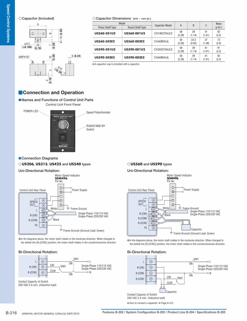
Capacitor (Included) ◇
6 (0.24)
A
CB
7( 0
.28)20
(0.79)10
( 0.3
9)AMP#187
ϕ4.3(ϕ0.169)
4( 0
.16)
B+15
( 0.5
9)
R10(R0.39)
Capacitor Dimensions ◇ Unit = mm (in.)
ModelCapacitor Model A B C
Massg (oz.)Pinion Shaft Type Round Shaft Type
US560-501U2 US560-001U2 CH180CFAUL2 58(2.28)
29(1.14)
41(1.61)
92(3.2)
US560-502E2 US560-002E2 CH40BFAUL 58(2.28)
23.5(0.93)
37(1.46)
73(2.6)
US590-501U2 US590-001U2 CH200CFAUL2 58(2.28)
29(1.14)
41(1.61)
91(3.2)
US590-502E2 US590-002E2 CH60BFAUL 58(2.28)
29(1.14)
41(1.61)
92(3.2)
A capacitor cap is included with a capacitor. ●
Connection Diagrams ●US206 ◇ , US315, US425 and US540 types
Uni-Directional Rotation:
Bi-Directional Rotation:
Motor Speed IndicatorSDM496Pin No.
1
10
11
2
Frame Ground
Power Supply
9
Contact Capacity of Switch250 VAC 5 A min. (Inductive load)
L
N (CW)
N (CCW)
CW
CCW
SW2
SW1L
N
ON
ON
Single-Phase 110/115 VACSingle-Phase 220/230 VAC
Control Unit Rear Panel
Frame Ground (Ground Lead: Green)
White
Black
SPEEDOUT
L
N (CW)
N (CCW)
FG
Single-Phase 110/115 VACSingle-Phase 220/230 VAC
●In the diagrams above, the motor shaft rotates in the clockwise direction. When changed to the dotted line [N (CCW)] position, the motor shaft rotates in the counterclockwise direction.
US560 ◇ and US590 types
Uni-Directional Rotation:
Bi-Directional Rotation:
Motor Speed IndicatorSDM496Pin No.
1
10
11
2
Frame Ground 9
Power SupplyControl Unit Rear Panel
Frame Ground (Ground Lead: Green)Capacitor
White
Black
SPEEDOUT
Single-Phase 110/115 VACSingle-Phase 220/230 VAC
L
N (CW)
N (COM)
N (CCW)
FG
Contact Capacity of Switch 250 VAC 5 A min. (Inductive load)
L
N (CW)
N (COM)
N (CCW)
SW1L
N
ON
ON
Single-Phase 110/115 VACSingle-Phase 220/230 VAC
CW
CCW
SW2
Capacitor
●In the diagrams above, the motor shaft rotates in the clockwise direction. When changed to the dotted line [N (CCW)] position, the motor shaft rotates in the counterclockwise direction.
How to connect a capacitor ● ➜ Page A-313
Connection and Operation ■
Names and Functions of Control Unit Parts ●Control Unit Front Panel
Speed Potentiometer
RUN/STAND-BYSwitch
POWER LED

Sp
eed
Co
ntro
l Syste
ms
Intro
du
ctio
nA
C In
pu
tBX
AC
Inp
ut
BLF
AC
Inp
ut
BLU
AC
Inp
ut
FBL
DC
Inp
ut
BLH
BH
FFE1
00/
FE200
ES01/
ES02
US
Insta
llatio
n
Bru
sh
less M
oto
r Syste
ms
AC
Mo
tor S
yste
ms
B-217Characteristics B-209 / Dimensions B-210 / Connection and Operation B-216 / Motor and Control Unit Combinations B-217
Rotation ◇Connect the motor lead wire connectors to the control unit. Then
connect the power cable [2 m (6.6 ft.), AWG18] to the AC power
supply. When the RUN/STAND-BY switch on the control unit is set
to RUN, the motor rotates in the clockwise (CW) direction as viewed
from the motor output shaft. Control units are set for clockwise
rotation at shipment. The rotation direction on the gearhead output
shaft may be the opposite direction of the motor shaft depending on
the gear ratio.
Changing Speed ◇When dial on the speed potentiometer located on the control unit is
turned in a clockwise direction, motor speed increases; when turned
in the counterclockwise direction, motor speed decreases.
Motor speed can be set and adjusted over a range of 90 to
1400 r/min at 50 Hz, 90 to 1600 r/min at 60 Hz.
Stopping ◇When the RUN/STAND-BY switch on the control unit is set to
STAND-BY, the motor stops. This switch is not a power ON/OFF
switch. If the motor is to be stopped for a long time, a separate
power ON/OFF switch should be installed.
Switching the Rotation Direction ◇US206 ● , US315, US425 and US540 types
(Capacitor is included in the control unit.)Uni-Directional Rotation:When the rotation direction of motor needs to be reversed, change
the terminal used for attaching the power cable, located at the rear
panel of control unit, from terminal N (CW) to terminal N (CCW).
The power cable connections are located at terminals L and N (CW)
when shipped. This should always be done with the power OFF.
Bi-Directional Rotation:Install an additional power switch (SW1) and CW/CCW switch
(SW2) as shown on page B-216, and use these switches to change
the rotation direction. Motor cannot be reversed instantaneously.
Turn SW1 off and wait until the motor has come to a complete stop
before switching SW2.
● US560 and US590 types (Connection of the included capacitor is necessary.)Uni-Directional Rotation:When the rotation direction of motor needs to be reversed, change
the terminal used for attaching the power cable, located at the rear
panel of control unit, from terminals N (CW)-N (COM) to terminals
N (COM)-N (CCW). The power cable connections are located at
terminals N (CW)-N (COM) when shipped. This should always be
done with the power OFF.
Bi-Directional Rotation:Install an additional power switch (SW1) and CW/CCW switch
(SW2) as shown on page B-216, and use these switches to change
the rotation direction. Motor cannot be reversed instantaneously.
Turn SW1 off and wait until the motor has come to a complete stop
before switching SW2.
List of Motor and Control Unit Combinations ■
Model name for motor and control unit combinations are shown below.
Operation Method ●There is a difference in operation method between the US206, US315, US425, US540 types and the US560, US590 types.
Single-Phase 110/115 VAC ●Output Power Model Motor Model Control Unit Model
6 W (1/125 HP)US206-401U2 USM206-401W2
USP206-1U2US206-001U2 USM206-001W2
15 W (1/50 HP)US315-401U2 USM315-401W2
USP315-1U2US315-001U2 USM315-001W2
25 W (1/30 HP)US425-401U2 USM425-401W2
USP425-1U2US425-001U2 USM425-001W2
40 W (1/19 HP)US540-401U2 USM540-401W2
USP540-1U2US540-001U2 USM540-001W2
60 W (1/12 HP)US560-501U2 USM560-501W-1
USP560-1U2US560-001U2 USM560-001W-1
90 W (1/8 HP)US590-501U2 USM590-501W-1
USP590-1U2US590-001U2 USM590-001W-1
Single-Phase 220/230 VAC ●Output Power Model Motor Model Control Unit Model
6 W (1/125 HP)US206-402E2 USM206-402W2
USP206-2E2US206-002E2 USM206-002W2
15 W (1/50 HP)US315-402E2 USM315-402W2
USP315-2E2US315-002E2 USM315-002W2
25 W (1/30 HP)US425-402E2 USM425-402W2
USP425-2E2US425-002E2 USM425-002W2
40 W (1/19 HP)US540-402E2 USM540-402W2
USP540-2E2US540-002E2 USM540-002W2
60 W (1/12 HP)US560-502E2 USM560-502W-1
USP560-2E2US560-002E2 USM560-002W-1
90 W (1/8 HP)US590-502E2 USM590-502W-1
USP590-2E2US590-002E2 USM590-002W-1

B-218 ORIENTAL MOTOR GENERAL CATALOG 2009/2010 Features B-202 / System Configuration B-203 / Product Line B-204 / Specifications B-205
Sp
eed
Co
ntro
l Syste
ms
Accessories (Sold separately) ■
Extension Cables ●Extension cables for connecting the US Series motor and control unit. Two types are available, depending on the motor output power.
The maximum extension length is 4.75 m (15.6 ft.).
Applicable Motors ◇US206 ● , US315, US425 and US540 Types
Model Cable Length: L [m (ft.)]CC01SU05 1 (3.3)CC02SU05 2 (6.6)CC03SU05 3 (9.8)CC04SU05 4 (13.1)
Dimensions ● Unit = mm (in.)
L
Housing: 5559-10P (MOLEX)Motor Side Control Unit Side
Housing: 5557-10R (MOLEX)
ϕ7.8 (ϕ0.31)
Applicable Motors ◇US560 ● and US590 Types
Model Cable Length: L [m (ft.)]CC01SU07 1 (3.3)CC02SU07 2 (6.6)CC03SU07 3 (9.8)CC04SU07 4 (13.1)
Dimensions ● Unit = mm (in.)
L
ϕ11.2 (ϕ0.44)
Housing: 5559-10P (MOLEX)Motor Side Control Unit Side
Housing: 5557-10R (MOLEX)