linear & rotary actuators e-117 - orientalmotor.com · high rigidity hollow rotary table with...
TRANSCRIPT

E-117
Linear & Rotary Actuators E-117
Electric
Linear
Slides
Overview,
Product
Series
AREAS
AREAC
ARDG
DRL
Electric
Cylinders
Hollow
Rotary
Actuators
Accessories
DG Series
AR Equipped
Linear & Rotary Actuators
Hollow Rotary Actuators
Page
DG Series AR Equipped ······················ E-118
E-118
E-118
ORIENTAL MOTOR GENERAL CATALOG 2015/2016
Page Features E-118 / System Configuration E-127 / Product Line E-129 / Specifications E-130
Dimensions E-133 / Actuator and Driver Combinations E-137
Hollow Rotary Actuators
DG Series AR Series Equipped
●For detailed information about regulations and standards, please see the Oriental Motor website.
View Expanded Product Information, Specifications, CAD, Accessories & more online.Visit www.orientalmotor.com/catalog or use the QR code and select "DG Series".
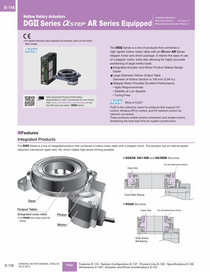
The DG Series is a line of products that combines a high rigidity hollow rotary table with an AR Series stepper motor and driver package. It retains the ease of use of a stepper motor, while also allowing for highly accurate positioning of large inertia loads.
• Integrated Actuator and Motor Product Makes Design Easier
• Large-Diameter Hollow Output Table Diameter of Hollow Section is 100 mm (3.94 in.)
• Stepper Motor Provides Excellent Performance• Agile Responsiveness• Stability at Low Speeds• Tuning-Free
What is FLEX?
FLEX is the collective name for products that support I/O control, Modbus (RTU) control, and FA network control via network converters.These products enable simple connection and simple control, shortening the total lead time for system construction.
<Additional Information>•Technical reference ➜ Page H-1•Regulations & Standards ➜ Page I-2
■Features
Integrated Products
The DG Series is a line of integrated product that combines a hollow rotary table with a stepper motor. The actuator has an internal speed reduction mechanism (gear ratio 18), which makes high power driving possible.
Motor
Pinion
Output Table
Gear
(Integrated cross roller) ● The DG60 uses a deep-groove ball bearing
● DG85R, DG130R and DG200R Structure
Cross-Roller Bearing
The red-tinted area is driven.
Output Table
● DG60 Structure
The red-tinted area is driven.
Deep-Groove Ball Bearing
Output Table

E-119
Linear & Rotary Actuators E-119
Electric
Linear
Slides
Overview,
Product
Series
AREAS
AREAC
ARDG
DRL
Electric
Cylinders
Hollow
Rotary
Actuators
Accessories
CAD DataManuals
www.orientalmotor.com Technical Support
TEL: (800) 468-3982E-mail: [email protected]
Simplified Design
Equipment tables and arms can be installed directly on the output table. Compared to when using mechanical components such as a belt and pulley, this save the hassle and cost of designing such a system.
Motor + Mechanical Component(Designed and arranged separately)
DG Series(Integrated product)
Large-Diameter, Hollow Output Table Makes Simple Wiring and Piping Possible
The large diameter hollow hole (through-hole) helps reduce the complexity of wiring and piping, thus simplifying equipment design.
● Filling equipment with piped-in liquid
ϕ100 mm(ϕ3.94 in.)
□20
0 m
m (□
7.87
in.)
Example: DG200R
Frame Size [mm (in.)] Diameter of Hollow Section [mm (in.)]DG60 60 (2.36) 28 (1.1)DG85R 85 (3.35) 33 (1.3)DG130R 130 (5.12) 62 (2.44)DG200R 200 (7.87) 100 (3.94)
High Load and High Rigidity
The DG Series uses a cross-roller bearing✽ on the output table, which allows for both high load and high rigidity.
✽Excludes the DG60
<Output Power>Maximum Permissible Torque 50 N·m (442.5 lb-in)
<Rigidity>Maximum Permissible Axial Load 4000 N (900 lb-in)Maximum Permissible Moment 100 N·m (885 lb-in)The received permissible moment increases as the frame size increases, but the displacement caused by the load moment decreases.
Distance from centerof rotation L [mm]
Arm
F [N
]
Disp
lace
men
t [μ
m]
300
250
200
150
100
50
00 20 40 60 80 100
DG130R
DG85R
DG200R
DG60
Disp
lace
men
t [μ
m]
Disp
lace
men
t [×
10-3
in.]
4
2
0
6
8
10 High Permissible Moment
Displacement at distance L = 200 mm (7.87 in.)from center of rotation
High
Rigi
dity (
Small
Disp
lacem
ent)
Moment Load [N·m]
Moment Load [lb-in]0 200 400 600 800
[Example Operation]Product Name : DG200R-ARAC2-3Power Supply Input : 230 VAC
Load Mass 91 kg (200.2 lb.) (6 load pieces + table): Load 10 kg/piece (22 lb./piece) × 6 pieces: Table 31 kg (68.2 lb.)
(Diameter 500 mm (19.7 in.), thickness 20 mm (0.79 in.), iron)
Overhung Distance : 160 mm (6.3 in.)Installation Direction : Horizontal
Table Mass 31 kg (68.2 lb.)
Load 10 kg (22 lb.) × 6 pieces
10 kg (22 lb.)
10 kg(22 lb.)
10 kg (22 lb.)
10 kg(22 lb.)
10 kg (22 lb.)
10 kg(22 lb.)
ϕ500 mm (ϕ19.7 in.)
Total Mass 91 kg (200.2 lb.)
●High LoadThe axial load for a total mass of 91 kg (200.2 lb.) is 893 N (201 lb.).[10 kg (22 lb.) × 6 pieces + 31 kg (68.2 lb.)] × 9.807 m/s2 893 N (201 lb.)The permissible axial load of the DG200R is 4000 N (900 lb.), so this is within the permissible value.
High Load Driving is Possible
●High RigidityWhen a 10 kg (22 lb.) load is placed 160 mm (6.3 in.) from the center of the the table, the moment is 15.7 N·m (139 lb-in).10 kg (22 lb.) × 9.807 m/s2 × 0.16 m (6.3 in.) 15.7 N·m (139 lb-in)The permissible moment of the DG200R is 100 N·m (885 lb-in), so this is within the permissible value.
160 mm (6.3 in.)
10 kg (22 lb.)
The DG Series can drive even with a large load that is away from the table center.
High Positioning Accuracy with Non-Backlash
● Non-Backlash ● Repetitive Positioning Accuracy ±15 arcsec (±0.004˚)
NoteThe repetitive positioning accuracy is measured at a constant temperature (normal temperature) under a constant load.

E-120
E-120Hollow Rotary ActuatorsDG Series
ORIENTAL MOTOR GENERAL CATALOG 2015/2016
Page Features E-118 / System Configuration E-127 / Product Line E-129 / Specifications E-130
Dimensions E-133 / Actuator and Driver Combinations E-137
Quick Positioning through Agile Responsiveness
By utilizing the high responsiveness of the stepper motor, quick short distance positioning is possible.
Stepper motors operate synchronously with pulse commands and generate high torque with a compact body, and offer excellent acceleration performance and response.
Start Positioning Completion
Operation Commands
Start Signal
Positioning Completion Signal
Actual Movement
[Example Operation]Product Name : DG200R-ARAC2-3Power Supply Input : 230 VAC
Load Mass 91 kg (200.2 lb.) (6 load pieces + table): Load 10 kg/piece (22 lb./piece) × 6 pieces: Table 31 kg (68.2 lb.)
(Diameter 500 mm (19.7 in.), thickness 20 mm (0.79 in.), iron)
Installation Direction : HorizontalTraveling Amount 60˚
Table Mass 31 kg (68.2 lb.)
Load 10 kg (22 lb.) × 6 pieces
10 kg(22 lb.)
10 kg(22 lb.)
10 kg(22 lb.)
10 kg(22 lb.)
10 kg(22 lb.)
10 kg(22 lb.)
ϕ500 mm (ϕ19.7 in.)
Total Mass 91 kg (200.2 lb.)
60˚
Total inertia of table and load = 2633 × 10-3 kg·m2 (144000 oz-in2)
●Quick PositioningWith the DG200R, 60˚ rotation of a total mass of 91 kg (200.2 lb.) is possible in 0.59 seconds.
The positioning time can be inferred using catalog data.
020000 6000040000
1.4
1.2
1.0
0.8
1.6
0.6
0.4
0.2
0 100000 200000 300000Load Inertia JL [oz-in2]
Load Inertia JL [×10–4 kg·m2]
Posi
tioni
ng T
ime
[ s]
0
180˚
90˚
60˚45˚30˚
15˚
60˚ rotation is possible in 0.59 seconds.DG200R
Load Inertia – Positioning Time (Reference value)
Quick positioning is possible even with large loads.
Low Vibration Even at Low Speed
Thanks to the microstep drive system and smooth drive function✽ of the stepper motor, resolution can be improved without mechanical elements such as a speed reduction mechanism. As a result, speed fluctuation is minimal even at low speeds, leading to improved stability.
✽About the Smooth Drive FunctionThe smooth drive function automatically microsteps based on the same traveling amount and traveling speed used in the full step mode, without changing the pulse input settings.
Tuning-Free
The stepper motor uses open loop control and does not require gain adjustment, so even when the load fluctuates, the movement exactly as set is obtained tuning-free.
No Hunting
Thanks to the open loop control of the stepper motor, there is no "hunting", the minute shaft movements that occur during stopping. Even when a large inertia load is transported, the stop position is accurately held.
Home Sensor Set is Available as an Accessory
Because the parts necessary for return-to-home operations are available as an accessory set (sold separately), the time for designing, fabricating and procuring parts related to sensor installation is reduced.
Shield Plate
Sensor
Sensor Installation Example
Installation Pedestals are Available as an Accessory
Accessory installation pedestals (sold separately) are available to make installing the DG Series easy.
Application Example Mounting Pedestals

E-121
Linear & Rotary Actuators E-121
Electric
Linear
Slides
Overview,
Product
Series
AREAS
AREAC
ARDG
DRL
Electric
Cylinders
Hollow
Rotary
Actuators
Accessories
CAD DataManuals
www.orientalmotor.com Technical Support
TEL: (800) 468-3982E-mail: [email protected]
■Applications
●Applications Using the Hollow Hole
◇Optical Applications ◇Filling Equipment with Piped-in Liquid
●Applications that Require High Performance Motors ◇Applications with Load Fluctuations (Disc manufacturing equipment)
◇High Positioning Accuracy(Image inspection equipment)
●Install in Any Direction
Ceiling Installation
Wall-Mounted Installation
Horizontal Installation
The DG Series can not only be installed horizontally, but can also be ceiling mounted or wall mounted. More options for equipment design.
NoteA small amount of grease will occasionally seep out of the hollow rotary actuator. If a grease leak would cause a contamination issue near the machine, either perform routine inspections, or install protective equipment such as an oil sump.
●Applications that Require High Rigidity ◇Applications in which a Moment Load is Applied (Ceiling installation)
E-122
E-122Hollow Rotary ActuatorsDG Series
ORIENTAL MOTOR GENERAL CATALOG 2015/2016
Page Features E-118 / System Configuration E-127 / Product Line E-129 / Specifications E-130
Dimensions E-133 / Actuator and Driver Combinations E-137
■ AR Series Equipped
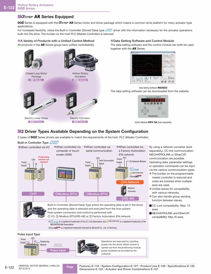
DG Series is equipped with the AR Series motor and driver package which means a common drive platform for many actuator type applications.For increased flexibility, utilize the Built-in Controller (Stored Data) type driver with the information necessary for the actuator operations built into the drive. The burden on the host PLC (Master Controller) is reduced.
●A Variety of Products with a Unified Control MethodAll products in the AR Series group have unified controllability.
Electric Linear SlidesEAS Series
Closed Loop Motor Package
AR Series
Electric CylindersEAC Series
Hollow Rotary Actuators
DG Series
●Data Setting Software and Control ModuleThe data setting software and the control module can both be used together with the AR Series.
Data Setting Software MEXE02The data setting software can be downloaded from the website.
Control Module OPX-2A (Sold separately)
■2 Driver Types Available Depending on the System Configuration
2 types of DG Series drivers are available to match the requirements of the host PLC (Master Controller).
Built-in Controller Type
● When controlled via I/O ● When controlled via computer or touch screen (HMI)
● When controlled via serial communication
● When controlled via a Factory Automation (FA) network
By using a network converter (sold separately), CC-link communication, MECHATROLINK or EtherCAT communication are possible. Operating data, parameter settings or operation commands can be input via the various communication types.
● The burden on the programmable master controller is reduced and costs are lowered when multiple axes are used. ● Unifies slaves for compatibility with various networks. ● Can also handle group sending function between slaves.
■ CC-Link compatibility: Max. 12 axes.
■ MECHATROLINK and EtherCAT compatibility: Max.16 axes.
①I/O ②Modbus (RTU)
I/O
Positioning module not
requiredCPU
Power Supply
②Modbus (RTU)
Serial Communication Module
CPU
Power Supply
②RS-485
③FA Network
Network Converter
CPUPower Supply FA Network Module
Built-in Controller (Stored Data) Type where the operating data is set in the driver,
and the operating data is selected and executed from the host system.
Host system connection and control is performed with① I/O, ② Modbus (RTU)/RS-485 or ③ Factory Automation (FA) network.
● is a registered trademark of the CC-Link Association and is a registered trademark of the MECHATROLINK Association.
● is a registered trademark licensed by Beckhoff Co., Ltd. of Germany
Pulse Input Type
Pulse Input
CPUPower Supply I/O Positioning
Module
Operations are executed by inputting pulses into the driver. Motor control is carried out from the positioning module (pulse oscillator) as provided by the customer.

E-123
Linear & Rotary Actuators E-123
Electric
Linear
Slides
Overview,
Product
Series
AREAS
AREAC
ARDG
DRL
Electric
Cylinders
Hollow
Rotary
Actuators
Accessories
CAD DataManuals
www.orientalmotor.com Technical Support
TEL: (800) 468-3982E-mail: [email protected]
■Driver Features
Built-in Controller Type
Because the driver has the information necessary for actuator operation, the burden on the host PLC is reduced. The system configuration when using multi-axis control can be simplified.Setting can be done by data setting software, a control module (sold separately), or RS-485 communication.
Operation Types
In the built-in controller type, the operating speed and traveling amount of the actuator are set with operating data, and operation is performed according to the selected operating data.
Basic Setting(Factory setting)
DriverActuator
Connection Cable
Setting Operating Data Changing Parameters Data Setting
Test Operation
Alarm History
Parameter Changing
Monitoring
Data Copy
Control Module
(OPX-2A)
or
Data Setting Software (MEXE02)
●Setting using RS-485 communication is also possible. ●The data setting software can be downloaded from the website.
Item Description
Common
Control Method
I/O Control
RS-485 CommunicationNetwork Converter Connection
Modbus RTU Protocol Connection
Position Command Input Setting with operating data number Command range for each point: −8388608∼8388607 [step] (Setting unit: 1 [step])
Speed Command Input Setting with operating data number Command range: 0∼1000000 [Hz] (Setting unit: 1 [Hz])
Acceleration/Deceleration Command Input
Set with the operating data number or parameter.The acceleration/deceleration rate [ms/kHz] or acceleration/deceleration time [s] can be selected.Command range: 0.001∼1000.000 [ms/kHz] (Setting unit: 0.001 [ms/kHz])0.001∼1000.000 [s] (Setting unit: 0.001 [s])
Acceleration/Deceleration Processing
Velocity Filter, Traveling Average Filter
Return-To-Home Operation
Return-to-Home Modes
2-Sensor Mode A return-to-home operation that uses a limit sensor (+LS, −LS).
3-Sensor Mode A return-to-home operation that uses a limit sensor and a HOME sensor.
Position PresetA function where P-PRESET is input at the desired position to confi rm the home position.
The home position can be set to the desired value.
Positioning Operation
Number of Positioning Points 64 points (No.0∼63)
Operating ModesIncremental Mode (Relative positioning)
Absolute Mode (Absolute positioning)
Operation Functions
Independent Operation A PTP (Point to Point) positioning operation.
Linked Operation A multistep speed-change positioning operation that is linked with operating data.
Linked Operation 2A positioning operation with a timer that is linked with operating data.The timer (dwell time) can be set from 0∼50.000 [s]. (Setting unit: 0.001 [s])
Start Methods
Operating Data Selection Method Starts the positioning operation when START is input after selecting M0∼M5.
Direct Method (Direct positioning)Starts the positioning operation with the operating data number set in the parameters when MS0∼MS5 is input.
Sequential Method (Sequential positioning) Starts the positioning operation in sequence from operating data No. 0 each time SSTART is input.
Continuous Operation
Number of Speed Points 64 points (No.0∼63)
Speed Change Method Changes the operating data number.
Other Operations
JOG Operation Regular feed is performed by inputting +JOG or −JOG.
Automatic Return OperationWhen the motor position is moved by an external force while the motor is in a non-excitation state, it automatically returns to the position where it originally stopped.
Control Mode✽ The normal mode and the current control mode can be selected.
Absolute Backup An absolute system can be built by using a battery (accessory).
●Push-motion operation cannot be used with this product.
✽Except when further reduction of heat generation or noise is needed, using normal mode is recommended.
Positioning Operation
● Operating Data
Selection Method ● Direct Positioning ● Sequential Positioning
<Start Methods> ● Independent Operation
Speed
TimeStart Command
Operating DataNo.0
Operating Data No.1
● Linked Operation
Speed
Time
Operating DataNo.0
Operating DataNo.1
Start Command
● Linked Operation 2
Speed
Time
Dwell Time
Operating DataNo.0
Operating DataNo.1
Start Command

E-124
E-124Hollow Rotary ActuatorsDG Series
ORIENTAL MOTOR GENERAL CATALOG 2015/2016
Page Features E-118 / System Configuration E-127 / Product Line E-129 / Specifications E-130
Dimensions E-133 / Actuator and Driver Combinations E-137
●Equipped with a sequence for return-to-home operation that reduces the burden of the host master and the hassle of creating a ladder.
● Position Preset
● JOG Operation (Test operation)
● Automatic Return Operation
● 2-Sensor Mode
−LS +LSVRVS
VSVR−Side
+Side
● 3-Sensor Mode
−LS +LSVRVS
VSVR−Side
+SideHOMES
Return-To-Home Operation Other OperationsContinuous Operation
−Direction
+DirectionMotor Operation
Time
FWD Input
RVS Input
M0∼M5 Inputs
Main Functions
Function Description
Motor Resolution Setting Function✽1
The motor resolution can be changed by the driver without the mechanically operated speed reduction mechanism.Determining the minimum traveling amount of the output table
1000 × Electronic gear B
× 18 [˚]Electronic gear A (Gear ratio)
Group Send Function(Via RS-485 communication or network converter)
Confi gure a group of multiple axes connected using RS-485 communication, and send commands by group.Simultaneous start and operation can also be performed for multiple axes.
Round Function
A function that returns the command position and multiple rotation data to 0 when the command position exceeds the round setting range parameter setting value.Since the multiple rotation data is returned to 0, position control is possible even with continuous rotation operation in the same direction using an absolute backup system.
●When building an absolute system, the accessory (sold separately) battery is necessary.
Hardware Overtravel This function stops the actuator when the mechanical limit sensor is exceeded.
Software OvertravelThis function stops the actuator when exceeding the limit set by the software.Depending on the setting, an alarm can also be output without stopping.
STOP Input(External stop)
This function forcibly stops operation when there is an abnormality or other issue. Select instantaneous stop, deceleration stop, or all windings off (actuator holding force is off) as the stopping method.
Alarm Code Output Alarm codes that are occurring can be output.
Alarm HistoryEven if the power is turned off, up to 10 alarms that have occurred can be stored.This can be used for troubleshooting.
Velocity Filter
This is used to make the movement at start/stop smoother or to reduce vibration during low-speed operation. This function controls the speed changes of the actuator to prevent them from becoming too large even for sudden operation command changes.
Teaching Function✽1 Teaching can be performed. Move the load to the target position, and store the position data for that time as the positioning data.
I/O Monitoring✽1 The ON/OFF status of the I/O signals can be checked.
Waveform Monitoring✽2 The operating speed and I/O signals can be checked as a waveform.
●The data setting software MEXE02 can be downloaded from the website. ✽1 Can be performed with the separately-sold control module (OPX-2A) or data setting software (MEXE02).
✽2 Can be performed with the data setting software (MEXE02).
0 axis Start the positioning operation
Actuator Operation for Axis No. 0 (Main)
Actuator Operation for Axis No. 1 (Sub)
Operation Command (RS-485 communication)
n
p
ry.
g
d.
n Time
Actu
ator
Spe
ed
At 1024
At 1
Difference in Characteristics Due to Velocity Filter

E-125
Linear & Rotary Actuators E-125
Electric
Linear
Slides
Overview,
Product
Series
AREAS
AREAC
ARDG
DRL
Electric
Cylinders
Hollow
Rotary
Actuators
Accessories
CAD DataManuals
www.orientalmotor.com Technical Support
TEL: (800) 468-3982E-mail: [email protected]
Pulse Input Type
Use the control module (sold separately) and data setting software to perform operations, such as changing the parameters, displaying the alarm history, and performing various types of monitoring.
Basic Setting(Factory setting)
Connection Cable
Test Operation
Alarm History
Parameter Changing
Monitoring
Data Copy
Control Module(OPX-2A)
Data Setting Software (MEXE02)
●The data setting software can be downloaded from the website.
DriverActuator
Main Functions
Item OverviewBasic
SettingExtended Settings
Selection of Pulse Input Mode
1-pulse input mode or 2-pulse input mode can be selected. ● ●
In addition to the normal settings, the phase difference input can also be set.· 1-pulse input mode (positive logic/negative logic)· 2-pulse input mode (positive logic/negative logic)· Phase difference input (1-multiplication/2-multiplication/4-multiplication)
− ●
Resolution SettingThe resolution can be selected with a function switch. ● ●
The function switch can be used to the change each of the corresponding electronic gear values. − ●
Running Current SettingThe running current setting can be changed with the current setting switch (CURRENT). ● ●
The value corresponding to each stage of the current setting switch (CURRENT), 0∼F (16 stages), can be changed. − ●
Standstill Current Ratio Setting The ratio of the standstill current relative to the running current can be set. − ●
Motor Rotational Coordinates Setting The rotational coordinates for the motor can be set. − ●
All Windings On Signal (C-ON input)The input signal for the excitation of the motor. ● ●
The logic of the C-ON input during power supply input can be set. − ●
Return to Excitation Position Operation During All Windings OnEnable/Disable
Set whether or not to return to the excitation position (deviation 0 position) during all windings on. − ●
Alarm Code Signal Enable/Disable Set to output the code when an alarm occurs. − ●
END Output Signal Range Setting The END output signal range can be changed. − ●
END Output Signal Offset The END output signal value can be offset. − ●
A/B Phase Output This can be used to confi rm the position of the motor. ● ●
Timing Output Signal This is output each time the motor rotates 7.2˚ (0.4˚ for the output table). ● ●
Velocity Filter SettingApplies a fi lter to the operation command to control the motor action. ● ●
The values corresponding to each of 0∼F (16 levels) for the setting switch. − ●
Vibration Suppression Function for Normal ModeThis can be set to suppress resonant vibration during rotation. − ●
This can be set to suppress vibration during acceleration, and deceleration, and when stopped. − ●
Gain Adjustment for Current Control Mode✽
Adjusts the position and speed loop gain. − ●
Adjusts the speed integration time constant. − ●
Sets the damping control vibration frequency. − ●
Sets whether to enable or disable damping control. − ●
Selection of Motor Excitation Position at Power On The motor excitation position for when the power is on can be selected. − ●
Control Module SettingSelect whether to use symbols or an absolute value display for the speed display of the control module. − ●
The geared motor gear ratio for the speed monitor can be set. (The gear ratio for the DG Series is 1:18) − ●
●The data setting software MEXE02 can be downloaded from the website. ✽Except when further reduction of heat generation or noise is needed, using normal mode is recommended.
Extended Settings

E-126
E-126Hollow Rotary ActuatorsDG Series
ORIENTAL MOTOR GENERAL CATALOG 2015/2016
Page Features E-118 / System Configuration E-127 / Product Line E-129 / Specifications E-130
Dimensions E-133 / Actuator and Driver Combinations E-137
How to Read Specifications
●Hollow Rotary ActuatorsFrame Size mm (in.) 60 (2.36) 85 (3.35) 130 (5.12) 200 (7.87)
Product NameBuilt-in Controller DG60-AR□KD2-3 DG85R-AR□ ■■D2-3 DG130R-AR□ ■■D2-3 DG200R-AR□ ■■D2-3Pulse Input DG60-AR□K2-3 DG85R-AR□ ■■2-3 DG130R-AR□ ■■2-3 DG200R-AR□ ■■2-3
Motor Type AR Series① Type of Output Table Supporting Bearing Deep-Groove Ball Bearing Cross-Roller Bearing
② Inertia J: kg·m2 (oz-in2)4324×10-7
(23.7)22092×10-7
(120.8)150620×10-7 [189500×10-7]
(823.9) [(1036.6)]916400×10-7 [955280×10-7]
(5012.7) [(5225.4)]
Gear Ratio 18③ Motor Resolution 1000 P/R④ Permissible Torque N·m (lb-in) 0.9 (7.9) 2.8 (24) 12 (106) 50 (440)
⑤Holding Torque at Motor Standstill
Power ON N·m (lb-in) 0.45 (3.9) 1.8 (15.9) 12 (106)36 [20]
(310) [(177)]
Electromagnetic Brake N·m (lb-in) − − 12 (106) 20 (177)⑥ Rated Speed r/min 200 110⑦ Repetitive Positioning Accuracy arcsec (degrees) ±15 (±0.004°)⑧ Lost Motion arcmin (degrees) 2 (0.033°)⑨ Angular Transmission Accuracy arcmin (degrees) 4 (0.067°) 4 (0.067°) 3 (0.05°) 2 (0.033°)⑩ Permissible Axial Load N (lb.) 100 (22) 500 (112) 2000 (450) 4000 (900)⑪ Permissible Moment Load N·m (lb-in) 2 (17.7) 10 (88) 50 (440) 100 (880)⑫ Runout of Output Table Surface mm (in.) 0.030 (0.0012) 0.015 (0.0006)⑬ Runout of Output Table Inner (Outer) Diameter mm (in.) 0.030 (0.0012) 0.015 (0.0006) 0.030 (0.0012)⑭ Parallelism of Output Table mm (in.) 0.050 (0.002) 0.030 (0.0012) 0.050 (0.002)
⑮Degree of Protection
Single Shaft, Electromagnetic Brake Type IP40 (IP20 for motor connector)Double Shaft IP20
Power Supply Input
Voltage and Frequency
Built-in Controller 24 VDC±5% Single-Phase 100-120 VAC, Single-Phase 200-240 VAC −15∼+6%, 50/60 HzPulse Input 24 VDC±10% Single-Phase 100-115 VAC, Single-Phase 200-230 VAC, Three-Phase 200-230 VAC −15∼+10%, 50/60 Hz
Input Current A
Built-in Controller
24 VDC 1.3 − − −Single-Phase 100-120 VAC − 2.4 3.6 5.9Single-Phase 200-240 VAC − 1.5 2.3 3.7
Pulse Input
24 VDC 0.9 − − −Single-Phase 100-115 VAC − 2.9 4.4 6.5Single-Phase 200-230 VAC − 1.9 2.7 4.1Three-Phase 200-230 VAC − 1.0 1.4 2.2
Control Power Supply − 24 VDC±5%, 0.5 AElectromagnetic Brake Power Supply Input − − 24 VDC±5%, 0.25 A
① Type of Output Table Supporting Bearing The type of bearing used for the output table.
② InertiaThe total sum of the rotor inertia of the motor and the inertia of the reduction mechanism, converted to a moment on the output table.
③ Motor ResolutionThe number of pulses needed to rotate the output table by one rotation. Check the operating manual for the method of calculating the minimum traveling amount [ ̊ ] of the output table at a gear ratio of 18.
④ Permissible TorqueThe limit of mechanical strength of the reduction mechanism. Make sure the applied torque, including the acceleration torque and load fluctuation, does not exceed the permissible torque.
⑤Holding Torque at Motor Standstill ● Power ON: This is the maximum torque with which to hold the output table in position if it stops when the power is on. ● Electromagnetic Brake: Static friction torque when the electromagnetic brake is activated at standstill is shown. (Electromagnetic brake is non-excitation actuated type)
⑥ Rated SpeedThe output table speed that the mechanical strength of the speed reduction mechanism can tolerate.
⑦ Repetitive Positioning AccuracyA value indicating the degree of error that generates when positioning is performed repeatedly to the same position in the same direction.
⑧ Lost MotionThe difference in stopped angles achieved when the output table is positioned to the same position in the forward and reverse directions.
⑨ Angular Transmission AccuracyThe difference between the theoretical rotation angle of the output table as calculated from the input pulse number and the actual rotation angle.
⑩ Permissible Axial LoadThe permissible value of axial load applied to the output table in the axial direction.
⑪ Permissible Moment LoadWhen a load is applied to a position away from the center of the output table, the output table receives a tilting force. The permissible moment load refers to the permissible value of moment load calculated by multiplying the offset distance from the center by the applied load.
⑫ Runout of Output Table SurfaceThe maximum value of runout of the mounting surface of the output table when the output table is rotated under no load.
⑬ Runout of Output Table Inner (Outer) DiameterThe maximum value of runout of the inner diameter or outer diameter of the table when the output table is rotated under no load.
⑭ Parallelism of Output TableAn inclination of the mounting surface of the output table compared with the actuator mounting surface on the equipment side.
⑮ Degree of ProtectionIEC 60529 and EN 60034-5 (IEC 60034-5) classify the dust resistance and waterproofing into grades.

E-127
Linear & Rotary Actuators E-127
Electric
Linear
Slides
Overview,
Product
Series
AREAS
AREAC
ARDG
DRL
Electric
Cylinders
Hollow
Rotary
Actuators
Accessories
CAD DataManuals
www.orientalmotor.com Technical Support
TEL: (800) 468-3982E-mail: [email protected]
Hollow Rotary Actuators
For Electromagnetic Brake
For Motor
The product comes with a 3 m (9.8 ft.) cable (for motor and electromagnetic brake).
AR Series Driver
Control Module
➜ Page E-150 Data Setting Software
Communication Cable
➜ Page E-150
Accessories (Sold separately)✽2
Computer✽1
To USB Port
or
Example of System Confi guration●
DG SeriesSold Separately
Mounting Pedestals Home Sensor Sets
DG130R-ARMAD2-3 MDG130B PADG-SB$2,654.00 $400.00 $107.00
● The system configuration shown above is an example. Other combinations are also available.
DG Series
Sensor✽1
Programmable
Controller✽1
Cables Used for EMC Directive Evaluation
Using an accessory connection cable.(Not using the cable included with the products.)
Using an accessory extension cable with the included 3 m (9.8 ft.) cable.
(For Motor) (For Electromagnetic Brake) (For Motor) (For Electromagnetic Brake)
Connection Cable Sets
Flexible Connection Cable Sets
AC Input ➜ Page E-141DC Input ➜ Page E-146
Extension Cable Sets
Flexible Extension Cable Sets
AC Input ➜ Page E-142DC Input ➜ Page E-147
Accessories (Sold separately)
or
Network Converters
➜ Page F-8
Peripheral Products (Sold separately)
24 VDC Power
Supply for Control✽1
Data Setting Software
MEXE02
(For RS-485 communication)
Mounting Pedestals
➜ Page E-158Battery Set
➜ Page E-151 Home Sensor Sets
➜ Page E-155RS-485 Communication
Cables
➜ Page E-145, 149
Accessories (Sold separately)
■System Configuration
●When Equipped with AR Series, Built-in Controller Type with Electromagnetic BrakeAn example of a configuration using I/O control or RS-485 communication is shown below. ✽1 Not supplied
✽2 Required for I/O control drive.
Main Power Supply

E-128
E-128Hollow Rotary ActuatorsDG Series
ORIENTAL MOTOR GENERAL CATALOG 2015/2016
Page Features E-118 / System Configuration E-127 / Product Line E-129 / Specifications E-130
Dimensions E-133 / Actuator and Driver Combinations E-137
Hollow Rotary Actuators
For Electromagnetic Brake
For Motor
The product comes with a 3 m (9.8 ft.) cable (for motor and electromagnetic brake).
AR Series Driver
Data Setting Software
MEXE02
Mounting Pedestals
➜ Page E-158 Home Sensor Sets
➜ Page E-155General-Purpose Cables
➜ Page E-143, 148Connector - Terminal Block
Conversion Units
➜ Page E-143, 148
Example of System Confi guration●
DG SeriesSold Separately
Controller Mounting Pedestals Home Sensor Sets Connector-Terminal Block Conversion Units 1 m (3.3 ft.)
DG130R-ARMA2-3 SCX11 MDG130B PADG-SB CC36T10E$2,654.00 $349.00 $400.00 $107.00 $284.00
● The system configuration shown above is an example. Other combinations are also available.
●When Equipped with AR Series, Pulse Input Type with Electromagnetic BrakeAn example of a single-axis system configuration with the SCX11 controller is shown below.
Control Module
➜ Page E-150 Data Setting Software
Communication Cable
➜ Page E-150
Accessories (Sold separately)
DG Series
Accessories (Sold separately)
Controller
➜ Page F-12
Controller (Sold separately)
To USB Port
24 VDC Power Supply✽
Programmable
Controller✽
or
or
Main Power Supply
Sensor✽
24 VDC Power Supply for
Electromagnetic Brake✽Computer
Cables Used for EMC Directive Evaluation
Using an accessory connection cable.(Not using the cable included with the products.)
Using an accessory extension cable with the included 3 m (9.8 ft.) cable.
(For Motor) (For Electromagnetic Brake) (For Motor) (For Electromagnetic Brake)
Connection Cable Sets
Flexible Connection Cable Sets
AC Input ➜ Page E-141DC Input ➜ Page E-146
Extension cable sets
Flexible extension cable sets
AC Input ➜ Page E-142DC Input ➜ Page E-147
Accessories (Sold separately)
or
✽Not supplied

E-129
Linear & Rotary Actuators E-129
Electric
Linear
Slides
Overview,
Product
Series
AREAS
AREAC
ARDG
DRL
Electric
Cylinders
Hollow
Rotary
Actuators
Accessories
CAD DataManuals
www.orientalmotor.com Technical Support
TEL: (800) 468-3982E-mail: [email protected]
■Product Number
DG 130 R - AR A C D 2 - 1 ① ② ③ ④ ⑤ ⑥ ⑦ ⑧ ⑨
① Series Name DG: DG Series
②
Frame Size 60: 60 mm (2.36 in.)85: 85 mm (3.35 in.)130: 130 mm (5.12 in.)200: 200 mm (7.87 in.)
③Type of Output Table Supporting Bearing
R: Cross-Roller BearingBlank: Deep-Groove Ball Bearing
④ Motor Type AR: AR Series
⑤Motor Shaft A: Single Shaft
B: Double ShaftM: With Electromagnetic Brake
⑥
Power Supply Input AR Series (Built-in controller type)A: Single-Phase 100-120 VACC: Single-Phase 200-240 VACK: 24 VDC
AR Series (Pulse input type)A: Single-Phase 100-115 VACC: Single-Phase 200-230 VACS: Three-Phase 200-230 VACK: 24 VDC
⑦ Driver Type D: Built-in Controller TypeBlank: Pulse Input Type
⑧ Reference Number −
⑨ Connection Cable✽ Number: Length of Included Connection Cable 3: 3 m (9.8 ft.)
✽Connection cables 5 m (16.4 ft.) and longer are available as accessories (sold separately).
●Either A (single-phase 100-115 (120) VAC), C (single-phase 200-230 (240) VAC) or S (three-phase 200-230 VAC: pulse input packages only) indicating power supply input is entered where the ■■ is located within the product name.
■Product Line
●Built-in Controller Type ◇AC Input
Product Name List PriceDG85R-ARA ■■D2-3 $2,183.00DG85R-ARB ■■D2-3 $2,186.00DG130R-ARA ■■D2-3 $2,410.00DG130R-ARB ■■D2-3 $2,413.00DG130R-ARM ■■D2-3 $2,654.00DG200R-ARA ■■D2-3 $2,841.00DG200R-ARB ■■D2-3 $2,845.00DG200R-ARM ■■D2-3 $3,085.00
◇DC InputProduct Name List Price
DG60-ARAKD2-3 $1,315.00DG60-ARBKD2-3 $1,318.00
●Pulse Input Type ◇AC Input
Product Name List PriceDG85R-ARA ■■2-3 $2,183.00DG85R-ARB ■■2-3 $2,186.00DG130R-ARA ■■2-3 $2,410.00DG130R-ARB ■■2-3 $2,413.00DG130R-ARM ■■2-3 $2,654.00DG200R-ARA ■■2-3 $2,841.00DG200R-ARB ■■2-3 $2,845.00DG200R-ARM ■■2-3 $3,085.00
The following items are included with each product.
Actuator, Driver, Cable for Motor✽1, Cable for Electromagnetic Brake✽1✽2, Connector Set for Driver, Operating Manual✽3
✽1 Accessory cables (sold separately) must be purchased in the following situations:· When using a flexible extension cable· When using a cable longer than 3 m (9.8 ft.)
✽2 Only for electromagnetic brake type.
✽3 Details regarding product installation and wiring are in the operating manual. See the user manual for details regarding product operation.
◇DC InputProduct Name List Price
DG60-ARAK2-3 $1,265.00DG60-ARBK2-3 $1,268.00

E-130
E-130Hollow Rotary ActuatorsDG Series
ORIENTAL MOTOR GENERAL CATALOG 2015/2016
Page Features E-118 / System Configuration E-127 / Product Line E-129 / Specifications E-130
Dimensions E-133 / Actuator and Driver Combinations E-137
■Specifications
● Hollow Rotary Actuators AC input: ✽1 ✽1 ✽2 ✽1 DC input: ✽1
Frame Size mm (in.) 60 (2.36) 85 (3.35) 130 (5.12) 200 (7.87)
Product NameBuilt-in Controller DG60-AR□KD2-3 DG85R-AR□ ■■D2-3 DG130R-AR□ ■■D2-3 DG200R-AR□ ■■D2-3Pulse Input DG60-AR□K2-3 DG85R-AR□ ■■2-3 DG130R-AR□ ■■2-3 DG200R-AR□ ■■2-3
Motor Type AR SeriesType of Output Table Supporting Bearing Deep-Groove Ball Bearing Cross-Roller Bearing
Inertia J: kg·m2 (oz-in2)4324×10-7
(23.7)22092×10-7
(120.8)150620×10-7 [189500×10-7]✽3
(823.9) [(1036.6)]✽3916400×10-7 [955280×10-7]✽3
(5012.7) [(5225.4)]✽3
Gear Ratio 18Motor Resolution✽4 1000 P/RPermissible Torque N·m (lb-in) 0.9 (7.9) 2.8 (24) 12 (106) 50 (440)
Holding Torque at Motor Standstill
Power ON N·m (lb-in) 0.45 (3.9) 1.8 (15.9) 12 (106)36 [20]✽3
(310) [(177)]✽3
Electromagnetic Brake N·m (lb-in) − − 12 (106) 20 (177)Rated Speed r/min 200 110Repetitive Positioning Accuracy arcsec (degrees) ±15 (±0.004°)Lost Motion arcmin (degrees) 2 (0.033°)Angular Transmission Accuracy arcmin (degrees) 4 (0.067°) 4 (0.067°) 3 (0.05°) 2 (0.033°)Permissible Axial Load N (lb.) 100 (22) 500 (112) 2000 (450) 4000 (900)Permissible Moment Load N·m (lb-in) 2 (17.7) 10 (88) 50 (440) 100 (880)Runout of Output Table Surface mm (in.) 0.030 (0.0012) 0.015 (0.0006)Runout of Output Table Inner (Outer) Diameter mm (in.) 0.030 (0.0012) 0.015 (0.0006) 0.030 (0.0012)Parallelism of Output Table mm (in.) 0.050 (0.002) 0.030 (0.0012) 0.050 (0.002)
Degree of ProtectionSingle Shaft, Electromagnetic Brake Type IP40 (IP20 for motor connector)Double Shaft IP20
Power Supply Input
Voltage and Frequency
Built-in Controller 24 VDC±5% Single-Phase 100-120 VAC, Single-Phase 200-240 VAC −15∼+6%, 50/60 HzPulse Input 24 VDC±10% Single-Phase 100-115 VAC, Single-Phase 200-230 VAC, Three-Phase 200-230 VAC −15∼+10%, 50/60 Hz
Input Current A
Built-in Controller
24 VDC 1.3 − − −Single-Phase 100-120 VAC − 2.4 3.6 5.9Single-Phase 200-240 VAC − 1.5 2.3 3.7
Pulse Input
24 VDC 0.9 − − −Single-Phase 100-115 VAC − 2.9 4.4 6.5Single-Phase 200-230 VAC − 1.9 2.7 4.1Three-Phase 200-230 VAC − 1.0 1.4 2.2
Control Power Supply − 24 VDC±5%, 0.5 AElectromagnetic Brake Power Supply Input✽5 − − 24 VDC±5%✽6, 0.25 A
●Either A (single shaft), B (double shaft) or M (with electromagnetic brake) indicating the configuration of the motor is entered where the box □ is located within the product name. For DG60 and DG85R, either A (single shaft) or B (double shaft) is entered. ●Either A (single-phase 100-115 (120) VAC), C (single-phase 200-230 (240) VAC) or S (three-phase 200-230 VAC: pulse input packages only) indicating power supply input is entered where the box ■■ is located within the product name.
✽1 For motor product names, not actuator product names. (DG200R-ARM ■ ■ 2-3: CE Marking only)
✽2 Pulse input type only (excluding DG200R-ARM ■ ■ 2-3)
✽3 The brackets [ ] indicate the specifications for the electromagnetic brake type.
✽4 The motor resolution when shipped. Check the operating manual for the method of calculating the minimum traveling amount [ ̊ ] of the output table at a gear ratio of 18.
✽5 For the pulse input type, a separate power supply for the electromagnetic brakes is required for the electromagnetic brake type.
✽6 If the wiring distance between the motor and driver is extended to 20 m (65.6 ft.) or longer using an accessory cable (sold separately), the 24 VDC±4% specification applies.Note
●The back shaft on a double shaft motor is intended for installation of a slit disk. Do not apply load torque, radial load or axial load to the back shaft of the motor. ●Depending on the driving conditions, a considerable amount of heat may be generated by the motor. Be sure to keep the motor case temperature at 100˚C (212˚F) or less. ●The repetitive positioning accuracy is measured at a constant temperature (normal temperature) under a constant load.
●General Specifications (Actuator)Motor Type AR Series AC Input AR Series DC Input
Thermal Class 130 (B) [The DC input is certifi ed as compliant with UL Standards 105 (A).]
Insulation ResistanceThe measured value is 100 MΩ or more when a 500 VDC megger is applied between the following locations: · Between the case and motor sensor windings· Between the case and electromagnetic brake windings
Dielectric StrengthSuffi cient to withstand the following for 1 minute: · Between the case and motor sensor windings: 1.5 kVAC, 50 Hz or 60 Hz· Between the case and electromagnetic brake windings: 1.5 kVAC, 50 Hz or 60 Hz
Suffi cient to withstand the following for 1 minute: · Between the case and motor sensor windings: 0.5 kVAC, 50 Hz or 60 Hz
Operating Environment (In operation)
Ambient Temperature
0∼+50°C (+32∼+122°F) (Non-freezing)When home sensor set (accessory) is installed: 0∼+40°C (+32∼+104°F) (Non-freezing)
Ambient Humidity 85% or less (non-condensing)Atmosphere Use in an area without corrosive gases and dust. The product should not be exposed to water, oil or other liquids.
Note ●Do not perform the insulation resistance test or dielectric voltage withstand test while the actuator and driver are connected.
●Driver SpecificationsAR Series AC Input ➜ Page A-44 DC Input ➜ Page A-165

E-131
Linear & Rotary Actuators E-131
Electric
Linear
Slides
Overview,
Product
Series
AREAS
AREAC
ARDG
DRL
Electric
Cylinders
Hollow
Rotary
Actuators
Accessories
CAD DataManuals
www.orientalmotor.com Technical Support
TEL: (800) 468-3982E-mail: [email protected]
■Load Inertia – Positioning Time (Reference value)
DG60
050 100 150 200 300250
0.7
0.6
0.8
0.5
0.4
0.3
0.2
0.1
Load Inertia✽ JL [×10–4 kg·m2]
0 500 1000 1500Load Inertia✽ JL [oz-in2]
Posi
tioni
ng T
ime
[ s]
0
180˚
90˚
60˚45˚30˚
15˚
DG85R
0400200 600 800 1000 14001200
0.8
0.6
1.0
0.4
0.2
0 2000 4000 6000Load Inertia✽ JL [oz-in2]
Load Inertia✽ JL [×10–4 kg·m2]
Posi
tioni
ng T
ime
[ s]
0
180˚
90˚
60˚45˚30˚
15˚
■Speed – Torque Characteristics
DG60
0.2
0.4
0.6
0.8
1.0
1.2
0 50 100 150 200 250
0 10 20 30 40 50 60 70
2
0
4
6
8
10
Speed [r/min]
Pulse Speed [kHz] (Resolution setting: 18000 P/R [1000] [×1])
Torq
ue [ N
·m]
Torq
ue [ l
b-in
]
0
Permissible Torque
DG85R
1.0
0.5
1.5
2.0
2.5
3.0
3.5
050 100 150 200 250
0 10 20 30 40 50 60 70
10
5
0
15
20
25
30
Speed [r/min]
Pulse Speed [kHz] (Resolution setting: 18000 P/R [1000] [×1])
Torq
ue [ N
·m]
Torq
ue [ l
b-in
]
0
Permissible Torque
DG130R
6
4
2
8
10
12
14
16
050 100 150 200 250
0 10 20 30 40 50 60 70
60
40
20
0
80
100
120
140
Speed [r/min]
Pulse Speed [kHz] (Resolution setting: 18000 P/R [1000] [×1])
Torq
ue [ N
·m]
Torq
ue [ l
b-in
]
0
Permissible Torque
DG200R
10
20
30
40
50
60
0 20 40 60 80 100 120
0 5 10 15 20 25 30 35
100
0
200
300
400
500
Speed [r/min]
Pulse Speed [kHz] (Resolution setting: 18000 P/R [1000] [×1])
Torq
ue [ N
·m]
Torq
ue [ l
b-in
]
0
Permissible Torque
DG130R
02000 4000 6000 8000
1.0
0.8
1.2
0.6
0.4
0.2
180˚
90˚
60˚45˚30˚
15˚
0 10000 20000 30000 40000Load Inertia✽ JL [oz-in2]
Load Inertia✽ JL [×10–4 kg·m2]
Posi
tioni
ng T
ime
[ s]
0
180˚
90˚
60˚45˚30˚
15˚
DG200R
020000 6000040000
1.4
1.2
1.0
0.8
1.6
0.6
0.4
0.2
0 100000 200000 300000Load Inertia✽ JL [oz-in2]
Load Inertia✽ JL [×10–4 kg·m2]
Posi
tioni
ng T
ime
[ s]
0
180˚
90˚
60˚45˚30˚
15˚
✽ The load inertia refers to the inertia of the customer's load.

E-132
E-132Hollow Rotary ActuatorsDG Series
ORIENTAL MOTOR GENERAL CATALOG 2015/2016
Page Features E-118 / System Configuration E-127 / Product Line E-129 / Specifications E-130
Dimensions E-133 / Actuator and Driver Combinations E-137
■Table Precision (at no load) Unit = mm (in.)
DG60
0.03(0.0012)
0.03(0.0012)A
A0.05(0.002)
A0.05
(0.002)
✽2
✽1
✽1 Runout of output table surface✽2 Runout of output table inner diameter (hollow diameter)✽3 Parallelism of output table (against the mounting surface)
✽3
✽3
DG85R, DG130R, DG200R
0.015(0.0006)
0.015(0.0006)A
A0.03
(0.0012)
A0.05
(0.002)
0.015(0.0006)
0.030(0.0012)
✽2 ✽1
✽1 Runout of output table surface✽2 Runout of output table inner and outer diameter✽3 Parallelism of output table (against the mounting surface)
✽3
✽3
ParallelismDG85R, DG130R :
DG200R :
✽2
✽2
DG85R, DG130R :
DG200R :
■Displacement by Moment Load (Reference value)
The output table will be displaced when it receives the moment load.The graph plots the table displacement that occurs at distance L from the rotation center of the output table when a given load is applied in the negative direction.The displacement becomes approximately double when the moment load is applied in both the positive and negative directions.
Moment Load [N·m] = 0.001×F×L
Distance from Center of Rotation L [mm]
Arm
F [ N
]
Disp
lace
men
t [μ
m]
DG60
00.5 2.01.51.0
140
120
100
80
60
40
201
2
0
3
4
5
0 5 1510
Moment Load [N·m]
Moment Load [lb-in]
Disp
lace
men
t [μ
m]
Disp
lace
men
t [×
10-3
in.]
0
L=100 mm (3.94 in.)
L=75 mm (2.95 in.)
L=50 mm (1.97 in.)
DG85R
02 4 6 12108
80
70
60
50
40
30
20
10
Moment Load [N·m]
Disp
lace
men
t [μ
m]
0 20 80 1006040Moment Load [lb-in]
Disp
lace
men
t [×
10-3
in.]
1
0
2
3
0
L=200 mm (7.87 in.)
L=150 mm (5.91 in.)
L=100 mm (3.94 in.)
DG130R
0 10 20 30 605040
160
140
120
100
80
60
40
20
Disp
lace
men
t [μ
m]
Disp
lace
men
t [×
10-3
in.]
2
0
4
6
Moment Load [N·m]
0 400 500100 300200Moment Load [lb-in]
0
L=400 mm (15.7 in.)
L=300 mm (11.81 in.)
L=200 mm (7.87 in.)
DG200R
020 40 60 12010080
160
140
120
100
80
60
40
20
Moment Load [N·m]
Disp
lace
men
t [μ
m]
0 200 800 1000600400Moment Load [lb-in]
Disp
lace
men
t [×
10-3
in.]
2
0
4
6
0
L=600 mm (23.62 in.)
L=400 mm (15.75 in.)
L=300 mm (11.81 in.)
L=500 mm (19.69 in.)

E-133
Linear & Rotary Actuators E-133
Electric
Linear
Slides
Overview,
Product
Series
AREAS
AREAC
ARDG
DRL
Electric
Cylinders
Hollow
Rotary
Actuators
Accessories
CAD DataManuals
www.orientalmotor.com Technical Support
TEL: (800) 468-3982E-mail: [email protected]
Product Name Actuator Product Name Mass kg (lb.) 2D CAD
DG85R-ARAA ■ ■ 2-3DGM85R-ARAC
1.2(2.6)
D2854
DG85R-ARAC ■ ■ 2-3DG85R-ARAS 2-3DG85R-ARBA ■ ■ 2-3
DGM85R-ARBCDG85R-ARBC ■ ■ 2-3DG85R-ARBS2-3
Motor Cable ϕ8 (ϕ0.31)
4×ϕ6.5 (ϕ0.26) Thru
2×M2.5✽
×4 (0.16) Deep
6×M4×8 (0.31) Deep(at equal intervals of 60°)
FixedPart
Connector Cover
ProtectiveEarth Terminal M4 14
(0.55)
29.4
( 1.1
6)
ϕ91 (ϕ3
.58)
14 ( 0.55
)
51( 2
.01)
62.5±0.03(2.4606±0.0012)
114.
4±2 (
4.50
±0.
08)
42(1.65)
85 ( 3
.35)
70±
0.5
( 2.7
6±0.
02)
58±
0.1
( 2.2
83±
0.00
4)
70±0.5(2.76±0.02)78±0.1 (3.071±0.004)
85 (3.35)
35.5±0.3 (1.398±0.012)10.5 (0.41) 13 (0.51)
7.5 (0.30)
3 (0.12)
15±1(0.59±0.04)
103.5 (4.07)
30˚
97.2±0.03
(3.8268±0.0012)13 ( 0
.51)
37.9
( 1.4
9)
400 (16)28.5 (1.12)
27(1.06)
□42
( □1.
65)
5(0.20)
17.6 (0.69)
34.5
( 1.3
6)
ϕ33
(ϕ1.
30)
ϕ5−
0.01
2
( ϕ0.
1969
−0.
0005
)0
0
5557-10R-210 (Molex)
2×ϕ5 0 (ϕ0.1969 0 )×6 (0.24) Deep
+0.0005+0.0122×ϕ5 0 (ϕ0.1969 0 ) Thru
+0.0005+0.012
+0.
0012
ϕ 52
0
( ϕ 2.0
472
0
)
+0.0
30
ϕ70
−0.
030
( ϕ2.
7559
−0.
0012
)0
0
ϕ62.5±0.1 (ϕ2.461±0.04)
2×M2.5✽×4 (0.16) Deep
RotatingPart
■Dimensions Unit = mm (in.)
●Actuator Product Name Actuator Product Name Mass kg (lb.) 2D CAD
DG60-ARAK ■ ■ 2-3 DGM60-ARAK 0.5(1.1)
D2853DG60-ARBK ■ ■ 2-3 DGM60-ARBK
Motor Leads
RotatingPart
( Holl
ow sh
aft)
43025-1000 (Molex)
11±1 (0.43±0.04) 76 (2.99)
150 (6)
31±0.3 (1.220±0.012)10 (0.39)
22.5(0.89)
2 (0.08)
ϕ4−
0.01
2
( ϕ0.
1575
−0.
0005
)0
0□
28( □
1.10
)5.
5( 0
.22)
5 (0.20) [ϕ65 (ϕ2.56)]
ϕ45
(ϕ1.
77)
ϕ 28
0+
0.021
( ϕ 1.10
24
0
)
+ 0.00
08
28.5
( 1.1
2)
60 (2.36)
60 ( 2
.36)
28 (1.10)
20.6(0.81)
78±
1
( 3.0
7±0.
04)
50±0.2 (1.969±0.008)36±0.03
(1.4173±0.0012)ϕ65−0.030 (ϕ2.5591−0.0012)00
2×ϕ5 0 (ϕ0.1969 0 ) Thru+0.0005+0.012
2×ϕ5 0 (ϕ0.1969 0 )×6 (0.24) Deep
+0.0005+0.012
2×ϕ4.5 (ϕ0.18) Thruϕ38±0.1 (ϕ1.496±0.004)
50±0.2
( 1.969
± 0.00
8)
35( 1
.38)
23(0.91)
18( 0
.71)
30°
2×M2.5✽×4 (0.16) Deep
6×M3×8 (0.31) Deep(at equal intervals of 60°)
70.71±0.03
(2.7839±0.0012)
✽ Use M2.5 screw holes when installing the home-sensor set (sold separately). Do not use these holes for any purpose other than to install the home-sensor.
✽ Use M2.5 screw holes when installing the home-sensor set (sold separately). Do not use these holes for any purpose other than to install the home-sensor.
●A letter D indicating the driver type (built-in controller type) is entered where the box ■■ is located within the product name. A code for the pulse input type is not entered in the box ■■. ●These dimensions are for the double shaft types. For the single shaft types, ignore the purple ( ) areas. ●The shaded areas are rotating parts.

E-134
E-134Hollow Rotary ActuatorsDG Series
ORIENTAL MOTOR GENERAL CATALOG 2015/2016
Page Features E-118 / System Configuration E-127 / Product Line E-129 / Specifications E-130
Dimensions E-133 / Actuator and Driver Combinations E-137
Product Name Actuator Product Name Mass kg (lb.) 2D CAD
DG130R-ARAA ■ ■ 2-3DGM130R-ARAC
2.7(5.9)
D2855
DG130R-ARAC ■ ■ 2-3DG130R-ARAS2-3DG130R-ARBA ■ ■ 2-3
DGM130R-ARBCDG130R-ARBC ■ ■ 2-3DG130R-ARBS2-3
2×M2.5✽×4 (0.16) Deep
6×M5×8 (0.31) Deep(at equal intervals of 60°)
Motor Cable ϕ8 (ϕ0.31)
2×M2.5✽×4 (0.16) Deep
Fixed Part
Protective Earth Terminal M4
Connector Cover
37±0.3 (1.457±0.012)12 (0.47) 15 (0.59)
104±0.03 (4.0945±0.0012)
120±0.1 (4.724±0.04)130 (5.12)
130
( 5.1
2)
30˚
101.5 (4.00)
90±
0.1 (
3.54
3±0.
04)
60 (2.36)
150±0.03
(5.9055±0.0012)
3 (0.12)
14 (0.55)
14 ( 0.55
)
170.
7±2 (
6.72
±0.
08)
40.7
( 1.6
0)
110±0.5 (4.33±0.02)
110±
0.5 (
4.33
±0.
02)
73.5
( 2.8
9)
7.5 (0.30)
21±1
(0.83±0.04)
13 ( 0
.51)
62.7
( 2.4
7)
28.5 (1.12)
27 (1.06)
400 (16)
5557-10R-210 (Molex)
□60
( □2.
36)
17.6 (0.69)
34.5
( 1.3
6) 5 (0.20)
2×ϕ5 0 (ϕ0.1969 0 ) Thru+0.0005+0.012
ϕ62
(ϕ2.
44)
ϕ92
0
( ϕ3.
6220
0
)
+0.
035
+0.
0014
ϕ11
4 −0.
035
( ϕ4.
4882
−0.
0014
)
0
0
ϕ8 −
0.01
5 (ϕ
0.31
50−
0.00
06)
00
ϕ141 (ϕ5.55)ϕ104±0.1 (ϕ4.094±0.004)
RotatingPart
4×ϕ9 (ϕ0.35) Thru
2×ϕ5 0 (ϕ0.1969 0 )×6 (0.24) Deep
+0.0005+0.012
Product Name Actuator Product Name Mass kg (lb.) 2D CAD
DG130R-ARMA ■ ■ 2-3DGM130R-ARMC 3
(6.6)D2856DG130R-ARMC ■ ■ 2-3
DG130R-ARMS2-3
2×M2.5✽×4 (0.16) Deep
Protective Earth Terminal M4
Motor Cable ϕ8 (ϕ0.31)
Electro MagneticBrake Cable ϕ6 (ϕ0.24)
Connector CoverConnector Cover
13 ( 0
.51)
3 (0.12)
136.5 (5.37)37±0.3 (1.457±0.012)
7.5 (0.30)15 (0.59)
28.5 (1.12)
400 (16)
12 (0.47)
62.7
( 2.4
7)□
60 ( □
2.36
)
5557-10R-210 (Molex)
14 ( 0.55
)
400
( 16)
18.5 (0.73)
16 ( 0
.63)
17.6 (0.69)
34.5
( 1.3
6)
5557-02R-210 (Molex)
ϕ62
(ϕ2.
44)
ϕ92
0
( ϕ3.
6220
0
)
+0.
035
+0.
0014
ϕ11
4 −0.
035
( ϕ4.
4882
−0.
0014
)
0
0
2×M2.5✽×4 (0.16) Deep
6×M5×8 (0.31) Deep(at equal intervals of 60°)
Fixed Part
104±0.03 (4.0945±0.0012)
120±0.1 (4.724±0.04)130 (5.12)
130
( 5.1
2)
30˚
90±
0.1 (
3.54
3±0.
04)
60 (2.36)
150±0.03
(5.9055±0.0012)
14 (0.55)
170.
7±2 (
6.72
±0.
08)
40.7
( 1.6
0)
110±0.5 (4.33±0.02)
110±
0.5 (
4.33
±0.
02)
73.5
( 2.8
9)
27 (1.06)5 (0.20)
2×ϕ5 0 (ϕ0.1969 0 ) Thru+0.0005+0.012
RotatingPart
4×ϕ9 (ϕ0.35) Thru
2×ϕ5 0 (ϕ0.1969 0 )×6 (0.24) Deep
+0.0005+0.012
ϕ141 (ϕ5.55)ϕ104±0.1 (ϕ4.094±0.004)
12 (0.47)
✽ Use M2.5 screw holes when installing the home-sensor set (sold separately). Do not use these holes for any purpose other than to install the home sensor.
●A letter D indicating the driver type (built-in controller type) is entered where the box ■■ is located within the product name. A code for the pulse input type is not entered in the box ■■. ●These dimensions are for the double shaft types. For the single shaft types, ignore the purple ( ) areas. ●The shaded areas are rotating parts.
✽ Use M2.5 screw holes when installing the home-sensor set (sold separately). Do not use these holes for any purpose other than to install the home sensor.

E-135
Linear & Rotary Actuators E-135
Electric
Linear
Slides
Overview,
Product
Series
AREAS
AREAC
ARDG
DRL
Electric
Cylinders
Hollow
Rotary
Actuators
Accessories
CAD DataManuals
www.orientalmotor.com Technical Support
TEL: (800) 468-3982E-mail: [email protected]
Product Name Actuator Product Name Mass kg (lb.) 2D CAD
DG200R-ARAA ■ ■ 2-3DGM200R-ARAC
9.4(20.7)
D2857
DG200R-ARAC ■ ■ 2-3DG200R-ARAS2-3DG200R-ARBA ■ ■ 2-3
DGM200R-ARBCDG200R-ARBC ■ ■ 2-3DG200R-ARBS2-3
2×M2.5✽×4 (0.16) Deep
Motor Cable ϕ8 (ϕ0.31)
ProtectiveEarth Terminal M4
4×ϕ11 (ϕ0.43) Thru
2×M2.5✽×4 (0.16) Deep
6×M6×10 (0.39) Deep(at equal intervals of 60°)
Connector Cover
8
0
( 0
.315
0
0
)
×8
( 0.3
1) D
eep+
0.00
06+
0.01
5
ϕ8 0 (ϕ0.3150 0 )×8 (0.31) Deep
+0.0006+0.015 10 (0.39)
65 (2.56)65±0.03
(2.559±0.0012)
173.5 (6.83)
27 (1.06)
13( 0
.51) 28.5 (1.12)
400 (16)
3.5 (0.14)
□85
( □3.
35)
250.
5±2 (
9.86
±0.
08)
200
( 7.8
7)
50.5
( 1.9
9)
101
( 3.9
8)30˚
ϕ10
0.5
( ϕ3.
96)
20 (0.79)
200 (7.87)
14( 0
.55)
85 (3.35)
14 (0.55)
98.5
( 3.8
8)
ϕ8−
0.01
5 (ϕ
0.31
5−0.
0006
)0
64±0.3(2.520±0.012)
ϕ10
0 0
( ϕ3.
9370
0
)+
0.05
4
ϕ14
0
0
( ϕ
5.51
18
0
)+
0.04
0
ϕ17
0−0.
040 (
ϕ6.
6929
−0.
0016
)0
5557-10R-210 (Molex)
ϕ155±0.2 (ϕ6.102±0.008)155±0.03 (6.1024±0.0012)
170±0.5 (6.69±0.02)
170±
0.5 (
6.69
±0.
02)
ϕ214 (ϕ8.43)
17.6 (0.69)
34.5
( 1.3
6) 5 (0.20)
0
22 (0.87)15 (0.59)8.5 (0.33)
21±1(0.83±0.04)
+0.
0016
+0.
0021
0
2×ϕ8 0 (ϕ0.3150 0 )×8 (0.31) Deep
+0.0006+0.015
RotatingPart
Fixed Part
95 ( 3
.74)
Product Name Actuator Product Name Mass kg (lb.) 2D CAD
DG200R-ARMA ■ ■ 2-3DGM200R-ARMC 10
(22)D2858DG200R-ARMC ■ ■ 2-3
DG200R-ARMS2-3
2×M2.5✽×4 (0.16) Deep
Motor Cableϕ8 (ϕ0.31)
ProtectiveEarth Terminal M4
Connector Cover
215.5 (8.48)
13( 0
.51) 28.5 (1.12)
400 (16)
3.5 (0.14)
□85
( □3.
35)
ϕ10
0.5
( ϕ3.
96)
20 (0.79)
14( 0
.55)
64±0.3(2.520±0.012)
ϕ10
0 0
( ϕ3.
9370
0
)+
0.05
4
ϕ14
0
0
( ϕ
5.51
18
0
)+
0.04
0
ϕ17
0−0.
040 (
ϕ6.
6929
−0.
0016
)0
5557-10R-210 (Molex)
17.6 (0.69)
34.5
( 1.3
6)
22 (0.87)15 (0.59)8.5 (0.33)
+0.
0016
+0.
0021
0
95 ( 3
.74)
Electro Magnetic BrakeCable ϕ6 (ϕ0.24)Connector Cover
400
( 16)
18.5 (0.73)
16 ( 0
.63)
5557-02R-210 (Molex)
12 (0.47)
4×ϕ11 (ϕ0.43) Thru
2×M2.5✽×4 (0.16) Deep
6×M6×10 (0.39) Deep(at equal intervals of 60°)
27 (1.06)
200
( 7.8
7)
50.5
( 1.9
9)
101
( 3.9
8)30˚
200 (7.87)
85 (3.35)
14 (0.55)
98.5
( 3.8
8)
ϕ155±0.2 (ϕ6.102±0.008)
155±0.03 (6.1024±0.0012)170±0.5 (6.69±0.02)
170±
0.5 (
6.69
±0.
02)
ϕ214 (ϕ8.43)
5 (0.20)
2×ϕ8 0 (ϕ0.3150 0 )×8 (0.31) Deep
+0.0006+0.015
RotatingPart
Fixed Part
8
0
( 0
.315
0
0
)
×8
( 0.3
1) D
eep+
0.00
06+
0.01
5
ϕ8 0 (ϕ0.3150 0 )×8 (0.31) Deep
+0.0006+0.015 10 (0.39)
65 (2.56)65±0.03
(2.559±0.0012)
250.
5±2 (
9.86
±0.
08)
✽ Use M2.5 screw holes when installing the home-sensor set (sold separately). Do not use these holes for any purpose other than to install the home sensor.
✽ Use M2.5 screw holes when installing the home-sensor set (sold separately). Do not use these holes for any purpose other than to install the home sensor.
●A letter D indicating the driver type (built-in controller type) is entered where the box ■■ is located within the product name. A code for the pulse input type is not entered in the box ■■. ●These dimensions are for the double shaft types. For the single shaft types, ignore the purple ( ) areas. ●The shaded areas are rotating parts.

E-136
E-136Hollow Rotary ActuatorsDG Series
ORIENTAL MOTOR GENERAL CATALOG 2015/2016
Page Features E-118 / System Configuration E-127 / Product Line E-129 / Specifications E-130
Dimensions E-133 / Actuator and Driver Combinations E-137
●Cables for Motor (Included), Cables for Electromagnetic Brake (Included) ◇AC Input, Common to All Types
●Cables for MotorCable Type Length L m (ft.)
Cable for Motor 3 (9.8)
●Cables for Electromagnetic Brake (Electromagnetic brake type only)Cable Type Length L m (ft.)
Cable for Electromagnetic Brake 3 (9.8)
◇DC Input, Common to All Types ●Cables for Motor
Cable Type Length L m (ft.)Cable for Motor 3 (9.8)
●Driver DimensionsAR Series AC Input ➜ A-61 DC Input ➜ A-185
■Connection and Operation
AR Series AC Input Built-in Controller Type ➜ A-62 Pulse Input Type ➜ A-67AR Series DC Input Built-in Controller Type ➜ A-186 Pulse Input Type ➜ A-190
5557-10R-210(Molex)
12 (0.47)
22.2
( 0.8
7)
14.5 (0.57)
37.5
( 1.4
8)
11.6 (0.46)19.6(0.77)
20.6 (0.81)
Motor Side Driver Side
30 ( 1
.18)
24.3
( 0.9
6)
23.9 (0.94)ϕ8 (ϕ0.31)
L
75 (2.95)
5559-10P-210(Molex) Connector Cover
13.5 (0.53)
19(0.75)
11.8
( 0.4
6) 80±10(3.15±0.39)24
(0.94) L
ϕ4.1 (ϕ0.16)
Driver SideMotor Side
Stick Terminal : AI0.5-8WH(PHOENIX CONTACT)
Connector Cover
76 (2.99)
21.5
( 0.8
5)
5559-02P-210(Molex)
ϕ8 (ϕ0.31)
43020-1000 (Molex) 43025-1000 (Molex)
15.9
(0.6
3)
10.9 (0.43)8.3 (0.33)7.9 (0.31)
22.3
(0.8
8)16
.5 (0
.65)
L14 (0.55)16.9 (0.67)
Motor Side Driver Side
E-137
Linear & Rotary Actuators E-137
Electric
Linear
Slides
Overview,
Product
Series
AREAS
AREAC
ARDG
DRL
Electric
Cylinders
Hollow
Rotary
Actuators
Accessories
CAD DataManuals
www.orientalmotor.com Technical Support
TEL: (800) 468-3982E-mail: [email protected]
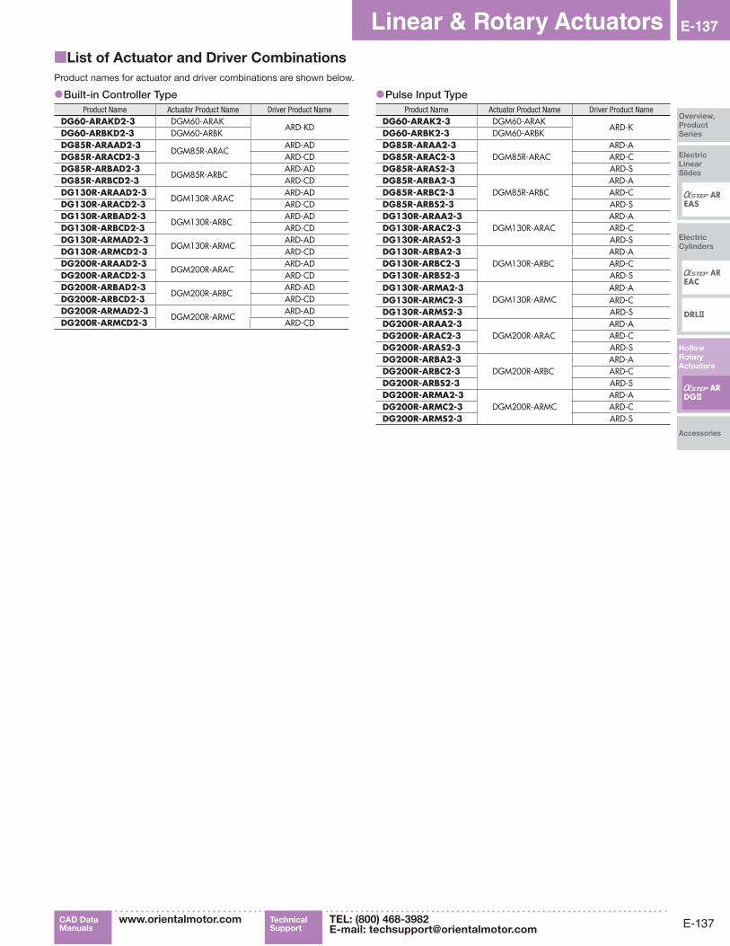
■List of Actuator and Driver Combinations
Product names for actuator and driver combinations are shown below.
●Built-in Controller TypeProduct Name Actuator Product Name Driver Product Name
DG60-ARAKD2-3 DGM60-ARAKARD-KD
DG60-ARBKD2-3 DGM60-ARBKDG85R-ARAAD2-3
DGM85R-ARACARD-AD
DG85R-ARACD2-3 ARD-CDDG85R-ARBAD2-3
DGM85R-ARBCARD-AD
DG85R-ARBCD2-3 ARD-CDDG130R-ARAAD2-3
DGM130R-ARACARD-AD
DG130R-ARACD2-3 ARD-CDDG130R-ARBAD2-3
DGM130R-ARBCARD-AD
DG130R-ARBCD2-3 ARD-CDDG130R-ARMAD2-3
DGM130R-ARMCARD-AD
DG130R-ARMCD2-3 ARD-CDDG200R-ARAAD2-3
DGM200R-ARACARD-AD
DG200R-ARACD2-3 ARD-CDDG200R-ARBAD2-3
DGM200R-ARBCARD-AD
DG200R-ARBCD2-3 ARD-CDDG200R-ARMAD2-3
DGM200R-ARMCARD-AD
DG200R-ARMCD2-3 ARD-CD
●Pulse Input TypeProduct Name Actuator Product Name Driver Product Name
DG60-ARAK2-3 DGM60-ARAKARD-K
DG60-ARBK2-3 DGM60-ARBKDG85R-ARAA2-3
DGM85R-ARACARD-A
DG85R-ARAC2-3 ARD-CDG85R-ARAS2-3 ARD-SDG85R-ARBA2-3
DGM85R-ARBCARD-A
DG85R-ARBC2-3 ARD-CDG85R-ARBS2-3 ARD-SDG130R-ARAA2-3
DGM130R-ARACARD-A
DG130R-ARAC2-3 ARD-CDG130R-ARAS2-3 ARD-SDG130R-ARBA2-3
DGM130R-ARBCARD-A
DG130R-ARBC2-3 ARD-CDG130R-ARBS2-3 ARD-SDG130R-ARMA2-3
DGM130R-ARMCARD-A
DG130R-ARMC2-3 ARD-CDG130R-ARMS2-3 ARD-SDG200R-ARAA2-3
DGM200R-ARACARD-A
DG200R-ARAC2-3 ARD-CDG200R-ARAS2-3 ARD-SDG200R-ARBA2-3
DGM200R-ARBCARD-A
DG200R-ARBC2-3 ARD-CDG200R-ARBS2-3 ARD-SDG200R-ARMA2-3
DGM200R-ARMCARD-A
DG200R-ARMC2-3 ARD-CDG200R-ARMS2-3 ARD-S

E-138
E-138Hollow Rotary ActuatorsDG Series
ORIENTAL MOTOR GENERAL CATALOG 2015/2016