ac-dc zeta converter for power quality improvement in
TRANSCRIPT

146 Journal of Power Electronics, Vol. 6, No. 2, April 2006
JPE 6-2-7
AC-DC Zeta Converter for Power Quality Improvement in Direct Torque Controlled PMSM Drive
Bhim Singh†, B.P.Singh* and Sanjeet Dwivedi*
†*Dept. of Electrical Engg., Indian Institute of Technology, New Delhi-110016, India
ABSTRACT
This paper deals with the analysis, design and implementation of an AC-DC Zeta converter in discontinuous current mode (DCM) of operation used for power quality improvement at AC mains in direct torque controlled (DTC) permanent magnet synchronous motor (PMSM) drives. The designed Zeta converter feeds a direct torque controlled PMSM drive system. Modeling and simulation is carried out in a standard PSIM software environment. Test results are obtained on the developed prototype Zeta converter using DSP ADMC401. The results obtained demonstrate the effectiveness of the Zeta converter in improving power quality at AC mains in the PMSM drive system.
Keywords: Power Quality, Zeta Converter, Total Harmonic Distortion, Direct Torque Control, Permanent Magnet Synchronous Motor
1. Introduction
Permanent Magnet Synchronous Motors (PMSMs) are finding applications in air conditioning systems, refrigerators, washing machines, other domestic appliances and medical equipment due to their high efficiency, small size and fast dynamic response [1-3]. Control schemes used for PMSMs include direct torque control (DTC) or vector control (VC) techniques [3]. In both these schemes, electrical power conversion is performed by converting the AC mains voltage to a DC voltage using an AC-DC power converter. The resulting DC voltage is converted into a variable frequency, variable voltage AC by means of a voltage source inverter (VSI) to feeds the PMSM. In low power range of less than 2kW, very little effort is made on AC-DC converters for
the VSI fed PMSM drive system. Normally AC-DC conversion is carried out by simply rectifying the AC input and the rectifier output is filtered by means of a large valued capacitor to get a nearly constant DC voltage output. In this conversion the input AC supply current is drawn in narrow pulses since the capacitor voltage variation is nearly constant. This large peak narrow pulse current causes power quality problems to nearby consumers, which includes a high value of Total Harmonic Distortion (THD) of supply current, high THD of input supply voltage, low value of power factor (PF) and displacement factor (DPF), and poor distortion factor (DF). These large harmonic currents are undesirable because they not only produce distortion in the AC mains voltage, but also results in conducted and radiated electromagnetic interference (EMI). The problem becomes more serious particularly when several drive units are connected to a single-phase supply where the input power pulsates at twice the line frequency. Recent international regulations governing power quality[4-5] and harmonic current
Manuscript received October 25, 2005; revised March 3, 2006 †Corresponding Author: [email protected] Tel: +91-11-26596225, Fax: +91-11-2658-1606, IITD
*Dept. of Electrical Eng., Indian Institute of Technology Delhi
AC-DC Zeta Converter for Power Quality Improvement in … 147 pollution limits at the utility, have placed an increased emphasis on the application of improved power quality AC-DC converters to feed direct torque controlled PMSM drives. In an ideal sine wave AC mains voltage, harmonic currents do not contribute to the active power. This results in an increased rms current value and therefore produces high losses in the utility line. It is necessary to consider power quality issues while designing an AC-DC power converter for small power rating applications in the appliance sector such as small refrigerators, washing machines etc. This AC-DC conversion is needed with unity power factor at input AC mains and must results in close regulation of the output DC voltage.
In this paper, an AC-DC Zeta converter topology is used for providing regulated DC voltage to feed the voltage source inverter (VSI) employed in the direct torque controlled PMSM drive[6-11]. The proposed converter provides improved power quality in terms of low total harmonic distortion (THD), reduced crest factor (CF) of the AC supply current, high power factor of the AC mains and regulated output DC voltage. The complete scheme of this power factor corrected (PFC) AC-DC Zeta converter feeding a PMSM drive is designed, modeled and simulated in standard PSIM software to demonstrate its performance with improved power quality at AC mains. The experimental results of the developed Zeta converter to feed the PMSM drive are presented to validate the design and simulation model of the system. This converter topology is an attractive choice for low cost variable speed drive applications employing a PMSM drive system.
2. System Configuration
PMSM drives used in applications such as compressor
drives in residential air-conditioners and refrigerator units, are operated in a unidirectional power flow mode employing a rectifier-inverter combination of order of only a few kW. These PMSM drives are fed from a single phase AC supply. AC-DC conversion takes place in these drive units with a single-phase full bridge diode rectifier and a large value capacitive filter is used to reduce DC voltage ripples, which produces an increased THD of input AC mains current and excessive peak input currents leading to poor power factor. For power factor correction of the input AC mains, the buck, boost, buck-boost, Cuk
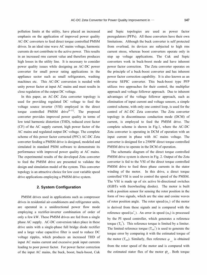
and Sepic topologies are used as power factor preregulators (PFPs). All these converters have their own limitations. Although the buck converter is self protected from overload, its devices are subjected to high rms current stress, whereas boost converters operate only in step up voltage applications. The Cuk and Sepic converters work in buck-boost mode and have inherent power factor correction. The Zeta converter operates on the principle of a buck-boost converter and has inherent power factor correction capability. It is also known as an inverse SEPIC converter. This buck-boost type PFP utilizes two approaches for their control, the multiplier approach and voltage follower approach. Due to inherent advantages of the voltage follower approach, such as elimination of input current and voltage sensors, a simple control scheme, with only one control loop, is used for the control of AC-DC Zeta converter. The Zeta converter topology in discontinuous conduction mode (DCM) of current, is employed to feed the PMSM drive. The complete scheme is shown in Fig.1, where the AC-DC Zeta converter is operating in DCM of operation with an input current in phase with AC mains voltage. The converter is designed for a 2500W direct torque controlled PMSM drive to operate in the DCM of operation.
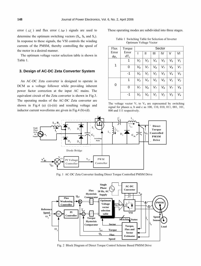
The schematic diagram of the direct torque controlled PMSM drive system is shown in Fig. 2. Output of the Zeta converter is fed to the VSI of the direct torque controlled PMSM drive to feed three phase currents in the stator winding of the motor. In this drive, a direct torque controlled VSI is used to control the speed of the PMSM. The VSI is made up of six active bi-directional switches (IGBTs with freewheeling diodes). The motor is built with a position sensor for sensing the rotor position in the form of two signals, which are the sine and cosine waves of rotor position angle. The rotor speed of the motor
is derived from these signals and is compared with the reference speed . An error in speed (ω
r(ω )
*r(ω ) e) is processed
by the PI speed controller, which generates a reference torque (Tk
*). This reference torque is limited by a limiter. The limited reference torque (Tref
*) is used to generate the torque error by comparing it with the estimated torque of the motor (Test). Similarly, flux reference
srefϕ is obtained
from the rotor speed of the motor and is compared with
the estimated stator flux of the motor sϕ . Both torque
148 Journal of Power Electronics, Vol. 6, No. 2, April 2006 error ( ) and flux error (
eT∆ ϕ∆ ) signals are used to
determine the optimum switching vectors (Sa, Sb and Sc). In response to these signals, the VSI controls the winding currents of the PMSM, thereby controlling the speed of the motor in a desired manner.
Table 1 Switching Table for Selection of Inverter Optimum Voltage Vector
Sector Flux Errordϕs
TorqueError dTe
I II III IV V VI
1 V2 V3 V4 V5 V6 V1
0 V8 V7 V8 V7 V8 V7
1
-1 V6 V1 V2 V3 V4 V5
1 V3 V4 V5 V6 V1 V2
0 V7 V8 V7 V8 V7 V8
0
-1 V5 V6 V1 V2 V3 V4
The voltage vector V1 to V8 are represented by switching signal for phases a, b and c as 100, 110, 010, 011, 001, 101, 000 and 111 respectively.
The optimum voltage vector selection table is shown in Table 1.
3. Design of AC-DC Zeta Converter System
An AC-DC Zeta converter is designed to operate in
DCM as a voltage follower while providing inherent power factor correction at the input AC mains. The equivalent circuit of the Zeta converter is shown in Fig.3. The operating modes of the AC-DC Zeta converter are shown in Fig.4 (a) (i)-(iii) and resulting voltage and inductor current waveforms are given in Fig.4 (b)-(d).
These operating modes are subdivided into three stages.
SwitchingPulse
Ls, Rs
Is
D1Single Phase 50 Hz,
ACSupply
vs
dcV+_
PI VoltageController
PWMController
VdceV dc*
Cdc
+DirectTorque
ControlledPMSMDrive
Vdc
_D4
D3
D2
C1
D5
Diode Bridge
uref
+
Lo
Cf
S1
L1
iL1
iLo
Fig. 1 AC-DC Zeta Converter feeding Direct Torque Controlled PMSM Drive
Torque,Flux and
SectorEstimator
OptimumVoltagevector
selectiontable
Sa,Sb,Sc
Switching Status
VSI
PMSM
ReferenceSpeed
FluxHysterisis
Comparator
TorqueHysterisis
Comparator
SpeedSensor
Sector
Torque
Flux
Speed
FluxWeakeningController
PIController
vdc
ia
ib
ωr*
ωr
AC-DCConverter
SinglePhase
50 Hz, ACSupply
Load
ϕref
Τref
ϕs
Τest
Fig. 2 Block Diagram of Direct Torque Control Scheme Based PMSM Drive

AC-DC Zeta Converter for Power Quality Improvement in … 149
3.1 First Stage of Operation This first stage is defined by the on time ton of switch S1
and is shown in Fig.4 (a)(i). In this stage, the AC mains supply energy to the input inductor (L1). This energy is subsequently transferred to the output inductor Lo through the intermediate capacitor C1. The current in the input inductor (iL1) and output inductor (iLo) increase linearly. The output DC-link capacitor voltage Vdc and the intermediate capacitor voltage vc1 are considered constant in this stage. They are equal to the DC voltage Vdc. In the
first stage of converter operation, the inductor current for 0<t<ton can be defined as:
iL1=i+(v1r/L1)t (1)
iLo=-i+(v1r/Lo) (2)
Where iL1 and iLo represent the current flowing in input inductor L1 and output inductor Lo. Voltage v1r is an absolute value of the sinusoidal input voltage (v1r =|vs|=Vs|sinωt|). While i is the current which exists in both inductors L1 and Lo after diode D5 stops conducting, as shown in Figs. 4(c) and (d).
Cdc
V1r
Vdc
R
-
+
S1
L1
D5
LoC1is
iL1
Cf
iLo
LOAD
EquivalentLoad
Fig. 3 Equivalent circuit of AC-DC Zeta Converter
3.2 Second Stage of Operation In the second stage operation of the Zeta converter,
switch S1 is turned off and diode D5 starts conducting. The stored energy from the input inductance (L1) and output inductance (Lo) are transferred to the intermediate capacitor C1 and the DC link capacitor filter (Cdc), respectively. This stage continues until iL1 becomes equal
(c )
( i) F irs t S ta g e
iL o
v 1 r/ L ov d c / L o
t- i
T s
td o nto n
iL 1
v 1 r/ L 1
v d c / L 1
t
i
v L 1 , v L o
V 1 r
t( i) ( i i) ( i i i)
( i i) S e c o n d S ta g e ( iii) T h ird S ta g e(a )
(b )
(d )
V 1 r
-V d c
L 1
L o
iL o
C d c
R
-
C 1
V 1 r
i L 1
is
+
V d c
L 1
C d c
R
-
C 1
V 1 r
iL 1
+
V d c
S L o
iL o
L 1
C d c
R
-
C 1
V 1 r
iL 1
+
V d c
S L o
iL o
iD 5
Fig. 4 (a) Three Different Operating Stages (i), (ii) and (iii) of Zeta Converter in DCM of Operation and its
(b) Voltage Waveforms (c) and (d) Inductors Current Waveform

150 Journal of Power Electronics, Vol. 6, No. 2, April 2006 to the negative of iLo as shown in Fig.4 (a)(ii). In this stage of Zeta converter operation, switch S1 is off and diode D5 is on for tdon time. The inductor currents iL1 and iLo for the duration, ton<t<tdon are given as:
iL1=i+(v1r/L1)dTs-(Vdc/L1)t (3)
iLo=-i+(v1r/ Lo)dTs-(Vdc/Lo)t (4)
Where ‘d’ is the duty ratio of the switch and is equal to ton/Ts , while Ts is the switching period.
The output diode (D5) duty ratio is related to the duty ratio of the switch as per the following relation:
ddon/d =v1r/Vdc=iLo/ iL1 (5)
The relation of Eq.(5) can be modified as:
tdon=ddonTs=(dTs/Vdc)v1r (6)
Eq.(6) can be further simplified by substituting the value of v1r, hence the on time of diode D5 can be given as:
tdon =(dTs/M) |sinωt| (7)
Where M=Vdc/Vs and Vs is the peak value of the input voltage.
3.3 Third Stage of Operation This freewheeling stage lasts until the start of a new
switching period and is shown in Fig.4 (a)(iii). In this stage of operation neither switch ‘S1’ nor output diode ‘D5’ conducts. The voltage applied across inductances L1 and Lo is zero and their currents are constant until the start of the new switching cycle. The currents iL1 and iLo become equal and opposite at time toff. Therefore, in this stage the output diode current is zero. The switch and output diode OFF time is given as:
toff=Ts-ton-tdon (8)
3.4 Critical inductance for Discontinuous Current Mode Operation of Zeta Converter
The switching period (Ts) average output and input inductance current can be given as:
iL1= 1ron don
1
v d(t +t )+i2L
(9)
iLo= 1ron don
o
v d(t +t )-i2L
(10)
The sum of the input inductor current and the output inductor current can be given as:
iL1+ iLo = 1ron don
eq
v d(t +t )2L
(11)
Where Leq=(L1Lo)/(L1+Lo) (12)
From Eqs.(5) and (9) the input inductor (L1) current iL1 can be given as:
don don1rL1 s
eq
d dvi 1+( )= dT 1+( )dd 2L d
(13)
Eq.(13) can be further simplified as:
21rL1 s
eq
vi = d T2L
(14)
The input inductance current (iL1 ) can be written as:
iL1=(v1rd2Ts)/2Leq=I1|sin(ωt)| (15)
I1=(Vsd2Ts)/2Leq (16)
For successful operation of the Zeta converter in discontinuous current mode the following inequalities must be true:
ton+ tdon <Ts (17)
In the DCM of operation, the value of equivalent inductance Leq obtained from Eq.(12) decides the operation of the Zeta converter. The output inductance (Lo) influences the output voltage ripple. Therefore, this mode of operation mainly depends upon the selection of the input inductance (L1). For maximum loads on the Zeta converter (R=Rmin), the equivalent inductance can be selected by following relation as:
Leq<Rmin(1-d)2(Ts/2) (18)
Where R is equivalent load resistance and is related to output power Pout as: R= V2
dc/Pout.

AC-DC Zeta Converter for Power Quality Improvement in … 151
The output inductor is selected on the basis of
maximum ripple ( ) allowed in the output inductor
current as: Loi∆
1r so
Lo
v dTL =( i )∆
(19)
The input inductance can be found from the Eq.(12) as:
o eq1
o eq
L L L
( L - L ) = (20)
After obtaining the design value of inductances L1 and Lo, the intermediate capacitor C1 is selected by considering the voltage constraints on the capacitor during DCM of operations. Capacitor C1 experiences two conflicting constraints, namely, it have nearly a constant value within the switching period and follows the input voltage profile within a line frequency period. The value of capacitance ‘C1’ shown in Fig.3, is calculated as:
C1=1/ω2ar(L1+Lo) (21)
Where ω< ωar< ωs, and ω is the angular frequency of the AC mains voltage, ωar is the resonant angular frequency of the converter and ωs is the angular switching frequency of the switch (S1).
3.5 Selection of Output DC Capacitive filter The value of the output capacitor is selected on the
basis of the peak-to-peak ripple content allowed in the DC output voltage. The output capacitor is selected from the relation expressed as:
Cdc=1/(2ωrv Rmin) (22)
Where ω is the angular frequency of the AC line voltage, rv is the p.u. ripple content allowed in the DC-link voltage and Rmin is the minimum equivalent load resistance (V2
dc/Pout). These main design equations of the AC-DC Zeta
converter for DCM of operation are given in Table 2. The design values of the converter parameters are computed, and are given in Table 3, while the rating considered for the PMSM drive is given in Table 4.
4. Modeling of the Drive System
The AC-DC Zeta converter feeding the variable speed direct torque controlled-PMSM drive system is modeled and simulated in a standard PSIM package. The complete model of the drive is described in the following sections.
4.1 Modeling of AC-DC Zeta Converter The control scheme of the improved power quality
converter is shown in Fig.1. The converter topology in this case, consists of the following subsystems. 4.1.1 DC-link Voltage Controller
The error between the reference DC link voltage (V*dc)
and the sensed DC link voltage (Vdc) is fed to the PI voltage controller. The output of the controller at the nth sampling instant is given as:
uref(n)=uref(n-1)+KpdcVdce(n)-Vdce(n-1)+KidcVdce(n) (23)
Where, uref(n) is the output of the voltage controller at
Table 2 Design Equations of Zeta Converter
Sr.No
Name of criterion/Component
Design Equation
1 Voltage Ratio M M=Vdc/Vs
2 Duty Ratio of Switch d d=M/(M+1) 3 Ripple Current (A) IRipple IRipple= ri(2Pin/Vs) 4 Inductance Leq Leq =RTs (1-d)2/2 5 Inductance Lo Lo =V1r d Ts/IRipple
6 Inductance L1 L1 =Lo Leq/(Lo- Leq)7 Capacitance C1 C1=1/ω2
ar(Lm+Lo) 8 Capacitance Cdc Cdc=1/(2ωrvR)
Table 3 Design Parameters of Zeta Converter
Sr. No.
Component Design Value
1 Voltage Ratio ‘M’ 0.3692 2 Duty Ratio ‘d’ 0.5128 3 Inductance L1 0.25mH 4 Inductance Lo 0.1mH 5 Capacitance C1 10 µF 6 Filter Capacitance Cf 100nF 7 Ripple Current 2.46A 8 Output Capacitance Cdc 1500 µF 9 PI Voltage Controller Gain
(Kpdc, Kidc) 0.3, 0.029

152 Journal of Power Electronics, Vol. 6, No. 2, April 2006 the nth sampling instant. uref(n-1) is the output of the voltage controller at the (n-1)th sampling instant. V
dce(n) is the error in the DC-link voltage at the nth sampling instant. Kpdc is the proportional gain of the voltage controller and Kidc is the integral gain of the voltage controller. The voltage error in the DC link voltage at the nth instant
is given as:
Vdce(n)=V*dc(n) - Vdc(n) (24) (
The output of the voltage controller (uref), after limiting, is considered a modulating signal for the Pulse Width Modulation (PWM) controller to generate the appropriate duty ratio of switch S1. In the PWM controller, the modulating signal which is output of voltage controller (uref) is compared with the instantaneous value of the triangular carrier wave. If the modulating signal is greater than the triangular carrier wave, then a switching signal is generated for the Metal Oxide Semiconductor Field Effect Transistor (MOSFET) used as switch S1. Otherwise, it is not gated and the freewheeling diode conducts.
4.2 Modeling of Direct Torque Controlled PMSM Drive System
The various components used in the DTC based PMSM drive system are shown in the Fig.2. The modeling equations for the different blocks, which include the PI
speed controller, field weakening controller, flux and torque hysteresis comparators, estimators, Permanent Magnet Synchronous Motor (PMSM) and VSI are given in this section as per the following modeling equations. 4.2.1 PI Speed controller
The PI speed controller input is the speed error between the reference speed and the
sensed motor speed ( . This error is estimated at the
k
ω )e(k)*(ω )r(k)
ω )r(k)th sampling instant as:
*ω ω - ωe(k) r(k) r(k)= (25)
The error is processed in the PI speed controller and the output of the controller is given by the reference torque
at the k*(T )(k)th sampling instant as:
P I(k ) (k-1) (K ) (K -1) (K )* *T T K ω ω K ωe e e= + − + (26)
Where are proportional and integral gains
of the PI controller, respectively. After limiting the output of the PI controller is taken as reference torque .
P Iand K K
*T (k) T(ref)
4.2.2 Field Weakening Control Below the base speed the reference value of the stator
flux linkage is expressed as: Table 4 Specification and Input Data of Zeta Converter
fed PMSM Drive System Sr.No
Parameter Value
1 Input Peak Voltage (Vs) V 325 2 Output Voltage (Vdc) V 340 3 Rated Power of Converter (Pin) W 2500 4 Switching Frequency of PWM Voltage
Controller of Zeta Converter (fs) kHz 50
5 Ripple Current (ri) 10% 6 Rated Output Power of PMSM (Pout) W 2000 7 Stator Resistance (Rs) 0.61Ω 8 Inductance d-axis (Ld) mH 9.1 9 Inductance q-axis (Lq) mH 11.5 10 Back EMF Constant (Eb) V/KRPM 68.80 11 Poles (P) 4 13 Moment of Inertia (J) Kg-m2 0.0015 14 Switching Frequency of PWM Current
Controller of VSI (fc) KHZ 10
15 PI Speed Controller Gains (KP, KI)
1, 0.00125
csrefϕ ϕ= (27)
The reference value of the stator flux linkage is the function of rotor speed for the rotor speed above base speed as:
(ω / ω )csref bϕ ϕ= r (28)
Where cϕ is the rated flux, ωb is base speed and ω
is the rotor speed of the motor.
r
4.2.3 Torque and Flux Hysteresis Comparator
The stator flux linkage and torque are used as feedback in comparisons of their reference values. The torque error

AC-DC Zeta Converter for Power Quality Improvement in … 153 and flux error are fed to the hysteresis band controller which is used for selecting the appropriate voltage vector according to the table of optimum switching (TOS) given in Table 1. The flux error is given as:
ssrefsϕ ϕ∆ = − ϕ and torque error ∆T = T - Te estref are
the output signals of the hysteresis comparator. Where Test is the estimated value of torque. The output of the hysteresis controller can be defined by the following set of equations.
If then d 0ss ssrefϕ ϕ ϕ ϕ− ≤ ∆ = (29)
If then d 1ss ssrefϕ ϕ ϕ ϕ− > ∆ = (30)
If T - T <∆ T then dT =-1eestref e (31)
If T - T =∆ T then dT =0eestref e (32)
If T - T >∆ T then dT =1eestref e (33)
4.2.4 Flux, Torque and Sector Estimator
In this block, the stator fluxes in the stationary reference frame are estimated and from the obtained values of these fluxes and sensed winding currents of the PMSM, the developed electromagnetic torque (Test) is estimated. Finally, the sector in which the flux vector is present is computed from the stator flux. The modeling of the complete estimator block is subdivided into three parts and is given below.
1) Estimation of Stator Flux Linkages: The stator flux linkages, in direct torque controlled
PMSM drives, are needed for three reasons. First, these fluxes are required for the identification of the sector for the optimum voltage vector selection table. Secondly, the estimation of the developed torque of the PMSM drive requires stator flux linkages. And finally, estimation of rotor mechanical speed also needs these fluxes.
The flux linkage in the stationary reference frame can be obtained from the sensed winding currents (ia and ib), and stator voltage (va and vb) which are computed by a
sensed DC link voltage (vdc) and switching functions (Sa, Sb and Sc). These voltages and currents are transformed to a stationary reference frame. The flux estimator provides stator flux linkage in the stationary reference frame ( and )α β coordinates as:
( )v Ri dϕα α α= −∫ t
t⎟⎠
(34)
v Ri dϕβ β β⎛ ⎞⎜⎝
= −∫ (35)
Where v , v , i and iα αβ β can be obtained from the
stationary reference frame transformation as: v = vaα (36a)
2 ) / 3v = (v va bβ + (36b)
i = iaα (37a)
2 ) / 3i = (i ia bβ + (37b)
The estimated stator flux-linkage modulus can be expressed as:
2 2sϕ ϕ ϕα β
⎛⎜⎝ ⎠
= + ⎞⎟ (38)
2) Estimation of Torque: The electromagnetic torque developed by the PMSM
can be obtained from the stator flux linkage and currents in the stationary reference ( and )α β frame as :
3 PT iα αest β β2 2
ϕ ϕ⎛ ⎞⎜ ⎟⎝ ⎠
= −⎛ ⎞⎛ ⎞⎜ ⎟⎜ ⎟⎝ ⎠⎝ ⎠
i (39)
Where, P is the number of poles
3) Estimation of Sector Location of Stator Flux Linkage Vector:
The stationary reference frame ( and )α β stator flux
components are compared to obtain information on which sector the stator flux vector is lies. These sectors are shown in Fig.5. The sectors can be determined on the basis of following mathematical equations as:

154 Journal of Power Electronics, Vol. 6, No. 2, April 2006
If 3 0, then Sector=1andϕ ϕ ϕα β α≥ ≥ (40)
If 3 0, then Sector=2andϕ ϕ ϕα β α< ≥ (41)
If 3 0, then Sector=3andϕ ϕ ϕα β α< < (42)
If 3 0, then Sector=4andϕ ϕ ϕα β α≥ < (43)
If 3 , 0 0, then Sector=5andϕ ϕ ϕ ϕα β α β≤ < < (44)
If 3 , 0 0, then Sector=6andϕ ϕ ϕ ϕα β α β≤ < < (45)
4.2.5 Modeling of PMSM
The stator of the PMSM consists of a balanced three phase winding similar to the conventional synchronous motor. The mathematical model of the PMSM is derived from the synchronous motor under the assumption that the armature EMF is induced by the permanent magnets in place of DC excitation. Assuming that the induced EMF is sinusoidal, and the eddy current and hysteresis losses are negligible, the stator voltage equations in the rotor reference frame are given as[3]:
v =Ri +p +ωq q q r dϕ ϕ (46)
v =Ri +p -ω qrd d dϕ ϕ (47)
Where φq = Lqiq and φd = Ldid +φf, and vq and vd are the d,q axis stator voltages. iq and id are the d,q axis stator currents. Lq and Ld are the d,q axis inductances. φf is the stator flux linkage produced by permanent magnets. R is the stator-winding resistance per phase. ωr is the rotor speed in rad/sec (electrical). The above parameters are given in Table 4.
The developed electromagnetic torque is given as:
3 PT i (L Le q qf d d2 2
ϕ⎛⎜⎝ ⎠
= + −⎛ ⎞⎛ ⎞⎜ ⎟⎜ ⎟⎝ ⎠⎝ ⎠
) i iq⎞⎟
r
(48)
Where, P is the number of poles. The electromagnetic torque is balanced by the load
torque, accelerating torque and damping torque of the system and can be expressed in an electromechanical equation as:
T T B ω Jp ωe L r= + + (49)
Where, TL is the load torque, B is the damping coefficient and J is the moment of inertia.
The model equations can be rearranged in the form of following first order differential equations as:
pi =(v -Ri +ω L i )/Lqr qd d d d
q
(50)
pi =(v -Ri -ω L i ω )/Lq q q r rd d fϕ− (51)
pω =(T -T - Bω )/ Jr e L r (52)
pθ =ωr r (53)
The phase currents are computed using an inverse Park’s transformation as:
i =i Cosθ -i Sinθa r qd r (54)
i =i Cos(θ -2π/3)-i Sin(θ -2π/3)r q rb d (55)
i =i Cos(θ -4π/3)-i Sin(θ -4π/3)c r q rd (56)
Where angle θr is the position of the rotor. 4.2.6 Modeling of VSI
This particular block models the insulated gate bipolar transistor (IGBT) based three-phase voltage source inverter (VSI). The optimum voltage vector is obtained from the output of the hysteresis torque and flux comparators and the sector in which the stator flux vector lies. The inverter voltage can be given by following equations from switching signals Sa, Sb and Sc as:
vdcv = (2S -S -S )a a b3
⎛ ⎞⎜ ⎟⎜ ⎟⎝ ⎠
c (57)
vdcv = (2S -S -S )a cb b3
⎛ ⎞⎜ ⎟⎜ ⎟⎝ ⎠
(58)
vdcv = (2S -S -S )c c a b3
⎛ ⎞⎜ ⎟⎜ ⎟⎝ ⎠
(59)

AC-DC Zeta Converter for Power Quality Improvement in … 155
Where, Sa, Sb and Sc are switching functions (which are
either one or zero). v v va cb, , and v are voltages
of phase winding a, b, c and the DC link, respectively. dc
Quadrature axis
V4(011) Direct axis
V1(100)
V5(001)
V3(010)V2(110)
V6(101)
Sector IV
Sector III
Sector II
Sector I
Sector V
Sector VI
V7(000)V8(111)
Fig. 5 Sectors for Stator Flux Linkage Space Vector
Depending on the output of flux error and torque error the appropriate stator voltage vector is selected according to Table 1. These voltages can be expressed in the rotor reference frame as the forcing functions vd and vq by using the Park’s transformation as:
d a r b r c r2
v = v Cosθ +v Cos(θ -2π/3)+v Cos(θ -4π/3)3
⎛ ⎞⎜ ⎟⎜ ⎟⎝ ⎠
(60)
q a r b r c rv = v Sinθ +v Sin(θ -2π/3)+v Sin(θ -4π/3)⎞
−⎜ ⎟
(61)
s in the m of the PMSM given in equations (50)-(51)
2⎛⎜ ⎟
3⎝ ⎠
These voltages vd and vq are forcing functionodel
Fig. 6 Modeling of AC-DC Zeta Converter in PSIM Software
Fig. 7 Subsystem of Direct Torque Controlled PMSM Drive

156 Journal of Power Electronics, Vol. 6, No. 2, April 2006
ADMC401
AC-DCZeta Converter
SwitchingPulse
S1
L1
Ls, Rs
Is
D1
vs
D4
D3
D2
C1
D5
Diode Bridge
Lo
Cf
Single Phase230V, 50Hz
+_ PIVoltage
Controller
PWMController
VdceUref
Cdc
AC Supply
PermanentMagnet
SynchronousMotor
Load
Gate driverCircuit for IGBT
based VSI Resolver Sin and
Cos SignalsDemodulator Circuit
DSPADMC-401
A
D
C
DACR
S-2
32
PW M PortGate Pulses
2
Vdc
Cosθ
Sin θ
IcIb
DigitalStorage
S1
S6
S5
S4
S3
S2
VSI
Vdc
V*dc
Fig. 8 Experimental Setup of AC-DC Zeta Converter Fed Vector Controlled PMSM Drive
5. Simulation of AC-DC Zeta Converter in PSIM
the % ripple contents of DC link voltage of the
converter.
12-13]
After designing the components of Zeta converter, the
PMSM is modeled in the direct torque control mode. The standard PSIM software is used to model the AC-DC Zeta converter. The PI voltage controller block, optimum voltage vector selection table and circuit components are shown in Fig.6. The direct torque controlled PMSM drive is connected through a switch so that after stabilization of the DC link voltage, the PMSM drive can be energized. The subsystem model of the direct torque controlled PMSM drive model is given separately in Fig.7, where generation of the reference torque, speed feedback block, torque and flux estimation block, VSI block and PI speed controller block are shown separately. The optimum switching pulses are selected from the voltage vector selection table to generate switching pulses for the VSI of the direct torque controlled PMSM drive. The load torque is represented as an equivalent current source connected to the mechanical-electrical block of the PSIM library. The power quality is analyzed through FFT of the input mains current and
6. DSP Based Hardware Implementation of
AC-DC Zeta Converter
The proposed AC-DC Zeta converter for feeding the VSI of direct torque controlled PMSM drive is implemented using the digital signal processor (DSP) ADMC401 of Analog Devices (AD). The test setup used for the experimental verification of the design and simulation model of the AC-DC Zeta converter is shown in Fig. 8. The control algorithm for the DCM of current operation of the Zeta converter and the direct torque controlled PMSM drive system are implemented in the DSP[ . In this experimental work, the Insulated Gate Bipolar Transistor (IGBT) is used as a switching device for realizing the converter. A 20kHz switching frequency is used for the IGBT switch. The Toshiba made TLP250 IC is used for the driver circuit of the IGBT. The software used for implementation of the AC-DC Zeta converter and direct torque controlled PMSM drive is written in assembly language for the Analog Devices digital signal processor ADMC401.

AC-DC Zeta Converter for Power Quality Improvement in … 157
Fig. 9 Dynamic and Load Perturbation Response of the Direct Torque Controlled PMSM Drive Fed by AC-DC Zeta Converter
7. Results and Discussion
The main design equations of the converter system are shown in Table 2, and obtained parameters of converter are given in Table 3. The input parameter of the converter and specification of the PMSM drive is listed in Table 4. The parameters of the Zeta converter obtained from design equations are used to model the AC-DC Zeta converter in DCM of current operation while feeding the direct torque
controlled PMSM drive. The complete modeling is performed in standard PSIM software. The power quality performance indices for the AC-DC Zeta converter feeding the direct torque controlled PMSM drive are obtained and are given in Table 5. Whereas, the stress on diode and switch as a normalized function of input peak current (15A) and input peak voltage (325V) are given in Table 6. The dynamic performance of the PMSM drive
0.88 0.885 0.89 0.895 0.9 0.905 0.91 0.915 0.92-20
-10
0
10
20
AC
Mai
ns C
urre
nt(A
)
time (s)
0 200 400 600 800 1000 1200 1400 1600 1800 20000
20
40
60
80
100 Fundamental (50 Hz)= 13.1787
Mag
(% o
f 50
Hz
com
pone
nt)
Frequency (Hz)
THD=3.85%
Fig.11 (a) AC Mains Current waveform at 100%Load (2000W) on AC-DC Zeta Converter fed Direct Torque Controlled PMSM drive (b) Harmonic Spectrum of AC Mains Current
0.96 0.965 0.97 0.975 0.98 0.985 0.99 0.995 1-4
-2
0
2
4
AC
Mai
ns C
urre
nt(A
)
time (s)
0 200 400 600 800 1000 1200 1400 1600 1800 20000
20
40
60
80
100 Fundamental (50 Hz)= 2.76633
Mag
(% o
f 50
Hz
com
pone
nt)
Frequency (Hz)
THD=6.13%
Fig. 10 (a) AC Mains Current waveform at 20%Load (400W) on AC-DC Zeta Converter fed Direct Torque Controlled PMSM drive (b) Harmonic Spectrum of AC Mains Current

158 Journal of Power Electronics, Vol. 6, No. 2, April 2006 and its load perturbation response is given in Fig.9. The harmonic spectrum of the AC mains current at partial load (400W) is given in Fig.10, whereas the rated load (2000W) is given in Fig.11. The switching stress on the diode and switch of the Zeta converter are given in Fig.12. The test results on the AC-DC Zeta converter feeding the direct torque controlled PMSM drive for starting and steady state operation are shown in Figs.13-14. The harmonic spectrum of the AC mains current at different loads on the AC-DC Zeta converter feeding direct torque controlled PMSM drive are shown in Figs. 15(a)-(b). From these results, the following observations are made:
7.1 Dynamic Performance of PMSM Drive The dynamic response of the direct torque controlled
PMSM at load (2000W) is shown in Fig.9. The input AC mains current remains sinusoidal and in phase with the AC mains voltage during the starting of the drive. The DC link voltage recovers back to the reference value within a few cycles due to the action of PI voltage controller.
7.2 Load Perturbation Performance of PMSM Drive
The load perturbation response of the direct torque controlled PMSM drive fed from the AC-DC Zeta converter is shown in Fig.9 in terms of the AC mains current, AC mains voltage, DC link voltage, PMSM winding currents, speed torque and flux waveforms. It is evident from the load perturbation response that when the load on the motor is changed a dip and a rise are observed in the DC link voltage. As the load on the motor is increased from 1000W to 2000W a voltage dip of 25V takes place and subsequently the steady value of DC link voltage is restored within 120msec due to the restoring action of PI voltage controller.
7.3 Power Quality at AC Mains Improvements in the power quality of the AC mains
feeding the direct torque controlled PMSM drive is analysed for the proposed topology of the Zeta converter in DCM of current operation. Power quality is examined by observing the Total Harmonic Distortion (THD), Crest
Table 5 Power Quality Performance Indices of Zeta Converter Feeding PMSM Drive
Sr. No
%Load %THDof Is
DF DPF PF CF of Is
Isrms PinWatts
RF %
%p-p Ripple
Vdc Volts
1 20% 6.13 .998 .999 .997 1.82 1.98 454.03 .242 .588 340 2 40% 5.55 .998 .999 .997 1.65 3.88 889.72 .403 1.029 340 3 60% 5.21 .998 .999 .997 1.55 5.73 1313.9 .616 1.441 340 4 80% 4.62 .998 .999 .997 1.46 7.51 1722.1 .792 2.051 340
5 100% 3.85 .999 .999 .998 1.42 9.33 2143.3 .907 2.353 340
Table 6 Normalized Current and Voltage of Zeta Converter Feeding PMSM Drive
Sr. No
Normalized Quantity
Average Value
RMS Value
Peak Value
1 Normalized Diode Current
0.759 1.461 4.141
2 Normalized Diode Voltage
1.049 1.473 3.162
3 Normalized Switch Current
1.442 2.342 4.272
4 Normalized Switch Voltage
0.945 1.287 2.341
Fig. 12 Diode and Switch Stress of the Zeta Converter Feeding Direct Torque Controlled PMSM Drive

AC-DC Zeta Converter for Power Quality Improvement in … 159 Factor (CF), Power Factor (PF), Distortion Factor (DF), Displacement Power Factor (DPF) and RMS value of the AC mains current. The %THD of AC mains current is found to be 6.13% at 20% of rated load (400W) on the motor. This improved to 3.85% when the load on the motor was increased to 100% of the rated value (2000W). The power quality of the DC-bus voltage of the Zeta converter, which is feeding the VSI of the direct torque controlled PMSM drive, is also computed for available DC-link voltage, Ripple Factor (RF) and percentage peak-
peak ripple of output DC voltage. The RF of the DC bus voltage of the Zeta converter is found to be 0.242% at 20% of the rated load (400W) and its value is observed to be 0.907% with the increased load of 100% of the rated load (2000W) on the motor.
7.4 Stresses on the Diode and Switch of Zeta Converter
Due to the DCM of current operation both the diode and MOSFET switch (S1) of the converter have experienced
Vs (
V) , i
s(A)
ωr (
Rad
/s)
i a (A
)
Fig. 13 AC Mains Voltage, AC Mains Current, rotor speed and PMSM winding Current waveform of AC-DC Zeta Converter feeding direct torque controlled PMSM drive during starting with reference speed of 225Rad/s. (Scale on X-axis 1div=20ms, Y-axis channel-1 1div =200V, channel-2 1div =2.5A, channel-3 1div= 225Rad/sec, channel-4 1div= 5A)
Vs (
V) , i
s(A)
Fig. 14 AC Mains Voltage, AC Mains Current, rotor speed and PMSM winding Current waveform of AC-DC Zeta Converter feeding direct torque controlled PMSM drive running at 225 Rad/s speed with 200W on motor. (Scale on X-axis 1div=20ms, Y-axis channel-1 1div =125V, channel-2 1div =5A, channel-3 1div= 225Rad/s, channel-4 1div= 5A)
ωr (
Rad
/s)
i a(A
)

160 Journal of Power Electronics, Vol. 6, No. 2, April 2006
Fig. 15(a) Harmonic Spectrum of AC Mains Current at 60W Load on AC-DC Zeta Converter fed DTC PMSM Drive
Fig. 15(b) Harmonic Spectrum of AC Mains Current at 200W of Load on AC-DC Zeta Converter fed DTC PMSM Drive
higher current and voltage stresses. However due to application of converter for small rating (2 kW) loads the maximum current and voltage stress experienced by the diode and switch are within the operating limits of commercially available diodes and MOSFETs. The stress on the switch and diode is tabulated in Table 6 and is shown in Fig.12. It is found that at 100% rated load (2000W) the diode rms current stress is 1.461p.u. and peak current stress is 4.141 p.u., respectively. The same current stresses on the switch are observed as 2.342 p.u. and 4.272 p.u. respectively. The rms voltage stress on the diode is 1.473 p.u. and the peak voltage stress is 3.162 p.u. respectively. Whereas, the rms voltage and peak voltage stresses for the switch are found to be 1.287 p.u. and 2.341 p.u., respectively.
7.5 Experimental Validation Test results are obtained from the developed AC-DC
Zeta converter used for feeding the VSI of the direct torque controlled PMSM drive. The prototype Zeta
converter was developed in the laboratory environment for a 200W rating to validate the simulation model of the Zeta converter and PMSM drive system. The test results are shown in Figs.13-15. The performance of the Zeta converter is observed for starting of direct torque controlled PMSM drive and is given in Fig.13. The performance of the Zeta converter is observed for steady state operating condition of the direct torque controlled PMSM drive and is shown in Fig.14. The harmonic spectrum of the AC mains current at 60W load and 200W load on the Zeta converter feeding the direct torque controlled PMSM drive are shown in Fig. 15(a) and Fig. 15(b), respectively. The experimental results verify the developed design and confirm the effectiveness of AC-DC isolated Zeta converter.
8. Conclusions
Design modeling and development of an AC-DC Zeta
converter was carried out in DCM of current operation to

AC-DC Zeta Converter for Power Quality Improvement in … 161 feed a direct torque controlled PMSM drive. With designed parameters for the Zeta converter, simulation was carried out in standard PSIM software. The simulated and experimental results show improved performance of the proposed AC-DC Zeta converter fed direct torque controlled PMSM drive in terms of low THD of supply current and improved power factor at the AC mains. The smooth starting of the PMSM drive was demonstrated by the drive system, without affecting the quality of the AC mains. It was observed that the Zeta converter in discontinuous conduction mode of current provides improved power quality and acts as a PFP with reduced sensors and a high reliability converter configuration. The direct torque controlled PMSM drive provides acceptable power quality and high efficiency and thus may be suitable for adjustable speed drive applications in residential appliances, such as refrigeration and air conditioning.
References [1] T. J. E. Miller, Brushless Permanent Magnet and
Reluctance Motor Drives, Clarendon Press, Oxford, 1989. [2] Y. Dote and S. Kinoshita, Brushless Servomotors
Fundamentals and Applications, Clarendon Press, Oxford, 1990.
[3] P. Vas, Sensorless Vector and Direct Torque Control, Oxford University Press, 1998.
[4] Electromagnetic compatibility (EMC)-Part-3: Limits- Section 2: Limits for Harmonic Current Emissions (equipment input current<16A per phase), IEC 61000-3-2 Document, Second Edition, 2000.
[5] IEEE Recommended Practices and Requirements for Harmonics Control in Electric Power System, IEEE Standard 519, 1992.
[6] A. Peres, D. C. Martins and I. Barobo, “Zeta Converter Applied in Power Factor Correction”, in Proc. IEEE PESC’94, 1994, pp.1152-1157.
[7] J. Uceeda, J. Sebastian and F.S. Dos Reis, “Power Factor Preregulators Employing the Flyback and Zeta Converters in FM Mode”, in Proc. IEEE CIEP’96, 1996, pp.132-137.
[8] D.C. Martins, “Zeta Converter Operating in Continuous Conduction Mode Using the Unity Power Factor Technique”, in Proc. IEE PEVSD’96, 1996, pp.7-11.
[9] F. T. Wakabayashi, M. J. Bonato, and C. A. Canesin, “The Novel High-Power-Factor ZCS-PWM Preregulators”, IEEE Trans. on Indus. Electron, vol.48, no.2, pp.322-333, April 2001.
[10] T. F. Wu, S. A. Ljang and Y. M. Chen, “Design Optimization for Asymmetrical ZVS-PWM Zeta Converter”, IEEE Trans. on Aerospace and Electronic Systems vol. 39, no.2, pp. 521-532, April 2003.
[11] J. L.Lin, S.P. Yang and P.W. Lin , “Small Signal Analysis and Controller Design for an Isolated Zeta Converter with High Power Factor Correction”, Electric Power System Research, vol. 76, pp. 67-76, July 2005.
[12] Yasuhiko Dote, “Servo motor and motion control using Digital Signal Processors”, Prentice Hall, Eagle Wood, Cliffs, New Jersey, 1990.
[13] User’s Guide of Motion Control DSP ADMC401 of Analog Devices, 1999.
Bhim Singh was born in Rahamapur (U.P.), India, in 1956. He received B.E.(Electrical) degree from the University of Roorkee, Roorkee, India, in 1977 and M.Tech. and Ph.D. degrees from Indian Institute of Technology(IIT), New Delhi, India, in 1979
and 1983, respectively. In 1983, he joined Department of Electrical Engineering, University of Roorkee, as a lecturer. In 1988, he became a reader. In December 1990, he joined Department of Electrical Engineering, IIT, New Delhi, India, as an Assistant Professor. He became an Associate Professor in 1994 and a Professor in 1997. His fields of interest include power electronics, electrical machines and drives, active filters, static compensators, and analysis and digital control of electrical machines. Prof. Singh is a Fellow of the Indian National Academy of Engineering, Institution of Engineers (India), and Institution of Electronics and Telecommunication Engineers and a Life Member of the Indian Society for Technical Education, System Society of India, and National Institution of Quality and Reliability.
B. P. Singh was born in Singhia, Bihar, India, in 1940. He received B.Sc.(Engg.) degree from the Bihar Institute of Technology Sindri(Bihar), India, in 1963, M.E. from Bengal Engineering College Howrah(W.B.)and Ph.D. degrees from
Indian Institute of Technology(IIT), New Delhi, India, in 1966 and 1974, respectively. In 1966, he joined the Department of Electrical Engineering, M.I.T. Muzaffarpur, as an Assistant Professor. In 1978, he joined Department of Electrical Engineering, IIT, Delhi, India, as an Assistant Professor. He became full Professor in 1985. He was visiting professor at California State University Long Beach USA from 1988 to 1990. Presently he is an Emeritus Fellow in the Department of

162 Journal of Power Electronics, Vol. 6, No. 2, April 2006
Electrical Engineering at IIT New Delhi. His fields of interest include Energy conservation in electrical machines and drives, and analysis and control of electrical machines. Prof. Singh is a Fellow of the Institution of Engineers(India), and a Life Member of the Indian Society for Technical Education.
Sanjeet Dwivedi was born in Chhatarpur (M.P.) India, in 1968. He received B.E. (Electrical) degree from the Government Engineering College Jabalpur, India, in 1991 and the M.E. degree (with Gold Medal) from the University of Roorkee, Roorkee, India,
in 1999. In 1991, he joined Larson and Toubro Ltd as Graduate Engineer Trainee. In November 1993 he joined as Lecturer at Department of Electrical Engineering, Indira Gandhi Engineering College Sagar(M.P.), whrere he became Senior Lecturer in 1999 and Reader in 2004. He is currently perusing his Ph.D. degrees in Department of Electrical Engineering, I.I.T., New Delhi, India. His research interests are in area of, digital control of Permanent Magnet Brushless Motors, sensor reduction techniques in ac drives and power quality improvement aspects of ac drives.