abstract test suite for mpls oam - broadband forum · ... lsp traceroute for ldp lsp using reply...
TRANSCRIPT

TECHNICAL REPORT
© The Broadband Forum. All rights reserved.
TR-292
Abstract Test Suite For MPLS OAM
Issue: 1
Issue Date: June 2015

Abstract Test Suite For MPLS OAM TR-292 Issue 1
June 2015 © The Broadband Forum. All rights reserved 2 of 41
Notice
The Broadband Forum is a non-profit corporation organized to create guidelines for broadband
network system development and deployment. This Broadband Forum Technical Report has been
approved by members of the Forum. This Broadband Forum Technical Report is not binding on
the Broadband Forum, any of its members, or any developer or service provider. This Broadband
Forum Technical Report is subject to change, but only with approval of members of the Forum.
This Technical Report is copyrighted by the Broadband Forum, and all rights are reserved.
Portions of this Technical Report may be copyrighted by Broadband Forum members.
THIS SPECIFICATION IS BEING OFFERED WITHOUT ANY WARRANTY
WHATSOEVER, AND IN PARTICULAR, ANY WARRANTY OF NONINFRINGEMENT IS
EXPRESSLY DISCLAIMED. ANY USE OF THIS SPECIFICATION SHALL BE MADE
ENTIRELY AT THE IMPLEMENTER'S OWN RISK, AND NEITHER the Forum, NOR ANY
OF ITS MEMBERS OR SUBMITTERS, SHALL HAVE ANY LIABILITY WHATSOEVER
TO ANY IMPLEMENTER OR THIRD PARTY FOR ANY DAMAGES OF ANY NATURE
WHATSOEVER, DIRECTLY OR INDIRECTLY, ARISING FROM THE USE OF THIS
SPECIFICATION.
Broadband Forum Technical Reports may be copied, downloaded, stored on a server or otherwise
re-distributed in their entirety only, and may not be modified without the advance written
permission of the Broadband Forum.
The text of this notice must be included in all copies of this Broadband Forum Technical Report.

Abstract Test Suite For MPLS OAM TR-292 Issue 1
June 2015 © The Broadband Forum. All rights reserved 3 of 41
Issue History
Issue Number Approval Date Publication
Date
Issue
Editor
Changes
1 1 June 2015 10 June 2015 Yuanlong Jiang,
Huawei
Original
Comments or questions about this Broadband Forum Technical Report should be directed to
Editor Yuanlong Jiang Huawei Technologies Co., Ltd.
IP/MPLS & Core
WG Chairs
David Sinicrope
Drew Rexrode
Ericsson
Verizon

Abstract Test Suite For MPLS OAM TR-292 Issue 1
June 2015 © The Broadband Forum. All rights reserved 4 of 41
Table of Contents
EXECUTIVE SUMMARY ............................................................................................................ 6
1 PURPOSE AND SCOPE ....................................................................................................... 7
1.1 PURPOSE............................................................................................................................ 7 1.2 SCOPE ................................................................................................................................ 7
2 REFERENCES AND TERMINOLOGY ............................................................................. 8
2.1 CONVENTIONS ................................................................................................................... 8 2.2 REFERENCES ..................................................................................................................... 8
2.3 DEFINITIONS ...................................................................................................................... 9 2.4 ABBREVIATIONS .............................................................................................................. 10
3 TECHNICAL REPORT IMPACT ..................................................................................... 11
3.1 ENERGY EFFICIENCY ....................................................................................................... 11 3.2 IPV6 ................................................................................................................................ 11 3.3 SECURITY ........................................................................................................................ 11 3.4 PRIVACY.......................................................................................................................... 11
4 INTRODUCTION ................................................................................................................ 12
5 TEST CONFIGURATION .................................................................................................. 13
6 TEST CASES SUMMARY ................................................................................................. 14
6.1 OAM FOR MPLS LSP ..................................................................................................... 14
6.2 OAM FOR PW ................................................................................................................. 14
6.2.1 OAM for SS-PW ......................................................................................................... 14
6.2.2 OAM for MS-PW ........................................................................................................ 14 6.3 PACKET LOSS & DELAY MEASUREMENT FOR LSP/PW ................................................... 15
7 TEST PROCEDURES ......................................................................................................... 16
7.1 TEST PROCEDURE 1 FOR LSP PING .................................................................................. 16 7.2 TEST PROCEDURE 2 FOR LSP TRACEROUTE..................................................................... 16
8 TEST CASE TEMPLATE ................................................................................................... 17
9 ABSTRACT TEST CASES FOR MPLS OAM ................................................................. 18
9.1 OAM FOR MPLS LSP ..................................................................................................... 18 Test Case 1: LSP Ping for LDP LSP with reply mode 2 (Reply via an IPv4 UDP packet) ... 18
Test Case 2: LSP Ping for RSVP-TE LSP using reply mode 2 (Reply via an IPv4 UDP
packet) .................................................................................................................................... 20 Test Case 3: LSP Traceroute for LDP LSP using reply mode 2 (Reply via an IPv4 UDP
packet) .................................................................................................................................... 21 Test Case 4: LSP Traceroute for RSVP-TE LSP using reply mode 2 (Reply via an IPv4 UDP
packet) .................................................................................................................................... 23 Test Case 5: BFD Session Initialization using LSP Ping ....................................................... 24 Test Case 6: BFD Fault Detection ......................................................................................... 25

Abstract Test Suite For MPLS OAM TR-292 Issue 1
June 2015 © The Broadband Forum. All rights reserved 5 of 41
9.2 OAM FOR PW ................................................................................................................. 26
9.2.1 OAM for SS-PW ......................................................................................................... 26
Test Case 7: BFD with VCCV using PW-ACH ...................................................................... 26 Test Case 8: BFD with VCCV for static PW (with IPv4 UDP headers) ................................ 27 Test Case 9: BFD with VCCV using PW-ACH for LDP signaled PW (without IP/UDP
headers) .................................................................................................................................. 29 Test Case 10: BFD with VCCV for LDP signaled PW (with IPv4/UDP headers) ................ 30 Test Case 11: VCCV LSP Ping using PW-ACH ..................................................................... 31
9.2.2 OAM for MS-PW ........................................................................................................ 33 Test Case 12: MS-PW E2E Connectivity Verification using VCCV Ping (In-Band VCCV) .. 33 Test Case 13: MS-PW partial Connectivity Verification using VCCV Ping (TTL Expiry
VCCV) .................................................................................................................................... 35 Test Case 14: Including FEC 129 Sub-TLV in SP-PE TLV by an S-PE ................................ 37
9.3 PACKET LOSS & DELAY MEASUREMENT FOR LSP/PW ................................................... 39 Test Case 15: Packet loss measurement for LSP/PW ............................................................ 39
Test Case 16: Delay measurement for LSP/PW ..................................................................... 40
Abstract Test Suite For MPLS OAM TR-292 Issue 1
June 2015 © The Broadband Forum. All rights reserved 6 of 41
Executive Summary
TR-292 defines testing and validation procedures based on requirements for MPLS OAM in
MPLS Mobile Backhaul Networks as specified in TR-221.
The test procedures are based on requirements as described in the following documents:
Broadband Forum TR-221 “Technical Specifications for MPLS in Mobile Backhaul
Networks”,
Broadband Forum TR-221C1 “Technical Specifications for MPLS in Mobile Backhaul
Networks - Corrigendum 1”,
RFC 4379 “Detecting Multi-Protocol Label Switched (MPLS) Data Plane Failures”,
RFC 5085 “Pseudowire Virtual Circuit Connectivity Verification (VCCV): A Control
Channel for Pseudowires”,
RFC 5880 “Bidirectional Forwarding Detection (BFD)”,
RFC 5884 “Bidirectional Forwarding Detection (BFD) for MPLS Label Switched Paths
(LSPs)”,
RFC 5885 “Bidirectional Forwarding Detection (BFD) for the Pseudowire Virtual Circuit
Connectivity Verification (VCCV)”,
RFC 6310 “Pseudowire (PW) Operations, Administration, and Maintenance (OAM)
Message Mapping” and
RFC 6474 “Packet Loss and Delay Measurement for MPLS Networks”.

Abstract Test Suite For MPLS OAM TR-292 Issue 1
June 2015 © The Broadband Forum. All rights reserved 7 of 41
1 Purpose and Scope
1.1 Purpose
TR-292 describes the requirements and corresponding test procedures to be used when testing
MPLS OAM for use in MPLS Mobile Backhaul Networks.
Vendors can refer to the requirements and test procedures defined in this specification in the
development and commercial cycles of their products and carriers can use them to ensure that the
network elements they deploy or add to their existing network will have the ability to deliver
MPLS OAM based on TR-221.
1.2 Scope
An overview of the testing requirements that would comprise this Abstract Test Suite for MPLS
OAM is provided as follows:
OAM test for MPLS LSP, including LSP Ping and BFD profiles for LSP as listed in TR-221;
OAM test for Pseudowire, including BFD with VCCV and LSP Ping with VCCV profiles as
listed in TR-221; and
Packet loss & delay measurement for LSP/PW.
Abstract Test Suite For MPLS OAM TR-292 Issue 1
June 2015 © The Broadband Forum. All rights reserved 8 of 41
2 References and Terminology
2.1 Conventions
In this Technical Report, several words are used to signify the requirements of the specification.
These words are always capitalized. More information can be found be in RFC 2119 [1].
MUST,
SHALL
This word, or the term “REQUIRED”, means that the definition is an
absolute requirement of the specification.
MUST NOT This phrase means that the definition is an absolute prohibition of the
specification.
SHOULD This word, or the adjective “RECOMMENDED”, means that there
could exist valid reasons in particular circumstances to ignore this
item, but the full implications need to be understood and carefully
weighed before choosing a different course.
SHOULD NOT This phrase, or the phrase "NOT RECOMMENDED" means that there
could exist valid reasons in particular circumstances when the
particular behavior is acceptable or even useful, but the full
implications need to be understood and the case carefully weighed
before implementing any behavior described with this label.
MAY This word, or the adjective “OPTIONAL”, means that this item is one
of an allowed set of alternatives. An implementation that does not
include this option MUST be prepared to inter-operate with another
implementation that does include the option.
2.2 References
The following references are of relevance to this Technical Report. At the time of publication, the
editions indicated were valid. All references are subject to revision; users of this Technical
Report are therefore encouraged to investigate the possibility of applying the most recent edition
of the references listed below.
A list of currently valid Broadband Forum Technical Reports is published at
www.broadband-forum.org.
Document Title Source Year
[1] RFC 2119 Key words for use in RFCs to Indicate
Requirement Levels
IETF 1997
[2] TR-221 Technical Specifications for MPLS in
Mobile Backhaul Networks
Broadband Forum 2011
[3] TR-221C1 Technical Specifications for MPLS in Broadband Forum 2014
Abstract Test Suite For MPLS OAM TR-292 Issue 1
June 2015 © The Broadband Forum. All rights reserved 9 of 41
Mobile Backhaul Networks -
Corrigendum 1
[4] RFC 4378 A Framework for Multi-Protocol
Label Switching (MPLS) Operations
and Management (OAM)
IETF 2006
[5] RFC 4379 Detecting Multi-Protocol Label
Switched (MPLS) Data Plane Failures
IETF 2006
[6] RFC 5085 Pseudowire Virtual Circuit
Connectivity Verification and
Framework
IETF 2007
[7] RFC 5880 Bidirectional Forwarding Detection
(BFD)
IETF 2010
[8] RFC 5884 Bidirectional Forwarding Detection
(BFD) for MPLS Label Switched
Paths (LSPs)
IETF 2010
[9] RFC 5885 Bidirectional Forwarding Detection
(BFD) for the Pseudowire Virtual
Circuit Connectivity Verification
(VCCV)
IETF 2010
[10] RFC 5994 Application of Ethernet Pseudowires
to MPLS Transport Networks
IETF 2010
[11] RFC 6310 Pseudowire (PW) Operations,
Administration, and Maintenance
(OAM) Message Mapping
IETF 2011
[12] RFC 6374 Packet Loss and Delay Measurement
for MPLS Networks IETF 2011
2.3 Definitions
The following terminology is used throughout this Technical Report.
Customer Edge A device where one end of a service originates and/or terminates. The CE is
not aware that it is using an emulated service rather than a native service
Provider Edge A device that provides pseudowire emulation of a native service to a CE
Pseudowire A connection between two PEs carried over a PSN. The PE provides the
adaptation between the CE and the PW
Ingress The point where the native service such as Ethernet is encapsulated into a
pseudowire PDU (ETH to PSN direction)
Egress The point where the native service such as Ethernet is decapsulated from a
pseudowire PDU (PSN to ETH direction)
DUT Device Under Testing

Abstract Test Suite For MPLS OAM TR-292 Issue 1
June 2015 © The Broadband Forum. All rights reserved 10 of 41
Protocol
Analyzer
A device which can emulate and analyze the specific network protocol
2.4 Abbreviations
This Technical Report uses the following abbreviations:
AC Attachment Circuit
BFD Bidirectional Forwarding Detection
CE Customer Edge
DM Delay Measurement
LM Loss Measurement
LSP Label Switched Path
OAM Operations, Administration and Maintenance
PE Provider Edge
PW Pseudowire
WG Working Group
TR Technical Report

Abstract Test Suite For MPLS OAM TR-292 Issue 1
June 2015 © The Broadband Forum. All rights reserved 11 of 41
3 Technical Report Impact
3.1 Energy Efficiency
TR-292 has no impact on energy efficiency.
3.2 IPv6
TR-292 has no impact on IPv6.
3.3 Security
TR-292 has no impact on security.
3.4 Privacy
TR-292 has no impact on privacy.

Abstract Test Suite For MPLS OAM TR-292 Issue 1
June 2015 © The Broadband Forum. All rights reserved 12 of 41
4 Introduction
TR-292 describes the requirements and corresponding test procedures to be used when testing
MPLS OAM in MPLS Mobile Backhaul Networks.
Vendors can refer to the requirements and test procedures defined in this specification in the
development and commercial cycles of their products and carriers can use them to ensure that the
network elements they deploy or add to their existing network will have the ability to deliver
MPLS OAM based on TR-221 [2].
Note: The purpose of this TR is to validate the protocols and procedures of the referenced RFCs
and standards. Where there is discrepancy between this document and the referenced RFCs and
standards, the RFCs and standards take precedence.
Abstract Test Suite For MPLS OAM TR-292 Issue 1
June 2015 © The Broadband Forum. All rights reserved 13 of 41
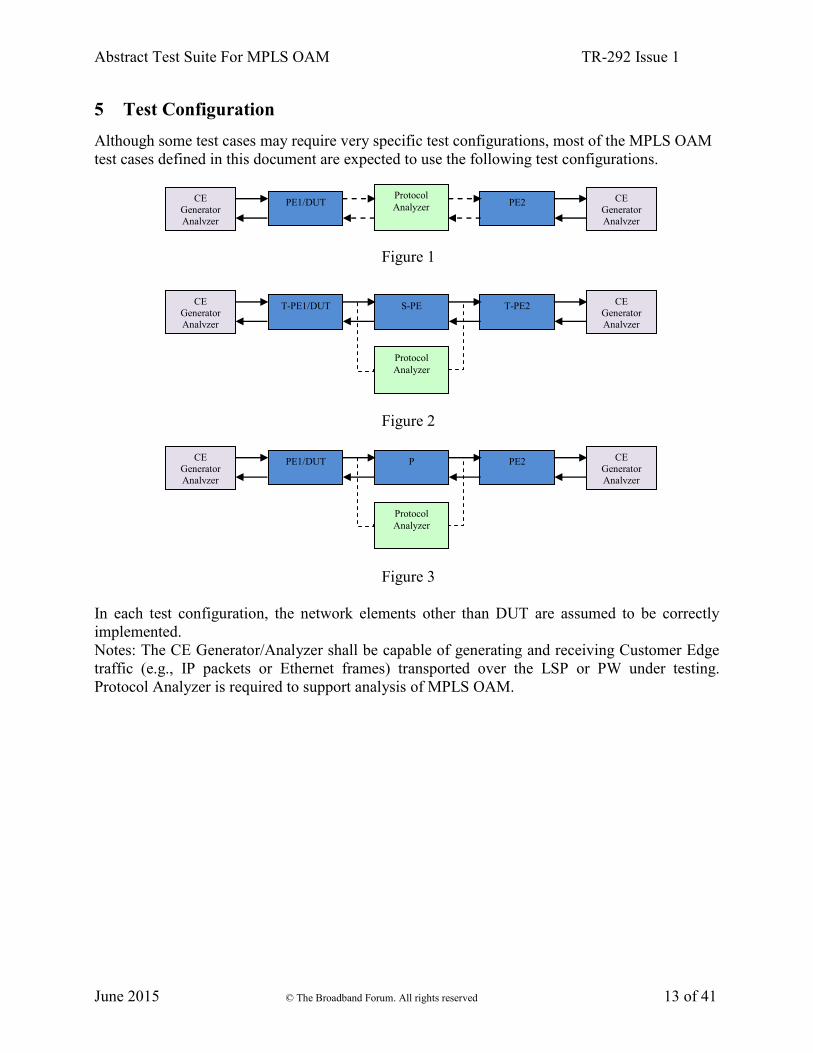
5 Test Configuration
Although some test cases may require very specific test configurations, most of the MPLS OAM
test cases defined in this document are expected to use the following test configurations.
Figure 1
Figure 2
Figure 3
In each test configuration, the network elements other than DUT are assumed to be correctly
implemented.
Notes: The CE Generator/Analyzer shall be capable of generating and receiving Customer Edge
traffic (e.g., IP packets or Ethernet frames) transported over the LSP or PW under testing.
Protocol Analyzer is required to support analysis of MPLS OAM.
CE
Generator
Analyzer
T-PE1/DUT
Protocol
Analyzer
T-PE2 CE
Generator
Analyzer
S-PE
CE
Generator
Analyzer
PE1/DUT
Protocol
Analyzer
PE2 CE
Generator
Analyzer
P
CE
Generator
Analyzer
PE1/DUT Protocol
Analyzer PE2
CE
Generator
Analyzer

Abstract Test Suite For MPLS OAM TR-292 Issue 1
June 2015 © The Broadband Forum. All rights reserved 14 of 41
6 Test Cases Summary
6.1 OAM for MPLS LSP
Number Test Case Name Test Status
1 (TR221-
5.2.1-1)
LSP Ping for LDP LSP with reply mode 2 (Reply via an IPv4 UDP
packet) Mandatory if LDP is supported
2 (TR221-
5.2.1-2)
LSP Ping for RSVP-TE LSP with reply mode 2 (Reply via an IPv4
UDP packet) Mandatory if RSVP-TE is supported
3 (TR221-
5.2.1-3)
LSP Traceroute for LDP LSP with reply mode 2 (Reply via an IPv4
UDP packet) Mandatory if LDP is supported
4 (TR221-
5.2.1-4)
LSP Traceroute for RSVP-TE LSP with reply mode 2 (Reply via an
IPv4 UDP packet) Mandatory if RSVP-TE is supported
5 (TR221-
5.2.1-5) BFD Session Initialization using LSP Ping Mandatory
6 (TR221-
5.2.1-6) BFD Fault Detection Mandatory
6.2 OAM for PW
6.2.1 OAM for SS-PW
Number Test Case Name Test Status
7 (TR221-
5.2.3.1-1) BFD with VCCV using PW-ACH Mandatory
8 (TR221-
5.2.3.1-2) BFD with VCCV for Static PW (with IPv4 UDP headers) Optional
9 (TR221-
5.2.3.1-3)
BFD with VCCV using PW-ACH for LDP signaled PW (without
IP/UDP headers) Mandatory if LDP is supported
10 (TR221-
5.2.3.1-4)
BFD with VCCV using PW-ACH for LDP signaled PW (with
IPv4/UDP headers) Optional
11 (TR221-
5.2.3.1-5) VCCV LSP Ping using PW-ACH Mandatory
6.2.2 OAM for MS-PW
Number Test Case Name Test Status
12 (TR221-
5.2.3.2-1)
MS-PW end to end Connectivity Verification using VCCV Ping (In-
Band VCCV) Optional
13 (TR221-
5.2.3.2-2)
MS-PW partial Connectivity Verification using VCCV Ping (TTL
Expiry VCCV) Optional
14 (TR-221-
5.2.3.2-3) Including FEC 129 Sub-TLV in SP-PE TLV by an S-PE
Optional, applicable if FEC 129 is used
in PW signaling

Abstract Test Suite For MPLS OAM TR-292 Issue 1
June 2015 © The Broadband Forum. All rights reserved 15 of 41
6.3 Packet Loss & Delay Measurement for LSP/PW
Number Test Case Name Test Status
15 (TR221-
5.2.4-1) Packet loss measurement for LSP/PW
Mandatory if loss measurement is
supported
16 (TR221-
5.2.4-2) Delay measurement (two way) for LSP/PW
Mandatory if delay measurement is
supported

Abstract Test Suite For MPLS OAM TR-292 Issue 1
June 2015 © The Broadband Forum. All rights reserved 16 of 41
7 Test Procedures
7.1 Test procedure 1 for LSP Ping
Test procedure 1
Use the CE Generator/Analyzer to generate services for encapsulation by the PEs, and use the Network
Emulator/Analyzer to monitor the traffic between PE1 and PE2:
Part A:
Start LSP Ping on DUT using reply mode 2 (Reply via an IPv4 UDP packet) over the forward LSP.
Use the protocol analyzer to verify that the LSP Ping echo request packets are correctly formatted according
to the test object.
Part B:
Start LSP Ping on PE2 using reply mode 2 (Reply via an IPv4 UDP packet) over the reverse LSP.
Use the protocol analyzer to verify that echo reply packets are triggered by DUT and correctly formatted
according to the test object.
7.2 Test procedure 2 for LSP Traceroute
Test procedure 2
Use the CE Generator/Analyzer to generate services for encapsulation by the PEs, and use the Protocol Analyzer
to monitor the traffic between PE1 and PE2:
Part A:
Start LSP Traceroute on DUT using reply mode 2 (Reply via an IPv4 UDP packet) over the forward LSP.
Use the Protocol Analyzer to verify that the LSP Traceroute echo request packets are correctly formatted
according to the test object.
Part B:
Start LSP Traceroute on PE2 using reply mode 2 (Reply via an IPv4 UDP packet) over the reverse LSP.
Use the Protocol Analyzer to verify that echo reply packets are triggered by DUT and are correctly formatted
according to the test object.
Abstract Test Suite For MPLS OAM TR-292 Issue 1
June 2015 © The Broadband Forum. All rights reserved 17 of 41
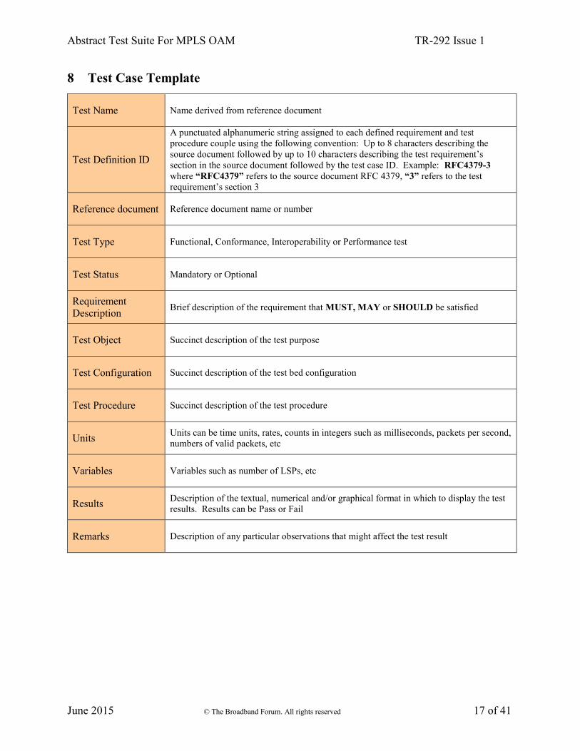
8 Test Case Template
Test Name Name derived from reference document
Test Definition ID
A punctuated alphanumeric string assigned to each defined requirement and test
procedure couple using the following convention: Up to 8 characters describing the
source document followed by up to 10 characters describing the test requirement’s
section in the source document followed by the test case ID. Example: RFC4379-3
where “RFC4379” refers to the source document RFC 4379, “3” refers to the test
requirement’s section 3
Reference document Reference document name or number
Test Type Functional, Conformance, Interoperability or Performance test
Test Status Mandatory or Optional
Requirement
Description Brief description of the requirement that MUST, MAY or SHOULD be satisfied
Test Object Succinct description of the test purpose
Test Configuration Succinct description of the test bed configuration
Test Procedure Succinct description of the test procedure
Units Units can be time units, rates, counts in integers such as milliseconds, packets per second,
numbers of valid packets, etc
Variables Variables such as number of LSPs, etc
Results Description of the textual, numerical and/or graphical format in which to display the test
results. Results can be Pass or Fail
Remarks Description of any particular observations that might affect the test result

Abstract Test Suite For MPLS OAM TR-292 Issue 1
June 2015 © The Broadband Forum. All rights reserved 18 of 41
9 Abstract Test Cases for MPLS OAM
9.1 OAM for MPLS LSP
Test Case 1: LSP Ping for LDP LSP with reply mode 2 (Reply via an IPv4 UDP packet)
Test Name LSP Ping for LDP LSP with reply mode 2 (Reply via an IPv4 UDP packet)
Test Definition ID TR221-5.2.1-1
Reference document TR221 and RFC 4379
Test Type Conformance
Test Status Mandatory if LDP is supported per Section 5.1.1 of TR-221.
Requirement
Description
According to R13 and R15 of TR221, when using LDP, LSP Ping MUST support replying
via an IPv4 UDP packet as Reply Mode (code value 2) and LDP IPv4 prefix in its FEC
Stack.
Note: Each LSP Ping test case serves as a validation test for the specific function the test
name shows, and also serves as a partial validation for R13 – general LSP Ping support. If
this test case fails, either this specific function or the general LSP Ping is not correctly
supported.
A sequence of LSP Ping echo request packets can be sent by DUT with a label stack
corresponding to the FEC Stack being tested.
When an LSP Ping echo request packet is received, an echo reply packet MUST be sent by
the DUT in response to the request.
LSP Ping echo request packets include the following elements: a label stack; an IP header; a
UDP header, and as the content of the UDP packet, an echo request message which carries a
Target FEC stack of LDP IPv4 prefix.
LSP Ping echo reply packets include the following elements: an IP header; a UDP header,
and as the content of the UDP packet, an echo reply message which carries a Target FEC
stack of LDP IPv4 prefix.
Test Object
Part A: Verify that an LSP Ping echo request packets include the following fields:
1. Label Stack: the label stack MUST include a top label value corresponding to the LSP,
and the TTL MUST be set to 255. Refer to Section 2.1 of RFC 4379.
2. IP header: the source IP address MUST be a routable address of the sender; the
destination IP address MUST be in the range 127/8; the IP TTL MUST be 1; and the IP
header MUST contain a Router Alert IP option. Refer to Section 4.3 of RFC 4379.
3. UDP header: the UDP destination port MUST be set to 3503. Refer to Section 4.3 of
RFC 4379.
4. Echo request message: Message Type value MUST be 1; TimeStamp Received MUST
be zero; Reply mode MUST be 2 (Reply via an IPv4 UDP packet). Refer to Section 4.3
of RFC 4379.
5. Target FEC stack: the target FEC stack must include an LDP IPv4 prefix (it MUST be
an LDP IPv4 prefix with sub-Type of 1 and Length of 5). Refer to Section 3.2 of RFC
4379.

Abstract Test Suite For MPLS OAM TR-292 Issue 1
June 2015 © The Broadband Forum. All rights reserved 19 of 41
Part B: Verify that LSP Ping echo reply packets include the following fields:
1. IP header: the source IP address MUST be a routable address of the replier; the
destination IP address MUST be equal to the source IP address of the echo request; the
IP TTL MUST be 255; and the IP header MUST contain a Router Alert IP option. Refer
to Section 4.5 of RFC 4379.
2. UDP header: the UDP source port MUST be set to 3503; the destination UDP port
MUST be equal to the source UDP port of the echo request. Refer to Section 4.5 of RFC
4379.
3. Echo reply message: Message Type value MUST be 2; the Sender's Handle, Sequence
Number, and TimeStamp Sent MUST be equal to those in the echo request. Refer to
Section 4.5 of RFC 4379.
Test Configuration Test configuration used per Figure 1 in Section 5, the DUT is PE1.
PE1 and PE2 are both configured with an IPv4 address and IPv4 prefix.
LSP Ping is configured to use LDP IPv4 prefix as its target FEC Stack on the DUT.
Test Procedure
1. Establish one unidirectional MPLS LSP for each direction using LDP between DUT
and PE2;
2. Use Test procedure 1 per Section 7.1.
Units LSP labels, echo request message, echo reply message, Target FEC sub TLV
Variables Number of LSPs
Results The test passes if all the verifications pass or else fails.
Remarks

Abstract Test Suite For MPLS OAM TR-292 Issue 1
June 2015 © The Broadband Forum. All rights reserved 20 of 41
Test Case 2: LSP Ping for RSVP-TE LSP using reply mode 2 (Reply via an IPv4 UDP
packet)
Test Name LSP Ping for RSVP-TE LSP using reply mode 2 (Reply via an IPv4 UDP packet)
Test Definition ID TR221-5.2.1-2
Reference document TR221 and RFC 4379
Test Type Conformance
Test Status Mandatory if RSVP-TE is supported per Section 5.1.1 of TR-221.
Requirement
Description
According to R13 and R15 of TR221, when using RSVP, LSP Ping MUST support replying via
an IPv4 UDP packet as Reply Mode (code value 2) and carrying RSVP IPv4 LSP in its FEC
Stack.
Note: Each LSP Ping test case serves as a validation test for the specific function the test name
shows, and also serves as a partial validation for R13 – general LSP Ping support. If this test
case fails, either this specific function or the general LSP Ping is not correctly supported.
A sequence of LSP Ping echo request packets can be sent by DUT with a label stack
corresponding to the FEC Stack being tested.
When an LSP Ping echo request packet is received, an echo reply packet MUST be sent by the
DUT in response to the request.
LSP Ping echo request packets include the following elements: a label stack; an IP header; a
UDP header, and as the content of the UDP packet, an echo request message which carries a
Target FEC stack of RSVP IPv4 LSP.
LSP Ping echo reply packets include the following elements: an IP header; a UDP header, and
as the content of the UDP packet, an echo reply message which carries a Target FEC stack of
RSVP IPv4 LSP.
Test Object
Part A: Verify that LSP Ping echo request packets include the fields specified in “Test
Case 1: LSP Ping for LDP LSP with reply mode 2 (Reply via an IPv4 UDP packet)” except
the following:
5. Target FEC stack: the target FEC stack must include an RSVP IPv4 LSP (it MUST be an
RSVP IPv4 LSP with sub-Type of 3 and Length of 20). Refer to Section 3.2 of RFC 4379.
Part B: Verify that LSP Ping echo reply packets include the fields specified in “Test Case
1: LSP Ping for LDP using reply mode 2 (Reply via an IPv4 UDP packet)”.
Test Configuration Test configuration used per Figure 1 in Section 5, the DUT is PE1.
PE1 and PE2 are both configured with an IPv4 address and IPv4 prefix.
LSP Ping is configured to use RSVP-TE IPv4 LSP as its target FEC Stack on the DUT.
Test Procedure
1. Establish one unidirectional MPLS LSP for each direction using RSVP-TE between PE1
and PE2;
2. Use Test procedure 1 per Section 7.1.
Units LSP labels, echo request message, echo reply message, Target FEC sub TLV
Variables Number of LSPs
Results The test passes if all the verifications pass or else fails
Remarks

Abstract Test Suite For MPLS OAM TR-292 Issue 1
June 2015 © The Broadband Forum. All rights reserved 21 of 41
Test Case 3: LSP Traceroute for LDP LSP using reply mode 2 (Reply via an IPv4 UDP
packet)
Test Name LSP Traceroute for LDP using reply mode 2 (Reply via an IPv4 UDP packet)
Test Definition ID TR221-5.2.1-3
Reference document TR221 and RFC4379
Test Type Conformance
Test Status Mandatory if LDP is supported per Section 5.1.1 of TR-221.
Requirement
Description
According to R14 and R15 of TR221, when using LDP, LSP Traceroute MUST support
replying via an IPv4 UDP packet as Reply Mode (code value 2) and LDP IPv4 prefix in its FEC
Stack.
Note: Each LSP Traceroute test case serves as a validation test for the specific function the test
name shows, and also serves as a partial validation for R14 - general LSP Traceroute support. If
this test case fails, either this specific function or the general LSP Traceroute is not correctly
supported.
A sequence of LSP Traceroute echo request packets can be sent by DUT with a label stack
corresponding to the FEC Stack being tested.
When an LSP Traceroute echo request packet is received, an echo reply packet MUST be sent
by the DUT in response to the request.
LSP Traceroute echo request packets include the following elements: a label stack; an IP
header; a UDP header, and as the content of the UDP packet, an echo request message which
carries a Target FEC stack of LDP IPv4 prefix.
LSP Traceroute echo reply packets include the following elements: an IP header; a UDP header,
and as the content of the UDP packet, an echo reply message which carries a Target FEC stack
of LDP IPv4 prefix.
Test Object
Part A: Verify that LSP Traceroute echo request packets include the following fields:
1. Label Stack: the label stack MUST include a top label value corresponding to the LSP, and
the TTL MUST be set successively to 1, and then 2. Refer to Section 4.3 of RFC 4379.
2. IP header: the source IP address MUST be a routable address of the sender; the destination
IP address MUST be in the range 127/8; the IP TTL MUST be 1; and the IP header MUST
contain a Router Alert IP option. Refer to Section 4.3 of RFC 4379.
3. UDP header: the UDP destination port MUST be set to 3503. Refer to Section 4.3 of RFC
4379.
4. Echo request message: Message Type value MUST be 1; TimeStamp Received MUST be
zero; Reply mode MUST be 2 (Reply via an IPv4 UDP packet). Refer to Section 4.3 of
RFC 4379.
5. Target FEC stack: the target FEC stack must include an LDP prefix (it MUST be an LDP
IPv4 prefix with sub-Type of 1 and Length of 5). Refer to Section 3.2.1 of RFC 4379.
Part B: Verify that LSP Traceroute echo reply packets include the following fields:
1. IP header: the source IP address MUST be a routable address of the replier; the destination
IP address MUST be equal to the source IP address of the echo request; the IP TTL MUST
be 255; and the IP header MUST contain a Router Alert IP option. Refer to Section 4.5 of

Abstract Test Suite For MPLS OAM TR-292 Issue 1
June 2015 © The Broadband Forum. All rights reserved 22 of 41
RFC 4379.
2. UDP header: the UDP source port MUST be set to 3503; the destination UDP port MUST
be equal to the source UDP port of the echo request. Refer to Section 4.5 of RFC 4379.
3. Echo reply message: Message Type value MUST be 2; the Sender's Handle, Sequence
Number, and TimeStamp Sent MUST be equal to those in the echo request. Refer to
Section 4.5 of RFC 4379.
Test Configuration Test configuration used per Figure 3 in Section 5, the DUT is PE1.
PE1 and PE2 are both configured with an IPv4 address and IPv4 prefix.
LSP Traceroute is configured to use LDP IPv4 prefix as its target FEC Stack on the DUT.
Test Procedure
1. Establish one unidirectional MPLS LSP for each direction using LDP between DUT and
PE2;
2. Use Test procedure 2 per Section 7.2.
Units LSP labels, echo request message, echo reply message, Target FEC sub TLV
Variables Number of LSPs
Results The test passes if all the verifications pass or else fails.
Remarks
Abstract Test Suite For MPLS OAM TR-292 Issue 1
June 2015 © The Broadband Forum. All rights reserved 23 of 41
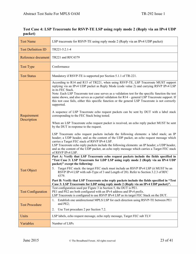
Test Case 4: LSP Traceroute for RSVP-TE LSP using reply mode 2 (Reply via an IPv4 UDP
packet)
Test Name LSP traceroute for RSVP-TE using reply mode 2 (Reply via an IPv4 UDP packet)
Test Definition ID TR221-5.2.1-4
Reference document TR221 and RFC4379
Test Type Conformance
Test Status Mandatory if RSVP-TE is supported per Section 5.1.1 of TR-221.
Requirement
Description
According to R14 and R15 of TR221, when using RSVP-TE, LSP Traceroute MUST support
replying via an IPv4 UDP packet as Reply Mode (code value 2) and carrying RSVP IPv4 LSP
in its FEC Stack.
Note: Each LSP Traceroute test case serves as a validation test for the specific function the test
name shows, and also serves as a partial validation for R14 – general LSP Traceroute support. If
this test case fails, either this specific function or the general LSP Traceroute is not correctly
supported.
A sequence of LSP Traceroute echo request packets can be sent by DUT with a label stack
corresponding to the FEC Stack being tested.
When an LSP Traceroute echo request packet is received, an echo reply packet MUST be sent
by the DUT in response to the request.
LSP Traceroute echo request packets include the following elements: a label stack; an IP
header; a UDP header, and as the content of the UDP packet, an echo request message which
carries a Target FEC stack of RSVP IPv4 LSP.
LSP Traceroute echo reply packets include the following elements: an IP header; a UDP header,
and as the content of the UDP packet, an echo reply message which carries a Target FEC stack
of RSVP IPv4 LSP.
Test Object
Part A: Verify that LSP Traceroute echo request packets include the fields specified in
“Test Case 3: LSP Traceroute for LDP LSP using reply mode 2 (Reply via an IPv4 UDP
packet)” except the following:
5. Target FEC stack: the target FEC stack must include an RSVP IPv4 LSP (it MUST be an
RSVP IPv4 LSP with sub-Type of 3 and Length of 20). Refer to Section 3.2.3 of RFC
4379.
Part B: Verify that LSP Traceroute echo reply packets include the fields specified in “Test
Case 3: LSP Traceroute for LDP using reply mode 2 (Reply via an IPv4 UDP packet)”.
Test Configuration Test configuration used per Figure 3 in Section 5, the DUT is PE1.
PE1 and PE2 are both configured with an IPv4 address and IPv4 prefix.
LSP Traceroute is configured to use RSVP IPv4 LSP as its target FEC Stack on the DUT.
Test Procedure
1. Establish one unidirectional MPLS LSP for each direction using RSVP-TE between PE1
and PE2;
2. Use Test procedure 2 per Section 7.2.
Units LSP labels, echo request message, echo reply message, Target FEC sub TLV
Variables Number of LSPs

Abstract Test Suite For MPLS OAM TR-292 Issue 1
June 2015 © The Broadband Forum. All rights reserved 24 of 41
Results The test passes if all the verifications pass or else fails
Remarks
Test Case 5: BFD Session Initialization using LSP Ping
Test Name BFD Session Initialization using LSP Ping
Test Definition ID TR221-5.2.1-5
Reference document TR221, RFC 5884
Test Type Conformance
Test Status Mandatory
Requirement
Description LSP Ping can bootstrap the BFD session correctly as per RFC 5884 (According to [R12] of
TR221, BFD for MPLS LSPs MUST be supported per RFC 5884).
Test Object
Part A: Verify that the BFD Discriminator TLV in the bootstrapping LSP Ping message
includes the following elements: LSP Ping TLV type value MUST be 15; The 4-byte value
field MUST be the local discriminator of the DUT. Refer to Section 6 of RFC 5884.
Part B: Verify that local BFD learns remote discriminator from the BFD Discriminator
TLV correctly: My Discriminator MUST be equal to the local discriminator of the originator
LSR. Refer to Section 6 of RFC 5884.
Your Discriminator MUST be equal to zero or the local discriminator of the target LSR. Refer
to Section 6 of RFC 5884.
Test Configuration Test configuration used per Figure 1 in Section 5, the DUT is PE1.
Test Procedure
1. Establish one unidirectional MPLS LSP for each direction between PE1 and PE2.
2. Use the CE Generator/Analyzer to generate services for encapsulation by the PEs. Use the
Protocol Analyzer to monitor traffic between PE1 and PE2.
3. Establish LSP Ping session between DUT and PE2, then establish BFD session between
DUT and PE2 in BFD asynchronous mode (refer to Sec.6 of RFC 5884), then
Part A:
Use the protocol analyzer to verify that LSP Ping echo request from DUT includes a BFD
discriminator TLV, and the TLV is correctly formatted according to Test Object Part A.
Part B:
Use the protocol analyzer to verify that Your Discriminator in the subsequent BFD packets
sent by DUT is the same as the value of BFD discriminator TLV in LSP Ping echo reply
sent from PE2.
Units LSP Ping echo request, LSP Ping echo reply, BFD Discriminator TLV
Variables Number of LSPs
Results The test passes if all the verifications pass or else fails.
Remarks

Abstract Test Suite For MPLS OAM TR-292 Issue 1
June 2015 © The Broadband Forum. All rights reserved 25 of 41
Test Case 6: BFD Fault Detection
Test Name BFD Fault Detection
Test Definition ID TR221-5.2.1-6
Reference document TR221, RFC 5880, RFC 5884
Test Type Conformance
Test Status Mandatory
Requirement
Description BFD can detect a data plane failure in the forwarding path of an MPLS LSP (According to
[R12] of TR221, BFD for MPLS LSPs MUST be supported per RFC 5884).
Test Object
Verify that a BFD packet includes the following fields:
1. Label Stack: the label stack MUST include a top label value corresponding to the LSP.
Refer to Section 7 of RFC 5884.
2. IP header: The IP TTL or hop limit MUST be set to 1; the source IP address MUST be a
routable address of the replier. Refer to Section 7 of RFC 5884.
3. UDP header: the UDP destination port MUST be 3784 or 4784. Refer to Section 7 of RFC
5884.
4. BFD message is encapsulated in the UDP payload. Refer to Section 7 of RFC 5884.
Verify that Dynamic BFD for LSP can detect fault correctly.
Test Configuration Test configuration used per Figure 1 in Section 5, the DUT is PE1.
Test Procedure
1. Establish two unidirectional LSPs from PE1 to PE2 and from PE2 to PE1 respectively.
2. Use the CE Generator/Analyzer to generate services for encapsulation by the PEs. Use the
Protocol Analyzer to monitor traffic between PE1 and PE2.
3. Establish BFD session between DUT and PE2 in BFD asynchronous mode, the state of
BFD session is UP, refer to Section 6 of RFC 5884.
4. Use the protocol analyzer to verify that BFD packets from DUT are formatted correctly
according to the test object.
5. Use the Protocol Analyzer to simulate a failure condition by blocking user traffic from PE2
to PE1 including BFD packets.
6. Verify that after failure condition above has been introduced, and after 5 times of BFD
cycle have passed, the state of BFD session on DUT migrates from UP to DOWN.
7. Remove the failure condition and ensure the BFD session comes back up after the failure.
Units BFD
Variables Number of LSPs, BFD cycle, Type of LSP and its FEC (LDP/RSVP-TE)
Results The test passes if all the verifications pass or else fails.
Remarks

Abstract Test Suite For MPLS OAM TR-292 Issue 1
June 2015 © The Broadband Forum. All rights reserved 26 of 41
9.2 OAM for PW
9.2.1 OAM for SS-PW
Test Case 7: BFD with VCCV using PW-ACH
Test Name BFD with VCCV using PW-ACH
Test Definition ID TR-221-5.2.3.1-1
Reference document TR-221, RFC5880, RFC5085, RFC5885, RFC5994
Test Type Conformance
Test Status Mandatory
Requirement
Description
According to R17 and R18 of TR221, For VCCV control channel type1, VCCV Profile1: BFD
without IP/UDP Headers MUST be supported and when the PW is established using static
provisioning, BFD status signaling using diagnostic codes per the VCCV profile1 SHOULD be
used.
The connection verification method used by VCCV is BFD with diagnostics as defined in
[RFC5885] (CV TYPE: 0x10/0x20). [RFC5085] specifies that the first nibble is set to 0x1 to
indicate a channel associated with a pseudowire(PW-ACH) in which the Version and the
Reserved fields are set to 0, and the Channel Type is set to 0x7 to indicate that the payload
carried is BFD without IP/UDP headers.
Test Object
Verify that a BFD for VCCV packet using PW-ACH includes the following fields:
1. Label Stack: Label stack include two labels, the top label value corresponding to an LSP
and the bottom label value corresponding to a PW. Refer to Section 3 of RFC 5885.
2. Generic Control Word: The first nibble is set to 0001b to indicate a channel associated with
a pseudowire. The Version and the Reserved fields are set to 0, and the Channel Type is set
to 0x7.
3. BFD message using diagnostic codes follows the Control Word directly.
Verify that BFD for VCCV without IP/UDP head for static PW can operate correctly.
Test Configuration Test configuration used per Figure1 in Section 5, the DUT is PE1.
Test Procedure
1. Establish one unidirectional LSP for each direction between PE1 and PE2, and establish at
least one static PW over this LSP.
2. Use the CE Generator/Analyzer to generate Ethernet services for encapsulation by the PEs.
Use the Protocol Analyzer to monitor traffic between DUT and PE2.
3. Configure BFD session for VCCV between DUT and PE2, verify that CV type is correct
and verify that BFD session is established successfully.
4. Use the protocol analyzer to verify that BFD packets from DUT are formatted correctly
according to the test object.
5. Use the Protocol Analyzer to simulate a failure condition by blocking user traffic from PE2

Abstract Test Suite For MPLS OAM TR-292 Issue 1
June 2015 © The Broadband Forum. All rights reserved 27 of 41
to DUT including BFD packets.
6. Verify that in the above failure condition, after 5 times of BFD cycle, the state of BFD
session on DUT migrates from UP to DOWN.
Units LSP label, PW label, Target FEC sub TLV
Variables Number of LSPs, BFD cycle, Type of CV (0x10 for Fault Detection Only or 0x20 for Fault
Detection and Status Signaling)
Results The test passes if all the verifications pass or else fails.
Remarks
Test Case 8: BFD with VCCV for static PW (with IPv4 UDP headers)
Test Name BFD with VCCV for static PW (with IPv4 UDP headers)
Test Definition ID TR221-5.2.3.1-2
Reference document TR221, RFC5880, RFC5085, RFC5885, RFC5994
Test Type Conformance
Test Status Optional
Requirement
Description
According to R17 and R18 of TR221, BFD is one of the connection verification method used by
VCCV.
When the PW is established using static provisioning, BFD status signaling using diagnostic
codes per the VCCV profile supported SHOULD be used for fault notification.
Test Object
Verify that a BFD for VCCV packet includes the following fields:
1. Label Stack: Label stack include two labels, the top label value corresponding to an LSP
and the bottom label value corresponding to a PW. Refer to Section 3 of RFC 5885.
2. Generic Control Word: The first nibble is set to 0001b to indicate a channel associated with
a pseudowire. The Version and the Reserved fields are set to 0, and the Channel Type is set
to 0x0021 for IPv4 payloads. Refer to Section 3 of RFC 5885.
3. The IP header: The source IP address MUST be an address of the sender; the destination IP
address is a (randomly chosen) IPv4 address from the range 127/8. Refer to Section 3 of
RFC 5885.
4. UDP header: The UDP destination port MUST be 3784 and source port MUST be within
the range 49152 through 65535. Refer to Section 3 of RFC 5885.
5. BFD message is encapsulated in the UDP payload. Refer to Section 4 of RFC 5880. Where
CV type MUST be either 0x04 or 0x08, both stand for IP/UDP encapsulation.
Verify that BFD for VCCV with IPv4 UDP header for static PW can operate correctly.
Test Configuration Test configuration used per Figure1 in Section 5, the DUT is PE1.

Abstract Test Suite For MPLS OAM TR-292 Issue 1
June 2015 © The Broadband Forum. All rights reserved 28 of 41
Test Procedure
1. Establish one unidirectional LSP for each direction between PE1 and PE2,and establish at
least one static PW over this LSP.
2. Use the CE Generator/Analyzer to generate Ethernet services for encapsulation by the PEs.
Use the Protocol Analyzer to monitor traffic between DUT and PE2.
3. Configure BFD session for VCCV between DUT and PE2, verify that the CV type is
correct and BFD session is established successfully.
4. Use the protocol analyzer to verify that BFD packets from DUT are formatted correctly
according to the test object.
5. Use the Protocol Analyzer to simulate a failure condition by blocking user traffic from PE2
to DUT including BFD packets.
6. Verify that in the above failure condition, after 5 times of BFD cycle, the state of BFD
session on DUT migrates from UP to DOWN, and the PW failure is reported correctly.
Units LSP label, PW label, Target FEC sub TLV
Variables Number of PWs, BFD cycle, Type of CV (0x04 for Fault Detection Only or 0x08 for Fault
Detection and Status Signaling)
Results The test passes if all the verifications pass or else fails.
Remarks

Abstract Test Suite For MPLS OAM TR-292 Issue 1
June 2015 © The Broadband Forum. All rights reserved 29 of 41
Test Case 9: BFD with VCCV using PW-ACH for LDP signaled PW (without IP/UDP
headers)
Test Name BFD with VCCV using PW-ACH for LDP signaled PW (without IP/UDP headers)
Test Definition ID TR221-5.2.3.1-3
Reference document TR221, RFC5880, RFC5085, RFC5885, RFC5994, RFC6310
Test Type Conformance
Test Status Mandatory if LDP is supported
Requirement
Description
According to R17 and R19 of TR221, when LDP is supported for PW establishment, for VCCV
control channel type 1, VCCV Profile1: BFD without IP/UDP Headers MUST be supported,
and fault notification MUST be supported per RFC6310 by PE routers.
The connection verification method used by VCCV is BFD with diagnostics as defined in
[RFC5885] (CV TYPE: 0x10). [RFC5085] specifies that the first nibble is set to 0x1 to indicate
a channel associated with a pseudowire (PW-ACH) in which the Version and the Reserved
fields are set to 0, and the Channel Type is set to 0x7 to indicate that the payload carried is BFD
without IP/UDP headers.
Test Object
Verify that a BFD for VCCV packet includes the following fields:
1. Label Stack: Label stack include two labels, the top label value corresponding to an LSP
and the bottom label value corresponding to a PW. Refer to Section 3 of RFC 5885.
2. Generic Control Word: The first nibble is set to 0001b to indicate a channel associated with
a pseudowire. The Version and the Reserved fields are set to 0, and the Channel Type is set
to 0x0007. Refer to Section 3 of RFC 5885.
3. BFD message using diagnostic codes follows the Control Word directly. Refer to Section 3
of RFC 5885.
Verify that BFD for VCCV for LDP signaled PW can operate correctly.
Test Configuration Test configuration used per Figure1 in Section 5, the DUT is PE1.
Test Procedure
1. Establish one unidirectional LSP for each direction between PE1 and PE2, and establish at
least one PW using LDP over this LSP.
2. Use the CE Generator/Analyzer to generate Ethernet services for encapsulation by the PEs.
Use the Protocol Analyzer to monitor traffic between DUT and PE2.
3. Configure BFD session for VCCV between DUT and PE2, verify that the CV type is 0x10
and BFD session is established successfully.
4. Use the protocol analyzer to verify that BFD packets from DUT are formatted correctly
according to the test object.
5. Use the Protocol Analyzer to simulate a failure condition by blocking user traffic from PE2
to DUT including BFD packets.
6. Verify that in the above failure condition, after 5 times of BFD cycle, the state of BFD
session on DUT migrates from UP to DOWN.
Units LSP label, PW label, Target FEC sub TLV
Variables Number of PWs, BFD cycle, Type of CV
Results The test passes if all the verifications pass or else fails.
Remarks

Abstract Test Suite For MPLS OAM TR-292 Issue 1
June 2015 © The Broadband Forum. All rights reserved 30 of 41
Test Case 10: BFD with VCCV for LDP signaled PW (with IPv4/UDP headers)
Test Name BFD with VCCV using PW-ACH for LDP signaled PW (with IPv4/UDP headers)
Test Definition ID TR221-5.2.3.1-4
Reference document TR221, RFC5880, RFC5085, RFC5885, RFC5994
Test Type Conformance
Test Status Optional
Requirement
Description
According to R17 and R19 of TR221, BFD is one of the connection verification method used by
VCCV.
When LDP is supported for PW establishment, BFD status signaling using diagnostic codes per
the VCCV profile 2 SHOULD be used for fault notification.
Test Object
Verify that a BFD for VCCV packet includes the following fields:
1. Label Stack: Label stack include two labels, the top label value corresponding to an LSP
and the bottom label value corresponding to a PW. Refer to Section 3 of RFC 5885.
2. Generic Control Word: The first nibble is set to 0001b to indicate a channel associated with
a pseudowire. The Version and the Reserved fields are set to 0, and the Channel Type is set
to 0x0021 for IPv4 payloads. Refer to Section 3 of RFC 5885.
3. The IP header: The source IP address MUST be an address of the sender; the destination IP
address is a (randomly chosen) IPv4 address from the range 127/8. Refer to Section 3 of
RFC 5885.
4. UDP header: The UDP destination port MUST be 3784 and source port MUST be within
the range 49152 through 65535. Refer to Section 3 of RFC 5885.
5. BFD message is encapsulated in the UDP payload. Refer to Section 4 of RFC 5880. Where
CV type MUST be 0x04, which stands for IP/UDP encapsulation for PW Fault Detection
only.
Verify that BFD for VCCV with IPv4 UDP header for LDP based PW can operate
correctly.
Test Configuration Test configuration used per Figure1 in Section 5, the DUT is PE1.
Test Procedure
1. Establish one unidirectional LSP for each direction between PE1 and PE2, and establish at
least one PW using LDP over this LSP.
2. Use the CE Generator/Analyzer to generate Ethernet services for encapsulation by the PEs.
Use the Protocol Analyzer to monitor traffic between DUT and PE2.
3. Configure BFD session for VCCV between DUT and PE2, verify that the CV type is 0x04
and BFD session is established successfully.
4. Use the protocol analyzer to verify that BFD packets from DUT are formatted correctly
according to the test object.
5. Use the Protocol Analyzer to simulate a failure condition by blocking user traffic from PE2
to DUT including BFD packets.
6. Verify that in the above failure condition, after 5 times of BFD cycle, the state of BFD
session on DUT migrates from UP to DOWN.
Units LSP label, PW label, Target FEC sub TLV
Abstract Test Suite For MPLS OAM TR-292 Issue 1
June 2015 © The Broadband Forum. All rights reserved 31 of 41
Variables Number of PWs, BFD cycle, Type of CV
Results The test passes if all the verifications pass or else fails.
Remarks
Test Case 11: VCCV LSP Ping using PW-ACH
Test Name VCCV LSP Ping using PW-ACH
Test Definition ID TR-221-5.2.3.1-5
Reference document TR-221
Test Type Conformance
Test Status Mandatory
Requirement
Description
According to R16 and R20 of TR221, VCCV Control Channel (CC) Type1, also known as
"PWE3 Control Word with 0001b as first nibble", MUST be supported. MPLS LSP Ping (CV
type 0x02) SHOULD be supported per RFC 5085.
When the control channel for the PW is chosen as "PWE3 Control Word with 0001b as first
nibble" (use the PW Associated Channel Header), VCCV LSP Ping packets are sent over the
PW together with in-band data traffic.
VCCV messages with CC Type1 and CV type (0x02) include the following elements: a label
stack; a generic Control Word; an LSP Ping header; Target FEC stack.
Test Object
Part A: Verify that VCCV LSP Ping echo request packets include the following fields:
1. Label Stack: the label stack MUST include a top label value corresponding to an LSP,
and the TTL MUST be set to 255, and a bottom label value corresponding to a PW. Refer
to Section 2.1 of RFC 4379.
2. PW Associated Channel Header:the first nibble is set to 0001b to indicate a channel
associated with a pseudowire. The Version and the Reserved fields are set to 0, and the
Channel Type is set to 0x0021 for IPv4 payloads.
3. IP header and UDP header are set in accordance with the corresponding fields in LSP
Ping test case 1.
4. Target FEC stack: containing the sub-TLV of sub-Type 10 for "FEC 128 Pseudowire",
or 11 for the "FEC 129 Pseudowire".
Part B: Verify that VCCV LSP ping using PW-ACH operates correctly in verifying
connectivity of the PW and the data plane used to transport the data path for the PW and
that VCCV LSP Ping echo reply packets include the following fields:
1. Label Stack: the label stack MUST include a top label value corresponding to an LSP,
and the TTL MUST be set to 255, and a bottom label value corresponding to a PW. Refer
to Section 2.1 of RFC 4379.
2. PW Associated Channel Header: the first nibble is set to 0001b to indicate a channel
associated with a PW. The Version and the Reserved fields are set to 0, and the Channel
Type is set to 0x0021 for IPv4 payloads.

Abstract Test Suite For MPLS OAM TR-292 Issue 1
June 2015 © The Broadband Forum. All rights reserved 32 of 41
3. IP header and UDP header are set in accordance with the corresponding fields in LSP
Ping test case 1.
4. Target FEC stack format: containing the sub-TLV of sub-Type 10 for "FEC 128
Pseudowire", or 11 for the "FEC 129 Pseudowire".
Test Configuration Test configuration used per Figure 1 in Section 5, the DUT is PE1.
Test Procedure
1. Establish one unidirectional LSP for each direction between PE1 and PE2, and establish at
least one PW over this LSP. The PW is configured to support CC type 1 (PWE3 Control
Word with 0001b as first nibble) and CV type 0x02 (LSP Ping);
2. Use the CE Generator/Analyzer to generate services for encapsulation by the PEs and use
the Protocol Analyzer to monitor traffic between DUT and PE2:
Part A:
Start VCCV LSP ping on DUT on control channel that is associated with the established
PW.
Use the protocol analyzer to verify that the VCCV message (including LSP Ping echo
request) is correctly formatted according to Test Object Part A.
Part B:
Start VCCV LSP ping on DUT on control channel that is associated with the established
PW.
Verify that a VCCV message (including LSP Ping echo request) reaches DUT and triggers
a VCCV message (including LSP Ping echo reply) from DUT and use the protocol analyzer
to verify that the VCCV message (including LSP Ping echo reply) is correctly formatted
according to Test Object Part B.
Units LSP label, PW label, Target FEC sub TLV
Variables PW type (FEC 128 or 129), PW type (the PW could be statically configured or established by
LDP signaling).
Results The test passes if all the verifications pass or else fails.
Remarks

Abstract Test Suite For MPLS OAM TR-292 Issue 1
June 2015 © The Broadband Forum. All rights reserved 33 of 41
9.2.2 OAM for MS-PW
Test Case 12: MS-PW E2E Connectivity Verification using VCCV Ping (In-Band VCCV)
Test Name MS-PW end to end Connectivity Verification using VCCV Ping (In-Band VCCV)
Test Definition ID TR-221-5.2.3.2-1
Reference document TR-221, RFC4379, RFC5085, RFC6073
Test Type Conformance
Test Status Optional
Requirement
Description
According to R22 of TR221, if MS-PW is supported, End-to-end MS-PW connectivity
verification SHOULD be supported using VCCV connectivity verification (Ping).
This operation enables the connectivity of the MS-PW to be tested from source T-PE to
destination T-PE. In order to do this, the sending T-PE must include the FEC used in the last
segment of the MS-PW to the destination T-PE in the VCCV-Ping echo request.
Upon receiving a VCCV-Ping echo request, the destination T-PE responds to the echo request
with an echo reply with a return code of 3 (Egress Router).
Test Object
Part A: Verify that VCCV LSP Ping echo request packets include the following fields:
1. Label Stack: the label stack MUST include a top label value corresponding to an LSP, the
TTL MUST be set to 255, and a bottom label value corresponding to a PW, the TTL can be
set to any value that is sufficient for the packet to reach the destination T-PE.
2. PW Associated Channel Header: the first nibble is set to 0001b to indicate a channel
associated with a pseudowire. The Version and the Reserved fields are set to 0, and the
Channel Type is set to 0x0021 for IPv4 payloads.
3. IP header and UDP header are set in accordance with the corresponding fields in LSP Ping
test case 1.
4. Target FEC stack: it MAY include the FEC (sub-Type 10 for "FEC 128 Pseudowire", or 11
for the "FEC 129 Pseudowire") used in the last segment of the MS-PW to the destination T-
PE.
Part B: Verify that VCCV LSP Ping echo reply packets include the following fields:
1. Label Stack: the label stack MUST include a top label value corresponding to an LSP, the
TTL MUST be set to 255, and a bottom label value corresponding to a PW, the TTL can be
set to any value that is sufficient for the packet to reach the destination T-PE.
2. PW Associated Channel Header: the first nibble is set to 0001b to indicate a channel
associated with a PW. The Version and the Reserved fields are set to 0, and the Channel
Type is set to 0x0021 for IPv4 payloads.
3. IP header and UDP header are set in accordance with the corresponding fields in LSP Ping
test case 1.
4. Target FEC stack format: it MAY include the FEC (sub-Type 10 for "FEC 128
Pseudowire", or 11 for the "FEC 129 Pseudowire") used in the last segment of the MS-PW
to the destination T-PE.
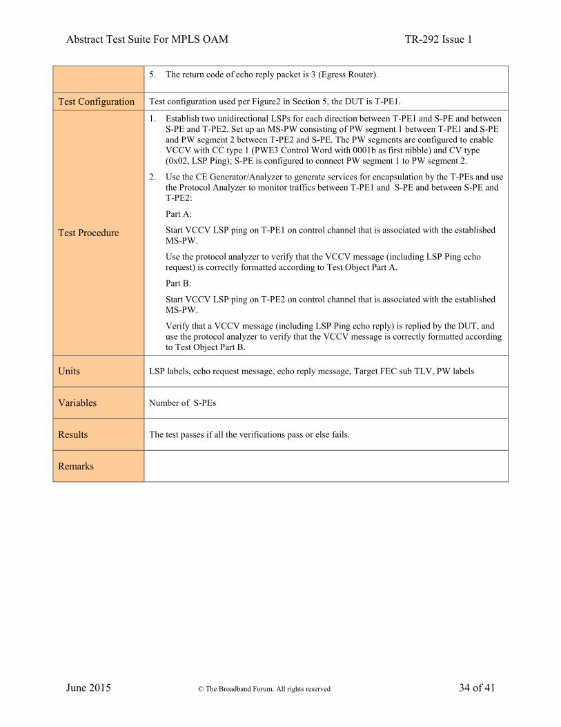
Abstract Test Suite For MPLS OAM TR-292 Issue 1
June 2015 © The Broadband Forum. All rights reserved 34 of 41
5. The return code of echo reply packet is 3 (Egress Router).
Test Configuration Test configuration used per Figure2 in Section 5, the DUT is T-PE1.
Test Procedure
1. Establish two unidirectional LSPs for each direction between T-PE1 and S-PE and between
S-PE and T-PE2. Set up an MS-PW consisting of PW segment 1 between T-PE1 and S-PE
and PW segment 2 between T-PE2 and S-PE. The PW segments are configured to enable
VCCV with CC type 1 (PWE3 Control Word with 0001b as first nibble) and CV type
(0x02, LSP Ping); S-PE is configured to connect PW segment 1 to PW segment 2.
2. Use the CE Generator/Analyzer to generate services for encapsulation by the T-PEs and use
the Protocol Analyzer to monitor traffics between T-PE1 and S-PE and between S-PE and
T-PE2:
Part A:
Start VCCV LSP ping on T-PE1 on control channel that is associated with the established
MS-PW.
Use the protocol analyzer to verify that the VCCV message (including LSP Ping echo
request) is correctly formatted according to Test Object Part A.
Part B:
Start VCCV LSP ping on T-PE2 on control channel that is associated with the established
MS-PW.
Verify that a VCCV message (including LSP Ping echo reply) is replied by the DUT, and
use the protocol analyzer to verify that the VCCV message is correctly formatted according
to Test Object Part B.
Units LSP labels, echo request message, echo reply message, Target FEC sub TLV, PW labels
Variables Number of S-PEs
Results The test passes if all the verifications pass or else fails.
Remarks

Abstract Test Suite For MPLS OAM TR-292 Issue 1
June 2015 © The Broadband Forum. All rights reserved 35 of 41
Test Case 13: MS-PW partial Connectivity Verification using VCCV Ping (TTL Expiry
VCCV)
Test Name MS-PW partial Connectivity Verification using VCCV Ping (TTL Expiry VCCV)
Test Definition ID TR-221-5.2.3.2-2
Reference document TR-221, RFC4379, RFC5085, RFC6073
Test Type Conformance
Test Status Optional
Requirement
Description
According to R23 of TR221, if MS-PW is supported, partial MS-PW connectivity verification
SHOULD be supported using VCCV connectivity verification (Ping).
This operation verifies the connectivity of a segment of an MS-PW to be tested between the
source T-PE and an S-PE. The FEC used on the last segment to be tested must be included in
the VCCV-Ping echo request message.
Test Object
Part A: Verify that VCCV LSP Ping echo request packets include the following fields:
1. Label Stack: the label stack MUST include a top label value corresponding to an LSP, the
TTL MUST be set to 255, and a bottom label value corresponding to a PW, the TTL should
be set to the exact value to allow the packet to reach the destination S-PE.
2. IP header and UDP header are set in accordance with the corresponding fields in LSP Ping
test case 1.
3. Target FEC stack: it MUST include the FEC (sub-Type 10 for "FEC 128 Pseudowire", or
11 for the "FEC 129 Pseudowire") used in the last segment of the MS-PW.
Part B: Verify that VCCV LSP Ping echo reply packets include the following fields:
1. Label Stack: the label stack MUST include a top label value corresponding to an LSP, the
TTL MUST be set to 255, and a bottom label value corresponding to a PW, the TTL should
be set to the exact value to allow the packet to reach the destination S-PE.
2. IP header and UDP header are set in accordance with the corresponding fields in LSP Ping
test case 1.
3. Target FEC stack format: it MUST contain the FEC (sub-Type 10 for "FEC 128
Pseudowire", or 11 for the "FEC 129 Pseudowire") used in the last segment of the MS-PW.
Test Configuration Test configuration used per Figure2 in Section 5, the DUT is T-PE1.
Test Procedure
1. Establish two unidirectional LSPs for each direction between T-PE1 and S-PE and between
S-PE and T-PE2. Set up an MS-PW consisting of PW segment 1 between T-PE1 and S-PE
and PW segment 2 between T-PE2 and S-PE. The PW segments are configured to enable
VCCV with CC type 3 (TTL Expiry VCCV) and CV type 0x02 (LSP Ping); S-PE is
configured to connect PW segment 1 to PW segment 2.
2. Use the CE Generator/Analyzer to generate services for encapsulation by the T-PEs and use
the Protocol Analyzer to monitor the packet flow between T-PE1 and S-PE:
Part A:
Start VCCV LSP ping on T-PE1 on control channel that is associated with the established
MS-PW, PW label TTL is set to 1 to force the VCCV packet to be processed at S-PE.
Use the protocol analyzer to verify that the VCCV message (including LSP Ping echo

Abstract Test Suite For MPLS OAM TR-292 Issue 1
June 2015 © The Broadband Forum. All rights reserved 36 of 41
request) is correctly formatted according to Test Object Part A.
Part B:
Start VCCV LSP ping on S-PE on control channel that is associated with the established
MS-PW, PW label TTL is set to 1 to force the VCCV packet to be processed at T-PE1.
Use the protocol analyzer to verify that a VCCV message (including LSP Ping echo reply)
is replied by T-PE1, and the message is correctly formatted according to Test Object Part
B.
Units LSP labels, echo request message, echo reply message, Target FEC sub TLV, PW labels
Variables
Results The test passes if all the verifications pass or else fails.
Remarks

Abstract Test Suite For MPLS OAM TR-292 Issue 1
June 2015 © The Broadband Forum. All rights reserved 37 of 41
Test Case 14: Including FEC 129 Sub-TLV in SP-PE TLV by an S-PE
Test Name Including FEC 129 Sub-TLV in SP-PE TLV by an S-PE
Test Definition ID TR-221-5.2.3.2-3
Reference document TR-221C1, RFC4379, RFC5085, RFC6073
Test Type Conformance
Test Status Optional, applicable if FEC 129 is used in PW signaling
Requirement
Description
According to [R-25a] of TR-221C1, the S-PE MUST support including the FEC 129 of the last
PW segment in the Pseudowire Switching Point PE sub-TLV as per the FEC 129 encoding in
Section 7.4.1/RFC6073 when LDP FEC 129 is used to signal the PW.
According to [R-25b] of TR-221C1, the S-PE MUST support including FEC 129 in the Target
FEC stack TLV in the VCCV echo reply message as per the FEC 129 encoding in Section
3.2.10/RFC 4379.
Test Object
Part A: Verify that MS-PW LDP mapping message includes the following fields:
1. SP-PE TLV: the “U” bit MUST be set for backward compatibility and Sub-TLV Type
MUST be encoded as 0x096D.
2. FEC sub-TLV of last PW segment traversed: Type is encoded as 0x05. The FEC element of
the last PW segment traversed MUST be in accordance with the FEC 129 encoding in
Section 7.4.1/RFC6073.
Part B: Verify that VCCV LSP Ping (PW-ACH) operates correctly using the FEC
obtained by processing the FEC 129 sub-TLV of the optional SP-PE TLV.
Test Configuration Test configuration used per Figure2 in Section 5, the DUT is S-PE.
Test Procedure
1. Establish two unidirectional LSPs for each direction between T-PE1 and S-PE and between
S-PE and T-PE2. Set up an MS-PW consisting of PW segment 1 between T-PE1 and S-PE
and PW segment 2 between T-PE2 and S-PE using the generalized FEC 129. The PW
segments are configured to enable VCCV with CC type 1 (PWE3 Control Word with
0001b as first nibble) and CV type 0x02 (LSP Ping); S-PE is configured to connect PW
segment 1 to PW segment 2.
2. Use the CE Generator/Analyzer to generate services for encapsulation by the T-PEs and use
the Protocol Analyzer to monitor traffics between T-PE1 and S-PE and between S-PE and
T-PE2:
Part A:
Initiate MS-PW setup via dynamic LDP control plane using the generalized FEC 129.
Use the protocol analyzer to verify that the SP-PE TLV included into the LDP mapping
message by S-PE is correctly formatted according to Test Object Part A.
Part B:
Start VCCV LSP ping on T-PE1 on control channel that is associated with the established
MS-PW.
Use the protocol analyzer to verify that the FEC stack in VCCV message is consistent with
FEC 129 according to Test Object Part B.
Units SP-PE TLV, FEC 129 sub TLV

Abstract Test Suite For MPLS OAM TR-292 Issue 1
June 2015 © The Broadband Forum. All rights reserved 38 of 41
Variables
Results The test passes if all the verifications pass or else fails.
Remarks

Abstract Test Suite For MPLS OAM TR-292 Issue 1
June 2015 © The Broadband Forum. All rights reserved 39 of 41
9.3 Packet Loss & Delay Measurement for LSP/PW
Test Case 15: Packet loss measurement for LSP/PW
Test Name Packet loss measurement for LSP/PW
Test Definition ID TR221-5.2.4-1
Reference document TR221 and RFC 6374
Test Type Performance Monitoring and Measurement
Test Status Mandatory if loss measurement is supported
Requirement
Description According to R28 of TR221, PE and P routers SHOULD support packet loss measurement per
RFC 6374.
Test Object 1. PE and P should properly give the accurate result of LM.
Test Configuration Test configuration used per Figure1 in Section 5, the DUT is PE1.
Test Procedure
1. Establish at least one MPLS LSP/PW tunnel between PE1 and PE2.
2. Use the CE Generator/Analyzer to generate services for encapsulation by the PEs, and use
the Protocol Analyzer to monitor the traffic between PE1 and PE2. The Network Analyzer
should be configured to work in pass through mode.
3. Start LM measurement on PE1 and PE2. The packet loss should be 0.
4. Verify the LM query message and response message are correctly formatted.
5. Use the Protocol Analyzer to insert a packet loss rate. To reduce the probability of losing a
single measurement probe, the measurement probe should be sent multiple times.
6. Compare the LM result executed on PEs with packet loss rate inserted into the traffic and
packet loss rate monitored by CE Generator/Analyzer to estimate the accuracy of LM.
Units LSP labels, LM query message, response message
Variables Packet loss rate
Results Pass or fail
Remarks

Abstract Test Suite For MPLS OAM TR-292 Issue 1
June 2015 © The Broadband Forum. All rights reserved 40 of 41
Test Case 16: Delay measurement for LSP/PW
Test Name Delay measurement (two way) for LSP/PW
Test Definition ID TR221-5.2.4-2
Reference document TR221 and RFC 6374
Test Type Performance Monitoring and Measurement
Test Status Mandatory if delay measurement is supported
Requirement
Description According to R28 of TR221, PE and P routers SHOULD support Delay measurement per RFC
6374.
Test Object 1. PE and P should properly give the accurate result of DM.
Test Configuration Test configuration used per Figure1 in Section 5, the DUT is PE1.
Test Procedure
1. Establish at least one MPLS LSP/PW tunnel between PE1 and PE2.
2. Use the CE Generator/Analyzer to generate services for encapsulation by the PEs, and use
the Protocol Analyzer to monitor the traffic between PE1 and PE2. The Network Analyzer
should be configured to work in pass through mode.
3. Start DM measurement on PE1 and PE2.
4. Verify the DM query message and response message are correctly formatted.
5. Use the Protocol Analyzer to insert delay into traffic, labeled as T.
6. Start DM measurement on PE1 and PE2. The delay results are labeled as T1and T2
respectively.
7. Use the Protocol Analyzer to insert another delay into traffic, labeled as T’.
8. Start DM measurement on PE1 and PE2. The delay results are labeled as T1’and T2’
respectively.
9. Compare the (T’ -T) with (T1’-T1) and (T2’ –T2) to estimate the consistency of DM.
Units LSP labels, DM query message, response message
Variables Time delay
Results Pass or fail
Remarks

Abstract Test Suite For MPLS OAM TR-292 Issue 1
June 2015 © The Broadband Forum. All rights reserved 41 of 41
End of Broadband Forum Technical Report TR-292