above nema duty master ac motors - global industrial
TRANSCRIPT

Above NEMA Duty Master AC MotorsFrames: 5000, 5800, 6800, 7111, 9000,
G315, G400, G500Enclosures: Open and Totally Enclosed
Mounting: Horizontal and Vertical
Installation & Operating Manual
8/12 MN420

Any trademarks used in this manual are the property of their respective owners.
Be sure to check www.baldor.com for the latest version of this manual in Adobe Acrobat PDF format.

Table of Contents
Table of Contents iMN420
Section 1General Information 1-1. . . . . . . . . . . . . . . . . . . . . . . . . . . . . . . . . . . . . . . . . . . . . . . . . . . . . . . . . . . . . . . . . . . . . . . . . . . . . . .
Overview 1-1. . . . . . . . . . . . . . . . . . . . . . . . . . . . . . . . . . . . . . . . . . . . . . . . . . . . . . . . . . . . . . . . . . . . . . . . . . . . . . . . . . . . .
Safety Notice 1-1. . . . . . . . . . . . . . . . . . . . . . . . . . . . . . . . . . . . . . . . . . . . . . . . . . . . . . . . . . . . . . . . . . . . . . . . . . . . . . . . . .
Receiving 1-3. . . . . . . . . . . . . . . . . . . . . . . . . . . . . . . . . . . . . . . . . . . . . . . . . . . . . . . . . . . . . . . . . . . . . . . . . . . . . . . . . . . . .
Handling 1-3. . . . . . . . . . . . . . . . . . . . . . . . . . . . . . . . . . . . . . . . . . . . . . . . . . . . . . . . . . . . . . . . . . . . . . . . . . . . . . . . . . . . . .
Storage 1-4. . . . . . . . . . . . . . . . . . . . . . . . . . . . . . . . . . . . . . . . . . . . . . . . . . . . . . . . . . . . . . . . . . . . . . . . . . . . . . . . . . . . . . .
Unpacking 1-4. . . . . . . . . . . . . . . . . . . . . . . . . . . . . . . . . . . . . . . . . . . . . . . . . . . . . . . . . . . . . . . . . . . . . . . . . . . . . . . . . . . .
Section 2Installation & Operation 2-1. . . . . . . . . . . . . . . . . . . . . . . . . . . . . . . . . . . . . . . . . . . . . . . . . . . . . . . . . . . . . . . . . . . . . . . . . . .
Overview 2-1. . . . . . . . . . . . . . . . . . . . . . . . . . . . . . . . . . . . . . . . . . . . . . . . . . . . . . . . . . . . . . . . . . . . . . . . . . . . . . . . . . . . .
Location 2-1. . . . . . . . . . . . . . . . . . . . . . . . . . . . . . . . . . . . . . . . . . . . . . . . . . . . . . . . . . . . . . . . . . . . . . . . . . . . . . . . . . . . . .
Foundation 2-1. . . . . . . . . . . . . . . . . . . . . . . . . . . . . . . . . . . . . . . . . . . . . . . . . . . . . . . . . . . . . . . . . . . . . . . . . . . . . . . . . . . .
Pre Installation Checks 2-2. . . . . . . . . . . . . . . . . . . . . . . . . . . . . . . . . . . . . . . . . . . . . . . . . . . . . . . . . . . . . . . . . . . . . . . . .
Doweling & Bolting 2-2. . . . . . . . . . . . . . . . . . . . . . . . . . . . . . . . . . . . . . . . . . . . . . . . . . . . . . . . . . . . . . . . . . . . . . . . . . . . .
Coupling 2-3. . . . . . . . . . . . . . . . . . . . . . . . . . . . . . . . . . . . . . . . . . . . . . . . . . . . . . . . . . . . . . . . . . . . . . . . . . . . . . . . . . . . . .
Grouting 2-4. . . . . . . . . . . . . . . . . . . . . . . . . . . . . . . . . . . . . . . . . . . . . . . . . . . . . . . . . . . . . . . . . . . . . . . . . . . . . . . . . . . . . .
Lubrication 2-4. . . . . . . . . . . . . . . . . . . . . . . . . . . . . . . . . . . . . . . . . . . . . . . . . . . . . . . . . . . . . . . . . . . . . . . . . . . . . . . . . . . .
Anti Friction Bearings (Grease Lubricated) 2-4. . . . . . . . . . . . . . . . . . . . . . . . . . . . . . . . . . . . . . . . . . . . . . . . . . . .
Sleeve Bearing (Oil Lubricated) 2-4. . . . . . . . . . . . . . . . . . . . . . . . . . . . . . . . . . . . . . . . . . . . . . . . . . . . . . . . . . . . . .
Electrical Connection 2-4. . . . . . . . . . . . . . . . . . . . . . . . . . . . . . . . . . . . . . . . . . . . . . . . . . . . . . . . . . . . . . . . . . . . . . . . . . .
Grounding 2-5. . . . . . . . . . . . . . . . . . . . . . . . . . . . . . . . . . . . . . . . . . . . . . . . . . . . . . . . . . . . . . . . . . . . . . . . . . . . . . . . . . . .
Pre−Operation Check 2-6. . . . . . . . . . . . . . . . . . . . . . . . . . . . . . . . . . . . . . . . . . . . . . . . . . . . . . . . . . . . . . . . . . . . . . . . . .
First Time Uncoupled Start−Up 2-6. . . . . . . . . . . . . . . . . . . . . . . . . . . . . . . . . . . . . . . . . . . . . . . . . . . . . . . . . . . . . . . . . .
Coupled Start−up 2-7. . . . . . . . . . . . . . . . . . . . . . . . . . . . . . . . . . . . . . . . . . . . . . . . . . . . . . . . . . . . . . . . . . . . . . . . . . . . . .
Jogging and Repeated Starts 2-7. . . . . . . . . . . . . . . . . . . . . . . . . . . . . . . . . . . . . . . . . . . . . . . . . . . . . . . . . . . . . . . . . . . .
Section 3Maintenance & Troubleshooting 3-1. . . . . . . . . . . . . . . . . . . . . . . . . . . . . . . . . . . . . . . . . . . . . . . . . . . . . . . . . . . . . . . . . . . .
Periodic Inspection 3-1. . . . . . . . . . . . . . . . . . . . . . . . . . . . . . . . . . . . . . . . . . . . . . . . . . . . . . . . . . . . . . . . . . . . . . . . . . . . .
Bearing Lubrication 3-2. . . . . . . . . . . . . . . . . . . . . . . . . . . . . . . . . . . . . . . . . . . . . . . . . . . . . . . . . . . . . . . . . . . . . . . . . . . .
Anti−Friction Bearing (Grease Lubricated) 3-2. . . . . . . . . . . . . . . . . . . . . . . . . . . . . . . . . . . . . . . . . . . . . . . . . . . . . . . . .
Anti−Friction Bearing (Oil Mist Lubricated) 3-3. . . . . . . . . . . . . . . . . . . . . . . . . . . . . . . . . . . . . . . . . . . . . . . . . . . . . . . . .
Sleeve Bearings (Oil Lubricated) 3-5. . . . . . . . . . . . . . . . . . . . . . . . . . . . . . . . . . . . . . . . . . . . . . . . . . . . . . . . . . . . . . . . .
Sleeve Bearing Replacement 3-5. . . . . . . . . . . . . . . . . . . . . . . . . . . . . . . . . . . . . . . . . . . . . . . . . . . . . . . . . . . . . . . . . . . .
G50 Sleeve Bearing Removal 3-6. . . . . . . . . . . . . . . . . . . . . . . . . . . . . . . . . . . . . . . . . . . . . . . . . . . . . . . . . . . . . . .
G50 Sleeve Bearing Replacement 3-7. . . . . . . . . . . . . . . . . . . . . . . . . . . . . . . . . . . . . . . . . . . . . . . . . . . . . . . . . . .
G5000, G315, G5810 and G40 Sleeve Bearing Removal 3-7. . . . . . . . . . . . . . . . . . . . . . . . . . . . . . . . . . . . . . .
G5000, G315, G5810 and G40 Sleeve Bearing Replacement 3-8. . . . . . . . . . . . . . . . . . . . . . . . . . . . . . . . . . .
Sleeve/Anti−Friction Bearing Bracket Removal 3-9. . . . . . . . . . . . . . . . . . . . . . . . . . . . . . . . . . . . . . . . . . . . . . . . . . . . .
Anti−Friction Bearing Removal/Replacement 3-9. . . . . . . . . . . . . . . . . . . . . . . . . . . . . . . . . . . . . . . . . . . . . . . . . . . . . .
Rotor And Stator Removal 3-9. . . . . . . . . . . . . . . . . . . . . . . . . . . . . . . . . . . . . . . . . . . . . . . . . . . . . . . . . . . . . . . . . . . . . .
Winding Maintenance 3-9. . . . . . . . . . . . . . . . . . . . . . . . . . . . . . . . . . . . . . . . . . . . . . . . . . . . . . . . . . . . . . . . . . . . . . . . . .
Auxiliary Cooling 3-10. . . . . . . . . . . . . . . . . . . . . . . . . . . . . . . . . . . . . . . . . . . . . . . . . . . . . . . . . . . . . . . . . . . . . . . . . . . . . . .
Renewal Parts 3-10. . . . . . . . . . . . . . . . . . . . . . . . . . . . . . . . . . . . . . . . . . . . . . . . . . . . . . . . . . . . . . . . . . . . . . . . . . . . . . . . .

ii Table of Contents MN420
Section 4Accessories 4-1. . . . . . . . . . . . . . . . . . . . . . . . . . . . . . . . . . . . . . . . . . . . . . . . . . . . . . . . . . . . . . . . . . . . . . . . . . . . . . . . . . . . . .
Winding Resistance Temperature Detector RTD 4-1. . . . . . . . . . . . . . . . . . . . . . . . . . . . . . . . . . . . . . . . . . . . . . . . . . .
Winding Thermostat 4-1. . . . . . . . . . . . . . . . . . . . . . . . . . . . . . . . . . . . . . . . . . . . . . . . . . . . . . . . . . . . . . . . . . . . . . . . . . . .
Winding Thermocouple − T/ C 4-2. . . . . . . . . . . . . . . . . . . . . . . . . . . . . . . . . . . . . . . . . . . . . . . . . . . . . . . . . . . . . . . . . . .
Winding Thermistors 4-2. . . . . . . . . . . . . . . . . . . . . . . . . . . . . . . . . . . . . . . . . . . . . . . . . . . . . . . . . . . . . . . . . . . . . . . . . . .
Bearing Resistant Temperature Detector − RTD 4-2. . . . . . . . . . . . . . . . . . . . . . . . . . . . . . . . . . . . . . . . . . . . . . . . . . . .
Suggested Bearing and Winding RTD Setting Guidelines 4-3. . . . . . . . . . . . . . . . . . . . . . . . . . . . . . . . . . . . . . . . . . . .
Bearing Thermocouple − T/C 4-3. . . . . . . . . . . . . . . . . . . . . . . . . . . . . . . . . . . . . . . . . . . . . . . . . . . . . . . . . . . . . . . . . . . .
Bearing Thermostat 4-4. . . . . . . . . . . . . . . . . . . . . . . . . . . . . . . . . . . . . . . . . . . . . . . . . . . . . . . . . . . . . . . . . . . . . . . . . . . .
Bearing Thermometer 4-4. . . . . . . . . . . . . . . . . . . . . . . . . . . . . . . . . . . . . . . . . . . . . . . . . . . . . . . . . . . . . . . . . . . . . . . . . .
Space Heaters 4-4. . . . . . . . . . . . . . . . . . . . . . . . . . . . . . . . . . . . . . . . . . . . . . . . . . . . . . . . . . . . . . . . . . . . . . . . . . . . . . . .
Oil Circulation System 4-4. . . . . . . . . . . . . . . . . . . . . . . . . . . . . . . . . . . . . . . . . . . . . . . . . . . . . . . . . . . . . . . . . . . . . . . . . .
Constant Level Oiler 4-5. . . . . . . . . . . . . . . . . . . . . . . . . . . . . . . . . . . . . . . . . . . . . . . . . . . . . . . . . . . . . . . . . . . . . . . . . . . .
Differential Air Pressure Switch 4-5. . . . . . . . . . . . . . . . . . . . . . . . . . . . . . . . . . . . . . . . . . . . . . . . . . . . . . . . . . . . . . . . . .
Differential Air Pressure Indicator 4-6. . . . . . . . . . . . . . . . . . . . . . . . . . . . . . . . . . . . . . . . . . . . . . . . . . . . . . . . . . . . . . . .
Current Transformers 4-6. . . . . . . . . . . . . . . . . . . . . . . . . . . . . . . . . . . . . . . . . . . . . . . . . . . . . . . . . . . . . . . . . . . . . . . . . . .
Lightning Arrestors And Surge Capacitors 4-6. . . . . . . . . . . . . . . . . . . . . . . . . . . . . . . . . . . . . . . . . . . . . . . . . . . . . . . . .
Air Filters 4-6. . . . . . . . . . . . . . . . . . . . . . . . . . . . . . . . . . . . . . . . . . . . . . . . . . . . . . . . . . . . . . . . . . . . . . . . . . . . . . . . . . . . .
Section 5Vertical Solid Shaft Motors 5-1. . . . . . . . . . . . . . . . . . . . . . . . . . . . . . . . . . . . . . . . . . . . . . . . . . . . . . . . . . . . . . . . . . . . . . . . .
Overview 5-1. . . . . . . . . . . . . . . . . . . . . . . . . . . . . . . . . . . . . . . . . . . . . . . . . . . . . . . . . . . . . . . . . . . . . . . . . . . . . . . . . . . . .
Maintenance 5-1. . . . . . . . . . . . . . . . . . . . . . . . . . . . . . . . . . . . . . . . . . . . . . . . . . . . . . . . . . . . . . . . . . . . . . . . . . . . . . . . . .
Grease Lubricated Bearings 5-1. . . . . . . . . . . . . . . . . . . . . . . . . . . . . . . . . . . . . . . . . . . . . . . . . . . . . . . . . . . . . . . .
Oil Lubricated Bearings 5-2. . . . . . . . . . . . . . . . . . . . . . . . . . . . . . . . . . . . . . . . . . . . . . . . . . . . . . . . . . . . . . . . . . . . .
Adjustment of Axial Float 5-4. . . . . . . . . . . . . . . . . . . . . . . . . . . . . . . . . . . . . . . . . . . . . . . . . . . . . . . . . . . . . . . . . . . . . . . .
Grease Lubricated Thrust Bearing 5-4. . . . . . . . . . . . . . . . . . . . . . . . . . . . . . . . . . . . . . . . . . . . . . . . . . . . . . . . . . .
Oil Lubricated Thrust Bearing 5-4. . . . . . . . . . . . . . . . . . . . . . . . . . . . . . . . . . . . . . . . . . . . . . . . . . . . . . . . . . . . . . .
Non Reverse Ratchet 5-5. . . . . . . . . . . . . . . . . . . . . . . . . . . . . . . . . . . . . . . . . . . . . . . . . . . . . . . . . . . . . . . . . . . . . . . . . . .
Thrust Bearing Oil Cooler 5-5. . . . . . . . . . . . . . . . . . . . . . . . . . . . . . . . . . . . . . . . . . . . . . . . . . . . . . . . . . . . . . . . . . . . . . .
Section 6Cross Sectional Drawings 6-1. . . . . . . . . . . . . . . . . . . . . . . . . . . . . . . . . . . . . . . . . . . . . . . . . . . . . . . . . . . . . . . . . . . . . . . . .

Section 1General Information
General Information 1-1MN420
Overview Baldor�Reliance Duty Master motors provide industry leading value largely because of their 100+ yearheritage of exceeding customer expectations, This includes providing Above NEMA Motors to customersfor more than 50 years and in doing so, gaining a deep understanding of a broad range of industries andcritical applications, The Baldor−Reliance product legacy extends from a wide range of general purposemotors to motors designed for the most hazardous and critical application extremes. In addition toBaldor’s being the most preferred supplier of industrial motors in North America, Baldor�Reliance is alsothe most specified motor in the Petrochemical industry and is the first motor to be certified under the API547 monogram program.Nobody knows more about their process than the customer. That is why Baldor employs dedicatedIndustry teams whose sole purpose is working directly with Industry users, consultants and OEMs. Theseexperienced Baldor engineers are dedicated to understanding the customer’s specific performancerequirements and translating this into solutions and products that exceed customer expectations.This manual contains general procedures that apply to Baldor “Above NEMA” Motor products. Be sure toread and understand the Safety Notice statements in this manual. For your protection, do not install,operate or attempt to perform maintenance procedures until you understand the Warning and Cautionstatements. A Warning statement indicates a possible unsafe condition that can cause harm topersonnel. A Caution statement indicates a condition that can cause damage to equipment.The following pages contain the information that you need to get the most out of your Duty Master Motor. Please read it carefully and thoroughly before unpacking and installing motor.
Safety Notice: This equipment contains high voltage! Electrical shock can cause serious or fatal injury. Onlyqualified personnel should attempt installation, operation and maintenance of electrical equipment.Be sure that you are completely familiar with NEMA publication MG-2, safety standards for constructionand guide for selection, installation and use of electric motors and generators, the National ElectricalCode and local codes and practices. Unsafe installation or use can cause conditions that lead to seriousor fatal injury. Only qualified personnel should attempt the installation, operation and maintenance of thisequipment.

1-2 General Information MN420
WARNING: Do not touch electrical connections before you first ensure that power has been disconnected.Electrical shock can cause serious or fatal injury. Only qualified personnel should attempt theinstallation, operation and maintenance of this equipment.
WARNING: Be sure the system is properly grounded before applying power. Do not apply AC power before youensure that all grounding instructions have been followed. Electrical shock can cause serious or fatalinjury. National Electrical Code and Local codes must be carefully followed.
WARNING: Avoid extended exposure to machinery with high noise levels. Be sure to wear ear protectivedevices to reduce harmful effects to your hearing.
WARNING: This equipment may be connected to other machinery that has rotating parts or parts that aredriven by this equipment. Improper use can cause serious or fatal injury. Only qualifiedpersonnel should attempt to install operate or maintain this equipment.
WARNING: Do not by-pass or disable protective devices or safety guards. Safety features are designed toprevent damage to personnel or equipment. These devices can only provide protection if theyremain operative.
WARNING: Avoid the use of automatic reset devices if the automatic restarting of equipment can behazardous to personnel or equipment.
WARNING: Be sure the load is properly coupled to the motor shaft before applying power. The shaft keymust be fully captive by the load device. Improper coupling can cause harm to personnel orequipment if the load decouples from the shaft during operation.
WARNING: Use proper care and procedures that are safe during handling, lifting, installing, operating andmaintaining operations. Improper methods may result in bodily injury.
WARNING: Before performing any motor maintenance procedure, be sure that the equipment connected tothe motor shaft cannot cause shaft rotation. If the load can cause shaft rotation, disconnect theload from the motor shaft before maintenance is performed. Unexpected mechanical rotation ofthe motor parts can cause injury or motor damage.
WARNING: Disconnect all electrical power from the motor windings and accessory devices beforedisassembly of the motor. Electrical shock can cause serious or fatal injury.
WARNING: Do not use non UL/CSA listed explosion proof motors in the presence of flammable orcombustible vapors or dust. These motors are not designed for atmospheric conditions thatrequire explosion proof operation.
WARNING: Motors that are to be used in flammable and/or explosive atmospheres must display appropriatehazardous location markings including zone/division, class group and temperature codes.Specific service conditions for these motors are defined in NFPA 70 (NEC) Article 500.
WARNING: UL Listed motors must only be serviced by UL Approved Authorized Baldor Service Centers ifthese motors are to be returned to a hazardous and/or explosive atmosphere.
WARNING: This equipment is at line voltage when AC power is connected. Disconnect and lockout allungrounded conductors of the ac power line before proceeding. Failure to observe theseprecautions could result in severe bodily injury or loss of life.
WARNING: Rotating parts can cause serious or fatal injury. If relubrication is performed with the motorrunning, to avoid injury do not contact any rotating parts.
WARNING: Solvents can be toxic and/or flammable. Follow manufacturer’s safety procedures and directions.Failure to observe this precaution could result in bodily injury.
WARNING: Use of an air jet may cause flying debris and generate particulate matter. Wear suitable skin, eyeand respiratory protection. Failure to observe this precaution may result in bodily injury.
WARNING: Space Heaters operate at line voltage. Disconnect power to space heaters before performingmaintenance work on motor. Failure to observe this precaution could result in severe bodily injuryor loss of life.
WARNING: Thermostat contacts automatically reset when the motor has slightly cooled down. To preventinjury or damage, the control circuit should be designed so that automatic starting of the motor isnot possible when the thermostat resets.
WARNING: High Voltage may be present even when the machine is not rotating. Ensure that power has beendisconnected before touching the motor or any of its components. Electrical shock can causeserious or fatal injury.Continued on next page.

Section 1General Information
General Information 1-3MN420
Safety Notice ContinuedCaution: Do not lift the motor and its driven load by the motor lifting hardware. The motor lifting hardware
is adequate for lifting only the motor. Disconnect the load from the motor shaft before moving themotor.
Caution: If eye bolts are used for lifting a motor, be sure they are securely tightened. The lifting directionshould not exceed a 20 angle from the shank of the eye bolt or lifting lug. Excessive liftingangles can cause damage.
Caution: For motors built with an external circulating oil system (flood lube), refer to the motor nameplatefor the appropriate orifice, pressure and flow rates for the oil.
Caution: To avoid damage to the windings do not use air pressures greater than 30 psi (200 kPa). Avoiddirecting the air in such a way that the dirt will be blown into inner crevices.
Caution: To prevent premature equipment failure or damage, only qualified maintenance personnel shouldperform maintenance.
Caution: Do not over−lubricate motor as this may cause premature bearing failure.Caution: Over−lubricating can cause excessive bearing temperatures, premature lubrication breakdown
and bearing failure.Caution: To prevent equipment damage, be sure that the electrical service is not capable of delivering more
than the maximum motor rated amps listed on the rating plate.Caution: If a HI POT test (High Potential Insulation test) must be performed, follow the precautions and
procedure in NEMA MG1 and MG2 standards to avoid equipment damage.Caution: To avoid damage to motor bearings, grease must be kept free of dirt. For an extremely dirty
environment, contact your Baldor distributor or an authorized Baldor District Office for additionalinformation.
Caution: Do not use solvents containing trichloroethane to clean interior or exterior of motor. Damage mayoccur to paint and insulation systems.
Caution: When driven equipment may be damaged by incorrect rotation direction, uncouple the motor formload and check motor rotation direction during initial start and be sure rotation is correct.
Caution: Motors with oil lubricated bearings (such as sleeve bearings) are shipped without oil. As soon as themotor is received, the bearing oil reservoir should be filled to the indicated level with the properlubrication oil (see Section 4 “Constant Level Oiler”). To avoid motor damage, do not rotate the shaftuntil you have filled the oil reservoirs to the proper level with recommended lubricant.
Caution: Repeated starts and/or jogs can greatly reduce the life of an induction motor.Caution: The space heaters are designed to operate at or below the maximum surface temperature stated
on the nameplate. If the marked ambient and/or voltage are exceeded this maximum surfacetemperature can be exceeded and can damage the motor windings. If applied in a division 2 orzone 2 environment this excessive temperature may cause ignition of hazardous materials.If you have any questions or are uncertain about any statement or procedure, or if you require additionalinformation please contact your Baldor District Office.
Receiving Each motor is thoroughly tested at the factory and carefully packaged for shipment. When you receive your motor, there are several things you should do immediately.Do not unpack until ready for use.1. Observe the condition of the shipping container and report any damage immediately to the
commercial carrier that delivered your motor.2. Verify that the part number of the motor you received is the same as the part number listed on your
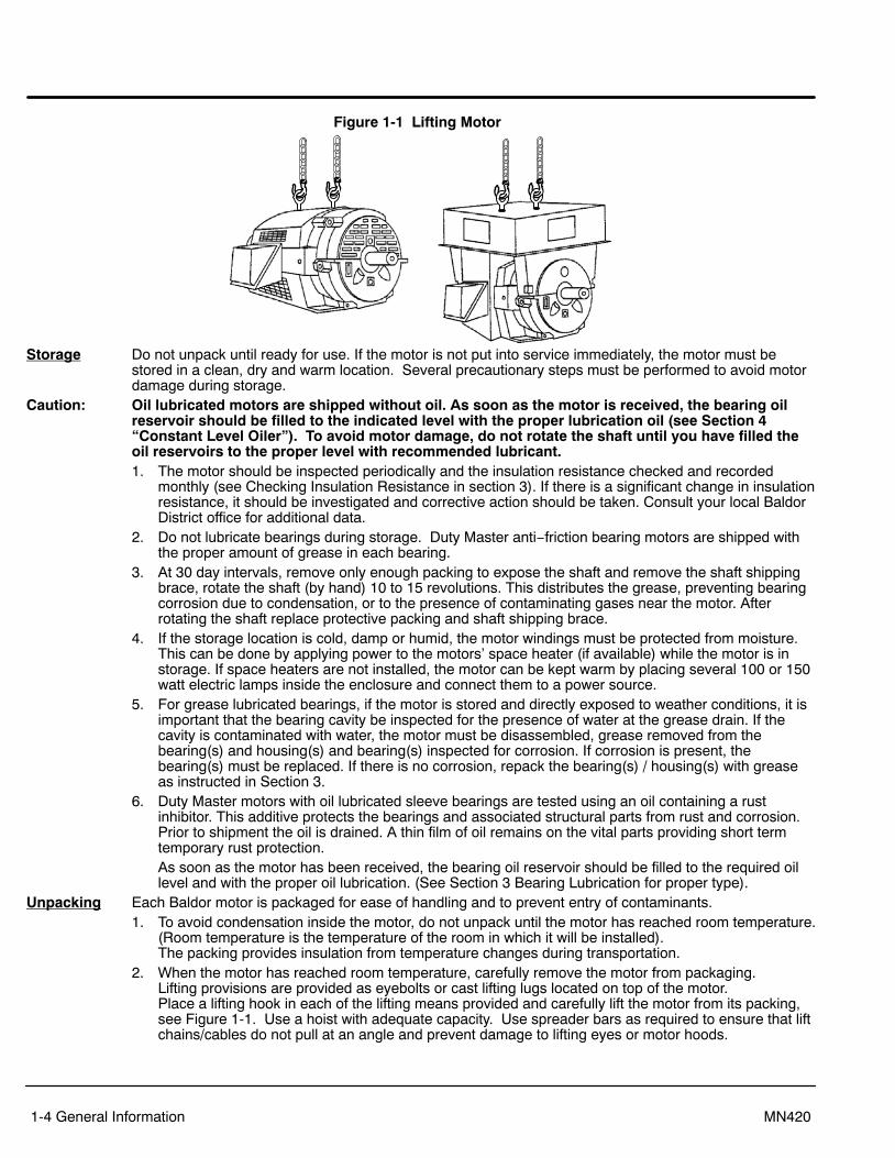
purchase order.Handling The motor should be lifted using the lifting lugs or eye bolts provided.
1. Eyebolts or lifting lugs are intended for lifting only the motor with the standard factory installedaccessories such as tachometer, etc., the lifting means on the motor must not be used to lift the motorplus additional equipment such as gears, pumps, compressors, or other driven equipment. The liftingmeans on the motor cannot be used to lift assemblies of motor and other equipment mounted on acommon base.
2. In all cases, care should be taken to assure lifting in the direction intended in the design of the liftingmeans. Lift using all lugs provided using a hoist with adequate capacity.Be sure lift or hoist equipment has appropriate tires for the terrain to avoid becoming stuck or tippingover. If the shipping pallet is intact, use a fork lift to move the motor. If the shipping pallet is not used,lift using all lugs provided. Likewise, precautions should be taken to prevent hazardous overloads dueto deceleration, acceleration or shock forces. Angle of lift with rope or chain never to be less than 45from horizontal.
1-4 General Information MN420
Figure 1-1 Lifting Motor
Storage Do not unpack until ready for use. If the motor is not put into service immediately, the motor must bestored in a clean, dry and warm location. Several precautionary steps must be performed to avoid motordamage during storage.
Caution: Oil lubricated motors are shipped without oil. As soon as the motor is received, the bearing oilreservoir should be filled to the indicated level with the proper lubrication oil (see Section 4“Constant Level Oiler”). To avoid motor damage, do not rotate the shaft until you have filled theoil reservoirs to the proper level with recommended lubricant.1. The motor should be inspected periodically and the insulation resistance checked and recorded
monthly (see Checking Insulation Resistance in section 3). If there is a significant change in insulationresistance, it should be investigated and corrective action should be taken. Consult your local BaldorDistrict office for additional data.
2. Do not lubricate bearings during storage. Duty Master anti−friction bearing motors are shipped withthe proper amount of grease in each bearing.
3. At 30 day intervals, remove only enough packing to expose the shaft and remove the shaft shippingbrace, rotate the shaft (by hand) 10 to 15 revolutions. This distributes the grease, preventing bearingcorrosion due to condensation, or to the presence of contaminating gases near the motor. Afterrotating the shaft replace protective packing and shaft shipping brace.
4. If the storage location is cold, damp or humid, the motor windings must be protected from moisture.This can be done by applying power to the motors’ space heater (if available) while the motor is instorage. If space heaters are not installed, the motor can be kept warm by placing several 100 or 150watt electric lamps inside the enclosure and connect them to a power source.
5. For grease lubricated bearings, if the motor is stored and directly exposed to weather conditions, it isimportant that the bearing cavity be inspected for the presence of water at the grease drain. If thecavity is contaminated with water, the motor must be disassembled, grease removed from thebearing(s) and housing(s) and bearing(s) inspected for corrosion. If corrosion is present, thebearing(s) must be replaced. If there is no corrosion, repack the bearing(s) / housing(s) with greaseas instructed in Section 3.
6. Duty Master motors with oil lubricated sleeve bearings are tested using an oil containing a rustinhibitor. This additive protects the bearings and associated structural parts from rust and corrosion.Prior to shipment the oil is drained. A thin film of oil remains on the vital parts providing short termtemporary rust protection.As soon as the motor has been received, the bearing oil reservoir should be filled to the required oillevel and with the proper oil lubrication. (See Section 3 Bearing Lubrication for proper type).
Unpacking Each Baldor motor is packaged for ease of handling and to prevent entry of contaminants.1. To avoid condensation inside the motor, do not unpack until the motor has reached room temperature.
(Room temperature is the temperature of the room in which it will be installed). The packing provides insulation from temperature changes during transportation.
2. When the motor has reached room temperature, carefully remove the motor from packaging. Lifting provisions are provided as eyebolts or cast lifting lugs located on top of the motor. Place a lifting hook in each of the lifting means provided and carefully lift the motor from its packing,see Figure 1-1. Use a hoist with adequate capacity. Use spreader bars as required to ensure that liftchains/cables do not pull at an angle and prevent damage to lifting eyes or motor hoods.

Section 2Installation & Operation
Installation & Operation 2-1MN420
Overview Installation should conform to the National Electrical Code as well as local codes and practices. Whenother devices are coupled to the motor shaft, be sure to install protective devices to prevent futureaccidents. Some protective devices include, coupling, belt guard, chain guard, shaft covers etc. Theseprotect against accidental contact with moving parts. Machinery that is accessible to personnel shouldprovide further protection in the form of guard rails, screening, warning signs etc.1. If the motor has been in storage for an extended period or had been subjected to adverse moisture
conditions, check the insulation resistance of the stator winding (see Checking Insulation Resistancein section 3).
2. Examine the motor nameplate data to make sure it agrees with the power circuit to which it will beconnected. The motor is guaranteed to operate successfully at line frequency not more than 5%, andline voltage not more than 10%, above or below the nameplate ratings, or a combined variation ofvoltage and frequency of not more than 10% above or below nameplate ratings. Efficiency, powerfactor and current may vary from nameplate data.
3. Check to make sure that direction of motor rotation is corrected for the intended application.Location It is important that motors be installed in locations that are compatible with motor enclosure and ambient
conditions. Improper selection of the motor enclosure and ambient conditions can lead to reducedoperating life of the motor. The motor must be located in an environment that satisfies local codes. Forlocations outside the USA., compliance with IEC requirements and other regulatory agencies arerequired. The following additional considerations should also govern its location:For open and protected motors the installation should be in a location that provides adequate space forair circulation of the external cooling fan. Exposure to high ambient temperatures, humidity andatmospheric contamination should be avoided. Acids, alkalis and gases also have detrimental effects onelectrical machinery. The location of installation should be accessible for routine maintenance andinspection.If the room is not large enough to have natural ventilation, some external source of forced and filtered airwill be necessary. The room should be such that the heat developed during operation can escape and willnot be recirculated over the equipment.Permanent handling equipment to facilitate major service and repair without complete disassembly of theindividual units should be considered.If the motor must be moved or additional handling or shipment of motor be required, be certain to blockthe shaft as it was blocked for shipment by the factory. Blocking the shaft, limits the rotor movement bothaxially and radially which prevents damage to the bearings.Hazardous Locations are those where there is a risk of ignition or explosion due to the presence ofcombustible gases, vapors, dust, fibers, or flyings. Facilities requiring special equipment for hazardouslocations are typically classified in accordance with local requirements. In the US market, guidance isprovided by the National Electric Code.EMC Compliance Statement for European Union The motors described in this instruction manual are designed to comply 2004/108/EC . These motors arecommercial in design and not intended for residential use.
Foundation The dimensions for mounting are shown on the outline drawing supplied with the motor software andshould be referred to prior to planning of the foundation.Large motors require a concrete foundation. The foundation should consist preferably of solid concretewalls or piers and should be carried down far enough to rest on a solid sub base. This base should besufficient stiffness to prevent vibration and to insure long, trouble free operation. If necessary, a consultingengineer, who is familiar with foundation design, should design and supervise its construction.If the foundation is to be steel girders instead of concrete, the girders should be well braced andsupported by adequate columns to prevent vibration due to resonance. The natural frequencies of themotor and supporting structure must be at least 20% away from the speed of rotation and twice the speedof rotation and multiples of the power line frequency.The size of the foundation is determined by the weight, size and speed of the equipment and by the typeand condition of the underlying soil. The width and length of the foundation are usually made to extend atleast 6 inches (150mm) beyond the equipment on all sides of the base. Increased width and weight arenecessary for operation at higher speeds and for foundations that project above the floor level to givestability against rocking and resonant vibration.Large motors are not rigid or self supporting, and should be uniformly supported. Therefore, when set onthe foundation or base, adequate support should be provided by leveling plates and shims between theframe and the foundation, at points of loading; Le., under the frame feet, and intersection points of thebeams as well as under long, unsupported sections of the base. The number of shims should be kept to aminimum. A few thick ones are preferred over many thin ones.

2-2 Installation & Operation MN420
A 1 inch (25mm) space should be allowed between the base and foundation for grouting. The concretesurface should be roughed to provide a good bonding surface. The lateral clearance for positioning thebase can be made by providing a space around the hold down bolts, that are secured head down to ananchoring washer, Figure 2-1. A sleeve may be used to form the hole when poring the foundation aroundthe bolt for the length between the anchoring washer and the top surface of the concrete foundation. The size and depth of the hole will depend upon the size of the motor and accuracy of the hole location. A template can be used to locate the hold down bolts. The bolts can be locked in place later, by filling theclearance hole with grout.
Figure 2-1 Suggested Foundation Bolt Installation
Foundation PipeBolt
Washer
Pre Installation Checks The assurance of successful start−up depends upon the use of good handling, inspection,and installation practices.Before shipment, every motor is given a running test to check operation. Although complete factory testshave been made, motors should be checked for any change resulting from improper handling duringshipment, storage, installation or by an unsatisfactory foundation. Failure to check or do the necessarywork as mentioned above, could cause misalignment resulting in vibration and premature bearing failure.Before the motor is checked for alignment, remove all shipping blocks and supports installed at thefactory. The shaft should turn over freely. The degree of accuracy required in the alignment depends onthe rated speed of the machine. The greater the speed, the greater the care and accuracy necessary inthe alignment.The motor must be level to maintain the proper oil level. Check the driven equipment to make sure thatthe motor will be coupled to a level shaft. If necessary, level it up before coupling.
Doweling & Bolting After proper alignment is verified, dowel pins should be inserted through the motor feet into thefoundation. This will maintain the correct motor position should motor removal be required. (Baldor motorsare designed for doweling.)1. Drill dowel holes in diagonally opposite motor feet in the locations provided.2. Drill corresponding holes in the foundation.3. Ream all holes.4. Install proper fitting dowels.5. Mounting bolts must be carefully tightened to prevent changes in alignment. Use a flat washer and
lock washer under each nut or bolt head to hold the motor feet secure. Flanged nuts or bolts may beused as an alternative to washers.
Soft foot is a condition in which one or more of the motor feet do not rest squarely on the base. This condition causes distortion of the motor frame once the mounting bolts are tightened and canlead to elevated vibration levels. Prior to alignment, the following procedure should be followed tominimize the effects of soft foot.a. With the motor mounted on the base use a dial indicator to measure the soft foot deflection at
each mounting location.b. With all feet firmly torqued to 120 ft−lbs loosen and tighten each foot measuring the total foot
deflection. The total foot deflection should not exceed 2.00 mils.c. If the foot deflection exceeds 2.00 mils shim foot as necessary to reduce deflection”.
6. Tighten all motor mounting bolts to the identical recommended initial torque value.7. Place a dial indicator to read vertical displacement on the top of a motor foot.8. Loosen the mounting bolt in that foot and record the amount of deflection shown by the dial indicator.9. Foot deflection should be limited to 0.001”−0.002”. If deflection exceeds this level, proceed to step
10. If it does not, proceed to step 11.10. Place an amount of shims that corresponds to the measured deflection under the foot.11. Retighten the bolt and repeat the procedure on the remaining motor feet.

Installation & Operation 2-3MN420
Coupling1. In preparation for making the coupling alignment, wash off the rust protective slushing compound on
the motor shaft and factory installed couplings with solvent. On sleeve bearing motors. remove therust preventative from the shaft to expose the magnetic center and rotor float scribe lines. Fill oil sumps with proper oil to the proper level.
2. The couplings should be heated for proper mounting. Do not press or drive it onto the shaft. The shaft extension key length should be sized per Figure 2-2.
Figure 2-2 A
LB
L= Key LengthA= Coupling Hub LengthB= Keyway Length
L �A � B
2
3. Motors supplied with sleeve bearings.The drive end shaft Extension is scribed with three lines indicating the magnetic center line and rotorend float limits. A single scribe line, magnetic center only is used in cases where the float extremescribe lines would interfere with a shaft shoulder or extension keyway.The magnetic center scribe line is filled with light colored paint and covered with masking tape prior tocoating with rust protection. The distance from the magnetic center scribe line to the referencesurface is indicated on a name plate attached to the motor frame. The magnetic center is within +0.06in. (+1.5 mm) of the rotor float mechanical center. Rotor end float is 0.50 inch (12.7 mm) minimum.Sleeve bearing motors are not designed to withstand external axial thrust. A limited axial floatcoupling should be used. Total end float of the coupling should not exceed 0.19 inch (4.8 mm) (.09inch. +2.3 mm).The motor axial placement should be established by locating the shaft on its magnetic center andspaced from the driven equipment as recommended by the coupling manufacturer.
4. After the motor is properly positioned for axial end play and with the hold down bolts snug but nottightened prepare for the coupling alignment. Mount the coupling hubs, but do not engage thecoupling.
Coupling Alignment There are a number of procedures to properly align the motor to the driven equipment. The end resultdepends upon the accuracy of the parts in roundness, flatness, runout of the reference surfaces, rigidityof the mounting and the skill of the setup man. The motor base surfaces must be flat and parallel to theshafts. Make allowance for inserting shims under the motor to make the elevation adjustment.
The shims size should be the full length of the motor foot pad, they should be flat, and free from burrs.Insert the shims carefully to maintain the foot plane and to avoid bending or twisting the motor frame. Fora poor mounting surface, it may be necessary to machine a shim to compensate for the slope or surfaceirregularity. To minimize soft stacking, use the thickest shim stock combination with the fewest shims.A preliminary line up can be made with feeler gauge by measuring at top, bottom and sides betweenfaces of the hubs. Angular alignment is satisfactory when there is no more than .002 in. (0.05 mm)difference between all sides of the hubs. Parallel alignment check can be made with a straight edge, ordial indicator, to determine if both hubs are parallel within 0.002 in. (0.05 mm). During shimming useshims that are as thick as possible to avoid a sponginess of an excessive number of layers.
Coupling Alignment Procedure
For more accurate alignment, refer to the manual for the driven equipment. When alignment is complete,tighten the motor and driven equipment hold down bolts and recheck alignment. The feet must betightened uniformly. Ensure the feet are on the same plane by measuring the feet spring back when a boltis loosened. It should not exceed 0.002 inch (0.050 mm) at any foot as the others remain tight. Repeatwith two adjacent bolts loose. The shaft spring back should not exceed 0.001 inch (0.025 mm).In some cases it may be necessary to make a hot alignment check to compensate for thermal expansion.A compensating offset alignment should be made cold. The unit may run rough until the equipmenttemperatures stabilize.If for any reason alignment does not fall within limits, contact your local Baldor District Office.
2-4 Installation & Operation MN420
GroutingGrout should be used, but should not be applied until all alignment and leveling have been completed,and the set is running satisfactorily – from the bearing noise, temperature and vibration standpoint – afterthe 4 hour run in test. A good quality commercial non shrinking type of grouting compound should beused. A cement/sand ratio of 1:1 is recommended. Grout should be used with a minimum quantity ofwater to give a stiff mix. The roughened concrete surface should be washed to remove the dust and looseparticles. Grouting should be applied to a wet surface but to assure a good bond, there must be nopuddles of water or contamination from oil or grease. Prepare only the amount that can be handled withinset time and without adding water to the original mix. The grouting should be done quickly andcontinuously. Tamp in place and vent the pockets to assure a solid casting, it is suggested that the motorremain idle while the grout is hardening. At least 48 hours curing timed is desirable for that grout todevelop adequate strength before operating this set, or any nearby large equipment which could create avibration.
Lubrication The lubrication system should be checked in preparation for rotating the shaft during the alignmentoperation.
Anti Friction Bearings (Grease Lubricated)
Bearing chambers are packed with grease during assembly, and do not normally need additional greaseat time of installation, unless the unit has been in storage and installation for 6 months or longer. Lubricant must be added per Section 3, Maintenance.
Sleeve Bearing (Oil Lubricated)
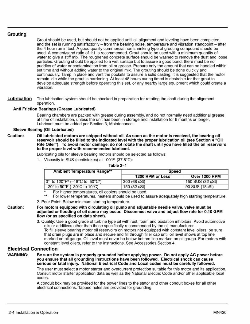
Caution: Oil lubricated motors are shipped without oil. As soon as the motor is received, the bearing oilreservoir should be filled to the indicated level with the proper lubrication oil (see Section 4 “OilRite Oiler”). To avoid motor damage, do not rotate the shaft until you have filled the oil reservoirsto the proper level with recommended lubricant.Lubricating oils for sleeve bearing motors should be selected as follows:1. Viscosity in SUS (centistokes) at 100F. (37.8C):
Table 2−1Ambient Temperature Range** Speed
1200 RPM or Less Over 1200 RPM0 to 120F* (–18C to 50C*) 300 (68 cSt) 150 SUS (32 cSt)–20 to 50F (–30C to 10C) 150 (32 cSt) 90 SUS (18cSt)
* For higher temperatures, oil coolers should be used.** For lower temperatures, heaters should be used to assure adequately high starting temperature.
2. Pour Point: Below minimum starting temperature.Caution: For motors equipped with circulating oil pump and adjustable needle valve, valve must be
adjusted or flooding of oil sump may occur. Disconnect valve and adjust flow rate for 0.10 GPMflow (or as specified on data sheet).3. Quality: Use a good grade of turbine type oil with rust, foam and oxidation inhibitors. Avoid automotive
oils or additives other than those specifically recommended by the oil manufacturer. To fill sleeve bearing motor oil reservoirs on motors not equipped with constant level oilers, be surethat drain plugs are in place and secure and fill through filler cap until oil level shows at top linemarked on oil gauge. Oil level must never be below bottom line marked on oil gauge. For motors withconstant level oilers, refer to the instructions. See Accessories Section 4.
Electrical ConnectionWARNING: Be sure the system is properly grounded before applying power. Do not apply AC power before
you ensure that all grounding instructions have been followed. Electrical shock can causeserious or fatal injury. National Electrical Code and Local codes must be carefully followed.The user must select a motor starter and overcurrent protection suitable for this motor and its application.Consult motor starter application data as well as the National Electric Code and/or other applicable localcodes.A conduit box may be provided for the power lines to the stator and other conduit boxes for all otherelectrical connections. Tapped holes are provided for grounding.

Installation & Operation 2-5MN420
Grounding Failure to properly ground the motor may cause electrical shock hazard to personnel. Do not attachground lead to motor foot bolt. In the USA consult the National Electrical Code, Article 430 for informationon grounding of motors and generators, and Article 250 for general information on grounding. In makingthe ground connection, the installer should make certain that there is a solid and permanent metallicconnection between the ground point, the motor or generator terminal housing, and the motor orgenerator frame. In non−USA locations consult the appropriate national or local code applicable.
All large motors should be grounded with the grounding conductor equipped with a brazed copperterminal, or with a suitable solderless terminal fastened to the motor. Soldered terminals should not beused. A washer should be used between bolt head and terminal lug. The other end should be fastenedwith suitable clamps or terminals to rigid metallic conduit or to the nearest available ground. Groundconductor size should be in accordance with the following National Electrical Code Table 250−122.Installation restrictions are listed in Section 250−120.
Table 2−2 Size of Equipment Ground Conductor
Rating or Setting of Automatic Overcurrent Device in CircuitAhead of Equipment, Conduit, etc., Not Exceeding (Amperes)
SizeCopper Wire No. Aluminum or Copper Clad Aluminum Wire No.*
15 14 1220 12 1030 10 840 10 860 10 8100 8 6200 6 4300 4 2400 3 1500 2 1/0600 1 2/0800 0 3/0
1000 2/0 4/01200 3/0 250MCM1600 4/0 350MCM2000 250MCM 400MCM2500 350MCM 600MCM3000 400MCM 600MCM4000 500MCM 800MCM5000 700MCM 1200MCM6000 800MCM 1200MCM
For motors installed in compliance with IEC requirements, the following minimum cross sectional area ofthe protective conductors should be used:
Crosssectional area of phase conductors, S
Minimum crosssectional area of the corresponding protective conductor, Sp
mm2 mm2
S< 16 S
16 < S � 35 16S>35 0,5 S
Equipotential bonding connection shall made using a conductor with a cross-sectional area of at least 4 mm2.
2-6 Installation & Operation MN420
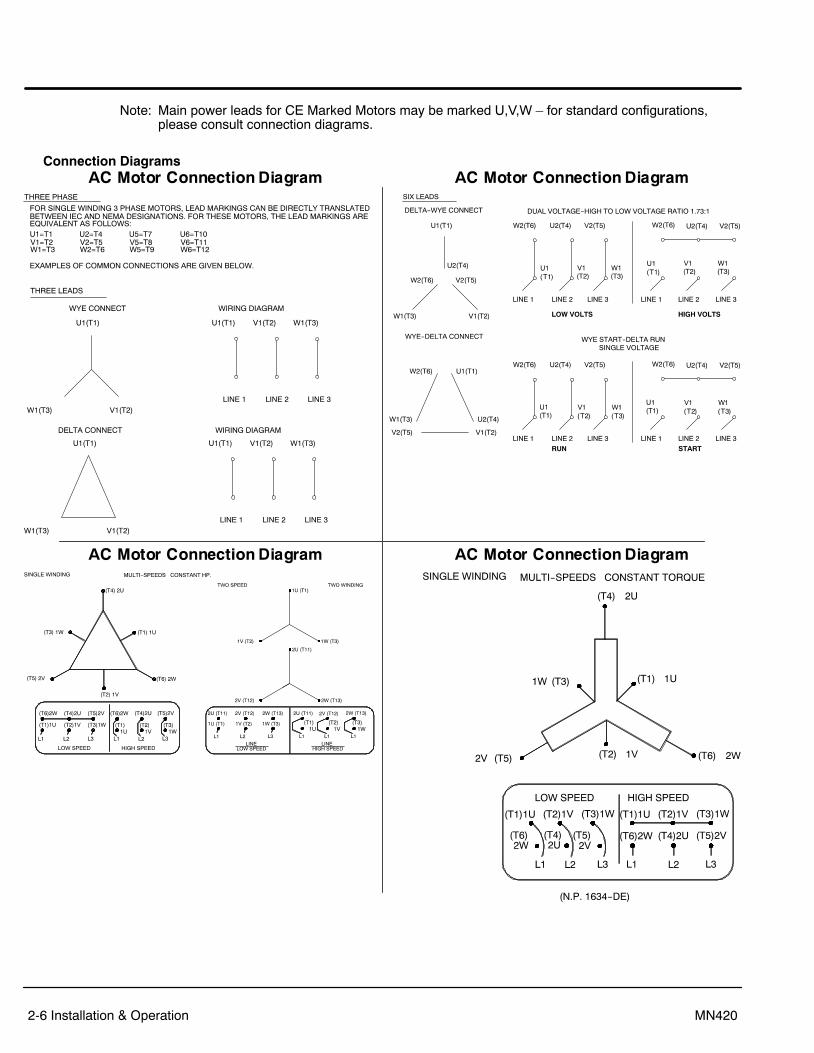
Note: Main power leads for CE Marked Motors may be marked U,V,W – for standard configurations, please consult connection diagrams.
Connection Diagrams

Installation & Operation 2-7MN420
Connection Diagrams Continued
Caution: The space heaters are designed to operate at or below the maximum surface temperature statedon the nameplate. If the marked ambient and/or voltage are exceeded this maximum surfacetemperature can be exceeded and can damage the motor windings. If applied in a division 2 orzone 2 environment this excessive temperature may cause ignition of hazardous materials.

2-8 Installation & Operation MN420
WARNING: This equipment is at line voltage when AC power is connected. Disconnect and lockout allungrounded conductors of the ac power line before proceeding. Failure to observe theseprecautions could result in severe bodily injury or loss of life.
Pre−Operation Check Be sure that all power to motor and accessories is off. Be sure the motor shaft is disconnectedfrom the load and will not cause mechanical rotation of the motor shaft.1. Verify that Hold Down bolts are tightened to the proper torque.2. If the motor has been idle for a long period of time after installation, check insulation resistance.3. Check the incoming power to be sure that line voltage, frequency and phase are correct for the motor
(refer to the motor nameplate).4. Inspect all electrical connections for proper termination, clearance, mechanical strength and electrical
continuity.5. Be sure all shipping materials and braces (if used) are removed from motor shaft.6. Ensure alignment is correct and motor is properly lubricated.
a. On machines supplied with oil lubricated bearings inspect lubrication system to insure that oilreservoirs have been filled to the proper level with correct oil. Do not overfill oil reservoirs.
b. Motors operating with a forced lubrication system must have the forced lubrication systemoperating before starting the motor.
7. Manually rotate the motor shaft to ensure that it rotates freely.Caution: When driven equipment may be damaged by incorrect rotation direction, uncouple the motor from
the load and check motor rotation direction during initial start and be sure rotation is correct.8. When the driven machine is likely to be damaged by the wrong direction of rotation, it is best to
uncouple the motor from its load during the check for rotation and/or during the initial start.Some motors are designed for a single direction of rotation as indicated by nameplates. Runningthose units in the wrong direction will reduce airflow causing overheating. Check to see that both themotor and driven equipment are operating in the correct direction of rotation. If it is necessary tochange rotation, disconnect and lockout all input power and interchange any two input power phases.
9. Replace all panels and covers.10. Check to see that coupling guards and other protective enclosures are not blocking the ventilating air
into the motor and exhaust openings.First Time Uncoupled Start−Up
Read each of the steps in the following procedure over thoroughly, so that each is fully understood, beforeattempting to start the motor.1. Make the initial start by following the regular sequence of starting operations in the control
instructions.2. After starting, check that the motor is running smoothly. If the motor has excessive vibration, shut
down immediately and investigate. Check for coupling and key unbalance, rusty bearing, lack oflubrication, foot planarity, structural resonance.
3. Check bearing temperatures frequently. Bearing temperature should not exceed 185F (85C). Likewise the rate of temperature rise should not be excessive. At initial start, the bearing temperaturerate−of−rise is more indicative of trouble than overall temperature for a minimum of two hours, if atany time the rate of rise curve appears too steep, stop the motor immediately and re−check itsalignment.
4. Ensure that the protective controls are functioning properly before any prolonged operation.5. Run the motor for at least two hours.

Installation & Operation 2-9MN420
Coupled Start−up This procedure assumes a coupled start up. Also, that the first time start up procedure wassuccessful. Read and fully understand each of the steps in the following procedure before attempting tostart the motor.1. Disconnect and lockout the power source. Ensure no power is applied to the motor.2. After a successful uncoupled start, assemble the coupling and lubricate with the manufacturer’s
recommended lubricant. Check to see that the coupling is not binding.3. Verify the motor shaft is on its magnetic center.4. Verify coupling axial movement is within the bearing float limit.5. Check to see that coupling guards and other protective enclosures are not blocking the ventilating air
over the motor and exhaust openings.6. Try no load coupled start−up, repeating steps 1 to 5 of the “First Time Uncoupled Start−up”
procedure.7. Verify the driven equipment is not transmitting vibration back to the motor through the coupling or base.8. Inspect the motor carefully. Make the initial start by following the regular sequence of starting
operations in the control instructions.9. After starting, check that the motor is running smoothly. If the motor shows excessive vibration, shut
down immediately and investigate. Check for coupling and key unbalance, lack of lubrication, footplanarity and structural resonance.
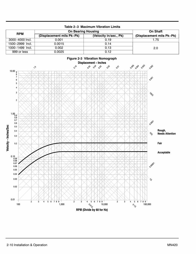
10. Check vibration at the bearing housing. Motor vibration must not exceed the limits given in Table 2−3.Vibration severity and conversion of the above limits to velocity or acceleration can be determined byusing the vibration nomograph in Figure 2-3. Nomograph shows accepted industry vibration levels.
11. Verify all panels and covers are securely in place.12. Verify that coupling guards are properly installed and protective enclosures are not blocking the
ventilating air into the motor and exhaust openings.13. In addition, observe the following before attempted start−up of Belted, C−Face/D Flange and Sleeve
bearing motors:a. For belted duty, ensure motor is intended for belted service and that the belted application data
has been verified. Also be aware that some belted duty motors are built with bearings that arenot suited for non−belted applications.
b. Due to their size, above NEMA C−Face and D−Flange motors are supplied with mounting feetand are not designed to be supported by the C−Face or D−Flange alone.
c. Sleeve bearing motors are intended for horizontal mounting only.Contact your local Baldor District Office for any questions concerning this installation before power isapplied to the motor.
Jogging and Repeated StartsCaution: Repeated starts and/or jogs can greatly reduce the life of an induction motor.
Repeated starts and/or jogs can greatly reduce the life of an induction motor. If it is necessary torepeatedly start or jog a motor, check the application with your local Baldor District office.At ambient temperature, the motor is normally capable of making two starts in succession and coasting torest between starts.The motor is also capable of making one start at its rated load operation temperature. For cooling timerequired before additional starts can be made consult your local Baldor District office or the motor startingnameplate if one is provided.If more starts than defined above are attempted in shorter period of time, severe damage to the motorelectrical windings and rotor may result.The starting conditions listed above apply only if the inertia of the connected load, the load torque duringacceleration, the applied voltage, and the starting method are those for which the motor was designed.For starting situations not covered here, consult your local Baldor District office before proceeding. Refer also to the motor nameplate which may list starting conditions.
2-10 Installation & Operation MN420
Table 2−3 Maximum Vibration Limits
RPMOn Bearing Housing On Shaft
(Displacement mils Pk−Pk) (Velocity in/sec., Pk) (Displacement mils Pk−Pk)3000−4000 Incl. 0.001 0.19 1.751500−2999 Incl. 0.0015 0.14
2.01000−1499 Incl. 0.002 0.13999 or less 0.0025 0.12
Figure 2-3 Vibration Nomograph
100 1,0002 3 4 5 6 7 8 9 2 3 4 5 6 7 8 9 2 3 4 5 6 7 8 9
10,000 100,000
Velo
city
- In
ches
/Sec
0.01
0.02
0.03
0.04
0.05
0.060.070.080.09
0.10
0.2
0.3
0.4
0.5
0.60.70.80.9
1.00
2
3
4
5
678910.00
Displacement - Inches
RPM (Divide by 60 for Hz)
Rough,Needs Attention
Fair
Acceptable

Installation & Operation 2-11MN420
Hazardous LocationsHazardous locations are those where there is a risk of ignition or explosion due to the presence ofcombustible gases, vapors, dust, fibers or flyings.
Selection Facilities requiring special equipment for hazardous locations are typically classified in accordance withlocal requirements. In the US market, guidance is provided by the National Electric Code. Ininternational hazardous location areas, guidance for gas / vapor / mist classification is given inIEC60079−14, or for dust in IEC61241−14. This classification process lets the installer know whatequipment is suitable for installation in that environment, and identifies what the maximum safetemperature or temperature class is required. It is the customer or users responsibility to determine thearea classification and select proper equipment.Areas are classified with respect to risk and exposure to the hazard. In the US market, areas aretypically classified as follows Class, Division, Group and Temperature Class. In some newer installationsin the US and in most international markets, areas are classified in Zones.
Protection ConceptsClass I Division 1 / Zone 1 [Equipment Group I (mining) or II (surface), Equipment Protection Level(EPL) Gb, Mb ]Baldor offers a range of motors suitable for installation in a Division 1 or Zone 1 environment. Thesemotors are known as explosion proof or flameproof.Motors that are explosion proof or flameproof use specially machined flameproof joints between the endbell or bracket and the frame, as well as along the rotating shaft and at connection box covers andentries. The fit of these flameproof joints are designed to contain the combustion or quench the flame ofan explosive gas atmosphere prior to it exiting the motor. These flameproof joints have lengths andwidths selected and tested based on the gas group present in the atmosphere. Baldor�Reliance motorsare typically designed to meet Class I (Division 1) Group C and D (explosion proof) or Ex d IIB(flameproof).An application note regarding equipment applied in accordance with the US National Electric Code (NFPA70−2008) − according to Article 500.8(C) Marking, sub clause (2) in the fine print note, it is noted thatEquipment not marked to indicate a division is suitable for both Division 1 and Division 2 locations. Thesemotors are not gas tight. To the contrary, this protection concept assumes that due to the normal heatingand cooling cycle of motor operation that any gas present will be drawn into the motor. Since flameproofor explosion proof motors are designed to contain the combustion and extinguish any flame transmission,for this protection concept, only external surface temperatures are of concern. Thermal limiting devicessuch as thermostats, thermistors or RTDs may be provided on these motors to limit the external surfacetemperature during overload conditions.If thermostats are provided as a condition of certification, it is the installer’s responsibility to make surethat these devices are properly connected to a suitable switching device. The ATEX directive requiresthat motor shutdown on thermal trip be accomplished without an intermediate software command. Whereintermediate circuitry is involved the circuit shall fall within the scope of a safety, controlling and regulatingdevice as defined in article 1(2) of European Directive 94/9/EC, and shall be covered by an appropriateEC Type Examination Certificate.
2-12 Installation & Operation MN420
Flameproof motors, internationally referred to as Ex d use a protection concept similar to that used inClass I Division 1 motors, with minor differences in the flameproof joints and cable entry designs.Flameproof and explosion proof motors are both type tested. Representative motors are connected to areference gas and ignited in laboratory conditions to verify that the flame is not transmitted outside themotor enclosure and to determine the maximum internal pressure encountered.Explosion proof and Flame proof motors shipped without a conduit box require use of a certified box ofsuitable dimensions and that is appropriate for the classification. Openings in connection boxes must beclosed with suitably certified and dimensioned device.Class I Division 2 / Zone 2 Ex nA, [Equipment Protection Level (EPL) Gc ]This protection concept relies on having no sources of ignition present such as arcing parts or hotsurfaces. For this protection concept, internal temperatures as well as external temperatures areconsidered. In many cases, the internal temperatures are higher than the external temperatures andtherefore become the limiting factor in determination of temperature code designation. In theseapplications, it is very important to use a motor that has been evaluated thermally for use with an inverteror converter, if variable speed operation is desired. Thermostats used for Class I Division 2 and Ex nAmotors are used to protect the motor only. For motors using flying lead construction, it is important to useconnection lugs and insulate with heat shrink tubing or a double wrap of insulation grade electrical tape toavoid the risk of spark or ignition.Class II Division 1 / Zone 21 [Equipment Group III, Equipment Protection Level (EPL) Db ]This area classification is one where the risk of ignitable concentrations of dust is present at all or some ofthe time. The protection concepts used for Class II Division 1 is similar to flamepath, except withadditional dust exclusion paths designed for the rotating shaft. In the international designations, thisconcept is referred to as dust ignition proof or Ex tD. External surface temperature remains the limitingfactor. Thermal limiting devices such as thermostats, thermistors or RTDs may be provided on thesemotors to limit the external surface temperature during overload conditions. If thermostats are providedas a condition of certification, it is the installer’s responsibility to make sure that these devices areproperly connected to a suitable switching device.Note: In the North American area classification system, Class III exists for fibers and flyings.
In the IEC designation, both dusts and flyings are absorbed into Group III.Class II Division 2 / Zone 22 [Equipment Group III, Equipment Protection Level (EPL) Dc ]This area classification is one where the risk of exposure to ignitable concentrations of dust are not likelyto occur under normal operating conditions and relies heavily on the housekeeping practices within theinstallation.Sine Wave Power Operation for Division 1 or 2 and Zone 1 or 2 and Zone 21 or 22 HazardousLocation.These motors are designed to operate at or below the maximum surface temperature (or T−Code) statedon the nameplate. Failure to operate the motor properly can cause this maximum surface temperature tobe exceeded. If applied in a Division 1 or 2 / Zone 1 or 2 and Zone 21 or 22 environment, this excessivetemperature may cause ignition of hazardous materials. Operating the motor at any of the followingconditions can cause the marked surface temperature to be exceeded.1. Motor load exceeding service factor nameplate value2. Ambient temperatures above nameplate value3. Voltages above or below nameplate value4. Unbalanced voltages5. Loss of proper ventilation6. Altitude above 3300 feet / 1000 meters7. Severe duty cycles of repeated starts8. Motor stall9. Motor reversing10. Single phase operation of polyphase equipment11. Variable frequency operationVariable Frequency Power Operation for Division 1 or 2 and Zone 1 or 2 and Zone 21 or 22Hazardous Location (motors with maximum surface temperature listed on the nameplate).Only motors with nameplates marked for use on inverter (variable frequency) power, and labeled forspecific hazardous areas may be used in those hazardous areas on inverter power. The motor isdesigned to operate at or below the maximum surface temperature (or T−Code) stated on the nameplate.Failure to operate the motor properly can cause this maximum surface temperature to be exceeded.

Installation & Operation 2-13MN420
If applied in a Division 1 or 2 / Zone 1 or 2 and Zone 21 or 22 environment, this excessive temperaturemay cause ignition of hazardous materials. Operating the motor at any of the following conditions cancause the marked surface temperature to be exceeded.1. Motor load exceeding service factor nameplate value2. Ambient temperature above nameplate value3. Voltage (at each operating frequency) above or below rated nameplate value4. Unbalanced voltages5. Loss of proper ventilation6. Operation outside of the nameplate speed / frequency range7. Altitudes above 3300 feet / 1000 meters8. Single phase operation of polyphase equipment9. Unstable current wave forms10. Lower than name plate minimum carrier frequencyThermal Limiting Thermal limiting devices are temperature sensing control components installed inside the motor to limitthe internal temperature of the motor frame by interrupting the circuit of the holding coil of the magneticswitch or contactor. They are required for most Division 1 and Zone 1 applications. For Division 2 orZone 2 applications, motors should be selected that preclude running temperatures from exceeding theignition temperatures for the designated hazardous material. In Division 2 or Zone 2 classified locations,thermal limiting devices should only be used for winding protection and not considered for limiting allinternal motor temperatures to specific ignition temperatures.Equipotential Bonding and Shaft Current ReductionLarger motors (ie WP construction) may require proper bonding between motor enclosures and covers toavoid the risk of stray currents during start up. Fastening methods and bonding straps must not be modified.Bearing currents can exist in some motors for both line−fed and inverter−fed applications. Larger line−fedmotors may require at least one insulated bearing to prevent a flow of current through the bearings. Do notdefeat such insulation whether the motor is line−fed or inverter−fed applications. Inverter−fed motors mayrequire additional bearing insulation or even a shaft brush. Do not defeat such features. When the motor andthe coupled load are not on a common conductive baseplate, it may also be necessary to electrically bondtogether the stationary parts of the motor and the coupled equipment.
Repair of Motors used in Hazardous LocationsRepair of hazardous certified motors requires additional information, skill, and care. It is the customer’sresponsibility to select service shops with proper qualifications to repair hazardous location motors.Contact the manufacture for additional repair details. Use only original manufacturer’s parts. Repair of Explosion Proof or Flame Proof Motors Class I Division 1 and Zone 1In the North American market, recertification programs are offered by Underwriters Laboratories andCanadian Standards Association which allow authorized service shops to mark the rebuilt motors ascertified. In the international markets using IEC based requirements, repair should be undertaken onlyafter consulting IEC60079−19 Explosive Atmospheres−Part 19 Equipment repair, overhaul andreclamation. If use of a certified repair facility is desired, consult the IECEX Repair Scheme at
http://www.iecex.com/service_facilities.htmExplosion proof and flameproof motors achieve their safety based on the mechanical construction −flameproof joints and bearing clearance, and the electrical design including any thermal limiting devices. Ifit is necessary to repair a flameproof or explosion proof motor, it is critical that the mechanical flameproofjoints be maintained. Consult Baldor Electric Company for flameproof joint construction details. Use onlyBaldor�Reliance supplied parts. Baldor does not recommend reclamation of parts. Since this protectionmethod also relies on temperature being maintained, make sure that any rewinding uses the originalelectrical designs, including any thermal protection that may be present.Repair of Dust Ignition Proof Motors − Class II Division 1 and 2, Zone 21 and 22. For Dust Ignition Proof, proper sealing is required. Do not modify the motor construction to add anyadditional opening, and ensure that proper sealing is maintained in the connection box and at the shaftseal. Since this protection method also relies on temperature being maintained, make sure that anyrewinding uses the original electrical designs, including any thermal protection that may be presentRepair of Class I Division 2 and Zone 2 motorsFor Division 2 and Zone 2, the internal and external temperatures are of concern. Since this protectionmethod also relies on temperature being maintained, make sure that any rewinding uses the originalelectrical designs, including any thermal protection that may be present. Use only Baldor replacementthermostats, if provided.

2-14 Installation & Operation MN420

Section 3Maintenance & Troubleshooting
Maintenance & Troubleshooting 3-1MN420
WARNING: High Voltage may be present even when the machine is not rotating. Ensure that power has beendisconnected before touching the motor or any of its components. Electrical shock can causeserious or fatal injury.
WARNING: Solvents can be toxic and/or flammable. Follow manufacturer’s safety procedures and directions.Failure to observe this precaution could result in bodily injury.
Caution: Do not use solvents containing trichloroethane to clean interior or exterior of motor. Damage mayoccur to paint and insulation systems.
For Vertical Shaft Motors, refer to Section 5 for Maintenance procedures and intervals.
Horizontal Shaft MotorsThere are two inspection periods which are important to the proper operation and maintenance of yourBaldor motor.These occur every 3 months (or 500 operating hours – which ever comes first) and every six months,respectively, in addition, the following should always be observed.� Provide adequate ventilation.� Keep air and exhaust openings clean and free of obstructions.� Avoid sharp blows and excessive axial thrust loads on the output shaft.� Maintain proper lubricant level (check weekly on oil lubricated units).Duty Master Large AC Motors when properly applied, are very easy to maintain. Since clearances andfits are precisely machined, there are no periodic mechanical adjustments to make. Like any precisionmachine, periodic inspection and simple routine maintenance will prolong your motor’s life and helplocate potentially damaging conditions before they become problems. The minimal time spent performingthese simple procedures cannot begin to compare with the cost of lost productivity and time consumingmajor repairs incurred through neglect of routine inspection and maintenance.
Periodic Inspection Inspections are important to the proper operation and maintenance of a motor.3 months (or 500 operating hours whichever comes first).
1. Listen for any abnormal noises and check cause immediately.2. Check for any vibration and check cause immediately if excessive vibration is found.3. Check voltage and frequency variations. Unbalanced voltage or single phase operation of poly phase
motors will cause excessive heating and ultimately failure. Only a slight unbalance of voltage appliedto a poly phase motor will cause large unbalance currents and result in overheating.
4. Check power supply total harmonic distortion to avoid overheating.5. Periodic checks of phase, voltage, frequency, and power consumption of an operating motor are
recommended. These checks can also provide an excellent indication of the load from the drivenequipment. Comparisons of this data with previous no load and full load power demands will give anindication of the performance of the driven machine.
6. Check to see that air filters, when used, are in place and clean.7. Check all air passages and ensure that they are not blocked or clogged.8. Check for proper lubrication. For sleeve bearing motors check oil level. The oil level must be at the
midpoint of sight gauge when the motor is at rest and in operation.9. When provided, check that constant level oilers have oil in them.
Check that cap on oiler is screwed on tightly. Make sure the oil is clean.10. Check bearing temperature rise.11. Disconnect and lockout the power source. Ensure no power is applied to the motor.12. Check all electrical connectors to be sure that they are tight and corrosion free.13. Check for frayed interconnecting wires, especially at points where it contacts the motor frame.14. Verify that all covers and guards are in place and fasteners are properly torqued.These checks can also provide an excellent indication of the load from the driven equipment.
Semi−Annual Maintenance
1. Inspect and clean rotor ends, windings and fan blades (Open Motors only).2. Check electrical connections for tightness and absence of corrosion.

3-2 Maintenance & Troubleshooting MN420
Bearing LubricationDepending on the application and rating, the horizontal motor is equipped with either anti−friction orsleeve type bearings. When properly cared for (ie., inspection and lubrication) bearings will provide yearsof uninterrupted service. Use one of the following lubrication procedures, depending on the type ofbearings with which your motor is equipped.
Anti−Friction Bearing (Grease Lubricated)This motor has been properly lubricated at the time of manufacture and it is not necessary to lubricate attime of installation. When the motor has been in storage for a period of six months or more, lubricatebefore starting.Lubrication of anti−friction bearings should be done as a part of a planned maintenance schedule. TheRecommended Lubrication Interval should be used as a guide to establish this schedule.Cleanliness is important in lubrication. Any grease used to lubricate anti−friction bearings should be freshand free from contamination. Similarly, care should be taken to properly clean the grease inlet area of themotor to prevent grease contamination.The relubrication periods shown in Table 3-2 are offered as a guide for different speeds, bearing types,operating time and service conditions (Table 3-1).Recommended LubricantRefer to motor nameplate for recommended lubricant. If none is shown, the recommended lubricant isMobil Polyrex EM. The following is a list of alternate lubricants.Operating TEMP. –25C (−15F) to 50C (120F)
Mobil POLYREX EMChevron Oil SRI Shell Oil Co. STAMINA RL2
Use only clean, fresh grease from clean containers.Do not mix greases unless compatibility has been checked and verified. Contact your Baldor District Office if you have compatibility questions.For motors operating in ambient temperatures shown below, use the following lubricant or its equal:Minimum Starting Temperature −76C (–100F)
Shell Oil Co. AEROSHELL #7Procedure1. Select service conditions from Table 3-1.2. Select lubrication frequency (Table 3-2).3. Select recommended volume fill from Table 3-3.
Table 3-1 Service Conditions
StandardConditions
Eight hours per day, normal or light loading, clean ambient air at 40C (100F) maximum
SevereConditions
Twenty four hours per day operation or shock loading, vibration,ambient air containing dirt or dust at 4050C (104−122F)
ExtremeConditions
Heavy shock or vibration, ambient air containing dust, dirt or highhumidity and temperature in excess of 40C (104F)
Table 3-2 Relubrication IntervalsAnti−Friction Bearings
Speed (RPM) Standard Conditions Severe Conditions Extreme Conditions< 3,000 6 months 3 months 3 months> 3,000 6 months 3 months 2 months
Roller Bearing< 3,000 3 months 1.5 months 1.5 months

Maintenance & Troubleshooting 3-3MN420
Table 3-3 Relubrication Volume (cubic inches; Motor Maximum speed − RPM)Frame Size <3,000 RPM >3,000 RPM
5000 & G315 2.5 in3 1.5 in3
5800, G400 3.0 in3 1.5 in3
G500, 7111, 6800, 9500 4.0 in3
Lubrication ProcedureAnti−friction bearings may be lubricated with the motor running or stationary. (Stationary with the motorwarm is recommended.)1. Relubrication with the shaft stationary and a warm motor is recommended.
If lubrication must be done with motor running, stay clear of rotating parts and electrical circuits.2. Locate the grease inlet, clean the area and replace the pipe plug with a grease fitting, if the motor is
not equipped with grease fittings.3. Remove relief plug. If grease is caked around the plug, clean with a wooden stick or suitable tool, if
severe caking appears at the plug, run the motor until the bearing housing is warm, permitting a freeflow of grease through the housing.
4. Locate the motor nameplate. Find the lubricant recommended type and volume. (Table 3-3 is for reference only, Nameplate values should always be used).
5. Add the recommended volume of the recommended lubricant using a hand operated grease gun.6. Run the motor for 1/2 hour with relief plug removed.7. Replace the pipe plugs and wipe off excess grease.
Replacement Bearings
Your maintenance program will not be complete without including spare bearings. Remember that the bearing is a wearable component and therefore must eventually be replaced. To ensure that you are able to maintain original operation we recommend the purchase of spares directlyfrom Baldor. All bearings used in Baldor�Reliance motors are subject to exact specifications. Markings on the bearing do not indicate complete specifications.
Anti−Friction Bearing (Oil Mist Lubricated)The following applies to anti−friction bearing motors built with provisions for oil mist lubrication. At thetime of shipment, the bearings are packed with a minimal amount of corrosion inhibiting grease. Thisprotects the bearings during temporary storage. However, if extended storage (greater than 3 months)or outdoor storage is anticipated, the units should be connected to the oil mist system while in storage.If this is not possible, an amount of grease indicated under standard conditions in the grease chart(Table 3-2) should be added, and the shaft should be rotated several times by hand. (See extendedstorage instructions in appropriate motor instruction manual.)This grease will require removal and all lubrication channels must be cleaned at the time of connection tothe oil mist system.Oil Mist Installation1. Remove all grease from bearings and clean all lubrication channels. This step is necessary on
motors that are labeled “Provisions for oil mist lubrication” or motors built for ”oil mist lubrication”, but filled with grease by user. This step is not required on motors built ”For oil mist lubrication” as’supplied by factory.
2. Remove inlet and outlet pipe plugs from bearing brackets (or extension tubes) on each end of motor.3. Install appropriate reclassifier (Tables 3-4, 3-5 and 3-6) in top opening.4. Connect oil recovery trap to bottom opening or leave open to act as relief.Tables 3-4, 3-5 and 3-6 should be used to select the appropriate reclassifier based on the motor framesize and speed. Foot mounted C & D−Flange Motors as well as Vertical HP Motors use Table 3-4.Vertical LP Motors refer to Table 3-5.
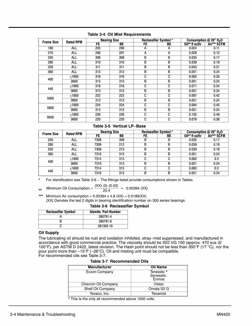
3-4 Maintenance & Troubleshooting MN420
Table 3-4 Oil Mist Requirements
Frame Size Rated RPM Bearing Size Reclassifier Symbol * Consumption @ 20” H2OFE BE FE BE Oil** fl oz/hr Air*** SCFM
180 ALL 205 206 A A 0.024 0.11210 ALL 206 207 A A 0.028 0.13250 ALL 309 309 B B 0.035 0.17280 ALL 310 310 B B 0.039 0.19320 ALL 311 311 B B 0.043 0.21360 ALL 313 313 B B 0.051 0.24
400<1800 316 316 C C 0.063 0.303600 313 313 B B 0.051 0.24
440<1800 318 318 C C 0.071 0.343600 313 313 B B 0.051 0.24
5000<1800 222 222 C C 0.087 0.423600 313 313 B B 0.051 0.24
5800<1800 224 224 C C 0.094 0.453600 313 313 B B 0.051 0.24
9500<1800 226 226 C C 0.102 0.493600 220 220 C C 0.079 0.38
Table 3-5 Vertical LP−Base
Frame Size Rated RPM Bearing Size Reclassifier Symbol * Consumption @ 20” H2OFE BE FE BE Oil** fl oz/hr Air*** SCFM
250 ALL 7308 309 B B 0.035 0.17280 ALL 7309 212 B B 0.039 0.19320 ALL 7309 213 B B 0.039 0.19360 ALL 7310 313 B B 0.051 0.24
400<1800 7314 313 C C 0.063 0.33600 7310 313 B B 0.051 0.24
440<1800 7314 313 C C 0.063 0.33600 7310 313 B B 0.051 0.24
* For identification see Table 3-6 − The fittings listed provide consumptions shown in Tables.
** Minimum Oil Consumption = (XX) (5) (0.02)
25.4� 0.00394 (XX)
*** Minimum Air consumption = 0.00394 x 4.8 (XX) = 0.0189(XX) (XX) Denotes the last 2 digits in bearing identification number on 300 series bearings.
Table 3-6 Reclassifier SymbolReclassifier Symbol Alemite Part Number
A 3807914B 3807916C 38130310
Oil SupplyThe lubricating oil should be rust and oxidation inhibited, stray−mist suppressed, and manufactured inaccordance with good commercial practice. The viscosity should be ISO VG 100 (approx. 470 sus @100F), per ASTM D 2422, latest revision. The Hash point should not be less than 350F (17 C), nor thepour point more than −15F (−26C). Oil and misting unit must be compatible. For recommended oils see Table 3-7.
Table 3-7 Recommended OilsManufacturer Oil Name
Exxon Company Teresstic *Synesstic
EnmistChevron Oil Company Vistac
Shell Oil Company Omala S2 GTexaco, Inc. Texamist
* This Is the only all recommended above 1000 volts.

Maintenance & Troubleshooting 3-5MN420
Sleeve Bearings (Oil Lubricated)Oil should be changed periodically, or immediately if discolored or contaminated. Follow the schedule onthe motor nameplate, or if not known use the Table 3-8 schedule.
Table 3-8 Lubrication ScheduleSpeed − RPM Service Conditions Change Oil (Hours)
All speeds Standard Every 8800 hrs.All speeds Severe & Extreme Every 6 months (4400 hrs.)
Table 3-9
Ambient TemperatureSpeed − RPM
1200 or less Greater than 12000 to120F (−18 to 50C)* 300 SUS (68 cST) 150 SUS (32 cST)
−20 to 50F (−30 to 10C)** 150 SUS (32 cST) 90 SUS (18 cST)* For greater temperatures, oil coolers should be used.** For reduced temperatures, heaters should be used to assure adequate starting temperatures.
Lubricating oil for sleeve bearing motors should be selected as follows:1. Viscosity in SUS (centistokes) at 100F (37.8C).2. Pour point: Below minimum starting temperature.3. Quality: Use a good grade turbine type oil (rust, foam and oxidation inhibited). Avoid automotive oils
or additives other than those specifically recommended by the oil manufacturer.Sleeve Bearing Replacement Open Motor (ODP, WPI, WPII, TEAAC, TEWAC)
Sleeve Bearing Removal1. Remove the end bracket top cover or grill.2. Remove bearing temperature detectors, If the motor is so equipped.3. Remove the bracket top cap from the bracket bottom section. There are typically four cap screws
and two dowel pins holding the cap in place. Two of these cap screws can be used as jack screws toseparate the cap and extract the dowel.
4. Note the location and arrangement of the bearing, oil rings, bearing retainers and shims outboard ofthe bearing.
5. Remove the top half of the bearing. There are typically four socket head cap screws and two dowelsholding the top half in place. After the cap screws have been removed, the bearing top hall can beremoved by hand.
6. Remove the bearing retainers from both sides of the bearing. Note their orientation.7. Using a non−metal sling or jack, raise the shaft to take all the weight off the bearing.8. Remove the bearing bottom half by pulling upward on the bearing oil rings and rolling it around the
shaft 180 degrees. Lift the bearing bottom half from the shaft and bracket.Note: Shims used to limit the axial float are located on the outboard end 01 the bearing. Remove these
shims as the bearing bottom hall is being removed. Note the quantity used at each bearing.9. Lower the shaft onto the bracket seal bore.10. Protect the bearing sump area and bracket top cap from contamination.Sleeve Bearing Installation1. Remove all sealing compound from the mating surfaces of the bracket top and bottom sections.2. Remove all nicks and burrs from the shaft bearing journals and bearing shoulder with a fine stone.3. Drain the oil from the bracket bearing sump by removing the pipe plug on the face of the bracket.
Clean the shaft journal and seal areas with a mild solvent and lint−free cloth. Flush the bearing sumpwith clean 011 or a mild solvent. Clean the threads of the drain plug and coat with a thread sealant.Install the drain plug.
If the original bearing is to be re−installed, apply a coating of bearing oil to the shaft journal. Install the bearing bottom half. shims. bearing retainers and bearing top half. Note that the shims and oilrings are properly located. Proceed to Step 10 for completion of the assembly.

3-6 Maintenance & Troubleshooting MN420
If a new bearing is being installed proceed as follows:1. Using a clean lint free cloth. wipe bearing journal and bearing clean and dry. Shaft and bearing bore
are to be free of oil.2. Raise the shaft as required to reassemble bearing.3. Install the bottom half of the bearing.4. Gently lower the shaft until it is in its final position.5. Assemble top half of bearing.6. Reassemble parts in reverse order of removal. Ensure dowel pins are engaged in top and bottom
halves of housing.7. By hand (or Suitable wrench) slowly rotate the shaft 2 turns in each direction.8. Remove bearing as previously described. Inspect bore of both bearing halves for 15 burnished
(shiny) areas. A correct burnish pattern is: Top half of bearing − no burnished areas.Bottom half of bearing − burnish area symmetric about the 6:00 position. one to two inches wide,covering approximately 70% of the axial length of the bearing bore.
9. If the correct burnish pattern Is not found perform the following:Using the proper bearing scraping tools and/or a non−metallic fiber pad, remove the highly burnishedareas. Clean the bearing and shaft journal with a film−free solvent such as denatured alcohol.
10. Repeat steps 3 − 8 until the correct burnish pattern is obtained.11. Apply a coating of bearing oil to the shaft journal. Install the bearing bottom half, shims, bearing
retainers and bearing top half.Note: The shims and oil rings are properly located and that the bearing retainers properly engage the
bearing.12. Reassemble parts in reverse order of removal. Make sure dowel pins are engaged in top and bottom
halves of housing. Apply a sealing compound (Permatex #3) to the contact surfaces between the (opand bottom bracket segments.
Sleeve Bearing Bracket Removal1. Remove the bearing per the above procedure.2. Support the bracket with a crane or hoist.3. Remove the hex screws that mount the bracket to the motor frame.4. Extract the bracket from the rabbet fit by using four of the mounting hex screws as jack screws in the
threaded holes provided in the bracket ears.5. The Bracket will clear the rabbet fit when moved 0.38 inches (10 mm).6. Bracket assembly is performed in reverse order of these steps. Be sure that all accessories that may
have been removed or moved are reassembled in the proper location.
Sleeve Bearing Replacement Enclosed Motor (TEFC)
G50 Sleeve Bearing Removal
Note: This procedure refers to the RENK type sleeve bearing used on all G50 and Limited 6800 framemotors.
1. Disconnect and lockout the power source. Ensure no power is applied to the motor.2. Remove the fan cover/air scoop and accessories (forced lubrication plumbing) that are assembled to
the end shield and bearing housing.3. Loosen bolts and remove protective cover bolted to flange of the end shield.4. The bearing housing must be disassembled from the end shield before removing the end shield from
the frame.5. Remove drain plug at bottom of bearing housing and drain oil from the reservoir.6. Loosen and remove the bolts at the split line of the bearing housing.7. If the motor has insulated bearings and meets API−541 , a machined seal will be assembled
outboard of the bearing housing. The seal must be dissembled from the bearing housing beforeremoving the top half of the bearing housing. The seal is insulated from the bearing housing with anon−split gasket. The bearing housing top half can not be removed unless the seal and gasket aredisassembled from the bearing housing.

Maintenance & Troubleshooting 3-7MN420
8. Use the lifting eye bolts, lift the bearing housing top half straight up and pull forward away from thebearing area to clear the end shield. Insure that the bearing and seals are cleared before moving thebearing housing top half forward.
9. Lift the upper half of the bearing liner and remove from bearing housing.10. Loosen and remove the bolts at the split line of the oil ring.11. Remove oil ring.12. Disassemble the garter springs that encircle the labyrinth seals (inboard and outboard).13. Lift and remove the upper half of each seal. Rotate the lower half out of the seal carrier.Note: The labyrinth seals must be assembled so that the locking tabs will be in the 9:00 position.
The drain back holes in the seal face must face towards the oil sump and be located in the 6:00position.
14. Disconnect and remove RTD’s from the lower half of the bearing liner.15. Use hoist, jack or a non−metallic sling around the shaft to lift the shaft off the lower half of the
bearing liner. Roll the lower half of the bearing liner out of the bearing housing.16. Loosen and remove the bolts securing the bottom half of the bearing housing to the end shield. Use
eye bolts and hoist to remove the bottom half of housing. Shims for axial location of the shaft arelocated between the lower bearing housing and end cap machined fits. Note their location for reassembly.
17. The inboard machined seal, outboard seal carrier, and bolt on baffle are still attached to the bearinghousing. These parts can be removed by loosening all bolts and disassembling.
18. For reassembly perform the above listed steps in reverse order. Assemble both the bottom and tophalf of the seals. Press up on the bottom half of the outboard seal and baffle so that there is noclearance between the seal and shaft at the bottom. Make sure that the clearance from side to sideis symmetric.
19. All machined split line surfaces of the bearing housing and seals must be coated with a sealingcompound (Curil T or Permatex #3). Also apply seal compound to the flange of the machined sealsand seal carrier.
G50 Sleeve Bearing Replacement
1. The sleeve bearing may be replaced without disturbing the setup and uncoupling from the drivenequipment. Remove the top and bottom bearing liners at stated in “G50 Sleeve Bearing & CartridgeRemoval Instructions”.
2. Make sure that the shaft bearing shoulders and journal are free of nicks and burrs before replacingbearing. Dress shaft with emery cloth or stone as necessary. Clean the shaft and oil sumpthoroughly.
3. Apply a coating of oil to the bearing journal.4. Inspect the replacement bearing for nicks and damage. The bearing may be packed in a waxy rust
inhibiting compound. Remove all wax from bearing surfaces using solvent. Dry bearing beforeassembling in housing. The bearings are spherical self seating. Apply a coat of oil to the outsidediameter of the bearing liner and also to the bearing housing bore. Do not scrape the bearingBabbitt surface for seating.
5. Reassemble the motor. Apply sealant to the split line of bearing housing seals.6. Fill oil reservoir so that oil is at the midway point in the sight gauge.7. Slowly rotate the shaft to insure the bearings and seals are seated properly.
G5000, G315, G5810 and G40 Sleeve Bearing Removal
1. Disconnect and lockout the power source. Ensure no power is applied to the motor.2. Remove the fan cover/air scoop and accessories (forced lubrication plumbing) that are assembled to
the end shield and bearing housing. Loosen bolts and remove protective cover bolted to flange of theend shield.
3. The bearing housing must be disassembled from the end shield before removing the end shield fromthe frame.
4. Remove drain plug at bottom of bearing housing and drain oil from the reservoir.5. Loosen and remove the bolts at the split line of the bearing housing. Remove top half of bearing
housing.6. Pry slots are provided on the outboard bearing face to facilitate removing top of the bearing housing.

3-8 Maintenance & Troubleshooting MN420
7. Using hand pressure, separate the bearing halves. (Bearings halves are doweled together).Note: Some models are equipped with socket head screws in addition to the dowels. These screws must
be removed before attempting to remove bearing top half.
8. Remove top half of bearing and bearing anti−rotation keying devices from bearing housing.9. Remove Bearing RTD’s if supplied.10. Using a rope or sling (Nonmetal) around the shaft, raise it just high enough to be able to spin out the
bottom half of the bearing.Note: Shims used for axial float are located on the outboard end of the bearing in the housing. Remove
and note the quantity used at each end.
11. Remove the bottom half of bearing and gently lower shaft.12. To remove bottom half of bearing cartridge, use eye bolts to support weight of cartridge and then
remove mounting bolts.13. For reassembly perform the above listed steps in reverse order.14. All machined split line surfaces of the bearing housing and seals must be coated with a sealing
compound (Curil T or Permatex #3).G5000, G315, G5810 and G40 Sleeve Bearing Replacement
1. Remove bearing as listed in section “G5000, G315, G581 0 and G40 Sleeve Bearing and CartridgeRemoval”.
2. Check to see that bearing journal and shoulders are free of nicks and burrs; dress with rubber stoneor replace as necessary.
3. Using a clean lint free cloth, wipe bearing journal and bearing clean and dry. Shaft and bearing boremust be free of oil.
4. Raise the shaft as required to reassemble bearing. Install the bottom half of the bearing.5. Gently lower the shaft until it is in its final position.6. Assemble top half of bearing.7. Reassemble parts in reverse order of removal. Make sure dowel pins are engaged in top and bottom
halves of housing.8. By hand (or suitable wrench) slowly rotate the shaft 2 turns in each direction.9. Remove bearing as listed in section “G5000, G315, G581 0 and G40 Sleeve Bearing and Cartridge
Removal”. Inspect bore of both bearing halves for burnished (shiny) areas. A correct burnish pattern is:
Top half of bearing − no burnished areasBottom half of bearing − burnish area symmetric about the 6:00 position, one to
two inches wide, covering approximately 70% of the axial length of the bearing bore.10. If the correct burnish pattern is not found perform the following:a. Using the proper bearing scraping tools and/or a nonmetallic fiber pad, remove the highly burnished
areas.b. Clean the bearing and shaft journal with a film free solvent such as denatured alcohol.11. Repeat steps 3−10 until the correct burnish pattern is obtained.12. Wipe bearing and journal and pour fresh clean oil on bearing journal and over bearing. Be sure to
cover both inside and outside diameters with oil. Install bottom half of bearing. Use caution toprevent damage to bearing and to prevent dirt from contaminating bearing surface.
13. Replace anti−rotation keys. Tabs to prevent axial bearing movement should be install pointing towardthe bearing.
14. Assemble top half of bearing.15. Reassemble parts in reverse order of removal. Make sure dowel pins are engaged in top and bottom
halves of housing. Apply a sealing compound (Curil T or Permatex #3) to faces of lower bearinghousing.

Maintenance & Troubleshooting 3-9MN420
Sleeve/Anti−Friction Bearing Bracket Removal1. For anti−friction bearing motors the inner cap bolts must be removed before removing the end shield.2. For sleeve bearing motors the bearing cartridge must be removed before disassembly of the end
shield. (See Sleeve Bearing & Cartridge Removal).3. Remove all bolts that secure the end shield to the frame.4. Using a hoist, support the bracket.5. To remove the G50 bracket from rabbet fit, jacking holes have been provided next to the four bracket
bolts located at 45. Tighten jack bolts evenly to avoid axial misalignment of the end shield. Toremove the G5000, G315, G5810 and G40 brackets from the rabbet fit, pry bar slots have beenprovided on the lugs.
Anti−Friction Bearing Removal/Replacement1. Remove the end shield (see Sleeve/Anti−Friction Bearing Bracket Removal).2. The bearing can now be removed by using a conventional bearing puller with the puller arms located
behind the bearing race. Protect the shaft center by using a spacer block of bass or some other softmaterial between the shaft and bearing puller.
3. Clean and inspect all parts. Remove all old grease.4. All shaft bearing shoulders and journals should be free of nicks before replacing bearing.
Dress shaft with emery cloth or stone as necessary.5. Heat bearing to 250F (120C) for at least 30 minutes.6. Place bearing onto shaft. Make certain that the bearing is contacting the locating shoulder on shaft.
Do not use impact force on bearing.7. Let the bearing cool. Grease the outboard side cavity of the bearing 100%. Grease inner caps and
bracket bearing housing to 60% full.8. Assemble end shield in reverse order. (See Sleeve/Anti−Friction Bearing Bracket Removal).
Rotor And Stator Removal Consult your local Baldor District office for proper removal procedures.
Winding MaintenanceWARNING: Solvents can be toxic and/or flammable. Follow manufacturer’s safety procedures and directions.
Failure to observe this precaution could result in bodily injury.Caution: Do not use solvents containing trichloroethane to clean interior or exterior of motor.
Damage may occur to paint and insulation systems.1. Disconnect and lockout the power source. Ensure no power is applied to the motor.2. Remove the end cover from the motor. Inspection of the winding ends and outside surfaces provides
a good indication of their general condition. To thoroughly inspect the windings, the rotor may have tobe removed.
There are numerous methods for cleanings windings. The following methods are most commonly used,in order of preference.Note: Before cleaning the windings check for loose blockings, evidence of damage to insulation,
distortion or movement of coils, etc. If any of these conditions exist, contact your local BaldorDistrict office for recommendations.
Dry Wiping This method is satisfactory when the surfaces to be cleaned are accessible and when only dry dirt is tobe removed. Use a clean dry, lint free cloth. The lint will adhere to the insulation and increase dirtcollection. Lint is particularly objectionable on high voltage insulation systems as it tends to concentratecorona discharge.
Brushing and Suction CleaningRemove the dry dust and dirt by brushing with a bristle brush, followed by a vacuum suction cleaning. Do Not Use Wire Brushes.
Blowing
WARNING: Use of an air jet may cause flying debris and generate particulate matter. Wear suitable skin, eyeand respiratory protection. Failure to observe this precaution may result in bodily injury.
Caution: To avoid damage to the windings do not use air pressures greater than 30 psi (200 kPa). Avoiddirecting the air in such a way that the dirt will be blown into inner crevices.Dry dirt and dust can be removed from inaccessible crevices by using a jet of low pressure compressed air.

3-10 Maintenance & Troubleshooting MN420
Solvent Cleaning
WARNING: Be sure to follow all precautions and warnings stated by solvent manufacturer.Caution: Avoid inhaling fumes.Caution: Avoid using flammable solvents and fluids.Caution: Do not use solvents containing trichloroethane to clean interior or exterior of motor. Damage may
occur to paint and insulation systems.Oil, grease, tar and wax can be removed by cloth wetted with solvent, followed by wiping with a dry cloth.Typical solvents are: Atlantic Safety Solvent, Graymills Solvent, De−Greaseall, Zep and Stoddard Solvent.
Cleaning with Water and DetergentWindings can be cleaned by hose washing or by pressure spray from a low pressure steam generator orshop steam line.
Reconditioning (Revarnishing) Windings If after cleaning with solvent or water and detergent, the insulation shows signs of dryness, etc., it maybe necessary to revarnish the windings. Contact your local Baldor District Office for type and propermethod of revarnishing. Oil, grease, tar and wax can be removed by adding a non conductive detergent to the wash water. Afterwashing, it is necessary to dry the windings in an oven. See Checking Insulation Resistance.
Checking Insulation Resistance
If the motor has been in storage for an extensive period or has been subjected to adverse moistureconditions, check the insulation resistance of the stator winding with an insulation resistance meter.The minimum insulation resistance (RM) can be determined from the following formula:
RM = KV + 1WhereRM = Minimum insulation resistance in mega ohms at 40C of the entire machine winding.KV = Rating machine potential, in kilovolts.
For machines in good condition, insulation and resistance readings of 10 to 100 times RM are common.If the insulation resistance is less than that calculated from the formula, the windings should be dried outas follows:1. Bake in an oven (preferably a circulating air oven) at a temperature not not to exceed 90C until
insulation resistance remains constant. Do not exceed this temperature.2. With the rotor locked, apply low voltage and gradually increase current through winding (do not
exceed 50% full load amps) until winding temperature, measured with thermometer, reaches 90C.Do not exceed this temperature.
Auxiliary CoolingMotors supplied with separately powered cooling fans (blowers), pipe in− pipe out flanges, or watercooling connections require proper connection and operation of these features for proper motor cooling.Refer to the motor nameplate{s) or other unit−specific supplied documentation regarding the properconnections, air flow or water flow requirements. Operation of the motor without these auxiliary coolingfeatures engaged will result in motor overheating and premature motor failure.
Renewal Parts A detailed parts list, which gives Baldor’s recommendations for spare parts that should be stocked foryour equipment, can be ordered from the nearest Baldor District Office.Be sure to include complete nameplate data – purchase order number, serial number, model number,rating, etc., – for your equipment when ordering the spare parts list.

Maintenance & Troubleshooting 3-11MN420
Table 3-10 Troubleshooting Guide
PROBLEM POSSIBLE CAUSE CORRECTIVE ACTION
Motor will not start Motor improperly connectedIncorrect Line VoltageOverload relay trippedFuses blown or defectiveOpen circuit in stator or rotorShort circuit in statorGrounded Winding
Check motor connection and control connectionsCheck nameplate for required voltageCorrect and resetReplace fusesCheck for open circuitCheck for short circuitCheck for ground
Motor noisy Winding single phased
Loose mountingNoisy bearingCoupling halves looseVibration
Uneven air gap
If winding is single phased, unit will not start.Stop unit and try to resetCheck and correctCheck and replaceInspect alignment and tighten Check alignment with driver connectedCheck feet planarity Correct balance of motor if necessary Check key unbalance on coupling.Check gap, correct problem.
Excessive BearingTemperature(anti-friction bearing)
Inadequate lubricationCoupling misalignmentInadequate ventilation
Add lubricant per nameplate instructionsRealign unitClean filters, check to see if louvers are blocked
Excessive BearingTemperature (sleevebearing)
(Vertical Shaft)
Excess lubricantInadequate oil supply
Excessive end thrustContaminated oil
Tight clearanceOil rings not functioningBearing material tornRough shaft or corrosionBearing MisalignmentCoupling misalignmentShaft currentOil level too high or lowInsufficient water flow (cooling coil)Excessive water temperature to cooling coil
Clean grease reservoir & add correct lubricant volumeRefer to nameplate requirements and correct Check for proper lubrication, oil level, leaksCheck alignment and coupling floatDrain and refill, change filters in flood lube systemInspect for source of contaminationCheck bearing bore and shaft O.D for proper clearance.Check for damage, check roundness and for burrs - repair or replace if necessaryDress, scrape and refit.Dress and polish shaftRealign bearing or reseat bearingRealign motorInsulate bearing and isolate shaft from groundReduce or add to proper level (sight gauge)Increase water flowDecrease inlet water temperature
ExcessiveTemperature
OverloadRestricted ventilationElectrical
Reduce load to nameplate rating or replace with larger unitCheck openings and duct work for obstructions and correctCheck for grounded or shorted coils and unbalanced voltages between phases
Oil Leak (sleeve bearing units)
OverfilledSeals not secured properlyPipe fittings looseBearing air pressure equalizer vent cloggedWrong sealing compound on bearing cap surface
Drain to proper level or adjust oiler elevationTightenTighten or replace worn threaded partsClear out passageUse Permatex Aviation type No. 3 or other non-hardening gasket sealer
Oil Leak (FloodLubrication System)
To much oil flow in pressure lube systemAir pressure unbalanced
Reduce flow to recommended level on nameplateClean venting pipes
Excessive Vibration Coupling misalignmentCoupling , Coupling key or Rotor UnbalanceFoundation resonance structure improperWorn bearingCoupled equipmentShaft Straightness
Realign to operating conditionRebalanceMake adjustments to foundationReplace bearing if oversizeCheck motor vibration uncoupled, if necessary rebalance equipmentStraighten without residual stress to avoid springback or replace shaft
Water in Sump oil(Vertical Shaft)
Cooling coil leakWater leak at dome cover or non-reverse ratchet
Test cooling coil & repair as requiredReplace dome gasket and or seal with silicone gasket sealer
Oil Leak or excess oilusage (Vertical Shaft)
High oil levelMoisture in oil
Use non-foaming oil. Reduce or add to proper level (sight gauge)Clean & replace oil
Excess oil foaming(Vertical Shaft)
Improper oilHigh oil levelMoisture in oil
Use non-foaming oil.Reduce or add to proper level (sight gauge)Clean & replace oil

3-12 Maintenance & Troubleshooting MN420

Section 4Accessories
Accessories 4-1MN420
The owner is responsible for conformance to national electric code and all other applicable local codesand practices. Refer to Safety Notice in Section 1 of this manual.Note: Motor is equipped with the following accessories only if ordered with the motor.
Winding Resistance Temperature Detector RTDPurposeTo measure or monitor winding temperature during operation.Principle of OperationThe RTD uses a wire wound in a flat ribbon coil. It is wound so that it is a non−inductive device. Its modeof operation is that of a linear change in resistance with temperature.InstallationBaldor typically installs two (2) RTD’s per phase, six (6) in total. Each RTD is located between the topand bottom coils in the slot.Customer InterconnectRTD leads are typically supplied in a separate conduit box. Leads are tagged and connected to aterminal block. One side of the customer’s bridge circuit must be grounded. This can be done either atthe motor terminal box or at the instrumentation end of the circuit. Voltages that might appear on thecircuit will then be passed to ground.Types AvailableBaldor standard is 100 ohms @ 0C. The wire element is platinum.Standard optional available are either 120 ohms Nickel @0C, 10 ohms Copper @ 25C. Dual element RTD’s are available on special order.Remarks1. Can provide either continuous temperature measuring or temperature monitoring.2. Needs a separately mounted control and power source to read temperature or to provide a means
for relay operation (for either alarm or motor shut down features. )3. Temperature can be monitored using an ohm meter or a resistance bridge and converting the
resistance to temperature.4. Will respond thermally to normal load and temperature changes, but not fast enough to provide
locked rotor protection.Winding Thermostat
PurposeTo indicate1 the winding temperature has exceeded normal operating temperatures.Principle of OperationThe thermostat uses a bi−metal snap action disc to operate a set of contacts. The operating temperatureis factory selected and non−adjustable. The contacts can be wired directly to a relay to provide eitheralarm indication or motor shut down features. Means of temperature measuring or monitoring cannot beprovided with this device. Refer to lead tags tor voltage and current limitations of contacts.InstallationBaldor typically installs one thermostat per phase in motor coil head.Customer InterconnectLeads terminate in a separate conduit box. Leads are tagged.Remarks1. Cannot be used to measure or monitor temperatures.2. Can be directly wired to motor starter hold in coil relay to provide motor shut down due to excessive
temperature.3. Can be wired directly to an alarm circuit without the use of a separate relay.4. Can be used for AC or DC operation.5. The thermostat provides a thermally automatic reset feature. The snap action automatic reset feature
can cause difficulty in troubleshooting unless it is connected to a manual reset relay.6. Will respond thermally to normal load / temperature changes; however will not respond fast enough
to provide locked rotor protection.

4-2 Accessories MN420
Winding Thermocouple − T/ CPurposeTo measure or monitor winding temperature.Principle of OperationThe T/C uses a junction of two dissimilar metals to generate a voltage which varies with change injunction temperature.InstallationBaldor typically installs one T/C’s per phase. Form wound motors have the bi−metal junction locatedbetween the top and bottom coil sides in the slot.Customer InterconnectUsing same type of T/C wire, connect to leads supplied in separate conduit box. Leads are tagged.Remarks1. Can provide either continuous temperature measuring or temperature monitoring.2. Can measure temperature by using a potentiometer and converting from voltage to temperature by
using proper conversion tables.3. Needs separately mounted control and power source to read temperature or to provide a means of
relay operation for either alarm or motor shutdown features.Winding Thermistors
PurposeTo indicate the winding temperature has exceeded normal operating temperatures.Principle of OperationDevice is a semiconductor that changes its resistance abruptly at a certain temperature. The change isused to trigger a switching action in an external control which provides an alarm or shutdown signal.InstallationThermistors can be installed in either the coil head or slot between top and bottom coil sides. Baldorstandard is to install three: in the slot on form wound stators and three in the coil heads on randomwound stators. A controller, included in thermistor package is mounted in an accessory conduit box.Customer InterconnectThermistor leads are brought to a terminal strip located on the coil head. Separate leads continue tocontroller, located in the accessory conduit box, where customer connections are made.RemarksCannot be used to measure or monitor winding temperatures. Similar to thermostat providing a switchingaction to alarm or shutdown. Will not provide locked rotor protection.
Bearing Resistant Temperature Detector − RTDPurposeTo measure or monitor bearing temperature during operation.Principle of OperationThe RTD uses a wire wound in a coil. It is wound so that it is a non−inductive device. Its mode ofoperation is that of a linear change in resistance with temperature.InstallationBaldor typically installs one RTD per bearing. The tip of the RTD is in actual contact with the bearing. Thesmall gauge RTD leads are protected with a metal armored sheath and are terminated in a terminal stripinside a separate conduit box.Customer InterconnectA terminal strip is supplied inside a conduit box. Leads are tagged.Remarks1. Can provide either continuous temperature measuring or temperature monitoring.2. Needs a separately mounted control and power source to read temperatures or to provide a means
or relay operation for either alarm or motor shut down features.3. Temperature can be monitored using an ohm meter or a resistance bridge and converting the
resistance (after subtracting led resistance) to temperature by using the appropriate conversiontables for the element.

Accessories 4-3MN420
Suggested Bearing and Winding RTD Setting GuidelinesMost large frame AC Baldor motors with a 1.15 service factor are designed to operate below a Class B(80C) temperature rise at rated load and are built with a Class H winding insulation system. Based onthis low temperature rise, RTD (Resistance Temperature Detectors) settings for Class B rise should beused as a starting point. Some motors with 1.0 service factor have Class F temperature rise.The following tables show the suggested alarm and trip settings for RTDs. Proper bearing and windingRTD alarm and trip settings should be selected based on these tables unless otherwise specified forspecific applications.If the driven load is found to operate well below the initial temperature settings under normal conditions,the alarm and trip settings may be reduced so that an abnormal machine load will be identified.The temperature limits are based on the installation of the winding RTDs imbedded in the winding asspecified by NEMA. Bearing RTDs should be installed so they are in contact with the outer race on ballor roller bearings or in direct contact with the sleeve bearing shell.
Table 4-1 Winding RTDs − Temperature Limit In �C (40�C Maximum Ambient)Class B Temp Rise � 80C
(Typical Design) Class F Temp Rise � 105C Class H Temp Rise � 125C
Alarm Trip Alarm Trip Alarm Trip135 145 160 170 175 185
Note: � Winding RTDs are factory production installed, not from Mod−Express.� When Class H temperatures are used, consider bearing temperatures and relubrication requirements.
Table 4-2 Bearing RTDs − Temperature Limit In �C (40�C Maximum Ambient)
TypeAnti−Friction Sleeve
Alarm Trip Alarm TripBearing * 110 120 90 95
Bearing Lube ** 100 110 70 75* Bearing temperature limits are for standard design motors operating at class B temperature rise.** High temperature lubricants include some synthetic oils and greases.
Bearing Thermocouple − T/CPurposeTo measure or monitor bearing temperature during operation.Principle of OperationThe TIC uses a junction of two dissimilar metals to generate a voltage, which varies linearly with changein junction temperature.InstallationBaldor installs one T/C per bearing. The tip (bi−metal junction) is in actual contact with the bearing. Thesmall gauge T/C wires are protected with metal armored sheath and are terminated at a terminal stripinside their separate conduit box. Each bearing T/C has its own conduit box.Customer InterconnectUsing the same type of T/C wire, connect to terminal strip posts in separate conduit box. Leads are tagged.Remarks1. Can provide continuous temperature measuring or temperature monitoring.2. Can also measure temperature by using a potentiometer and converting voltage to temperature by
use of the proper conversion tables.3. Needs separately mounted control and power source to read temperature or to provide a means of
relay operation for either alarm of motor shut down features.

4-4 Accessories MN420
Bearing Thermostat (Also called Bearing Temperature Relay or Gas Bulb Switch)PurposeTo indicate the bearing temperature has exceeded normal operating temperatures.Principle of OperationThe device operates due to expansion of gas sealed within a sealed gas bulb element which is placed incontact with the bearing or oil in the bearing sump. As the temperature of the bearing or oil increases, thegas in the element expands and deflects a diaphragm in the switch. The movement of the diaphragmactivates the switch contacts. The contacts can be wired directly to a relay to provide either alarm indicationor motor shutdown.ConstructionThe thermostat consists of a set of normally closed or normally open contacts operated by a diaphragmwhich is connected to a gas bulb through a capillary tube.InstallationThe gas bulb must be mounted horizontally or vertically pointing downward. The gas bulb must be in contactwith the bearing housing (anti−friction bearing) or submersed in the oil (sleeve bearing) for proper operation.
Bearing ThermometerPurposeTo measure directly the temperature of the oil in the bearing sump or of the bearing outer race.
Space HeatersWARNING: Space Heaters operate at line voltage. Disconnect power to space heaters before performing
maintenance work on motor. Failure to observe this precaution could result in severe bodilyinjury or loss of life.PurposeSpace heaters are used to prevent condensation of moisture within the motor enclosure during shutdownor storage periods.MountingSpace heaters are selected, unless otherwise ordered, using the following parameters.1. Sheath temperature 392F (200C) nominal maximum as standard. Lower Sheath temperatures are
available.2. Temperature rise inside of motor raised approximately 10F (6C) above ambient.3. Assume ambient maximum of 40CSpace heaters are mounted and terminated at an accessory conduit box. Leads are tagged.Approximate space heater watts by frame size:
Frame Watts5000/G3155800/G400
9500/7111/6800/G500
320450600
Oil Circulation SystemPurposeTo provide a source of cool, clean oil to the bearings.DescriptionThe oil lubrication system consists of provisions for introducing oil to the bearing and drains which willpermit removal of excess oil in the sump without flooding or without letting the sump level become toolow for the oil rings to pick up oil in the event the source of oil is lost.Oil inlet and outlets are provided with each bearing to introduce oil into the journal area. An orifice isprovided in the oil inlet pipe line to control the amount of oil introduced into the bearing. The oil outlet willprovide adequate drain without total loss of oil in the sump. The bearing is also equipped with oil rings.RequirementThe need for a lubrication system may exist on some ratings due to temperature requirements versusjournal size and speed of the shaft. In those cases the unit would be supplied with inlet and outletprovisions as standard for connection to a customer provided source or oil.

Accessories 4-5MN420
Constant Level OilerDescriptionConstant level oilers are used as small supplementary oil sumps which provide an additional source of oilto replenish small amounts of oil lost by long term leakage. They provide this feature without changingthe oil level in the sump.OperationThe device is mounted on the side of a unit and is interconnected to the bearing housing. As oil in thebearing sump is lowered, the constant level device adds oil to a predetermined level. This level is set atthe factory and should not require additional adjustments. If the oiler is to be replaced or its operationchecked, the following procedure should be followed:
A. TRICO OILER
The oiler is to maintain the oil level in the bearing sump oil level gage between the “Max” and “Min” levels.1. Adjust the oiler by loosening the 3 set screws on the oiler housing.2. Raise or lower the oiler bottle to raise or lower the oil level in the bearing sump level gauge.3. When the oil level in the bearing sump level gage is between the “Max” and “Min” levels, tighten the 3
set screws.4. The oiler must be adjusted with the motor running.
B. OIL RITE OILER
The oiler is to maintain the oil level in the bearing sump oil level gage between the “Max” and “Min” levels.1. The oil level groove on the oiler body, below the oilers bottle, must be located at the midpoint
between the “Max” and “Min” level scribe lines on the bearing sump oil level gauge.2. The position of the oiler is adjusted by changing the length of the pipe nipple threaded into the
bottom of the oiler body.3. The fill cap on the oiler must be closed tightly for the oiler to operate properly.FeaturesThe device has the following features:1. Auxiliary source to replenish oil due to leakage.2. Provides an indication of rate of oil leakage by the change in oil level in the constant level oiler.3. Gives a “quick look” assurance that oil is in the bearing without the need to get close to the housing or shaft.
Figure 4-1 Constant Level Oiler Installation
Oil Level
Differential Air Pressure Switch For WPII MotorsPurposeThe differential air pressure switch is used to indicate dirty or clogged air filters.Principle of OperationThe switch Is connected through tubing or hoses to static pressure probes located on the inlet andexhaust sides of the air filters. As the air filters become clogged during operation the static pressure dropacross the filters will increase and the air flow through the motor will be reduced. The static pressureprobes sense the change in static pressure drop across the filter and, as a result of this pressureimbalance, a diaphragm in the switch body is deflected. The switch diaphragm deflection will actuate theswitch contacts.

4-6 Accessories MN420
Remarks1. Can provide an indication of reduced air flow (increased static air pressure drop) through the air
filters but cannot be used to measure actual air flow rates.2. Primary function is as a maintenance aid to alert the user of the filter condition. since the switch can
be utilized to activate an alarm or signal a potential shut down condition.3. Switch contacts are preset to actuate at a static pressure differential of 0.5” W.G. This value indicates
clogged filters.Differential Air Pressure Indicator For WPII Motors
PurposeThe differential air pressure Indicator (manometer) is used to measure the static air pressure drop acrossthe air filters which Is an indication of the degree of blockage of the filter.Principle of OperationThe differential air pressure indicator is an inclined vertical manometer connected through tubing and/orhose to static pressure probes located on the inlet and exhaust sides of the air filters. As the air filtersbecome clogged during operation. the static air pressure drop across the filters will increase and theliquid column level in the manometer tube will change. This change in liquid column level in themanometer is calibrated to indicate the static pressure drop in Inches of water.Remarks1. Can provide a continuous indication of static air pressure drop across the air filters (I.e. reduced air
flow volume) but cannot be used to measure actual air flow rates.2. Primary function is as a maintenance aid to alert the user of the filter condition.3. The manometer scale is marked at the factory: green pointer at the clean filter pressure differential,
red pointer at the dirty filter pressure differential.Current Transformers
DescriptionCurrent transformers are a means of measuring or sensing current flow through the input leads of ACmotors.ApplicationApplications involve use of current transformers either for differential protection or metering line phasecurrent.InstallationThe current transformers can be supplied and mounted in an oversize main motor conduit box.The current transformers will be identified by ratio on the current transformers nameplate and will includescrew type terminals on the secondary terminals.SelectionThe selection of the current transformers is based upon the ratio that the user requires for matching hismeters or related instrumentation.
Lightning Arrestors And Surge CapacitorsDescriptionLightning arrestors serve to limit the crest value of incoming voltage curves. Surge capacitors lengthenthe rise time of the surge wave thus reducing its effects on the stator winding.InstallationArrestors and/or capacitors can be mounted in an oversize main conduit box. They are connected fromline leads to ground, generally as near as possible to the motor.SelectionStandard capacitance value for surge capacitors is 1.0 mfd − 460, 575 volts, .50 mfd − 2300−7000 volts.They are suitable for 25, 40, 50, or 60 Hz systems. Arrestors are selected according to the maximumRMS Line−To−Ground voltage.
Air Filters Filters will handle high velocity air speeds up to 600 FPM (3 m/s) net face velocity. Resistance to air flow of a clean filter should not exceed 0.15 W.G. (37 N/m2 gauge).Baldor recommends that the filters be cleaned or replaced when the static air pressure drop across thefilters reaches .50 W.G. (123.3 N/m2 gauge).

Section 5Vertical Solid Shaft Motors
Vertical Solid Shaft Open Enclosures 5-1MN420
Overview Duty Master Vertical AC motors are the perfect power mates for centrifugal pumps, sump pumps, turbinepumps, in−line process pumps, fans, aerators, mixers, autoclaves, cooling towers and similarapplications in general industrial environments, Additional performance and protection features areavailable in standard modification packages for customized applications in special environments such aspetroleum refining, chemical, processing and water treatment.Typical features include:� High grade steel lamination’s of rotor and stator reduce current densities and losses for greater
electrical efficiency.� Vertical motors are typically designed for specific applications. These designs consider the
appropriate thrust capability, shaft float and bearing arrangement.� Large grease reservoir is located above bearing to assure proper lubrication maximum motor life.� Grease relief occurs by purging through bearing for positive lubrication.� Standard conduit box is diagonally split for fast installation and easy servicing; can be rotated for
connection from top, bottom, or either side.Maintenance Bearing Lubrication
The motors covered by this instruction manual are equipped with open (no shields) anti−friction bearings.The data appearing on the Lubrication Nameplate attached to the motor has precedence over any datapresented in this manual.
Grease Lubricated Bearings
Motors equipped with grease lubricated bearings have been properly lubricated at the time ofmanufacture and it is not necessary to lubricate at time of installation. If motor has been in storage for aperiod of four months or more, lubricate before starting.Lubrication of anti−friction bearings should be done as a part of a planned maintenance schedule. The recommended lubrication interval below should be used as a guide to establish this schedule.This motor has been properly lubricated at the time of manufacture and it is not necessary to lubricate attime of installation. When the motor has been in storage for a period of six months or more, lubricatebefore starting.Lubrication of anti−friction bearings should be done as a part of a planned maintenance schedule. TheRecommended Lubrication interval should be used as a guide to establish this schedule.Cleanliness is important in lubrication. Any grease used to lubricate anti−friction bearings should be freshand free from contamination. Similarly, care should be taken to properly clean the grease Wet area of themotor to prevent grease contamination.The relubrication periods shown in Table 5-2 are offered as a guide for different speeds, bearing types,operating time and service conditions (Table 5-1).Recommended LubricantRefer to motor nameplate for recommended lubricant. If none is shown, the recommended lubricant isMobil Polyrex EM. The following is a list of alternate lubricants.Operating TEMP. –25C (−15F) to 50C (120F)
Mobil POLYREX EMChevron Oil SRI Shell Oil Co. STAMINA RL2
Use only clean, fresh grease from clean containers.Do not mix greases unless compatibility has been checked and verified. Contact your Baldor District Office if you have compatibility questions.Procedure1. Select service conditions from Table 5-1.2. Select lubrication frequency (Table 5-2).3. Select recommended volume fill from Table 5-3.

5-2 Vertical Solid Shaft Open Enclosures MN420
Table 5-1 Service Conditions
StandardConditions
Eight hours per day, normal or light loading, clean ambient air at 40C (100F) maximum
SevereConditions
Twenty four hours per day operation or shock loading, vibration,ambient air containing dirt or dust at 4050C (104−122F)
ExtremeConditions
Heavy shock or vibration, ambient air containing dust, dirt or highhumidity and temperature in excess of 40C (104F)
Table 5-2 Relubrication IntervalsAnti−Friction Bearings
Speed (RPM) Standard Conditions Severe ConditionsCheck Lubricant Daily Daily
Change Lubricant 6 months 3 months
Lubrication ProcedureAnti−friction bearings may be lubricated with the motor running or stationary. (Stationary with the motorwarm is recommended.)1. Relubrication with the shaft stationary and a warm motor is recommended.
If lubrication must be done with motor running, stay clear of rotating parts and electrical circuits.2. Locate the grease inlet, clean the area and replace the pipe plug with a grease fitting, if the motor is
not equipped with grease fittings.3. Remove relief plug. If grease is caked around the plug, clean with a wooden stick or suitable tool, if
severe caking appears at the plug, run the motor until the bearing housing is warm, permitting a freeflow of grease through the housing.
4. Locate the motor nameplate. Find the lubricant recommended type and volume. (Table 5-3 is for reference only, Nameplate values should always be used).
5. Add the recommended volume of the recommended lubricant using a hand operated grease gun.6. Run the motor for 1/2 hour with relief plug removed.7. Replace the pipe plugs and wipe off excess grease.
Oil Lubricated Bearings
Motors equipped with oil lubricated bearings are shipped from the factory without oil in the reservoirs. Asstated in the section on Receiving, the oil reservoirs must be filled with the proper lubricant uponreceiving the motor.Cleanliness is important in lubrication. Any lubricant used to lubricate motor bearings should be fresh andfree from contamination. Similarly, care should be taken to properly clean the lubricant filler area of themotor to prevent lubricant contamination.
Recommended Lubricant
A. Lubricant Viscosity
Table 5-3 Lubricant ViscosityAngular Contact & Deep Groove
Spherical Roller Thrust BearingBall Bearing Thrust Bearing
Ambient TemperatureRange (122F) *
0C (32F)**to 40C (104F)
Above 40C (104F)to maximum of 50C (122F)*
0C (32F)**to 25C (77F)
Above 25C (77F)to maximum of 50C (122F)
Oil Viscosity 31−37cSt @ 40C5.8−7.4cSt @100C
60−66cSt @ 40C7.4−8.9cSt @100C
66−88cSt @ 40C9.5−12cSt @100C
220−660cSt @ 40C17−19cSt @100C
* For higher temperatures, oil coolers should be used.** For lower temperatures, heaters should be used to assure adequate starting temperature.

Vertical Solid Shaft Open Enclosures 5-3MN420
In addition to Table 5-3, Table 5-4 should also be used:Table 5-4
Bearing Type Lubricant Viscosity at Operating TemperatureDeep Groove Ball BearingAngular Contact Ball BearingSpherical Roller Thrust Bearing
13−21 cSt13−21 cSt32−48 cSt
B. Lubricant CharacteristicsThe lubricant must be a good grade turbine type mineral oil with the following additives.1) Oxidation inhibitors2) Anti−foaming agents for rapid separation of water3) Corrosion inhibitors that adhere to the bearing surfaces and protect against rust.These turbine oils will help to prevent splashing, foaming and rusting in the bearing sump.Note: Do not use a detergent type of oil or automotive type of oil. The pour point of the lubricant must be
lower than the minimum starling temperature.Relubrication ProcedureA. De−energize the motor, preferably by opening the manual disconnect switches, and locking the
switch in the out position.B. Remove the drain plug(s) and drain the oil.Note: The upper bracket contains approximately 9 gallons of oil.C. If the oil appears discolored or contaminated, the sump(s) should be flushed with fresh, clean oil and
drained.D. Clean the drain plug and area around the oil drain hole. Apply Permatex Type Aviation No.3 to the
drain plug threads and replace in the basket.E. Clean the area around the oil fill plug and remove the plug. Fill the oil sump(s) to the proper level(s)
with the Recommended Lubricating Oil per the motor Lubrication Nameplate.F. Replace the oil fill plug(s), wiped oil from the motor surfaces.G. Start the unit and observe the oil level to be assured that there are no leaks.
Winding Maintenance (Open Motors only)
De−energize motor preferably by opening manual disconnect. To inspect the ends and outside surface ofthe windings, remove the end over from the motor. Inspection of these portions of the windings willprovide a good indication of their general condition. To thoroughly inspect and clean the windings it mayby necessary to remove the rotor.There are numerous methods for cleaning windings. The following methods are most commonly used, inorder of preference.Note: Before cleaning the windings, check for loose blocking, evidence of damage to insulation, distortion
or movement of coils, etc. If any of these conditions exist, contact your local Reliance serviceengineer for recommendations.
A. Dry WipingThis method is satisfactory when the surfaces to be cleaned are accessible and when only dry dirt isto be removed. Use a clean dry, lintless cloth. Do not use ’’waste’’ since the lint will adhere to theinsulation and increase dirt collection. Lint is particularly objectionable on high voltage insulationsystems as it tends to concentrate corona discharge.
B. Brushing And Suction CleaningRemove the dry dust and dirt by brushing with a bristle brush, followed by a vacuum suctioncleaning. Do not use wire brushes.
C. BlowingDry dirt and dust can be removed from inaccessible crevices by using a jet of low pressurecompressed air.

5-4 Vertical Solid Shaft Open Enclosures MN420
D. Solvent CleaningOil, grease, tar and wax can be removed by cloth wetted with solvent, followed by wiping with a drycloth. Typical solvents which which can be used are:
Atlantic Safety SolventGraymills SolventDe−GreasallZepStoddard Solvent
E. Cleaning With Water and Detergent Windings can be cleaned by hose washing or by a pressure spray from a low pressure steamgenerator or shop steam line. Jet pressure and temperature should not exceed 30 psi (200 kPa) and90C respectively. Oil. grease, tar and wax can be removed by adding a Non−conductive detergentto the wash water. After washing, it is advisable to dry the windings in an oven.
Reconditioning (Revarnishing) WindingsIf after cleaning with solvent or water and detergent, the insulation shows signs of dryness, etc., itmay be necessary to revarnish the windings. Consult your local Reliance service engineer for typeand proper method of revarnishing.
Checking Insulation ResistanceIf the motor has been in storage for an extensive period or has been subjected to adverse moistureconditions, check the insulation resistance of the stator winding as instructed in Section 2 of thismanual.
Renewal PartsParts can be obtained from your local Baldor District Office. When ordering parts please give a completedescription of part and purchase order number, serial number, model number, etc., of the equipment onwhich the part is used.
Adjustment of Axial FloatGrease Lubricated Thrust Bearing
The thrust bearing is locked to withstand upward and/or downward thrust. The axial float Is equal to theaxial internal clearance in the thrust bearing.
Oil Lubricated Thrust Bearing
1. Motors equipped with Deep Groove Ball Bearing, Single Angular Contact Ball Bearing or TandemAngular Contact Ball Bearing Thrust Bearings.a. These types of thrust bearings are designed to withstand thrust in one direction only − downward
thrust. The axial float must be limited so that the upward thrust force and resultant motion will notdamage the thrust bearing. The upward thrust force Is withstood by the guide bearing.
b. The axial float must be limited to .010 to .015 inch. This Is accomplished by adjusting the thrustbearing locknut. To facilitate this procedure, manually raise the shaft until the guide bearingshoulders against the guide bearing inner cap.
c. With the shaft lifted, tighten the thrust bearing locknut with a spanner wrench (hand tightened).d. Loosen the locknut approximately ¼ turn, Check the shaft axial float with a dial indicator by
manually raising and lowering the shaft.NOTE: The dial indicator must be set up to measure the relative motion between the shaft and the
bracket or frame, not between the bearing mount and bracket.e. Adjust the locknut as required to obtain .010 to .015 inch float. Lock the locknut in position.
2. Motors equipped with Duplex Mounted Angular Contact Ball Bearing Thrust Bearings.a. This type of thrust bearing Is designed to withstand upward and downward thrust loads. The
axial float Is controlled by the assembled internal clearance of the duplex bearing set.b. No axial float adjustment Is required. The bearing outer races are clamped in the bearing
housing. The bearing mount Is clamped between the thrust locknut and a shoulder on the shaft.3. Motors Equipped with Spherical Roller Thrust Bearing (Spring Loaded Bearing)
a. This type of thrust bearing will withstand thrust in one direction only − downward thrust. Anyupward thrust load must be absorbed by the guide bearing, The Spherical Roller Thrust bearing

Vertical Solid Shaft Open Enclosures 5-5MN420
outer ring is preloaded by helical springs to assure sufficient thrust load on the bearing duringperiods of upward thrust loading (momentary).
Note: On motors equipped with spherical roller bearings, the shaft rotation will “feel” stiff due to bearingpreload.
b. To adjust the axial float the tl1rust bearing pre−load springs must first be fully compressed. ThisIs accomplished by using a bearing assembly fixture. Tighten the Jack screws evenly until thebearing Is solidly seated.
c. With the shaft lifted until the guide bearing shoulders against the guide bearing inner cap, tightenthe thrust bearing locknut with a spanner wrench (hand tightened). The shaft can be lifted bymeans of a jack of lever bar.
d. Loosen the locknut approximately ¼ turn. Check the axial float with a dial indicator by manuallyraising and lowering the shaft.
Note: The dial indicator must be set up to measure the relative motion between the shaft and the bracket,NOT between the bearing mount and the bracket.
e. Adjust the locknut as required to obtain .010 to .015 inch float. Lock the locknut in position.f. Release the bearing assembly fixture.
Note: The shaft will rotate with a stiff feeling due to the spring pre−load.Non Reverse Ratchet
Motors equipped with a non−reverse ratchet will have the ratchet assembly housed above the topbearing below the protective dome cover. This non−reverse ratchet will permit rotation in a CCWdirection only (viewed from the opposite drive end of the motor). The non−reverse ratchet assemblyconsists of:1. A stationary member (ratchet plate) with ramps and steps cast in it.2. A rotating member with pins operating in vertical cylinders.Under normal operating conditions the non−reverse ratchet will require no maintenance. However, if themotor is subjected to numerous starts and stops or attempted reversals. the ratchet mechanism shouldbe inspected and worn parts should be replaced, if necessary.
Thrust Bearing Oil CoolerWhen supplemental cooling of the oil is required, water cooling coils are immersed in the oil sump. Thewater connections are brought out through the oil sump wall and are tagged inlet and Outlet. For properCooling, approximately three gallons per minute of pure, clean sediment−free water is required. TheLubrication and Bearing Data Nameplate on the motor will provide the specific requirements for eachmotor.The cooling coil may be tested for leaks by draining the water from the coils and applying air pressure tothe coil while it is immersed in the oil (Maximum test pressure of 150 PSIG). Any leaks will result in airbubbles rising from the coil.Weather Protected Type” And Low Noise EnclosuresThese types of enclosures are obtained by adding air directing hoods to the four sides of the basic WPIvertical motor. The air inlet and exhaust openings are 90 to each other. On motors equipped with filters,the filter elements are installed inside of the air intake hoods. Access to the filter elements is gained byopening the small doors on each side of the air intake hood.The filters can be removed by sliding the filter along the filter track through the open doors. The filtersshould be cleaned per the instructions provided on the nameplate affixed to the motor.

5-6 Vertical Solid Shaft Open Enclosures MN420

Section 6Cross Sectional Drawings
Optional Accessories 6-1MN420
5000, 5800 Frame (Open) Sleeve Bearing Motor
1. Top Air Inlet Cover 2. ODE Bracket3. ODE Bearing Cap4. Bearing5. Shaft Cap6. Seal Gasket7. Lead-End Baffle 8. ODE Shroud9. Rotor Shaft Assembly10. Stater/Frame Assembly 11. Side Hood10. Conduit Box Assembly13. Lead Channel14. Top Hood15. Lifting Stud16. Top Hood Gasket Seal17. Hood/Frame Gasket18. OLE Shroud 19. OLE Baffle20. Bearing Shims21. Bearing Retainer22. Drive End Shaft Seal23. OE Shaft Slinger24. Lifting Eye nuts

6-2 Optional Accessories MN420
9000 Frame (Open) Sleeve Bearing Motor
1. STAT0R WINDING2. STATOR ASSEMBLY3. ROTOR ASSEMBLY4. AIR INLET5. BAFFLE RING6. AIR INLET COVER7. FAN ASSEMBLY8. OIL RING SIGHT GAGE9. BEARING SHIMS10. SHAFT 11. SLINGER12. SHAFT CAP13. OUTBOARD SEAL14. SLEEVE BEARINGS15. OIL RINGS16. BRACKET17. FRAME18. INBOARD LABYRINTH SEAL19 HOOD-WEATHER PROTECTED II SHOWN20. TERMINAL BOX21. TERMINAL BOX SPACER22. SPACE HEATERS23. OIL LEVEL SIGHT GAGE24. BEARING TEMPERATURE DETECTORS (When Specified)25. OIL DRAIN26. INNER BAFFLE

Optional Accessories 6-3MN420
6800 Frame (WPII) Sleeve Bearing Motor

6-4 Optional Accessories MN420
G5000, G5800, G315, G400, G500 Frames (TEFC) Anti−Friction Bearing Motor 1. Air Deflector2. Back End Bearing Seal / Slinger3. Back End Bracket4. Lock nut (Not required for all designs)5. Lock washer (Not required for all designs)6. Back End Bearing7. Back End Bearing Inner Cap8. Back End Thermal Barrier9. Stator / Frame Assembly10. Lifting Provisions11. Conduit Box Assembly12. Rotor / Shaft Assembly13. Front End Thermal Barrier (Not required for all designs)14. Front End Inner Cap15. Inboard Snap Ring (Not required for all designs)16. Front End Bearing17. Outboard Snap Ring (Not required for all designs)18. Front End Bracket19. Front End Bearing Seal (Not Required For All Designs)20. Fan21. Fan Cover

Note: G500 uses a RENK Sleeve Bearing.
Optional Accessories 6-5MN420
G5000, G5800, G315, G400, G500 Frames (TEFC) Sleeve Bearing Motor 1. Air Deflector2. Shaft Slinger3. Back End Outboard Seal 4. Back End Bearing Housing5. Bearing And Oil Ring6. Back End Inboard Bearing Seal7. Bracket Cover8. Float Adjusting Shim (G50 only)9. Sleeve Bearing Bracket10. Stator / Frame Assembly11. Lifting Provisions12. Conduit Box Assembly13. Rotor / Shaft Assembly14. Sleeve Bearing Bracket15. Float Adjusting Shim (G50 only)16. Bracket Cover17. Front End Inboard Seal18. Front End Bearing Housing19. Bearing And Oil Ring20. Front End Outboard Seal 21. Front End Bearing Air Seal (G50 only)22. Fan23. Fan Cover

6-6 Optional Accessories MN420
E5000 Frame (WPI) Normal Thrust, Grease lubricated bearing motor with a Non reverse ratchet.
1. Top Cover2. NRR Hub Locknut3. NRR Hub4. NRR Pin Carrier5. NRR Pin6. NRR Ratchet Plate7. NRR Mounting Bushing8. NRR Plate Adapter9. Thrust Bracket10. Bearing Locknut11. Thrust Bearing12. Bearing Inner Cap13. Air Inlet Baffle14. Frame15. Stator16. Rotor17. Stator Locking Pins18. Rotor/Shaft Key19. Shaft20. Air Inlet Baffle21. Bearing Inner Cap22. Bearing Inner Cap Shim23. Guide Bearing24. Bearing Locknut25. P-Base Bracket26. Grease Inlet27. Grease Drain28. Solid Cover29. Guard Cover Inlet30. Louver Cover-Exhaust31. Conduit Box32. Lifting Lug33. Solid Cover34. Guard Cover-Inlet35. Grease Drain36. Grease Inlet37. Shaft Cap
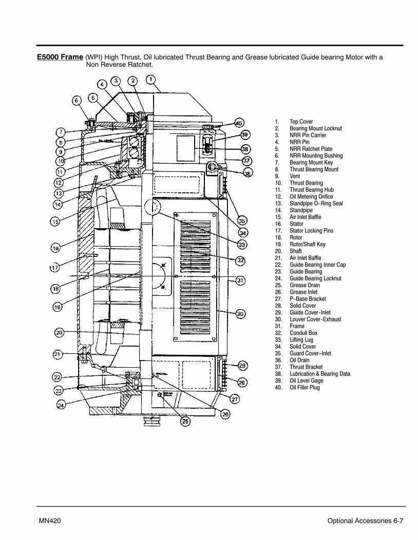
Optional Accessories 6-7MN420
E5000 Frame (WPI) High Thrust, Oil lubricated Thrust Bearing and Grease lubricated Guide bearing Motor with a Non Reverse Ratchet.
1. Top Cover2. Bearing Mount Locknut3. NRR Pin Carrier4. NRR Pin5. NRR Ratchet Plate6. NRR Mounting Bushing7. Bearing Mount Key8. Thrust Bearing Mount9. Vent10. Thrust Bearing11. Thrust Bearing Hub12. Oil Metering Orifice13. Standpipe O-Ring Seal14. Standpipe15. Air Inlet Baffle16. Stator17. Stator Locking Pins18. Rotor19. Rotor/Shaft Key20. Shaft21. Air Inlet Baffle22. Guide Bearing Inner Cap23. Guide Bearing24. Guide Bearing Locknut25. Grease Drain26. Grease Inlet27. P-Base Bracket28. Solid Cover29. Guide Cover-Inlet30. Louver Cover-Exhaust31. Frame32. Conduit Box33. Lifting Lug34. Solid Cover35. Guard Cover-Inlet36. Oil Drain37. Thrust Bracket38. Lubrication & Bearing Data39. Oil Level Gage40. Oil Filler Plug

6-8 Optional Accessories MN420
E5000 Frame (WPI) Extra High Thrust, Oil lubricated Thrust and Guide bearing Motor with a Non Reverse Ratchet.
1. Top Cover2. Bearing Mount Locknut3. NRR Pin Carrier4. NRR Pin5. Bearing Mount Key6. NRR Ratchet Plate7. NRR Mounting Bushing8. Thrust Bearing Mount9. Vent10. Thrust Bearing11. Thrust Bearing Cooling Coils12. Thrust Bearing Pre-Load Springs13. Oil Metering Orifice14. Thrust Bearing Hub15. Standpipe O-Ring Seal16. Standpipe17. Air Inlet Baffle18. Stator19. Stator Locking Pins20. Rotor21. Rotor/Shaft Key22. Shaft23. Air Inlet Baffle24. Guide Bearing Shaft Sleeve25. Guide Bearing Inner Cap26. Inner Cap O-Ring Seal27. Vent28. Guide Bearing29. Oil Metering Plate30. Guide Bearing Locknut31. Oil Metering Orifice32. Standpipe O-Ring Seal33. Standpipe34. Oil Drain35. Oil Level Gage36. P-Base Bracket37. Solid Cover38. Guard Cover-Inlet39. Oil Filler Plug40. Louver Cover-Exhaust41. Conduit Box42. Frame43. Lifting Lug44. Solid Cover45. Guard Cover-Inlet46. Oil Drain47. Lubrication & Bearing Data48. Oil Level Gage49. Thrust Bracket50. Oil Filler Plug

Optional Accessories 6-9MN420
E5000 Frame Spherical Roller Thrust Bearing Assembly Fixture.

6-10 Optional Accessories MN420
E5000 Frame Grease Lubricated Angular Contact Thrust Bearing
* The Heavy (Thick) side of the Outer Race is to be positioned as shown.
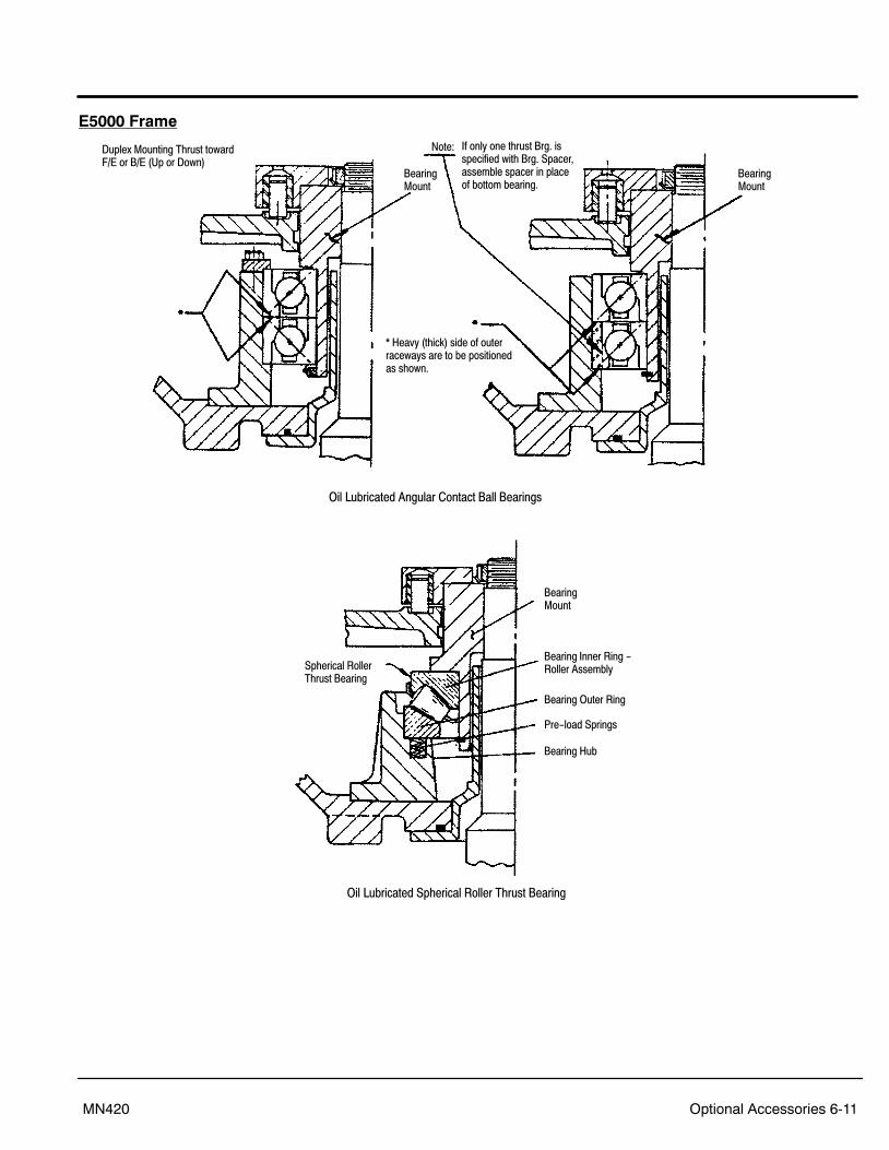
Optional Accessories 6-11MN420
E5000 Frame
Duplex Mounting Thrust towardF/E or B/E (Up or Down)
If only one thrust Brg. isspecified with Brg. Spacer,assemble spacer in placeof bottom bearing.
Note:
BearingMount
* Heavy (thick) side of outer raceways are to be positionedas shown.
BearingMount
Oil Lubricated Angular Contact Ball Bearings
Bearing Inner Ring -Roller Assembly
BearingMount
Bearing Outer Ring
Pre-load Springs
Bearing Hub
Spherical Roller Thrust Bearing
Oil Lubricated Spherical Roller Thrust Bearing

6-12 Optional Accessories MN420
E5000 Frame
Typical Weather Protected Type Ii And Low Noise Enclosure

Baldor District Offices

2009 Baldor Electric CompanyMN420
Printed in USA8/12
P.O. Box 2400 Fort Smith, AR 72902−2400 USA Ph: (1) 479.646.4711, Fax: (1) 479.648.5792www.baldor.com