aalborg universitet a cosine similarity based centralized
TRANSCRIPT

Aalborg Universitet
A Cosine Similarity-Based Centralized Protection Scheme for DC Microgrids
Mohanty, Rabindra; Sahoo, Subham; Pradhan, Ashok Kumar; Blaabjerg, Frede
Published in:I E E E Journal of Emerging and Selected Topics in Power Electronics
DOI (link to publication from Publisher):10.1109/JESTPE.2021.3060587
Creative Commons LicenseCC BY 4.0
Publication date:2021
Document VersionAccepted author manuscript, peer reviewed version
Link to publication from Aalborg University
Citation for published version (APA):Mohanty, R., Sahoo, S., Pradhan, A. K., & Blaabjerg, F. (2021). A Cosine Similarity-Based CentralizedProtection Scheme for DC Microgrids. I E E E Journal of Emerging and Selected Topics in Power Electronics,9(5), 5646-5656. https://doi.org/10.1109/JESTPE.2021.3060587
General rightsCopyright and moral rights for the publications made accessible in the public portal are retained by the authors and/or other copyright ownersand it is a condition of accessing publications that users recognise and abide by the legal requirements associated with these rights.
? Users may download and print one copy of any publication from the public portal for the purpose of private study or research. ? You may not further distribute the material or use it for any profit-making activity or commercial gain ? You may freely distribute the URL identifying the publication in the public portal ?
Take down policyIf you believe that this document breaches copyright please contact us at [email protected] providing details, and we will remove access tothe work immediately and investigate your claim.
Downloaded from vbn.aau.dk on: November 23, 2021

A Cosine Similarity Based Centralized ProtectionScheme for DC Microgrids
Rabindra Mohanty, Member, IEEE, Subham Sahoo, Member, IEEE, Ashok Kumar Pradhan,Senior Member, IEEE and Frede Blaabjerg, Fellow, IEEE
Abstract—Unlike the phasor measurement based protection inAC systems, the protection of DC systems deals with complexfault transients which mandates the isolation of the faultedsegment within few milliseconds as continued fault current leadsto overheating issue in power electronic converters. To this end,several works have been suggested based on unit and non-unit protections for DC microgrids. Threshold selection andprotection coordination are the challenges associated with non-unit protection. Similarly, communication delay and link failurelimit the application of unit protection. To address these issues,this paper presents a robust centralized protection scheme forDC microgrids, which is resilient to communication delay andlink failure. It uses current of each line segment to computethe similarity of current change at both ends of the linesegment to derive the protection decision. To overcome thecommunication failure from one end of the line segment or evenfrom multiple segments, the proposed method uses data fromadjacent segments to derive the protection decision correctly.Using PSCAD/EMTDC environment, the performance of theproposed method is evaluated for various cases and comparedwith available techniques. Finally, the accuracy of the protectionalgorithm is validated under experimental conditions.
Index Terms—Centralized protection, communication, cosinesimilarity, DC microgrid, fault analysis.
I. INTRODUCTION
W ITH advancement in power electronic converters andcommunication infrastructure, microgrid technologies
promote the integration of distributed generation (DG) withenergy storage sources (ESSs) to provide efficient and qualitypower to customers [1]. Today, DC microgrids have emergedas a promising architecture with majority of electronic loadsconsuming DC power and operability of DC producing renew-able sources like photovoltaic (PV) array, fuel cell and ESSs.DC mains and feeders reduce the number of conversion stages,as compared to AC and improve the efficiency [2]. Withoutsynchronization and reactive power control requirements, op-eration of multiple parallel power electronic converter inter-
This work was supported in part by Energy Area of Advance at ChalmersUniversity of Technology, Sweden and in part by THE VELUX FOUNDA-TIONS under the VILLUM Investigator Grant – REPEPS (Award Ref. No.:00016591).
R. Mohanty is with the Division of Electric Power Engineering,Chalmers University of Technology, Gothenburg, Sweden 41296 (e-mail:[email protected])
S. Sahoo and F. Blaabjerg are with the Department of Energy Technology,Aalborg University, Aalborg East, 9220, Denmark (e-mail: [email protected] [email protected])
A. K. Pradhan is with the Department of Electrical Engineering, In-dian Institute of Technology Kharagpur, India 712302 (e-mail: [email protected])
faced renewable energy source (RES) becomes an easy task inDC microgrids as compared to the AC counterparts [3].
One of the primary challenges in DC microgrids is the lackof an effective protection solution [4]. With the occurrenceof a fault, the DC-link capacitor of the power electronic con-verter discharges rapidly causing the DC bus voltage to dropsharply. Further, the energy stored in the cable inductance alsodischarges through the freewheeling diodes of the convertersresulting in a high magnitude fault current within a very shortinterval of time [5]. The converters operate as uncontrolledrectifiers (forward biasing of anti-parallel diodes) during faultconditions with the fault current still being fed from the inputside of the converter [6]. This may cause an unstable operationof the system and even damage the power semiconductorswitches in the converters unless the fault is cleared.
The existing protection schemes in DC microgrid can becategorized into non-unit and unit protections. Local measure-ment based non-unit protection schemes are presented for DCmicrogrids in [7]–[9], which do not require communication.However, its performance is influenced by factors such asrequirement of high bandwidth measurement devices [7],selection of thresholds [8] and can be accommodated onlyfor long distance DC line based systems [9]. Additionally,these schemes do not guarantee selectivity. On the otherhand, unit protection schemes exploit data from both endsof the line to be protected by overcoming the abovemen-tioned issues. Regardless of its advantages, high resistancefault could be an issue for current differential [10], [11] andcurrent directional [12] based unit protection schemes. Theperformance of the differential scheme is highly dependenton the current threshold, since the operating current may notexceed it during high resistance fault. Similarly, the directionof fault current during high resistance fault does not alter,as the pre-fault current can be more than the faulted currentunder heavy loading condition. In addition, communicationdelay and communication link failure limit the application ofunit protection schemes.
Intelligent electronic devices (IEDs) are used for protectionand automation with the support of IEC 61850 protocol[13]. Since IEC 61850 is known for its flexibility due toits capability of decoupling domain-specific models from thecommunication stack, it has been adopted as an internationalcommunication medium to monitor, control and measure thephysical processes in a microgrid. A centralized protectionscheme compatible with IEC 61850 protocol has the capabilityto provide promising solution for microgrids, that can dealwith the above stated issues associated with both non-unit and
Central IED
(HMI)
ax
Cde
Cdg Cdf
Cdd Cdb
Utility
grid230 V
PV Array
Battery
e d b a c
fg
Load Load Load
DC cable
Solid state circuit breaker (SSCB)xx
Hall sensor
Communication link between sensor and IED
Communication link between IED and SSCB
DCUIEC 61850
IEC 61850
Ethernet 10/100 MbEthernet 10/100 Mb
GPS
ed
2 km0.8 km
3 km1.5 km
0.3 km
0.2 km
de db
df
fd
fggf
bd ba
F1 F2
ab ac caR1+jω1L1 R2+jω2L2
idb ibd
CdaCdc
DCU
DCU
DCU Data concentrator unit
Ethernet
VSC
0.7 km11 kV/33 kV0.415 kV/11kV
Distribution
transformerSubstation
transformer
630 kVA 5 MVA
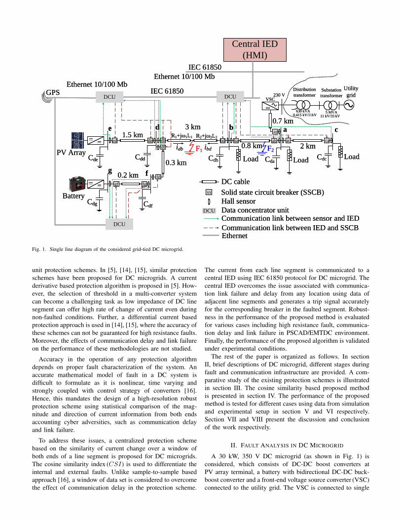
Fig. 1. Single line diagram of the considered grid-tied DC microgrid.
unit protection schemes. In [5], [14], [15], similar protectionschemes have been proposed for DC microgrids. A currentderivative based protection algorithm is proposed in [5]. How-ever, the selection of threshold in a multi-converter systemcan become a challenging task as low impedance of DC linesegment can offer high rate of change of current even duringnon-faulted conditions. Further, a differential current basedprotection approach is used in [14], [15], where the accuracy ofthese schemes can not be guaranteed for high resistance faults.Moreover, the effects of communication delay and link failureon the performance of these methodologies are not studied.
Accuracy in the operation of any protection algorithmdepends on proper fault characterization of the system. Anaccurate mathematical model of fault in a DC system isdifficult to formulate as it is nonlinear, time varying andstrongly coupled with control strategy of converters [16].Hence, this mandates the design of a high-resolution robustprotection scheme using statistical comparison of the mag-nitude and direction of current information from both endsaccounting cyber adversities, such as communication delayand link failure.
To address these issues, a centralized protection schemebased on the similarity of current change over a window ofboth ends of a line segment is proposed for DC microgrids.The cosine similarity index (CSI) is used to differentiate theinternal and external faults. Unlike sample-to-sample basedapproach [16], a window of data set is considered to overcomethe effect of communication delay in the protection scheme.
The current from each line segment is communicated to acentral IED using IEC 61850 protocol for DC microgrid. Thecentral IED overcomes the issue associated with communica-tion link failure and delay from any location using data ofadjacent line segments and generates a trip signal accuratelyfor the corresponding breaker in the faulted segment. Robust-ness in the performance of the proposed method is evaluatedfor various cases including high resistance fault, communica-tion delay and link failure in PSCAD/EMTDC environment.Finally, the performance of the proposed algorithm is validatedunder experimental conditions.
The rest of the paper is organized as follows. In sectionII, brief descriptions of DC microgrid, different stages duringfault and communication infrastructure are provided. A com-parative study of the existing protection schemes is illustratedin section III. The cosine similarity based proposed methodis presented in section IV. The performance of the proposedmethod is tested for different cases using data from simulationand experimental setup in section V and VI respectively.Section VII and VIII present the discussion and conclusionof the work respectively.
II. FAULT ANALYSIS IN DC MICROGRID
A 30 kW, 350 V DC microgrid (as shown in Fig. 1) isconsidered, which consists of DC-DC boost converters atPV array terminal, a battery with bidirectional DC-DC buck-boost converter and a front-end voltage source converter (VSC)connected to the utility grid. The VSC is connected to single

TABLE IFAULT CURRENT RESPONSE OF CONVERTERS IN DC MICROGRID
PG faultDC faultcurrent response VSC Boost
converterBuck
converterBuck-boostconverter
Stage 1 Yes Yes Yes YesStage 2 Yes Yes Yes YesStage 3 Yes Yes No No
phase of low voltage side of distribution transformer of 630kVA, 50 Hz, 0.415/11 kV. Finally, it is connected to the maingrid via a substation transformer of 5 MVA, 50 Hz, 11/33kV. Loads in the microgrid are primarily supplied by localPV arrays and under heavy loading conditions, the remainingpower is extracted from the grid. On the other hand, converterinterfaced with battery operates in voltage-controlled mode toregulate generation-demand imbalance during islanded modeof operation. The capacitance shown at each bus is the equiva-lent of DC link capacitor and cable as Cdx, where the subscriptx represents the bus number. The front-end VSC maintainsthe voltage at the point of common coupling (PCC) for gridconnected mode of operation. The PV arrays inject maximumpower into the grid with the help of a maximum power pointtracking (MPPT) control strategy. Two cascaded PI controlloops create a modulation signal in a complementary fashion tocontrol the switches in bidirectional DC-DC converter whichoperates in voltage controlled mode.
During a fault on the DC side, the transient response affectsthree counterparts; such as Stage 1: capacitor discharge ornatural response, Stage 2: freewheeling diode operation,and Stage 3: current fed from the grid. A detailed responsein time domain of the nonlinear circuit is analyzed for differenttime periods in [6], [17]. The occurrence of these stages de-pend on the converter topology and the type of fault [6]. TableI provides the stages of transient response for VSC and DC-DC converters during pole-to-ground (PG) faults in a unipolarDC microgrid. It is observed that Stage 1 and Stage 2are present in all cases during fault. The protection systemis expected to operate within the rise time of current (duringStage 1) to protect the switches in the converters fromoverheating stress in Stage 2 and Stage 3.
Several communication protocols are developed to exchangethe information between IEDs and power equipment in amicrogrid. In electrical substation, distributed network pro-tocol (DNP3), Modbus TCP/IP and protocols compliant withIEC 61850 are widely used. The IEC-61850 standard is part ofthe IEC technical committee 57 (IEC-TC-57) that deals withinformation model and logical nodes (LNs) including DGs,electrical connection points, controllers, generators, powerconverters, measurement and protection devices [18]. IEC61850 features include data modeling, reporting, fast trans-fer (GOOSE and GSSE), setting groups, sampling data value,command configuration and data storage. The data object andattributes of IEC 61850 monitor the measurement, breakerstatus and setting group status in the considered DC microgridin Fig. 1.
III. COMPARATIVE EVALUATION OF EXISTINGPROTECTION SCHEMES
The current derivative ( didt ) based protection is simple andcomputationally effective solution for DC microgrids [5],[8], [19]. Such methods take protection decision within fewmilliseconds. However, the high-frequency switching ripplescomplicate the trip decision of current derivative based pro-tection methods. Fig. 3 shows different ripple frequencies andmagnitudes of current for various switching frequencies Ns atthe output of a DC-DC buck converter. For 4 kHz sampling,the magnitudes of current gradient are 18 A/250 µs and 32A/250 µs for Ns=5 kHz and Ns=1.5 kHz respectively. Thesevalues are significantly high, which can easily exceed thethresholds.
IL
tDCM CCM
TsDTs DTs Ts
Averaging
window
Fig. 2. CCM/DCM operation modes for a DC-DC boost converter.
Furthermore as shown in Fig. 2, DCM/CCM mode areprimarily dependent on the loading condition in the output,where the converter either operates at DCM or CCM withrespect to the critical Rcrit value. Usually, the existing pro-tection mechanisms to detect a fault are based on averagingmechanism for signals which does not contain any switchingripples from the sources, since they have been formulated forstandard DC supplies. However, when the said fault detectionphilosophies are tested for power electronic converters withswitching ripples in the current, the following issues arise:
• the rate of change in current is not solely dependent onthe fault but also dependent on other factors such asswitching frequency, variable loading condition, voltagelevels, etc.
• the design of averaging window with a fixed thresholdto generate a decision under faults may be tricky (asshown in Fig. 2), since the average values could vary forDCM/CCM modes (under different loading conditions),different window sizes, etc. As a result, it could oftenlead to false tripping of converters for a fixed thresholdaveraging mechanism to detect faults.
0 0.1 0.2Time (s)
0
50
100
150
200
Cu
rren
t (A
)
Ns = 5000 Hz
Ns = 0 Hz; without diode
Ns = 1500 Hz
Fig. 3. Current response of DC-DC buck converter with different switchingfrequencies Ns.

TABLE IICOMPARATIVE ASSESSMENT OF EXISTING PROTECTION TECHNIQUES
Protection methods Work done Remarks
Methods based on didt
[5], [8], [19]
- Low resistance fault is detected by currentderivative.- High resistance fault detected by second orderderivative and current differential.
- Requires both voltage and current measurements.- Each line segment needs two IEDs at both endsto derive the protection decision.- Vulnerable to non-fault disturbance that causeshigher current derivatives.- IED coordination is not discussed in local databased protections.
Superimposed currentbased unit protection [20]Method based onsimilarity index [16]
- Superimposed current at both ends of the linesegment.- Cosine similarity of the transient waveformdistinguishes the internal and external faults.
- Method needs two IEDs [20] and one IED [16]in each line segment to be protected.- The superimposed component and similarity indexcannot be derived for a communication link failure.
Centralized protection [14], [15] - Current differential and moving averagebased protection.
- The current differential does not workfor communication link failure.- Communication delay causes the maloperationof differential technique for external faults.
Proposed protection scheme- Cosine similarity index of two independentdata windows of average di
dt.
- Validated in experimental setup.
- Current measurement only.- One central IED is required insteadof IED at each line segments.- Robustness towards communication delayand link failure.- The protection decision is unaffectedin presence of ripples due to high-frequencyswitching and for high resistance fault.
In the microgrid with short line lengths, the didt of adjacent
segments may exceed the predefined threshold values. Al-though, the peak depends on the corresponding bus voltage andinductance of the faulted path, the local data based protectionusing current derivative operates at the moment the derivativeexceeds the predefined threshold irrespective of the peak value.For example, a fault in the middle of the line segment-fd (referFig. 1) causes the di
dt at SSCB-gf and SSCB-fd above thethreshold (25 A/250 µs) as shown in Fig. 4. Thus, local databased di
dt fails to identify the correct faulted section resultinginto a selectivity issue. The above mentioned problem is moreprominent in case of small capacitor (or no capacitor), whichis present between the buses.
The selectivity issue in local data based technique is solvedusing communication assisted current differential, current di-rectional and centralized protections in DC microgrid. Highresistance fault is a problem for current differential anddirectional protection schemes. For example, the operatingcurrent (Idiff) in the current differential technique goes belowthe threshold for fault resistance more than 5.5 Ω, as evidentfrom Fig. 5. Similarly, the direction of current has not changedduring the fault with fault resistance more than 5 Ω, as shownin Fig. 6. As a result, such faults cannot be identified correctly.
0.48 0.485 0.49 0.495 0.5 0.505 0.51 0.515 0.52
Time (s)
-50
0
50
100
150
200
250
di/
dt
(A
/250
s)
digf
/dt
difd
/dt
Threshold
Fig. 4. Current derivatives at SSCB-gf and SSCB-fd for the fault in linesegment-fd.
1 2 3 4 5 6 7 8 9 100
10
20
30
Fig. 5. Current difference during high resistance internal fault.
Note that the rated current for a 30 kW, 350 V DC system is85.7 A. The fault resistance that causes the current less thanthe rated value is considered as high resistance fault. In thiscase, the current of 85.7 A corresponds to 4 Ω. Thus, the faultresistance of 5 Ω or more is considered as high resistancefault.
0.48 0.5 0.52 0.54 0.56 0.58 0.6Time (s)
-50
0
50
Cu
rren
t (A
)
Rf = 2 R
f = 5 R
f = 10
ibd
idb
Fig. 6. Currents of both ends during high resistance fault F1.
Communication delay (εn) results in maloperation of com-munication based protections schemes such as differentialscheme during an external fault. To illustrate this issue moreclearly, a pole-to-ground fault is created in line segment-abin Fig. 1 (considered as an external fault to the segment-bd),the current idb and ibd are observed, and their sum is plottedin Fig. 7. The ibd is communicated with a time delay, εt = 1ms with respect to idb. In such a case, the current difference

enters into operating region for a certain period of time asshown in Fig. 7. The threshold of the current differential ina DC microgrid is considered as ηIn [21], where η is thereliability coefficient whose value is in between 6% to 20%and In is the nominal current of the line segment, i.e. 85.7 Ain this case. Under these circumstances, the proposed methodsin [14], [15], [21] will maloperate.
id
0.48 0.5 0.52 0.54 0.56 0.58 0.6
Time (s)
-5
0
5
10
i db +
ib
d (
A)
With communication delay
No communication delay
Misoperation
Threshold
Operating region
External
fault inception
No operating region
Fig. 7. Current differential with and without communication delay during afault in adjacent line a-b.
The sign of didt has the inherent capability of distinguishing
faults in forward and reverse directions. The didt is positive for
forward fault and negative for reverse fault, provided the pre-fault power flow is in forward direction. However, the signof di
dt needs to be communicated to the remote end (and vice-versa) to identify the internal fault which requires communi-cation link, similar to unit protection. In summary, the localdidt based protections without communication have issues withthreshold setting and IEDs coordination. The communicationbased unit protections are associated with issues like commu-nication failure and delay. Similarity index based protectionmethod in [16] is not evaluated for communication link failure.In addition, it needs at least one IED for each line segmentin the DC microgrids which increases the cost. All the issueswith the existing protection strategies are provided in Table II.Furthermore, the advantages behind employing the proposedstrategy is also detailed in the same table.
IV. PROPOSED PROTECTION SCHEME
The DC microgrid considered in this work is shown inFig. 1. The microgrid is divided into different protectionsegments and each segment consists of a solid-state circuitbreaker (SSCB) at each end. A central IED is installed forthe entire microgrid. The cyber layer, shown in Fig. 1, isrealized using SimEvents based realistic communication modelto simulate all the intermittent parameters associated with thecommunication network [22]. Currents of both ends of a linesegment are communicated to the IED (highlighted in Fig. 1)and the rate of change of current at each end is obtained.
A. Fault detection
The collected line currents at IED are sampled at a rateof 4 kHz. A disturbance index (h) is calculated using currentinformation from the following relation
h =1
N∆t
(N∑n=1
|in+1 − in|
)(1)
where in corresponds to sample value of current for nth
instant with N = 4 as four samples in 1 ms, ∆t is thesampling interval. The absolute value of the current differenceis considered in (1) to monitor the magnitude change only.When h > ζ (threshold), a fault is ensured; else, it suggests anormal condition. The threshold ζ is calculated as:
ζ =1
N∆t
(N∑n=1
|in+1 − in|
)=
1× 5A
4× 250× 10−6s= 5000A/s
(2)Considering high security of IED operation
∑Nn=1|in+1 − in|
= 5 A is set, where∑Nn=1|in+1 − in| represents the sum of
four consecutive sample-to-sample differences. It is to be notedthat the disturbance index becomes high even for load changeor any other switching phenomena. Fig. 8 shows the currentresponse and Nh∆t for a sudden change in load (which mayconfuse relay with fault) as h exceeds ζ. This is similar to afault detector in available numerical relays which triggers thenext step on the decision process.
Fig. 8. Change in current and hN∆t with increase in load.
B. Current response during an internal faultIn Stage 1 of fault analysis, the RLC response of the DC
line current idb at bus-d in frequency domain during F1 canbe written as:
idb(s) =
Vdd(0)
L1+ idb(0)
s2 +R1
L1s+
1
L1Cd
(3)
where Vdd(0) is the voltage across the Cdd at bus-d and idb(0)is the current through L1 at the instant of fault inception. Faultcomponent of current in time domain is given by:
iF1
db (t) =Vdd(0)
L1(m2 −m1)
(e−m1t − e−m2t
)+
idb(0)
m2 −m1
(−m1e
−m1t +m2e−m2t
) (4)
where m1 = -α1+√α21 − ω2
0 , m2 = -α1-√α21 − ω2
0 and, α1
= R1/2L1, ω1 =
√1
L1Cdd− (
R1
2L1)2 and ω0 =
√α21 + ω2
1 .
The time derivative of (4) at t = 0+ at the instant of faultinception will be:
didb(t)
dt=Vdd(0)
L1− 2α1idb(0) (5)
Using (5), it can be concluded that the rate of change of currentdepends on the initial conditions of voltage across the DC linkcapacitor and line current just before the fault.

In a similar way at bus-b, for the fault F1, the rate of changeof line current ibd will be:
dibd(t)
dt=Vdb(0)
L2+R2
L2ibd(0) (6)
Remark I: As a convention with the direction of currents asshown in Fig. 1, it is clear that for internal fault F1, thedidb(t)
dtand
dibd(t)
dtare positive.
C. Current response during an external fault
Remark II: In case of an external fault F2 as shown in
Fig. 1, thedidb(t)
dtand
dibd(t)
dtare equal in magnitude as well
as their rate of changes. However, the sign will be opposite,
e.g.didb(t)
dt= -
dibd(t)
dt. Thus,
dibd(t)
dt=d(−idb(t))
dt=−didb(t)
dt
= −Vdd(0)
L1+R1
L1idb(0)
(7)
D. Cosine similarity index (CSI) based protection decision
In the above subsections, the direction of current duringtransient is analyzed. A simple threshold based protectiondecision is challenging for power-electronic converters dueto distortion and high-frequency ripples during transients.
Therefore, a window of 2 ms (i.e. 8 samples× 1
4000s) is
considered as shown in Fig. 9. The average of the rate ofchange of current in a window is obtained at each end of a linesegment. The alikeness of two data windows of both ends ofthe line segment is measured using cosine similarity. The ideaof cosine similarity used in the proposed method is analogousto the CSI of two non-zero vectors in a dot product, whichhas been widely used in data mining applications [23], [24].
Using two consecutive samples, the rate of changeof current is obtained in a window of 2 ms; 7
number ofdi
dtsamples in a window (in Fig. 9). where
didb(t)/dt = (idb(t2) − idb(t1))/(t2 − t1). For awindow of data set, X = average x1, x2, x3, ...x7 =
averagedidb1dt
,didb2dt
,didb3dt
, ...didb7dt
and Y = average
y1, y2, y3, ...y7 = averagedibd1dt
,dibd2dt
,dibd3dt
, ...dibd7dt
,
CSI can be calculated as below:
CSI =X.Y
|X| |Y |=
1
7
7∑n=1
xn.1
7
7∑n=1
yn∣∣∣∣17 7∑n=1
xn
∣∣∣∣ ∣∣∣∣17 7∑n=1
yn
∣∣∣∣ =
7∑n=1
xn.7∑
n=1yn∣∣∣∣ 7∑
n=1xn
∣∣∣∣ ∣∣∣∣ 7∑n=1
yn
∣∣∣∣(8)
For an external fault F2, X ≈7∑
n=1xn and Y ≈
7∑n=1
yn in the
line segment-db are positive and negative respectively, usingRemark II. However, for internal fault F1, both X and Y are
positive using Remark I. The similarity index output can besummarized by:
CSI =
+1, if, internal fault;−1, if, external;
(9)
window-1
idb(1) idb(2) idb(8)- - - - -
window of 2 ms
window-2
idb ibd = -idbd b
window-1
ibd(1) ibd(2) ibd(8)- - - - -
window of 2 ms
window-2
DC line
(X) (Y)
window-1
idb(1) idb(2) idb(8)- - - - -
window of 2 ms
window-2
idb ibd = -idbd b
window-1
ibd(1) ibd(2) ibd(8)- - - - -
window of 2 ms
window-2
DC line
(X) (Y)
Fig. 9. Independent data windows of both ends of the line segment-bd.
d b+idb +ibd
F1
DC line
SSCB SSCB
CdbCdd
Load
+ dIdb/dt
Average value (X) Average value (Y)
F2F3
Equivalent DC
networkEquivalent DC
network
+ dIdb/dt
- dIdb/dt
+ dIbd/dt
- dIbd/dt
+ dIbd/dt
window-1 window-1
F1
F2
F3
X = +ve
X = +ve
X = -ve
Y = +ve
Y = -ve
Y = +ve
d b+idb +ibd
F1
DC line
SSCB SSCB
CdbCdd
Load
+ dIdb/dt
Average value (X) Average value (Y)
F2F3
Equivalent DC
networkEquivalent DC
network
+ dIdb/dt
- dIdb/dt
+ dIbd/dt
- dIbd/dt
+ dIbd/dt
window-1 window-1
F1
F2
F3
X = +ve
X = +ve
X = -ve
Y = +ve
Y = -ve
Y = +ve
Fig. 10. Similarity of windows during internal and external faults.
The similarity of change in current at both ends of the linesegment, X and Y in (8) is shown in Fig. 10. For the internalfault (F1), CSI comes out to be +1 as both X and Y arepositive. However, CSI is -1 for the external faults (F2 andF3) as X and Y are opposite in sign. A detailed flowchart ofthe proposed protection scheme is provided in Fig. 11.
E. Communication link failure from one end of the faultedsegment
The fault F1 can not be confirmed from X and Y of linesegment-db if ibd is not communicated due to communicationlink failure as shown in Fig. 12. In this case, the IED uses thesimilarity of idb and iab to generate a trip decision. The tripsignal will be generated if |idb|−|iba| > |iload b|, where iload bis the rated load current at bus-b. Thus, the proposed methodperforms satisfactorily, even if communication link fails fromone end of a line segment.
F. Performance during multiple link failure
In case of multiple communication link failure, a fault canbe identified using the available information of rate of changeof current. For example, fault F1 can be identified using theCSI of idb and iab in case of communication failure of ibdand iba (refer Fig. 12). Under such circumstances, the adjacentsegment including the faulted one will be isolated. The tripdecision will be derived based on CSI = +1 and for the faultF1, the line segment-db and ab will be isolated.
It is worth notifying that the proposed method identifiesthe exact faulted segment when one communication channel

Data acquisition:
Currents from the line segments to IED
Yes
No
Internal fault(Trip)
Calculate h using (1)
Is h > ζ ?
External fault
Yes
No
DC network
Calculate CSI using (8) and (9)
Is CSI = +1 ? Is CSI = -1 ?
No
(No Trip)
Yes
Fault detection
Protection decision
Data acquisition:
Currents from the line segments to IED
Yes
No
Internal fault(Trip)
Calculate h using (1)
Is h > ζ ?
External fault
Yes
No
DC network
Calculate CSI using (8) and (9)
Is CSI = +1 ? Is CSI = -1 ?
No
(No Trip)
Yes
Fault detection
Protection decision
Fig. 11. Flow diagram of proposed protection algorithm.
ed
e d b a
de db bd ba ab
Central IED
ied ide idbibd
iabiba
+-++ -CSI = -1 CSI = -1
ed
e d b a
de db bd ba ab
Central IED
ied ide idbibd
iabiba
+-++ -CSI = -1 CSI = -1
F1
One channel fails
Two channels fail
ed
e d b a
de db bd ba ab
Central IED
ied ide idbibd
iabiba
+-++ -CSI = -1 CSI = -1
F1
One channel fails
Two channels fail
Fig. 12. Performance during communication links failure.
fails in the microgrid or two channels fail (one from eachnonadjacent segment). Further, when two or three channelsfail from adjacent segments, two segments are identified aspossible faulted segments. The selectivity of proposed methodduring communication link failure is listed in Table III.
For a fault on bus-b with communication link failure fromthe current sensor-bd, the CSI for line segment-ab and
TABLE IIISELECTIVITY WITH COMMUNICATION LINK FAILURE
Number of communicationchannel fails Segment isolation
No channel Only the faulted segmentOne channelTwo channels Faulted and the adjacent oneThree channels
segment-ed are -1 as the bus-b fault is external to thesesegments. In case of the sum is greater than maximum loadcurrent at the bus-b, then the IED sends trip signal to SSCB-bd. The fault is not yet cleared as the fault current is fed
from segment-ab (highdiabdt
). Consequently, the IED sends tripsignal to SSCB-ba and now the bus fault is cleared.
G. Performance during communication delay
There are different causes of communication delay, out ofwhich time-out error between communication devices [25]and non-synchronous current sampling are common [11]. Thechange in currents at both ends of the line segment during faultin the presence of communication delay can be expressed as:
X =1
7
7∑n=1
xn and, Y =1
7
7+εn∑n+εn=1
yn (10)
where εn denote the delayed sample number (in this case,one lost sample corresponds to a delay of 250 µs). Theproposed CSI is obtained using the average value of currentchange over a window of 2 ms rather than use of samplesin current differential technique. Thus, for communicationdelay (typically one or two samples, i.e. 0.5 ms for 4 kHzsampling), the window length takes care of it. It can be inferredthat the proposed strategy is resilient to communication delay.
H. Performance with noisy signal
The proposed CSI based protection method is immune tonoisy signals. The average over window reduces the noise levelin the signal to en extend and then the ratio of data windowsis not affected by the noise. With noise in the current signal,(8) becomes
CSI =Xnoise.Ynoise|Xnoise| |Ynoise|
=
1
7
7∑n=1
xn noise.1
7
7∑n=1
yn noise∣∣∣∣17 7∑n=1
xn noise
∣∣∣∣ ∣∣∣∣17 7∑n=1
yn noise
∣∣∣∣=
7∑n=1
xn noise.7∑
n=1yn noise∣∣∣∣ 7∑
n=1xn noise
∣∣∣∣ ∣∣∣∣ 7∑n=1
yn noise
∣∣∣∣(11)
From (11), it is clear that the combination of averaging andCSI computation for a corresponding window of di
dt resultsin accurate identification of fault even with noisy situation.
V. SIMULATION RESULTS
The proposed algorithm is tested for the 350 V DC mi-crogrid shown in Fig. 1. The system components and theirparameters are provided in Table IV. Using PSCAD/EMTDCsimulation, faults are created in different line segments anddata are acquired at a sampling rate of 4 kHz. The performanceof the method is tested for several cases, e.g. fault at differentlocations, communication link failure, high resistance fault andcommunication delay.

TABLE IVDC MICROGRID COMPONENTS AND PARAMETERS[17]
System voltage 350 V DCBase power 30 kWBattery 96 V, 0.4 kAhBattery DC-DC converter 10 kWSolar panel Vmp= 54.7V , Imp= 5.58A at STCPV converter 10 kWVSC connecting to utility grid 15 kWLoad Constant impedance load, 30 kWFault resistance 0 - 10 ΩDC link capacitor 2.5 mFCable parameters:Cross-section area 240 mm2
Resistance 0.125 Ω/kmInductance 0.232 mH/kmCapacitance 0.67 µF/km
0.499 0.5 0.501 0.502 0.503 0.504 0.50550
60
70Idb
0.499 0.5 0.501 0.502 0.503 0.504 0.505
Time (s)
-500
0
500
Cu
rren
t (A
)
Ibd
(a)
0.499 0.5 0.501 0.502 0.503 0.504 0.5050
2000
4000
6000di
db/dt
0.499 0.5 0.501 0.502 0.503 0.504 0.505
Time (s)
0
1
2
di(
t)/d
t (A
/s)
105
dibd
/dt
(b)
0.499 0.5 0.501 0.502 0.503 0.504 0.505
Time (s)
0
0.5
1
CS
I Fault
detectionFault
inception
(c)Fig. 13. For the internal fault F1 in the line segment-db (a) current at d andb sides (b) rate of change in current (c) the corresponding CSI .
A. Fault identification and protection decision
A pole-to-ground fault (F1) with a fault resistance of 5 Ω issimulated at 0.5 s in the middle of the line segment-bd (Fig. 1).The currents and their rate of change seen by the sensors atSSCB-db and SSCB-bd are shown in Fig. 13(a) and Fig. 13(b)respectively. As shown in Fig. 13(c), the average in the changeof current in a window at both ends (X and Y) is found to bepositive, which results in CSI to be +1 using (8).
Similarly, an external fault F2 (in the system in Fig. 1) witha fault resistance of 5 Ω is created at 0.5 s. The currents seenby sensors at SSCB-db and SSCB-bd are shown in Fig. 14(a).Further, it can be seen in Fig. 14(b) that the signs of changein current over a window at both ends of the line segment-dbare moving in opposite directions. As a result, it is confirmed
0.499 0.5 0.501 0.502 0.503 0.504 0.50552.4
52.6
52.8
Cu
rren
t (A
)
Idb
0.499 0.5 0.501 0.502 0.503 0.504 0.505
Time (s)
-70
-60
-50
Ibd
(a)
0.499 0.5 0.501 0.502 0.503 0.504 0.505
0
100
200di
db/dt
0.499 0.5 0.501 0.502 0.503 0.504 0.505Time (s)
-10000
-5000
0
di(
t)/d
t (A
/s)
dibd
/dt
(b)
0.499 0.5 0.501 0.502 0.503 0.504 0.505
Time (s)
-1
-0.5
0
CS
I
Fault
inceptionFault
detection
(c)Fig. 14. For the external fault F2 in the line segment-ab (a) current at d andb sides (b) rate of change in current (c) the corresponding CSI .
from Fig. 14(c) that CSI is -1.
0.499 0.5 0.501 0.502 0.503 0.504 0.505
Time (s)
-1
-0.5
0
CS
I
Load change
detectionSwitching
of load
Fig. 15. CSI for sudden load change.
The performance of the method is also tested for suddenchange in loading condition. The load is varied from 60% to110% of rated value at bus-b. The CSI is obtained as -1 asshown in Fig. 15. Therefore, no trip signal will be generated.
B. Performance during communication link failure
In case of one or two communication link failure, theproposed method is able to derive trip decision without losingproper selectivity. The influence of communication link failureis analyzed for various cases and the selectivity is provided inTable V.
C. Comparative assessment
1) Performance during high resistance internal fault: Highresistance fault is a problem for available centralized protec-tions based on current differential [11], [14], [15] and currentdirection based unit protection scheme [12] (refer section III).The proposed method uses the sign of the average of current

TABLE VSELECTIVITY DURING COMMUNICATION FAILURE FOR FAULT F1
Events Bus-d Bus-b Central IED RemarksNo communicationfailure idb is available ibd is available X and Y are positive and CSI = +1 Trip SSCB-db
and SSCB-bdOne end communicationfailure idb is not available ibd is available Apply KCL at bus-d, satisfied
the criteria as in section IV-ETrip SSCB-dband SSCB-bd
Both ends communicationfailure idb is not available ibd is not available Apply KCL at bus-d and b, satisfied
the criteria as in section IV-FTrip SSCB-dband SSCB-bd
Both ends and one end fromadjacent lines fails idb is not available ibd and iba are
not availableApply KCL at bus-d and a, satisfiedthe criteria as in section IV-F
Trip SSCBs atsegment-bd and ab
Load change in bus-b idb is available ibd is available idb, iab are positive andibd, iba are negative, CSI = -1 No trip signal
0.499 0.5 0.501 0.502 0.503 0.504 0.505
Time (s)
-1
-0.5
0
0.5
1
CS
I
Fault F1 with R
f= 10
Fault F2 with R
f= 10
Fault
inception
Fault
detection
Fig. 16. Performance of proposed method during high resistance fault.
change in a window, which is independent of the current di-rection at an instant. The performance of the proposed methodis evaluated for high resistance internal (F1) and external (F2)faults and the corresponding CSI are found to be +1 and -1respectively, as shown in Fig. 16.
0.499 0.5 0.501 0.502 0.503 0.504 0.505
Time (s)
-1
-0.5
0
CS
I
Fault
detection
Fault
inception
Fig. 17. CSI with communication delay during the fault in adjacent linea-b.
2) Performance in the presence of communication delay:At the middle of the line segment-ab, a PG fault F2 is createdwith fault resistance of 2 Ω at 0.5 s of simulation run. Acommunication delay of 1 ms is introduced in the currentsignal from the sensor at SSCB-bd of the line segment-db.Fort the fault F2 (Fig. 1, the proposed method obtains CSIusing (8) as -1 (Fig. 17) which confirms an external fault anddoes not allow to trip the SSCBs.
0.49 0.495 0.5 0.505Time (s)
0
200
400
600
Cu
rren
t
(A)
Idb
with noise of 3% S.D.
Ibd
with noise of 3% S.D.
Fault inception
at 0.5 s
Fig. 18. Current signal with noise at both ends of the segment-db during F1
in Fig. 1.
D. Performance of the proposed method with noisy signals
The performance of the method is tested for the currentsignal contaminated with uniform distribution noise with zeromean and a standard deviation (S.D.) of 3 % [17], [26]. Duringsuch a situation, currents idb and ibd for a fault F1 in the linesegment-db are shown in Fig. 18. With a fault resistance of 2Ω, a pole-to-ground fault is created at 0.5 s. The correspondingdidt with and without considering moving average window isshown in Fig. 19. The CSI is obtained (Fig 20) using the aver-age di
dt output from the windows at both ends of the segment-db. It is clearly observed that CSI is +1 during the faultwhich is correct. Therefore, the proposed method performswell even during noisy condition by using the averaging andCSI techniques.
0.49 0.495 0.5 0.505Time (s)
-2
0
2
4
di/
dt
(A
/s)
105
dibd
/dt
didb
/dt
0.494 0.495-101
104
0.494 0.495-10
010
di/dt with average window
output with noise
Fault inception
at 0.5 sdi/dt without average
window with noise
Fig. 19. didt
of the currents in Fig. 18 with and without moving averagewindow.
0.49 0.495 0.5 0.505
Time (s)
0
0.5
1
CS
I
Fault
inception
Fault
detection
Fig. 20. CSI obtained from the signals with noise.
VI. EXPERIMENTAL RESULTS
The proposed protection method has been experimentallyvalidated in a DC microgrid operating at a voltage referenceVdcref of 75 V with N = 2 buck converters, as shownin Fig. 21(a). Both the converters are tied radially to aprogrammable load (voltage-dependent mode). Each converteris controlled by dSPACE MicroLabBox DS1202 (target), withcontrol commands from the ControlDesk from the PC (host).

(a)
R1 = 1.022 Ω L1 = 2.557 mH
R2 = 0.177 Ω L2 = 0.443 mH
Cdc1
Rlo
ad = 5
0 Ω
F1
8 Ω
16.7 m 2.9 m
idb ibd
F2
8 Ω
+
-
+
-
Lse1
Cdc2
Lse2
Buck
converter I
Buck
converter II
Vdc1 Vdc2
(b)
(a)
R1 = 1.022 Ω L1 = 2.557 mH
R2 = 0.177 Ω L2 = 0.443 mH
Cdc1
Rlo
ad = 5
0 Ω
F1
8 Ω
16.7 m 2.9 m
idb ibd
F2
8 Ω
+
-
+
-
Lse1
Cdc2
Lse2
Buck
converter I
Buck
converter II
Vdc1 Vdc2
(b)
Fig. 21. (a) Experimental setup on a scaled-down DC microgrid (b) singleline diagram of the setup.
vdc1
idb
ibd
vdc2
ab
c d e
(a)
(b)
vdc1
idb
ibd
vdc2
ab
c d e
(a)
(b)
Fig. 22. (a) Performance of the proposed protection strategy in experimentalsetup for internal and external faults, (b) Zoomed version of rate of changeof current to calculate CSI during transition from external to internal fault.
A simplified single line diagram of the experimental setup isshown in Fig. 21(b).
Using the tie-line current measurements idb and ibd, theproposed CSI based protection scheme is designed in thecontrol platform to detect internal and external faults. Theexperimental testbed parameters are provided in Appendix.
As already established in simulated environment, it can beseen in Fig. 22(a) that the tie-line currents are opposite duringthe external fault F2 (as indicated in Fig. 21(b)) during the
event b after the switching pulses are initiated at event a.This validates the calculated CSI using (9) to be -1 duringexternal faults, which can be seen in the zoomed figure forthe rate of change of ti-line currents in Fig. 22(a) before eventc. Further during event c, an internal fault F1 (as indicated inFig. 21(b)) is subjected, where the currents rise in the samedirection. Prior to this fault, it can be seen in Fig. 22(b) thatCSI jumps to 1 to confirm the presence of an internal faultas per the proposed strategy. Further when the internal faultis removed during event d, it can be seen in Fig. 22(a) thatthe tie-line currents idb and ibd return back to CSI being -1.Finally, the converters are turned off during event e. Hence, therobustness of the proposed strategy is validated experimentallyfor both internal and external faults.
0 0.002 0.004 0.006 0.008 0.01
Time (s)
0
20
40
60
80
Cu
rren
t (A
)
idb
ibd
Fig. 23. High frequency ripples in currents from both converters in Fig. 21switched at a frequency of Ns = 2 kHz.
0 0.002 0.004 0.006 0.008 0.01
Time (s)
0
0.5
1
CS
I
Fault detection
Fault
inception
Fig. 24. Corresponding CSI for the study carried out in Fig. 23.
Further, the proposed method is also experimentally vali-dated for currents with lower switching frequency of 2 kHz.A pole-to-ground fault is created during no load at 0 s andthe currents from the DC-DC buck converters are capturedas shown in Fig. 23. Under these conditions, it can be seenthat the corresponding CSI moves to +1 as shown in Fig. 24,which establishes the robustness of the proposed strategy evenfor converters even with lower switching frequency.
VII. DISCUSSION
In the proposed method, the fault detection does not takemore than 1 ms as it uses 4 samples at a sampling frequency of4 kHz (using (1)). A window of 2 ms is used to calculate CSI ,thus the protection decision can be taken in 3 ms of the faultinception which is evident from the results. The average ofcurrent change over a window is considered to avoid the issuesassociated with communication delay and any spurious datain the signal. As an advantage, the proposed method identifiesthe exact faulted segment during a communication channelfails. Furthermore, the faulted segment along with an adjacentone are isolated in case of two or three channels fail. The

method can be applied to any DC microgrid including ring bus,grounded and ungrounded systems as it uses current signal ofeach line segment.
VIII. CONCLUSION
In this work, a centralized DC microgrid protection schemeis proposed. The similarity of rate of current change over awindow of both ends of the line segment identifies an internalfault. IEC 61850 protocol is realized for the communicationin DC microgrid application using SimEvents blocks. Theperformance of the protection scheme is tested for highresistance fault, communication delay and link failure. Theprotection decision is taken within 3 ms or even faster in caseof no delayed signals. This protection algorithm aids in powerelectronic based systems by providing an auxiliary signal toblock the switching pulses being supplied to converter. Ascompared to available protection schemes that use both voltageand current data, the proposed protection scheme entails aneconomic alternative, which employs only one central IED forentire microgrid and one current sensor for each end of a linesegment. Its performance is also validated under experimentalconditions for both internal and external faults, and foundaccurate.
APPENDIX
The considered system consists of two sources with theconverters rated equally for 600 W. It should be noted thatthe controller gains are consistent for each converter.Plant: Lsei= 3 mH, Cdci= 100 µF, Ns = 7.5 kHzController: Vdcref = 75 V, KH1
P = 1.92, KH1
I = 15, KH2
P =4.5, KH2
I = 0.08, Tsw = 5 kHz.
ACKNOWLEDGMENTThe authors would like to thank Prof. Tomislav Dragicevic
at Technical University of Denmark for initial comments,which has helped enhance the presentation of this paper.
REFERENCES
[1] R. Cuzner, “Does DC distribution make sense?,” IEEE Electr. Mag.,vol. 4, pp. 2–3, June 2016.
[2] S. Sahoo and S. Mishra, “A distributed finite-time secondary averagevoltage regulation and current sharing controller for DC microgrids,”IEEE Trans. Smart Grid, vol. 10, no. 1, pp. 282–292, 2019.
[3] V. Kumar, S. R. Mohanty, and S. Kumar, “Event trigger super twistingsliding mode control for DC micro grid with matched/unmatcheddisturbance observer,” IEEE Trans. Smart Grid, vol. 11, no. 5, pp. 3837–3849, 2020.
[4] D. Salomonsson, L. Soder, and A. Sannino, “Protection of low-voltageDC microgrids,” IEEE Trans. Power Del., vol. 24, pp. 1045–1053, July2009.
[5] S. Augustine, M. J. Reno, S. M. Brahma, and O. Lavrova, “Fault currentcontrol and protection in a standalone DC microgrid using adaptivedroop and current derivative,” IEEE Journal of Emerging and SelectedTopics in Power Electronics, available in early access, 2020.
[6] A. Meghwani, S. Chakrabarti, S. C. Srivastava, and S. Anand, “Analysisof fault characteristics in DC microgrids for various converter topolo-gies,” in 2017 IEEE ISGT-Asia, pp. 1–6, Dec 2017.
[7] X. Feng, L. Qi, and J. Pan, “A novel fault location method andalgorithm for DC distribution protection,” IEEE Trans. Ind. Appl.,vol. 53, pp. 1834–1840, May 2017.
[8] A. Meghwani, S. C. Srivastava, and S. Chakrabarti, “A non-unit pro-tection scheme for DC microgrid based on local measurements,” IEEETrans. Power Del., vol. 32, pp. 172–181, Feb 2017.
[9] S. Azizi, M. Sanaye-Pasand, M. Abedini, and A. Hasani, “A traveling-wave-based methodology for wide-area fault location in multiterminalDC systems,” IEEE Trans. Power Del., vol. 29, pp. 2552–2560, Dec2014.
[10] J. D. Park and J. Candelaria, “Fault detection and isolation in low-voltageDC-bus microgrid,” IEEE Trans. Power Del., vol. 28, pp. 779–787, Jan.2013.
[11] S. D. A. Fletcher, P. J. Norman, K. Fong, S. J. Galloway, and G. M. Burt,“High-speed differential protection for smart DC distribution systems,”IEEE Trans. Smart Grid, vol. 5, pp. 2610–2617, Sept 2014.
[12] A. A. S. Emhemed, K. Fong, S. Fletcher, and G. M. Burt, “Validation offast and selective protection scheme for an LVDC distribution network,”IEEE Trans. Power Del., vol. 32, pp. 1432–1440, June 2017.
[13] A. N. Alndreev, E. A. Patrashkin, and A. S. Zheltov, “Centralized relayprotection of power plants using iec-61850,” in 2018 International Multi-Conference on Ind. Eng. and Modern Tech., pp. 1–3, Oct 2018.
[14] V. Nougain, S. Mishra, and A. K. Pradhan, “MVDC microgrid protectionusing a centralized communication with a localized backup scheme ofadaptive parameters,” IEEE Trans. Power Del., vol. 34, pp. 869–878,June 2019.
[15] M. Monadi, C. Gavriluta, A. Luna, J. I. Candela, and P. Rodriguez,“Centralized protection strategy for medium voltage DC microgrids,”IEEE Trans. Power Del., vol. 32, pp. 430–440, Feb 2017.
[16] K. Jia, C. Wang, T. Bi, R. Zhu, and Z. Xuan, “Transient current wave-form similarity based protection for flexible DC distribution system,”IEEE Trans. Ind. Electr., vol. 66, pp. 9301–9311, Dec 2019.
[17] R. Mohanty and A. K. Pradhan, “Protection of smart DC microgrid withring configuration using parameter estimation approach,” IEEE Trans.Smart Grid, vol. 9, pp. 6328–6337, Nov 2018.
[18] S. Mohagheghi, J. Stoupis, and Z. Wang, “Communication protocolsand networks for power systems-current status and future trends,” inIEEE/PES PSCE, pp. 1–9, March 2009.
[19] T. Wang and A. Monti, “Fault detection and isolation in DC microgridsbased on singularity detection in the second derivative of local currentmeasurement,” IEEE Journal of Emerging and Selected Topics in PowerElectronics, available in early access, 2020.
[20] S. Ahmadi, I. Sadeghkhani, G. Shahgholian, B. Fani, and J. M. Guerrero,“Protection of LVDC microgrids in grid-connected and islanded modesusing bifurcation theory,” IEEE Journal of Emerging and Selected Topicsin Power Electronics, available in early access, 2019.
[21] A. Ameli, K. A. Saleh, A. Kirakosyan, E. F. El-Saadany, and M. M. A.Salama, “An intrusion detection method for line current differentialrelays in medium-voltage DC microgrids,” IEEE Trans. Inf. Foren. andSecur., vol. 15, pp. 3580–3594, 2020.
[22] R. Rana, S. Sahoo, S. Mishra, and J. C. H. Peng, “Performance validationof cooperative secondary controllers in autonomous AC microgridsunder communication delays,” in IEEE PESGM 2019, pp. 1–5, Aug2019.
[23] A. Singhal, “Modern information retrieval: A brief overview,” in IEEEEng. Bull., pp. 35–43, vol. 24, no. 4, Jan. 2001.
[24] P. N. Tan, M. Steinbach, and V. Kumar, “Introduction to data mining,”in IEEE Eng. Bull., pp. 500, ch. 8, MA, USA, 2001.
[25] N. Villamagna and P. A. Crossley, “A symmetrical component-based gpssignal failure-detection algorithm for use in feeder current differentialprotection,” IEEE Trans. Power Del., vol. 23, pp. 1821–1828, Oct 2008.
[26] J. G. Rao and A. K. Pradhan, “Power-swing detection using movingwindow averaging of current signals,” IEEE Trans. Power Del., vol. 30,pp. 368–376, Feb 2015.
Rabindra Mohanty (Member, IEEE) is currently a postdoctoral re-searcher in the division of Electric Power Engineering at Chalmers Universityof Technology, Gothenburg, Sweden. His research interests include powersystems protection, renewable energy integration, protection and control ofmicrogrids.
Subham Sahoo (Member, IEEE) is currently an Assistant Professorin the Department of Energy Technology, Aalborg University, Denmark.His research interests are control, optimization, and stability of microgrids,renewable energy integration, physics-informed AI tools for cyber-physicalpower electronic systems.
Ashok Kumar Pradhan (Senior Member, IEEE) is a Professor withthe Department of Electrical Engineering, Indian Institute of TechnologyKharagpur, India, since 2002. His research interests include Power SystemRelaying and Monitoring.
Frede Blaabjerg (Fellow, IEEE) is currently a Full professor in theDepartment of Energy Technology, Aalborg University, Denmark. His currentresearch interests include power electronics and its applications, such as inwind turbines, PV systems, reliability, harmonics, and adjustable speed drives.