a.5 uas maintenance, modification, repair, inspection ... 4... · table 1 shows the relationship of...
TRANSCRIPT
A.5 UAS Maintenance, Modification, Repair, Inspection, Training, and Certification Considerations
Task 4: Draft Technical Report of UAS Maintenance Technician Training Criteria and Draft Certification Requirements
6 Nov 2017
Final Report

ii
NOTICE
This document is disseminated under the sponsorship of the U.S. Department of Transportation in the interest of information exchange. The U.S. Government assumes no liability for the contents or use thereof. The U.S. Government does not endorse products or manufacturers. Trade or manufacturers’ names appear herein solely because they are considered essential to the objective of this report. The findings and conclusions in this report are those of the author(s) and do not necessarily represent the views of the funding agency. This document does not constitute FAA policy. Consult the FAA sponsoring organization listed on the Technical Documentation page as to its use.

iii
Legal Disclaimer: The FAA has sponsored this project through the Center of Excellence for Unmanned Aircraft Systems. However, the agency neither endorses nor rejects the findings of this research. The presentation of this information is in the interest of invoking technical comment on the results and conclusions of the research.

iv
Technical Report Documentation Page
Title: A.5 UAS Maintenance, Modification, Repair, Inspection, Training, and Certification Considerations – Task 4: Technical Report of UAS Maintenance Technician Training Criteria and Draft Certification Requirements
Report Date: 6 November 2017
Performing Organizations: Kansas State University (KSU), Embry-Riddle Aeronautical University (ERAU), Northland Community Technical College (NCTC), Montana State University (MSU)
Authors: Dr. Kurt Barnhart, Charles Nick, Zackary Nicklin, Caleb Scott, Dr. John Robbins, Mitch Geraci, Dr. Richard Stansbury, Dr. Doug Cairns, Kyle Rohan
Performing Organization Address: Kansas State University Sponsored Programs 2323 Anderson Ave, Suite 600 Manhattan, KS 66502
Embry-Riddle Aeronautical University 600 S. Clyde Morris Blvd Daytona Beach, FL 32114
Northland Community Technical College (NCTC) 13892 Airport Drive Thief River Falls, MN 56701
Montana State University (MtSU) 211 Montana Hall Bozeman, MT 59717
Sponsoring Agency Name and Address: U.S. Department of Transportation Federal Aviation Administration Washington, DC 20591

v
TABLE OF CONTENTS
1. Scope ........................................................................................................................................................ 1
2. Introduction ............................................................................................................................................. 2
3. Industry Best Practices ........................................................................................................................... 6 3.1 LITERATURE REVIEW .......................................................................................................................... 6 3.2 SURVEY ............................................................................................................................................... 7
4. Current Maintenance Practices ............................................................................................................. 9 4.1 NON-METALLIC MATERIALS ............................................................................................................ 10 4.2 CONTROL SYSTEMS (CS) ................................................................................................................... 11 4.3 SUPPORT EQUIPMENT ....................................................................................................................... 15 4.4 COMMUNICATION LINKS .................................................................................................................. 18 4.5 AUTOPILOT ....................................................................................................................................... 22 4.6 SOFTWARE ........................................................................................................................................ 23
5. The Gap Analysis .................................................................................................................................. 24 5.1 UAS MAINTENANCE SKILL CLASSES ................................................................................................ 25 5.2 STANDARDS OVERVIEW .................................................................................................................... 28 5.2.1 14 CFR PART 43 ............................................................................................................................. 28 5.2.2 14 CFR PART 65 ............................................................................................................................. 31 5.2.3 14 CFR PART 147............................................................................................................................ 32 5.3 INTERNATIONAL STANDARDS ........................................................................................................... 35
6. Recommendations ................................................................................................................................. 38 6.1 THE UNMANNED AIRCRAFT (UA) ..................................................................................................... 39 6.2 CONTROL STATIONS (CS) AND SUPPORT EQUIPMENT ..................................................................... 40 6.3 COMMUNICATION LINKS .................................................................................................................. 42 6.4 AUTOPILOT ....................................................................................................................................... 45 6.5 SOFTWARE ........................................................................................................................................ 46
7. Conclusion ............................................................................................................................................. 47
8. Bibliography .......................................................................................................................................... 50
Appendix A – UAS Maintenance Skill Class .......................................................................................... 52
Appendix B – Recommended UAS Skills ................................................................................................ 57
Appendix C – Gap Analysis of Part 43 ................................................................................................... 60
Appendix D – Gap Analysis of Part 65 ................................................................................................. 104
Appendix E – Gap Analysis of Part 147 ................................................................................................ 118
Appendix F – Gap Analysis Part-66 ...................................................................................................... 129
vi
LIST OF FIGURES
Figure 1 – UAS Components [6] ................................................................................................................................... 4 Figure 2 – High-Level Functional Block Diagram of the C2 System [10] .................................................................. 20 Figure 3 – Primary Communication Link Components ............................................................................................... 21 Figure 4 – Main autopilot interfaces [6] ...................................................................................................................... 22 Figure 5 – UAS Skill Chart ......................................................................................................................................... 27 Figure 6 – Applicability of Part 43 By Skill Class ...................................................................................................... 29 Figure 7 – Applicability of Part 43 to Skill Class 1 ..................................................................................................... 30 Figure 8 – Applicability of Part 65 to UAS Skill Classes ............................................................................................ 31 Figure 9 – Applicability of Part 147 to UAS Skill Classes .......................................................................................... 32 Figure 10 – Applicability of EASA Part-66 to UAS Skill Classes .............................................................................. 36 Figure 11 –UAS Skill Class Applicability to CFRs from Gap Analysis ..................................................................... 38 Figure 12 – Total Recommended Skills per Skill Class for CFR Part 147 .................................................................. 39

vii
LIST OF TABLES
Table 1 – A5 Work Breakdown Structure ..................................................................................................................... 1 Table 2 – UAS Components & In-depth Analysis ......................................................................................................... 5 Table 3 – Normal Procedures per UAS items [7] ........................................................................................................ 10 Table 4 – Control Station (CS) Categories .................................................................................................................. 12 Table 5 – Primary CS Components ............................................................................................................................. 12 Table 6 – Types of Launch Equipment ........................................................................................................................ 17 Table 7 – Types of Recovery Equipment .................................................................................................................... 18 Table 8 – Types of Miscellaneous Equipment ............................................................................................................. 18 Table 9 – Communication Link Elements ................................................................................................................... 19 Table 10 – Maintenance Skill Classes (See Appendix A – UAS Maintenance Skill Class for more details) .............. 25 Table 11 – Excerpt from Part 147 Analysis ................................................................................................................. 28 Table 12 – Primary Skills for CS and Support Equipment .......................................................................................... 40 Table 13 – Primary Skills ............................................................................................................................................ 44 Table 14 – UAS Maintenance Skill Class ................................................................................................................... 52 Table 15 – Recommended UAS Skills ........................................................................................................................ 57 Table 16 – Part 43 Gap Analysis Evaluation ............................................................................................................... 60 Table 17 – Part 65 Gap Analysis Evaluation ............................................................................................................. 104 Table 18 – Part 147 Gap Analysis Evaluation ........................................................................................................... 118 Table 19 – EASA Part-66 Gap Analysis Evaluation ................................................................................................. 129
viii
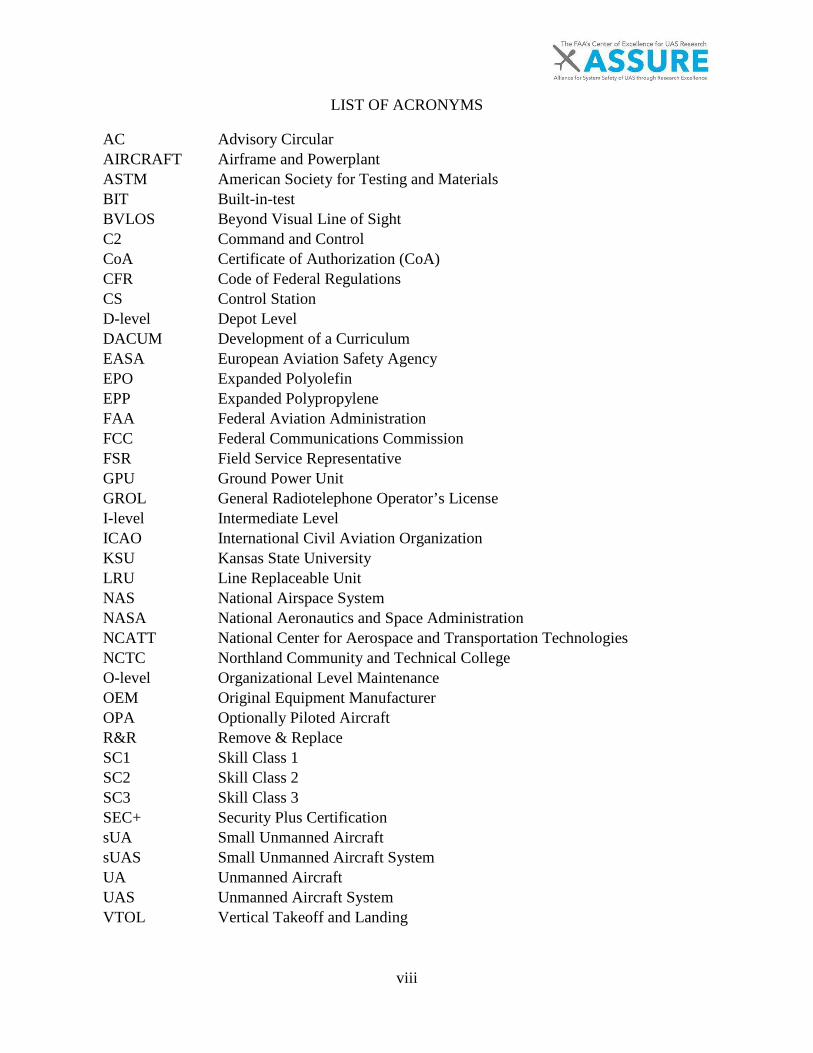
LIST OF ACRONYMS
AC Advisory Circular AIRCRAFT Airframe and Powerplant ASTM American Society for Testing and Materials BIT Built-in-test BVLOS Beyond Visual Line of Sight C2 Command and Control CoA Certificate of Authorization (CoA) CFR Code of Federal Regulations CS Control Station D-level Depot Level DACUM Development of a Curriculum EASA European Aviation Safety Agency EPO Expanded Polyolefin EPP Expanded Polypropylene FAA Federal Aviation Administration FCC Federal Communications Commission FSR Field Service Representative GPU Ground Power Unit GROL General Radiotelephone Operator’s License I-level Intermediate Level ICAO International Civil Aviation Organization KSU Kansas State University LRU Line Replaceable Unit NAS National Airspace System NASA National Aeronautics and Space Administration NCATT National Center for Aerospace and Transportation Technologies NCTC Northland Community and Technical College O-level Organizational Level Maintenance OEM Original Equipment Manufacturer OPA Optionally Piloted Aircraft R&R Remove & Replace SC1 Skill Class 1 SC2 Skill Class 2 SC3 Skill Class 3 SEC+ Security Plus Certification sUA Small Unmanned Aircraft sUAS Small Unmanned Aircraft System UA Unmanned Aircraft UAS Unmanned Aircraft System VTOL Vertical Takeoff and Landing

ix
EXECUTIVE SUMMARY
A protocol for Unmanned Aircraft Systems (UAS) maintenance technician certification requirements is essential for continued safety and airworthiness of this rapidly evolving technology. The Task 4 research activities described in this report consisted of a gap analysis, surveys, in-depth analyses of UAS specific systems (control stations, autopilot, software, etc.), and a detailed literature review to identify UAS maintenance skills.
There are three primary UAS industry specifications related to maintenance skills and training: 1) ASTM F2909-14 Standard Practice for Maintenance and Continued Airworthiness of Small Unmanned Aircraft Systems (sUAS), 2) the National Center for Aerospace and Transportation Technologies’ (NCATT) Standard Unmanned Aerial Systems Maintenance Technician Certification, and 3) the DACUM Research Chart for UAS Maintenance Technicians created by Northland Community Technical College (NCTC) which addresses curriculum subjects.
To better understand maintenance technician training certification requirements, varying levels of system taxonomy are needed for Unmanned Aircraft Systems (UAS). A 3-tier skill classification for training was developed by the authors of this report to implement a scalable UAS maintenance technician-training requirement. This approach was a direct answer to one of the research questions of A.5 regarding the need to delineate between different risk classes of UAS when determining maintenance and training requirements. Current 14 CFR regulations (Part 43, Part 65, Part 147) and European Aviation Safety Agency (EASA) Part-66 were used as a baseline to compare known UAS maintenance procedures using the newly developed 3-tier skill classification in order to identify gaps. This demonstrates the overlap in each skill class and identifies the missing requirements necessary to train a UAS maintenance technician.
The final list of recommended UAS maintenance technician training certification requirements are based on the results of the gap analysis, in-depth analysis reports, and industry standards. The review of 14 CFR Part 147 was prioritized in order to more easily define the specific recommended UAS skills to the existing curriculums listed in the three Part 147 Appendices B, C and D.
1
1. SCOPE
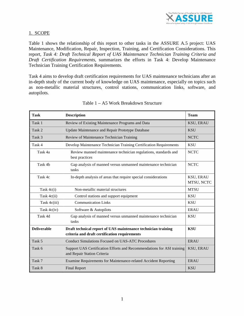
Table 1 shows the relationship of this report to other tasks in the ASSURE A.5 project: UAS Maintenance, Modification, Repair, Inspection, Training, and Certification Considerations. This report, Task 4: Draft Technical Report of UAS Maintenance Technician Training Criteria and Draft Certification Requirements, summarizes the efforts in Task 4: Develop Maintenance Technician Training Certification Requirements.
Task 4 aims to develop draft certification requirements for UAS maintenance technicians after an in-depth study of the current body of knowledge on UAS maintenance, especially on topics such as non-metallic material structures, control stations, communication links, software, and autopilots.
Table 1 – A5 Work Breakdown Structure
Task Description Team
Task 1 Review of Existing Maintenance Programs and Data KSU, ERAU
Task 2 Update Maintenance and Repair Prototype Database KSU
Task 3 Review of Maintenance Technician Training NCTC
Task 4 Develop Maintenance Technician Training Certification Requirements KSU
Task 4a Review manned maintenance technician regulations, standards and best practices
NCTC
Task 4b Gap analysis of manned versus unmanned maintenance technician tasks
NCTC
Task 4c In-depth analysis of areas that require special considerations KSU, ERAU MTSU, NCTC
Task 4c(i) Non-metallic material structures MTSU Task 4c(ii) Control stations and support equipment KSU Task 4c(iii) Communication Links KSU
Task 4c(iv) Software & Autopilots ERAU Task 4d Gap analysis of manned versus unmanned maintenance technician
tasks KSU
Deliverable Draft technical report of UAS maintenance technician training criteria and draft certification requirements
KSU
Task 5 Conduct Simulations Focused on UAS-ATC Procedures ERAU
Task 6 Support UAS Certification Efforts and Recommendations for ASI training and Repair Station Criteria
KSU, ERAU
Task 7 Examine Requirements for Maintenance-related Accident Reporting ERAU
Task 8 Final Report KSU

2
2. INTRODUCTION
Training maintenance technicians for the Unmanned Aircraft System (UAS) industry is a similar challenge to what was faced in the early days of aircraft maintenance about a century ago. When Frank Gardner received the first federal aircraft mechanic’s certificate in 1927, the aviation industry was moving rapidly with new innovations and technologies [1]. They faced the same questions the UAS industry faces today such as: How do you prepare maintenance personnel to effectively do their job while preventing maintenance-induced failures? In other words, how do we balance training with mission completion? What is the appropriate level of depth and complexity needed to instill the skills needed to serve as a UAS maintenance technician?
This report answers these questions and identifies the gaps between manned aviation and UAS aviation maintenance practices based on the current state of UAS maintenance industry as identified in the Task 3 Report, “Survey Results and Technical Review of UAS Maintenance Technician Training Standards.”
This report also identifies the key elements that comprise UAS maintenance for all types/sizes of UAS based on a new three-tier skill classification system (Refer to Appendix A – UAS Maintenance Skill Class). The new skill classification system identifies the unique considerations for non-metallic structures of UAS and defines the unique elements of UAS maintenance while benchmarking to manned aviation using a series of four in-depth analyses reports:
• Task 4c(i) Report: In-Depth Analysis of Non-Metallic Materials• Task 4c(ii) Report: In-Depth Analysis of Control Systems and Support
Equipment• Task 4c(iii) Report: In-Depth Analysis of Communication Links• Task 4c(iv) Report: In-Depth Analysis of Software and Autopilots
This report used many methods to acquire information. UAS industry experts completed multiple surveys and the research team reviewed current UAS industry standards. Industry standards reviewed for this research included NCATT Standards and ASTM F2909-14. The research team also identified and reviewed many other international UAS documents and standards. Refer to Section 3.1 for a detailed list of the standards reviewed.
Optionally piloted aircraft (OPA) were not included in this study since they contain both manned and unmanned systems in parallel negating some of the unique aspects of unmanned aircraft (UA). Most military UA’s produced up to 2006 were not included in this study due to the lack of access to historical data for these systems. Lastly, micro UAS were not included in this study due to the lack of maintenance tasks being performed on these UA today.
3
Three levels of maintenance activity, as historically and currently defined by the military, were reviewed for applicability for this study: Organizational (O-level), Intermediate (I-level) and Depot (D-level). Organizational maintenance is performed at the operational level traditionally using spare parts to replace damaged components or perform servicing tasks. Intermediate maintenance is performed in a more specialized facility that focuses on component repair, and more skilled maintenance procedures, which could include soldering, calibration, and more. Depot maintenance is traditionally performed at the Original Equipment Manufacturers’ (OEM) location or similarly equipped facility using highly specialized personnel, equipment, and processes not available to the prior two maintenance levels [2].
Consideration was also given to maintenance alterations identifying two primary candidates: structural repairs and wiring repairs. Both types of repairs have the potential to affect the weight and balance of the UA. Major and minor repairs for UAS also have the potential to impact weight and balance.
The FAA defines a major repair as the following, “(1) That, if improperly done, might appreciably affect weight, balance, structural strength, performance, power plant operation, flight characteristics, or other qualities affecting airworthiness; or (2) That is not done according to accepted practices or cannot be done by elementary operations [3].”
When considering repairing or replacing a propeller for a DJI rotorcraft, the above instructions still apply because if improperly performed, however elementary, the performance or flight characteristics can be affected. It is possible to lose the entire UA in a crash due to improper propeller installation, regardless if the instructions are overly basic and the activity is relatively easy to perform.
Another consideration for maintenance alterations affects the technical documentation used to perform operation and maintenance for a UAS. The ASTM F2911-14 standard details the requirements for a configuration management plan (see F2911-14 Section 5.1.7.1), “The sUAS manufacturer shall develop a configuration management plan to ensure that a standard configuration for each sUAS is established and maintained and to provide objective evidence of production conformance to specifications and continued effectiveness of the quality management system [4].” Although ASTM F2911-14 is a consensus standard, this requirement still applies to operations and maintenance because of the importance of understanding any configuration changes and/or modification that could affect operations and maintenance.
One of the questions that the A5 project aims to answer is whether there is a need to delineate between different risk classes of UAS when determining maintenance and training requirements. This question refers to a draft risk classification taxonomy proposed by the FAA for classifying UAS operations based on risk and kinetic energy. As discussed in this report, the research team ultimately recommends that classification based on risk, a combination of probability and impact effect, is not appropriate for aircraft maintenance technician certification, in which training is based on specific skills required to perform a task, not operational risk. It is possible to delineate risk after a system has been designed and tested, but not before [5].
4
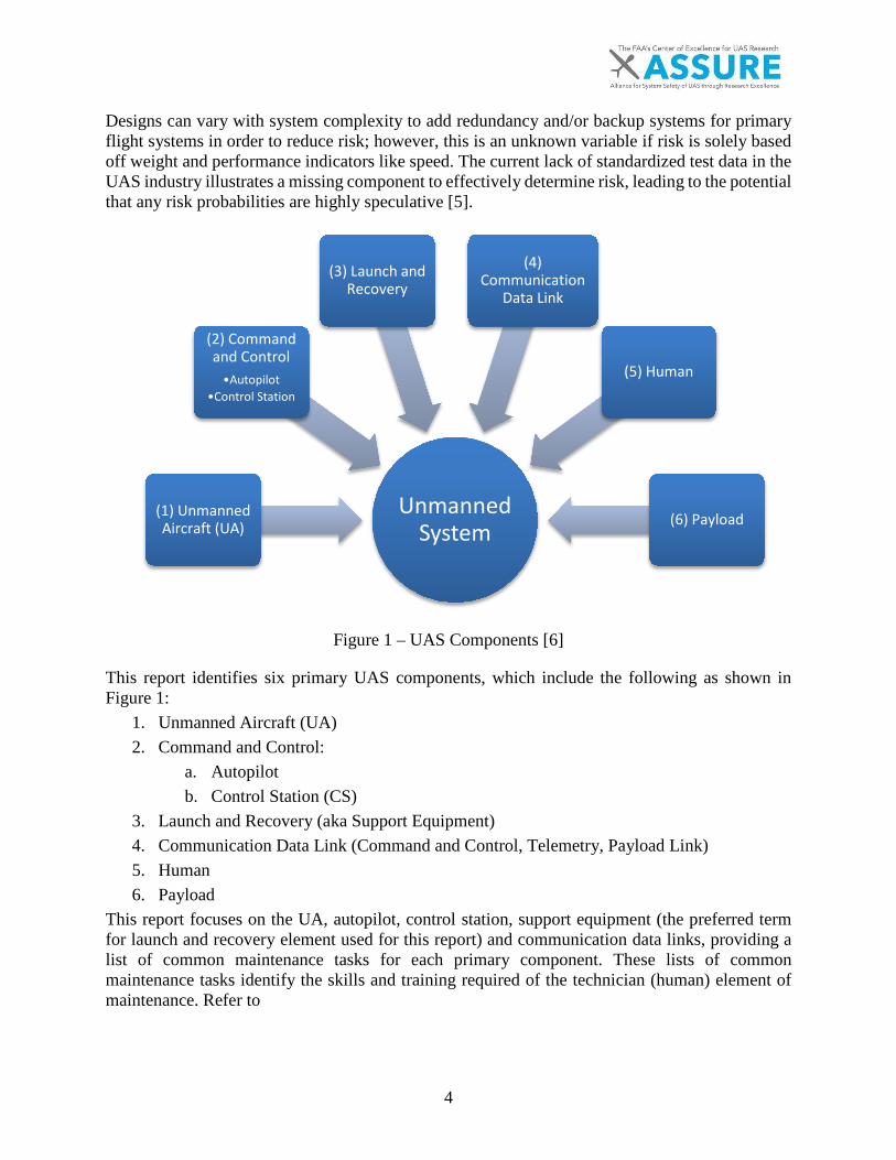
Designs can vary with system complexity to add redundancy and/or backup systems for primary flight systems in order to reduce risk; however, this is an unknown variable if risk is solely based off weight and performance indicators like speed. The current lack of standardized test data in the UAS industry illustrates a missing component to effectively determine risk, leading to the potential that any risk probabilities are highly speculative [5].
Figure 1 – UAS Components [6]
This report identifies six primary UAS components, which include the following as shown in Figure 1:
1. Unmanned Aircraft (UA)2. Command and Control:
a. Autopilotb. Control Station (CS)
3. Launch and Recovery (aka Support Equipment)4. Communication Data Link (Command and Control, Telemetry, Payload Link)5. Human6. Payload
This report focuses on the UA, autopilot, control station, support equipment (the preferred term for launch and recovery element used for this report) and communication data links, providing a list of common maintenance tasks for each primary component. These lists of common maintenance tasks identify the skills and training required of the technician (human) element of maintenance. Refer to
Unmanned System
(1) UnmannedAircraft (UA)
(2) Commandand Control
•Autopilot•Control Station
(3) Launch andRecovery
(4) Communication
Data Link
(5) Human
(6) Payload
5
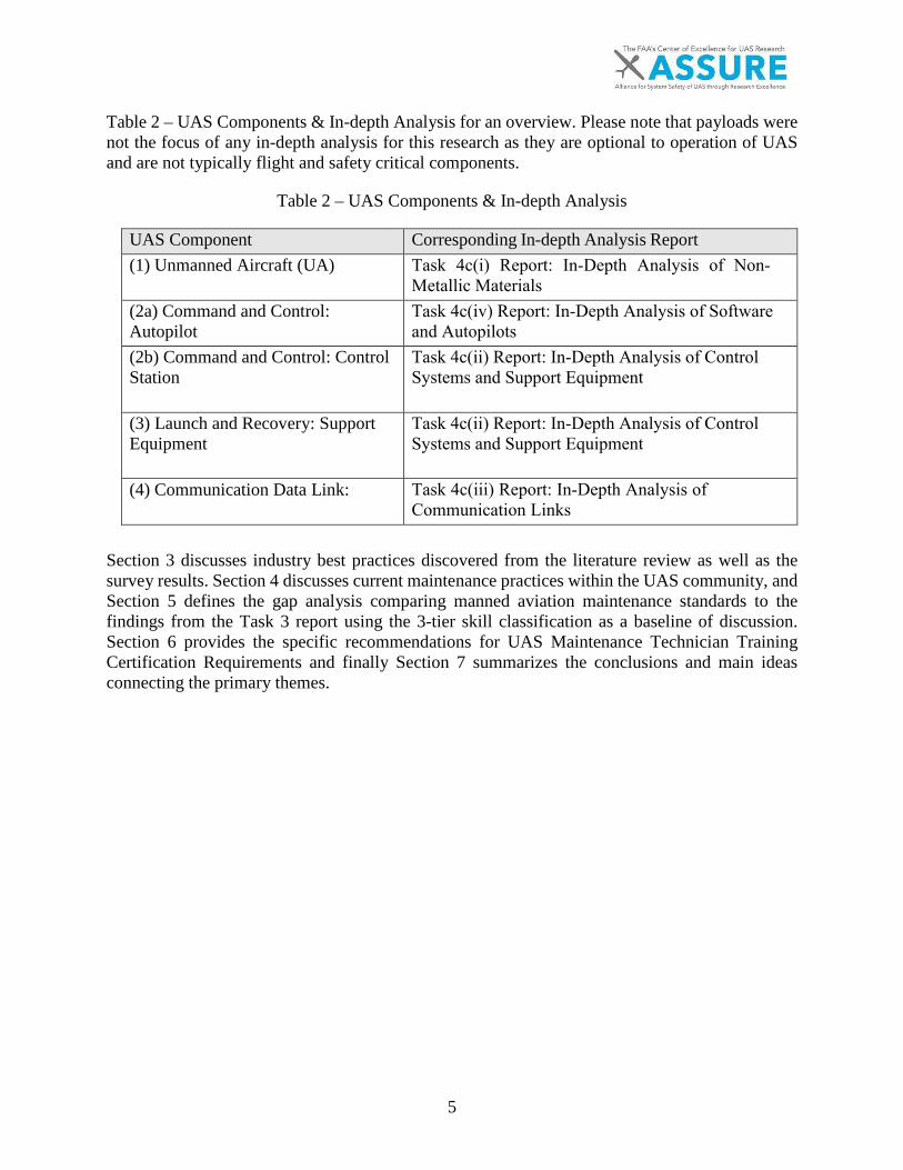
Table 2 – UAS Components & In-depth Analysis for an overview. Please note that payloads were not the focus of any in-depth analysis for this research as they are optional to operation of UAS and are not typically flight and safety critical components.
Table 2 – UAS Components & In-depth Analysis
UAS Component Corresponding In-depth Analysis Report (1) Unmanned Aircraft (UA) Task 4c(i) Report: In-Depth Analysis of Non-
Metallic Materials (2a) Command and Control: Autopilot
Task 4c(iv) Report: In-Depth Analysis of Software and Autopilots
(2b) Command and Control: Control Station
Task 4c(ii) Report: In-Depth Analysis of Control Systems and Support Equipment
(3) Launch and Recovery: SupportEquipment
Task 4c(ii) Report: In-Depth Analysis of Control Systems and Support Equipment
(4) Communication Data Link: Task 4c(iii) Report: In-Depth Analysis of Communication Links
Section 3 discusses industry best practices discovered from the literature review as well as the survey results. Section 4 discusses current maintenance practices within the UAS community, and Section 5 defines the gap analysis comparing manned aviation maintenance standards to the findings from the Task 3 report using the 3-tier skill classification as a baseline of discussion. Section 6 provides the specific recommendations for UAS Maintenance Technician Training Certification Requirements and finally Section 7 summarizes the conclusions and main ideas connecting the primary themes.
6
3. INDUSTRY BEST PRACTICES
The primary methods used to capture the UAS industry best practices were through administering a series of surveys and conducting a literature review of over 20 relevant documents. The combination of using first hand data retrieved from survey information, along with second hand data acquired from external authors, helped to establish a healthy baseline from prior knowledge while gaining insight from current users. Three surveys were given to a combined total of over 50 employees including organizations engaged in UAS maintenance, Original Equipment Manufacturers (OEM), as well as other organizations. Comprehensive database search methodologies that compile information from all published information sources (including government agency documentation) were used to evaluate the current state of the practice.
3.1 LITERATURE REVIEW
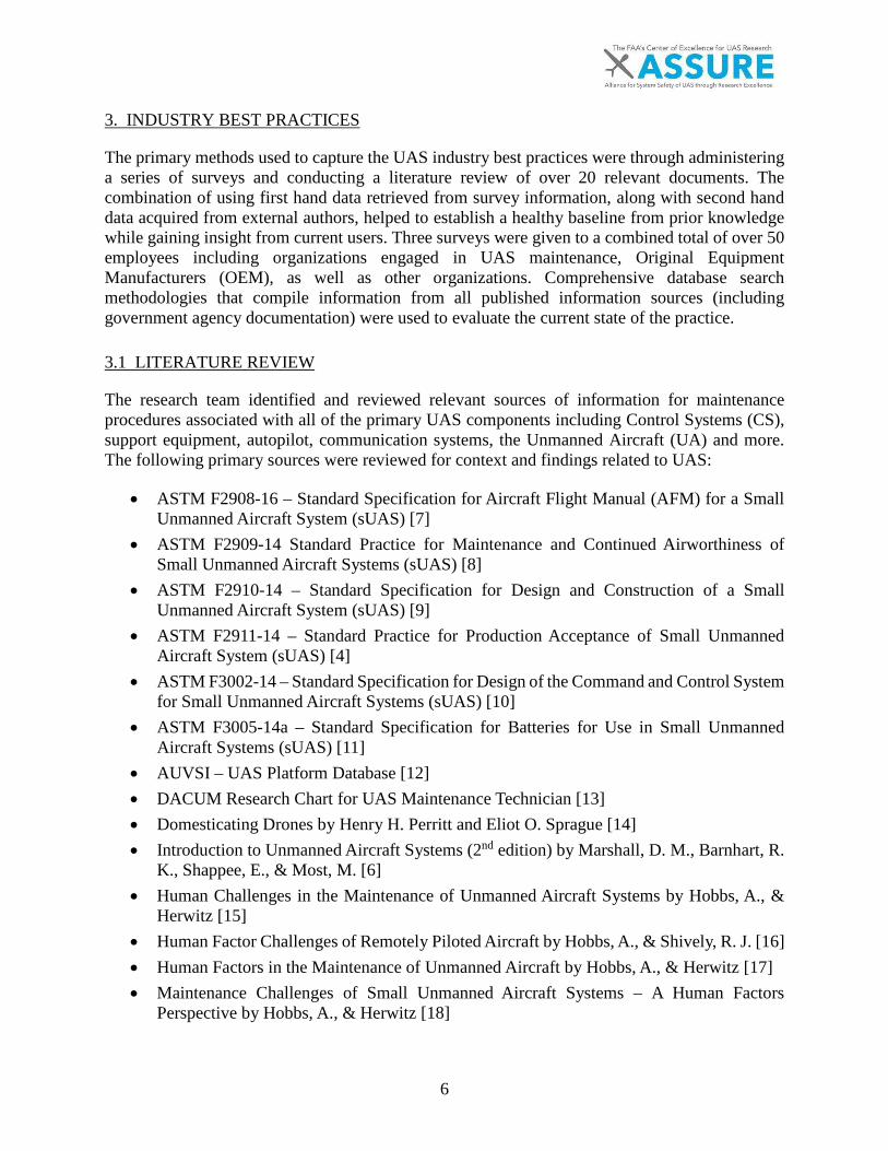
The research team identified and reviewed relevant sources of information for maintenance procedures associated with all of the primary UAS components including Control Systems (CS), support equipment, autopilot, communication systems, the Unmanned Aircraft (UA) and more. The following primary sources were reviewed for context and findings related to UAS:
• ASTM F2908-16 – Standard Specification for Aircraft Flight Manual (AFM) for a SmallUnmanned Aircraft System (sUAS) [7]
• ASTM F2909-14 Standard Practice for Maintenance and Continued Airworthiness ofSmall Unmanned Aircraft Systems (sUAS) [8]
• ASTM F2910-14 – Standard Specification for Design and Construction of a SmallUnmanned Aircraft System (sUAS) [9]
• ASTM F2911-14 – Standard Practice for Production Acceptance of Small UnmannedAircraft System (sUAS) [4]
• ASTM F3002-14 – Standard Specification for Design of the Command and Control Systemfor Small Unmanned Aircraft Systems (sUAS) [10]
• ASTM F3005-14a – Standard Specification for Batteries for Use in Small UnmannedAircraft Systems (sUAS) [11]
• AUVSI – UAS Platform Database [12]• DACUM Research Chart for UAS Maintenance Technician [13]• Domesticating Drones by Henry H. Perritt and Eliot O. Sprague [14]• Introduction to Unmanned Aircraft Systems (2nd edition) by Marshall, D. M., Barnhart, R.
K., Shappee, E., & Most, M. [6]• Human Challenges in the Maintenance of Unmanned Aircraft Systems by Hobbs, A., &
Herwitz [15]• Human Factor Challenges of Remotely Piloted Aircraft by Hobbs, A., & Shively, R. J. [16]• Human Factors in the Maintenance of Unmanned Aircraft by Hobbs, A., & Herwitz [17]• Maintenance Challenges of Small Unmanned Aircraft Systems – A Human Factors
Perspective by Hobbs, A., & Herwitz [18]
7
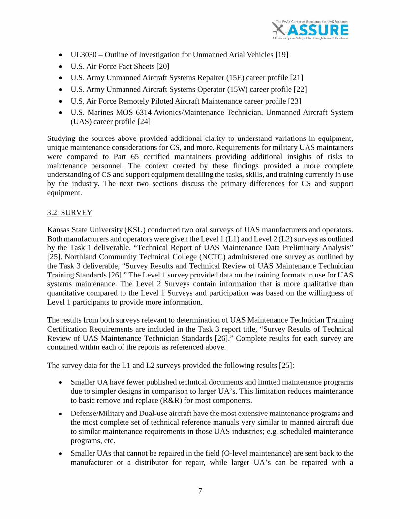
• UL3030 – Outline of Investigation for Unmanned Arial Vehicles [19] • U.S. Air Force Fact Sheets [20] • U.S. Army Unmanned Aircraft Systems Repairer (15E) career profile [21] • U.S. Army Unmanned Aircraft Systems Operator (15W) career profile [22] • U.S. Air Force Remotely Piloted Aircraft Maintenance career profile [23] • U.S. Marines MOS 6314 Avionics/Maintenance Technician, Unmanned Aircraft System
(UAS) career profile [24]
Studying the sources above provided additional clarity to understand variations in equipment, unique maintenance considerations for CS, and more. Requirements for military UAS maintainers were compared to Part 65 certified maintainers providing additional insights of risks to maintenance personnel. The context created by these findings provided a more complete understanding of CS and support equipment detailing the tasks, skills, and training currently in use by the industry. The next two sections discuss the primary differences for CS and support equipment. 3.2 SURVEY
Kansas State University (KSU) conducted two oral surveys of UAS manufacturers and operators. Both manufacturers and operators were given the Level 1 (L1) and Level 2 (L2) surveys as outlined by the Task 1 deliverable, “Technical Report of UAS Maintenance Data Preliminary Analysis” [25]. Northland Community Technical College (NCTC) administered one survey as outlined by the Task 3 deliverable, “Survey Results and Technical Review of UAS Maintenance Technician Training Standards [26].” The Level 1 survey provided data on the training formats in use for UAS systems maintenance. The Level 2 Surveys contain information that is more qualitative than quantitative compared to the Level 1 Surveys and participation was based on the willingness of Level 1 participants to provide more information. The results from both surveys relevant to determination of UAS Maintenance Technician Training Certification Requirements are included in the Task 3 report title, “Survey Results of Technical Review of UAS Maintenance Technician Standards [26].” Complete results for each survey are contained within each of the reports as referenced above. The survey data for the L1 and L2 surveys provided the following results [25]:
• Smaller UA have fewer published technical documents and limited maintenance programs due to simpler designs in comparison to larger UA’s. This limitation reduces maintenance to basic remove and replace (R&R) for most components.
• Defense/Military and Dual-use aircraft have the most extensive maintenance programs and the most complete set of technical reference manuals very similar to manned aircraft due to similar maintenance requirements in those UAS industries; e.g. scheduled maintenance programs, etc.
• Smaller UAs that cannot be repaired in the field (O-level maintenance) are sent back to the manufacturer or a distributor for repair, while larger UA’s can be repaired with a

8
combination of intermediate and depot level maintenance; OEM’s typically prefer to perform the repairs with respect to sUAS.
• The approach to the maintenance of larger and more complex aircraft (i.e. legacy military platforms) is more standardized and includes scheduled maintenance and inspection intervals similar to manned aircraft. The associated technical reference data details much of the required maintenance actions to be performed by the operator in the field.
• Smaller UA service support is typically available by phone with the OEM, while larger UA service support is provided by an OEM Field Service Representative (FSR). FSRs exist to support military operators on location allowing operators to keep aircraft in the field longer thereby reducing the logistical burden associated with replacement.
• Smaller UAS OEMs typically utilize social media and other online resources to communicate new information and techniques with their customers. They also gather feedback through these means to continuously improve their products.
The survey administered by NCTC revealed many current challenges to the effective training of UAS maintenance technicians [26]. The most significant challenge identified was a need for qualified personnel. Airframe and Powerplant (AIRCRAFT) certificated maintenance technicians are the most logical choice to locate skill class 3 (SC3) maintenance personnel. They must however still receive system specific and general avionics familiarization training in order to perform UAS maintenance with a degree of proficiency. As an aside, the available pool of qualified avionics personnel poses a more significant challenge for the industry. One organization identified a need to hire 109 avionics personnel to meet requirements for calendar year 2017 alone.

9
4. CURRENT MAINTENANCE PRACTICES
Current UAS maintenance operations and training apply three primary standards for the training of UAS maintenance personnel:
(1) ASTM F2909-14 Standard Practice for Maintenance and Continued Airworthiness of Small Unmanned Aircraft Systems (sUAS) [8], (2) The National Center for Aerospace and Transportation Technologies’ (NCATT) Standard Unmanned Aerial Systems Maintenance Technician Certification [27], and (3) The DACUM Research Chart for UAS Maintenance Technicians [13].
The ASTM F2909-14 standard provides a detailed list of tasks that can be performed for typical preflight inspections, periodic inspections, rules for repairs and alterations, as well as best practices for maintaining maintenance records [8]. The NCATT UAS Maintenance Technician Certification defines a broad and general skill set for all UAS. Scaling the requirements within the NCATT UAS Maintenance Technician Certification may improve the standard because the differences between maintenance skills required for small UAS maintenance vary drastically from those required for larger UAS [27]. The DACUM document provides a bullet point list of general knowledge and skills, future trends and concerns, worker behaviors, acronyms, related certifications, tools, equipment, supplies and materials. The DACUM also lists UAS tasks for 12 separate duties including the following:
A. Comply with UAS Health and Safety Protocols B. Comply with Foreign Object Elimination (FOE, aka Foreign Object Debris (FOD))
Policies and Procedures C. Comply with UAS Maintenance Documentation D. Perform UAS GCS Maintenance E. Maintain UAS Datalinks F. Perform UA Maintenance G. Manage UAS Ground Support Equipment (GSE, aka support equipment) H. Execute UA Flight Operations I. Manage UAS Parts J. Perform UAS Administrative Functions
Written surveys completed by UAS maintenance technicians and hiring managers provided the following industry challenges:
(1) A need for an exclusive electronics and avionics focused program separate from a manned aircraft maintenance program (2) A lack of basic networking knowledge, computer maintenance skills and associated troubleshooting procedures (3) A lack of qualified avionics technicians (4) A lack of formal maintenance training programs from manufacturers
10
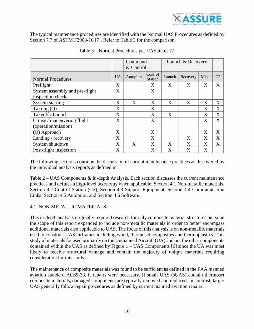
The typical maintenance procedures are identified with the Normal UAS Procedures as defined by Section 7.7 of ASTM F2908-16 [7]. Refer to Table 3 for the comparison.
Table 3 – Normal Procedures per UAS items [7]
Command & Control
Launch & Recovery
Normal Procedures UA Autopilot Control Station Launch Recovery Misc. C2
Preflight X X X X X X System assembly and pre-flight inspection check
X X
System starting X X X X X X X Taxiing (O) X X X X Takeoff / Launch X X X X X Cruise / maneuvering flight (operation/mission)
X X X X
(O) Approach X X X X Landing / recovery X X X X X System shutdown X X X X X X X Post-flight inspection X X X X X
The following sections continue the discussion of current maintenance practices as discovered by the individual analysis reports as defined in
Table 2 – UAS Components & In-depth Analysis. Each section discusses the current maintenance practices and defines a high-level taxonomy when applicable: Section 4.1 Non-metallic materials, Section 4.2 Control Station (CS), Section 4.3 Support Equipment, Section 4.4 Communication Links, Section 4.5 Autopilot, and Section 4.6 Software.
4.1 NON-METALLIC MATERIALS
This in-depth analysis originally required research for only composite material structures but soon the scope of this report expanded to include non-metallic materials in order to better encompass additional materials also applicable to UAS. The focus of this analysis is on non-metallic materials used to construct UAS airframes including wood, thermoset composites and thermoplastics. This study of materials focused primarily on the Unmanned Aircraft (UA) and not the other components contained within the UAS as defined by Figure 1 – UAS Components [6] since the UA was most likely to receive structural damage and contain the majority of unique materials requiring consideration for this study.
The maintenance of composite materials was found to be sufficient as defined in the FAA manned aviation standard AC65-33, if repairs were necessary. If small UAS (sUAS) contain thermoset composite materials, damaged components are typically removed and replaced. In contrast, larger UAS generally follow repair procedures as defined by current manned aviation repairs.

11
Other materials researched include thermoplastics, or foam, wood, and fabric. Thermoplastics are repairable through existing methods such as fusion and resistance welding, but those techniques are not recommended. Therefore, it is common to remove and replace damaged components for all UAS. Foam, wood and fabric materials did not receive an extensive study in this report. Expanded Polyolefin (EPO) foam is common in small UA (sUA), comprising the entire structure of the UA or often encasing the structure for a weight advantage. The EPO foam is often wrapped in either thermoset or thermoplastics on leading edge surfaces to inhibit damage while maintaining the structural form. Refer to "Task 4c(i) Report: In-Depth Analysis of Non-Metallic Materials" for more information.
Typical UA materials include: • Thermoset (composites)• Thermoplastics• Expanded Polyolefin (EPO) foam• Wood• Fabric• Aluminum – not included in this study• Combinations of materials (e.g. EPO wrapped in either thermoset or thermoplastics)
4.2 CONTROL SYSTEMS (CS)
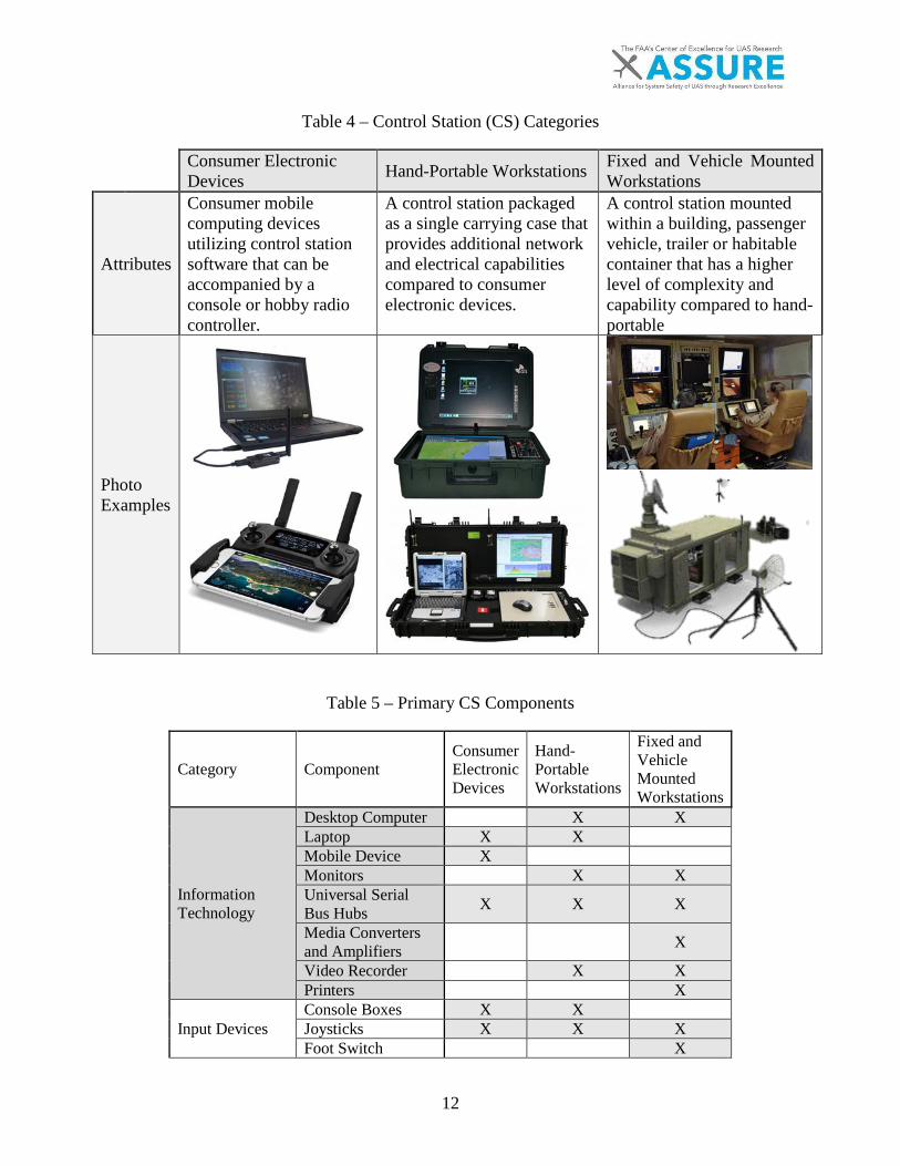
Control systems (CS) can be defined by their respective components and operational uses as listed in Table 4. Consumer electronic devices were found to have the smallest variety of components as they contain a single computing device and method for that device to communicate with the aircraft. Unmanned aircraft weighing less than 55 lbs. often employ this this type of CS, and operate within visual line of sight.
Hand-portable workstations are an intermediate category, with additional networking and information technology and a casing containing components. Unmanned aircraft (UA) weighing less than 55 lbs. and UAs that weigh more than 55 lbs. but operate within radio line of sight, utilize this type of CS. Fixed and passenger vehicle mounted workstations have the widest variety of components and are often used with large and complex UAs. Aircraft operated within radio line of sight and aircraft operating over the horizon utilize this type of CS. Refer to Table 5 for a list of primary CS components identified by category and component.
12
Table 4 – Control Station (CS) Categories
Consumer Electronic Devices Hand-Portable Workstations Fixed and Vehicle Mounted
Workstations
Attributes
Consumer mobile computing devices utilizing control station software that can be accompanied by a console or hobby radio controller.
A control station packaged as a single carrying case that provides additional network and electrical capabilities compared to consumer electronic devices.
A control station mounted within a building, passenger vehicle, trailer or habitable container that has a higher level of complexity and capability compared to hand-portable
Photo Examples
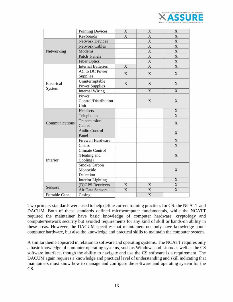
Table 5 – Primary CS Components
Category Component Consumer Electronic Devices
Hand-Portable Workstations
Fixed and Vehicle Mounted Workstations
Information Technology
Desktop Computer X X Laptop X X Mobile Device X Monitors X X Universal Serial Bus Hubs X X X
Media Converters and Amplifiers X
Video Recorder X X Printers X
Input Devices Console Boxes X X Joysticks X X X Foot Switch X
13
Pointing Devices X X X Keyboards X X X
Networking
Network Devices X X Network Cables X X Modems X X Patch Panels X X Fiber Optics X X
Electrical System
Internal Batteries X X X AC to DC Power Supplies X X X
Uninterruptable Power Supplies X X X
Internal Wiring X X Power Control/Distribution Unit
X X
Communications
Headsets X Telephones X Transmission Cables
X
Audio Control Panel
X
Interior
Firewall Hardware X Chairs X Climate Control (Heating and Cooling)
X
Smoke/Carbon Monoxide Detection
X
Interior Lighting X
Sensors (D)GPS Receivers X X X Air Data Sensors X X X
Portable Case Casing X Two primary standards were used to help define current training practices for CS: the NCATT and DACUM. Both of these standards defined microcomputer fundamentals, while the NCATT required the maintainer have basic knowledge of computer hardware, cryptology and computer/network security but avoided requirements for any kind of skill or hands-on ability in these areas. However, the DACUM specifies that maintainers not only have knowledge about computer hardware, but also the knowledge and practical skills to maintain the computer system. A similar theme appeared in relation to software and operating systems. The NCATT requires only a basic knowledge of computer operating systems, such as Windows and Linux as well as the CS software interface, though the ability to navigate and use the CS software is a requirement. The DACUM again requires a knowledge and practical level of understanding and skill indicating that maintainers must know how to manage and configure the software and operating system for the CS.
14
Both the NCATT and DACUM also emphasize knowledge and skill in computer networks and their respective hardware and software. The NCATT requires a basic knowledge of network devices such as routers and modems, the layout, and configuration of networks and network addressing. The DACUM covers a smaller variety of networking hardware compared to the NCATT as only routers and wireless devices are covered. This indicates that the knowledge and ability to adjust network addresses and configuration are valuable to a CS maintainer. The DACUM however, does not indicate that a maintainer needs to be able to troubleshoot computer networks, while the NCATT indicates a basic ability to troubleshoot is required.
The NCATT’s primary training considerations relate to the electrical system. The DACUM also covers electrical systems however; electrical systems for the aircraft and engine are specified though many of the same concepts and tasks may apply. The NCATT requires a UAS maintainer have a basic knowledge and understanding of the name and function of electrical components such as resistors, transformers, power supply circuits for alternating and direct current systems. Other basic electricity knowledge such as how circuits function, calculation of electrical values from circuits, reading wiring diagrams and other considerations for wiring/connectors are also required.
A handful of knowledge areas required by the NCATT relate to maintenance of CS computers. The NCATT requires knowledge of shielding, cooling systems, how to handle electrostatic sensitive devices and circuit protection; knowledge a maintainer could use to protect computers and other devices in the CS. A maintainer is also required to be able to troubleshoot, inspect, and repair circuits, electrical components and wiring as well as be able to take measurements using equipment such as voltmeters and oscilloscopes. These types of tasks are oriented to intermediate level maintenance (I-level), which is more typical for the SC2 and SC3 skill levels.
Similar to the maintainers of manned aircraft, a basic knowledge of how to operate and check the functionality of CS workstations, power systems, video equipment and software is required for UAS maintainers according to NCATT. This level of knowledge supports the maintainer when conducting pre, post, and scheduled inspections for the CS and when taking corrective measures such as workstation resets, the usage of data logs and when updating software.
The NCATT and DACUM were not the only sources of information related to CS maintenance skills and knowledge. A maintenance task list was created using data from procedural and repair tasks through the Certificate of Authorization (CoA)/Section 333 incident and accident reports provided by the FAA [28]. The NCATT UAS Maintenance Standard [27], the DACUM Research Chart for UAS Maintenance Technician [13], the Maintenance and Repair Database (See: A5 Task 2), the United States Air Force Accident Reports related to UAS [29], and a list of tasks for a complex CS, shared by Northland Community and Technical College (NCTC) (the Modified Shelter Tech Task List [30]), were also used. The incident and accident reports allowed for the discovery of necessary repair tasks, while all other sources determined both repair and procedural maintenance tasks. To view the entire task list and the sources of each specific task, refer to Appendix A.
Some of the skills identified related to computers and networks, similar to the NCATT and DACUM. Tasks indicated that a maintainer would need to know how to: remove and replace

15
peripherals such as input devices and printers, clean and inspect fiber optics and preserve/backup data on computers and other CS equipment.
Skills related to maintenance of the CS were also discovered through investigation of the maintenance task list such as how to prepare the CS for safe maintenance, removing and replacing shelter interior features such as chairs and lights (in larger UAS systems) and the proper methods for safely cleaning the CS and any built-in-test (BIT) features the CS may include.
Finally, tasks were defined for voice communication systems, which include updating system software, removing, replacing, and configuring components of the system, as well as checking for proper function.
4.3 SUPPORT EQUIPMENT
This process identified skills and knowledge requirements for support equipment using the same approach as defined in Section 4.2 However, there is much less information available for this equipment. This is due to the limited amount of source data containing support equipment maintenance tasks as well as fewer skills and knowledge areas identified in the NCATT and DACUM. A total of 18 separate skill and knowledge areas were identified with the primary focus of these skills being launch and recovery systems as well as miscellaneous equipment including electrical generators and engine-related support equipment.
The NCATT and the DACUM both indicate maintainers require knowledge of electrical generators; however, the NCATT requires a more basic level of knowledge in comparison. The DACUM defines that maintainers need to be able to conduct maintenance tasks on several parts of a reciprocating engine including:
• Engine cooling systems• Engine electrical systems• Engine exhaust and reverser systems• Engine fuel systems• Engine inspection• Engine instrument systems• Fuel metering systems• Ignition and starting systems• Induction and engine airflow systems• Lubrication systems
While being able to maintain a reciprocating engine may not be specific to an electrical generator, a diesel or gasoline fueled engine drives the generator, and therefore the same concepts apply to those types of generators.
A maintainer is also required to understand manual and autonomous launch and recovery systems per the NCATT standard. The ability to work on fluid lines, fittings and hydraulic and pneumatic power systems is also needed to maintain launchers per the DACUM rather than just knowledge of the system in general. No other skill and knowledge areas were identified; however, more skill

16
is likely to be required in order to maintain other varieties of support equipment. Refer to Table 6 for Types of Launch Equipment,

17
Table 7 for Types of Recovery Equipment, and Table 8 for Types of Miscellaneous Equipment.
Table 6 – Types of Launch Equipment
Launch Equipment Type Description
Hand Launch This method requires the personnel to throw the UA.
Pneumatic Catapult Compressed air or gas propels the aircraft on a rail-mounted cart until the cart reaches the end of the rail where the aircraft is thrown into the air.
Hydraulic Catapult Pressurized liquid charges a pneumatic accumulator and propel the aircraft on a rail-mounted cart until the cart reaches the end of the rail where the aircraft is thrown into the air.
Spring-loaded Catapult The restoring force of an extended or compressed spring propels the aircraft on a rail-mounted cart until the cart reaches the end of the rail where the aircraft is thrown into the air.
Bungee Launcher The restoring force of an elastic band propels the aircraft forward on a rail or in the air.
Trebuchet A fulcrum with the aircraft on one end and a heavy object on the other. The object drops, causing the fulcrum to swing and throw the aircraft into the air.
Car-top Launcher The aircraft sits in a cradle atop a passenger vehicle. The passenger vehicle accelerates until the aircraft reaches a suitable airspeed and rotates up and away from the passenger vehicle.
Takeoff Cart The aircraft sits atop a cart with wheels. Using its own thrust, the aircraft propels itself forward on the cart until it reaches a suitable speed and rotates up and away from the cart.

18
Table 7 – Types of Recovery Equipment
Equipment Type Description
Airborne Capture: Net
A net to capture the aircraft in flight.
Airborne Capture: Hanging Cable
A hanging cable that the aircraft flies in to and then hooked to the cable, which brings the aircraft to a halt mid-air.
Arresting Gear A horizontal cable laying on a runway that snags and then slows down the aircraft upon touchdown.
Parachutes A canopy that is deployed overhead the aircraft to allow it to float at a safe speed to the ground.
Airbags A self-inflating cushion used to dampen a parachute landing.
Table 8 – Types of Miscellaneous Equipment
Type Equipment type Description
Engine Support Equipment (e.g. turbine, gas, etc.)
Fuel & Defuel device -Powered pump -Hand crank pump
Devices used to add or remove fuel from an aircraft’s tanks.
Fuel storage device -Cart
An external tank often used in conjunction with a fueling device to transfer fuel to the UA’s tanks.
Starting Device -Electric Pump -Compressed Air
An external device used to turn a reciprocating or turbine engine in order to start the engine.
External Power Generator -Diesel or gas powered
A reciprocating engine that turns an electric motor or alternator to produce electricity.
Ground Power Unit (GPU) An off board battery often called a power cart that provides power to the CS or UA on the ground.
Active Sensors Ground Based Radar A system for detecting and tracking aircraft by use of pulsing electromagnetic waves.
Passive Equipment Targets A symbol, pattern or position reporting device on the ground that the UA can use to track the location of an object or itself.
4.4 COMMUNICATION LINKS
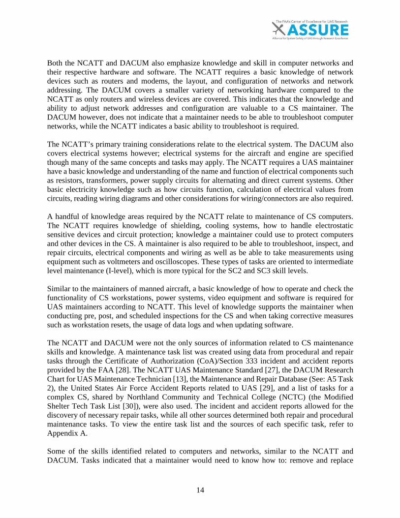
UAS utilize a variety of communication links. The most common links included in this report are Uplink command and control (including C2), downlink telemetry, voice communications (primarily used for contact with ATC and general awareness in the field), and the payload link. Refer to Table 9 for a basic description for each of the Communication Link elements.
19
Table 9 – Communication Link Elements
Type Description Photo Example Uplink Command and Control
Transfers operator inputs and commands from the ground to the UA.
Downlink Telemetry Transfers flight data and aircraft status to the ground.
Voice Communications
Allows the operator to transmit and receive vocal communications between the control station and air traffic control or other aircraft operations. In some cases, the aircraft acts as a relay between the CS and air traffic control.
Payload Link Transfers data gather by the UA’s payload to the ground.
ASTM F3002-14a “Design of the Command and Control System for Small Unmanned Aircraft Systems (sUAS)” [10] defines four primary types of communication links: C2 for command and control, Telemetry, and two possible payload links using a reversed double transmit and receive system.

20
Figure 2 – High-Level Functional Block Diagram of the C2 System [10]
Similar to Section 4.2, a list of skills and knowledge related to maintenance for communication links was created using the NCATT Unmanned Aircraft System (UAS) Maintenance Standard, the DACUM Research Chart for UAS Maintenance Technicians and a variety of other sources. Refer to " Task 4c(iii) Report: In-Depth Analysis of Communication Links" for the complete list of sources used.
DESCRIPTION: • On the Ground Station side, the Display function may be separate from the HMI control input function or
contained within the HMI control input function.
• On the UAS side, the light green box represents where the flight management, lost link function and timer,
fly away protection function, potential navigation input (GPS) and the C2 RX and TX may reside. All of these
functions could reside in one physical device or multiple devices.
• RF links are depicted as individual link pairs-they may be in one radio or multiple radios, depending on
regulatory requirements.
• The lost link function is depicted to be triggered prior to a fly away function

21
The NCATT requires that maintainers be knowledgeable in radio theory and frequency bands. This includes an understanding of the various frequency bands and the federal regulations governing those bands. Understanding basic radio components such as oscillators, filters, amplifiers, tuning circuits, modulators and demodulators is also a requirement. NCATT requires knowledge and skills related to antennas and transmission lines. Maintainers must understand the various cables/connector types that exist for communication link antennas as well as knowledge of installation practices for antennas, antenna tuning and system troubleshooting. NCATT further requires maintainers understand various types of transmission wiring, which feed to and from antennas, as well as how to install, maintain and fabricate them. An understanding of impedance, corrosion control, velocity factors, and voltage standing wave ratio were indicated as well. Consistent with the UA and CS, the skills and knowledge for the electrical systems are applicable to communication systems as well. The DACUM also covers electrical systems; however, UA and engine electrical systems are specified separately, though many of the same concepts and tasks apply as described above. The NCATT requires that a UAS maintainer have a basic knowledge and understanding of the name and function of electrical components including resistors, transformers, power supply circuits and more for both alternating and direct current systems. Other basic electricity knowledge, such as how circuits function, calculation of electrical values from circuits, reading wiring diagrams and considerations for wiring and connectors, are also required. A few miscellaneous electrical skills were also present in the NCATT requirements including knowledge of electrical component heating, cooling, and handling of electrostatic sensitive devices. A maintainer is also required to be able to troubleshoot, inspect and repair electrical circuits/components and wiring as well as take measurements using equipment such as voltmeters and oscilloscopes. Refer to Figure 3 for a list of the primary communication link components.
Figure 3 – Primary Communication Link Components
All Links TransmittersReceiversOmnidirectional AntennasTransceiversTransmission LinesRadio FiltersAmplifiersDirectiona; AntennasAntenna Trackers (points antenna at targeted device)Parabolic Dish Antennas
Communication Link Components
More Complex and Longer Range Links
22
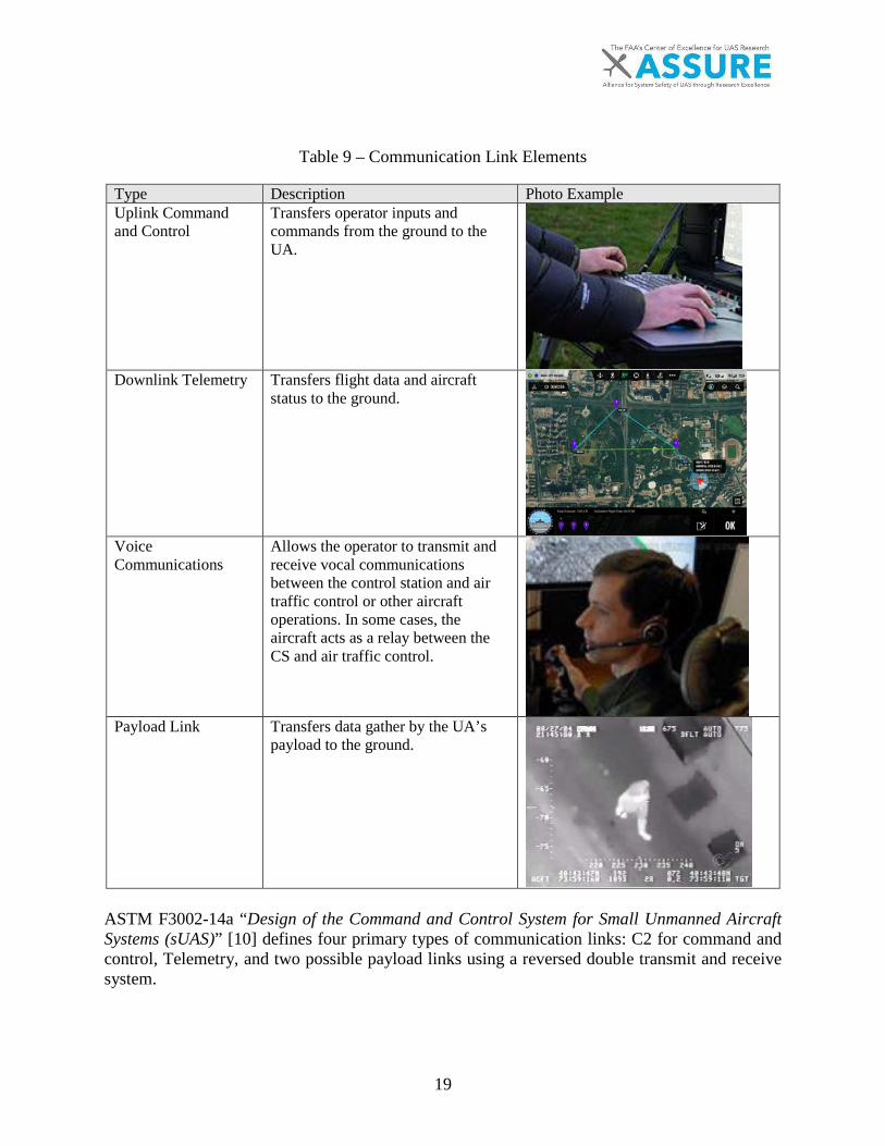
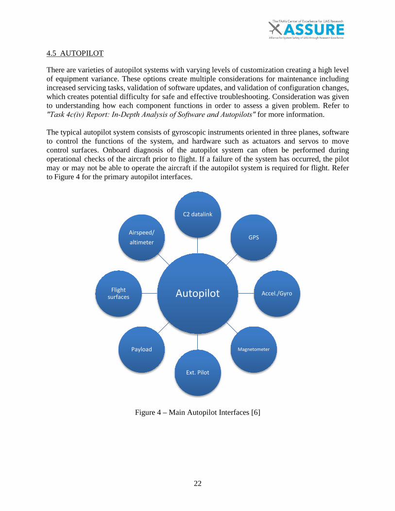
4.5 AUTOPILOT
There are varieties of autopilot systems with varying levels of customization creating a high level of equipment variance. These options create multiple considerations for maintenance including increased servicing tasks, validation of software updates, and validation of configuration changes, which creates potential difficulty for safe and effective troubleshooting. Consideration was given to understanding how each component functions in order to assess a given problem. Refer to "Task 4c(iv) Report: In-Depth Analysis of Software and Autopilots" for more information.
The typical autopilot system consists of gyroscopic instruments oriented in three planes, software to control the functions of the system, and hardware such as actuators and servos to move control surfaces. Onboard diagnosis of the autopilot system can often be performed during operational checks of the aircraft prior to flight. If a failure of the system has occurred, the pilot may or may not be able to operate the aircraft if the autopilot system is required for flight. Refer to Figure 4 for the primary autopilot interfaces.
Figure 4 – Main Autopilot Interfaces [6]
Autopilot
C2 datalink
GPS
Accel./Gyro
Magnetometer
Ext. Pilot
Payload
Flight surfaces
Airspeed/altimeter
23
UAS operations can reveal autopilot related issues during flight, but pre-flight inspections can help avoid these potential problems beforehand. Examples of in-flight autopilot malfunctions in UAS include loss of control of the aircraft, unreliable telemetry data to the user, and the inability to operate the aircraft manually by remote control links. Performing effective functional checks of autopilots are sometimes limited by accessibility to proper hardware/software. The combination of software tools onboard most systems provides the functionality to diagnose and further prevent the user from operating the aircraft without positive communication transfer between all elements of the system.
4.6 SOFTWARE
The research approach to identifying software maintenance considerations shows similarities to those defined in Section 4.2. The primary software items include operating systems such as Windows and Linux as well as the CS software interface, applications, computer networking, autopilot, and payload related software. Payload related software was not studied as a primary consideration for this report since it is often used only to collect data and occasionally for situation awareness. Refer to "Task 4c(iv) Report: In-Depth Analysis of Software and Autopilots" for more information.
The DACUM and NCATT documents contained the most specific information for software available. The DACUM requires a knowledge and practical level of understanding and skill indicating that maintainers must know how to manage and configure the software and operating system for the CS. Both the NCATT and DACUM emphasize knowledge and skill in computer networks and their respective hardware and software. The NCATT requires a basic knowledge of network devices such as routers and modems, system layout, configuration of networks and network addressing while the DACUM covers a smaller variety of networking hardware compared to the NCATT including only routers and wireless devices. The NCATT indicates that the knowledge and the ability to troubleshoot computer networks, adjust network addresses and configuration are valuable to a CS maintainer. Overall, the NCATT requires more network related skills and knowledge than the DACUM.
Autopilot manufacturers and engineers continuously develop and release software and firmware updates on a regular basis. The update time lines can range from once every two years (Piccolo) to once every two to three months (DJI). The updates include improvements in reliability of the software, new features, and operational uses of the autopilot. Many times an update will address a specific safety of flight issue.
The popular DJI products will not allow the user to perform the flight until the unit has completed the update. Other products such as Piccolo and Mission Planner remove responsibility from the manufacturer and place the responsibility of software updates on the user. This condition potentially leads to software updates required for the safety of flight that are not being completed, further allowing users to operate with outdated or unstable software.
24
5. THE GAP ANALYSIS
The Task 4b gap analysis is the first step in developing maintenance technician training certification requirements for unmanned aircraft systems (UAS). Manned standards were benchmarked per the scope of work in order to assess the applicability of current manned maintenance standards to unmanned aircraft systems maintenance tasks. This report will discuss the applicability of three standards from the Federal Aviation Administration (FAA) and one standard from the European Aviation Safety Agency (EASA). These regulations directly related to the performance of the maintenance tasks or to defining basic maintainer requirements.
FAA 14 Code of Federal Regulations (CFR) Part 147 sets forth the requirements for aviation maintenance technician schools to include curriculum requirements [31]. The required subject matter is listed in Appendices B, C and D for General, Airframe and Powerplant, respectively. The curriculum for each of the ratings must specify at a minimum, the subject matter, as well as the required skill performance level prescribed within its associated appendix.
FAA 14 CFR Part 65 dictates the certification of Airmen other than flight crewmembers. Specifically, we benchmarked Subpart D and Subpart E of this Part. Subpart D applies to maintenance technician certification while Subpart E applies to the Repairman certification [32]. The core difference between the two being portability. A maintenance technician has the required knowledge and training and is not geographically restricted within the United States (US) while a Repairman is restricted to a specific function at a specific location.
FAA 14 CFR Part 43 is a regulation that governs the continued airworthiness of a certificated aircraft by prescribing rules for maintenance, preventive maintenance, rebuilding, alteration, and repair of those aircraft [33]. Among other things, Part 43 describes what constitutes the different types of maintenance, who may perform the maintenance, and specifies the recordkeeping requirements related to that maintenance. Analyzing Part 43 was necessary to understand potential certification impacts for UAS in the future. Although it did not identify specific skills for maintainers, it was useful to better understand existing processes that are necessary to certify an airplane since maintenance is directly tied to certification to maintain continued airworthiness.
EASA Part-66 governs the certification requirements to meet European Aviation Maintenance License (AML) requirements [34]. This is the European equivalent to Advisory Circular 65-2D/ 14 CFR Part 147 Appendices B-D. EASA has 32 member states and a worldwide presence in five locations outside of their member states. According to the Advanced Notice of Proposed Amendment 2015-10, EASA is adopting a risk performance based approach to unmanned aircraft regulations by outlining three categories:
1. Open category (low risk): safety is ensured through operational limitations, compliancewith industry standards, requirements on certain functionalities, and a minimum set ofoperational rules. Enforcement shall be ensured by the police.
2. Specific operation category (medium risk): authorization by National AviationAuthorities (NAAs), possibly assisted by a Qualified Entity following a risk assessmentperformed by the operator. A manual of operations shall list the risk mitigation measures.
25
3. Certified category (higher risk): requirements comparable to manned aviationrequirements. Oversight by NAAs (issue of licenses and approval of maintenance,operations, training, Air Traffic Management (ATM)/Air Navigation Services (ANS) andaerodrome organizations) and by EASA (design and approval of foreign organizations).
Many of the EASA requirements align with the skill class 1, 2, and 3 classifications outlined in this gap analysis.
5.1 UAS MAINTENANCE SKILL CLASSES
In order to analyze and discuss the requirements for training UAS maintenance technicians that will span the entire spectrum, the authors of this report determined it necessary to divide these discussions into three major categories. Defining the differences in skillsets required for different aircraft based on equipage and complexity established the skill class categorization.
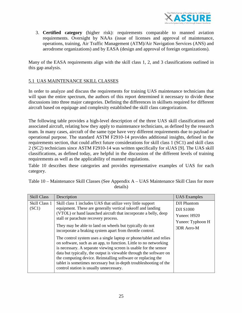
The following table provides a high-level description of the three UAS skill classifications and associated aircraft, relating how they apply to maintenance technicians, as defined by the research team. In many cases, aircraft of the same type have very different requirements due to payload or operational purpose. The standard ASTM F2910-14 provides additional insights, defined in the requirements section, that could affect future considerations for skill class 1 (SC1) and skill class 2 (SC2) technicians since ASTM F2910-14 was written specifically for sUAS [9]. The UAS skill classifications, as defined today, are helpful in the discussion of the different levels of training requirements as well as the applicability of manned regulations. Table 10 describes these categories and provides representative examples of UAS for each category.
Table 10 – Maintenance Skill Classes (See Appendix A – UAS Maintenance Skill Class for more details)
Skill Class Description UAS Examples Skill Class 1 (SC1)
Skill class 1 includes UAS that utilize very little support equipment. These are generally vertical takeoff and landing (VTOL) or hand launched aircraft that incorporate a belly, deep stall or parachute recovery process.
They may be able to land on wheels but typically do not incorporate a braking system apart from throttle control.
The control system uses a single laptop or phone/tablet and relies on software, such as an app, to function. Little to no networking is necessary. A separate viewing screen is usable for the sensor data but typically, the output is viewable through the software on the computing device. Reinstalling software or replacing the tablet is sometimes necessary but in-depth troubleshooting of the control station is usually unnecessary.
DJI Phantom DJI S1000 Yuneec H920 Yuneec Typhoon H 3DR Aero-M
26
Maintenance on these aircraft is nearly all electronic. Remove and Replace (R&R) of broken airframe or electronic devices is typical of this group.
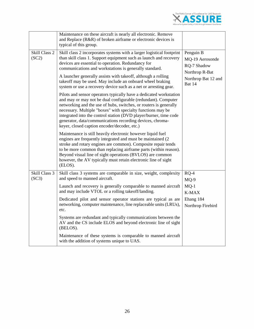
Skill Class 2 (SC2)
Skill class 2 incorporates systems with a larger logistical footprint than skill class 1. Support equipment such as launch and recovery devices are essential to operation. Redundancy for communications and workstations is generally standard.
A launcher generally assists with takeoff, although a rolling takeoff may be used. May include an onboard wheel braking system or use a recovery device such as a net or arresting gear.
Pilots and sensor operators typically have a dedicated workstation and may or may not be dual configurable (redundant). Computer networking and the use of hubs, switches, or routers is generally necessary. Multiple "boxes" with specialty functions may be integrated into the control station (DVD player/burner, time code generator, data/communications recording devices, chroma-keyer, closed caption encoder/decoder, etc.)
Maintenance is still heavily electronic however liquid fuel engines are frequently integrated and must be maintained (2 stroke and rotary engines are common). Composite repair tends to be more common than replacing airframe parts (within reason). Beyond visual line of sight operations (BVLOS) are common however, the AV typically must retain electronic line of sight (ELOS).
Penguin B MQ-19 Aerosonde RQ-7 Shadow Northrop R-Bat Northrop Bat 12 and Bat 14
Skill Class 3 (SC3)
Skill class 3 systems are comparable in size, weight, complexity and speed to manned aircraft.
Launch and recovery is generally comparable to manned aircraft and may include VTOL or a rolling takeoff/landing.
Dedicated pilot and sensor operator stations are typical as are networking, computer maintenance, line replaceable units (LRUs), etc.
Systems are redundant and typically communications between the AV and the CS include ELOS and beyond electronic line of sight (BELOS).
Maintenance of these systems is comparable to manned aircraft with the addition of systems unique to UAS.
RQ-4 MQ-9 MQ-1 K-MAX Ehang 184 Northrop Firebird
27
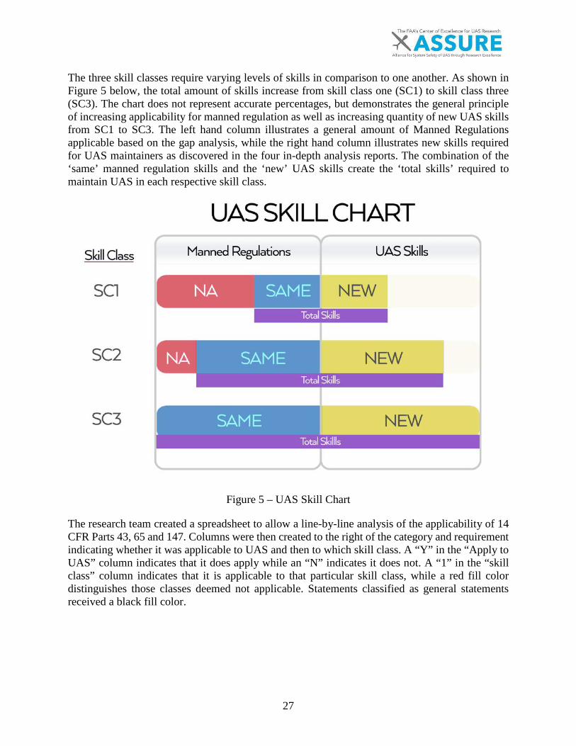
The three skill classes require varying levels of skills in comparison to one another. As shown in Figure 5 below, the total amount of skills increase from skill class one (SC1) to skill class three (SC3). The chart does not represent accurate percentages, but demonstrates the general principle of increasing applicability for manned regulation as well as increasing quantity of new UAS skills from SC1 to SC3. The left hand column illustrates a general amount of Manned Regulations applicable based on the gap analysis, while the right hand column illustrates new skills required for UAS maintainers as discovered in the four in-depth analysis reports. The combination of the ‘same’ manned regulation skills and the ‘new’ UAS skills create the ‘total skills’ required to maintain UAS in each respective skill class.
Figure 5 – UAS Skill Chart
The research team created a spreadsheet to allow a line-by-line analysis of the applicability of 14 CFR Parts 43, 65 and 147. Columns were then created to the right of the category and requirement indicating whether it was applicable to UAS and then to which skill class. A “Y” in the “Apply to UAS” column indicates that it does apply while an “N” indicates it does not. A “1” in the “skill class” column indicates that it is applicable to that particular skill class, while a red fill color distinguishes those classes deemed not applicable. Statements classified as general statements received a black fill color.

28
Representatives from Northland Community and Technical College (NCTC), Kansas State University (KSU) and Embry Riddle Aeronautical University (ERAU) participated in a line-by-line analysis of each spreadsheet. The team then met via teleconference in order to discuss any disagreements in analysis and come to a consensus. This consensus document is located in Appendices B-D. Table 11 shows an excerpt.
Table 11 – Excerpt from Part 147 Analysis
Category Requirement Apply to UAS? SC1 SC2 SC3
Scalable to
CONOPs
Basic Electricity
1. Calculate and measurecapacitance and inductance.
Y 1 1 1 N
2. Calculate and measureelectrical power.
Y 1 1 1 N
3. Measure voltage, current,resistance, and continuity.
Y 1 1 1 N
5.2 STANDARDS OVERVIEW
Task 3 introduced the National Center for Aerospace and Transportation Technologies’ Unmanned Aerial Systems Maintenance [27] certification, and the American Society for Testing and Materials [8] F2909-14 Standard Practice for Maintenance and Continued Airworthiness of SmallUnmanned Aircraft Systems (sUAS). Using these documents, prior research and extrapolatingtasks based on the equipment found within each skill category, the research team assessed theapplicability of the requirements within 14 CFR Parts 43, 65 and 147. The gap analysis conductedon EASA Part-66 also included referenced materials based on OEM requirements and aircraft typespecific training. The type specific requirements outlined in Part-66 serve as a catch all for allaircraft including unmanned aircraft systems.
5.2.1 14 CFR PART 43
The 14 CFR Part 43 prescribes the rules governing the maintenance, preventive maintenance, rebuilding, and alteration of aircraft and components of aircraft with a U.S. airworthiness certificate. Part 43 has 357 individual requirements partitioned into 20 categories. Some of these requirements were general requirements. Twenty-five general requirements have been filled with a black color (Refer to Appendix A), leaving 332 additional requirements. The color red identifies requirements that are not applicable. Requirements that reference any Part that was not modified or updated to include UAS considerations, or were not applicable to UAS without change, were not applicable for this research. § 43.17 Maintenance, preventive maintenance, and alterations performed on U.S. aeronautical products by certain Canadian persons is one example of a category that does not apply as written, but could be applicable as soon as an airworthiness standard is in place.
29
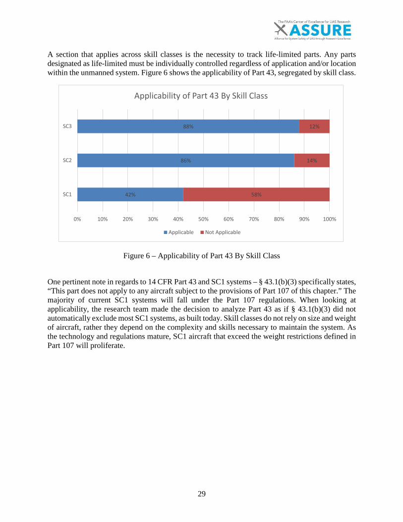
A section that applies across skill classes is the necessity to track life-limited parts. Any parts designated as life-limited must be individually controlled regardless of application and/or location within the unmanned system. Figure 6 shows the applicability of Part 43, segregated by skill class.
Figure 6 – Applicability of Part 43 By Skill Class
One pertinent note in regards to 14 CFR Part 43 and SC1 systems – § 43.1(b)(3) specifically states, “This part does not apply to any aircraft subject to the provisions of Part 107 of this chapter.” The majority of current SC1 systems will fall under the Part 107 regulations. When looking at applicability, the research team made the decision to analyze Part 43 as if § 43.1(b)(3) did not automatically exclude most SC1 systems, as built today. Skill classes do not rely on size and weight of aircraft, rather they depend on the complexity and skills necessary to maintain the system. As the technology and regulations mature, SC1 aircraft that exceed the weight restrictions defined in Part 107 will proliferate.
42%
86%
88%
58%
14%
12%
0% 10% 20% 30% 40% 50% 60% 70% 80% 90% 100%
SC1
SC2
SC3
Applicability of Part 43 By Skill Class
Applicable Not Applicable
30
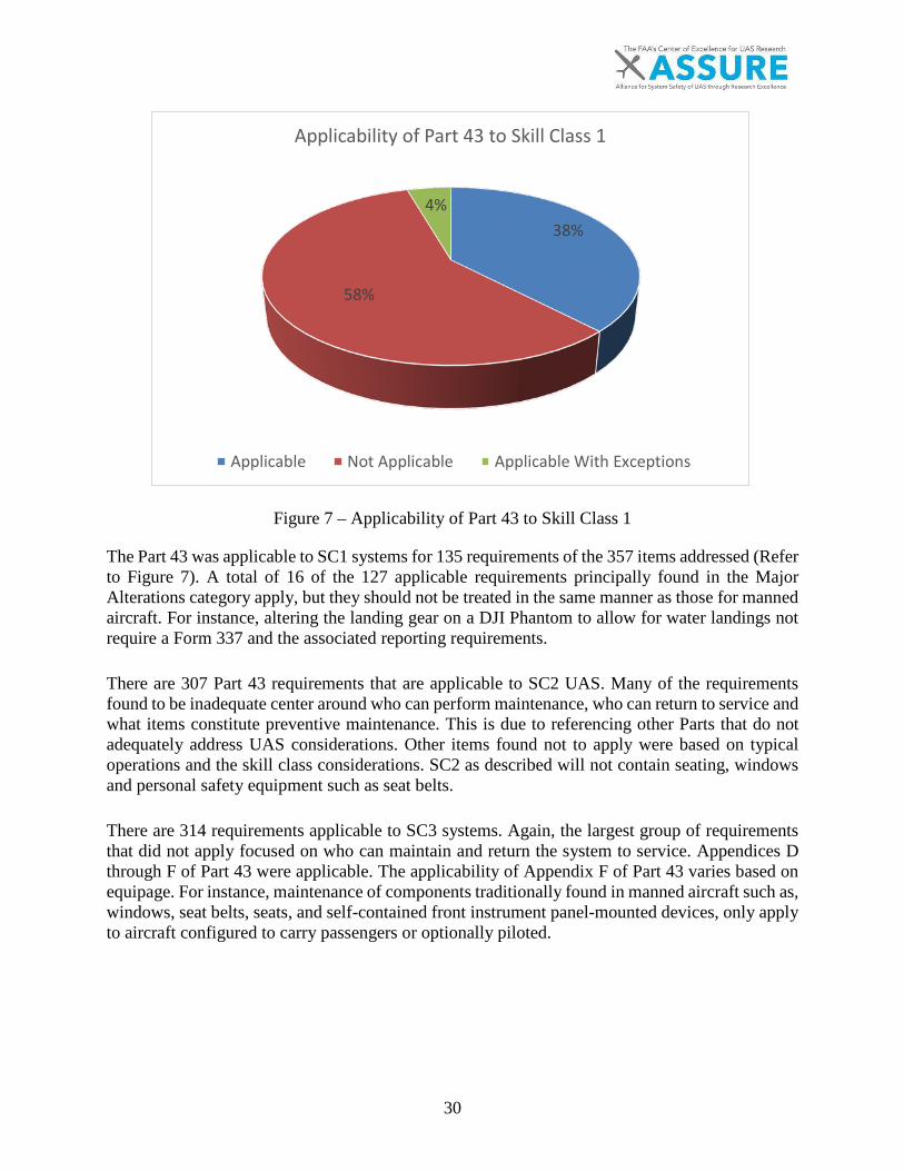
Figure 7 – Applicability of Part 43 to Skill Class 1
The Part 43 was applicable to SC1 systems for 135 requirements of the 357 items addressed (Refer to Figure 7). A total of 16 of the 127 applicable requirements principally found in the Major Alterations category apply, but they should not be treated in the same manner as those for manned aircraft. For instance, altering the landing gear on a DJI Phantom to allow for water landings not require a Form 337 and the associated reporting requirements.
There are 307 Part 43 requirements that are applicable to SC2 UAS. Many of the requirements found to be inadequate center around who can perform maintenance, who can return to service and what items constitute preventive maintenance. This is due to referencing other Parts that do not adequately address UAS considerations. Other items found not to apply were based on typical operations and the skill class considerations. SC2 as described will not contain seating, windows and personal safety equipment such as seat belts.
There are 314 requirements applicable to SC3 systems. Again, the largest group of requirements that did not apply focused on who can maintain and return the system to service. Appendices D through F of Part 43 were applicable. The applicability of Appendix F of Part 43 varies based on equipage. For instance, maintenance of components traditionally found in manned aircraft such as, windows, seat belts, seats, and self-contained front instrument panel-mounted devices, only apply to aircraft configured to carry passengers or optionally piloted.
38%
58%
4%
Applicability of Part 43 to Skill Class 1
Applicable Not Applicable Applicable With Exceptions
31
Missing from Part 43 are any considerations for the maintenance, preventive maintenance, rebuilding or alteration of equipment unique to UAS. Control stations (CS), while not located on the aircraft, should be treated much the same as a cockpit. Alterations, modifications and maintenance of the CS can directly affect aircraft reliability and performance. Support equipment such as launch and recovery and power equipment can directly affect the aircraft in all stages of flight. The data links between the CS and UA are just as critical as a manned pilot’s ability to manipulate the flight control from the cockpit.
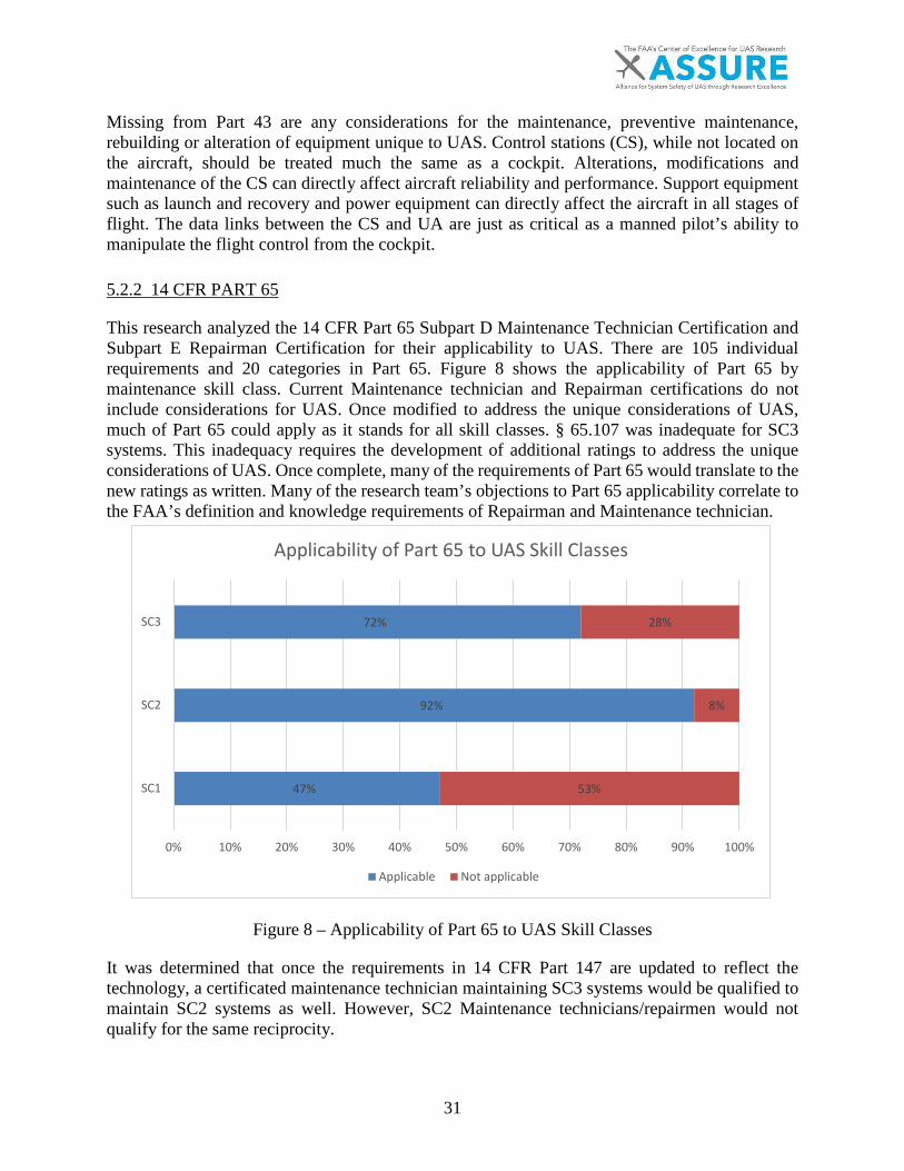
5.2.2 14 CFR PART 65
This research analyzed the 14 CFR Part 65 Subpart D Maintenance Technician Certification and Subpart E Repairman Certification for their applicability to UAS. There are 105 individual requirements and 20 categories in Part 65. Figure 8 shows the applicability of Part 65 by maintenance skill class. Current Maintenance technician and Repairman certifications do not include considerations for UAS. Once modified to address the unique considerations of UAS, much of Part 65 could apply as it stands for all skill classes. § 65.107 was inadequate for SC3 systems. This inadequacy requires the development of additional ratings to address the unique considerations of UAS. Once complete, many of the requirements of Part 65 would translate to the new ratings as written. Many of the research team’s objections to Part 65 applicability correlate to the FAA’s definition and knowledge requirements of Repairman and Maintenance technician.
Figure 8 – Applicability of Part 65 to UAS Skill Classes
It was determined that once the requirements in 14 CFR Part 147 are updated to reflect the technology, a certificated maintenance technician maintaining SC3 systems would be qualified to maintain SC2 systems as well. However, SC2 Maintenance technicians/repairmen would not qualify for the same reciprocity.
47%
92%
72%
53%
8%
28%
0% 10% 20% 30% 40% 50% 60% 70% 80% 90% 100%
SC1
SC2
SC3
Applicability of Part 65 to UAS Skill Classes
Applicable Not applicable
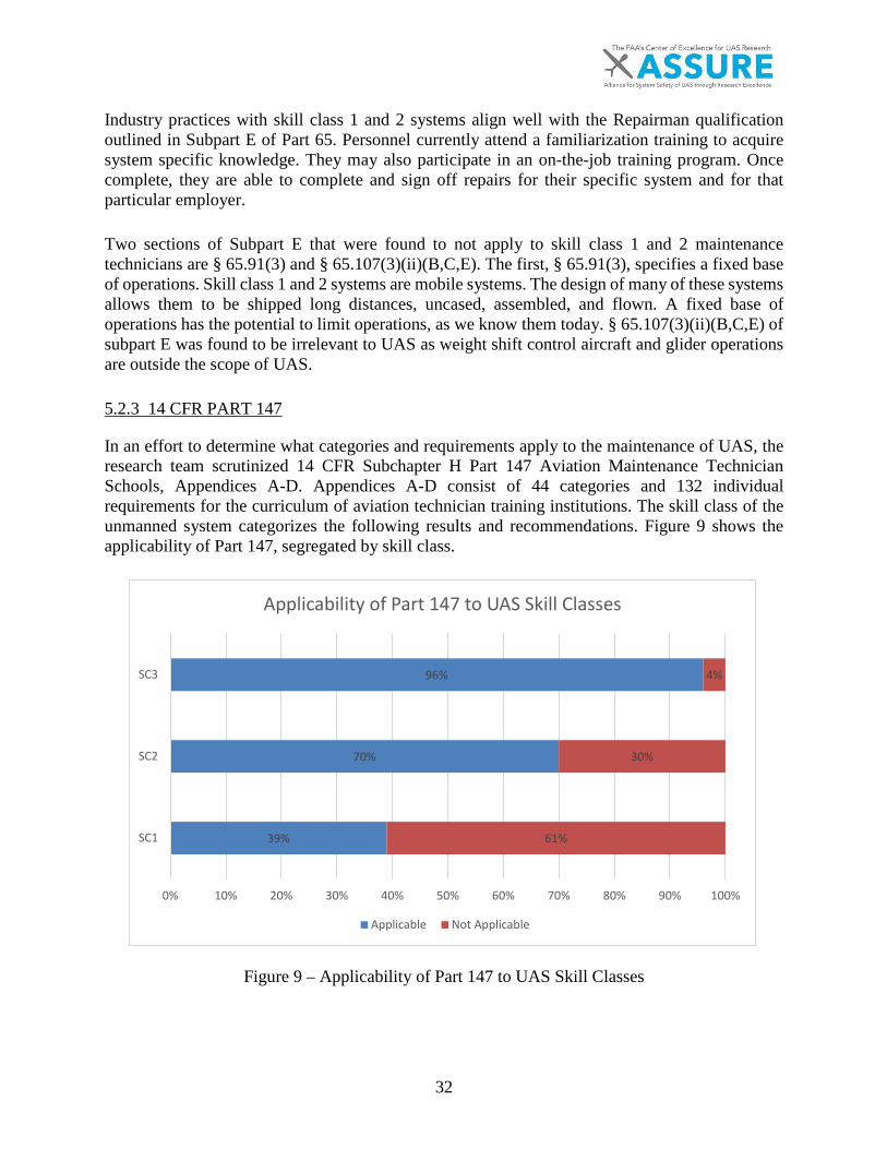
32
Industry practices with skill class 1 and 2 systems align well with the Repairman qualification outlined in Subpart E of Part 65. Personnel currently attend a familiarization training to acquire system specific knowledge. They may also participate in an on-the-job training program. Once complete, they are able to complete and sign off repairs for their specific system and for that particular employer.
Two sections of Subpart E that were found to not apply to skill class 1 and 2 maintenance technicians are § 65.91(3) and § 65.107(3)(ii)(B,C,E). The first, § 65.91(3), specifies a fixed base of operations. Skill class 1 and 2 systems are mobile systems. The design of many of these systems allows them to be shipped long distances, uncased, assembled, and flown. A fixed base of operations has the potential to limit operations, as we know them today. § 65.107(3)(ii)(B,C,E) of subpart E was found to be irrelevant to UAS as weight shift control aircraft and glider operations are outside the scope of UAS.
5.2.3 14 CFR PART 147
In an effort to determine what categories and requirements apply to the maintenance of UAS, the research team scrutinized 14 CFR Subchapter H Part 147 Aviation Maintenance Technician Schools, Appendices A-D. Appendices A-D consist of 44 categories and 132 individual requirements for the curriculum of aviation technician training institutions. The skill class of the unmanned system categorizes the following results and recommendations. Figure 9 shows the applicability of Part 147, segregated by skill class.
Figure 9 – Applicability of Part 147 to UAS Skill Classes
39%
70%
96%
61%
30%
4%
0% 10% 20% 30% 40% 50% 60% 70% 80% 90% 100%
SC1
SC2
SC3
Applicability of Part 147 to UAS Skill Classes
Applicable Not Applicable
33
Of the 44 categories and 132 requirements in Appendices A-D of Part 147, only 22 categories and 52 requirements have been determined to apply to SC1 unmanned systems (Figure 9). Even within the requirements found to apply, some do not apply to the same degree as they do for manned aircraft.
Three categories identified as categories that are fully applicable as written are: Basic Electricity, Mathematics, and Cleaning and Corrosion Control. Note that although the content is fully applicable, these categories may not fully cover the necessary curriculum to maintain unmanned systems. Basic electricity is a required knowledge item in the maintenance of UAS however; Part 147 electronics do not represent the level of knowledge necessary to maintain UAS. Focus should be on electronic theory, solid-state devices, digital circuits, and batteries. The battery curriculum should include Lithium based batteries such as Lithium Polymer (Li-Po) and Lithium Ion (Li-Ion).
An example of a category that partially applies would be the requirement to identify and select aircraft hardware and materials. SC1 technicians will need to be able to identify and select hardware and materials appropriate for their aircraft. However, aircraft grade materials and their associated naming conventions would be unnecessary.
Some categories of Part 147 do not apply at all to this skill class such as fluid lines and fittings, aircraft finishes, welding, sheet metal, landing gear systems, and cabin atmosphere control systems. Maintenance technician privileges and limitations for these categories do not apply as written.
Within Part 147 Appendix C Airframe, 38 percent (21 of the 55 listed requirements) apply to SC1. Of the 21 identified requirements, 13 should be scaled down to apply directly to SC1 systems. Of note, only SC1 aircraft tend to use wood structures and then, only as a structural reinforcement. Requirements should be scaled back to inspection of wood structures and basic servicing. SC1 uses foam, fiberglass, composite materials and thermoplastics extensively. The requirement to inspect and test these materials is a necessary skill. Repairs of these materials, excluding field applied patches, are rare as the removal and replacement of structures is common. Field patches may consist of both foam and fiberglass, although Part 147 does not address foam structures.
Only five requirements within Part 147 Appendix D Powerplant Requirements apply to SC1, however all five would need to be scaled to the UAS in this class. Balancing and installing propellers on a DJI Phantom or similar aircraft is not comparable to performing the same task on a manned platform. This is due to the size and complexity of SC1 UAS propeller assemblies being far less than that of manned aircraft propeller assemblies.
Skill class 2 (SC2) covers larger, more complex aircraft than SC1. These aircraft tend to have combustion engines, constructed of advanced composites and incorporate networking principles within the control station (CS). Within SC2, nearly 70 percent (or 93 of 132 requirements) of Part 147 is applicable as shown in Figure 9.
The 147 Appendix B General Requirements applies to SC2 nearly in its entirety. Two requirements were found not to apply (except in specific use cases): performing basic heat-treating and inspecting / checking welds with metallic aircraft. Current industry trends indicate that most SC2
34
aircraft are not constructed of metallic parts, therefore metallic aircraft requirements are likely unnecessary.
As previously discussed, there may be a need to scale applicable requirements to meet the requirements of the aircraft. The SC2 aircraft are often around a specific payload or mission. This limits, but does not eliminate weight and balance requirements. The associated procedures can vary widely between different unmanned aircraft (UA) and between unmanned and manned aircraft.
Ground operations and servicing is another category that must scale to a particular airframe. The SC2 aircraft can vary from an Insitu Scan Eagle-type aircraft that can be hand carried by an individual crewmember, to an Aerosonde or RQ-7B “Shadow,” that can weigh upwards of 300 lbs. Regardless of where on the spectrum a SC2 airframe falls, ground operations and servicing are different from manned aircraft. SC2 aircraft are often carried or maneuvered on the ground by hand without the use of the engine. Non-traditional fuel ranging from 87 octane unleaded motor gas to C-1 racing fuel may be used. Some aircraft in this skill class may use traditional 100 low lead aviation gas. Fueling procedures may involve pulling a vacuum on the fuel bladders before fueling or simply filling a fuselage-mounted tank in much the same way you would fuel an all-terrain vehicle or lawn mower.
Within Part 147 Appendix C Airframe, 67 percent (or 38 of 56) of requirements have been found to be applicable for SC2. Traditionally, sheet metal is rarely, if ever, used on SC2 aircraft. The added weight, over advanced composite materials, directly contributes to limitations in payload capacity and flight time. The requirement of Appendix C to be able to rivet, shape, inspect and repair sheet metal is unlikely to apply to airframes themselves, instead support equipment inspection and repair may utilize these skills. Metallic support equipment trends towards launch and recovery devices, fuel carts, and ground power units, which may have very small tolerances due to the requirements for safe operation. Inspections are commonly required, but metallic repair or welding may be prohibited per manufacturer instructions.
Part 147 Appendix D, Powerplant includes 43 requirements, of which nearly 56 percent (or 24 of 43) are applicable to SC2. Power plants within SC2 tend to be small combustion enginesrepurposed or designed specifically for a specific airframe. Rotary and 2-stroke engines arecommon due to their high power to weight ratio. These engines are less complex and contain fewermoving parts than traditional manned aviation engines contributing to a further decrease in weightand maintenance complexity.
35
A total of 96 percent (or 127 requirements) of Part 147 was found to be applicable to skill class 3 (SC3) systems (Figure 9). The only categories found not to be applicable were wood structures, unducted fans and radial engines. Sections of Part 147 would only be applicable within optionally piloted aircraft or passenger carrying UAS. Subjects regarding cabin pressurization, oxygen systems, seating, etc. would fall into this category. With the removal of passenger requirements on board the SC3 UAS, 16 further requirements would not apply to SC3 UAS as used today.
Part 147 will need an update to become current with new technology. There is no mention of computer concepts such as hard drives, motherboards, permissions, software or firmware. With UAS, while there is a human in the loop, computers are the actual pilots responsible for moving the flight surfaces and as such, their maintenance is a critical concept. Computer networking is one of the mechanisms by which electronic equipment communicates. Without that communication, some of the built-in redundancies with UAS are lost. The flight physics of multirotor aircraft is another important concept not covered in Part 147. Part 147 covers the physics behind single propellers well. However, Part 147 must expand to include the physics behind the relationship of each rotor to the aircraft as a whole in a multirotor system such as a quad or hex copter.
Research discussions about non-metallic materials highlighted the current use of foam applications in UAS today. SC1 aircraft commonly use foam for various applications; however, it is unlikely that SC1 aircraft will see wide use outside of the applications and limitations of Part 107. Further, outside of foam gluing procedures and the use of specialty tapes, foam is cheap and simple to remove and replace as necessary.
One research discussion about software highlighted the importance of 43.3(k) database updates. Unlike manned aircraft where the failure of a navigational aide or similar piece of equipment is unlikely to cause a complete aircraft failure, the software in a UAS is the primary driver of the system. If a piece of avionics equipment fails, it is possible to encounter a catastrophic failure of an unmanned system.
Another discussion item was the applicability of major and minor alterations and repairs, especially within SC1 and SC2 UAS. Many systems within these classes are repaired in a manner that could be defined as a major alteration or repair of the aircraft under the existing definition. The regular removal and replacement of propellers is one such example. The research team classified this activity as a major alteration or repair, as it could have dramatic effects on the aircraft in flight. It was also determined that there was a case for calling it a major repair or alteration without applying the associated administrative procedures. Requirements such as these may have to be addressed from an operational risk perspective rather than from a maintenance perspective. Line of sight operations in a crowded environment may necessitate more strict maintenance controls than line of site (or even beyond line of sight) operations over a sparsely populated area.
5.3 INTERNATIONAL STANDARDS
This study reviewed many international standards for applicability. EASA’s Part-66 was the chosen international standard due to its recent updates. Upon selecting this standard, the research team analyzed it in order to identify any existing gaps. Although several of the requirements did

36
not apply in the United States, the research team identified similarities between FAA standards and EASA standards, as shown in Figure 10.
Figure 10 – Applicability of EASA Part-66 to UAS Skill Classes
Part-66 is applicable to SC1 systems for 412 requirements of the 1007 addressed. Five of the 412 applicable requirements were general, and they apply to all aircraft regardless of skill class. Basic aircraft theory and terminology are examples of required training that apply to all airframes even though they might be designed for specialized applications. Many of the areas found not to apply were based on skill class 1 aircraft. Technologies such as fiber optic communications equipment are not relevant to sUAS due to a lack of control systems and communications requirements that might need large distances between aircraft and operator. Another example relates directly to aircraft structures. Knowledge of large aircraft manufacturing techniques, reinforcement techniques, and bulkhead construction procedures are areas that are generally not applicable to SC1.
41%
61%
89%
59%
39%
11%
0% 10% 20% 30% 40% 50% 60% 70% 80% 90% 100%
SC1
SC2
SC3
Applicability of EASA Part-66 to UAS Skill Classes
Applicable Not Applicable

37
A total of 614 requirements from Part-66 are applicable to SC2 UAS. Just as found in the SC1 gap analysis, many of the requirements found to be not applicable related to aircraft construction. Within the scope of SC2, fire protection, cabin layout, and other flight control systems were not applicable. It is important to note that the research team excluded ice and rain protection systems from both SC1 and SC2 knowledge areas because of the performance envelope in which these aircraft operate. SC1 and SC2 also share a common is a lack of applications for heavy hydraulic power systems due to size and composition of aircraft.
A total of 892 requirements are applicable to SC3 systems. In the SC3 area, many of the requirements are same for a comparable manned aircraft of size and weight. The primary differences in dealing with SC3 unmanned aircraft is, again, in aircraft equipment that directly support passengers. Cabin furniture, environmental systems and pressurization are a few systems that are not applicable.
As was mentioned previously, the largest group of requirements that did not apply addressed who can maintain and return the system to service. All of Appendices D and F of Part 43 are applicable, while Appendix F applicability varies based on equipage. Some requirements are payload dependent, and consist of maintenance involving windows, seat belts, seats, and front instrument panel-mounted devices. These requirements only apply when the UA carries passengers or is optionally piloted.
The research team notes the exclusion of aircraft legislation and airworthiness requirements in all skill classes because they are not applicable in the United States. The exception to this is the applicability of Part 145 and the role of the International Civil Aviation Organization (ICAO).

38
6. RECOMMENDATIONS
Recommendations for UAS maintenance technician training certification requirements are based on the results of the gap analysis, four in-depth analysis reports, and the UAS related specification and standards. Figure 11 summarizes the totals of the three FAA CFR’s including Part 43, Part 65 and Part 147 based on the findings in the gap analysis in Section 5. as related to skill classes 1, 2 and 3.
Figure 11 –UAS Skill Class Applicability to CFRs from Gap Analysis
Part 147 was prioritized out of the three CFR’s to define the specific recommended UAS skills because of the curriculums listed in the three appendices:
• Appendix B General Curriculum Subjects• Appendix C Airframe Curriculum Subjects• Appendix D Powerplant Curriculum Subjects.
The final list of skill recommendations contains the skills identified in Part 147 with the added skills recommended for UAS maintenance technicians. Refer to Figure 12 for the total recommended skills to effectively create the certification requirements for UAS maintenance technicians. Table 15 summarizes the task knowledge required for UAS Maintenance Training based on the four in-depth analyses, which was used to identify the UAS skill quantities listed in Figure 12. Using the assumptions created for the three-skill classes in Table 14, Skill class 1 requires a total of 67 skills: 52 are identified in Part 147, while 15 are specific to UAS. Skill class 2 requires a total of 119 skills: 93 are identified in Part 147, while 26 are UAS specific. And finally skill class 3 identifies a total of 150 skills: 127 are identified in Part 147, while 23 are related to UAS.
42%
84%
87%
58%
16%
13%
0% 10% 20% 30% 40% 50% 60% 70% 80% 90% 100%
SC1
SC2
SC3
UAS Skill Class Applicability to CFRs from Gap Analysis
Applicable Not Applicable

39
Figure 12 – Total Recommended Skills per Skill Class for CFR Part 147
The in-depth analysis reports present recommendations for the UAS maintenance technicians as detailed in the following sections: section 6.1 to 6.5. The UA section contains additional content not derived directly from in an in-depth analysis, but was discovered while studying the ASTM documents. As stated above, all of the findings in the following sections are summarized in Table 15, which is located in Appendix B – Recommended UAS Skills.
6.1 THE UNMANNED AIRCRAFT (UA)
Many of the studies in this document relate to the UA, but the primary items discussed below are the considerations for repairing non-metallic materials and batteries. Refer to later sections for software, autopilot and communications considerations related to UAs.
For non-metallic structures for UA it is recommended to repair composites in the same fashion as currently defined in manned aviation while other materials like thermoplastics, foam, wood, and fabric still lack regulations to define effective repair procedures. There are many methods available to repair thermoplastics, but their repair will not restore full strength. Remove and replace is preferred for all UAS due to ease of replacement, to avoid expensive equipment, and checks required to validate that the repair was sufficient.
Many types of foam currently exist including Expanded polypropylene (EPP) and Expanded Polyolefin (EPO) foam, which are common in small UA (sUA). The EPO and EPP often comprise the entire structure of the UA, and are sometimes used to encase the wing in order to save weight. For the purposes of this report, the latter application was not explored.
52
93
127
15
26
23
0 20 40 60 80 100 120 140 160
SC1
SC2
SC3
Total Recommended Skills per Skill Class for 14 CFR Part 147
Part 147 UAS

40
The ASTM F3005-14a battery standard [11] provides the sufficient information for maintaining batteries. The damage evaluation recommendations are helpful defining checks for electrolyte leakage, odor, puncture or crushed casing, severe swelling, and mechanically stressed electrical connectors. The ASTM F3005-14a recommends a routine evaluation of 100 cycles during normal operations in Section 8.1.2 of F3005-14a to check the following:
(1) Test marking high utilization procedures to ensure retentions of adequate capacity,
(2) Low utilization procedures when a battery is stored for three months or more, and
(3) A service limitation if a battery lost 20% of the rated capacity to discard the battery.
In summary, skill recommendations for the UA require an in-depth understanding about battery inspections due to the reliability of the sUAS’s typical power supply on electricity and familiarity with all structural materials in order to properly perform an inspection to identify anomalies, whether pre-flight, post-flight or unscheduled. Refer to the existing manned aviation standard AC65-33 when repairs for composites are necessary.
6.2 CONTROL STATIONS (CS) AND SUPPORT EQUIPMENT
Refer to Table 12 for the list of primary skills identified for Control Stations (CS) and support equipment. The following table is from "Task 4c(ii) Report: In-Depth Analysis of Control Systems and Support Equipment," but is shown here to define the recommendations generated by that report. Table 12 shows the full list of recommended skills. Skills covered by AC 65-2D are denoted by a black solid bullet point [•] while skills not found in the AC 65-2D are denoted by an arrow [].
Table 12 – Primary Skills for CS and Support Equipment
Microcomputers Troubleshoot, service, check, remove, install and clean microcomputer hardware Troubleshoot, service, remove and install microcomputer operating systems Troubleshoot, remove, install, check and clean microcomputer peripherals (printers, input,
storage devices, etc….) Check for and remove threats to microcomputers and networks Service, remove, install and check data storage devices Service, check and navigate CS software Understand command line interface Troubleshoot device drivers Troubleshoot video distribution and displays Troubleshoot serial connections Understand encryption and password management
Networks
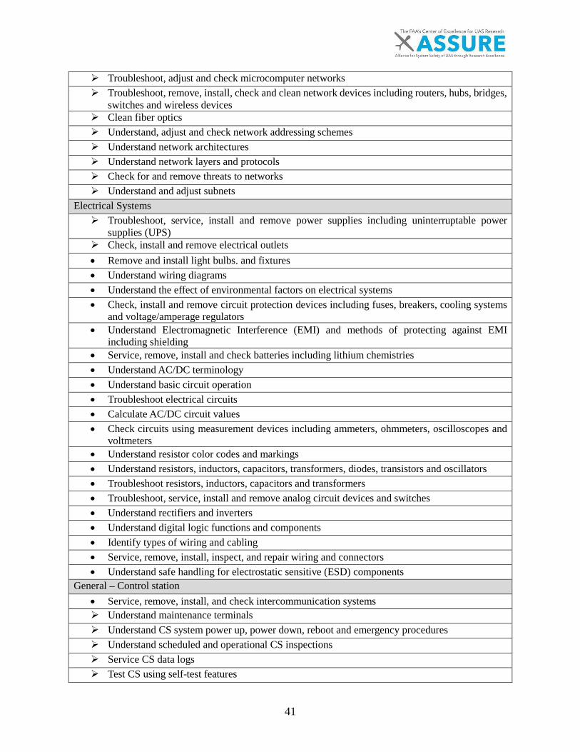
41
Troubleshoot, adjust and check microcomputer networks Troubleshoot, remove, install, check and clean network devices including routers, hubs, bridges,
switches and wireless devices Clean fiber optics Understand, adjust and check network addressing schemes Understand network architectures Understand network layers and protocols Check for and remove threats to networks Understand and adjust subnets
Electrical Systems Troubleshoot, service, install and remove power supplies including uninterruptable power
supplies (UPS) Check, install and remove electrical outlets • Remove and install light bulbs. and fixtures • Understand wiring diagrams • Understand the effect of environmental factors on electrical systems • Check, install and remove circuit protection devices including fuses, breakers, cooling systems
and voltage/amperage regulators • Understand Electromagnetic Interference (EMI) and methods of protecting against EMI
including shielding • Service, remove, install and check batteries including lithium chemistries • Understand AC/DC terminology • Understand basic circuit operation • Troubleshoot electrical circuits • Calculate AC/DC circuit values • Check circuits using measurement devices including ammeters, ohmmeters, oscilloscopes and
voltmeters • Understand resistor color codes and markings • Understand resistors, inductors, capacitors, transformers, diodes, transistors and oscillators • Troubleshoot resistors, inductors, capacitors and transformers • Troubleshoot, service, install and remove analog circuit devices and switches • Understand rectifiers and inverters • Understand digital logic functions and components • Identify types of wiring and cabling • Service, remove, install, inspect, and repair wiring and connectors • Understand safe handling for electrostatic sensitive (ESD) components
General – Control station • Service, remove, install, and check intercommunication systems Understand maintenance terminals Understand CS system power up, power down, reboot and emergency procedures Understand scheduled and operational CS inspections Service CS data logs Test CS using self-test features
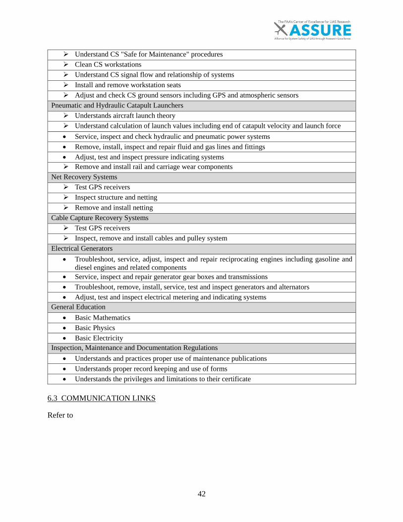
42
Understand CS "Safe for Maintenance" procedures Clean CS workstations Understand CS signal flow and relationship of systems Install and remove workstation seats Adjust and check CS ground sensors including GPS and atmospheric sensors
Pneumatic and Hydraulic Catapult Launchers Understands aircraft launch theory Understand calculation of launch values including end of catapult velocity and launch force • Service, inspect and check hydraulic and pneumatic power systems • Remove, install, inspect and repair fluid and gas lines and fittings • Adjust, test and inspect pressure indicating systems Remove and install rail and carriage wear components
Net Recovery Systems Test GPS receivers Inspect structure and netting Remove and install netting
Cable Capture Recovery Systems Test GPS receivers Inspect, remove and install cables and pulley system
Electrical Generators • Troubleshoot, service, adjust, inspect and repair reciprocating engines including gasoline and
diesel engines and related components • Service, inspect and repair generator gear boxes and transmissions • Troubleshoot, remove, install, service, test and inspect generators and alternators • Adjust, test and inspect electrical metering and indicating systems
General Education • Basic Mathematics • Basic Physics • Basic Electricity
Inspection, Maintenance and Documentation Regulations • Understands and practices proper use of maintenance publications • Understands proper record keeping and use of forms • Understands the privileges and limitations to their certificate
6.3 COMMUNICATION LINKS
Refer to

43
Table 13 for the list of primary skills identified for communication links. This table is an excerpt of "Task 4c(iii) Report: In-Depth Analysis of Communication Links," located in 0. Table 13 defines the recommendations generated by that report. Skills covered by AC 65-2D are denoted by a black solid bullet point [•] while skills not found in the AC 65-2D are denoted by an arrow []. Skills partially covered by AC 65-2D are denoted by an open bullet point [○].

44
Table 13 – Primary Skills
Basic Radio Principles Understand frequency bands and their common uses Understand radio terms and components including receiver sensitivity, tuning circuits,
amplifiers, oscillators, modulators, demodulators, and filters
• Understand FAA and FCC radio regulationsAntennas, Transmission Lines and Antenna Trackers
o Troubleshoot, remove, install, adjust and inspect antennas including satellite communicationsantennas
Understand antenna variants Troubleshoot, service, adjust and check antenna trackers Understand antenna tracker operations• Remove, install, inspect and repair transmission lines Understand types of transmission line, velocity factor, impedance and voltage standing wave
ratioRadio Monitoring Remove, install and check spectrum analyzers Remove, install and check radio frequency monitors
Transmitting and Receiving o Remove, install, adjust and check transmitters, receivers and transceivers Configure and check satellite loopbacks and reach back loops Configure and check functionality of link integrity and self-testing functions Troubleshoot broken and degraded communication links Remove, install, adjust and check amplifiers and attenuators
Electrical Systems Troubleshoot, service, install and remove power supplies including uninterruptable power
supplies (UPS) Check, install and remove electrical outlets• Remove and install light bulbs. and fixtures• Understand wiring diagrams• Understand the effect of environmental factors on electrical systems• Check, install and remove circuit protection devices including fuses, breakers, cooling systems
and voltage/amperage regulators• Understand Electromagnetic Interference (EMI) and methods of protecting against EMI
including shielding• Service, remove, install and check batteries including lithium chemistries• Understand AC/DC terminology• Understand basic circuit operation• Troubleshoot electrical circuits• Calculate AC/DC circuit values• Check circuits using measurement devices including ammeters, ohmmeters, oscilloscopes and
voltmeters
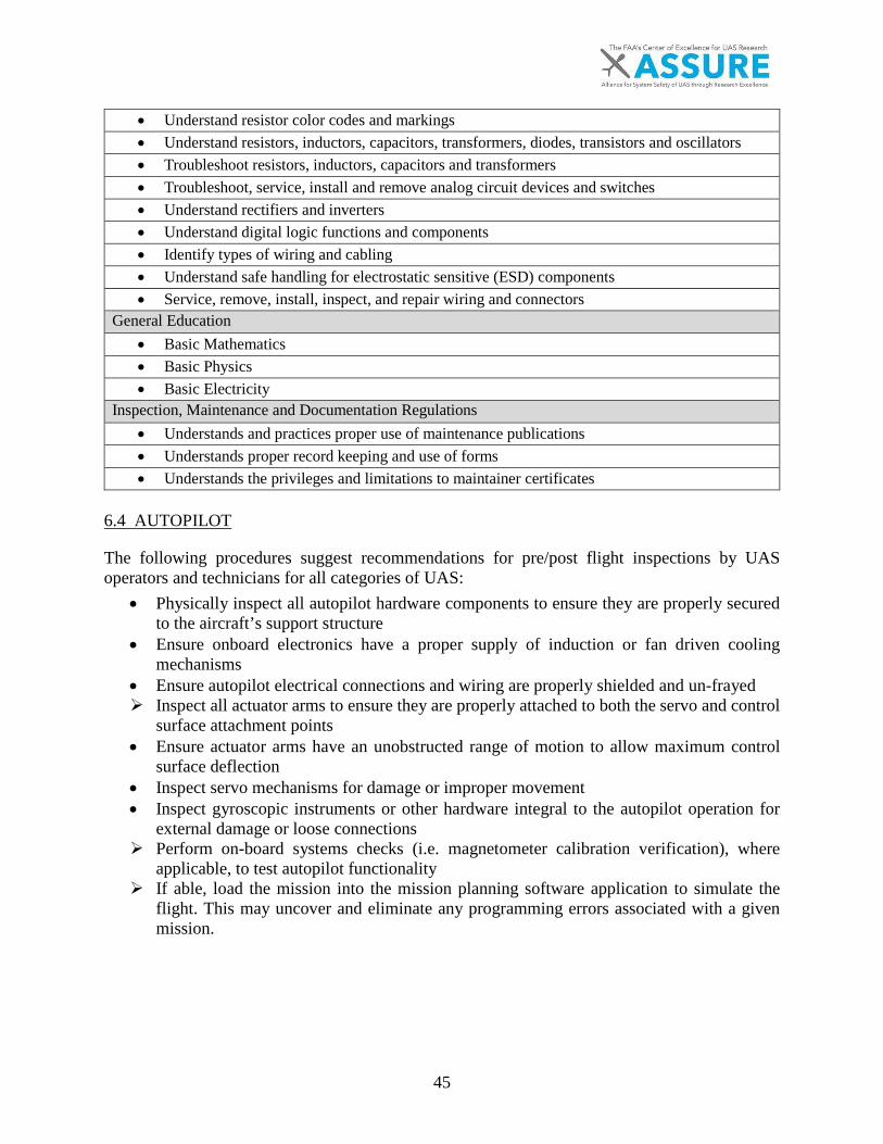
45
• Understand resistor color codes and markings• Understand resistors, inductors, capacitors, transformers, diodes, transistors and oscillators• Troubleshoot resistors, inductors, capacitors and transformers• Troubleshoot, service, install and remove analog circuit devices and switches• Understand rectifiers and inverters• Understand digital logic functions and components• Identify types of wiring and cabling• Understand safe handling for electrostatic sensitive (ESD) components• Service, remove, install, inspect, and repair wiring and connectors
General Education • Basic Mathematics• Basic Physics• Basic Electricity
Inspection, Maintenance and Documentation Regulations • Understands and practices proper use of maintenance publications• Understands proper record keeping and use of forms• Understands the privileges and limitations to maintainer certificates
6.4 AUTOPILOT
The following procedures suggest recommendations for pre/post flight inspections by UAS operators and technicians for all categories of UAS:
• Physically inspect all autopilot hardware components to ensure they are properly securedto the aircraft’s support structure
• Ensure onboard electronics have a proper supply of induction or fan driven coolingmechanisms
• Ensure autopilot electrical connections and wiring are properly shielded and un-frayed Inspect all actuator arms to ensure they are properly attached to both the servo and control
surface attachment points• Ensure actuator arms have an unobstructed range of motion to allow maximum control
surface deflection• Inspect servo mechanisms for damage or improper movement• Inspect gyroscopic instruments or other hardware integral to the autopilot operation for
external damage or loose connections Perform on-board systems checks (i.e. magnetometer calibration verification), where
applicable, to test autopilot functionality If able, load the mission into the mission planning software application to simulate the
flight. This may uncover and eliminate any programming errors associated with a givenmission.
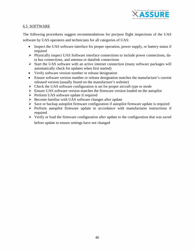
46
6.5 SOFTWARE
The following procedures suggest recommendations for pre/post flight inspections of the UAS software by UAS operators and technicians for all categories of UAS:
• Inspect the UAS software interface for proper operation, power supply, or battery status ifrequired
Physically inspect UAS Software interface connections to include power connections, da-ta bus connections, and antenna or datalink connections
Start the UAS software with an active internet connection (many software packages willautomatically check for updates when first started)
• Verify software version number or release designation• Ensure software version number or release designation matches the manufacture’s current
released version (usually found on the manufacture’s website) Check the UAS software configuration is set for proper aircraft type or mode Ensure UAS software version matches the firmware version loaded on the autopilot Perform UAS software update if required Become familiar with UAS software changes after update Save or backup autopilot firmware configuration if autopilot firmware update is required Perform autopilot firmware update in accordance with manufactures instructions if
required Verify or load the firmware configuration after update to the configuration that was saved
before update to ensure settings have not changed

47
7. CONCLUSION
Scalable Requirements The requirements for training UAS maintenance technicians vary greatly due to the large variety of configurations of UAS, which relates to the recent explosive growth in the industry. As outlined in the four in-depth analyses, it is possible to define new levels of system taxonomy to understand each element of the unmanned aircraft system (UAS).
The differences between manned and unmanned aviation vary greatly due to new applications of older technologies, new technologies and new variations of combined technologies. Using a 3-tier skill level system, as defined in Table 10, a baseline is established that differentiates the varying levels of applicability of manned to unmanned while identifying the missing training components required for UAS maintenance. The 3-tier skill level Appendix A – UAS Maintenance Skill Class table, located in Appendix A, defines key elements that comprise UAS maintenance.
The implication of these key differences between manned aviation to the current UAS industry can affect training and certification depending on the process of integrating UAS in the National Airspace System (NAS). Using the 3-tier system as defined today, a preliminary methodology that is scalable for integration of UAS maintenance training requirements is possible by creating regulation for the least risky certifications first (e.g. license SC1 for sUAS).
Unique UAS Considerations In addition to providing a potentially scalable UAS maintenance-training requirement, there are many unique considerations for specific UAS systems.
Non-metallic structures for Unmanned Aircraft (UA) contain some unique considerations with many being the same as currently defined in manned aviation. For UAs that receive repairs for composites, repairs are completed in the same fashion as currently defined in manned aviation. Other materials researched include thermoplastics, foam, wood, and fabric, which utilize varying repair techniques.
Thermoplastics have many existing methods for repair, such as fusion and resistance welding. However, removal and replacement of damaged parts is favored over repair for all UAS. The emphasis on removal and replacements is due to ease of replacement and avoidance of expensive equipment and checks required to validate the repair was sufficient. Foam construction is common in small UA (sUA) as often makes up the entire structure in order to save weight.
Advanced composites are common use items within UAS. Non-destructive testing and repair of these materials are a critical component within SC2 and SC3 UAS. A concentration on this aspect of non-metallic structures and a proportional reduction in emphasis with other fabrics and organic materials may be warranted.
Control station (CS) and support equipment add many unique maintenance elements that are different from manned aircraft. One of the particularly unique aspects of CS is the sub-components that make up the system. Compared to traditional aviation, consumer electronics and microcomputers are designed for more than a pilot interface. Microcomputers create a need for

48
computer networks that are unfamiliar to manned aviation. The presence of these components in CS and the lack of training an aircraft maintenance technician has in these areas create a requirement for the training of maintenance technicians.
Along with the skills and knowledge, an aircraft maintenance technician may not be familiar with, CS and support equipment present unique aspects to maintenance. Though physically separate, CS and support equipment are part of the complete unmanned aircraft system and must be maintained as such. Testing and checking the UAS will sometimes require utilization of multiple separate parts of the system, testing them together: e.g. test both of the flight operation UA and CS together to verify all components in the communication system work correctly by transmitting and receiving from the UA to the corresponding CS.
The method that components of the UAS experience wear will differ greatly as the environment the CS, support equipment and the operational environment UA are exposed can differ greatly. This creates a need, not only for training in the skills needed to maintain CS and support equipment, but also for familiarization training for maintenance technicians to facilitate an understanding that an unmanned aircraft system is a part of a complete system with separate pieces that have to be maintained independently in order for the entire system to function effectively.
UAS communication links present several unique maintenance elements despite having several similarities to manned aviation radios. Unlike manned aviation, the maintainer of a UAS must maintain both the sending and receiving ends of a radio transmission. These systems, though physically separate, are still parts of the same communication link system and must be maintained as a system to ensure safe and successful operations. Maintenance of the communication link system requires collaboration between the surface elements and the UA. In addition, differing environmental conditions on the surface and airflow factors may cause more or less wear on that element of the system.
An aircraft maintenance technician may be familiar with many aspects of a communication link system but will still require additional training to perform the specific skills unique to maintaining communication links. Aircraft maintenance technician training in voice communication and navigation radio systems, along with a background in electrical systems, will provide maintenance technicians with most of the skills required to maintain communication links. Training would still be required to acquire troubleshooting skills and to test UAS communication links and maintain satellite links as well as antenna tracking mounts. Additional training in these areas for an aircraft maintenance technician would help achieve the final goal of a highly qualified UAS maintainer that is prepared to work with these systems.
Maintainer and technician requirements for UAS autopilot and software applications also vary greatly by system as a direct result of complexity. The software and intended application of the system heavily influences the functionality of the autopilot. Recommendations made as part of this report provided the most up-to-date data available for the research team. Each of the systems analyzed represent similarities as well as nuances that define maintainer and technician requirements.
49
Recommended Certification Requirements Based on Existing Regulations There are many similarities when comparing existing manned regulations to UAS maintenance training as understood today. The FAA’s 14 CFR Part 43 Maintenance, preventive maintenance, rebuilding and alteration has some applicability, as currently written, to UAS of every skill class with the exception of those covered under 14 CFR Part 107. Approximately 56% of Part 43 applies for SC1, 84% for SC2, and 86% for SC3 and references to 14 CFR Parts 91, 121, 125, 129 and 135, each of which must update to include UAS considerations.
The FAA 14 CFR Part 65, EASA 66 and 14 CFR Part 147 were also reviewed for applicability. Part 65 refers to maintenance technicians and repairmen as defined by the FAA, whereas the light sport certificate with maintenance and light sport certificate with inspection certificate requirements outlined in Part 65 could be applicable to skill class 1, 2 and 3 systems with some modification of the knowledge requirements.
Even though EASA Part-66 consists of a list that is more comprehensive than other requirements, there are still commonalities in the three skill classes. As aircraft increase in size and complexity, the requirements for both unmanned and manned aircraft converge. Due to EASA Part-66 aircraft type specific requirements, it is likely that technicians will be required to continue to learn as aircraft evolve in terms of specification and operational envelopes. As EASA requirements evolve, it is apparent that the organization will focus on how, and under what conditions unmanned aircraft will be used, rather than the characteristics of the airframe alone.
An update to 14 CFR Part 147 and Advisory Circular 65-2D would allow for the application of Part 65 maintenance technician references to apply to SC2 and SC3 UAS. The largest gap within skill class one (SC1) requires computer and networking training, as well as a broader understanding of electronics such as integrated chipsets, modulation techniques, microcontrollers and electronic servos, flight controllers and even operational aspects, as defined within Part 107.
The final UAS maintenance technician training certification requirements were created using Part 147 as a benchmark. Skill class 1 requires a total of 67 skills: 52 are currently identified in Part 147, while 15 are specific to UAS. Skill class 2 requires a total of 119 skills: 93 are identified in Part 147, while 26 are UAS specific. And finally skill class 3 identifies a total of 150 skills: 127 are identified in Part 147, while 23 are related to UAS.
Data represented throughout this report indicate that specific content and skills are required to properly maintain, service, or replace the majority of autopilot and software systems that are currently on the market. The further development of standards and protocols related to airworthiness and certification will likely confine manufacturers to stricter guidance regarding the operational characteristics and performance of these systems adding requirements to maintain a condition for safe operation.
In conclusion, the three-tier UAS certification methodology recommended in this report provides a scalable road map to address the gap of missing skill requirements related to UAS maintenance (Refer to Table 14 – UAS Maintenance Skill Class for detailed assumptions). Using Part 147 as a benchmark with the added UAS skills in Figure 12 can enable the FAA to modify existing regulations as needed. The modified regulations will help the FAA safely introduce UAS with varying UA, system and operation types into the National Airspace System (NAS).
50
8. BIBLIOGRAPHY
[1] FAA. (1996, January) FAA Historical Chronology, 1926-1996. [Online].https://www.faa.gov/about/media/b-chron.pdf
[2] James V. Jones, Integrated Logistics Support Handbook, Third Edition ed., Larry S. Hager,Ed. New York, New York, US: Sole Logistics Press, McGraw-Hill, 2006.
[3] GPO US Publishing Office. (2017, June) Title 14, Chapter I, Subchapter A, Part 1, 1.1.[Online]. https://www.ecfr.gov/cgi-bin/text-idx?SID=4b6e54f951d54183dcde7d6c7aee0918&mc=true&node=se14.1.1_11&rgn=div8
[4] ASTM International. (2015, November) ASTM 2911-14a - Standard Practice forProduction Acceptance of Small Unmanned Aircraft System (sUAS). [Online].https://www.astm.org/Standards/F2911.htm
[5] Neil B. Bloom, Reliability Centered Maintenance, 1st ed., Kenneth McCombs, Ed. NewYork, New York: The McGraw-Hill Companies, 2006.
[6] D. M. Marshall, R. K. Barnhart, E. Shappee, and M. Most, Introduction to UnmannedAircraft Systems (2nd edition), Second Edition ed., D. M. Marshall et al., Eds. Boca Raton:Taylor & Francis, CRC Press, 2016.
[7] ASTM International. (2016, August) ASTM F2908-16 - Standard Specification for AircraftFlight Manual (AFM) for a Small Unmanned Aircraft System (sUAS). [Online].https://www.astm.org/Standards/F2908.htm
[8] ASTM International. (2015, October) ASTM F2909-14, Standard Practice for Maintenanceand Continued Airworthiness of Small Un-manned Aircraft Systems (sUAS).
[9] ASTM International. (2016, January) ASTM F2910-14 - Standard Specification for Designand Construction of a Small Unmanned Aircraft System (sUAS). [Online].https://www.astm.org/Standards/F2910.htm
[10] ASTM International. (2015, November) ASTM F3002-14A: Standard Specification forDesign of the Command and Control System for Small Unmanned Aircraft Systems(sUAS). document.
[11] ASTM International. (2015, November) ASTM F3005-14a - Standard Specification forBatteries for Use in Small Unmanned Aircraft Systems (sUAS). [Online].https://www.astm.org/Standards/F3005.htm
[12] (2016) Association for Unmanned Vehicle Systems International – UAS PlatformDatabase.
[13] Northland Community Technical College, Space Tec. (2016, June) DACUM ResearchChart for UAS Maintenance Technicians. [Online].http://www.northlandcollege.edu/aerospace/dronetech/UASMxDACUM.pdf
[14] Jr, Henry H, and Eliot O Sprague Perritt. (2016, June) Domesticating Drones. [Online].https://ebookcentral.proquest.com/lib/erau/detail.action?docID=4684221
[15] A Hobbs and S. R. Herwitz, Human Challenges in the Maintenance of Unmanned AircraftSystems.: FAA and NASA Report, 2006.
[16] A., & Shively, R. J. Hobbs, Human Factor Challenges of Remotely Piloted AircraftAvailable at http://human-factors. arc. nasa. gov/publications/Hobbs_EAAP. pdf.: NASA,2014.
51
[17] A., & Herwitz Hobbs, Human Factors in the Maintenance of Unmanned Aircraft. Small,15(100)., 2014.
[18] A., & Herwitz Hobbs, Maintenance Challenges of Small Unmanned Aircraft Systems - AHuman Factors Perspective. doi:10.13140/RG.2.1.1858.8647., 2008.
[19] UL LLC. (2016, December) UL 3030 Outline of Investigation for Unmanned AerialVehicles. [Online]. https://standardscatalog.ul.com/standards/en/outline_3030_1
[20] U.S. Air Force Fact Sheets @ http://www.af.mil/AboutUs/FactSheets.aspx.[21] U.S. Army Unmanned Aircraft Systems Repairer (15E) (n.b.) career profile. [Online].
http://www.goarmy.com/careers-and-jobs/browse-career-and-job-categories/transportation-and-aviation/unmanned-aircraft-systems-repairer.html
[22] U.S. Army Unmanned Aircraft Systems Operator (15W) (n.d.) career profile. [Online].http://www.goarmy.com/careers-and-jobs/browse-career-and-job-categories/transportation-and-aviation/unmanned-aerial-vehicle-operator.html
[23] U.S. Air Force Remotely Piloted Aircraft Maintenance career profile @https://www.airforce.com/careers/detail/remotely-piloted-aircraft-maintenance.
[24] U.S. Marines MOS 6314 Avionics/Maintenance Technician, Unmanned Aircraft System(UAS) career profile. [Online]. http://www.cool.navy.mil/usmc/enlisted/6314.htm
[25] Kurt Barnhart, Stephen Ley, Tim Bruner, Mike Most, and Andrea Meyer, "Draft TechnicalReport of UAS Maintenance Data Preliminary Analysis," Manhattan, Research document2016.
[26] Zachary, Nick, Charles, Meyer, Andrea, Barnhart, Dr. Kurt Nicklin, "Survey Results andTechnical Review of UAS Maintenance Technician Training Standards ," Kansas StateUniversity, Manhattan, Research paper 2017.
[27] NCATT. (2012) Unmanned Aircraft System (UAS) Maintenance Standard, NationalCenter for Aerospace and Transportation Technologies. Document.
[28] FAA. (2017, May) 333 COA CS and Comm Incident Acccident Database. Document.[29] United States Air Force. (2011, January) Aircraft Accident Investigation Board Report.
Document.[30] Northland Community and Technical College, Northland Aerospace- Modified Shelter
Task List., 2017.[31] US Government Publishing Office. (2011) CFR 14, Part 147: Aviation Maintenance
Technician Schools.[32] FAA. (1976, January) FAA.gov. [Online].
https://www.faa.gov/documentLibrary/media/Advisory_Circular/AC_65-2D.pdf[33] GPO US Government Publishing Office. (2017, June) 14 CFR Part 43. [Online].
https://www.ecfr.gov/cgi-bin/text-idx?SID=fc277b3608094d2c4597bcfef0008c60&mc=true&node=pt14.1.43&rgn=div5
[34] Europe Aviation Safety Agency. (2017, June) Aircraft Type Ratings for Part-66 aircraftmaintenance licence. [Online]. https://www.easa.europa.eu/easa-and-you/aircraft-products/continuing-airworthiness-organisations/aircraft-type-ratings-part-66-aircraft-maintenance-licence
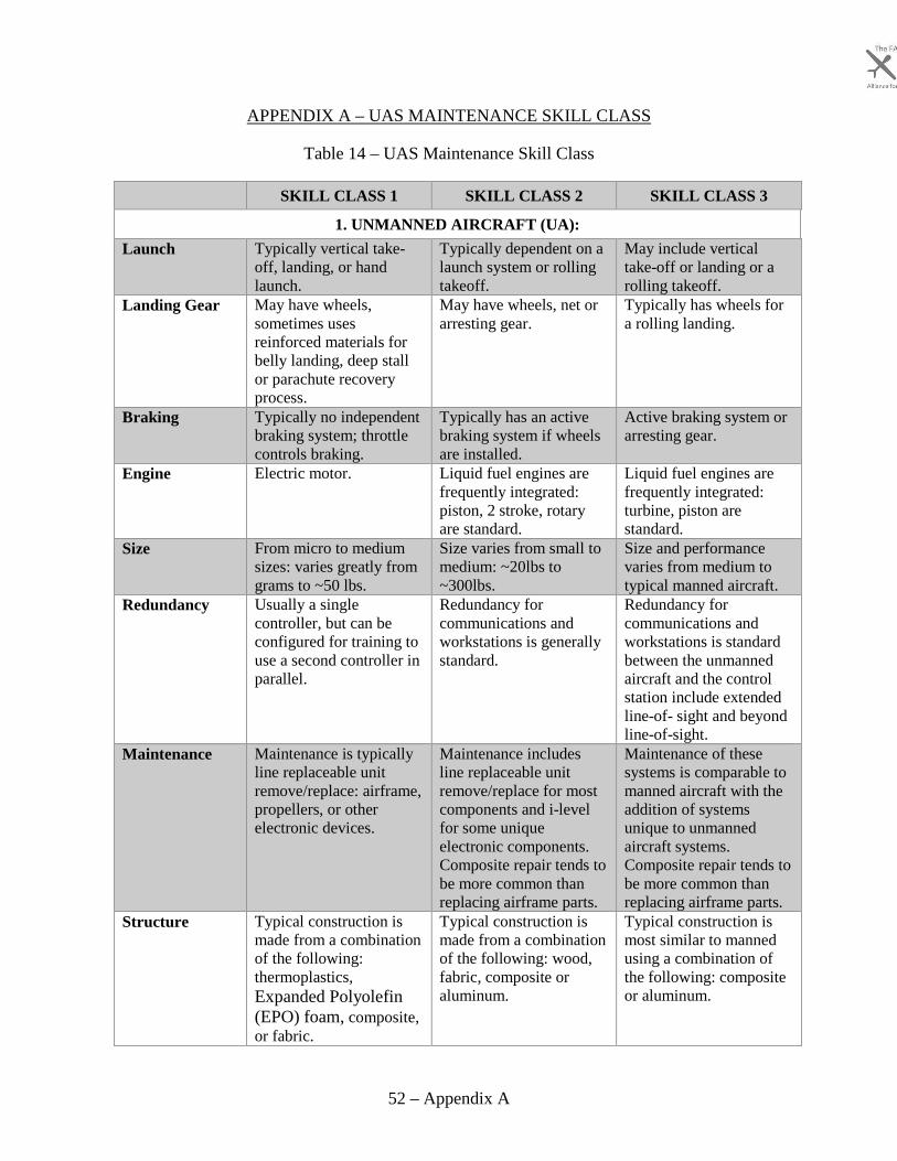
52 – Appendix A
APPENDIX A – UAS MAINTENANCE SKILL CLASS
Table 14 – UAS Maintenance Skill Class
SKILL CLASS 1 SKILL CLASS 2 SKILL CLASS 3
1. UNMANNED AIRCRAFT (UA):Launch Typically vertical take-
off, landing, or hand launch.
Typically dependent on a launch system or rolling takeoff.
May include vertical take-off or landing or a rolling takeoff.
Landing Gear May have wheels, sometimes uses reinforced materials for belly landing, deep stall or parachute recovery process.
May have wheels, net or arresting gear.
Typically has wheels for a rolling landing.
Braking Typically no independent braking system; throttle controls braking.
Typically has an active braking system if wheels are installed.
Active braking system or arresting gear.
Engine Electric motor. Liquid fuel engines are frequently integrated: piston, 2 stroke, rotary are standard.
Liquid fuel engines are frequently integrated: turbine, piston are standard.
Size From micro to medium sizes: varies greatly from grams to ~50 lbs.
Size varies from small to medium: ~20lbs to ~300lbs.
Size and performance varies from medium to typical manned aircraft.
Redundancy Usually a single controller, but can be configured for training to use a second controller in parallel.
Redundancy for communications and workstations is generally standard.
Redundancy for communications and workstations is standard between the unmanned aircraft and the control station include extended line-of- sight and beyond line-of-sight.
Maintenance Maintenance is typically line replaceable unit remove/replace: airframe, propellers, or other electronic devices.
Maintenance includes line replaceable unit remove/replace for most components and i-level for some unique electronic components. Composite repair tends to be more common than replacing airframe parts.
Maintenance of these systems is comparable to manned aircraft with the addition of systems unique to unmanned aircraft systems. Composite repair tends to be more common than replacing airframe parts.
Structure Typical construction is made from a combination of the following: thermoplastics, Expanded Polyolefin (EPO) foam, composite, or fabric.
Typical construction is made from a combination of the following: wood, fabric, composite or aluminum.
Typical construction is most similar to manned using a combination of the following: composite or aluminum.

53 – Appendix A
2. CONTROL STATIONConfiguration Typically, a consumer
electronic device comprised of a single laptop or phone/tablet. Troubleshooting of the control station is usually unnecessary.
Typically a hand portable workstation. Pilots and sensor operators typically have a dedicated workstation and may or may not be dual configurable (redundant).
Typically a fixed or vehicle mounted workstation. Pilots and sensor operators typically have a dedicated workstation and are typically dual configurable (redundant) for multiple pilots, closely resembling the typical cockpit with pilot and copilot sitting beside each other.
Software Software relies on an application to support function, but also has the greatest variability for open systems for larger variation for configuration.
Software is typically a combination of open systems and closed systems for some flight critical items allowing the most variation for configuration.
Software is typically a closed system designed for specific hardware devices, resembling manned aviation's approach for operations.
Networking Little to no networking required.
Computer networking and the use of hubs, switches, or routers is generally necessary.
Computer networking and the use of hubs, switches, or routers is typical.
Maintenance Maintenance is mostly all electronic, typically remove/replace for hardware components and re-install for software.
Maintenance is typically remove/replace for hardware components and re-install for software. Multiple "boxes" with specialty functions may be integrated into the control station: digital video disc player/burner, time code generator, data/communications recording devices, closed caption encoder/decoder, etc.
Maintenance requires computer troubleshooting, line replaceable unit sub-components, and typical aviation manuals.
Communication Links
WEP, WPA or no encryption; visual line of sight link.
Can be a combination of visual line of sight, Radio Line of Sight, or satellite relay. Proprietary encryption is more common.
Communications are typically between the unmanned aircraft and control station include radio line of sight and satellite relay links, and even ground/air relay links. Encryption is standard.

54 – Appendix A
Handover events Atypical, unless training for the vehicle operations.
Complex handover events are frequent, but not standard.
Complex handover events for extended operations are standard.
3. SUPPORT EQUIPMENTLaunch Very little launch support
equipment used, if any. Could be either hand launch or bungee.
A launcher generally assists takeoff. Rolling takeoff may be used. Catapults are pneumatic, hydraulic, spring-loaded, car-top, takeoff cart, or even trebuchet.
Rolling takeoff may be used. Catapults are pneumatic or hydraulic.
Recovery Recovery include airborne capture (net/vertical cable), arresting gear, airbags or parachutes.
Recovery include airborne capture (net/vertical cable), arresting gear, or parachutes.
Recovery include rolling landing, arresting gear, or parachutes.
External Power Not typically used. Typical to external power for pre-flight, starting engines, etc., which are gas powered/building powered ground power unit (GPU).
Engine Support Not typically used. Gas engines use fuel/defuel devises, fuel storage, external power for starting and sometimes a unique device to help start the engine: electric pump, compressed air.
Active sensors Not typically used. Sometimes ground-based radar is used for additional pilot awareness.
Ground based radar and other types of external technology is typically used for additional pilot awareness.
Passive Sensors Sometimes targets are placed around an area for sensors on-board the UA to detect for tracking of information for the payload.
Sometimes targets are placed around an area for sensors on-board the UA to detect for additional pilot awareness and tracking of information for the payload.
Sometimes targets are placed around an area for sensors on-board the UA to detect for additional pilot awareness and tracking of information for the payload.
4. PAYLOADA separate viewing screen may be used for the sensor data but typically, the output is viewable through the software on the computing device.
A separate viewing screen is traditionally used for the sensor data.
Largest payloads for all unmanned aircraft systems. Can include human payloads (e.g. Ehang 184).
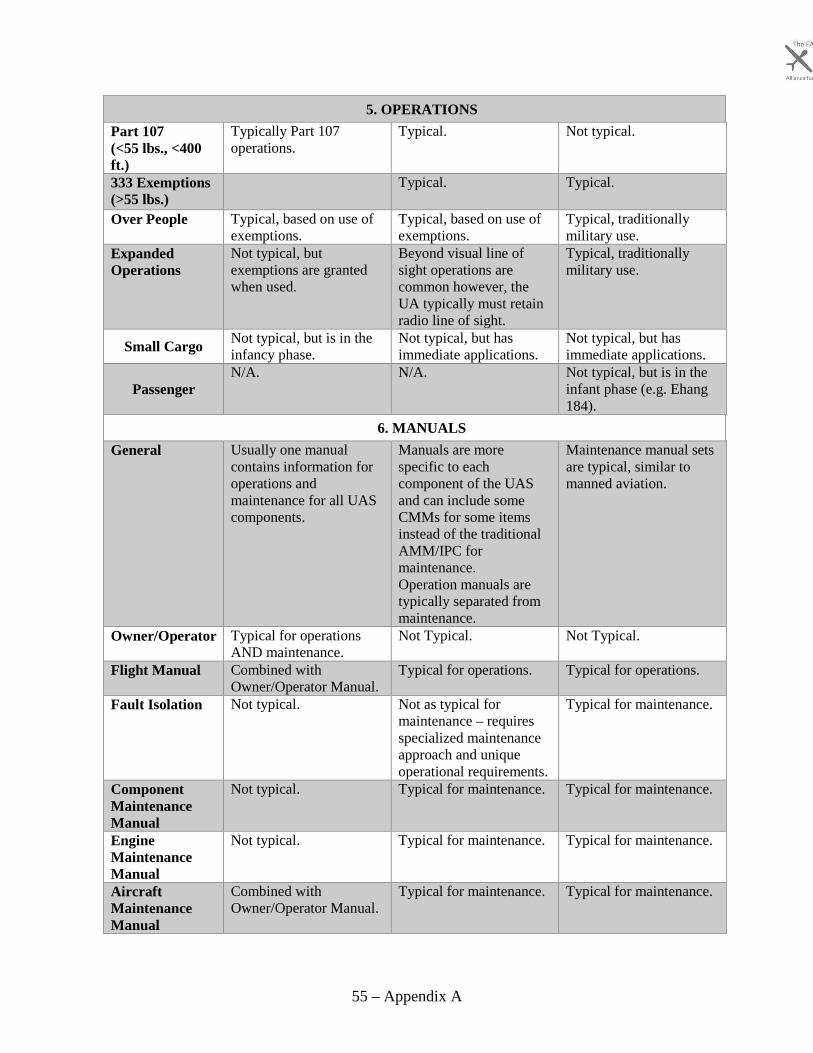
55 – Appendix A
5. OPERATIONSPart 107 (<55 lbs., <400 ft.)
Typically Part 107 operations.
Typical. Not typical.
333 Exemptions (>55 lbs.)
Typical. Typical.
Over People Typical, based on use of exemptions.
Typical, based on use of exemptions.
Typical, traditionally military use.
Expanded Operations
Not typical, but exemptions are granted when used.
Beyond visual line of sight operations are common however, the UA typically must retain radio line of sight.
Typical, traditionally military use.
Small Cargo Not typical, but is in the infancy phase.
Not typical, but has immediate applications.
Not typical, but has immediate applications.
Passenger N/A. N/A. Not typical, but is in the
infant phase (e.g. Ehang 184).
6. MANUALSGeneral Usually one manual
contains information for operations and maintenance for all UAS components.
Manuals are more specific to each component of the UAS and can include some CMMs for some items instead of the traditional AMM/IPC for maintenance. Operation manuals are typically separated from maintenance.
Maintenance manual sets are typical, similar to manned aviation.
Owner/Operator Typical for operations AND maintenance.
Not Typical. Not Typical.
Flight Manual Combined with Owner/Operator Manual.
Typical for operations. Typical for operations.
Fault Isolation Not typical. Not as typical for maintenance – requires specialized maintenance approach and unique operational requirements.
Typical for maintenance.
Component Maintenance Manual
Not typical. Typical for maintenance. Typical for maintenance.
Engine Maintenance Manual
Not typical. Typical for maintenance. Typical for maintenance.
Aircraft Maintenance Manual
Combined with Owner/Operator Manual.
Typical for maintenance. Typical for maintenance.

56 – Appendix A
Illustrated Parts Catalog
Combined with Owner/Operator Manual.
Typical for maintenance. Typical for maintenance.
7. VEHICLE EXAMPLESDJI Phantom, DJI S1000, Yuneec H920, Yuneec Typhoon H, 3DR Aero-M.
Penguin B, MQ-19 Aerosonde, RQ-7 Shadow, Northrop Grumman R-Bat, Bat 12, Bat 14.
RQ-4, MQ-1, MQ-9, K-MAX, Ehang 184, Northrop Grumman Firebird.

57 – Appendix B
APPENDIX B – RECOMMENDED UAS SKILLS
Table 15 – Recommended UAS Skills
UNMANNED AIRCRAFT SYSTEMS SC 1 SC 2 SC 3 Notes
A. UNMANNED AIRCRAFTStructure
Inspect and repair EPO and EPP foam structures.
x Foam as a primary structure is only typical for skill class 1.
Autopilot Inspect, repair, or adjust actuator servo arms and control surface attachment points.
x x x Forms of servo actuators are present in most UAS to move control surfaces.
B. CONTROL STATION (CS)General
Perform control station conformity and safe for flight inspections.
x x x Control stations will be unfamiliar to aviation mechanics.
Inspect, repair, check, service and troubleshoot control station hardware interfaces.
x x x
Inspect, repair, check, troubleshoot and adjust CS ground sensors including GPS and atmospheric sensors.
x x
Microcomputers Inspect, check, service, troubleshoot, and repair microcomputer hardware including peripherals; storage devices, serial connections and printers.
x x x All skill classes of UAS utilize microcomputer systems though some are more complex.
Check, service, troubleshoot, configure and repair microcomputer software including operating system, drivers, applications and interfacing programs including command line interface.
x x x
Perform control system conformity and safe for flight inspections.
x x x
Inspect, check, troubleshoot, and repair video distribution and displays.
x x Skill class 2 and 3 UAS utilize external monitors and video distribution devices to display interfaces and payload feeds.
Check, service, troubleshoot, adjust and repair encryption and password management system.
x x x All skill classes of UAS utilize passwords and encryption to protect information and control station access.
Software Check, service, and troubleshoot the software including software validation, configuration and all updates with post update validations.
x x x Software is common in most control stations though complexity differs among skill classes.

58 – Appendix B
Check, service, troubleshoot and adjust UAS software and firmware compatibility loaded on the autopilot.
x x x
Networking Inspect, repair, troubleshoot, adjust and check microcomputer networks including network addressing schemes, and subnets.
x x x Networks are common in all skill classes of UAS though complexity differs.
Inspect, troubleshoot, repair, check network hardware devices including routers, hubs, bridges, switches and wireless devices.
x x x Networks are common in all skill classes of UAS though the types of devices used differs with skill class.
Check, troubleshoot, and adjust for networks threats.
x x x
Communication Links Antennas, Transmission Lines and Antenna Trackers
Inspect, check, repair, troubleshoot and adjust antenna tracker components.
x x Antenna trackers are only required for long range flights of which skill class 1 is incapable of. Inspect, troubleshoot, service, adjust and
check the antenna tracker system. x x
Radio Monitoring Inspect, check, troubleshoot, adjust and repair spectrum analyzers and radio frequency monitors.
x x Radio monitoring equipment is rarely standard in skill class 1.
Transmitting and Receiving Inspect, check, repair, troubleshoot, service and adjust satellite functions including loopbacks and reach back loops.
x Skill class 3 is the only class to utilize satellite relay links.
Check, troubleshoot, repair and adjust flight communication link integrity.
x x x UAS communication links include software considerations and interdependencies aviation mechanics are unfamiliar.
C. SUPPORT EQUIPMENTLaunchers
Pneumatic and Hydraulic Catapult Launchers Perform catapult launcher conformity and safe for flight inspections.
x x Catapults are not typically used for skill class 1 and are not included in aviation mechanic training. Overhaul catapult launcher. x x
Recovery Net Recovery Systems
Perform recovery conformity and safe for flight inspections.
x Recovery systems are unique to skill class 2 UAS and are unfamiliar to aviation mechanics. Inspect, check, troubleshoot, and repair
the positioning system (typically GPS). x
Inspect, repair, adjust netting. x Overhaul net recovery system. x
Cable Capture Recovery Systems

59 – Appendix B
Perform cable capture conformity and safe for flight inspections.
x Recovery systems are unique to skill class 2 UAS and are unfamiliar to aviation mechanics.
Active Sensors Inspect, repair, check, service, troubleshoot, adjust ground radar.
x
Passive Sensors Inspect, repair, troubleshoot, adjust ground targets.
x x x Passive ground targets will be unfamiliar to aviation mechanics.
A total of 29 UAS recommended skills 15 26 23
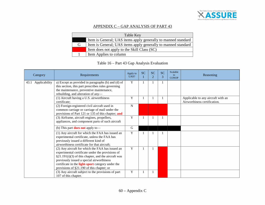
60 – Appendix C
APPENDIX C – GAP ANALYSIS OF PART 43
Table Key Item is General; UAS items apply generally to manned standard
G Item is General; UAS items apply generally to manned standard Item does not apply to the Skill Class (SC) 1 Item Applies to column
Table 16 – Part 43 Gap Analysis Evaluation
Category Requirements Apply to UAS?
SC1
SC2
SC3
Scalable to
CONOP Reasoning
43.1 Applicability a) Except as provided in paragraphs (b) and (d) of this section, this part prescribes rules governing the maintenance, preventive maintenance, rebuilding, and alteration of any—
Y 1 1 1
(1) Aircraft having a U.S. airworthiness certificate;
Y 1 1 1
Applicable to any aircraft with an Airworthiness certification.
(2) Foreign-registered civil aircraft used in common carriage or carriage of mail under the provisions of Part 121 or 135 of this chapter; and
N
(3) Airframe, aircraft engines, propellers, appliances, and component parts of such aircraft
Y 1 1 1
(b) This part does not apply to— G
(1) Any aircraft for which the FAA has issued an experimental certificate, unless the FAA has previously issued a different kind of airworthiness certificate for that aircraft;
Y 1 1 1
(2) Any aircraft for which the FAA has issued an experimental certificate under the provisions of §21.191(i)(3) of this chapter, and the aircraft was previously issued a special airworthiness certificate in the light-sport category under the provisions of §21.190 of this chapter; or
Y 1 1
(3) Any aircraft subject to the provisions of part 107 of this chapter.
Y 1 1
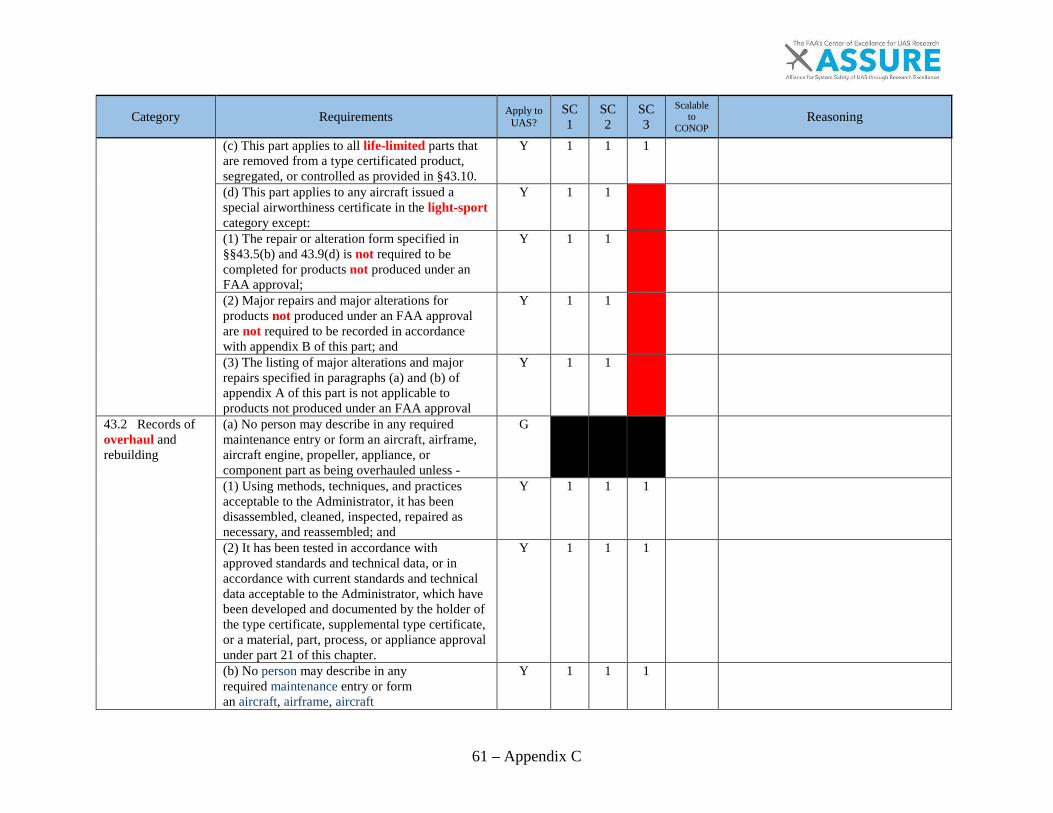
61 – Appendix C
Category Requirements Apply to UAS?
SC1
SC2
SC3
Scalable to
CONOP Reasoning
(c) This part applies to all life-limited parts that are removed from a type certificated product, segregated, or controlled as provided in §43.10.
Y 1 1 1
(d) This part applies to any aircraft issued a special airworthiness certificate in the light-sport category except:
Y 1 1
(1) The repair or alteration form specified in §§43.5(b) and 43.9(d) is not required to be completed for products not produced under an FAA approval;
Y 1 1
(2) Major repairs and major alterations for products not produced under an FAA approval are not required to be recorded in accordance with appendix B of this part; and
Y 1 1
(3) The listing of major alterations and major repairs specified in paragraphs (a) and (b) of appendix A of this part is not applicable to products not produced under an FAA approval
Y 1 1
43.2 Records of overhaul and rebuilding
(a) No person may describe in any required maintenance entry or form an aircraft, airframe, aircraft engine, propeller, appliance, or component part as being overhauled unless -
G
(1) Using methods, techniques, and practices acceptable to the Administrator, it has been disassembled, cleaned, inspected, repaired as necessary, and reassembled; and
Y 1 1 1
(2) It has been tested in accordance with approved standards and technical data, or in accordance with current standards and technical data acceptable to the Administrator, which have been developed and documented by the holder of the type certificate, supplemental type certificate, or a material, part, process, or appliance approval under part 21 of this chapter.
Y 1 1 1
(b) No person may describe in any required maintenance entry or form an aircraft, airframe, aircraft
Y 1 1 1

62 – Appendix C
Category Requirements Apply to UAS?
SC1
SC2
SC3
Scalable to
CONOP Reasoning
engine, propeller,appliance, or component part as being rebuilt unless it has been disassembled, cleaned, inspected, repaired as necessary, reassembled, and tested to the same tolerances and limits as a new item, using either new parts or used parts that either conform to new part tolerances and limits or to approved oversized or undersized dimensions.
43.3 Persons authorized to perform maintenance, preventive maintenance, rebuilding, and alterations.
(a) Except as provided in this section and § 43.17, no person may maintain, rebuild, alter, or perform preventive maintenance on an aircraft, airframe, aircraft engine, propeller, appliance, or component part to which this part applies. Those items, the performance of which is a major alteration, a major repair, or preventive maintenance, are listed in appendix A
N
(b) The holder of a maintenance technician certificate may perform maintenance, preventive maintenance, and alterations as provided in Part 65 of this chapter.
N
(c) The holder of a repairman certificate may perform maintenance, preventive maintenance, and alterations as provided in part 65 of this chapter
N
(d) A person working under the supervision of a holder of a maintenance technician or repairman certificate may perform the maintenance, preventive maintenance, and alterations that his supervisor is authorized to perform, if the supervisor personally observes the work being done to the extent necessary to ensure that it is being done properly and if the supervisor is readily available, in person, for consultation. However, this paragraph does not authorize the performance of any inspection required by Part
N
Maintenance technicians are unqualified to maintain the UAS until UAS considerations are included within Part 147/AC65-2D.
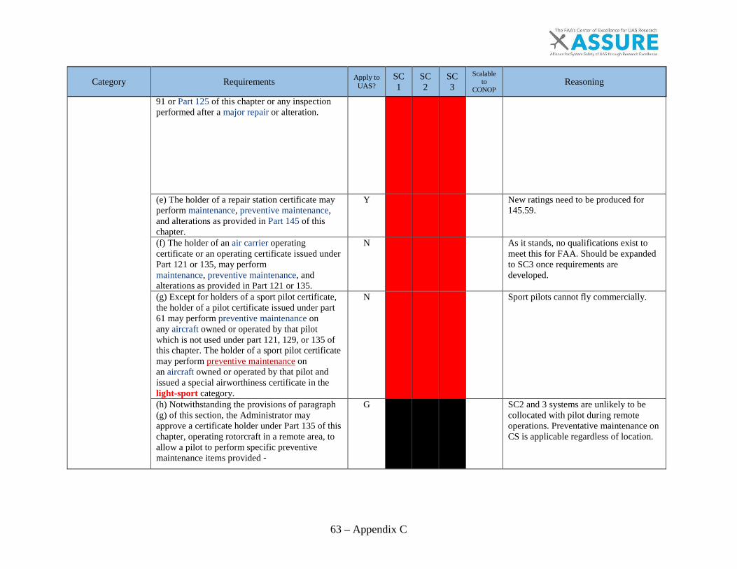
63 – Appendix C
Category Requirements Apply to UAS?
SC1
SC2
SC3
Scalable to
CONOP Reasoning
91 or Part 125 of this chapter or any inspection performed after a major repair or alteration.
(e) The holder of a repair station certificate mayperform maintenance, preventive maintenance,and alterations as provided in Part 145 of thischapter.
Y New ratings need to be produced for 145.59.
(f) The holder of an air carrier operatingcertificate or an operating certificate issued underPart 121 or 135, may performmaintenance, preventive maintenance, andalterations as provided in Part 121 or 135.
N As it stands, no qualifications exist to meet this for FAA. Should be expanded to SC3 once requirements are developed.
(g) Except for holders of a sport pilot certificate,the holder of a pilot certificate issued under part61 may perform preventive maintenance onany aircraft owned or operated by that pilotwhich is not used under part 121, 129, or 135 ofthis chapter. The holder of a sport pilot certificatemay perform preventive maintenance onan aircraft owned or operated by that pilot andissued a special airworthiness certificate in thelight-sport category.
N Sport pilots cannot fly commercially.
(h) Notwithstanding the provisions of paragraph(g) of this section, the Administrator mayapprove a certificate holder under Part 135 of thischapter, operating rotorcraft in a remote area, toallow a pilot to perform specific preventivemaintenance items provided -
G SC2 and 3 systems are unlikely to be collocated with pilot during remote operations. Preventative maintenance on CS is applicable regardless of location.

64 – Appendix C
Category Requirements Apply to UAS?
SC1
SC2
SC3
Scalable to
CONOP Reasoning
(1) The items of preventive maintenance are aresult of a known or suspected maintenancemechanical difficulty or malfunction thatoccurred en route to or in a remote area;
y 1 1 1 Applicable to the system with SC1. Could be applied to the CS for SC2 and SC3. SC2/3 aircraft may not be collocated with pilot.
(2) The pilot has satisfactorily completed anapproved training program and is authorized inwriting by the certificate holder for each item ofpreventive maintenance that the pilot isauthorized to perform;
y 1 1 1 Necessary
(3) There is no certificated maintenancetechnician available to perform preventivemaintenance;
y 1 1 1
(4) The certificate holder has procedures toevaluate the accomplishment of a preventivemaintenance item that requires a decisionconcerning the airworthiness of the rotorcraft;and
y 1 1 1 Necessary
(5) The items of preventive maintenanceauthorized by this section are those listed inparagraph (c) of appendix A of this part.
y 1 1 1 Referenced preventive maintenance should be updated to reflect unmanned aircraft tasks.
(i) Notwithstanding the provisions of paragraph(g) of this section, in accordance with anapproval issued to the holder of a certificateissued under part 135 of this chapter, a pilot of anaircraft type-certificated for 9 or fewer passengerseats, excluding any pilot seat, may perform theremoval and reinstallation of approved aircraftcabin seats, approved cabin-mounted stretchers,and when no tools are required, approved cabin-mounted medical oxygen bottles, provided -
Y 1 Only applicable to SC3 passenger aircraft.
(1) The pilot has satisfactorily completed anapproved training program and is authorized inwriting by the certificate holder to perform eachtask; and
Y 1 Necessary
(2) The certificate holder has written proceduresavailable to the pilot to evaluate theaccomplishment of the task.
Y 1 Necessary

65 – Appendix C
Category Requirements Apply to UAS?
SC1
SC2
SC3
Scalable to
CONOP Reasoning
(j) A manufacturer may - G
(1) Rebuild or alter any aircraft, aircraft engine, propeller, or appliance manufactured by him under a type or production certificate;
Y 1 1 1
(2) Rebuild or alter any appliance or part of aircraft, aircraft engines, propellers, or appliances manufactured by him under a Technical Standard Order Authorization, an FAA-Parts Manufacturer Approval, or Product and Process Specification issued by the Administrator; and
Y
1 1
SC1 parts may need to be FAA approved depending on operational parameters and weight.
(3) Perform any inspection required by part 91 or part 125 of this chapter on aircraft it manufactured under a type certificate, or currently manufactures under a production certificate.
1 1 1
All type certified aircraft should follow applicable regulations. Parts 91 and 125 should be updated to reflect UAS tasks.
k) Updates of databases in installed avionics meeting the conditions of this paragraph are not considered maintenance and may be performed by pilots provided:
Y 1 1 1
For UAS software and firmware for the CS and autopilot are a lot more critical and may require configuration management, and should be considered maintenance. (1) The database upload is: G
(i) Initiated from the flight deck; Y
1 1
(ii) Performed without disassembling the avionics unit; and
Y
1 1
(iii) Performed without the use of tools and/or special equipment.
Y
1 1
(2) The pilot must comply with the certificate holder's procedures or the manufacturer's instructions.
Y 1 1 1
(3) The holder of operating certificates must make available written procedures consistent with manufacturer's instructions to the pilot that describe how to:
Y 1 1 1
(i) Perform the database update; and Y 1 1 1
(ii) Determine the status of the data upload. Y 1 1 1

66 – Appendix C
Category Requirements Apply to UAS?
SC1
SC2
SC3
Scalable to
CONOP Reasoning
43.5 Approval for return to service after maintenance, preventive maintenance, rebuilding, or alteration.
No person may approve for return to service any aircraft, airframe, aircraft engine, propeller, or appliance, that has undergone maintenance, preventive maintenance, rebuilding, or alteration unless -
G
(a) The maintenance record entry required by §43.9 or § 43.11, as appropriate, has been made;
Y 1 1 1
(b) The repair or alteration form authorized by orfurnished by the Administrator has been executedin a manner prescribed by the Administrator; and
Y 1 1 1
(c) If a repair or an alteration results in anychange in the aircraft operating limitations orflight data contained in the approved aircraftflight manual, those operating limitations orflight data are appropriately revised and set forthas prescribed in § 91.9 of this chapter.
N 91.9 would apply if updated for UAS considerations.
43.7 Persons authorized to approve aircraft, airframes, aircraft engines, propellers, appliances, or component parts for return to service after maintenance, preventive maintenance, rebuilding, or alteration.
(a) Except as provided in this section and §43.17, no person, other than the Administrator,may approve an aircraft, airframe, aircraft engine,propeller, appliance, or component part for returnto service after it has undergone maintenance,preventive maintenance, rebuilding, or alteration.
Y 1 1 1
(b) The holder of a maintenance techniciancertificate or an inspection authorization mayapprove an aircraft, airframe, aircraft engine,propeller, appliance, or component part for returnto service as provided in Part 65 of this chapter.
N Would apply once UAS training is implemented but as it stands, they would be unqualified.
(c) The holder of a repair station certificate mayapprove an aircraft, airframe, aircraft engine,propeller, appliance, or component part for returnto service as provided in Part 145 of this chapter.
N Would apply once UAS training is implemented but as it stands, they would be unqualified.
(d) A manufacturer may approve for return toservice any aircraft, airframe, aircraft engine,propeller, appliance, or component part whichthat manufacturer has worked on under § 43.3(j).However, except for minor alterations, the work
N Data not currently approved by administrator.

67 – Appendix C
Category Requirements Apply to UAS?
SC1
SC2
SC3
Scalable to
CONOP Reasoning
must have been done in accordance with technical data approved by the Administrator.
(e) The holder of an air carrier operating certificate or an operating certificate issued under Part 121 or 135, may approve an aircraft, airframe, aircraft engine, propeller, appliance, or component part for return to service as provided in Part 121 or 135 of this chapter, as applicable
N
No additional stipulations for UAS.
(f) A person holding at least a private pilot certificate may approve an aircraft for return to service after performing preventive maintenance under the provisions of § 43.3(g).
N
Private pilots cannot fly commercially.
(g) The holder of a repairman certificate (light-sport aircraft) with a maintenance rating may approve an aircraft issued a special airworthiness certificate in light-sport category for return to service, as provided in part 65 of this chapter.
N
"as provided in part 65" Part 65 repairman requirements are insufficient for UAS as written.
(h) The holder of at least a sport pilot certificate may approve an aircraft owned or operated by that pilot and issued a special airworthiness certificate in the light-sport category for return to service after performing preventive maintenance under the provisions of § 43.3(g).
N
Sport pilots cannot fly commercially.

68 – Appendix C
Category Requirements Apply to UAS?
SC1
SC2
SC3
Scalable to
CONOP Reasoning
43.9 Content, form, and disposition of maintenance, preventive maintenance, rebuilding, and alteration records (except inspections performed in accordance with part 91, part 125, § 135.411(a)(1), and § 135.419 of this chapter).
(a)Maintenance record entries. Except as provided in paragraphs (b) and (c) of this section, each person who maintains, performs preventive maintenance, rebuilds, or alters an aircraft, airframe, aircraft engine, propeller, appliance, or component part shall make an entry in the maintenance record of that equipment containing the following information: (1) A description (or reference to data acceptable to the Administrator) of work performed. (2) The date of completion of the work performed. (3) The name of the person performing the work if other than the person specified in paragraph (a)(4) of this section. (4) If the work performed on the aircraft, airframe, aircraft engine, propeller, appliance, or component part has been performed satisfactorily, the signature, certificate number, and kind of certificate held by the person approving the work. The signature constitutes the approval for return to service only for the work performed.
Y 1 1 1
Maintenance records for ALL SC.
(b) Each holder of an air carrier operating certificate or an operating certificate issued under Part 121 or 135, that is required by its approved operations specifications to provide for a continuous airworthiness maintenance program, shall make a record of the maintenance, preventive maintenance, rebuilding, and alteration, on aircraft, airframes, aircraft engines, propellers, appliances, or component parts which it operates in accordance with the applicable
No additional stipulations for UAS in Part 135.

69 – Appendix C
Category Requirements Apply to UAS?
SC1
SC2
SC3
Scalable to
CONOP Reasoning
provisions of Part 121 or 135 of this chapter, as appropriate. (c) This section does not apply to persons performing inspections in accordance with Part 91, 125, § 135.411(a)(1), or § 135.419 of this chapter.
Y 1 1 1
Maintenance records for ALL SC.
(d) In addition to the entry required by paragraph (a) of this section, major repairs and major alterations shall be entered on a form, and the form disposed of, in the manner prescribed in appendix B, by the person performing the work.
Y
1 1
43.10 Disposition of life-limited aircraft parts.
(a)Definitions used in this section. For the purposes of this section the following definitions apply. Life-limited part means any part for which a mandatory replacement limit is specified in the type design, the Instructions for Continued Airworthiness, or the maintenance manual. Life status means the accumulated cycles, hours, or any other mandatory replacement limit of a life-limited part.
Y 1 1 1
Tracking of life-limited parts for ALL SC.
(b)Temporary removal of parts from type-certificated products. When a life-limited part is temporarily removed and reinstalled for the purpose of performing maintenance, no disposition under paragraph (c) of this section is required if -
Y 1 1 1
Tracking of life-limited parts for ALL SC.
(1) The life status of the part has not changed; Y 1 1 1
Tracking of life-limited parts for ALL SC.
(2) The removal and reinstallation is performed on the same serial numbered product; and
Y 1 1 1
Tracking of life-limited parts for ALL SC.
(3) That product does not accumulate time in service while the part is removed.
Y 1 1 1
Tracking of life-limited parts for ALL SC.

70 – Appendix C
Category Requirements Apply to UAS?
SC1
SC2
SC3
Scalable to
CONOP Reasoning
(c)Disposition of parts removed from type-certificated products. Except as provided in paragraph (b) of this section, after April 15, 2002 each person who removes a life-limited part from a type-certificated product must ensure that the part is controlled using one of the methods in this paragraph. The method must deter the installation of the part after it has reached its life limit. Acceptable methods include:
Y 1 1 1
Tracking of life-limited parts for ALL SC.
(1)Record keeping system. The part may be controlled using a record keeping system that substantiates the part number, serial number, and current life status of the part. Each time the part is removed from a type certificated product, the record must be updated with the current life status. This system may include electronic, paper, or other means of record keeping.
Y 1 1 1
Tracking of life-limited parts for ALL SC.
(2)Tag or record attached to part. A tag or other record may be attached to the part. The tag or record must include the part number, serial number, and current life status of the part. Each time the part is removed from a type certificated product, either a new tag or record must be created, or the existing tag or record must be updated with the current life status.
Y 1 1 1
Tracking of life-limited parts for ALL SC.
(3)Non-permanent marking. The part may be legibly marked using a non-permanent method showing its current life status. The life status must be updated each time the part is removed from a type certificated product, or if the mark is removed, another method in this section may be used. The mark must be accomplished in accordance with the instructions under § 45.16 of this chapter in order to maintain the integrity of the part.
Y 1 1 1
Tracking of life-limited parts for ALL SC.
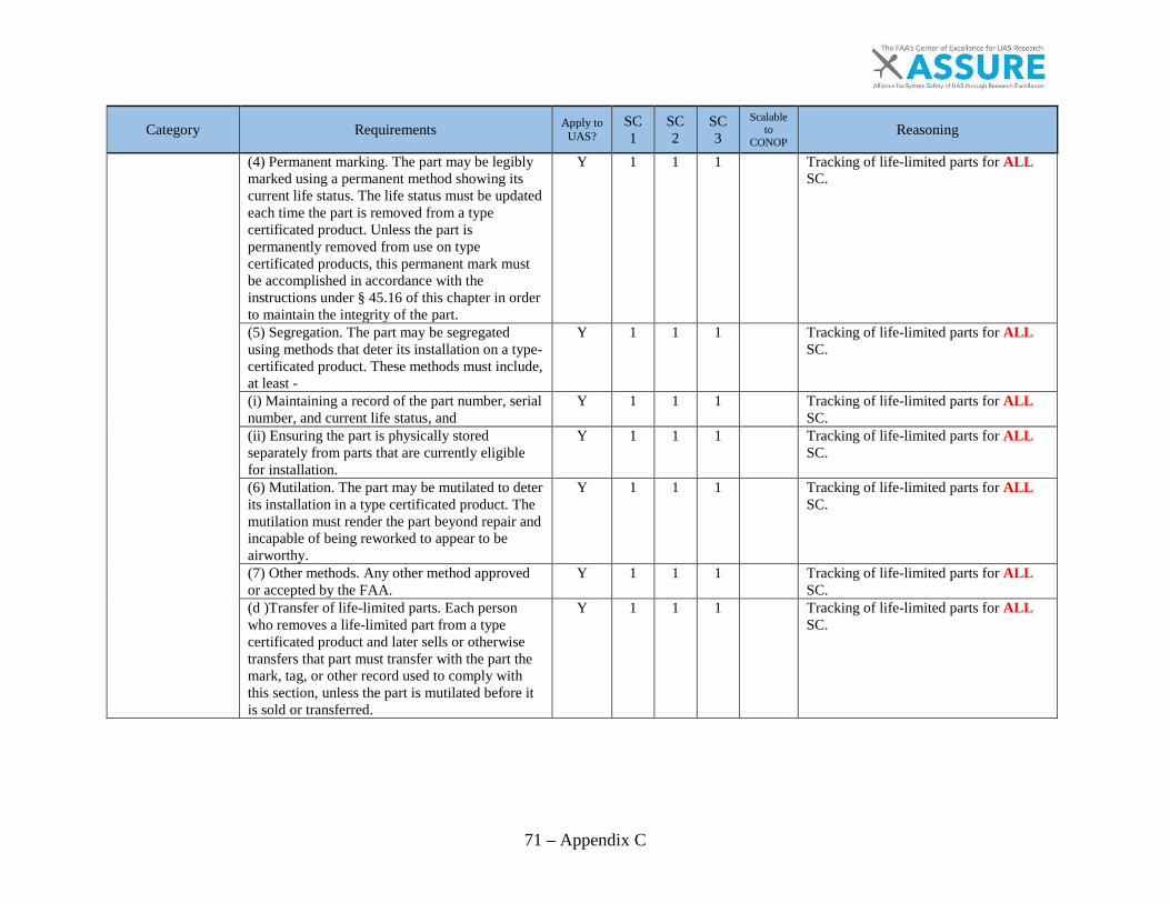
71 – Appendix C
Category Requirements Apply to UAS?
SC1
SC2
SC3
Scalable to
CONOP Reasoning
(4) Permanent marking. The part may be legibly marked using a permanent method showing its current life status. The life status must be updated each time the part is removed from a type certificated product. Unless the part is permanently removed from use on type certificated products, this permanent mark must be accomplished in accordance with the instructions under § 45.16 of this chapter in order to maintain the integrity of the part.
Y 1 1 1
Tracking of life-limited parts for ALL SC.
(5) Segregation. The part may be segregated using methods that deter its installation on a type-certificated product. These methods must include, at least -
Y 1 1 1
Tracking of life-limited parts for ALL SC.
(i) Maintaining a record of the part number, serial number, and current life status, and
Y 1 1 1
Tracking of life-limited parts for ALL SC.
(ii) Ensuring the part is physically stored separately from parts that are currently eligible for installation.
Y 1 1 1
Tracking of life-limited parts for ALL SC.
(6) Mutilation. The part may be mutilated to deter its installation in a type certificated product. The mutilation must render the part beyond repair and incapable of being reworked to appear to be airworthy.
Y 1 1 1
Tracking of life-limited parts for ALL SC.
(7) Other methods. Any other method approved or accepted by the FAA.
Y 1 1 1
Tracking of life-limited parts for ALL SC.
(d )Transfer of life-limited parts. Each person who removes a life-limited part from a type certificated product and later sells or otherwise transfers that part must transfer with the part the mark, tag, or other record used to comply with this section, unless the part is mutilated before it is sold or transferred.
Y 1 1 1
Tracking of life-limited parts for ALL SC.
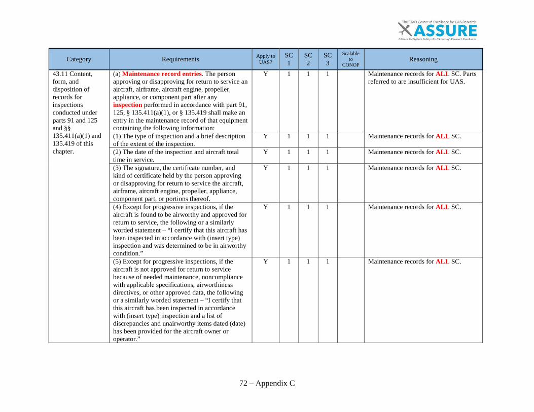
72 – Appendix C
Category Requirements Apply to UAS?
SC1
SC2
SC3
Scalable to
CONOP Reasoning
43.11 Content, form, and disposition of records for inspections conducted under parts 91 and 125 and §§ 135.411(a)(1) and 135.419 of this chapter.
(a) Maintenance record entries. The person approving or disapproving for return to service an aircraft, airframe, aircraft engine, propeller, appliance, or component part after any inspection performed in accordance with part 91, 125, § 135.411(a)(1), or § 135.419 shall make an entry in the maintenance record of that equipment containing the following information:
Y 1 1 1
Maintenance records for ALL SC. Parts referred to are insufficient for UAS.
(1) The type of inspection and a brief description of the extent of the inspection.
Y 1 1 1
Maintenance records for ALL SC.
(2) The date of the inspection and aircraft total time in service.
Y 1 1 1
Maintenance records for ALL SC.
(3) The signature, the certificate number, and kind of certificate held by the person approving or disapproving for return to service the aircraft, airframe, aircraft engine, propeller, appliance, component part, or portions thereof.
Y 1 1 1
Maintenance records for ALL SC.
(4) Except for progressive inspections, if the aircraft is found to be airworthy and approved for return to service, the following or a similarly worded statement – “I certify that this aircraft has been inspected in accordance with (insert type) inspection and was determined to be in airworthy condition.”
Y 1 1 1
Maintenance records for ALL SC.
(5) Except for progressive inspections, if the aircraft is not approved for return to service because of needed maintenance, noncompliance with applicable specifications, airworthiness directives, or other approved data, the following or a similarly worded statement – “I certify that this aircraft has been inspected in accordance with (insert type) inspection and a list of discrepancies and unairworthy items dated (date) has been provided for the aircraft owner or operator.”
Y 1 1 1
Maintenance records for ALL SC.

73 – Appendix C
Category Requirements Apply to UAS?
SC1
SC2
SC3
Scalable to
CONOP Reasoning
(6) For progressive inspections, the following or a similarly worded statement – “I certify that in accordance with a progressive inspection program, a routine inspection of (identify whether aircraft or components) and a detailed inspection of (identify components) were performed and the (aircraft or components) are (approved or disapproved) for return to service.” If disapproved, the entry will further state “and a list of discrepancies and unairworthy items dated (date) has been provided to the aircraft owner or operator.
Y
1
(7) If an inspection is conducted under an inspection program provided for in part 91, 125, or § 135.411(a)(1), the entry must identify the inspection program, that part of the inspection program accomplished, and contain a statement that the inspection was performed in accordance with the inspections and procedures for that particular program.
Y 1 1 1
Maintenance records for ALL SC.
(b) Listing of discrepancies and placards. If the person performing any inspection required by part 91 or 125 or § 135.411(a)(1) of this chapter finds that the aircraft is unairworthy or does not meet the applicable type certificate data, airworthiness directives, or other approved data upon which its airworthiness depends, that persons must give the owner or lessee a signed and dated list of those discrepancies. For those items permitted to be inoperative under § 91.213(d)(2) of this chapter, that person shall place a placard, that meets the aircraft's airworthiness certification regulations, on each inoperative instrument and the cockpit control of each item of inoperative equipment, marking it “Inoperative,” and shall add the items to the
Y 1 1 1
Maintenance records for ALL SC.
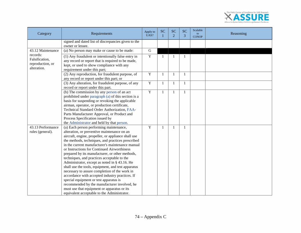
74 – Appendix C
Category Requirements Apply to UAS?
SC1
SC2
SC3
Scalable to
CONOP Reasoning
signed and dated list of discrepancies given to the owner or lessee.
43.12 Maintenance records: Falsification, reproduction, or alteration.
(a) No person may make or cause to be made: G
(1) Any fraudulent or intentionally false entry in any record or report that is required to be made, kept, or used to show compliance with any requirement under this part;
Y 1 1 1
(2) Any reproduction, for fraudulent purpose, of any record or report under this part; or
Y 1 1 1
(3) Any alteration, for fraudulent purpose, of any record or report under this part.
Y 1 1 1
(b) The commission by any person of an act prohibited under paragraph (a) of this section is a basis for suspending or revoking the applicable airman, operator, or production certificate, Technical Standard Order Authorization, FAA-Parts Manufacturer Approval, or Product and Process Specification issued by the Administrator and held by that person.
Y 1 1 1
43.13 Performance rules (general).
(a) Each person performing maintenance, alteration, or preventive maintenance on an aircraft, engine, propeller, or appliance shall use the methods, techniques, and practices prescribed in the current manufacturer's maintenance manual or Instructions for Continued Airworthiness prepared by its manufacturer, or other methods, techniques, and practices acceptable to the Administrator, except as noted in § 43.16. He shall use the tools, equipment, and test apparatus necessary to assure completion of the work in accordance with accepted industry practices. If special equipment or test apparatus is recommended by the manufacturer involved, he must use that equipment or apparatus or its equivalent acceptable to the Administrator.
Y 1 1 1

75 – Appendix C
Category Requirements Apply to UAS?
SC1
SC2
SC3
Scalable to
CONOP Reasoning
(b) Each person maintaining or altering, or performing preventive maintenance, shall do that work in such a manner and use materials of such a quality, that the condition of the aircraft, airframe, aircraft engine, propeller, or appliance worked on will be at least equal to its original or properly altered condition (with regard to aerodynamic function, structural strength, resistance to vibration and deterioration, and other qualities affecting airworthiness).
Y 1 1 1
(c)Special provisions for holders of air carrier operating certificates and operating certificates issued under the provisions of Part 121 or 135 and Part 129 operators holding operations specifications. Unless otherwise notified by the administrator, the methods, techniques, and practices contained in the maintenance manual or the maintenance part of the manual of the holder of an air carrier operating certificate or an operating certificate under Part 121 or 135 and Part 129 operators holding operations specifications (that is required by its operating specifications to provide a continuous airworthiness maintenance and inspection program) constitute acceptable means of compliance with this section.
Parts are insufficient for UAS.
43.15 Additional performance rules for inspections.
(a)General. Each person performing an inspection required by part 91, 125, or 135 of this chapter, shall -
G
(1) Perform the inspection so as to determine whether the aircraft, or portion(s) thereof under inspection, meets all applicable airworthiness requirements; and
Y 1 1 1
(2) If the inspection is one provided for in part 125, 135, or § 91.409(e) of this chapter, perform the inspection in accordance with the instructions
Y
1 1
Parts are insufficient for UAS.

76 – Appendix C
Category Requirements Apply to UAS?
SC1
SC2
SC3
Scalable to
CONOP Reasoning
and procedures set forth in the inspection program for the aircraft being inspected. (b)Rotorcraft. Each person performing an inspection required by Part 91 on a rotorcraft shall inspect the following systems in accordance with the maintenance manual or Instructions for Continued Airworthiness of the manufacturer concerned:
Y
1 1
Parts are insufficient for UAS.
(1) The drive shafts or similar systems. Y 1 1 1
(2) The main rotor transmission gear box for obvious defects.
Y 1 1 1
(3) The main rotor and center section (or the equivalent area).
Y 1 1 1
(4) The auxiliary rotor on helicopters. Y 1 1 1
(c)Annual and 100-hour inspections. Y 1 1 1
Requirements may be different between skill classes.
(1) Each person performing an annual or 100-hour inspection shall use a checklist while performing the inspection. The checklist may be of the person's own design, one provided by the manufacturer of the equipment being inspected or one obtained from another source. This checklist must include the scope and detail of the items contained in appendix D to this part and paragraph (b) of this section.
Y 1 1 1
Yes use checklist but Appendix D does not fully apply to UAS as written.
(2) Each person approving a reciprocating-engine-powered aircraft for return to service after an annual or 100-hour inspection shall, before that approval, run the aircraft engine or engines to determine satisfactory performance in accordance with the manufacturer's recommendations of -
Y 1 1 1
(i) Power output (static and idle r.p.m.); Y 1 1 1
(ii) Magnetos; Y
1 1
(iii) Fuel and oil pressure; and Y
1 1

77 – Appendix C
Category Requirements Apply to UAS?
SC1
SC2
SC3
Scalable to
CONOP Reasoning
(iv) Cylinder and oil temperature. Y
1 1
(3) Each person approving a turbine-engine-powered aircraft for return to service after an annual, 100-hour, or progressive inspection shall, before that approval, run the aircraft engine or engines to determine satisfactory performance in accordance with the manufacturer's recommendations.
Y
1
d) Progressive inspection. G
(1) Each person performing a progressive inspection shall, at the start of a progressive inspection system, inspect the aircraft completely. After this initial inspection, routine and detailed inspections must be conducted as prescribed in the progressive inspection schedule. Routine inspections consist of visual examination or check of the appliances, the aircraft, and its components and systems, insofar as practicable without disassembly. Detailed inspections consist of a thorough examination of the appliances, the aircraft, and its components and systems, with such disassembly as is necessary. For the purposes of this subparagraph, the overhaul of a component or system is considered to be a detailed inspection.
Y
1
Progressive inspections are unnecessary on SC1/2 systems.
(2) If the aircraft is away from the station where inspections are normally conducted, an appropriately rated maintenance technician, a certificated repair station, or the manufacturer of the aircraft may perform inspections in accordance with the procedures and using the forms of the person who would otherwise perform the inspection.
Y 1 1 1

78 – Appendix C
Category Requirements Apply to UAS?
SC1
SC2
SC3
Scalable to
CONOP Reasoning
43.16 Airworthiness limitations.
Each person performing an inspection or other maintenance specified in an Airworthiness Limitations section of a manufacturer's maintenance manual or Instructions for Continued Airworthiness shall perform the inspection or other maintenance in accordance with that section, or in accordance with operations specifications approved by the Administrator under part 121 or 135, or an inspection program approved under § 91.409(e).
Y 1 1 1
43.17 Maintenance, preventive maintenance, and alterations performed on U.S. aeronautical products by certain Canadian persons.
(a)Definitions. For purposes of this section: Aeronautical product means any civil aircraft or airframe, aircraft engine, propeller, appliance, component, or part to be installed thereon. Canadian aeronautical product means any aeronautical product under airworthiness regulation by Transport Canada Civil Aviation. U.S. aeronautical product means any aeronautical product under airworthiness regulation by the FAA.
N
For the purpose of this report, it has been determined that if the CAA meets future FAA UAS requirements, these could apply but do not currently apply.
(b) Applicability. This section does not apply to any U.S. aeronautical products maintained or altered under any bilateral agreement made between Canada and any country other than the United States.
N
(c) Authorized persons. N
(1) A person holding a valid Transport Canada Civil Aviation Maintenance Engineer license and appropriate ratings may, with respect to a U.S.-registered aircraft located in Canada, perform maintenance, preventive maintenance, and alterations in accordance with the requirements of paragraph (d) of this section and approve the affected aircraft for return to service in
N
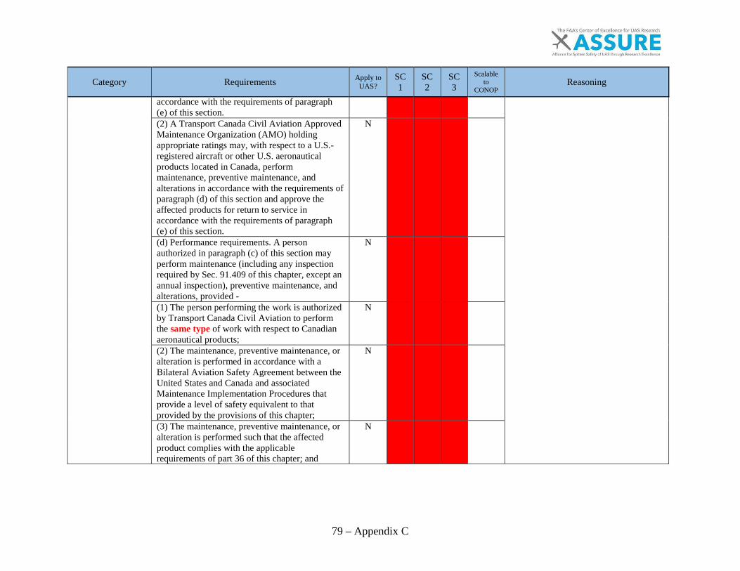
79 – Appendix C
Category Requirements Apply to UAS?
SC1
SC2
SC3
Scalable to
CONOP Reasoning
accordance with the requirements of paragraph (e) of this section. (2) A Transport Canada Civil Aviation Approved Maintenance Organization (AMO) holding appropriate ratings may, with respect to a U.S.-registered aircraft or other U.S. aeronautical products located in Canada, perform maintenance, preventive maintenance, and alterations in accordance with the requirements of paragraph (d) of this section and approve the affected products for return to service in accordance with the requirements of paragraph (e) of this section.
N
(d) Performance requirements. A person authorized in paragraph (c) of this section may perform maintenance (including any inspection required by Sec. 91.409 of this chapter, except an annual inspection), preventive maintenance, and alterations, provided -
N
(1) The person performing the work is authorized by Transport Canada Civil Aviation to perform the same type of work with respect to Canadian aeronautical products;
N
(2) The maintenance, preventive maintenance, or alteration is performed in accordance with a Bilateral Aviation Safety Agreement between the United States and Canada and associated Maintenance Implementation Procedures that provide a level of safety equivalent to that provided by the provisions of this chapter;
N
(3) The maintenance, preventive maintenance, or alteration is performed such that the affected product complies with the applicable requirements of part 36 of this chapter; and
N
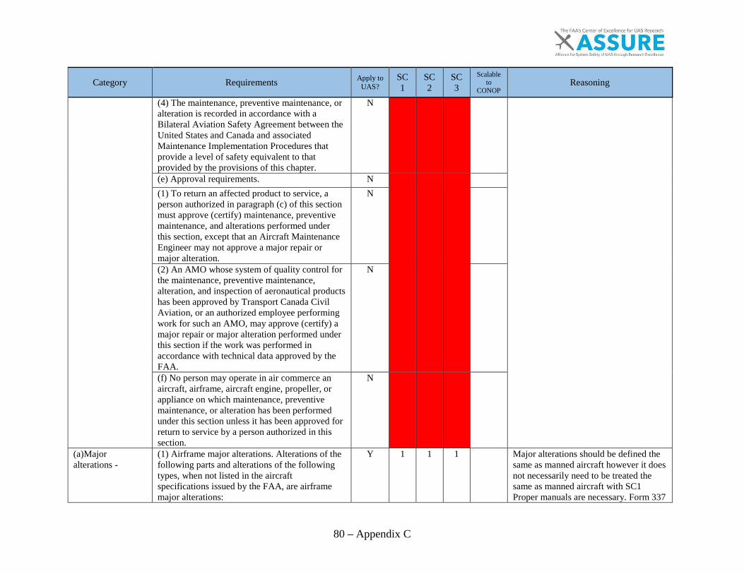
80 – Appendix C
Category Requirements Apply to UAS?
SC1
SC2
SC3
Scalable to
CONOP Reasoning
(4) The maintenance, preventive maintenance, or alteration is recorded in accordance with a Bilateral Aviation Safety Agreement between the United States and Canada and associated Maintenance Implementation Procedures that provide a level of safety equivalent to that provided by the provisions of this chapter.
N
(e) Approval requirements. N
(1) To return an affected product to service, a person authorized in paragraph (c) of this section must approve (certify) maintenance, preventive maintenance, and alterations performed under this section, except that an Aircraft Maintenance Engineer may not approve a major repair or major alteration.
N
(2) An AMO whose system of quality control for the maintenance, preventive maintenance, alteration, and inspection of aeronautical products has been approved by Transport Canada Civil Aviation, or an authorized employee performing work for such an AMO, may approve (certify) a major repair or major alteration performed under this section if the work was performed in accordance with technical data approved by the FAA.
N
(f) No person may operate in air commerce an aircraft, airframe, aircraft engine, propeller, or appliance on which maintenance, preventive maintenance, or alteration has been performed under this section unless it has been approved for return to service by a person authorized in this section.
N
(a)Major alterations -
(1) Airframe major alterations. Alterations of the following parts and alterations of the following types, when not listed in the aircraft specifications issued by the FAA, are airframe major alterations:
Y 1 1 1
Major alterations should be defined the same as manned aircraft however it does not necessarily need to be treated the same as manned aircraft with SC1 Proper manuals are necessary. Form 337
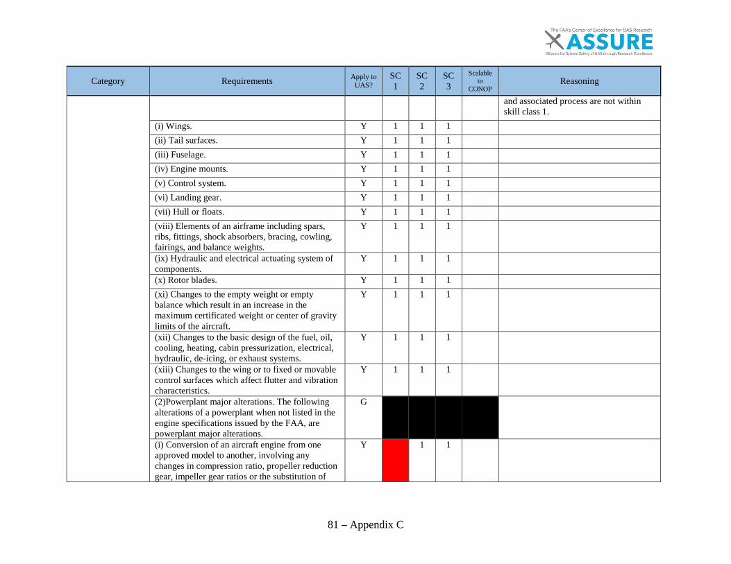
81 – Appendix C
Category Requirements Apply to UAS?
SC1
SC2
SC3
Scalable to
CONOP Reasoning
and associated process are not within skill class 1.
(i) Wings. Y 1 1 1
(ii) Tail surfaces. Y 1 1 1
(iii) Fuselage. Y 1 1 1
(iv) Engine mounts. Y 1 1 1
(v) Control system. Y 1 1 1
(vi) Landing gear. Y 1 1 1
(vii) Hull or floats. Y 1 1 1
(viii) Elements of an airframe including spars, ribs, fittings, shock absorbers, bracing, cowling, fairings, and balance weights.
Y 1 1 1
(ix) Hydraulic and electrical actuating system of components.
Y 1 1 1
(x) Rotor blades. Y 1 1 1
(xi) Changes to the empty weight or empty balance which result in an increase in the maximum certificated weight or center of gravity limits of the aircraft.
Y 1 1 1
(xii) Changes to the basic design of the fuel, oil, cooling, heating, cabin pressurization, electrical, hydraulic, de-icing, or exhaust systems.
Y 1 1 1
(xiii) Changes to the wing or to fixed or movable control surfaces which affect flutter and vibration characteristics.
Y 1 1 1
(2)Powerplant major alterations. The following alterations of a powerplant when not listed in the engine specifications issued by the FAA, are powerplant major alterations.
G
(i) Conversion of an aircraft engine from one approved model to another, involving any changes in compression ratio, propeller reduction gear, impeller gear ratios or the substitution of
Y
1 1

82 – Appendix C
Category Requirements Apply to UAS?
SC1
SC2
SC3
Scalable to
CONOP Reasoning
major engine parts which requires extensive rework and testing of the engine. (ii) Changes to the engine by replacing aircraft engine structural parts with parts not supplied by the original manufacturer or parts not specifically approved by the Administrator.
Y
1 1
(iii) Installation of an accessory which is not approved for the engine.
Y
1 1
(iv) Removal of accessories that are listed as required equipment on the aircraft or engine specification.
Y
1 1
(v) Installation of structural parts other than the type of parts approved for the installation.
Y
1 1
(vi) Conversions of any sort for the purpose of using fuel of a rating or grade other than that listed in the engine specifications.
Y
1 1
(3) Propeller major alterations. The following alterations of a propeller when not authorized in the propeller specifications issued by the FAA are propeller major alterations:
Y
1 1
SC2 do not currently go through major prop alterations often however when done, should be treated as a major alteration. Because of SC2 operations being closer to SC3 it makes sense to still allow for major prop alterations.
(i) Changes in blade design. Y
1 1
(ii) Changes in hub design. Y
1 1
(iii) Changes in the governor or control design. Y
1 1
(iv) Installation of a propeller governor or feathering system.
Y
1 1
(v) Installation of propeller de-icing system. Y
1 1
(vi) Installation of parts not approved for the propeller.
Y
1 1
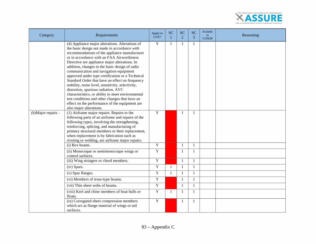
83 – Appendix C
Category Requirements Apply to UAS?
SC1
SC2
SC3
Scalable to
CONOP Reasoning
(4) Appliance major alterations. Alterations of the basic design not made in accordance with recommendations of the appliance manufacturer or in accordance with an FAA Airworthiness Directive are appliance major alterations. In addition, changes in the basic design of radio communication and navigation equipment approved under type certification or a Technical Standard Order that have an effect on frequency stability, noise level, sensitivity, selectivity, distortion, spurious radiation, AVC characteristics, or ability to meet environmental test conditions and other changes that have an effect on the performance of the equipment are also major alterations.
Y 1 1 1
(b)Major repairs - (1) Airframe major repairs. Repairs to the following parts of an airframe and repairs of the following types, involving the strengthening, reinforcing, splicing, and manufacturing of primary structural members or their replacement, when replacement is by fabrication such as riveting or welding, are airframe major repairs.
Y
1 1
(i) Box beams. Y
1 1
(ii) Monocoque or semimonocoque wings or control surfaces.
Y
1 1
(iii) Wing stringers or chord members. Y
1 1
(iv) Spars. Y 1 1 1
(v) Spar flanges. Y 1 1 1
(vi) Members of truss-type beams. Y
1 1
(vii) Thin sheet webs of beams. Y
1 1
(viii) Keel and chine members of boat hulls or floats.
Y 1 1 1
(ix) Corrugated sheet compression members which act as flange material of wings or tail surfaces.
Y
1 1
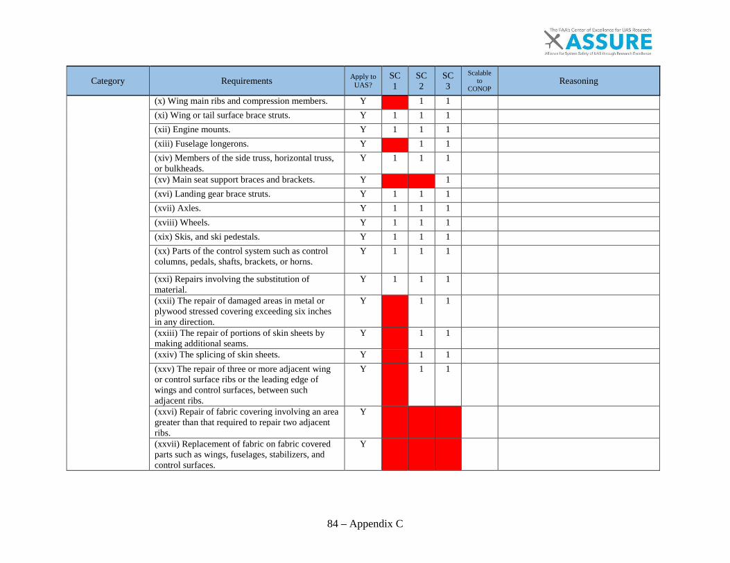
84 – Appendix C
Category Requirements Apply to UAS?
SC1
SC2
SC3
Scalable to
CONOP Reasoning
(x) Wing main ribs and compression members. Y
1 1
(xi) Wing or tail surface brace struts. Y 1 1 1
(xii) Engine mounts. Y 1 1 1
(xiii) Fuselage longerons. Y
1 1
(xiv) Members of the side truss, horizontal truss, or bulkheads.
Y 1 1 1
(xv) Main seat support braces and brackets. Y
1
(xvi) Landing gear brace struts. Y 1 1 1
(xvii) Axles. Y 1 1 1
(xviii) Wheels. Y 1 1 1
(xix) Skis, and ski pedestals. Y 1 1 1
(xx) Parts of the control system such as control columns, pedals, shafts, brackets, or horns.
Y 1 1 1
(xxi) Repairs involving the substitution of material.
Y 1 1 1
(xxii) The repair of damaged areas in metal or plywood stressed covering exceeding six inches in any direction.
Y
1 1
(xxiii) The repair of portions of skin sheets by making additional seams.
Y
1 1
(xxiv) The splicing of skin sheets. Y
1 1
(xxv) The repair of three or more adjacent wing or control surface ribs or the leading edge of wings and control surfaces, between such adjacent ribs.
Y
1 1
(xxvi) Repair of fabric covering involving an area greater than that required to repair two adjacent ribs.
Y
(xxvii) Replacement of fabric on fabric covered parts such as wings, fuselages, stabilizers, and control surfaces.
Y

85 – Appendix C
Category Requirements Apply to UAS?
SC1
SC2
SC3
Scalable to
CONOP Reasoning
(xxviii) Repairing, including rebottoming, ofremovable or integral fuel tanks and oil tanks.
Y 1 1
(2) Powerplant major repairs. Repairs of thefollowing parts of an engine and repairs of thefollowing types, are powerplant major repairs:
G
(i) Separation or disassembly of a crankcase orcrankshaft of a reciprocating engine equippedwith an integral supercharger.
Y 1 1 Not typically for SC2 but applicable where equipped.
(ii) Separation or disassembly of a crankcase orcrankshaft of a reciprocating engine equippedwith other than spur-type propeller reductiongearing.
Y 1 1 Not typically for SC2 but applicable where equipped.
(iii) Special repairs to structural engine parts bywelding, plating, metalizing, or other methods.
Y 1 1
(3)Propeller major repairs. Repairs of thefollowing types to a propeller are propeller majorrepairs:
G
(i) Any repairs to, or straightening of steel blades. Y 1 1 Not typically for SC2 but applicable where equipped.
(ii) Repairing or machining of steel hubs. Y 1 1 Not typically for SC2 but applicable where equipped.
(iii) Shortening of blades. Y 1 1 Not typically for SC2 but applicable where equipped.
(iv) Retipping of wood propellers. Y 1 1 Not typically for SC2 but applicable where equipped.
(v) Replacement of outer laminations on fixedpitch wood propellers.
Y 1 1 Not typically for SC2 but applicable where equipped.
(vi) Repairing elongated bolt holes in the hub offixed pitch wood propellers.
Y 1 1 Not typically for SC2 but applicable where equipped.
(vii) Inlay work on wood blades. Y 1 1 Not typically for SC2 but applicable where equipped.
(viii) Repairs to composition blades. Y 1 1 Not typically for SC2 but applicable where equipped.
(ix) Replacement of tip fabric. Y 1 1 Not typically for SC2 but applicable where equipped.

86 – Appendix C
Category Requirements Apply to UAS?
SC1
SC2
SC3
Scalable to
CONOP Reasoning
(x) Replacement of plastic covering. Y
1 1
Not typically for SC2 but applicable where equipped.
(xi) Repair of propeller governors. Y
1 1
Not typically for SC2 but applicable where equipped.
(xii) Overhaul of controllable pitch propellers. Y
1 1
Not typically for SC2 but applicable where equipped.
(xiii) Repairs to deep dents, cuts, scars, nicks, etc., and straightening of aluminum blades.
Y
1 1
Not typically for SC2 but applicable where equipped.
(xiv) The repair or replacement of internal elements of blades.
Y
1 1
Not typically for SC2 but applicable where equipped.
4) Appliance major repairs. Repairs of the following types to appliances are appliance major repairs:
G
(i) Calibration and repair of instruments. Y 1 1 1
SC1 – Calibration of these components, while critical, are operator level tasks. Instruments are not repairable and are a function of software and a flight control board.
(ii) Calibration of radio equipment. Y 1 1 1
(iii) Rewinding the field coil of an electrical accessory.
Y
1 1
(iv) Complete disassembly of complex hydraulic power valves.
Y
1 1
(v) Overhaul of pressure type carburetors, and pressure type fuel, oil and hydraulic pumps.
Y
1 1
(c)Preventive maintenance. Preventive maintenance is limited to the following work, provided it does not involve complex assembly operations:
(1) Removal, installation, and repair of landing gear tires.
Y 1 1 1
(2) Replacing elastic shock absorber cords on landing gear.
Y
1 1
(3) Servicing landing gear shock struts by adding oil, air, or both.
Y
1 1
(4) Servicing landing gear wheel bearings, such as cleaning and greasing.
Y
1 1
(5) Replacing defective safety wiring or cotter keys.
Y
1 1
(6) Lubrication not requiring disassembly other than removal of nonstructural items such as cover plates, cowlings, and fairings.
Y
1 1

87 – Appendix C
Category Requirements Apply to UAS?
SC1
SC2
SC3
Scalable to
CONOP Reasoning
(7) Making simple fabric patches not requiring rib stitching or the removal of structural parts or control surfaces. In the case of balloons, the making of small fabric repairs to envelopes (as defined in, and in accordance with, the balloon manufacturers' instructions) not requiring load tape repair or replacement.
Y
(8) Replenishing hydraulic fluid in the hydraulic reservoir
Y
1 1
(9) Refinishing decorative coating of fuselage Y 1 1 1
Non typical with SC1. 10) Applying preservative or protective material to components where no disassembly of any primary structure or operating system is involved and where such coating is not prohibited or is not contrary to good practices.
Y
1 1
(11) Repairing upholstery and decorative furnishings of the cabin, cockpit, or balloon basket interior when the repairing does not require disassembly of any primary structure or operating system or interfere with an operating system or affect the primary structure of the aircraft.
Y
1
(12) Making small simple repairs to fairings, nonstructural cover plates, cowlings, and small patches and reinforcements not changing the contour so as to interfere with proper air flow.
Y 1 1 1
(13) Replacing side windows where that work does not interfere with the structure or any operating system such as controls, electrical equipment, etc.
Y
1
Payload specific (passengers).
(14) Replacing safety belts Y
1
(15) Replacing seats or seat parts with replacement parts approved for the aircraft, not involving disassembly of any primary structure or operating system
Y
1

88 – Appendix C
Category Requirements Apply to UAS?
SC1
SC2
SC3
Scalable to
CONOP Reasoning
16) Trouble shooting and repairing broken circuits in landing light wiring circuits.
Y 1 1 1
(17) Replacing bulbs., reflectors, and lenses of position and landing lights.
Y 1 1 1
(18) Replacing wheels and skis where no weight and balance computation is involved.
Y 1 1 1
(19) Replacing any cowling not requiring removal of the propeller or disconnection of flight controls.
Y 1 1 1
(20) Replacing or cleaning spark plugs and setting of spark plug gap clearance.
Y
1 1
(21) Replacing any hose connection except hydraulic connections.
Y 1 1 1
(22) Replacing prefabricated fuel lines. Y
1 1
(23) Cleaning or replacing fuel and oil strainers or filter elements.
Y
1 1
(24) Replacing and servicing batteries. Y 1 1 1
SC1 multipurpose use for fuel and power. Batteries used in GPS or other systems (CMOS).
(25) Cleaning of balloon burner pilot and main nozzles in accordance with the balloon manufacturer's instructions.
Y
(26) Replacement or adjustment of nonstructural standard fasteners incidental to operations.
Y 1 1 1
(27) The interchange of balloon baskets and burners on envelopes when the basket or burner is designated as interchangeable in the balloon type certificate data and the baskets and burners are specifically designed for quick removal and installation.
N
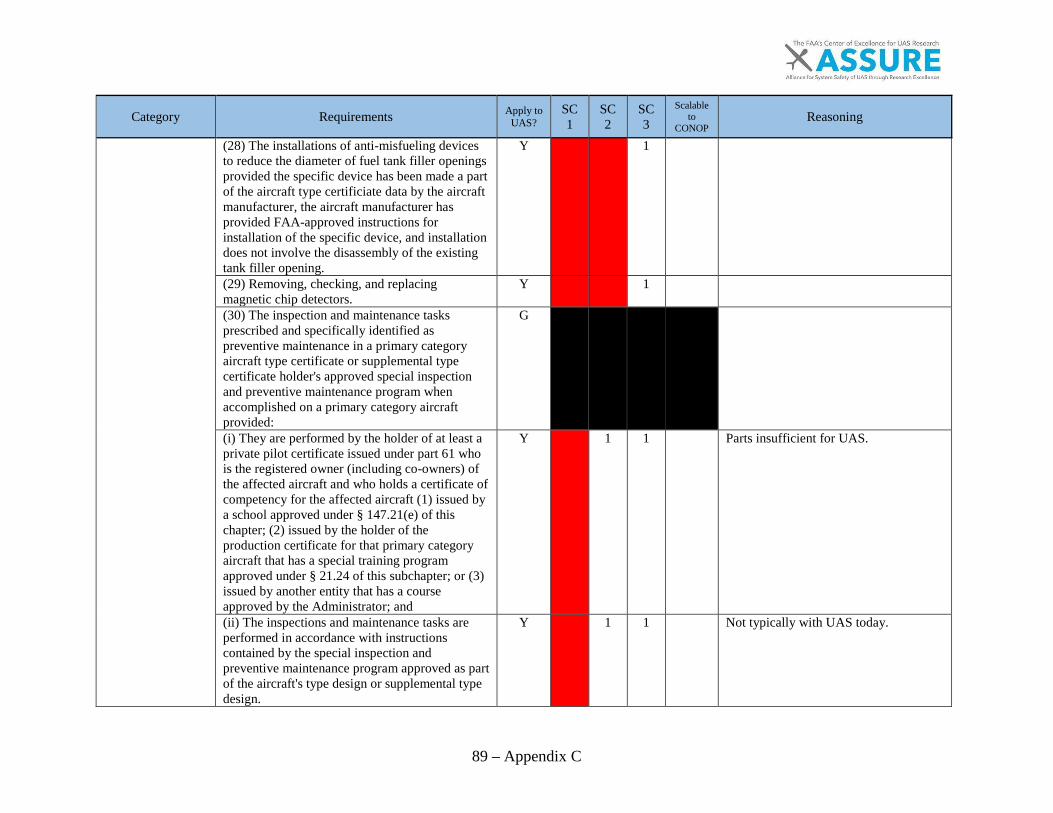
89 – Appendix C
Category Requirements Apply to UAS?
SC1
SC2
SC3
Scalable to
CONOP Reasoning
(28) The installations of anti-misfueling devices to reduce the diameter of fuel tank filler openings provided the specific device has been made a part of the aircraft type certificiate data by the aircraft manufacturer, the aircraft manufacturer has provided FAA-approved instructions for installation of the specific device, and installation does not involve the disassembly of the existing tank filler opening.
Y
1
(29) Removing, checking, and replacing magnetic chip detectors.
Y
1
(30) The inspection and maintenance tasks prescribed and specifically identified as preventive maintenance in a primary category aircraft type certificate or supplemental type certificate holder's approved special inspection and preventive maintenance program when accomplished on a primary category aircraft provided:
G
(i) They are performed by the holder of at least a private pilot certificate issued under part 61 who is the registered owner (including co-owners) of the affected aircraft and who holds a certificate of competency for the affected aircraft (1) issued by a school approved under § 147.21(e) of this chapter; (2) issued by the holder of the production certificate for that primary category aircraft that has a special training program approved under § 21.24 of this subchapter; or (3) issued by another entity that has a course approved by the Administrator; and
Y
1 1
Parts insufficient for UAS.
(ii) The inspections and maintenance tasks are performed in accordance with instructions contained by the special inspection and preventive maintenance program approved as part of the aircraft's type design or supplemental type design.
Y
1 1
Not typically with UAS today.
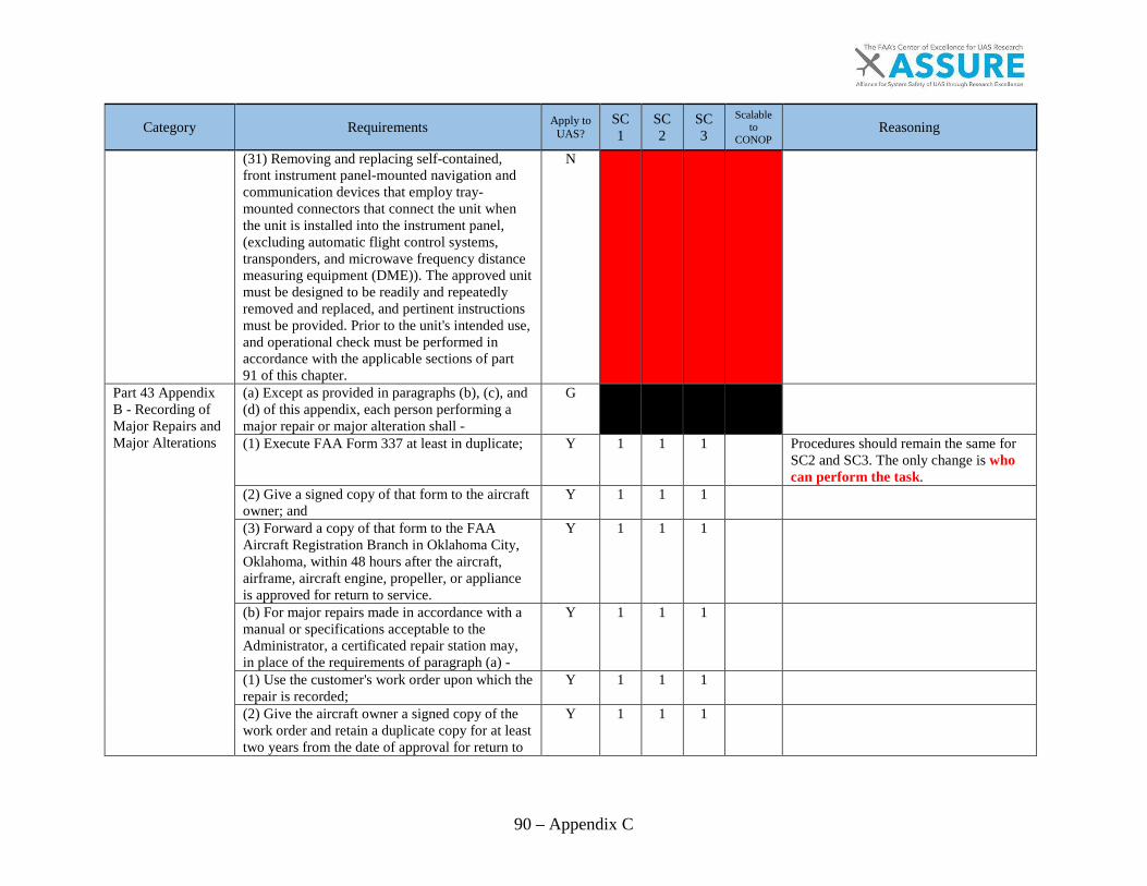
90 – Appendix C
Category Requirements Apply to UAS?
SC1
SC2
SC3
Scalable to
CONOP Reasoning
(31) Removing and replacing self-contained, front instrument panel-mounted navigation and communication devices that employ tray-mounted connectors that connect the unit when the unit is installed into the instrument panel, (excluding automatic flight control systems, transponders, and microwave frequency distance measuring equipment (DME)). The approved unit must be designed to be readily and repeatedly removed and replaced, and pertinent instructions must be provided. Prior to the unit's intended use, and operational check must be performed in accordance with the applicable sections of part 91 of this chapter.
N
Part 43 Appendix B - Recording of Major Repairs and Major Alterations
(a) Except as provided in paragraphs (b), (c), and (d) of this appendix, each person performing a major repair or major alteration shall -
G
(1) Execute FAA Form 337 at least in duplicate; Y 1 1 1
Procedures should remain the same for SC2 and SC3. The only change is who can perform the task.
(2) Give a signed copy of that form to the aircraft owner; and
Y 1 1 1
(3) Forward a copy of that form to the FAA Aircraft Registration Branch in Oklahoma City, Oklahoma, within 48 hours after the aircraft, airframe, aircraft engine, propeller, or appliance is approved for return to service.
Y 1 1 1
(b) For major repairs made in accordance with a manual or specifications acceptable to the Administrator, a certificated repair station may, in place of the requirements of paragraph (a) -
Y 1 1 1
(1) Use the customer's work order upon which the repair is recorded;
Y 1 1 1
(2) Give the aircraft owner a signed copy of the work order and retain a duplicate copy for at least two years from the date of approval for return to
Y 1 1 1
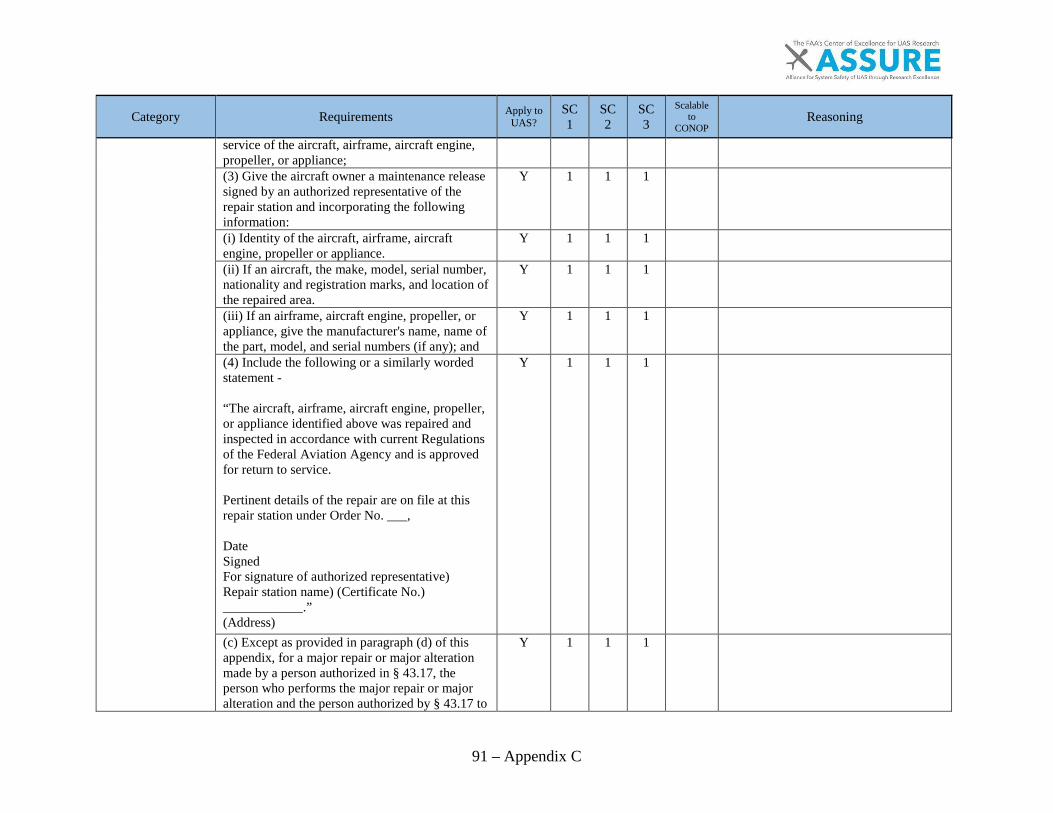
91 – Appendix C
Category Requirements Apply to UAS?
SC1
SC2
SC3
Scalable to
CONOP Reasoning
service of the aircraft, airframe, aircraft engine, propeller, or appliance; (3) Give the aircraft owner a maintenance release signed by an authorized representative of the repair station and incorporating the following information:
Y 1 1 1
(i) Identity of the aircraft, airframe, aircraft engine, propeller or appliance.
Y 1 1 1
(ii) If an aircraft, the make, model, serial number, nationality and registration marks, and location of the repaired area.
Y 1 1 1
(iii) If an airframe, aircraft engine, propeller, or appliance, give the manufacturer's name, name of the part, model, and serial numbers (if any); and
Y 1 1 1
(4) Include the following or a similarly worded statement - “The aircraft, airframe, aircraft engine, propeller, or appliance identified above was repaired and inspected in accordance with current Regulations of the Federal Aviation Agency and is approved for return to service. Pertinent details of the repair are on file at this repair station under Order No. ___, Date Signed For signature of authorized representative) Repair station name) (Certificate No.) ____________.” (Address)
Y 1 1 1
(c) Except as provided in paragraph (d) of this appendix, for a major repair or major alteration made by a person authorized in § 43.17, the person who performs the major repair or major alteration and the person authorized by § 43.17 to
Y 1 1 1

92 – Appendix C
Category Requirements Apply to UAS?
SC1
SC2
SC3
Scalable to
CONOP Reasoning
approve that work shall execute an FAA Form 337 at least in duplicate. A completed copy of that form shall be - (1) Given to the aircraft owner; and Y 1 1 1
(2) Forwarded to the Federal Aviation Administration, Aircraft Registration Branch, AFS-750, Post Office Box 25504, Oklahoma City, OK 73125, within 48 hours after the work is inspected.
Y 1 1 1
(d) For extended-range fuel tanks installed within the passenger compartment or a baggage compartment, the person who performs the work and the person authorized to approve the work by § 43.7 shall execute an FAA Form 337 in at least triplicate. A completed copy of that form shall be -
N
(1) Placed on board the aircraft as specified in § 91.417 of this chapter;
N
Exceptions for CS.
(2) Given to the aircraft owner; and Y 1 1 1
(3) Forwarded to the Federal Aviation Administration, Aircraft Registration Branch, AFS-751, Post Office Box 25724, Oklahoma City, OK 73125, within 48 hours after the work is inspected.
1 1
SC1- Should be available not necessary to send it in.
Appendix D to Part 43 – Scope and Detail of Items (as Applicable to the Particular Aircraft) To Be Included in Annual and 100-Hour Inspections
(a) Each person performing an annual or 100-hour inspection shall, before that inspection, remove or open all necessary inspection plates, access doors, fairing, and cowling. He shall thoroughly clean the aircraft and aircraft engine.
Y 1 1 1
Procedures should remain the same for SC2 and SC3. The only change is who can perform the task. Could also be performed per cycle for SC1. There should be some type of inspection but may not resemble manned. Cycles/hours TBD.
(b) Each person performing an annual or 100-hour inspection shall inspect (where applicable) the following components of the fuselage and hull group:
G
(1) Fabric and skin – for deterioration, distortion, other evidence of failure, and defective or insecure attachment of fittings.
Y 1 1 1

93 – Appendix C
Category Requirements Apply to UAS?
SC1
SC2
SC3
Scalable to
CONOP Reasoning
(2) Systems and components – for improper installation, apparent defects, and unsatisfactory operation.
Y 1 1 1
(3) Envelope, gas bags, ballast tanks, and related parts – for poor condition.
Y 1 1 1
(c) Each person performing an annual or 100-hour inspection shall inspect (where applicable) the following components of the cabin and cockpit group:
G
(1) Generally – for uncleanliness and loose equipment that might foul the controls.
Y 1 1 1
(2) Seats and safety belts – for poor condition and apparent defects.
Y
1
(3) Windows and windshields – for deterioration and breakage.
Y
1
(4) Instruments – for poor condition, mounting, marking, and (where practicable) improper operation.
Y 1 1 1
(5) Flight and engine controls – for improper installation and improper operation.
Y 1 1 1
(6) Batteries – for improper installation and improper charge.
Y 1 1 1
(7) All systems – for improper installation, poor general condition, apparent and obvious defects, and insecurity of attachment.
Y 1 1 1
(d) Each person performing an annual or 100-hour inspection shall inspect (where applicable) components of the engine and nacelle group as follows:
G
(1) Engine section – for visual evidence of excessive oil, fuel, or hydraulic leaks, and sources of such leaks.
Y
1 1
(2) Studs and nuts – for improper torquing and obvious defects.
Y 1 1 1

94 – Appendix C
Category Requirements Apply to UAS?
SC1
SC2
SC3
Scalable to
CONOP Reasoning
(3) Internal engine – for cylinder compressionand for metal particles or foreign matter onscreens and sump drain plugs. If there is weakcylinder compression, for improper internalcondition and improper internal tolerances.
Y 1 1
(4) Engine mount – for cracks, looseness ofmounting, and looseness of engine to mount
Y 1 1 1
(5) Flexible vibration dampeners – for poorcondition and deterioration.
Y 1 1 1
(6) Engine controls – for defects, improper travel,and improper safetying.
Y 1 1 1
(7) Lines, hoses, and clamps – for leaks,improper condition and looseness.
Y 1 1
(8) Exhaust stacks – for cracks, defects, andimproper attachment.
Y 1 1
(9) Accessories – for apparent defects in securityof mounting.
Y 1 1 1
(10) All systems – for improper installation, poorgeneral condition, defects, and insecureattachment.
Y 1 1 1
(11) Cowling – for cracks, and defects. Y 1 1 1 (e) Each person performing an annual or 100-hour inspection shall inspect (where applicable)the following components of the landing geargroup:
G
(1) All units – for poor condition and insecurityof attachment.
Y 1 1 1
(2) Shock absorbing devices – for improper oleofluid level.
Y 1 1
(3) Linkages, trusses, and members – for undueor excessive wear fatigue, and distortion.
Y 1 1 1
(4) Retracting and locking mechanism – forimproper operation.
Y 1 1 1
(5) Hydraulic lines – for leakage. Y 1 1 (6) Electrical system – for chafing and improperoperation of switches.
Y 1 1 1

95 – Appendix C
Category Requirements Apply to UAS?
SC1
SC2
SC3
Scalable to
CONOP Reasoning
(7) Wheels – for cracks, defects, and condition of bearings.
Y 1 1 1
(8) Tires – for wear and cuts. Y 1 1 1
(9) Brakes – for improper adjustment. Y
1 1
(10) Floats and skis – for insecure attachment and obvious or apparent defects.
Y 1 1 1
(f) Each person performing an annual or 100-hour inspection shall inspect (where applicable) all components of the wing and center section assembly for poor general condition, fabric or skin deterioration, distortion, evidence of failure, and insecurity of attachment.
Y 1 1 1
(g) Each person performing an annual or 100-hour inspection shall inspect (where applicable) all components and systems that make up the complete empennage assembly for poor general condition, fabric or skin deterioration, distortion, evidence of failure, insecure attachment, improper component installation, and improper component operation.
Y 1 1 1
(h) Each person performing an annual or 100-hour inspection shall inspect (where applicable) the following components of the propeller group:
G
(1) Propeller assembly – for cracks, nicks, binds, and oil leakage.
Y 1 1 1
(2) Bolts – for improper torquing and lack of safetying.
Y 1 1 1
(3) Anti-icing devices – for improper operations and obvious defects.
Y
1 1
(4) Control mechanisms – for improper operation, insecure mounting, and restricted travel.
Y 1 1 1
(i) Each person performing an annual or 100-hour inspection shall inspect (where applicable) the following components of the radio group:
G
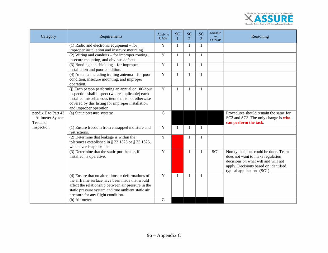
96 – Appendix C
Category Requirements Apply to UAS?
SC1
SC2
SC3
Scalable to
CONOP Reasoning
(1) Radio and electronic equipment – for improper installation and insecure mounting.
Y 1 1 1
(2) Wiring and conduits – for improper routing, insecure mounting, and obvious defects.
Y 1 1 1
(3) Bonding and shielding – for improper installation and poor condition.
Y 1 1 1
(4) Antenna including trailing antenna – for poor condition, insecure mounting, and improper operation.
Y 1 1 1
(j) Each person performing an annual or 100-hour inspection shall inspect (where applicable) each installed miscellaneous item that is not otherwise covered by this listing for improper installation and improper operation.
Y 1 1 1
pendix E to Part 43 – Altimeter System Test and Inspection
(a) Static pressure system: G
Procedures should remain the same for SC2 and SC3. The only change is who can perform the task.
(1) Ensure freedom from entrapped moisture and restrictions.
Y 1 1 1
(2) Determine that leakage is within the tolerances established in § 23.1325 or § 25.1325, whichever is applicable.
Y
1 1
(3) Determine that the static port heater, if installed, is operative.
Y
1 1 SC1 Non typical, but could be done. Team does not want to make regulation decisions on what will and will not apply. Decisions based on identified typical applications (SC1).
(4) Ensure that no alterations or deformations of the airframe surface have been made that would affect the relationship between air pressure in the static pressure system and true ambient static air pressure for any flight condition.
Y 1 1 1
(b) Altimeter: G
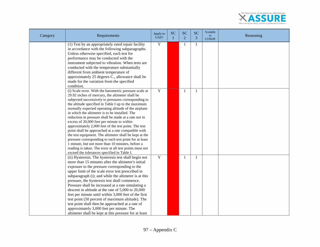
97 – Appendix C
Category Requirements Apply to UAS?
SC1
SC2
SC3
Scalable to
CONOP Reasoning
(1) Test by an appropriately rated repair facility in accordance with the following subparagraphs. Unless otherwise specified, each test for performance may be conducted with the instrument subjected to vibration. When tests are conducted with the temperature substantially different from ambient temperature of approximately 25 degrees C., allowance shall be made for the variation from the specified condition.
Y
1 1
(i) Scale error. With the barometric pressure scale at 29.92 inches of mercury, the altimeter shall be subjected successively to pressures corresponding to the altitude specified in Table I up to the maximum normally expected operating altitude of the airplane in which the altimeter is to be installed. The reduction in pressure shall be made at a rate not in excess of 20,000 feet per minute to within approximately 2,000 feet of the test point. The test point shall be approached at a rate compatible with the test equipment. The altimeter shall be kept at the pressure corresponding to each test point for at least 1 minute, but not more than 10 minutes, before a reading is taken. The error at all test points must not exceed the tolerances specified in Table I.
Y
1 1
(ii) Hysteresis. The hysteresis test shall begin not more than 15 minutes after the altimeter's initial exposure to the pressure corresponding to the upper limit of the scale error test prescribed in subparagraph (i); and while the altimeter is at this pressure, the hysteresis test shall commence. Pressure shall be increased at a rate simulating a descent in altitude at the rate of 5,000 to 20,000 feet per minute until within 3,000 feet of the first test point (50 percent of maximum altitude). The test point shall then be approached at a rate of approximately 3,000 feet per minute. The altimeter shall be kept at this pressure for at least
Y
1 1

98 – Appendix C
Category Requirements Apply to UAS?
SC1
SC2
SC3
Scalable to
CONOP Reasoning
5 minutes, but not more than 15 minutes, before the test reading is taken. After the reading has been taken, the pressure shall be increased further, in the same manner as before, until the pressure corresponding to the second test point (40 percent of maximum altitude) is reached. The altimeter shall be kept at this pressure for at least 1 minute, but not more than 10 minutes, before the test reading is taken. After the reading has been taken, the pressure shall be increased further, in the same manner as before, until atmospheric pressure is reached. The reading of the altimeter at either of the two test points shall not differ by more than the tolerance specified in Table II from the reading of the altimeter for the corresponding altitude recorded during the scale error test prescribed in paragraph (b)(i). (iii) After effect. Not more than 5 minutes after the completion of the hysteresis test prescribed in paragraph (b)(ii), the reading of the altimeter (corrected for any change in atmospheric pressure) shall not differ from the original atmospheric pressure reading by more than the tolerance specified in Table II.
Y
1 1
(iv) Friction. The altimeter shall be subjected to a steady rate of decrease of pressure approximating 750 feet per minute. At each altitude listed in Table III, the change in reading of the pointers after vibration shall not exceed the corresponding tolerance listed in Table III.
Y
1 1
(v) Case leak. The leakage of the altimeter case, when the pressure within it corresponds to an altitude of 18,000 feet, shall not change the altimeter reading by more than the tolerance shown in Table II during an interval of 1 minute.
Y
1 1
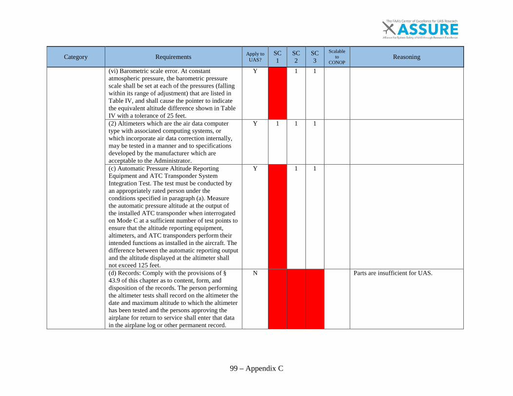
99 – Appendix C
Category Requirements Apply to UAS?
SC1
SC2
SC3
Scalable to
CONOP Reasoning
(vi) Barometric scale error. At constant atmospheric pressure, the barometric pressure scale shall be set at each of the pressures (falling within its range of adjustment) that are listed in Table IV, and shall cause the pointer to indicate the equivalent altitude difference shown in Table IV with a tolerance of 25 feet.
Y
1 1
(2) Altimeters which are the air data computer type with associated computing systems, or which incorporate air data correction internally, may be tested in a manner and to specifications developed by the manufacturer which are acceptable to the Administrator.
Y 1 1 1
(c) Automatic Pressure Altitude Reporting Equipment and ATC Transponder System Integration Test. The test must be conducted by an appropriately rated person under the conditions specified in paragraph (a). Measure the automatic pressure altitude at the output of the installed ATC transponder when interrogated on Mode C at a sufficient number of test points to ensure that the altitude reporting equipment, altimeters, and ATC transponders perform their intended functions as installed in the aircraft. The difference between the automatic reporting output and the altitude displayed at the altimeter shall not exceed 125 feet.
Y
1 1
(d) Records: Comply with the provisions of § 43.9 of this chapter as to content, form, and disposition of the records. The person performing the altimeter tests shall record on the altimeter the date and maximum altitude to which the altimeter has been tested and the persons approving the airplane for return to service shall enter that data in the airplane log or other permanent record.
N
Parts are insufficient for UAS.
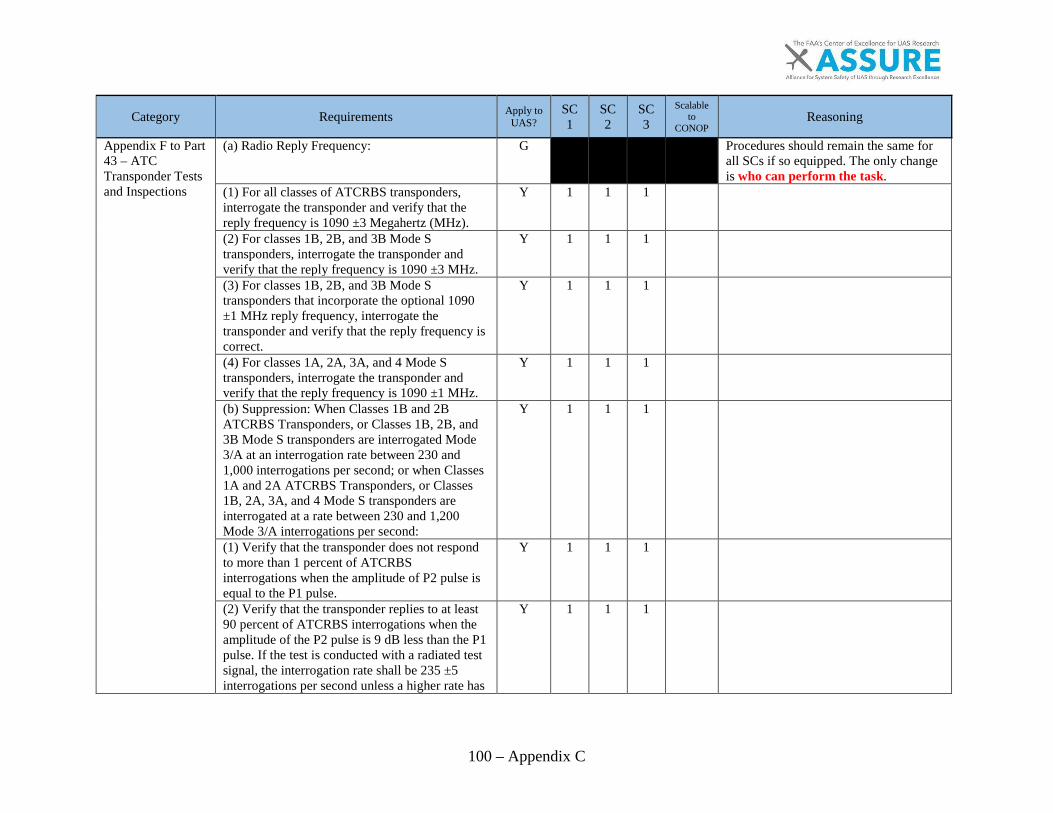
100 – Appendix C
Category Requirements Apply to UAS?
SC1
SC2
SC3
Scalable to
CONOP Reasoning
Appendix F to Part 43 – ATC Transponder Tests and Inspections
(a) Radio Reply Frequency: G
Procedures should remain the same for all SCs if so equipped. The only change is who can perform the task.
(1) For all classes of ATCRBS transponders, interrogate the transponder and verify that the reply frequency is 1090 ±3 Megahertz (MHz).
Y 1 1 1
(2) For classes 1B, 2B, and 3B Mode S transponders, interrogate the transponder and verify that the reply frequency is 1090 ±3 MHz.
Y 1 1 1
(3) For classes 1B, 2B, and 3B Mode S transponders that incorporate the optional 1090 ±1 MHz reply frequency, interrogate the transponder and verify that the reply frequency is correct.
Y 1 1 1
(4) For classes 1A, 2A, 3A, and 4 Mode S transponders, interrogate the transponder and verify that the reply frequency is 1090 ±1 MHz.
Y 1 1 1
(b) Suppression: When Classes 1B and 2B ATCRBS Transponders, or Classes 1B, 2B, and 3B Mode S transponders are interrogated Mode 3/A at an interrogation rate between 230 and 1,000 interrogations per second; or when Classes 1A and 2A ATCRBS Transponders, or Classes 1B, 2A, 3A, and 4 Mode S transponders are interrogated at a rate between 230 and 1,200 Mode 3/A interrogations per second:
Y 1 1 1
(1) Verify that the transponder does not respond to more than 1 percent of ATCRBS interrogations when the amplitude of P2 pulse is equal to the P1 pulse.
Y 1 1 1
(2) Verify that the transponder replies to at least 90 percent of ATCRBS interrogations when the amplitude of the P2 pulse is 9 dB less than the P1 pulse. If the test is conducted with a radiated test signal, the interrogation rate shall be 235 ±5 interrogations per second unless a higher rate has
Y 1 1 1
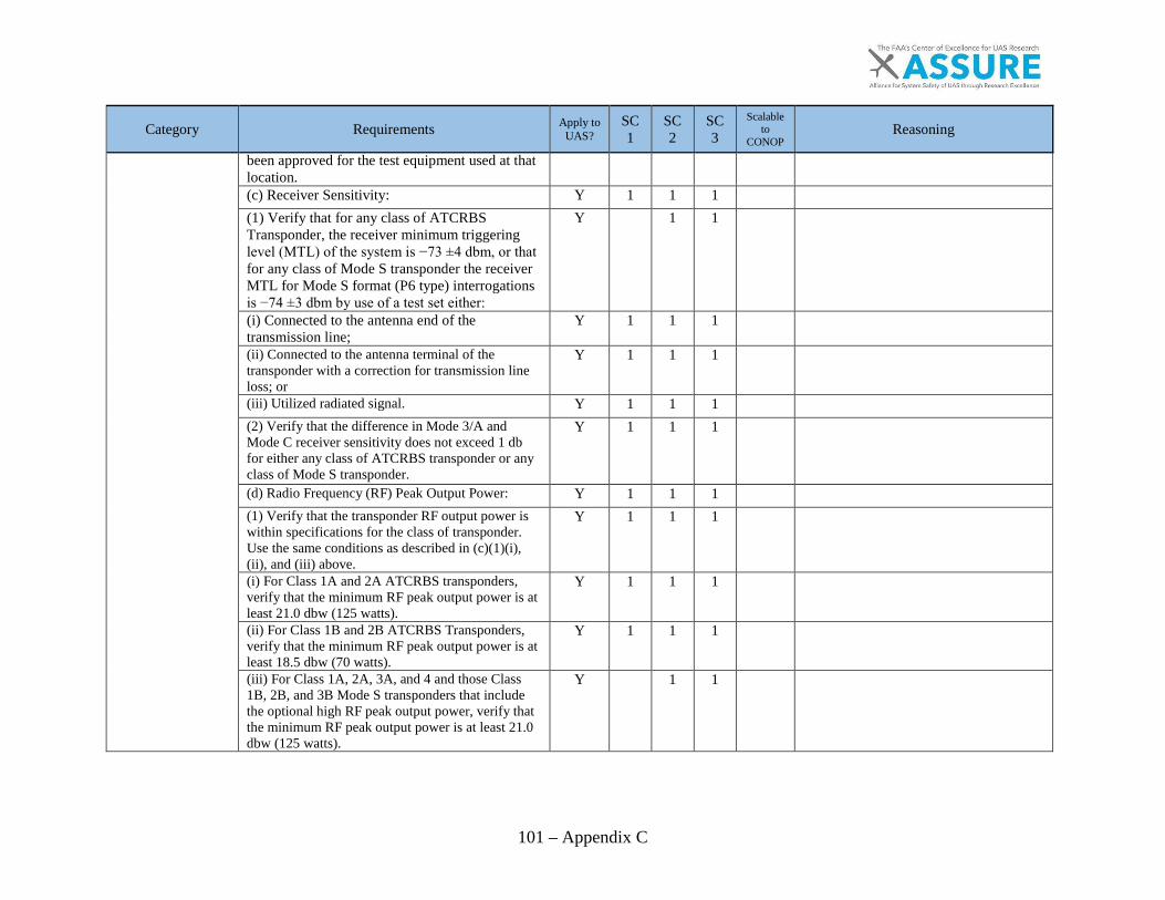
101 – Appendix C
Category Requirements Apply to UAS?
SC1
SC2
SC3
Scalable to
CONOP Reasoning
been approved for the test equipment used at that location. (c) Receiver Sensitivity: Y 1 1 1
(1) Verify that for any class of ATCRBS Transponder, the receiver minimum triggering level (MTL) of the system is −73 ±4 dbm, or that for any class of Mode S transponder the receiver MTL for Mode S format (P6 type) interrogations is −74 ±3 dbm by use of a test set either:
Y
1 1
(i) Connected to the antenna end of the transmission line;
Y 1 1 1
(ii) Connected to the antenna terminal of the transponder with a correction for transmission line loss; or
Y 1 1 1
(iii) Utilized radiated signal. Y 1 1 1
(2) Verify that the difference in Mode 3/A and Mode C receiver sensitivity does not exceed 1 db for either any class of ATCRBS transponder or any class of Mode S transponder.
Y 1 1 1
(d) Radio Frequency (RF) Peak Output Power: Y 1 1 1
(1) Verify that the transponder RF output power is within specifications for the class of transponder. Use the same conditions as described in (c)(1)(i), (ii), and (iii) above.
Y 1 1 1
(i) For Class 1A and 2A ATCRBS transponders, verify that the minimum RF peak output power is at least 21.0 dbw (125 watts).
Y 1 1 1
(ii) For Class 1B and 2B ATCRBS Transponders, verify that the minimum RF peak output power is at least 18.5 dbw (70 watts).
Y 1 1 1
(iii) For Class 1A, 2A, 3A, and 4 and those Class 1B, 2B, and 3B Mode S transponders that include the optional high RF peak output power, verify that the minimum RF peak output power is at least 21.0 dbw (125 watts).
Y
1 1

102 – Appendix C
Category Requirements Apply to UAS?
SC1
SC2
SC3
Scalable to
CONOP Reasoning
(iv) For Classes 1B, 2B, and 3B Mode S transponders, verify that the minimum RF peak output power is at least 18.5 dbw (70 watts).
Y
1 1
(v) For any class of ATCRBS or any class of Mode S transponders, verify that the maximum RF peak output power does not exceed 27.0 dbw (500 watts).
Y 1 1 1
(e) Mode S Diversity Transmission Channel Isolation: For any class of Mode S transponder that incorporates diversity operation, verify that the RF peak output power transmitted from the selected antenna exceeds the power transmitted from the nonselected antenna by at least 20 db.
Y 1 1 1
(f) Mode S Address: Interrogate the Mode S transponder and verify that it replies only to its assigned address. Use the correct address and at least two incorrect addresses. The interrogations should be made at a nominal rate of 50 interrogations per second.
Y 1 1 1
(g) Mode S Formats: Interrogate the Mode S transponder with uplink formats (UF) for which it is equipped and verify that the replies are made in the correct format. Use the surveillance formats UF = 4 and 5. Verify that the altitude reported in the replies to UF = 4 are the same as that reported in a valid ATCRBS Mode C reply. Verify that the identity reported in the replies to UF = 5 are the same as that reported in a valid ATCRBS Mode 3/A reply. If the transponder is so equipped, use the communication formats UF = 20, 21, and 24.
Y 1 1 1
(h) Mode S All-Call Interrogations: Interrogate the Mode S transponder with the Mode S-only all-call format UF = 11, and the ATCRBS/Mode S all-call formats (1.6 microsecond P4 pulse) and verify that the correct address and capability are reported in the replies (downlink format DF = 11).
Y 1 1 1
(i) ATCRBS-Only All-Call Interrogation: Interrogate the Mode S transponder with the ATCRBS-only all-call interrogation (0.8
Y 1 1 1
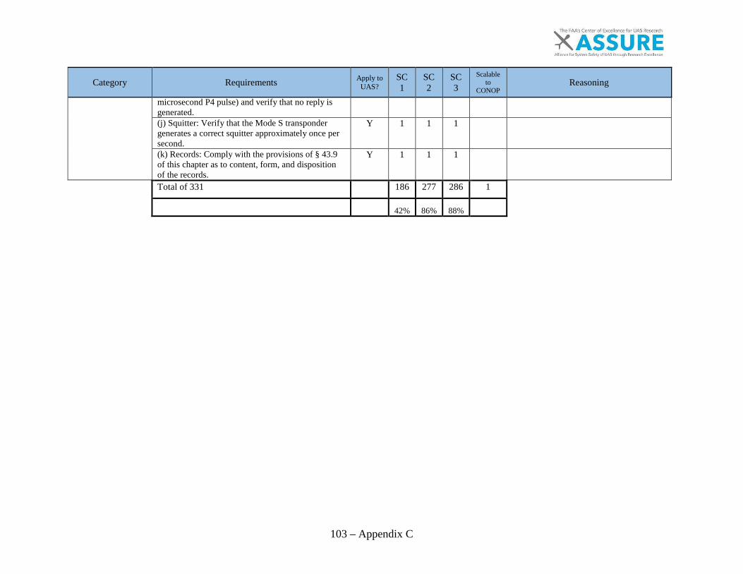
103 – Appendix C
Category Requirements Apply to UAS?
SC1
SC2
SC3
Scalable to
CONOP Reasoning
microsecond P4 pulse) and verify that no reply is generated. (j) Squitter: Verify that the Mode S transponder generates a correct squitter approximately once per second.
Y 1 1 1
(k) Records: Comply with the provisions of § 43.9 of this chapter as to content, form, and disposition of the records.
Y 1 1 1
Total of 331
186 277 286 1
42% 86% 88%
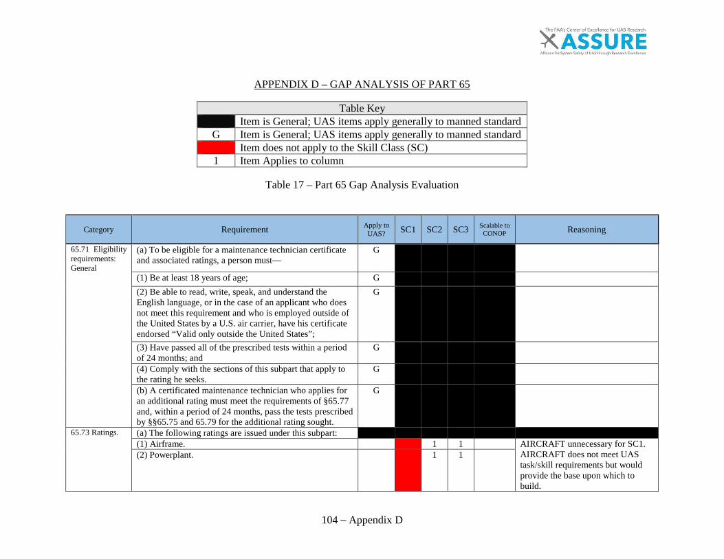
104 – Appendix D
APPENDIX D – GAP ANALYSIS OF PART 65
Table Key Item is General; UAS items apply generally to manned standard
G Item is General; UAS items apply generally to manned standard Item does not apply to the Skill Class (SC) 1 Item Applies to column
Table 17 – Part 65 Gap Analysis Evaluation
Category Requirement Apply to UAS? SC1 SC2 SC3 Scalable to
CONOP Reasoning
65.71 Eligibility requirements: General
(a) To be eligible for a maintenance technician certificate and associated ratings, a person must—
G
(1) Be at least 18 years of age; G
(2) Be able to read, write, speak, and understand the English language, or in the case of an applicant who does not meet this requirement and who is employed outside of the United States by a U.S. air carrier, have his certificate endorsed “Valid only outside the United States”;
G
(3) Have passed all of the prescribed tests within a period of 24 months; and
G
(4) Comply with the sections of this subpart that apply to the rating he seeks.
G
(b) A certificated maintenance technician who applies for an additional rating must meet the requirements of §65.77 and, within a period of 24 months, pass the tests prescribed by §§65.75 and 65.79 for the additional rating sought.
G
65.73 Ratings. (a) The following ratings are issued under this subpart:
(1) Airframe.
1 1
AIRCRAFT unnecessary for SC1. AIRCRAFT does not meet UAS task/skill requirements but would provide the base upon which to build.
(2) Powerplant.
1 1

105 – Appendix D
Category Requirement Apply to UAS? SC1 SC2 SC3 Scalable to
CONOP Reasoning
(b) A maintenance technician certificate with an aircraft or aircraft engine rating, or both, that was issued before, and was valid on, June 15, 1952, is equal to a maintenance technician certificate with an airframe or powerplant rating, or both, as the case may be, and may be exchanged for such a corresponding certificate and rating or ratings.
N
65.75 Knowledge requirements.
(a) Each applicant for a maintenance technician certificate or rating must, after meeting the applicable experience requirements of §65.77, pass a written test covering the construction and maintenance of aircraft appropriate to the rating he seeks, the regulations in this subpart, and the applicable provisions of parts 43 and 91 of this chapter. The basic principles covering the installation and maintenance of propellers are included in the powerplant test.
1 1
(b) The applicant must pass each section of the test before applying for the oral and practical tests prescribed by §65.79. A report of the written test is sent to the applicant.
1 1
65.77 Experience requirements.
Each applicant for a maintenance technician certificate or rating must present either an appropriate graduation certificate or certificate of completion from a certificated aviation maintenance technician school or documentary evidence, satisfactory to the Administrator, of— (a) At least 18 months of practical experience with the procedures, practices, materials, tools, machine tools, and equipment generally used in constructing, maintaining, or altering airframes, or powerplants appropriate to the rating sought; or
1 1
(b) At least 30 months of practical experience concurrently performing the duties appropriate to both the airframe and powerplant ratings.
1 1
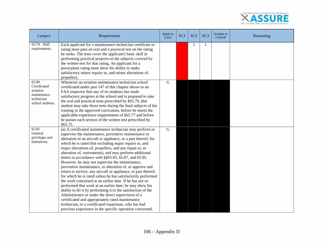
106 – Appendix D
Category Requirement Apply to UAS? SC1 SC2 SC3 Scalable to
CONOP Reasoning
65.79 Skill requirements.
Each applicant for a maintenance technician certificate or rating must pass an oral and a practical test on the rating he seeks. The tests cover the applicant's basic skill in performing practical projects on the subjects covered by the written test for that rating. An applicant for a powerplant rating must show his ability to make satisfactory minor repairs to, and minor alterations of, propellers.
1 1
65.80 Certificated aviation maintenance technician school students.
Whenever an aviation maintenance technician school certificated under part 147 of this chapter shows to an FAA inspector that any of its students has made satisfactory progress at the school and is prepared to take the oral and practical tests prescribed by §65.79, that student may take those tests during the final subjects of his training in the approved curriculum, before he meets the applicable experience requirements of §65.77 and before he passes each section of the written test prescribed by §65.75.
G
65.81 General privileges and limitations.
(a) A certificated maintenance technician may perform or supervise the maintenance, preventive maintenance or alteration of an aircraft or appliance, or a part thereof, for which he is rated (but excluding major repairs to, and major alterations of, propellers, and any repair to, or alteration of, instruments), and may perform additional duties in accordance with §§65.85, 65.87, and 65.95. However, he may not supervise the maintenance, preventive maintenance, or alteration of, or approve and return to service, any aircraft or appliance, or part thereof, for which he is rated unless he has satisfactorily performed the work concerned at an earlier date. If he has not so performed that work at an earlier date, he may show his ability to do it by performing it to the satisfaction of the Administrator or under the direct supervision of a certificated and appropriately rated maintenance technician, or a certificated repairman, who has had previous experience in the specific operation concerned.
G
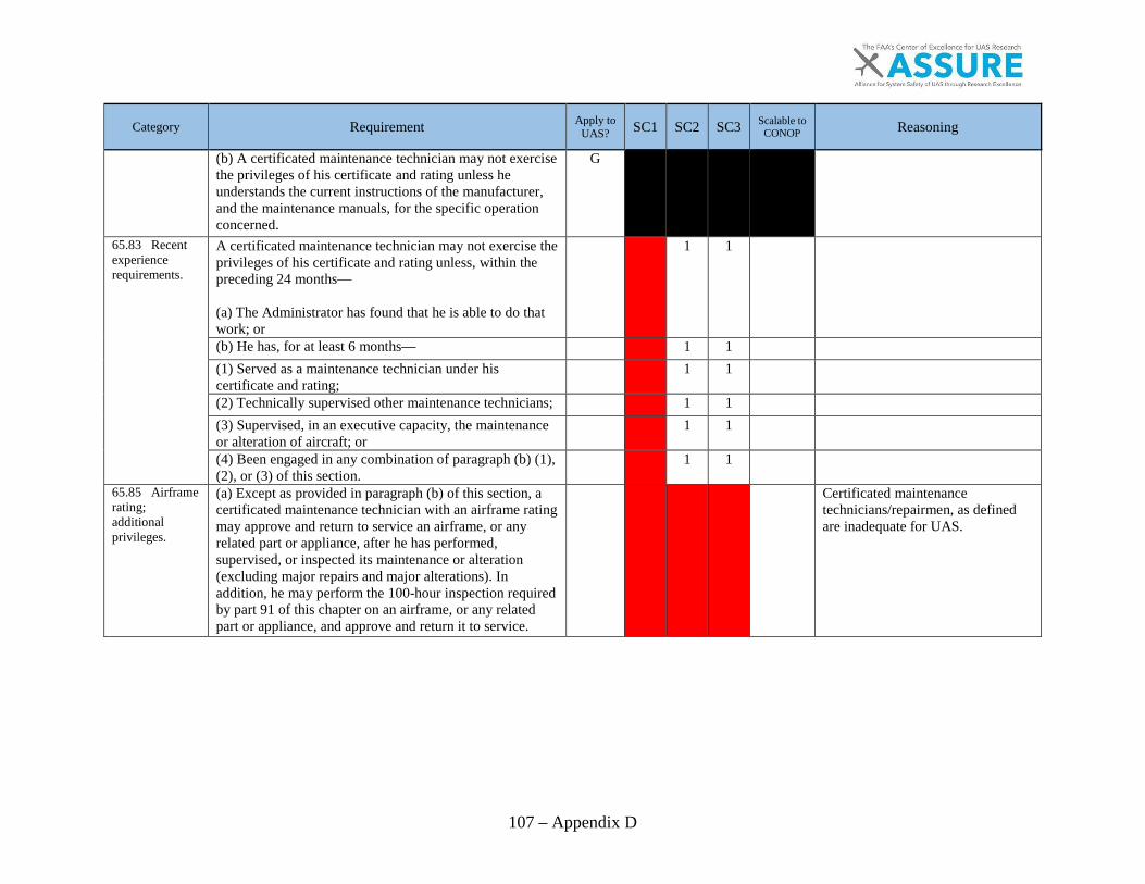
107 – Appendix D
Category Requirement Apply to UAS? SC1 SC2 SC3 Scalable to
CONOP Reasoning
(b) A certificated maintenance technician may not exercise the privileges of his certificate and rating unless he understands the current instructions of the manufacturer, and the maintenance manuals, for the specific operation concerned.
G
65.83 Recent experience requirements.
A certificated maintenance technician may not exercise the privileges of his certificate and rating unless, within the preceding 24 months— (a) The Administrator has found that he is able to do that work; or
1 1
(b) He has, for at least 6 months—
1 1
(1) Served as a maintenance technician under his certificate and rating;
1 1
(2) Technically supervised other maintenance technicians;
1 1
(3) Supervised, in an executive capacity, the maintenance or alteration of aircraft; or
1 1
(4) Been engaged in any combination of paragraph (b) (1), (2), or (3) of this section.
1 1
65.85 Airframe rating; additional privileges.
(a) Except as provided in paragraph (b) of this section, a certificated maintenance technician with an airframe rating may approve and return to service an airframe, or any related part or appliance, after he has performed, supervised, or inspected its maintenance or alteration (excluding major repairs and major alterations). In addition, he may perform the 100-hour inspection required by part 91 of this chapter on an airframe, or any related part or appliance, and approve and return it to service.
Certificated maintenance technicians/repairmen, as defined are inadequate for UAS.

108 – Appendix D
Category Requirement Apply to UAS? SC1 SC2 SC3 Scalable to
CONOP Reasoning
(b) A certificated maintenance technician with an airframe rating can approve and return to service an airframe, or any related part or appliance, of an aircraft with a special airworthiness certificate in the light-sport category after performing and inspecting a major repair or major alteration for products that are not produced under an FAA approval provided the work was performed in accordance with instructions developed by the manufacturer or a person acceptable to the FAA.
65.87 Powerplant rating; additional privileges.
(a) Except as provided in paragraph (b) of this section, a certificated maintenance technician with a powerplant rating may approve and return to service a powerplant or propeller or any related part or appliance, after he has performed, supervised, or inspected its maintenance or alteration (excluding major repairs and major alterations). In addition, he may perform the 100-hour inspection required by part 91 of this chapter on a powerplant or propeller, or any part thereof, and approve and return it to service.
(b) A certificated maintenance technician with a powerplant rating can approve and return to service a powerplant or propeller, or any related part or appliance, of an aircraft with a special airworthiness certificate in the light-sport category after performing and inspecting a major repair or major alteration for products that are not produced under an FAA approval, provided the work was performed in accordance with instructions developed by the manufacturer or a person acceptable to the FAA.
65.89 Display of certificate.
Each person who holds a maintenance technician certificate shall keep it within the immediate area where he normally exercises the privileges of the certificate and shall present it for inspection upon the request of the Administrator or an authorized representative of the National Transportation Safety Board, or of any Federal, State, or local law enforcement officer.
N
Certificates, as required, should be in work area. Maintenance technician certificate, as currently defined, is inadequate for UAS.
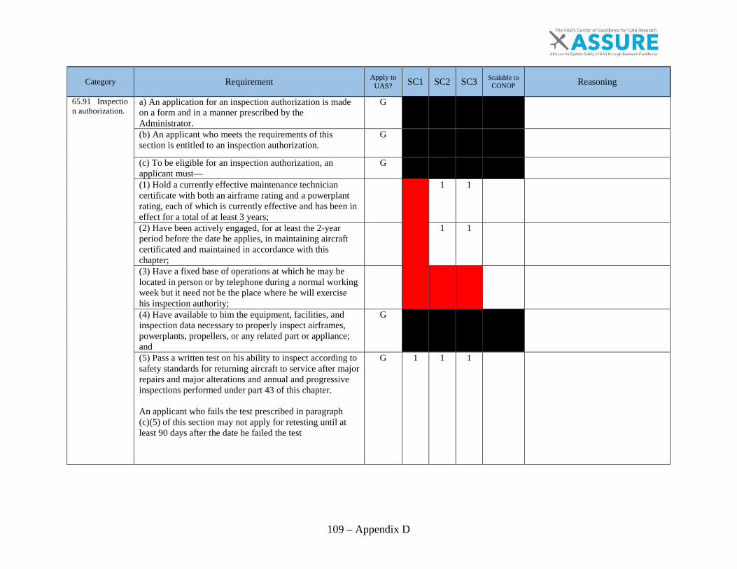
109 – Appendix D
Category Requirement Apply to UAS? SC1 SC2 SC3 Scalable to
CONOP Reasoning
65.91 Inspection authorization.
a) An application for an inspection authorization is madeon a form and in a manner prescribed by theAdministrator.
G
(b) An applicant who meets the requirements of thissection is entitled to an inspection authorization.
G
(c) To be eligible for an inspection authorization, anapplicant must—
G
(1) Hold a currently effective maintenance techniciancertificate with both an airframe rating and a powerplantrating, each of which is currently effective and has been ineffect for a total of at least 3 years;
1 1
(2) Have been actively engaged, for at least the 2-yearperiod before the date he applies, in maintaining aircraftcertificated and maintained in accordance with thischapter;
1 1
(3) Have a fixed base of operations at which he may belocated in person or by telephone during a normal workingweek but it need not be the place where he will exercisehis inspection authority;(4) Have available to him the equipment, facilities, andinspection data necessary to properly inspect airframes,powerplants, propellers, or any related part or appliance;and
G
(5) Pass a written test on his ability to inspect according tosafety standards for returning aircraft to service after majorrepairs and major alterations and annual and progressiveinspections performed under part 43 of this chapter.
An applicant who fails the test prescribed in paragraph (c)(5) of this section may not apply for retesting until at least 90 days after the date he failed the test
G 1 1 1

110 – Appendix D
Category Requirement Apply to UAS? SC1 SC2 SC3 Scalable to
CONOP Reasoning
65.92 Inspection authorization: Duration.
(a) Each inspection authorization expires on March 31 of each odd-numbered year. However, the holder may exercise the privileges of that authorization only while he holds a currently effective maintenance technician certificate with both a currently effective airframe rating and a currently effective powerplant rating.
G
(b) An inspection authorization ceases to be effective whenever any of the following occurs:
G
(1) The authorization is surrendered, suspended, or revoked.
G
(2) The holder no longer has a fixed base of operation. G
(3) The holder no longer has the equipment, facilities, and inspection data required by §65.91(c) (3) and (4) for issuance of his authorization.
G
(c) The holder of an inspection authorization that is suspended or revoked shall, upon the Administrator's request, return it to the Administrator.
G
65.93 Inspection authorization: Renewal.
(a) To be eligible for renewal of an inspection authorization for a 2-year period an applicant must present evidence during the month of March of each odd-numbered year, at an FAA Flight Standards District Office or an International Field Office, that the applicant still meets the requirements of §65.91(c) (1) through (4). In addition, during the time the applicant held the inspection authorization, the applicant must show completion of one of the activities in §65.93(a) (1) through (5) below by March 31 of the first year of the 2-year inspection authorization period, and completion of one of the five activities during the second year of the 2-year period:
(1) Performed at least one annual inspection for each 90 days that the applicant held the current authority; or
1 1
Annuals unnecessary for SC1.
(2) Performed at least two major repairs or major alterations for each 90 days that the applicant held the current authority; or
1 1
Major repair or major alteration definitions may not fit SC1.
(3) Performed or supervised and approved at least one progressive inspection in accordance with standards prescribed by the Administrator; or
G

111 – Appendix D
Category Requirement Apply to UAS? SC1 SC2 SC3 Scalable to
CONOP Reasoning
(4) Attended and successfully completed a refresher course, acceptable to the Administrator, of not less than 8 hours of instruction; or
1 1
Unnecessary for SC1.
(5) Passed an oral test by an FAA inspector to determine that the applicant's knowledge of applicable regulations and standards is current.
N 1 1 1
Inspection authority as currently defined is inadequate for UAS considerations. Once training considerations are address these could apply.
(b) The holder of an inspection authorization that has been in effect:
N 1 1 1
(1) for less than 90 days before the expiration date need not comply with paragraphs (a)(1) through (5) of this section.
N 1 1 1
(2) for less than 90 days before March 31 of an even-numbered year need not comply with paragraphs (a)(1) through (5) of this section for the first year of the 2-year inspection authorization period.
N 1 1 1
(c) An inspection authorization holder who does not complete one of the activities set forth in §65.93(a) (1) through (5) of this section by March 31 of the first year of the 2-year inspection authorization period may not exercise inspection authorization privileges after March 31 of the first year. The inspection authorization holder may resume exercising inspection authorization privileges after passing an oral test from an FAA inspector to determine that the applicant's knowledge of the applicable regulations and standards is current. An inspection authorization holder who passes this oral test is deemed to have completed the requirements of §65.93(a) (1) through (5) by March 31 of the first year.
N 1 1 1
65.95 Inspection authorization: Privileges and limitations.
(a) The holder of an inspection authorization may— N 1 1 1
(1) Inspect and approve for return to service any aircraft or related part or appliance (except any aircraft maintained in accordance with a continuous airworthiness program under part 121 of this chapter) after a major repair or major alteration to it in accordance with part 43 [New] of this chapter, if the work was done in accordance with technical data approved by the Administrator; and
N 1 1 1
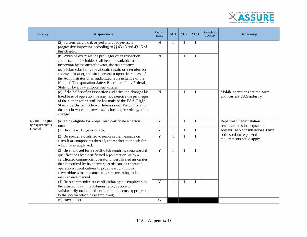
112 – Appendix D
Category Requirement Apply to UAS? SC1 SC2 SC3 Scalable to
CONOP Reasoning
(2) Perform an annual, or perform or supervise a progressive inspection according to §§43.13 and 43.15 of this chapter.
N 1 1 1
(b) When he exercises the privileges of an inspection authorization the holder shall keep it available for inspection by the aircraft owner, the maintenance technician submitting the aircraft, repair, or alteration for approval (if any), and shall present it upon the request of the Administrator or an authorized representative of the National Transportation Safety Board, or of any Federal, State, or local law enforcement officer.
N 1 1 1
(c) If the holder of an inspection authorization changes his fixed base of operation, he may not exercise the privileges of the authorization until he has notified the FAA Flight Standards District Office or International Field Office for the area in which the new base is located, in writing, of the change.
N 1 1 1
Mobile operations are the norm with current UAS industry.
65.101 Eligibility requirements: General
(a) To be eligible for a repairman certificate a person must—
Y 1 1 1
Repairman/ repair station certification is inadequate to address UAS considerations. Once addressed these general requirements could apply.
(1) Be at least 18 years of age; Y 1 1 1
(2) Be specially qualified to perform maintenance on aircraft or components thereof, appropriate to the job for which he is employed;
Y 1 1 1
(3) Be employed for a specific job requiring those special qualifications by a certificated repair station, or by a certificated commercial operator or certificated air carrier, that is required by its operating certificate or approved operations specifications to provide a continuous airworthiness maintenance program according to its maintenance manual
Y 1 1 1
(4) Be recommended for certification by his employer, to the satisfaction of the Administrator, as able to satisfactorily maintain aircraft or components, appropriate to the job for which he is employed;
Y 1 1 1
(5) Have either— G
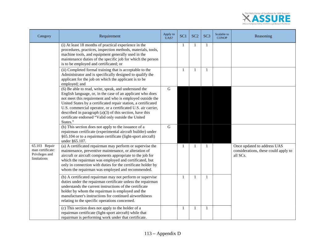
113 – Appendix D
Category Requirement Apply to UAS? SC1 SC2 SC3 Scalable to
CONOP Reasoning
(i) At least 18 months of practical experience in the procedures, practices, inspection methods, materials, tools, machine tools, and equipment generally used in the maintenance duties of the specific job for which the person is to be employed and certificated; or
1 1 1
(ii) Completed formal training that is acceptable to the Administrator and is specifically designed to qualify the applicant for the job on which the applicant is to be employed; and
1 1 1
(6) Be able to read, write, speak, and understand the English language, or, in the case of an applicant who does not meet this requirement and who is employed outside the United States by a certificated repair station, a certificated U.S. commercial operator, or a certificated U.S. air carrier, described in paragraph (a)(3) of this section, have this certificate endorsed “Valid only outside the United States.”
G
(b) This section does not apply to the issuance of a repairman certificate (experimental aircraft builder) under §65.104 or to a repairman certificate (light-sport aircraft) under §65.107.
G
65.103 Repairman certificate: Privileges and limitations
(a) A certificated repairman may perform or supervise the maintenance, preventive maintenance, or alteration of aircraft or aircraft components appropriate to the job for which the repairman was employed and certificated, but only in connection with duties for the certificate holder by whom the repairman was employed and recommended.
1 1 1
Once updated to address UAS considerations, these could apply to all SCs.
(b) A certificated repairman may not perform or supervise duties under the repairman certificate unless the repairman understands the current instructions of the certificate holder by whom the repairman is employed and the manufacturer's instructions for continued airworthiness relating to the specific operations concerned.
1 1 1
(c) This section does not apply to the holder of a repairman certificate (light-sport aircraft) while that repairman is performing work under that certificate.
1 1 1

114 – Appendix D
Category Requirement Apply to UAS? SC1 SC2 SC3 Scalable to
CONOP Reasoning
65.104 Repairman certificate—experimental aircraft builder—Eligibility, privileges and limitations.
(a) To be eligible for a repairman certificate (experimental aircraft builder), an individual must—
Repairman certificate is very much like what is currently done today within the UAS industry. (1) Be at least 18 years of age;
1 1 1
(2) Be the primary builder of the aircraft to which the privileges of the certificate are applicable;
1 1 1
(3) Show to the satisfaction of the Administrator that the individual has the requisite skill to determine whether the aircraft is in a condition for safe operations; and
Y 1 1 1
Does the Administrator currently have the knowledge to determine this?
(4) Be a citizen of the United States or an individual citizen of a foreign country who has lawfully been admitted for permanent residence in the United States.
Y 1 1 1
(b) The holder of a repairman certificate (experimental aircraft builder) may perform condition inspections on the aircraft constructed by the holder in accordance with the operating limitations of that aircraft.
1 1 1
(c) Section 65.103 does not apply to the holder of a repairman certificate (experimental aircraft builder) while performing under that certificate
N
No UAS repairman certificate currently exists.
65.105 Display of certificate.
Each person who holds a repairman certificate shall keep it within the immediate area where he normally exercises the privileges of the certificate and shall present it for inspection upon the request of the Administrator or an authorized representative of the National Transportation Safety Board, or of any Federal, State, or local law enforcement officer.
N
Once UAS Repairman certificate is established this would apply.
65.107 Repairman certificate (light-sport aircraft): Eligibility, privileges, and limits.
(a) Use the following table to determine your eligibility for a repairman certificate (light-sport aircraft) and appropriate rating: To be eligible for
1 1
While LSA's cannot be commercial, the equivalent maintenance rating may be what we are looking for with SC2 and SC1 outside of the scope of Part 107.
(1) A repairman certificate (light-sport aircraft)
1 1
(i) Be at least 18 years old,
1 1

115 – Appendix D
Category Requirement Apply to UAS? SC1 SC2 SC3 Scalable to
CONOP Reasoning
(ii) Be able to read, speak, write, and understand English. If for medical reasons you cannot meet one of these requirements, the FAA may place limits on your repairman certificate necessary to safely perform the actions authorized by the certificate and rating,
1 1
(iii) Demonstrate the requisite skill to determine whether a light-sport aircraft is in a condition for safe operation, and
1 1
(iv) Be a citizen of the United States, or a citizen of a foreign country who has been lawfully admitted for permanent residence in the United States.
G
(2) A repairman certificate (light-sport aircraft) with an inspection rating
1 1
(i) Meet the requirements of paragraph (a)(1) of this section, and
1 1
(ii) Complete a 16-hour training course acceptable to the FAA on inspecting the particular class of experimental light-sport aircraft for which you intend to exercise the privileges of this rating.
No course with FAA approval exists.
(3) A repairman certificate (light-sport aircraft) with a maintenance rating
1 1
(i) Meet the requirements of paragraph (a)(1) of this section, and
1 1
(ii) Complete a training course acceptable to the FAA on maintaining the particular class of light-sport aircraft for which you intend to exercise the privileges of this rating. The training course must, at a minimum, provide the following number of hours of instruction:
1 1
No course with FAA approval exists.
(A) For airplane class privileges—120-hours,
1 1
Inadequate for UAS considerations. (B) For weight-shift control aircraft class privileges—104 hours,
Not relevent to UAS.
(C) For powered parachute class privileges—104 hours,
Not relevent to UAS. (D) For lighter than air class privileges—80 hours,
1 1
Inadequate for UAS considerations.
(E) For glider class privileges—80 hours.
Not relevent to UAS.
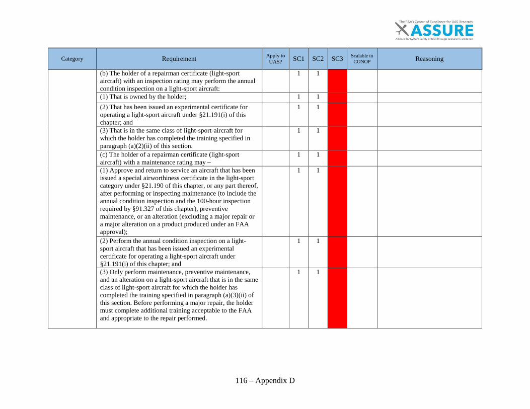
116 – Appendix D
Category Requirement Apply to UAS? SC1 SC2 SC3 Scalable to
CONOP Reasoning
(b) The holder of a repairman certificate (light-sport aircraft) with an inspection rating may perform the annual condition inspection on a light-sport aircraft:
1 1
(1) That is owned by the holder;
1 1
(2) That has been issued an experimental certificate for operating a light-sport aircraft under §21.191(i) of this chapter; and
1 1
(3) That is in the same class of light-sport-aircraft for which the holder has completed the training specified in paragraph (a)(2)(ii) of this section.
1 1
(c) The holder of a repairman certificate (light-sport aircraft) with a maintenance rating may –
1 1
(1) Approve and return to service an aircraft that has been issued a special airworthiness certificate in the light-sport category under §21.190 of this chapter, or any part thereof, after performing or inspecting maintenance (to include the annual condition inspection and the 100-hour inspection required by §91.327 of this chapter), preventive maintenance, or an alteration (excluding a major repair or a major alteration on a product produced under an FAA approval);
1 1
(2) Perform the annual condition inspection on a light-sport aircraft that has been issued an experimental certificate for operating a light-sport aircraft under §21.191(i) of this chapter; and
1 1
(3) Only perform maintenance, preventive maintenance, and an alteration on a light-sport aircraft that is in the same class of light-sport aircraft for which the holder has completed the training specified in paragraph (a)(3)(ii) of this section. Before performing a major repair, the holder must complete additional training acceptable to the FAA and appropriate to the repair performed.
1 1
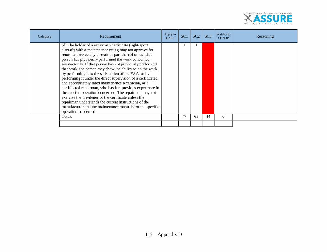
117 – Appendix D
Category Requirement Apply to UAS? SC1 SC2 SC3 Scalable to
CONOP Reasoning
(d) The holder of a repairman certificate (light-sport aircraft) with a maintenance rating may not approve for return to service any aircraft or part thereof unless that person has previously performed the work concerned satisfactorily. If that person has not previously performed that work, the person may show the ability to do the work by performing it to the satisfaction of the FAA, or by performing it under the direct supervision of a certificated and appropriately rated maintenance technician, or a certificated repairman, who has had previous experience in the specific operation concerned. The repairman may not exercise the privileges of the certificate unless the repairman understands the current instructions of the manufacturer and the maintenance manuals for the specific operation concerned.
1 1
Totals
47 65 44 0
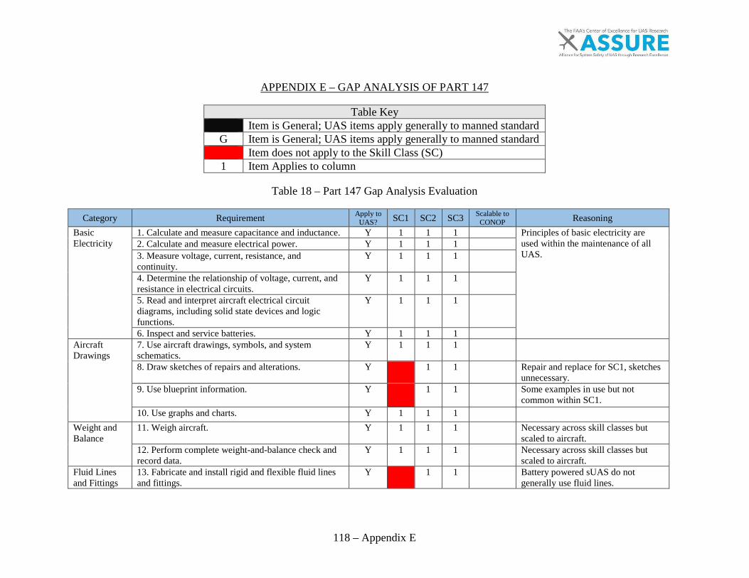
118 – Appendix E
APPENDIX E – GAP ANALYSIS OF PART 147
Table Key Item is General; UAS items apply generally to manned standard
G Item is General; UAS items apply generally to manned standard Item does not apply to the Skill Class (SC) 1 Item Applies to column
Table 18 – Part 147 Gap Analysis Evaluation
Category Requirement Apply to UAS? SC1 SC2 SC3 Scalable to
CONOP Reasoning Basic Electricity
1. Calculate and measure capacitance and inductance. Y 1 1 1
Principles of basic electricity are used within the maintenance of all UAS.
2. Calculate and measure electrical power. Y 1 1 1
3. Measure voltage, current, resistance, and continuity.
Y 1 1 1
4. Determine the relationship of voltage, current, and resistance in electrical circuits.
Y 1 1 1
5. Read and interpret aircraft electrical circuit diagrams, including solid state devices and logic functions.
Y 1 1 1
6. Inspect and service batteries. Y 1 1 1
Aircraft Drawings
7. Use aircraft drawings, symbols, and system schematics.
Y 1 1 1
8. Draw sketches of repairs and alterations. Y
1 1
Repair and replace for SC1, sketches unnecessary.
9. Use blueprint information. Y
1 1
Some examples in use but not common within SC1.
10. Use graphs and charts. Y 1 1 1
Weight and Balance
11. Weigh aircraft. Y 1 1 1
Necessary across skill classes but scaled to aircraft.
12. Perform complete weight-and-balance check and record data.
Y 1 1 1
Necessary across skill classes but scaled to aircraft.
Fluid Lines and Fittings
13. Fabricate and install rigid and flexible fluid lines and fittings.
Y
1 1
Battery powered sUAS do not generally use fluid lines.

119 – Appendix E
Category Requirement Apply to UAS? SC1 SC2 SC3 Scalable to
CONOP Reasoning Materials and Processes
14. Identify and select appropriate nondestructive testing methods.
Y 1 1 1
15. Perform dye penetrant, eddy current, ultrasonic, and magnetic particle inspections.
Y
1 1
Unnecessary and cost prohibitive for sUAS.
16. Perform basic heat-treating processes. Y
1
17. Identify and select aircraft hardware and materials. Y 1 1 1
18. Inspect and check welds. Y
1
Scaled to aircraft. 19. Perform precision measurements. Y 1 1 1
Ground Operation and Servicing
20. Start, ground operate, move, service, and secure aircraft and identify typical ground operation hazards.
Y 1 1 1
Scaled to aircraft.
21. Identify and select fuels. Y 1 1 1
Scaled to aircraft. Cleaning and Corrosion Control
22. Identify and select cleaning materials. Y 1 1 1
A clean aircraft will be more reliable. 23. Inspect, identify, remove, and treat aircraft corrosion and perform aircraft cleaning.
Y 1 1 1
Mathematics 24. Extract roots and raise numbers to a given power. Y 1 1 1
Basic math is necessary as a prerequisite to electronics. 25. Determine areas and volumes of various
geometrical shapes. Y 1 1 1
26. Solve ratio, proportion, and percentage problems. Y 1 1 1
27. Perform algebraic operations involving addition, subtraction, multiplication, and division of positive and negative numbers.
Y 1 1 1
Maintenance Forms and Records
28. Write descriptions of work performed including aircraft discrepancies and corrective actions using typical aircraft maintenance records.
Y 1 1 1
Typical AM records may not be used on sUAS. Though part 107 recommends record keeping it does not define the format of records.
29. Complete required maintenance forms, records, and inspection reports.
Y 1 1 1
All UAS operators and maintainers should keep accurate data.
Basic Physics 30. Use and understand the principles of simple machines; sound, fluid, and heat dynamics; basic aerodynamics; aircraft structures; and theory of flight.
Y 1 1 1
Basic physics is necessary to understand flight and aircraft characteristics. Addition of multirotor flight characteristics/control is warranted.

120 – Appendix E
Category Requirement Apply to UAS? SC1 SC2 SC3 Scalable to
CONOP Reasoning Maintenance Publications
31. Demonstrate ability to read, comprehend, and apply information contained in FAA and manufacturers' aircraft maintenance specifications, data sheets, manuals, publications, and related Federal Aviation Regulations, Airworthiness Directives, and Advisory material.
Y 1 1 1
Scaled to aircraft.
32. Read technical data. Y 1 1 1
Maintenance technician Privileges and Limitations
33. Exercise maintenance technician privileges within the limitations prescribed by part 65 of this chapter.
Y
1 1
As the industry sits today, AIRCRAFT maintenance technicians are typically sought on MALE/HALE systems. "Tactical" sized systems (RQ-7B, Etc.) see AIRCRAFT as a bonus but unnecessary to perform maintenance. sUAS sees AIRCRAFT as completely unnecessary.
Wood Structures
1. Service and repair wood structures. Y 1
Scaled to aircraft. 2. Identify wood defects. N
Y
3. Inspect wood structures. Y 1
Aircraft Covering
4. Select and apply fabric and fiberglass covering materials.
Y
1 1
Some applications re: foam but outside 147 scope.
5. Inspect, test, and repair fabric and fiberglass. Y 1 1 1
sUAS composites repair is rarely performed, by anyone other than the manufacturer. “Remove and replace” is most common on sUAS. However, non-destructive testing for defects should be done across the board.
Aircraft Finishes
6. Apply trim, letters, and touchup paint. Y
1 1
Need to include foam and associated processes.
7. Identify and select aircraft finishing materials. Y
1 1
Need to include foam and associated processes.
8. Apply finishing materials. Y
1 1
9. Inspect finishes and identify defects. Y
1 1
Sheet Metal and Non-Metallic Structures
10. Select, install, and remove special fasteners for metallic, bonded, and composite structures.
Y
1 1
Metallic structures would generally be used on optionally piloted aircraft and passenger UAS. Bonded and composite structures can be found throughout the UAS class structure.
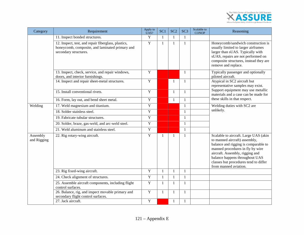
121 – Appendix E
Category Requirement Apply to UAS? SC1 SC2 SC3 Scalable to
CONOP Reasoning 11. Inspect bonded structures. Y 1 1 1
12. Inspect, test, and repair fiberglass, plastics, honeycomb, composite, and laminated primary and secondary structures.
Y 1 1 1
Honeycomb/sandwich construction is usually limited to larger airframes larger than sUAS. Typically with sUAS, repairs are not performed on composite structures, instead they are remove and replace.
13. Inspect, check, service, and repair windows, doors, and interior furnishings.
Y
1
Typically passenger and optionally piloted aircraft.
14. Inspect and repair sheet-metal structures. Y
1 1
Atypical in SC2 aircraft but representative samples may exist. Support equipment may use metallic materials and a case can be made for these skills in that respect.
15. Install conventional rivets. Y
1 1
16. Form, lay out, and bend sheet metal. Y
1 1
Welding 17. Weld magnesium and titanium. Y
1
Welding duties with SC2 are unlikely. 18. Solder stainless steel. Y
1
19. Fabricate tubular structures. Y
1
20. Solder, braze, gas-weld, and arc-weld steel. Y
1
21. Weld aluminum and stainless steel. Y
1
Assembly and Rigging
22. Rig rotary-wing aircraft. Y 1 1 1
Scalable to aircraft. Large UAS (akin to manned aircraft) assembly, balance and rigging is comparable to manned procedures in fly by wire aircraft. Assembly, rigging and balance happens throughout UAS classes but procedures tend to differ from manned aviation.
23. Rig fixed-wing aircraft. Y 1 1 1
24. Check alignment of structures. Y 1 1 1
25. Assemble aircraft components, including flight control surfaces.
Y 1 1 1
26. Balance, rig, and inspect movable primary and secondary flight control surfaces.
Y 1 1 1
27. Jack aircraft. Y
1 1
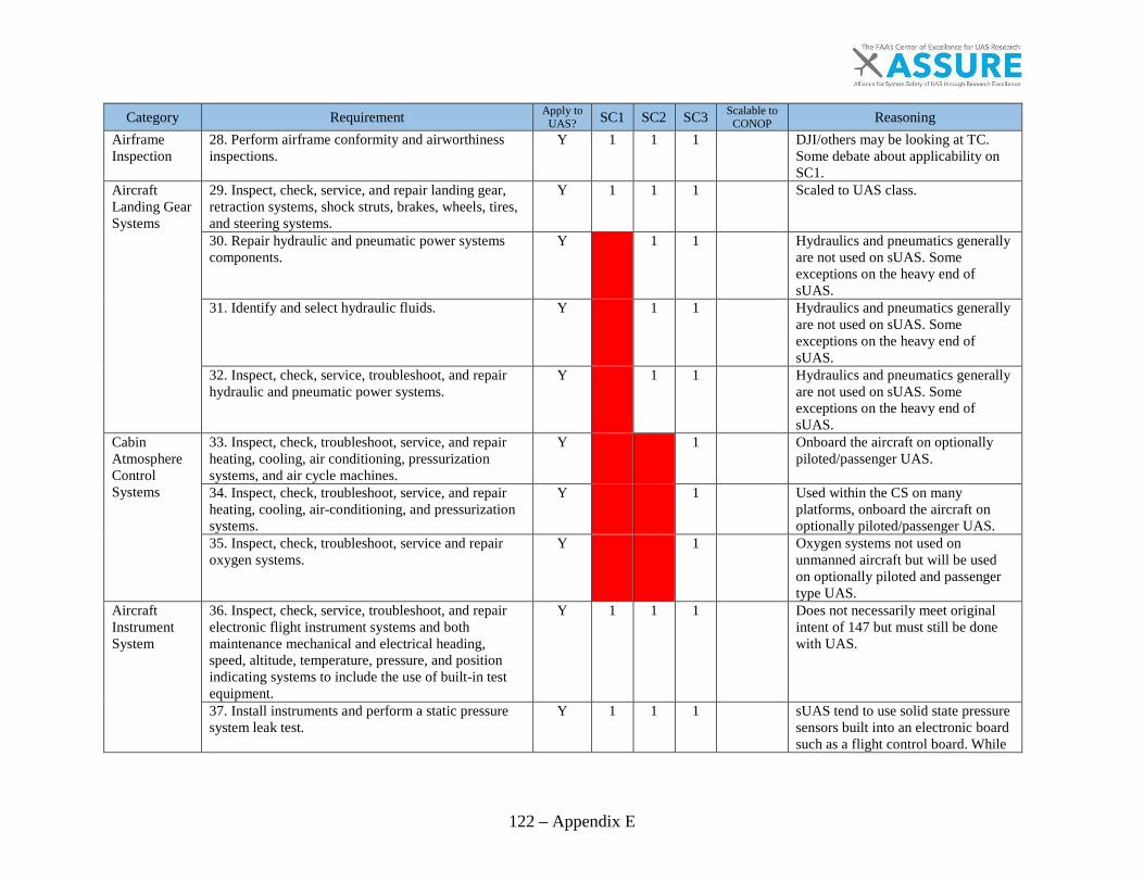
122 – Appendix E
Category Requirement Apply to UAS? SC1 SC2 SC3 Scalable to
CONOP Reasoning Airframe Inspection
28. Perform airframe conformity and airworthiness inspections.
Y 1 1 1
DJI/others may be looking at TC. Some debate about applicability on SC1.
Aircraft Landing Gear Systems
29. Inspect, check, service, and repair landing gear, retraction systems, shock struts, brakes, wheels, tires, and steering systems.
Y 1 1 1
Scaled to UAS class.
30. Repair hydraulic and pneumatic power systems components.
Y
1 1
Hydraulics and pneumatics generally are not used on sUAS. Some exceptions on the heavy end of sUAS.
31. Identify and select hydraulic fluids. Y
1 1
Hydraulics and pneumatics generally are not used on sUAS. Some exceptions on the heavy end of sUAS.
32. Inspect, check, service, troubleshoot, and repair hydraulic and pneumatic power systems.
Y
1 1
Hydraulics and pneumatics generally are not used on sUAS. Some exceptions on the heavy end of sUAS.
Cabin Atmosphere Control Systems
33. Inspect, check, troubleshoot, service, and repair heating, cooling, air conditioning, pressurization systems, and air cycle machines.
Y
1
Onboard the aircraft on optionally piloted/passenger UAS.
34. Inspect, check, troubleshoot, service, and repair heating, cooling, air-conditioning, and pressurization systems.
Y
1
Used within the CS on many platforms, onboard the aircraft on optionally piloted/passenger UAS.
35. Inspect, check, troubleshoot, service and repair oxygen systems.
Y
1
Oxygen systems not used on unmanned aircraft but will be used on optionally piloted and passenger type UAS.
Aircraft Instrument System
36. Inspect, check, service, troubleshoot, and repair electronic flight instrument systems and both maintenance mechanical and electrical heading, speed, altitude, temperature, pressure, and position indicating systems to include the use of built-in test equipment.
Y 1 1 1
Does not necessarily meet original intent of 147 but must still be done with UAS.
37. Install instruments and perform a static pressure system leak test.
Y 1 1 1
sUAS tend to use solid state pressure sensors built into an electronic board such as a flight control board. While
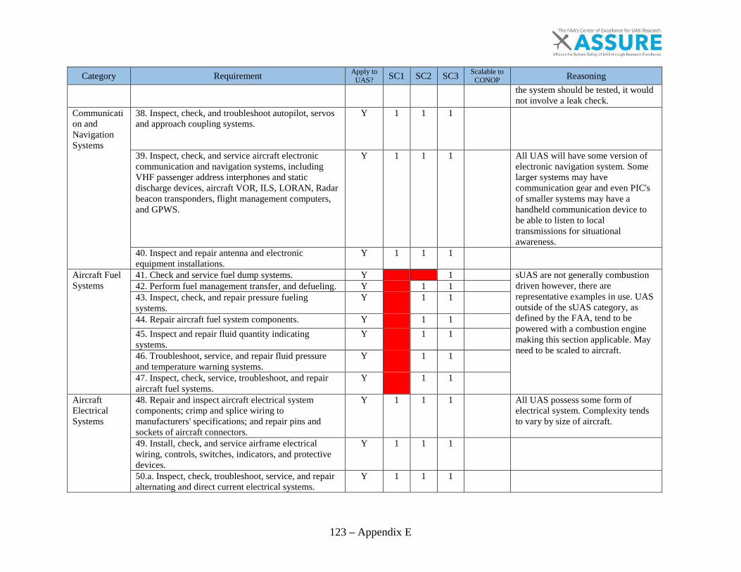
123 – Appendix E
Category Requirement Apply to UAS? SC1 SC2 SC3 Scalable to
CONOP Reasoning the system should be tested, it would not involve a leak check.
Communication and Navigation Systems
38. Inspect, check, and troubleshoot autopilot, servos and approach coupling systems.
Y 1 1 1
39. Inspect, check, and service aircraft electronic communication and navigation systems, including VHF passenger address interphones and static discharge devices, aircraft VOR, ILS, LORAN, Radar beacon transponders, flight management computers, and GPWS.
Y 1 1 1
All UAS will have some version of electronic navigation system. Some larger systems may have communication gear and even PIC's of smaller systems may have a handheld communication device to be able to listen to local transmissions for situational awareness.
40. Inspect and repair antenna and electronic equipment installations.
Y 1 1 1
Aircraft Fuel Systems
41. Check and service fuel dump systems. Y
1
sUAS are not generally combustion driven however, there are representative examples in use. UAS outside of the sUAS category, as defined by the FAA, tend to be powered with a combustion engine making this section applicable. May need to be scaled to aircraft.
42. Perform fuel management transfer, and defueling. Y
1 1
43. Inspect, check, and repair pressure fueling systems.
Y
1 1
44. Repair aircraft fuel system components. Y
1 1
45. Inspect and repair fluid quantity indicating systems.
Y
1 1
46. Troubleshoot, service, and repair fluid pressure and temperature warning systems.
Y
1 1
47. Inspect, check, service, troubleshoot, and repair aircraft fuel systems.
Y
1 1
Aircraft Electrical Systems
48. Repair and inspect aircraft electrical system components; crimp and splice wiring to manufacturers' specifications; and repair pins and sockets of aircraft connectors.
Y 1 1 1
All UAS possess some form of electrical system. Complexity tends to vary by size of aircraft.
49. Install, check, and service airframe electrical wiring, controls, switches, indicators, and protective devices.
Y 1 1 1
50.a. Inspect, check, troubleshoot, service, and repair alternating and direct current electrical systems.
Y 1 1 1

124 – Appendix E
Category Requirement Apply to UAS? SC1 SC2 SC3 Scalable to
CONOP Reasoning 50.b. Inspect, check, and troubleshoot constant speedand integrated speed drive generators.
Y 1
Position and Warning Systems
51. Inspect, check, and service speed andconfiguration warning systems, electrical brakecontrols, and anti-skid systems.
Y 1 1 1 Scalable to aircraft with SC1 using speed and configuration warnings. SC2 do include braking systems in some systems.
52. Inspect, check, troubleshoot, and service landinggear position indicating and warning systems.
Y 1 Although examples of moveable/foldable landing gear can be found within any class of UAS, systems smaller than manned aircraft tend to have fixed landing systems or alternate landing systems such as net recovery or belly skid recovery.
Ice and Rain Control Systems
53. Inspect, check, troubleshoot, service, and repairairframe ice and rain control systems.
Y 1 Standard operating procedure for most systems is to completely avoid icing conditions.
Fire Protection Systems
54. Inspect, check, and service smoke and carbonmonoxide detection systems.
y 1 Smoke and carbon monoxide systems are unnecessary on UAS that do not carry passengers/crew.
55. Inspect, check, service, troubleshoot, and repairaircraft fire detection and extinguishing systems.
Y 1
Reciprocating Engines
1. Inspect and repair a radial engine. N Y Scaled for sUAS, not generally used but representative examples exist.
2. Overhaul reciprocating engine. Y 1 1 Scaled to sUAS. Not generally used on sUAS however near the 55lbs. cutoff, they are in use. Generally with aircraft designed for military or dual use as defined in Task 1.
3. Inspect, check, service, and repair reciprocatingengines and engine installations.
Y 1 1
4. Install, troubleshoot, and remove reciprocatingengines.
Y 1 1
Turbine Engines
5. Overhaul turbine engine. Y 1 Scaled for sUAS 6. Inspect, check, service, and repair turbine enginesand turbine engine installations.
Y 1 While turbine engines are being made small enough for sUAS, I have been unable to find examples of their use. Large UAS such as the Global Hawk or Avenger aircraft do use turbine engines.
7. Install, troubleshoot, and remove turbine engines. Y 1

125 – Appendix E
Category Requirement Apply to UAS? SC1 SC2 SC3 Scalable to
CONOP Reasoning Engine Inspection
8. Perform powerplant conformity and air worthiness inspections.
Y 1 1 1
Intent is to cover any power generation source for the aircraft.
Engine Instrument Systems
9. Troubleshoot, service, and repair electrical and maintenance mechanical fluid rate-of-flow indicating systems.
Y
1 1
Limited to liquid fuel systems and sprayer systems.
10. Inspect, check, service, troubleshoot, and repair electrical and maintenance mechanical engine temperature, pressure, and r.p.m. indicating systems.
Y
1 1
sUAS typically have these systems built into a circuit board sometimes the same board as the flight controller but not always. Checks are possible (usually done in pre-flight) but extensive t-shoot or servicing is not required as they are generally remove and replace.
Engine Fire Protection Systems
11. Inspect, check, service, troubleshoot, and repair engine fire detection and extinguishing systems.
Y
1
Engine Electrical Systems
12. Repair engine electrical system components. Y 1 1 1
Engine electrical systems with most sUAS are simple systems consisting of electric motors, PDBs and ESCs. Outside of calibration of the ESCs and R&R no repairs are typically done. Exception: sUAS with liquid fuel engines and some form of alternator or DC generator. Scalable to aircraft SC1.
13. Install, check, and service engine electrical wiring, controls, switches, indicators, and protective devices.
Y 1 1 1
If using "engine" and "motor" interchangeably all UAS possess some kind of wiring and controls to or from the engine/motor. This can be scaled back from the manned maintainer standard with UAS utilizing small engines or electrical motors.
Lubrications Systems
14. Identify and select lubricants. Y
1 1
Can be applicable to UAS with engines. DC motors are not lubed.
15. Repair engine lubrication system components. Y
1 1
16. Inspect, check, service, troubleshoot, and repair engine lubrication systems.
Y
1 1

126 – Appendix E
Category Requirement Apply to UAS? SC1 SC2 SC3 Scalable to
CONOP Reasoning Ignition and starting systems
17. Overhaul magneto and ignition harness. Y
1 1
Magnetos not typically used on UAS smaller manned aircraft. Internal combustion engines can use some form of ignition wiring harness but on systems smaller than manned. aircraft, starting systems tend to be external.
18. Inspect, service, troubleshoot, and repair reciprocating and turbine engine ignition systems and components.
Y
1 1
Limited to UAS using combustion engines. Typically at the higher end of sUAS and larger.
19.a. Inspect, service, troubleshoot, and repair turbine engine electrical starting systems.
Y
1
As stated above turbine engines are only typically used on large UAS HALE/MALE/optionally piloted/passenger.
19.b. Inspect, service, and troubleshoot turbine engine pneumatic starting systems.
Y
1
Fuel Metering Systems
20. Troubleshoot and adjust turbine engine fuel metering systems and electronic engine fuel controls.
Y
1
Limited to UAS using turbine engines. Typically SC3.
21. Overhaul carburetor. Y
1 1
Limited to UAS using combustion engines. Typically at the higher end of sUAS and larger.
22. Repair engine fuel metering system components. Y
1 1
Limited to UAS using combustion engines. Typically at the higher end of sUAS and larger.
23. Inspect, check, service, troubleshoot, and repair reciprocating and turbine engine fuel metering systems.
Y
1 1
Limited to UAS using combustion engines. Typically at the higher end of sUAS and larger.
Engine Fuel Systems
24. Repair engine fuel system components. Y
1 1
Limited to UAS using combustion engines. Typically at the higher end of sUAS and larger.
25. Inspect, check, service, troubleshoot, and repair engine fuel systems.
Y
1 1
Limited to UAS using combustion engines. Typically at the higher end of sUAS and larger.
Induction and Engine Airflow Systems
26. Inspect, check, troubleshoot, service, and repair engine ice and rain control systems.
Y
1
Some examples of "tactical" sized UAS using heated carburetors to prevent engine icing. More ice and rain control systems tend be installed

127 – Appendix E
Category Requirement Apply to UAS? SC1 SC2 SC3 Scalable to
CONOP Reasoning on larger MALE/HALE/optionally piloted/passenger UAS.
27. Inspect, check, service, troubleshoot and repair heat exchangers, superchargers, and turbine engine airflow and temperature control systems.
Y
1
28. Inspect, check, service, and repair carburetor air intake and induction manifolds.
Y
1 1
Engine Cooling Systems
29. Repair engine cooling system components. Y
1
Most liquid fueled UAS use air-cooling systems for their engines. Some of the larger/more complex systems may use cooling devices for engine oil to help keep engine temperatures low.
30. Inspect, check, troubleshoot, service, and repair engine cooling systems.
Y
1
See above.
Engine Exhaust and Reverser Systems
31. Repair engine exhaust system components. Y
1 1
Remove and replace typical in SC2.
32.a. Inspect, check, troubleshoot, service, and repair engine exhaust systems.
Y
1 1
32.b. Troubleshoot and repair engine thrust reverser systems and related components.
Y
1
Rare on UAS; Large turbine equipped UAS may utilize.
Propellors 33. Inspect, check, service, and repair propeller synchronizing and ice control systems.
Y
1
Prop sync systems are only used on multi engine UAS, which tend to be large/extended range. Ice control systems also tend to only be used on Large UAS. Most SC 1 and SC2 UAS avoid icing conditions allowing them to save the weight of sealing the aircraft and incorporating anti icing systems.
34. Identify and select propeller lubricants. Y
1
Typically involves a variable pitch prop which is rare to see in use with sUAS. However, there is a lot of research and development focused on this for larger than sUAS.

128 – Appendix E
Category Requirement Apply to UAS? SC1 SC2 SC3 Scalable to
CONOP Reasoning 35. Balance propellers. Y 1 1 1
36. Repair propeller control system components. Y
1
37. Inspect, check, service, and repair fixed-pitch, constant-speed, and feathering propellers, and propeller governing systems.
Y
1 1
Small-medium UAS tend to remove and replace props with damage. They also tend to be fixed props, although variable pitch props can be used. All UAS require inspect and check procedures for props. All SC should inspect and check propellers, scalable to Aircraft.
38. Install, troubleshoot, and remove propellers. Y 1 1 1
Scaled to SC. 39. Repair aluminum alloy propeller blades. Y
1
Plastic, carbon fiber and wood blades tend to be used for small-medium UAS. Aircraft comparable to manned (RQ-9) uses aluminum props. Possibility of use within SC1/SC2 but not regularly done.
Unducted Fans
40. Inspect and troubleshoot unducted fan systems and components.
N
Unducted fan systems are not used in manned or unmanned aviation.
Auxiliary Power Units
41. Inspect, check, service, and troubleshoot turbine-driven auxiliary power units.
Y
1
Due to the weight, turbine driven APU's are limited to large aircraft.
Total out of 131
52 93 127
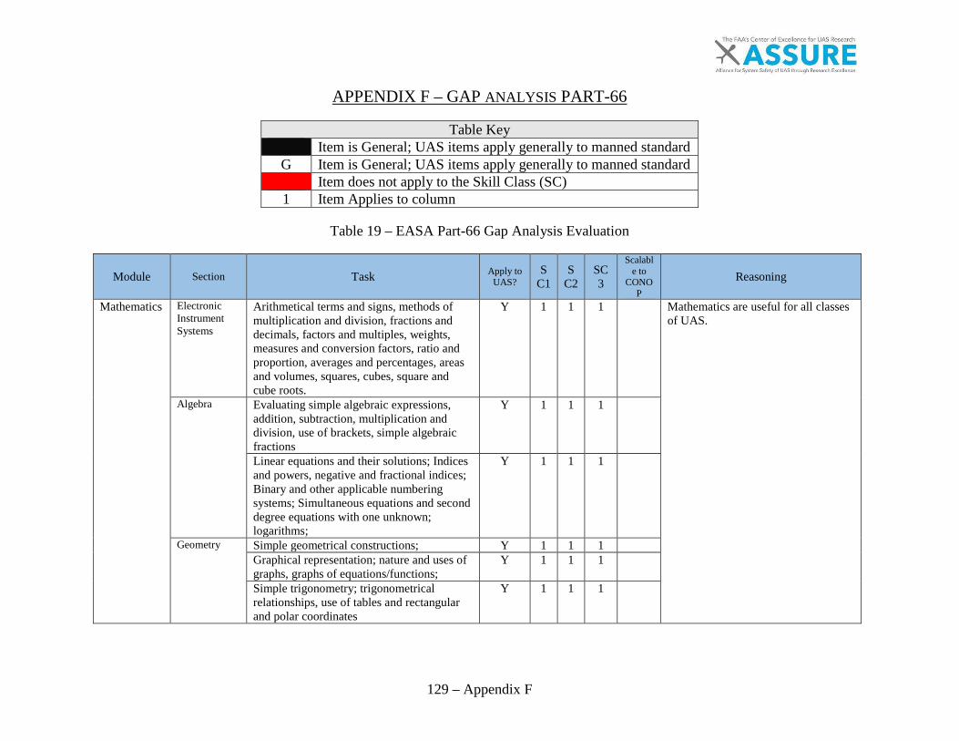
129 – Appendix F
APPENDIX F – GAP ANALYSIS PART-66
Table Key Item is General; UAS items apply generally to manned standard
G Item is General; UAS items apply generally to manned standard Item does not apply to the Skill Class (SC) 1 Item Applies to column
Table 19 – EASA Part-66 Gap Analysis Evaluation
Module Section Task Apply to UAS?
SC1
SC2
SC3
Scalable to
CONOP
Reasoning
Mathematics Electronic Instrument Systems
Arithmetical terms and signs, methods of multiplication and division, fractions and decimals, factors and multiples, weights, measures and conversion factors, ratio and proportion, averages and percentages, areas and volumes, squares, cubes, square and cube roots.
Y 1 1 1
Mathematics are useful for all classes of UAS.
Algebra Evaluating simple algebraic expressions, addition, subtraction, multiplication and division, use of brackets, simple algebraic fractions
Y 1 1 1
Linear equations and their solutions; Indices and powers, negative and fractional indices; Binary and other applicable numbering systems; Simultaneous equations and second degree equations with one unknown; logarithms;
Y 1 1 1
Geometry Simple geometrical constructions; Y 1 1 1
Graphical representation; nature and uses of graphs, graphs of equations/functions;
Y 1 1 1
Simple trigonometry; trigonometrical relationships, use of tables and rectangular and polar coordinates
Y 1 1 1
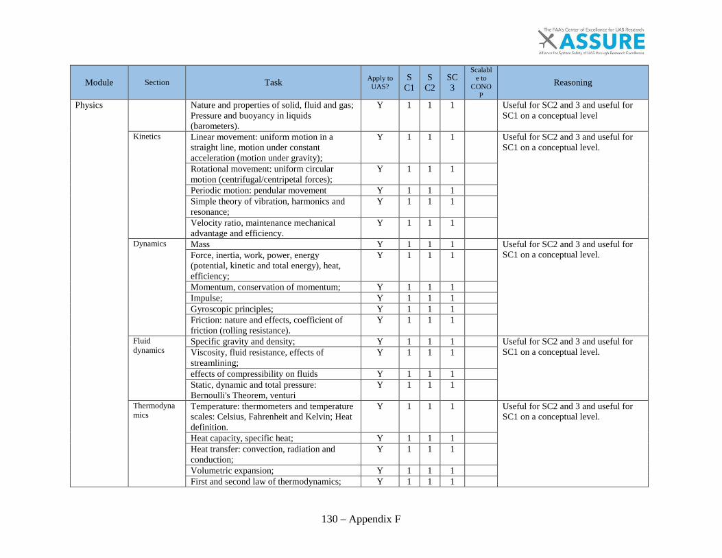
130 – Appendix F
Module Section Task Apply to UAS?
SC1
SC2
SC3
Scalable to
CONOP
Reasoning
Physics Nature and properties of solid, fluid and gas; Pressure and buoyancy in liquids (barometers).
Y 1 1 1
Useful for SC2 and 3 and useful for SC1 on a conceptual level
Kinetics Linear movement: uniform motion in a straight line, motion under constant acceleration (motion under gravity);
Y 1 1 1
Useful for SC2 and 3 and useful for SC1 on a conceptual level.
Rotational movement: uniform circular motion (centrifugal/centripetal forces);
Y 1 1 1
Periodic motion: pendular movement Y 1 1 1
Simple theory of vibration, harmonics and resonance;
Y 1 1 1
Velocity ratio, maintenance mechanical advantage and efficiency.
Y 1 1 1
Dynamics Mass Y 1 1 1
Useful for SC2 and 3 and useful for SC1 on a conceptual level.
Force, inertia, work, power, energy (potential, kinetic and total energy), heat, efficiency;
Y 1 1 1
Momentum, conservation of momentum; Y 1 1 1
Impulse; Y 1 1 1
Gyroscopic principles; Y 1 1 1
Friction: nature and effects, coefficient of friction (rolling resistance).
Y 1 1 1
Fluid dynamics
Specific gravity and density; Y 1 1 1
Useful for SC2 and 3 and useful for SC1 on a conceptual level.
Viscosity, fluid resistance, effects of streamlining;
Y 1 1 1
effects of compressibility on fluids Y 1 1 1
Static, dynamic and total pressure: Bernoulli's Theorem, venturi
Y 1 1 1
Thermodynamics
Temperature: thermometers and temperature scales: Celsius, Fahrenheit and Kelvin; Heat definition.
Y 1 1 1
Useful for SC2 and 3 and useful for SC1 on a conceptual level.
Heat capacity, specific heat; Y 1 1 1
Heat transfer: convection, radiation and conduction;
Y 1 1 1
Volumetric expansion; Y 1 1 1
First and second law of thermodynamics; Y 1 1 1

131 – Appendix F
Module Section Task Apply to UAS?
SC1
SC2
SC3
Scalable to
CONOP
Reasoning
Gases: ideal gases laws; specific heat at constant volume and constant pressure, work done by expanding gas;
Y 1 1 1
Isothermal, adiabatic expansion and compression, engine cycles, constant volume and constant pressure, refrigerators and heat pumps;
Y 1 1 1
Latent heats of fusion and evaporation, thermal energy, heat of combustion.
Y 1 1 1
Optics (Light) Nature of light; speed of light; Y 1 1 1
Useful for SC2 and 3 and useful for SC1 on a conceptual level.
Laws of reflection and refraction: reflection at plane surfaces, reflection by spherical mirrors, refraction, lenses;
Y 1 1 1
Fibre optics. Y 1 1 1
Wave Motion and Sound
Wave motion: maintenance mechanical waves, sinusoidal wave motion, interference phenomena, standing waves;
Y 1 1 1
Useful for SC2 and 3 and useful for SC1 on a conceptual level.
Sound: speed of sound, production of sound, intensity, pitch and quality, Doppler effect
Y 1 1 1
Electrical Fundamentals
Electron Theory
Structure and distribution of electrical charges within: atoms, molecules, ions, compounds;
Y 1 1 1
Useful for SC2 and 3 and useful for SC1 on a conceptual level.
Molecular structure of conductors, semiconductors and insulators.
Y 1 1 1
Static Electricity and Conduction
Static electricity and distribution of electrostatic charges
Y 1 1 1
Basic electrical knowledge is important on all UAS as they are electronics heavy.
Electrostatic laws of attraction and repulsion; Y 1 1 1
Units of charge, Coulomb's Law; Y 1 1 1
Conduction of electricity in solids, liquids, gases and a vacuum.
Y 1 1 1
Electrical Terminology
The following terms, their units and factors affecting them: potential difference, electromotive force, voltage, current, resistance, conductance, charge, conventional current flow, electron flow.
Y 1 1 1
Basic electrical knowledge is important on all UAS as they are electronics heavy.
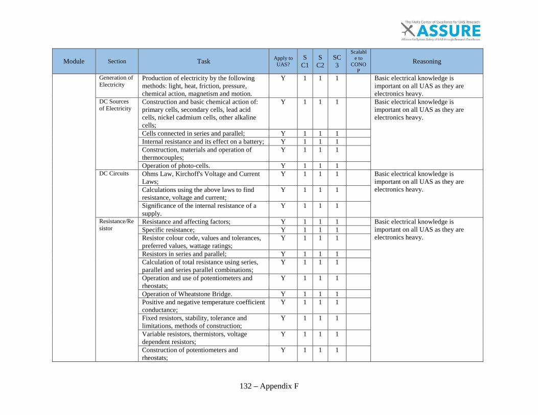
132 – Appendix F
Module Section Task Apply to UAS?
SC1
SC2
SC3
Scalable to
CONOP
Reasoning
Generation of Electricity
Production of electricity by the following methods: light, heat, friction, pressure, chemical action, magnetism and motion.
Y 1 1 1
Basic electrical knowledge is important on all UAS as they are electronics heavy.
DC Sources of Electricity
Construction and basic chemical action of: primary cells, secondary cells, lead acid cells, nickel cadmium cells, other alkaline cells;
Y 1 1 1
Basic electrical knowledge is important on all UAS as they are electronics heavy.
Cells connected in series and parallel; Y 1 1 1
Internal resistance and its effect on a battery; Y 1 1 1
Construction, materials and operation of thermocouples;
Y 1 1 1
Operation of photo-cells. Y 1 1 1
DC Circuits Ohms Law, Kirchoff's Voltage and Current Laws;
Y 1 1 1
Basic electrical knowledge is important on all UAS as they are electronics heavy.
Calculations using the above laws to find resistance, voltage and current;
Y 1 1 1
Significance of the internal resistance of a supply.
Y 1 1 1
Resistance/Resistor
Resistance and affecting factors; Y 1 1 1
Basic electrical knowledge is important on all UAS as they are electronics heavy.
Specific resistance; Y 1 1 1
Resistor colour code, values and tolerances, preferred values, wattage ratings;
Y 1 1 1
Resistors in series and parallel; Y 1 1 1
Calculation of total resistance using series, parallel and series parallel combinations;
Y 1 1 1
Operation and use of potentiometers and rheostats;
Y 1 1 1
Operation of Wheatstone Bridge. Y 1 1 1
Positive and negative temperature coefficient conductance;
Y 1 1 1
Fixed resistors, stability, tolerance and limitations, methods of construction;
Y 1 1 1
Variable resistors, thermistors, voltage dependent resistors;
Y 1 1 1
Construction of potentiometers and rheostats;
Y 1 1 1

133 – Appendix F
Module Section Task Apply to UAS?
SC1
SC2
SC3
Scalable to
CONOP
Reasoning
Construction of Wheatstone Bridge; Y 1 1 1
Power Power, work and energy (kinetic and potential);
Y 1 1 1
Basic electrical knowledge is important on all UAS as they are electronics heavy.
Dissipation of power by a resistor; Y 1 1 1
Power formula; Y 1 1 1
Calculations involving power, work and energy.
Y 1 1 1
Capacitance/Capacitor
Operation and function of a capacitor; Y 1 1 1
Basic electrical knowledge is important on all UAS as they are electronics heavy.
Factors affecting capacitance area of plates, distance between plates, number of plates, dielectric and dielectric constant, working voltage, voltage rating;
Y 1 1 1
Capacitor types, construction and function; Y 1 1 1
Capacitor colour coding; Y 1 1 1
Calculations of capacitance and voltage in series and parallel circuits;
Y 1 1 1
Exponential charge and discharge of a capacitor, time constants;
Y 1 1 1
Testing of capacitors. Y 1 1 1
Magnetism Theory of magnetism; Y 1 1 1
Basic electrical knowledge is important on all UAS as they are electronics heavy.
Properties of a magnet; Y 1 1 1
Action of a magnet suspended in the Earth's magnetic field;
Y 1 1 1
Magnetisation and demagnetisation; Y 1 1 1
Magnetic shielding; Y 1 1 1
Various types of magnetic material; Y 1 1 1
Electromagnets construction and principles of operation;
Y 1 1 1
Hand clasp rules to determine: magnetic field around current carrying conductor.
Y 1 1 1
Magnetomotive force, field strength, magnetic flux density, permeability, hysteresis loop, retentivity, coercive force reluctance, saturation point, eddy currents;
Y 1 1 1
Precautions for care and storage of magnets. Y 1 1 1
Faraday's Law; Y 1 1 1
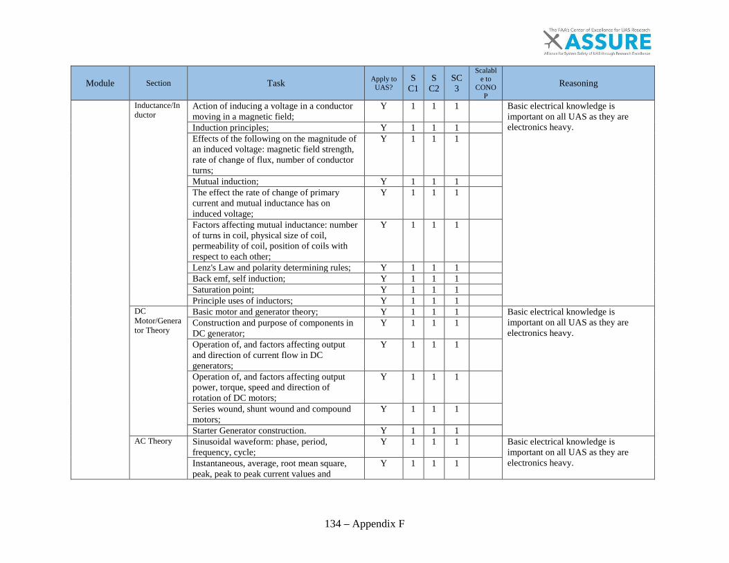
134 – Appendix F
Module Section Task Apply to UAS?
SC1
SC2
SC3
Scalable to
CONOP
Reasoning
Inductance/Inductor
Action of inducing a voltage in a conductor moving in a magnetic field;
Y 1 1 1
Basic electrical knowledge is important on all UAS as they are electronics heavy.
Induction principles; Y 1 1 1
Effects of the following on the magnitude of an induced voltage: magnetic field strength, rate of change of flux, number of conductor turns;
Y 1 1 1
Mutual induction; Y 1 1 1
The effect the rate of change of primary current and mutual inductance has on induced voltage;
Y 1 1 1
Factors affecting mutual inductance: number of turns in coil, physical size of coil, permeability of coil, position of coils with respect to each other;
Y 1 1 1
Lenz's Law and polarity determining rules; Y 1 1 1
Back emf, self induction; Y 1 1 1
Saturation point; Y 1 1 1
Principle uses of inductors; Y 1 1 1
DC Motor/Generator Theory
Basic motor and generator theory; Y 1 1 1
Basic electrical knowledge is important on all UAS as they are electronics heavy.
Construction and purpose of components in DC generator;
Y 1 1 1
Operation of, and factors affecting output and direction of current flow in DC generators;
Y 1 1 1
Operation of, and factors affecting output power, torque, speed and direction of rotation of DC motors;
Y 1 1 1
Series wound, shunt wound and compound motors;
Y 1 1 1
Starter Generator construction. Y 1 1 1
AC Theory Sinusoidal waveform: phase, period, frequency, cycle;
Y 1 1 1
Basic electrical knowledge is important on all UAS as they are electronics heavy.
Instantaneous, average, root mean square, peak, peak to peak current values and
Y 1 1 1

135 – Appendix F
Module Section Task Apply to UAS?
SC1
SC2
SC3
Scalable to
CONOP
Reasoning
calculations of these values, in relation to voltage, current and power Triangular/Square waves; Y 1 1 1
Single/3 phase principles. Y 1 1 1
Resistive (R), Capacitive (C) and Inductive (L) Circuits
Phase relationship of voltage and current in L, C and R circuits, parallel, series and series parallel
Y 1 1 1
Basic electrical knowledge is important on all UAS as they are electronics heavy. Power dissipation in L, C and R circuits; Y 1 1 1
Impedance, phase angle, power factor and current calculations;
Y 1 1 1
True power, apparent power and reactive power calculations
Y 1 1 1
Transformers Transformer construction principles and operation;
Y 1 1 1
Basic electrical knowledge is important on all UAS as they are electronics heavy.
Transformer losses and methods for overcoming them;
Y 1 1 1
Transformer action under load and no-load conditions;
Y 1 1 1
Power transfer, efficiency, polarity markings;
Y 1 1 1
Calculation of line and phase voltages and currents;
Y 1 1 1
Calculation of power in a three phase system;
Y 1 1 1
Primary and Secondary current, voltage, turns ratio, power, efficiency;
Y 1 1 1
Auto transformers Y 1 1 1
Filters Operation, application and uses of the following filters: low pass, high pass, band pass, band stop.
Y 1 1 1
Basic electrical knowledge is important on all UAS as they are electronics heavy.
AC Generators
Rotation of loop in a magnetic field and waveform produced;
Y 1 1 1
Basic electrical knowledge is important on all UAS as they are electronics heavy.
Operation and construction of revolving armature and revolving field type AC generators;
Y 1 1 1
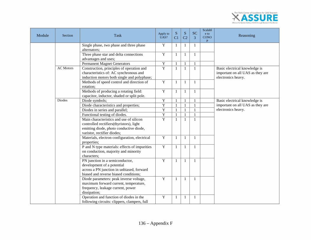
136 – Appendix F
Module Section Task Apply to UAS?
SC1
SC2
SC3
Scalable to
CONOP
Reasoning
Single phase, two phase and three phase alternators;
Y 1 1 1
Three phase star and delta connections advantages and uses;
Y 1 1 1
Permanent Magnet Generators Y 1 1 1
AC Motors Construction, principles of operation and characteristics of: AC synchronous and induction motors both single and polyphase;
Y 1 1 1
Basic electrical knowledge is important on all UAS as they are electronics heavy. Methods of speed control and direction of
rotation; Y 1 1 1
Methods of producing a rotating field: capacitor, inductor, shaded or split pole.
Y 1 1 1
Diodes Diode symbols; Y 1 1 1
Basic electrical knowledge is important on all UAS as they are electronics heavy.
Diode characteristics and properties; Y 1 1 1
Diodes in series and parallel; Y 1 1 1
Functional testing of diodes. Y 1 1 1
Main characteristics and use of silicon controlled rectifiers(thyristors), light emitting diode, photo conductive diode, varistor, rectifier diodes;
Y 1 1 1
Materials, electron configuration, electrical properties;
Y 1 1 1
P and N type materials: effects of impurities on conduction, majority and minority characters;
Y 1 1 1
PN junction in a semiconductor, development of a potential across a PN junction in unbiased, forward biased and reverse biased conditions;
Y 1 1 1
Diode parameters: peak inverse voltage, maximum forward current, temperature, frequency, leakage current, power dissipation;
Y 1 1 1
Operation and function of diodes in the following circuits: clippers, clampers, full
Y 1 1 1

137 – Appendix F
Module Section Task Apply to UAS?
SC1
SC2
SC3
Scalable to
CONOP
Reasoning
and half wave rectifiers, bridge rectifiers, voltage doublers and triplers; Detailed operation and characteristics of the following devices: silicon controlled rectifier (thyristor), light emitting diode, Shottky diode, photo conductive diode, varactor diode, varistor, rectifier diodes, Zener diode.
Y 1 1 1
Transistors Transistor symbols; Y 1 1 1
Basic electrical knowledge is important on all UAS as they are electronics heavy.
Component description and orientation; Y 1 1 1
Transistor characteristics and properties. Y 1 1 1
Construction and operation of PNP and NPN transistors;
Y 1 1 1
Base, collector and emitter configurations; Y 1 1 1
Testing of transistors Y 1 1 1
Basic appreciation of other transistor types and their uses.
Y 1 1 1
Application of transistors: classes of amplifier (A, B, C);
Y 1 1 1
Simple circuits including: bias, decoupling, feedback and stabilisation;
Y 1 1 1
Multistage circuit principles: cascades, push-pull, oscillators, multivibrators, flip-flop circuits.
Y 1 1 1
Integrated Circuits
Description and operation of logic circuits and linear circuits/operational amplifiers.
Y 1 1 1
Basic electrical knowledge is important on all UAS as they are electronics heavy. Description and operation of logic circuits
and linear circuits; Y 1 1 1
Introduction to operation and function of an operational amplifier used as: integrator, differentiator, voltage follower, comparator;
Y 1 1 1
Operation and amplifier stages connecting methods: resistive capacitive, inductive (transformer), inductive resistive (IR), direct;
Y 1 1 1
Advantages and disadvantages of positive and negative feedback.
Y 1 1 1

138 – Appendix F
Module Section Task Apply to UAS?
SC1
SC2
SC3
Scalable to
CONOP
Reasoning
Printed Circuit Boards
Description and use of printed circuit boards. Y 1 1 1
Basic electrical knowledge is important on all UAS as they are electronics heavy.
Servomechanisms
Understanding of the following terms: Open and closed loop systems, feedback, follow up, analogue transducers;
Y 1 1 1
Basic electrical knowledge is important on all UAS as they are electronics heavy. Principles of operation and use of the
following synchro system components/ features: resolvers, differential, control and torque, transformers, inductance and capacitance transmitters.
Y 1 1 1
Understanding of the following terms: Open and closed loop, follow up, servomechanism, analogue, transducer, null, damping, feedback, deadband;
Y 1 1 1
Construction operation and use of the following synchro system components: resolvers, differential, control and torque, E and I transformers, inductance transmitters, capacitance transmitters, synchronous transmitters
Y 1 1 1
Servomechanism defects, reversal of synchro leads, hunting.
Y 1 1 1
Digital Techniques Electronic Instrument Systems
Electronic Instrument Systems
Typical systems arrangements and cockpit layout of electronic instrument systems.
Y 1 1 1
Would have to be reworded to apply to CS.
Numbering Systems
Numbering systems: binary, octal and hexadecimal;
Y 1 1 1
Useful at a conceptual level.
Demonstration of conversions between the decimal and binary, octal and hexadecimal systems and vice versa.
Y 1 1 1
Useful at a conceptual level.
Data Conversion
Analogue Data, Digital Data; Y
1 1
Concepts may be unnecessary, as most SC1 are remove and replace.
Operation and application of analogue to digital, and digital to analogue converters,
Y
1 1
Concepts may be unnecessary, as most SC1 are remove and replace.
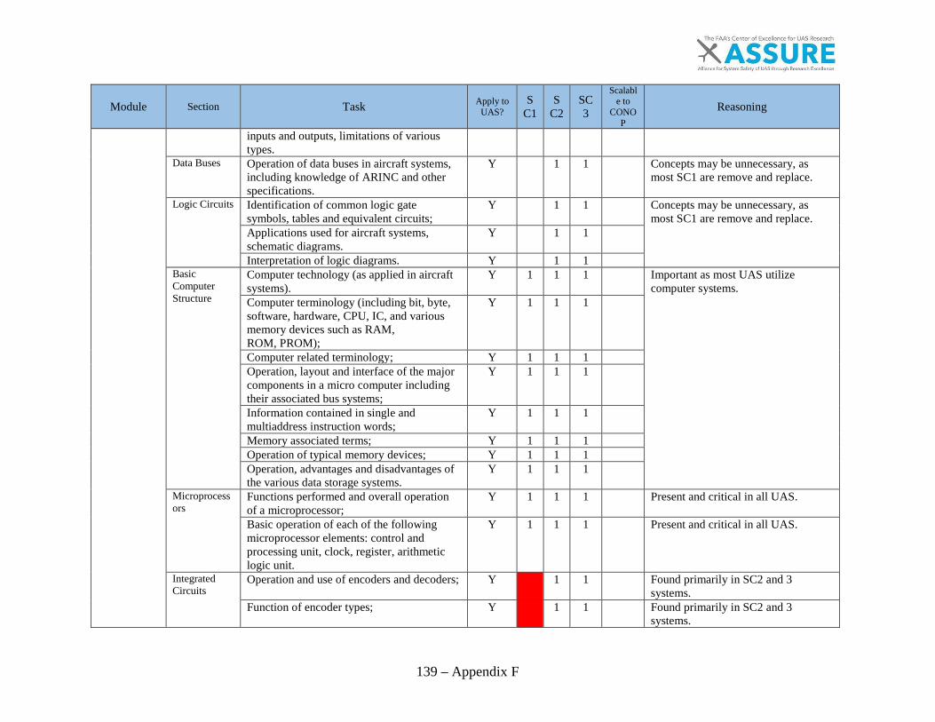
139 – Appendix F
Module Section Task Apply to UAS?
SC1
SC2
SC3
Scalable to
CONOP
Reasoning
inputs and outputs, limitations of various types.
Data Buses Operation of data buses in aircraft systems, including knowledge of ARINC and other specifications.
Y
1 1
Concepts may be unnecessary, as most SC1 are remove and replace.
Logic Circuits Identification of common logic gate symbols, tables and equivalent circuits;
Y
1 1
Concepts may be unnecessary, as most SC1 are remove and replace. Applications used for aircraft systems,
schematic diagrams. Y
1 1
Interpretation of logic diagrams. Y
1 1
Basic Computer Structure
Computer technology (as applied in aircraft systems).
Y 1 1 1
Important as most UAS utilize computer systems. Computer terminology (including bit, byte,
software, hardware, CPU, IC, and various memory devices such as RAM, ROM, PROM);
Y 1 1 1
Computer related terminology; Y 1 1 1
Operation, layout and interface of the major components in a micro computer including their associated bus systems;
Y 1 1 1
Information contained in single and multiaddress instruction words;
Y 1 1 1
Memory associated terms; Y 1 1 1
Operation of typical memory devices; Y 1 1 1
Operation, advantages and disadvantages of the various data storage systems.
Y 1 1 1
Microprocessors
Functions performed and overall operation of a microprocessor;
Y 1 1 1
Present and critical in all UAS.
Basic operation of each of the following microprocessor elements: control and processing unit, clock, register, arithmetic logic unit.
Y 1 1 1
Present and critical in all UAS.
Integrated Circuits
Operation and use of encoders and decoders; Y
1 1
Found primarily in SC2 and 3 systems.
Function of encoder types; Y
1 1
Found primarily in SC2 and 3 systems.

140 – Appendix F
Module Section Task Apply to UAS?
SC1
SC2
SC3
Scalable to
CONOP
Reasoning
Uses of medium, large and very large scale integration.
Y 1 1
Found primarily in SC2 and 3 systems.
Multiplexing Operation, application and identification in logic diagrams of multiplexers and demultiplexers.
Y 1 1 1
Fibre Optics Advantages and disadvantages of fibre optic data transmission over electrical wire propagation;
Y 1 1 Found primarily in SC2 and 3 systems.
Fibre optic data bus; Y 1 1 Fibre optic related terms; Y 1 1 Terminations; Y 1 1 Couplers, control terminals, remote terminals;
Y 1 1
Application of fibre optics in aircraft systems.
Y 1 1
Electronic Displays
Principles of operation of common types of displays used in modern aircraft, including
Y 1 1 1 Displays are found in most UAS CS.
Cathode Ray Tubes, Light Emitting Diodes and Liquid Crystal Display.
Y 1 1 1 Displays are found in most UAS CS.
Electrostatic Sensitive Devices
Special handling of components sensitive to electrostatic discharges;
Y 1 1 1 All UAS electronics have risk for damage to ESDs.
Awareness of risks and possible damage, component and personnel anti-static protection devices.
Y 1 1 1 All UAS electronics have risk for damage to ESDs.
Software Management Control
Awareness of restrictions, airworthiness requirements and possible catastrophic effects of unapproved changes to software programmes.
Y 1 1 1 The application of this line would only apply if the same requirements exist for UAS software.
Electromagnetic Environment
Influence of the following phenomena on maintenance practices for electronic system:
G
EMC-Electromagnetic Compatibility Y 1 1 1 All UAS are subject to EMI and producing interference themselves.
EMI-Electromagnetic Interference Y 1 1 1 All UAS are subject to EMI and producing interference themselves.
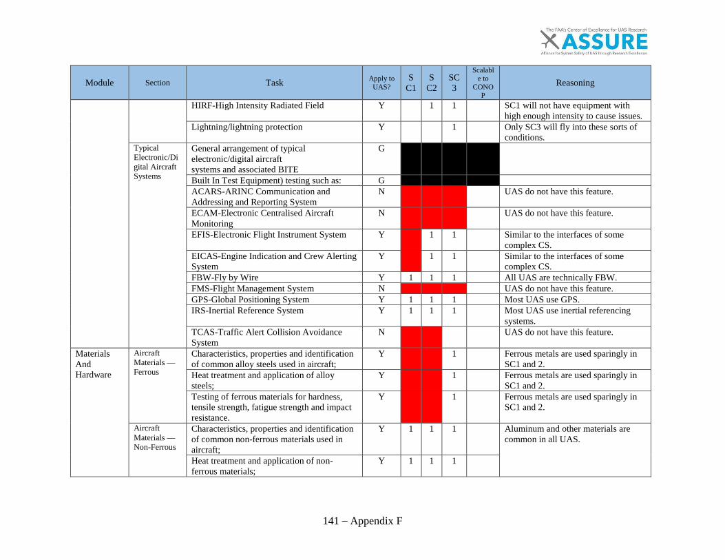
141 – Appendix F
Module Section Task Apply to UAS?
SC1
SC2
SC3
Scalable to
CONOP
Reasoning
HIRF-High Intensity Radiated Field Y
1 1
SC1 will not have equipment with high enough intensity to cause issues.
Lightning/lightning protection Y
1
Only SC3 will fly into these sorts of conditions.
Typical Electronic/Digital Aircraft Systems
General arrangement of typical electronic/digital aircraft systems and associated BITE
G
Built In Test Equipment) testing such as: G
ACARS-ARINC Communication and Addressing and Reporting System
N
UAS do not have this feature.
ECAM-Electronic Centralised Aircraft Monitoring
N
UAS do not have this feature.
EFIS-Electronic Flight Instrument System Y
1 1
Similar to the interfaces of some complex CS.
EICAS-Engine Indication and Crew Alerting System
Y
1 1
Similar to the interfaces of some complex CS.
FBW-Fly by Wire Y 1 1 1
All UAS are technically FBW. FMS-Flight Management System N
UAS do not have this feature.
GPS-Global Positioning System Y 1 1 1
Most UAS use GPS. IRS-Inertial Reference System Y 1 1 1
Most UAS use inertial referencing systems.
TCAS-Traffic Alert Collision Avoidance System
N
UAS do not have this feature.
Materials And Hardware
Aircraft Materials — Ferrous
Characteristics, properties and identification of common alloy steels used in aircraft;
Y
1
Ferrous metals are used sparingly in SC1 and 2.
Heat treatment and application of alloy steels;
Y
1
Ferrous metals are used sparingly in SC1 and 2.
Testing of ferrous materials for hardness, tensile strength, fatigue strength and impact resistance.
Y
1
Ferrous metals are used sparingly in SC1 and 2.
Aircraft Materials — Non-Ferrous
Characteristics, properties and identification of common non-ferrous materials used in aircraft;
Y 1 1 1
Aluminum and other materials are common in all UAS.
Heat treatment and application of non-ferrous materials;
Y 1 1 1

142 – Appendix F
Module Section Task Apply to UAS?
SC1
SC2
SC3
Scalable to
CONOP
Reasoning
Testing of non-ferrous material for hardness, tensile strength, fatigue strength and impact resistance.
Y 1 1 1
Aircraft Materials — Composite and Non-Metallic Aircraft Composite and non-metallic other than wood and fabric
Characteristics, properties and identification of common composite and non-metallic materials, other than wood
Y 1 1 1
Nonmetallic materials are used in all classes of UAS.
Sealant and bonding agents. Y 1 1 1
Nonmetallic materials are used in all classes of UAS. The detection of defects/deterioration in
composite and non-metallic material. Y 1 1 1
Repair of composite and non-metallic material.
Y 1 1 1
Y 1 1 1
Aircraft Materials — Composite and Non-Metallic Wooden structures
Construction methods of wooden airframe structures;
N
Wooden structures are not often used in UAS that are for non-hobby use.
Characteristics, properties and types of wood and glue used in aeroplanes;
N
Wooden structures are not often used in UAS that are for non-hobby use. Preservation and maintenance of wooden
structure; N
Types of defects in wood material and wooden structures;
N
The detection of defects in wooden structure; N
Repair of wooden structure. N
Aircraft Materials — Composite and Non-Metallic Fabric covering
Characteristics, properties and types of fabrics used in aeroplanes;
N
Wooden structures are not often used in UAS that are for non-hobby use. Inspections methods for fabric; N
Types of defects in fabric; N
Repair of fabric covering. N
Corrosion Chemical fundamentals; Y 1 1 1
The electronics and metal hardware and structures on UAS are also susceptible to corrosion.
Formation by, galvanic action process, microbiological, stress;
Y 1 1 1
Types of corrosion and their identification; Y 1 1 1
Causes of corrosion; Y 1 1 1
Material types, susceptibility to corrosion. Y 1 1 1

143 – Appendix F
Module Section Task Apply to UAS?
SC1
SC2
SC3
Scalable to
CONOP
Reasoning
Fasteners – Screws
Screw nomenclature; Y 1 1 1
Knowing the type of screw prevents use of the wrong screw.
Thread forms, dimensions and tolerances for standard threads used in aircraft;
Y
1 1
SC1 is too small for this to apply.
Measuring screw threads; Y
1 1
SC1 is too small for this to apply. Fasteners -Bolts, studs and screws
Bolt types: specification, identification and marking of aircraft bolts, international standards;
Y 1 1 1
Present in all classes of UAS.
Nuts: self locking, anchor, standard types; Y 1 1 1
Machine screws: aircraft specifications; Y 1 1 1
Studs: types and uses, insertion and removal; Y 1 1 1
Self tapping screws, dowels. Y 1 1 1
Fasteners – Locking devices
Tab and spring washers, locking plates, split pins, pal-nuts, wire locking, quick release fasteners, keys, circlips, cotter pins.
Y
1 1
Uncommon on SC1.
Fasteners – Aircraft Rivets
Types of solid and blind rivets: specifications and identification, heat treatment.
Y
1
Not observed on anything lower than SC3.
Pipes and Unions
Identification of, and types of rigid and flexible pipes and their connectors used in aircraft;
Y
1 1
Useful for larger engines and launchers.
Standard unions for aircraft hydraulic, fuel, oil, pneumatic and air system pipes.
Y
1 1
Useful for larger engines and launchers.
Springs Types of springs, materials, characteristics and applications.
Y 1 1 1
Can be found in all classes of UAS.
Bearings Purpose of bearings, loads, material, construction;
Y 1 1 1
Can be found in all classes of UAS.
Types of bearings and their application. Y 1 1 1
Can be found in all classes of UAS. Transmissions Gear types and their application; Y
1
Only observed on SC3. Gear ratios, reduction and multiplication
gear systems, driven and driving gears, idler gears, mesh patterns;
Y
1
Belts and pulleys, chains and sprockets. Y
1
Control Cables
Types of cables; Y
1 1
Standard manned aircraft control cabling is different from SC1.
End fittings, turnbuckles and compensation devices;
Y
1 1

144 – Appendix F
Module Section Task Apply to UAS?
SC1
SC2
SC3
Scalable to
CONOP
Reasoning
Pulleys and cable system components; Y
1 1
Bowden cables; Y
1 1
Aircraft flexible control systems. Y
1 1
Electrical Cables and Connectors
Cable types, construction and characteristics; Y 1 1 1
A lot of the same cabling and connectors found in manned aviation can be found in UAS.
High tension and co-axial cables; Y 1 1 1
Crimping; Y 1 1 1
Connector types, pins, plugs, sockets, insulators, current and voltage rating, coupling, identification codes.
Y 1 1 1
Maintenance Practices
Safety Precautions-Aircraft and Workshop
Aspects of safe working practices including precautions to take when working with electricity, gases especially oxygen, oils and chemicals.
Y 1 1 1
Safety practices can be applied to UAS.
Also, instruction in the remedial action to be taken in the event of a fire or another accident with one or more of these hazards including knowledge on extinguishing agents.
Y 1 1 1
Workshop Practices
Care of tools, control of tools, use of workshop materials;
Y 1 1 1
Workshop standards can prevent a hazardous shop. Dimensions, allowances and tolerances,
standards of workmanship; Y 1 1 1
Calibration of tools and equipment, calibration standards.
Y 1 1 1
Tools Common hand tool types; Y 1 1 1
Knowing what tools are available and how to use them helps get work finished correctly.
Common power tool types; Y 1 1 1
Operation and use of precision measuring tools;
Y 1 1 1
Lubrication equipment and methods. Y 1 1 1
Operation, function and use of electrical general test equipment;
Y 1 1 1
Avionic General Test Equipment
Operation, function and use of avionic general test equipment.
Y 1 1 1
Knowing what tools are available and how to use them helps get work finished correctly.
Engineering Drawings,
Drawing types and diagrams, their symbols, dimensions, tolerances and projections;
Y
1 1
SC1 does not have these.
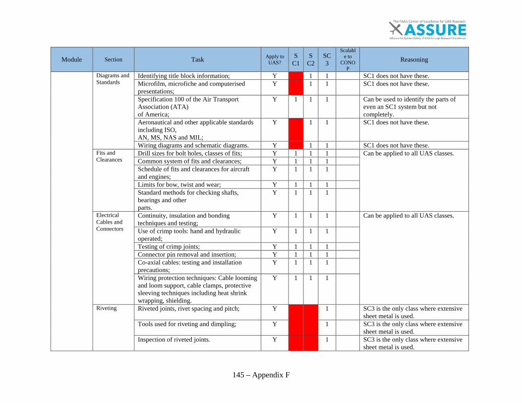
145 – Appendix F
Module Section Task Apply to UAS?
SC1
SC2
SC3
Scalable to
CONOP
Reasoning
Diagrams and Standards
Identifying title block information; Y
1 1
SC1 does not have these. Microfilm, microfiche and computerised presentations;
Y
1 1
SC1 does not have these.
Specification 100 of the Air Transport Association (ATA) of America;
Y 1 1 1
Can be used to identify the parts of even an SC1 system but not completely.
Aeronautical and other applicable standards including ISO, AN, MS, NAS and MIL;
Y
1 1
SC1 does not have these.
Wiring diagrams and schematic diagrams. Y
1 1
SC1 does not have these. Fits and Clearances
Drill sizes for bolt holes, classes of fits; Y 1 1 1
Can be applied to all UAS classes. Common system of fits and clearances; Y 1 1 1
Schedule of fits and clearances for aircraft and engines;
Y 1 1 1
Limits for bow, twist and wear; Y 1 1 1
Standard methods for checking shafts, bearings and other parts.
Y 1 1 1
Electrical Cables and Connectors
Continuity, insulation and bonding techniques and testing;
Y 1 1 1
Can be applied to all UAS classes.
Use of crimp tools: hand and hydraulic operated;
Y 1 1 1
Testing of crimp joints; Y 1 1 1
Connector pin removal and insertion; Y 1 1 1
Co-axial cables: testing and installation precautions;
Y 1 1 1
Wiring protection techniques: Cable looming and loom support, cable clamps, protective sleeving techniques including heat shrink wrapping, shielding.
Y 1 1 1
Riveting Riveted joints, rivet spacing and pitch; Y
1
SC3 is the only class where extensive sheet metal is used.
Tools used for riveting and dimpling; Y
1
SC3 is the only class where extensive sheet metal is used.
Inspection of riveted joints. Y
1
SC3 is the only class where extensive sheet metal is used.

146 – Appendix F
Module Section Task Apply to UAS?
SC1
SC2
SC3
Scalable to
CONOP
Reasoning
Pipes and Hoses
Bending and belling/flaring aircraft pipes; Y
1
Minimal piping and hoses are used in SC1 and 2 other than for fuel which is covered elsewhere.
Inspection and testing of aircraft pipes and hoses;
Y
1
Installation and clamping of pipes. Y
1
Springs Inspection and testing of springs. Y 1 1 1
Springs are used in various sizes on all classes of UAS.
Bearings Testing, cleaning and inspection of bearings; Y 1 1 1
Applies to bearings of all sizes and most types.
Lubrication requirements of bearings; Y 1 1 1
Applies to bearings of all sizes and most types.
Defects in bearings and their causes. Y 1 1 1
Applies to bearings of all sizes and most types.
Transmissions Inspection of gears, backlash; Y
1
Only used in SC3. Inspection of belts and pulleys, chains and sprockets;
Y
1 1
SC1 does not utilize these components.
Inspection of screw jacks, lever devices, push-pull rod systems.
Y 1 1 1
Similar components are found scaled down in to SC1 and 2.
Control Cables
Swaging of end fittings; Y
1
SC1 and 2 primarily use solid linkages instead of cables. Inspection and testing of control cables; Y
1
Bowden cables; aircraft flexible control systems.
Y
1
Material handling – Sheet Metal
Marking out and calculation of bend allowance;
Y
1
SC3 is the only class where extensive sheet metal is used. Sheet metal working, including bending and
forming; Y
1
Inspection of sheet metal work. Y
1
Material handling – Composites and Non-metallic
Bonding practices; Y 1 1 1
Composites and non-metallic materials are used a lot of most UAS. Environmental conditions Y 1 1 1
Inspection methods Y 1 1 1
Welding, Brazing, Soldering and Bonding
Soldering methods; inspection of soldered joints.
Y
1
SC3 is the only class where extensive metals are used.
Welding and brazing methods; Y
1
SC3 is the only class where extensive metals are used.
Inspection of welded and brazed joints; Y
1
SC3 is the only class where extensive metals are used.

147 – Appendix F
Module Section Task Apply to UAS?
SC1
SC2
SC3
Scalable to
CONOP
Reasoning
Bonding methods and inspection of bonded joints.
Y
1
SC3 is the only class where extensive metals are used.
Aircraft Weight and Balance
Centre of Gravity/Balance limits calculation: use of relevant documents;
Y
1 1
Weighing and balancing methods for manned aircraft are different from how SC1 is weighed and balanced. Preparation of aircraft for weighing; Y
1 1
Aircraft weighing; Y
1 1
Aircraft Handling and Storage
Aircraft taxiing/towing and associated safety precautions;
Y
1 1
SC1 does not require taxi or tow, hand carry.
Aircraft jacking, chocking, securing and associated safety precautions;
Y
1 1
Not required on aircraft that are smaller than SC2. Jacking procedures may be unique on SC2.
Aircraft storage methods; Y
1 1
SC1 aircraft are stored similar to model aircraft while SC2 and 3 are stored similarly to manned.
Refuelling/defuelling procedures; Y 1 1 1
Many fueling, defueling considerations are the same across the board.
De-icing/anti-icing procedures; Y
1
Only present on SC3. Electrical, hydraulic and pneumatic ground supplies.
Y
1
Only present on SC3.
Effects of environmental conditions on aircraft handling and operation.
Y 1 1 1
Effects effect all classes of UAS.
Disassembly, Inspection, Repair and Assembly Techniques
Types of defects and visual inspection techniques.
Y 1 1 1
Methods may work on UAS.
Corrosion removal, assessment and reprotection.
Y 1 1 1
General repair methods, Structural Repair Manual;
Y 1 1 1
Ageing, fatigue and corrosion control programmes;
Y 1 1 1
Non destructive inspection techniques including, penetrant, radiographic, eddy current, ultrasonic and boroscope methods.
Y
1 1
Methods may work on UAS but SC1 uses materials to which they may not apply.
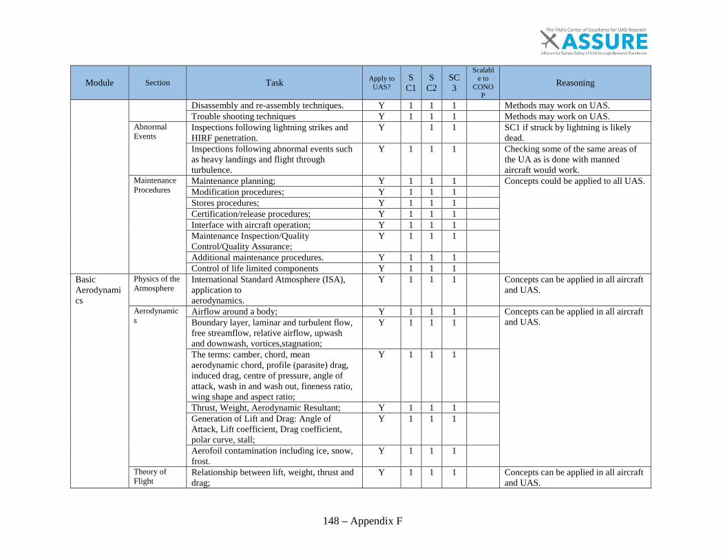
148 – Appendix F
Module Section Task Apply to UAS?
SC1
SC2
SC3
Scalable to
CONOP
Reasoning
Disassembly and re-assembly techniques. Y 1 1 1
Methods may work on UAS. Trouble shooting techniques Y 1 1 1
Methods may work on UAS.
Abnormal Events
Inspections following lightning strikes and HIRF penetration.
Y
1 1
SC1 if struck by lightning is likely dead.
Inspections following abnormal events such as heavy landings and flight through turbulence.
Y 1 1 1
Checking some of the same areas of the UA as is done with manned aircraft would work.
Maintenance Procedures
Maintenance planning; Y 1 1 1
Concepts could be applied to all UAS. Modification procedures; Y 1 1 1
Stores procedures; Y 1 1 1
Certification/release procedures; Y 1 1 1
Interface with aircraft operation; Y 1 1 1
Maintenance Inspection/Quality Control/Quality Assurance;
Y 1 1 1
Additional maintenance procedures. Y 1 1 1
Control of life limited components Y 1 1 1
Basic Aerodynamics
Physics of the Atmosphere
International Standard Atmosphere (ISA), application to aerodynamics.
Y 1 1 1
Concepts can be applied in all aircraft and UAS.
Aerodynamics
Airflow around a body; Y 1 1 1
Concepts can be applied in all aircraft and UAS. Boundary layer, laminar and turbulent flow,
free streamflow, relative airflow, upwash and downwash, vortices,stagnation;
Y 1 1 1
The terms: camber, chord, mean aerodynamic chord, profile (parasite) drag, induced drag, centre of pressure, angle of attack, wash in and wash out, fineness ratio, wing shape and aspect ratio;
Y 1 1 1
Thrust, Weight, Aerodynamic Resultant; Y 1 1 1
Generation of Lift and Drag: Angle of Attack, Lift coefficient, Drag coefficient, polar curve, stall;
Y 1 1 1
Aerofoil contamination including ice, snow, frost.
Y 1 1 1
Theory of Flight
Relationship between lift, weight, thrust and drag;
Y 1 1 1
Concepts can be applied in all aircraft and UAS.

149 – Appendix F
Module Section Task Apply to UAS?
SC1
SC2
SC3
Scalable to
CONOP
Reasoning
Glide ratio; Y 1 1 1
Steady state flights, performance; Y 1 1 1
Theory of the turn; Y 1 1 1
Influence of load factor: stall, flight envelope and structural limitations;
Y 1 1 1
Lift augmentation. Y 1 1 1
Flight Stability and Dynamics
Longitudinal, lateral and directional stability (active and passive).
Y 1 1 1
Concepts can be applied in all aircraft and UAS.
Human Factors
General The need to take human factors into account; Y 1 1 1
Human factors affect all types of work including operation of UAS.
Incidents attributable to human factors/human error;
Y 1 1 1
‘Murphy's’ law. Y 1 1 1
Human Performance and Limitations
Vision Y 1 1 1
Human factors affect all types of work including operation of UAS.
Information Processing Y 1 1 1
Attention and perception; Y 1 1 1
Memory associated terms; Y 1 1 1
Claustrophobia and physical access. Y 1 1 1
Hearing Y 1 1 1
Social Psychology
Responsibility: individual and group; Y 1 1 1
Human factors affect all types of work including operation of UAS.
Motivation and de-motivation; Y 1 1 1
Peer pressure; Y 1 1 1
‘Culture’ issues; Y 1 1 1
Team working; Y 1 1 1
Management, supervision and leadership. Y 1 1 1
Factors Affecting Performance
Fitness/health; Y 1 1 1
Human factors affect all types of work including operation of UAS. Stress: domestic and work related; Y 1 1 1
Time pressure and deadlines; Y 1 1 1
Workload: overload and underload; Y 1 1 1
Sleep and fatigue, shiftwork; Y 1 1 1
Alcohol, medication, drug abuse. Y 1 1 1
Physical Environment
Noise and fumes; Y 1 1 1
Human factors affect all types of work including operation of UAS.
Illumination; Y 1 1 1
Climate and temperature; Y 1 1 1
Motion and vibration; Y 1 1 1

150 – Appendix F
Module Section Task Apply to UAS?
SC1
SC2
SC3
Scalable to
CONOP
Reasoning
Working environment. Y 1 1 1
Tasks Physical work; Y 1 1 1
Human factors affect all types of work including operation of UAS.
Repetitive tasks; Y 1 1 1
Visual inspection; Y 1 1 1
Complex systems. Y 1 1 1
Communication
Within and between teams; Y 1 1 1
Human factors affect all types of work including operation of UAS.
Work logging and recording; Y 1 1 1
Keeping up to date, currency; Y 1 1 1
Dissemination of information. Y 1 1 1
Human Error Error models and theories; Y 1 1 1
Human factors affect all types of work including operation of UAS.
Types of error in maintenance tasks; Y 1 1 1
Implications of errors (i.e accidents) Y 1 1 1
Avoiding and managing errors. Y 1 1 1
Hazards in the Workplace
Recognising and avoiding hazards; Y 1 1 1
Human factors affect all types of work including operation of UAS. Dealing with emergencies. Y 1 1 1
Aviation Legislation
Regulatory Framework
Role of International Civil Aviation Organisation;
Y 1 1 1
ICAO standards could be used for UAS.
Role of EASA; N
Not applicable to the USA. Role of the Member States; N
Not applicable to the USA.
Relationship between Part-145, Part-66, Part-147 and Part- M;
N
Not applicable unless regulations are rewritten for UAS.
Relationship with other Aviation Authorities. N
Not applicable to the USA. Part-66 — Certifying Staff — Maintenance
Detailed understanding of Part-66. N
Not applicable to the USA.
Part-145 — Approved Maintenance Organisations
Detailed understanding of Part-145. Y 1 1 1
Applies if 145 is rewritten to include UAS Maintenance organizations.
JAR-OPS — Commercial Air Transportation
Air Operators Certificates; N
Not applicable to the USA. Operators Responsibilities; N
Documents to be Carried; N
Aircraft Placarding (Markings); N
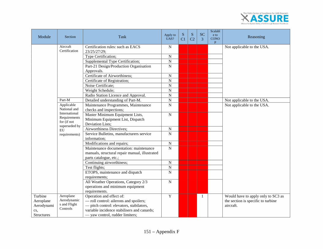
151 – Appendix F
Module Section Task Apply to UAS?
SC1
SC2
SC3
Scalable to
CONOP
Reasoning
Aircraft Certification
Certification rules: such as EACS 23/25/27/29;
N
Not applicable to the USA.
Type Certification; N
Supplemental Type Certification; N
Part-21 Design/Production Organisation Approvals.
N
Certificate of Airworthiness; N
Certificate of Registration; N
Noise Certificate; N
Weight Schedule; N
Radio Station Licence and Approval. N
Part-M Detailed understanding of Part-M. N
Not applicable to the USA. Applicable National and International Requirements for (if not superseded by EU requirements)
Maintenance Programmes, Maintenance checks and inspections;
N
Not applicable to the USA.
Master Minimum Equipment Lists, Minimum Equipment List, Dispatch Deviation Lists;
N
Airworthiness Directives; N
Service Bulletins, manufacturers service information;
N
Modifications and repairs; N
Maintenance documentation: maintenance manuals, structural repair manual, illustrated parts catalogue, etc.;
N
Continuing airworthiness; N
Test flights; N
ETOPS, maintenance and dispatch requirements;
N
All Weather Operations, Category 2/3 operations and minimum equipment requirements.
N
Turbine Aeroplane Aerodynamics, Structures
Aeroplane Aerodynamics and Flight Controls
Operation and effect of: — roll control: ailerons and spoilers; — pitch control: elevators, stabilators, variable incidence stabilisers and canards; — yaw control, rudder limiters;
Y
1
Would have to apply only to SC3 as the section is specific to turbine aircraft.
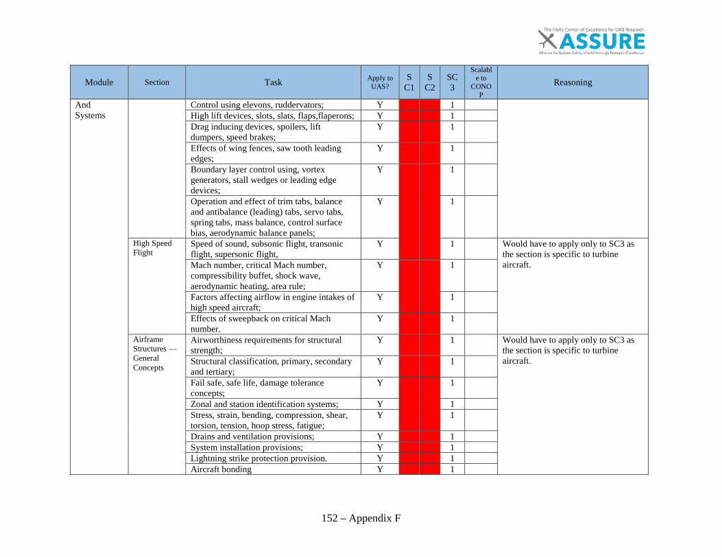
152 – Appendix F
Module Section Task Apply to UAS?
SC1
SC2
SC3
Scalable to
CONOP
Reasoning
And Systems
Control using elevons, ruddervators; Y
1
High lift devices, slots, slats, flaps,flaperons; Y
1
Drag inducing devices, spoilers, lift dumpers, speed brakes;
Y
1
Effects of wing fences, saw tooth leading edges;
Y
1
Boundary layer control using, vortex generators, stall wedges or leading edge devices;
Y
1
Operation and effect of trim tabs, balance and antibalance (leading) tabs, servo tabs, spring tabs, mass balance, control surface bias, aerodynamic balance panels;
Y
1
High Speed Flight
Speed of sound, subsonic flight, transonic flight, supersonic flight,
Y
1
Would have to apply only to SC3 as the section is specific to turbine aircraft.
Mach number, critical Mach number, compressibility buffet, shock wave, aerodynamic heating, area rule;
Y
1
Factors affecting airflow in engine intakes of high speed aircraft;
Y
1
Effects of sweepback on critical Mach number.
Y
1
Airframe Structures — General Concepts
Airworthiness requirements for structural strength;
Y
1
Would have to apply only to SC3 as the section is specific to turbine aircraft.
Structural classification, primary, secondary and tertiary;
Y
1
Fail safe, safe life, damage tolerance concepts;
Y
1
Zonal and station identification systems; Y
1
Stress, strain, bending, compression, shear, torsion, tension, hoop stress, fatigue;
Y
1
Drains and ventilation provisions; Y
1
System installation provisions; Y
1
Lightning strike protection provision. Y
1
Aircraft bonding Y
1
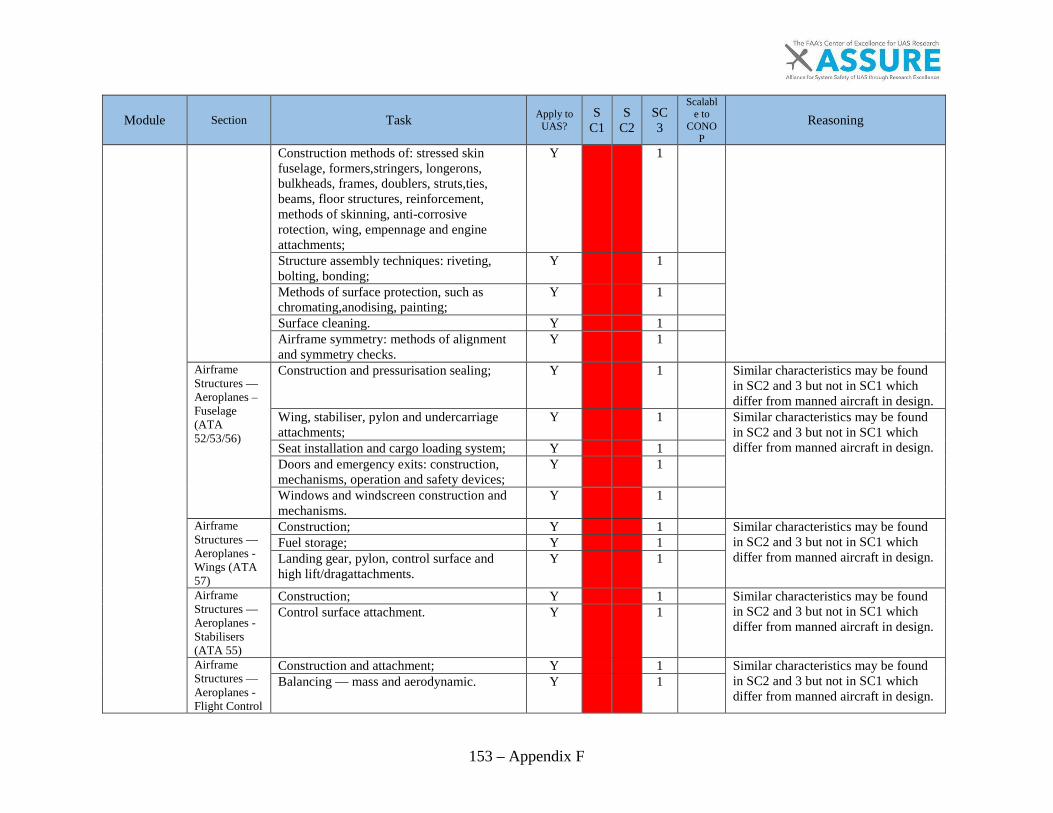
153 – Appendix F
Module Section Task Apply to UAS?
SC1
SC2
SC3
Scalable to
CONOP
Reasoning
Construction methods of: stressed skin fuselage, formers,stringers, longerons, bulkheads, frames, doublers, struts,ties, beams, floor structures, reinforcement, methods of skinning, anti-corrosive rotection, wing, empennage and engine attachments;
Y
1
Structure assembly techniques: riveting, bolting, bonding;
Y
1
Methods of surface protection, such as chromating,anodising, painting;
Y
1
Surface cleaning. Y
1
Airframe symmetry: methods of alignment and symmetry checks.
Y
1
Airframe Structures — Aeroplanes – Fuselage (ATA 52/53/56)
Construction and pressurisation sealing; Y
1
Similar characteristics may be found in SC2 and 3 but not in SC1 which differ from manned aircraft in design.
Wing, stabiliser, pylon and undercarriage attachments;
Y
1
Similar characteristics may be found in SC2 and 3 but not in SC1 which differ from manned aircraft in design. Seat installation and cargo loading system; Y
1
Doors and emergency exits: construction, mechanisms, operation and safety devices;
Y
1
Windows and windscreen construction and mechanisms.
Y
1
Airframe Structures — Aeroplanes -Wings (ATA 57)
Construction; Y
1
Similar characteristics may be found in SC2 and 3 but not in SC1 which differ from manned aircraft in design.
Fuel storage; Y
1
Landing gear, pylon, control surface and high lift/dragattachments.
Y
1
Airframe Structures — Aeroplanes -Stabilisers (ATA 55)
Construction; Y
1
Similar characteristics may be found in SC2 and 3 but not in SC1 which differ from manned aircraft in design.
Control surface attachment. Y
1
Airframe Structures — Aeroplanes -Flight Control
Construction and attachment; Y
1
Similar characteristics may be found in SC2 and 3 but not in SC1 which differ from manned aircraft in design.
Balancing — mass and aerodynamic. Y
1

154 – Appendix F
Module Section Task Apply to UAS?
SC1
SC2
SC3
Scalable to
CONOP
Reasoning
Surfaces (ATA 55/57) Airframe Structures — Aeroplanes- Nacelles/Pylons (ATA 54)
Construction; Y
1
Similar characteristics may be found in SC2 and 3 but not in SC1 which differ from manned aircraft in design.
Firewalls; Y
1
Engine mounts. Y
1
Air Conditioning and Cabin Pressurisation (ATA 21)- Air Supply
Sources of air supply including engine bleed, APU and ground cart;
Y
1 Not needed without passengers.
Air Conditioning and Cabin Pressurisation (ATA 21)-Air Conditioning
Air conditioning systems; Y
1 UAS do not need air conditioning without passengers. Air cycle and vapour cycle machines; Y
1
Distribution systems; Y
1 Flow, temperature and humidity control system.
Y
1
Air Conditioning and Cabin Pressurisation (ATA 21)-Pressurization
Pressurisation systems; N
UAS currently in existence do not carry passengers at high altitude. Control and indication including control and
safety valves; N
Cabin pressure controllers. N
(ATA 21)-Safety and warning devices
Protection and warning devices. Y
1
Would have to apply only to SC3 as the section is specific to turbine aircraft.
Instruments/Avionic Systems-Instrument Systems (ATA 31)
Pitot static: altimeter, air speed indicator, vertical speed indicator
Y
1
Would have to apply only to SC3 as the section is specific to turbine aircraft.
Gyroscopic: artificial horizon, attitude director, direction indicator, horizontal situation indicator, turn and slip indicator, turn coordinator
Y
1
Compasses: direct reading, remote reading; Y
1
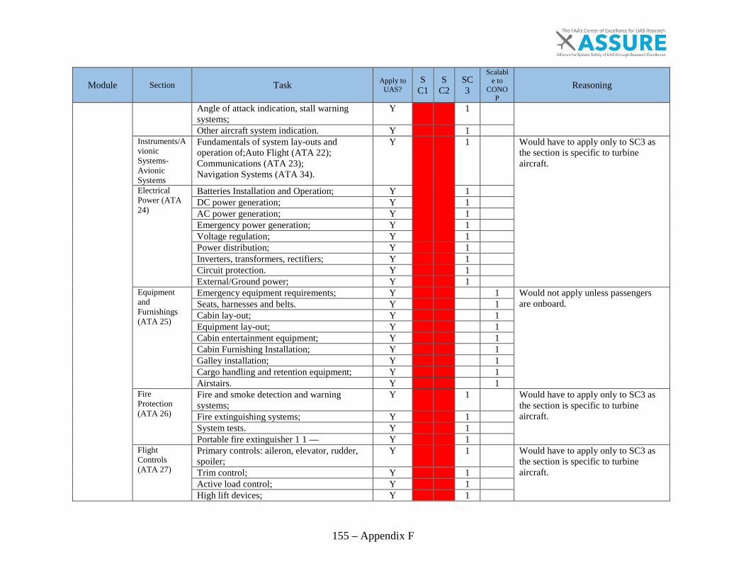
155 – Appendix F
Module Section Task Apply to UAS?
SC1
SC2
SC3
Scalable to
CONOP
Reasoning
Angle of attack indication, stall warning systems;
Y
1
Other aircraft system indication. Y
1
Instruments/Avionic Systems-Avionic Systems
Fundamentals of system lay-outs and operation of;Auto Flight (ATA 22); Communications (ATA 23); Navigation Systems (ATA 34).
Y
1
Would have to apply only to SC3 as the section is specific to turbine aircraft.
Electrical Power (ATA 24)
Batteries Installation and Operation; Y
1
DC power generation; Y
1
AC power generation; Y
1
Emergency power generation; Y
1
Voltage regulation; Y
1
Power distribution; Y
1
Inverters, transformers, rectifiers; Y
1
Circuit protection. Y
1
External/Ground power; Y
1
Equipment and Furnishings (ATA 25)
Emergency equipment requirements; Y
1 Would not apply unless passengers are onboard.
Seats, harnesses and belts. Y
1 Cabin lay-out; Y
1
Equipment lay-out; Y
1 Cabin entertainment equipment; Y
1
Cabin Furnishing Installation; Y
1 Galley installation; Y
1
Cargo handling and retention equipment; Y
1 Airstairs. Y
1
Fire Protection (ATA 26)
Fire and smoke detection and warning systems;
Y
1
Would have to apply only to SC3 as the section is specific to turbine aircraft.
Fire extinguishing systems; Y
1
System tests. Y
1
Portable fire extinguisher 1 1 — Y
1
Flight Controls (ATA 27)
Primary controls: aileron, elevator, rudder, spoiler;
Y
1
Would have to apply only to SC3 as the section is specific to turbine aircraft. Trim control; Y
1
Active load control; Y
1
High lift devices; Y
1
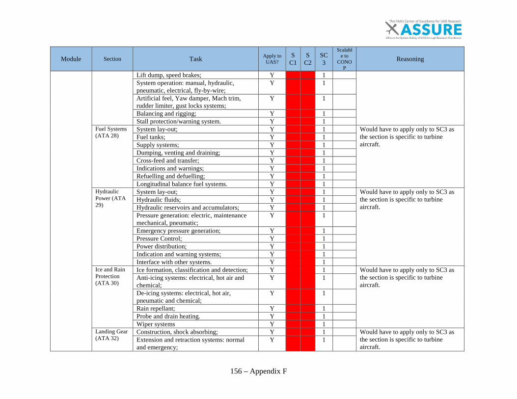
156 – Appendix F
Module Section Task Apply to UAS?
SC1
SC2
SC3
Scalable to
CONOP
Reasoning
Lift dump, speed brakes; Y
1
System operation: manual, hydraulic, pneumatic, electrical, fly-by-wire;
Y
1
Artificial feel, Yaw damper, Mach trim, rudder limiter, gust locks systems;
Y
1
Balancing and rigging; Y
1
Stall protection/warning system. Y
1
Fuel Systems (ATA 28)
System lay-out; Y
1
Would have to apply only to SC3 as the section is specific to turbine aircraft.
Fuel tanks; Y
1
Supply systems; Y
1
Dumping, venting and draining; Y
1
Cross-feed and transfer; Y
1
Indications and warnings; Y
1
Refuelling and defuelling; Y
1
Longitudinal balance fuel systems. Y
1
Hydraulic Power (ATA 29)
System lay-out; Y
1
Would have to apply only to SC3 as the section is specific to turbine aircraft.
Hydraulic fluids; Y
1
Hydraulic reservoirs and accumulators; Y
1
Pressure generation: electric, maintenance mechanical, pneumatic;
Y
1
Emergency pressure generation; Y
1
Pressure Control; Y
1
Power distribution; Y
1
Indication and warning systems; Y
1
Interface with other systems. Y
1
Ice and Rain Protection (ATA 30)
Ice formation, classification and detection; Y
1
Would have to apply only to SC3 as the section is specific to turbine aircraft.
Anti-icing systems: electrical, hot air and chemical;
Y
1
De-icing systems: electrical, hot air, pneumatic and chemical;
Y
1
Rain repellant; Y
1
Probe and drain heating. Y
1
Wiper systems Y
1
Landing Gear (ATA 32)
Construction, shock absorbing; Y
1
Would have to apply only to SC3 as the section is specific to turbine aircraft.
Extension and retraction systems: normal and emergency;
Y
1
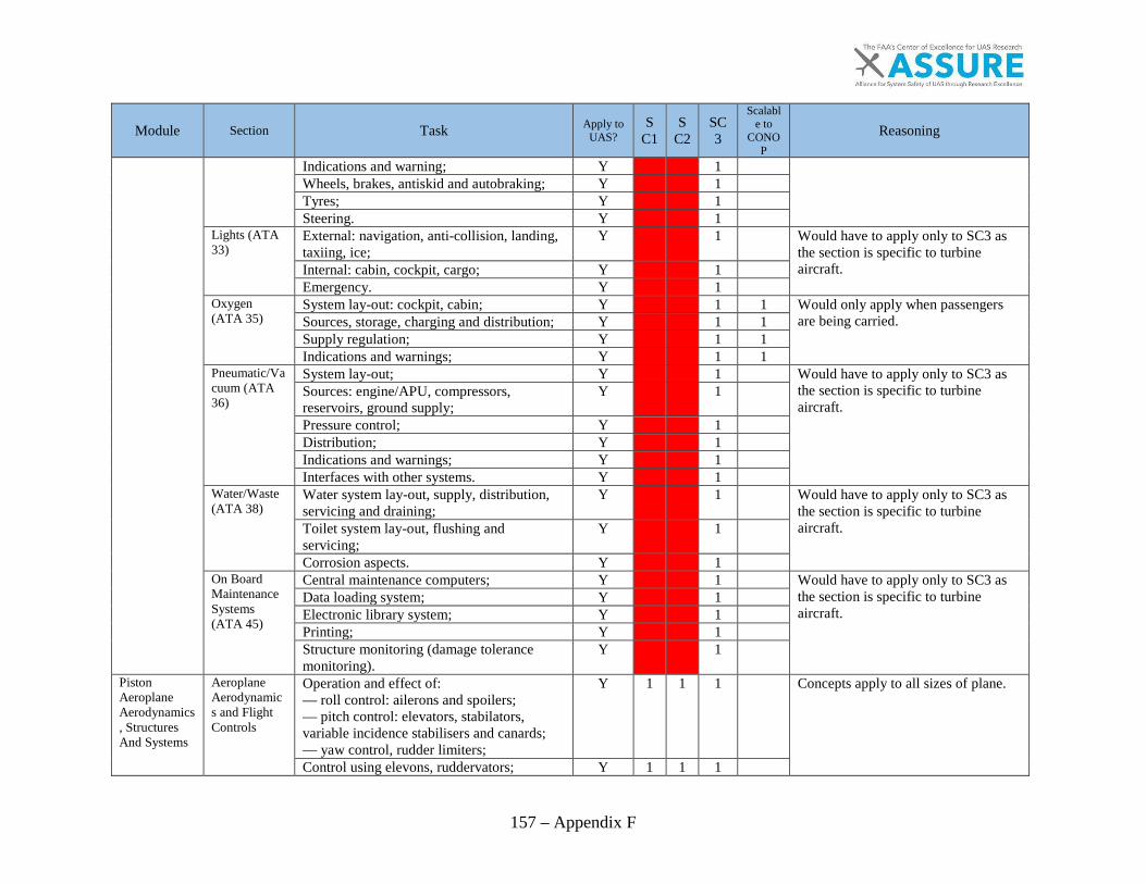
157 – Appendix F
Module Section Task Apply to UAS?
SC1
SC2
SC3
Scalable to
CONOP
Reasoning
Indications and warning; Y
1
Wheels, brakes, antiskid and autobraking; Y
1
Tyres; Y
1
Steering. Y
1
Lights (ATA 33)
External: navigation, anti-collision, landing, taxiing, ice;
Y
1
Would have to apply only to SC3 as the section is specific to turbine aircraft. Internal: cabin, cockpit, cargo; Y
1
Emergency. Y
1
Oxygen (ATA 35)
System lay-out: cockpit, cabin; Y
1 1 Would only apply when passengers are being carried. Sources, storage, charging and distribution; Y
1 1
Supply regulation; Y
1 1 Indications and warnings; Y
1 1
Pneumatic/Vacuum (ATA 36)
System lay-out; Y
1
Would have to apply only to SC3 as the section is specific to turbine aircraft.
Sources: engine/APU, compressors, reservoirs, ground supply;
Y
1
Pressure control; Y
1
Distribution; Y
1
Indications and warnings; Y
1
Interfaces with other systems. Y
1
Water/Waste (ATA 38)
Water system lay-out, supply, distribution, servicing and draining;
Y
1
Would have to apply only to SC3 as the section is specific to turbine aircraft.
Toilet system lay-out, flushing and servicing;
Y
1
Corrosion aspects. Y
1
On Board Maintenance Systems (ATA 45)
Central maintenance computers; Y
1
Would have to apply only to SC3 as the section is specific to turbine aircraft.
Data loading system; Y
1
Electronic library system; Y
1
Printing; Y
1
Structure monitoring (damage tolerance monitoring).
Y
1
Piston Aeroplane Aerodynamics, Structures And Systems
Aeroplane Aerodynamics and Flight Controls
Operation and effect of: — roll control: ailerons and spoilers; — pitch control: elevators, stabilators, variable incidence stabilisers and canards; — yaw control, rudder limiters;
Y 1 1 1
Concepts apply to all sizes of plane.
Control using elevons, ruddervators; Y 1 1 1

158 – Appendix F
Module Section Task Apply to UAS?
SC1
SC2
SC3
Scalable to
CONOP
Reasoning
High lift devices, slots, slats, flaps, flaperons;
Y 1 1 1
Drag inducing devices, spoilers, lift dumpers, speed brakes;
Y 1 1 1
Effects of wing fences, saw tooth leading edges;
Y 1 1 1
Boundary layer control using, vortex generators, stall wedges or leading edge devices;
Y 1 1 1
Operation and effect of trim tabs, balance and antibalance (leading) tabs, servo tabs, spring tabs, mass balance, control surface bias, aerodynamic balance panels;
Y 1 1 1
Airframe Structures — General Concepts
Airworthiness requirements for structural strength;
Y 1 1 1
May apply though SC1 may need to be greater (unskilled pilots).
Structural classification, primary, secondary and tertiary;
Y 1 1 1
All sizes of plane can have these levels of structure.
Fail safe, safe life, damage tolerance concepts;
Y 1 1 1
These concepts apply to parts of UAS as well.
Zonal and station identification systems; Y
1 1
??? Stress, strain, bending, compression, shear, torsion, tension, hoop stress, fatigue;
Y 1 1 1
These sorts of damage and wear can occur on all classes.
Drains and ventilation provisions; Y
1 1
Not relevant to SC1 designs. System installation provisions; Y
1 1
???
Lightning strike protection provision. Y
1
SC1 and 2 do not use lightning protection.
Construction methods of: stressed skin fuselage, formers, stringers, longerons, bulkheads, frames, doublers, struts,ties, beams, floor structures, reinforcement, methods of skinning, anti-corrosive protection, wing, empennage and engine attachments;
Y
1 1
Construction methods for SC1 differ from manned aviation greatly.
Structure assembly techniques: riveting, bolting, bonding;
Y
1 1
Not relevant to SC1 designs.

159 – Appendix F
Module Section Task Apply to UAS?
SC1
SC2
SC3
Scalable to
CONOP
Reasoning
Methods of surface protection, such as chromating,anodising, painting;
Y
1 1
SC1 rarely uses coatings.
Surface cleaning; Y 1 1 1
Clean aircraft are more reliable. Airframe symmetry: methods of alignment and symmetry checks.
Y
1 1
Methods will likely not apply to SC1 designs and construction.
Airframe Structures — Aeroplanes-Fuselage (ATA 52/53/56)
Construction and pressurisation sealing; Y
1 Only required if flying passengers. Wing, tail-plane pylon and undercarriage attachments;
Y
1 1
???
Seat installation; Y
1 Only required if flying passengers. Doors and emergency exits: construction and operation;
Y
1 Only required if flying passengers.
Window and windscreen attachment. Y
1 Only required if flying passengers. Airframe Structures — Aeroplanes-Wings (ATA 57)
Construction; Y
1 1
Wing construction, landing gear and fuel storage methods/designs differ greatly from manned on SC1 aircraft.
Fuel storage; Y
1 1
Landing gear, pylon, control surface and high lift/drag attachments.
Y
1 1
Airframe Structures — Aeroplanes-Stabilisers (ATA 55)
Construction; Y
1 1
SC1 differs from designs used in SC1 aircraft stabilizers.
Control surface attachment. Y
1 1
Airframe Structures — Aeroplanes-Flight Control Surfaces (ATA 55/57)
Construction and attachment; Y
1 1
SC1 differs from designs used in SC1 aircraft control surfaces.
Balancing — mass and aerodynamic. Y
1 1
SC1 differs from designs used in SC1 aircraft control surfaces.
Airframe Structures — Aeroplanes-Nacelles/Pylons (ATA 54)
Nacelles/Pylons: — Construction; — Firewalls; — Engine mounts.
Y
1 1
SC1 differs from designs used in SC1 aircraft nacelles/pylons.
Air Conditioning and Cabin Pressurisation (ATA
Pressurisation and air conditioning systems; Y
1 Would only be apply when carrying passengers.
Cabin pressure controllers, protection and warning devices.
Y
1 Would only be apply when carrying passengers.
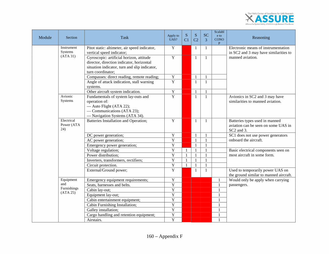
160 – Appendix F
Module Section Task Apply to UAS?
SC1
SC2
SC3
Scalable to
CONOP
Reasoning
Instrument Systems (ATA 31)
Pitot static: altimeter, air speed indicator, vertical speed indicator;
Y
1 1
Electronic means of instrumentation in SC2 and 3 may have similarities to manned aviation.
Gyroscopic: artificial horizon, attitude director, direction indicator, horizontal situation indicator, turn and slip indicator, turn coordinator;
Y
1 1
Compasses: direct reading, remote reading; Y
1 1
Angle of attack indication, stall warning systems.
Y
1 1
Other aircraft system indication. Y
1 1
Avionic Systems
Fundamentals of system lay-outs and operation of: — Auto Flight (ATA 22); — Communications (ATA 23); — Navigation Systems (ATA 34).
Y
1 1
Avionics in SC2 and 3 may have similarities to manned aviation.
Electrical Power (ATA 24)
Batteries Installation and Operation; Y
1 1
Batteries types used in manned aviation can be seen on some UAS in SC2 and 3.
DC power generation; Y
1 1
SC1 does not use power generators onboard the aircraft.
AC power generation; Y
1 1
Emergency power generation; Y
1 1
Voltage regulation; Y 1 1 1
Basic electrical components seen on most aircraft in some form.
Power distribution; Y 1 1 1
Inverters, transformers, rectifiers; Y 1 1 1
Circuit protection. Y 1 1 1
External/Ground power; Y
1 1
Used to temporarily power UAS on the ground similar to manned aircraft.
Equipment and Furnishings (ATA 25)
Emergency equipment requirements; Y
1 Would only be apply when carrying passengers.
Seats, harnesses and belts. Y
1 Cabin lay-out; Y
1
Equipment lay-out; Y
1 Cabin entertainment equipment; Y
1
Cabin Furnishing Installation; Y
1 Galley installation; Y
1
Cargo handling and retention equipment; Y
1 Airstairs. Y
1
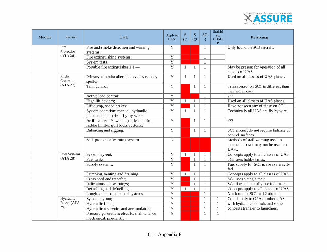
161 – Appendix F
Module Section Task Apply to UAS?
SC1
SC2
SC3
Scalable to
CONOP
Reasoning
Fire Protection (ATA 26)
Fire and smoke detection and warning systems;
Y
1
Only found on SC3 aircraft.
Fire extinguishing systems; Y
1
System tests. Y
1
Portable fire extinguisher 1 1 — Y 1 1 1
May be present for operation of all classes of UAS.
Flight Controls (ATA 27)
Primary controls: aileron, elevator, rudder, spoiler;
Y 1 1 1
Used on all classes of UAS planes.
Trim control; Y
1 1
Trim control on SC1 is different than manned aircraft.
Active load control; Y
1
??? High lift devices; Y 1 1 1
Used on all classes of UAS planes.
Lift dump, speed brakes; Y
1 1
Have not seen any of these on SC1. System operation: manual, hydraulic, pneumatic, electrical, fly-by-wire;
Y 1 1 1
Technically all UAS are fly by wire.
Artificial feel, Yaw damper, Mach trim, rudder limiter, gust locks systems;
Y
1 1
???
Balancing and rigging; Y
1 1
SC1 aircraft do not require balance of control surfaces.
Stall protection/warning system. N
Methods of stall warning used in manned aircraft may not be used on UAS..
Fuel Systems (ATA 28)
System lay-out; Y 1 1 1
Concepts apply to all classes of UAS Fuel tanks; Y
1 1
SC1 uses hobby tanks.
Supply systems; Y
1 1
Fuel supply for SC1 is always gravity fed.
Dumping, venting and draining; Y 1 1 1
Concepts apply to all classes of UAS. Cross-feed and transfer; Y
1 1
SC1 uses a single tank.
Indications and warnings; Y
1 1
SC1 does not usually use indicators. Refuelling and defuelling; Y 1 1 1
Concepts apply to all classes of UAS.
Longitudinal balance fuel systems. Y
1
Not found in SC1 and 2 aircraft. Hydraulic Power (ATA 29)
System lay-out; Y
1 1 Could apply to OPA or other UAS with hydraulic controls and some concepts transfer to launchers.
Hydraulic fluids; Y
1 1 Hydraulic reservoirs and accumulators; Y
1 1
Pressure generation: electric, maintenance mechanical, pneumatic;
Y
1 1

162 – Appendix F
Module Section Task Apply to UAS?
SC1
SC2
SC3
Scalable to
CONOP
Reasoning
Emergency pressure generation; Y
1 1 Pressure Control; Y
1 1
Power distribution; Y
1 1 Indication and warning systems; Y
1 1
Interface with other systems. Y
1 1 Ice and Rain Protection (ATA 30)
Ice formation, classification and detection; Y
1
Ice and rain protection systems only found on SC3 aircraft.
Anti-icing systems: electrical, hot air and chemical;
Y
1
De-icing systems: electrical, hot air, pneumatic and chemical;
Y
1
Rain repellant; Y
1
Probe and drain heating. Y
1
Wiper systems Y
1
Landing Gear (ATA 32)
Construction, shock absorbing; Y
1 1
SC1 gear are built from hobby parts usually.
Extension and retraction systems: normal and emergency;
Y
1 1
Indications and warning; Y
1 1
Wheels, brakes, antiskid and autobraking; Y
1 1
Tyres; Y
1 1
Steering. Y
1 1
Lights (ATA 33)
External: navigation, anti-collision, landing, taxiing, ice;
Y
1 1
SC1 rarely use conventional lighting.
Internal: cabin, cockpit, cargo; Y
1 1
Emergency. Y
1 1
Oxygen (ATA 35)
System lay-out: cockpit, cabin; Y
1 Would only be apply when carrying passengers.
Sources, storage, charging and distribution; Y
1 Supply regulation; Y
1
Indications and warnings; Y
1 Pneumatic/Vacuum (ATA 36)
System lay-out; Y
1 1
May be used to drive components of SC3 and concepts may transfer to pneumatic launchers in SC2.
Sources: engine/APU, compressors, reservoirs, ground supply;
Y
1 1
Pressure control; Y
1 1
Distribution; Y
1 1
Indications and warnings; Y
1 1
Interfaces with other systems. Y
1 1
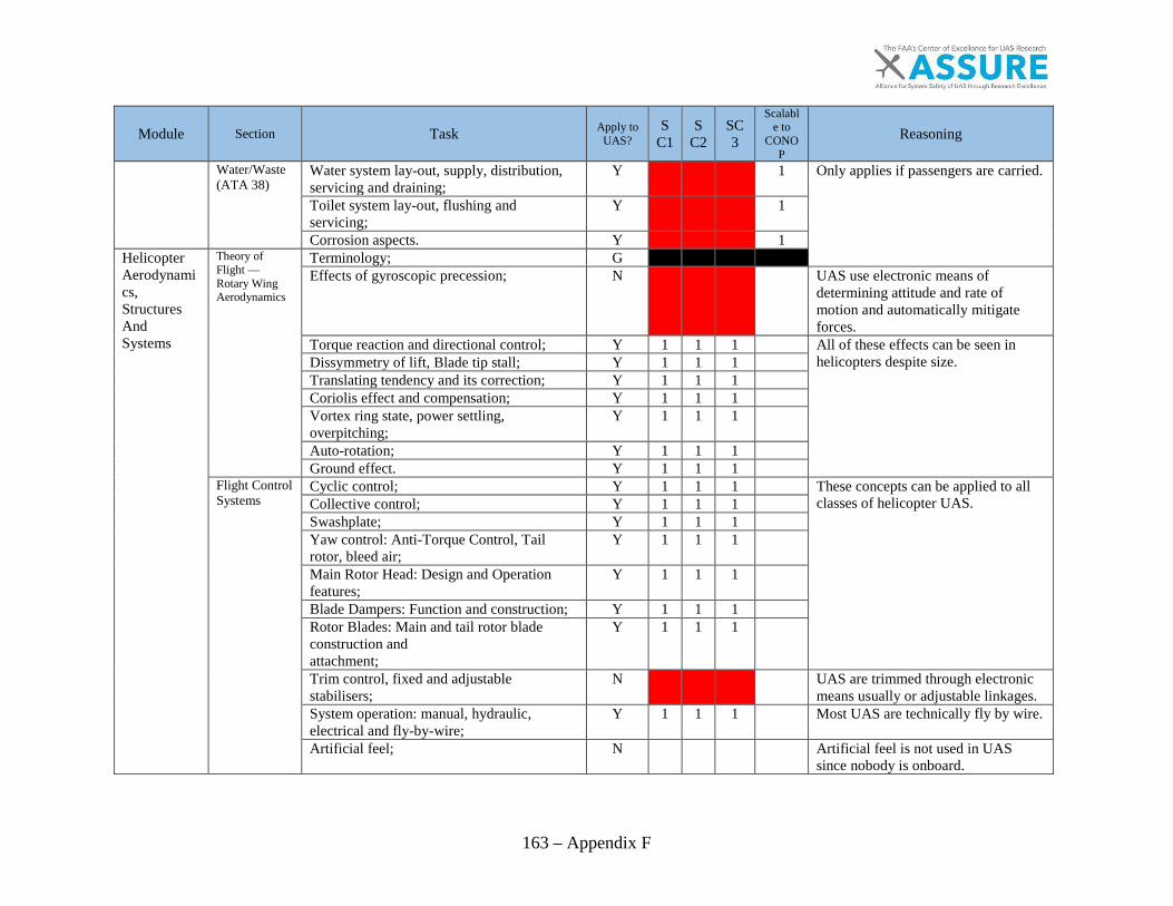
163 – Appendix F
Module Section Task Apply to UAS?
SC1
SC2
SC3
Scalable to
CONOP
Reasoning
Water/Waste (ATA 38)
Water system lay-out, supply, distribution, servicing and draining;
Y
1 Only applies if passengers are carried.
Toilet system lay-out, flushing and servicing;
Y
1
Corrosion aspects. Y
1 Helicopter Aerodynamics, Structures And Systems
Theory of Flight — Rotary Wing Aerodynamics
Terminology; G
Effects of gyroscopic precession; N
UAS use electronic means of determining attitude and rate of motion and automatically mitigate forces.
Torque reaction and directional control; Y 1 1 1
All of these effects can be seen in helicopters despite size.
Dissymmetry of lift, Blade tip stall; Y 1 1 1
Translating tendency and its correction; Y 1 1 1
Coriolis effect and compensation; Y 1 1 1
Vortex ring state, power settling, overpitching;
Y 1 1 1
Auto-rotation; Y 1 1 1
Ground effect. Y 1 1 1
Flight Control Systems
Cyclic control; Y 1 1 1
These concepts can be applied to all classes of helicopter UAS.
Collective control; Y 1 1 1
Swashplate; Y 1 1 1
Yaw control: Anti-Torque Control, Tail rotor, bleed air;
Y 1 1 1
Main Rotor Head: Design and Operation features;
Y 1 1 1
Blade Dampers: Function and construction; Y 1 1 1
Rotor Blades: Main and tail rotor blade construction and attachment;
Y 1 1 1
Trim control, fixed and adjustable stabilisers;
N
UAS are trimmed through electronic means usually or adjustable linkages.
System operation: manual, hydraulic, electrical and fly-by-wire;
Y 1 1 1
Most UAS are technically fly by wire.
Artificial feel; N
Artificial feel is not used in UAS since nobody is onboard.
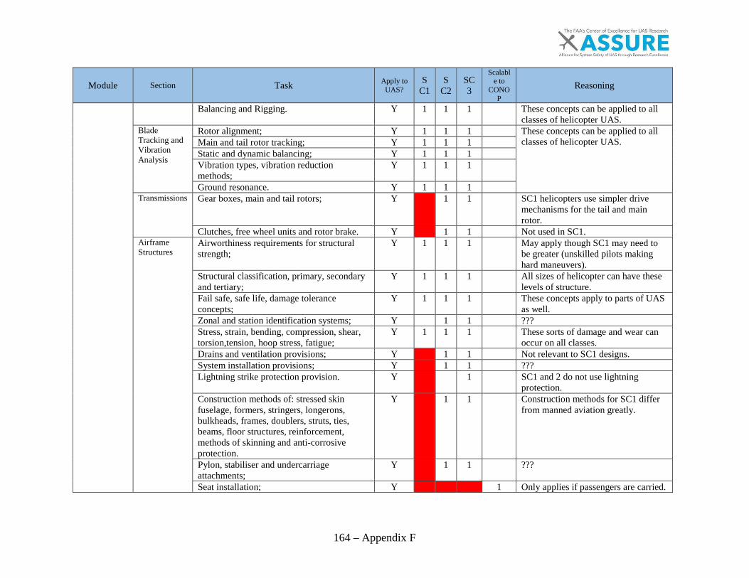
164 – Appendix F
Module Section Task Apply to UAS?
SC1
SC2
SC3
Scalable to
CONOP
Reasoning
Balancing and Rigging. Y 1 1 1
These concepts can be applied to all classes of helicopter UAS.
Blade Tracking and Vibration Analysis
Rotor alignment; Y 1 1 1
These concepts can be applied to all classes of helicopter UAS.
Main and tail rotor tracking; Y 1 1 1
Static and dynamic balancing; Y 1 1 1
Vibration types, vibration reduction methods;
Y 1 1 1
Ground resonance. Y 1 1 1
Transmissions Gear boxes, main and tail rotors; Y
1 1
SC1 helicopters use simpler drive mechanisms for the tail and main rotor.
Clutches, free wheel units and rotor brake. Y
1 1
Not used in SC1. Airframe Structures
Airworthiness requirements for structural strength;
Y 1 1 1
May apply though SC1 may need to be greater (unskilled pilots making hard maneuvers).
Structural classification, primary, secondary and tertiary;
Y 1 1 1
All sizes of helicopter can have these levels of structure.
Fail safe, safe life, damage tolerance concepts;
Y 1 1 1
These concepts apply to parts of UAS as well.
Zonal and station identification systems; Y
1 1
??? Stress, strain, bending, compression, shear, torsion,tension, hoop stress, fatigue;
Y 1 1 1
These sorts of damage and wear can occur on all classes.
Drains and ventilation provisions; Y
1 1
Not relevant to SC1 designs. System installation provisions; Y
1 1
???
Lightning strike protection provision. Y
1
SC1 and 2 do not use lightning protection.
Construction methods of: stressed skin fuselage, formers, stringers, longerons, bulkheads, frames, doublers, struts, ties, beams, floor structures, reinforcement, methods of skinning and anti-corrosive protection.
Y
1 1
Construction methods for SC1 differ from manned aviation greatly.
Pylon, stabiliser and undercarriage attachments;
Y
1 1
???
Seat installation; Y
1 Only applies if passengers are carried.
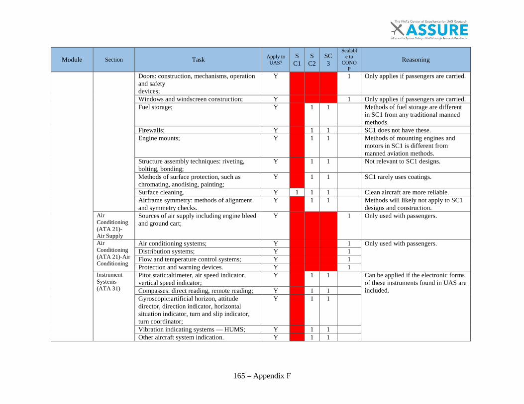
165 – Appendix F
Module Section Task Apply to UAS?
SC1
SC2
SC3
Scalable to
CONOP
Reasoning
Doors: construction, mechanisms, operation and safety devices;
Y
1 Only applies if passengers are carried.
Windows and windscreen construction; Y
1 Only applies if passengers are carried. Fuel storage; Y
1 1
Methods of fuel storage are different in SC1 from any traditional manned methods.
Firewalls; Y
1 1
SC1 does not have these. Engine mounts; Y
1 1
Methods of mounting engines and motors in SC1 is different from manned aviation methods.
Structure assembly techniques: riveting, bolting, bonding;
Y
1 1
Not relevant to SC1 designs.
Methods of surface protection, such as chromating, anodising, painting;
Y
1 1
SC1 rarely uses coatings.
Surface cleaning. Y 1 1 1
Clean aircraft are more reliable. Airframe symmetry: methods of alignment and symmetry checks.
Y
1 1
Methods will likely not apply to SC1 designs and construction.
Air Conditioning (ATA 21)- Air Supply
Sources of air supply including engine bleed and ground cart;
Y
1 Only used with passengers.
Air Conditioning (ATA 21)-Air Conditioning
Air conditioning systems; Y
1 Only used with passengers. Distribution systems; Y
1
Flow and temperature control systems; Y
1 Protection and warning devices. Y
1
Instrument Systems (ATA 31)
Pitot static:altimeter, air speed indicator, vertical speed indicator;
Y
1 1
Can be applied if the electronic forms of these instruments found in UAS are included.
Compasses: direct reading, remote reading; Y
1 1
Gyroscopic:artificial horizon, attitude director, direction indicator, horizontal situation indicator, turn and slip indicator, turn coordinator;
Y
1 1
Vibration indicating systems — HUMS; Y
1 1
Other aircraft system indication. Y
1 1
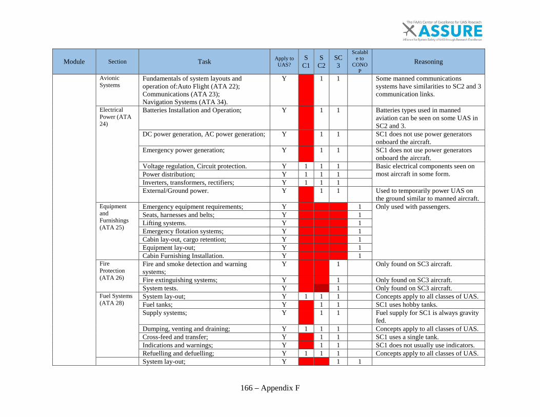
166 – Appendix F
Module Section Task Apply to UAS?
SC1
SC2
SC3
Scalable to
CONOP
Reasoning
Avionic Systems
Fundamentals of system layouts and operation of:Auto Flight (ATA 22); Communications (ATA 23); Navigation Systems (ATA 34).
Y
1 1
Some manned communications systems have similarities to SC2 and 3 communication links.
Electrical Power (ATA 24)
Batteries Installation and Operation; Y
1 1
Batteries types used in manned aviation can be seen on some UAS in SC2 and 3.
DC power generation, AC power generation; Y
1 1
SC1 does not use power generators onboard the aircraft.
Emergency power generation; Y
1 1
SC1 does not use power generators onboard the aircraft.
Voltage regulation, Circuit protection. Y 1 1 1
Basic electrical components seen on most aircraft in some form.
Power distribution; Y 1 1 1
Inverters, transformers, rectifiers; Y 1 1 1
External/Ground power. Y
1 1
Used to temporarily power UAS on the ground similar to manned aircraft.
Equipment and Furnishings (ATA 25)
Emergency equipment requirements; Y
1 Only used with passengers. Seats, harnesses and belts; Y
1
Lifting systems. Y
1 Emergency flotation systems; Y
1
Cabin lay-out, cargo retention; Y
1 Equipment lay-out; Y
1
Cabin Furnishing Installation. Y
1 Fire Protection (ATA 26)
Fire and smoke detection and warning systems;
Y
1
Only found on SC3 aircraft.
Fire extinguishing systems; Y
1
Only found on SC3 aircraft. System tests. Y
1
Only found on SC3 aircraft.
Fuel Systems (ATA 28)
System lay-out; Y 1 1 1
Concepts apply to all classes of UAS. Fuel tanks; Y
1 1
SC1 uses hobby tanks.
Supply systems; Y
1 1
Fuel supply for SC1 is always gravity fed.
Dumping, venting and draining; Y 1 1 1
Concepts apply to all classes of UAS. Cross-feed and transfer; Y
1 1
SC1 uses a single tank.
Indications and warnings; Y
1 1
SC1 does not usually use indicators. Refuelling and defuelling; Y 1 1 1
Concepts apply to all classes of UAS.
System lay-out; Y
1 1
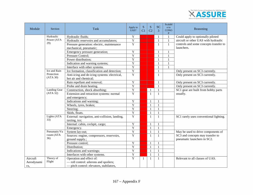
167 – Appendix F
Module Section Task Apply to UAS?
SC1
SC2
SC3
Scalable to
CONOP
Reasoning
Hydraulic Power (ATA 29)
Hydraulic fluids; Y
1 1 Could apply to optionally piloted aircraft or other UAS with hydraulic controls and some concepts transfer to launchers.
Hydraulic reservoirs and accumulators; Y
1 1 Pressure generation: electric, maintenance mechanical, pneumatic;
Y
1 1
Emergency pressure generation; Y
1 1 Pressure Control; Y
1 1
Power distribution; Y
1 1 Indication and warning systems; Y
1 1
Interface with other systems. Y
1 1 Ice and Rain Protection (ATA 30)
Ice formation, classification and detection; Y
1
Only present on SC3 currently. Anti-icing and de-icing systems: electrical, hot air and chemical;
Y
1
Only present on SC3 currently.
Rain repellant and removal; Y
1
Only present on SC3 currently. Probe and drain heating. Y
1
Only present on SC3 currently.
Landing Gear (ATA 32)
Construction, shock absorbing; Y
1 1
SC1 gear are built from hobby parts usually.
Extension and retraction systems: normal and emergency;
Y
1 1
Indications and warning; Y
1 1
Wheels, tyres, brakes; Y
1 1
Steering; Y
1 1
Skids, floats. Y
1 1
Lights (ATA 33)
External: navigation, anti-collision, landing, taxiing, ice;
Y
1 1
SC1 rarely uses conventional lighting.
Internal: cabin, cockpit, cargo; Y
1 1
Emergency. Y
1 1
Pneumatic/Vacuum (ATA 36)
System lay-out; Y
1 1
May be used to drive components of SC3 and concepts may transfer to pneumatic launchers in SC2.
Sources: engine, compressors, reservoirs, ground supply.;
Y
1 1
Pressure control; Y
1 1
Distribution; Y
1 1
Indications and warnings; Y
1 1
Interfaces with other systems. Y
1 1
Aircraft Aerodynamics,
Theory of Flight
Operation and effect of: — roll control: ailerons and spoilers; — pitch control: elevators, stabilators,
Y 1 1 1
Relevant to all classes of UAS.

168 – Appendix F
Module Section Task Apply to UAS?
SC1
SC2
SC3
Scalable to
CONOP
Reasoning
Structures And Systems
variable incidence stabilisers and canards; — yaw control, rudder limiters Control using elevons, ruddervators; Y 1 1 1 Relevant to all classes of UAS. High lift devices: slots, slats, flaps; Y 1 1 1 Relevant to all classes of UAS. Drag inducing devices: spoilers, lift dumpers, speed brakes;
Y
1 1 Never observed on SC1.
Operation and effect of trim tabs, servo tabs, control surface bias.
Y 1 1 Trimming is done differently on SC1.
Speed of sound, subsonic flight, transonic flight, supersonic flight,
Y 1 Only SC3 goes that fast.
Mach number, critical Mach number. Y 1 Only SC3 goes that fast. (c) Rotary Wing Aerodynamics — — 1 Y 1 1 1 Some concepts scale to all sizes of
helicopter. Terminology; G 1 1 1 Operation and effect of cyclic, collective and anti-torque controls.
Y 1 1 1 Some concepts scale to all sizes of helicopters.
Structures — General Concepts
Fundamentals of structural systems. Y 1 1 ??? Zonal and station identification systems; Y 1 1 ??? Electrical bonding; Y
1 Would only work on metal airframes
only found in SC3. Lightning strike protection provision. Y 1 Only found in SC3.
Autoflight (ATA 22)
Fundamentals of automatic flight control including working principles and current terminology
Y 1 1 1 Some concepts may transfer as manned autopilots serve a lot of the same function as unmanned.
Command signal processing; Y 1 1 1 Modes of operation: roll, pitch and yaw channels;
Y 1 1 1
Yaw dampers; Y 1 1 1 Stability Augmentation System in helicopters;
Y 1 1 1
Automatic trim control; Y 1 1 1 Autopilot navigation aids interface; Y 1 1 1 Autothrottle systems. Y 1 1 1

169 – Appendix F
Module Section Task Apply to UAS?
SC1
SC2
SC3
Scalable to
CONOP
Reasoning
Automatic Landing Systems: principles and categories, modes of operation, approach, glideslope, land, go-around, system monitors and failure conditions.
Y 1 1 1
Communication/Navigation (ATA 23/34)
Fundamentals of radio wave propagation, antennas, transmission lines, communication, receiver and transmitter;
Y
These concepts apply to all classes of UAS which use radio to communicate with the operator.
Working principles of following systems: — Very High Frequency (VHF) communication; — High Frequency (HF) communication; — Audio; — Emergency Locator Transmitters; — Cockpit Voice Recorder; — Very High Frequency omnidirectional range (VOR); — Automatic Direction Finding (ADF); — Instrument Landing System (ILS); — Microwave Landing System (MLS); — Flight Director systems; Distance Measuring Equipment (DME); — Very Low Frequency and hyperbolic navigation (VLF/Omega); — Doppler navigation; — Area navigation, RNAV systems; — Flight Management Systems; — Global Positioning System (GPS), Global Navigation Satellite Systems (GNSS); — Inertial Navigation System; — Air Traffic Control transponder, secondary surveillance radar; — Traffic Alert and Collision Avoidance System (TCAS); — Weather avoidance radar; — Radio altimeter; — ARINC communication and reporting
Y
1 The relevance of each of the listed devices will depend on the equipment installed in the UAS.
Electrical Power (ATA 24)
Batteries Installation and Operation; Y
1 1
Batteries types used in manned aviation can be seen on some UAS in SC2 and 3.
DC power generation; Y
1 1
SC1 does not use power generators onboard the aircraft. AC power generation; Y
1 1
Emergency power generation; Y
1 1
Voltage regulation; Y 1 1 1
Basic electrical components seen on most aircraft in some form. Power distribution; Y 1 1 1

170 – Appendix F
Module Section Task Apply to UAS?
SC1
SC2
SC3
Scalable to
CONOP
Reasoning
Inverters, transformers, rectifiers; Y 1 1 1
Circuit protection; Y 1 1 1
External/Ground power. Y
1 1
Used to temporarily power UAS on the ground similar to manned aircraft.
Equipment and Furnishings (ATA 25)
Electronic emergency equipment requirements;
Y
1 Only applies if passengers are carried.
Cabin entertainment equipment. Y
1 Only applies if passengers are carried.
Flight Controls (ATA 27)
Primary controls: aileron, elevator, rudder, spoiler;
Y 1 1 1
Used on all classes of UAS planes.
Trim control; Y
1 1
Trim control on SC1 is different than manned aircraft.
Active load control; Y
1
??? High lift devices; Y 1 1 1
Used on all classes of UAS planes.
Lift dump, speed brakes; Y
1 1
Have not seen any of these on SC1. System operation: manual, hydraulic, pneumatic;
Y
1
Might apply to some SC3 and OPA aircraft.
Artificial feel, Yaw damper, Mach trim, rudder limiter, gust locks.
Y
1 1
???
Stall protection systems. N
Methods of stall warning used in manned aircraft are not the same as unmanned.
System operation: electrical, fly by wire. Y 1 1 1
All UAS are fly by wire in some sense.
Instrument Systems (ATA 31)
Classification; Y
1 1
Concepts would apply to some electronic sensors or methods of measuring on some UAS other than SC1 which uses smaller/different sensors.
Atmosphere; Y
1 1
Terminology; Y
1 1
Pressure measuring devices and systems; Y
1 1
Pitot static systems; Y
1 1
Altimeters; Y
1 1
Vertical speed indicators; Y
1 1
Airspeed indicators; Y
1 1
Machmeters; Y
1 1
Altitude reporting/alerting systems; Y
1 1
Air data computers; Y
1 1

171 – Appendix F
Module Section Task Apply to UAS?
SC1
SC2
SC3
Scalable to
CONOP
Reasoning
Instrument pneumatic systems; Y
1 1
Direct reading pressure and temperature gauges;
Y
1 1
Temperature indicating systems; Y
1 1
Fuel quantity indicating systems; Y
1 1
Gyroscopic principles; Y
1 1
Artificial horizons; Y
1 1
Slip indicators; Y
1 1
Directional gyros; Y
1 1
Ground Proximity Warning Systems; Y
1 1
Compass systems; Y
1 1
Flight Data Recording systems; Y
1 1
Electronic Flight Instrument Systems; Y
1 1
Instrument warning systems including master warning systems and centralised warning panels;
Y
1 1
Stall warning systems and angle of attack indicating systems;
Y
1 1
Vibration measurement and indication. Y
1 1
On board Maintenance Systems (ATA 45)
Central maintenance computers; N
Maintenance data is often on the CS or in a separate computer not onboard.
Data loading system; N
Electronic library system; N
Printing; N
Structure monitoring (damage tolerance monitoring).
N
Propulsion Turbine Engines
Constructional arrangement and operation of turbojet, turbofan, turboshaft and turbopropeller engines;
Y
1
Turbines engines are only found on SC3.
Electronic Engine control and fuel metering systems (FADEC).
Y
1
Turbines engines are only found on SC3.
Engine Indicating Systems
Exhaust gas temperature/Interstage turbine temperature systems;
Y
1 1
Not measured on SC1 aircraft.
Engine speed; Y 1 1 1
All classes can use a form of RPM indicating.
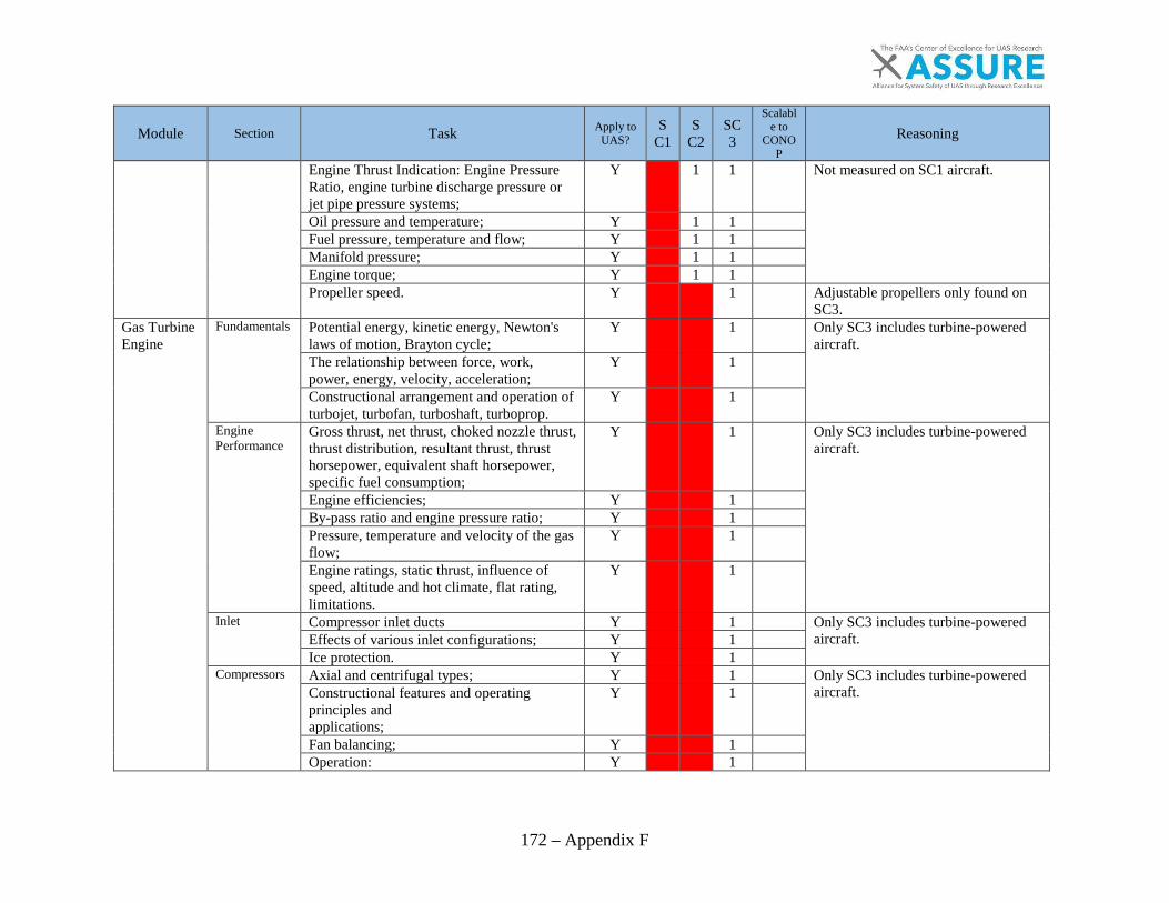
172 – Appendix F
Module Section Task Apply to UAS?
SC1
SC2
SC3
Scalable to
CONOP
Reasoning
Engine Thrust Indication: Engine Pressure Ratio, engine turbine discharge pressure or jet pipe pressure systems;
Y
1 1
Not measured on SC1 aircraft.
Oil pressure and temperature; Y
1 1
Fuel pressure, temperature and flow; Y
1 1
Manifold pressure; Y
1 1
Engine torque; Y
1 1
Propeller speed. Y
1
Adjustable propellers only found on SC3.
Gas Turbine Engine
Fundamentals Potential energy, kinetic energy, Newton's laws of motion, Brayton cycle;
Y
1
Only SC3 includes turbine-powered aircraft. The relationship between force, work,
power, energy, velocity, acceleration; Y
1
Constructional arrangement and operation of turbojet, turbofan, turboshaft, turboprop.
Y
1
Engine Performance
Gross thrust, net thrust, choked nozzle thrust, thrust distribution, resultant thrust, thrust horsepower, equivalent shaft horsepower, specific fuel consumption;
Y
1
Only SC3 includes turbine-powered aircraft.
Engine efficiencies; Y
1
By-pass ratio and engine pressure ratio; Y
1
Pressure, temperature and velocity of the gas flow;
Y
1
Engine ratings, static thrust, influence of speed, altitude and hot climate, flat rating, limitations.
Y
1
Inlet Compressor inlet ducts Y
1
Only SC3 includes turbine-powered aircraft.
Effects of various inlet configurations; Y
1
Ice protection. Y
1
Compressors Axial and centrifugal types; Y
1
Only SC3 includes turbine-powered aircraft.
Constructional features and operating principles and applications;
Y
1
Fan balancing; Y
1
Operation: Y
1
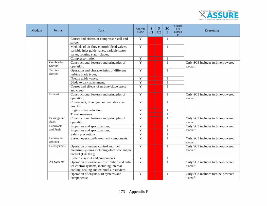
173 – Appendix F
Module Section Task Apply to UAS?
SC1
SC2
SC3
Scalable to
CONOP
Reasoning
Causes and effects of compressor stall and surge;
Y
1
Methods of air flow control: bleed valves, variable inlet guide vanes, variable stator vanes, rotating stator blades;
Y
1
Compressor ratio. Y
1
Combustion Section
Constructional features and principles of operation.
Y
1
Only SC3 includes turbine-powered aircraft. Turbine
Section Operation and characteristics of different turbine blade types;
Y
1
Nozzle guide vanes; Y
1
Blade to disk attachment; Y
1
Causes and effects of turbine blade stress and creep.
Y
1
Exhaust Constructional features and principles of operation;
Y
1
Only SC3 includes turbine-powered aircraft. Convergent, divergent and variable area
nozzles; Y
1
Engine noise reduction; Y
1
Thrust reversers. Y
1
Bearings and Seals
Constructional features and principles of operation.
Y
1
Only SC3 includes turbine-powered aircraft.
Lubricants and Fuels
Properties and specifications; Y
1
Only SC3 includes turbine-powered aircraft.
Properties and specifications; Y
1
Safety precautions. Y
1
Lubrication Systems
System operation/lay-out and components. Y
1
Only SC3 includes turbine-powered aircraft.
Fuel Systems Operation of engine control and fuel metering systems including electronic engine control (FADEC);
Y
1
Only SC3 includes turbine-powered aircraft.
Systems lay-out and components. Y
1
Air Systems Operation of engine air distribution and anti-ice control systems, including internal cooling, sealing and external air services.
Y
1
Only SC3 includes turbine-powered aircraft.
Operation of engine start systems and components;
Y
1
Only SC3 includes turbine-powered aircraft.

174 – Appendix F
Module Section Task Apply to UAS?
SC1
SC2
SC3
Scalable to
CONOP
Reasoning
Starting and Ignition Systems
Ignition systems and components; Y
1
Maintenance safety requirements. Y
1
Engine Indication Systems
Exhaust Gas Temperature/Interstage Turbine Temperature;
Y
1
Only SC3 includes turbine-powered aircraft. Engine Thrust Indication: Engine Pressure
Ratio, engine turbine discharge pressure or jet pipe pressure systems;
Y
1
Oil pressure and temperature; Y
1
Fuel pressure and flow; Y
1
Engine speed; Y
1
Vibration measurement and indication; Y
1
Torque; Y
1
Power. Y
1
Power Augmentation Systems
Operation and applications; Y
1
Only SC3 includes turbine-powered aircraft.
Water injection, water methanol; Y
1
Afterburner systems. Y
1
Turbo-prop Engines
Gas coupled/free turbine and gear coupled turbines;
Y
1
Only SC3 includes turbine-powered aircraft. Reduction gears; Y
1
Integrated engine and propeller controls; Y
1
Overspeed safety devices. Y
1
Turbo-shaft engines
Arrangements, drive systems, reduction gearing, couplings, control systems.
Y
1
Only SC3 includes turbine-powered aircraft.
Auxiliary Power Units (APUs)
Purpose, operation, protective systems. Y
1
Only SC3 includes turbine-powered aircraft.
Powerplant Installation
Configuration of firewalls, cowlings, acoustic panels, engine mounts, anti-vibration mounts, hoses, pipes, feeders, connectors, wiring looms, control cables and rods, lifting points and drains.
Y
1
Only SC3 includes turbine-powered aircraft.
Fire Protection Systems
Operation of detection and extinguishing systems.
Y
1
Only SC3 includes turbine-powered aircraft.
Procedures for starting and ground run-up; Y
1

175 – Appendix F
Module Section Task Apply to UAS?
SC1
SC2
SC3
Scalable to
CONOP
Reasoning
Engine Monitoring and Ground Operation
Interpretation of engine power output and parameters;
Y
1
Only SC3 includes turbine-powered aircraft. Trend (including oil analysis, vibration and
boroscope) monitoring Y
1
Inspection of engine and components to criteria, tolerances and data specified by engine manufacturer;
Y
1
Compressor washing/cleaning; Y
1
Foreign Object Damage. Y
1
Engine Storage and Preservation
Preservation and depreservation for the engine and accessories/systems.
Y
1
Only SC3 includes turbine-powered aircraft.
Piston Engine
Fundamentals Maintenance mechanical, thermal and volumetric efficiencies;
Y 1 1 1
Concepts apply to engines of all sizes.
Operating principles — 2 stroke, 4 stroke, Otto and Diesel;
Y 1 1 1
Concepts apply to engines of all sizes.
Piston displacement and compression ratio; Y 1 1 1
Concepts apply to engines of all sizes. Engine configuration and firing order. Y
1 1
SC1 is almost always a single cylinder.
Engine Performance
Power calculation and measurement; Y
1 1
SC1 is usually not measured for power.
Factors affecting engine power; Y 1 1 1
Important to diagnosing engines. Mixtures/leaning, pre-ignition. Y 1 1 1
Important to diagnosing/tuning engines.
Engine Construction
Crank case, crank shaft, cam shafts, sumps; Y 1 1 1
Present on all UAS classes’ engines. Accessory gearbox; Y
1 1
Not present on SC1 engines.
Cylinder and piston assemblies; Y 1 1 1
Present on all UAS classes’ engines. Connecting rods, inlet and exhaust manifolds;
Y 1 1 1
Present on all UAS classes’ engines.
Valve mechanisms; Y
1 1
SC1 is usually valve less. Propeller reduction gearboxes. Y
1 1
SC1 is always direct drive.
Fuel Systems-Carburetors
Types, construction and principles of operation;
Y
1 1
SC1 carburetors work very differently from larger carburetors.
Icing and heating. Y
1 1
SC1 carburetors work very differently from larger carbs.

176 – Appendix F
Module Section Task Apply to UAS?
SC1
SC2
SC3
Scalable to
CONOP
Reasoning
Fuel Systems-Fuel injection systems
Types, construction and principles of operation.
Y
1 1
SC1 never uses fuel injection.
Fuel Systems-Electronic engine control
Systems lay-out and components. Y
1 1
Not present on SC1 engines. Operation of engine control and fuel metering systems including electronic engine control (FADEC);
Y
1 1
Not present on SC1 engines.
Starting and Ignition Systems
Starting systems, pre-heat systems; Y
1
SC1 and 2 are started externally. Magneto types, construction and principles of operation;
Y
1 1
SC1 does not use magnetos.
Ignition harnesses, spark plugs; Y 1 1 1
Concepts from larger ignition wires and spark plugs apply also to smaller ones.
Low and high tension systems. Y
1 1
??? Induction, Exhaust and Cooling Systems
Construction and operation of: induction systems including alternate air systems;
Y
1 1
SC1 uses very different basic air induction (filter directly on carburetor).
Exhaust systems, engine cooling systems — air and liquid.
Y 1 1 1
SC1 sometimes uses ducting and other methods of air-cooling the engine.
Supercharging/Turbocharging
Principles and purpose of supercharging and its effects on engine parameters;
Y
1
Only found on SC3 powerplants.
Construction and operation of supercharging/turbocharging systems;
Y
1
System terminology; Y
1
Control systems; Y
1
System protection. Y
1
Lubricants and Fuels
Properties and specifications; Y
1 1
SC1 engines use different products as they are often nitromethane.
Fuel additives; Y
1 1
Safety precautions. Y
1 1
Lubrication Systems
System operation/lay-out and components. Y
1 1
SC1 is fuel lubricated.
Engine Indication Systems
Engine speed; Y 1 1 1
All classes can use a form of RPM indicating.
Cylinder head temperature; Y
1 1
Not found on SC1 systems. Coolant temperature; Y
1 1
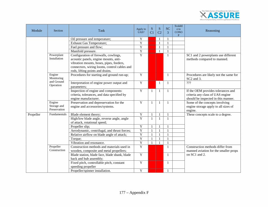
177 – Appendix F
Module Section Task Apply to UAS?
SC1
SC2
SC3
Scalable to
CONOP
Reasoning
Oil pressure and temperature; Y
1 1
Exhaust Gas Temperature; Y
1 1
Fuel pressure and flow; Y
1 1
Manifold pressure. Y
1 1
Powerplant Installation
Configuration of firewalls, cowlings, acoustic panels, engine mounts, anti-vibration mounts, hoses, pipes, feeders, connectors, wiring looms, control cables and rods, lifting points and drains.
Y
1
SC1 and 2 powerplants use different methods compared to manned.
Engine Monitoring and Ground Operation
Procedures for starting and ground run-up; Y
1
Procedures are likely not the same for SC2 and 3.
Interpretation of engine power output and parameters;
Y
1 1
???
Inspection of engine and components: criteria, tolerances, and data specified by engine manufacturer.
Y 1 1 1
If the OEM provides tolerances and criteria any class of UAS engine should be inspected in this manner.
Engine Storage and Preservation
Preservation and depreservation for the engine and accessories/systems.
Y 1 1 1
Some of the concepts involving engine storage apply to all sizes of engine.
Propeller Fundamentals Blade element theory; Y 1 1 1
These concepts scale to a degree. High/low blade angle, reverse angle, angle
of attack, rotational speed; Y 1 1 1
Propeller slip; Y 1 1 1
Aerodynamic, centrifugal, and thrust forces; Y 1 1 1
Relative airflow on blade angle of attack; Y 1 1 1
Torque; Y 1 1 1
Vibration and resonance. Y 1 1 1
Propeller Construction
Construction methods and materials used in wooden, composite and metal propellers;
Y
1
Construction methods differ from manned aviation for the smaller props on SC1 and 2.
Blade station, blade face, blade shank, blade back and hub assembly;
Y
1
Fixed pitch, controllable pitch, constant speeding propeller
Y
1
Propeller/spinner installation. Y
1
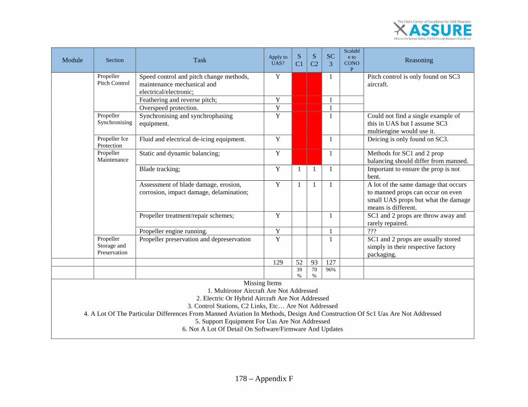
178 – Appendix F
Module Section Task Apply to UAS?
SC1
SC2
SC3
Scalable to
CONOP
Reasoning
Propeller Pitch Control
Speed control and pitch change methods, maintenance mechanical and electrical/electronic;
Y 1
Pitch control is only found on SC3 aircraft.
Feathering and reverse pitch; Y 1 Overspeed protection. Y 1
Propeller Synchronising
Synchronising and synchrophasing equipment.
Y 1 Could not find a single example of this in UAS but I assume SC3 multiengine would use it.
Propeller Ice Protection
Fluid and electrical de-icing equipment. Y 1 Deicing is only found on SC3.
Propeller Maintenance
Static and dynamic balancing; Y 1 Methods for SC1 and 2 prop balancing should differ from manned.
Blade tracking; Y 1 1 1 Important to ensure the prop is not bent.
Assessment of blade damage, erosion, corrosion, impact damage, delamination;
Y 1 1 1 A lot of the same damage that occurs to manned props can occur on even small UAS props but what the damage means is different.
Propeller treatment/repair schemes; Y 1 SC1 and 2 props are throw away and rarely repaired.
Propeller engine running. Y 1 ??? Propeller Storage and Preservation
Propeller preservation and depreservation Y 1 SC1 and 2 props are usually stored simply in their respective factory packaging.
129 52 93 127
39%
70%
96%
Missing Items 1. Multirotor Aircraft Are Not Addressed
2. Electric Or Hybrid Aircraft Are Not Addressed3. Control Stations, C2 Links, Etc… Are Not Addressed
4. A Lot Of The Particular Differences From Manned Aviation In Methods, Design And Construction Of Sc1 Uas Are Not Addressed5. Support Equipment For Uas Are Not Addressed
6. Not A Lot Of Detail On Software/Firmware And Updates

A.5 UAS Maintenance, Modification, Repair, Inspection, Training, and Certification Considerations
TASK 4C: DEVELOP MAINTENANCE TECHNICIAN TRAINING REQUIREMENTS:
In-Depth Analysis of Areas that Require Special Considerations
I. Non-metallic material structures II. Ground control stations and support equipment
III. Communication links IV. Software and autopilots V. Others identified in Task 4b
ii
NOTICE
This document is disseminated under the sponsorship of the U.S. Department of Transportation in the interest of information exchange. The U.S. Government assumes no liability for the contents or use thereof. The U.S. Government does not endorse products or manufacturers. Trade or manufacturers’ names appear herein solely because they are considered essential to the objective of this report. The findings and conclusions in this report are those of the author(s) and do not necessarily represent the views of the funding agency. This document does not constitute FAA policy. Consult the FAA sponsoring organization listed on the Technical Documentation page as to its use.

iii
Legal Disclaimer: The FAA has sponsored this project through the Center of Excellence for Unmanned Aircraft Systems. However, the agency neither endorses nor rejects the findings of this research. The presentation of this information is in the interest of invoking technical comment on the results and conclusions of the research.
iv
Technical Report Documentation Page
Title: A.5 UAS Maintenance, Modification, Repair, Inspection, Training, and Certification Considerations, Non-Metallic Materials Report Date: 6 November 2017 Performing Organizations: Montana State University (MSU) Authors: Kyle Rohan, Douglas Cairns, Femi Ibitoye
Performing Organization Address: Montana State University (MSU) 211 Montana Hall Bozeman, MT 59717
Sponsoring Agency Name and Address: U.S. Department of Transportation Federal Aviation Administration Washington, DC 20591

v
EXECUTIVE SUMMARY ........................................................................................................ XIV
1. INTRODUCTION ...................................................................................................................... 1
1.1. Background ........................................................................................................................ 1 1.2. Overview of Risk Classes .................................................................................................. 3 1.3. Overview of Construction Methods Based on Risk Class ................................................. 5
1.3.1. Class I........................................................................................................................ 6 1.3.2. Class II ...................................................................................................................... 9 1.3.3. Class III ................................................................................................................... 10 1.3.4. Class IV ................................................................................................................... 12 1.3.5. Class V .................................................................................................................... 12 1.3.6. sUAS under CFR Part 107 ...................................................................................... 13
1.4. Operational Considerations .............................................................................................. 15 1.5. Replacement Parts ............................................................................................................ 16 1.6. Supply Chain Considerations ........................................................................................... 17
2. DOCUMENTATION FOR TRAINING AND REPAIRS ......................................................... 18
2.1. Overview of Document Types and Groups ...................................................................... 18 2.1.1. Order 8130.34C ....................................................................................................... 21 2.1.2. AC 20-107B Composite Manufacturing ................................................................. 21 2.1.3. Appropriate 14 CRF Parts to the Repair and Maintenance of UAS ....................... 22 2.1.4. DOT/FAA/AR-00/446 Repair of Composite Laminates ........................................ 22 2.1.5. DOT/FAA/AR-03/53 Effects of Surface Preparation on Long-term Durability of Adhesively Bonded Composite Joints .............................................................................. 23
2.2. Industry Standards ........................................................................................................... 24 2.2.1. SAE Standards ........................................................................................................ 24 2.2.2. ASTM F-38 Unmanned Aircraft Systems ............................................................... 25 2.2.3. ASTM F-37 Light Sport Aircraft ............................................................................ 26
2.3. Published Literature ......................................................................................................... 26 2.3.1. Training of Personnel for Maintenance and Repair of Non-Metallic Materials ..... 26 2.3.2. Repair of Composite Materials ............................................................................... 27 2.3.3. Repair of Thermoplastic Materials ......................................................................... 28 2.3.4. Key Differences of Thermosets and Thermoplastics .............................................. 30 2.3.5. Cleanliness of Surface Prior to Bonding ................................................................. 30
2.4. Current Practices for Repair of a UAS ............................................................................ 33
3. DAMAGE AND INSPECTION OF NON-METALLIC MATERIALS ................................... 34
3.1. Determination of Extent of Damage ................................................................................ 34 3.1.1. Ultrasonic Inspection .............................................................................................. 35 3.1.2. Tap Testing .............................................................................................................. 35 3.1.3. Visual Inspection ..................................................................................................... 35

vi
3.1.4. Additional Damage Inspection Types ..................................................................... 35 3.2. General Preflight Inspection ............................................................................................ 35
3.2.1. Disposition after Inspection .................................................................................... 36
4. CURRENT REPAIR METHODS ............................................................................................. 37
4.1. Current Processes for Repair of UAS .............................................................................. 38 4.2. Repair of Thermosets ....................................................................................................... 39
4.2.1. Material Removal.................................................................................................... 39 4.2.2. Drilling of Thermoset Composite Holes ................................................................. 42 4.2.3. Bolted Repairs ......................................................................................................... 42 4.2.4. Preparation for Bonding .......................................................................................... 43 4.2.5. Filler Material Repairs ............................................................................................ 43 4.2.6. Composite Layup and Orientation .......................................................................... 43 4.2.7. Application of Vacuum ........................................................................................... 44
4.3. Repair of Thermoplastics ................................................................................................. 44 4.3.1. Specialized Equipment for Non-Metallic Repair .................................................... 46 4.3.2. Application of Heat for the Curing of Thermosetting Materials ............................. 47
4.4. Diversity of Repairs ......................................................................................................... 48 4.5. Inspection and Damage Methods ..................................................................................... 48
4.5.1. Thermoplastics ........................................................................................................ 54 4.5.2. Thermosets .............................................................................................................. 54
4.6. Material Removal............................................................................................................. 56 4.6.1. Thermoplastics ........................................................................................................ 56 4.6.2. Thermosets .............................................................................................................. 56
4.7. Surface Preparation .......................................................................................................... 56 4.7.1. Thermoplastics ........................................................................................................ 56 4.7.2. Thermosets .............................................................................................................. 56
4.8. Material Replacement and Testing ................................................................................... 57 4.8.1. Thermoplastics ........................................................................................................ 57 4.8.2. Fiber Reinforced Thermosetting Polymer Repair ................................................... 57
4.9. Post-Repair Inspection for Continued Use ...................................................................... 62 4.9.1. Thermoplastics ........................................................................................................ 62 4.9.2. Thermosets .............................................................................................................. 62
5. RECOMMENDATIONS .......................................................................................................... 63
5.1. Maintenance Training Requirements ............................................................................... 63 5.1.1. Thermoplastics ........................................................................................................ 63 5.1.2. Thermosets .............................................................................................................. 63 5.1.3. sUAS Part 107......................................................................................................... 63
5.2. Practical and Knowledge Test Standards for Non-Metallic Structures ............................ 66 5.2.1. Class I...................................................................................................................... 67 5.2.2. Class II, III .............................................................................................................. 68 5.2.3. Class IV, V .............................................................................................................. 69 5.2.4. Small Unmanned Systems ...................................................................................... 69

vii
5.3. Return To Service Requirements ..................................................................................... 69 5.3.1. Class I...................................................................................................................... 69 5.3.2. Class II, III .............................................................................................................. 70 5.3.3. Class IV, V .............................................................................................................. 70
5.4. Technical Documentation Requirements ......................................................................... 70 5.4.1. Class I...................................................................................................................... 70 5.4.2. Class II, III .............................................................................................................. 70 5.4.3. Class IV, V .............................................................................................................. 71 5.4.4. Additional Recommendations ................................................................................. 71
6. SUMMARY AND CONCLUSIONS ........................................................................................ 72
7. FUTURE WORK ...................................................................................................................... 74
REFERENCES ............................................................................................................................. 78
APPENDICES .............................................................................................................................. 90
Appendix A: ASSURE Project Tasks, Timeframe, and Cost Structure ........................... 91 Appendix B: A Similar Repair Scheme ........................................................................... 93 Appendix C: Example List of Section 333 Repair Exemptions ...................................... 97
viii
1. Fatality Probabilities from Kinetic Energy ....................................................... 4
2. Kinetic Energy Relationship to UAS Size and Risk ......................................... 5
3. Structural Construction Methods of Non-Metallic Materials ........................... 6
4. DJI Phantom 4 Operation Details ..................................................................... 7
5. senseFLY eBee Operational Details .................................................................. 8
6. DJI Inspire 1 Operational Details ..................................................................... 9
7. RQ-11 A/B Raven Operational Details ........................................................... 10
8. Boeing Insitu Scan Eagle Operational Details ................................................ 11
9. RQ-7B v2 Shadow Operational Details .......................................................... 12
10. RQ4 Global Hawk Block 20 Operational Specifications ............................... 13
11. FAA Documents Related to Composite Repair for Type CertifiedAircraft ............................................................................................................ 18
12. List of SAE documents related to composite repair ....................................... 24
13. Currently Published ASTM Standards Relevant to UAS SystemsRepair .............................................................................................................. 25
14. Methods of Energy Application for Fusion Bonding [40] .............................. 29
15. Virgin thermoplastic material properties......................................................... 30
16. Methods for measuring surface cleanliness [101] .......................................... 31
17. Direct methods for measuring surface contamination [101] ........................... 32
18. Relative Properties of Thermoplastic Materials in Unmanned Aircraft[139] ................................................................................................................ 47
19. Related Advisory Circulars to Replacement of Parts ...................................... 64
20. Practical and knowledge test standards for thermoset materials .................... 66
21. Practical and knowledge test standards for thermoplastic materials .............. 67
22. Common areas to inspect for damage ............................................................. 68

ix
23. Non-Metallic UAS Structural Repair Evaluation Matrix ............................... 76
24. ASSURE Project Tasks, Timeframe, and Cost Structure ................................ 92
25. UAS Section 333 Exemptions Between August 2014 and April 2015 ........... 99

x
Figure Page
26. Integration map of UAS into NAS [22] ............................................................ 3
27. DJI Phantom 4................................................................................................... 7
28. senseFly SA eBee .............................................................................................. 8
29. DJI Inspire ......................................................................................................... 9
30. RQ-11A/B Raven ............................................................................................ 10
31. Boeing Insitu Scan Eagle ................................................................................ 11
32. RQ-7B v2 Shadow .......................................................................................... 12
33. Northrop Grumman RQ-4 Global Hawk Block 20 Variant ............................ 13
34. DJI Inspire 1 Rotor.......................................................................................... 14
35. Carbon Fiber sUAS Blades for Phantom 4 ..................................................... 15
36. Effect of failure load on scarf angle from AR00-46 [59] ................................ 23
37. Description of damage in AC20-107 [10] ....................................................... 27
38. Typical Layup for Composite Scarf Joint [124] ............................................. 37
39. Loading Conditions for a Bonded Joint [114] ................................................ 38
40. Adhesive Failure Modes in Composite Materials [114] ................................. 38
41. Use of a 2” disc sander with 180 grit Al203 grit sandpaper forfiberglass epoxy removal ................................................................................ 41
42. Stone deburring die grinder ............................................................................ 41
43. Adhesive flap wheel and a die grinder ............................................................ 41
44. Alcoa HuckMAX systems .............................................................................. 42
45. A step by step process of a non-metallic repair [132] ..................................... 45
46. Polyvance fusion welding system ................................................................... 46
47. Primary inspection points in which damage would require replacement ....... 49
xi
48. Tamper-proof indication stickers .................................................................... 49
49. Overall damage to the thermoplastic structure after impact ........................... 50
50. Small levels of cracking at stress concentrations ............................................ 50
51. Buckling damage ............................................................................................ 51
52. Significant unrepairable damage substantiates replacement ........................... 52
53. Buckling of the battery case and cracking of rotor arms ................................ 52
54. Pullout damage at a fastener (motor mount) ................................................... 53
55. Insert Separation ............................................................................................. 53
56. Damage from a DJI Phantom 3 Impact on a Piper Cherokee w/ STOL cuff .................................................................................................................. 54
57. - Figure 30 is ongoing. .................................................................................... 54
58. 1. Stress Concentration Location of Composite Arm for sUAS ..................... 55
59. 1. Close-up of Damaged Composite Arm from a sUAS, DJI Inspire 1 .......... 55
60. The use of a vacuum bag to repair damaged material .................................... 58
61. Flush repair with no overplies......................................................................... 58
62. Overply fiberglass repair of a composite structure ......................................... 59
63. Digital Image Correlation Setup [35] ............................................................. 59
64. Indication of insufficient shear strength ......................................................... 60
65. Strain concentrations of a repaired system with no overplies ......................... 60
66. Minor Damage of Thin Carbon Epoxy Laminate ........................................... 94
67. Substantial Composite Damage to a Carbon Composite Tube ....................... 94
68. Initial Damage to a Composite Frame [157] ................................................... 95
69. Composite Material Replaced With a Significant Safety Factor .................... 95
70. Composite Finishing to Improve Contour ...................................................... 96
71. Finishing Paint to Protect Surface................................................................... 96
xii
ABS Acrylonitrile Butadiene Styrene AC Advisory Circular AC Advisory Circular AD Airworthiness Directive ADL Acceptable design limits AR Advisory Report ARC Aviation Rulemaking Committee ASI Aviation Safety Inspectors ASTM American Society for Testing of Materials BMI Bismaleimide BVLOS Beyond Visual Line of Sight CACRC Commercial Aircraft Composites Advisory Committee CFR Code of Federal Regulations COA Certificate of Authority CONOPS Concept of Operations DAM Dry as Molded DMA Dynamic Mechanical analysis DOT Department of Transportation FAA Federal Aviation Administration FAR Federal Aviation Requirements FSDO Flight Standards District Office JAA Joint Aviation Authority LOS Line of sight MIDO Manufacturing Inspection District Office MSDS Materials Safety Data Sheet NAS National Airspace System ODA Organizational Designation Authority PE Polyethylene PEEK Polyether ether ketone PEI Polyetherimide PIC Pilot in Command PMA Parts Manufacture Approval PP Polypropylene RCTA Radio Technical Communication for Aeronautics RDL Repairable damage limits RH Relative humidity SAE Society of Automotive Engineers SAE Society for Automotive Engineers

xiii
SB Service Bulletins SSH Systems Safety Handbook TC Type certification UAS Unmanned Aircraft System
xiv
EXECUTIVE SUMMARY
This report presents evaluations and recommendations for the maintenance and repair of non-metallic materials commonly used in Unmanned Aircraft Systems (UAS). Multiple classes of unmanned aircraft are accounted for and grouped by size, structural materials, and potential effects on public safety in the event of a system failure. This information may be used to identify and mitigate risk factors associated with the integration of unmanned aircraft systems into the national airspace. The materials and fabrication techniques used for the structural components of an UAS are the result of a balance between cost, desired flight characteristics, and expected load requirements. This leads to the widespread use of lightweight non-metallic materials, such as thermosetting fiber-reinforced polymer (FRP) composite systems and semi-structural injection molded thermoplastics. Due to their high strength-to-weight ratio, FRPs are often used in larger UAS classes, while thermoplastics are common in smaller unmanned systems. Non-metallic materials are used in most of the primary structures of UAS. This is true for fixed wing, rotorcraft, and lighter than air UAS. Consequently, the maintenance and repair of these materials are introduced and discussed in the context of operational safety with respect to specific UAS classifications. The effectiveness of certain repair techniques are investigated. When possible, these procedures are compared to the relevant standards currently established by the FAA for manned aircraft. This report also discusses some of the issues involved when making the decision whether to repair or replace a part, as well as how this decision relates to continued maintenance of the UAS, and to personnel training requirements. Examples of field repairs of non-metallic materials not common to certified aircraft are provided. Inspection methods used for the larger UAS classes are recommended to mirror the current standards used for manned aircraft, while low-cost techniques such as visual and tap testing are reasonable for small UAS (sUAS). The report concludes with suggestions for the further development of best practices for the maintenance and repair of non-metallic materials in unmanned aircraft, including the sourcing of materials, the limitations of repair techniques, risk analysis, and testing criteria.
1
1. INTRODUCTION
There is a significant lack of knowledge and understanding of the initial and continued airworthiness of unmanned aircraft systems (UAS) and how maintenance practices differ from those associated with manned aircraft. Compounding these deficiencies, components that are uniquely associated with UAS, such as ground control stations and communication links, create concerns for ensuring airworthiness. Additionally, aircraft maintenance technician skill sets are different for maintaining UAS than for manned aircraft, especially as it relates to system components and equipment beyond the aircraft itself. This research aims to address those concerns in order to support safe UAS flight operations in the National Airspace System (NAS). The key components of the initial UAS Maintenance, Modification, Repair, Inspection, Training, and Certification Considerations research include: 1) a review of existing data available for maintaining UAS of all sizes; 2) a comparison of existing maintenance data for UAS with the type of data available for manned aircraft; 3) a determination of whether a delineation between different types/sizes of UAS should be developed to establish varying thresholds of maintenance rigor; 4) identification of best practices for maintaining various classes of UAS within the context of their operational environment; 5) compilation of the current training materials and qualifications required for various UAS platforms, and; 6) a recommendation of training and certification requirements for UAS maintenance technicians and repair stations across the spectrum of all UAS classes. These research components build upon prior research in an effort to develop justifiable recommendations to the Federal Administration Association (FAA) on how UAS should be maintained to support the FAA’s plan to integrate UAS into the NAS. This paper represents the first of a comprehensive series of reports tasked with investigating UAS Maintenance, Modification, Repair, Inspection, Training, and Certification Considerations. The current work is designated within the Maintenance, Modification, Repair, Inspection, Training, and Certification Considerations team as Task 4c(i): Repair of Non-Metallic Material Structures. In this report, trial repairs are demonstrated, post-repair inspections are performed and guidelines for the repair of non-metallic materials are provided. When possible, the recommendations for the maintenance and repair of UAS discussed in this report are compared to current manned aviation standards published by the FAA. Other resources for repair methods on non-metallic materials may be found in industry, academic, and government documentation [1-10]. A detailed list of ASSURE Project Tasks, Timeframe, and Cost Structure is provided in Appendix A. Task 4 c(i) represents approximately 13% of the overall project.Appendix AAppendixAAppendix A
1.1. Background
A variety of unmanned aircraft systems are in operation today, from sub-250g micro-drones intended for the UAS enthusiast, to much larger persistent high altitude systems designed for military operations [11]. However, because the structural materials used for each of these extreme examples can be similar, any assessment of risk due to structural failure should be conducted
2
within the context of the specific class of UAS [12]. Recommendations for inspection, maintenance, and repair can be adjusted according to the class of UAS. Inspection techniques on manned aircraft are designed to meet safety standards by minimizing the chance that damage goes unnoticed [13-18]. The level of scrutiny is related to the size and purpose of the aircraft, with greater levels corresponding to the potential risk to human life in the event of failure. A risk profile which correlates the size of an aircraft to the need for greater regulation has been proposed by a number of authors, c.f. [19, 20]. In those studies, the goal was to reduce regulatory burdens while promoting the safety of the skies and the public. Similarly, methods for managing the inspection, maintenance, and repair of unmanned aircraft systems should consider the operational environment, the size of the system, and its construction. In order to meet equivalent levels of safety, any repair to a UAS must satisfy its original as-built requirements. There are currently about 670,000 registered small UAS (sUAS) regulated under FAA Part 107, which is FAA Small Unmanned Regulations, effective August 29, 2016. While this already outnumbers registered manned aircraft, it is projected that approximately 7 million sUAS will be registered by 2020 [21], playing an ever-increasing role in an expanding range of capacities. Therefore, the regulatory methods chosen for UAS should be flexible and scalable. To regulate this expansion and integrate UAS into the NAS, the UAS Advisory and Rulemaking Committee (ARC) report delivered in the fall of 2012 promoted the 10-15 year goal of type certification, as shown in Figure 1. Referenced from the UAS ARC, the integration of unmanned systems into the NAS is described as a percentage of experimental and standardized operations that evolve over time [22], with the intent to reduce the cost of complexity where possible while “establishing a precedent” in which any regulation will help to direct international regulatory activities. This goal was also discussed earlier by Grimsley [20], who expressed the opinion that regulations should “do no harm”, and that there can be no one-size fits all regulation. Currently, exemptions to type certification fall under either Section 333 or the use of an experimental category exemption [23]. As of January 2017, the list of exemptions under Section 333 includes 1401 specific systems [23].

3
Figure 1. Integration map of UAS into NAS [22]
1.2. Overview of Risk Classes
According to the FAA, there are multiple ways of categorizing risk to the general public and the national airspace. There are currently two different regulatory requirements for commercial and general aviation [15]. However, certification processes are not currently defined for unmanned aircraft and their systems. Therefore, it is assumed in this report that the intent of any repair is to return the system to a state equivalent to the original as-manufactured level, and that the risk to a repaired UAS is categorized in the same manner as before damage was incurred. Risk factors related to the repair and maintenance of non-metallic structural components of unmanned systems are considered and recommendations are given to ensure operational safety. The repair procedures described in this report may be useful to define training requirements. Risk mitigation through Non-Destructive Investigation (NDI), damage-tolerant design, and failsafe design methodology is also explored [17, 24-28]. In manned aviation there is an inherent risk to the safety of the operator during every flight, and regulations are designed to minimize this risk. In contrast, in unmanned aviation there is less risk to the pilot in command (PIC), while the risk to the public remains dependent on the PIC’s level of training and the maintenance of the unmanned system. Therefore, PIC training should place significance on understanding proper structural inspection [29, 30]. The approach in this study is to delineate the risk related to damage and repairs to typical non-metallic components used in unmanned aircraft and UAS launch systems. This is an important task for two reasons. First, it is expected that non-metallic materials will continue to comprise a major portion of lower cost UASs [26]. Secondly, unmanned aircraft will need to become highly reliable in order to satisfy the public’s current perception of safety, especially as the NAS becomes busier and UAS usage and number of flight hours logged continues to increase [31].

4
Currently, sUAS systems show greater resemblance to consumer electronics than the safety conscious designs used in manned aviation. They do not take into account structural design and marking requirements of manned aircraft [32]. These small systems represent a large portion of the market share of UAS registrations, but should not be the only airframes considered in the recommendations of non-metallic repair. Structural repair manuals (SRMs) for small unmanned aircraft systems do not currently exist. However, the Advisory Circulars AC 43.12-1B and AC 43-9 provide standard aircraft maintenance procedures for aircraft with a special type certification. In this report, these procedures are reviewed and compared to 14 CFR Part 43 requirements. Risk associated with UAS impact has been studied by an Advisory Research Committee before the initial publication of the Part 107 rule [33]. This is described through the casualty expectation experiments [12, 20]. Currently, UAS are grouped together depending on the type of threat posed. As discussed by Clothier [12], clustering methods based on maximum kinetic energy and total impact area may be used as a flexible criterion in determining the likelihood of an impact causing a fatality. These were selected for their relationship to the abbreviated injury scale (AIS). The probability of fatality from falling debris is defined by the kinetic energy of the system and the position of the ground personnel (see Error! Reference source not found.). Other criteria may also be defined, but that is beyond the scope of this work. To determine risk, the mass and speed of the UAS are separated, similar to the approach of the 14 CFR Part 107 example in which the maximum weight of 55lbs and airspeed of 100 knots is utilized [34]. However, it is noted that the risk classes as defined by Clothier do not align with the Part 107 small UAS (sUAS) regulations, as promulgated in August 2016. As codified, any unmanned aircraft with a max gross weight under 55lbs and a speed under 100 knots fall into the sUAS category.
Table 1. Fatality Probabilities from Kinetic Energy
Body Position Body Area Probability of Fatality (Kinetic Energy, ft*lb)
10% 50% 90% Standing 1.0 31 58 109 Sitting 2.9 41 81 159 Prone 5.1 38 76 152
Source: [12]
The location of operation is an important factor to consider when it comes to the repair and maintenance of these systems. Within each operational environment, risks should be broken down into two segments: operations over non-participants, and operations over unpopulated areas. Operations over non-participants could utilize a greater level of scrutiny for repairs. The study and discussion of operations over people and the hazard created by debris are outside the scope of this report, but were extensively studied by the Space Shuttle Columbia Incident Team and others [35, 36]. However, to put the current risk from falling debris in context, records dating from the years 1964 to 1999 show that about eight people per year were killed by falling debris [35]. Between 1984 and 2000, 2.2% of all aircraft related fatalities were a result of falling debris [20]. This level
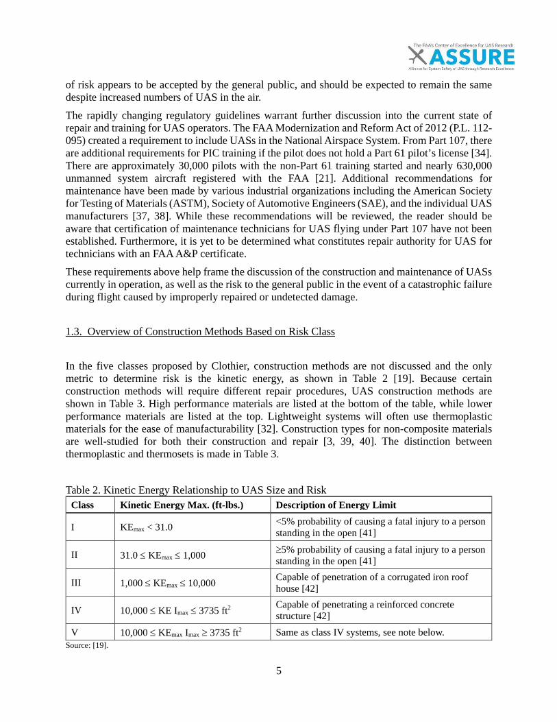
5
of risk appears to be accepted by the general public, and should be expected to remain the same despite increased numbers of UAS in the air. The rapidly changing regulatory guidelines warrant further discussion into the current state of repair and training for UAS operators. The FAA Modernization and Reform Act of 2012 (P.L. 112-095) created a requirement to include UASs in the National Airspace System. From Part 107, thereare additional requirements for PIC training if the pilot does not hold a Part 61 pilot’s license [34].There are approximately 30,000 pilots with the non-Part 61 training started and nearly 630,000unmanned system aircraft registered with the FAA [21]. Additional recommendations formaintenance have been made by various industrial organizations including the American Societyfor Testing of Materials (ASTM), Society of Automotive Engineers (SAE), and the individual UASmanufacturers [37, 38]. While these recommendations will be reviewed, the reader should beaware that certification of maintenance technicians for UAS flying under Part 107 have not beenestablished. Furthermore, it is yet to be determined what constitutes repair authority for UAS fortechnicians with an FAA A&P certificate.These requirements above help frame the discussion of the construction and maintenance of UASs currently in operation, as well as the risk to the general public in the event of a catastrophic failure during flight caused by improperly repaired or undetected damage.
1.3. Overview of Construction Methods Based on Risk Class
In the five classes proposed by Clothier, construction methods are not discussed and the only metric to determine risk is the kinetic energy, as shown in Table 2 [19]. Because certain construction methods will require different repair procedures, UAS construction methods are shown in Table 3. High performance materials are listed at the bottom of the table, while lower performance materials are listed at the top. Lightweight systems will often use thermoplastic materials for the ease of manufacturability [32]. Construction types for non-composite materials are well-studied for both their construction and repair [3, 39, 40]. The distinction between thermoplastic and thermosets is made in Table 3.
Table 2. Kinetic Energy Relationship to UAS Size and Risk Class Kinetic Energy Max. (ft-lbs.) Description of Energy Limit
I KEmax < 31.0 <5% probability of causing a fatal injury to a person standing in the open [41]
II 31.0 ≤ KEmax ≤ 1,000 ≥5% probability of causing a fatal injury to a person standing in the open [41]
III 1,000 ≤ KEmax ≤ 10,000 Capable of penetration of a corrugated iron roof house [42]
IV 10,000 ≤ KE Imax ≤ 3735 ft2 Capable of penetrating a reinforced concrete structure [42]
V 10,000 ≤ KEmax Imax ≥ 3735 ft2 Same as class IV systems, see note below. Source: [19].

6
Note: The distinction between class IV and V is the area of impact, Imax. A class IV system will have impact area less than 3,735 ft. while a class V system will have an impact area greater than 3,735 ft. The risk class is determined by material type. Typically higher performance systems will utilize a greater percentage of composite materials [43]. This classification, along with the size of the UAS when appropriate, is utilized throughout the remainder of the report to help identify proper repair methods and procedures for construction materials and methods common, or even unique, to UASs. For thermoplastics, a filler material may be used to reduce the overall cost of the structure or to add some structural benefit. Table 3 lists most of the common materials for the construction of all sizes of UASs. A mix of materials and processes is used for the lower-class systems and higher-class systems use higher performance materials for their increased properties. Lower classes dominate the current systems in operation for commercial uses [44]. These systems were commercially registered under section 333 exemptions as their low cost makes acquisition and maintenance simpler [44]. However, the current trends may not continue as regulation allows for more unmanned operation into the NAS.
Table 3. Structural Construction Methods of Non-Metallic Materials Type Process Materials Class Thermoplastic (TP) Injection Molded Nylon, PE, PS, ABS I Thermoplastic (TP) Filled Injection Molded Nylon, PE, PS, ABS I-II
Thermosets (TS) Compression molded Carbon(F), FG(F), Aramid (F), EP(M) I-V
Thermosets (TS) Solid laminate prepreg Carbon(F), FG(F), Aramid (F), EP(M) I-V
Thermosets (TS) Sandwich construction Carbon(F), FG(F), EP(M), Adv(M) I-V
Thermoplastic (TP) Compression molded tape
Carbon (F), Nylon, PE, PS, ABS, Adv(M) I-V
The next sections describe the construction techniques for the classes described in Table 3 in greater detail. Throughout this document, the distinction will be made between thermoset and thermoplastic materials, as their repair and maintenance are different in several ways. In general, thermoset composites require more training and care during repair and maintenance than general thermoplastic materials.
1.3.1. Class I
These lightweight systems are a complex mixture of high and low performance materials with a mixture of assembly methods [45]. The most common use of high performance composites is for
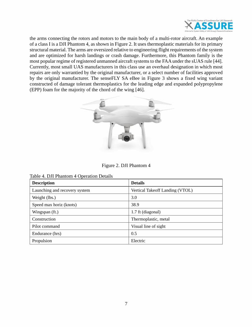
7
the arms connecting the rotors and motors to the main body of a multi-rotor aircraft. An example of a class I is a DJI Phantom 4, as shown in Figure 2. It uses thermoplastic materials for its primary structural material. The arms are oversized relative to engineering flight requirements of the system and are optimized for harsh landings or crash damage. Furthermore, this Phantom family is the most popular regime of registered unmanned aircraft systems to the FAA under the sUAS rule [44]. Currently, most small UAS manufacturers in this class use an overhaul designation in which most repairs are only warrantied by the original manufacturer, or a select number of facilities approved by the original manufacturer. The senseFLY SA eBee in Figure 3 shows a fixed wing variant constructed of damage tolerant thermoplastics for the leading edge and expanded polypropylene (EPP) foam for the majority of the chord of the wing [46].
Figure 2. DJI Phantom 4
Table 4. DJI Phantom 4 Operation Details Description Details Launching and recovery system Vertical Takeoff Landing (VTOL) Weight (lbs.) 3.0 Speed max horiz (knots) 38.9 Wingspan (ft.) 1.7 ft (diagonal) Construction Thermoplastic, metal Pilot command Visual line of sight Endurance (hrs) 0.5 Propulsion Electric

8
Figure 3. senseFly SA eBee
Table 5. senseFLY eBee Operational Details Description Details Launching and recovery system Hand launch/ automatic stall Weight (lbs.) 1.56 Speed max horiz (knots) 48.6 Wingspan (ft.) 3.1 Construction Thermoplastic, EPP foam Pilot command Visual line of sight Endurance (hrs) 0.75 Propulsion Electric

9
1.3.2. Class II
A class II system is much more likely to utilize thermoset composites than a class I system for both fixed wing and rotorcraft. The system may be a commercial low cost or military adaptation. These systems may fall outside the Part 107 regulations for their concept of operations and mass. An example of a class II aircraft would be either the DJI Inspire 1 (Figure 4) as a multi-rotor example or an AeroVironment RQ-11 Raven for a fixed wing system (Figure 5). Their repair documentation varies based on the manufacturer [47].
Figure 4. DJI Inspire
Table 6. DJI Inspire 1 Operational Details Description Details Launching and recovery system Vertical Takeoff Landing (VTOL) Weight (lbs.) 7.71 Speed max horiz (knots) 42 Wingspan (ft.) 2.9 (diagonal) Construction Composite, thermoplastic, metal Pilot command Visual line of sight Endurance (hrs) 0.3 Propulsion Electric
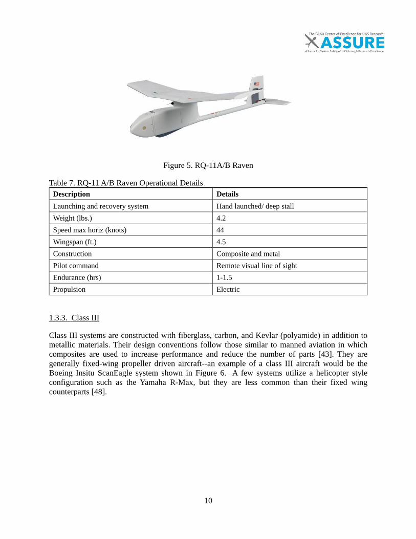
10
Figure 5. RQ-11A/B Raven
Table 7. RQ-11 A/B Raven Operational Details Description Details Launching and recovery system Hand launched/ deep stall Weight (lbs.) 4.2 Speed max horiz (knots) 44 Wingspan (ft.) 4.5 Construction Composite and metal Pilot command Remote visual line of sight Endurance (hrs) 1-1.5Propulsion Electric
1.3.3. Class III
Class III systems are constructed with fiberglass, carbon, and Kevlar (polyamide) in addition to metallic materials. Their design conventions follow those similar to manned aviation in which composites are used to increase performance and reduce the number of parts [43]. They are generally fixed-wing propeller driven aircraft--an example of a class III aircraft would be the Boeing Insitu ScanEagle system shown in Figure 6. A few systems utilize a helicopter style configuration such as the Yamaha R-Max, but they are less common than their fixed wing counterparts [48].

11
Figure 6. Boeing Insitu Scan Eagle
Table 8. Boeing Insitu Scan Eagle Operational Details Description Details Launching and recovery system Pneumatic launch/hook capture Weight (lbs.) 48.5 Speed max horiz (knots) 80 Wingspan (ft.) 10.2 Construction Composite and metal Pilot command Remote visual line of sight Endurance (hrs) 24+ Propulsion Gasoline
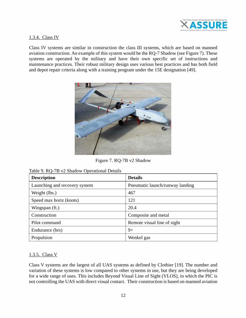
12
1.3.4. Class IV
Class IV systems are similar in construction the class III systems, which are based on manned aviation construction. An example of this system would be the RQ-7 Shadow (see Figure 7). These systems are operated by the military and have their own specific set of instructions and maintenance practices. Their robust military design uses various best practices and has both field and depot repair criteria along with a training program under the 15E designation [49].
Figure 7. RQ-7B v2 Shadow
Table 9. RQ-7B v2 Shadow Operational Details Description Details Launching and recovery system Pneumatic launch/runway landing Weight (lbs.) 467 Speed max horiz (knots) 121 Wingspan (ft.) 20.4 Construction Composite and metal Pilot command Remote visual line of sight Endurance (hrs) 9+ Propulsion Wenkel gas
1.3.5. Class V
Class V systems are the largest of all UAS systems as defined by Clothier [19]. The number and variation of these systems is low compared to other systems in use, but they are being developed for a wide range of uses. This includes Beyond Visual Line of Sight (VLOS), in which the PIC is not controlling the UAS with direct visual contact. Their construction is based on manned aviation
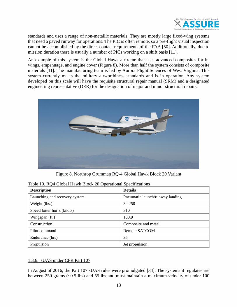
13
standards and uses a range of non-metallic materials. They are mostly large fixed-wing systems that need a paved runway for operations. The PIC is often remote, so a pre-flight visual inspection cannot be accomplished by the direct contact requirements of the FAA [50]. Additionally, due to mission duration there is usually a number of PICs working on a shift basis [11]. An example of this system is the Global Hawk airframe that uses advanced composites for its wings, empennage, and engine cover (Figure 8). More than half the system consists of composite materials [11]. The manufacturing team is led by Aurora Flight Sciences of West Virginia. This system currently meets the military airworthiness standards and is in operation. Any system developed on this scale will have the requisite structural repair manual (SRM) and a designated engineering representative (DER) for the designation of major and minor structural repairs.
Figure 8. Northrop Grumman RQ-4 Global Hawk Block 20 Variant
Table 10. RQ4 Global Hawk Block 20 Operational Specifications Description Details Launching and recovery system Pneumatic launch/runway landing Weight (lbs.) 32,250 Speed loiter horiz (knots) 310 Wingspan (ft.) 130.9 Construction Composite and metal Pilot command Remote SATCOM Endurance (hrs) 35 Propulsion Jet propulsion
1.3.6. sUAS under CFR Part 107
In August of 2016, the Part 107 sUAS rules were promulgated [34]. The systems it regulates are between 250 grams (~0.5 lbs) and 55 lbs and must maintain a maximum velocity of under 100
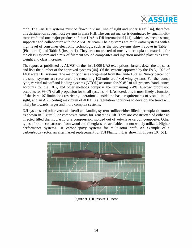
14
mph. The Part 107 systems must be flown in visual line of sight and under 400ft [34], therefore this designation covers most systems in class I-III. The current market is dominated by small multi-rotor craft and one major producer of thee UAS is DJI international [44], which has been a strong supporter and collaborator with the ASSURE team. Their systems are multi-rotor systems with a high level of consumer electronic technology, such as the two systems shown above in Table 4 (Phantom 4) and Table 6 (Inspire 1). They are constructed of mostly thermoplastic materials for the class I system and a mix of filament wound composites and injection molded plastics as size, weight and class increase. The report, as published by AUVSI on the first 1,000 UAS exemptions, breaks down the top sales and lists the number of the approved systems [44]. Of the systems approved by the FAA, 1028 of 1480 were DJI systems. The majority of sales originated from the United States. Ninety percent of the small systems are rotor craft, the remaining 105 units are fixed wing systems. For the launch type, vertical takeoff and landing systems (VTOL) accounts for 89.8% of all systems, hand launch accounts for the ~8%, and other methods comprise the remaining 2.4%. Electric propulsion accounts for 99.6% of all propulsion for small systems [44]. As noted, this is most likely a function of the Part 107 limitations restricting operations outside the basic requirements of visual line of sight, and an AGL ceiling maximum of 400 ft. As regulation continues to develop, the trend will likely be towards larger and more complex systems. DJI systems and other vertical takeoff and landing systems utilize either filled thermoplastic rotors as shown in Figure 9, or composite rotors for generating lift. They are constructed of either an injected filled thermoplastic or a compression molded out of autoclave carbon composite. Other types of rotors constructed from wood and fiberglass are available, but not widely utilized. Higher performance systems use carbon/epoxy systems for multi-rotor craft. An example of a carbon/epoxy rotor, an aftermarket replacement for DJI Phantom 3, is shown in Figure 10. [51].
Figure 9. DJI Inspire 1 Rotor
15
Figure 10. Carbon Fiber sUAS Blades for Phantom 4
1.4. Operational Considerations
The operational environment of a UAS plays a significant role in the risk involved in the aircraft’s operation. Clothier performed risk analysis for the Australian airspace defined as an Equivalent Level of Safety (ELOS) by correlating the casualty risk to the equivalent level of safety between manned and unmanned operations [12]. Additional studies have performed a similar risk assessment, such as the ASTM Standard Practice for Operational Risk Assessment of Small Unmanned Aircraft Systems [29]. The main detracting factors to using mass and speed as a comparison factor include: operational conditions including current flight rules, weather, and the equipment of the aircraft or type of aircraft. Additionally, even if the risk of casualties is low, the number of incidents involving UAS damage could increase to an unacceptable level. These are some of the primary limiting factors for the use of fatality based criteria [19, 46]. Overall, the size and construction of a UAS will determine the risk to general public. The straightforward statement that all risk is not the same and should be managed appropriately is well documented for pilots and repair personnel by the FAA and professional organizations [15, 29] and it should be explicitly stated for unmanned flight as well. A repair technician, like a PIC, should know when they are operating outside their comfort zone. Appropriate decision making and operational skills have a direct carryover from manned aviation for the maintenance, repair, and training for unmanned aircraft. Proper habits should be developed to avoid the “get-home-itis” (when a pilot is rushed, leading to poor aeronautical decision-making and/or poor situational awareness) and poor planning that can lead to incidents and loss of control of an aircraft from improper repair [15]. This risk should be managed appropriately for all sizes of aircraft, but for smaller unmanned aircraft the level of training is less [47]. Therefore, the operators of these small systems should be conditioned to avoid risk when there is any uncertainty of the structural integrity of the system. Small systems operators should be given clear instructions on how to rectify this uncertainty thereby avoiding risky behavior. For small systems, a repair requires different standards than a large system because replacement parts are less expensive than repairing the part. This does not mean that a repair cannot be performed on small systems, but for specific materials,

16
limitations as to the minimum requirements, such as pre-damaged strength levels will apply regardless of size. For larger systems, such as those outside the Part 107 rules or not operating under a general section 333 COA, the requirements for validating repair integrity fits well into the requirements of manned aviation. These requirements would create a system for non-metallic structures, and are much simpler to integrate into the NAS from their relative similarities to manned aviation. Preliminary steps have already been taken in the use of the Experimental category of special airworthiness certificates and the certificates associated with 14 CFR requirements for safe flight [52] These stop-gap measures are temporary if the FAA establishes formal airworthiness certification of UAS.
1.5. Replacement Parts
When not feasible to repair a system due to cost or the inability to restore to an original condition sufficient for operation, the part should be replaced [53, 54] as required under the maintenance regulations of an unmanned aerial system. For critical systems such as rotors and moving parts where weight, balance, flutter and other aero-elastic considerations are critical to intended operation, repair may be very limited or prohibited [13]. The replacement of parts will play a greater role for small systems as the relative cost of replacing the part as compared to an effective non-metallic repair would be difficult to justify. To give an idea of the cost of non-metallic parts for small systems, a composite arm of a DJI Inspire 1 control arm is $64 for the complete arm replacement. The estimated time for a repair would be about three hours at a cost of $300 using the DJI in-house service center [55]. Replacement parts are covered by AC21-45 for the use of commercial parts on Type Certified aircraft [56]. The background section of AC21-45 is relevant to the current state of unmanned repair 3.b. “However, the parts manufacturing authority (PMA) rules have a gap in this area, because there are many articles installed on aircraft that were not specifically designed or produced for sale and installation on type certificated products.” This would need for the system to meet non-structural definitions of the part under 14 CFR § 21.50(c)(2)(i), that “failure of the commercial part as installed in the product, would not degrade the level of safety of the product”. Although this would allow for the use of some replacement parts, the critical functioning aspects of the composite arms on a DJI Inspire 1 would disallow the use of this Advisory Circular (AC) unless modified or amended to cover commercially produced parts for UAS systems that have structural significance on small systems. Approved and unapproved parts for installation are covered by AC 21-29C Detecting and Reporting of Suspected Unapproved Parts. Since UASs do not currently have type certification, this classification would not be appropriate. For the replacement parts of unmanned systems, the current process would be replacement under the manufacturers design data. These are specifically for the small commercial systems. Classes III-V, systems that fall outside Part 107 rules, are more regulated for their certification and for repair. They usually have special airworthiness certificates and should be regulated as such. The replacement of parts is more streamlined to the FAA’s process of repair and these systems will have structural repair manuals [47].
17
1.6. Supply Chain Considerations
The supply chain of a small UAS is more varied and complex than a traditional aerospace manufacturing supply, yet are similar to the B787 procurement structure. This structure has been reported by the Boeing Critical Systems Review Team (CSRT) and their study of the 787 system at the request of the FAA. The supply chain of the 787 is similar to a typical supply chain for consumer level goods and is partially based on the Toyota supply model [57]. This supply environment bears similarity to the current broader procurement process for UAS systems. The final report from the joint Boeing FAA 787-8 (CSRT) report made the following recommendations in regards to the supply chain to reflect the changing supply environment [58]:
• “FAA Recommendation No. 1: The FAA should revise chapters 3 and 4 of FAA Order 8120.23, Certificate Management of Production Approval Holders, to recognize new aircraft manufacturing business models and their potential impact on safety, complexity, risk, and mitigating actions.”
• “FAA Recommendation No. 2: The FAA should revise chapter 3 of FAA Order 8120.22, Production Approval Procedures, to recognize the changing aircraft manufacturing environment and to more fully address complex, large-scale aircraft manufacturers with extended supply chains, expectations, and production capabilities.”
• “FAA Recommendation No. 3: The FAA should revise FAA Order 8110.4C, Type Certification, and FAA Order 8100.15B, Organization Designation Authorization Procedures, to provide clear and consistent guidance to ensure FAA engineering conformity inspections for all projects (including organizational designation authority (ODA) projects) are based on risk. The orders should require FAA (or ODA) approval of the risk-based conformity plan.”
Clearly, these are recommendations, but they represent an as-yet, unresolved paradigm shift that acknowledges an ever-expanding supply chain for components. This is expected to be even more relevant for commercially-produced UAS. For example, the replacement motors for a DJI Phantom series UAS are not the same as earlier versions. However, they are supplied by DJI as “equivalent performance” as original.

18
2. DOCUMENTATION FOR TRAINING AND REPAIRS
2.1. Overview of Document Types and Groups
This section has been broken down into the publishing documentation relevant to the repair and training of the repair of non-metallic materials. These document groups are intended to cover the processes for the repair of thermoplastic and thermoset material commonly found in UAS construction [45]. Table 11 includes FAA Published Documentation related to the manufacture, training requirements, and maintenance of non-metallic materials for type certified aircraft. The intent is to categorize the current documentation that would apply to a system that meets the certification requirements. This will help to inform the discussion of resources for training and maintenance of UAS systems. The documentation consists of publicly available and circulated Advisory Circulars (ACs), Orders, Policy Statements (PS), Forms, and Technical Reports (ARs). These relate not only to the repair of the part but the training required for the maintenance and repair of non-metallic materials. The notes column is a brief assessment of the applicability of the AC, Order, Form, or AR to the repair and maintenance of UASs. Table 11. FAA Documents Related to Composite Repair for Type Certified Aircraft Document Type Title Summary and Notes
AC 107-2 Small Unmanned Aircraft Systems
Ch. 7 describes maintenance and inspection for UAS systems but not specifically repair. Replacement of parts is discussed by 7.2.3 and 7.2.3.1, PIC is required to perform check (5.5). Accident report submission is covered by 4.5
AC 147-3B Certification and Operation of Aviation Maintenance Technician Schools
Would apply directly to the training of UAS non-metallic repair and maintenance
AC 20-77B Use of Manufacturers’ Maintenance Manuals
Makes recommendations for the use of maintenance manuals
AC 43-204 Visual Inspection for Aircraft
Describes technical information on visual inspection. More directed to metallic structures than non-metallic systems. Significant discussion of tools, lighting, and cleaning prior to inspection.

19
AC 43-12A Preventative Maintenance
Describes the persons authorized to perform preventative maintenance and other maintenance in regards to the pilots ability to do so. This AC would apply to UAS systems.
AC 43.13-1A Acceptable Methods, Techniques and Practices Aircraft Inspection and Repair
A substantial AC with description of acceptable techniques for thermoplastic repair, fiberglass (Ch. 3), inspection, and NDI techniques. Also includes a discussion of human factors on performance (Ch. 13)
AC 43.13-2B Acceptable Methods, Techniques, and Practices –Aircraft Alterations
Used for minor and major alterations (in specific cases) Ch. 1 generally valid for all non-metallic repair. Type–certification limited. Table 1-1 Not specifically relevant.
AC 120-78 Acceptance and Use of Electronic Signatures, Electronic Recordkeeping Systems, Electronic Manuals
Relevant to all UAS maintenance and repair, should be included in training.
AC 23-20
Acceptance Guidance on Material Procurement and Process Specification for Polymer Matrix Composite Systems
Discusses qualification for major processes e.g. layup, bagging, cure, NDI, testing, and machining.
AC 20-107A Composite Aircraft Structure Mostly applicable, discussed below for non-relevant portions to UAS.
AC 21-26 Quality Control for the Manufacture of Composite Parts
Relevant for the processing of materials for repair including handling and safety precautions
AC 43-18 Fabrication of Aircraft Parts by Maintenance Personnel
Allows for manufacture of parts of original quality to installed systems for minor parts and major parts with substantiation. Relates to 14 CFR Part 21 Subparts F,G, K, and O
AC 20-107B Composite Aircraft Structures
Provides significant guidance materials for flight safety of a critical structure for composite systems. Discusses category of damage 1-5 for composite materials.

20
AC 21-48 Using Electronic Modeling Systems as Primary Type Design Data
Applies to the substantiation of major repairs
AC 43-214 Repairs and Alterations to Composite and Bonded Aircraft Structures
List of ACs and SAE documents for affecting a viable repair. Includes an extensive list of training, inspection and other reference documents for composite repairs and alterations
PS-ACE100-2002-006
Material Qualification and Equivalency for Polymer Matrix Composite Material Systems
Could be used as a way to quantify the equivalency of thermoset matrixes for continued use
PS-ACE100-2001-006
Static Strength Substantiation of Composite Airplane Structures
Could be utilized as a guide for the determination of appropriate tests for proof testing after a repair
Order 8130.34C
Airworthiness Certification of Unmanned Aircraft Systems and Optionally Piloted Aircraft
Discussed in section 2.1.1.
OR 8130.2H Airworthiness Certification of Products and Articles
Could be a method for Military aircraft section 323. 324 a.
OR 8130.34C Airworthiness Certification of Unmanned Aircraft Systems and Optionally Piloted Aircraft
Methods for certifying unmanned aircraft systems. Covers inspection, maintenance, flutter, structure, maintenance and records
14 CFR Part 43 App A
Major Alterations, Major Repairs, and Preventative Maintenance
Describes what constitutes for major repairs for airframes and propeller alterations and what constitutes preventative maintenance
14 CFR Part 43 App B
Recording of Major Repairs and Major Alterations
Describes reporting requirements for the major repairs as described in App A
Form 337 Major Repair and Alteration
Form for composite repairs for type certified aircraft. Would apply to large UAS systems. Class III-V that hold a special airworthiness certification
Form 8130-31 Statement of Conformity – Military Aircraft
A method of approval for the use of military surplus UAS systems
AR-03/53 Effects of Surface Preparation on the Long-Term Durability of Adhesively Bonded Composite Joints
Discussion of surface preparation for composite structures and the effects on long-term reliability
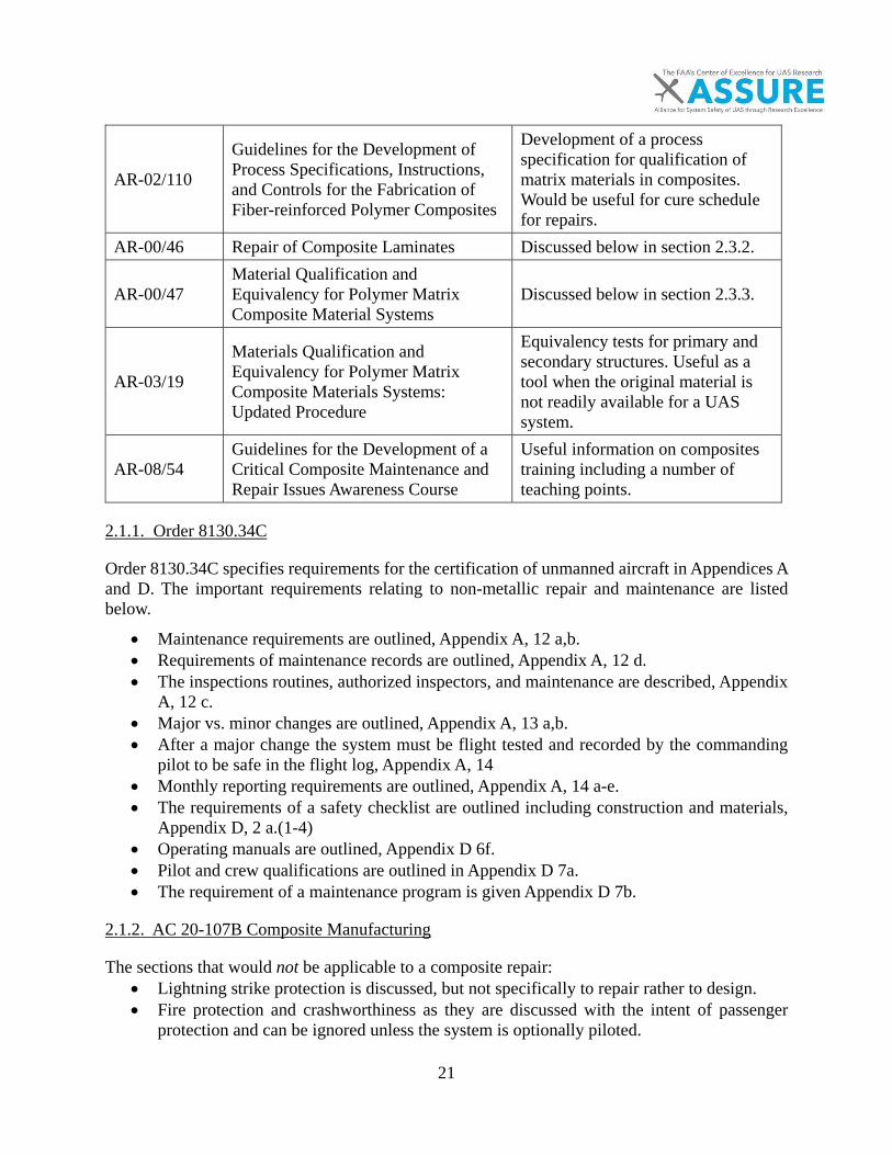
21
AR-02/110
Guidelines for the Development of Process Specifications, Instructions, and Controls for the Fabrication of Fiber-reinforced Polymer Composites
Development of a process specification for qualification of matrix materials in composites. Would be useful for cure schedule for repairs.
AR-00/46 Repair of Composite Laminates Discussed below in section 2.3.2.
AR-00/47 Material Qualification and Equivalency for Polymer Matrix Composite Material Systems
Discussed below in section 2.3.3.
AR-03/19
Materials Qualification and Equivalency for Polymer Matrix Composite Materials Systems: Updated Procedure
Equivalency tests for primary and secondary structures. Useful as a tool when the original material is not readily available for a UAS system.
AR-08/54 Guidelines for the Development of a Critical Composite Maintenance and Repair Issues Awareness Course
Useful information on composites training including a number of teaching points.
2.1.1. Order 8130.34C
Order 8130.34C specifies requirements for the certification of unmanned aircraft in Appendices A and D. The important requirements relating to non-metallic repair and maintenance are listed below.
• Maintenance requirements are outlined, Appendix A, 12 a,b. • Requirements of maintenance records are outlined, Appendix A, 12 d. • The inspections routines, authorized inspectors, and maintenance are described, Appendix
A, 12 c. • Major vs. minor changes are outlined, Appendix A, 13 a,b. • After a major change the system must be flight tested and recorded by the commanding
pilot to be safe in the flight log, Appendix A, 14 • Monthly reporting requirements are outlined, Appendix A, 14 a-e. • The requirements of a safety checklist are outlined including construction and materials,
Appendix D, 2 a.(1-4) • Operating manuals are outlined, Appendix D 6f. • Pilot and crew qualifications are outlined in Appendix D 7a. • The requirement of a maintenance program is given Appendix D 7b.
2.1.2. AC 20-107B Composite Manufacturing
The sections that would not be applicable to a composite repair: • Lightning strike protection is discussed, but not specifically to repair rather to design. • Fire protection and crashworthiness as they are discussed with the intent of passenger
protection and can be ignored unless the system is optionally piloted.

22
2.1.3. Appropriate 14 CRF Parts to the Repair and Maintenance of UAS
• 43.2, would improve the safety of UASs for non-metallic materials.• 43.3 covers the authorizations and would apply to the non-metallic specifically
composites for the repair and maintenance of composite materials.• 43.9 describes an acceptable method as described by Part 107 (sUAS) to record repairs.• 65.83 describes the airframe rating requirements and return to service requirements. An
airframe rating with a specialization in composite would be appropriate for completingand affecting repairs on composite materials based on the similarity to the thermoplasticmaterials.
• 65.83 (b) the discussion of the light sport aircraft gives a distinct example of the repairprocess for the rating applicability. This is a critical discussion point and describes aprocess for repair if the system is not type certified for the airframe repair. This woulddirectly apply to UAS systems.
• Part 135 could be applied to UAS structures specifically (a)(14) and part (c). This wouldrequire reporting if applied to major airframe damage of a UAS.
• Part 2X.603 and 2X.605 discusses the need for procure and process materials underapproved processes for composite repairs. This could also apply to thermoplasticmaterials.
• Part 2X.609 and 2X.613 discuss the need to prevent against service degradation.• Appendix G to Part 23 Instructions for Continued Airworthiness (a) describes the
requirements for a maintenance manual.
2.1.4. DOT/FAA/AR-00/446 Repair of Composite Laminates
The above document covers the differences in scarfed, lap, and stepped lap repair. Factors were assessed as to their influence on the tensile failure load of the repaired laminate. The roughness of the grinding tool, moisture content, test temperature, and curing temperature of the curing of the patch were studied as variables in the repair process. Models were developed for calculating the failure loads of the composite laminates. The patch used identical layup but different materials for the repairs. Test articles were cut from the repaired laminate. Scarf wet layup methods showed the best failure load at elevated temperature and humidity, while the use of pre-preg techniques showed the best return of strength under dry ambient conditions. (Pre-pregs are fiber-reinforced materials with resins impregnated in an uncured state.) The failure mode for the pre-preg scarf changed regions in the bulk laminate to failure at the repair between ambient and wet conditions. A scarf angle of between 0.75° and 1° from the baseline showed the lowest knockdown effect due to geometry. This is shown in Figure 11 from the AR00-46 report. The addition of overplies increased the strength of the repair with 2 overplies returning the greatest amount of strength. The study further indicated that if the moisture content of the system is below 1.0%, there is no effect on the strength of the repair. However, the area should be dried completely when the laminate moisture content is above 1.0%. Trends of moisture content to the repaired samples followed the general trends for non-damaged samples.
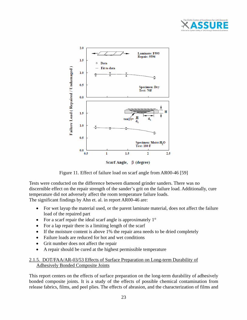
23
Figure 11. Effect of failure load on scarf angle from AR00-46 [59]
Tests were conducted on the difference between diamond grinder sanders. There was no discernible effect on the repair strength of the sander’s grit on the failure load. Additionally, cure temperature did not adversely affect the room temperature failure loads. The significant findings by Ahn et. al. in report AR00-46 are:
• For wet layup the material used, or the parent laminate material, does not affect the failure load of the repaired part
• For a scarf repair the ideal scarf angle is approximately 1° • For a lap repair there is a limiting length of the scarf • If the moisture content is above 1% the repair area needs to be dried completely • Failure loads are reduced for hot and wet conditions • Grit number does not affect the repair • A repair should be cured at the highest permissible temperature
2.1.5. DOT/FAA/AR-03/53 Effects of Surface Preparation on Long-term Durability of Adhesively Bonded Composite Joints
This report centers on the effects of surface preparation on the long-term durability of adhesively bonded composite joints. It is a study of the effects of possible chemical contamination from release fabrics, films, and peel plies. The effects of abrasion, and the characterization of films and
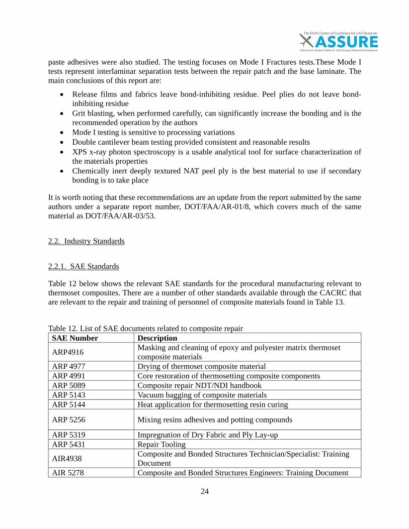
24
paste adhesives were also studied. The testing focuses on Mode I Fractures tests.These Mode I tests represent interlaminar separation tests between the repair patch and the base laminate. The main conclusions of this report are:
• Release films and fabrics leave bond-inhibiting residue. Peel plies do not leave bond-inhibiting residue
• Grit blasting, when performed carefully, can significantly increase the bonding and is the recommended operation by the authors
• Mode I testing is sensitive to processing variations • Double cantilever beam testing provided consistent and reasonable results • XPS x-ray photon spectroscopy is a usable analytical tool for surface characterization of
the materials properties • Chemically inert deeply textured NAT peel ply is the best material to use if secondary
bonding is to take place
It is worth noting that these recommendations are an update from the report submitted by the same authors under a separate report number, DOT/FAA/AR-01/8, which covers much of the same material as DOT/FAA/AR-03/53.
2.2. Industry Standards
2.2.1. SAE Standards
Table 12 below shows the relevant SAE standards for the procedural manufacturing relevant to thermoset composites. There are a number of other standards available through the CACRC that are relevant to the repair and training of personnel of composite materials found in Table 13. Table 12. List of SAE documents related to composite repair SAE Number Description
ARP4916 Masking and cleaning of epoxy and polyester matrix thermoset composite materials
ARP 4977 Drying of thermoset composite material ARP 4991 Core restoration of thermosetting composite components ARP 5089 Composite repair NDT/NDI handbook ARP 5143 Vacuum bagging of composite materials ARP 5144 Heat application for thermosetting resin curing
ARP 5256 Mixing resins adhesives and potting compounds
ARP 5319 Impregnation of Dry Fabric and Ply Lay-up ARP 5431 Repair Tooling
AIR4938 Composite and Bonded Structures Technician/Specialist: Training Document
AIR 5278 Composite and Bonded Structures Engineers: Training Document
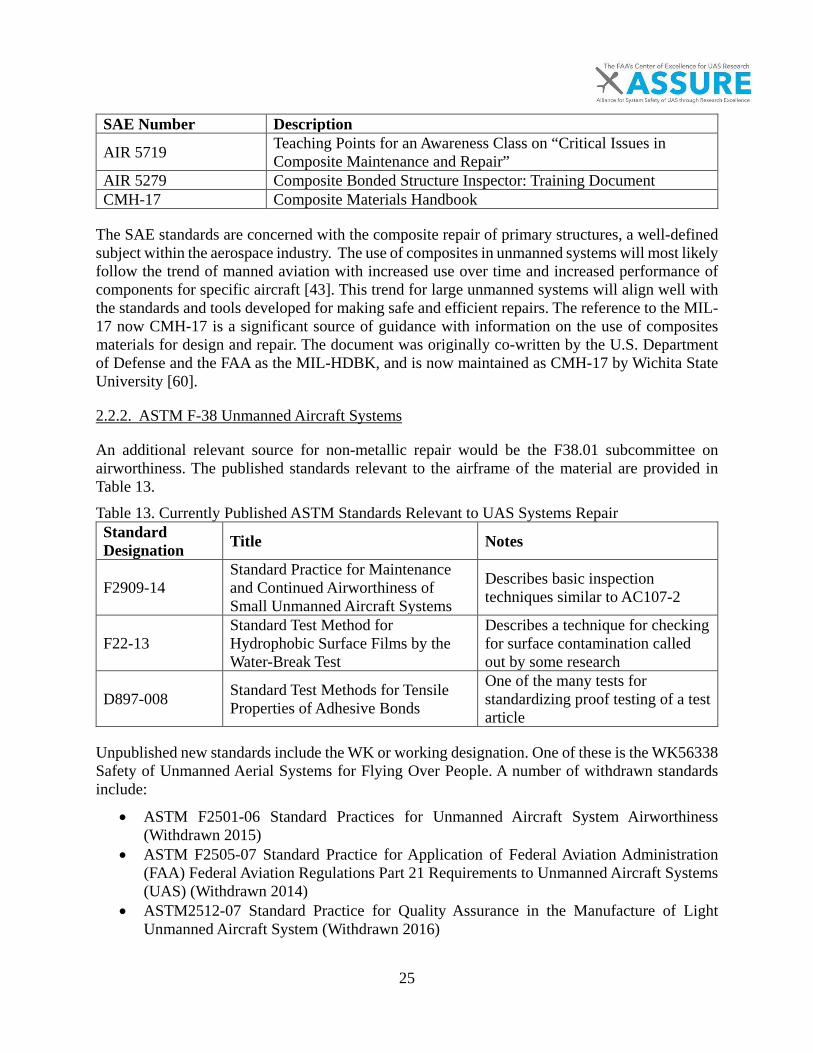
25
SAE Number Description
AIR 5719 Teaching Points for an Awareness Class on “Critical Issues in Composite Maintenance and Repair”
AIR 5279 Composite Bonded Structure Inspector: Training Document CMH-17 Composite Materials Handbook
The SAE standards are concerned with the composite repair of primary structures, a well-defined subject within the aerospace industry. The use of composites in unmanned systems will most likely follow the trend of manned aviation with increased use over time and increased performance of components for specific aircraft [43]. This trend for large unmanned systems will align well with the standards and tools developed for making safe and efficient repairs. The reference to the MIL-17 now CMH-17 is a significant source of guidance with information on the use of composites materials for design and repair. The document was originally co-written by the U.S. Department of Defense and the FAA as the MIL-HDBK, and is now maintained as CMH-17 by Wichita State University [60].
2.2.2. ASTM F-38 Unmanned Aircraft Systems
An additional relevant source for non-metallic repair would be the F38.01 subcommittee on airworthiness. The published standards relevant to the airframe of the material are provided in Table 13. Table 13. Currently Published ASTM Standards Relevant to UAS Systems Repair Standard Designation Title Notes
F2909-14 Standard Practice for Maintenance and Continued Airworthiness of Small Unmanned Aircraft Systems
Describes basic inspection techniques similar to AC107-2
F22-13 Standard Test Method for Hydrophobic Surface Films by the Water-Break Test
Describes a technique for checking for surface contamination called out by some research
D897-008 Standard Test Methods for Tensile Properties of Adhesive Bonds
One of the many tests for standardizing proof testing of a test article
Unpublished new standards include the WK or working designation. One of these is the WK56338 Safety of Unmanned Aerial Systems for Flying Over People. A number of withdrawn standards include:
• ASTM F2501-06 Standard Practices for Unmanned Aircraft System Airworthiness(Withdrawn 2015)
• ASTM F2505-07 Standard Practice for Application of Federal Aviation Administration(FAA) Federal Aviation Regulations Part 21 Requirements to Unmanned Aircraft Systems(UAS) (Withdrawn 2014)
• ASTM2512-07 Standard Practice for Quality Assurance in the Manufacture of LightUnmanned Aircraft System (Withdrawn 2016)
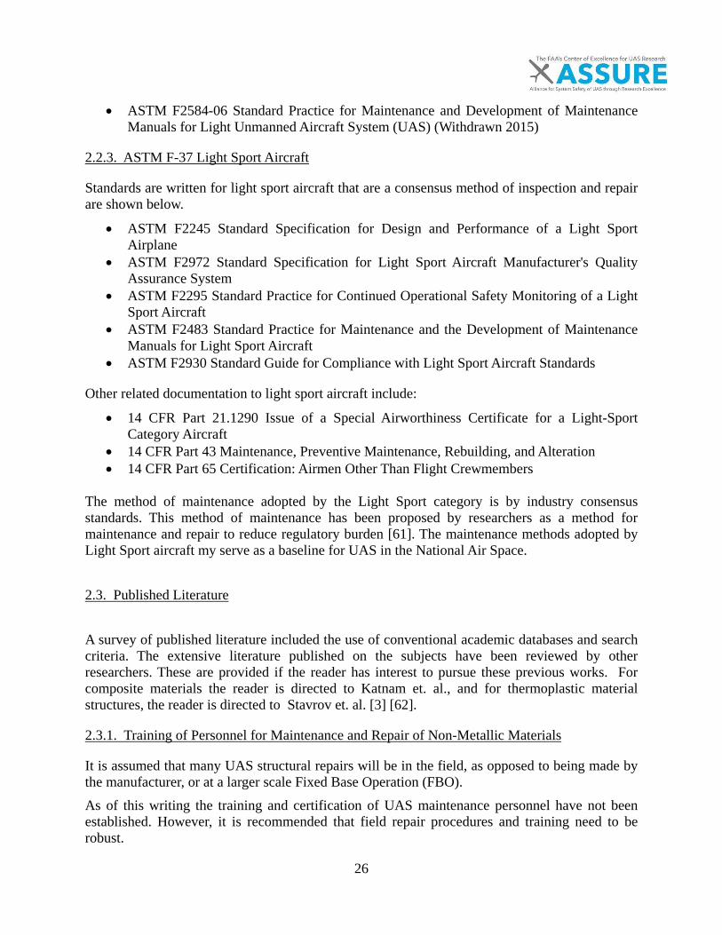
26
• ASTM F2584-06 Standard Practice for Maintenance and Development of Maintenance Manuals for Light Unmanned Aircraft System (UAS) (Withdrawn 2015)
2.2.3. ASTM F-37 Light Sport Aircraft
Standards are written for light sport aircraft that are a consensus method of inspection and repair are shown below.
• ASTM F2245 Standard Specification for Design and Performance of a Light Sport Airplane
• ASTM F2972 Standard Specification for Light Sport Aircraft Manufacturer's Quality Assurance System
• ASTM F2295 Standard Practice for Continued Operational Safety Monitoring of a Light Sport Aircraft
• ASTM F2483 Standard Practice for Maintenance and the Development of Maintenance Manuals for Light Sport Aircraft
• ASTM F2930 Standard Guide for Compliance with Light Sport Aircraft Standards
Other related documentation to light sport aircraft include:
• 14 CFR Part 21.1290 Issue of a Special Airworthiness Certificate for a Light-Sport Category Aircraft
• 14 CFR Part 43 Maintenance, Preventive Maintenance, Rebuilding, and Alteration • 14 CFR Part 65 Certification: Airmen Other Than Flight Crewmembers
The method of maintenance adopted by the Light Sport category is by industry consensus standards. This method of maintenance has been proposed by researchers as a method for maintenance and repair to reduce regulatory burden [61]. The maintenance methods adopted by Light Sport aircraft my serve as a baseline for UAS in the National Air Space.
2.3. Published Literature
A survey of published literature included the use of conventional academic databases and search criteria. The extensive literature published on the subjects have been reviewed by other researchers. These are provided if the reader has interest to pursue these previous works. For composite materials the reader is directed to Katnam et. al., and for thermoplastic material structures, the reader is directed to Stavrov et. al. [3] [62].
2.3.1. Training of Personnel for Maintenance and Repair of Non-Metallic Materials
It is assumed that many UAS structural repairs will be in the field, as opposed to being made by the manufacturer, or at a larger scale Fixed Base Operation (FBO). As of this writing the training and certification of UAS maintenance personnel have not been established. However, it is recommended that field repair procedures and training need to be robust.

27
For example, the points made by Welder discuss the need for a field repair to be low cost, limited in complex equipment, with a high level of reparability under non-controlled conditions [63]. This is achievable for thermoplastic materials; however, this is not readily achievable for thermoset materials unless the system is protected from the risk of environmental surface contamination. Temporary repairs can be performed on systems in the field, but should be fixed in the long term as discussed in AC 43.13-1B [64].
2.3.2. Repair of Composite Materials
The repair of non-metallic materials is well studied. The authors Baker, Hart-Smith, and Katnam are some of the respected authors in the field with a special issue on composite repair published by Composites A in 2009 [53, 54, 65, 66]. Katnam provides an extensive review of the process of repairing of composite materials including some of the challenges and the needs for effective repairs on composite materials [3]. In his paper, the need for a strong-fiber to matrix bond is discussed. Strong fiber to matrix adhesion is achieved through effective surface preparation. Length scales of composite damage are important for the development of “robust design rules”. In this context, length scale refers to damage scale from the micro level to macroscopic failure. This length scale alludes to the difference between micro-cracking which may allow seepage of hydraulic and other contaminating fluids to visual structural damage [3]. This is aligned with the damage tolerant design methodology of the FAA in which categories of damage are explicitly described depending on their severity and criticality. Representations of the damage categories from the FAA are shown in Figure 12.
Figure 12. Description of damage in AC20-107 [10]
Katnam’s paper categorizes composite repair into six steps. These categories include the damage assessment phase, material removal, surface preparation, patch fabrication, design, and monitoring

28
and automation. Each of these steps will have their own requirements based on the type of repair being performed [3]. A significant number of other researchers agree with the approaches as performed by the FAA and as recommended by the SAE. Both experimental testing and numerical models are studied by Campilho et. al. [67-69]. Damage in composite materials can come from a multitude of sources and will produce defects in the material that fall into three specific categories: delamination, matrix crack, and holes [70]. Damaged areas can be analyzed for their stress state by a number methods of varying complexity and have been reviewed by Paris for NASA [71]. Appropriate methods should be utilized for the analysis of the stress states if preliminary engineering data is unavailable or the SRM does not specifically cover a similar repair scenario. For the return of strength of a repair Ahn et. al. experimentally found that the failure load drops significantly for composites repaired with pre-preg in wet environments [59]. If a system is to be operating in a humid or hot environment (180°F) a wet lay-up technique is better suited for repair than replacing the system with pre-preg. This is hypothesized to be caused by a drop in the adhesive layers shear strength in pre-preg composite repairs [59]. Numerical models are compared by Odi et. al. in which there is an excellent review of the literature for composite repair methodologies [72]. The discussion of adhesively bonded structural repairs (ABSR) compared to mechanically fastened structural repairs (MFSR) is a topic of discussion by researchers [70]. The preference appears to trend towards adhesively bonded structural repairs (ABSR) under which scarf repairs fall as compared to mechanically fastened structural repairs (MFSR). MFSRs are still utilized for thick composites in which the shear strength of the adhesive cannot support the shear of the structure and may be hybridized with adhesives [73]. On an 8 layer parent laminate, a scarf repair will retain a ratio of between 0.5 and 1.0 of the original strength and operating conditions and the parent laminates matrix system [59]. A stepped patch repair will retain between 0.3 and 0.7 of the original strength dependent on the environmental factors [59]. For the bonding of composite materials Banea et. al. provide a review of the factors of bonding composite joints including sandwich structures [39]. These factors include the joint configuration: single lap, double lap, etc. and the types of adhesive: failure modes cohesive, adhesive, and structural (substrate). Typical adhesives are discussed with a service temperature range and a cure processes. Models for a suitable design of external patches are outlined by Gong and a stepped or scarf repair optimization was developed by Bendemra and Wang [74, 75]. A process for the certification of primary structures was developed for the FAA type certification framework by Baker et.al. [76].
2.3.3. Repair of Thermoplastic Materials
The most common technique utilized for the repair of thermoplastic materials is resistance welding, also known as fusion welding [40, 63, 77-79]. This method uses the flow-ability of thermoplastic matrixes above their glass transition temperature. This method was explored by Eveno, which concluded that homogeneous temperature distributions create greater reproducibility in thermoplastic composite repair techniques [80]. Fusion bonding may be classified by the way in which energy is applied to the material and is classified by Yousefpour [40]. These methods are

29
covered in Table 14. Additional resources on processing and joining are covered by independent studies and industry white papers [81, 82]. Table 14. Methods of Energy Application for Fusion Bonding [40] Method of energy application Example Limitations Thermal welding Hot tool welding Uneven heat distribution Friction Ultrasonic welding Penetration Electromagnetic Induction welding Cost
Additional best practices and methods of repair of to varying types of thermoplastic materials are documented by consumer websites [40]. The general practice for a repair of a non-reinforced crack of a homogeneous thermoplastic structure is to grind away the plastic with a rotary tool, clean the area to remove contamination, and replace the material with a thermoplastic heat gun. The influence of oxidization and the addition of reinforcements need to be considered. [83]. Because of the isotropic nature of thermoplastic materials, the repair of thermoplastic materials is trivial. The process of repairing a cracked thermoplastic material involves using a heated welding gun to add material to an area where the material has been removed [83]. The bonding of thermoplastic materials should be avoided; the chemically inert nature of thermoplastic materials makes the bonding through the use of thermosetting materials difficult. Mechanical fastening introduces stress concentrations that may lead to creep and failure. The predominant repair method is filling with a like material for low stress applications. Chapman et. al. studied the microscopic requirements of thermoplastic repair process--including the process history [84]. The effects of cooling rates are important for semi-crystalline materials, as the degree of crystallinity will influence the mechanical properties and solvent sensitivity. Adverse cooling effects also include the residual stresses from interior and exterior (skin/core) temperature gradients [84]. This microstructure and residual stresses eliminate the need for trial repairs on systems as needed beyond what was conducted within this paper. Substantiated repair schemes could be applied to materials of that type for future use. For high stress application of thermoplastic materials, the use of continuously reinforced thermoplastic tape is a relatively new commercial application [85]. These systems are repaired in a hybrid manner to a thermoplastic and thermoset material. For repair the application of the preferred scarf angle in most thermoset repairs is difficult because of the softness of most thermoplastics and the hardness of reinforcement material. Stavrov provides a review of the resistance welding of thermoplastic composites [62]. Fiber reinforced thermoplastic materials are distinctly different than unreinforced thermoplastic materials. Thermoplastic composites attempt to blend the properties of thermoplastic and thermoset materials properties by blending the strength and stiffness of thermosetting composites and the storage and impact strength of thermoplastic materials. The sacrifice made is in the increased processing difficulties of these materials [86]. Welder discussed the structural repair of thermoplastic composites nearly 20 years earlier and the viability of field repair with a clean surface. The study by Welder uses low weight reinforcement between 30% and 40% loadings [63].If a repair is to be performed on fiber reinforced thermoplastic materials type, validation tests should be conducted, such as the methods outlined by Reyes in which laminates were checked for specific damage against the undamaged composite [78].
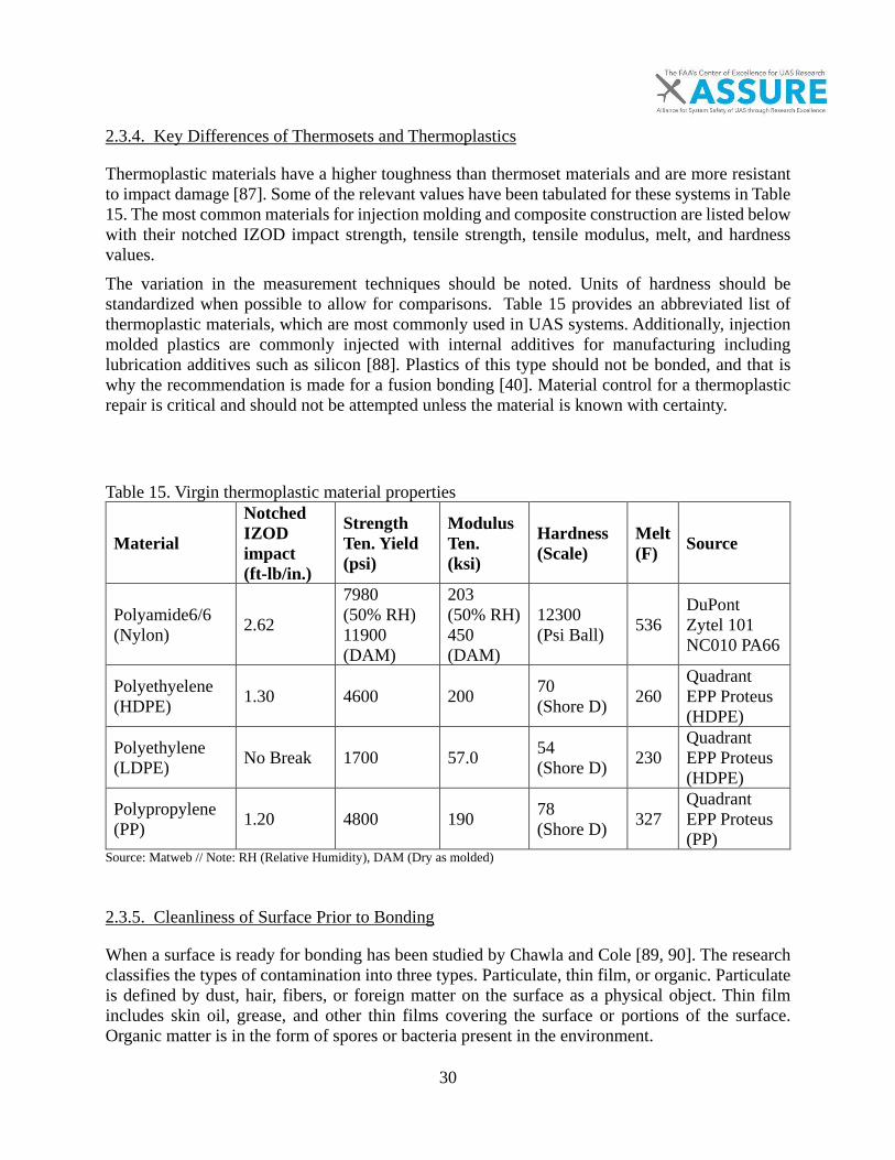
30
2.3.4. Key Differences of Thermosets and Thermoplastics
Thermoplastic materials have a higher toughness than thermoset materials and are more resistant to impact damage [87]. Some of the relevant values have been tabulated for these systems in Table 15. The most common materials for injection molding and composite construction are listed below with their notched IZOD impact strength, tensile strength, tensile modulus, melt, and hardness values. The variation in the measurement techniques should be noted. Units of hardness should be standardized when possible to allow for comparisons. Table 15 provides an abbreviated list of thermoplastic materials, which are most commonly used in UAS systems. Additionally, injection molded plastics are commonly injected with internal additives for manufacturing including lubrication additives such as silicon [88]. Plastics of this type should not be bonded, and that is why the recommendation is made for a fusion bonding [40]. Material control for a thermoplastic repair is critical and should not be attempted unless the material is known with certainty. Table 15. Virgin thermoplastic material properties
Material
Notched IZOD impact (ft-lb/in.)
Strength Ten. Yield (psi)
Modulus Ten. (ksi)
Hardness (Scale)
Melt (F) Source
Polyamide6/6 (Nylon) 2.62
7980 (50% RH) 11900 (DAM)
203 (50% RH) 450 (DAM)
12300 (Psi Ball) 536
DuPont Zytel 101 NC010 PA66
Polyethyelene (HDPE) 1.30 4600 200 70
(Shore D) 260 Quadrant EPP Proteus (HDPE)
Polyethylene (LDPE) No Break 1700 57.0 54
(Shore D) 230 Quadrant EPP Proteus (HDPE)
Polypropylene (PP) 1.20 4800 190 78
(Shore D) 327 Quadrant EPP Proteus (PP)
Source: Matweb // Note: RH (Relative Humidity), DAM (Dry as molded)
2.3.5. Cleanliness of Surface Prior to Bonding
When a surface is ready for bonding has been studied by Chawla and Cole [89, 90]. The research classifies the types of contamination into three types. Particulate, thin film, or organic. Particulate is defined by dust, hair, fibers, or foreign matter on the surface as a physical object. Thin film includes skin oil, grease, and other thin films covering the surface or portions of the surface. Organic matter is in the form of spores or bacteria present in the environment.
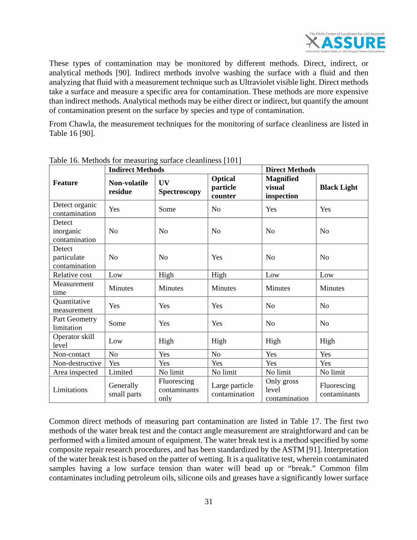
31
These types of contamination may be monitored by different methods. Direct, indirect, or analytical methods [90]. Indirect methods involve washing the surface with a fluid and then analyzing that fluid with a measurement technique such as Ultraviolet visible light. Direct methods take a surface and measure a specific area for contamination. These methods are more expensive than indirect methods. Analytical methods may be either direct or indirect, but quantify the amount of contamination present on the surface by species and type of contamination. From Chawla, the measurement techniques for the monitoring of surface cleanliness are listed in Table 16 [90]. Table 16. Methods for measuring surface cleanliness [101]
Feature
Indirect Methods Direct Methods
Non-volatile residue
UV Spectroscopy
Optical particle counter
Magnified visual inspection
Black Light
Detect organic contamination Yes Some No Yes Yes
Detect inorganic contamination
No No No No No
Detect particulate contamination
No No Yes No No
Relative cost Low High High Low Low Measurement time Minutes Minutes Minutes Minutes Minutes
Quantitative measurement Yes Yes Yes No No
Part Geometry limitation Some Yes Yes No No
Operator skill level Low High High High High
Non-contact No Yes No Yes Yes Non-destructive Yes Yes Yes Yes Yes Area inspected Limited No limit No limit No limit No limit
Limitations Generally small parts
Fluorescing contaminants only
Large particle contamination
Only gross level contamination
Fluorescing contaminants
Common direct methods of measuring part contamination are listed in Table 17. The first two methods of the water break test and the contact angle measurement are straightforward and can be performed with a limited amount of equipment. The water break test is a method specified by some composite repair research procedures, and has been standardized by the ASTM [91]. Interpretation of the water break test is based on the patter of wetting. It is a qualitative test, wherein contaminated samples having a low surface tension than water will bead up or “break.” Common film contaminates including petroleum oils, silicone oils and greases have a significantly lower surface

32
tension than water, so this test can be effective. If the water break test is utilized, deionized, pure water should be used to avoid contamination and the surface should be completely dried before continuing with the repair process. Optically Simulated Electronic Emission (OSEE) and Measurement of Evaporative Rate Analysis (MESERN) are complex analytical techniques, typically beyond the capabilities for field repair facilities or even FAA authorized repair stations. To check the surface contamination of systems, the water break test is commonly used for organic contamination, but is limited to organic contamination. For particulate matter, another common form of contamination, the surface should be wiped with a clean, lint free cloth after grinding until the newly exposed area of the cloth is clean and no longer picks up particulate matter. A controlled environment should be used in conditions for which particulate matter contamination is a concern. The surface should be covered prior to bonding with a non-reactive film prior to bonding. Placing readily available vacuum bagging material works well for protecting the surface from particulate matter. Table 17. Direct methods for measuring surface contamination [101]
Feature Water break test Contact angle OSEE MESERN
Total organic carbon (TOC)
Detect organic contamination Yes Yes Yes Yes Yes
Detect inorganic contamination
No No Yes No No
Detect particulate contamination
No No No No No
Relative cost Low Medium Medium Medium Medium Measurement time Minutes Minutes Seconds Minutes Minutes
Quantitative measurement No Yes Yes Yes Yes
Part geometry limitation Some Flat surface No Flat surface No
Operator skill level Low Medium Low Medium High
Non-contact No No Yes No Yes Non-destructive Yes Yes Yes Yes Yes
Area inspected No limit Small No limit Limited Limited
Limitations Hydrophobic contamination only
Hydrophobic contamination only
Materials must have a static charge
Requires radioactive fluid
High temperature environment
33
Common analytical methods for determining the surface contamination include the use of a number of devices, such as auger electron spectroscopy, energy dispersive spectroscopy, dynamic secondary ion mass spectroscopy and Fourier transform infrared spectroscopy. These techniques require a high degree of skill and would provide crucial information for the small portion of high risk repairs.
2.4. Current Practices for Repair of a UAS
The current methodology of unmanned systems can be bifurcated into two construction paradigms. The first construction paradigm is the use of consumer technologies to build a robust system for consumer use. The second paradigm is the adaptation of military technology [45]. Military UAS designs range from small consumer based technology fixed wing systems, the senseFLY SA eBee in Figure 3, to much larger system designs, the RQ-4 Global Hawk, Figure 8. The large system airframes are based on either military airworthiness specifications or commercial specifications [47]. These systems have extensive documentation and a SRM structural repair manual for continued airworthiness. Repair practices for the military systems will significantly differ from the consumer systems.
34
3. DAMAGE AND INSPECTION OF NON-METALLIC MATERIALS
Damage mechanisms will be different depending on the material and construction. The common construction methods for UASs will depend on the size of the system and the flight requirements of the system. Some methods include:
• Injection molded thermoplastic parts• Solid thermoset composite laminate• Sandwich thermoset composite laminates
The damage mechanisms for the non-metallic will depend on the energy of the impact and the shape of the impact. Whether the application of load is from a blunt impactor or a sharp impactor determines the mechanism of damage for composites. These effects have been well studied [92-96]. The damage effects of the sandwich panels was researched by the FAA [27]. Depending on whether the core material is honeycomb or foam, the damage mechanisms will be different [27]. Injection molded thermoplastic damage can be inspected by a number methods, but do not suffer from the complex anisotropic effects of damage found in composite materials [97]. The damage can be created by a number of mechanisms from harsh landings, hail impact, or any other event that would load a structure outside the mechanical design envelope of the UAS. In general, after any incident such as a fly away or link loss, a visual inspection will take place to check for damage to the system. However a number of additional methods for determining the extent of damage are described in previous work, ranging from simple visual methods to ultrasonic and acoustic techniques [98-100].
3.1. Determination of Extent of Damage
The characterization of the extent of damage is critical to performing a repair on a non-metallic system [99, 100]. Damage must be discovered if is it to be repaired. Finding and quantifying damage is a fundamental portion of the design and certification of manned aircraft, especially those designed to Damage Tolerant standards. Barely Visible Impact Damage (BVID) is often used as the lowest level damage which can reliability found. [17, 27, 101-103] . The distinction between visual damage and non-visual damage depends on a multitude of factors for non-metallic materials [104-106]. This distinction is managed by the failsafe and damage tolerant design criteria in manned aircraft [17]. The methods of inspection for non-metallics have been well studied and a comprehensive review into the formation of cracks and micro-cracks has been conducted by Awaja et. al. [100]. Hsu gives a complete overview of non-destructive inspection (NDI) techniques with relevant aerospace examples [107]. The most common techniques are ultrasonic inspection, and the lower cost options of tap testing and visual inspection are described below in brief. All of these inspection types find major use in the current manned paradigm and allow for characterization of the extent and location of damage. These analytical quantitative and qualitative techniques are usually seen as complimentary inspection techniques.

35
3.1.1. Ultrasonic Inspection
Ultrasonic inspections are well documented and relies on appropriate training [105, 108]. The major limitation of ultrasonic testing is the need for trial articles and the training required to be able to perform and interpret results. This type of non-destructive inspection is best suited to large UAS systems. The cost of the inspection will outweigh the cost of the replacement part on typical small UAS systems. Ultrasonic inspection is a topic of a significant amount of research and training exercises.
3.1.2. Tap Testing
The method of tap testing is when a person uses a small hammer to tap on the system and listen for an auditory change of the pitch difference in composite materials [107]. Tap testing, although a low cost and quick alternative to the more specific ultrasound techniques, requires the user to be able to hear the specific pitch difference between an area with and without delamination [109]. Furthermore, this technique is unable to identify small defects. This tap test works well for thermoset resin of high performance pre-preg and other continuous materials. It does not work well for thermoplastic materials to detect micro cracks or a heat affected zone. For any thermosetting material, tap testing should be the first mode of inspection to trace any potential damaged area before continuing further with other techniques. The instrumentation of the tap testing procedures has been utilized to perform a more quantifiable test [107].
3.1.3. Visual Inspection
Visual inspection is a useful technique for inspecting the exterior of structures [106]. This method should be performed before every flight on flight critical surfaces such as rotors and critical support structures of small, unmanned systems. This recommendation aligns with the general inspection requirement for Part 107 flight. The methods of visual inspection will differ depending on the system, but with small systems, access to inspection points will not be an issue. The methods of visual inspection are covered by published FAA documentation and researchers [106, 110].
3.1.4. Additional Damage Inspection Types
Additional methods have been developed for the inspection of non-metallic materials and range from thermal inspection to digital image correlation under proof loads. These methods could be utilized, but are not as common as ultrasonic, visual, and tap testing [107].
3.2. General Preflight Inspection
Preflight inspection will depend on the size of the system. Smaller systems will be able to be inspected more regularly than larger systems. The Part 107 inspection procedure as it relates to non-metallic materials requires a visual inspection before every operation [34]. This inspection procedure also discusses the need to inspect the rotors for potential imbalance issues that may lead to unsafe flight.
36
The manufacturer recommended procedures of sUAS include checking the airframe visually for cracks and checking the rotation of the rotors on multi-rotor craft. This includes powering on the rotors and checking for imbalance visually [111]. For fixed wing systems, flight surfaces and control surfaces should be checked. Larger unmanned aircraft would follow the checklist for structural defects and visual damage as a normal type-certified aircraft.
3.2.1. Disposition after Inspection
The disposition after inspection would be dependent on the damage. If the rotors were damaged these rotors should be replaced for small systems. Rotors are inexpensive to the point that the cost of a repair will far outweigh the cost of developing a repair procedure, or simply by replacing the part. Flights should be grounded until approved manufacturer blades are supplied for any multi-rotor within the small UAS category. For fixed wing and larger aircraft, the repairs should conform to the structural repair manual (SRM). If there is no SRM, the structure should follow the major or minor repair designation. Any repair to a composite critical flight structure on the larger class systems should meet similar requirements to manned aviation. The construction methods are similar for these unmanned systems to manned aviation. This repair may include the need to include lightning strike protection systems and other functional items into the repair [112].
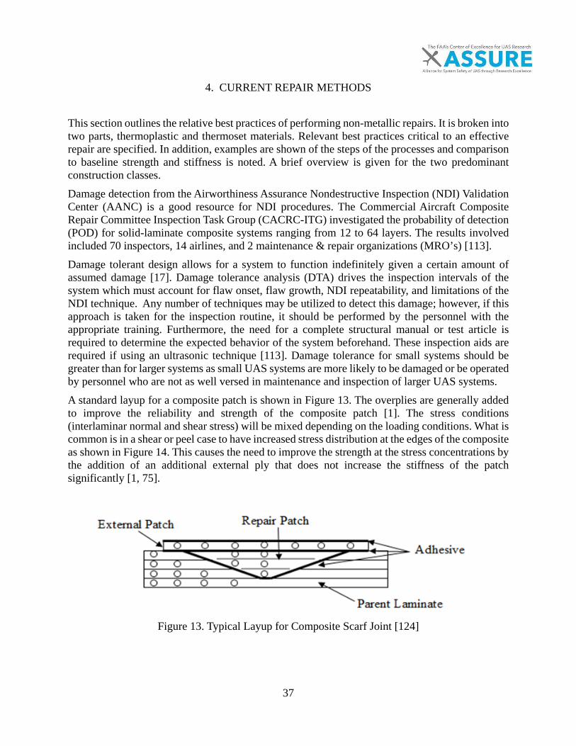
37
4. CURRENT REPAIR METHODS
This section outlines the relative best practices of performing non-metallic repairs. It is broken into two parts, thermoplastic and thermoset materials. Relevant best practices critical to an effective repair are specified. In addition, examples are shown of the steps of the processes and comparison to baseline strength and stiffness is noted. A brief overview is given for the two predominant construction classes. Damage detection from the Airworthiness Assurance Nondestructive Inspection (NDI) Validation Center (AANC) is a good resource for NDI procedures. The Commercial Aircraft Composite Repair Committee Inspection Task Group (CACRC-ITG) investigated the probability of detection (POD) for solid-laminate composite systems ranging from 12 to 64 layers. The results involved included 70 inspectors, 14 airlines, and 2 maintenance & repair organizations (MRO’s) [113]. Damage tolerant design allows for a system to function indefinitely given a certain amount of assumed damage [17]. Damage tolerance analysis (DTA) drives the inspection intervals of the system which must account for flaw onset, flaw growth, NDI repeatability, and limitations of the NDI technique. Any number of techniques may be utilized to detect this damage; however, if this approach is taken for the inspection routine, it should be performed by the personnel with the appropriate training. Furthermore, the need for a complete structural manual or test article is required to determine the expected behavior of the system beforehand. These inspection aids are required if using an ultrasonic technique [113]. Damage tolerance for small systems should be greater than for larger systems as small UAS systems are more likely to be damaged or be operated by personnel who are not as well versed in maintenance and inspection of larger UAS systems. A standard layup for a composite patch is shown in Figure 13. The overplies are generally added to improve the reliability and strength of the composite patch [1]. The stress conditions (interlaminar normal and shear stress) will be mixed depending on the loading conditions. What is common is in a shear or peel case to have increased stress distribution at the edges of the composite as shown in Figure 14. This causes the need to improve the strength at the stress concentrations by the addition of an additional external ply that does not increase the stiffness of the patch significantly [1, 75].
Figure 13. Typical Layup for Composite Scarf Joint [124]
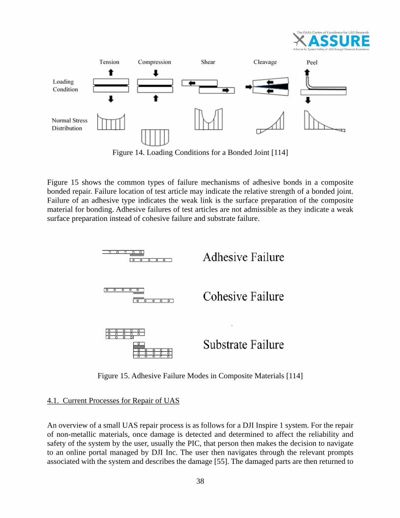
38
Figure 14. Loading Conditions for a Bonded Joint [114]
Figure 15 shows the common types of failure mechanisms of adhesive bonds in a composite bonded repair. Failure location of test article may indicate the relative strength of a bonded joint. Failure of an adhesive type indicates the weak link is the surface preparation of the composite material for bonding. Adhesive failures of test articles are not admissible as they indicate a weak surface preparation instead of cohesive failure and substrate failure.
Figure 15. Adhesive Failure Modes in Composite Materials [114]
4.1. Current Processes for Repair of UAS
An overview of a small UAS repair process is as follows for a DJI Inspire 1 system. For the repair of non-metallic materials, once damage is detected and determined to affect the reliability and safety of the system by the user, usually the PIC, that person then makes the decision to navigate to an online portal managed by DJI Inc. The user then navigates through the relevant prompts associated with the system and describes the damage [55]. The damaged parts are then returned to
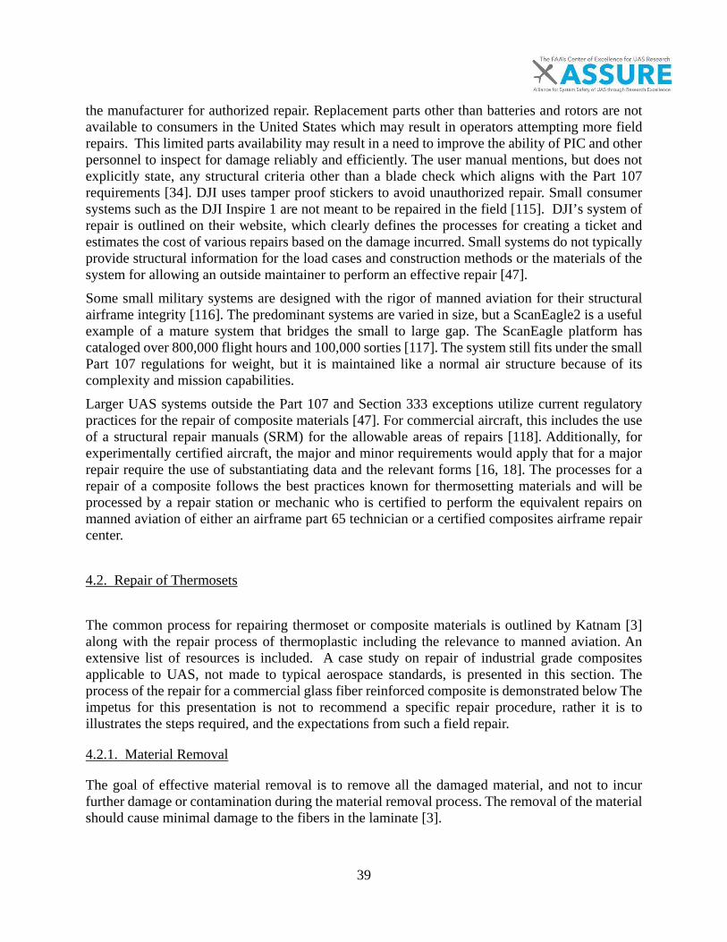
39
the manufacturer for authorized repair. Replacement parts other than batteries and rotors are not available to consumers in the United States which may result in operators attempting more field repairs. This limited parts availability may result in a need to improve the ability of PIC and other personnel to inspect for damage reliably and efficiently. The user manual mentions, but does not explicitly state, any structural criteria other than a blade check which aligns with the Part 107 requirements [34]. DJI uses tamper proof stickers to avoid unauthorized repair. Small consumer systems such as the DJI Inspire 1 are not meant to be repaired in the field [115]. DJI’s system of repair is outlined on their website, which clearly defines the processes for creating a ticket and estimates the cost of various repairs based on the damage incurred. Small systems do not typically provide structural information for the load cases and construction methods or the materials of the system for allowing an outside maintainer to perform an effective repair [47]. Some small military systems are designed with the rigor of manned aviation for their structural airframe integrity [116]. The predominant systems are varied in size, but a ScanEagle2 is a useful example of a mature system that bridges the small to large gap. The ScanEagle platform has cataloged over 800,000 flight hours and 100,000 sorties [117]. The system still fits under the small Part 107 regulations for weight, but it is maintained like a normal air structure because of its complexity and mission capabilities. Larger UAS systems outside the Part 107 and Section 333 exceptions utilize current regulatory practices for the repair of composite materials [47]. For commercial aircraft, this includes the use of a structural repair manuals (SRM) for the allowable areas of repairs [118]. Additionally, for experimentally certified aircraft, the major and minor requirements would apply that for a major repair require the use of substantiating data and the relevant forms [16, 18]. The processes for a repair of a composite follows the best practices known for thermosetting materials and will be processed by a repair station or mechanic who is certified to perform the equivalent repairs on manned aviation of either an airframe part 65 technician or a certified composites airframe repair center.
4.2. Repair of Thermosets
The common process for repairing thermoset or composite materials is outlined by Katnam [3] along with the repair process of thermoplastic including the relevance to manned aviation. An extensive list of resources is included. A case study on repair of industrial grade composites applicable to UAS, not made to typical aerospace standards, is presented in this section. The process of the repair for a commercial glass fiber reinforced composite is demonstrated below The impetus for this presentation is not to recommend a specific repair procedure, rather it is to illustrates the steps required, and the expectations from such a field repair.
4.2.1. Material Removal
The goal of effective material removal is to remove all the damaged material, and not to incur further damage or contamination during the material removal process. The removal of the material should cause minimal damage to the fibers in the laminate [3].

40
Removing paint is usually one of the first steps after damage has been observed and the decision has been made to make a repair rather than replace the part. A sodium bicarbonate or starch media is ideal for paint removal [119]. There should be a maximum amount of reuses set for any air delivered blasting media as approved by the SRM and trial testing. That is, the blast media should have a finite life such that it does not introduce contaminants from previous cycles. Plastic media may be used as well, sand and aluminum should be avoided as their material removal rate is too aggressive and will likely damage fibers. A flat nozzle with a fan shaped fan path avoids the hot spots of a cone nozzle and should be used for paint removal on composite structures [119]. These techniques apply to thermosetting materials as thermoplastics are usually pigmented or dyed. Once the paint is removed, the part may be further inspected through NDI for damage. Once the area has been marked, material removal may proceed. The use of diamond disks for grinding is recommended. Final surface preparation should be achieved with Scotch-Brite pads or a similar secondary treatment to avoid material contamination from anti-clogging additives found in some grinding materials. A 2” – 5” pneumatic right angle dual action (DA) sander is the recommended tool for removing material carefully. It offers the greatest control over other systems and may include a dust removal attachment powered by vacuum or other system. To remove material quickly, a handheld min-belt sander is preferred. It does not have the same amount of control as a DA sander, but removes material faster. Pneumatic systems should supply clean, dry air using a moisture trap or other system. Dust should be minimized. The use of wet grinding techniques is not recommended, as moisture contamination will adversely affect the bond. Contamination of carbon dust should be controlled as it will adversely affect electronic circuit reliability [120]. The materials utilized in repairs should be as close as possible to the original, and if the material is unknown, the reliability of the repair could be compromised. A structural repair manual will specify suitable materials for repair and must be references whenever available. In Figure 16, a fiberglass epoxy system material is removed for surface preparation of localized damage. The material system consists of Vectorply ElT-3800 Fabric and Hexion RIMR/RIMH 135 epoxy 100:33 parts by weight infused with a layup of [0/90/90/0] and a nominal thickness of 0.1181in (3mm). Other commonly available hand tools are shown for their grinding ability of a surface in Figure 17 and Figure 18. For rapid material removal of a fiberglass material, a rotary flap wheel tool or a hand belt sander is recommended.
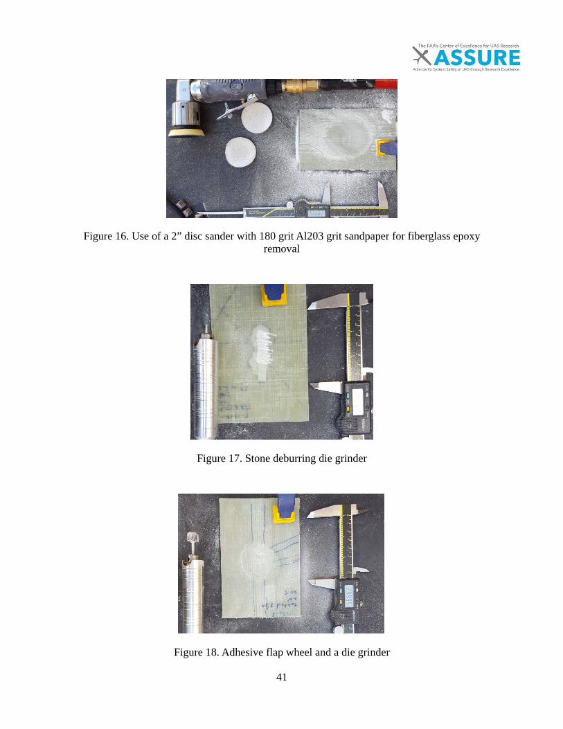
41
Figure 16. Use of a 2” disc sander with 180 grit Al203 grit sandpaper for fiberglass epoxy removal
Figure 17. Stone deburring die grinder
Figure 18. Adhesive flap wheel and a die grinder
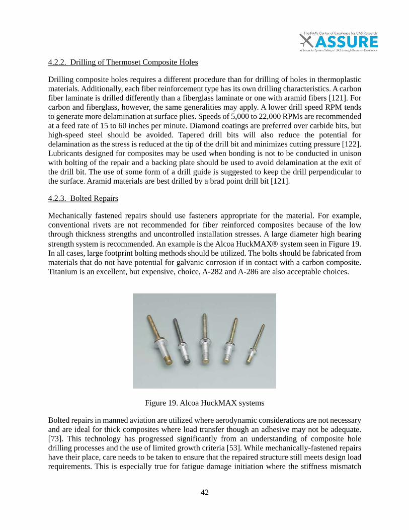
42
4.2.2. Drilling of Thermoset Composite Holes
Drilling composite holes requires a different procedure than for drilling of holes in thermoplastic materials. Additionally, each fiber reinforcement type has its own drilling characteristics. A carbon fiber laminate is drilled differently than a fiberglass laminate or one with aramid fibers [121]. For carbon and fiberglass, however, the same generalities may apply. A lower drill speed RPM tends to generate more delamination at surface plies. Speeds of 5,000 to 22,000 RPMs are recommended at a feed rate of 15 to 60 inches per minute. Diamond coatings are preferred over carbide bits, but high-speed steel should be avoided. Tapered drill bits will also reduce the potential for delamination as the stress is reduced at the tip of the drill bit and minimizes cutting pressure [122]. Lubricants designed for composites may be used when bonding is not to be conducted in unison with bolting of the repair and a backing plate should be used to avoid delamination at the exit of the drill bit. The use of some form of a drill guide is suggested to keep the drill perpendicular to the surface. Aramid materials are best drilled by a brad point drill bit [121].
4.2.3. Bolted Repairs
Mechanically fastened repairs should use fasteners appropriate for the material. For example, conventional rivets are not recommended for fiber reinforced composites because of the low through thickness strengths and uncontrolled installation stresses. A large diameter high bearing strength system is recommended. An example is the Alcoa HuckMAX system seen in Figure 19. In all cases, large footprint bolting methods should be utilized. The bolts should be fabricated from materials that do not have potential for galvanic corrosion if in contact with a carbon composite. Titanium is an excellent, but expensive, choice, A-282 and A-286 are also acceptable choices.
Figure 19. Alcoa HuckMAX systems
Bolted repairs in manned aviation are utilized where aerodynamic considerations are not necessary and are ideal for thick composites where load transfer though an adhesive may not be adequate. [73]. This technology has progressed significantly from an understanding of composite hole drilling processes and the use of limited growth criteria [53]. While mechanically-fastened repairs have their place, care needs to be taken to ensure that the repaired structure still meets design load requirements. This is especially true for fatigue damage initiation where the stiffness mismatch
43
and fastener configurations can lead to premature fatigue failure compared to the original structure and certification.
4.2.4. Preparation for Bonding
The use of solvents should be minimized and appropriate environmental, health, and safety (EHS) standards should be observed. Typical non-polar, commercial grade solvents are acceptable, however due to an unknown contaminant factor, reagent grade of high purity should be utilized to reduce the potential for contamination in the final cleaning steps. Lint-free cloths should be used to avoid further contamination of the surface [148].
4.2.5. Filler Material Repairs
Filler material repairs should only be used for repair of minor damage. A filler material is added to the surface and covered with a cloth to protect the interior from moisture. It serves a purpose of protecting the system from incurring moisture damage until a final structural repair may be performed on the system. It is useful as a field repair tool for minor damage to prevent delamination from moisture and undesired aerodynamics during flight [123].
4.2.6. Composite Layup and Orientation
Composite orientation is the foundation of composite materials as it allows for the placement of strength and stiffness in the primary loading direction. If not recreated during a repair the structure is severely compromised. If there is no known schedule of the composite layup it may be determined through a number of methods [124]. This is more effective for thin composites than thick composites. The interactions of matrix on the strength repair are also important and without this information, an effective repair to maximum strength is unlikely. However, manufacturers will generally provide this in structural repair manual documentation. The methods that exist for the determining the layup are either optical or by burn off methods [130]. The optical method takes training and can be limited to systems that are think laminates. The burn off method works exceptionally well for fiberglass materials. A fiberglass sample is placed in a heated furnace and the thermosetting material is allowed to oxidize. This method may also be used to determine fiber volume fraction of the system based on the weight before and after the burn off [125]. With sufficient grinding of a high aspect ratio scarf angle, the relative angles may be determined for a composite layup. This may be accomplished under an optical microscope and can be recorded for each specific part. This is a time consuming process and is judgment based [5, 126]. Training should include the effects of a layup of a composite material and its effect on the stiffness of the overall system. If there is any doubt on the layup the repair should not performed. When a structural repair manual is available, it should be utilized. Additionally, any extra layers should be in the primary direction of the top layer to avoid effects of stiffness mismatch leading to a scenario that would reduce the overall strength of the repair [132]. In bonding, it should be understood that the need for a clean surface is a necessity for all materials. There should be an understanding between the use of reagent grade and commercial or industrial grade solvents for cleaning. A test of surface cleanliness can be done with a wipe test for the

44
material or a beading test. The thin film criteria in that no bead should form is a good indication of a surface that is good for bonding [91].
4.2.7. Application of Vacuum
Vacuum compaction is a very import procedure for ensuring a good bond between the repair patch and the parent laminate. This is especially true for field repairs without an autoclave for laminate consolidation. Vacuum compaction is the easiest way to consolidate repairs, especially on curved surfaces. Recommended procedures include:
• For each square yard being vacuumed, a port should be added. • Vacuum should be measured away from the vacuum port to ensure the readings are
representative of what is being applied to the laminate. • If a vacuum is being applied for compaction, the layup should include a layer of peel ply,
a bleeder film, a separation film, and a breather film in which the bleeder and breather film connect at the edge of the part.
• The peel ply selection should consider the effects of the selection of these materials with respect to the final surface.
• The breather film should avoid saturation of the breather film to ensure uniform compaction.
Common materials for the bleeder layer(s) include 120 or 1581 fiberglass. Generally, a heavier layer of fiberglass fabric for the breather layer, such as a woven roving is desirable. The film used to separate the bleeder and breather may be a perforated as long as the layers of the bleeder are sufficient to absorb the excess resin. General vacuum supplies and tape should be appropriate to the temperature regime [162]. Additional requirements include:
• The tooling or part must not be porous • Leaks must be reduced to a specific range over a time period • The vacuum must be sized to accommodate the volume of bagged area • The breather must be continuous • The breather must not fill with resin • The breather and bleeder must contact at the edges.
4.3. Repair of Thermoplastics
The process of repairing a thermoplastic material is seen in Figure 20. Thermoplastic materials tend to haze and crack when exposed to damage. The removal of a thermoplastic material can be performed by a reciprocating air saw or jigsaw. This is specifically for unfilled composite materials or ones with relatively short glass fibers. The use of grinding discs would heat the structure, affecting the overall performance of the structure and will cause clogging issues [127]. The replacement of thermoplastic material is often called thermoplastic welding as the process is similar to that of welding metals. The equipment is specialized and comes in different forms [128].
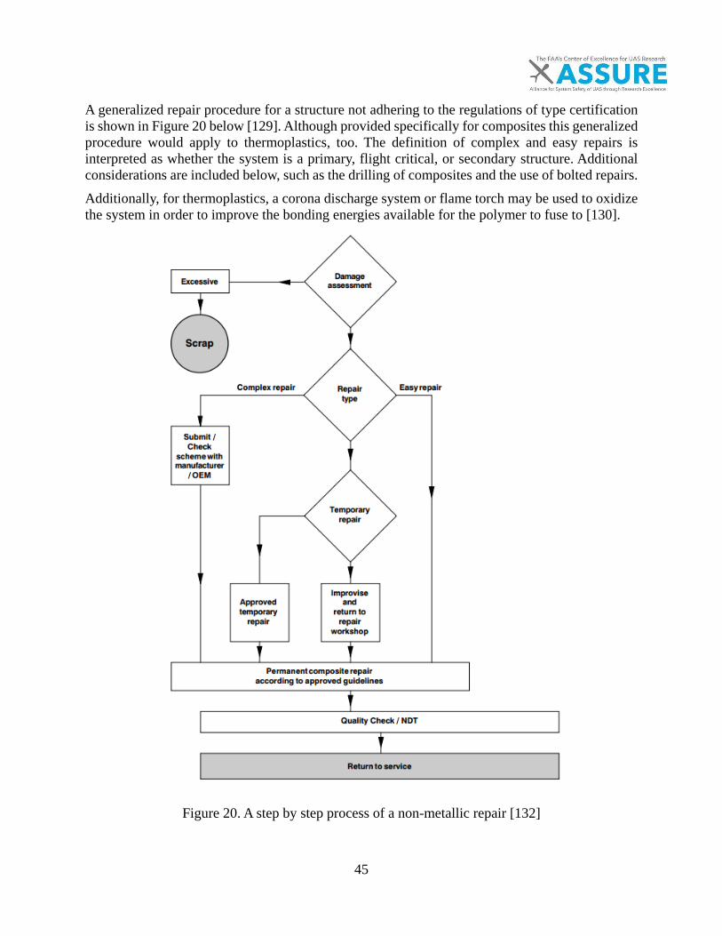
45
A generalized repair procedure for a structure not adhering to the regulations of type certification is shown in Figure 20 below [129]. Although provided specifically for composites this generalized procedure would apply to thermoplastics, too. The definition of complex and easy repairs is interpreted as whether the system is a primary, flight critical, or secondary structure. Additional considerations are included below, such as the drilling of composites and the use of bolted repairs. Additionally, for thermoplastics, a corona discharge system or flame torch may be used to oxidize the system in order to improve the bonding energies available for the polymer to fuse to [130].
Figure 20. A step by step process of a non-metallic repair [132]

46
4.3.1. Specialized Equipment for Non-Metallic Repair
Equipment for the repair of thermoplastic material is specialized to create consistent heating and reduce the surface oxidization of the material; the technology is a carry-over from the automotive industry. There are various suppliers and manufacturers for plastic repair equipment. The simplest system, without a nitrogen purge to avoid oxidization of some plastics, is shown in Figure 21 and essentially consists of a temperature controlled resistive heating element.
Figure 21. Polyvance fusion welding system
Additional equipment includes drying ovens and or heat lamps to reduce the moisture in the system. The typical moisture level retained in polyamide (Nylon) material is ~6% [127]. This amount of moisture will affect the bonding of the system, so steps should be taken to measure and control the moisture methods for composites which can be adapted for thermoplastic materials [131]. A key list of factors that that affect the strength of a thermoplastic repair include surface cleanliness, moisture, and the effects of polymer type on the overall bonding strength of a thermoplastic material. The five most common types of thermoplastics used in small, unmanned aircraft are, Polyamide 6/6 (Nylon 6/6), acrylonitrile butadiene styrene (ABS), polyethylene (PE), polypropylene (PP), and polyvinyl chloride (PVC). These materials require different temperatures during their processing and repair procedures. A range of temperatures for these systems is shown in Table 18 below. A technician should understand the effects of temperature on thermoplastics and could be taught a simple evaluation technique for the type of plastic based on exposing a piece to an open flame. Such a flame test should be conducted with the appropriate personal protective equipment such as a fume hood, a volatile organic compounds respirator, and sufficient airflow. A propane torch is recommended for the burning and melting of plastics. This is a destructive test and a sample should be pulled from the damaged unmanned system that is to be repaired. Thermosets may also be determined in this manner, but a structural repair manual should be consulted for
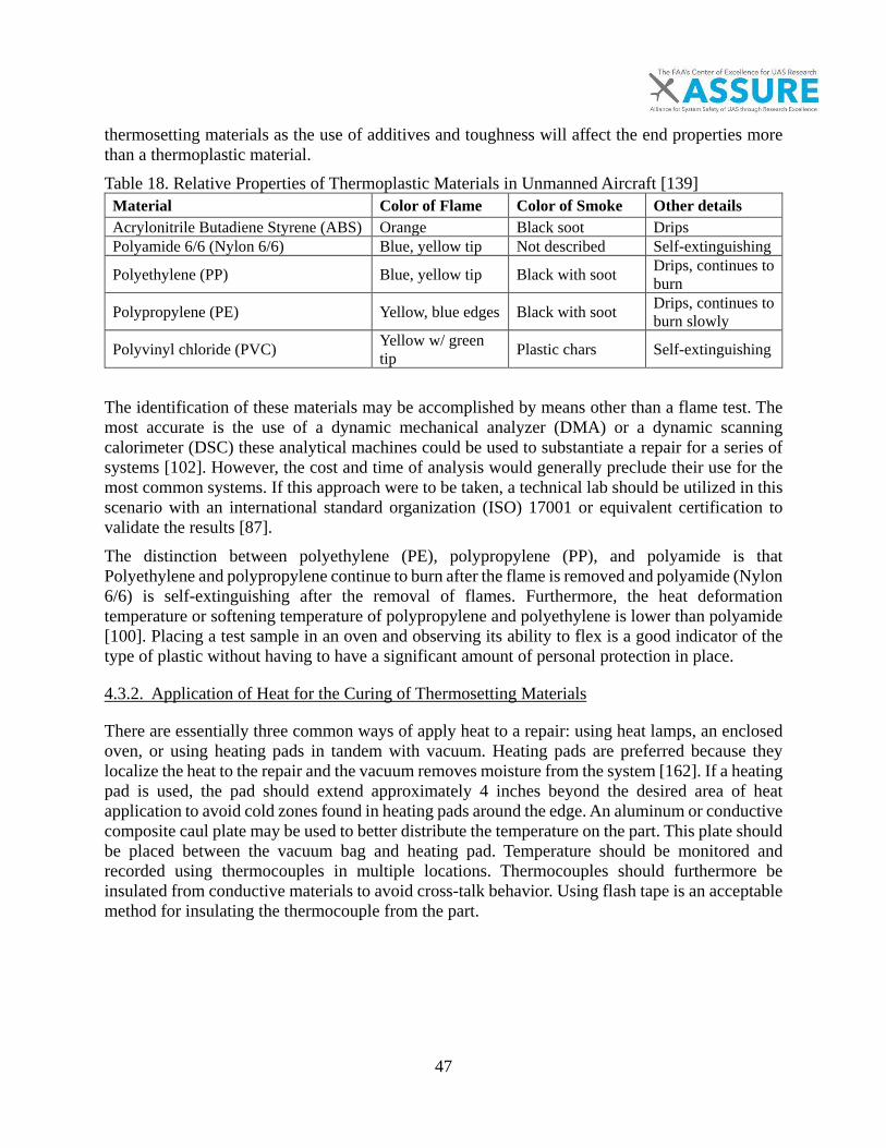
47
thermosetting materials as the use of additives and toughness will affect the end properties more than a thermoplastic material. Table 18. Relative Properties of Thermoplastic Materials in Unmanned Aircraft [139]
Material Color of Flame Color of Smoke Other details Acrylonitrile Butadiene Styrene (ABS) Orange Black soot Drips Polyamide 6/6 (Nylon 6/6) Blue, yellow tip Not described Self-extinguishing
Polyethylene (PP) Blue, yellow tip Black with soot Drips, continues to burn
Polypropylene (PE) Yellow, blue edges Black with soot Drips, continues to burn slowly
Polyvinyl chloride (PVC) Yellow w/ green tip Plastic chars Self-extinguishing
The identification of these materials may be accomplished by means other than a flame test. The most accurate is the use of a dynamic mechanical analyzer (DMA) or a dynamic scanning calorimeter (DSC) these analytical machines could be used to substantiate a repair for a series of systems [102]. However, the cost and time of analysis would generally preclude their use for the most common systems. If this approach were to be taken, a technical lab should be utilized in this scenario with an international standard organization (ISO) 17001 or equivalent certification to validate the results [87]. The distinction between polyethylene (PE), polypropylene (PP), and polyamide is that Polyethylene and polypropylene continue to burn after the flame is removed and polyamide (Nylon 6/6) is self-extinguishing after the removal of flames. Furthermore, the heat deformation temperature or softening temperature of polypropylene and polyethylene is lower than polyamide [100]. Placing a test sample in an oven and observing its ability to flex is a good indicator of the type of plastic without having to have a significant amount of personal protection in place.
4.3.2. Application of Heat for the Curing of Thermosetting Materials
There are essentially three common ways of apply heat to a repair: using heat lamps, an enclosed oven, or using heating pads in tandem with vacuum. Heating pads are preferred because they localize the heat to the repair and the vacuum removes moisture from the system [162]. If a heating pad is used, the pad should extend approximately 4 inches beyond the desired area of heat application to avoid cold zones found in heating pads around the edge. An aluminum or conductive composite caul plate may be used to better distribute the temperature on the part. This plate should be placed between the vacuum bag and heating pad. Temperature should be monitored and recorded using thermocouples in multiple locations. Thermocouples should furthermore be insulated from conductive materials to avoid cross-talk behavior. Using flash tape is an acceptable method for insulating the thermocouple from the part.
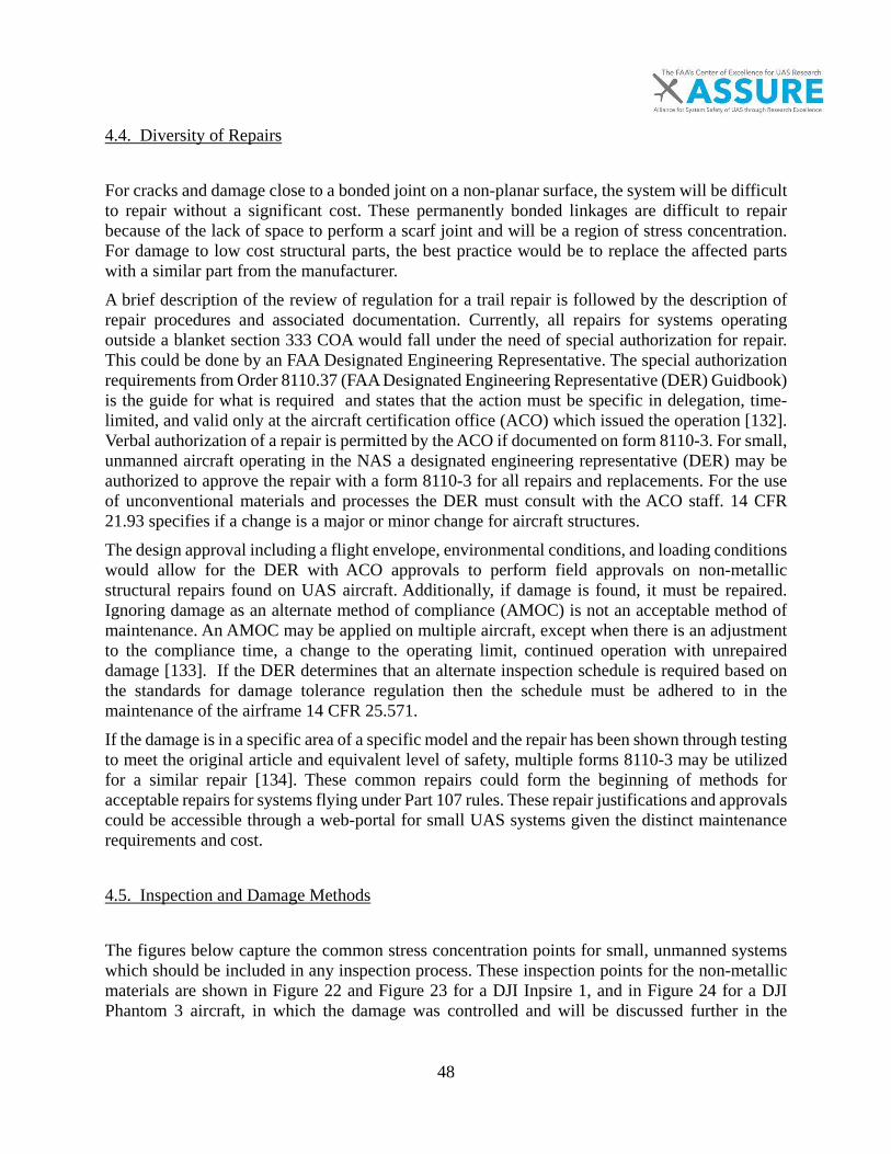
48
4.4. Diversity of Repairs
For cracks and damage close to a bonded joint on a non-planar surface, the system will be difficult to repair without a significant cost. These permanently bonded linkages are difficult to repair because of the lack of space to perform a scarf joint and will be a region of stress concentration. For damage to low cost structural parts, the best practice would be to replace the affected parts with a similar part from the manufacturer. A brief description of the review of regulation for a trail repair is followed by the description of repair procedures and associated documentation. Currently, all repairs for systems operating outside a blanket section 333 COA would fall under the need of special authorization for repair. This could be done by an FAA Designated Engineering Representative. The special authorization requirements from Order 8110.37 (FAA Designated Engineering Representative (DER) Guidbook) is the guide for what is required and states that the action must be specific in delegation, time-limited, and valid only at the aircraft certification office (ACO) which issued the operation [132]. Verbal authorization of a repair is permitted by the ACO if documented on form 8110-3. For small, unmanned aircraft operating in the NAS a designated engineering representative (DER) may be authorized to approve the repair with a form 8110-3 for all repairs and replacements. For the use of unconventional materials and processes the DER must consult with the ACO staff. 14 CFR 21.93 specifies if a change is a major or minor change for aircraft structures. The design approval including a flight envelope, environmental conditions, and loading conditions would allow for the DER with ACO approvals to perform field approvals on non-metallic structural repairs found on UAS aircraft. Additionally, if damage is found, it must be repaired. Ignoring damage as an alternate method of compliance (AMOC) is not an acceptable method of maintenance. An AMOC may be applied on multiple aircraft, except when there is an adjustment to the compliance time, a change to the operating limit, continued operation with unrepaired damage [133]. If the DER determines that an alternate inspection schedule is required based on the standards for damage tolerance regulation then the schedule must be adhered to in the maintenance of the airframe 14 CFR 25.571. If the damage is in a specific area of a specific model and the repair has been shown through testing to meet the original article and equivalent level of safety, multiple forms 8110-3 may be utilized for a similar repair [134]. These common repairs could form the beginning of methods for acceptable repairs for systems flying under Part 107 rules. These repair justifications and approvals could be accessible through a web-portal for small UAS systems given the distinct maintenance requirements and cost.
4.5. Inspection and Damage Methods
The figures below capture the common stress concentration points for small, unmanned systems which should be included in any inspection process. These inspection points for the non-metallic materials are shown in Figure 22 and Figure 23 for a DJI Inpsire 1, and in Figure 24 for a DJI Phantom 3 aircraft, in which the damage was controlled and will be discussed further in the
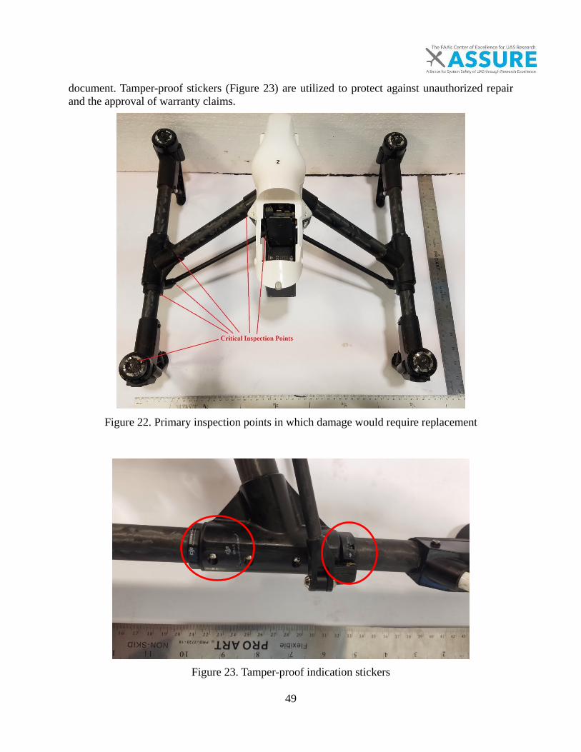
49
document. Tamper-proof stickers (Figure 23) are utilized to protect against unauthorized repair and the approval of warranty claims.
Figure 22. Primary inspection points in which damage would require replacement
Figure 23. Tamper-proof indication stickers

50
Figure 24. Overall damage to the thermoplastic structure after impact
Figure 25. Small levels of cracking at stress concentrations
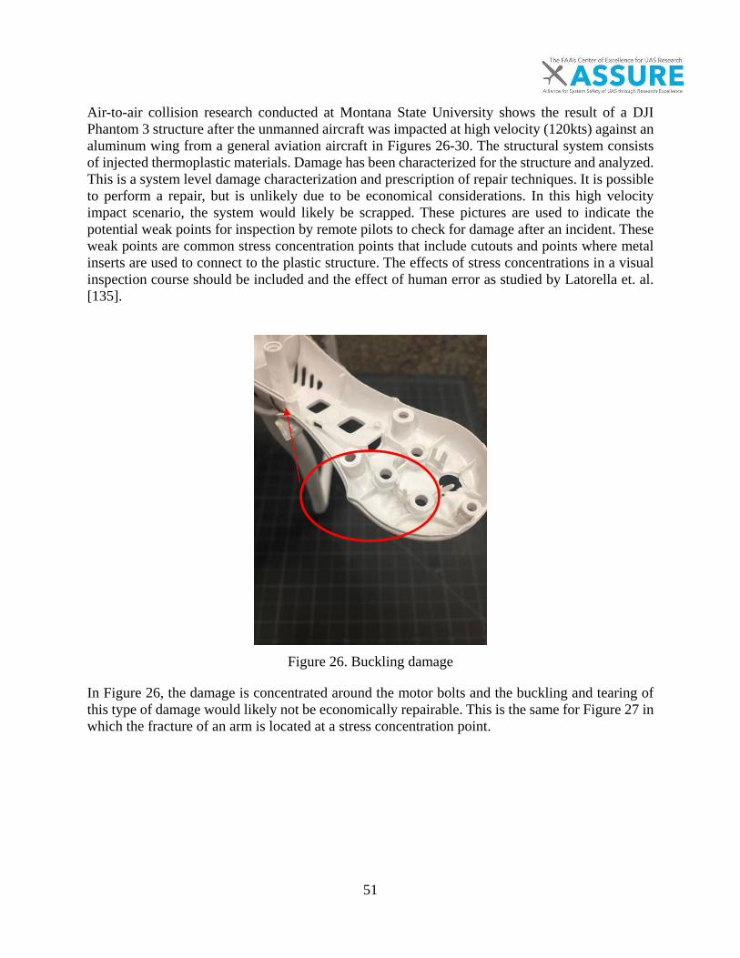
51
Air-to-air collision research conducted at Montana State University shows the result of a DJI Phantom 3 structure after the unmanned aircraft was impacted at high velocity (120kts) against an aluminum wing from a general aviation aircraft in Figures 26-30. The structural system consists of injected thermoplastic materials. Damage has been characterized for the structure and analyzed. This is a system level damage characterization and prescription of repair techniques. It is possible to perform a repair, but is unlikely due to be economical considerations. In this high velocity impact scenario, the system would likely be scrapped. These pictures are used to indicate the potential weak points for inspection by remote pilots to check for damage after an incident. These weak points are common stress concentration points that include cutouts and points where metal inserts are used to connect to the plastic structure. The effects of stress concentrations in a visual inspection course should be included and the effect of human error as studied by Latorella et. al. [135].
Figure 26. Buckling damage
In Figure 26, the damage is concentrated around the motor bolts and the buckling and tearing of this type of damage would likely not be economically repairable. This is the same for Figure 27 in which the fracture of an arm is located at a stress concentration point.

52
Figure 27. Significant unrepairable damage substantiates replacement
Figure 28. Buckling of the battery case and cracking of rotor arms
Figure 28 indicates the weak point of joints and clips in any plastic structure. It should be further noted that tests were conducted with the battery and motors installed. Figure 29 shows the effects of the motor pulling out the weakest link in the structure. This type of damage, if repaired, would need to be tested to be sure it does not affect the control of the system. Results from a test of this type could then be applied to substantiate other repairs.

53
Figure 29. Pullout damage at a fastener (motor mount)
Figure 30. Insert Separation
Inspection should take place at any fastening holes after a crash, as seen in Figure 30. If a fused joint is made between the two, the strength of the fused joint would have the same strength in this size of system as this press fit technique [97]. This assembly method of press fit inserts is used to improve manufacturability and replacement. The use of different joining techniques to perform a repair would need to be addressed.

54
4.5.1. Thermoplastics
Thermoplastic materials were damaged using a slingshot to impact a wing from the research of the ASSURE Air to Air Collision research team which is studying air to air impacts at high velocity. The DJI Phantom 3 was chosen as the baseline UAS for quad copter air-to-air collision studies. The DJI Phantom 3 primary structure is injection molded thermoplastics. The wing was from a Piper Cherokee PA28 with a short takeoff and landing (STOL) cuff. An example of impact damage to the PA28 wing from a DJI Phantom 3 with velocities up 156 kts is shown in Figure 31.
Figure 32. Damage from a DJI Phantom 3 Impact on a Piper Cherokee w/ STOL cuff
The most common damage is around stress concentrations of the systems regardless of the construction type, which should be included in any training scenario. Pre-flight visual inspection was chosen as it is the most common mode available to for inspection and the most likely mode of inspection available to most sUAS operators. The process of testing, repair, and comparison of damage in thermoplastic materials such as shown in Figures 33 - Figure 34 is ongoing.
4.5.2. Thermosets
Composite thermoset materials of a DJI Inspire 1 were damaged by a three-point bending system. These systems were then inspected for damage using visual techniques after an application of loads significant enough to break the system. (Figures 32 and 33). Damage such as this motivates the need for a minimum drop height recommended for UAS small systems for structural validation purposes. Since the intent was to recreate the available resources of a small operator, the use of NDI other than tap testing was not performed. The damage resulting from a drop of 4 feet of an Inspire 1 was negligible. The airframe was then disassembled and inspected for damage. No damage was observed other than minimal and superficial scuffing. The damage shown in Figures
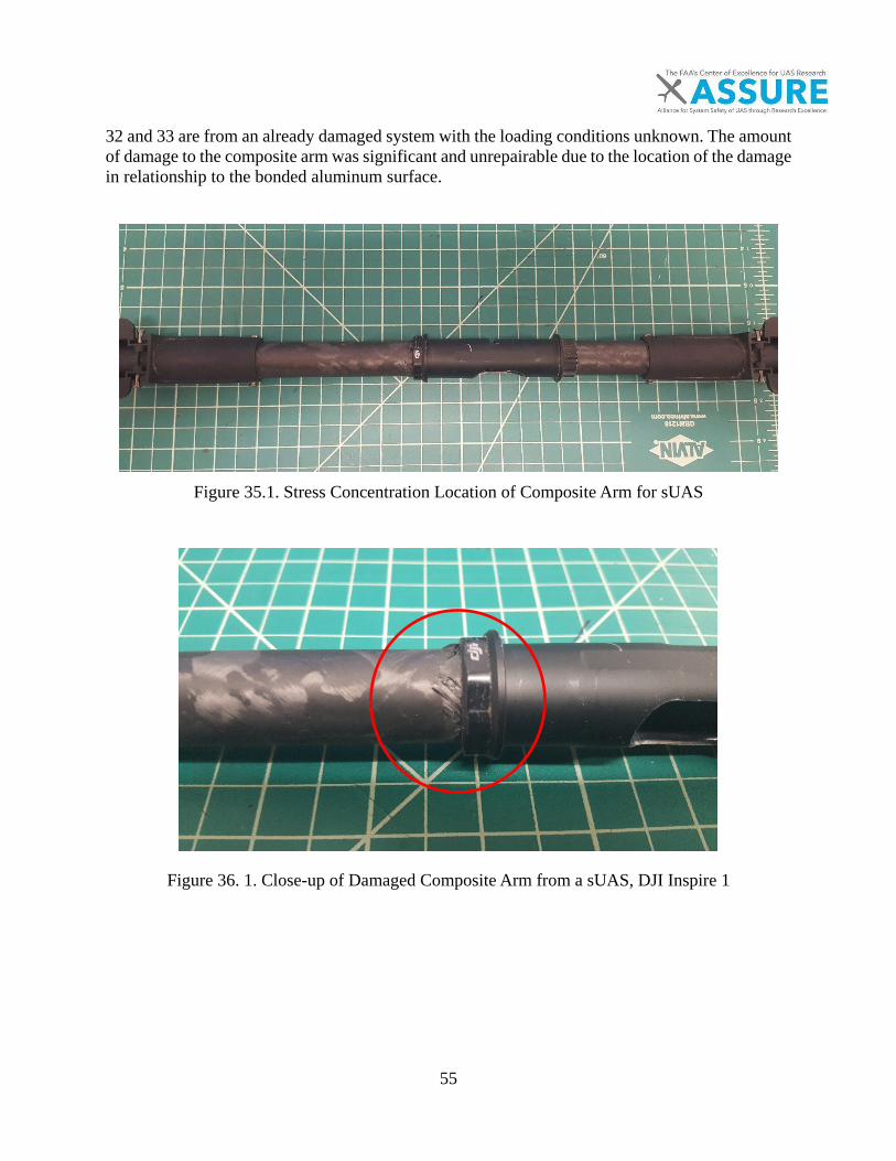
55
32 and 33 are from an already damaged system with the loading conditions unknown. The amount of damage to the composite arm was significant and unrepairable due to the location of the damage in relationship to the bonded aluminum surface.
Figure 35.1. Stress Concentration Location of Composite Arm for sUAS
Figure 36. 1. Close-up of Damaged Composite Arm from a sUAS, DJI Inspire 1
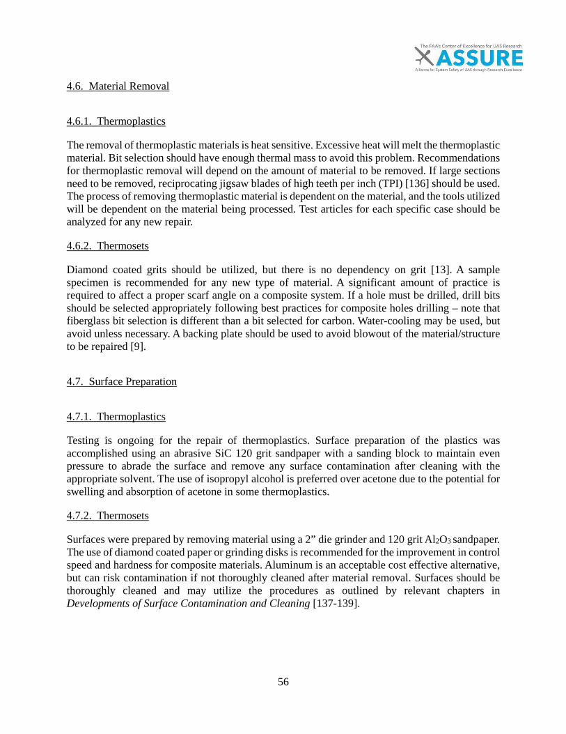
56
4.6. Material Removal
4.6.1. Thermoplastics
The removal of thermoplastic materials is heat sensitive. Excessive heat will melt the thermoplastic material. Bit selection should have enough thermal mass to avoid this problem. Recommendations for thermoplastic removal will depend on the amount of material to be removed. If large sections need to be removed, reciprocating jigsaw blades of high teeth per inch (TPI) [136] should be used. The process of removing thermoplastic material is dependent on the material, and the tools utilized will be dependent on the material being processed. Test articles for each specific case should be analyzed for any new repair.
4.6.2. Thermosets
Diamond coated grits should be utilized, but there is no dependency on grit [13]. A sample specimen is recommended for any new type of material. A significant amount of practice is required to affect a proper scarf angle on a composite system. If a hole must be drilled, drill bits should be selected appropriately following best practices for composite holes drilling – note that fiberglass bit selection is different than a bit selected for carbon. Water-cooling may be used, but avoid unless necessary. A backing plate should be used to avoid blowout of the material/structure to be repaired [9].
4.7. Surface Preparation
4.7.1. Thermoplastics
Testing is ongoing for the repair of thermoplastics. Surface preparation of the plastics was accomplished using an abrasive SiC 120 grit sandpaper with a sanding block to maintain even pressure to abrade the surface and remove any surface contamination after cleaning with the appropriate solvent. The use of isopropyl alcohol is preferred over acetone due to the potential for swelling and absorption of acetone in some thermoplastics.
4.7.2. Thermosets
Surfaces were prepared by removing material using a 2” die grinder and 120 grit Al2O3 sandpaper. The use of diamond coated paper or grinding disks is recommended for the improvement in control speed and hardness for composite materials. Aluminum is an acceptable cost effective alternative, but can risk contamination if not thoroughly cleaned after material removal. Surfaces should be thoroughly cleaned and may utilize the procedures as outlined by relevant chapters in Developments of Surface Contamination and Cleaning [137-139].

57
4.8. Material Replacement and Testing
4.8.1. Thermoplastics
The material replacement of thermoplastic materials is straightforward once the material and the proper temperatures have been determined. The preferred methods are low cost system consisting of a temperature controlled electrical resistance heater.
4.8.2. Fiber Reinforced Thermosetting Polymer Repair
In this section, more is discussed on field repairs. Mechanical performance of the field repair, and expectations for the efficacy of the repair are provided. Scarf repairs use shear to transfer load into the system [54]. The intent of a scarf repair is to create a flush or aerodynamic surface of the repair. These types of repairs are common where a surface needs to be aerodynamically smooth or where weight or geometry constraints preclude simple patches. The repair process for the material was used to create a repair in which a Digital Image Correlation (DIC) system was used to characterize the strain state of a through composite repair on a 30mm x 300mm composite coupon. DIC is a sub-pixel image correlation technique used to obtain full-field displacements and strains [39]. The methods utilized for digital correlation may also be used to validate the material removal to the planned amount of removal in critical repairs. The entire process is shown in Figures 34-39. The composite specimens were drilled using a 3/8inch carbide low angle drill bit to reduce delamination. A 2° scarf angle was then applied and tested in uni-axial tension according to an ASTM D-3039 test standard [140]. Additional comparison for tensile tests of scarf repairs have been developed by Ahn and Caminero [24, 59]. The same resin was utilized for the base material in this case a Hexion Rimr 135 Rimh 135 mixed at 100:33 parts by weight. In Figure 34, this can be seen as the green area around the tube on the surface of the laminate. The fabric was applied by hand layup and then a vacuum was applied at room temperature for 24 hours, after which the samples were demolded and cured for an additional 12 hrs in a 70°C oven. Samples were sanded and then tested in an electro servo-hydraulic testing machine with hydraulic grips at 3000psi to tabbed specimen as shown in Figure 40. The circular as-cured patches shown can be seen in Figure 36.
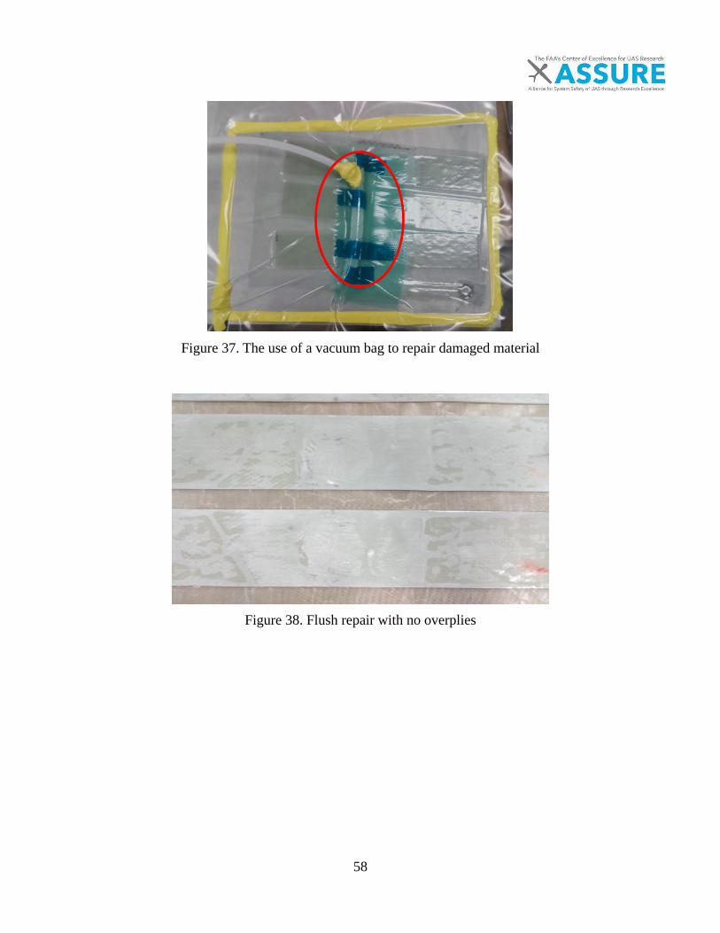
58
Figure 37. The use of a vacuum bag to repair damaged material
Figure 38. Flush repair with no overplies
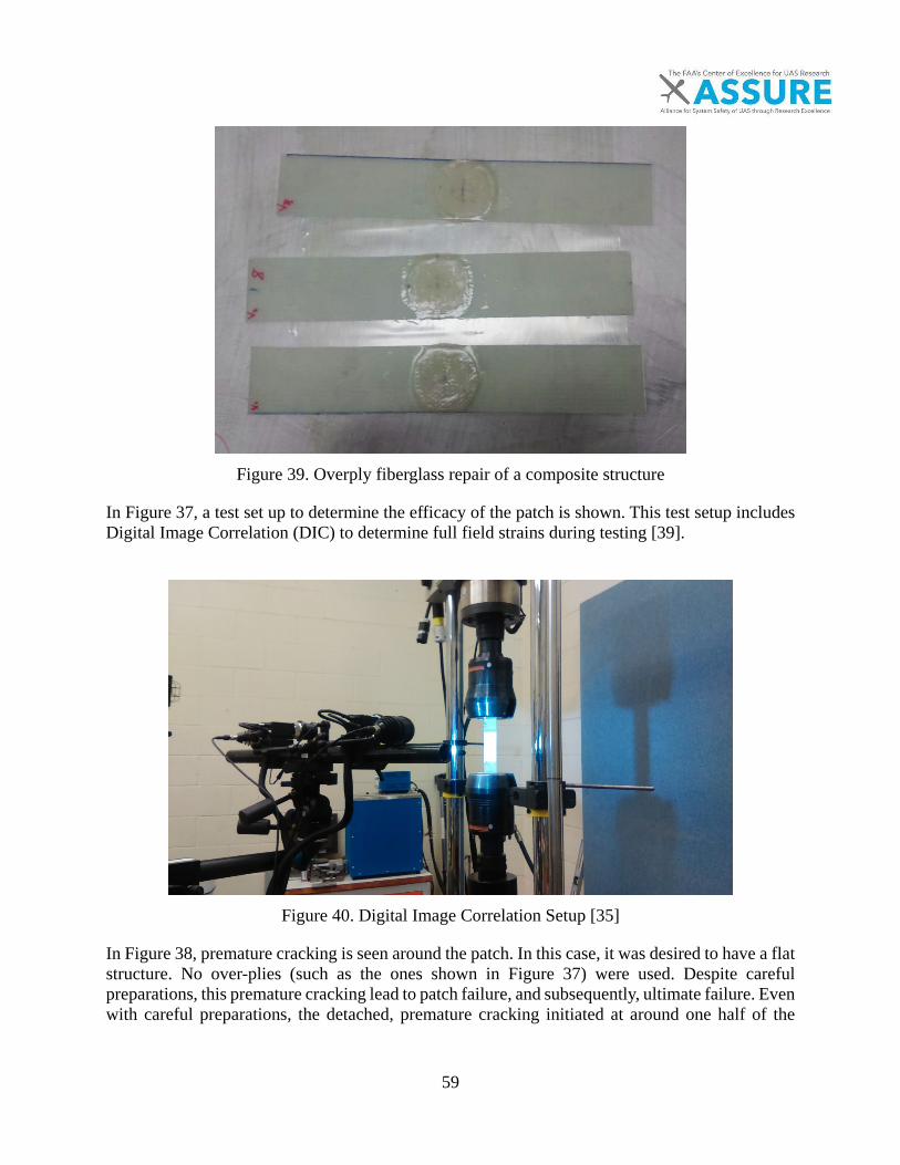
59
Figure 39. Overply fiberglass repair of a composite structure
In Figure 37, a test set up to determine the efficacy of the patch is shown. This test setup includes Digital Image Correlation (DIC) to determine full field strains during testing [39].
Figure 40. Digital Image Correlation Setup [35]
In Figure 38, premature cracking is seen around the patch. In this case, it was desired to have a flat structure. No over-plies (such as the ones shown in Figure 37) were used. Despite careful preparations, this premature cracking lead to patch failure, and subsequently, ultimate failure. Even with careful preparations, the detached, premature cracking initiated at around one half of the

60
parent laminate strength. (Note the high contrast speckle pattern, which is used for reference in the DIC.)
Figure 41. Indication of insufficient shear strength
Progressive strains are shown in Figure 39. Areas of green are nominal, average strains, and areas of red are high strain regions leading to premature failure of the bonded repair.
Figure 42. Strain concentrations of a repaired system with no overplies
The image on the left of Figure 39 shows the initial strains (red is high, green is nominal). There are some strain concentrations seen at the beginning of the test, but these become more evident later in the test, as shown on the right of Figure 39. The angle of the repair bevel, or the scarf ratio, is a topic of discussion. Ideally the larger the scarf ratio the better, but in practice this is hard to achieve for a number of reasons, including the non-

61
planar surfaces and the lack of available area to allow for the ideal scarf ratio due to the location of the damage. These types of damage may preclude the use of this technique if the damage is severe enough, and location presents difficulty in managing a reliable repair. This idealized repair is being followed up with less idealized repairs. The use of an additional plies (overplies) of material to return the strength to an as built condition should be utilized with caution. If additional plies are added to meet strength conditions and a flexural or torsional load is applied, the edges of the repair may delaminate. If the damage of the laminate/structure is in a highly loaded region, it is recommended to use overplies as was shown in Figure 13. Each of the two common construction methods for advanced composites, sandwich and solid construction, have different methods for repair. A solid laminate is generally easier to repair than a sandwich composite. Solid constructions are found on a range of unmanned aircraft and may be constructed through pre-preg operation or the use of a roll wrapping technique for tubes. Sandwich construction would be utilized for higher performance structures and their repair has been studied by previous FAA sponsored research for flat surfaces[10, 27]. Once the damaged material has been removed, and the surface sufficiently cleaned, an adhesive layer is placed of the same type of resin system as the repair plies are added. Then the appropriate extra plies are added and a recommended outer sanding layer of low areal weight fiber glass is used to help with painting after the damage has been fully validated and inspected. A sandwich construction (face sheets and a core) is more difficult to properly repair. Additionally, most damaged composites of this type may have a damaged honeycomb or core with trapped moisture in the system. This scenario would require the drying of the composite, using vacuum and heating pad moisture removal. A bonded thermoset is uses an adhesive to bond two materials together. The design of the joint is critical as the bond relies on the shear strength of the adhesive to transfer load between the two structures. These types of bonded repairs are useful for curved surfaces. The design of a bonded joint is dependent on the structure [39]. Considerations of materials should be taken into account to avoid thermal mismatch of the two bonded materials and the loading environment. Additionally, common bonding adhesives include thin film, film with a carrier cloth to control bond thickness, liquid, paste, and core splicing types. Examples of these types of adhesives are described by [141, 142]. Paste resins are useful for systems with vertical surfaces, but are more prone to trap air than liquid resins due to their higher viscosity. For all resins that are mixed, care should be taken to not to incorporate air into the mixing of the system.[50, 53] Incorporated air will have a severe effect on the bonding strength of the adhesive to the substrate and will acts as a void, significantly reducing the strength of the adherent. Patch repairs are ideal for thin laminates in which a bolted repair may cause shear out of the material. These types of repairs are not aerodynamically efficient and should not be used on structures in which aerodynamics is of concern. These repairs are simpler to perform than a scarf repair when the composite system is under constrained growth or no growth criteria. The types of adhesives utilized will affect the bond-line of the material, which is a critical factor in determining the quality and strength of the material. The typical thermosetting adhesives are of
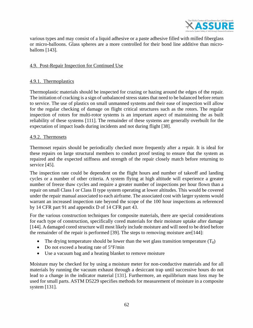
62
various types and may consist of a liquid adhesive or a paste adhesive filled with milled fiberglass or micro-balloons. Glass spheres are a more controlled for their bond line additive than micro-ballons [143].
4.9. Post-Repair Inspection for Continued Use
4.9.1. Thermoplastics
Thermoplastic materials should be inspected for crazing or hazing around the edges of the repair. The initiation of cracking is a sign of unbalanced stress states that need to be balanced before return to service. The use of plastics on small unmanned systems and their ease of inspection will allow for the regular checking of damage on flight critical structures such as the rotors. The regular inspection of rotors for multi-rotor systems is an important aspect of maintaining the as built reliability of these systems [111]. The remainder of these systems are generally overbuilt for the expectation of impact loads during incidents and not during flight [38].
4.9.2. Thermosets
Thermoset repairs should be periodically checked more frequently after a repair. It is ideal for these repairs on large structural members to conduct proof testing to ensure that the system as repaired and the expected stiffness and strength of the repair closely match before returning to service [45]. The inspection rate could be dependent on the flight hours and number of takeoff and landing cycles or a number of other criteria. A system flying at high altitude will experience a greater number of freeze thaw cycles and require a greater number of inspections per hour flown than a repair on small Class I or Class II type system operating at lower altitudes. This would be covered under the repair manual associated to each airframe. The associated cost with larger systems would warrant an increased inspection rate beyond the scope of the 100 hour inspections as referenced by 14 CFR part 91 and appendix D of 14 CFR part 43. For the various construction techniques for composite materials, there are special considerations for each type of construction, specifically cored materials for their moisture uptake after damage [144]. A damaged cored structure will most likely include moisture and will need to be dried before the remainder of the repair is performed [39]. The steps to removing moisture are[144]:
• The drying temperature should be lower than the wet glass transition temperature (Tg) • Do not exceed a heating rate of 5°F/min • Use a vacuum bag and a heating blanket to remove moisture
Moisture may be checked for by using a moisture meter for non-conductive materials and for all materials by running the vacuum exhaust through a desiccant trap until successive hours do not lead to a change in the indicator material [131]. Furthermore, an equilibrium mass loss may be used for small parts. ASTM D5229 specifies methods for measurement of moisture in a composite system [131].

63
5. RECOMMENDATIONS
The recommendations are given for both the materials construction type and the risk classes as developed by Clothier [12]. The reason for the divisions is to capture the groups that have distinct requirements for the repair to reduce the risk of failure. The risk level then establishes the rigor necessary for the inspection, maintenance, and repair of the systems. These risks of repair and maintenance are generally low for small systems. For large systems, the requirements are met by the current standards for manned aviation for the inspection, maintenance, and repair of composite systems, albeit at higher costs Materials and manufacturing procedures not common to current aircraft structures need more research for repairs and maintenance.
5.1. Maintenance Training Requirements
5.1.1. Thermoplastics
For the repair of thermoplastic materials, the training should focus around the identification and likely causes of damage. Training should center on the basic requirements for the inspection of a system after an incident, the return to service requirements, the use of a logbook for maintenance, and the disposal of a system if damage is unrepairable. Documents including the visual inspection AC would be helpful for a sUAS pilot [106, 110]. Training should furthermore include how to acquire replacement parts and install these parts to return the system to as built safety levels for commonly damaged parts such as rotors for small multi-rotor systems.
5.1.2. Thermosets
The training requirements for thermoset materials, typically composites constructions, should follow the same requirements of manned aviation regardless of the size of the system. If a composite is to be repaired, there is a minimum amount of training required to perform an effective repair. This would favor the replacement of damaged parts on small systems to maintain the same safety level as set by the original manufacturer if the damage affects a structural component’s reliability. All maintenance and repair, regardless of size, should utilize a logbook. These logbooks could either be electronic or paper records and would ideally adhere to 14 CFR part 43 [14]. If captured, the reporting of incidents and damage will generate repair data and methods that are utilizable across a number of repairs. Furthermore, a significant amount of research has been done into the validation of the most common construction techniques found on UAS systems. This repair research may be utilized as a reference when a structural repair manual is non-existent, which is the common case for sUAS repairs.
5.1.3. sUAS Part 107
A repair could be made acceptable if an FAA Designated Airworthiness Representative or Designated Engineering Representative specifically verifies that the repair was conducted using best practices. This trained witness designation could be a part 65 repair designation, which would cover the required training for the repair of these small systems for non-metallic materials.

64
Additionally, the approval of the manufacturer for the replacement of parts could be an alternative option if the cost of a part 65 repair is greater than a replacement of a part only. Although a separate designation could be made for the repair of non-metallic materials, the current qualifications of a part 65 repairman would create multiple standards. However if implemented, a sUAS certification could be implemented similar to a DER designation for manned aircraft [132]. A commercial parts list for sUAS structural parts would allow for the use of replacement parts within the scope of Part 107 regulations. This could be similar to the current list of approved section 333 UAS systems[23]. This requirement could be met by a similar process the distribution program covered by AC00-56B Voluntary Industry Distributor Accreditation Program [145]. However, the AC00-56B falls under the type certification process of which UASs are not included. Further AC that are referenced by AC00-56B are listed below in Table 19. Table 19. Related Advisory Circulars to Replacement of Parts AC Number Description of AC
AC 20-62 Eligibility, Quality, and Identification of Aeronautical Replacement Parts, contains guidance and information regarding the eligibility of aeronautical parts and materials for installation on U.S. type certificated products.
AC 20-142
Eligibility and Evaluation of U.S. Military Surplus Flight Safety Critical Aircraft Parts, Engines, and Propellers, provides information and guidance for use in evaluating and determining the eligibility of U.S. military surplus flight safety critical aircraft parts (FSCAP), engines, and propeller for installation on FAA type certificated products.
AC 21-2
Complying with the Requirements of Importing Countries or Jurisdictions When Exporting U.S. Products, Articles, or Parts, contains the special airworthiness requirements that foreign Civil Aviation Authorities (CAA) have provided to the FAA.
AC 21-29 Detecting and Reporting Suspected Unapproved Parts, contains guidance and information regarding the detection and reporting of suspected unapproved parts.
AC 21-43
Production Under 14 CFR Part 21, Subparts F, G, K, and O, provides information for Production Approval Holders (PAH) under Title 14 Code of Federal Regulations (14 CFR) part 21, Certification Procedures for Products, Articles, and Parts.
AC 21-45 Commercial Parts, explains how you can use the provision in 14 CFR part 21, §§ 21.1(b)(3), 21.8, 21.9(a)(4), and 21.50(c), for commercial parts.
AC 21-46 Technical Standard Order Program, contains guidance and information on the Technical Standard Order (TSO) process for manufacturers producing articles and appliances under a TSO Authorization (TSOA).
AC 21.303-4 Application for Parts Manufacturer Approval Via Tests and Computations or Identically, contains guidance and information to applicants for Parts Manufacturer Approval (PMA) of articles.
65
AC Number Description of AC
AC 43-9
Maintenance Records, provides information regarding maintenance record requirements under 14 CFR parts 43 and 91, §§ 43.9, 43.11, and 91.417, and the related responsibilities of owners, operators, and persons performing maintenance, preventive maintenance, and alterations on U.S. type certificated products and their component parts.
A systems analysis of a manufacturer of unmanned systems supply chain would be required to see if these systems align with the suggestions set forth by AC00-56B. If a manufacturer adheres to ISO-9001 standards, the quality management system requirements would be met. For the operation of unmanned systems over people, adherence to ISO-9001 or other equivalent standards would improve the safety of the non-involved public for non-metallic structures. Also cited by AC00-56B are the FAA Orders 8111.42 Parts Manufacturer Approval Procedures, Order 8130.21 Procedures for Completion and Use of the Authorized Release Certificate, and Order 8120.22 Production Approval Procedures. AC21-45 Commercial Parts covers only specific non-failure critical commercial parts and could be utilized for small systems. Limitations in using for the purpose of structural components by AC 21-45 as written are summarized in the lists below. A list of items allowed only use by the FAA are:
• Departures from specific policy and guidance • Use of new and unproven technologies • Equivalent level of safety findings • Special conditions • Exemptions • Establishment of a product certification basis • TC, PMA, TSOA • Determination of an unsafe condition
For structural substantiation these tasks are additionally reserved to the FAA
• The approval of test plans • Basic load reports • Material and fastener allowable, including fatigue allowable • Approval of life limits • Previously unapproved crashworthiness matters • Damage tolerance evaluation methodologies • Airworthiness limitations section of the instruction for continued airworthiness • Approval of probability conclusions
For propellers (rotors of small unmanned aircraft)
• Approval of test plans • Operational limits • Vibration analysis modes
66
• Airworthiness limitation sections• Fatigue allowable and fatigue life• Load reports, particularly vehicle usage spectra
Furthermore, the limitations of AC21-45 applied to structural components include the applications of safety analysis by engineering techniques below.
Safety analysis is defined by some of the following and not limited to: • Functional hazard analysis (FHA)• Preliminary system safety assessments (PSSA)• Failure mode and effects analysis (FMEA)• Fault tree analysis (FTA)• Markov analysis (MA)• System safety assessment (SSA)• Zonal analysis (ZA)• Common mode analysis (CMA)• Particular risk analysis (PRA)• Evaluation of the need for warning information in response to unsafe operating
conditions
5.2. Practical and Knowledge Test Standards for Non-Metallic Structures
The practical knowledge and test standards for the repair and maintenance of UAS systems should align with current techniques for the repair of non-metallic materials. These include the standards for composite repair as developed by SAE and other training program recommendations developed by the FAA [50]. The basics of the practical knowledge for thermoset materials should include the elements in Table 20.
Table 20. Practical and knowledge test standards for thermoset materials Test matter Description
Inspection The common types of inspection techniques, lighting requirements for visual techniques, NDI for large systems
Structure preparation Protection of delicate electronics, e.g. motors, circuit from dust and heat
Material removal Selection of tools, methods for creating a scarf Surface preparation Basics of surface cleaning, effects of moisture Material selection and handling Proper mixing of thermosets, moisture and contamination effects
Replacement of material Layup preparation, vacuum bagging requirements
Application of cure The types of heating, heat blankets, ovens, etc.
67
Test matter Description Return to service requirements
Proof testing, environmental protection, entry into maintenance records, and how to conduct test flights
Effects of human factors PEAR (people, environment, actions, resources) model
Health, safety, and environment Selection of proper dust and ventilation guides
For the repair of thermoplastic materials, practical knowledge tests should include items from Table 21.
Table 21. Practical and knowledge test standards for thermoplastic materials Test matter Description
Inspection Description of crazing, cracking, lighting requirements, and damage bending on mechanical properties
Material removal Selection of tools compared to thermosets Surface preparation Cleaning and priming a surface for bonding Material selection Properly identifying and selecting an Methods of repair Fusion bonding, and recommendation against bonding methods Application of heat Electrical, mechanical, Return to service requirements
Proof testing, entry into maintenance records, and conducting test flights
Effects of human factors PEAR model
Health, safety, and environment Disposal of solvents, power tool operation, etc.
As an example of practical knowledge of thermoset material handling, a filler should never be added last to a 2-part system such as epoxy because fillers will affect the cure rate of the most common thermosetting materials [146]. Curing tests should be performed before a repair to validate the expected cure properties of the resin. An example of a practical knowledge for thermoplastic material handling would be the effects of the application of heat and thermal degradation [147]. Cracks to non-structural plastics may be repaired using resistance welding techniques with good return of strength once the thermoplastic material has been identified.
5.2.1. Class I
Currently for the smallest systems, the size of the system makes it possible to ship the system to the manufacturer at a minimal cost compared to transporting manned aviation structures. As such, the knowledge of repair and the manufacturing practices are generally not published by the consumer level systems as they are intended to be returned to the manufacturer for disposition relative to repair or replace.
68
The general scope of the operation of these systems may preclude the user from having or needing to seek the required training to fully understand the systems construction to be able to repair the system back to the original condition. However, the pilot in command should understand the implications of not replacing rotors or performing necessary maintenance on a control surface as a high risk factor for flight. Any training for maintenance should center on the need to inspect the system at specified intervals, in addition to a pre-flight inspection. From a part identification standpoint, the system of station marking is not utilized for small unmanned aircraft. Parts numbers are much smaller for these sUAS than manned aviation. Although the use of station markings would help to identify specific joints and bonds of part assemblies for inspection points, a visual guide would be sufficient to reduce the amount of human error involved in the inspection routine of a system. Recommendations of common parts susceptible to damage are listed in Table 22. Table 22. Common areas to inspect for damage Part Material type Common damage Safety critical (Y/n) Rotors Thermoplastic Bending Yes Arms Composite/Epoxy Cracking Yes Electronic fairing Thermoplastic Cracking No
A pre-flight visual inspection of the points is recommended and aligns with Part 107 requirements [34]. The time required to perform a visual check is less than 15 minutes. If damage is inspected, the part could be isolated and replaced by an authorized representative of the manufacturer or the manufacturer to return it to its original level of safety. When possible, parts should be removed to avoid contamination of electronics or the electronics should be sufficiently shielded from dust during material removal. Thermoplastics should be repaired using simple techniques for non-critical safety unrelated parts. Parts that are structural can be repaired by a trained technician with fusion welding techniques. Rotors may be replaced by the user, but never repaired. Their cost is low enough that the additional risk from repair is not worth the cost. Thermoset parts should be replaced as stress concentration operating environments and often the lack of material knowledge contribute to the safety uncertainty of a damaged part.
5.2.2. Class II, III
The requirements for the maintenance and repair of these systems should reflect the increased risk. More training will be required, and due to the size and location, shipping of the system to the original manufacturer may not be economical. However, for some systems, this may be the preferred method if shipping is economical. The recommended practice for the repair and maintenance of these systems should reflect the increased risk of not operating under the section 333 blanket COA. A structural repair manual should be supplied with the delivery of these systems if they could potentially operate over people. ASTM best practices could be utilized for these systems, even though these requirements are a little below part 145 requirements for maintenance personnel. Major and minor repair alterations
69
are defined in Section 1.1. and Appendix A of 14 CFR part 43. Principle structural elements should be defined for the structure within the manual. If a principle structural element is damaged then an approved repair station should conduct the repair. Examples of a principle structural element (PSE) are included in AC 25.571-1D Damage Tolerance and Fatigue Evaluation of Structure [17].
5.2.3. Class IV, V
The risk of these systems to the National Airspace based on their CONOPS requires the same level of maintenance and documentation as manned aviation. This requirement would lead to integration into the national airspace for the maintenance and repair of non-metallic materials. This would include the relevant requirements such as the part 145 repair station or part 65 repairman requirements. This would also require the establishment of a designated engineering representative (DER) under the Title 49 and Title 14 part 183.
5.2.4. Small Unmanned Systems
The small, unmanned systems bridge the gap between Class I and Class II systems. These systems will vary in their construction and complexity. However, for any structural member, these systems should ideally be replaced if the part is structural. Simple repairs could be performed on minor damage if to a primary structure, but these limits would need to be defined based on the flight characteristics. This is the general current practice in which parts are replaced as assemblies from the manufacturer in lieu of field repairs. The warranty could additionally serve as a tool for investigators of incidents should tamperproof devices be utilized or required for the manufacturer of sUAS systems.
5.3. Return To Service Requirements
For thermoplastic and thermoset systems, the easiest requirement would be substantiation of the static structure through any number of tests. The repair should be loaded under the expected conditions of flight including a Safety Factor after each repair. This would be simple to perform for small systems as the loads will be much lower than large systems. These tests scenarios exist for manned aviation and proof testing of the structure would be an economical option for small systems.
5.3.1. Class I
For the return to service of small systems, these should be related to the operation to be performed by the device. If the concept of operations risk is high, then the complete structural system should be checked over by a certified repair station or mechanic before operation of the system is continued. After the replacement of a structural part, the system should undergo flight tests in a controlled environment.
70
5.3.2. Class II, III
Depending on the construction and type of damage, return to service requirements should be different. The major and minor repair structure would be a convenient delineating factor for the requirements of approval for a return to flight. These repairs should be independent of the location in which the aircraft is operating. The cost of these systems would substantiate a higher level of scrutiny for return to service requirements.
5.3.3. Class IV, V
The size and potential risk of these systems to the National Airspace System (NAS) warrants a similar process to manned aviation for the validation and repair of these systems. Currently, the repair of these systems mirrors the manned aviation standards for non-metallic systems. This is enforced by the primary operators of these large systems through a Structural Repair Manual, which should be provided with all unmanned aircraft of this size. Significant damage may fall outside the repairable design limit (RDL). This amount of damage could make safe repair an unviable route to return the system to the as manufactured safety level and flight characteristics. Any major repair should utilize the reporting requirements of the FAA form 337. Regardless of operational environment, civil aircraft should utilize an appropriate and certified repair station for additional NDI and the repair of the system.
5.4. Technical Documentation Requirements
The maintenance record requirement of 91.417 would be applicable to the maintenance of all UASs. This includes the reporting requirements of 43.11 and 43.9. The description of the work performed should cover the basic reporting requirements of the part 43 requirements including the methods, name of personnel, and procedures. Applicable procedures could include the CHM-17 handbook, AC43-1B and AC20-107 [7, 14, 118]. These requirements are required by the section 333 exemptions and suggested by the Part 107 sUAS requirements [23, 34].
5.4.1. Class I
All systems, regardless of size, should keep maintenance logs. For small systems, a mission log should be kept and include a line for any rotor replacement or incidents in which a loss of control was experienced. This would help to inform periodic check of specific parts or areas on the UAS. Ideally, this mission logging system would be an electronic copy as an electronic system would allow for easier data transfer and query requests between the user and interested parties. If flying under a section 333 exemption, the mission log is a requirement and should be reported.
5.4.2. Class II, III
This is where the economic value of cost versus safety will be a difficult to evaluate as it will be structurally dependent and these systems have long flight times and unknown flight envelopes. If a critical structure is determined to be damaged, then the repair should be proof tested before allowing access back into the national airspace. Some of the systems may be rotorcraft and some
71
of these systems may be fixed wing, but all tests should be performed in a controlled environment compared against a known test standard.
5.4.3. Class IV, V
These systems should meet standard composite directives of a CFR part 43 and CFR part 135 regulations. Replacement parts should be produced by a manufacturer that holds an FAA parts manufactures approval and all repairs should be performed by a certified part 65 mechanic with the appropriate airframe rating [148]. It is unlikely that these systems will be of a multi-rotor type and will generally be fixed wing, high endurance systems with either jet based or a turboprop design. With these UASs’ high performance based design in mind. some specific repair schemes of these systems could be approved based on previous data [8]. This would allow DER to reduce the regulatory burden placed on the FAA.
5.4.4. Additional Recommendations
The scope of the project from the outset was changed to cover the broad class of non-aerospace composites and thermoplastic materials to reflect the state and construction of UAS systems which are shifting towards lower cost, consumer technology. The use of these materials is a new field that does not have the same level of research or use that composite materials have in aerospace as a structural material. Additionally, a better understanding of lower cost thermoplastic composite materials outside the high performance thermoplastics such as PEEK and PEI [85, 149] should be considered. There is a need for increased understanding of these lower cost thermoplastic materials as they continue to gain acceptance in the commercial UAS marketplace. In the scope of composite materials, there is a good understanding for continuously reinforced composite materials as they relate to reparability and maintenance. However, compression molded long fiber composites made of thermosetting or thermoplastic materials may find use on small to medium sized UASs; therefore, there is a need to understand the inspection and repair for these systems as they relate to unmanned aircraft [150].Finally, there is a need for the understanding of hybrid constructions in which a continuous thermosetting structure is over molded with functionality, including bosses and inserts for fasteners in both thermoplastic and thermoset composites [151].
72
6. SUMMARY AND CONCLUSIONS
Unmanned systems take on two forms: commercial systems, in which cost is minimized and ease of use is maximized, and military or high performance adaptations, in which mission capabilities are prioritized over the ease of use and the cost of the system. There are multiple ways to define the systems, but size appears to be the best way to differentiate between systems. The methods of construction are varied, but they fall into two categories: systems that use thermoplastic materials and systems that use thermoset materials. These sUAS require standards for proven structural repair methods. For most small systems, the proper maintenance procedure is replacement by the manufacturer or a similarly skilled maintainer. A qualified maintainer, who has a quality control system that would return the system to level of safety equivalent to that of its as manufactured state, could serve in place of the manufacturer. The maintenance of these systems will require accurate and timely damage detection by the inspector whose tools may be limited to simple techniques of visual inspection and tap testing. Which is why training for small systems should center on the inspection and detection of damage that would affect the structure and flight safety of the system. For larger systems that operate in a higher level of the National Airspace, construction methods and defined risk to the public mean that the well-established FAA regulations for the maintenance and repair of these composite systems need to be followed [7, 122]. Using updated rules from general aviation for fixed wing aircraft, which are performance based rather than prescriptive based, would reduce the regulatory burden to the FAA. This recommendation echoes the current efforts to update the Part 23 requirements [161]. As of this writing, airworthiness certification criteria for any UAS operating in the NAS are still pending. The repair of these systems is well studied and reflect the results of a multitude of researchers who indicate that a distinction should always be made by the material type because identification is critical for a quality repair. The key points affecting any repair should include:
• determination if damage is repairable • damage inspection • a clean surface • removal of surface contamination • moisture removal • curing parameters • material selection for the repair • inspection and return to service requirements
Special considerations need to be made for material identification for thermoplastics and for thermosets because different procedures are required for removal and preparation of the surface to appropriately distribute the load through the patch and the structure. Training for the repair of thermoplastic materials has been extensively studied. This documentation serves as a valuable resource for any thermoplastic repairs, and when possible test cases should be made when unsure whether a repair or replacement is appropriate. For small systems, the use of

73
thermoplastics will most likely continue to dominate the market because low cost production methods can still meet the structural needs of these systems for a high volume of production. Training of personnel for thermoset repair should follow suggestions made by several FAA sponsored publications. Size specific ratings could be included for small and large systems, but the repair process will remain the same. Training for systems related to the use of analytical NDI techniques is not as necessary because repairs are unlikely to be performed on small systems due to the cost of performing the inspection using ultrasound or other analytical NDI techniques. These techniques may be reserved for large military systems, when the cost of repair, even if substantial, is less than the cost of the replacement of the part or system. Non-metallic repair is an art form for manned aircraft, and each repair will be different. The skill and training of the repair personnel is crucial as the reliability of the repair depends on their ability to detect damage and perform adequate maintenance. In this report, several significant issues specific to UAS maintenance and repair have been identified and discussed. Repair techniques unique to the UAS world been identified and discussed through the description of AC’s, orders, and technical reports.
74
7. FUTURE WORK
There is a disconnection between repair needs and previously developed repair techniques. What is needed is a thorough and rigorous study for applying the existing and recommended repair procedures and quantifying them relative to as-manufactured UAS structures. This work will provide a clear indication of the efficacy of the repertoire of established repair techniques, some with more emphasis on cosmetics rather than structural needs. Once this has been done, the development of a technician certification program is necessary. Montana State University and other institutions in the ASSURE team are prepared to develop repair procedures and recommendations, and to conduct maintenance technician workshops for non-metallic structural repair. More specific recommendations for future work are described below. Moreover, the definition of an approved rotor for multi-rotor UAS should be established. Research into the reliability of composite and thermoplastic rotors would help to improve the flight safety of the system, including specific processes for checking the damage after an incident or crash. These requirements could be similar to some of those found in the 14 CFR part 21 requirements or similar to those found in FAA Order 8110.42D Parts Manufacturer Approval Procedures. An aerospace forecast predicts 7 million unmanned systems by 2020. If the trends of small UAS continue to hold for most operations [152], the need for non-metallic structural repair procedures will be even more important. Ideally, these repair procedures and approved methods for non-metallic repairs would be included in a handbook or guide available to part 65 mechanics and part 145 repairs stations. As early 2017, 30,000 pilots have started the Part 107 remote pilot process. For each section, a portion is dedicated to maintenance and repair. For any repair, the return of the system to exact functionality, as designed, is ideal. For advanced composites, this is difficult and time consuming to do. Training pilots to inspect systems more regularly should be emphasized as drones could pose significant risk to the National Airspace. A structural repair manual (SRM) is delivered with all type certified aircraft. This is not the case for small, unmanned systems as the manufacturer will generally perform the repair. Designation should be made for when it is acceptable to perform a field repair versus a manufacturer repair. It would be ideal to define a risk based rating system for a repair for unmanned systems in the future. However, as design certification for small systems has not been defined, there should be continuing research on the effects of weight-based criteria for managing the risk of a system. If systems continue to trend toward the maximum limits of the Part 107 rules (55lbs) without airworthiness certification criteria, manufacturers may begin to design riskier systems—ones that increase the mission payload and capabilities while maintaining the same weight. A comprehensive survey of unmanned systems will never be complete given the nature of the industry. However, the prediction is that manufacturers will continue to use structural best practices to design systems. For systems flying under Part 107 regulations, designs are varied so consideration should be given to all kinds of materials, including recovery systems and frangible systems which usually include expanded foams or non-metallic materials. Requirements and definitions for these materials is needed.
75
For larger unmanned aircraft that are manufactured to general aviation standards, these systems will require a different approach. A typical repair can take on many forms and the qualifications that are required are stated by 14 CFR part 65. The general best practices are given by SAE training documentation, which is appropriate for both manned and unmanned structures for composite materials. High altitude long endurance, or even persistent systems of exceptionally low weight, will need to have defined inspection schedules in which their relatively large wingspan and low weight will have special considerations for their use in the National Airspace System. For non-composites of filled thermoplastics, documentation is lacking for specific aerospace training, but exists for literature [62, 63, 77, 82]. Trial repairs of these systems will follow best composite practices. This area of research is a mature field with methods and protocols developed for these systems, but should still be re-visited for applications to UAS. Testing should be performed on UAS for airworthiness criteria, as they become established. For an impact scenario, an impact of energy equivalent to falling out the sky which would lead to catastrophic damage elsewhere on the system could be considered. In small systems, the composites are not the weak link as designed. However, if a system is to be certified, an applicable standard could be established where drops from a specified distance on a hard surface would reduce the likelihood for the system failure. As such, a standard could be developed to simulate crash damage under normal use and cover a majority of incidents. Again, this all relates to the need for airworthiness certification criteria for UAS. Current non-metallic repair training for maintenance technicians can be broken down into two tasks, non-structural and structural repairs, which generally fit into the FAA’s description of minor and major repairs. Replacement of a part under a certain weight will almost always be the most economical design choice for safety if the effects of weight balance, flutter, and vibration are to be avoided. For larger systems, the appropriate structural repair manual should be consulted. There is also a need for defining the test loads for the return to service requirements of the system, especially for small UAS structural repairs. A simple standardized test for the return to service of the system would benefit the end user and the overall safety of the system. This structural testing could error on the side of conservatism to take into effect fatigue degradation and the potential for time related degradation such as environmental effects. For future work, a comprehensive testing and analysis plan for non-metallic structural materials is recommended to address the above concerns. This would result in quantitative data linking repairs and structural performance. This testing and analysis plan would include identification of procedures, implementing them, finite element analysis of the repairs, and experimental/analytical correlations. This would result in an unambiguous evaluation for what to expect from a give repair for a given material class Some specific, near term actions are recommended:
1. Identify and quantify the risk classes as suggested in this report. They do not have to be the same as those used herein for illustration purposes, but this forms a basis for the need and rigor of a repair . This is a needed FAA action.
2. Determine which repair documents are highest priority for applications for non-metallic UAS repair in Tables 11 and 13. This is a joint FAA /ASSURE item. It would ideally
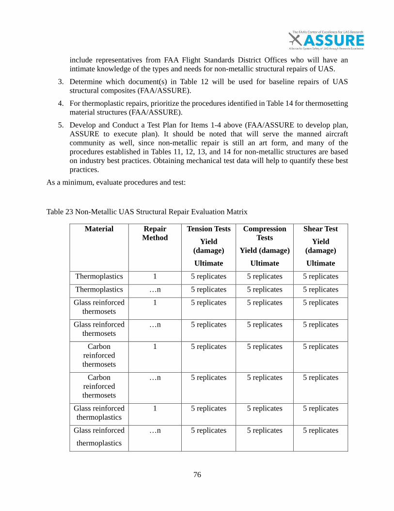
76
include representatives from FAA Flight Standards District Offices who will have an intimate knowledge of the types and needs for non-metallic structural repairs of UAS.
3. Determine which document(s) in Table 12 will be used for baseline repairs of UAS structural composites (FAA/ASSURE).
4. For thermoplastic repairs, prioritize the procedures identified in Table 14 for thermosetting material structures (FAA/ASSURE).
5. Develop and Conduct a Test Plan for Items 1-4 above (FAA/ASSURE to develop plan, ASSURE to execute plan). It should be noted that will serve the manned aircraft community as well, since non-metallic repair is still an art form, and many of the procedures established in Tables 11, 12, 13, and 14 for non-metallic structures are based on industry best practices. Obtaining mechanical test data will help to quantify these best practices.
As a minimum, evaluate procedures and test:
Table 23 Non-Metallic UAS Structural Repair Evaluation Matrix
Material Repair Method
Tension Tests Yield
(damage) Ultimate
Compression Tests
Yield (damage) Ultimate
Shear Test Yield
(damage) Ultimate
Thermoplastics 1 5 replicates 5 replicates 5 replicates
Thermoplastics …n 5 replicates 5 replicates 5 replicates
Glass reinforced thermosets
1 5 replicates 5 replicates 5 replicates
Glass reinforced thermosets
…n 5 replicates 5 replicates 5 replicates
Carbon reinforced thermosets
1 5 replicates 5 replicates 5 replicates
Carbon reinforced thermosets
…n 5 replicates 5 replicates 5 replicates
Glass reinforced thermoplastics
1 5 replicates 5 replicates 5 replicates
Glass reinforced thermoplastics
…n 5 replicates 5 replicates 5 replicates
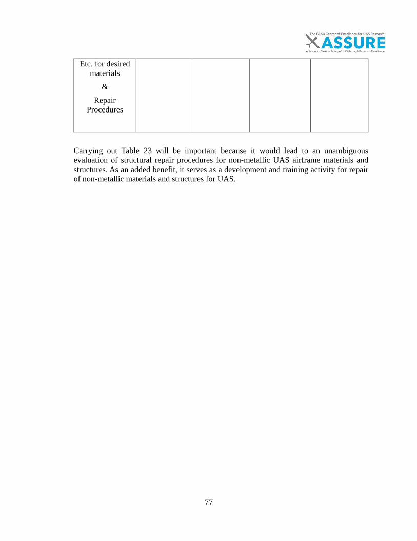
77
Etc. for desired materials
& Repair
Procedures
Carrying out Table 23 will be important because it would lead to an unambiguous evaluation of structural repair procedures for non-metallic UAS airframe materials and structures. As an added benefit, it serves as a development and training activity for repair of non-metallic materials and structures for UAS.

78
References

79
[1] H. Bendemra, P. Compston, and P. J. Crothers, "Optimisation study of tapered scarf and stepped-lap joints in composite repair patches," Composite Structures, vol. 130, pp. 1-8, 10/15/ 2015.
[2] C. N. Duong, "Design and validation of composite patch repairs to cracked metallic structures," Composites Part A: Applied Science and Manufacturing, vol. 40, no. 9, pp. 1320-1330, 9// 2009.
[3] K. B. Katnam, L. F. M. Da Silva, and T. M. Young, "Bonded repair of composite aircraft structures: A review of scientific challenges and opportunities," Progress in Aerospace Sciences, vol. 61, pp. 26-42, 8// 2013.
[4] T. Zhao, G. Palardy, I. F. Villegas, C. Rans, M. Martinez, and R. Benedictus, "Mechanical behaviour of thermoplastic composites spot-welded and mechanically fastened joints: A preliminary comparison," Composites Part B: Engineering, 2016.
[5] (2011). Development of Training/Qualification Programs for Composite Maintenance Technicians.
[6] (2010). AC20-107B, Composite Aircraft Structure w/chg1.
[7] (2013). Repairs and Alterations to Composite and Bonded Aircraft Structures.
[8] (2001). Static Strength Substantiation of Composite Airplane Strucutre; Policy Statement PS-ACE100-2001-006.
[9] Federal Aviation Administration. (2000). DOT/FAA/AR-00/46, Repair of Composite Laminates.
[10] (2004). DOT/FAA/AR-03/74, Bonded Repair of Aircraft Composite Sandwich Structures.
[11] Northrop-Grumman, "RQ-4 Global Hawk Fact Sheet," ed. Electronic, 2008, p. 5.
[12] R. A. Clothier, Palmer, Jennifer L., Walker, Rodney A., & Fulton, "Determination and Evaluation of UAV Safety Objectives," Australian Research Centre for Aerospace Automation, Queensland University of Technology,
Brisbane, Australia2006.
[13] (2010). AC21-47, Submittal of Data to an ACO, a DER or and ODA for a Major Repair or Major Alterations.
[14] (1998). AC43-9C, Maintenance Records.
[15] (2009). Risk Management Handbook (FAA-H-8083-2).
[16] (2017). Major Repair and Alteration Form 337 (OMB 2120-0020).
[17] (2011). AC23.1309-1E, System Safety Analysis for Part 23 Airplanes.

80
[18] (2016). Major Repair and Alteration Data Approval.
[19] R. A. Clothier, Palmer, Jennifer L., Walker, Rodney A., & Fulton, and N. L., "Definition of airworthiness categories for civil Unmanned Aircraft Systems (UAS)," presented at the In: 27th International Congress of the Aeronautical Sciences, Acropolis Conference Centre, Nice, 2010.
[20] F. M. Grimsely, "Equivalent Safety Analysis using Casualty Expectation Approach," presented at the AIAA 3rd "Unamnned Unlimited" Technical Conference, Workshop and Exhibit, Chicago, Illinois, 2004.
[21] M. Huerta. (2017, January 21st, 2017). Drones: A Story of Revolution and Evolution [Speech]. Available: https://www.faa.gov/news/speeches/news_story.cfm?newsId=21316
[22] F. A. R. Comittee, "Micro Unmanned Aircraft Systems Aviation Rulemaking Comittee (ARC)," 2016.
[23] (2016). Form 7711-1 (7-74), Form 7711-1 UAS COA, Blanket COA for any Operations Issued a Valid Section 333 Grant of Exemption.
[24] M. A. Caminero, M. Lopez-Pedrosa, C. Pinna, and C. Soutis, "Damage monitoring and analysis of composite laminates with an open hole and adhesively bonded repairs using digital image correlation," Composites Part B: Engineering, vol. 53, pp. 76-91, 10// 2013.
[25] J. Renard and A. Thionnet, "Damage in composites: From physical mechanisms to modelling," Composites Science and Technology, vol. 66, no. 5, pp. 642-646, 5// 2006.
[26] M. V. Hosur, M. Adya, J. Alexander, S. Jeelani, U. Vaidya, and A. Mayer, "Studies on Impact Damage Resistance of Affordable Stitched Woven Carbon/Epoxy Composite Laminates," Journal of Reinforced Plastics and Composites, vol. 22, no. 10, pp. 927-952, 2003/07/01 2003.
[27] Federal Aviation Administration. (2002). DOT/FAA/AR-02/80, Impact Damage Characterization and Damage Tolerance of Composite Sandwich Airframe Structures - Phase II.
[28] F. Oakes, "Boeing Composite Airframe Damage Tolerance and Service Experience," Presentation.
[29] Standard Practice for Operational Risk Assesment of Small Unmanned Aircraft Systems (sUAS), 2016.
[30] (2000). AC61-89E, Pilot Certificates: Aircraft Type Rating.
[31] S. G. Reid, "Perception and communication of risk, and the importance of dependability," Structural Safety, vol. 21, no. 4, pp. 373-384, 12// 1999.

81
[32] (2015). R44192, Unmanned Aircraft Systems (UAS): Commercial Outlook for a New Industry.
[33] "Micro Unmanned Aircraft Systems Avaition Rulemaking Committee (ARC)," APril 1st, 2016 2016.
[34] (2016). AC 107-2, Small Unmanned Aircraft Systems, AC 107-2.
[35] K. M. Thompson, R. F. Rabouw, and R. M. Cooke, "The Risk of Groundling Fatalities from Unintentional Airplane Crashes," Risk Analysis, vol. 21, no. 6, pp. 1025-1038, 2001.
[36] (2003). Columbia Accident Investigation Board.
[37] D. Inc., "Inspire 1 Maintenance Manual V1.0 2015.2," in Electronic Copy, ed, 2015, p. 2.
[38] Standard Specification for Design and Construction of a Small Unmanned Aircraft System (sUAS), 2014.
[39] M. D. Banea and L. F. M. da Silva, "Adhesively bonded joints in composite materials: An overview," Proceedings of the Institution of Mechanical Engineers, Part L: Journal of Materials Design and Applications, vol. 223, no. 1, pp. 1-18, January 1, 2009 2009.
[40] A. Yousefpour, M. Hojjati, and J.-P. Immarigeon, "Fusion Bonding/Welding of Thermoplastic Composites," Journal of Thermoplastic Composite Materials, vol. 17, no. 4, pp. 303-341, 2004.
[41] (2002). Standard 321-02, Common Risk Criteria for National Test Ranges: Inert Debris. Available: http://jcs.mil/RCC
[42] (2000). Risk -based Explosives Safety Analysis Technical Paper No. 14.
[43] C. Soutis, "Fibre reinforced composites in aircraft construction," Progress in Aerospace Sciences, vol. 41, no. 2, pp. 143-151, 2// 2005.
[44] D. K. Scott Kesselman, "The First 1,000 Commercial UAS Exemptions," Association for Unmanned Vehicle Systems International, Electronic2017.
[45] R. Austin, Unmanned Aircraft Systems UAVS Design, Development, and Deployment, 1 ed. Wiltshire, UK: John Wiley & Sons Ltd, 2010, p. 365.
[46] SenseFly eBee "Technical Specifications," in Electronic, Sensefly. https://www.sensefly.com/drones/ebee.html. Accessed July 10, 2017
[47] K. Barnhart, "A.5 Maintenance, Modification, Repair, Inspection, Training, and Certification Considerations," Kansas State University2016.
[48] Yamaha. (2017, 2/12/2017). Yamaha R-Max Specifications. Available: http://rmax.yamaha-motor.com.au/
82
[49] U. S. Army. (2017, 2/15/2017). 15E Unmanned Aircraft Systems Repairers Study UAS Maintenance Support on FH. Available: https://www.army.mil/article/88843/15E_unmanned_aircraft_systems_repairers_study_UAS_maintenance_support_on_FH
[50] (2008). FAA-G-8032-3A, Aviation Maintenance Technician- General, Airframe, and Powerplant Knowledge Test Guide.
[51] I. DYS. (2017). Replacement Carbon Blades. Available: http://www.dys.hk/ProductShow.asp?ID=101
[52] (2012). AC21-12C, Application for U.S. Airworthiness Certificate, FAA Form 8130-6.
[53] A. Baker, "Special Issue on Repair," Composites Part A: Applied Science and Manufacturing, vol. 40, no. 9, p. 1319, 9// 2009.
[54] A. A. Baker, R. J. Chester, G. R. Hugo, and T. C. Radtke, "Scarf repairs to highly strained graphite/epoxy structure," International Journal of Adhesion and Adhesives, vol. 19, no. 2–3, pp. 161-171, 4// 1999.
[55] DJI. (2017, 1/25/2017). DJI Repair Service Pricing. Available: https://repair.dji.com/en/SelfRepair/PriceQuery
[56] (2010). AC21-45, Commercial Parts.
[57] S. Denning. (2013, 01/23/2017). What Went Wrong at Boeing. Available: http://www.forbes.com/sites/stevedenning/2013/01/21/what-went-wrong-at-boeing/#2cdf09635aad
[58] C. S. R. Team, "Boeing 787 Design, Certification, and Manufacturing Systems Review," Boeing2014.
[59] S.-H. Ahn and G. S. Springer, "Repair of Composite Laminates-I: Test Results," Journal of Composite Materials, vol. 32, no. 11, pp. 1036-1074, 1998/06/01 1998.
[60] SAE, Composites Materials Handbook, CMH-17. 2013.
[61] V. K. Dalamagkidis K., Piegl Les A., On Integrating Unmanned Aircraft Systems into the National Airspace System 2nd ed. Berlin, Germany: Springer Science & Business Media, 2011.
[62] D. Stavrov and H. E. N. Bersee, "Resistance welding of thermoplastic composites-an overview," Composites Part A: Applied Science and Manufacturing, vol. 36, no. 1, pp. 39-54, 1// 2005.
[63] S. M. Welder, H. J. Lause, and R. Fountain, "Structural repair systems for thermoplastic composites," Materials & Design, vol. 7, no. 3, pp. 147-149, 1986/05/01 1986.

83
[64] (1998). Acceptable Methods, Techniques, and Practices - Aircraft Inspection and Repair.
[65] A. Baker, S. Dutton, and D. Kelly, "Composite Materials for Aircraft Structures (2nd Edition)," ed: American Institute of Aeronautics and Astronautics.
[66] A. Baker, N. Rajic, and C. Davis, "Towards a practical structural health monitoring technology for patched cracks in aircraft structure," Composites Part A: Applied Science and Manufacturing, vol. 40, no. 9, pp. 1340-1352, 9// 2009.
[67] R. D. S. G. Campilho, M. F. S. F. de Moura, and J. J. M. S. Domingues, "Modelling single and double-lap repairs on composite materials," Composites Science and Technology, vol. 65, no. 13, pp. 1948-1958, 10// 2005.
[68] R. D. S. G. Campilho, M. F. S. F. de Moura, and J. J. M. S. Domingues, "Using a cohesive damage model to predict the tensile behaviour of CFRP single-strap repairs," International Journal of Solids and Structures, vol. 45, no. 5, pp. 1497-1512, 3/1/ 2008.
[69] R. D. S. G. Campilho, M. F. S. F. de Moura, and J. J. M. S. Domingues, "Numerical prediction on the tensile residual strength of repaired CFRP under different geometric changes," International Journal of Adhesion and Adhesives, vol. 29, no. 2, pp. 195-205, 3// 2009.
[70] R. B. Heslehurst, "Analysis and modelling of damage and repair of composite materials in aerospace," in Numerical Analysis and Modelling of Composite Materials, J. W. Bull, Ed. Dordrecht: Springer Netherlands, 1996, pp. 27-59.
[71] D. Paris, "A Study of Failure Criteria of Fibrous Composite Materials," George Washinton University, Hampton, VaNASA/CR-2001-210661, 2001.
[72] R. A. Odi and C. M. Friend, "A Comparative Study of Finite Element Models for the Bonded Repair of Composite Structures," Journal of Reinforced Plastics and Composites, vol. 21, no. 4, pp. 311-332, 2002/03/01 2002.
[73] L. J. Hart-Smith, "Bonded-bolted composite joints," Journal of Aircraft, vol. 22, no. 11, pp. 993-1000, 1985/11/01 1985.
[74] X.-J. Gong, P. Cheng, S. Aivazzadeh, and X. Xiao, "Design and optimization of bonded patch repairs of laminated composite structures," Composite Structures, vol. 123, pp. 292-300, 5// 2015.
[75] C. H. Wang and A. J. Gunnion, "Optimum shapes of scarf repairs," Composites Part A: Applied Science and Manufacturing, vol. 40, no. 9, pp. 1407-1418, 9// 2009.
[76] A. Baker, A. J. Gunnion, and J. Wang, "On the Certification of Bonded Repairs to Primary Composite Aircraft Components," The Journal of Adhesion, vol. 91, no. 1-2, pp. 4-38, 2015/01/02 2015.
84
[77] A. Benatar, "Ultrasonic welding of advanced thermoplastic composites," Mechanical Engineering, Massachusetts Institute of Technology. Dept. of Mechanical Engineering, Massachusetts Institute of Technology, Massachusetts Institute of Technology, 1987.
[78] G. Reyes and U. Sharma, "Modeling and damage repair of woven thermoplastic composites subjected to low velocity impact," Composite Structures, vol. 92, no. 2, pp. 523-531, 1// 2010.
[79] S. Beland, High Peformance Thermoplastics Resins and Their Composites. William Andrew, 1990.
[80] E. C. Eveno and J. John W. Gillespie, "Resistance Welding of Graphite Polyetheretherketone Composites: An Experimental Investigation," Journal of Thermoplastic Composite Materials, vol. 1, no. 4, pp. 322-338, 1988.
[81] B. Corporation, "Advantages of Welded Nylon for Powertrain Applications: Linear Vibration, Orbital Vibration and Hot Plate Welding Technologies," Electronic2003, Available: http://www8.basf.us//PLASTICSWEB/displayanyfile?id=0901a5e18000487b.
[82] H. Potente, M. Uebbing, and E. Lewandowski, "The Vibration Welding of Polyamide 66," Journal of Thermoplastic Composite Materials, vol. 6, no. 1, pp. 2-17, 1993/01/01 1993.
[83] Polyvance Inc., "The Book of Plastic Repair," Polvance, Ed., 10 ed. Electronic: Polyvance Inc., 2017, p. 20.
[84] T. J. Chapman, J. W. Gillespie, R. B. Pipes, J. A. E. Manson, and J. C. Seferis, "Prediction of Process-Induced Residual Stresses in Thermoplastic Composites," Journal of Composite Materials, vol. 24, no. 6, pp. 616-643, 1990/06/01 1990.
[85] G. Marsh, "Reinforced thermoplastics, the next wave?," Reinforced Plastics, vol. 58, no. 4, pp. 24-28, 7// 2014.
[86] C. Soutis, "Carbon fiber reinforced plastics in aircraft construction," Materials Science and Engineering: A, vol. 412, no. 1–2, pp. 171-176, 12/5/ 2005.
[87] A. R. Rennie, "Thermoplastics and Thermosets," in Mechanical Properties and Testing of Polymers: An A–Z Reference, G. M. Swallowe, Ed. Dordrecht: Springer Netherlands, 1999, pp. 248-248.
[88] S. Ebnesajjad, "Chapter 10 - Effects of Additives on Surface Treatment of Plastics," in Surface Treatment of Materials for Adhesive Bonding (Second Edition)Oxford: William Andrew Publishing, 2014, pp. 271-281.
[89] D. A. Cole and L. Zhang, "10 - Surface Analysis Methods for Contaminant Identification A2 - Kohli, Rajiv," in Developments in Surface Contamination and Cleaning, K. L. Mittal, Ed. Norwich, NY: William Andrew Publishing, 2008, pp. 585-652.
85
[90] M. Chawla. (2017, 01/23/2017). How Clean if Clean? Defining Acceptable Cleanliness Levels. Available: http://www.photoemission.com/techpapers/How_Clean_is_Clean_TMS05PPR.pdf
[91] Standard Test Method for Hydrophobic Surface Films by the Water-Break Test, 2013.
[92] Standard Test Method for Measuring the Damage Resistance of a Fiber-Reinforced Polymer Matrix Composite to a Drop-Weight Impact Event, 2015.
[93] W. J. Cantwell and J. Morton, "The impact resistance of composite materials — a review," Composites, vol. 22, no. 5, pp. 347-362, 1991/09/01 1991.
[94] F.-K. Chang, H. Y. Choi, and S.-T. Jeng, "Study on impact damage in laminated composites," Mechanics of Materials, vol. 10, no. 1, pp. 83-95, 1990/11/30 1990.
[95] J. S. V. U. Hosur M., Nwosu S., Kelkar A., "Survivability of Affordable Aircraft Composite Structures Volume 1: Overview and Ballistic Impact Testing of Afforable Woven Carbon/Epoxy Composites," Tuskegee University and The University of Alabama Birmingham, Final Report 2004, vol. 1.
[96] A. Malhotra and F. J. Guild, "Impact Damage to Composite Laminates: Effect of Impact Location," Applied Composite Materials, journal article vol. 21, no. 1, pp. 165-177, 2014.
[97] D. Kazmer, "31 - Design of Plastic Parts A2 - Kutz, Myer," in Applied Plastics Engineering HandbookOxford: William Andrew Publishing, 2011, pp. 535-551.
[98] U. Polimeno and M. Meo, "Detecting barely visible impact damage detection on aircraft composites structures," Composite Structures, vol. 91, no. 4, pp. 398-402, 12// 2009.
[99] M. A. Caminero, S. Pavlopoulou, M. Lopez-Pedrosa, B. G. Nicolaisson, C. Pinna, and C. Soutis, "Analysis of adhesively bonded repairs in composites: Damage detection and prognosis," Composite Structures, vol. 95, pp. 500-517, 1// 2013.
[100] F. Awaja, S. Zhang, M. Tripathi, A. Nikiforov, and N. Pugno, "Cracks, microcracks and fracture in polymer structures: Formation, detection, autonomic repair," Progress in Materials Science, vol. 83, pp. 536-573, 10// 2016.
[101] F. Collombet et al., "10 - Repairing composites A2 - Boisse, Philippe," in Advances in Composites Manufacturing and Process Design: Woodhead Publishing, 2015, pp. 197-227.
[102] (2007). AC 120-93, Damage Tolerance Inspections for Repairs and Alterations, AC 120-93.
[103] T. D. Hartner J., "Life Analysis Development and Verification Damage Tolerance Application of Mutiple Through Cracks in Plates with and Without Holes," Analytical
86
Mechanics Branch (AFRL/VASM) and Eagle Aeronautics, Final Report AFRL-VA-WP-TR-2004-3112, 2004.
[104] T. Jollivet, C. Peyrac, and F. Lefebvre, "Damage of Composite Materials," Procedia Engineering, vol. 66, pp. 746-758, // 2013.
[105] (2014). 65-31B, Training, Qualification, and Certification of Nondestructive Inspection Personnel.
[106] (1997). AC43-204, Visual Inspection for Aircraft.
[107] D. K. Hsu, "Nondestructive Inspection of Composite Structures: Methods and Practice," presented at the 17th World Conference on Nondestructive Testing, Shanghai, China, 25-28 Oct 2008, 2008.
[108] (2012). AC145-10, Repair Station Training Program, AC145-10.
[109] Cawley, "The Mechanics of the Coin-Tap Method of Non-Destructive Testing," Journal of Sound and Virbration, vol. 122, no. 2, pp. 299-316, 1988.
[110] S. Gholizadeh, "A review of non-destructive testing methods of composite materials," Procedia Structural Integrity, vol. 1, pp. 50-57, // 2016.
[111] DJI Inc., "Inspire 1 Maintenance Manual V1.0 2015.2," in Electronic Copy, ed, 2015, p. 2.
[112] S. Yamashita, T. Sonehara, J. Takahashi, K. Kawabe, and T. Murakami, "Effect of thin-ply on damage behaviour of continuous and discontinuous carbon fibre reinforced thermoplastics subjected to simulated lightning strike," Composites Part A: Applied Science and Manufacturing, vol. 95, pp. 132-140, 4// 2017.
[113] Federal Aviation Administration. (2016). DOT/FAA/TC-15/4, A Quantitative Assesment of Advanced Nondestructive Inspection Techniques for Detecting Flaws in Composite Laminate Aircraft Structures.
[114] T. N. Ritchey, "Development of Failure Criteria and Experimental Testing For Composite Adhesively Bonded Scarf Repairs Utilizing Structural Paste Adhesives," Mechanical Engineering Masters of Science, Mechanical Engineering, Montana State University, 2014.
[115] DJI. (2017, 1/23/2017). DJI Inspire 1. Available: http://www.dji.com/inspire-1/info#downloads
[116] "Raven RQ-11A/B," in Electronic vol. Ver: 02062017, AeroVironment, Ed., ed. Online: AeroVironment, 2017, p. 1.
[117] C. Wilke, "ScanEagle Overview," Boeing, Ed., ed, 2007.

87
[118] (2008). AC43.13-2B, Acceptable Methods, Techniques, and Practices - Aircraft Alteration.
[119] (1991). F33615-87-C-5236, Paint Removal From Composites and Protective Coating Development.
[120] C. J. Tautscher, "Contamination Effects on Electronic Products," Microelectronics Reliability, vol. 32, no. 10, p. 1491, 1992/10/01 1992.
[121] M. S. Won and C. K. H. Dharan, "Drilling of Aramid and Carbon Fiber Polymer Composites," Journal of Manufacturing Science and Engineering, vol. 124, no. 4, pp. 778-783, 2002.
[122] (2005). Composite Materials Handbook.
[123] C.-H. Shen and G. S. Springer, "Moisture Absorption and Desorption of Composite Materials," Journal of Composite Materials, vol. 10, no. 1, pp. 2-20, 1976.
[124] L. J. Hart-Smith and E. Troiani, "Backing-Out Composite Lamina Strengths from Cross-Ply Testing," in Reference Module in Materials Science and Materials Engineering: Elsevier, 2017.
[125] Standard Test Method for Ignition Loss of Cured Reinforced Resins, 2011.
[126] (2005). AC145-10, Repair Station Training Program.
[127] T. S. Jahnke, "Nylon Plastics Handbook Edited by Melvin I. Kohan (MIK Associates). Hanser: Cincinnati, OH. 1995. xii + 631 pp. $198.00. ISBN 1-56990-189-9," Journal of the American Chemical Society, vol. 118, no. 34, pp. 8186-8186, 1996/01/01 1996.
[128] P. Inc., "The Book of Plastic Repair," Polvance, Ed., 10 ed. Electronic: Polyvance Inc., 2017, p. 20.
[129] H. Composites, "Composite Repair," Electronic1999, Available: http://www.hexcel.com/resources/datasheets/brochure-data-sheets/composite_repair.pdf.
[130] Standard Practice for Preparation of Surfaces of Plastics Prior to Adhesive Bonding, 2011.
[131] Standard Test for Moisture Absorbtion Properties and Equilibrium Conditioning of Polymer Matrix Composite Materials, 2014.
[132] (2006). Order 8110.37E, Designated Engineering Representative (DER) Handbook.
[133] (2016). AC39-10, Alternative Methods of Compliance.
[134] (2017). Statement of Compliance with Airworthiness Standards.

88
[135] K. A. Latorella and P. V. Prabhu, "A review of human error in aviation maintenance and inspection," International Journal of Industrial Ergonomics, vol. 26, no. 2, pp. 133-161, 8// 2000.
[136] K. M. Cantor and P. Watts, "12 - Plastics Processing A2 - Kutz, Myer," in Applied Plastics Engineering HandbookOxford: William Andrew Publishing, 2011, pp. 195-203.
[137] D. J. Quesnel, D. S. Rimai, and D. M. Schaefer, "7 - Aspects of Particle Adhesion and Removal A2 - Kohli, Rajiv," in Developments in Surface Contamination and Cleaning, K. L. Mittal, Ed. Norwich, NY: William Andrew Publishing, 2008, pp. 475-501.
[138] J. B. Durkee, "15 - Cleaning with Solvents A2 - Kohli, Rajiv," in Developments in Surface Contamination and Cleaning, K. L. Mittal, Ed. Norwich, NY: William Andrew Publishing, 2008, pp. 759-871.
[139] S. Ebnesajjad, "Chapter 1 - Introduction to Surface Preparation," in Surface Treatment of Materials for Adhesive Bonding (Second Edition)Oxford: William Andrew Publishing, 2014, pp. 3-6.
[140] Standard Test Method for Tensile Properties of Polymer Matrix Composite Materials, 2014.
[141] Standard Terminology of Adhesives, 2015.
[142] B. O. Bateup, "Surface chemistry and adhesion," International Journal of Adhesion and Adhesives, vol. 1, no. 5, pp. 233-239, 1981/07/01 1981.
[143] R. Hunter, J. Möller, A. Vizán, J. Pérez, J. Molina, and J. Leyrer, "Experimental study of the effect of microspheres and milled glass in the adhesive on the mechanical adhesion of single lap joints," The Journal of Adhesion, pp. 1-17, 2016.
[144] L. Dorworth, Gardiner, G. , Mellema, G.,, Essentials of Advanced Composite Fabrication & Repair. Newcastle, Wa: Aviation Supplies & Academics, Inc., 2009.
[145] (2015). AC00-56B, Voluntary Industry Distributor Accreditation Program.
[146] A. Dutta and M. E. Ryan, "Effect of fillers on kinetics of epoxy cure," Journal of Applied Polymer Science, vol. 24, no. 3, pp. 635-649, 1979.
[147] A. Witkowski, A. A. Stec, and T. R. Hull, "Thermal Decomposition of Polymeric Materials," in SFPE Handbook of Fire Protection Engineering, M. J. Hurley et al., Eds. New York, NY: Springer New York, 2016, pp. 167-254.
[148] (1983). AC65-24, Certification of a Repairman.
[149] J. R. Tarpani, R. B. Canto, R. G. M. Saracura, C. Ibarra-Castanedo, and X. P. V. Maldague, "Compression After Impact and Fatigue of Reconsolidated Fiber-reinforced
89
Thermoplastic Matrix Solid Composite Laminate," Procedia Materials Science, vol. 3, pp. 485-492, // 2014.
[150] S. Barré and M. L. Benzeggagh, "On the use of acoustic emission to investigate damage mechanisms in glass-fibre-reinforced polypropylene," Composites Science and Technology, vol. 52, no. 3, pp. 369-376, // 1994.
[151] C. M. Edwards and E. L. d'Hooghe, "Fiber-reinforced composite encased in a thermoplastic and method of making same," ed: Google Patents, 2002.
[152] (2014). FAA Aerospace Forecast Fiscal Years 2015-2035.
[153] U. C. International, "Approval Process for Frames and Forks," ed. Aigle, Switzerland, 2011, p. 21.

90
Appendices

91
APPENDIX A: ASSURE PROJECT TASKS, TIMEFRAME, AND COST STRUCTURE
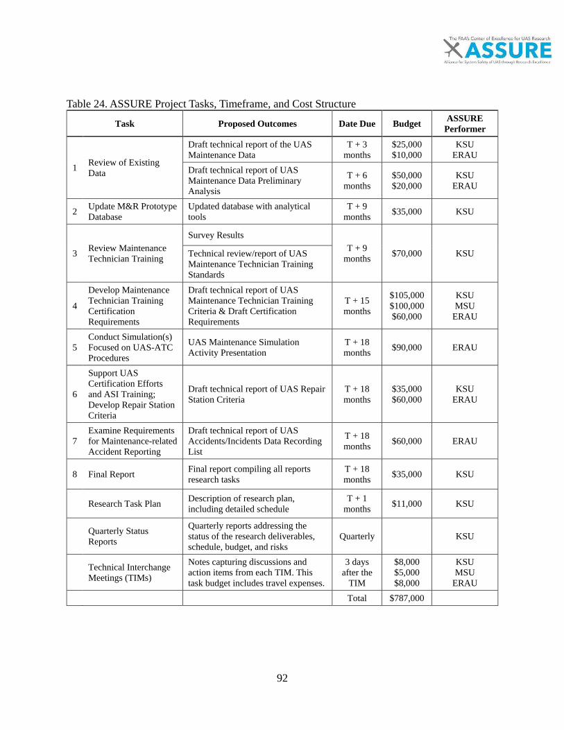
92
Table 24. ASSURE Project Tasks, Timeframe, and Cost Structure
Task Proposed Outcomes Date Due Budget ASSURE Performer
1 Review of ExistingData
Draft technical report of the UAS Maintenance Data
T + 3 months
$25,000 $10,000
KSU ERAU
Draft technical report of UAS Maintenance Data Preliminary Analysis
T + 6 months
$50,000 $20,000
KSU ERAU
2 Update M&R PrototypeDatabase
Updated database with analytical tools
T + 9 months $35,000 KSU
3 Review MaintenanceTechnician Training
Survey Results T + 9
months $70,000 KSU Technical review/report of UAS Maintenance Technician Training Standards
4
Develop Maintenance Technician Training Certification Requirements
Draft technical report of UAS Maintenance Technician Training Criteria & Draft Certification Requirements
T + 15 months
$105,000 $100,000 $60,000
KSU MSU
ERAU
5 Conduct Simulation(s) Focused on UAS-ATC Procedures
UAS Maintenance Simulation Activity Presentation
T + 18 months $90,000 ERAU
6
Support UAS Certification Efforts and ASI Training; Develop Repair Station Criteria
Draft technical report of UAS Repair Station Criteria
T + 18 months
$35,000 $60,000
KSU ERAU
7 Examine Requirements for Maintenance-related Accident Reporting
Draft technical report of UAS Accidents/Incidents Data Recording List
T + 18 months $60,000 ERAU
8 Final Report Final report compiling all reports research tasks
T + 18 months $35,000 KSU
Research Task Plan Description of research plan, including detailed schedule
T + 1 months $11,000 KSU
Quarterly Status Reports
Quarterly reports addressing the status of the research deliverables, schedule, budget, and risks
Quarterly KSU
Technical Interchange Meetings (TIMs)
Notes capturing discussions and action items from each TIM. This task budget includes travel expenses.
3 days after the
TIM
$8,000 $5,000 $8,000
KSU MSU
ERAU Total $787,000

93
APPENDIX B: A SIMILAR REPAIR SCHEME

94
Appendix B includes relevant figures of the repair process on systems within this scope. Additional test data and figures of the repair process have been included here from various sources. Bicycle frames are shown here. These bicycle frames are high performance carbon composite systems and represent an excellent cross section of a number of features also found in composite structures found in UAS systems. Minor damage is shown in Figure 40 and major damage is shown in Figure 41. The repair procedure for these systems followed the best practices and a full repair performed by Carbon Bike Repair NZ is shown in Figures 43-45. Additionally, the Union Cycliste International (UCI) has developed methods for a simple testing protocol of new frame designs. These design requirements improve the overall safety and design of the carbon systems [153]. These protocols were not studied within this paper, but represent an implementation of minimum structural testing protocols to maintain safety of a potentially dangerous system.
Figure 43. Minor Damage of Thin Carbon Epoxy Laminate
Figure 44. Substantial Composite Damage to a Carbon Composite Tube
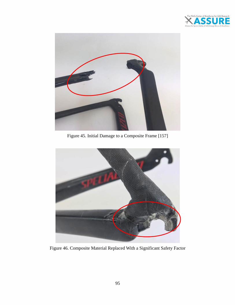
95
Figure 45. Initial Damage to a Composite Frame [157]
Figure 46. Composite Material Replaced With a Significant Safety Factor

96
Figure 47. Composite Finishing to Improve Contour
Figure 48. Finishing Paint to Protect Surface

97
APPENDIX C: EXAMPLE LIST OF SECTION 333 REPAIR EXEMPTIONS

98
The intent of this section is to show the current list of 333 exemptions in the national airspace for small systems from manufacturer and the location. The predominant manufacturer is DJI Inc. followed by a number of other systems. These system are outlined in Table 24 below. The intent is not to provide a comprehensive list of exemptions as has been done by the ASSURE Air to Air and Air to Ground Collision teams, rather to provide examples of what platforms may be exempt from FAA repair criteria.

99
Table 25. UAS Section 333 Exemptions Between August 2014 and April 2015 Manufacturer/Date of Exemption Exempted Company Field Platform/Model of UAV
DJI
4/3/2015 Videe This! Inc. dba Yeah Drones Photo/Film DJI S900 and DJI Phantom 2
4/3/2015 Shotwell Media, LLC Photo/Film DJI S1000, DJI S900, DJI Inspire 1, and DJI Phantom 2
4/3/2015 CineDrones, LLC Photo/Film DJI S900, DJI S1000, and DJI Inspire 1
4/3/2015 Perfect View Aerial Media, LLC Inspections - Electric DJI S–1000
4/3/2015 Danis Building Construction Company
Inspections - Construction DJI Phantom Vision 2+
4/3/2015 Nixon Engineering Solutions, LLC Inspections - Oil&Gas DJI S800 EVO
4/3/2015 AIG PC Global Services, Inc. R&D
Hawkeye Lancaster MK-III, IRIS+, Phantom 2 Vision, and senseFly eBee
4/3/2015 Monterey Drone Photo/Film - Real Estate DJI Phantom 2
Manufacturer/Date of Exemption Exempted Company Field Platform/Model of UAV
4/3/2015 Hawaii AirVision, LLC Photo/Film DJI S1000 4/3/2015 ETAK Systems, Inc. Inspection DJI Phantom 2 Vision
4/3/2015 First Flight Photography, LLC Photo/Film DJI Phantom 2 Vision Plus and the DJI Spreading Wings S1000
4/3/2015 Upward Aerial Photo/Film T600 DJI Inspire 1 4/3/2015 SkyPhilly, Inc. General Use DJI S-900
4/3/2015 Drone Fleet & Aerospace Management, Inc. Inspections
DJI S1000, DJI Phantom 2, and Drone- Fleet Carbon Fiber V5
3/26/2015 Aerius Flight, LLC Aerial survey and photography
Walkera Scout X4 and DJI S900
3/24/2015 Montico, Inc. Inspections DJI Phantom 2 Vision+

100
3/24/2015 NextEra Energy, Inc. Inspections DJI Phantom 2 Vision Plus, DJI Inspire I (T600), and DJI S900
3/24/2015 Oceaneering International, Inc. Inspections / Surveys
Wookong DJI S800 and Aeronavics X4 Titanium
Manufacturer/Date of Exemption Exempted Company Field Platform/Model of UAV
3/24/2015 Steven Zeets R&D 8 Total
3/20/2015 Mike Johnson Inspections DJI Phantom 2 Vision +
3/20/2015 Saratoga Aerial Photo and Video Photo / Video DJI PhantomVision 2+
3/20/2015 Aerial Production Services, Inc. Photo/Video + Inspections
DJI Phantom 2
3/11/2015 Build Imagery, LLC
Photo/Video + Inspections
3d Robotics Iris+ and the DJI Inspire 1
3/6/2015 FalconSkyCam Photo/Video - Real Estate DJI Phantom 2
3/3/2015 Singer's Creations Photo/Video - Real Estate DJI Phantom 2 Vision +
2/27/2015 Video Solutions LLC Photo/Video DJI Phantom 2 Vision+
2/24/2015 Commonwealth Edison Company Inspections DJI Innovations S900
2/13/2015 Capital Aerial Video, LLC Photo/Video DJI Model F550 UAS
2/3/2015 Helinet Aviation Services, LLC Photo/Video Gryphon Dynamics X8 and DJI S1000
Manufacturer/Date of Exemption Exempted Company Field Platform/Model of UAV
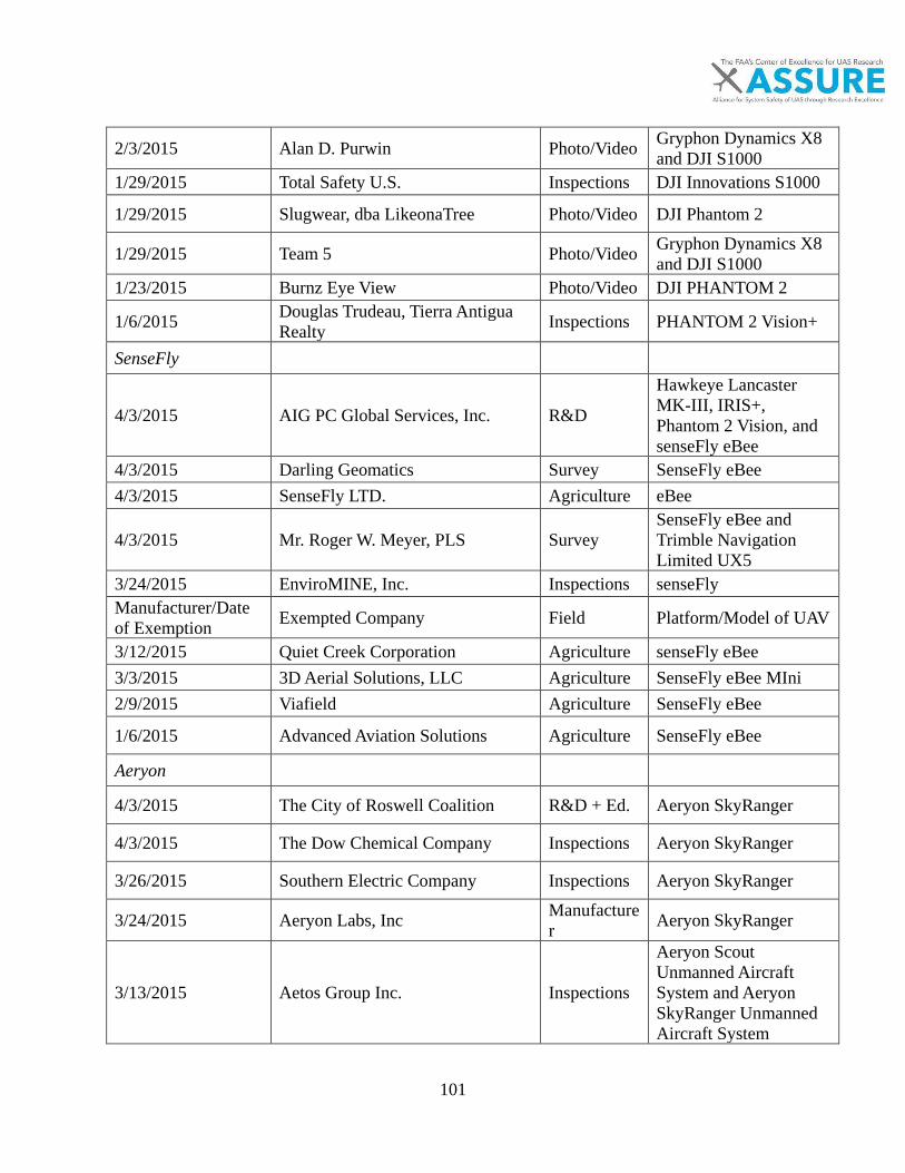
101
2/3/2015 Alan D. Purwin Photo/Video Gryphon Dynamics X8 and DJI S1000
1/29/2015 Total Safety U.S. Inspections DJI Innovations S1000
1/29/2015 Slugwear, dba LikeonaTree Photo/Video DJI Phantom 2
1/29/2015 Team 5 Photo/Video Gryphon Dynamics X8 and DJI S1000
1/23/2015 Burnz Eye View Photo/Video DJI PHANTOM 2
1/6/2015 Douglas Trudeau, Tierra Antigua Realty Inspections PHANTOM 2 Vision+
SenseFly
4/3/2015 AIG PC Global Services, Inc. R&D
Hawkeye Lancaster MK-III, IRIS+, Phantom 2 Vision, and senseFly eBee
4/3/2015 Darling Geomatics Survey SenseFly eBee 4/3/2015 SenseFly LTD. Agriculture eBee
4/3/2015 Mr. Roger W. Meyer, PLS Survey SenseFly eBee and Trimble Navigation Limited UX5
3/24/2015 EnviroMINE, Inc. Inspections senseFly Manufacturer/Date of Exemption Exempted Company Field Platform/Model of UAV
3/12/2015 Quiet Creek Corporation Agriculture senseFly eBee 3/3/2015 3D Aerial Solutions, LLC Agriculture SenseFly eBee MIni 2/9/2015 Viafield Agriculture SenseFly eBee
1/6/2015 Advanced Aviation Solutions Agriculture SenseFly eBee
Aeryon
4/3/2015 The City of Roswell Coalition R&D + Ed. Aeryon SkyRanger
4/3/2015 The Dow Chemical Company Inspections Aeryon SkyRanger
3/26/2015 Southern Electric Company Inspections Aeryon SkyRanger
3/24/2015 Aeryon Labs, Inc Manufacture r Aeryon SkyRanger
3/13/2015 Aetos Group Inc. Inspections
Aeryon Scout Unmanned Aircraft System and Aeryon SkyRanger Unmanned Aircraft System
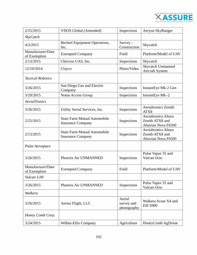
102
2/25/2015 VDOS Global (Amended) Inspections Aeryon SkyRanger SkyCatch
4/3/2015 Bechtel Equipment Operations, Inc.
Survey - Construction Skycatch
Manufacturer/Date of Exemption Exempted Company Field Platform/Model of UAV
2/13/2015 Chevron UAS, Inc. Inspections Skycatch
12/10/2014 Clayco Photo/Video Skycatch Unmanned Aircraft System
Tactical Robotics
3/26/2015 San Diego Gas and Electric Company Inspections InstantEye Mk-2 Gen
3/20/2015 Notus Access Group Inspections InstantEye Mk–2 AerialTronics
3/26/2015 Utility Aerial Services, Inc. Inspections Aerialtronics Zenith ATX8
2/25/2015 State Farm Mutual Automobile Insurance Company Inspections
Aerialtronics Altura Zenith ATX8 and Altavian Nova F6500
2/13/2015 State Farm Mutual Automobile Insurance Company Inspections
Aerialtronics Altura Zenith ATX8 and Altavian Nova F6500
Pulse Aerospace
3/26/2015 Phoenix Air UNMANNED Inspections Pulse Vapor 35 and Vulcan Octo
Manufacturer/Date of Exemption Exempted Company Field Platform/Model of UAV
Vulcan UAV
3/26/2015 Phoenix Air UNMANNED Inspections Pulse Vapor 35 and Vulcan Octo
Walkera
3/26/2015 Aerius Flight, LLC Aerial survey and photography
Walkera Scout X4 and DJI S900
Honey Comb Corp.
3/24/2015 Wilbur-Ellis Company Agriculture HoneyComb AgDrone

103
C-Astral
3/24/2015 Vision Services Group, LLC Agriculture
C-Astral: Bramor gEO, Volt Aerial Robotics: Octane, and Aeromao: AeroMapper 300.
Volt Aerial Robotics
3/24/2015 Vision Services Group, LLC Agriculture
C-Astral: Bramor gEO, Volt Aerial Robotics: Octane, and Aeromao: AeroMapper 300.
Aeromao
Manufacturer/Date of Exemption Exempted Company Field Platform/Model of UAV
3/24/2015 Vision Services Group, LLC Agriculture
C-Astral: Bramor gEO, Volt Aerial Robotics: Octane, and Aeromao: AeroMapper 300.
Aeronavics
3/24/2015 Oceaneering International, Inc. Inspections / Surveys
Wookong DJI S800 and Aeronavics X4 Titanium
Industrial Aerobotics
3/24/2015 Industrial Aerobotics, LLC Inspections / Surveys
Industrial Aerobotics SD02
Tarot
3/24/2015 MicroCopter Professional Services, Inc.
Photo/Video + Inspections
Tarot T-15 (octocopter), Tarot 960 and Tarot 690 (hexacopters)
2/18/2015 Picture Factory, Inc. Photo/Video Foxtech Kraken 130 V2 and the Tarot Oct-Copter X8
MikroKopter
Manufacturer/Date of Exemption Exempted Company Field Platform/Model of UAV

104
3/24/2015 Steven Zeets R&D
DJI S1000, DJI Phantom 2, DJI Phantom 2 Vision +, ARF-MikroKopter OktoXL, ARF-Mikrikopter OktoXL 6S12, RITEWING Z3 Spade 47”, RITEWING Z3 Spade 70”, and RITEWING Z4 Spade 52”
RITEWING
3/24/2015 Steven Zeets R&D
DJI S1000, DJI Phantom 2, DJI Phantom 2 Vision +, ARF-MikroKopter OktoXL, ARF-Mikrikopter OktoXL 6S12, RITEWING Z3 Spade 47”, RITEWING Z3 Spade 70”, and RITEWING Z4 Spade 52”
3/24/2015 Jeffrey J. Walsh R&D
ALIGN TREX 500E, RITEWING Z3 Spade 47”, RITEWING Z4 Spade 52”, and RITEWING Z3 Spade 70
ALIGN TREX
3/24/2015 Jeffrey J. Walsh R&D
ALIGN TREX 500E, RITEWING Z3 Spade 47”, RITEWING Z4 Spade 52”, and RITEWING Z3 Spade 70
Aibotix
3/20/2015 Solusia Air, LLC Inspections Aibotix, Aibot X6 V2 Ascending Technologies
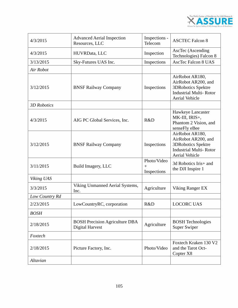
105
4/3/2015 Advanced Aerial Inspection Resources, LLC
Inspections - Telecom ASCTEC Falcon 8
4/3/2015 HUVRData, LLC Inspection AscTec (Ascending Technologies) Falcon 8
3/13/2015 Sky-Futures UAS Inc. Inspections AscTec Falcon 8 UAS Air Robot
3/12/2015 BNSF Railway Company Inspections
AirRobot AR180, AirRobot AR200, and 3DRobotics Spektre Industrial Multi- Rotor Aerial Vehicle
3D Robotics
4/3/2015 AIG PC Global Services, Inc. R&D
Hawkeye Lancaster MK-III, IRIS+, Phantom 2 Vision, and senseFly eBee
3/12/2015 BNSF Railway Company Inspections
AirRobot AR180, AirRobot AR200, and 3DRobotics Spektre Industrial Multi- Rotor Aerial Vehicle
3/11/2015 Build Imagery, LLC
Photo/Video + Inspections
3d Robotics Iris+ and the DJI Inspire 1
Viking UAS
3/3/2015 Viking Unmanned Aerial Systems, Inc. Agriculture Viking Ranger EX
Low Country Rd
2/23/2015 LowCountryRC, corporation R&D LOCORC UAS
BOSH
2/18/2015 BOSH Precision Agriculture DBA Digital Harvest Agriculture BOSH Technologies
Super Swiper
Foxtech
2/18/2015 Picture Factory, Inc. Photo/Video Foxtech Kraken 130 V2 and the Tarot Oct-Copter X8
Altavian
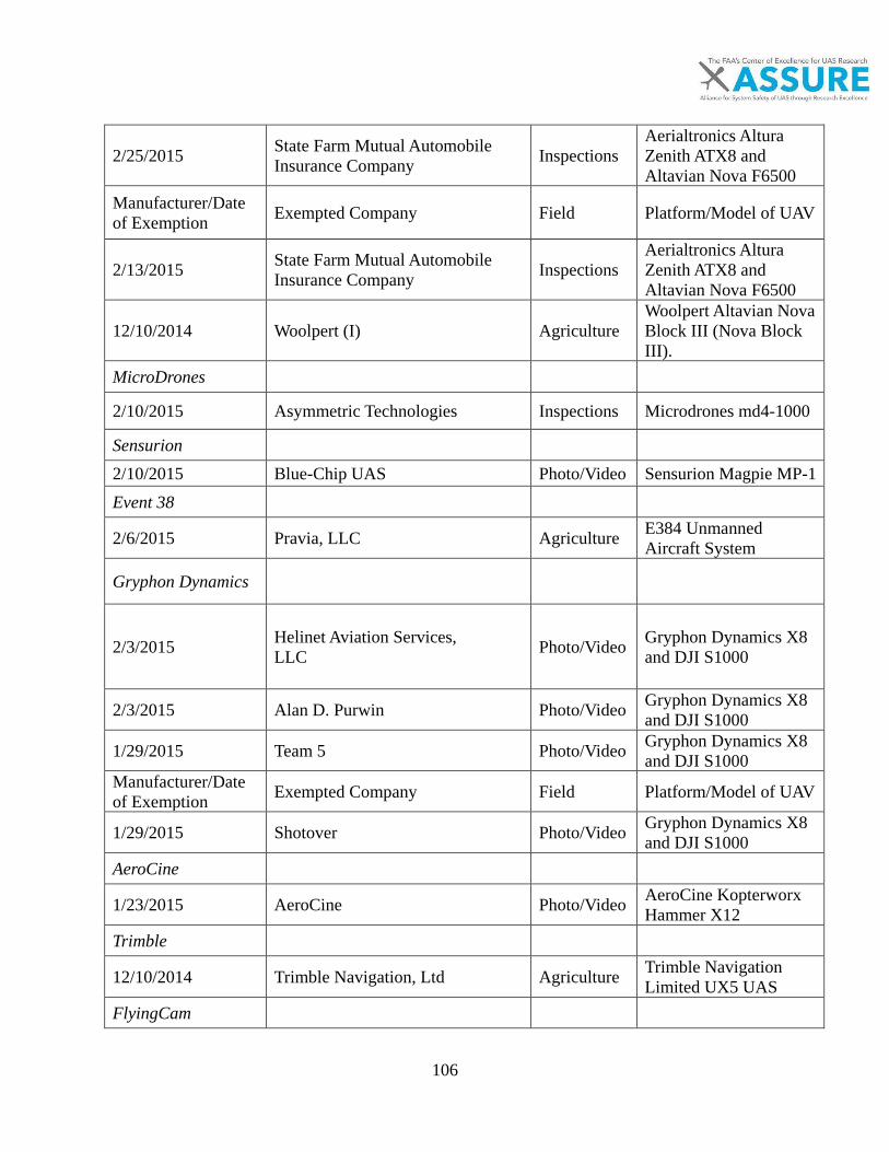
106
2/25/2015 State Farm Mutual Automobile Insurance Company Inspections
Aerialtronics Altura Zenith ATX8 and Altavian Nova F6500
Manufacturer/Date of Exemption Exempted Company Field Platform/Model of UAV
2/13/2015 State Farm Mutual Automobile Insurance Company Inspections
Aerialtronics Altura Zenith ATX8 and Altavian Nova F6500
12/10/2014 Woolpert (I) Agriculture Woolpert Altavian Nova Block III (Nova Block III).
MicroDrones
2/10/2015 Asymmetric Technologies Inspections Microdrones md4-1000
Sensurion
2/10/2015 Blue-Chip UAS Photo/Video Sensurion Magpie MP-1 Event 38
2/6/2015 Pravia, LLC Agriculture E384 Unmanned Aircraft System
Gryphon Dynamics
2/3/2015 Helinet Aviation Services, LLC Photo/Video Gryphon Dynamics X8
and DJI S1000
2/3/2015 Alan D. Purwin Photo/Video Gryphon Dynamics X8 and DJI S1000
1/29/2015 Team 5 Photo/Video Gryphon Dynamics X8 and DJI S1000
Manufacturer/Date of Exemption Exempted Company Field Platform/Model of UAV
1/29/2015 Shotover Photo/Video Gryphon Dynamics X8 and DJI S1000
AeroCine
1/23/2015 AeroCine Photo/Video AeroCine Kopterworx Hammer X12
Trimble
12/10/2014 Trimble Navigation, Ltd Agriculture Trimble Navigation Limited UX5 UAS
FlyingCam

107
10/10/2014 Flying Cam Photo/Video Flying-Cam 3.0 SARAH
Astraeus Aerial
9/25/2014 Astraeus Aerial Photo/Video Astraeus Aerial Cinema System V.3CS UAS
Hexacrafter
9/25/2014 Aerial MOB Photo/Video
HexaCrafter HC-1100, Aeronavics SkyJib 8 v.2 Heavy Lifter, Aerial MOB Discovery Pro Light Lifter, and the Aerial MOB Halo 8 Heavy Lifter
Manufacturer/Date of Exemption Exempted Company Field Platform/Model of UAV
Aeronavics
4/3/2015 Elevated Perspective Media Photo/Film Aervonics Sky Jib frame with a DJI A2 flight system
9/25/2014 Aerial MOB Photo/Video
HexaCrafter HC-1100, Aeronavics SkyJib 8 v.2 Heavy Lifter, Aerial MOB Discovery Pro Light Lifter, and the Aerial MOB Halo 8 Heavy Lifter
3/24/2015 Oceaneering International, Inc. Inspections / Surveys
Wookong DJI S800 and Aeronavics X4 Titanium
2/3/2015 Aerial MOB (Amended) Photo/Video
HexaCrafter HC-1100, Aeronavics SkyJib 8 v.2 Heavy Lifter, Aerial MOB Discovery Pro Light Lifter, and the Aerial MOB Halo 8 Heavy Lifter
PictorVision
2/3/2015 Pictorvision, Inc. (Amended) Photo/Video PV-14817 Multi-Rotor UAS: the PV-HL1 and the PV-HL2
9/25/2014 Pictorvision Photo/Video PV- 14817, PVHL1 and PV-HL2.

108
Manufacturer/Date of Exemption Exempted Company Field Platform/Model of UAV
HeliVision Productions
9/25/2014 HeliVideo Productions Photo/Video HVP- 14301 Multi Rotor
Snaproll Media
9/25/2014 Snaproll Media Photo/Video SnapRoll Media SUAS. Drone Fleet
4/3/2015 Drone Fleet & Aerospace Management, Inc. Inspections
DJI S1000, DJI Phantom 2, and Drone- Fleet Carbon Fiber V5
Vanguard Industries
4/3/2015 Aviation Unmanned Inspections
Vanguard Defense Industries ShadowHawk and MLB Company Super Bat
MLB Company
4/3/2015 Aviation Unmanned Inspections
Vanguard Defense Industries ShadowHawk and MLB Company Super Bat
Aerovironment
Manufacturer/Date of Exemption Exempted Company Field Platform/Model of UAV
4/3/2015 AeroVironment, Inc. General Use Puma AE DDL First Aerial Responder
4/3/2015 Avigators Agriculture First Aerial Responder–Sight
Precision Hawk
4/3/2015 AIG PC Global Services, Inc. R&D
Hawkeye Lancaster MK-III, IRIS+, Phantom 2 Vision, and senseFly eBee
4/3/2015 United Services Automobile Association R&D PrecisionHawk
Lancaster HawkEye FreeFly

109
4/3/2015 AirRaid Aerials, LLC
Inspections - Oil&Gas CineStar 8

A.5 UAS Maintenance, Modification, Repair, Inspection, Training, and Certification Considerations
TASK 4C: DEVELOP MAINTENANCE TECHNICIAN TRAINING REQUIREMENTS:
In-Depth Analysis of Areas that Require Special Considerations
I. Non-Metallic material structures II. Ground control stations and support equipment
III. Communication links IV. Software and autopilots
ii
NOTICE
This document is disseminated under the sponsorship of the U.S. Department of Transportation in the interest of information exchange. The U.S. Government assumes no liability for the contents or use thereof. The U.S. Government does not endorse products or manufacturers. Trade or manufacturers’ names appear herein solely because they are considered essential to the objective of this report. The findings and conclusions in this report are those of the author(s) and do not necessarily represent the views of the funding agency. This document does not constitute FAA policy. Consult the FAA sponsoring organization listed on the Technical Documentation page as to its use.

iii
Legal Disclaimer: The FAA has sponsored this project through the Center of Excellence for Unmanned Aircraft Systems. However, the agency neither endorses nor rejects the findings of this research. The presentation of this information is in the interest of invoking technical com-ment on the results and conclusions of the research.

iv
Technical Report Documentation Page Title: .5 UAS Maintenance, Modification, Repair, Inspection, Training, and Certification Considerations Non-metallic materials Report Date: 6 November 2017 Performing Organizations: Kansas State University (KSU) Authors: Dr. Kurt Barnhart, Charles Nick, Caleb Scott
Performing Organization Address: Kansas State University Sponsored Programs 2323 Anderson Ave, Suite 600 Manhattan, KS 66502
Sponsoring Agency Name and Address: U.S. Department of Transportation Federal Aviation Administration Washington, DC 20591

v
TABLE OF CONTENTS
1 EXECUTIVE SUMMARY .......................................................................................................... 1
2 SCOPE ................................................................................................................................... 2
3 INTRODUCTION .................................................................................................................... 3
4 IN-DEPTH ANALYSIS .............................................................................................................. 4
4.1 LITERATURE REVIEW .................................................................................................................... 4 4.2 CURRENT MAINTENANCE PRACTICES FOR CONTROL STATIONS AND SUPPORT EQUIPMENT ....................... 12
5 RECOMMENDATIONS .......................................................................................................... 20
5.1 SKILLS ACQUIRED THROUGH CURRENT AC 65-2D REQUIREMENTS .................................................... 22 5.2 SKILLS NOT FOUND IN AC 65-2D ................................................................................................ 23 5.3 CONCLUSIONS .......................................................................................................................... 24
6 REFERENCES ........................................................................................................................ 26

vi
LIST OF FIGURES
FIGURE 4-1. FLOW OF MANNED AIRCRAFT CONTROL .................................................................. 10
FIGURE 4-2. FLOW OF UNMANNED AIRCRAFT CONTROL ............................................................. 11
LIST OF TABLES
TABLE 2-1. A5 WORK BREAKDOWN STRUCTURE ............................................................................ 2
TABLE 4-1. CONTROL STATION CATEGORIES ................................................................................... 5
TABLE 4-2. TYPES OF LAUNCH EQUIPMENT .................................................................................... 6
TABLE 4-3. TYPES OF RECOVERY EQUIPMENT ................................................................................. 7
TABLE 4-4. TYPES OF MISCELLANEOUS EQUIPMENT ...................................................................... 9
TABLE 4-6. PRIMARY CONTROL STATION COMPONENTS ............................................................. 13
TABLE 5-1 PRIMARY SKILLS FOR CONTROL STATIONS AND SUPPORT EQUIPMENT ..................... 20
1
1 EXECUTIVE SUMMARY
Control stations (CS) and support equipment (SE) were evaluated as a part of an unmanned aircraft system (UAS) to discover unique maintenance considerations. Current maintenance tasks and industry standards were evaluated to determine what skills a maintainer should have in order to maintain these components of a UAS. CS is essentially the equivalent of the manned cockpit. The major difference is that the operator and CS are separated physically from the UA during operation by way of communication links. This separation requires that maintainers keep the CS and unmanned aircraft (UA) safe-for-operation with some additional considerations such as differing operational conditions and the introduction of tools such as maintenance terminals which can be used to test the aircraft separate of the CS. As a means of facilitating and producing an operator interface most CS utilize computing devices that more closely resemble consumer electronics than the computers found in manned aircraft. After evaluating maintenance tasks currently being conducted on CS and support equipment, and review-ing industry standards for skill and knowledge, a set of primary skills were identified that represent the skills a maintainer needs to effectively maintain CS and support equipment. These skills include focus areas such as microcomputers, networks, electrical systems, pneumatics and hydraulics. After comparing these skillsets to the current requirement for Part 65 certified mechanics, the recommendation for a Part 65 mechanic requires additional training in the primary skills of microcomputers and networks.
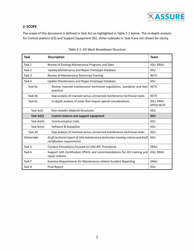
2
2 SCOPE
The scope of this document is defined in Task 4cii as highlighted in Table 2-1 below: The in-depth analysis for Control stations (CS) and Support Equipment (SE). Other subtasks in Task 4 are not shown for clarity.
Table 2-1. A5 Work Breakdown Structure
Task Description Team
Task 1 Review of Existing Maintenance Programs and Data KSU, ERAU
Task 2 Update Maintenance and Repair Prototype Database KSU
Task 3 Review of Maintenance Technician Training NCTC
Task 4 Update Maintenance and Repair Prototype Database KSU
Task 4a Review manned maintenance technician regulations, standards and best practices
NCTC
Task 4b Gap analysis of manned versus unmanned maintenance technician tasks NCTC
Task 4c In-depth analysis of areas that require special considerations KSU, ERAU MTSU NCTC
Task 4c(i) Non-metallic Material Structures KSU
Task 4c(ii) Control stations and support equipment KSU
Task 4c(iii) Communication Links KSU
Task 4c(iv) Software & Autopilots KSU
Task 4d Gap analysis of manned versus unmanned maintenance technician tasks KSU
Deliverable Draft technical report of UAS maintenance technician training criteria and draft certification requirements
KSU
Task 5 Conduct Simulations Focused on UAS-ATC Procedures ERAU
Task 6 Support UAS Certification Efforts and recommendations for ASI training and repair stations
KSU, ERAU
Task 7 Examine Requirements for Maintenance-related Accident Reporting ERAU
Task 8 Final Report KSU
3
3 INTRODUCTION
One of the goals of Task 4 of the A.5 project is to determine where current manned aviation standards meet the requirements to maintain unmanned aircraft systems (UAS) and where new skill requirements must be developed for UAS maintainers. Four major areas of special considerations were identified at the beginning of the project that was new and unique compared to manned aviation that required in-depth analysis. These areas include non-metallic material structures, control stations and support equipment, communication links and software and autopilots. This report focuses on control stations (CS) and support equipment (SE). UAS contain several physically separate components working together to perform a flight operation. CS and support equipment are prime examples of physically separate components as they provide important roles in the operation of UAS. The CS provides an interface for the operator to monitor and control the aircraft and its payload, similar to the cockpit of a manned aircraft. Support equipment provides the addi-tional tools required to ensure a safe operation during preparation, launch and recovery. The roles that CS and support equipment fill in UAS ensure a safe and successful flight; therefore, the maintenance of these components are as critical as the unmanned aircraft (UA) itself. The following sec-tions will detail the varying levels of importance of different types of CS and support equipment in a system while providing important taxonomies to more easily understand the applications of maintenance. Certified manned aviation maintainers have a diverse set of skills as detailed in 14 CFR Part 65, providing two options for certification to perform maintenance on airplanes: an Airframe license and/or a Power-plant license. The segment of the skills and training based on the varying types of systems used for manned aviation highlights the primary differences of the UAS industry, which is the lack of the knowledge and skills required to complete the maintenance tasks of CS and support equipment for UAS since this tech-nology is unique in its roles for flight operations.
4
4 IN-DEPTH ANALYSIS
The in-depth analysis reviewed relevant literature and current maintenance practices in the UAS industry
today. Since this industry is relatively new a smaller amount of sources were discovered than normal, but
this was sufficient for creating initial taxonomies for CS and SE.
4.1 Literature Review
To gather a base of knowledge on CS and support equipment, relevant sources of information were iden-tified and reviewed for data, facts and discussion about CS and support equipment maintenance. The fol-lowing 12 sources were reviewed for context and findings related to CS and support equipment:
• ASTM D2909-14 Standard Practice for Maintenance and Continued Airworthiness of Small Un-manned Aircraft Systems (sUAS) [1]
• AUVSI – UAS Platform Database [2] • Introduction to Unmanned Aircraft Systems (2nd edition) by Marshall, D. M., Barnhart, R. K., Shap-
pee, E., & Most, M. [3] • Human Challenges in the Maintenance of Unmanned Aircraft Systems by Hobbs, A., & Herwitz [4] • Human Factor Challenges of Remotely Piloted Aircraft by Hobbs, A., & Shively, R. J. [5] • Human Factors in the Maintenance of Unmanned Aircraft by Hobbs, A., & Herwitz [6] • Maintenance Challenges of Small Unmanned Aircraft Systems - A Human Factors Perspective by
Hobbs, A., & Herwitz [7] • U.S. Air Force Fact Sheets [8] • U.S. Army Unmanned Aircraft Systems Repairer (15E) career profile [9] • U.S. Army Unmanned Aircraft Systems Operator (15W) career profile [10] • U.S. Air Force Remotely Piloted Aircraft Maintenance career profile [11] • U.S. Marines MOS 6314 Avionics/Maintenance Technician, Unmanned Aircraft System (UAS) ca-
reer profile [12] Studying the sources above resulted in better understanding categorization, definitions, variations in equipment, certification of military UAS maintainers compared to Part 65 certified maintainers, unique maintenance considerations for CS and support equipment, and discussions of risks to maintenance per-sonnel. The context created by these findings provided a more complete understanding of CS and support equipment detailing the tasks, skills and training currently in use by the UAS industry. The next two sec-tions discuss the primary differences for CS and support equipment.
4.1.1 Introduction to Control stations
ASTM International (2014) [1] defines control stations (CS) as, “a land- or sea-based control center that provides the facilities for human control of sUA”. Based on this definition, CS is the interface for the oper-ator to manually control the aircraft. After reviewing several control stations currently used in operations,
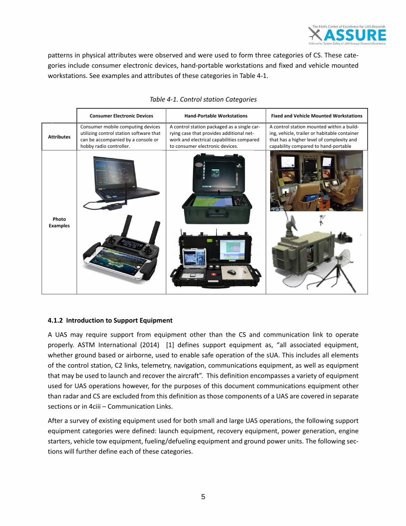
5
patterns in physical attributes were observed and were used to form three categories of CS. These cate-gories include consumer electronic devices, hand-portable workstations and fixed and vehicle mounted workstations. See examples and attributes of these categories in Table 4-1.
Table 4-1. Control station Categories
Consumer Electronic Devices Hand-Portable Workstations Fixed and Vehicle Mounted Workstations
Attributes
Consumer mobile computing devices utilizing control station software that can be accompanied by a console or hobby radio controller.
A control station packaged as a single car-rying case that provides additional net-work and electrical capabilities compared to consumer electronic devices.
A control station mounted within a build-ing, vehicle, trailer or habitable container that has a higher level of complexity and capability compared to hand-portable
Photo Examples
4.1.2 Introduction to Support Equipment
A UAS may require support from equipment other than the CS and communication link to operate properly. ASTM International (2014) [1] defines support equipment as, “all associated equipment, whether ground based or airborne, used to enable safe operation of the sUA. This includes all elements of the control station, C2 links, telemetry, navigation, communications equipment, as well as equipment that may be used to launch and recover the aircraft”. This definition encompasses a variety of equipment used for UAS operations however, for the purposes of this document communications equipment other than radar and CS are excluded from this definition as those components of a UAS are covered in separate sections or in 4ciii – Communication Links.
After a survey of existing equipment used for both small and large UAS operations, the following support equipment categories were defined: launch equipment, recovery equipment, power generation, engine starters, vehicle tow equipment, fueling/defueling equipment and ground power units. The following sec-tions will further define each of these categories.
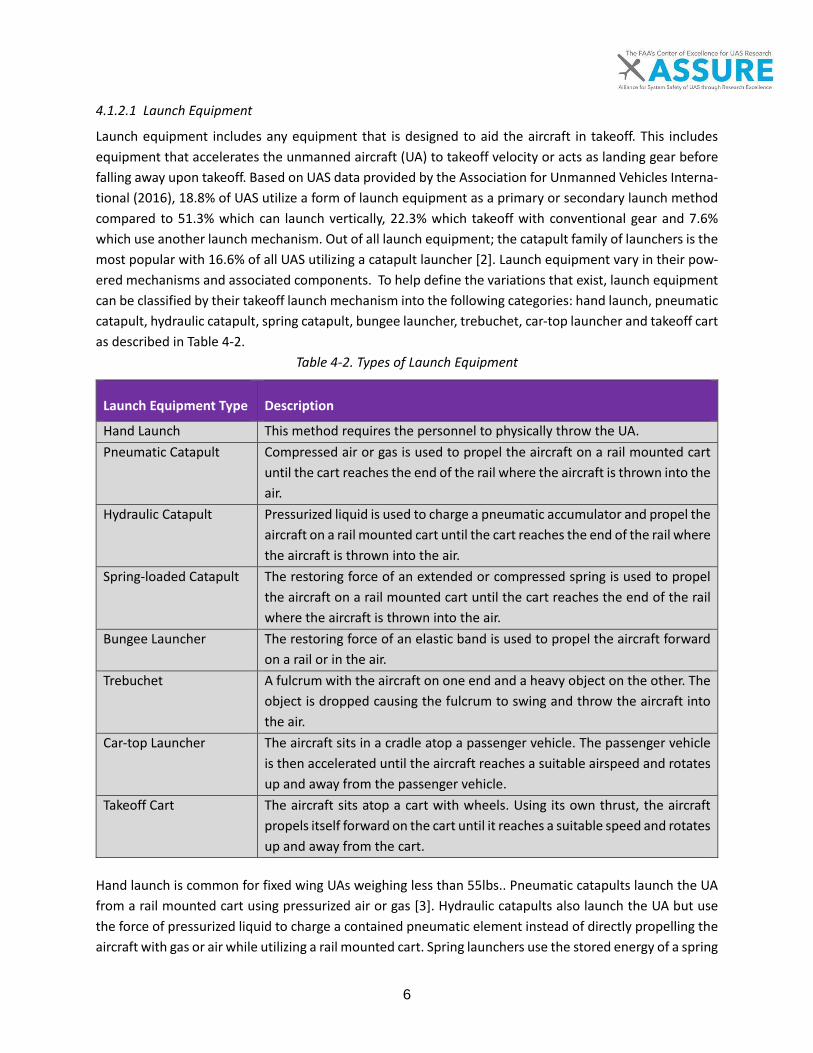
6
4.1.2.1 Launch Equipment
Launch equipment includes any equipment that is designed to aid the aircraft in takeoff. This includes equipment that accelerates the unmanned aircraft (UA) to takeoff velocity or acts as landing gear before falling away upon takeoff. Based on UAS data provided by the Association for Unmanned Vehicles Interna-tional (2016), 18.8% of UAS utilize a form of launch equipment as a primary or secondary launch method compared to 51.3% which can launch vertically, 22.3% which takeoff with conventional gear and 7.6% which use another launch mechanism. Out of all launch equipment; the catapult family of launchers is the most popular with 16.6% of all UAS utilizing a catapult launcher [2]. Launch equipment vary in their pow-ered mechanisms and associated components. To help define the variations that exist, launch equipment can be classified by their takeoff launch mechanism into the following categories: hand launch, pneumatic catapult, hydraulic catapult, spring catapult, bungee launcher, trebuchet, car-top launcher and takeoff cart as described in Table 4-2.
Table 4-2. Types of Launch Equipment
Launch Equipment Type Description
Hand Launch This method requires the personnel to physically throw the UA. Pneumatic Catapult Compressed air or gas is used to propel the aircraft on a rail mounted cart
until the cart reaches the end of the rail where the aircraft is thrown into the air.
Hydraulic Catapult Pressurized liquid is used to charge a pneumatic accumulator and propel the aircraft on a rail mounted cart until the cart reaches the end of the rail where the aircraft is thrown into the air.
Spring-loaded Catapult The restoring force of an extended or compressed spring is used to propel the aircraft on a rail mounted cart until the cart reaches the end of the rail where the aircraft is thrown into the air.
Bungee Launcher The restoring force of an elastic band is used to propel the aircraft forward on a rail or in the air.
Trebuchet A fulcrum with the aircraft on one end and a heavy object on the other. The object is dropped causing the fulcrum to swing and throw the aircraft into the air.
Car-top Launcher The aircraft sits in a cradle atop a passenger vehicle. The passenger vehicle is then accelerated until the aircraft reaches a suitable airspeed and rotates up and away from the passenger vehicle.
Takeoff Cart The aircraft sits atop a cart with wheels. Using its own thrust, the aircraft propels itself forward on the cart until it reaches a suitable speed and rotates up and away from the cart.
Hand launch is common for fixed wing UAs weighing less than 55lbs.. Pneumatic catapults launch the UA from a rail mounted cart using pressurized air or gas [3]. Hydraulic catapults also launch the UA but use the force of pressurized liquid to charge a contained pneumatic element instead of directly propelling the aircraft with gas or air while utilizing a rail mounted cart. Spring launchers use the stored energy of a spring
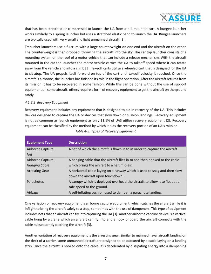
7
that has been stretched or compressed to launch the UA from a rail-mounted cart. A bungee launcher works similarly to a spring launcher but uses a stretched elastic band to launch the UA. Bungee launchers are typically used with very small and light unmanned aircraft [3].
Trebuchet launchers use a fulcrum with a large counterweight on one end and the aircraft on the other. The counterweight is then dropped, throwing the aircraft into the sky. The car top launcher consists of a mounting system on the roof of a motor vehicle that can include a release mechanism. With the aircraft mounted in the car top launcher the motor vehicle carries the UA to takeoff speed where it can rotate away from the vehicle and into a climb [3]. Takeoff carts utilize a wheeled cart that is designed for the UA to sit atop. The UA propels itself forward on top of the cart until takeoff velocity is reached. Once the aircraft is airborne, the launcher has finished its role in the flight operation. After the aircraft returns from its mission it has to be recovered in some fashion. While this can be done without the use of support equipment on some aircraft, others require a form of recovery equipment to get the aircraft on the ground safely.
4.1.2.2 Recovery Equipment
Recovery equipment includes any equipment that is designed to aid in recovery of the UA. This includes devices designed to capture the UA or devices that slow down or cushion landings. Recovery equipment is not as common as launch equipment as only 11.1% of UAS utilize recovery equipment [2]. Recovery equipment can be classified by the method by which it aids the recovery portion of an UA’s mission.
Table 4-3. Types of Recovery Equipment
Equipment Type Description
Airborne Capture: Net
A net of which the aircraft is flown in to in order to capture the aircraft.
Airborne Capture: Hanging Cable
A hanging cable that the aircraft flies in to and then hooked to the cable which brings the aircraft to a halt mid-air.
Arresting Gear A horizontal cable laying on a runway which is used to snag and then slow down the aircraft upon touchdown.
Parachutes A canopy which is deployed overhead the aircraft to allow it to float at a safe speed to the ground.
Airbags A self-inflating cushion used to dampen a parachute landing. One variation of recovery equipment is airborne capture equipment, which catches the aircraft while it is inflight to bring the aircraft safely to a stop, sometimes with the use of dampeners. This type of equipment includes nets that an aircraft can fly into capturing the UA [3]. Another airborne capture device is a vertical cable hung by a crane which an aircraft can fly into and a hook onboard the aircraft connects with the cable subsequently catching the aircraft [3]. Another variation of recovery equipment is the arresting gear. Similar to manned naval aircraft landing on the deck of a carrier, some unmanned aircraft are designed to be captured by a cable laying on a landing strip. Once the aircraft is hooked onto the cable, it is decelerated by dissipating energy into a dampening
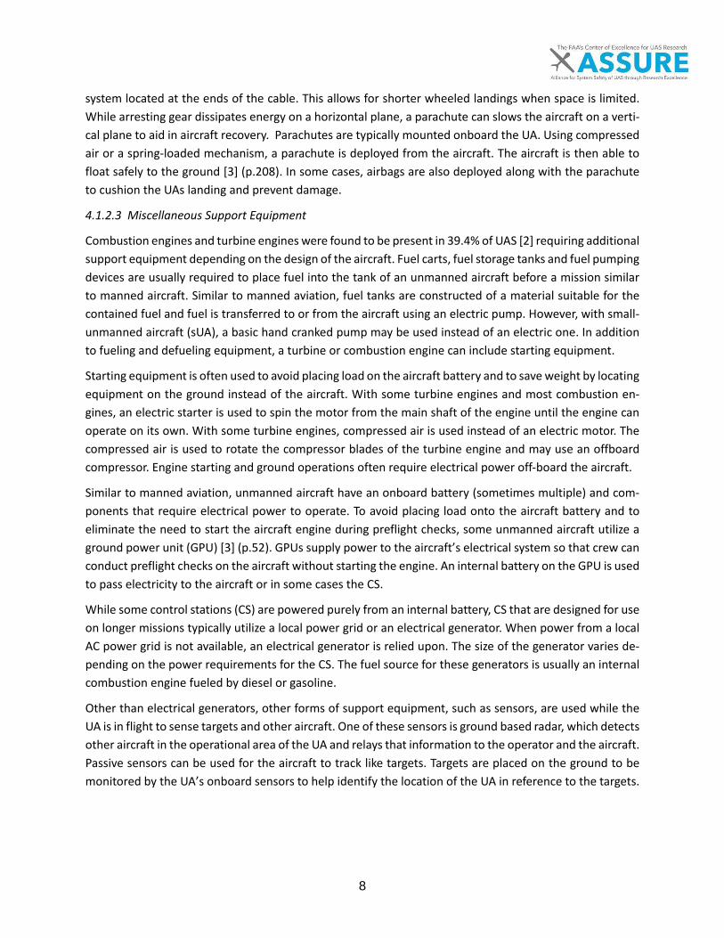
8
system located at the ends of the cable. This allows for shorter wheeled landings when space is limited. While arresting gear dissipates energy on a horizontal plane, a parachute can slows the aircraft on a verti-cal plane to aid in aircraft recovery. Parachutes are typically mounted onboard the UA. Using compressed air or a spring-loaded mechanism, a parachute is deployed from the aircraft. The aircraft is then able to float safely to the ground [3] (p.208). In some cases, airbags are also deployed along with the parachute to cushion the UAs landing and prevent damage.
4.1.2.3 Miscellaneous Support Equipment
Combustion engines and turbine engines were found to be present in 39.4% of UAS [2] requiring additional support equipment depending on the design of the aircraft. Fuel carts, fuel storage tanks and fuel pumping devices are usually required to place fuel into the tank of an unmanned aircraft before a mission similar to manned aircraft. Similar to manned aviation, fuel tanks are constructed of a material suitable for the contained fuel and fuel is transferred to or from the aircraft using an electric pump. However, with small-unmanned aircraft (sUA), a basic hand cranked pump may be used instead of an electric one. In addition to fueling and defueling equipment, a turbine or combustion engine can include starting equipment.
Starting equipment is often used to avoid placing load on the aircraft battery and to save weight by locating equipment on the ground instead of the aircraft. With some turbine engines and most combustion en-gines, an electric starter is used to spin the motor from the main shaft of the engine until the engine can operate on its own. With some turbine engines, compressed air is used instead of an electric motor. The compressed air is used to rotate the compressor blades of the turbine engine and may use an offboard compressor. Engine starting and ground operations often require electrical power off-board the aircraft.
Similar to manned aviation, unmanned aircraft have an onboard battery (sometimes multiple) and com-ponents that require electrical power to operate. To avoid placing load onto the aircraft battery and to eliminate the need to start the aircraft engine during preflight checks, some unmanned aircraft utilize a ground power unit (GPU) [3] (p.52). GPUs supply power to the aircraft’s electrical system so that crew can conduct preflight checks on the aircraft without starting the engine. An internal battery on the GPU is used to pass electricity to the aircraft or in some cases the CS.
While some control stations (CS) are powered purely from an internal battery, CS that are designed for use on longer missions typically utilize a local power grid or an electrical generator. When power from a local AC power grid is not available, an electrical generator is relied upon. The size of the generator varies de-pending on the power requirements for the CS. The fuel source for these generators is usually an internal combustion engine fueled by diesel or gasoline.
Other than electrical generators, other forms of support equipment, such as sensors, are used while the UA is in flight to sense targets and other aircraft. One of these sensors is ground based radar, which detects other aircraft in the operational area of the UA and relays that information to the operator and the aircraft. Passive sensors can be used for the aircraft to track like targets. Targets are placed on the ground to be monitored by the UA’s onboard sensors to help identify the location of the UA in reference to the targets.
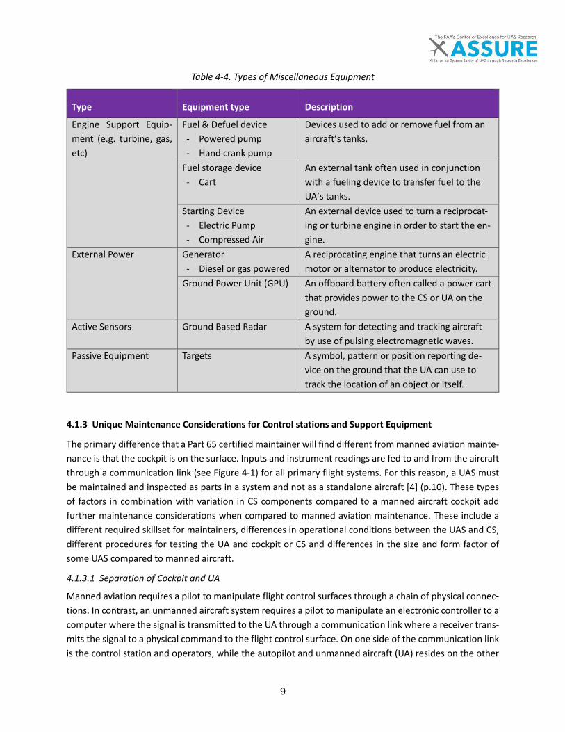
9
Table 4-4. Types of Miscellaneous Equipment
Type Equipment type Description
Engine Support Equip-ment (e.g. turbine, gas, etc)
Fuel & Defuel device - Powered pump - Hand crank pump
Devices used to add or remove fuel from an aircraft’s tanks.
Fuel storage device - Cart
An external tank often used in conjunction with a fueling device to transfer fuel to the UA’s tanks.
Starting Device - Electric Pump - Compressed Air
An external device used to turn a reciprocat-ing or turbine engine in order to start the en-gine.
External Power Generator - Diesel or gas powered
A reciprocating engine that turns an electric motor or alternator to produce electricity.
Ground Power Unit (GPU) An offboard battery often called a power cart that provides power to the CS or UA on the ground.
Active Sensors Ground Based Radar A system for detecting and tracking aircraft by use of pulsing electromagnetic waves.
Passive Equipment Targets A symbol, pattern or position reporting de-vice on the ground that the UA can use to track the location of an object or itself.
4.1.3 Unique Maintenance Considerations for Control stations and Support Equipment
The primary difference that a Part 65 certified maintainer will find different from manned aviation mainte-nance is that the cockpit is on the surface. Inputs and instrument readings are fed to and from the aircraft through a communication link (see Figure 4-1) for all primary flight systems. For this reason, a UAS must be maintained and inspected as parts in a system and not as a standalone aircraft [4] (p.10). These types of factors in combination with variation in CS components compared to a manned aircraft cockpit add further maintenance considerations when compared to manned aviation maintenance. These include a different required skillset for maintainers, differences in operational conditions between the UAS and CS, different procedures for testing the UA and cockpit or CS and differences in the size and form factor of some UAS compared to manned aircraft.
4.1.3.1 Separation of Cockpit and UA
Manned aviation requires a pilot to manipulate flight control surfaces through a chain of physical connec-tions. In contrast, an unmanned aircraft system requires a pilot to manipulate an electronic controller to a computer where the signal is transmitted to the UA through a communication link where a receiver trans-mits the signal to a physical command to the flight control surface. On one side of the communication link is the control station and operators, while the autopilot and unmanned aircraft (UA) resides on the other

10
side of the link. See Figure 4-1 and Figure 4-2. This requires that inspections or maintenance tasks need to be performed cooperatively between multiple elements of the UAS. Some examples of CS inspections include testing communication link equipment, control input response, and relay of voice communications [7] (p.13).
In some cases, the UA is operated by two different crews and two different CS: the Launch and Recovery Element (LRE) and the Mission Control Element (MCE). The LRE is located within line of sight of the aircraft launch site and handles the initial and final stage of a mission, while the MCE can be located anywhere in the world and handles most of the mission except for launch and recovery (RQ-4 Global Hawk, 2014). Since the MCE station may not be located near the UA, the type of maintenance that can be conducted may be limited. For example, the maintainer may not be able to test both the UA and the CS simultaneously without coordination between crews located with the aircraft and with the CS.
To allow functional checks, updates and other maintenance operations to be conducted without the use of a CS a tool called a maintenance terminal can be used. These terminals are usually a cart or laptop computer(s) which utilize software and a wired connection to the aircraft to perform functions that would otherwise require the use of a communication link and CS.
Support equipment, while also separate from the UA, do not always require testing be conducted on both the UA and support equipment simultaneously. A few examples of this would be using a dummy load to test a launcher or testing a generator for proper compression. Support equipment of some varieties are not utilized except during a short portion of the mission. Therefore, some support equipment such as the UAV Factory Penguin Launcher have their maintenance intervals based primarily off the number of cycles that have occured. Separation of the UA from parts of the UAS on the surface leads to different environ-ments being experienced by the UA and surface equipment.
Figure 4-1. Flow of Manned Aircraft Control
Pilot Input Yoke/Stick Cables, Hydraulics, etc...
Flight Control Surfaces

11
Figure 4-2. Flow of Unmanned Aircraft Control
4.1.3.2 Environmental Factors
Separation of the operator and cockpit from the UA results in differing environmental exposures for the CS [13] (p.72). The UA will experience an environment like that of manned aircraft including temperature extremes, wind, g-force, moisture and vibration, however the CS experiences only environmental factors present on the surface like dirt, dust and surface traffic. Thus, the CS may experience greater exposure to certain conditions and less exposure to other conditions compared to the UA. Exposure to dirt or dust can be of concern for computing equipment within a CS especially when those devices are designed for con-sumer use rather than field use.
4.1.3.3 Widespread Use of Consumer Electronics
The widespread use of consumer electronic devices, particularly personal computers, is another unique aspect of UAS and their respective CS [5] (p.3). For this reason, a maintainer will need familiarity with Windows, Linux and other operating systems, computer hardware and the application software for the CS [4] (p.10) along with any input devices. Refer to Task 4civ – Software and Autopilots for more information on software.
The use of personal computers for UAS provides a large gap in contrast to manned aircraft, which use a purpose built, certified flight computer designed for very specific and limited operations. Consumer elec-tronics are not held to the same standard as the flight computers found within manned aircraft, these components are more likely to have less guidance from the manufacturer on maintenance and to be re-paired through methods such as manufacturer servicing or complete replacement of those components. One benefit to using consumer electronics is the ability to easily transport or ship to a manufacturer or third party repair station.
4.1.3.4 Transport of UAS
Transporting a UAS can be substantially different from manned aircraft. According to Alan Hobbs [6] (p.4), small unmanned aerial systems (sUAS) are simple to repair and transport. This is due to the size of the aircraft and in some cases the CS is small enough to carry by hand and even ship to a repair facility. In manned aviation, an aircraft in need of repair would not be able to be shipped or packed into a passenger vehicle, such as a light truck or van. However, with small UAS, sending an aircraft through a parcel service
Pilot InputGCS Interface and Computer
Ground and Air Transceiver Communication
Aircraft Processor ServomotorFlight Control Surfaces
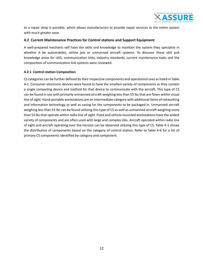
12
to a repair shop is possible, which allows manufacturers to provide repair services to the entire system with much greater ease.
4.2 Current Maintenance Practices for Control stations and Support Equipment
A well-prepared mechanic will have the skills and knowledge to maintain the system they specialize in whether it be automobiles, airline jets or unmanned aircraft systems. To discover these skill and knowledge areas for UAS, communication links, industry standards, current maintenance tasks and the composition of communication link systems were reviewed.
4.2.1 Control station Composition
CS categories can be further defined by their respective components and operational uses as listed in Table 4-1. Consumer electronic devices were found to have the smallest variety of components as they contain a single computing device and method for that device to communicate with the aircraft. This type of CS can be found in use with primarily unmanned aircraft weighing less than 55 lbs that are flown within visual line of sight. Hand-portable workstations are an intermediate category with additional items of networking and information technology as well as casing for the components to be packaged in. Unmanned aircraft weighing less than 55 lbs can be found utilizing this type of CS as well as unmanned aircraft weighing more than 55 lbs that operate within radio line of sight. Fixed and vehicle mounted workstations have the widest variety of components and are often used with large and complex UAs. Aircraft operated within radio line of sight and aircraft operating over the horizon can be observed utilizing this type of CS. Table 4-1 shows the distribution of components based on the category of control station. Refer to Table 4-6 for a list of primary CS components identified by category and component.

13
Table 4-5. Primary Control Station Components

14
4.2.2 Support Equipment Composition
Variations of support equipment can also be broken down by their primary components. The source of information for this section is limited to the most typical forms of support equipment. For example, rocket assisted launchers are not included since they are not commonly used in the UAS industry today.
4.2.2.1 Launch Equipment Components
Launch equipment components can be divided into structural components, mechanical wear components, electrical/control components, and energy storage components. Mechanical wear components include bearings, bushings, and slides used in the process of accelerating the aircraft to takeoff speed. Once the aircraft is airborne then brakes, shock absorbers, and stops may be utilized to dampen the energy of an aircraft carrying mechanism at the end of travel. Electrical components are sometimes incorporated in the launcher control systems for either manual or autonomous launching configurations. Elements of the electronic systems include power supplies, control console, wiring, valves, indicators, and sensors/limit switches.
Launching systems can be passive in nature, providing aircraft support (car-top launchers or takeoff carts), or active (storing and releasing energy for launch). Energy storage components for active systems vary depending on the specific launcher. Pneumatic launchers commonly employ a dedicated air compressor, tank, lines, and fittings. Pressurized gas is expelled directly into the atmosphere from the pneumatic launcher once the aircraft has accelerated to takeoff speed. Hydraulic launchers contain the pneumatic portion of an element such as a nitrogen accumulator. A hydraulic pump transfers fluid from a holding tank, applying force against the accumulator to charge it, then a hydraulic piston transfers the energy to the aircraft carrier. Mechanical launchers store energy in the form of a spring or bungee. Electric or man-ual winches commonly charge these systems.
4.2.2.2 Recovery Equipment Components
Manual or electric winches, as well as hydraulic systems, are commonly used to deploy net and cable recovery systems. A form of shock-absorber is common to prevent damage to the aircraft when contact is made. Deployment of parachute systems for recovery is usually handled by a self-contained gas canister or spring mechanism triggered by the flight-controller. The Penguin-C aircraft also employs an air-bag system to cushion the impact.
4.2.3 Control station and Support Equipment Maintenance Tasks
A list of current maintenance tasks for CS and support equipment was created to aid in identifying the required skills. Procedural and repair tasks were identified through Certificate of Authorization and Section 333 incident and accident reports, the NCATT Unmanned Aircraft System Maintenance Standard, the DACUM Research Chart for UAS Maintenance Technician, the Maintenance and Repair Database, United States Air Force Accident Reports and a list of tasks for a complex CS shared by Northland Community and Technical College (NCTC) called the Modified Shelter Tech Task List [14]. The incident and accident reports were primarily utilized to discover repair tasks, while all other sources were used to uncover both repair and procedural maintenance tasks. To view the entire task list and the sources of each specific task, refer to Appendix A.

15
A large majority of the tasks discovered in the aforementioned sources were related to the CS with the largest number of tasks relating to CS microcomputers. Most of tasks were preventative maintenance ra-ther than corrective. Regular tasks included updating software, preventative steps to protect hardware, data loss and remove malicious data and inspection of computing equipment to ensure proper operation. Corrective actions included primarily removal and replacement of faulty hardware and conducting resets and reboots of hardware and software.
Along with microcomputers, tasks related to networking components found in a CS were cited. These tasks were primarily regular with only a few tasks being corrective. Preventative tasks include cleaning fiber optics, configuring devices and checking operation of networking devices. Corrective tasks include trou-bleshooting and identifying faults in a network and replacing faulty devices. A handful of tasks identified also applied to internal and external voice communications including updating software, configuring the system, and removing and replacing faulty components.
The climate control system of the CS was identified as having maintenance task of its own. Inspecting and replacing air filters and dehumidifying canisters were the primary tasks identified. Other corrective tasks included removing and replacing seats for the pilots and light fixtures for the work area.
The final set of system specific maintenance tasks identified preventive and corrective maintenance con-ducted on electrical systems on both the aircraft or CS. Some of these tasks includes regular inspections of wiring and connectors. In the case corrective action is needed, tasks include troubleshooting circuits, isolating faulty electrical components and replacement of connectors and wiring.
In addition to system specific tasks, several preventative and corrective tasks were identified that cover the CS itself. These tasks ranged from scheduled inspections, pre and post operation inspections, function-ality checks, cleaning and preparing the CS for shipment. These tasks could not be linked to a single system as they are conducted on the CS as a whole.
For support equipment, maintenance and repair database entries were the only source of information for maintenance tasks. From the limited scope of tasks found within the database, a maintainer would need to be able to inspect and conduct regular replacement of components on a catapult rail and carriage, pneumatic power systems and cable-type airborne capture recovery equipment.
4.2.4 Knowledge and Skills Required to Maintain Control stations
To form a larger picture of the skill and knowledge required to maintain control stations, further infor-mation than the list of tasks discussed in Section 4.2.3 is required. Therefore, a list of skills and knowledge was created using an industry certification for UAS maintainers, the NCATT Unmanned Aircraft System (UAS) Maintenance Standard, the DACUM Research Chart for UAS Maintenance Technician [15] and the list of tasks found in Appendix A and discussed in Section 4.2.3. The full list of skills and knowledge can be found in Appendix B.
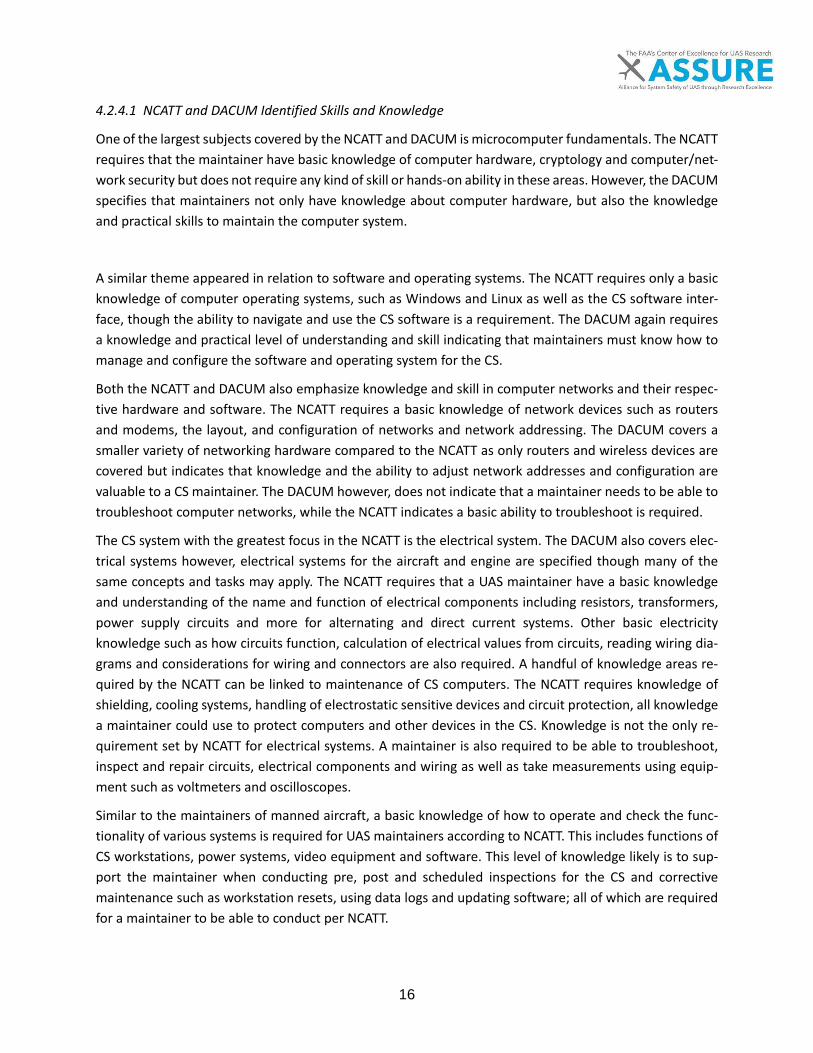
16
4.2.4.1 NCATT and DACUM Identified Skills and Knowledge
One of the largest subjects covered by the NCATT and DACUM is microcomputer fundamentals. The NCATT requires that the maintainer have basic knowledge of computer hardware, cryptology and computer/net-work security but does not require any kind of skill or hands-on ability in these areas. However, the DACUM specifies that maintainers not only have knowledge about computer hardware, but also the knowledge and practical skills to maintain the computer system.
A similar theme appeared in relation to software and operating systems. The NCATT requires only a basic knowledge of computer operating systems, such as Windows and Linux as well as the CS software inter-face, though the ability to navigate and use the CS software is a requirement. The DACUM again requires a knowledge and practical level of understanding and skill indicating that maintainers must know how to manage and configure the software and operating system for the CS.
Both the NCATT and DACUM also emphasize knowledge and skill in computer networks and their respec-tive hardware and software. The NCATT requires a basic knowledge of network devices such as routers and modems, the layout, and configuration of networks and network addressing. The DACUM covers a smaller variety of networking hardware compared to the NCATT as only routers and wireless devices are covered but indicates that knowledge and the ability to adjust network addresses and configuration are valuable to a CS maintainer. The DACUM however, does not indicate that a maintainer needs to be able to troubleshoot computer networks, while the NCATT indicates a basic ability to troubleshoot is required.
The CS system with the greatest focus in the NCATT is the electrical system. The DACUM also covers elec-trical systems however, electrical systems for the aircraft and engine are specified though many of the same concepts and tasks may apply. The NCATT requires that a UAS maintainer have a basic knowledge and understanding of the name and function of electrical components including resistors, transformers, power supply circuits and more for alternating and direct current systems. Other basic electricity knowledge such as how circuits function, calculation of electrical values from circuits, reading wiring dia-grams and considerations for wiring and connectors are also required. A handful of knowledge areas re-quired by the NCATT can be linked to maintenance of CS computers. The NCATT requires knowledge of shielding, cooling systems, handling of electrostatic sensitive devices and circuit protection, all knowledge a maintainer could use to protect computers and other devices in the CS. Knowledge is not the only re-quirement set by NCATT for electrical systems. A maintainer is also required to be able to troubleshoot, inspect and repair circuits, electrical components and wiring as well as take measurements using equip-ment such as voltmeters and oscilloscopes.
Similar to the maintainers of manned aircraft, a basic knowledge of how to operate and check the func-tionality of various systems is required for UAS maintainers according to NCATT. This includes functions of CS workstations, power systems, video equipment and software. This level of knowledge likely is to sup-port the maintainer when conducting pre, post and scheduled inspections for the CS and corrective maintenance such as workstation resets, using data logs and updating software; all of which are required for a maintainer to be able to conduct per NCATT.
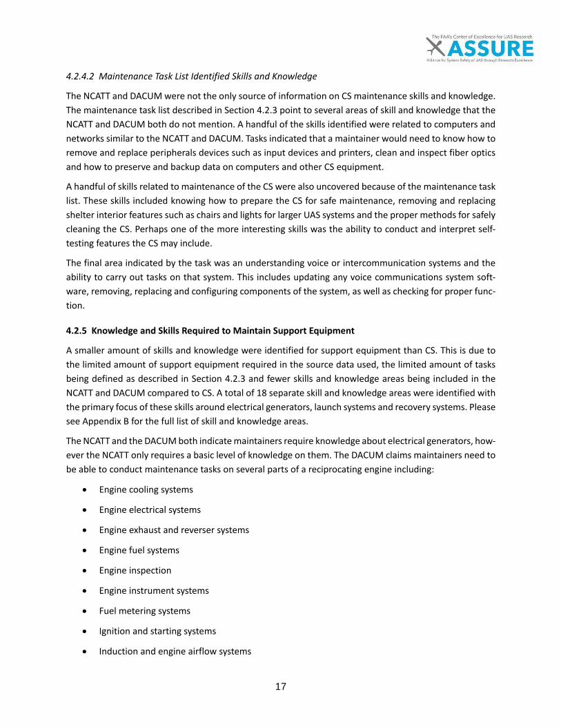
17
4.2.4.2 Maintenance Task List Identified Skills and Knowledge
The NCATT and DACUM were not the only source of information on CS maintenance skills and knowledge. The maintenance task list described in Section 4.2.3 point to several areas of skill and knowledge that the NCATT and DACUM both do not mention. A handful of the skills identified were related to computers and networks similar to the NCATT and DACUM. Tasks indicated that a maintainer would need to know how to remove and replace peripherals devices such as input devices and printers, clean and inspect fiber optics and how to preserve and backup data on computers and other CS equipment.
A handful of skills related to maintenance of the CS were also uncovered because of the maintenance task list. These skills included knowing how to prepare the CS for safe maintenance, removing and replacing shelter interior features such as chairs and lights for larger UAS systems and the proper methods for safely cleaning the CS. Perhaps one of the more interesting skills was the ability to conduct and interpret self-testing features the CS may include.
The final area indicated by the task was an understanding voice or intercommunication systems and the ability to carry out tasks on that system. This includes updating any voice communications system soft-ware, removing, replacing and configuring components of the system, as well as checking for proper func-tion.
4.2.5 Knowledge and Skills Required to Maintain Support Equipment
A smaller amount of skills and knowledge were identified for support equipment than CS. This is due to the limited amount of support equipment required in the source data used, the limited amount of tasks being defined as described in Section 4.2.3 and fewer skills and knowledge areas being included in the NCATT and DACUM compared to CS. A total of 18 separate skill and knowledge areas were identified with the primary focus of these skills around electrical generators, launch systems and recovery systems. Please see Appendix B for the full list of skill and knowledge areas.
The NCATT and the DACUM both indicate maintainers require knowledge about electrical generators, how-ever the NCATT only requires a basic level of knowledge on them. The DACUM claims maintainers need to be able to conduct maintenance tasks on several parts of a reciprocating engine including:
• Engine cooling systems
• Engine electrical systems
• Engine exhaust and reverser systems
• Engine fuel systems
• Engine inspection
• Engine instrument systems
• Fuel metering systems
• Ignition and starting systems
• Induction and engine airflow systems

18
• Lubrication systems
While being able to maintain a reciprocating engine may not be specific to an electrical generator, a diesel or gasoline fueled engine is used to drive generators and therefore the same concepts apply to those types of generators.
A maintainer would also need to understand manual and autonomous launch and recovery systems per NCATT. The ability to work on fluid lines, fittings and hydraulic and pneumatic power systems is also needed to maintain launchers per the DACUM rather than just knowledge of the system. No other skill and knowledge areas were identified through available sources, however more skill is likely to be required in order to maintain other varieties of support equipment.
4.2.6 Training Techniques for Control station and Support Equipment Maintainers
In general, CS training techniques are handled similar to other classes in the College and University setting (Northland Community and Technical College and Kansas State University respectively). Students start out with standard classroom instruction combined with hands-on learning in a lab environment. This hands-on portion could include training on a specific component or sub-component, or training on a diverse number of related systems, depending on the class.
Two surveys were administered to UAS manufacturers and operators titled “Level 1” and “Level 2,” as outlined by the Task 1 deliverable Draft Technical Report of UAS Maintenance Data Preliminary Analysis (Barnhart, 2016) [16]. The Level 1 survey provides data about the training formats in use for UAS systems maintenance. The training techniques queried during the Level 1 survey were:
• Classroom • Practical Lab (hands-on) • CD • On-Line (OEM hosted) • On-Line, Operator (2nd party) hosted • On-Line, 3rd party • Electronic File (PDF, Word, etc.)
One notable commonality between nearly all of the respondents is the use of traditional classroom in-struction, as well as hands-on lab instruction for their training. It is important to note that while all of the respondents use these methods, very few utilize them exclusively. About half of those surveyed provide either self-produced online training, or training via other electronic documents (.pdf, word, etc.), or both. Other training formats, such as CD-ROM and training through 2nd and 3rd party online providers, are rare.
Though the Level 1 surveys focused on the UA portion of UAS, the training programs for these systems (whether offered in-house or by a 2nd or 3rd party) include training for the entire system; as a result, some

19
of the respondents voluntarily included additional information about other subsystems and components of their UAS during the surveys.
The Level 2 Surveys offered additional details. Very few of those surveyed presented information in terms of training for control stations; however, some of those surveyed mentioned that specific maintenance manuals exist for the non-flying UAS components. Another respondent revealed that they provide training programs for control stations, automated landing systems, landing mechanisms, and portable electrical power requirements. For this case, the training is delivered through traditional classroom instruction, hands-on labs, and offered online through a 3rd party source.
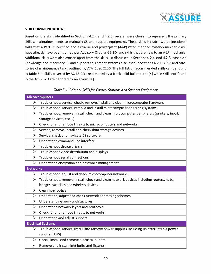
20
5 RECOMMENDATIONS
Based on the skills identified in Sections 4.2.4 and 4.2.5, several were chosen to represent the primary skills a maintainer needs to maintain CS and support equipment. These skills include two delineations: skills that a Part 65 certified and airframe and powerplant (A&P) rated manned aviation mechanic will have already have been trained per Advisory Circular 65-2D, and skills that are new to an A&P mechanic. Additional skills were also chosen apart from the skills list discussed in Sections 4.2.4 and 4.2.5 based on knowledge about primary CS and support equipment systems discussed in Sections 4.2.1, 4.2.2 and cate-gories of maintenance tasks outlined by ATA iSpec 2200. The full list of recommended skills can be found in Table 5-1. Skills covered by AC 65-2D are denoted by a black solid bullet point [•] while skills not found in the AC 65-2D are denoted by an arrow [].
Table 5-1 Primary Skills for Control Stations and Support Equipment
Microcomputers Troubleshoot, service, check, remove, install and clean microcomputer hardware Troubleshoot, service, remove and install microcomputer operating systems Troubleshoot, remove, install, check and clean microcomputer peripherals (printers, input,
storage devices, etc….) Check for and remove threats to microcomputers and networks Service, remove, install and check data storage devices Service, check and navigate CS software Understand command line interface Troubleshoot device drivers Troubleshoot video distribution and displays Troubleshoot serial connections Understand encryption and password management
Networks Troubleshoot, adjust and check microcomputer networks Troubleshoot, remove, install, check and clean network devices including routers, hubs,
bridges, switches and wireless devices Clean fiber optics Understand, adjust and check network addressing schemes Understand network architectures Understand network layers and protocols Check for and remove threats to networks Understand and adjust subnets
Electrical Systems Troubleshoot, service, install and remove power supplies including uninterruptable power
supplies (UPS) Check, install and remove electrical outlets • Remove and install light bulbs and fixtures

21
• Understand wiring diagrams • Understand the effect of environmental factors on electrical systems • Check, install and remove circuit protection devices including fuses, breakers, cooling systems
and voltage/amperage regulators • Understand Electromagnetic Interference (EMI) and methods of protecting against EMI in-
cluding shielding • Service, remove, install and check batteries including lithium chemistries • Understand AC/DC terminology • Understand basic circuit operation • Troubleshoot electrical circuits • Calculate AC/DC circuit values • Check circuits using measurement devices including ammeters, ohmmeters, oscilloscopes and
voltmeters • Understand resistor color codes and markings • Understand resistors, inductors, capacitors, transformers, diodes, transistors and oscillators • Troubleshoot resistors, inductors, capacitors and transformers • Troubleshoot, service, install and remove analog circuit devices and switches • Understand rectifiers and inverters • Understand digital logic functions and components • Identify types of wiring and cabling • Service, remove, install, inspect, and repair wiring and connectors • Understand safe handling for electrostatic sensitive (ESD) components
General - Control station • Service, remove, install, and check intercommunication systems Understand maintenance terminals Understand CS system power up, power down, reboot and emergency procedures Understand scheduled and operational CS inspections Service CS data logs Test CS using self-test features Understand CS "Safe for Maintenance" procedures Clean CS workstations Understand CS signal flow and relationship of systems Install and remove workstation seats Adjust and check CS ground sensors including GPS and atmospheric sensors
Pneumatic and Hydraulic Catapult Launchers Understands aircraft launch theory Understand calculation of launch values including end of catapult velocity and launch force • Service, inspect and check hydraulic and pneumatic power systems • Remove, install, inspect and repair fluid and gas lines and fittings
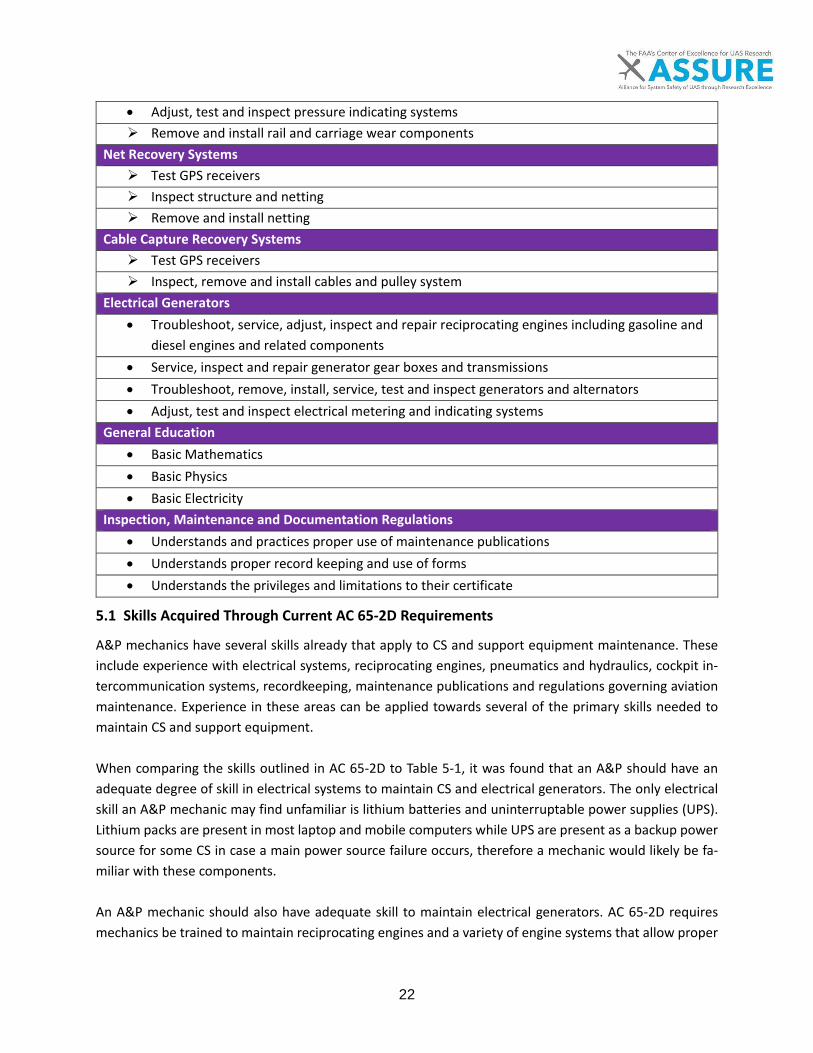
22
• Adjust, test and inspect pressure indicating systems Remove and install rail and carriage wear components
Net Recovery Systems Test GPS receivers Inspect structure and netting Remove and install netting
Cable Capture Recovery Systems Test GPS receivers Inspect, remove and install cables and pulley system
Electrical Generators • Troubleshoot, service, adjust, inspect and repair reciprocating engines including gasoline and
diesel engines and related components • Service, inspect and repair generator gear boxes and transmissions • Troubleshoot, remove, install, service, test and inspect generators and alternators • Adjust, test and inspect electrical metering and indicating systems
General Education • Basic Mathematics • Basic Physics • Basic Electricity
Inspection, Maintenance and Documentation Regulations • Understands and practices proper use of maintenance publications • Understands proper record keeping and use of forms • Understands the privileges and limitations to their certificate
5.1 Skills Acquired Through Current AC 65-2D Requirements
A&P mechanics have several skills already that apply to CS and support equipment maintenance. These include experience with electrical systems, reciprocating engines, pneumatics and hydraulics, cockpit in-tercommunication systems, recordkeeping, maintenance publications and regulations governing aviation maintenance. Experience in these areas can be applied towards several of the primary skills needed to maintain CS and support equipment. When comparing the skills outlined in AC 65-2D to Table 5-1, it was found that an A&P should have an adequate degree of skill in electrical systems to maintain CS and electrical generators. The only electrical skill an A&P mechanic may find unfamiliar is lithium batteries and uninterruptable power supplies (UPS). Lithium packs are present in most laptop and mobile computers while UPS are present as a backup power source for some CS in case a main power source failure occurs, therefore a mechanic would likely be fa-miliar with these components. An A&P mechanic should also have adequate skill to maintain electrical generators. AC 65-2D requires mechanics be trained to maintain reciprocating engines and a variety of engine systems that allow proper

23
operation. The knowledge and training acquired around reciprocating engines can be used to maintain the engine that powers the generator. The generator motor or alternator inside the generator, as well as indi-cating and metering components of a generator, should also be familiar to an A&P as alternators and gen-erator motors are used to power the electrical systems onboard most general aviation aircraft. The skillset of an A&P mechanic should also contain skills relevant to pneumatic and hydraulic launchers. AC 65-2D includes a requirement for knowledge on pneumatic and hydraulic power systems and fluid lines and fittings, both of which could be applied to pneumatic and hydraulic launchers. The only aspect of the launchers missing would be skills related to replacing wear parts on the rail and carriage and the high importance and safety required for support equipment during operations.
Other skill areas an A&P has that applies to maintenance of CS and support equipment includes knowledge of the records, forms and logbooks required to be kept for certified aircraft and education in basic physics, electricity and mathematics. An A&P has a starting set of skills that can help them maintain CS and support equipment, however additional skills are required to familiarize the mechanic with the components and systems in CS and support equipment.
5.2 Skills Not Found in AC 65-2D
The largest gaps in an A&P mechanics skillset are related to microcomputers, networks and skills specific to only CS. Support equipment have much smaller gaps, as most A&P mechanics will not be familiar with net and cable capture recovery systems. These gaps make up the skills recommended for an A&P mechanic to acquire prior to maintaining CS and support equipment. To see a full list of the primary skillset a main-tainer needs to maintain CS and support equipment please see Table 5-1.
While an A&P mechanic meeting the required skill of AC 65-2D will have knowledge and training in elec-tricity, microcomputers are not mentioned once. The skills required to maintain microcomputers as part of a CS include the ability to maintain hardware, operating systems, peripheral devices and find and fix faults in security and connections to outside devices including display monitors. Knowledge and the ability to maintain microcomputers is critical to the CS as a single or network is used to process incoming and outgoing data and provide an interface for the operator to send control inputs and commands and to view data. Mistakes during maintenance or neglect of microcomputer components have the potential to lead to hidden, latent failures and intermittent problems.
If the CS’s microcomputer(s) require connection to other devices or outside networks, an A&P mechanic would need training to maintain computer networks as AC 65-2D does not require any skill related to networks. An A&P would need to acquire additional skill in regards to the maintenance of networks of an entire system, network devices, fiber optics, network addresses, network layers and protocols, network security and other topics under “Networks” in Table 5-1. The ability to maintain computer networks is critical to ensuring safe and reliable operation of some UAS as the aircraft and CS often send pilot input, aircraft status and data, and payload data as part of a network.

24
If there are multiple computers in a CS, a network should be in place to allow these computers to com-municate while they conduct separate tasks such as interfacing as a pilot or sensor operator workstation or a communications interface. Therefore, if maintenance is not conducted correctly, networks could be open to external threats and faults that prevent proper operation of the CS.
A handful of skills that apply specifically to CS were also identified as a gap in A&P training, as AC 65-2D was not written with unmanned aviation in mind and CS are unique to UAS. The majority of these skills are operational and procedural functions a maintainer would need to conduct. This includes operational procedures, scheduled inspections of the CS, managing system logs, preparing the CS for safe mainte-nance, cleaning the CS and understanding how to separate components of the CS relate to each other. Having experience in these areas would help introduce the maintainer to typical maintenance tasks and procedures conducted on CS as well as the system itself.
Regarding pneumatic and hydraulic launchers, an A&P mechanic would require little additional training to maintain these items. Hydraulic and pneumatic systems will already be familiar to an A&P mechanic but other aspects would require further skill. Understanding of how launch systems work and understanding of how to calculate expected performance to test launch systems would be required along with the ability to service and replace wear components on launcher rails and carriages. Proper maintenance of these launch systems will prevent hazardous situations and damage to the UA.
Additional variations in launch and recovery systems exist, but catapults contain the most significant num-ber of UAS models and no data was found on other varieties of support equipment discussed in Section 4.1. Additional skills may be required as UAS technology evolves and trends in the industry change.
5.3 Conclusions
Control station (CS) and support equipment add many unique maintenance elements that are different from manned aircraft. One of the particularly unique aspects of CS is the sub-components that make up the system. Compared to traditional aviation, consumer electronics and microcomputers are dependent to provide the pilot interface. Microcomputers create a need for computer networks that are unfamiliar to manned aviation. The presence of these components in CS and the lack of training an A&P mechanic has in these areas, creates a requirement for mechanics to be trained in the areas identified in Table 5-1.
Along with the skills and knowledge an A&P mechanic may not be familiar with, CS and support equipment present unique aspects to maintenance. Though physically separate, CS and support equipment are part of the complete unmanned aircraft system and must be maintained as such. Testing and checking the UAS will sometimes require utilization of multiple separate parts of the system or the use of special tools. The way components of the UAS wear will differ greatly as the environment the CS, support equipment and UA are exposed to can differ greatly. This creates a need, not only for training in the skills needed to main-tain CS and support equipment, but also familiarization for mechanics to understand an unmanned aircraft system as a complete system with separate pieces to maintain the entire system effectively.

25

26
6 REFERENCES
[1] ASTM F2909-14, Standard Practice for Maintenance and Continued Airworthiness of Small Un-
manned Aircraft Systems (sUAS), ASTM International, 2014.
[2] "Association for Unmanned Vehicle Systems International – UAS Platform Database," 2016.
[3] D. M. Marshall, R. K. Barnhart, E. Shappee and M. Most, Introduction to Unmanned Aircraft Systems
(2nd edition), Boca Raton: Taylor & Francis, CRC Press, 2016.
[4] A. Hobbs and S. R. Herwitz, Human Challenges in the Maintenance of Unmanned Aircraft Systems,
FAA and NASA Report, 2006.
[5] A. &. S. R. J. Hobbs, Human Factor Challenges of Remotely Piloted Aircraft Available at http://human-
factors. arc. nasa. gov/publications/Hobbs_EAAP. pdf., NASA, 2014.
[6] A. &. H. Hobbs, Human Factors in the Maintenance of Unmanned Aircraft. Small, 15(100), 2014.
[7] A. &. H. Hobbs, Maintenance Challenges of Small Unmanned Aircraft Systems - A Human Factors
Perspective. doi:10.13140/RG.2.1.1858.8647, 2008.
[8] "U.S. Air Force Fact Sheets @ http://www.af.mil/AboutUs/FactSheets.aspx," [Online].
[9] "U.S. Army Unmanned Aircraft Systems Repairer (15E) (n.b.) career profile," [Online]. Available:
http://www.goarmy.com/careers-and-jobs/browse-career-and-job-categories/transportation-and-
aviation/unmanned-aircraft-systems-repairer.html. [Accessed 04 April 2017].
[10] "U.S. Army Unmanned Aircraft Systems Operator (15W) (n.d.) career profile," [Online]. Available:
http://www.goarmy.com/careers-and-jobs/browse-career-and-job-categories/transportation-and-
aviation/unmanned-aerial-vehicle-operator.html. [Accessed 04 April 2017].
[11] "U.S. Air Force Remotely Piloted Aircraft Maintenance career profile @
https://www.airforce.com/careers/detail/remotely-piloted-aircraft-maintenance," [Online].
[12] "U.S. Marines MOS 6314 Avionics/Maintenance Technician, Unmanned Aircraft System (UAS) career
profile," [Online]. Available: http://www.cool.navy.mil/usmc/enlisted/6314.htm. [Accessed 04 April
2017].
[13] U. T. Force, The Joint JAA/EUROCONTROL Initiative on UAVs. UAV Task Force Final Report., 2004.
[14] Northland Community and Technical College, Northland Aerospace- Modified Shelter Task List, 2017.

27
[15] A. Andrews, J. Beck, T. J. Beckman, T. Biller, D. A. Fischer, D. Jones, S. C. Ley, Z. Nicklin, T. Thornton, C.
T. Volinkaty and B. Webb, "DACUM Research Chart for UAS Maintenance Technician," Northland
Community Technical College and Northland Aerospace, 2016.
[16] Aircraft Electronics Technician (AET) Standard, National Center for Aerospace and Transportation
Technologies, 2009.
[17] Airlines for America. iSpec 2200: Information Standards for Aviation Maintenance., 2016.
[18] Airmen other than Flight Crew Members, 14 C.F.R. pt. 65, 2011.
[19] "Remotely Piloted Aircraft Maintenance. (n.d.)," [Online]. Available:
https://www.airforce.com/careers/detail/remotely-piloted-aircraft-maintenance. [Accessed 04
April 2017].
[20] "RQ-4 Global Hawk. (2014, October 27).," [Online]. Available:
http://www.af.mil/AboutUs/FactSheets/Display/tabid/224/Article/104516/rq-4-global-hawk.aspx.
[Accessed 27 February 2017].
[21] N. C. f. A. a. T. Technologies, Unmanned Aircraft System (UAS) Maintenance Standard, 2012.
[22] "333COA CS and Comm Incident Acccident Database," Kansas State University, Applied Aviation
Research Center., 2017.
[23] "Maintenance and Repair Database.," Kansas State University, Applied Aviation Research Center,
2016.
[24] K. Barnhart, S. Ley, T. Bruner, M. Most and A. Meyer, "Draft Technical Report of UAS Maintenance
Data Preliminary Analysis," Kansas State University, Manhattan, 2016.
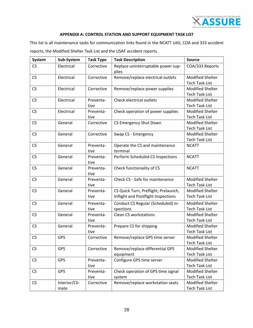
28
APPENDIX A: CONTROL STATION AND SUPPORT EQUIPMENT TASK LIST
This list is all maintenance tasks for communication links found in the NCATT UAS, COA and 333 accident
reports, the Modified Shelter Task List and the USAF accident reports.
System Sub-System Task Type Task Description Source CS Electrical Corrective Replace uninterruptable power sup-
plies COA/333 Reports
CS Electrical Corrective Remove/replace electrical outlets Modified Shelter Tech Task List
CS Electrical Corrective Remove/replace power supplies Modified Shelter Tech Task List
CS Electrical Preventa-tive
Check electrical outlets Modified Shelter Tech Task List
CS Electrical Preventa-tive
Check operation of power supplies Modified Shelter Tech Task List
CS General Corrective CS Emergency Shut Down Modified Shelter Tech Task List
CS General Corrective Swap CS - Emergency Modified Shelter Tech Task List
CS General Preventa-tive
Operate the CS and maintenance terminal
NCATT
CS General Preventa-tive
Perform Scheduled CS Inspections NCATT
CS General Preventa-tive
Check functionality of CS NCATT
CS General Preventa-tive
Check CS - Safe for maintenance Modified Shelter Tech Task List
CS General Preventa-tive
CS Quick Turn, Preflight, Prelaunch, Inflight and Postflight Inspections
Modified Shelter Tech Task List
CS General Preventa-tive
Conduct CS Regular (Scheduled) In-spections
Modified Shelter Tech Task List
CS General Preventa-tive
Clean CS workstations Modified Shelter Tech Task List
CS General Preventa-tive
Prepare CS for shipping Modified Shelter Tech Task List
CS GPS Corrective Remove/replace GPS time server Modified Shelter Tech Task List
CS GPS Corrective Remove/replace differential GPS equipment
Modified Shelter Tech Task List
CS GPS Preventa-tive
Configure GPS time server Modified Shelter Tech Task List
CS GPS Preventa-tive
Check operation of GPS time signal system
Modified Shelter Tech Task List
CS Interior/Cli-mate
Corrective Remove/replace workstation seats Modified Shelter Tech Task List
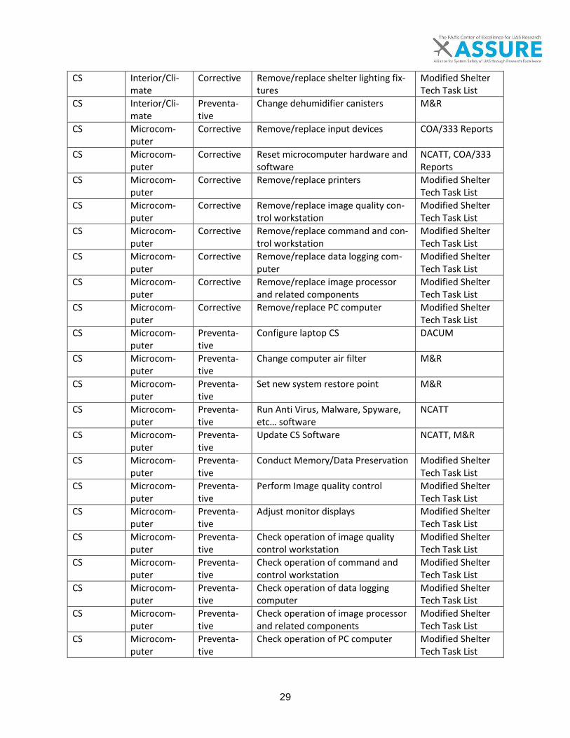
29
CS Interior/Cli-mate
Corrective Remove/replace shelter lighting fix-tures
Modified Shelter Tech Task List
CS Interior/Cli-mate
Preventa-tive
Change dehumidifier canisters M&R
CS Microcom-puter
Corrective Remove/replace input devices COA/333 Reports
CS Microcom-puter
Corrective Reset microcomputer hardware and software
NCATT, COA/333 Reports
CS Microcom-puter
Corrective Remove/replace printers Modified Shelter Tech Task List
CS Microcom-puter
Corrective Remove/replace image quality con-trol workstation
Modified Shelter Tech Task List
CS Microcom-puter
Corrective Remove/replace command and con-trol workstation
Modified Shelter Tech Task List
CS Microcom-puter
Corrective Remove/replace data logging com-puter
Modified Shelter Tech Task List
CS Microcom-puter
Corrective Remove/replace image processor and related components
Modified Shelter Tech Task List
CS Microcom-puter
Corrective Remove/replace PC computer Modified Shelter Tech Task List
CS Microcom-puter
Preventa-tive
Configure laptop CS DACUM
CS Microcom-puter
Preventa-tive
Change computer air filter M&R
CS Microcom-puter
Preventa-tive
Set new system restore point M&R
CS Microcom-puter
Preventa-tive
Run Anti Virus, Malware, Spyware, etc… software
NCATT
CS Microcom-puter
Preventa-tive
Update CS Software NCATT, M&R
CS Microcom-puter
Preventa-tive
Conduct Memory/Data Preservation Modified Shelter Tech Task List
CS Microcom-puter
Preventa-tive
Perform Image quality control Modified Shelter Tech Task List
CS Microcom-puter
Preventa-tive
Adjust monitor displays Modified Shelter Tech Task List
CS Microcom-puter
Preventa-tive
Check operation of image quality control workstation
Modified Shelter Tech Task List
CS Microcom-puter
Preventa-tive
Check operation of command and control workstation
Modified Shelter Tech Task List
CS Microcom-puter
Preventa-tive
Check operation of data logging computer
Modified Shelter Tech Task List
CS Microcom-puter
Preventa-tive
Check operation of image processor and related components
Modified Shelter Tech Task List
CS Microcom-puter
Preventa-tive
Check operation of PC computer Modified Shelter Tech Task List

30
CS Microcom-puter/Net-work
Preventa-tive
Manage Security Measures (pass-words, identity, etc…)
NCATT
CS Network Corrective Network Fault Isolation and Trouble-shooting
NCATT
CS Network Corrective Remove/replace network devices Modified Shelter Tech Task List
CS Network Preventa-tive
Configure network devices Modified Shelter Tech Task List
CS Network Preventa-tive
Check operation of network devices Modified Shelter Tech Task List
CS Network Preventa-tive
Check operation of patch panel Modified Shelter Tech Task List
CS Network Preventa-tive
Clean fiber optics Modified Shelter Tech Task List
CS Software Preventa-tive
Load Mission Plans and Maps Modified Shelter Tech Task List
CS Software Preventa-tive
Load and Save UAV configuration files in CS
Modified Shelter Tech Task List
CS Voice Com-munications
Corrective Remove/replace intercommunica-tion devices (headsets, switches, etc…)
Modified Shelter Tech Task List
CS Voice Com-munications
Corrective Remove/replace communications workstation
Modified Shelter Tech Task List
CS Voice Com-munications
Preventa-tive
Configure intercommunication sys-tem
Modified Shelter Tech Task List
CS Voice Com-munications
Preventa-tive
Update Intercommunication soft-ware
Modified Shelter Tech Task List
CS Voice Com-munications
Preventa-tive
Check operation of communications workstations
Modified Shelter Tech Task List
CS/Comm Electrical Corrective Isolate faulty resistors, inductors, ca-pacitors, transformers
NCATT
CS/Comm Electrical Corrective Troubleshoot electrical circuits NCATT CS/Comm Electrical Corrective Install and Corrective wiring and
connections NCATT
CS/Comm Electrical Preventa-tive
Inspect wiring NCATT
CS/Comm General Preventa-tive
Conduct system self-tests Modified Shelter Tech Task List
SE Arresting Gear
Corrective Replace arresting cable COA/333 Reports
SE Cable Cap-ture
Preventa-tive
Inspect cable capture recovery com-ponents
M&R
SE Cable Cap-ture
Preventa-tive
Replace cable capture recovery components
M&R
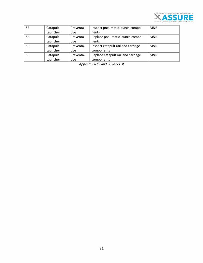
31
SE Catapult Launcher
Preventa-tive
Inspect pneumatic launch compo-nents
M&R
SE Catapult Launcher
Preventa-tive
Replace pneumatic launch compo-nents
M&R
SE Catapult Launcher
Preventa-tive
Inspect catapult rail and carriage components
M&R
SE Catapult Launcher
Preventa-tive
Replace catapult rail and carriage components
M&R
Appendix A CS and SE Task List

32
APPENDIX B: CONTROL STATION AND SUPPORT EQUIPMENT SKILLS LIST
A list of the skills indicated as needed to maintain UAS communication links by the NCATT UAS, the DACUM
Research Chart and the Appendix A task list.
CS SE Category Knowledge/Skill Description Source In AC 65-2D?
X Computer Funda-mentals
Computer Components NCATT, DACUM
N
X Central Processing Unit (CPU) NCATT N X Computer Memory NCATT N X Remove and replace input devices Task List N X Input/Output (I/O) Devices NCATT N X Storage Devices NCATT N X Peripherals Devices (Printers, FAX,
Scanners, etc) NCATT N
X Converters NCATT N X BIOS/UEFI verification DACUM N X Microcomputer maintenance DACUM N X Serial connections DACUM N X Remove and replace printers Task List N X Printer configuration DACUM N X Networks Addressing/naming schemes in data
networks DACUM N
X Broadband connections DACUM N X Dynamic host configuration protocol
(DHCP) DACUM N
X Ethernet networking DACUM N X Network address translation (NAT) DACUM N X Network architectures, configurations
& utilities DACUM N
X Protocol layers in data networks DACUM N X Subnetting DACUM N X Multiplexing / De-multiplexing NCATT N X Hubs NCATT N X IP Signal Flow / Data Transfer NCATT N X Long Haul Communication / WAN NCATT N X Processors NCATT N X Programming Languages NCATT N X Routers NCATT,
DACUM N
X Routing Protocols DACUM N
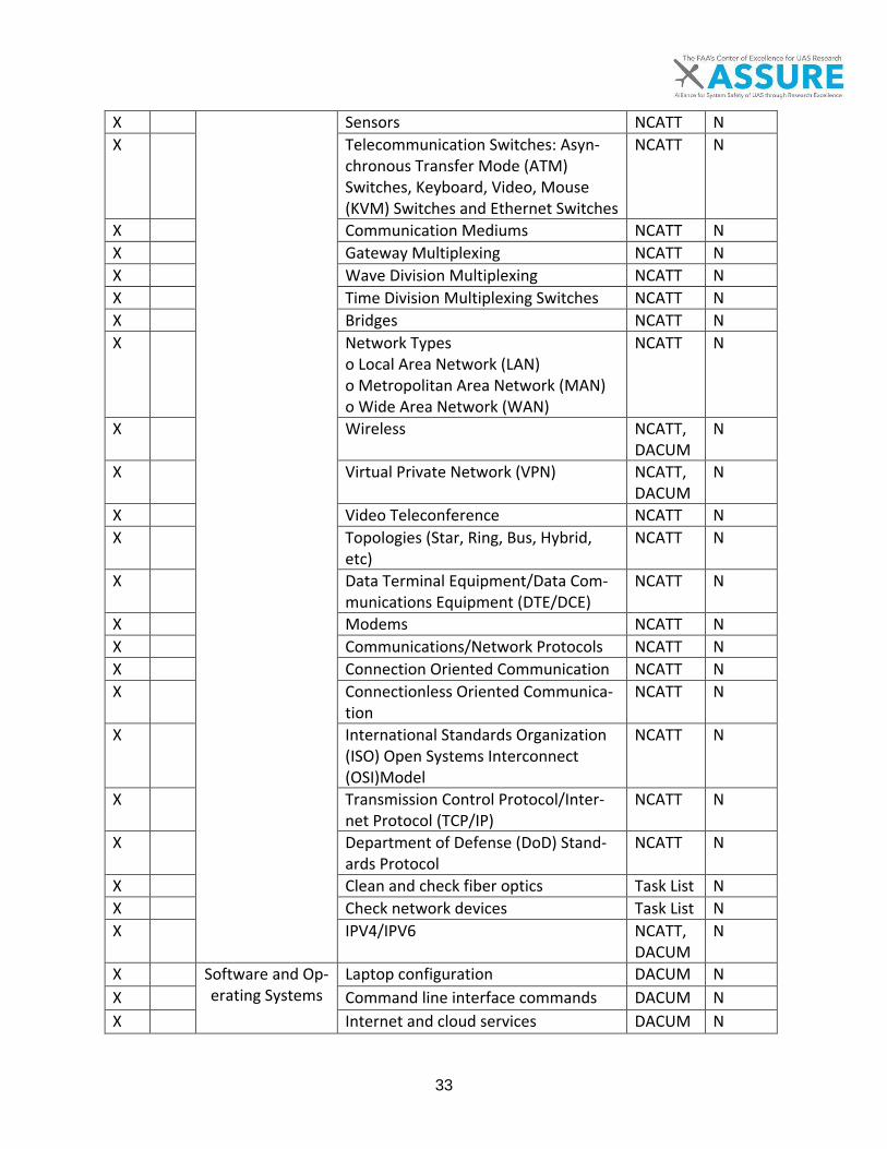
33
X Sensors NCATT N X Telecommunication Switches: Asyn-
chronous Transfer Mode (ATM) Switches, Keyboard, Video, Mouse (KVM) Switches and Ethernet Switches
NCATT N
X Communication Mediums NCATT N X Gateway Multiplexing NCATT N X Wave Division Multiplexing NCATT N X Time Division Multiplexing Switches NCATT N X Bridges NCATT N X Network Types
o Local Area Network (LAN) o Metropolitan Area Network (MAN) o Wide Area Network (WAN)
NCATT N
X Wireless NCATT, DACUM
N
X Virtual Private Network (VPN) NCATT, DACUM
N
X Video Teleconference NCATT N X Topologies (Star, Ring, Bus, Hybrid,
etc) NCATT N
X Data Terminal Equipment/Data Com-munications Equipment (DTE/DCE)
NCATT N
X Modems NCATT N X Communications/Network Protocols NCATT N X Connection Oriented Communication NCATT N X Connectionless Oriented Communica-
tion NCATT N
X International Standards Organization (ISO) Open Systems Interconnect (OSI)Model
NCATT N
X Transmission Control Protocol/Inter-net Protocol (TCP/IP)
NCATT N
X Department of Defense (DoD) Stand-ards Protocol
NCATT N
X Clean and check fiber optics Task List N X Check network devices Task List N X IPV4/IPV6 NCATT,
DACUM N
X Software and Op-erating Systems
Laptop configuration DACUM N X Command line interface commands DACUM N X Internet and cloud services DACUM N

34
X Data centers DACUM N X Database management DACUM N X Mobile device configuration DACUM N X Software licensing DACUM N X Virtualization DACUM N X Access control lists DACUM N X Configuration files DACUM N X CS Software NCATT N X Windows Operating Systems NCATT,
DACUM N
X Linux/UNIX operating Systems NCATT, DACUM
N
X OS X Operating Systems DACUM N X Applications (Word, Excel, Power
Point, Share Point, etc.) NCATT N
X Cryptology Bulk Encryption NCATT N X Information Encryption Techniques NCATT N X Encryption/COMSEC Devices (Data
and Voice) NCATT N
X Separation Requirements NCATT N X Network Fault
Isolation Network Error Detection NCATT N
X Network Error Correction NCATT N X Network Flow Control NCATT N X Transmission Impairments NCATT N X Network Man-
agement Con-cepts and Re-sponsibilities
Strategies, NCATT N X Networking Components, NCATT N X Configuration of Client/Server Compo-
nents and Infrastructure Components NCATT N
X Computer and Network Security
Cyber Vulnerabilities NCATT N X Vulnerability Preventative Measures NCATT N X Identity Management NCATT N X Infectious and Malicious Software NCATT N X Preserve and backup data Task List N X Network Security NCATT,
DACUM N
X Communications and Information
Professionals
Organizations NCATT N X Communications Competencies NCATT N X Expeditionary Communications NCATT N X Non-secure Internet Protocol Router
Network (NIPRNET) NCATT N

35
X Defense Infor-mation Systems Network (DISN)
Secure Networks NCATT N X Secret Internet Protocol Router Net-
work (SIPRNET) NCATT N
X Control station Electrical
Ground Generators NCATT N X Engine cooling systems DACUM Y X Engine electrical systems DACUM Y X Engine exhaust and reverser systems DACUM Y X Engine fuel systems DACUM Y X Engine inspection DACUM Y X Engine instrument systems DACUM Y X Fuel metering systems DACUM Y X Ignition and starting systems DACUM Y X Induction and engine airflow systems DACUM Y X Lubrication systems DACUM Y X Reciprocating engines DACUM Y X Ground Power Unit (GPU) NCATT N
X Uninterrupted Power Source (UPS) NCATT N X Check, remove and replace electrical
outlets Task List N
X Control station Voice Communi-
cations
Check, remove and replace communi-cations workstation
Task List N
X Update intercommunication system software
Task List N
X Remove, install, configure and check intercommunication devices
Task List Y
X Maintenance Terminals
Types NCATT N X Set-up NCATT N X Power Up/Down NCATT N X Ground Station
Maintenance Rack Reset (Soft vs. Hard Reboot) NCATT N
X Software Use/Manipulation NCATT N X UA Control NCATT N X Data Logger Download (i.e blackbox) NCATT N X Software Upload NCATT N X Preflight Inspections NCATT N X Postflight Inspections NCATT N X Scheduled Inspections NCATT N X Signal Flow NCATT N X CS safe for maintenance procedures Task List N X Clean workstations Task List N
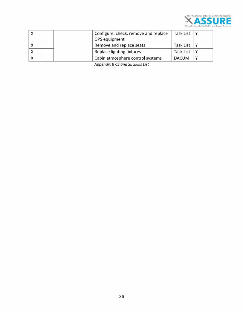
36
X Configure, check, remove and replace GPS equipment
Task List Y
X Remove and replace seats Task List Y X Replace lighting fixtures Task List Y X Cabin atmosphere control systems DACUM Y
Appendix B CS and SE Skills List
A.5 UAS Maintenance, Modification, Repair,Inspection, Training, and CertificationConsiderations
TASK 4C: DEVELOP MAINTENANCE TECHNICIAN TRAINING REQUIREMENTS:
In-Depth Analysis of Areas that Require Special Considerations
I. Non-Metallic material structuresII. Ground control stations and support equipment
III. Communication linksIV. Software and autopilots

ii
NOTICE
This document is disseminated under the sponsorship of the U.S. Department of Transportation in the interest of information exchange. The U.S. Government assumes no liability for the contents or use thereof. The U.S. Government does not endorse products or manufacturers. Trade or manufacturers’ names appear herein solely because they are considered essential to the objective of this report. The findings and conclusions in this report are those of the author(s) and do not necessarily represent the views of the funding agency. This document does not constitute FAA policy. Consult the FAA sponsoring organization listed on the Technical Documentation page as to its use.

iii
Legal Disclaimer: The FAA has sponsored this project through the Center of Excellence for Unmanned Aircraft Systems. However, the agency neither endorses nor rejects the findings of this research. The presentation of this information is in the interest of invoking technical com-ment on the results and conclusions of the research.

iv
Technical Report Documentation Page
Title: .5 UAS Maintenance, Modification, Repair, Inspection, Training, and Certification Considerations Non-metallic materials
Report Date: 6 November 2017
Performing Organizations: Kansas State University (KSU)
Authors: Dr. Kurt Barnhart, Charles Nick, Andrea Meyer, Caleb Scott, Nathan Maresch
Performing Organization Address: Kansas State University Sponsored Programs 2323 Anderson Ave, Suite 600 Manhattan, KS 66502
Sponsoring Agency Name and Address: U.S. Department of Transportation Federal Aviation Administration Washington, DC 20591

v
TABLE OF CONTENTS PAGE
1 EXECUTIVE SUMMARY .......................................................................................................... 1
2 SCOPE ................................................................................................................................... 2
3 INTRODUCTION .................................................................................................................... 3
4 IN-DEPTH ANALYSIS .............................................................................................................. 4
4.1 LITERATURE REVIEW .................................................................................................................... 4 4.2 CURRENT MAINTENANCE PRACTICES FOR COMMUNICATION SYSTEMS ................................................... 9
5 RECOMMENDATIONS .......................................................................................................... 14
5.1 SKILLS ACQUIRED THROUGH CURRENT AC 65-2D REQUIREMENTS .................................................... 15 5.2 SKILLS NOT FOUND IN AC 65-2D ................................................................................................ 16 5.3 CONCLUSIONS .......................................................................................................................... 17
6 REFERENCES ........................................................................................................................ 18

vi
LIST OF FIGURES Figures Page
FIGURE 4-1. COMMUNICATION LINK ELEMENTS ............................................................................ 5 FIGURE 4-2. COMMUNICATION LINK CONFIGURATIONS ............................................................. 10
LIST OF TABLES Tables Page TABLE 2-1. A5 WORK BREAKDOWN STRUCTURE 2 TABLE 4-1. PRIMARY COMMUNICATION LINK COMPONENTS 9 TABLE 5-1. PRIMARY SKILLS 14
1
1 EXECUTIVE SUMMARY
A review of literature was conducted to determine the unique aspects of maintaining unmanned aircraft system communication links. It was found that communication links could be broken down into four cate-gories: command and control links, telemetry links, payload links and voice communications. The four cat-egories were all found to have components both on the surface and in the air, allowing the operator to control the unmanned aircraft and gain situational awareness without leaving the ground. This physical separation of components of the communication link system was found to be one of the most unique aspects of maintaining communication links as components in the UA and on the ground experience dif-ferent environmental conditions and are required to be maintained and tested as a system despite being separate. Components in the air and on the ground, though identical may wear at different rates causing different schedules of maintenance for each. When troubleshooting is required or a scheduled mainte-nance task occurs, checking and testing different parts of the communication link system sometimes re-quire that both the UA and ground components be tested cooperatively to ensure proper operation or isolate faults.
In addition to unique aspects of communication link maintenance, sources of information were reviewed including industry standards and maintenance tasks currently conducted on communication links to de-termine what skill a maintainer needs to maintain communication links. It was found that an A&P me-chanic would have most of the skills required to maintain communication links including skill with electrical systems, voice and navigation radios, antennas and practices and procedures for conducting maintenance on a certified aircraft. However, an A&P mechanic would also need to be trained on troubleshooting and testing UAS communication links, maintaining antenna tracking equipment and satellite communication links.

2
2 SCOPE
The scope of this document is defined in Task 4c(iii) as highlighted in Table 2-1 below: The in-depth analysis for Communication Links. Other subtasks in Task 4 are not shown for clarity.
Table 2-1. A5 Work Breakdown Structure
Task Description Team
Task 1 Review of Existing Maintenance Programs and Data KSU, ERAU
Task 2 Update Maintenance and Repair Prototype Database KSU
Task 3 Review of Maintenance Technician Training NCTC
Task 4 Update Maintenance and Repair Prototype Database KSU
Task 4a Review manned maintenance technician regulations, standards and best prac-tices
NCTC
Task 4b Gap analysis of manned versus unmanned maintenance technician tasks NCTC
Task 4c In-depth analysis of areas that require special considerations KSU, ERAU MTSU NCTC
Task 4c(i) Non-metallic Material Structures MTSU
Task 4c(ii) Control stations and support equipment KSU
Task 4c(iii) Communication Links KSU
Task 4c(iv) Software & Autopilots ERAU
Task 4d Gap analysis of manned versus unmanned maintenance technician tasks KSU
Deliverable Draft technical report of UAS maintenance technician training criteria and draft cer-tification requirements
KSU
Task 5 Conduct Simulations Focused on UAS-ATC Procedures ERAU
Task 6 Support UAS Certification Efforts and recommendations for ASI training and repair stations
KSU, ERAU
Task 7 Examine Requirements for Maintenance-related Accident Reporting ERAU
Task 8 Final Report KSU

3
3 INTRODUCTION
One of the goals of Task 4 of the A.5 project is to determine where current manned aviation standards meet the requirements to maintain unmanned aircraft systems (UAS) and where new requirements and skill must be developed for UAS maintainers. Four major areas were identified at the beginning of the project that were new and unique compared to manned aviation. These areas include non-metallic mate-rial structures, control stations and support equipment, communication links, and software and autopilots. This report focuses on unmanned aircraft communication links. UAS contain several physically separate sub-systems working together to create one system to perform flight operations. The element of UAS that provides integration between the sub-systems is the commu-nication link, which allows the operator to send and receive commands and data from an interface physi-cally separate of the unmanned aircraft. As a result, the communication link is unique the element is lo-cated on the Unmanned Aircraft (UA) and control station (CS). The roles communication links perform connect the operator on the ground to the flight controls located on the UA in the air; therefore the maintenance of the communication link system can be as critical as the UA itself. Though 14 CFR Part 65 certified maintainers have a diverse set of skills, additional training, knowledge and skills are required to complete the maintenance tasks of communication links.
4
4 IN-DEPTH ANALYSIS
The in-depth analysis reviewed relevant literature and current maintenance practices in the UAS industry
today. Since this industry is relatively new a smaller amount of sources were discovered than normal, but
this was sufficient for creating initial taxonomies for communication links.
4.1 Literature Review
To gather a base of knowledge on communication links, identified sources of information were reviewed for data, facts and discussion relevant to communication link maintenance. The following sources were reviewed for context and findings related to communication links:
• ASTM D2909-14 Standard Practice for Maintenance and Continued Airworthiness of Small Un-manned Aircraft Systems (sUAS) [1]
• ASTM F3002-14 Standard Specification for Design of the Command and Control System for SmallUnmanned Aircraft Systems (sUAS) [2]
• AUVSI – UAS Platform Database [3]• Introduction to Unmanned Aircraft Systems (2nd edition) by Marshall, D. M., Barnhart, R. K., Shap-
pee, E., & Most, M. [4]• Human Challenges in the Maintenance of Unmanned Aircraft Systems by Hobbs, A., & Herwitz [5]• Human Factor Challenges of Remotely Piloted Aircraft by Hobbs, A., & Shively, R. J. [6]• Human Factors in the Maintenance of Unmanned Aircraft by Hobbs, A., & Herwitz [7]• Maintenance Challenges of Small Unmanned Aircraft Systems - A Human Factors Perspective by
Hobbs, A., & Herwitz [8]• U.S. Air Force Fact Sheets [9]• U.S. Army Unmanned Aircraft Systems Repairer (15E) career profile [10]• U.S. Army Unmanned Aircraft Systems Operator (15W) career profile [11]• U.S. Air Force Remotely Piloted Aircraft Maintenance career profile [12]• U.S. Marines MOS 6314 Avionics/Maintenance Technician, Unmanned Aircraft System (UAS) ca-
reer profile [13]
After reviewing these sources, discussion areas including the individual data elements transmitted through communication links, flight criticality of communication links, components that can make up communica-tion link equipment and unique maintenance considerations were observed. As the means to allow sepa-ration of the operator and Unmanned Aircraft (UA), UAS communication links were found to carry infor-mation and functionality normally housed within the cockpit of manned aircraft.

5
4.1.1 Communication Link Elements
In an unmanned aircraft system (UAS), the communication link allows the operator to pilot the unmanned aircraft while being separated from the UA by transferring pilot inputs in radio waves instead of physical connections used in manned aircraft. This requires the communication link system to be installed on both the control station and onboard the UA. The communication link system provides four purposes critical to the operation of a UAS. These purposes make up the four data elements of a communication link system include the following [6] ( p.3):
1. Uplink command/control 2. Downlink telemetry 3. Voice communications 4. Payload link
See Figure 4-1. Communication Link Elements for more information on these data elements.
Figure 4-1. Communication Link Elements
Uplink Command and Control
Transfers operator inputs and com-mands from the ground to the UA.
Downlink Teleme-try
Transfers flight data and aircraft status to the ground.
Voice Communica-tions
Allows the operator to transmit and receive vocal communications between the control station and air traffic control or other aircraft op-erations. In some cases the aircraft acts as a relay between the CS and air traffic control.

6
Payload Link Transfers data gather by the UA’s payload to the ground.
Uplink command and control sends inputs from the operator to the unmanned aircraft and payload. Downlink telemetry confirms uplink commands and transmits the status of the UA back to the control station (CS). Voice communications transmit and receive verbal communications between the CS, opera-tors of other aircraft and Air Traffic Control (ATC). The payload link transmits photos, video or other data from the UA’s payload to the ground.
4.1.2 Variable Flight Criticality of Communication Link Data Elements
Communication systems in manned aviation are traditionally not used as a primary flight system but rather for gathering situational awareness through voice communications and navigation radios. Unmanned sys-tems differ from this tradition by using communication links as the only method of controlling the un-manned aircraft. This key difference categorized the communication system in a UAS as a flight critical system. In order to determine the flight criticality of the four communication link elements, their purposes and the consequences of system failure must be examined.
The lesser state of failure in a communication link system is known as a link error. Link error is a degrada-tion of the digital signal between the CS and UA (ASTM International, 2014b) [2]. If an acceptable rate of communication is occurring without any discernable errors, the link is known to have integrity (ASTM In-ternational, 2014b). If a link degrades beyond an acceptable rate of loss, then the operator can lose posi-tive control of the unmanned aircraft and the UA will be considered to have lost link, which is a complete severance of the link (ASTM International, 2014b). These two failure modes can cause loss of the UA if the link that is lost is the command and control uplink.

7
4.1.2.1 Command and Control Uplink (C2)
The command and control (C2) link is particularly important as it allows the pilot to control the UA both manually and through a set of commands for the autopilot to follow. When link error or a lost link is pre-sent in the C2 link, a fly-away can occur. A fly-away is a situation in which the UA operates outside of its altitude, airspeed and/or lateral boundaries as a result of a lost link (ASTM International, 2014b). However, if the UA has fly-away protection built in, then it can return itself to the surface or fly within programmed boundaries when the command and control uplink is lost (ASTM International, 2014b). Fly-away protection is imperative because the C2 link cannot be fully relied upon due to factors such as interference or jam-ming, which cannot be considered maintenance induced [6] (p.3). Unfortunately, fly-away protection var-ies by design and the UA may not be designed to avoid other air traffic, obstacles or areas that are not safe to fly over. Thus, fly-away protection is not a substitute for the operator’s control of their UA. If a link is degraded but not fully lost, the operator may experience delays in control inputs and feedback. While delays of 1 second or more are normal for UAS utilizing satellite links, link delay can hinder the performance of the operator as well as the system [14] (p. 144). Though the C2 link is critical for flight of the UAS, loss or degradation of other links can have adverse effects on the operation as well, like TBD and TBD.
4.1.2.2 Flight Criticality of Links Other Than C2
While the C2 link transfers pilot inputs, telemetry downlinks and payload links provide situational aware-ness and feedback from the UA to the operator. These two links are an example of links with similar pur-poses as both provide feedback and situational awareness to the operator. If either links are lost, situa-tional awareness will degrade but the other link will act as a failsafe. If both the telemetry and payload links are lost, situational awareness would be lost entirely. In the event the payload link is lost; the operator could also lose a level of situational awareness if the payload is used to aid in terrain and obstacle avoid-ance. Voice communications also provides situational awareness but only for air traffic and other hazards that ATC can provide alerts about. If a voice communications link is lost, the operator would be unable to listen to or respond to communications from other aircraft or Air Traffic Control without other forms of com-municating such as a telephone. Delays or latency in the voice communication link can also be problematic as delays of 750 milliseconds or more were found to disrupt communications between ATC and pilots [15].
8
4.1.2.3 Summary of Flight Criticality of Communication Links
While maintenance of communication link components cannot prevent loss of link in abnormal situations such as jamming and atmospheric interference, it can prevent link degradation or loss of link during normal operations and the consequences that follow. Degraded or lost communication on an unmanned aircraft has substantially greater consequences than a similar loss on a manned aircraft as communication links provide pilot input to the aircraft, aircraft feedback and situational awareness for the operator. For these reasons, the maintenance of the communication links in a UAS is critical [5] .
4.1.3 Unique Maintenance Considerations for UAS Communication Links
The primary difference of UAS from manned aviation is that the cockpit is on the ground requiring inputs and instrument readings are transmitted to and from the UA through a communication link. For this rea-son, a UAS must be maintained and inspected as parts in a system and not as a standalone aircraft [5] (p.10). This presents two factors: (1) the separation of ground and air link components; and (2) environ-mental factors that change how UAS can be maintained when compared to manned aircraft. Communication link components are located in the control station (CS) and the UA. This requires that some inspections or maintenance tasks be performed cooperatively between elements in the CS and the UA. Examples of these kinds of inspections could include testing link range, control input response and relay of voice communications [8] . In some cases, the UAS utilizes two separate control stations; the Launch and Recovery Element (LRE) and the Mission Control Element (MCE). The LRE is located within line of sight of the UA launch site and handles the initial and final stage of a mission while the MCE can be located anywhere in the world and handles the majority of the mission with the exception of launch and recovery. This is due to the LRE being limited to radio line of sight while the MCE utilizes satellite communications, which have greater latency than the line of sight links of the LRE [16]. Due to this type of operation, the MCE station may not be located near the UA which could limit the type of maintenance that can be conducted unless the CS and UA have the right equipment or self-testing features available. In addition to cooperative maintenance between the ground and air portions of a communication link system, the separation of ground and air components can also have environmental considerations. The conditions in which the UAS are exposed during operation and storage, such as wind, moisture and dust, are some of the environmental factors a UAS maintainer must consider. While the UAS is one system, the ground and air portions of the UAS will be exposed to different conditions [17] (p.72). Components located in the UA experience an environment similar to manned aircraft including temperature extremes, wind, moisture and vibration. However, components located on the ground experience environmental factors only present on the ground. This means that components located on the ground receive greater exposure to dirt and dust, but will not experience the same degree of vibration or wind as the UA. Exposure to dirt or dust is typically a concern for electronics that are part of the communication link system on the surface.
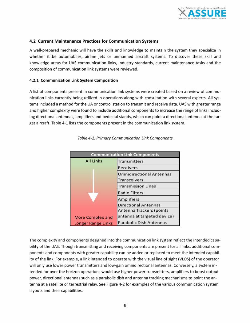
9
4.2 Current Maintenance Practices for Communication Systems
A well-prepared mechanic will have the skills and knowledge to maintain the system they specialize in whether it be automobiles, airline jets or unmanned aircraft systems. To discover these skill and knowledge areas for UAS communication links, industry standards, current maintenance tasks and the composition of communication link systems were reviewed.
4.2.1 Communication Link System Composition
A list of components present in communication link systems were created based on a review of commu-nication links currently being utilized in operations along with consultation with several experts. All sys-tems included a method for the UA or control station to transmit and receive data. UAS with greater range and higher complexity were found to include additional components to increase the range of links includ-ing directional antennas, amplifiers and pedestal stands, which can point a directional antenna at the tar-get aircraft. Table 4-1 lists the components present in the communication link system.
Table 4-1. Primary Communication Link Components
All Links TransmittersReceiversOmnidirectional AntennasTransceiversTransmission LinesRadio FiltersAmplifiersDirectional AntennasAntenna Trackers (points antenna at targeted device)Parabolic Dish Antennas
Communication Link Components
More Complex and Longer Range Links
The complexity and components designed into the communication link system reflect the intended capa-bility of the UAS. Though transmitting and receiving components are present for all links, additional com-ponents and components with greater capability can be added or replaced to meet the intended capabil-ity of the link. For example, a link intended to operate with the visual line of sight (VLOS) of the operator will only use lower power transmitters and low-gain omnidirectional antennas. Conversely, a system in-tended for over the horizon operations would use higher power transmitters, amplifiers to boost output power, directional antennas such as a parabolic dish and antenna tracking mechanisms to point the an-tenna at a satellite or terrestrial relay. See Figure 4-2 for examples of the various communication system layouts and their capabilities.
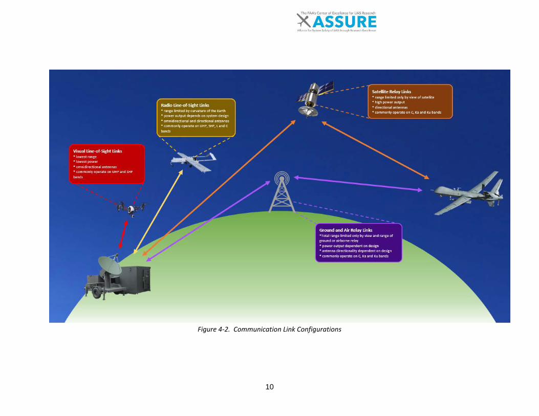
10
Figure 4-2. Communication Link Configurations
11
4.2.2 Communication Link Maintenance Tasks
A list of maintenance tasks for communication links was created to aid in identifying the required skills. Procedural and repair tasks were identified through Certificate of Authorization (COA) and Section 333 incident and accident reports provided from the FAA, the NCATT Unmanned Aircraft System Maintenance Standard, the DACUM Research Chart for UAS Maintenance Technician, the Maintenance and Repair Da-tabase, United States Air Force Accident Reports and a list of tasks for a complex CS shared by Northland Community and Technical College (NCTC) called the Modified Shelter Tech Task List [18]. The incident and accident reports were primarily utilized to discover repair tasks, while all other sources were used to un-cover both repair and procedural maintenance tasks. To view the entire task list and the sources of each specific task refer to Appendix A. Antennas were found to have several potential corrective and regular maintenance tasks. The M&R data-base indicated inspections of both antennas and their respective connectors. In addition to inspections, packing and unpacking antennas as well as setting up directional antennas were listed as preventative tasks conducted on antennas. For antennas that include an antenna tracker mount, a mount that is de-signed to move and point the antenna at a target, configuration, lubrication and inspection were defined as preventative tasks for the antenna tracker mount. The corrective tasks discovered for antennas included removal and replacement of antennas as well as mounting antennas and tuning antennas. Maintainers were also found to conduct maintenance on radio monitoring devices such as spectrum ana-lyzers. The tasks for these components included configuring and checking proper operation of radio fre-quency monitors and spectrum analyzers. Transmitters, receivers and transceivers also require maintenance tasks. Tests of transmitter output power were the only preventative task discovered. Corrective tasks outnumbered the single preventative task and include removal and replacement of faulty transmitters, receivers, transceivers and modems. There were several tasks for the communication link system as a whole. Typical tasks for the communica-tion link included: conducting pre and post operational checks for the communication link system, config-uring the link, checking the status of the link, and checking for proper operation of the link. Satellite com-munication links as seen in orange in Figure 4-2 require additional tasks such as checking operation of reach-back loops and loopbacks, which can detect problems in the link through self-testing. A few correc-tive tasks were also discovered including troubleshooting broken or degraded links and other faults in the link system. A handful of other miscellaneous tasks were also found. These tasks were corrective and involved removal and replacement of faulty components such as attenuators and amplifiers. Electrical tasks were also dis-covered that were not specific to communication link components. These included troubleshooting and replacing electrical components and wiring and inspecting wiring. These tasks may not present a complete representation of communication link maintenance but should give an indication of common skills a main-tainer needs to maintain UAS communication links.

12
4.2.3 Knowledge and Skills Required to Maintain Communication Links
To form a larger picture of the skill and knowledge required to maintain communication links, further in-formation than the list of tasks discussed in Section 1.1.1 is required. Therefore, a list of skill and knowledge was created using an industry certification for UAS maintainers, the NCATT Unmanned Aircraft System (UAS) Maintenance Standard, the DACUM Research Chart for UAS Maintenance Technician and the list of tasks found in appendix A and discussed in Section 1.1.1 . The full list of skill and knowledge can be found in Appendix B. The NCATT indicates maintainers require knowledge on radio principles and frequencies. This includes understanding of the various frequency bands and the federal regulations governing the various radio bands. Understanding of basic radio components such as oscillators, filters, amplifiers, tuning circuits, modulators and demodulators is also indicated as a requirement. Knowledge and skills related to antennas and transmission lines were required by NCATT and the list of tasks discussed in Section 1.1.1 . The NCATT requires that maintainers understand the various cables con-nectors and types that exist for communication link antennas. The NCATT also requires knowledge of in-stallation practices for antennas, antenna tuning and troubleshooting. As for the transmission lines which feed and are fed by antennas, the NCATT requires that maintainers understand the various types of trans-mission lines and how to install, maintain and fabricate them. An understanding of impedance, corrosion control, velocity factor and voltage standing wave ratio were indicated as well. Consistent with the UA and control station, it was found that skill and knowledge around electrical systems is applicable to communication link systems. The DACUM also covers electrical systems however, electrical systems for the UA and engine are specified, though many of the same concepts and tasks may apply. The NCATT requires that a UAS maintainer have a basic knowledge and understanding of the name and func-tion of electrical components including resistors, transformers, power supply circuits and more for both alternating and direct current systems. Other basic electricity knowledge such as how circuits function, calculation of electrical values from circuits, reading wiring diagrams and considerations for wiring and connectors are also required. A few miscellaneous electrical skills were also present in the NCATT including knowledge of electrical component heating and cooling and handling of electrostatic sensitive devices. Knowledge is not the only requirement defined by the NCATT for electrical systems. A maintainer is also required to be able to troubleshoot, inspect and repair circuits, electrical components and wiring as well as take measurements using equipment such as voltmeters and oscilloscopes. The skills discussed in this section give a picture of what skills are currently required to maintain commu-nication links in the UAS industry. This knowledge and skill can be passed by numerous methods of training to prepare maintainers.
13
4.2.4 Training Techniques for Communication Links
Two surveys were administered to UAS manufacturers and operators during Task 1 of the A5 project, titled “Level 1” and “Level 2,” [19]. The Level 1 survey provides data about the training formats in use for UAS systems maintenance. The training techniques queried during the Level 1 survey were:
• Classroom • Practical Lab (hands-on) • CD • On-Line (OEM hosted) • On-Line, Operator (2nd party) hosted • On-Line, 3rd party • Electronic File (PDF, Word, etc.)
One notable commonality between nearly all of the respondents is the use of traditional classroom in-struction, as well as hands-on lab instruction for their training. It is important to note that while all of the respondents use these methods, very few utilize them exclusively. About half of those surveyed provide either self-produced online training, or training via other electronic documents (.pdf, word, etc.), or both. Other training formats, such as CD-ROM, and training through 2nd and 3rd party online providers are rare. Though the Level 1 surveys focused on the unmanned aircraft portion of UAS, the training programs for these systems (whether offered in-house or by a 2nd or 3rd party) include training for the entire system; as a result, some of the respondents voluntarily included additional information about other subsystems and components of their UAS during the surveys. The Level 2 Surveys offered additional details. Very few of those surveyed presented information in terms of training for control stations; however, some of those surveyed mentioned that specific maintenance manuals exist for the non-flying UAS components. Another respondent revealed that they provide training programs for control stations, automated landing systems, landing mechanisms, and portable electrical power requirements. For this case, the training is delivered through traditional classroom instruction, hands-on labs, and offered online through a 3rd party source. Neither the A5 Task 1 survey literature nor internal training sources (NCTC and KSU) revealed any notable distinctions between training techniques offered for communication systems versus UAS CS and support equipment. Again, some respondents mentioned that specific maintenance manuals exist for communi-cation systems. One company offers dedicated training for how to obtain datalink spectrum approvals in various parts of the world. In conclusion, based on the sources of data examined, classroom instruction and hands-on lab training are the most common forms of techniques employed by a small sampling of manufacturers, operators, and training institutions. There were no indications of differing techniques between sub-systems such as Com-munication Systems, Control Stations and Support Equipment.

14
5 RECOMMENDATIONS
Based on the skills identified in Section 4.2.3 , several were chosen to represent the primary skills a main-tainer needs to maintain communication links. These skills include two delineations: (1) skills that a Part 65 certified airframe and powerplant (A&P) rated manned aviation mechanic will already have been trained per Advisory Circular 65-2D [20]; and (2) skills that are new to an A&P mechanic. Additional skills were also chosen separate from the skills list discussed in Appendix B based on knowledge about primary communication link components discussed in Section 4.2.1 and categories of maintenance tasks outlined by ATA iSpec 2200. The full list of recommended skills can be found in Table 5-1. Skills covered by AC 65-2D are denoted by a black solid bullet point while skills not found in the AC are denoted by an arrow. Skills partially covered by AC 65-2D are denoted by an open bullet point.
Table 5-1. Primary Skills
Basic Radio Principles Understand frequency bands and their common uses Understand radio terms and components including receiver sensitivity, tuning circuits, ampli-
fiers, oscillators, modulators, demodulators, and filters • Understand FAA and FCC radio regulations
Antennas, Transmission Lines and Antenna Trackers o Troubleshoot, remove, install, adjust and inspect antennas including satcom antennas Understand antenna variants Troubleshoot, service, adjust and check antenna trackers Understand antenna tracker operations • Remove, install, inspect and repair transmission lines Understand types of transmission line, velocity factor, impedance and voltage standing wave
ratio Radio Monitoring Remove, install and check spectrum analyzers Remove, install and check radio frequency monitors
Transmitting and Receiving o Remove, install, adjust and check transmitters, receivers and transceivers Configure and check satellite loopbacks and reach back loops Configure and check functionality of link integrity and self-testing functions Troubleshoot broken and degraded communication links Remove, install, adjust and check amplifiers and attenuators
Electrical Systems Troubleshoot, service, install and remove power supplies including uninterruptable power
supplies (UPS) Check, install and remove electrical outlets • Remove and install light bulbs and fixtures • Understand wiring diagrams
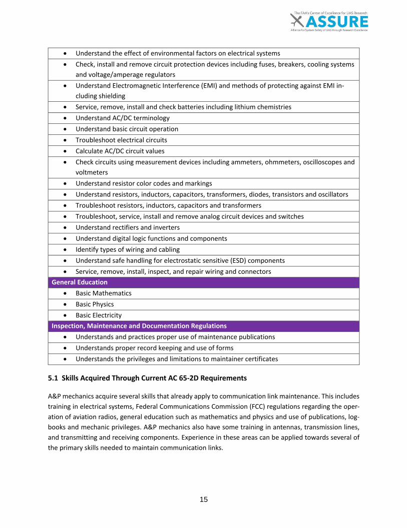
15
• Understand the effect of environmental factors on electrical systems • Check, install and remove circuit protection devices including fuses, breakers, cooling systems
and voltage/amperage regulators • Understand Electromagnetic Interference (EMI) and methods of protecting against EMI in-
cluding shielding • Service, remove, install and check batteries including lithium chemistries • Understand AC/DC terminology • Understand basic circuit operation • Troubleshoot electrical circuits • Calculate AC/DC circuit values • Check circuits using measurement devices including ammeters, ohmmeters, oscilloscopes and
voltmeters • Understand resistor color codes and markings • Understand resistors, inductors, capacitors, transformers, diodes, transistors and oscillators • Troubleshoot resistors, inductors, capacitors and transformers • Troubleshoot, service, install and remove analog circuit devices and switches • Understand rectifiers and inverters • Understand digital logic functions and components • Identify types of wiring and cabling • Understand safe handling for electrostatic sensitive (ESD) components • Service, remove, install, inspect, and repair wiring and connectors
General Education • Basic Mathematics • Basic Physics • Basic Electricity
Inspection, Maintenance and Documentation Regulations • Understands and practices proper use of maintenance publications • Understands proper record keeping and use of forms • Understands the privileges and limitations to maintainer certificates
5.1 Skills Acquired Through Current AC 65-2D Requirements
A&P mechanics acquire several skills that already apply to communication link maintenance. This includes training in electrical systems, Federal Communications Commission (FCC) regulations regarding the oper-ation of aviation radios, general education such as mathematics and physics and use of publications, log-books and mechanic privileges. A&P mechanics also have some training in antennas, transmission lines, and transmitting and receiving components. Experience in these areas can be applied towards several of the primary skills needed to maintain communication links.

16
When comparing the skills outlined in AC 65-2D to Table 5-1, it was found that an A&P should have an adequate degree of skill in electrical systems to maintain communication links. A&P mechanics are trained in most of the primary skills found under “Electrical Systems” in Table 5-1. The only electrical skill an A&P mechanic may find unfamiliar is lithium batteries and uninterruptable power supplies (UPS). Lithium bat-teries are found in many small unmanned aircraft as well as in laptops and tablets. UPS are found in some control stations as a backup source of power. Both lithium packs and UPS are included as a backup power source for surface equipment including communications equipment in the case the primary source of power fails. While their training is not specific to UAS communication links, A&P mechanics are trained to maintain manned aviation radios as well as antennas onboard aircraft. However, AC 65-2D reflects a limited scope of training in regards to antennas and transmission lines. A&P mechanics are trained how to maintain antennas and transmission lines but according to AC 65-2D are not required to learn how to name and explain the properties of various types of antennas and transmission lines. Likewise, A&P mechanics are required to be able to maintain and work on transmitting and receiving equipment including voice com-munications and navigation equipment which may be similar to some UAS communications components. Other skill areas an A&P has that applies to maintenance of communication links includes knowledge of the records, forms and logbooks required to be kept for certified aircraft and education in basic physics, electricity and mathematics. An A&P has a starting set of skills that can help them maintain communication links however, additional skill is required to familiarize the mechanic with the components and systems they will encounter.
5.2 Skills Not Found in AC 65-2D
An A&P mechanic has most of the primary skills listed in Table 5-1 according to the requirements in AC 65-2D. Gaps do exist however in skill areas such as radio monitoring equipment, some transmitting and re-ceiving components, antenna trackers and some basic radio principles. While AC 65-2D requires knowledge of FCC and FAA regulations regarding radio operations, principles such as understanding radio terms, frequency bands and bands allocation is not explicitly required. This would mean that an A&P mechanic would require additional training to understand these concepts. Having this knowledge would benefit a maintainer by allowing them to understand the components in the system and potential problems that may arise when using certain frequency bands. Furthermore, an A&P mechanic would need expanded training regarding antennas and transmission lines along with training in skills related to antenna trackers. An understanding of the various types of antennas and transmission lines and their uses would help a maintainer identify appropriate replacement parts and locate issues related to the characteristics of certain types of antennas. With directional antennas in par-ticular one additional consideration is antenna trackers. Being able to maintain antenna trackers would help the maintainer ensure highly directional antennas are always pointed at their target receiving the best signal.

17
Even if the antenna and antenna tracker is working as designed the maintainer would still need to ensure the transmitting and receiving components of a communication link are properly cared for. An A&P would be able to maintain radio transmitters and receivers but would be unfamiliar to UAS communication link systems. Therefore, additional training would be required to acquire the skills needed to troubleshoot UAS communications links, configure and check link self-testing features, configure and check satellite loop-backs and reach back loops and to maintain amplifiers and attenuators. These aspects of communication link maintenance help ensure communication links have integrity and are working properly.
5.3 Conclusions
UAS communication links present several unique maintenance elements despite having several similarities to manned aviation radios. Unlike manned aviation, the maintainer of a UAS must maintain both the send-ing and receiving ends of a radio transmission. These systems, though physically separate, are still parts of the same communication link system and must be maintained as a system to ensure safe and successful operations. Maintenance of the communication link system requires collaboration between the surface elements and the UA. In addition, differing environmental conditions on the surface and air components may cause more or less wear on that element of the system. An A&P mechanic will be familiar with many aspects of a communication link system but still requires additional training to perform the specific skills unique to maintaining communication links. An A&P me-chanic’s training in voice communication and navigation radio with a background in electrical systems pro-vides a mechanic with most of the skills required to maintain communication links. Training would still be required to learn skills to troubleshoot and test UAS communication links, maintain satellite links and an-tenna tracking mounts. Additional training in these areas for an A&P mechanic would help achieve the final goal of a certified maintainer that is prepared to work with unmanned aircraft systems.

18
6 REFERENCES
[1] ASTM F2909-14, Standard Practice for Maintenance and Continued Airworthiness of Small Un-
manned Aircraft Systems (sUAS), ASTM International, 2014.
[2] ASTM F3002-14a Standard Specification for Design of the Command and Control System for Small
Unmanned Aircraft Systems (sUAS). doi: 10.1520, ASTM International, 2014.
[3] "Association for Unmanned Vehicle Systems International – UAS Platform Database," 2016.
[4] D. M. Marshall, R. K. Barnhart, E. Shappee and M. Most, Introduction to Unmanned Aircraft Systems
(2nd edition), Boca Raton: Taylor & Francis, CRC Press, 2016.
[5] A. Hobbs and S. R. Herwitz, Human Challenges in the Maintenance of Unmanned Aircraft Systems,
FAA and NASA Report, 2006.
[6] A. Hobbs and R. J. Shively, Human Factor Challenges of Remotely Piloted Aircraft Available at
http://human-factors. arc. nasa. gov/publications/Hobbs_EAAP. pdf., NASA, 2014.
[7] A. Hobbs and Herwitz, Human Factors in the Maintenance of Unmanned Aircraft. Small, 15(100),
2014.
[8] A. Hobbs and Herwitz, Maintenance Challenges of Small Unmanned Aircraft Systems - A Human
Factors Perspective. doi:10.13140/RG.2.1.1858.8647, 2008.
[9] "U.S. Air Force Fact Sheets @ http://www.af.mil/AboutUs/FactSheets.aspx," [Online].
[10] "U.S. Army Unmanned Aircraft Systems Repairer (15E) (n.b.) career profile," [Online]. Available:
http://www.goarmy.com/careers-and-jobs/browse-career-and-job-categories/transportation-and-
aviation/unmanned-aircraft-systems-repairer.html. [Accessed 04 April 2017].
[11] "U.S. Army Unmanned Aircraft Systems Operator (15W) (n.d.) career profile," [Online]. Available:
http://www.goarmy.com/careers-and-jobs/browse-career-and-job-categories/transportation-and-
aviation/unmanned-aerial-vehicle-operator.html. [Accessed 04 April 2017].
[12] "U.S. Air Force Remotely Piloted Aircraft Maintenance career profile @
https://www.airforce.com/careers/detail/remotely-piloted-aircraft-maintenance," [Online].
[13] "U.S. Marines MOS 6314 Avionics/Maintenance Technician, Unmanned Aircraft System (UAS) career
profile," [Online]. Available: http://www.cool.navy.mil/usmc/enlisted/6314.htm. [Accessed 04 April
2017].

19
[14] M. Mouloua, R. Gilson, E. Daskarolis-Kring, J. Kring and P. Hancock, "Ergonomics of UAV/UCAV
mission success: Considerations for data link, control, and display issues (2001, October)," in
Proceedings of the Human Factors and Ergonomics Society Annual Meeting, Los Angeles, CA, 2001.
[15] R. Sollenberger, D. M. McAnulty and K. Kerns, "The effect of voice communications latency in high
density, communications-intensive airspace. (Report No. DOT/FAA/CT-TN03/04)," Federal Aviation
Authority., Washington DC:, 2003.
[16] "RQ-4 Global Hawk. (2014, October 27).," [Online]. Available:
http://www.af.mil/AboutUs/FactSheets/Display/tabid/224/Article/104516/rq-4-global-hawk.aspx.
[Accessed 27 February 2017].
[17] U. T. Force, The Joint JAA/EUROCONTROL Initiative on UAVs. UAV Task Force Final Report., 2004.
[18] N. A. Northland Community and Technical College, Modified Shelter Task List., 2017.
[19] K. Barnhart, S. Ley, T. Bruner, M. Most and A. Meyer, "Draft Technical Report of UAS Maintenance
Data Preliminary Analysis," Kansas State University, Manhattan, 2016.
[20] Airframe and Powerplant Mechanics Certification Guide, Advisory Circular 65-2D, 1976.
[21] Airmen other than Flight Crew Members, 14 C.F.R. pt. 65, 2011.
[22] "General Radiotelephone Operator License (PG). (n.d.)," 13 March 2017. [Online]. Available:
http://wireless.fcc.gov/commoperators/index.htm?job=pg.
[23] Unmanned Aircraft System (UAS) Maintenance Standard, National Center for Aerospace and
Transportation Technologies, 2012.
[24] "333COA GCS and Comm Incident Acccident Database," Kansas State University, Applied Aviation
Research Center, 2017.
[25] "Maintenance and Repair Database.," Kansas State University, Applied Aviation Research Center,
2016.
[26] Aviation Maintenance Technician Schools, 14 C.F.R. pt. 147, 2011.
[27] Aircraft Electronics Technician (AET) Standard, National Center for Aerospace and Transportation
Technologies, 2009.

20
APPENDIX A: COMMUNICATION LINK TASK LIST
This list is all maintenance tasks for communication links found in the NCATT UAS, COA and 333 accident reports, the Modified Shelter Task List and the USAF accident reports.
System Sub-System Task Type Task Description Source Comm Amplifier Corrective Remove/replace radio amplifier Modified Shelter
Tech Task List Comm Antenna Corrective Replace antennas COA/333 Reports Comm Antenna Corrective Tune/troubleshoot antennas NCATT Comm Antenna Corrective Install and mount antennas NCATT Comm Antenna Corrective Remove/replace satellite communi-
cation antenna Modified Shelter Tech Task List
Comm Antenna Preventa-tive
Inspect antenna connectors M&R
Comm Antenna Preventa-tive
Inspect antennas M&R
Comm Antenna Preventa-tive
Setup directional antennas Modified Shelter Tech Task List
Comm Antenna Preventa-tive
Prepare antenna equipment for shipping
Modified Shelter Tech Task List
Comm Antenna Tracker
Preventa-tive
Configure antenna tracker control unit
Modified Shelter Tech Task List
Comm Antenna Tracking
Corrective Realign satellite antenna trackers COA/333 Reports
Comm Antenna Tracking
Preventa-tive
Lubricate antenna tracker assembly Modified Shelter Tech Task List
Comm Antenna Tracking
Preventa-tive
Inspect antenna tracker Modified Shelter Tech Task List
Comm Attenuators Corrective Remove/replace ground RF attenu-ator
Modified Shelter Tech Task List
Comm Link - Gen-eral
Corrective Troubleshoot broken or degraded links
COA/333 Reports
Comm Link - Gen-eral
Corrective Troubleshoot communication links NCATT
Comm Link - Gen-eral
Corrective Remove/replace data interface as-sembly
Modified Shelter Tech Task List
Comm Link - Gen-eral
Preventa-tive
Data link Power up/down Modified Shelter Tech Task List
Comm Link - Gen-eral
Preventa-tive
Data link configuration Modified Shelter Tech Task List
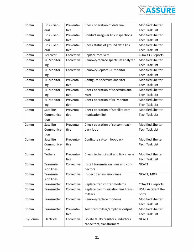
21
Comm Link - Gen-eral
Preventa-tive
Check operation of data link Modified Shelter Tech Task List
Comm Link - Gen-eral
Preventa-tive
Conduct irregular link inspections Modified Shelter Tech Task List
Comm Link - Gen-eral
Preventa-tive
Check status of ground data link Modified Shelter Tech Task List
Comm Receiver Corrective Replace receivers COA/333 Reports Comm RF Monitor-
ing Corrective Remove/replace spectrum analyzer Modified Shelter
Tech Task List Comm RF Monitor-
ing Corrective Remove/Replace RF monitor Modified Shelter
Tech Task List Comm RF Monitor-
ing Preventa-tive
Configure spectrum analyzer Modified Shelter Tech Task List
Comm RF Monitor-ing
Preventa-tive
Check operation of spectrum ana-lyzer
Modified Shelter Tech Task List
Comm RF Monitor-ing
Preventa-tive
Check operation of RF Monitor Modified Shelter Tech Task List
Comm Satellite Communica-tion
Preventa-tive
Check operation of satellite com-munication link
Modified Shelter Tech Task List
Comm Satellite Communica-tion
Preventa-tive
Check operation of satcom reach-back loop
Modified Shelter Tech Task List
Comm Satellite Communica-tion
Preventa-tive
Configure satcom loopback Modified Shelter Tech Task List
Comm Tethers Preventa-tive
Check tether circuit and link checks Modified Shelter Tech Task List
Comm Transmis-sion lines
Corrective Install transmission lines and con-nectors
NCATT
Comm Transmis-sion lines
Corrective Inspect transmission lines NCATT, M&R
Comm Transmitter Corrective Replace transmitter modems COA/333 Reports Comm Transmitter Corrective Replace communication link trans-
mitters USAF Accident Re-ports
Comm Transmitter Corrective Remove/replace modems Modified Shelter Tech Task List
Comm Transmitter Preventa-tive
Test transmitter/amplifier output Modified Shelter Tech Task List
CS/Comm Electrical Corrective Isolate faulty resistors, inductors, capacitors, transformers
NCATT
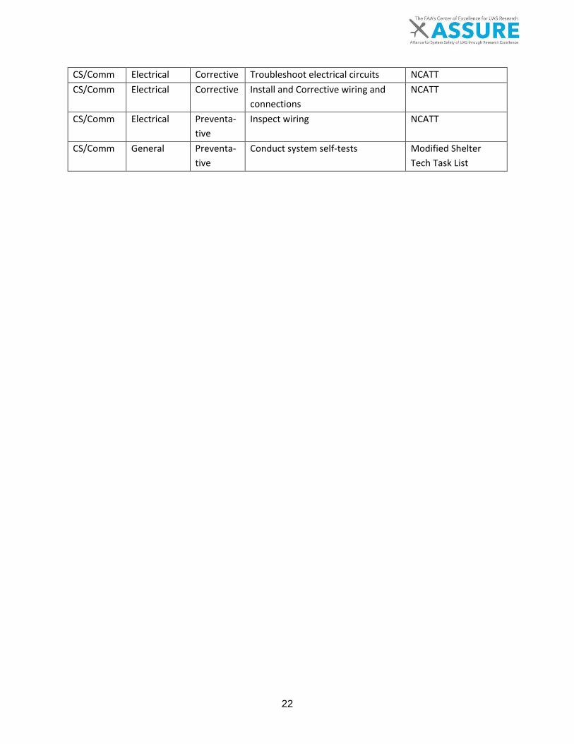
22
CS/Comm Electrical Corrective Troubleshoot electrical circuits NCATT CS/Comm Electrical Corrective Install and Corrective wiring and
connections NCATT
CS/Comm Electrical Preventa-tive
Inspect wiring NCATT
CS/Comm General Preventa-tive
Conduct system self-tests Modified Shelter Tech Task List
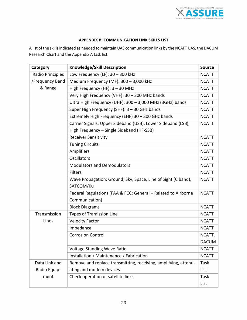
23
APPENDIX B: COMMUNICATION LINK SKILLS LIST
A list of the skills indicated as needed to maintain UAS communication links by the NCATT UAS, the DACUM Research Chart and the Appendix A task list.
Category Knowledge/Skill Description Source Radio Principles
/Frequency Band & Range
Low Frequency (LF): 30 – 300 kHz NCATT Medium Frequency (MF): 300 – 3,000 kHz NCATT High Frequency (HF): 3 – 30 MHz NCATT Very High Frequency (VHF): 30 – 300 MHz bands NCATT Ultra High Frequency (UHF): 300 – 3,000 MHz (3GHz) bands NCATT Super High Frequency (SHF): 3 – 30 GHz bands NCATT Extremely High Frequency (EHF) 30 – 300 GHz bands NCATT Carrier Signals: Upper Sideband (USB), Lower Sideband (LSB), High Frequency – Single Sideband (HF-SSB)
NCATT
Receiver Sensitivity NCATT Tuning Circuits NCATT Amplifiers NCATT Oscillators NCATT Modulators and Demodulators NCATT Filters NCATT Wave Propagation: Ground, Sky, Space, Line of Sight (C band), SATCOM/Ku
NCATT
Federal Regulations (FAA & FCC: General – Related to Airborne Communication)
NCATT
Block Diagrams NCATT Transmission
Lines Types of Tramission Line NCATT Velocity Factor NCATT Impedance NCATT Corrosion Control NCATT,
DACUM Voltage Standing Wave Ratio NCATT Installation / Maintenance / Fabrication NCATT
Data Link and Radio Equip-
ment
Remove and replace transmitting, receiving, amplifying, attenu-ating and modem devices
Task List
Check operation of satellite links Task List

24
Check and inspect data links Task List
Check spektrum analyzers and other RF monitors Task List
Remove and replace spektrum analyzers and other RF monitors Task List
Troubleshoot communication/data links Task List
Configure and check satellite loopback Task List
Antennas Aircraft installation NCATT Antenna Types NCATT Grounding and Bonding NCATT Tuning / Troubleshooting NCATT Antenna Cabling NCATT Antenna Connectors NCATT Antenna Couplers NCATT Antenna Installation and mounting Task
List Antenna tracker alignment and configuration Task
List Antenna tracker lubrication Task
List Removal and replace - Antennas Task
List Removal and replace - Satellite Antennas Task
List Hardware NCATT
Electrostatic Sensitive Device (ESD): Electro-
static-Discharge-Sensitive Equip-
ment and/or Parts
Identification, markings and warning labels NCATT Handling ESDs and ESD handling equipment NCATT ESD Transportation NCATT
General Electri-cal Systems
Wiring Considerations: heat, wear and connectors NCATT Wiring Diagrams NCATT
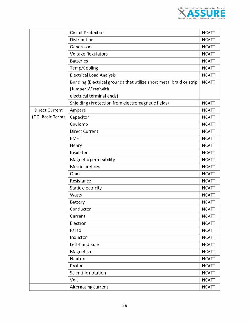
25
Circuit Protection NCATT Distribution NCATT Generators NCATT Voltage Regulators NCATT Batteries NCATT Temp/Cooling NCATT Electrical Load Analysis NCATT Bonding (Electrical grounds that utilize short metal braid or strip [Jumper Wires]with electrical terminal ends)
NCATT
Shielding (Protection from electromagnetic fields) NCATT Direct Current
(DC) Basic Terms Ampere NCATT Capacitor NCATT Coulomb NCATT Direct Current NCATT EMF NCATT Henry NCATT Insulator NCATT Magnetic permeability NCATT Metric prefixes NCATT Ohm NCATT Resistance NCATT Static electricity NCATT Watts NCATT Battery NCATT Conductor NCATT Current NCATT Electron NCATT Farad NCATT Inductor NCATT Left-hand Rule NCATT Magnetism NCATT Neutron NCATT Proton NCATT Scientific notation NCATT Volt NCATT Alternating current NCATT

26
Alternating Cur-rent (AC) Basic
Terms
Apparent power NCATT Capacitive reactance NCATT Delta wound NCATT Effective NCATT Frequency NCATT Impedance NCATT Inductive reactance NCATT Phase NCATT Polyphase NCATT Power factor NCATT Rectifier NCATT Resistance NCATT Root Mean Square (RMS) NCATT Sine wave NCATT True power NCATT Wye wound NCATT
Basic Circuit Theory of Opera-
tion
Amps NCATT Bridge circuits NCATT Complex circuits NCATT Joules NCATT Kirchhoff’s Law NCATT Ohm’s Law NCATT Parallel circuits NCATT Power NCATT Resistance NCATT Resistors in parallel circuits NCATT Resistors in series circuits NCATT Series circuits NCATT Voltage drop NCATT Volts NCATT Watts NCATT
Basic Circuit Troubleshooting
Troubleshooting Theory NCATT Bridge circuits NCATT Complex circuit voltage drop NCATT Kirchhoff’s Law NCATT Parallel circuit NCATT Resistors in parallel circuit NCATT

27
Resistors in series circuit NCATT Series circuit NCATT
AC Circuit Calcu-lations
Apparent power NCATT Capacitance NCATT Capacitive reactance NCATT Effective voltage NCATT Frequency NCATT Impedance NCATT Inductance NCATT Inductive reactance NCATT Peak Voltage NCATT Period NCATT Phase angle NCATT Power Factor NCATT Resonance NCATT True power NCATT
DC Circuit Calcu-lations
Amps NCATT Ohms NCATT Volts NCATT Watts NCATT
DC / AC Basic Circuit Measure-
ments
Ammeters NCATT Ohmmeters NCATT Oscilloscopes NCATT Voltmeters NCATT
Resistor / Color Codes
Use of color codes to identify resistor / resistance values NCATT Calculate resistance values based on color codes NCATT
Resistor / Fault Isolation
Improperly installed Resistors NCATT Open Resistors NCATT Resistors of incorrect value NCATT Shorted Resistors NCATT
Inductors Theory of Operation NCATT Isolate Faulty Inductors NCATT
Capacitor / The-ory of Operation
Calculation of capacitive reactance NCATT Correct operation of Capacitors NCATT Dielectric NCATT Electrolytic NCATT Farad NCATT

28
Fixed Capacitors NCATT Time constants NCATT Use of multiple Capacitors NCATT Variable Capacitors NCATT
Capacitor / Fault Isolation
Improperly installed Capacitors NCATT Open Capacitors NCATT Shorted Capacitors NCATT
Transformer / Theory of Opera-
tion
Counter Electro Magnetic Field (EMF) NCATT Eddy currents NCATT Hysteresis NCATT Primary winding NCATT Secondary winding NCATT Step-down NCATT Step-up NCATT
Transformer / Fault Isolation
Improperly installed Transformers NCATT Open or shorted Primary Coil NCATT Primary and secondary resistance testing NCATT Secondary Coil NCATT
Analog Circuits, Devices & Switches
Derating factors NCATT Double Pull Double Throw (DPDT) NCATT Double Pull Single Throw (DPST) NCATT Micro Switch NCATT Normally closed NCATT Normally open NCATT Proximity switches NCATT Push button Switch NCATT Relays NCATT Rocker NCATT Rotary NCATT Solenoids NCATT SPDT NCATT Switches NCATT Toggle NCATT
Power Supply Circuit / Rectifi-
ers
Diode NCATT Forward bias NCATT Full-wave Rectifier NCATT Germanium NCATT

29
Half-wave Rectifier NCATT Reverse bias NCATT Ripple amplitude NCATT Silicon NCATT Solid-state NCATT Three phase Rectifier NCATT Types of components used NCATT Use of power supply circuits NCATT
Power Supply Circuit / Filters
Active filters NCATT Passive filters NCATT
Frequency Sensi-tive Filter - The-ory of Operation
Band-pass NCATT Band-reject NCATT Cutoff frequency NCATT Demodulation NCATT Detection NCATT Filtering NCATT High-pass NCATT Tuning circuit NCATT Use of crystals NCATT
Wave Genera-tion Circuits
Oscillators NCATT Waveshaping Circuits NCATT
Limiter Circuits Diodes NCATT Zener Diodes NCATT Transistors NCATT
Digital Number-ing Systems
Binary NCATT Octal NCATT Hexadecimal NCATT
Digital Logic Functions
Main Logic Gates NCATT Flip-Flops NCATT Counters NCATT Adders NCATT
Types of Aircraft Wiring / Cabling
Coaxial Cable NCATT Databus (Multiplex) Cables NCATT Multiconductor NCATT Twisted Pair NCATT Fiber Optics NCATT Lacing / Tying Wire Bundles NCATT
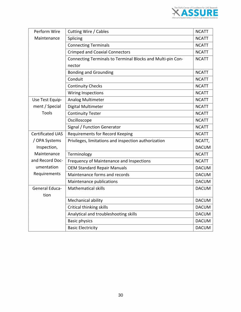
30
Perform Wire Maintenance
Cutting Wire / Cables NCATT Splicing NCATT Connecting Terminals NCATT Crimped and Coaxial Connectors NCATT Connecting Terminals to Terminal Blocks and Multi-pin Con-nector
NCATT
Bonding and Grounding NCATT Conduit NCATT Continuity Checks NCATT Wiring Inspections NCATT
Use Test Equip-ment / Special
Tools
Analog Multimeter NCATT Digital Multimeter NCATT Continuity Tester NCATT Oscilloscope NCATT Signal / Function Generator NCATT
Certificated UAS / OPA Systems
Inspection, Maintenance
and Record Doc-umentation
Requirements
Requirements for Record Keeping NCATT Privileges, limitations and inspection authorization NCATT,
DACUM Terminology NCATT Frequency of Maintenance and Inspections NCATT OEM Standard Repair Manuals DACUM Maintenance forms and records DACUM Maintenance publications DACUM
General Educa-tion
Mathematical skills DACUM
Mechanical ability DACUM Critical thinking skills DACUM Analytical and troubleshooting skills DACUM Basic physics DACUM Basic Electricity DACUM
A.5 UAS Maintenance, Modification, Repair, Inspection, Training, and Certification Considerations
TASK 4C: DEVELOP MAINTENANCE TECHNICIAN TRAINING REQUIREMENTS
In-Depth Analysis of Areas that Require Special Considerations
I. Non-Metallic material structures II. Ground control stations and support equipment
III. Communication links IV. Software and autopilots

ii
NOTICE
This document is disseminated under the sponsorship of the U.S. Department of Transportation in the interest of information exchange. The U.S. Government assumes no liability for the contents or use thereof. The U.S. Government does not endorse products or manufacturers. Trade or manufacturers’ names appear herein solely because they are considered essential to the objective of this report. The findings and conclusions in this report are those of the author(s) and do not necessarily represent the views of the funding agency. This document does not constitute FAA policy. Consult the FAA sponsoring organization listed on the Technical Documentation page as to its use.

iii
Legal Disclaimer: The FAA has sponsored this project through the Center of Excellence for Unmanned Aircraft Systems. However, the agency neither endorses nor rejects the findings of this research. The presentation of this information is in the interest of invoking technical com-ment on the results and conclusions of the research.
iv
Technical Report Documentation Page Title: .5 UAS Maintenance, Modification, Repair, Inspection, Training, and Certification Consid-erations: In-depth Analysis of Software and Autopilots Report Date: 6 November 2017 Performing Organizations: Embry-Riddle Aeronautical University Authors: John M. Robbins, Ph.D., Mitch Geraci, M.S., Richard Stansbury, Ph.D., Charles Nick
Performing Organization Address: Embry-Riddle Aeronautical University 600 S. Clyde Morris Blvd Daytona Beach, FL 32114
Sponsoring Agency Name and Address: U.S. Department of Transportation Federal Aviation Administration Washington, DC 20591

v
Table of Contents Page
1 EXECUTIVE SUMMARY 1
2 SCOPE 2
3 INTRODUCTION 3
4 LITERATURE REVIEW 4
4.1 AUTOPILOT SYSTEMS 4
4.2 INTEROPERABILITY 5
4.3 CERTIFICATION AND CONTINUED AIRWORTHINESS STANDARDS 5
4.4 UAS SOFTWARE APPLICATIONS 6
5 RECOMMENDATIONS 7
5.1 AUTOPILOT MAINTENANCE AND REPAIR 7
5.2 SOFTWARE MAINTENANCE AND REPAIR 8
5.3 ADDITIONAL MAINTAINER REQUIREMENTS FOR UAS TECHNOLOGIES 9
6 CONCLUSIONS 11
7 DEFINITIONS 12
8 ACRONYMS 17
9 REFERENCES 19

vi
LIST OF TABLES
TABLE 2-1. A5 Task 4 Work Breakdown Structure…………………………………………….2

1 Executive Summary
Research conducted during Task 4civ provides an in-depth analysis that details current mainte-nance protocols and procedures for autopilot and software items related to Unmanned Aircraft systems (UAS). The outcome of this task will further define how existing protocols may be mod-ified to better understand and recommend skills required to maintain these two important items. Operator and maintainers require skills necessary to provide support to UAS equipment related to autopilot systems and software components, both in the field and at their respective workplace. The use of Software and Autopilots are an integral component of UAS technologies. The integra-tion of these systems requires, in many cases, a developed understanding of computer program-ming and a well-defined background in computing applications and usability. The systems de-scribed in this report are representative of those currently in the field and provide a multitude of operational capabilities with varying levels of user skill required. Further understanding of elements specific to UAS technologies will aid in the development of regulation and training standards. Recommendations in this study define additional training and skill requirements UAS technicians must possess in order to safely maintain and repair UAS soft-ware and autopilot equipment.
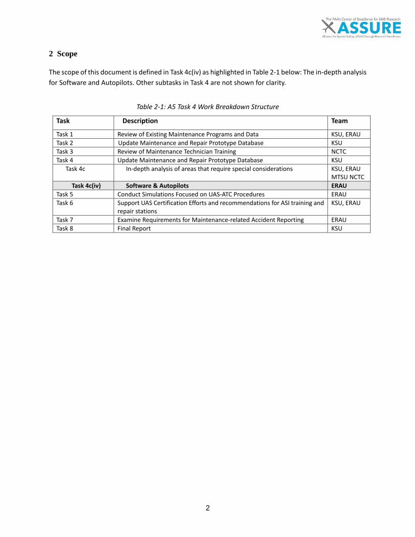
2
2 Scope
The scope of this document is defined in Task 4c(iv) as highlighted in Table 2-1 below: The in-depth analysis for Software and Autopilots. Other subtasks in Task 4 are not shown for clarity.
Table 2-1: A5 Task 4 Work Breakdown Structure
Task Description Team
Task 1 Review of Existing Maintenance Programs and Data KSU, ERAU Task 2 Update Maintenance and Repair Prototype Database KSU Task 3 Review of Maintenance Technician Training NCTC Task 4 Update Maintenance and Repair Prototype Database KSU
Task 4c In-depth analysis of areas that require special considerations KSU, ERAU MTSU NCTC
Task 4c(iv) Software & Autopilots ERAU Task 5 Conduct Simulations Focused on UAS-ATC Procedures ERAU Task 6 Support UAS Certification Efforts and recommendations for ASI training and
repair stations KSU, ERAU
Task 7 Examine Requirements for Maintenance-related Accident Reporting ERAU Task 8 Final Report KSU

3
3 Introduction
The analysis of UAS autopilot and software technologies, including current UAS maintainer cer-tification standards, is necessary in order to understand how field operations and current train-ing/certification standards may need to be modified to accommodate industry needs. Variability in platform design and availability have created a market for command and control (C2) technol-ogies to include software and autopilot systems that range from high levels of interaction to limited or no interaction from the user. The variety of designs of accessible versus secure software and autopilot systems must be examined in order to understand the requirements users must meet for each system. The complexity of systems may range, however, it is important to understand the role of the operator and maintainer in order to assure they are compliant with future operational considerations, guidelines, and standards. Software and autopilot systems range in complexity, capability, and price. Some small Unmanned Aircraft Systems (sUAS) manufacturers protect the software from modification by the user through the use of proprietary (closed architecture) software and hardware components. Other manufacturers allow the operator/user to modify elements and integral functions of the software through the use of popular programming languages (open-architecture). The level of interaction by the user is a function of experience and mission needs. For instance, a sUAS operator who is entering industry as a real-estate photographer may have little need to modify onboard software to accomplish a given mission. The operator of an aircraft used to conduct data collection used in photogrammetry may need to modify software or autopilot configurations to better fit the needs of the mission. UAS larger than those classified as sUAS often incorporate complex autopilot sys-tems that allow the user more control authority. Piccolo Cloud Cap Technology, used in a host of high endurance platforms, allow the user to mod-ify or change software and autopilot configurations to enhance mission capability through the use of proprietary software. The Pixhawk autopilot system allows the user a high level of interaction to modify coding through a true open-architecture system. Complex systems such as the Predator and Global Hawk airframes hold protected or classified software and autopilot data. The level of complexity associated with UAS systems is highly variable. Some platforms have a defined or narrowed mission set, while others have a multitude of capabilities. Consumer grade systems such as the DJI phantom have software and autopilot hardware installed by the manufac-turer that limits the user by only allowing configuration changes through the use of application or website based exchanges. Any modification to this software is protected by the manufacturer and user capabilities are limited based on mission capabilities. High endurance platforms such as the Aerosonde developed by Textron Systems are capable of beyond-line-of-sight (BLOS) operations and vary in mission capability. It is important for the operator of more complex aircraft to have a higher focus of control over the software and autopilot elements in order to gain the most out of a given mission. The research conducted as part of this task helps define the role software and autopilots play in a broad platform base. The complexity and user capability to perform any type of maintenance or software associated procedure must to be outlined in order to develop maintenance standards and procedures that best represent a given class of systems.

4
4 Literature Review
A review of relevant literature was conducted to explore software and autopilot applications cur-rently in use for the operation of UAS. Software and autopilot technical data was retrieved through manufacturer websites and the review of any manuals available to the researchers. Fifteen popular autopilot systems were reviewed along with common software applications used in the civilian sector. A high level of variability exists; however, the commonalities across systems will help define user and/or maintainer requirements. Common elements exist in function, capability, pro-gramming techniques, and user interaction. However, differences can be seen across systems based on mission scope/requirements, complexity, and user experience. The results of this study may further streamline operational and maintenance considerations that allow users to better define scheduled and routine maintenance protocols. The use of data collected throughout this research could further suggest recommendations that apply to the certification of aircraft components; in particular autopilot and software systems. 4.1 AUTOPILOT SYSTEMS
Autopilot systems used in manned aircraft serve many of the same functions as those used in UAS, however, system complexity and functionality are substantially different. The primary function-ality of an autopilot is to translate command and control inputs from the Ground Control Station (GCS) to the air vehicle. This exchange of data is accomplished through a series of manual or programmed inputs delivered by an integrated software application. This interaction between sys-tems elements allows the ground based hardware to communicate with and control the air vehicle by actuating control surfaces necessary for aircraft maneuverability. Data management and acqui-sition/dissemination between UAS applications may require the autopilot system to both acquire and disseminate data from/to multiple software elements external to the aircraft. Manned aircraft require input from single or multiple hardware inputs from on-board equipment such as Global Positioning Systems (GPS), Air Data Systems (ADS), and/or Inertial Navigation Systems (INS). Autopilot systems for UAS applications are broad in capability but are specific in intent. Most autopilot hardware incorporates operational commonality regardless of open or closed systems architecture, however, programming or troubleshooting requirements vary significantly. Open Systems Architecture (OSA) implies that the system and most of its sub-systems are designed to accept the addition of new elements without redesign of the existing elements (Austin, 2010, p. 185). For instance, the open-architecture system integrated into the Pixhawk autopilot allows the user to interact through the use of simple computer programming techniques. In contrast, the NAZA system used by DJI does not allow the user to interface by manipulating the source code. Other systems, such as Piccolo, used commonly in close-range or tactical platforms, are more secure and further protected through export control policies. This high level of variability may either be restrictive or non-restrictive with regard to user interaction, which further defines the scale of user or maintainer capabilities required to support a given system. Appendix A lists a number of autopilot systems along with system parameters and expected user capabilities. The National Center For Aerospace & Transportation Technologies (NCATT) organization recom-mends a list of autopilot functions and modes technicians should be familiar which are outlined in Appendix B.

5
4.2 INTEROPERABILITY
The term interoperability refers to the similarity between systems in operation and design. The notion of interoperability has been heavily used in the UAS industry, especially in the design of GCS equipment, based on establishing common protocols for the operation of a given system. For military applications, the requirement to maintain interoperability is especially important in order to remain consistent with training and certification standards necessary to work across multiple systems. Military (MIL) or Standard North Atlantic Treaty Organization Agreement (STANAG) standards have been developed in line with the International Organisation for Standardization (ISO). STANAG 4586 defines a North American Treaty Organization (NATO) protocol and has been adopted as the Interface Control Definition (ISD) for both military and future civilian systems (Austin, 2010, p. 185). The term interoperability relates to maintenance procedures, because it creates a base for system commonality and technician skill. Similarity between systems and com-mon elements, such as interfaces, displays, hardware, components, etc. allow maintainer training and knowledge to laterally transfer across systems. 4.3 CERTIFICATION AND CONTINUED AIRWORTHINESS STANDARDS
As with other areas of UAS development, design standards at the component level are sparse. The American Society for Testing and Materials International (ASTM) has recommended seven areas of exploration for UAS technologies. The following ASTM standards define facets of small un-manned aircraft systems operations, including design, construction, operation and maintenance requirements:
• F2908 – Specification for Aircraft Flight Manual (AFM) for a Small Unmanned Aircraft System. F2908 defines minimum requirements for the aircraft flight manual, which pro-vides guidance to owners, mechanics, pilots, crew members, airports, regulatory officials and aircraft and component manufacturers who perform or provide oversight of sUAS flight operations.
• F2909 - Practice for Maintenance and Continued Airworthiness of Small Unmanned Air-craft Systems (sUAS). F2909 establishes a practice for the maintenance and continued airworthiness of sUAS. Requirements for continued airworthiness, inspections, mainte-nance and repairs/alterations are included.
• F2910 - Specification for Design and Construction of a Small Unmanned Aircraft System
(sUAS). F2910 defines the design, construction and test requirements for sUAS. In addi-tion to general requirements, F2910 covers requirements for structure, propulsion, propel-lers, fuel and oil systems, cooling, documentation and other key areas.
• F2911 - Practice for Production Acceptance of Small Unmanned Aircraft System (sUAS).
F2911 defines production acceptance requirements for sUAS. Requirements covered in-clude several aspects of production, system level production acceptance, quality assurance and documentation.

6
• F3002 - Specification for Design of the Command and Control System for Small Un-
manned Aircraft Systems (sUAS). F3002 provides a consensus standard in support of an application to a nation’s governing aviation authority to operate a sUAS for commercial or public use. The standard focuses on command and control (C2) links, including a diagram of a C2 system and general requirements for C2 system components.
• F3003 - Specification for Quality Assurance of a Small Unmanned Aircraft System
(sUAS). F3003 defines quality assurance requirements for design, manufacture and pro-duction of small unmanned aircraft systems. Guidance is given to sUAS manufacturers for the development of a quality assurance program.
• F3005 - Specification for Batteries for Use in Small Unmanned Aircraft Systems (sUAS).
F3005 defines requirements for battery cells used in sUAS. Mechanical design and safety, and electrical design battery maintenance are primary battery-related areas that are cov-ered. (ASTM, 2014)
4.4 UAS SOFTWARE APPLICATIONS
The use of software elements that combine with autopilot systems are integral to the operation of UAS technologies. Industry growth and the popularity of UAS platforms has allowed software developers the opportunity to create applications with variable levels of user interaction or capa-bilities. It is important to consider the functionality associated with different types of interfaces in order to properly assess preventative or prescribed updates for each type of application. Analytics of popular systems are described further in Appendix C, which describes the taxonomy of software through application based and proprietary or secure systems. Software systems are likely to evolve when certification and airworthiness guidance becomes available. Manned aircraft systems require software developers to manufacture avionics software in accordance with DO-178C; Software Considerations in Airborne Systems and Equipment Cer-tification. This document was set in place to minimize the risk associated with safety critical software applications.

7
5 RECOMMENDATIONS
5.1 AUTOPILOT MAINTENANCE AND REPAIR
The complexity and number of autopilot systems commercially available can make them difficult to safely and effectively troubleshoot. A primary consideration is understanding how each com-ponent functions in order to assess a given problem. The typical autopilot system is made up of gyroscopic instruments oriented in three planes, software to control the functions of the system, and hardware such as actuators and servos to move control surfaces. Onboard diagnosis of the autopilot system can often be performed during operational checks of the aircraft prior to flight. If a failure of the system has occurred, the pilot may or may not be able to fly the aircraft if the autopilot system is required. The diagnosis of an autopilot related issue in manned aircraft can be examined in a number of ways. The functionality of the system can be tested while the aircraft is in-flight by manually controlling the aircraft to a designated altitude, then engaging the autopilot system to determine where the failure or problem is most likely occurring. The issue with this method is defined by the elements of risk and safety. If the severity of the occurrence is high, the pilot of the aircraft may not feel comfortable or safe while trying to re-create the problem in the flight environment. The second and safest option is to interview the pilot to determine where and how the malfunction occurred. By referencing the pilot’s narrative, the technician may be able to test or examine equipment to find causation. Operational considerations for UAS yield the same possible solutions to determining the root cause of an autopilot related issues, but many potential problems can be found through proper pre-flight inspections. Examples of in-flight autopilot malfunctions in UAS include examples such as loss of control of the aircraft, unreliable telemetry data to the user, and the inability to manually operate the aircraft by remote control links. The benefit of performing functionality checks in UAS is often defined by autonomy and accessibility of hardware/software. The combination of software tools onboard most systems carry the functionality to diagnose and further prevent the user from operating the aircraft without positive communication transfer between all elements of the system. The following procedures suggest recommendations for pre/post flight inspections by UAS oper-ators and technicians for all categories of UAS:
• Physically inspect all autopilot hardware components to ensure they are properly secured to the aircraft’s support structure
• Ensure onboard electronics have a proper supply of induction or fan driven cooling mech-anisms
• Ensure autopilot electrical connections are properly secured and un-frayed
• Inspect all actuator arms to ensure they are properly attached to both the servo and control
surface attachment points
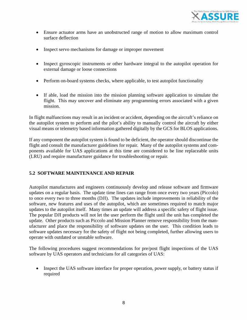
8
• Ensure actuator arms have an unobstructed range of motion to allow maximum control surface deflection
• Inspect servo mechanisms for damage or improper movement
• Inspect gyroscopic instruments or other hardware integral to the autopilot operation for external damage or loose connections
• Perform on-board systems checks, where applicable, to test autopilot functionality
• If able, load the mission into the mission planning software application to simulate the flight. This may uncover and eliminate any programming errors associated with a given mission.
In flight malfunctions may result in an incident or accident, depending on the aircraft’s reliance on the autopilot system to perform and the pilot’s ability to manually control the aircraft by either visual means or telemetry based information gathered digitally by the GCS for BLOS applications. If any component the autopilot system is found to be deficient, the operator should discontinue the flight and consult the manufacturer guidelines for repair. Many of the autopilot systems and com-ponents available for UAS applications at this time are considered to be line replaceable units (LRU) and require manufacturer guidance for troubleshooting or repair. 5.2 SOFTWARE MAINTENANCE AND REPAIR
Autopilot manufactures and engineers continuously develop and release software and firmware updates on a regular basis. The update time lines can range from once every two years (Piccolo) to once every two to three months (DJI). The updates include improvements in reliability of the software, new features and uses of the autopilot, which are sometimes required to match major updates to the autopilot itself. Many times an update will address a specific safety of flight issue. The popular DJI products will not let the user perform the flight until the unit has completed the update. Other products such as Piccolo and Mission Planner remove responsibility from the man-ufacturer and place the responsibility of software updates on the user. This condition leads to software updates necessary for the safety of flight not being completed, further allowing users to operate with outdated or unstable software. The following procedures suggest recommendations for pre/post flight inspections of the UAS software by UAS operators and technicians for all categories of UAS:
• Inspect the UAS software interface for proper operation, power supply, or battery status if required

9
• Physically inspect UAS Software interface connections to include power connections, data bus connections, and antenna or datalink connections
• Start the UAS software with an active internet connection (many software packages will automatically check for updates when first started)
• Verify software version number or release designation
• Ensure software version number or release designation matches the manufacture’s current released version (usually found on the manufacture’s website)
• Check the UAS software configuration is set for proper aircraft type or mode
• Ensure UAS software version matches the firmware version loaded on the autopilot
• Perform UAS software update if required
• Become familiar with UAS software changes after update
• Save or backup autopilot firmware configuration if autopilot firmware update is required
• Perform autopilot firmware update in accordance with manufactures instructions if re-quired
• Verify or load the firmware configuration after update to the configuration that was saved before update to ensure settings have not changed
5.3 ADDITIONAL MAINTAINER REQUIREMENTS FOR UAS TECHNOLOGIES
The results of the task 4civ analysis suggest maintainer requirements may require a broader under-standing of computing technologies, however, line maintenance or service is limited with most software and autopilot systems. The UAS technician is likely to troubleshoot onboard hardware in an effort to define operational deficiencies. Further maintenance or troubleshooting of autopilot hardware is most likely to be accomplished by the developer of each system, so the maintenance technician will only be required to replace the deficient hardware with a new system. The use of UAS GCS software ranges in user expertise. Systems such as those driven by Piccolo Cloud Cap technologies require the user to possess highly defined skill sets, where users of Mis-sion Planner software may require more limited training. The skill required to utilize UAS GCS software is often defined by the user’s ability to modify systems parameters, which is a result of the systems architecture design. Those with a CSA allow the user little ability to change or modify software elements, however the use of OSA allow the user much more freedom to access the sys-tems source code. With regard to systems updates, many systems, such as those developed by DJI, require the system to be updated with the latest firmware. Other systems that allow the user more
10
operational freedom may not have the same requirements, based on an expectation that the user holds a higher level of operational experience or expertise. Current maintenance at the component level for UAS autopilots and software suggests the mainte-nance technician has limited access to the internal components of a given system. However, future applications of UAS autopilot and software technologies will require the development of special-ized skills outlined by NCATT in Appendix D to support troubleshooting and repair. Maintainers and technicians will be required to posess the requisite knowledge from Appendix D in order to maintain a skill set congruent with UAS hardware and software applications..
11
6 Conclusions Maintainer and technician requirements for UAS autopilot and software applications vary greatly by system as a direct result of complexity. The functionality of the autopilot is heavily influenced by both the software and intended application of the system. Recommendations made as part of this report support the most up-to-date data available to the research team. Each of the systems analyzed represent similarities that define maintainer and technician requirements. Data represented throughout the appendices of this report indicate specific content areas for knowledge and skill required to properly maintain, service, or replace the majority of autopilot and software systems currently available. The development of further standards and protocols related to airworthiness and certification will likely confine manufacturers to stricter guidance regarding the operational characteristics and performance of these systems.

12
7 Definitions
Aircraft -A device that is used or intended to be used for flight in the air. Airframe - The fuselage, booms, nacelles, cowlings, fairings, airfoil surfaces (including rotors but excluding propellers and rotating airfoils of engines), and landing gear of an aircraft and their accessories and controls. Airworthy/Airworthiness -The UAS conforms to its type certificate (TC), if applicable, and has been determined to be in a condition for safe operation Airworthiness Statement - Letter from a public UAS applicant specifying self-certification of a UAS in compliance with the criteria of the public entity. Appliance - Any instrument, mechanism, equipment, part, apparatus, appurtenance, or accessory, including communications equipment, that is used or intended to be used in operating or control-ling an aircraft in flight, is installed in or attached to the aircraft, and is not part of an airframe, engine, or propeller. Autopilot – A device for automatically steering ships, aircraft, and spacecraft Appurtenance - Something subordinate to another, more important thing; adjunct; accessory. Beyond Visual Line of Sight (BVLOS) - Flightcrew members (i.e., remote pilot in com-mand (PIC), the person manipulating the controls, and visual observer (VO), if used) are not ca-pable of seeing the aircraft with vision unaided by any device other than corrective lenses (spec-tacles and contact lenses). Certificate of Waiver (CoW); Certificate of Authorization (CoA) - “certificate of waiver” and “certificate of authorization” mean a FAA grant of approval for a specific flight operation. Civil Aircraft- Aircraft other than public aircraft Control Station- An interface used by the remote pilot to control the flightpath of the small UA. The structure or system (ground, ship, or air-based) that controls the UAS and its interface to the aircraft and external systems. Cooperative Aircraft- Aircraft that have an electronic means of identification (i.e., a tran-sponder or Automatic Dependent Surveillance—Broadcast (ADS-B) transceiver) aboard in oper-ation. Crewmember (UAS) - A person assigned to perform an operational duty during operations. A UAS crewmember includes the remote PIC, person manipulating the controls, and VOs, but may include other persons as appropriate or required to ensure safe operation of the UAS. Daisy-Chaining- The use of multiple, successive VOs to extend the flight of a UA beyond the direct Visual Line of Sight (VLOS) of the PIC or VO.
13
Data Link- A wireless communication channel between one control station and one UA. Its util-ity may include, but is not limited to, uplink Command and Control (C2) data, downlink teleme-try, and payload data. A data link may consist of the following types:
• Uplink: The transmittal of data from the control station to the UA. • Downlink: The transmittal of data from the UA to the control station.
Direct Control- The capability of a remote pilot to manipulate the flight control surfaces of the aircraft in a direct fashion using, for example, a radio control box with joystick or a ground con-trol station using conventional type aircraft controls (such as a yoke/stick, rudder pedals, power levers, and other ancillary controls). This infers a one-to-one correspondence between control in-put and flight control surface deflection. External Pilot- A remote pilot who controls the UA from outside of an enclosure. Flight Termination- The intentional and deliberate process of terminating the flight in the event of lost link, loss of control, or other failure that compromises the safety of flight. Flyaway- An interruption or loss of the control link, or when the pilot is unable to effect control of the aircraft and, as a result, the UA is not operating in a predicable or planned manner because lost link procedures are not established or are not being executed by the UA. Formation Flight- Formation flying is the disciplined flight of two or more aircraft under the command of a flight leader in either standard or nonstandard formation. Human Factors- A term that covers the science of understanding the properties of human capa-bility, the application of this understanding to the design, development, and deployment of systems and services, and the art of ensuring successful application of human factor principles into the maintenance-working environment. Indirect Control- The capability of a remote pilot to affect the trajectory of the aircraft through computer input to an onboard flight control system. Internal Pilot- A remote PIC who flies from inside an enclosure and does not have VLOS with the aircraft. Lost Link- An interruption or loss of positive control between the control station and UA or when the pilot is unable to effect control of the aircraft. Lost link is not considered a flyaway. Lost Link Procedures- Preprogrammed or predetermined mitigations to ensure the continued safe operations of the UA in the event of lost link. In the event positive link cannot be achieved, flight termination must be implemented. Maintenance - Inspection, overhaul, repair, preservation, and the replacement of parts, but ex-cludes preventive maintenance.

14
Major Alteration - An alteration not listed in the aircraft, aircraft engine, or propeller specifica-tions
• That might appreciably affect weight, balance, structural strength, performance, pow-erplant operation, flight characteristics, or other qualities affecting airworthiness; or
• That is not done according to accepted practices or cannot be done by elementary op-erations.
Major Repair - A repair:
• That, if improperly done, might appreciably affect weight, balance, structural strength, performance, powerplant operation, flight characteristics, or other qualities affecting airworthiness; or
• That is not done according to accepted practices or cannot be done by elementary op-erations.
Minor Alteration - An alteration other than a major alteration. Minor Repair - A repair other than a major repair. Model Aircraft- Means a UA that is: (i) Capable of sustained flight in the atmosphere; (ii) Flown within VLOS of the person operating the aircraft; and (iii) Flown exclusively for hobby or recreational purposes. National Airspace System – The network of US airspace; airports; air navigation facilities; ATC facilities; communication, surveillance, and supporting technologies; and operating rules and reg-ulations. Its function is to provide a safe and efficient environment for civil, commercial and military aviation. Non-Cooperative Aircraft- Aircraft that do not have an electronic means of identification (e.g., a transponder) aboard or that have inoperative equipment because of malfunction or delib-erate action. Off-Airport- Any location used to launch or recover aircraft that is not considered an airport (e.g., an open field). Operator - Any person who causes or authorizes the operation of an aircraft, such as the owner, lessee, or bailee of an aircraft. Optionally Piloted Aircraft (OPA) - A manned aircraft that can be controlled by a remote pilot from a location not onboard the aircraft. An aircraft having UAS technology and retains the capa-bility of being flown by a Pilot Onboard (PO) using conventional control methods. Person Manipulating the Controls- A person who is controlling a sUAS under the direct super-vision of a remote PIC. Propeller - a device for propelling an aircraft that has blades on an engine-driven shaft and that, when rotated, produces by its action on the air, a thrust approximately perpendicular to its plane

15
of rotation. It includes control components normally supplied by its manufacturer, but does not include main and auxiliary rotors or rotating airfoils of engines. Remote Pilot in Command Certification (Remote PIC). A person who holds a remote pilot certificate with a small Unmanned Aircraft Systems (sUAS) rating and has the final authority and responsibility for the operation and safety of a sUAS operation conducted under 14 CFR part 107. Scheduled Maintenance (Routine) - The performance of maintenance tasks at prescribed inter-vals. Small Unmanned Aircraft- A UA weighing less than 55 pounds on takeoff, including every-thing that is onboard or otherwise attached to the aircraft. Small Unmanned Aircraft System (sUAS) - A small UA and its associated elements (including communication links and the components that control the small UA) that are required for the safe and efficient operation of the small UA in the NAS (including launch and recovery systems and equipment). Special Airworthiness Certificates- A “special airworthiness certificate” used for all aircraft that are certificated in categories other than standard. Tethered UAS- A UA that is restrained by a cable and attached to the ground or an object thereon. Time in service, with respect to maintenance time records, means the time from the moment an aircraft leaves the surface of the earth until it touches it at the next point of landing. Unmanned Aircraft (UA) - An aircraft that is operated without the possibility of direct human intervention from within or on the aircraft. Unmanned Aircraft System (UAS) - A UA and associated elements (including communication links and the components that control the UA) that are required for the remote PIC to operate safely and efficiently in the NAS. Unscheduled Maintenance (Non-routine) - The performance of maintenance tasks when me-chanical irregularities occur. Visual Line of Sight (VLOS) - Any flightcrew member (i.e., remote PIC, the person manipulat-ing the controls, and visual observer, if used) is capable of seeing the aircraft with vision unaided by any device other than corrective lenses, spectacles or contact lenses in order to know the UA’s location, determine the UA’s attitude, altitude, and direction of flight, observe the airspace for other air traffic or hazards, and determine that the UA does not endanger the life or property of another.
16
Visual Observer (VO) - A person who is designated by the PIC to assist the remote PIC and the person manipulating the flight controls of the sUAS to supplement situational awareness and Vis-ual Line of Sight (VLOS), assisting with seeing and avoiding other air traffic or objects aloft or on the ground. The visual observer (VO) must be able to effectively communicate:
• The small UA location, attitude, and direction of flight; • The position of other aircraft or hazards in the airspace; and • The determination that the UA does not endanger the life or property of another.
17
8 Acronyms AC – Alternating Current ADS – Air Data System AFM – Aircraft Flight Manual ARNAV – Area Navigation ASTM – American Society for Testing and Materials BLOS – Beyond Line of Sight CAS – Closed Architecture System CPU – Central Processing Unit CWS – Control Wheel Steering DC – Direct Current DoD – Department of Defense GCS – Ground Control Station GPS – Global Positioning System IAS – Indicated Airspeed INS – Inertial Navigation System I/O – Input/Output ISD – Interface Control Definition ISO – International Standard Organization LAN – Local Area Network LNAV – Lateral Navigation LPV – Localizer Performance with Vertical Guidance LRS – Long Range Surveillance

18
LRU – Line Replaceable Unit MAN – Metropolitan Area Network MIL – Military Standard NATO – North American Treaty Organization NCATT – National Center for Aerospace & Transportation Technologies OAS – Open Architecture System OSI – Open-Systems Interconnect TCP/IP – Transmission Control Protocol/Internet Protocol VPN – Virtual Private Network WAN – Wide Area Network

19
9 References AeroQuad. (2017). AeroQuad Software. Retrieved January 3, 2017, from http://aeroquad.com/showwiki.php?title=AeroQuad-Software Airnest, (2017). Simple Flight Logging & Analytics for Drones. Retrieved January 16, 2017, from http://www.airnest.com/ ArduPilot. (2017a). Ardupilot Autopilot Suite. Retrieved January 4, 2017, from http://ardupi-lot.org/ardupilot/index.html ArduPilot. (2017b). Mission Planner Home. Retrieved January 15, 2017, from http://ardupi-lot.org/planner/ ASTM. (2014). ASTM Standardization News. Retrieved January 10, 2017, from https://www.astm.org/standardization-news/?q=update/operations-standards-for-small-un-manned-aircraft-systems-mj14.html&gateway=Transportation%2520&%2520Infrastructure Autoquad. (2017). Autoquad Project Timeline. Retrieved January 10, 2017, from http://au-toquad.org/home/autoquad-project-timeline/ Cloud Cap Technology. (2017). Piccolo Autopilots. Retrieved January 11, 2017, from http://www.cloudcaptech.com/products/auto-pilots/ DJI. (2017a). NAZA-M V2. Retrieved January 13, 2017, from https://www.dji.com/naza-m-v2 DJI. (2017b). DJI Go Application. Retrieved January 15, 2017, from http://www.dji.com/goapp dRonin. (2017) Advanced Flight Control. Retrieved January 17, 2017, from http://dronin.org/ Emlid. (2017). Navio2 Linux Autopilot on Raspberry Pi. Retrieved January 11, 2017, from https://emlid.com/navio/ LibrePilot. (2017). Openpilot. Retrieved January 12, 2017, from https://www.librepilot.org/site/in-dex.html Litchi. (2017). Litchi. Retrieved January 16, 2017, from https://flylitchi.com/ Lockheed Martin. (2017). Kestrel Flight Systems & Autopilot. Retrieved January 13, 2017, from http://www.lockheedmartin.com/us/products/procerus/kestrel-autopilot.html MatrixPilot. (2017). MatrixPilot Info. Retrieved January 15, 2017, from https://github.com/Ma-trixPilot/MatrixPilot/wiki/MatrixPilot MicroPilot. (2017). Micropilot Autopilot Series. Retrieved January 13, 2017, from https://www.micropilot.com/

20
NCATT. (2017a). Unmanned Aircraft System (UAS) Maintenance Standard. Retrieved February 3, 2017, from http://www.lcis.com.tw/paper_store/paper_store/UAS_Maintenance_Standard-201542521537750.pdf NCATT. (2017b). Aircraft Electronics Technician (AET) Standard. Retrieved February 3, 2017, from https://www.astm.org/CERTIFICATION/DOCS/217.NCATT_AET_Standard.pdf Paparazzi. (2017) Paparazzi Autopilots. Retrieved January 14, 2017, from http://wiki.paparazzi-uav.org/wiki/Category:Autopilots Pixhawk. (2017a). PX4 Autopilot, Retrieved January 14, 2017, from http://px4.io/ Pixhawk. (2017b). 3DR Pixhawk Mini. Retrieved January 14, 2017, from https://store.3dr.com/products/3dr-pixhawk Pixhawk. (2017c). Pixracer Autopilot. Retrieved January 14, 2017, from https://pixhawk.org/mod-ules/pixracer Rockwell Collins. (2017a). Athena 111. Retrieved January 10, 2017, from https://www.rockwell-collins.com/Products_and_Services/Defense/Navigation/Airborne_Products/Attitude_and_Head-ing_Reference_System/Athena_111_Integrated_Flight_Control_System.aspx Rockwell Collins. (2017b). Athena 511. Retrieved January 10, 2017, from https://www.rockwell-collins.com/Products_and_Services/Defense/Navigation/Airborne_Products/Attitude_and_Head-ing_Reference_System/Athena_511_Integrated_Flight_Control_System.aspx SenseFly. (2017) Emotion Flight Planning & Control Software. Retrieved January 15, 2017, from https://www.sensefly.com/software/emotion-2.html SLUGS. (2017). Santa Cruz Low-Cost UAV GNC System. Retrieved January 13, 2017, from https://slugsuav.soe.ucsc.edu/ SmartAp. (2017). Advanced UAVs & Flight Control Systems. Retrieved January 14, 2017, from http://sky-drones.com/
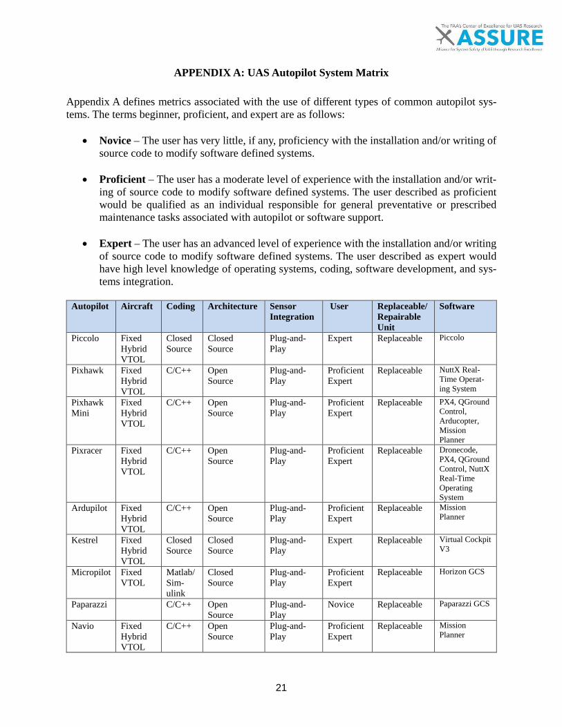
21
APPENDIX A: UAS Autopilot System Matrix Appendix A defines metrics associated with the use of different types of common autopilot sys-tems. The terms beginner, proficient, and expert are as follows:
• Novice – The user has very little, if any, proficiency with the installation and/or writing of source code to modify software defined systems.
• Proficient – The user has a moderate level of experience with the installation and/or writ-ing of source code to modify software defined systems. The user described as proficient would be qualified as an individual responsible for general preventative or prescribed maintenance tasks associated with autopilot or software support.
• Expert – The user has an advanced level of experience with the installation and/or writing of source code to modify software defined systems. The user described as expert would have high level knowledge of operating systems, coding, software development, and sys-tems integration.
Autopilot Aircraft Coding Architecture Sensor
Integration User Replaceable/
Repairable Unit
Software
Piccolo Fixed Hybrid VTOL
Closed Source
Closed Source
Plug-and-Play
Expert Replaceable Piccolo
Pixhawk Fixed Hybrid VTOL
C/C++ Open Source
Plug-and-Play
Proficient Expert
Replaceable NuttX Real-Time Operat-ing System
Pixhawk Mini
Fixed Hybrid VTOL
C/C++ Open Source
Plug-and-Play
Proficient Expert
Replaceable PX4, QGround Control, Arducopter, Mission Planner
Pixracer Fixed Hybrid VTOL
C/C++ Open Source
Plug-and-Play
Proficient Expert
Replaceable Dronecode, PX4, QGround Control, NuttX Real-Time Operating System
Ardupilot Fixed Hybrid VTOL
C/C++ Open Source
Plug-and-Play
Proficient Expert
Replaceable Mission Planner
Kestrel Fixed Hybrid VTOL
Closed Source
Closed Source
Plug-and-Play
Expert Replaceable Virtual Cockpit V3
Micropilot Fixed VTOL
Matlab/Sim-ulink
Closed Source
Plug-and-Play
Proficient Expert
Replaceable Horizon GCS
Paparazzi C/C++ Open Source
Plug-and-Play
Novice Replaceable Paparazzi GCS
Navio Fixed Hybrid VTOL
C/C++ Open Source
Plug-and-Play
Proficient Expert
Replaceable Mission Planner

22
Openpilot Fixed VTOL
C/C++ Open Source
Plug-and-Play
Proficient Expert
Replaceable Openpilot GCS
Aeroquad VTOL C/C++ Open Source
Plug-and-Play
Novice Replaceable dRonin AeroQuad
Athena 111
Fixed Hybrid VTOL
Proprie-tary
Closed Source
Plug-and-Play
Expert Replaceable Proprietary
Athena 511
Fixed Closed Source
Closed Source
Plug-and-Play
Expert Replaceable Proprietary
Slugs Matlab/Sim-ulink
Open Source
Plug-and-Play
Proficient Expert
Replaceable Autoquad GCS
Matrix- pilot
Fixed C/C++ Open Source
Plug-and-Play
Proficient Expert
Replaceable QGround Control
Smartap VTOL Closed Source
Closed Source
Plug-and-Play
Expert Replaceable SmartAP GCS
Autoquad Fixed VTOL
C/C++ Closed Source
Plug-and-Play
Proficient Expert
Replaceable Autoquad GCS
NAZA VTOL Closed Source
Closed Source
Plug-and-Play
Novice Replaceable DJI go
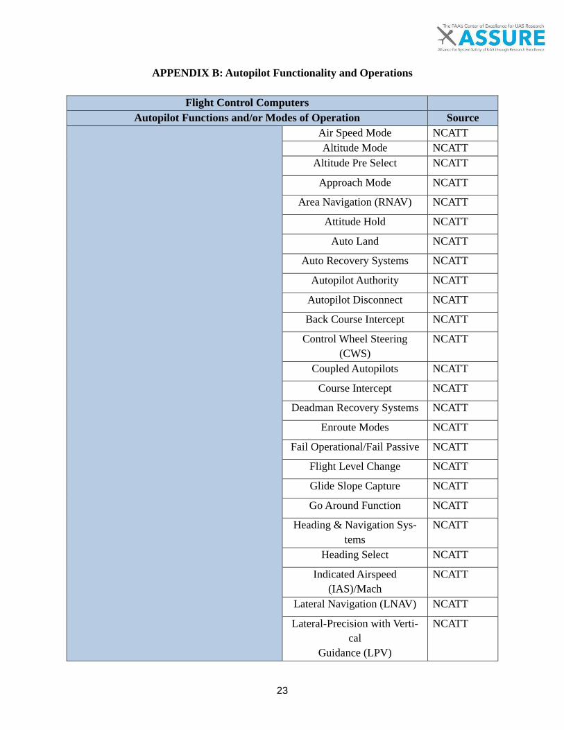
23
APPENDIX B: Autopilot Functionality and Operations
Flight Control Computers Autopilot Functions and/or Modes of Operation Source
Air Speed Mode NCATT Altitude Mode NCATT
Altitude Pre Select NCATT
Approach Mode NCATT
Area Navigation (RNAV) NCATT
Attitude Hold NCATT
Auto Land NCATT
Auto Recovery Systems NCATT
Autopilot Authority NCATT
Autopilot Disconnect NCATT
Back Course Intercept NCATT
Control Wheel Steering (CWS)
NCATT
Coupled Autopilots NCATT
Course Intercept NCATT
Deadman Recovery Systems NCATT
Enroute Modes NCATT
Fail Operational/Fail Passive NCATT
Flight Level Change NCATT
Glide Slope Capture NCATT
Go Around Function NCATT
Heading & Navigation Sys-tems
NCATT
Heading Select NCATT
Indicated Airspeed (IAS)/Mach
NCATT
Lateral Navigation (LNAV) NCATT
Lateral-Precision with Verti-cal
Guidance (LPV)
NCATT

24
Radar Altimeter/Trip Points NCATT
Terrain Following Mode NCATT
Vertical Navigation NCATT
Vertical Speed Mode NCATT
Flight Management System Install/Update Databases NCATT
Navigation sensors NCATT
Powerplant Sensors NCATT
Fuel Sensors NCATT
Airframe Sensors NCATT
Flight Management System Integration Nav Radio Tuning NCATT
Flight/Nav Guidance NCATT
Global Positioning System (GPS)
NCATT
Long Range Surveillance (LRS)
NCATT
Inertial Navigation System (INS)
NCATT
Lost Link & Flight Recovery NCATT
Digital Data Bus Theory Data Information NCATT
Address Information NCATT
Control Information NCATT
ARINC 429 Specification (Digital Data Transfer)
NCATT
Air Data Bus System Air Data Bus Sensors NCATT
Air Data Bus NCATT
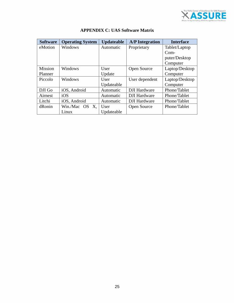
25
APPENDIX C: UAS Software Matrix
Software Operating System Updateable A/P Integration Interface eMotion Windows Automatic Proprietary Tablet/Laptop
Com-puter/Desktop Computer
Mission Planner
Windows User Update
Open Source Laptop/Desktop Computer
Piccolo Windows User Updateable
User dependent Laptop/Desktop Computer
DJI Go iOS, Android Automatic DJI Hardware Phone/Tablet Airnest iOS Automatic DJI Hardware Phone/Tablet Litchi iOS, Android Automatic DJI Hardware Phone/Tablet dRonin Win./Mac OS X,
Linux User Updateable
Open Source Phone/Tablet
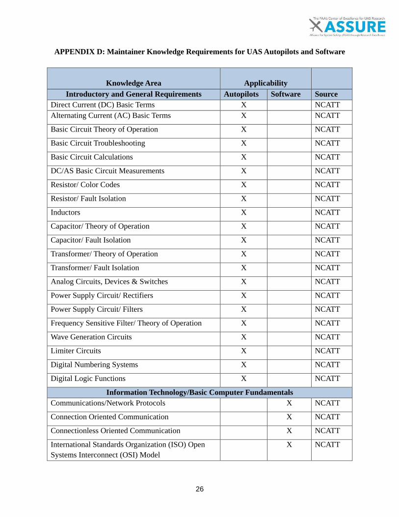
26
APPENDIX D: Maintainer Knowledge Requirements for UAS Autopilots and Software
Knowledge Area
Applicability
Introductory and General Requirements Autopilots Software Source Direct Current (DC) Basic Terms X NCATT Alternating Current (AC) Basic Terms X NCATT
Basic Circuit Theory of Operation X NCATT
Basic Circuit Troubleshooting X NCATT
Basic Circuit Calculations X NCATT
DC/AS Basic Circuit Measurements X NCATT
Resistor/ Color Codes X NCATT
Resistor/ Fault Isolation X NCATT
Inductors X NCATT
Capacitor/ Theory of Operation X NCATT
Capacitor/ Fault Isolation X NCATT
Transformer/ Theory of Operation X NCATT
Transformer/ Fault Isolation X NCATT
Analog Circuits, Devices & Switches X NCATT
Power Supply Circuit/ Rectifiers X NCATT
Power Supply Circuit/ Filters X NCATT
Frequency Sensitive Filter/ Theory of Operation X NCATT
Wave Generation Circuits X NCATT
Limiter Circuits X NCATT
Digital Numbering Systems X NCATT
Digital Logic Functions X NCATT
Information Technology/Basic Computer Fundamentals Communications/Network Protocols X NCATT
Connection Oriented Communication X NCATT
Connectionless Oriented Communication X NCATT
International Standards Organization (ISO) Open Systems Interconnect (OSI) Model
X NCATT

27
Transmission Control Protocol/Internet Protocol (TCP/IP)
X NCATT
Department of Defense (DoD) Standards Protocol X NCATT
IPV4/IPV6 X NCATT
Components X NCATT
Central Processing Unit (CPU) X NCATT
Computer Memory X NCATT
Input/Output (I/O) Devices X NCATT
Storage Devices X NCATT
Peripherals (Printers, FAX, Scanners, etc) X NCATT
Network Types; (LAN, MAN, WAN) X NCATT
Wireless X NCATT
Virtual Private Network (VPN) X NCATT
Topologies (Star, Ring, Bus, Hybrid, etc) X NCATT
Data Terminal Equipment/Data Communications Equipment
X NCATT
Modems X NCATT
Converters X NCATT
Gateway Multiplexing X NCATT
Wave Division Multiplexing X NCATT
Time Division Multiplexing Switches X NCATT
Bridges/Routers X NCATT
Encryption X NCATT
Communication Mediums X NCATT
Software X NCATT
Operating systems X NCATT
Applications X NCATT
Bulk Encryption X NCATT
Information Encryption Techniques X NCATT
Network Error Detection X X NCATT
Network Error Correction X X NCATT

28
Network Flow Control X X NCATT
Cyber Vulnerabilities X NCATT
Vulnerability Preventative Measures X NCATT
Identity Management X NCATT
Wireless Network Security X NCATT
Common Maintenance Practices Hazards/Safety Practices X NCATT
Hazardous Materials Handling X NCATT
Technical Publications X X NCATT
Fundamentals of On-Equipment Maintenance Use Common Tools X NCATT
Handling Electrostatic Devices X NCATT
Identify & Perform Corrosion Control X NCATT
Use Safety Devices X NCATT
Aircraft Wiring X NCATT
Perform Wire Maintenance X NCATT
Use Test Equipment/Special Tools X NCATT
Aircraft Fundamentals Aircraft Structures X NCATT
Aircraft Handling and Safety X X NCATT
LAN – Local Area Network Theory Multiplexing/De-multiplexing NCATT
Hubs NCATT
IP Signal Flow/Data Transfer X NCATT
Long Haul Communication/WAN X NCATT
Processors X X NCATT
Programming Languages (C, C+, C++, Python, etc.) X X NCATT
Routers X NCATT
Sensors X X NCATT
Telecommunication switches X NCATT

29
Ground Station Maintenance Rack Reset (Soft vs. Hard Reboot) X NCATT
Software Use/Manipulation X NCATT
UA Control X NCATT
Data Logger Download X NCATT
Software Upload X NCATT
Periodic Maintenance Inspection X NCATT
Signal Flow Flight Control Computers X X NCATT
Autopilot Functions and/or Modes of Operation X X NCATT
Flight Management Systems X X NCATT
Flight Management System Integration X X NCATT
Digital Data Bus Theory X X NCATT