a ui m u alves n in
TRANSCRIPT

A GUIDE TO THERMAL SHUT-OFF VALVES
FOR PLANT PROTECTION
thermal shut-off overviewregulations and guidelines
theory of operationplacement principles
protection typesapplications
typical layoutsaccessories and customizations
09/11/2019

page 2 of 11 bi-torq valve automation - thermal shut-off guide www.bitorq.com
Modern facilities take a multi-faceted approach towards fire safety. This approach mitigates the risk through prevention, containment and suppression. In the area of containment, BI-TORQ’s FLP/FL series thermal shut-off valves, also known as fusible link valves or emergency shutdown valves, are the solution of choice for tank and pipeline isolation.
A TSV consists of two main parts, a API 607 fire safe valve and the thermal shut-off topworks. The thermal shut-off actuator (topworks) assembly, consists of a spring pack, arming/firing assembly, and valve mounting hardware. When all this is paired together, you get a fire safety device that is low maintenance and a true isolation valve - ensuring flow will be contained in the event of a fire. The assemblies can also be used manually to isolate a tank or pipeline section for maintenance.
WHY YOU NEED A TSV
The strategic placement of thermal shut-off valves (TSVs) helps maximize a facility’s overall fire safety program three ways.
Thermal shut-off valves used at the tank level will isolate tanks and keep flammable or hazardous media at their source, keeping their content from getting down stream and escalating a fire or creating another hazard for emergency responders, if the media is toxic. Knowing that the media is isolated also allows emergency responders to be able to assess a situation better. This is why placement should be closest to the tank outlet when possible.
When placed at critical junctures in a piping system, the flow stoppage from an activated assembly will keep pipe contents from getting free in buildings or at other key points in the system due to ruptured pipes, broken fittings or other leak points in the system.
Keeping flammable or toxic media contained automatically - taking the human factor out of the loop - also has the benefit of keeping it from being released to the general public via a vapor cloud or getting into the ground water system. The human factor pertains to closing manual valves or having to initiate a sequence from a control panel.
THERMAL SHUT-OFF VALVE (TSV) OVERVIEW
37,000the number of industrial fires per year
18 deaths279 injuries
$1 billion in damagesAccording to most recent fire statistic from the
National Fire Protection Association (NFPA)
KEY FEATURES
The biggest key feature of a BI-TORQ Thermal Shut-off Valve is its FM approval, available on models through 3,960 in/lbs of torque). Whether FM Global is your insurance carrier or not, the approval signifies that a rigorous series of tests were done and certified by a global leader in loss prevention, ensuring performance when it counts.
BI-TORQ offers the largest thermal shut-off assembly of its kind in the industry with a maximum valve torque of up to 21,390 in/lbs, or enough for a 20-24” butterfly valve, depending on pressure differentials and application.
Our TSVs are offered 2 ways - as a complete package with fire safe valve (FLP series) or as a thermal shut-off actuator only, to be fitted at our facility to a customer-specified or AML valve (FL series).
Optional features include continuous position feedback and environmental packages. The assemblies are also installation friendly to accommodate possible obstructions. We also offer the ability to remote fire with an electrical signal (TES series1) or the ability to fire multiple ways and test regularly, maximizing safety (R-EBV series1).
FL series with Fire Safe BFV
FLP series with BI-TORQ FW Series BV
1 non-fm approved series

page 3 of 11 bi-torq valve automation - thermal shut-off guide www.bitorq.com
BI-TORQ Valve Automation’s API 607 fire safe valves use a combination of a floating ball, graphoil seals and secondary metal-to-metal seating to ensure tight shut-off while preventing external stem leakage after the original seat is compromised in a fire.
Under normal working conditions, the floating ball rests against one of two seats, typically PTFE or RTFE, ensuring bubble-tight closure. When the valve is exposed to temperature above the limits the seats can withstand (for example, +450 F), the seat becomes deformed and is subject to extrusion. When the seats have been totally destroyed, the ball will come to rest firmly against the body end cap, producing a metal-to-metal seal or closing. Graphoil body and stem seals, which have high temperature-resistant properties, further restrict leakage in conjunction with a blow-out proof anti-static stem, ensuring that the valve will perform to international API 607 standards.
REGULATIONS AND GUIDELINES
Factory Mutual (FM) standard 7440 is the standard on which our thermal shut-off assemblies are tested to. It is a stringent series of tests and checks, including a fire test.
OSHA guidelines - Industrial and Building Regulations 1926.152(i)(4)(iv)(C) - stipulates use of a thermal shut-off valve for flammable liquid tanks located inside buildings
GAPS guidelines – Global Asset Protection Services has GAP.8.1.0 for Flammable and Combustible liquids and involves a section on Process Facilities, Dispensing, Handling, Transfer, and Use of Liquids. They also wrote GAP.8.0.1.3 specifically to address Emergency Block Valves.
American Petroleum Institute (API) has RP 553 which details Emergency Block Valve types. They also have their standard 607 defining the standard on what a fire safe valve is and how it is tested.
There are numerous regulations and guidelines for the installation of thermal shut-off valves, also known as fusible link valves or emergency block valves. A few of the concrete ones that would pertain to flammable or toxic storage tanks include ones from FM Global, GAPS, API and OSHA.
API 607 FIRE SAFE VALVE PRINCIPLES

page 4 of 11 bi-torq valve automation - thermal shut-off guide www.bitorq.com
THERMAL SHUT-OFF THEORY OF OPERATION
1. Fusible links melt at designated temperature
2. Locking trigger separates from fusible link retaining rod and rotates away
3. Locking trigger releases spring stop assembly
4. Clock wound spring pack is freed and unwinds
5. Spring rotates extended coupler 90 degrees
6. Valve shaft rotates to the closed position
4
5
6
BALL VALVES WITH TORQUE UP TO 830 IN/LBS
The valve can be manually operated even when armed. Handle parallel to pipeline.
Clock spring releases and drives tripper arm to close valve via handle.
API 607 fire safe design prevents flow with valve in closed position.
Armed unit withvalve in open position
Fusible link breaks at rated temperature
Handle at valve stop: valve in closed position
BUTTERFLY VALVES AND LARGER BALL OR PLUG VALVES
A declutch gear override is used due to larger torques.Units must be disarmed (links not under tension) before manual
operation can occur.
1
2
3

page 5 of 11 bi-torq valve automation - thermal shut-off guide www.bitorq.com
Placement of Thermal Shut-off Valves at critical junctures in pipelines is crucial in keeping the potential for fire acceleration down. Each facility is different than the next, but the commonalities for placement consideration would include breaking up long pipe runs, adding TSVs to key piping branches to create choke points and installing them on pipeline high and low points.
PLACEMENT PRINCIPLESFOR TANK PROTECTIONOne of the primary functions of a thermal shut-off valve is tank protection. Keeping the flammable contents of tanks, large or small, from feeding a fire downstream is a key fire safety strategy. Placement for TSVs at tanks is simple - place one at each tank outlet and as close to the tank as possible. On larger sized outlets, a manual gate valve may be considered just before a thermal shut-off valve for maintenance purposes.
INSTALLATION IN BUILDINGSBuildings also offer more chances for pipeline breaks due to spaces being more crowded. They are also harder to access for First Responders so key placement of TSVs is a beneficial strategy. Installing TSVs just before a flammable line enters a building through a wall or just as they come through a floor will minimize the potential for product to escalate a fire. The next three placement principles will also play a big part in building installation strategies.
VENTING
STRATEGIC JUNCTURES
Thermal Shut-off Valves can be installed on top of tanks to prevent tank collapse in the event of a fire. Proper sizing should be considered and the units would need to would be ordered as fail open units.
FANNING MEDIAIsolating hoses or hard piped media like compressed air or nitrogen lines will keep those lines from helping a fire spread. An additional concern is that during a fire, hydraulic lines can rupture and further fuel the fire. Under high pressure the release of flammable fluid can atomize and spray, creating a torch-like effect upon ignition. Depending on the type of rupture, hose material and pressures involved, the length of the directed flame can be up to 20 feet long. This coupled with the erratic motion of the ruptured lines greatly compounds an already dangerous situation.
PUMPSTaking pressured and flowing flammable lines out the equation is critical in mitigating the escalation of a fire and keeping the risk to personnel to a minimum. Depending on your setup, a thermal shut-off valve on either the suction or discharge side of the pump is recommended. The key principle here is that a position feedback option is recommended on either type of installment. This would help avoid deadheading or running the pumps dry if the TSVs are tripped and close.

page 6 of 11 bi-torq valve automation - thermal shut-off guide www.bitorq.com
1. THERMAL SHUT-OFF (FLP/FL): “sentry-type” protection for local isolation. FM approved option.
2. THERMAL-ELECTRIC (TES): Local thermal protection coupled with the ability to close 1 or more units with a low voltage remote signal for greater plant protection.
3. RE-SETTABLE BLOCK VALVE (R-EBV): Local and remote protection as well as the ability to quickly test regularly as part of a maintenance program, ensuring valves are not frozen in place.
4. FUSIBLE PLUGS: Offers the cost-effective ability to retrofit and add a simple additional safety tier to pneumatic spring return actuators throughout a plant.
PROTECTION TYPES
EITHER OPTION WITHFACTORY MUTUAL APPROVAL
THROUGH 3,960 IN/LBS OF TORQUE
BI-TORQ Valve Automation offers 4 ways to protect a full facility. All types are available as fail open or fail close units.
THERMAL SHUT-OFF SERIES (FLP/FL)
MODEL BREAKDOWNFLP SERIES
BI-TORQ offers a wide range of API 607 ball valves from 1/2” through 6” in stainless or carbon steel. In addition, butterfly valves are available from 2” through 24” NPS.1
a complete package
BI-TORQ has factory-mounted our thermal shut-off topworks/actuator on a wide range of customer-supplied API 607 ball, butterfly valves, and plug valves from 1/4” through 24” NPS.1
FL SERIESyour specified valve
• 78 through 155 in/lbs of torque• Manual use while armed• FM approved• Ball valves only
LT SERIES: model 059
• 156 through 830 in/lbs of torque• Manual use while armed (BVs only)• FM approved
MT SERIES: models 079,089, & 099
• 831 through 1,810 in/lbs of torque• FM approved
HT SERIES: models 109 & 129
• 1,811 through 21,390 in/lbs of torque• 149X only model FM approved (3,960 in/lbs)
BT SERIES: models 149X, 149, 169X, 157, 169, & 189
FLP-HT series with a BI-TORQ ED50 series
Fire Safe BV
1 dependent on pressure differential and application

page 7 of 11 bi-torq valve automation - thermal shut-off guide www.bitorq.com
RE-SETTABLE EMERGENCY BLOCK VALVE
THERMAL-ELECTRIC SERIES (TES)Our Thermal-Electric Series provide the ability to shut down tank or piping section in advance of an encroaching fire. A low-voltage DC signal to the thermal-electric link will initiate a chemical reaction that causes the link to separate, releasing the spring pack. The low-voltage DC signal allows the TES to be wired up to a fire detection system. The links are also triggered by local heat or fire, making this series an ideal solution for indoor only applications. The links are available in two temperatures - 165°F and 212°F.
• 1/4” through 6” ball valves• 2” through 12” high performance butterfly valves• 6,000 PSI high pressure NPT ball valves• Customer specified valves up to 3,960 in/lbs of torque
SIZE RANGE
AUTOMATED VALVES WITH FUSIBLE PLUGSOur standard automated fire safe valves with pneumatic actuators can be outfitted with fusible plugs for a cost-effective way to add safety to other areas of the plant for extra protection, but where a full Thermal Shut-off can’t be fitted into a piping system. The fusible plugs along with tee are available in stainless steel or brass construction. BI-TORQ also offers stainless steel rack & pinion actuators for corrosive environments. The plugs are available in two temperatures - 165°F and 212°.
BI-TORQ’s Re-Settable Emergency Block Valve (R-EBV) is designed for critical applications in refineries, natural gas production pipelines, chemical facilities, or any other process involving flammable liquids or gases. The R-EBV will shut down an API 607 1/4 turn valve due to local high heat(flame or ambient), reducing chances that dangerous media will further feed a fire. The unit can also be shut down with a remote signal in advance of an approaching emergency situation. In addition to those safety features, the R-EBV can be easily tested by a sinlge operator as part of a regular maintenance program, ensuring functionality. Other features include a dashpot to control closing speed and a modular design for easy maintenance.
• Fusible plug on pneumatic actuator• Remote signal to a limit switch• Declutchable manual override• Local pushbutton solenoid
SHUTDOWN VIADesigned to be mounted to valves on an AML or other customer-specified
fire safe valves
• Carbon or stainless steel bodies• 1/4” through 2” NPT or SW ends• 1/2” through 6” in ANSI 150# flanges
FIRE SAFE VALVE OPTIONS
PROTECTION TYPES
Uses a 6-30 VAC-DC signal with a .2 amp trip current (50 millisecond minimum).
Link will separate in 6-10 seconds
Fusible Plug
air inlet

page 8 of 11 bi-torq valve automation - thermal shut-off guide www.bitorq.com
Diesel Day Tank
Fire PumpDiesel Tank
Diesel FirePump
Fire PumpDiesel Tank
Diesel Boiler
TankVent
TankVent
SAGMill
BackupGenerator
building wall
PLACEMENT IN A DIESEL SYSTEM
NOTES
1. A position feedback option is recommended on the discharge and suction side of the pumps to avoid deadheading or running them dry if they are triggered. Only one TSV is typically used on a pump.
2. For tank outlets larger than 4” diameter, a TSV with BFV maybe be considered.
BI-TORQ Valve Automation’s thermal shut-off valves (FLP series) are designed to provide critical shutdown protection in piping systems with flammable media. Ideal placement is on the outlets of flammable storage tanks or at critical point in where flow needs to be stopped. For full system protection, a variety of valves sizes will be used utilizing our LT, MT, HT, and BT series thermal shut-off valves.

page 9 of 11 bi-torq valve automation - thermal shut-off guide www.bitorq.com
VacuumDistillation
AtmosphericDistillation
Coking
DistillateHydrotreating
NaphthaHydrotreating
CatalyticReforming
VGOHydrotreating
IsomerizationLPG
GasolineAromatics
Jet Diesel
Gasoline
Hydrocracking
PetroleumCoke
Asphalt
Jet
Diesel
Bottoms to FCC,Lube Plant,or Recycle
FCC
Coker Gas Oil to FCCor Hydrocracker
VacuumGas Oil
Gasoline
Ole�ns to Alkylation or Ole�ns Plant
Cycle Oil to Blending, Hydrotreatingor Hydrocracking
Hydrogen
Hydrogen
CrudeStorage
PLACEMENT IN A REFINERY
A refinery’s complexity creates a unique blend of challenges in regards to fire safety. A mix of two types of thermal shut-off valves are used - FLP and R-EBV series. The use of the R-EBV is for applications where testing of the valve to ensure functionality is most critical, hydrogen and LNG lines should be considered for the R-EBV.

page 10 of 11 bi-torq valve automation - thermal shut-off guide www.bitorq.com
INSTALLATION CONSIDERATIONS
HANDWHEEL LOCATION IS MAXIMUM DISTANCE FROM TANK IN DEFAULT “D”
VERTICAL ORIENTATION
STANDARD BALL VALVE ORIENTATION
WITH HORIZONTAL AUXILIARY SUPPORTS
(PROVIDED BY OTHERS)
BI-TORQ Valve Automation’s HT Series and BT Series ball valve assemblies, as well as all butterfly valve assemblies utilize a declutchable gear override with handwheel to arm and manually operate the assemblies. Handwheel position, installation orientation, and overall dimensions should be taken into consideration when ordering any assembly, particularly when mounting near a tank or in parallel piping situations.
Our standard and default orientation is with the handwheel furthest downstream in relation to the gear shaft position on the override. As an alternative for parallel piping or other considerations, we can rotate the declutchable gear override 180 degrees during manufacturing. Rotation should NOT be done in the field.
We also recommend that all assemblies using our BT-149X spring pack and larger be mounted vertically. In instances where this is not possible and the assembly needs to be installed horizontally, auxiliary supports MUST be used to support the spring pack.
TANKTOP VIEW
C
B
A
TANKTOP VIEW
F
E
D
NOTE: VALVE MOUNTED VERTICALLY
FLOWFLOW
HANDWHEEL ORIENTATIONS
NOTE
1. In cases where handwheel size is an issue, whether it is hitting the tank or other piece of equipment, we can look at a different options to find a solution. Please consult your local BI-TORQ representative.

page 11 of 11 bi-torq valve automation - thermal shut-off guide www.bitorq.com
APPLICATIONSWe design our fusible link thermal shut-off valves to meet a variety of applications, including:
flp installation at an engineered rubber facility
r-ebv about to be installed on a hydrosphere • Oxygen lines• LNG3
• Hydrogen• Paints2
• Solvents• Alcohol
• Adhesives• Sealants• Ethanol• Jet Fuel• Diesel/Gasoline• Oil
• Water1
• Foam1
BY MEDIA TYPE
• Tank farms• Airports• Biodiesel plants• Fire suppression systems1
• Bulk loading/unloading• Petrochemical plants
• Refineries• Fracking• Pumps• Backup generators• Day tanks• Marine refueling
fl series on a bulk loading station
NOTES
1. Fail open spring pack models. TES models can be considered to tie into a fire alarm system.
2. All BI-TORQ fire safe valves are silicone free for paint applications.
3. A typical use for our R-EBV series
fl series with fire safe plug valve

page 12 of 16 bi-torq valve automation - thermal shut-off guide www.bitorq.com
1. SCOPE
1.1. This specification covers the standards, design, and manufacture of the FLP series thermal shut-off ball valve packages from BI-TORQ Valve Automation.
2. STANDARDS
2.1. The thermal shut-off actuator assembly (topworks) portion shall be FM approved.
2.2. Fusible links shall be model FL-1 for 1/4” through 3” packages be UL & C-UL listed, FM approved.
2.3 Fusible links for the 4” and 6” packages shall be the K-Style link and be UL listed.
2.4 Valves used shall be API 607 fire safe certified and API 598 inspected & tested.
2.5 Spring packs shall be ATEX approved.
3. ASSEMBLY DESIGN
3.1. Each FLP series shall consist of a thermal shut-off actuator assembly and an API 607 fire safe certified ball valve.
3.2. Packages shall utilize a soldered fusible link and spring pack to drive the close valve open or closed when the fusible link separates.
3.3. Different spring packs shall be used to correspond with ball valves torques plus safety factor.
3.4. The spring pack shall be weatherproof.
3.5. Fusible links shall be offered in a variety of link temperatures; 165°F(74°C), 212°F(100°C), 286°F(141°C)/280°F(138°C), or 360°F(162°C)
3.6. All assemblies shall be factory designed as fail close or fail open.
3.7. The assembly shall be designed so that the valve can manually operated with lever for 1/4” through 2” packages and after disarming the device for 2-1/2” through 6” packages.
4. VALVE DESIGN
4.1. The valves shall utilize a primary RTFE seat and secondary metal-to-metal seat to prevent leakage during a fire.
4.2. Body seals and packing shall be graphite high temperature resistance during a fire.
4.3. The valves shall incorporate anti-static device and blow-out proof stems as additional safety protection.
4.4. Self-adjusting packing shall be used to as a deterrent to stem leakage.
4.5. Valves shall be full port design.
4.6. Available end connections shall be NPT, socket weld, or ANSI 150# flanged.
FLP SERIES SAMPLE SPECIFICATION
1N050 Linlar Drive
La Fox, IL 60147
Phone: 630-208-9343
Email: [email protected]
page 13 of 16 bi-torq valve automation - thermal shut-off guide www.bitorq.com
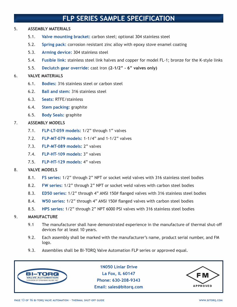
5. ASSEMBLY MATERIALS
5.1. Valve mounting bracket: carbon steel; optional 304 stainless steel
5.2. Spring pack: corrosion resistant zinc alloy with epoxy stove enamel coating
5.3. Arming device: 304 stainless steel
5.4. Fusible link: stainless steel link halves and copper for model FL-1; bronze for the K-style links
5.5. Declutch gear override: cast iron (2-1/2” - 6” valves only)
6. VALVE MATERIALS
6.1. Bodies: 316 stainless steel or carbon steel
6.2. Ball and stem: 316 stainless steel
6.3. Seats: RTFE/stainless
6.4. Stem packing: graphite
6.5. Body Seals: graphite
7. ASSEMBLY MODELS
7.1. FLP-LT-059 models: 1/2” through 1” valves
7.2. FLP-MT-079 models: 1-1/4” and 1-1/2” valves
7.3. FLP-MT-089 models: 2” valves
7.4. FLP-HT-109 models: 3” valves
7.5. FLP-HT-129 models: 4” valves
8. VALVE MODELS
8.1. FS series: 1/2” through 2” NPT or socket weld valves with 316 stainless steel bodies
8.2. FW series: 1/2” through 2” NPT or socket weld valves with carbon steel bodies
8.3. ED50 series: 1/2” through 4” ANSI 150# flanged valves with 316 stainless steel bodies
8.4. W50 series: 1/2” through 4” ANSI 150# flanged valves with carbon steel bodies
8.5. HPS series: 1/2” through 2” NPT 6000 PSI valves with 316 stainless steel bodies
9. MANUFACTURE
9.1 The manufacturer shall have demonstrated experience in the manufacture of thermal shut-off devices for at least 10 years.
9.2. Each assembly shall be marked with the manufacturer’s name, product serial number, and FM logo.
9.3. Assemblies shall be BI-TORQ Valve Automation FLP series or approved equal.
FLP SERIES SAMPLE SPECIFICATION
1N050 Linlar Drive
La Fox, IL 60147
Phone: 630-208-9343
Email: [email protected]

page 14 of 16 bi-torq valve automation - thermal shut-off guide www.bitorq.com
• Factory Mutual approved; UL and C-UL Listed• Fusible Link Halves: stainless steel• Fusible Assembly: solder, copper, stainless steel
FL-1: LT, MT AND HT-109 MODELS
• UL listed• Corrosion resistant bronze construction
K®: HT-129 THROUGH BT-189 MODELS
LINK PART
NUMBER
LINK YIELD TEMPERATURE
MAXIMUM AMBIENT
TEMPERATURE
FL-1-165 165°F/74°C 135°F/57°C
FL-1-212 212°F/100°C 185°F/82°C
FL-1-286 286°F/138°C 253°F/123°C
FL-1-360 360°F/182°C 330°F/166°C
LINK PART
NUMBER
LINK YIELD TEMPERATURE
MAXIMUM AMBIENT
TEMPERATURE
314165 165°F/74°C 135°F/57°C
314212 212°F/100°C 185°F/82°C
314280 286°F/138°C 253°F/123°C
314360 360°F/182°C 330°F/166°C
NOTE: Model FL-1 Fusible Links are not rated for use in corrosive atmospheres.
All BI-TORQ Thermal Shut-off Valves come with different link temperature options to fit your application. These link temperature are used on three different link types depending on the series and model. Determining link temperatures on individual assemblies is typically derived from the ambient temperature of the area, the flash point of the flammable media, and other factors. A 165°F or 212°F link are the most popular choices.
BI-TORQ Valve Automation and our soldered fusible link manufacturers suggest the annual replacement of fusible links as part of scheduled plant maintenance
LINK INFORMATION
LINK PART
NUMBER
LINK YIELD TEMPERATURE
MINIMUM
TRIP CURRENT
121165 165°F/74°C.2 amps
(50 millisecond min)
121212 212°F/100°C.2 amps
(50 millisecond min)
ETL: LT, MT, HT AND BT-149X MODELS
FOR FLP/FLP SERIES
FOR TES SERIES
• Part No. 121165 UL listed only• Indoor use only• Can be used on customer-specified valves• Trips via heat or low voltage 6-30 VAC-DC signal• Separates in 6-10 seconds
NOTE: ETL links are used only on non-FM approved assemblies and are not interchangable with the FLP/FL series links.
TES-LT series with a BI-TORQ
FW series Fire Safe BV

ACCESSORIES AND CUSTOMIZATIONS
Our design incorporates one or two proximity switches as an integral part of the assembly, allowing a remote operator to continuously record the open or closed position of the valve. This is especially crucial in fire safe applications where valves need to be monitored as part of a process system. We can also provide a dome indicator for easy field identification.
(NOTE: Not available on all units.)
INDICATION: REMOTE AND VISUAL
ENVIRONMENTAL PACKAGESNot every application is the same and BI-TORQ understands that. We can offer a number of different solutions to make our product fit the needs of your environment.
• Marine environment packages• Anti-vibration packages• Stainless steel components or special painting• Low temperature spring packs
CUSTOMIZATIONS: QUICK CHANGE LINKS & PIE COUPLER
Our HT and BT series use a number of links hold the spring pack tension. To help reduce link change out times, we can offer quick change packets where the links are all held together as a unit for easy change out. All models BT-149 and above come standard with this feature. Our series HT-109, HT-129, and BT-149X can have this feature added. It does negate the FM approval on these models. It is being submitted on for our new round of approvals.
Our latest innovation on our FLP/FL and TES series is a direct connect coupler. The new design allows for positive valve position feedback when using proximity switches. It also allows for an easy drop on connection that doesn’t rely on existing valve handles or stops on the customer supplied valves in our FL series. It also lets us use the same spring pack for fail open or fail close units, reducing lead times.
QUICK CHANGE LINKS
THE FOLLOWING CUSTOMIZATIONS ARE USED ON NON-FM APPROVED SERIES, BUT CAN BE ADAPTED TO OTHER SERIES IF FM APPROVAL IS NOT REQUIRED.
PIE DESIGN COUPLERS

IT WAS NEVER A FAIR FIGHT
BI-TORQ Valve Automation630-208-9343 • [email protected] •www.bitorq.com
FIRE SAFE VALVE SOLUTIONSFOR ALL INDUSTRIES