a tutorial on infrared optical materials m.r. burgener · invar 36, or super invar. this may lead...
TRANSCRIPT

Page 1 of 16
A Tutorial on Infrared Optical Materials
M.R. Burgener
7 November 2016
Introduction Depending on the literature there are different definitions of the imaging bands within the electromagnetic spectrum. For the purpose of this paper the definitions are going to be as follows; Visible (0.4 – 0.7µm), Near Infrared (NIR 0.1 – 1.0µm), Short Wave Infrared (SWIR 1.0 – 3.0µm), Mid Wave Infrared (MWIR 3.0 – 5.0µm), and Long Wave Infrared (LWIR 7.0 – 14.0µm). While the NIR and SWIR bands will be discussed this paper will focus on the MWIR and LWIR imaging bands. This paper will discuss the uses and pros and cons to the major MWIR and LWIR optical material including; Silicon, Zinc Sulfide (ZnS), Zinc Selenide (ZnSe), Germanium (Ge), Magnesium Fluoride (MgF2), Sapphire (Al2O3), Diamond (C), Aluminum Oxynitride (ALON), Spinel, Fused Silica, Calcium Fluoride (CaF2), Barium Fluoride (BaF2), Sodium Chloride (NaCl), Potassium Bromide (KBr) Mechanical Considerations For imaging systems especially those used outside the lab are going to have to be concerned with temperature changes. Equations 1, 2 and 3 define the mechanical considerations for imaging systems.
∆𝑓 = 𝛽 ∗ 𝑓 ∗ Δ𝑇 (1)
𝛽 = 𝛼 −1
𝑛−1∗𝑑𝑛
𝑑𝑇 (2)
∆𝐿 = 𝛼 ∗ Δ𝑇 (3) To maintain focus care will have to be taken to athermalize the system or into designing the focus compensation mechanism and code. Silicon (Si) As can be seen in Figures 1 and 2 Silicon is primarily used for the imaging the MWIR. There is not much response in the LWIR and usually only coated to support MWIR imaging. Silicon as both a low Thermal Expansion Coefficient (α) and Temperature Coefficient of the Refractive Index (dn/dT) (Table 1 and 2), which will make the change in focal length as a function of temperature low as can be seen in Equation 1 and 2. This means that any mechanical mounting or spacing fixtures will require a material with a similarly low α as to satisfy Equation 3. This could include Graphite Epoxy (CFRP),

Page 2 of 16
Invar 36, or Super Invar. This may lead to increased mechanical cost, as Silicon material is of moderate expense. It is cheaper that most materials that are suitable for outdoor use, but more expensive than some of the lab grade materials. It is a very good choice of material for MWIR imaging in an environment that requires a higher level of durability.
Figure 1 – Uncoated Silicon (Si) Transmission
Figure 2 – MWIR Anti-Reflection Coated Silicon (Si) Transmission

Page 3 of 16
Table 1 – Silicon (Si) Properties Part 1
Young’s Modulus (E)
(x1010Pa)
Density (ρ)
(g/cm3)
Thermal Expansion Coefficient (α)
(x10-6/°C)
Thermal Conductivity (λ)
(W/mK)
13.1 2.329 2.7 – 3.1 137
Table 2 – Silicon (Si) Properties Part 2
Refractive Index
Temperature Coefficient of the Refractive Index
Wavelength (µm)
N Wavelength
(µm) dn/dT
(x10-6/°C)
2.7 3.436
1.3 3.8 3.427
5.3 3.422
10.6 3.148
Zinc Sulfide (ZnS) aka Cleartran As can be seen in Figures 3 Zinc Sulfide can be used in a variety of imaging applications. Once coated with anti-reflection coating Zinc Sulfide can be used in the SWIR, MWIR, and/or LWIR. In many cases Zinc Sulfide is used as a window material when using a common aperture for imaging and laser applications. Once applied to Equations 1 and 2 there will be a negative change in the focal length of a lens which will add to the difficulty of pairing with mechanical material. While Zinc Sulfide has a great range in transmission leading to more flexible applications it is a soft material. It is harder than other material such as Zinc Selenide, but it is soft compared to other materials. Zinc Sulfide does suffer from temperature dependent refractive index, which will also play a part in Equations 1 and 2. This means that durability will be an issue if used in a harsher environment. It is an expensive material. Coupled with the cost and durability issues it is best to limit the use of this material to only those applications requiring common aperture multiband imaging and laser usage.

Page 4 of 16
Figure 3 – Uncoated Zinc Sulfide (ZnS) (Cleartran) Transmission
Table 3 – Zinc Sulfide (ZnS) Properties Part 1
Young’s Modulus (E)
(x1010Pa)
Density (ρ)
(g/cm3)
Thermal Expansion Coefficient (α)
(x10-6/°C)
Thermal Conductivity (λ)
(W/mK)
7.45 4.08 4.6 27.2
Table 4 – Zinc Sulfide (ZnS) Properties Part 2
Refractive Index
Temperature Coefficient of the Refractive Index
Wavelength (µm)
n Wavelength
(µm) dn/dT
(x10-6/°C)
0.6 2.36 0.63 63.5
3.0 2.257 1.15 49.8
5.0 2.246 10.6 46.3
10.6 2.192
Zinc Selenide (ZnSe) Zinc Selenide is very similar to Zinc Sulfide. As can be seen in Figure 4 Zinc Selenide is a broadband material supporting imaging. Due to the fact that Zinc Selenide is only about half as hard as Zinc Sulfide and low transmission when uncoated it is usually coated to support MWIR and LWIR imaging. It is an expensive material. Coupled with the cost and durability issues it is best to limit the used internal to a system using Zinc Sulfide as the external material to only those applications requiring common aperture multiband imaging and laser usage, or CO2 laser applications due to low absorption.

Page 5 of 16
Figure 4 – Uncoated Zinc Selenide (ZnSe) Transmission
Figure 5 – 3-12µm Anti-Reflection Coated Zinc Selenide (ZnSe) Transmission
Table 5 – Zinc Selenide (ZnSe) Properties Part 1
Young’s Modulus (E)
(x1010Pa)
Density (ρ)
(g/cm3)
Thermal Expansion Coefficient (α)
(x10-6/°C)
Thermal Conductivity (λ)
(W/mK)
7.03 5.27 7.1 18.0
Page 6 of 16
Table 6 – Zinc Selenide (ZnSe) Properties Part 2 Refractive
Index Temperature Coefficient of
the Refractive Index
Wavelength (µm)
n Wavelength
(µm) dn/dT
(x10-6/°C)
0.6 2.61 0.63 91.1
3.0 2.438 1.15 59.7
5.0 2.429 10.6 52.0
10.6 2.403
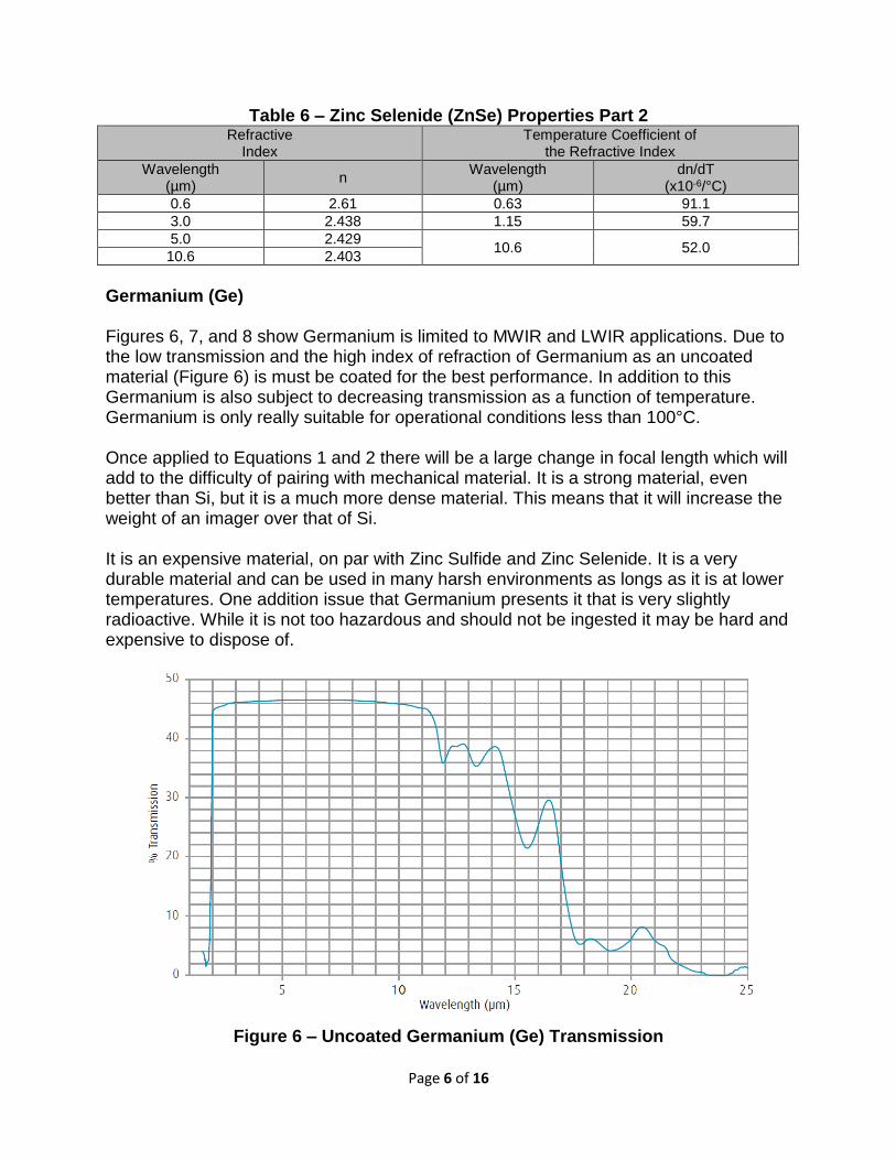
Germanium (Ge) Figures 6, 7, and 8 show Germanium is limited to MWIR and LWIR applications. Due to the low transmission and the high index of refraction of Germanium as an uncoated material (Figure 6) is must be coated for the best performance. In addition to this Germanium is also subject to decreasing transmission as a function of temperature. Germanium is only really suitable for operational conditions less than 100°C. Once applied to Equations 1 and 2 there will be a large change in focal length which will add to the difficulty of pairing with mechanical material. It is a strong material, even better than Si, but it is a much more dense material. This means that it will increase the weight of an imager over that of Si. It is an expensive material, on par with Zinc Sulfide and Zinc Selenide. It is a very durable material and can be used in many harsh environments as longs as it is at lower temperatures. One addition issue that Germanium presents it that is very slightly radioactive. While it is not too hazardous and should not be ingested it may be hard and expensive to dispose of.
Figure 6 – Uncoated Germanium (Ge) Transmission

Page 7 of 16
Figure 7 – 3-12µm Anti-Reflection Coated Germanium (Ge) Transmission
Figure 8 – LWIR Anti-Reflection Coated Germanium (Ge) Transmission
Table 7 – Germanium (Ge) Properties Part 1
Young’s Modulus (E)
(x1010Pa)
Density (ρ)
(g/cm3)
Thermal Expansion Coefficient (α)
(x10-6/°C)
Thermal Conductivity (λ)
(W/mK)
10.37 5.323 6.0 58.61
Table 8 – Germanium (Ge) Properties Part 2
Refractive Index
Temperature Coefficient of the Refractive Index
Wavelength (µm)
n Wavelength
(µm) dn/dT
(x10-6/°C)
2.7 4.055
424 3.8 4.026
5.3 4.015
10.6 4.00

Page 8 of 16
Magnesium Fluoride (MgF2) Magnesium Fluoride has excellent transmission in most wavebands, LWIR being the exception. Two of the most typical applications for Magnesium Fluoride, first is as an anti-reflection coating, second being when the use of an anti-reflective coating is undesirable or unwanted. As can be seen in Table 10 Magnesium Fluoride has a very low index of refraction. Magnesium Fluoride does suffer from high birefringence. Magnesium Fluoride is a durable material. It is resistant to chemical etching, shock (thermal and mechanical), and laser damage, which is another reason it is used as a coating material. Magnesium Fluoride does not cost as much as other materials when constructed in smaller sizes, but as the size of the optic increase it becomes similar in cost to Zinc Sulfide and Zinc Selenide.
Figure 9 – Uncoated Magnesium Fluoride (MgF2) Transmission
Page 9 of 16
Table 9 – Magnesium Fluoride (MgF2) Properties Part 1 Young’s Modulus
(E) (x1010Pa)
Density (ρ)
(g/cm3)
Thermal Expansion Coefficient (α)
(x10-6/°C)
Thermal Conductivity (λ)
(W/mK)
16.9 3.18 14.0(∥), 8.9(⊥) 11.6
Table 10 – Magnesium Fluoride (MgF2) Properties Part 2
Refractive Index
Temperature Coefficient of the Refractive Index
Wavelength (µm)
n Wavelength
(µm) dn/dT
(x10-6/°C)
0.46 1.384 1.15 0.88
3.8 1.356 3.39 1.19
5.3 1.333
Sapphire (Al2O3) As can be seen in Figures 10 Sapphire can be used in a variety of imaging applications. It has decent transmission in the SWIR and MWIR wavebands. It also has good transmission down through the visible band. Since Sapphire is a crystal it does suffer from birefringence. Once applied to Equations 1 and 2 it comes out very near to Aluminum as far as the change in focal length compared to the change in length of pure Aluminum. One of the biggest benefits of Sapphire is that it is very strong and durable. Thus for many applications it can be made thinner than other materials to meet stress and strain requirements. Sapphire is one of the more expensive materials for two reasons. The first is that since it is a crystal it is grown to size when ordered. The second is that since it is very hard it is hard to polish. Sapphire is the second hardest crystal behind diamond. Since diamond is what is used to polish optical material it will take a greater amount of time to polish Sapphire to the required specifications. Sapphire is usually used in high heat or pressure applications.

Page 10 of 16
Figure 10 – Uncoated Sapphire (Al2O3) Transmission
Table 11 – Sapphire (Al2O3) Properties Part 1
Young’s Modulus (E)
(x1010Pa)
Density (ρ)
(g/cm3)
Thermal Expansion Coefficient (α)
(x10-6/°C)
Thermal Conductivity (λ)
(W/mK)
40.0 3.97 5.6(∥), 5.0(⊥) 46
Table 12 – Sapphire (Al2O3) Properties Part 2
Refractive Index
Temperature Coefficient of the Refractive Index
Wavelength (µm)
n Wavelength
(µm) dn/dT
(x10-6/°C)
3.8 1.684 13.7
5.8 1.586
Diamond (C) Diamond is one of those materials that is very rare to use. Is it very expensive, greater than that of Sapphire. This is due to the polishing process. Since diamond is usually used for polishing this will be an issue. Diamond is usually built up through Chemical Vapor Desposition (CVD) and then polished. As can be seen in Figure 11 Diamond has excellent transmission in all wavebands. Diamond also has a very high Thermal Conductivity, which allows for use in high temperature applications, such as high energy lasers. CVD Diamond is also biocompatible. It can be used for medical applications.

Page 11 of 16
Figure 11 – Uncoated Diamond (C) Transmission
Table 13 – Diamond (C) Properties Part 1
Young’s Modulus (E)
(x1010Pa)
Density (ρ)
(g/cm3)
Thermal Expansion Coefficient (α)
(x10-6/°C)
Thermal Conductivity (λ)
(W/mK)
114.3 3.51 0.8 >1,800
Table 14 – Diamond (C) Properties Part 2
Refractive Index
Temperature Coefficient of the Refractive Index
Wavelength (µm)
n Wavelength
(µm) dn/dT
(x10-6/°C)
2.5 2.382
9.6 5.0 2.381
10.6 2.381
Aluminum Oxynitride (ALON Al(64+x)/3O32-xNx) ALON is a transparent ceramic material. ALON can be used from the Ultraviolet to the MWIR wavebands. ALON is very comparable in strength to Sapphire, but suffers from a greater falloff in transmission at the higher end of the MWIR band than Sapphire or Spinel. Since ALON is a ceramic it is produced by either cold isostatic pressing, slip-casting, or injection molding. These are standard processing for ceramic materials. This means that ALON should be less expensive than Sapphire and that more complex shapes can be made.

Page 12 of 16
Despite the fact that ALON is comparable in strength to Sapphire the manufacturer, Surmet, states that it can be ground and polished at a much more reasonable cost due to its cubic structure. ALON is usually used as a lower cost alternative to Sapphire for imaging applications. According to Surmet another large potential application is transparent ballistic armor. One of the other down side to ALON is that, currently, there is only one manufacture, Surmet.
Figure 12 – Uncoated Aluminum Oxynitride (ALON) Transmission
Table 15 – ALON Properties Part 1
Young’s Modulus (E)
(x1010Pa)
Density (ρ)
(g/cm3)
Thermal Expansion Coefficient (α)
(x10-6/°C)
Thermal Conductivity (λ)
(W/mK)
32.2 3.71 5.8 12.6
Table 16 – ALON Properties Part 2
Refractive Index
Temperature Coefficient of the Refractive Index
Wavelength (µm)
n Wavelength
(µm) dn/dT
(x10-6/°C)
0.6 1.793 0.633 14.6
4.0 1.66
Spinel (MgAl2O4) Spinel is much like ALON in that it is a transparent ceramic material. Just like ALON Spinel can be used from the Ultraviolet to the MWIR wavebands. Spinel is very comparable in strength to Sapphire but is lower than either Sapphire or ALON. Of the three Spinel offers the best falloff in transmission at the higher end of the MWIR band

Page 13 of 16
than Sapphire or Spinel. Since Spinel is a ceramic it is produced by either cold isostatic pressing, slip-casting, or injection molding. These are standard processing for ceramic materials. This means that Spinel should be less expensive than Sapphire and that more complex shapes can be made. Despite the fact that Spinel is comparable in strength to Sapphire the manufacturer, Surmet, states that it can be ground and polished at a much more reasonable cost due to its cubic structure. Spinel is usually used as a lower cost alternative to Sapphire for imaging applications. One of the other down side to Spinel is that, currently, there is only one manufacture, Surmet.
Figure 13 – Uncoated Spinel Transmission
Table 17 – Spinel Properties Part 1
Young’s Modulus (E)
(x1010Pa)
Density (ρ)
(g/cm3)
Thermal Expansion Coefficient (α)
(x10-6/°C)
Thermal Conductivity (λ)
(W/mK)
27.6 3.58 6.97 25
Table 18 – Spinel Properties Part 2
Refractive Index
Temperature Coefficient of the Refractive Index
Wavelength (µm)
n Wavelength
(µm) dn/dT
(x10-6/°C)
0.6 1.7155
3 – 5 3 3 1.6677
5 1.598
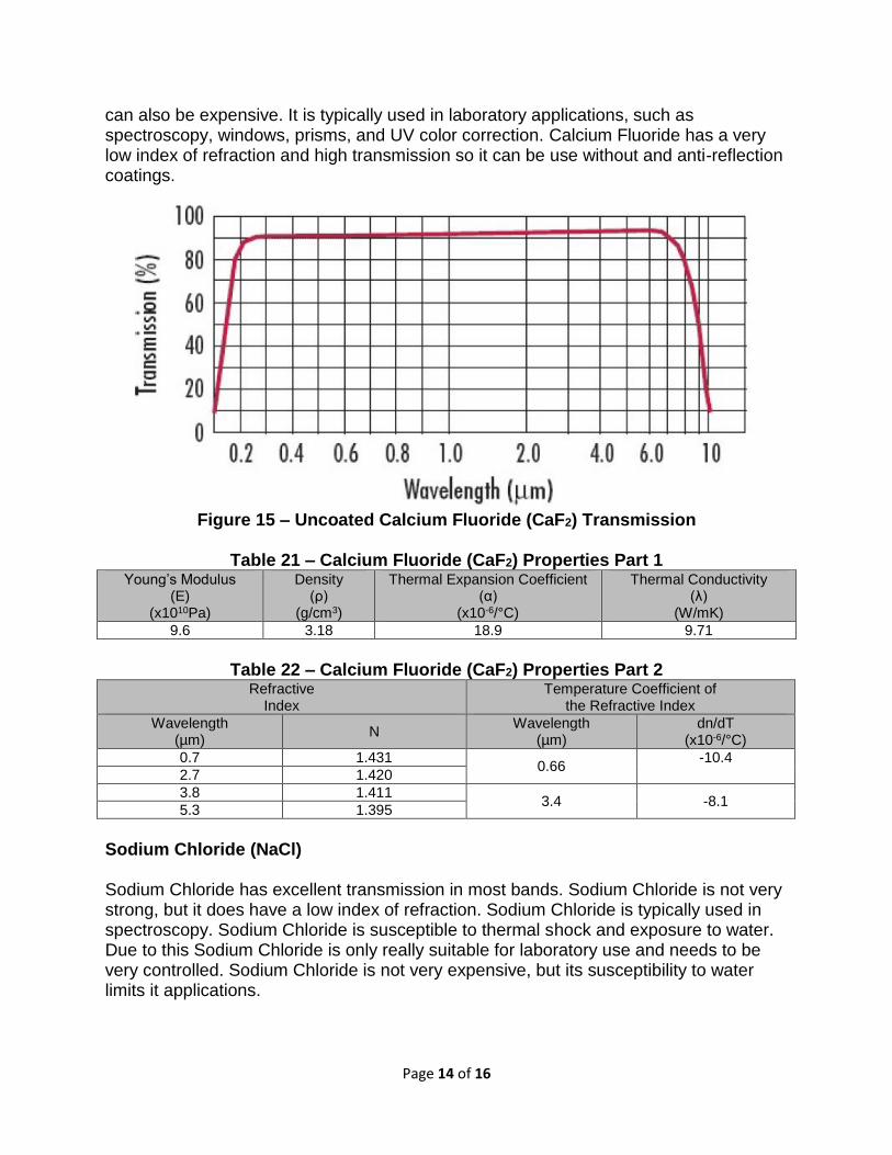
Calcium Fluoride (CaF2) Calcium Fluoride has very good transmission over a very wide range. It can support applications in the SWIR and MWIR in addition to visible, NIR, and UV bands. From Table 21 it can be seen that Calcium Fluoride is not a very strong or durable material. It
Page 14 of 16
can also be expensive. It is typically used in laboratory applications, such as spectroscopy, windows, prisms, and UV color correction. Calcium Fluoride has a very low index of refraction and high transmission so it can be use without and anti-reflection coatings.
Figure 15 – Uncoated Calcium Fluoride (CaF2) Transmission
Table 21 – Calcium Fluoride (CaF2) Properties Part 1
Young’s Modulus (E)
(x1010Pa)
Density (ρ)
(g/cm3)
Thermal Expansion Coefficient (α)
(x10-6/°C)
Thermal Conductivity (λ)
(W/mK)
9.6 3.18 18.9 9.71
Table 22 – Calcium Fluoride (CaF2) Properties Part 2
Refractive Index
Temperature Coefficient of the Refractive Index
Wavelength (µm)
N Wavelength
(µm) dn/dT
(x10-6/°C)
0.7 1.431 0.66
-10.4
2.7 1.420
3.8 1.411 3.4 -8.1
5.3 1.395
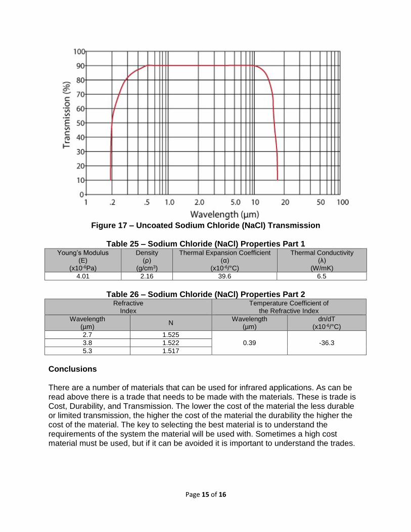
Sodium Chloride (NaCl) Sodium Chloride has excellent transmission in most bands. Sodium Chloride is not very strong, but it does have a low index of refraction. Sodium Chloride is typically used in spectroscopy. Sodium Chloride is susceptible to thermal shock and exposure to water. Due to this Sodium Chloride is only really suitable for laboratory use and needs to be very controlled. Sodium Chloride is not very expensive, but its susceptibility to water limits it applications.
Page 15 of 16
Figure 17 – Uncoated Sodium Chloride (NaCl) Transmission
Table 25 – Sodium Chloride (NaCl) Properties Part 1
Young’s Modulus (E)
(x10-6Pa)
Density (ρ)
(g/cm3)
Thermal Expansion Coefficient (α)
(x10-6/°C)
Thermal Conductivity (λ)
(W/mK)
4.01 2.16 39.6 6.5
Table 26 – Sodium Chloride (NaCl) Properties Part 2
Refractive Index
Temperature Coefficient of the Refractive Index
Wavelength (µm)
N Wavelength
(µm) dn/dT
(x10-6/°C)
2.7 1.525
0.39 -36.3 3.8 1.522
5.3 1.517
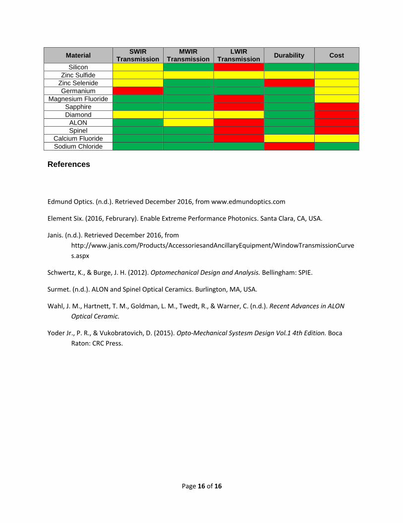
Conclusions There are a number of materials that can be used for infrared applications. As can be read above there is a trade that needs to be made with the materials. These is trade is Cost, Durability, and Transmission. The lower the cost of the material the less durable or limited transmission, the higher the cost of the material the durability the higher the cost of the material. The key to selecting the best material is to understand the requirements of the system the material will be used with. Sometimes a high cost material must be used, but if it can be avoided it is important to understand the trades.
Page 16 of 16
Material SWIR
Transmission MWIR
Transmission LWIR
Transmission Durability Cost
Silicon
Zinc Sulfide
Zinc Selenide
Germanium
Magnesium Fluoride
Sapphire
Diamond
ALON
Spinel
Calcium Fluoride
Sodium Chloride
References
Edmund Optics. (n.d.). Retrieved December 2016, from www.edmundoptics.com
Element Six. (2016, Februrary). Enable Extreme Performance Photonics. Santa Clara, CA, USA.
Janis. (n.d.). Retrieved December 2016, from
http://www.janis.com/Products/AccessoriesandAncillaryEquipment/WindowTransmissionCurve
s.aspx
Schwertz, K., & Burge, J. H. (2012). Optomechanical Design and Analysis. Bellingham: SPIE.
Surmet. (n.d.). ALON and Spinel Optical Ceramics. Burlington, MA, USA.
Wahl, J. M., Hartnett, T. M., Goldman, L. M., Twedt, R., & Warner, C. (n.d.). Recent Advances in ALON
Optical Ceramic.
Yoder Jr., P. R., & Vukobratovich, D. (2015). Opto-Mechanical Systesm Design Vol.1 4th Edition. Boca
Raton: CRC Press.