a study on selection of photovoltaic solar panels
TRANSCRIPT
A study &SelectionOf Photovoltaic Solar Panels
A study &SelectionOf Photovoltaic Solar Panels
EnvironmentFirst Energy Services Pvt. Ltd.
Presentation by:Harish SharmaDirector-EFESPL

Photovoltaic (PV) Cell• A photovoltaic cell (PV
cell) is a specializedsemiconductor diode thatconverts visible light intodirect current (DC). SomePV cells can also convertinfrared (IR) or ultraviolet(UV) radiation into DCelectricity.
• A photovoltaic cell (PVcell) is a specializedsemiconductor diode thatconverts visible light intodirect current (DC). SomePV cells can also convertinfrared (IR) or ultraviolet(UV) radiation into DCelectricity.
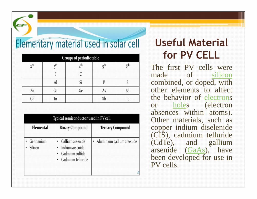
Useful Materialfor PV CELL
The first PV cells weremade of siliconcombined, or doped, withother elements to affectthe behavior of electronsor holes (electronabsences within atoms).Other materials, such ascopper indium diselenide(CIS), cadmium telluride(CdTe), and galliumarsenide (GaAs), havebeen developed for use inPV cells.
The first PV cells weremade of siliconcombined, or doped, withother elements to affectthe behavior of electronsor holes (electronabsences within atoms).Other materials, such ascopper indium diselenide(CIS), cadmium telluride(CdTe), and galliumarsenide (GaAs), havebeen developed for use inPV cells.
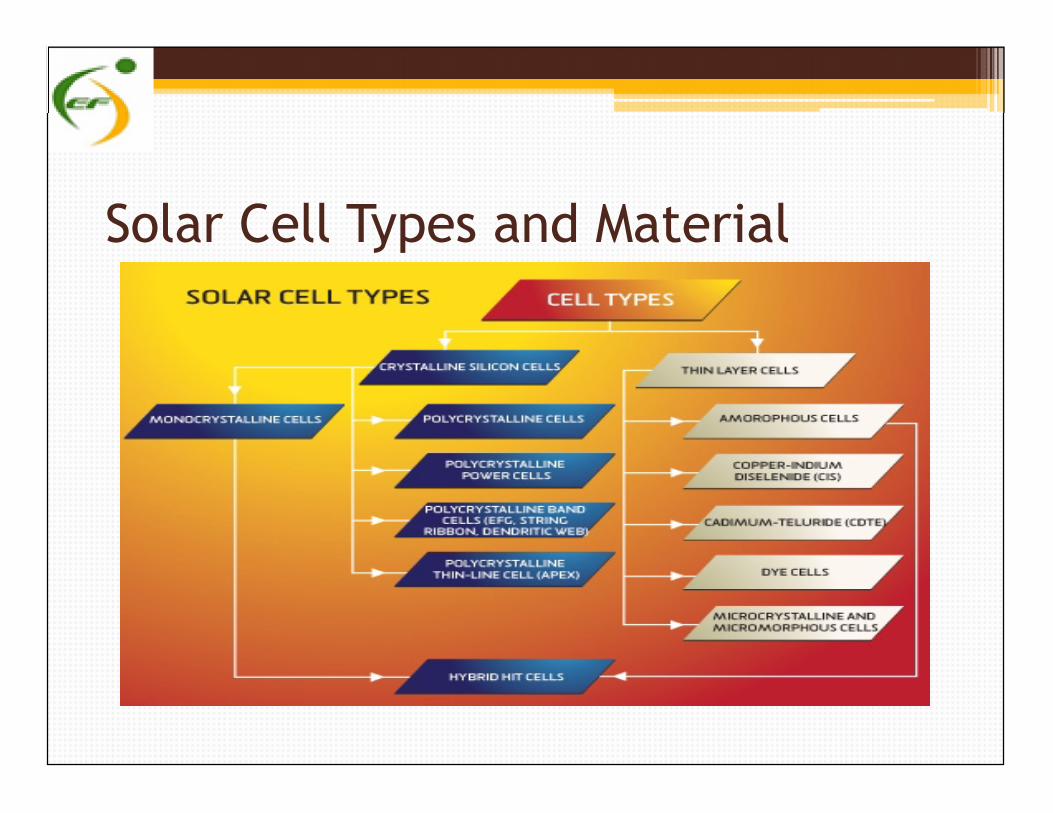
Solar Cell Types and Material

Form
atio
n O
f P-
N J
unct
ion
There are twobasic types ofsemiconductormaterial, calledpositive (or P type)and negative (or Ntype). In a PV cell,flat pieces of thesematerials areplaced together,and the physicalboundary betweenthem is called theP-N junction.
Form
atio
n O
f P-
N J
unct
ion
There are twobasic types ofsemiconductormaterial, calledpositive (or P type)and negative (or Ntype). In a PV cell,flat pieces of thesematerials areplaced together,and the physicalboundary betweenthem is called theP-N junction.
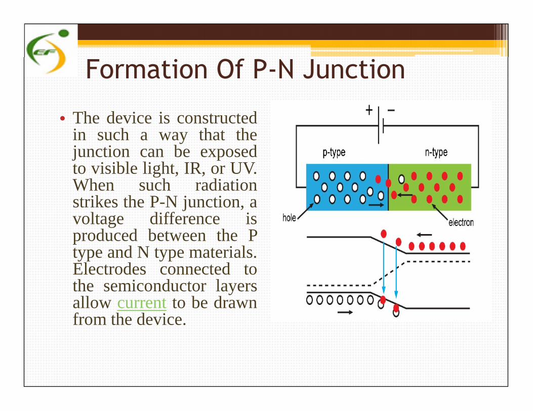
Formation Of P-N Junction
• The device is constructedin such a way that thejunction can be exposedto visible light, IR, or UV.When such radiationstrikes the P-N junction, avoltage difference isproduced between the Ptype and N type materials.Electrodes connected tothe semiconductor layersallow current to be drawnfrom the device.
• The device is constructedin such a way that thejunction can be exposedto visible light, IR, or UV.When such radiationstrikes the P-N junction, avoltage difference isproduced between the Ptype and N type materials.Electrodes connected tothe semiconductor layersallow current to be drawnfrom the device.
Photovoltaic
• Large sets of PV cells can be connected together to formsolar modules, arrays, or panels. The use of PV cells andbatteries for the generation of usable electrical energy isknown as photovoltaics. One of the major advantages ofphotovoltaics is the fact that it is non-polluting, requiringonly real estate (and a reasonably sunny climate) in orderto function. Another advantage is the fact that solarenergy is unlimited. Once a photovoltaic system has beeninstalled, it can provide energy at essentially no cost foryears, and with minimal maintenance.
• Large sets of PV cells can be connected together to formsolar modules, arrays, or panels. The use of PV cells andbatteries for the generation of usable electrical energy isknown as photovoltaics. One of the major advantages ofphotovoltaics is the fact that it is non-polluting, requiringonly real estate (and a reasonably sunny climate) in orderto function. Another advantage is the fact that solarenergy is unlimited. Once a photovoltaic system has beeninstalled, it can provide energy at essentially no cost foryears, and with minimal maintenance.
What is Solar Energy?
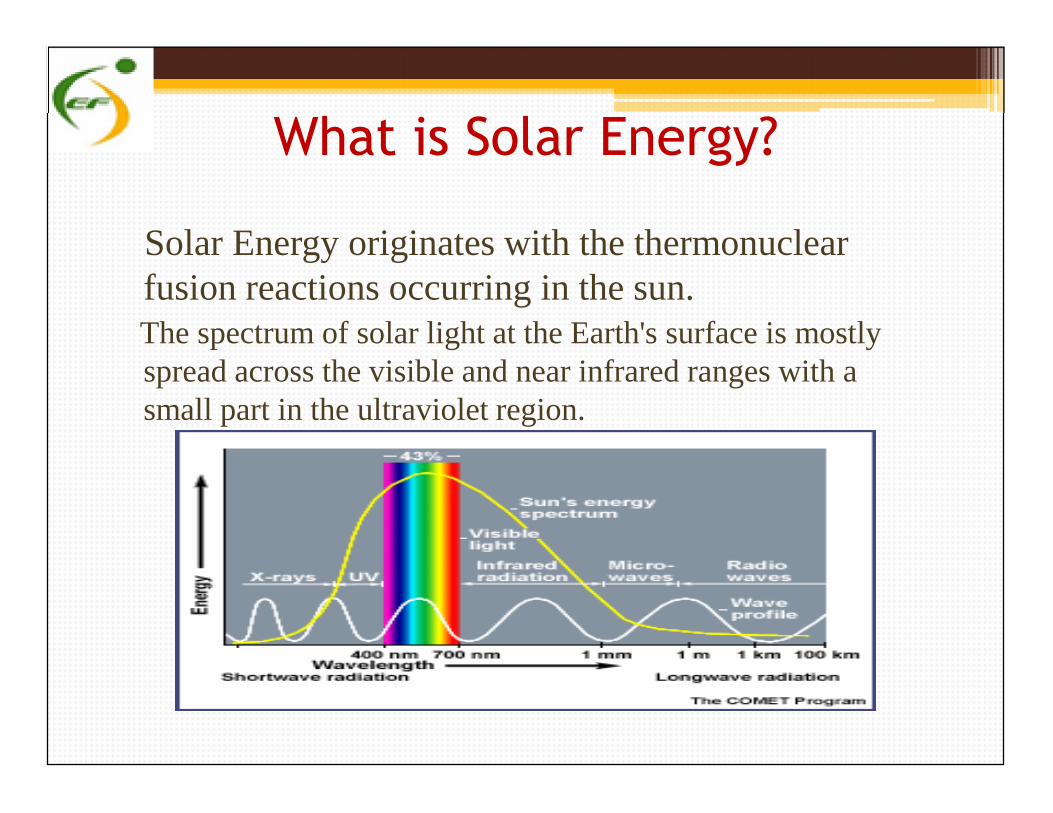
Solar Energy originates with the thermonuclearfusion reactions occurring in the sun.The spectrum of solar light at the Earth's surface is mostlyspread across the visible and near infrared ranges with asmall part in the ultraviolet region.
Solar Energy originates with the thermonuclearfusion reactions occurring in the sun.The spectrum of solar light at the Earth's surface is mostlyspread across the visible and near infrared ranges with asmall part in the ultraviolet region.

How much solar energy?
• About half the incoming solar energy reaches the Earth's surface.
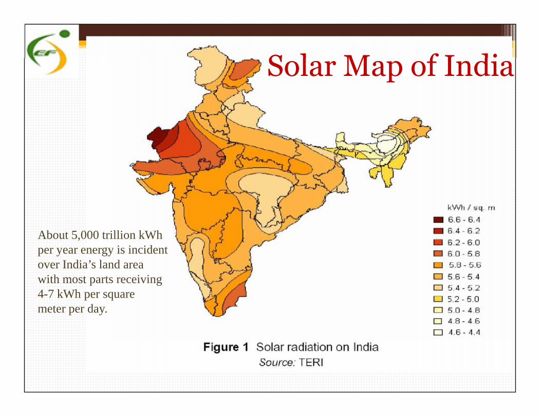
Solar Map of India
About 5,000 trillion kWhper year energy is incidentover India’s land areawith most parts receiving4-7 kWh per squaremeter per day.
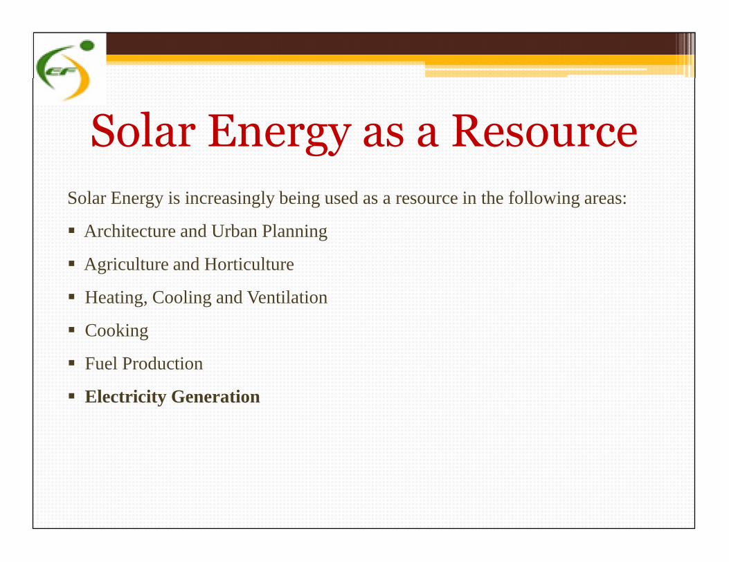
Solar Energy as a ResourceSolar Energy is increasingly being used as a resource in the following areas:
Architecture and Urban Planning
Agriculture and Horticulture
Heating, Cooling and Ventilation
Cooking
Fuel Production
Electricity Generation
Solar Energy is increasingly being used as a resource in the following areas:
Architecture and Urban Planning
Agriculture and Horticulture
Heating, Cooling and Ventilation
Cooking
Fuel Production
Electricity Generation
Producing Electricity using Solar Energy
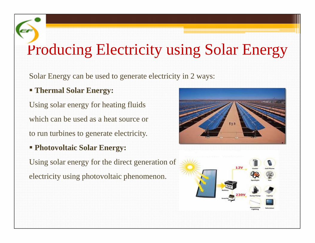
Solar Energy can be used to generate electricity in 2 ways:
Thermal Solar Energy:
Using solar energy for heating fluids
which can be used as a heat source or
to run turbines to generate electricity.
Photovoltaic Solar Energy:
Using solar energy for the direct generation of
electricity using photovoltaic phenomenon.
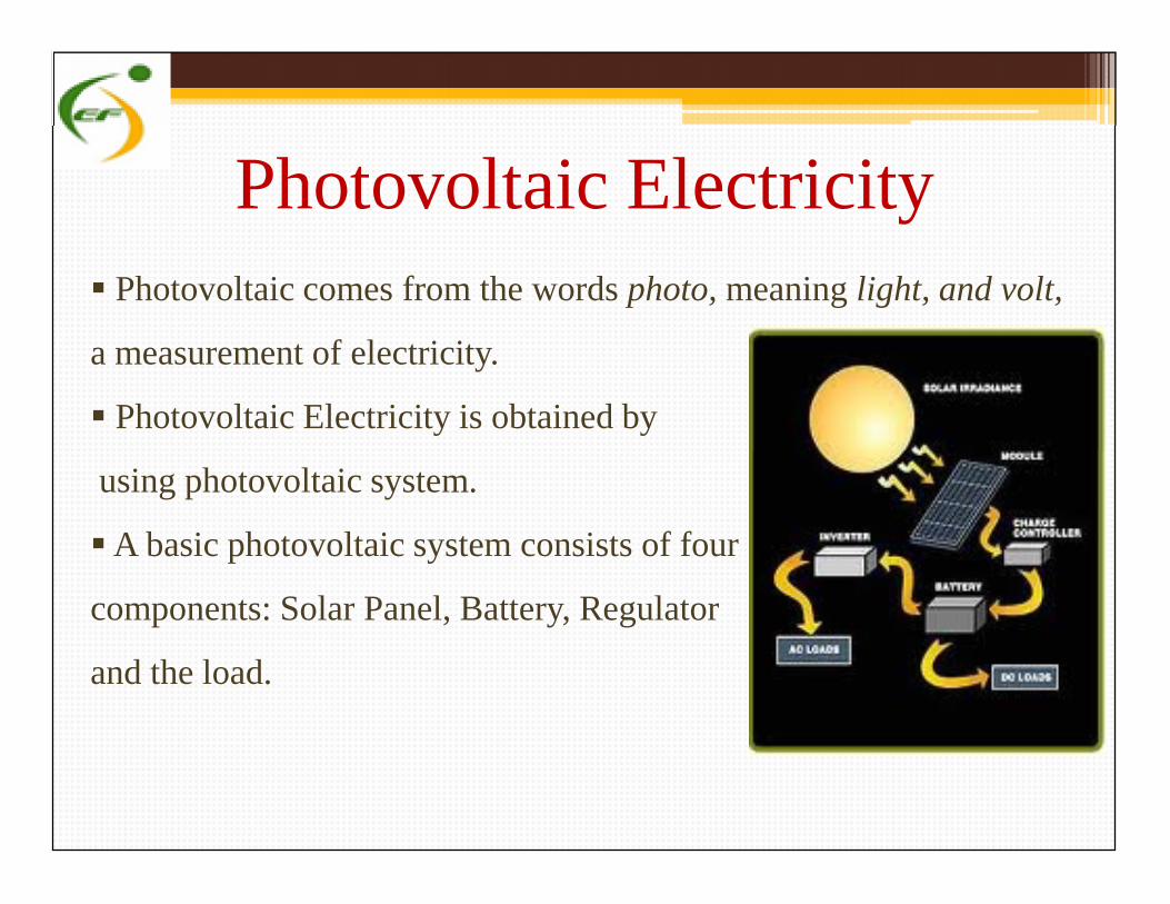
Photovoltaic Electricity Photovoltaic comes from the words photo, meaning light, and volt,
a measurement of electricity.
Photovoltaic Electricity is obtained by
using photovoltaic system.
A basic photovoltaic system consists of four
components: Solar Panel, Battery, Regulator
and the load.
Photovoltaic comes from the words photo, meaning light, and volt,
a measurement of electricity.
Photovoltaic Electricity is obtained by
using photovoltaic system.
A basic photovoltaic system consists of four
components: Solar Panel, Battery, Regulator
and the load.
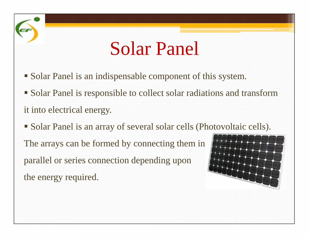
Solar Panel Solar Panel is an indispensable component of this system.
Solar Panel is responsible to collect solar radiations and transform
it into electrical energy.
Solar Panel is an array of several solar cells (Photovoltaic cells).
The arrays can be formed by connecting them in
parallel or series connection depending upon
the energy required.
Solar Panel is an indispensable component of this system.
Solar Panel is responsible to collect solar radiations and transform
it into electrical energy.
Solar Panel is an array of several solar cells (Photovoltaic cells).
The arrays can be formed by connecting them in
parallel or series connection depending upon
the energy required.

Panel Manufacturing Technologies
The most common solar technology is crystalline Si. Its two types
are: Mono- Si and Poly- Si.
Mono-Si: Crystal Lattice of entire
Sample is continuous.
Poly-Si: Composed of many crystallites
of varying size and orientation.
The most common solar technology is crystalline Si. Its two types
are: Mono- Si and Poly- Si.
Mono-Si: Crystal Lattice of entire
Sample is continuous.
Poly-Si: Composed of many crystallites
of varying size and orientation.
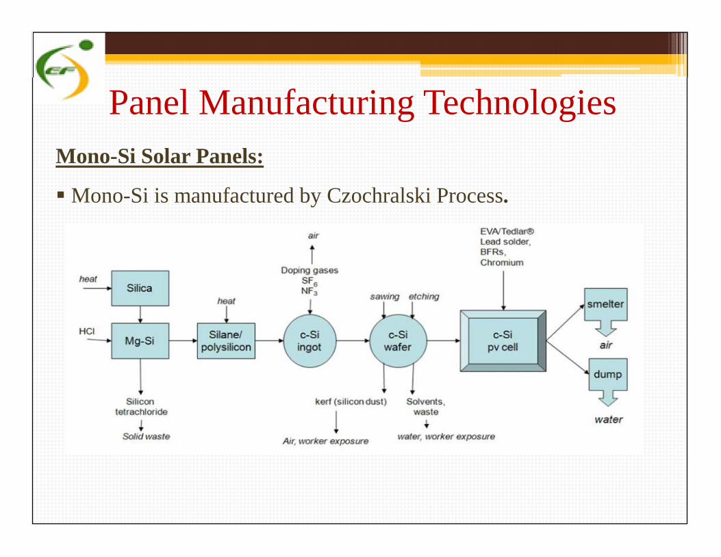
Panel Manufacturing TechnologiesMono-Si Solar Panels:
Mono-Si is manufactured by Czochralski Process.
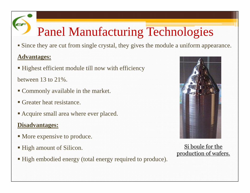
Since they are cut from single crystal, they gives the module a uniform appearance.
Advantages:
Highest efficient module till now with efficiency
between 13 to 21%.
Commonly available in the market.
Greater heat resistance.
Acquire small area where ever placed.
Disadvantages:
More expensive to produce.
High amount of Silicon.
High embodied energy (total energy required to produce).
Panel Manufacturing Technologies Since they are cut from single crystal, they gives the module a uniform appearance.
Advantages:
Highest efficient module till now with efficiency
between 13 to 21%.
Commonly available in the market.
Greater heat resistance.
Acquire small area where ever placed.
Disadvantages:
More expensive to produce.
High amount of Silicon.
High embodied energy (total energy required to produce).
Si boule for theproduction of wafers.
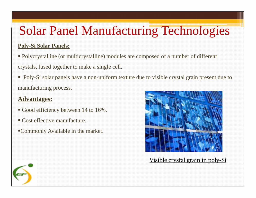
Poly-Si Solar Panels:
Polycrystalline (or multicrystalline) modules are composed of a number of different
crystals, fused together to make a single cell.
Poly-Si solar panels have a non-uniform texture due to visible crystal grain present due to
manufacturing process.
Advantages:
Good efficiency between 14 to 16%.
Cost effective manufacture.
Commonly Available in the market.
Solar Panel Manufacturing TechnologiesPoly-Si Solar Panels:
Polycrystalline (or multicrystalline) modules are composed of a number of different
crystals, fused together to make a single cell.
Poly-Si solar panels have a non-uniform texture due to visible crystal grain present due to
manufacturing process.
Advantages:
Good efficiency between 14 to 16%.
Cost effective manufacture.
Commonly Available in the market.
Visible crystal grain in poly-Si
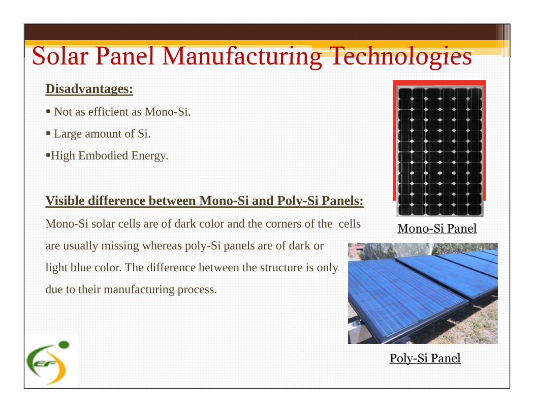
Disadvantages:
Not as efficient as Mono-Si.
Large amount of Si.
High Embodied Energy.
Visible difference between Mono-Si and Poly-Si Panels:
Mono-Si solar cells are of dark color and the corners of the cells
are usually missing whereas poly-Si panels are of dark or
light blue color. The difference between the structure is only
due to their manufacturing process.
Solar Panel Manufacturing TechnologiesDisadvantages:
Not as efficient as Mono-Si.
Large amount of Si.
High Embodied Energy.
Visible difference between Mono-Si and Poly-Si Panels:
Mono-Si solar cells are of dark color and the corners of the cells
are usually missing whereas poly-Si panels are of dark or
light blue color. The difference between the structure is only
due to their manufacturing process.
Mono-Si Panel
Poly-Si Panel
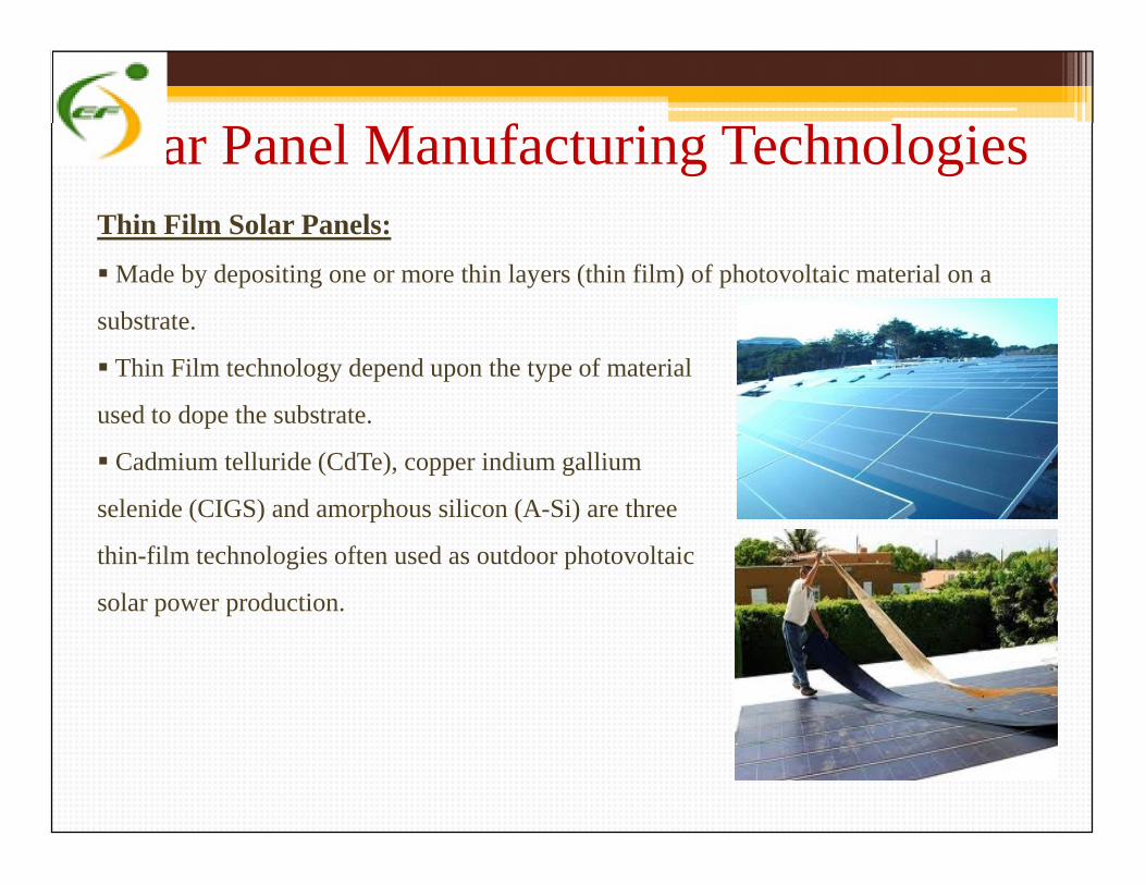
Solar Panel Manufacturing TechnologiesThin Film Solar Panels:
Made by depositing one or more thin layers (thin film) of photovoltaic material on a
substrate.
Thin Film technology depend upon the type of material
used to dope the substrate.
Cadmium telluride (CdTe), copper indium gallium
selenide (CIGS) and amorphous silicon (A-Si) are three
thin-film technologies often used as outdoor photovoltaic
solar power production.
Thin Film Solar Panels:
Made by depositing one or more thin layers (thin film) of photovoltaic material on a
substrate.
Thin Film technology depend upon the type of material
used to dope the substrate.
Cadmium telluride (CdTe), copper indium gallium
selenide (CIGS) and amorphous silicon (A-Si) are three
thin-film technologies often used as outdoor photovoltaic
solar power production.
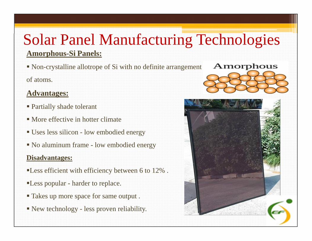
Amorphous-Si Panels:
Non-crystalline allotrope of Si with no definite arrangement
of atoms.
Advantages:
Partially shade tolerant
More effective in hotter climate
Uses less silicon - low embodied energy
No aluminum frame - low embodied energy
Disadvantages:
Less efficient with efficiency between 6 to 12% .
Less popular - harder to replace.
Takes up more space for same output .
New technology - less proven reliability.
Solar Panel Manufacturing TechnologiesAmorphous-Si Panels:
Non-crystalline allotrope of Si with no definite arrangement
of atoms.
Advantages:
Partially shade tolerant
More effective in hotter climate
Uses less silicon - low embodied energy
No aluminum frame - low embodied energy
Disadvantages:
Less efficient with efficiency between 6 to 12% .
Less popular - harder to replace.
Takes up more space for same output .
New technology - less proven reliability.
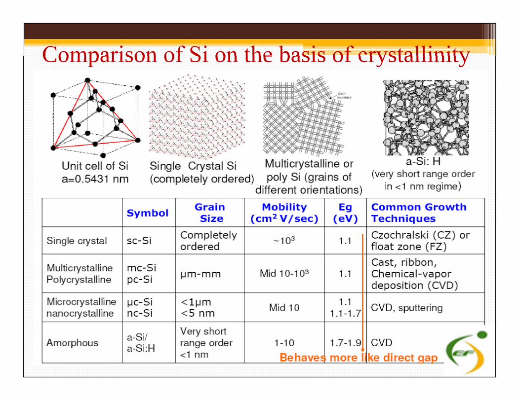
Comparison of Si on the basis of crystallinity
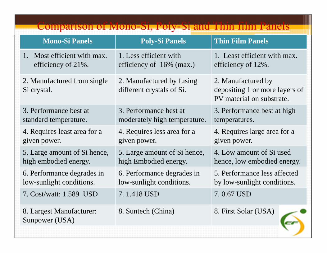
Comparison of Mono-Si, Poly-Si and Thin film PanelsMono-Si Panels Poly-Si Panels Thin Film Panels
1. Most efficient with max.efficiency of 21%.
1. Less efficient withefficiency of 16% (max.)
1. Least efficient with max.efficiency of 12%.
2. Manufactured from singleSi crystal.
2. Manufactured by fusingdifferent crystals of Si.
2. Manufactured bydepositing 1 or more layers ofPV material on substrate.
3. Performance best atstandard temperature.
3. Performance best atmoderately high temperature.
3. Performance best at hightemperatures.
4. Requires least area for agiven power.
4. Requires less area for agiven power.
4. Requires large area for agiven power.
4. Requires least area for agiven power.
4. Requires less area for agiven power.
4. Requires large area for agiven power.
5. Large amount of Si hence,high embodied energy.
5. Large amount of Si hence,high Embodied energy.
4. Low amount of Si usedhence, low embodied energy.
6. Performance degrades inlow-sunlight conditions.
6. Performance degrades inlow-sunlight conditions.
5. Performance less affectedby low-sunlight conditions.
7. Cost/watt: 1.589 USD 7. 1.418 USD 7. 0.67 USD
8. Largest Manufacturer:Sunpower (USA)
8. Suntech (China) 8. First Solar (USA)
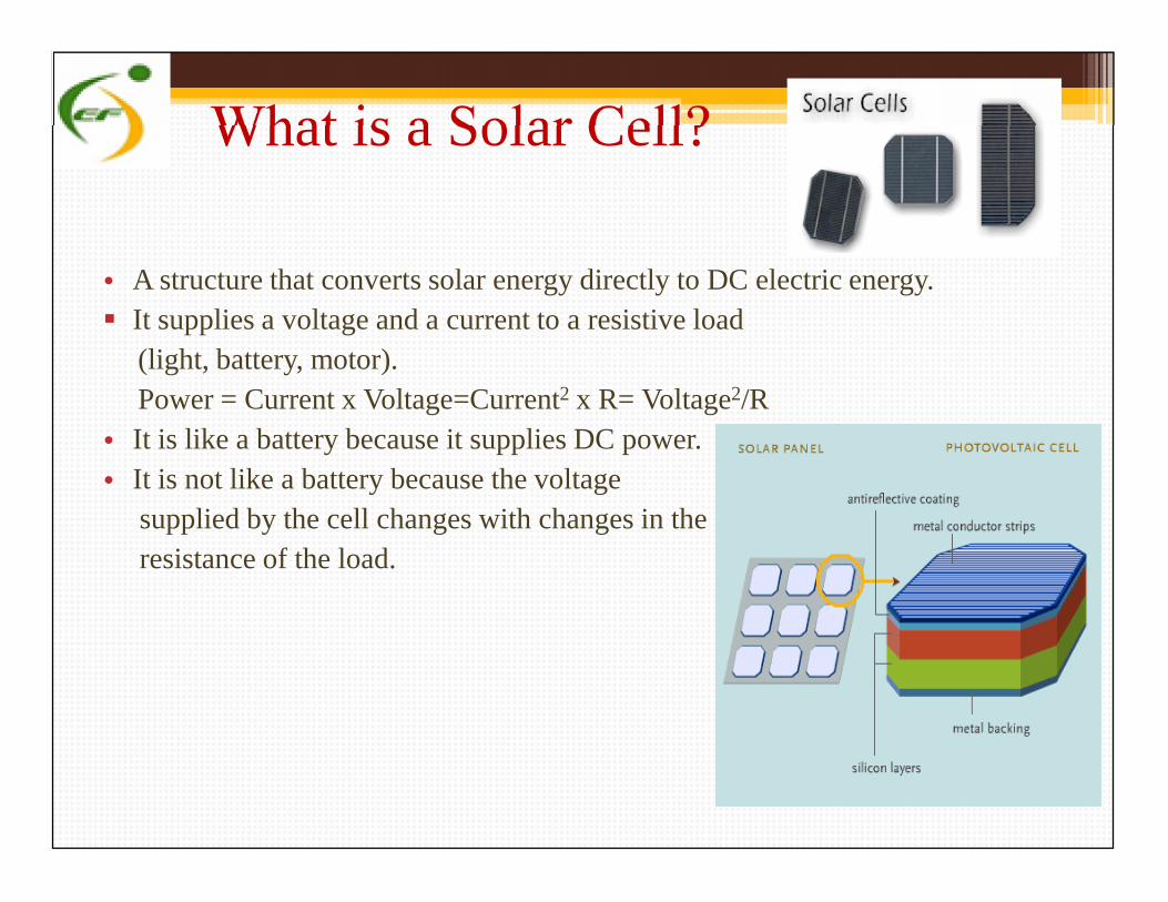
What is a Solar Cell?
• A structure that converts solar energy directly to DC electric energy. It supplies a voltage and a current to a resistive load
(light, battery, motor).Power = Current x Voltage=Current2 x R= Voltage2/R
• It is like a battery because it supplies DC power.• It is not like a battery because the voltage
supplied by the cell changes with changes in theresistance of the load.
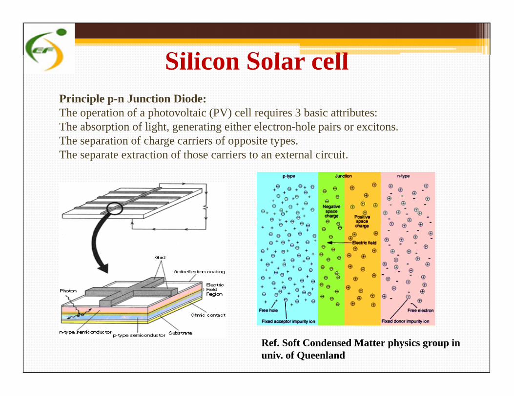
Principle p-n Junction Diode:The operation of a photovoltaic (PV) cell requires 3 basic attributes:The absorption of light, generating either electron-hole pairs or excitons.The separation of charge carriers of opposite types.The separate extraction of those carriers to an external circuit.
Silicon Solar cell
Ref. Soft Condensed Matter physics group inuniv. of Queenland

How a panel is created?
An individual PV cell typically produces 0.6 watts and arejoined in an array to produce the required power.
Panel wiring diagram connecting cells
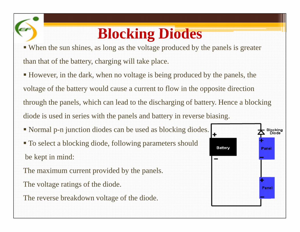
Blocking DiodesWhen the sun shines, as long as the voltage produced by the panels is greater
than that of the battery, charging will take place.
However, in the dark, when no voltage is being produced by the panels, the
voltage of the battery would cause a current to flow in the opposite direction
through the panels, which can lead to the discharging of battery. Hence a blocking
diode is used in series with the panels and battery in reverse biasing.
Normal p-n junction diodes can be used as blocking diodes.
To select a blocking diode, following parameters should
be kept in mind:
The maximum current provided by the panels.
The voltage ratings of the diode.
The reverse breakdown voltage of the diode.
When the sun shines, as long as the voltage produced by the panels is greater
than that of the battery, charging will take place.
However, in the dark, when no voltage is being produced by the panels, the
voltage of the battery would cause a current to flow in the opposite direction
through the panels, which can lead to the discharging of battery. Hence a blocking
diode is used in series with the panels and battery in reverse biasing.
Normal p-n junction diodes can be used as blocking diodes.
To select a blocking diode, following parameters should
be kept in mind:
The maximum current provided by the panels.
The voltage ratings of the diode.
The reverse breakdown voltage of the diode.
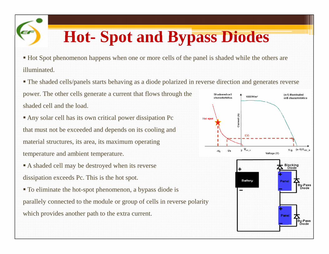
Hot- Spot and Bypass Diodes Hot Spot phenomenon happens when one or more cells of the panel is shaded while the others are
illuminated.
The shaded cells/panels starts behaving as a diode polarized in reverse direction and generates reverse
power. The other cells generate a current that flows through the
shaded cell and the load.
Any solar cell has its own critical power dissipation Pc
that must not be exceeded and depends on its cooling and
material structures, its area, its maximum operating
temperature and ambient temperature.
A shaded cell may be destroyed when its reverse
dissipation exceeds Pc. This is the hot spot.
To eliminate the hot-spot phenomenon, a bypass diode is
parallely connected to the module or group of cells in reverse polarity
which provides another path to the extra current.
Hot Spot phenomenon happens when one or more cells of the panel is shaded while the others are
illuminated.
The shaded cells/panels starts behaving as a diode polarized in reverse direction and generates reverse
power. The other cells generate a current that flows through the
shaded cell and the load.
Any solar cell has its own critical power dissipation Pc
that must not be exceeded and depends on its cooling and
material structures, its area, its maximum operating
temperature and ambient temperature.
A shaded cell may be destroyed when its reverse
dissipation exceeds Pc. This is the hot spot.
To eliminate the hot-spot phenomenon, a bypass diode is
parallely connected to the module or group of cells in reverse polarity
which provides another path to the extra current.
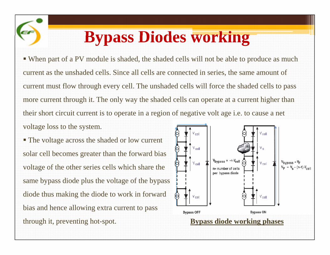
Bypass Diodes workingWhen part of a PV module is shaded, the shaded cells will not be able to produce as much
current as the unshaded cells. Since all cells are connected in series, the same amount of
current must flow through every cell. The unshaded cells will force the shaded cells to pass
more current through it. The only way the shaded cells can operate at a current higher than
their short circuit current is to operate in a region of negative volt age i.e. to cause a net
voltage loss to the system.
The voltage across the shaded or low current
solar cell becomes greater than the forward bias
voltage of the other series cells which share the
same bypass diode plus the voltage of the bypass
diode thus making the diode to work in forward
bias and hence allowing extra current to pass
through it, preventing hot-spot.
When part of a PV module is shaded, the shaded cells will not be able to produce as much
current as the unshaded cells. Since all cells are connected in series, the same amount of
current must flow through every cell. The unshaded cells will force the shaded cells to pass
more current through it. The only way the shaded cells can operate at a current higher than
their short circuit current is to operate in a region of negative volt age i.e. to cause a net
voltage loss to the system.
The voltage across the shaded or low current
solar cell becomes greater than the forward bias
voltage of the other series cells which share the
same bypass diode plus the voltage of the bypass
diode thus making the diode to work in forward
bias and hence allowing extra current to pass
through it, preventing hot-spot. Bypass diode working phases
Bypass Diodes working For an efficient operation, there are two conditions to fulfill:
1. Bypass diode has to conduct when one cell is shadowed.
2. The shadowed cell voltage Vs must stay under its breakdown voltage (Vc).
Ideally, a bypass diode should have a forward voltage (VF) and a leakage current (IR) as low
as possible.
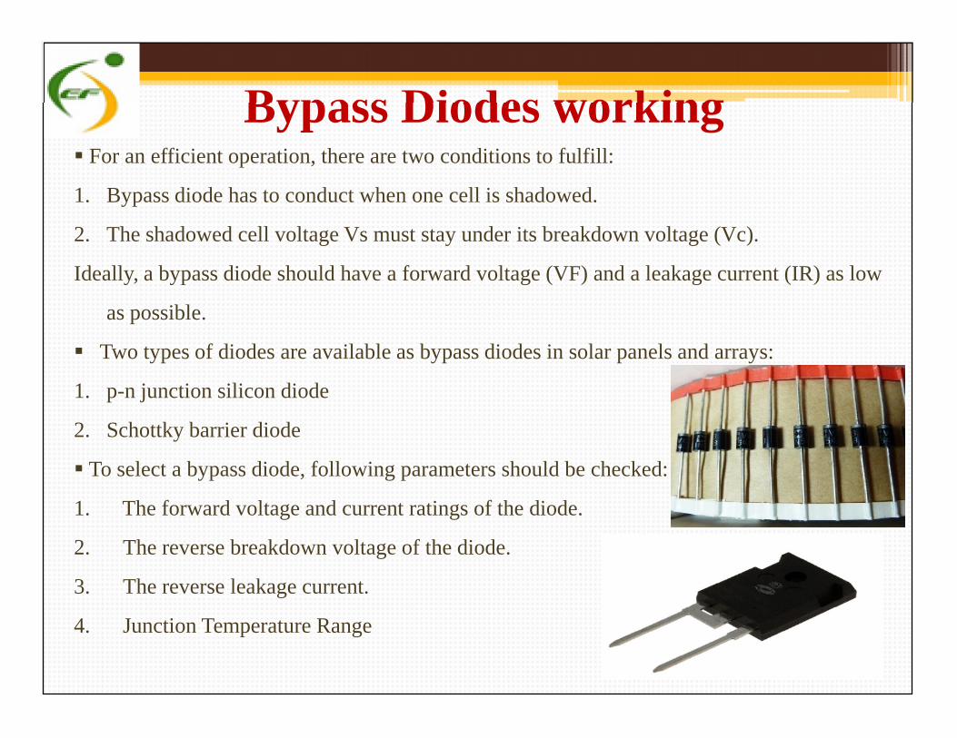
Two types of diodes are available as bypass diodes in solar panels and arrays:
1. p-n junction silicon diode
2. Schottky barrier diode
To select a bypass diode, following parameters should be checked:
1. The forward voltage and current ratings of the diode.
2. The reverse breakdown voltage of the diode.
3. The reverse leakage current.
4. Junction Temperature Range
For an efficient operation, there are two conditions to fulfill:
1. Bypass diode has to conduct when one cell is shadowed.
2. The shadowed cell voltage Vs must stay under its breakdown voltage (Vc).
Ideally, a bypass diode should have a forward voltage (VF) and a leakage current (IR) as low
as possible.
Two types of diodes are available as bypass diodes in solar panels and arrays:
1. p-n junction silicon diode
2. Schottky barrier diode
To select a bypass diode, following parameters should be checked:
1. The forward voltage and current ratings of the diode.
2. The reverse breakdown voltage of the diode.
3. The reverse leakage current.
4. Junction Temperature Range
Solar Panel specificationsMechanical Specifications:
1. Solar Cell Type: Defines the type of module or cell used in the module.e.g.- Mono-Si, Poly-Si or Thin Film.Design Implication: This determines the class of conversion efficiency of the module.
2. Cell Dimension (in inches/mm.): Defines the size of cell used in the module.e.g.- 125(l) × 125 mm(b) (5 inches).Design Implication: This determines the output power of a single solar cell.
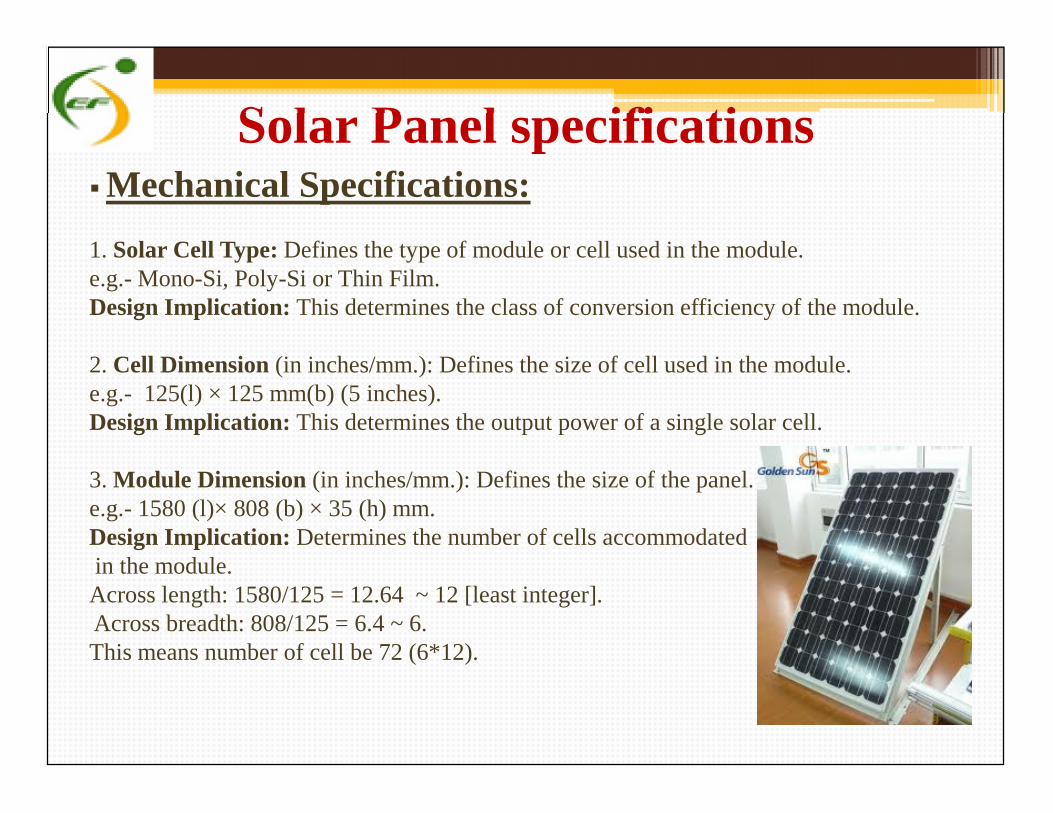
3. Module Dimension (in inches/mm.): Defines the size of the panel.e.g.- 1580 (l)× 808 (b) × 35 (h) mm.Design Implication: Determines the number of cells accommodatedin the module.Across length: 1580/125 = 12.64 ~ 12 [least integer].Across breadth: 808/125 = 6.4 ~ 6.This means number of cell be 72 (6*12).
Mechanical Specifications:
1. Solar Cell Type: Defines the type of module or cell used in the module.e.g.- Mono-Si, Poly-Si or Thin Film.Design Implication: This determines the class of conversion efficiency of the module.
2. Cell Dimension (in inches/mm.): Defines the size of cell used in the module.e.g.- 125(l) × 125 mm(b) (5 inches).Design Implication: This determines the output power of a single solar cell.
3. Module Dimension (in inches/mm.): Defines the size of the panel.e.g.- 1580 (l)× 808 (b) × 35 (h) mm.Design Implication: Determines the number of cells accommodatedin the module.Across length: 1580/125 = 12.64 ~ 12 [least integer].Across breadth: 808/125 = 6.4 ~ 6.This means number of cell be 72 (6*12).
Solar Panel specificationsMechanical Specifications:
4. Module Weight (in kgs./lbs.): Defines the weight of the module.e.g.- 15.5 kgs. (34.1 lbs.)Design Implication: Determines the maximum number of panels which can be installed.
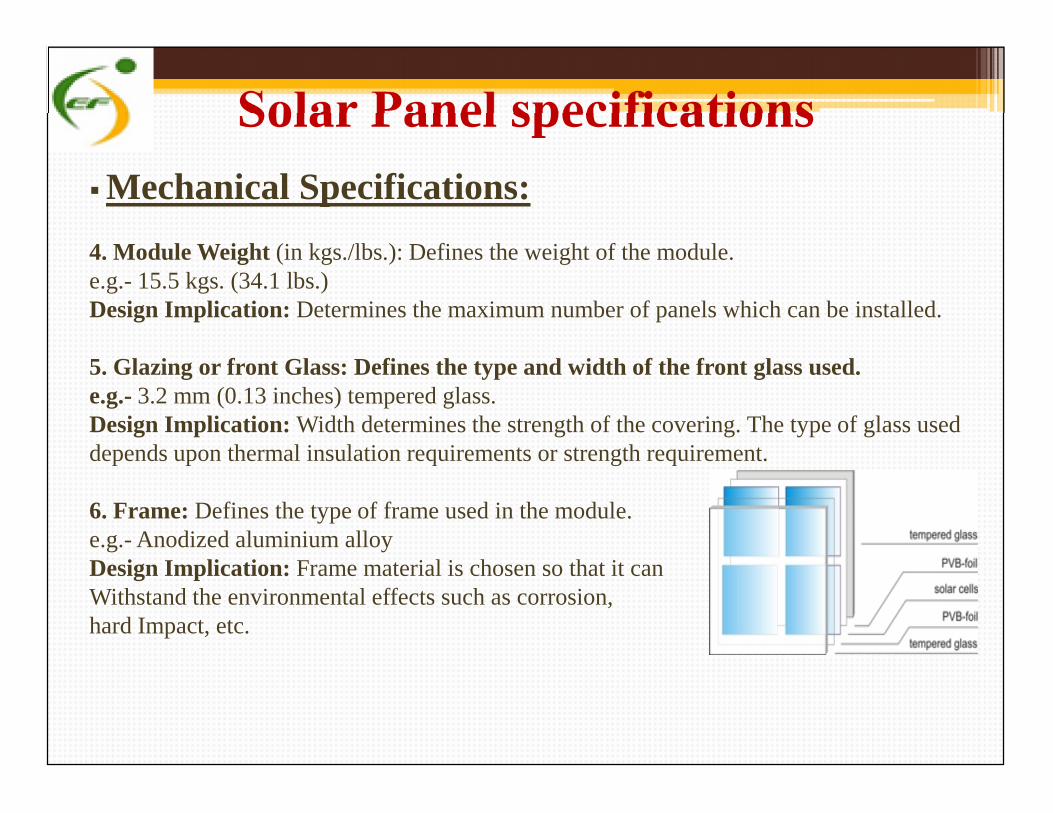
5. Glazing or front Glass: Defines the type and width of the front glass used.e.g.- 3.2 mm (0.13 inches) tempered glass.Design Implication: Width determines the strength of the covering. The type of glass useddepends upon thermal insulation requirements or strength requirement.
6. Frame: Defines the type of frame used in the module.e.g.- Anodized aluminium alloyDesign Implication: Frame material is chosen so that it canWithstand the environmental effects such as corrosion,hard Impact, etc.
Mechanical Specifications:
4. Module Weight (in kgs./lbs.): Defines the weight of the module.e.g.- 15.5 kgs. (34.1 lbs.)Design Implication: Determines the maximum number of panels which can be installed.
5. Glazing or front Glass: Defines the type and width of the front glass used.e.g.- 3.2 mm (0.13 inches) tempered glass.Design Implication: Width determines the strength of the covering. The type of glass useddepends upon thermal insulation requirements or strength requirement.
6. Frame: Defines the type of frame used in the module.e.g.- Anodized aluminium alloyDesign Implication: Frame material is chosen so that it canWithstand the environmental effects such as corrosion,hard Impact, etc.
Solar Panel specificationsMechanical Specifications:
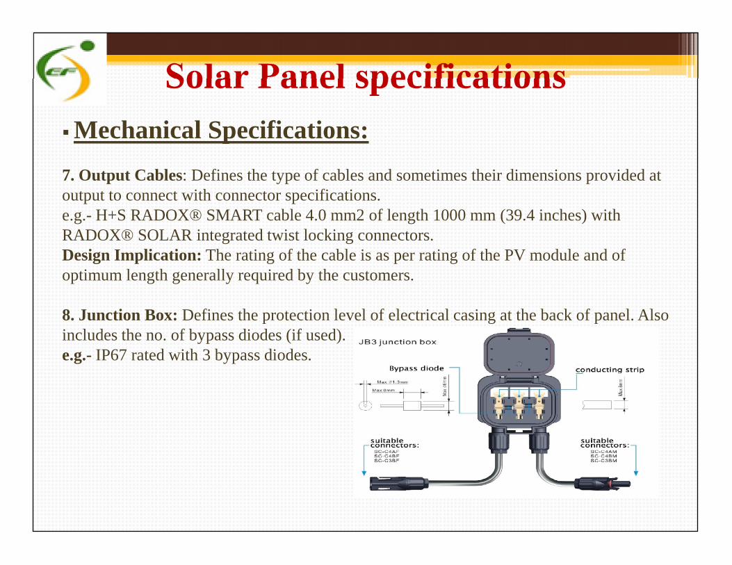
7. Output Cables: Defines the type of cables and sometimes their dimensions provided atoutput to connect with connector specifications.e.g.- H+S RADOX® SMART cable 4.0 mm2 of length 1000 mm (39.4 inches) withRADOX® SOLAR integrated twist locking connectors.Design Implication: The rating of the cable is as per rating of the PV module and ofoptimum length generally required by the customers.
8. Junction Box: Defines the protection level of electrical casing at the back of panel. Alsoincludes the no. of bypass diodes (if used).e.g.- IP67 rated with 3 bypass diodes.
Mechanical Specifications:
7. Output Cables: Defines the type of cables and sometimes their dimensions provided atoutput to connect with connector specifications.e.g.- H+S RADOX® SMART cable 4.0 mm2 of length 1000 mm (39.4 inches) withRADOX® SOLAR integrated twist locking connectors.Design Implication: The rating of the cable is as per rating of the PV module and ofoptimum length generally required by the customers.
8. Junction Box: Defines the protection level of electrical casing at the back of panel. Alsoincludes the no. of bypass diodes (if used).e.g.- IP67 rated with 3 bypass diodes.
Solar Panel specificationsElectrical specifications:
1. Peak Power (W): Defines the maximum power of the panel.e.g.- P: 195 WDesign Implication:
2. Optimum operating Voltage: Defines the highest operating voltage of panel at themaximum power at STC.e.g.- Vmp: 36.6VDesign Implication: Determines the number of panels required in series.
3. Optimum operating current: Defines the highest operating current of panel at themaximum power at STC.e.g.- Imp: 5.33ADesign Implication: Determines the wire gauge.Used to calculate the voltage drops across the modules or cells.
Electrical specifications:
1. Peak Power (W): Defines the maximum power of the panel.e.g.- P: 195 WDesign Implication:
2. Optimum operating Voltage: Defines the highest operating voltage of panel at themaximum power at STC.e.g.- Vmp: 36.6VDesign Implication: Determines the number of panels required in series.
3. Optimum operating current: Defines the highest operating current of panel at themaximum power at STC.e.g.- Imp: 5.33ADesign Implication: Determines the wire gauge.Used to calculate the voltage drops across the modules or cells.
Solar Panel specificationsElectrical Specs:
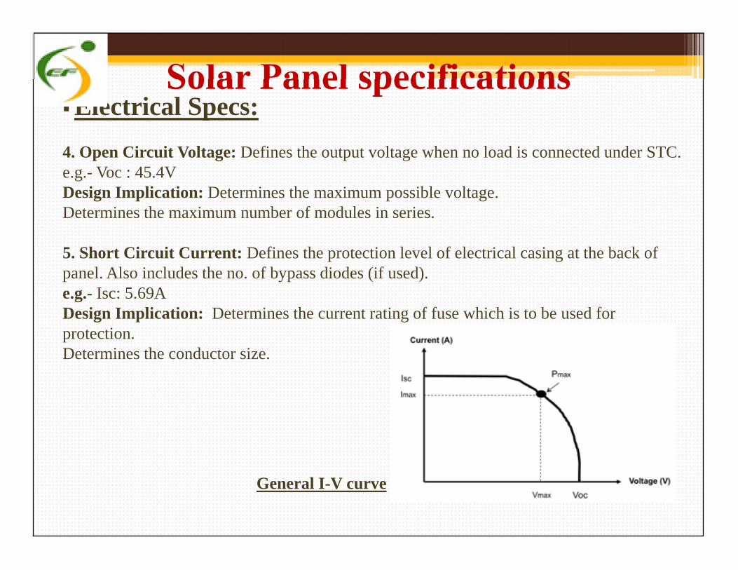
4. Open Circuit Voltage: Defines the output voltage when no load is connected under STC.e.g.- Voc : 45.4VDesign Implication: Determines the maximum possible voltage.Determines the maximum number of modules in series.
5. Short Circuit Current: Defines the protection level of electrical casing at the back ofpanel. Also includes the no. of bypass diodes (if used).e.g.- Isc: 5.69ADesign Implication: Determines the current rating of fuse which is to be used forprotection.Determines the conductor size.
Electrical Specs:
4. Open Circuit Voltage: Defines the output voltage when no load is connected under STC.e.g.- Voc : 45.4VDesign Implication: Determines the maximum possible voltage.Determines the maximum number of modules in series.
5. Short Circuit Current: Defines the protection level of electrical casing at the back ofpanel. Also includes the no. of bypass diodes (if used).e.g.- Isc: 5.69ADesign Implication: Determines the current rating of fuse which is to be used forprotection.Determines the conductor size.
General I-V curve
Solar Panel specifications Electrical Specifications:
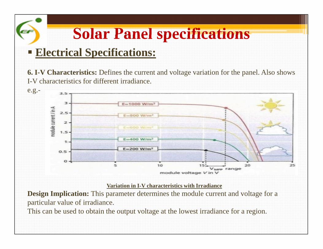
6. I-V Characteristics: Defines the current and voltage variation for the panel. Also showsI-V characteristics for different irradiance.e.g.-
Variation in I-V characteristics with Irradiance
Design Implication: This parameter determines the module current and voltage for aparticular value of irradiance.This can be used to obtain the output voltage at the lowest irradiance for a region.
Electrical Specifications:
6. I-V Characteristics: Defines the current and voltage variation for the panel. Also showsI-V characteristics for different irradiance.e.g.-
Variation in I-V characteristics with Irradiance
Design Implication: This parameter determines the module current and voltage for aparticular value of irradiance.This can be used to obtain the output voltage at the lowest irradiance for a region.
Solar Panel specifications Electrical Specifications:
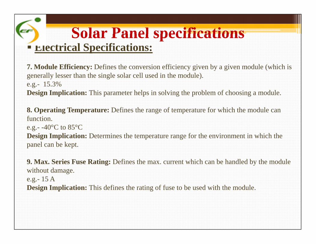
7. Module Efficiency: Defines the conversion efficiency given by a given module (which isgenerally lesser than the single solar cell used in the module).e.g.- 15.3%Design Implication: This parameter helps in solving the problem of choosing a module.
8. Operating Temperature: Defines the range of temperature for which the module canfunction.e.g.- -40°C to 85°CDesign Implication: Determines the temperature range for the environment in which thepanel can be kept.
9. Max. Series Fuse Rating: Defines the max. current which can be handled by the modulewithout damage.e.g.- 15 ADesign Implication: This defines the rating of fuse to be used with the module.
Electrical Specifications:
7. Module Efficiency: Defines the conversion efficiency given by a given module (which isgenerally lesser than the single solar cell used in the module).e.g.- 15.3%Design Implication: This parameter helps in solving the problem of choosing a module.
8. Operating Temperature: Defines the range of temperature for which the module canfunction.e.g.- -40°C to 85°CDesign Implication: Determines the temperature range for the environment in which thepanel can be kept.
9. Max. Series Fuse Rating: Defines the max. current which can be handled by the modulewithout damage.e.g.- 15 ADesign Implication: This defines the rating of fuse to be used with the module.
Solar Panel specifications Electrical Specifications:
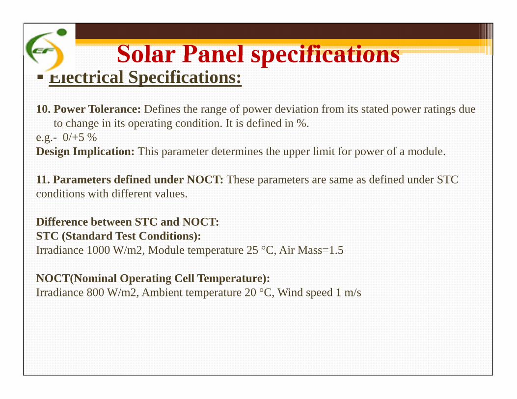
10. Power Tolerance: Defines the range of power deviation from its stated power ratings dueto change in its operating condition. It is defined in %.
e.g.- 0/+5 %Design Implication: This parameter determines the upper limit for power of a module.
11. Parameters defined under NOCT: These parameters are same as defined under STCconditions with different values.
Difference between STC and NOCT:STC (Standard Test Conditions):Irradiance 1000 W/m2, Module temperature 25 °C, Air Mass=1.5
NOCT(Nominal Operating Cell Temperature):Irradiance 800 W/m2, Ambient temperature 20 °C, Wind speed 1 m/s
Electrical Specifications:
10. Power Tolerance: Defines the range of power deviation from its stated power ratings dueto change in its operating condition. It is defined in %.
e.g.- 0/+5 %Design Implication: This parameter determines the upper limit for power of a module.
11. Parameters defined under NOCT: These parameters are same as defined under STCconditions with different values.
Difference between STC and NOCT:STC (Standard Test Conditions):Irradiance 1000 W/m2, Module temperature 25 °C, Air Mass=1.5
NOCT(Nominal Operating Cell Temperature):Irradiance 800 W/m2, Ambient temperature 20 °C, Wind speed 1 m/s
Solar Panel specifications Electrical Specifications:
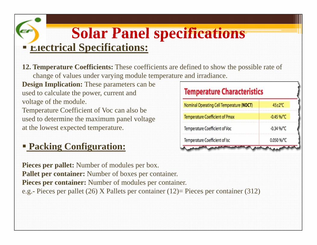
12. Temperature Coefficients: These coefficients are defined to show the possible rate ofchange of values under varying module temperature and irradiance.
Design Implication: These parameters can beused to calculate the power, current andvoltage of the module.Temperature Coefficient of Voc can also beused to determine the maximum panel voltageat the lowest expected temperature.
Packing Configuration:
Pieces per pallet: Number of modules per box.Pallet per container: Number of boxes per container.Pieces per container: Number of modules per container.e.g.- Pieces per pallet (26) X Pallets per container (12)= Pieces per container (312)
Electrical Specifications:
12. Temperature Coefficients: These coefficients are defined to show the possible rate ofchange of values under varying module temperature and irradiance.
Design Implication: These parameters can beused to calculate the power, current andvoltage of the module.Temperature Coefficient of Voc can also beused to determine the maximum panel voltageat the lowest expected temperature.
Packing Configuration:
Pieces per pallet: Number of modules per box.Pallet per container: Number of boxes per container.Pieces per container: Number of modules per container.e.g.- Pieces per pallet (26) X Pallets per container (12)= Pieces per container (312)
1/25/2013Submitted by: GouravKumar
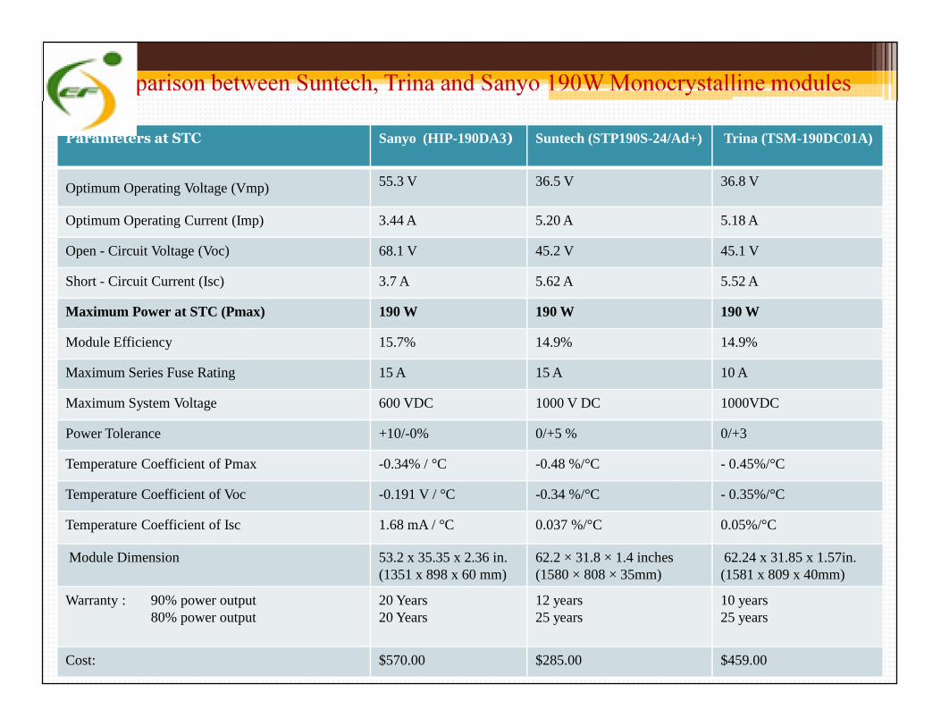
Comparison between Suntech, Trina and Sanyo 190W Monocrystalline modules
Parameters at STC Sanyo (HIP-190DA3) Suntech (STP190S-24/Ad+) Trina (TSM-190DC01A)
Optimum Operating Voltage (Vmp) 55.3 V 36.5 V 36.8 V
Optimum Operating Current (Imp) 3.44 A 5.20 A 5.18 A
Open - Circuit Voltage (Voc) 68.1 V 45.2 V 45.1 V
Short - Circuit Current (Isc) 3.7 A 5.62 A 5.52 A
Maximum Power at STC (Pmax) 190 W 190 W 190 W
Module Efficiency 15.7% 14.9% 14.9%
Maximum Series Fuse Rating 15 A 15 A 10 AMaximum Series Fuse Rating 15 A 15 A 10 A
Maximum System Voltage 600 VDC 1000 V DC 1000VDC
Power Tolerance +10/-0% 0/+5 % 0/+3
Temperature Coefficient of Pmax -0.34% / °C -0.48 %/°C - 0.45%/°C
Temperature Coefficient of Voc -0.191 V / °C -0.34 %/°C - 0.35%/°C
Temperature Coefficient of Isc 1.68 mA / °C 0.037 %/°C 0.05%/°C
Module Dimension 53.2 x 35.35 x 2.36 in.(1351 x 898 x 60 mm)
62.2 × 31.8 × 1.4 inches(1580 × 808 × 35mm)
62.24 x 31.85 x 1.57in.(1581 x 809 x 40mm)
Warranty : 90% power output80% power output
20 Years20 Years
12 years25 years
10 years25 years
Cost: $570.00 $285.00 $459.00

Parameters at STC Monocrystalline(S.C. Origin)
Polycrystalline(Moserbaer)
Thin Film (a-si)(China Solar)
Optimum Operating Voltage (Vmp) 17.82V 17 V 18 V
Optimum Operating Current (Imp) 0.285A 0.29A 0.278 A
Open - Circuit Voltage (Voc) 21.396V 21V 26.7 V
Short - Circuit Current (Isc) 0.315A 0.35A 0.401 A
Maximum Power at STC (Pmax) 5W 5 W 5 W
Module Efficiency 16.2% 14% Not Available
Comparison between Mono-, Poly- and Amorphous Si Solar Panels (5 W)
Module Efficiency 16.2% 14% Not Available
Temperature Coefficient of Pmax -0.549% (°K) -0.43 (°K) -(0.19±0.03)%/°C
Temperature Coefficient of Voc -0.397% /°K -0.344 %/°K -(0.34±0.04)%/°C
Temperature Coefficient of Isc 0.06% /°K 0.11 %/ °K 0.08±0.02)%/°C
Maximum System Voltage 1000 VDC 600VDC 600 VDC
Module Dimension 350x176x34mm 359x197x26 mm 385 x322 x18 mm
Warranty: 90% power output85% power output
10 years25 years
10 years15 years
10 years15 years
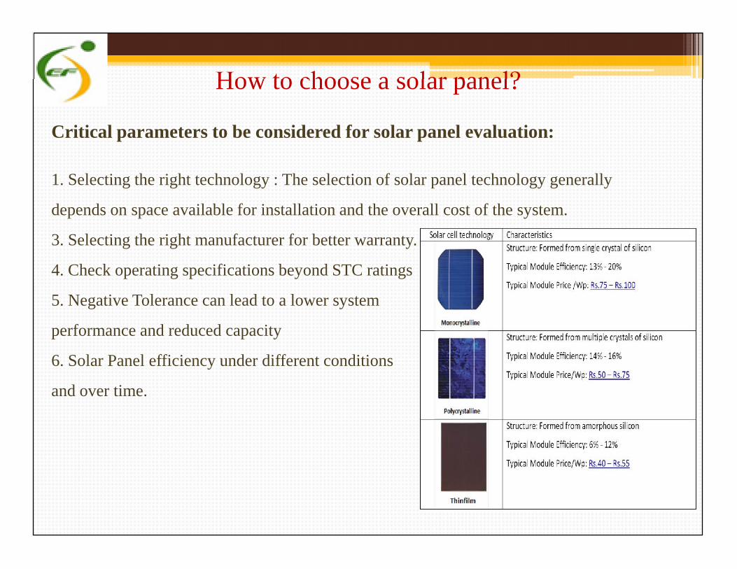
How to choose a solar panel?
Critical parameters to be considered for solar panel evaluation:
1. Selecting the right technology : The selection of solar panel technology generally
depends on space available for installation and the overall cost of the system.
3. Selecting the right manufacturer for better warranty.
4. Check operating specifications beyond STC ratings
5. Negative Tolerance can lead to a lower system
performance and reduced capacity
6. Solar Panel efficiency under different conditions
and over time.
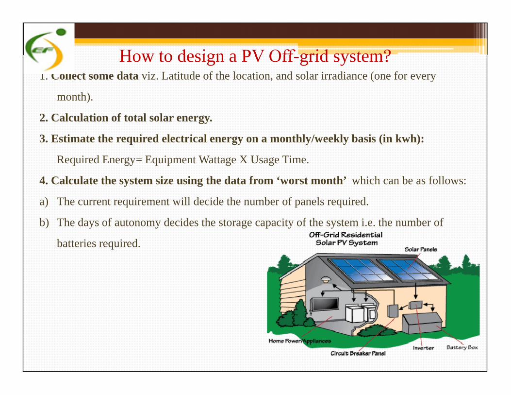
How to design a PV Off-grid system?1. Collect some data viz. Latitude of the location, and solar irradiance (one for every
month).
2. Calculation of total solar energy.
3. Estimate the required electrical energy on a monthly/weekly basis (in kwh):
Required Energy= Equipment Wattage X Usage Time.
4. Calculate the system size using the data from ‘worst month’ which can be as follows:
a) The current requirement will decide the number of panels required.
b) The days of autonomy decides the storage capacity of the system i.e. the number of
batteries required.
1. Collect some data viz. Latitude of the location, and solar irradiance (one for every
month).
2. Calculation of total solar energy.
3. Estimate the required electrical energy on a monthly/weekly basis (in kwh):
Required Energy= Equipment Wattage X Usage Time.
4. Calculate the system size using the data from ‘worst month’ which can be as follows:
a) The current requirement will decide the number of panels required.
b) The days of autonomy decides the storage capacity of the system i.e. the number of
batteries required.

• Registered Office:405 A, Prakrati Corporate, Y N Road, Indore(INDIA) 452001 • +91-731-6007860
• Chandigarh Office:SCO 48, 2nd Floor, Opposite P.O., Sector-8,Panchkula (INDIA) 134109 • +91-7696644244
• Mumbai Office:A1-1603, Runwal Garden City, Balkum, Thane (W),Mumbai (INDIA) – 400607
Email ID: [email protected]