a study of state-of-the-art large sized foam cutting rapid...
TRANSCRIPT

A Review of State-of-the-Art Large Sized Foam Cutting Rapid Prototyping and
Manufacturing Technologies
H. L. Brooks, D. Aitchison
Department of Mechanical Engineering, University of Canterbury, New Zealand
Abstract: Current additive rapid prototyping technologies fail to efficiently produce
objects greater than 0.5m³ due to restrictions in build size and build time. Conversely
large hot-wire cutting machines, able to cut large objects, often lack the ability to
create surfaces with complex geometrical features. Therefore there is a need to
develop rapid prototyping and manufacturing technologies capable of producing large
objects in a rapid manner directly from CAD data. Large sized freeform objects made
of soft materials, such as polystyrene foam, have numerous uses including; conceptual
design of commercial products, automotive design, aerodynamic and hydrodynamic
testing, advertising, film making, medical supports, sporting equipment and props for
the entertainment industry. Plastic foam cutting rapid prototyping is a relatively new
technology capable of producing large plastic foam objects directly from CAD data.
This paper will describe nine such technologies that have been developed or are
currently being developed at institutions around the world.
Introduction
Large sized freeform objects made from soft materials have numerous uses including;
conceptual design of commercial products, automotive design, aerodynamic and
hydrodynamic testing, advertising, film making, medical supports, sporting equipment
and the entertainment industry. One such soft material is polystyrene foam which
exists in two basic forms; Expanded Polystyrene (EPS) and Extruded Polystyrene
(XPS).
There are a number of well recognised manufacturing technologies capable of rapidly
producing complex objects or large objects but there are few that can do both with
low cost. Conventional additive rapid prototyping (RP) technologies are continuing to
improve in speed and accuracy, however the ability to produce large (> 0.5m³)
prototypes, moulds or parts is still expensive, time consuming and often impossible
[1]. CNC machining facilities are also used to machine objects with complex
geometries, however for most applications the cost of a large CNC machine may be
prohibitive. Also depending on the machine certain features (such as undercuts) may
require multiple setups or specialist tooling. Computer controlled foam cutting
machines have many attributes suited to large scale rapid prototyping and
manufacturing (RP & M) such as fast build times and low material costs [2].
However, the geometrical features able to be created on conventional foam cutting
machines are severely limited by the use of straight hot-wire cutting tools.
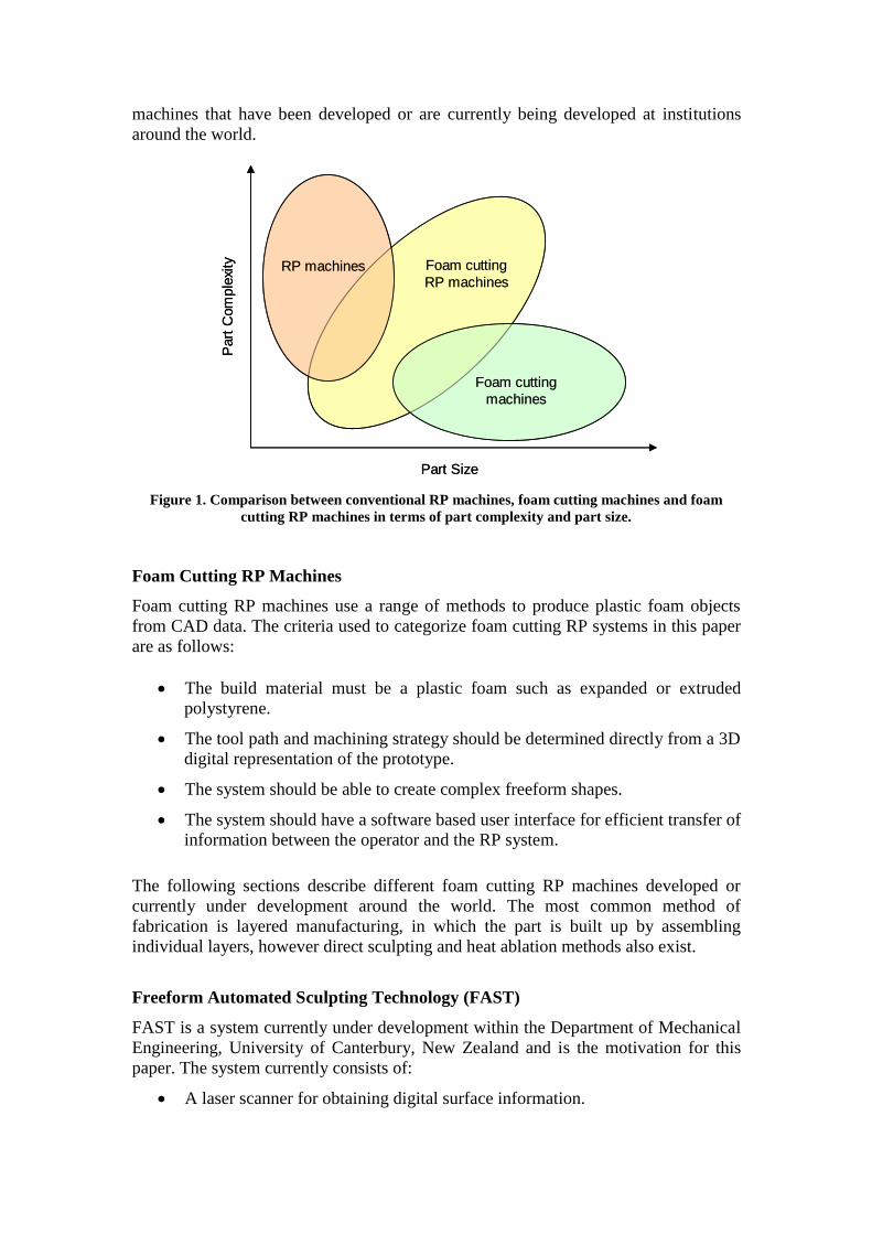
Foam cutting RP machines have been developed which enable the manufacture of
large and complex objects with low cost, they bridge the gap between conventional
RP machines and conventional foam cutting machines as is shown in figure 1.
Development of foam cutting machines for rapid prototyping and manufacturing (RP
& M) purposes began shortly after the first rapid prototyping machines became
commercialised in the late 1980s. However few RP foam cutting machines have been
commercialised to-date leaving significant opportunities for research and
development in this area. The following paper will describe novel foam cutting RP
machines that have been developed or are currently being developed at institutions
around the world.
Figure 1. Comparison between conventional RP machines, foam cutting machines and foam
cutting RP machines in terms of part complexity and part size.
Foam Cutting RP Machines
Foam cutting RP machines use a range of methods to produce plastic foam objects
from CAD data. The criteria used to categorize foam cutting RP systems in this paper
are as follows:
The build material must be a plastic foam such as expanded or extruded
polystyrene.
The tool path and machining strategy should be determined directly from a 3D
digital representation of the prototype.
The system should be able to create complex freeform shapes.
The system should have a software based user interface for efficient transfer of
information between the operator and the RP system.
The following sections describe different foam cutting RP machines developed or
currently under development around the world. The most common method of
fabrication is layered manufacturing, in which the part is built up by assembling
individual layers, however direct sculpting and heat ablation methods also exist.
Freeform Automated Sculpting Technology (FAST)
FAST is a system currently under development within the Department of Mechanical
Engineering, University of Canterbury, New Zealand and is the motivation for this
paper. The system currently consists of:
A laser scanner for obtaining digital surface information.
Part Size
Part
Com
ple
xity Foam cutting
RP machinesRP machines
Foam cutting
machines
Part Size
Part
Com
ple
xity Foam cutting
RP machinesRP machines
Foam cutting
machines
CAD/CAM software to prepare 3D models and produce cutting paths for the
robot.
A six axis Kuka KR6 industrial robot used to manipulate the cutting tool along
the cutting paths.
An electrically heated cutting tool used to cut the plastic foam.
This system is a form of robotic machining similar to that developed by Tangelder
[1]. The main difference is the use of a hot-ribbon as the cutting tool and the method
of producing the cutting paths.
The cutting elements used to date are 1/8” × 0.018” Nichrome ribbons which can be
pre-bent into any desired profile. In practice a jig is used to form blades with known
dimensions. Blades with large profiles are used for roughing while blades with
smaller profiles are used for detailed features and surfaces with high curvature. This
combination of tools greatly reduces cutting times when compared to standard milling
operations. A pneumatic gripper is used for automated tool changes, allowing many
different blade profiles to be used in a short time. Hot-wires can also be used for
profile cuts and objects with ruled surfaces.
A method for producing the robot control program was developed by Posthuma et al
[3, 4] in fulfilment of a Masters degree at the University of Canterbury. The process
starts with an IGES model which is loaded into CAM software MasterCAM™.
MasterCAM™ is then used to create roughing and finishing tool paths which are
processed using a modified generic 5-axis post processor. The tool path data is then
exported into an Excel spreadsheet where it is transformed into x y z A B C
coordinates which can be read by another proprietary software package called
RobotWorks™. RobotWorks™ is used to simulate the robot motion and carry out
collision and joint limit checks. RobotWorks™ then converts the tool path data into
Kuka language. The control program is then loaded into the robot PC and the program
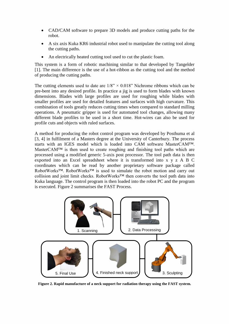
is executed. Figure 2 summarises the FAST Process.
Figure 2. Rapid manufacture of a neck support for radiation therapy using the FAST system.
1. Scanning
3. Sculpting 4. Finished neck support 5. Final Use
2. Data Processing

The FAST system has successfully sculpted a number of arbitrarily chosen freeform
surfaces out of EPS and XPS as well as custom fit supports trialled for medical
purposes. Figures 3 & 4 show some examples of parts sculpted with the FAST system
and relevant CAD models.
Figure 3. IGES model of neck support created from scanned data and the sculpted part ready for
use.
The IGES model shown below was generated by lofting between 5 arbitrary profiles.
These profiles were spaced 50mm apart to generate a surface with both concave and
convex features. Generating and processing the roughing and finishing tool paths took
approximately 40 minutes. The size of the foam blank was 160mm x 190mm x 50mm.
The roughing pass was carried out using a 25mm wide square profile Nichrome
cutting blade in 1.7 minutes. The finishing pass was carried out using an 8mm wide
flat ended Nichrome blade in 2.2 minutes. The total process time required to make the
part was 49 minutes.
Figure 4. IGES model and part sculpted from EPS showing complex 3D surfaces produced with
the FAST system.
Like many of the other systems included in this review research on the FAST project
is still ongoing and a number of improvements are envisaged for the future which will
dramatically increase the size, speed and accuracy of the system. These are expected
to include; streamlined data processing and robot code generation, optimised cutting
tool accuracy and tool path strategies and multi-axis workpiece manipulation. A
Sculpted artefact IGES model created from scanned data
IGES model Sculpted artefact

number of papers have been published by Aitchison et al investigation plastic foam
cutting mechanics with the purpose of increasing the speed, accuracy and surface
texture of cutting plastic foams with hot wires/ribbons [5-8].
True Surface System (Trusurf)
Trusurf is a layered manufacturing method developed by Hope et al at the Department
of Mechanical Engineering, University of Queensland, Australia [9]. The system was
developed primarily to produce large (> 1 m3) free-form models out of polystyrene
foam. It uses a high-pressure, 5–axis water-jet cutter to cut the model‟s cross-sections
from layers of polystyrene (10, 20 and 30 mm stock sizes). The 5–axis cutter cuts the
cross-sections with sloping edges (as opposed to vertical cuts) to eliminate the stepped
surface finish common to many LOM systems (see figure 5).
Figure 5. Stepped versus ruled cuts.
Once the thick cross-sections have been cut, they are assembled and bonded by hand
to produce the finished model. The advantage of the Trusurf system lies in the fact
that it can produce models with relatively thick layers as the linearly approximated
sides reduce the number of layers required for a given model.
The Trusurf system generates B-splines directly from CAD models (as opposed to
.STL files which are approximations of the CAD model surface) so the splines are
exact, hence the name Trusurf.
Figure 6 below shows two objects made with the Trusurf system. Because the water
cutter only produces linear approximations the surface finish is not ideal and
discontinuities are visible between the layers. The errors can be minimised by
decreasing the layer thicknesses although this also increases the build time.
Stepped surface Linearly approximated surface

Figure 6. Life size dolphin and revolved shape created with the Trusurf system.
Shapemaker I & II
Shapemaker I and II are layer based manufacturing systems developed by the
Manufacturing Processes Laboratory at the University of Utah [10, 11]. Shapemaker I
is a simple LOM based system in which section profiles are cut using a plotter and
manually stacked using a construction table and registration pins. After each
individual layer is stacked, the backing layer is peeled off, thus exposing the adhesive
and providing a bonding surface for the next layer. Materials used are paper, plastic
foam and vinyl sheet attached to a backing layer. Shapemaker I is now
commercialised as JP System 5 Desktop Rapid Prototyping by Schroff Development
Corporation, and is used primarily as an education tool introducing university students
to RP technologies. Figure 7 shows the JP System 5 and some paper models made
from it.
Figure 7. The JP-5 system and parts.
Shapemaker II (SMII) differs from its predecessor in that it is aimed at producing
large (>1m³) full scale prototypes from polystyrene foam. The foam is cut using hot-
wires which are attached to two plotting heads. The plotting heads move
independently to create linear approximations of each section surface similar to the
Trusurf system (in fact both were developed around the same time in 1996-1997).
Suggested applications of this technology include cores for large aerospace structures
which would then be finished and covered in a composite material. SMII was
successfully used to create a number of example objects including a wind turbine
blade and a tail rudder. The turbine blade measured 1.2m x 0.18m x 2.1m and the
fabrication time was approximately 11 hours excluding CAD modelling.

There are a number of limitations associated with SMII including:
The cutting wire can not be tilted more than 45° limiting the accuracy for
layers that require a larger slope.
Models that have features less than 1” can not be reproducing using the
required 1” thick foam.
The individual layers have to be assembled by hand using registration holes
and pins which could be cumbersome and time consuming.
ModelAngelo
This system was developed by the Department of Mechanical Engineering at the
American University of Beirut in Lebanon [12]. It consists of unique foam cutting RP
equipment and software collectively called “ModelAngelo”. ModelAngelo utilises a
combination of linear and rotational axis to cut foam with a heated cutting tool.
The foam blank is held in a lathe like fixture the motion of which is synchronised with
the cutting tool. Figure 8 shows the cutting tool, a part being sculpted and the
available degrees of freedom (for clarity the foam holding fixtures have been
emitted). The „γ‟ axis is used to rotate the foam part through a possible 90° to allow
the ends to be sculpted, however one end of the part must remain flat so it can be held
with clamping pins.
Figure 8. ModelAngelo apparatus.
The tool consists of two short stainless steel wires, which are electrically heated above
the melting point of the plastic foam used. The cutting tool is schematically illustrated
in figure 9. The outer loop is used to cut the foam while the inner loop is used to
manage the swarf. The inner loop is hotter than the outer loop because it does not
contact the foam. This causes the foam nearest the inner loop to melt and contract
curling the swarf upward. If the swarf is not removed from the cut surface it risks
sticking back to the model and would then need to be removed by hand.
z
r
θ
α γ

Figure 9. Electrically heated cutting tool.
The authors suggest a number of applications such as art sculpting, prototypes for fit
and form evaluation, and casting processes for biomedical and engineering
applications. Several finished products sculpted by ModelAngelo are shown in figure
10.
Figure 10. Parts sculpted using ModelAngelo.
Freeform Thick Layered Object Manufacturing (FF-TLOM)
This process is currently under development within the Faculty of Design, Deft
University of Technology in the Netherlands [2, 13-19]. The proposed system builds
models from XPS foam using a layered manufacturing method similar to the Trusurf
system. FF-TLOM utilises an electrically heated Nichrome blade to cut section
profiles which are then assembled manually.
The unique feature of this process is the flexible cutting tool which changes shape to
provide high order approximations of the desired surface as shown in figure 11. By
using higher order approximations it is possible to achieve far more accurate models
while using thicker layers. The cutting tool is a flexible Nichrome ribbon which is
held between two supports. The supports are accurately rotated with stepper motors to
change the shape of the ribbon to match the surface geometry. The ribbon shape for
any given support orientation is calculated using minimum strain energy theory.
A prototype of the flexible cutting tool is shown in figure 12, reproduced from [20].
The device has three degrees of freedom, the linear distance between the connection
points and the rotational orientation of the supports. The length of the ribbon between
the connection points is constant. A six axis Manutec R15 industrial robot was used to
manipulate the foam slab while the tool remained in a fixed position this is because
the prototype tool is rather large and heavy.
Cutting
direction
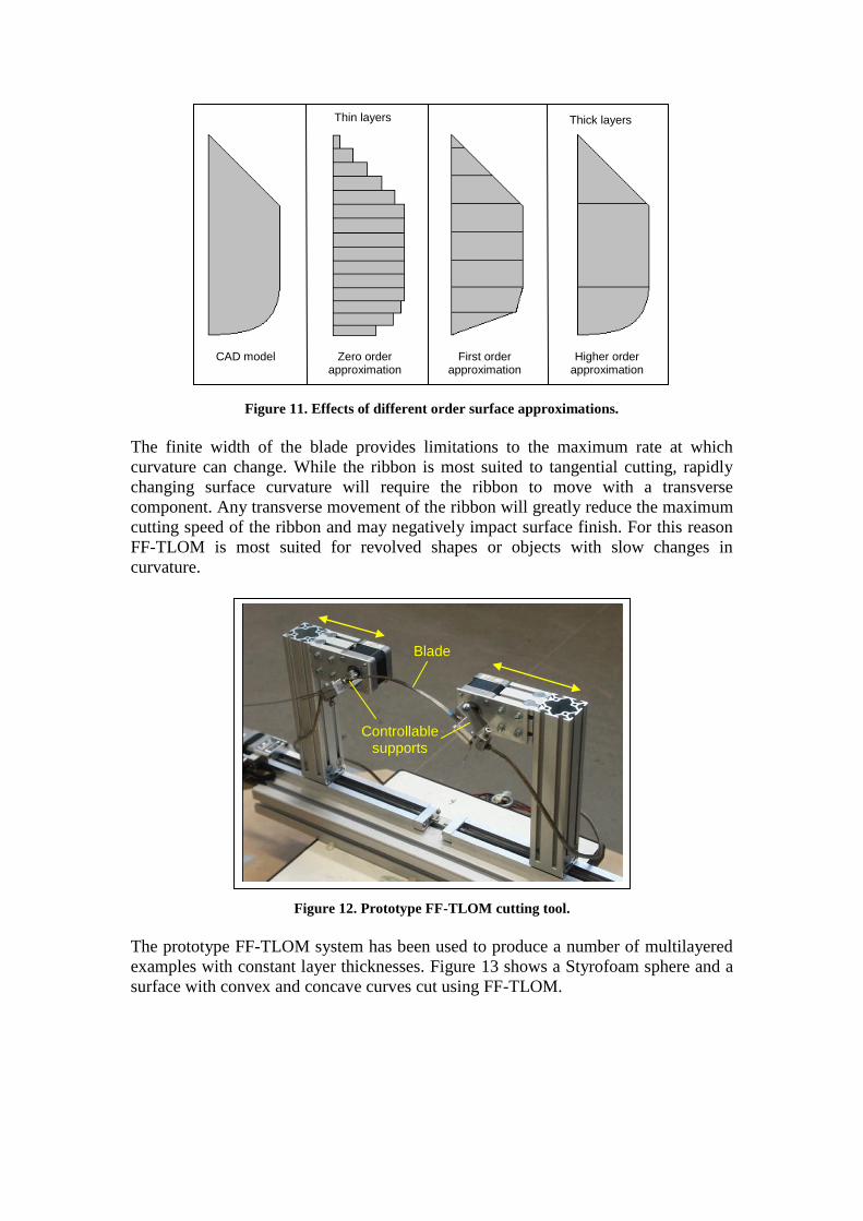
Figure 11. Effects of different order surface approximations.
The finite width of the blade provides limitations to the maximum rate at which
curvature can change. While the ribbon is most suited to tangential cutting, rapidly
changing surface curvature will require the ribbon to move with a transverse
component. Any transverse movement of the ribbon will greatly reduce the maximum
cutting speed of the ribbon and may negatively impact surface finish. For this reason
FF-TLOM is most suited for revolved shapes or objects with slow changes in
curvature.
Figure 12. Prototype FF-TLOM cutting tool.
The prototype FF-TLOM system has been used to produce a number of multilayered
examples with constant layer thicknesses. Figure 13 shows a Styrofoam sphere and a
surface with convex and concave curves cut using FF-TLOM.
Blade
Controllable supports
Thin layers
Higher order approximation
First order approximation
Zero order approximation
CAD model
Thick layers

Figure 13. Examples of FF-TLOM multilayered stacked assemblies.
Variable Lamination Manufacturing (VLM)
This system is currently being developed by Ahn et al at the Department of
Mechanical Engineering, Korean Advanced Institute of Science and Technology
(KAIST) in Taejon, Korea for which a number of papers have been published [21-25].
The published work details a number of investigations into hot-wire plastic foam
cutting mechanics based on both experimental and theoretical work.
The VLM system uses a hot-wire to cut out „thick‟ EPS cross-sections, which are
consequently bonded together to form the finished object. The hotwire cutter is
controlled within a four axis machine to cut sections with sloped edges similar to
Shapemaker II.
The main advantages of VLM over the Shapemaker II system is the material handling
process and the VLM can use foam layers of varying thicknesses. The process
consists of the following three main steps:
1. Material feeding and storing: EPS sheets (3.7-10 mm) are stored in a large roll
and fed into the cutting area via several sets of rollers. Rollers act to both
apply the bonding agent to the underside of the layer and to control the
thickness of the layer by exerting pressure. Controlled suction part holders
then hold the dimensionally accurate stock layer in place from above.
2. Shape generation: The next step involves cutting out the required shapes.
As can be seen from figure 14, the layers consist of several individual pieces
or unit shape parts (USP), which are assembled together like a jigsaw. The
joining edges in the feeding direction are cut with opposite 5º angles and are
staggered like brickwork in the transverse direction to improve the strength of
the finished object.

Figure 14 - Multi-piece layer concept
3. Stacking and bonding: Once the individual pieces have been cut out, they are
stacked on a controllable x-y table. Once a layer has been assembled the table
is moved below a pressing mechanism which is used to press the bonded
layers in order to enhance the bonded strength of the finished model.
The un-cut material is then cut off and removed by gravity and the steps are repeated
until the object is fully built. Figure 15 shows an example of a VLM produced part
and a reference part, built with laminated object manufacturing (LOM) technology,
used to evaluate the process.
Figure 15. CAD representation of a human head and comparison of the fabricated parts.
The authors conducted a comparison between their system and a conventional LOM
RP system using the human head shape. The following results, reproduced from [22],
are shown in table 1 below.
Table 1. Comparison between VLM and LOM.
Process
Building Time (min) Building Cost
(USD)
Dimensional Accuracy %
Set-up Building Decubing Total In Plane
(averaged) Z-dir
LOM 80 2125 120 2325 720 0.7 1.8
VLM - 35 5 40 8 0.8 1.1
CAD model VLM part LOM part
186.1
2 m
m

The VLM process has been commercialised by Menix Engineering Co., Ltd under the
Rapid Shaper product line. The VLM 300 produces parts using 3.7 mm thick A4
sheets of EPS while the VLM 400 uses 3.7, 5 and 10 mm thick A3 EPS sheets.
Figure 16. The Rapid Shaper range from Menix Engineering Co. Ltd based on technology
developed by the Korea Advanced Institute of Science and Technology.
Rapid Heat Ablation (RHA)
The researchers at KAIST (Kim et al) have also published a number of papers
describing a novel hot tool which is used to ablate plastic foams [26-28]. The process
which the authors call rapid heat ablation (RHA), involves the use of a specially
designed hot tool shaped similarly to a ball-end mill to create new surfaces by
ablating foam. The process has been used for creating fine detail on VLM parts which
can not be created with straight hot-wires. It can also be usedas a stand alone
manufacturing method. Figure 17 provides a schematic of the tool.
Figure 17. Schematic of RHA process.
The geometry of the RHA tool allows the tool path to be generated using conventional
CAM software for a ball-end mill. Also because the entire length of the tool can be
used to „machine‟ the material it is possible to carry out the finishing cuts without the
need for prior material removal. In a test carried out by the authors a large part was
shaped in 55 minutes compared to 430 minutes by a commercial milling machine.
This demonstrates a significant advantage can be gained by using RHA over
conventional machining when shaping plastic foams. Other advantages include:

Little to no swarf.
Better surface finish and accuracy (Ra values 1/10th
that of equivalent
machined parts).
Reduced machine time.
Figure 18 shows the RHA tool in action and a part produced by it.
Figure 18. RHA tool and part.
Michelangelo
Michelangelo is an eight axis foam sculpting system developed by Zhu et al from the
Tokyo Institute of Technology [29, 30]. It is composed of a six axis Motoman
industrial robot and a two axis worktable. It carves simplified EPS models that consist
of large flat faces with a hot-wire cutting tool.
A unique mesh simplification algorithm was created to reduce the complexity of the
model by reducing the number of facets used to define the surface. Figure 19 shows
an example of a model simplified using the mesh simplification algorithm. Once the
mesh is simplified to the desired resolution a tool path generation algorithm is used to
generate the tool path and a virtual reality simulation of the sculpting is run to ensure
all faces can be cut without robot/work piece interference.
Figure 19. Example of mesh simplification.
Original model 5804 triangles
Simplified model 500 triangles

By utilising a work table with an extra two degrees of freedom Michelangelo can
sculpt relatively large models with a small machine as reaching behind the part is not
an issue. Also because a hot-wire is used as the cutting tool the cutting process is
much faster than conventional machining practices. Figure 20 shows the robot and
worktable setup and a test part (shoe) produced by it.
Figure 20. 8 axis setup and a test part (shoe) produced by it.
In summary Michelangelo is an effective sculpting system for the generation of rough
objects. The unique mesh simplification algorithm and 8 axis robot system means
large objects can be sculpted quickly and to a user specified accuracy. However, a
number of disadvantages exist when applying this technology for more accurate
models. The system cannot sculpt features with fine detail, double concave surfaces or
pockets because of the straight hot-wire cutting tool.
Stratoconcept HW Series
The Stratoconcept HW series was developed through a collaborative effort between
Croma, a French based manufacturer of hot-wire foam cutting systems, and Cirtes, the
European centre of Rapid Prototyping and Tooling. This system uses a layer based
manufacturing method to manufacture high volume parts at high speed. The foam
parts include both interior and exterior details which allows for lightweight full scale
prototypes [31].
Croma adapted a cutting machine for the rapid manufacturing of foam products so
that it could implement Cirtes‟ software for layer based design and construction.
Cirtes‟ adapted its patented software based Stratoconception® rapid prototyping and
tooling process to be compatible with Croma‟s machine technology. The combined
process operates as follows:
1. A CAD model is imported in .STL or DXF 3DFace format and is decomposes
into 3D layers.
2. The system then automatically calculates the tool path for the 4 axis hot-wire
cutter and the „strata‟ are cut out. The surface of the layers are linear
approximations similar to that of the VLM process.
3. The final prototype is then manually assembled by stacking the layers and
aligning the inserts.

Figure 21 demonstrates the Stratoconception® process associated with the
Stratoconcept HWC and shows an example of an assembled full scale boat hull.
Figure 21. Example of the Stratoconception® process for the Stratoconcept HWC.
The Stratoconcept HWC series RP systems are ideally suited for manufacturing full
scale large prototypes from polystyrene foams. The largest machine in the series is
capable of producing parts with cross sections up to 5 m wide and 2.5 m tall with an
infinite length. The prototypes can be made hollow for lightweight manufacturing.
Inserts are used to align and strengthen the prototypes to withstand handling.
Disadvantages of the system include:
The final prototype must be assembled manually and glued.
Detail in the z direction must be larger than the standard thickness of the foam
stock.
The surface is a linear approximation of the input model meaning some post
processing may be required.
Some „expert‟ knowledge is required in placing the inserts and choosing the
„strata‟ orientation to maximise the strength of the prototype.
Summary of Foam cutting RP Machines
Nine different foam cutting RP machines were reviewed in order to provide a state-of-
the-art overview of recent technological advances in large scale foam cutting rapid
1. Sliced model
3. Stratoconcept HWC 4. Final Prototype
2. Section profile and tool path

prototyping technologies. The majority of modern foam cutting RP systems use
layered manufacturing to progressively build models from layers cut with hot-wires.
Other manufacturing methods include water jet cutting, hot-ribbon cutting and rapid
heat ablation. A small number of systems have been commercialised including the
VLM Rapid Shaper series by Menix Engineering Co. Ltd, and the Stratoconcept HW
series by Croma.
Figure 22 summarizes the difference in potential model size and model complexity
between the nine reviewed systems. The Stratoconcept HWC system has the largest
build volume with its largest machine capable of producing parts with a cross-section
of up to 6m² [32]. The VLM series machines are capable of producing the most
complex and accurate parts with dimensional errors up to 1.1% in the build direction
[22].
Part Size
Pa
rt C
om
ple
xity
FAST
Trusurf
SMII
ModelAngelo
FF-TLOM
VLM
RHA
Stratoconcept
Michelangelo
Part Size
Pa
rt C
om
ple
xity
FASTFAST
TrusurfTrusurf
SMIISMII
ModelAngeloModelAngelo
FF-TLOMFF-TLOM
VLMVLM
RHARHA
StratoconceptStratoconcept
MichelangeloMichelangelo
Figure 22. Qualitative comparison of complexity and size of parts made with nine foam cutting
RP machines.
Table 2 summarizes the different build strategies, cutting tools and relative build
times of the nine reviewed systems. It should be noted that the qualitative descriptions
given are relative to the foam cutting RP machines reviewed and not to RP processes
in general and only take into account the information presented in the referenced
papers. Also the build speed does not include assembly time for layer based methods.

Table 2. Comparison of foam cutting RP machines.
System Property
Cutting Tool Build Strategy Build Speed
FAST Hot-ribbon Direct sculpting 0
Trusurf Water jet Layer based 0
SM II Hot-wire Layer based 0
ModelAngelo Hot-wire Direct sculpting - -
FF-TLOM Hot-ribbon Layer based DATUM
VLM Hot-wire Layer based +
RHA Hot tool Direct sculpting -
Stratoconcept Hot-wire Layer based 0
Michelangelo Hot-wire Direct sculpting + +
Recommendations and Conclusions
All of the reviewed systems have proven themselves to be technically feasible;
however few have been developed to the commercial stage. This is partly due to
economic considerations and partly because many of the systems are still in the
developmental phase. To-date the most successful build strategy is to cut and
assemble individual layers, however with current advances in robotic machining this
may change. Direct sculpting with robots offers increased complexity and reduced
post-assembly of layers.
A number of unique ideas found in this review were deemed by the authors to be of
special importance to the development of future foam cutting RP systems and are
therefore listed here. These include:
For systems that use direct sculpting, the use of a two axis turntable to tilt and
rotate the work piece allows much greater reach-ability of the robot. This
would greatly increase the potential build volume of the system.
The innovative swarf management technique developed by Hamade et al with
ModelAngelo. This would prevent swarf produced by cutting with hot-
wires/hot-ribbons from rejoining the work piece.
The layer based manufacturing method adopted by most of the systems could
also be used to increase the size of parts built using the direct sculpting build
strategy.
The direct sculpting method could be applied to individual layers in the layer
based systems to avoid the need for surface approximations.
Many of the systems exhibited a high level of automation. In particular the
automatic generation of tool paths directly from the CAD model was common
among the systems. The automation of data creation (tool paths, control
programs etc.) is very important if the fast, reliable and automated production
of sculpted objects is to be realised.
Key: 0 = Same as Datum
- = Less than Datum
+ = Greater than Datum

References
[1] Johan Tangelder, "Automated fabrication of shape models of free-form objetcs
with a sculpturing robot," in Department of Computer Science Utrecht:
Utrecht University, 1998.
[2] J. Broek, I. Horvath, B. de Smit, A. Lennings, and J. Vergeest, "A Survey of
the State of Art in Thick Layered Manufacturing of Large Objects and the
Presentation of a Newly Developed System," in First International Seminar
and Workshop on Engineering Design in Integrated Product Development -
EDIProD'98, Zielona Gora, Poland, 1998, pp. IV-1..IV-12.
[3] A. Posthuma, "Development of a novel robotically effected plastic foam
sculpting system for rapid prototyping and manufacturing," in Department of
Mechanical Engineering. vol. M.E. Christchurch: University of Canterbury,
2007, p. 144.
[4] M. G. Taylor, "Semi-automated Robotic Sculpting of Freeform Surfaces for
Direct Digital Manufacture," in International Conference on Mechanical &
Manufacturing Engineeering (ICME2008), Johor Bahru, Malaysia, 2008.
[5] H. Brooks and D. Aitchison, "Thermal Plastic Foam Cutting Mechanics for
Rapid Prototyping and Manufacturing Purposes," in 9th National Conference
on Rapid Design, Prototyping and Manufacturing., Lancaster University,
2008.
[6] D. Aitchison, J. Bain, H. Brooks, A. Posthuma, and M. Taylor, "Transient
Temperature Effects in Hot-wire Plastic Foam Cutting," in 4th International
Conference and Exhibition on Design and Production of MACHINES and
DIES/MOLDS, Cesme, Turkey, 2007, pp. 219-224.
[7] D. Aitchison, H. Brooks, R. Kandula, B. Kraus, and M. Taylor, "Feed-rate,
Temperature and Feed-force Relationships for Foam Plastics Cut by a Taut
Hot-wire," in International Conference on Manufacturing Science and
Technology Melaka, Malaysia: Proceedings of ICOMAST2006, 2006.
[8] D. Aitchison and R. Sulaiman, "Determining the surface form of polystyrene
through the coordinate measurement machine," Proceedings of the Institution
of Mechanical Engineers, Part C: Journal of Mechanical Engineering
Science, vol. V217, pp. 839-844, 2003.
[9] R. L. Hope, Jacobs, P.A., Roth, R.N., "Rapid prototyping with sloping
surfaces," Rapid prototyping journal, vol. vol 3, pp. pp 12-19, 1997 1997.
[10] A. Novac, Kaza, S., Wang, Z., Thomas, C., "Techniques for Improved Speed
and Accuracy in Layered Manufacturing," in Proceedings of Solid Free-form
Symposium, Austin, Texas, 1996, pp. 609-617.
[11] C. L. Thomas, T. M. Gaffney, S. Kaza, and C. H. Lee, "Rapid prototyping of
large scale aerospace structures," in Aerospace Applications Conference,
1996. Proceedings., 1996 IEEE, 1996, pp. 219-230 vol.4.

[12] R. F. Hamade, F. Zeineddine, B. Akle, and A. Smaili, "Modelangelo: a
subtractive 5-axis robotic arm for rapid prototyping," Robotics and Computer-
Integrated Manufacturing, vol. 21, pp. 133-144, 2005.
[13] B. De Smit, J. Broek, and I. Horvath, "Experimental Investigation Of Factors
Influential For The Flexible Blade Based Prototyping Process," in The 1999
ASME Design Engineering Technical Conference, Las Vegas, Nevada, USA,
1999.
[14] I. Horvath, J. S. M. Vergeest, J. J. Broek, Z. Rusak, and B. de Smit, "Tool
profile and tool path calculation for free-form thick-layered fabrication,"
Computer-Aided Design, vol. 30, pp. 1097-1110, 1999.
[15] B. De Smit, J. Broek, I. Horvath, and L. Lennings, "Implementation of the
Freeform Thick Layered Object Manufacturing Technology (FF-TLOM), a
status review," in The 9th European Conference on Rapid Prototyping and
Manufacturing, 2000, pp. 311 - 321.
[16] B. De Smit, J. Broek, I. Horvath, A. Medland, and A. F. Lennings,
"Comparative Analysis and Experimental Verification of the Computed Shape
of a Flexible Blade Tool for FF-TLOM," in 5th ASME Design for
Manufacturing Conference, Baltimore, Maryland, USA, 2000.
[17] J. Broek, I. Horvath, and B. de Smit, "Exploration of Influential Parameters
for Speed Control of the Flexible Blade Cutting Process," in TMCE, Wuhan,
China, 2002.
[18] J. J. Broek, I. Horvath, B. de Smit, A. F. Lennings, Z. Rusak, and J. S. M.
Vergeest, "Free-form thick layer object manufacturing technology for large-
sized physical models," Automation in Construction, vol. 11, pp. 335-347,
2002.
[19] B. De Smit, A. Kooijman, J. Broek, and I. Horvath, "Developing a Tool for
the Direct Cutting of Freeform Surfaces out of Extruded Polystyrene Foam,"
in Euro-u Rapid 2002 Conference, 2002.
[20] B. De Smit, P. De Jager, A. Kooijman, and H. Broek, "Experimental Results
on the Application of FF-TLOM Technology for the Creation of a Large
Freeform Shape," Faculty of Design Engineering and Production, Deft
University of Technology, 2001.
[21] D. G. Ahn, S. H. Lee, and D. Y. Yang, "Investigation into thermal
characteristics of linear hotwire cutting system for variable lamination
manufacturing (VLM) process by using expandable polystyrene foam,"
International Journal of Machine Tools and Manufacture, vol. 42, pp. 427-
439, 2002.
[22] D. G. Ahn, S. H. Lee, and D. Y. Yang, "Development of transfer type variable
lamination manufacturing (VLM-) process," International Journal of Machine
Tools and Manufacture, vol. 42, pp. 1577-1587, 2002.

[23] D. G. Ahn, S. H. Lee, and D. Y. Yang, "Investigation into development of
progressive-type variable lamination manufacturing using expandable
polystyrene foam and its apparatus," Proceedings of the I MECH E Part B
Journal of Engineering Manufacture, vol. Volume 216, pp. pp. 1239-1252, 1
September 2002 2002.
[24] D. G. Ahn, S. H. Lee, and D. Y. Yang, "A study on the influence of the sloped
cutting angle on kerfwidth and part quality in the hotwire cutting of EPS foam
for the VLM- rapid prototyping process," International Journal of Machine
Tools and Manufacture, vol. 43, pp. 1447-1464, 2003.
[25] D.-G. Ahn, S.-H. Lee, and D.-Y. Yang, "Influence of process parameters on
the surface roughness in hotwire cutting of EPS foam sheet for VLM-S rapid
prototyping process," Journal of Materials Science, vol. 40, pp. 5699-5702,
2005.
[26] H. C. Kim, D. G. Ahn, S. H. Lee, and D. Y. Yang, "A study on thermal
characteristics of non-contact hot-tool for rapid feature detailing (RFD)
process," International Journal of Machine Tools and Manufacture, vol. 45,
pp. 345-353, 2005.
[27] H. C. Kim, S. H. Lee, and D. Y. Yang, "Development of a rapid heat ablation
(RHA) process using a hot tool," International Journal of Machine Tools and
Manufacture, vol. In Press, Corrected Proof, 2006.
[28] H. C. Kim, S. H. Lee, and D. Y. Yang, "A study of tool design for
minimization of heat-affected zone in rapid heat ablation process," Journal of
Materials Processing Technology, vol. 187-188, pp. 51-55, 2007.
[29] J. Zhu, R. Tanaka, T. Tanaka, and Y. Saito, "An 8-axis robot based rough
cutting system for surface sculpturing," in 11th International Conference on
Precision Engineering (11th ICPE), Tokyo, Japan, 2006, pp. p139-144
[30] J. Zhu, T. Tanaka, and Y. Saito, "3D mesh simplification for freeform
surfacing," in Tehran International Congress on Manufacturing Engineering
(TICME2005), Tehran, Iran, 2005, pp. (CD-ROM Proceeding).
[31] Cirtes, "Computer-Assisted Foam-Cutting Systems for Rapid Prototyping
Enhanced by Stratoconception Technology," in European Tool and Mould
Making, 2007, p. 22.
[32] Croma, "Foam Processing Technologies," http://www.croma-foamcutter.com/,
13/03/2008.