a study of austenite precipitate growth in duplex stainless steel.pdf
TRANSCRIPT
7/27/2019 A study of austenite precipitate growth in duplex stainless steel.pdf
http://slidepdf.com/reader/full/a-study-of-austenite-precipitate-growth-in-duplex-stainless-steelpdf 1/31
A Study of Austenite Precipitate Growth in Duplex Stainless Steel
A Research Performance EvaluationPresented by Eric Schmidt, PhD Candidate
Advisor: Dr. Sridhar Seetharaman
Introduction
As new experimental and characterization techniques are developed and improved, long-standing materials questions that have long been the subject of scientific debate are being
revisited and answered. Such questions have surrounded the mechanism of solid-state
phase transformation in ferrous systems for many years. Famous experimental andtheoretical works produced such well-known metallurgists as Clarence Zener, Mats
Hillert, Hubert Aaronson, and Rohit Trivedi (among many others) have now become the
basis for the application of a variety of new techniques that aim to shed new light on a
number of topics in this field. In the following presentation of a current study, severalaspects of the physical metallurgy of phase transformations are reviewed and a variety of
methods are examined in the context of austenite precipitation from ferrite in a duplex
stainless steel.
Current State of Knowledge
The velocity of an interface during a phase transformation can be summarized in thefollowing general equation:
( f v Interface = Thermodynamics, Diffusion, Interface Structure)
(1)
Each of these variables represents an important aspect of the phase transformation: the
velocity of the interface represents the kinetics of the transformation; thermodynamics provide the driving force for the transformation to take place; long-range diffusion of
substitutional and interstitial alloying elements, and also of vacancies (self-diffusion)must occur in order to maintain equilibrium in any multi-component system; energy is
required in order to create and maintain an interface of a particular shape and structure.

7/27/2019 A study of austenite precipitate growth in duplex stainless steel.pdf
http://slidepdf.com/reader/full/a-study-of-austenite-precipitate-growth-in-duplex-stainless-steelpdf 2/31
in an iron system are readily available and can be found in most current materials-based
metals handbooks. Due the multi-component nature of the duplex stainless steels which
are the basis for this study, these variables may become exceedingly complicated, butcomputer software like Thermo-Calc∗ and DICTRA
∗may be employed in order to make
evaluation possible.
Kinetics
The first widely accepted model for ferrite precipitate growth from austenite in iron-carbon alloys was first proposed by Zener [5] and later modified by Hillert [6] as
Ω−
Ω⋅=1
1
a D
v ρ where
α γ
γ α γ
x x
x x
−
−=
Ω−
Ω
1
1/
1(2)
Here, the thermodynamic driving force is represented by the supersaturation, Ω, which is
dependant on the initial composition of the austenite ( ), composition of austenite at
the interface ( ), and composition of the growing ferrite ( ). This driving force is
taken up by the requirement for diffusion of alloying elements to the interface ( ) and
by the curvature of the growing interface (
1γ x
α γ / x
α x
D
ρ ). Trivedi [7] further added to this model byincorporating interface kinetics and surface tension in the case of precipitate plates and
needles, resulting in a much more complicated relationship:
21
0
1
)(
1S S
v
v
perfce p cc p
⋅+⋅+Ω
=⋅⋅ ρ
ρ
π (3)
where p is the Peclet number, i.e.
D
v p
2
ρ = (4)
0Ω is a critical supersaturation that depends on the equilibrium composition of austenite
at a flat interface
α α γ
γ α γ
x x
x xe
e
−
−=Ω
/
1/
0 (5)
c ρ is a critical radius of curvature at which Ω and become zero, is a critical
l i hi h ll d i i f i di i d h i f hil S
v cv
d S
7/27/2019 A study of austenite precipitate growth in duplex stainless steel.pdf
http://slidepdf.com/reader/full/a-study-of-austenite-precipitate-growth-in-duplex-stainless-steelpdf 3/31
morphology. Evidence has been provided, however, as first proposed by Aaronson [9] in
his ledge growth theory, that in many circumstances an interface can only propagate by
means of even more complicated processes that involve interface structure at the atomicscale. These ledges are the first of a number of similar interface defects that have been
discovered which create strain energies, and require additional activation energies, duringgrowth. Significant work [e.g. 10,11,12,13] has been completed in incorporating these
processes into growth models for ledged interphase boundaries.
Classically, transformation kinetics have been studied through dilatometry [14,15].Experimental studies have also focused on studying the final as-transformed structures
[16,17]. Recent advances in hot-stage confocal microscopy have resulted in a number of studies of solid-state transformations in iron and its alloys [e.g. 18, 19], including recentstudies done by the present author [20, 21]. These studies presented real-time kinetic and
morphological observations and included an extensive review of previous work done in
the field of austenite formation from ferrite during heating.
Interface Structure
The interface structure determines the interfacial energy that results from broken bonds
and surface tension, may include strain energies that result from lattice mismatch between the parent and precipitate phase (which often result in the formation of defects),
and will also determine what kind of activation energies (in addition to those associated
with long-range diffusion) will be required for the migration of atoms across and/or defects along the interface boundary which are required for it to move. The investigation
of this structure at the atomic scale has become increasingly important in a
comprehensive analysis of precipitate growth. The Transmission Electron Microscope
(TEM) has been used to study interphase boundary structure in many alloy systemsincluding Fe alloys [e.g. 22,23], and specifically dual-phase stainless steels [23,24,25].These studies have been able to further characterize phase boundaries in terms of
coherency [e.g.24,25,26], invariant lines [e.g.26,27,28], dislocation arrays [e.g.29,30,31],
growth ledges [e.g. 26,32,33] (as well as any associated terraces and kinks), and a newlydescribed type of interfacial defect called a ‘disconnection’ [e.g. 34,35,36]. The theory
described in these papers has been summarized in the following paragraphs relating to
interface formation, structure, and migration.
The orientation relationship between parent and precipitate phases during solid-state
phase transformations has been widely studied; Dahman [37] has compiled a survey of
known OR’s in the FCC/BCC system, which is summarized here. Two of these OR’swhich have received the most attention, especially in the case of diffusional
transformations in iron alloys, are those first proposed by Kurdjimov and Sachs (K-S) in

7/27/2019 A study of austenite precipitate growth in duplex stainless steel.pdf
http://slidepdf.com/reader/full/a-study-of-austenite-precipitate-growth-in-duplex-stainless-steelpdf 4/31
the FCC lattice onto a <110> projection of the BCC lattice, and rotating appropriately to
line up the desired directions. These figures indicate two more sets of parallel directions
in each OR: <211> FCC/<211> BCC in K-S and <110>FCC/<100> BCC in N-W. Athird OR, proposed by Pitsch [41], is obtained by rotating from K-S around the parallel
<110>FCC/<111>BCC directions until a set of <100>FCC/<110>BCC directions become coincident (this has also been referred to as the inverse N-W OR). A closer
examination of the overlays indicates that there exists 4-fold symmetry about the closest-
packed plane normals for the N-W OR (The same exists in Pitsch, though not shown
here), while only 2-fold symmetry for K-S. An analysis of the different variants of parallel planes/directions in each OR indicates that there are 4 possible configurations of
the N-W and Pitsch OR’s, while there are 8 possible configurations of the K-S OR. Thusone might expect that, ceteris paribus, one would find the K-S OR twice as often as the N-W or Pitsch OR. Of course, other factors—the most important being the ratio between
lattice parameters of the FCC and BCC matrices—also affect the relative likelihood of
each OR in a particular system. One other OR of note is that of Greninger and Toriano(G-T) [42] which is intermediate between K-S and N-W, at a rotation of about 2.5
degrees from each around the close-packed plane normals.
The OR, however, provides only a small part of the information needed to characterize aninterface. All solid phase interfaces can be initially characterized in terms of coherency,
a measure of how well atoms of one crystal line up with a neighboring crystal at the
boundary between them. Howe et al [25] and Christian [26] provide an excellent basisfor a summary of the current understanding of interface structure. In a coherent
interface, atoms on either side of the interface have exactly the same planar structure and
spacing, such that each atom at the interface can bond with an atom on the other side.
Coherent interfaces have a relatively low energy and are generally immobile. In partlycoherent interfaces, there is a misalignment of these planar structures and/or a differencein lattice spacing which causes discontinuity and results in misfit-compensating defects
[37] that may require varying degrees of energy to maintain. Incoherent interfaces do not
have any long range order and have the highest energy of the three. While the twoneighboring crystals need not have different structure to be characterized in this way—
grain boundaries in a polycrystalline material, for example—this study will focus on
boundaries between the FCC and BCC phases of iron.
In order to determine the coherency of an interface we must also know the orientation of
the habit plane; that is, the actual plane along which the parent and precipitate phases
meet. Habit planes can be described as rational or irrational, depending on whether or not the indices of the plane are integer values. Generally, high index habit planes can be
reduced to a system of terraces, ledges, and/or kinks made of low index surfaces. Certain
7/27/2019 A study of austenite precipitate growth in duplex stainless steel.pdf
http://slidepdf.com/reader/full/a-study-of-austenite-precipitate-growth-in-duplex-stainless-steelpdf 5/31
Such dislocations are similar to misfit dislocations resulting from lattice mismatch during
epitaxial growth of a thin film on a substrate. During migration of an interface, these
dislocations become mobile; when two dislocations with burger’s vectors of oppositesign meet, they are annihilated. The result of this annihilation is called a ‘disconnection’.
This is an energetically favorable event, as it further relaxes lattice strain on both sides of the interface. If the transformation disconnection has both dislocation and ledge
character, it is referred to as a structural ledge. In general, a partly coherent interface will
be surrounded by arrays of dislocations in the parent and precipitate matrix, composed of
terraces, bounded by ledges (structural or otherwise) and kinks, and containing arrays of misfit dislocations and transformation disconnections. If the density of defects increases
to the point where the spacing between dislocations required for full relaxation of aninterface approaches the dislocation core size, the interface becomes incoherent (i.e.completely relaxed).
When there is no coherency, an interface needs only to be in thermodynamic equilibrium,and atoms need only to jump across the boundary and join the crystal structure on the
other side for migration to take place. Such transformations are generally referred to as
‘reconstructive’, that is to say that atoms from one phase with one structure reform across
the interface as a second phase with a different structure. Atoms do not form bondsacross the interface, and because activation energies for atoms to make such a jump is
relatively low the migration rate in an alloy is usually controlled by long range diffusion
in the parent or precipitate phase. The growth direction of such an interface is notconstrained by structural features. As previously mentioned, incoherent interfaces
require the most energy to form due to the lack of bonds.
Partially coherent interfaces require less energy to form than incoherent interfaces
because fewer bonds have been broken. However, structural ledges that have beenrelaxed by the formation of misfit dislocations and transformation disconnections in order
to increase coherency among as many of the atoms across an interface as possible cannot
migrate easily. These interfaces require the motion of steps and kinks along the habit plane, as well as the long-range diffusion of alloying elements to maintain
thermodynamic equilibrium, in order for growth to occur. The motion of steps and kinks
may also require climb of screw dislocations, and so diffusion of vacancies to and from
the interface may also become important. Also, as a result of the orientation of suchdefects and the preferential habit planes in which they exist, growth occurs in certain
directions at a much faster rate and the precipitates that form in such a manner will have
characteristic shapes such as plates and laths.

7/27/2019 A study of austenite precipitate growth in duplex stainless steel.pdf
http://slidepdf.com/reader/full/a-study-of-austenite-precipitate-growth-in-duplex-stainless-steelpdf 6/31
the other hand, any a posteri studies have relied on the transformation of austenite to
martensite during a rapid quench, leaving a ferrite plus martensite microstructure and
retaining no growth interfaces. In order to determine an orientation relationship (OR) of ferrite precipitates with the surrounding (prior) austenite matrix or (prior) austenite
precipitates with the surrounding ferrite matrix, it is necessary to extract the austeniteorientation in a secondary manner based on martensite grain orientations [e.g. 43].
Conveniently, interface structure and OR in duplex stainless steels, which are preserved
upon quenching, can be studied directly through high resolution microscopy and
diffraction [44, 45, 46] after high temperature kinetic observations. Therefore, theobjectives of this study are to
1. Compare and analyze the observed kinetics, morphology, and interface structure of agrowing precipitate with respect to the thermodynamics and transport requirements
associated with the transformation.
2. Produce important evidence that could lead to the improvement of current models for
solid state precipitate growth.
Approach
In order to achieve the objectives set forth, a proper material must be chosen and avariety of experimental techniques must be employed and mastered. Therefore, an
introduction to duplex stainless steels, and a clear explanation for their applicability to
this study is provided. High temperature confocal microscopy is employed to measuredirectly the kinetics of an evolving microstructure. Electron microscopy, electron
diffraction analysis, and quantitative x-ray analysis are essential for the subsequentcharacterization at multiple scales of resolution.
Material
Dual-phase (or duplex) stainless steels are a relatively new grade of material which
exhibit an excellent mix of the toughness and workability of austenitic grades with the
higher strength of ferritic grades that result from a 50/50 mixture of the two phases.
These steels also reduce costs by exhibiting excellent pitting resistance at a much lower nickel content. The duplex microstructure is obtained by a employing a careful mix of
high chromium (18-28 wt%) and nitrogen (0.05-0.35 wt%) with low to moderate nickel
(2.5-8 wt%). Kinetic data (i.e. CCT, TTT diagrams) [47] for these alloys indicate that aquench rate greater than 5 K/s from the two-phase γ + δ region below the solution
temperature can prevent deleterious intermetallic (σ, χ ), and chromium-rich secondary
7/27/2019 A study of austenite precipitate growth in duplex stainless steel.pdf
http://slidepdf.com/reader/full/a-study-of-austenite-precipitate-growth-in-duplex-stainless-steelpdf 7/31
at a temperature such that an equal amount of austenite and ferrite are present. The
material used in this study is no exception, and careful polishing of the surface reveals a
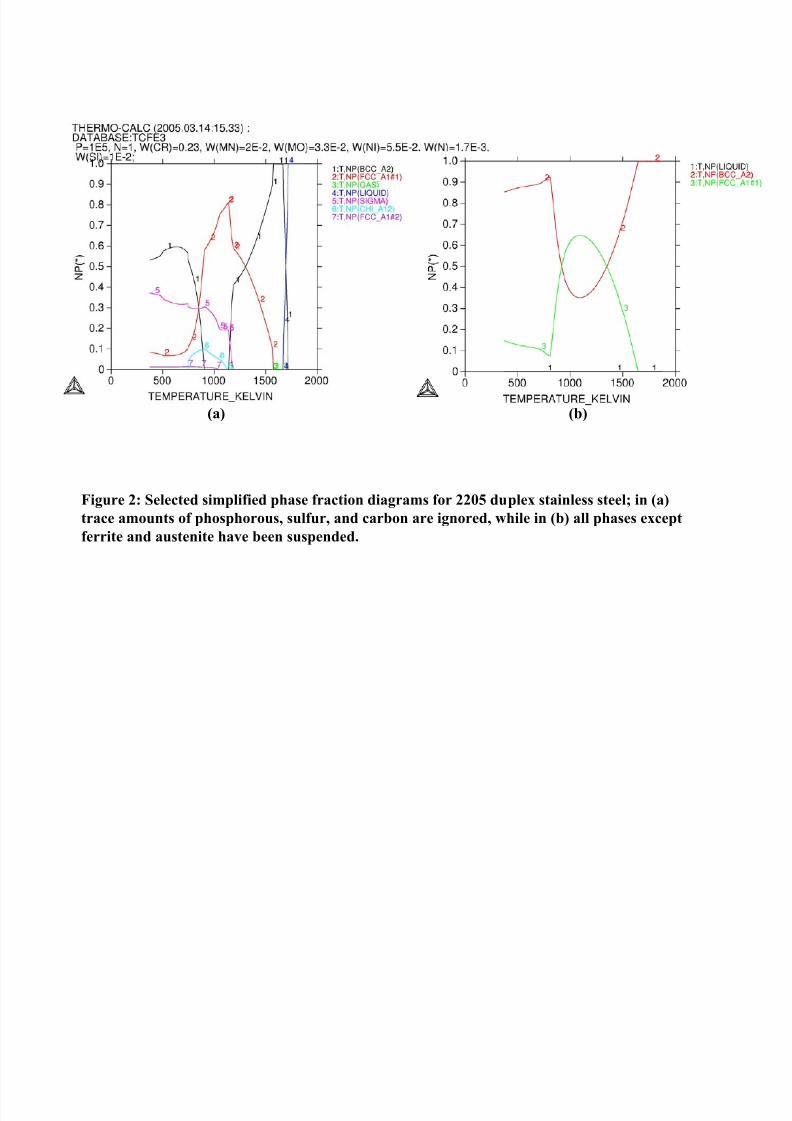
relatively even mixture of each phase. Phase fraction diagrams, which indicate theamount of each phase expected to be present as a function of temperature, were created
using Thermo-Calc software. In order to simplify these diagrams to some extent, someminor alteration to chemistry or suspension of certain complex equilibrium phases has
been allowed. In Figure 2(a), the number of possible precipitate phases is reduced by
eliminating the trace amounts of carbon, sulfur, and phosphorous. In Figure 2(b) all of
the trace elements are included, but all of the solid phases other than austenite and δ-ferrite/α-ferrite have been suspended—this is essentially a metastable phase diagram. It
is expected that the experimentally observed temperature for transformation, duringsignificantly fast heating/cooling rates when only austenite and ferrite are present, shouldfollow closely the phase fraction diagram in Figure 2(b). During extended isothermal
holds, however, the diagram in Figure 2(a) should provide a better prediction of how
much and at what temperature each phase will form. This will also provide adequatewarning with regard to minimum temperatures at which undesirable intermetallics, which
would ruin our preserved two-phase structure and composition, are not be expected to
form.
Growth Kinetics
Transformation kinetics are measured experimentally through the use of a Confocal
Scanning Laser Microscope (CSLM) with a hot stage. The CSLM also allows the precipitate morphology (e.g. tip radius, aspect ratio, interface shape) to be observed
during the transformation and quantified. The principle of its operation has been detailed
in a number of published studies [e.g. 18-21,48]. Confocal optics, shown in Figure 3a,
enable the detection of a strong signal from the focal plane while decreasing the intensity
of signals not in the focal plane. A screen with a pin hole deflects any signals thatoriginate at locations above or below than the focal point, or on any surface which is not
perpendicular to the laser, and thus an image is created, with a ~5-10 µm depth of field.
The depth of field results from the variation of signal strength with elevation, roughness,or inclination, and is based primarily on the topography of the surface being viewed.
Because this depth of field is fairly narrow, very small changes in elevation, inclination,
or roughness will cause noticeable changes in signal strength. Thus the CSLM becomes
an adequate, if not ideal, tool for observing the growth of precipitates in which any of thefollowing processes occur: (i) surface deformation caused by the displacive nature of a
phase transformation [e.g. 49,50], (ii) thermal grooving at free surfaces [51], (iii) surface
diffusion leading to smoothing of the surface [52], (iv) local dilatometric changes due todifferences in density between two phases, and perhaps (v) changes in absorption or
scattering of laser radiation resulting from a change in optical properties inherent to

7/27/2019 A study of austenite precipitate growth in duplex stainless steel.pdf
http://slidepdf.com/reader/full/a-study-of-austenite-precipitate-growth-in-duplex-stainless-steelpdf 8/31
on the sample, which is located at the upper focus of the elliptoid. Because the laser
radiation used to form the image is much more intense than thermal radiation from the
sample, and because the pin hole mentioned earlier is also able to deflect out of phaseradiation that does not originate from the laser, a clear image of the surface can be
obtained. The temperature is measured by a thermocouple placed near the surface of thesample. The response of this thermocouple is also used to control the intensity of the
heating lamp, and the temperature profile during an experiment can be programmed as
desired.
A vacuum pump and gas delivery system are used in tandem to evacuate the furnace of
undesired gases before an experiment and provide a constant atmosphere of desiredcomposition during an experiment. An atmosphere of flowing helium gas is capable of cooling the sample from the annealing temperature at greater than 10 K/s throughout the
critical temperature region and can thus preserve the high temperature microstructure.
The gas used in this study is grade 5.0 He, and has been passed through a gas cleaningsystem as follows: one steel tube filled with silica dessicant to remove any moisture and
three steel tubes wrapped with heating tape and ceramic fiber insulation; one filled with
copper turnings (T~700ºC) and the next two filled with magnesium chips (T~600ºC).
The furnace chamber is repeatedly evacuated and refilled with the purified He gas fromthe gas cleaning system, which was subsequently allowed to flow for 1 hour. The oxygen
potential was measured in the inlet and outlet gas streams by a ceramic oxygen sensor in
order to ensure that appreciable oxygen leaks were not present. Generally a constant (towithin one order of magnitude during an experiment) Po2 of less than 10
-15atm is
maintained. The flow rate during an experiment is on the order of 1 L/min to ensure
adequate cooling rates can be achieved when necessary.
The sample is then subjected to a programmed thermal profile while an image of thesurface was continuously recorded in video recorder at a rate of 30 frames per second.
Samples are initially heated at a rate of 10 K/s to a soaking temperature of 1300ºC (1573
K), where the phase diagram indicates a fully δ-ferrite region, and held for 3 minutes.This is followed by a rapid quench (~20 K/s) to a variety of temperatures, ranging from
1100ºC down to 900ºC, and an isothermal hold for up to 30 minutes during which
austenite is expected to precipitate from the ferrite matrix. The heating lamp is then
turned off, and samples return to ambient temperature within approximately 45-60seconds. Due to the large size (~1-2 mm) of the δ-ferrite grains formed during the high
temperature soak, individual grains can be identified with the naked eye and marked with
a scribe to locate observed regions for subsequent characterization. The recorded videosof the surface are subsequently digitized, analyzed, and from which still images can be
extracted using MGI VideoWaveTM
software.

7/27/2019 A study of austenite precipitate growth in duplex stainless steel.pdf
http://slidepdf.com/reader/full/a-study-of-austenite-precipitate-growth-in-duplex-stainless-steelpdf 9/31
solution for 20 minutes. The EBSD system used in this study is composed of a Philips
XL-20 SEM, a digital camera and lens which collects electron diffraction patterns, and
TexSEMTM
OIM data collection software. Scan files obtained are analyzed withTexSEM
TMOIM analysis software. For this study, the analysis software is used to
produce inverse pole figure (IPF) color maps of an entire surface, and various polefigures of individual points from such a map. The collection software is capable of
differentiating between multiple phases, and thus comparisons of selected pole figures
can be obtained for any set of parent/precipitate phase points. In certain cases, the IPF
maps are cleaned up using AdobeTM
Photoshop software, for illustrative purposes. Nocolors are changed, only noise has been deleted and replaced with the surrounding color.
Photoshop is also used to analyze multiple images: IPF images are superimposed ontoconfocal stills, and selected pole figures from points in precipitate and parent phase can be overlaid to check for common points.
An SEM equipped with EDX/WDX system and using QuantMapTM
software is used tomeasure partitioning of alloying elements between phases. The sample is not prepared
further after a CSLM experiment, so that topographical clues can be used to locate
specific precipitates and boundaries during this analysis. The QuantMap program
produces a series of images which show relative amounts of each element across asurface, and provides full compositional analysis data at an individual point chosen from
the SEM image of the surface.
Preliminary Results
In-Situ Observations and Analysis of Kinetic Data
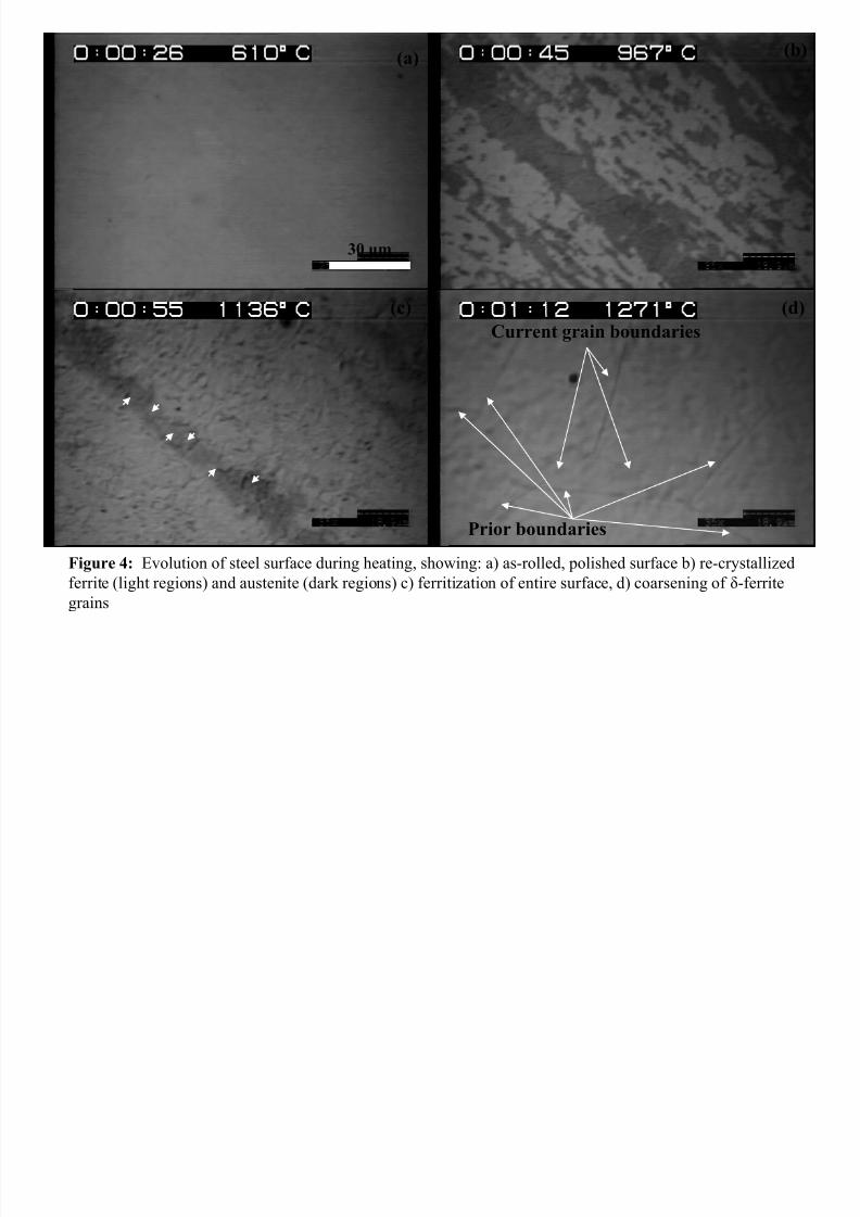
During heating of the 2205 sample from ambient temperature to the high temperatureanneal, a number of interesting processes were observed. While dark and light regions of
nearly even amounts were faintly visible on an as-polished sample when it was first
placed in the microscope (Figure 4a), these regions became much more apparent as thetemperature increased (Figure 4b). As the sample is heated beyond the solution
annealing temperature (at which an even mixture of ferrite and austenite are expected)
and ferritization should occur, the light regions eventually consume the darker regions
(Figure 4c). As a result of these observations, it is concluded that the light regions areferrite and the dark regions are austenite. When the sample is fully ferritized and the
temperature approaches 1300ºC, coarsening of the ferrite grains begins to occur (Figure
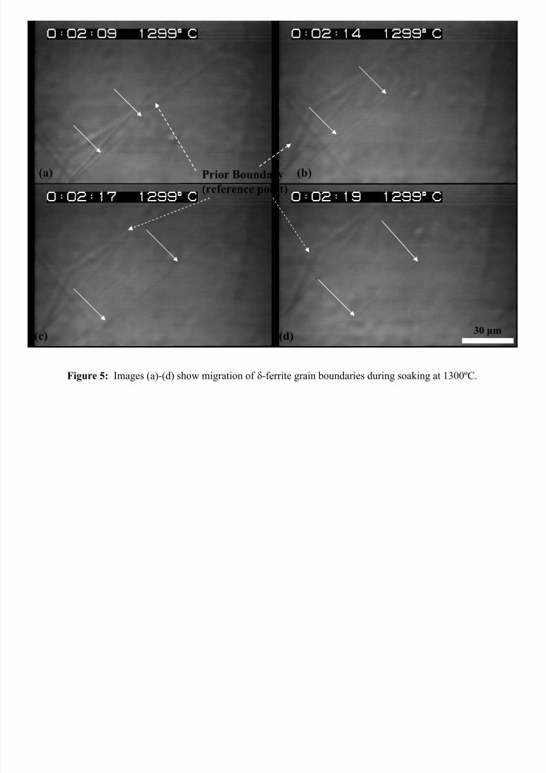
4d). Coarsening is a very rapid process, and thermally etched grain boundary groovesmay only last for a second or two. During the hold at 1300ºC, and once the coarsening
process has slowed down to some extent, these grooves, and apparently the grain
7/27/2019 A study of austenite precipitate growth in duplex stainless steel.pdf
http://slidepdf.com/reader/full/a-study-of-austenite-precipitate-growth-in-duplex-stainless-steelpdf 10/31
non-metallic inclusions, and/or at the groove itself. When boundaries could become
unpinned, they would rapidly move to a new position (no grooving was visible during
this migration), and become pinned again at which time new grooves would appear. As aresult of the visibly mobile boundaries, it is concluded that there are few, if any, non-
metallic inclusions in the current alloy. Coarsening was thus able to continue until thesample was cooled to the solution annealing temperature, and nearly equilibrium-shaped
grain sizes of over 1mm across were often observed.
As a sample was cooled from the high temperature soak, the first visibly apparentchanges to the surface were fine precipitates with some directional orientation which
varied from grain to grain. A series of still images in Figure 6(a-d) shows these precipitates in three neighboring ferrite grains. These precipitates are easily located in anSEM micrograph of the surface after a CSLM experiment. They seem to appear only on
the very surface of the sample and are very thin. Particle are too thin to be identified
using EDX analysis, but show up quite brightly which would suggest that they are building up charge in the microscope. Generally metals are good conductors and
dissipate charge quickly so these are suspected to be non-metallic particles, likely oxides.
These particles do not seem to have any effect on subsequent precipitation, and so have
not been studied further. However, their directionality does suggest they prefer certainorientations and may in fact have a rational OR with the ferrite surface.
As the sample is cooled to the solution annealing temperature, nucleation and growth of austenite precipitates begins. Ferrite grain boundaries seem to be the primary location at
which the precipitates nucleate. Two distinct forms of austenite precipitates are observed
to grow, as shown in Figure 8: (a-b) show allotriomorph type precipitates while (c-d) show widmanstätten-like laths. While the allotriomorphs have smooth, curved interfaces
with the parent matrix and fairly random shape, all the laths growing from a particular grain boundary seem to be oriented almost identically, and have the same shape. Along
the grain boundary from which these laths grew, there also seems to be a long, thin
precipitate directly on the grain boundary, which seems grow slightly into the grain below this boundary. The presence of this grain boundary precipitate ‘film’, followed by
laths growing from the same boundary, suggests that the w-s austenite laths are of
secondary, rather than primary, nature.
The growth of both types of precipitates have been tracked and quantified, as shown in
Figure 9. Growth rates of both laths and allotriomorphs follow a parabolic decay, which
is indicative of diffusion-limited growth. The observed lengthening kinetics of the lathsis significantly faster than the interface migration rates of the allotriomorphs.

7/27/2019 A study of austenite precipitate growth in duplex stainless steel.pdf
http://slidepdf.com/reader/full/a-study-of-austenite-precipitate-growth-in-duplex-stainless-steelpdf 11/31
growth. Figure 10 contains an SEM image of some austenite precipitates in a ferrite
grain, and a collection of EDX quantification maps that show relative amounts of
important alloying elements in the same region. It is apparent from these maps thatsignificant partitioning of chromium, nickel, and molybdenum occurred during austenite
precipitation in this alloy. Table II shows an average composition of the austeniteallotriomorphs, the austenite laths, and the remaining ferrite. These averages are
obtained from composition data at about 50 points in each type of region in order to
ensure accuracy.
A few implications result from this data. First, because the laths grow directionally, and
the total area of mobile interfaces (steps) is small compared to the incoherentallotriomorph boundaries, that a similar volume of material transformed in either precipitate results in a significantly different displacement of the respective boundaries.
Mobile boundaries at the tip of a lath can thus move towards areas of greater
supersaturation, and avoid significant losses of driving force due to transportrequirements. It also appears that of the major alloying elements, Molybdenum is the
only one which seems to vary significantly between allotriomorph and laths. This might
suggest that diffusion of the molybdenum may in fact be the rate controlling factor if the
transformation is limited by long range substitutional transport. In any case, therequirements for thermodynamic equilibrium cannot be simplified in this multi-
component system, because no para-equilibrium or partial equilibrium situation seems to
exist.
Determination of Orientation Relationships from Crystallographic Data
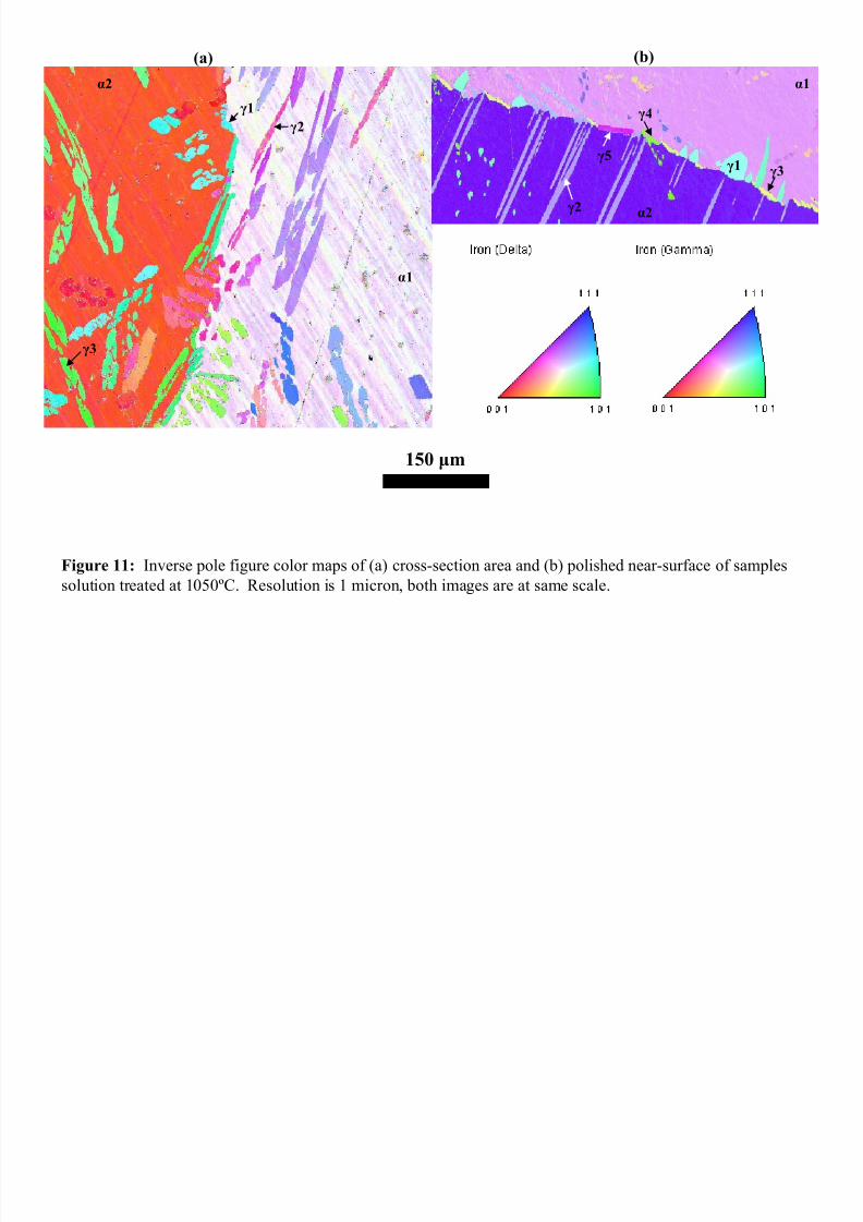
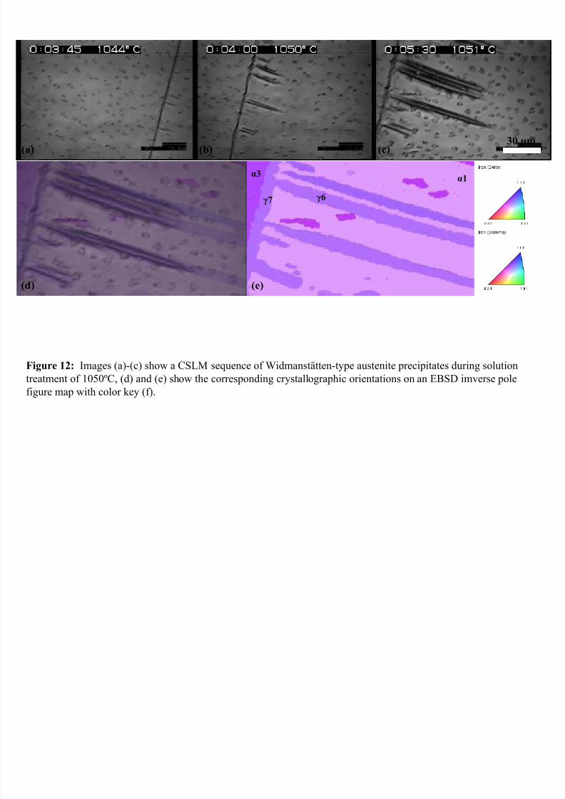
Figure 11 shows a pair of inverse pole figure color maps of polished (a) cross-sectionand (b) near-surface regions of 2 different samples that were transformed at 1050°C for
20 minutes and quenched. Figure 12(e) contains a different, smaller region of the samesurface as 11(b). Several austenite precipitates, and the ferrite grains in which they have
precipitated, have been labeled in these figures. Two distinct types of Widmanstätten
laths, indicated as γ2 and γ6 in the near surface images of 11(b)/12(e), are observed; primary (initiating directly from a grain boundary) and secondary (initiating from a
allotriomorph film at a grain boundary), respectively. Two types of allotriomorph-type
precipitates also appear; those similar to γ1, γ3, and γ4 which seem to evolve towards a
jagged sawtooth-like shape along a boundary, and those similar to γ5 and (especially) γ7which appear to form more of a film-like layer along a boundary with no jagged edges of
any kind. Similar precipitates appear cross-sectional image in 11(a), although it
becomes apparent that the lath-shaped precipitates are passing through the grains at awide variety of angles relative to the plane of polish, as indicated by a wide variation of
the apparent intragranular austenite between smallish ovals and long slender needles of
7/27/2019 A study of austenite precipitate growth in duplex stainless steel.pdf
http://slidepdf.com/reader/full/a-study-of-austenite-precipitate-growth-in-duplex-stainless-steelpdf 12/31
7/27/2019 A study of austenite precipitate growth in duplex stainless steel.pdf
http://slidepdf.com/reader/full/a-study-of-austenite-precipitate-growth-in-duplex-stainless-steelpdf 13/31
from repeated kinetic experiments under controlled conditions. A Focused Ion Beam
(FIB) milling process will likely be employed in tandem with the OIM in order to carry
out accurate serial sectioning of samples and determine the actual habit planes in a threedimensional structure. TEM analysis will provide more accurate crystallographic data,
and, more importantly, allow an atomic scale examination of the interface and thedislocation arrays surrounding it. These interface structures can then be compared
directly to kinetic and morphologic data to see if any correlations exist. Such correlations
would then be the basis for improving current models. Based on the multi-component
segregation observed in this alloy, and because complex diffusion fields exist whenever growth ledges are present, Thermo-Calc and DICTRA will be used to calculate the
composition and transport data needed for the models. In either case, these calculatedvalues will be compared to measured composition profiles to ensure accuracy.
References
1. H.I. Aaronson, H.A. Domian, and G.M. Pound: Trans. Met. Soc. AIME, 1966, Vol. 236, pp. 753-767
2. H.I. Aaronson, H.A. Domian, and G.M. Pound: Trans. Met. Soc. AIME, 1966, Vol. 236, pp. 768-781
3. G.J. Shiflet, J.R. Bradley, and H.I. Aaronson: Metallurgical Transactions A, 1978, Vol. 9A, No. 6, pp.
999-1008
4. G.R. Speich, A. Szirmae: Trans. Met. Soc. AIME, 1969, Vol. 245, pp. 1063-1069
5. C. Zener: Journal of Applied Physics,1949, 20, p. 950.
6. M. Hillert: Jernkontorets Ann., 1957, vol. 141, p. 757
7. R. Trivedi: Metallurgical Transactions A, 1970, Vol 1, No. 4, pp. 921 - 927
8. M. Hillert: Metallurgical Transactions A, 1975, Vol. 6A, No. 1, pp. 5-19
9. H.I. Aaronson, The Decomposition of Austenite by Diffusional Processes,(edited by V.F. Zackay and
H.I. Aaronson), pp. 387-546, Interscience, New York, 1962.
10. M. Enomoto: Acta Metallurgica, 1987, Vol. 35, No. 4, pp. 935-945
11. M. Enomoto: Acta Metallurgica, 1987, Vol. 35, No. 4, pp. 947-956
12. M. Enomoto, J.P. Hirth: Metallurgical and Materials Transactions A, 1996, Vol 27A, No. 6, pp. 1491-
1500
13. G. Spanos, R.A. Masumura, R.A. Vandermeer, and M Enomoto, Acta Metallurgica et Materiala, 1994,

7/27/2019 A study of austenite precipitate growth in duplex stainless steel.pdf
http://slidepdf.com/reader/full/a-study-of-austenite-precipitate-growth-in-duplex-stainless-steelpdf 14/31
16. G. Spanos and M. G. Hall: Metallurgical and Materials Transactions A, 1996, vol. 27A (6), pp. 1517-
1532.
17. M. V. Kral and G. Spanos: Acta Materialia, 2003, vol. 51 (2), pp. 301-311.
18. H. Yin, T. Emi, and H. Shibata: Acta Metallurgica., 1995, vol. 47, no. 5, pp 1523-1535.
19. R.J. Dippenaar, D.J. Phelan: Metallurgical and Materials Transactions A,2003, vol. 34B, no. 10, pp.495-501.
20. E. Schmidt, S. Sridhar, and Y. Wang: A study of Non-Isothermal Austenite Formation and
Decomposition in Fe-C-Mn Alloys. Metallurgical and Materials Transactions A. Mats Hillert SymposiumSpecial Issue (In Press).
21. E. Schmidt, S. Sridhar: Direct Observation of Austenite Formation and Decomposition in 4118 and
4320 Steels, Accepted for publication in the Proceedings of Solid-Solid Phase Transformations in
Inorganic Materials 2005, Phoenix, AZ, May 28 – June 3, 2005, ed. Jim Howe.
22. G. Spanos, M.G. Hall, Metallurgical and Materials Transactions A,1996, Vol. 27A, No. 6, pp. 1519-153.
23. T.J. Headley, J.A. Brooks: Metallurgical and Materials Transactions A,2002, Vol 33A, No. 1, pp. 5-15
24. D. A. Porter and K. E. Easterling: Phase Transformations in Metals and Alloys (second edition),
Stanley Thornes (Publishers) LTD., United Kingdom, 2000, pp. 143-148.
25. J.M. Howe, H.I. Aaronson, and J.P. Hirth: Acta Maeriala, 2000, Vol. 48, pp. 3977-3984.
26. J.W. Christian: Metallurgical and Materials Transactions A, 1994, Vol. 25A, No. 9, pp. 1821-1839.
27. G.C. Weatherly, W.Z. Zhang: Metallurgical and Materials Transactions A, 1994, Vol. 25A, No. 9, pp.1865-1874.
28. W. Z. Zhang, G.R. Purdy: Philosophical Magazine, 1993, Vol. 68, No. 2, pp. 291-303.
29. J.P. Hirth: Metallurgical and Materials Transactions A, 1994, Vol. 25A, No. 9, pp. 1885-1894.
30. W.Z. Zhang and G.R. Purdy: Philosophical Magazine, 1993, Vol. 68, No. 2, pp. 279-290.
31. U. Dahmen, Metallurgical and Materials Transactions A, 1994, Vol. 25A, No. 9, pp. 1857-1863.
32. H.I. Aaronson, The Decomposition of Austenite by Diffusional Processes,(edited by V.F. Zackay andH.I. Aaronson), pp. 387-546, Interscience, New York, 1962.
33. G.J. Shiflet and J.H. Van Der Merwe: Metallurgical and Materials Transactions A,1994, Vol. 25A,No. 9, pp. 1895-1903.
7/27/2019 A study of austenite precipitate growth in duplex stainless steel.pdf
http://slidepdf.com/reader/full/a-study-of-austenite-precipitate-growth-in-duplex-stainless-steelpdf 15/31

7/27/2019 A study of austenite precipitate growth in duplex stainless steel.pdf
http://slidepdf.com/reader/full/a-study-of-austenite-precipitate-growth-in-duplex-stainless-steelpdf 16/31
Table I: Composition (in wt%) of 2205 alloy used in this study, as well as the ASTM
composition range allowed for this alloy.
Cr Ni Mo Mn Si N C P S
2205(sample) 22.41 5.67 3.29 0.72 0.45 0.17 0.022 0.044 0.0004
2205(ASTM) 22-23 4.5-
6.5
3-
3.5
0.14-
0.20
0.030
Table II: Average composition of austenite precipitates and parent ferrite grain after CSLM experiment, obtained by SEM/EDX QuantMap analysis.
Iron Chromium Nickel Molybdenum Silicon
γ lath 68.67 20.24 7.90 2.58 0.63
γ allotriomorph 69.66 20.27 7.95 1.77 0.36
α parent 66.55 24.57 4.73 3.54 0.60
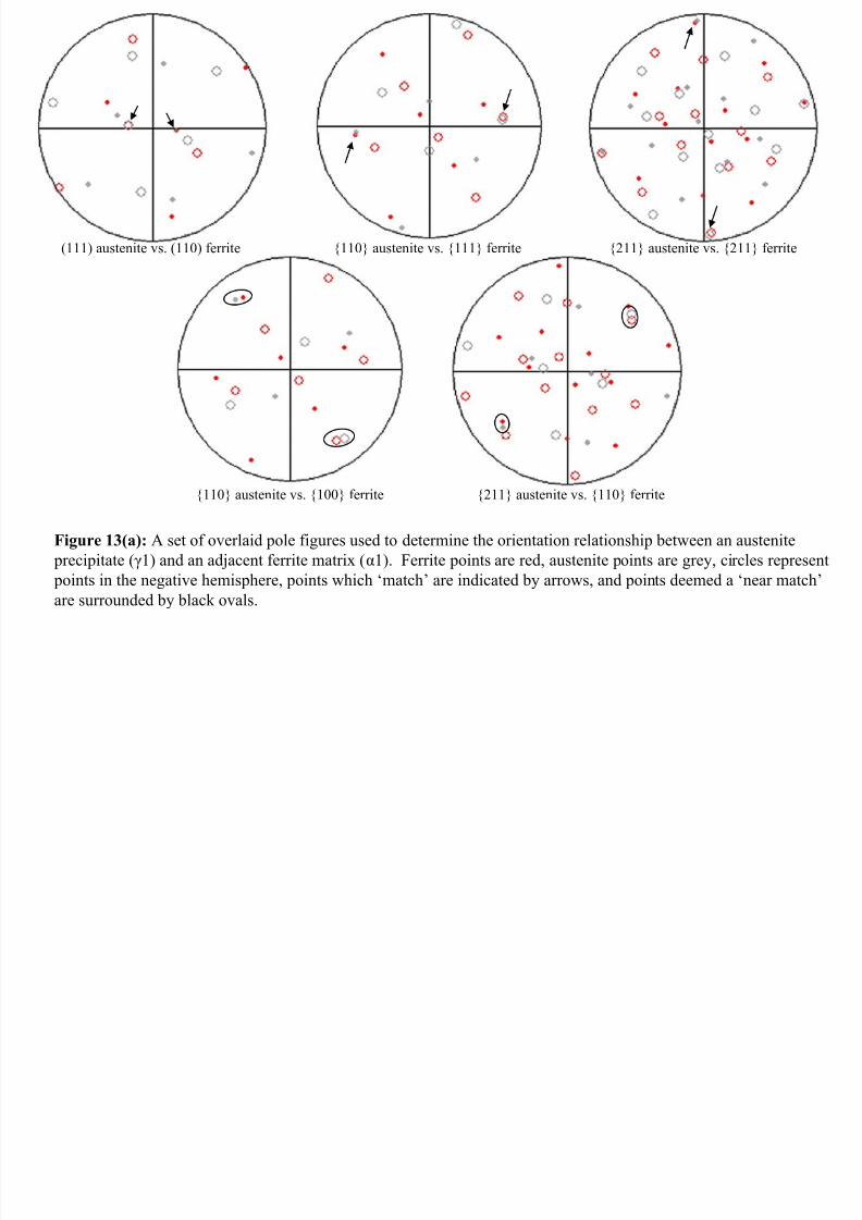
Table III(a): Apparent orientation relationship between selected austenite precipitateswith selected ferrite grains on polished near-surface shown in Figures 11(b) and 12(e)
γ1 γ2 γ3 γ4 γ5 γ6 γ7
α1 K-S Pitsch K-S none K-S near N-W near N-W
α2 none - - - - K-S K-S, near N-Wα3 - K-S none K-S none - none
Table III(b): Apparent orientation relationship between selected austenite precipitates
with selected ferrite grains on polished cross-section shown in Figure 11(a).
γ1 γ2 γ3
α1 None K-S none
α2 K-S none K-S

7/27/2019 A study of austenite precipitate growth in duplex stainless steel.pdf
http://slidepdf.com/reader/full/a-study-of-austenite-precipitate-growth-in-duplex-stainless-steelpdf 17/31
[110] FCC
[111] BCC
[112] FCC
[112] BCC
Figure 1(a): Overlay of (111) FCC surface (red, white, and pink circles represent atoms in the plane,
0.577*a above the plane, and 1.155*a above the plane, respectively) with a (110) BCC surface (black and grey circles represent atoms in the plane and .707*a above the plane) in the K-S configuration.

7/27/2019 A study of austenite precipitate growth in duplex stainless steel.pdf
http://slidepdf.com/reader/full/a-study-of-austenite-precipitate-growth-in-duplex-stainless-steelpdf 18/31
7/27/2019 A study of austenite precipitate growth in duplex stainless steel.pdf
http://slidepdf.com/reader/full/a-study-of-austenite-precipitate-growth-in-duplex-stainless-steelpdf 19/31
(a) (b)
Figure 2: Selected simplified phase fraction diagrams for 2205 duplex stainless steel; in (a)
trace amounts of phosphorous, sulfur, and carbon are ignored, while in (b) all phases exceptferrite and austenite have been suspended.

7/27/2019 A study of austenite precipitate growth in duplex stainless steel.pdf
http://slidepdf.com/reader/full/a-study-of-austenite-precipitate-growth-in-duplex-stainless-steelpdf 20/31
7/27/2019 A study of austenite precipitate growth in duplex stainless steel.pdf
http://slidepdf.com/reader/full/a-study-of-austenite-precipitate-growth-in-duplex-stainless-steelpdf 21/31
7/27/2019 A study of austenite precipitate growth in duplex stainless steel.pdf
http://slidepdf.com/reader/full/a-study-of-austenite-precipitate-growth-in-duplex-stainless-steelpdf 22/31

7/27/2019 A study of austenite precipitate growth in duplex stainless steel.pdf
http://slidepdf.com/reader/full/a-study-of-austenite-precipitate-growth-in-duplex-stainless-steelpdf 23/31
30 µm
(b)
(c)
(a)
(d)
Figure 6: Series of CSLM images (a)-(d) show directionally-oriented precipitation of non-metallic precipitateson the surface of a sample during cooling to a solution annealing temperature
7/27/2019 A study of austenite precipitate growth in duplex stainless steel.pdf
http://slidepdf.com/reader/full/a-study-of-austenite-precipitate-growth-in-duplex-stainless-steelpdf 24/31
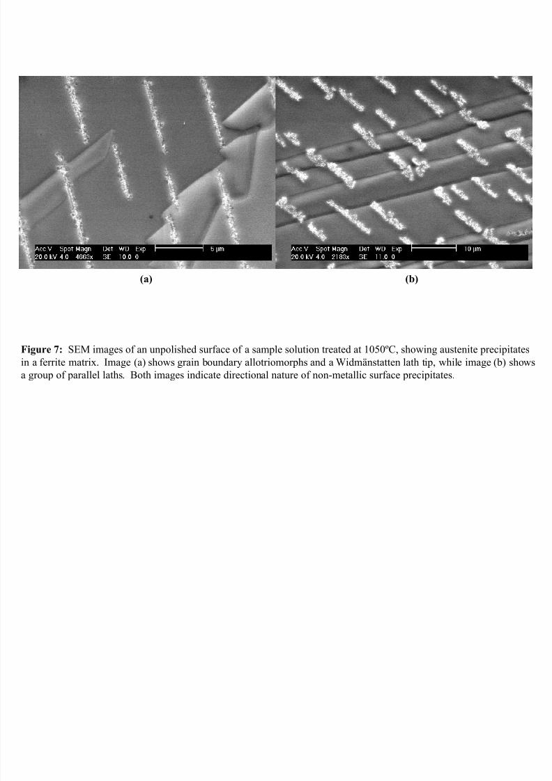
(a) (b)
Figure 7: SEM images of an unpolished surface of a sample solution treated at 1050ºC, showing austenite precipitates
in a ferrite matrix. Image (a) shows grain boundary allotriomorphs and a Widmänstatten lath tip, while image (b) showsa group of parallel laths. Both images indicate directional nature of non-metallic surface precipitates.

7/27/2019 A study of austenite precipitate growth in duplex stainless steel.pdf
http://slidepdf.com/reader/full/a-study-of-austenite-precipitate-growth-in-duplex-stainless-steelpdf 25/31
30 µm
(b)
(c)
(a)
(d)
Figure 8: CSLM still images showing (a) - (b) austenite allotriomorphs and (c) - (d) Widmänstatten type
austenite laths precipitating at δ-ferrite grain boundaries.

7/27/2019 A study of austenite precipitate growth in duplex stainless steel.pdf
http://slidepdf.com/reader/full/a-study-of-austenite-precipitate-growth-in-duplex-stainless-steelpdf 26/31
0
20
40
60
80
100
0 20 40 60 80 100 120 140
Lath 1, 1050C
Lath 2, 1050C
Lath 3, 1050C
Lath 4, 900C
Lath 5, 900C
Allotriomorph 1, 1050C
Allotriomorph 2, 1050C
S i z e o f G r o
w i n g A u s t e n i t e P r e c i p i t a t e ,
δ ( µ m
)
Elapsed Time of Transformation, t(sec)
Figure 9: Growth kinetics of austenite precipitate laths and allotriomorphs at 1050ºC and laths at 900ºC.

7/27/2019 A study of austenite precipitate growth in duplex stainless steel.pdf
http://slidepdf.com/reader/full/a-study-of-austenite-precipitate-growth-in-duplex-stainless-steelpdf 27/31
7/27/2019 A study of austenite precipitate growth in duplex stainless steel.pdf
http://slidepdf.com/reader/full/a-study-of-austenite-precipitate-growth-in-duplex-stainless-steelpdf 28/31
7/27/2019 A study of austenite precipitate growth in duplex stainless steel.pdf
http://slidepdf.com/reader/full/a-study-of-austenite-precipitate-growth-in-duplex-stainless-steelpdf 29/31
7/27/2019 A study of austenite precipitate growth in duplex stainless steel.pdf
http://slidepdf.com/reader/full/a-study-of-austenite-precipitate-growth-in-duplex-stainless-steelpdf 30/31

7/27/2019 A study of austenite precipitate growth in duplex stainless steel.pdf
http://slidepdf.com/reader/full/a-study-of-austenite-precipitate-growth-in-duplex-stainless-steelpdf 31/31
100 austenite vs. 110 ferrite111 austenite vs. 110 ferrite
Figure 13(b): A set of overlaid pole figures showing no rational orientation relationship between an austenite
precipitate (γ1) and a second adjacent ferrite matrix (α2). Ferrite points are red, austenite points are grey, and
circles represent points in the negative hemisphere. No matches or near matches exist.