a standard technique used when analyzing vibrating … · student groups to the analysis of...
TRANSCRIPT

Real-Time Holography
. . *David A. Johnson, David B. Parker, Mark L. Lott
GMI Engineering and Management InstituteDepartment of Science and Mathematics
1700 West Third Ave.Flint, Michigan 48504
Jjget Sound Naval Ship YardPlanning Department, Code 170.11
Bremerton, Washington 98314
ABSTRACT
As part of our coherent optics course for senior level undergraduates, our students complete a laboratory inwhich they are trained in laser safety and set up a complete holographic system. The students perform all phases ofthe setup from aligning pinholes for spatial filters to ensuring the correct illumination levels for plate exposure. Thestudents are then required to investigate some aspect of holography. The topic may be of their own choosing or canbe selected from a list a topics provided by the instructor. In this paper we will describe the contribution of variousstudent groups to the analysis of vibrating objects with or without static deformation using real-time holography.Three years ago we started this project by asking two very simple questions; first, "why are there twice as manyfringes in time-average holographyT'; and second, "can the fringe contrast for real-time holography be enhanced?" Inthe course of this research, we "discovered" quite a few things which were already well known, and a few things thatare not. But in the course of this work, all of the authors, faculty and students, enhanced our understanding ofholography and its applications.
Keywords: Real-Time, Time-Average, Holography, Phase Stepping, Vibration, Education
2. INTRODUCTION
GMI Engineering and Management Institute (GMI-EMI) is a fully accredited, private college offeringBachelors Degree Programs in Electrical Engineering, Industrial Engineering, Mechanical Engineering, ManufacturingSystems Engineering, Management, Applied Physics, Computer Engineering, Environmental Chemistry and AppliedMathematics. Approximately 2500 undergraduates are enrolled in a five year program ofalternating 12 week periodsof classroom studies and paid work experiences at one of over 500 corporate affiliates. Minors are offered in severalareas including Applied Optics.
Coherent Optics and the accompanying laboratory introduce students to laser applications including laserscanners, alignment techniques, optical triangulation, interferometry, heterodyning, holography, holographicinterferometry, Fourier optics, optical data processing, speckle photography and speckle interferometry. In thelaboratory, the students receive instruction in laser safety, radiation measurements, holography and Fourier optics.The students have access to two optical tables, a 50mW Helium Neon laser, an Argon laser, Newport thermoplasticholographic camera, computer vision system, and a wide vari.ety of optical components. A sketch of the holographicsystem is shown in figure 1. Thermoplastic plates are used as the recording media. Thermoplastic plates have anumber ofadvantages over photographic plates for real-time holographic interferometry. The plates can be developedin situ quickly, and bias fringes due to expansion or shrinking of the emulsion are not present. The students areresponsible for all aspects of their project including experimental design and setup, data acquisition, data analysis, andreporting. Each student team is required to submit a formal report and to deliver a 15 minute presentation to whichall interested faculty and students are invited to attend.
3. HOLOGRAPHIC INTERFEROMETRY
A standard technique used when analyzing vibrating objects is to first use real-time holographicinterferometry to determine a resonant frequency of an object. This technique produces low contrast fringes which aredifficult to observe. The contrast of these fringes will usually change with time due to instability in the holographic
O-8194-1884-6/95/$6.oo SPIE Vol. 2525 / 433
system and/or static object deformation. To obtain high contrast fringes once a resonance has been located, a time-average hologram is produced. If this two step process is repeated for each resonant frequency of an object, it can bevery time consuming.
On a thermoplastic plate the interference pattern is recorded as thickness variations. That is, a phasehologram is produced. The complex amplitude vectors of the object and reference beams are U0 and UR, respectively.All beams are polarized in the vertical direction. When played back with the reference beam, the complex amplitudeU3 of the light producing the holographic image being observed is
U3 -jCU0 (1)
The multiplicative constant C is proportional to the irradiance of the reference beam and -j represents a -ir/2 phaseshift of U3 relative to U01•
3.1 Time-Average Holography
Using equation (1) and assuming C=l, the irradiance I of the play back light for a phase hologram used fordouble exposure holographic interferometry can be shown to be
I = 410cos2(AO/2) (2)
where zO is the phase shift between exposures and I is the irradiance of the object beam. Figure 2 is a sketch of theholographic system geometry and its coordinate system. A phase shift due to object deformation can be found byusing
e = k•M (3)
where M is the displacement vector of point P on the object and zk is the sensitivity vector2. The sensitivityvector L\k is equal to the propagation constant vector difference (lq - k2). The propagation constant vectors k1 andk2 represent the light illuminating point P on the object and light scattered to point Q on the hologram. Theplayback light due to a hologram used for time-average holographic interferometry can be shown to be
I = 10J02(a) (4)
where J0(a) is a Bessel function of the first kind of the first order. The function J02(a) varies between zero and somemaximum ensuring excellent fringe contrast. For a point on the object vibrating with simple harmonic motion in adirection parallel to the z axis
(5)
whereA is the vibrational amplitude.
3.2 Real-Time Holography
The equations necessary to evaluate vibrating objects with real-time holographic interferometry can also bederived starting from equation (1). Setting C=l, the complex amplitude vector representing the holographic image is
U3 =-j 'i R U0 eJ13, (6)
and the complex amplitude vector representing the object beam is
= R u0 j( + w) (7)
434 / SPIE Vol. 2525

The phase shifts i, Lip , and are due to object vibration, static deformation of the object, and phase variationsintroduced in the reference beam, respectively. The ratio of the object beam to playback beam complex amplitudes isR. The resultant complex amplitude vector due to the interfering object and playback is
U= 'i U0 [ jeJLIl3 R ei(M + p)] (8)
The irradiance I of the light can be shown to be
I=I{1 +R2-2Rsin(A+A -z43)='0 [ R2 -2R sin(&p — ) cos(4) - 2R cos(AW -A13) sin(i)}. (9)
For integration times which are long compared to the vibrational period of the object under test,
<cos(A)> = J0(a), and <sin(L4)> = 0. (10)
Yielding,
I = I [ 1 + R2 - 2R sin(Atp — 3) J0(a)j. (11)
Fringes described by this equation have maximum contrast if sin(p - A3) = and R=1. Two problemsexist. One is that tp, the phase shift due to static deformation, is not constant for the entire image. That is staticdeformation fringes are present which interfere with the fringes due to vibration. The contrast can also drift due tothermal variations which alter the reference phase . A second problem is that even if sin(ip — Afi) = thefringe contrast is still low when compared to time-average holograms due to the DC bias term (1 +R2).
4. STUDENT RESEARCH4.1 Introduction
In this section the student's contribution to our understanding of real-time holography will be discussed. inthe 1991 Fall semester, Ed Barshaw and Ben Lewis were able to design an experiment in which they used real-timeholography to measure the vibrational amplitude of a circular diaphragm vibrating in its fundamental mode. Theirwork verified existing theoretical development, and established the basic groundwork for future investigations.
4.2 Fringe Doubling
In the 1992 Fall semester, Pat Auth, Quinten Geyer, and Cindy Newmeyer investigated the fringe doublingseen in time-average holography. With some guidance, they hypothesized that the fringe doubling occurs since intime-average holography the object spends most of its time maximally displaced from equilibrium. Therefore, thepeak to peak displacement is being measured. On the other hand, in real-time holography, the first exposure of thehologram is taken with the object at rest. When the object is vibrating it again spends most of its time displacedmaximally toward or away from the hologram. However, since real-time holography records the magnitude of thedisplacement and not the direction, the displacement is recorded with respect to the equilibrium position -exactlyhalf of the peak to peak displacement. This is illustrated in figure 3.
To test this hypothesis, the students first obtained a real-time hologram of a circular diaphragm vibrating inits fundamental mode. They used the computer vision system to store and display this image, switched off thevibration, and then they used a micrometer to displace the center of the diaphragm until the number of fringesobserved was exactly the same as the number seen when the diaphragm was vibrating. In effect, they forced a staticdisplacement equal to the maximum displacement of the vibrating diaphragm. They then erased the hologram,exposed it again, backed the micrometer off, and reestablished fundamental mode resonance. The number ofinterference fringes observed in the resulting real-time hologram was exactly twice the number originally observedsince the total peak to peak displacement was now being recorded.
SP!E Vol. 2525 /435

4.3 Physical Contrast Enhancement
Equation (1 1) shows that the interference fringe contrast in a real-time hologram will vary from zero tosome maximum value as the difference between the reference and object beam path lengths change. Therefore, thecontrast in real-time holograms can drift due to thermal instabilities in the optical set-up. In his undergraduatethesis, Mark Lott interfaced a home-built, piezoelectric mirror placed in the reference beam path, to a high voltageamplifier and digital to analog converter. Using a computer vision system, he then designed a control algorithmwhich changed the mirror position to keep a user specified, stationary area on the object light or dark, thereby forcingmaximum interference fringe contrast. He was able to demonstrate that the system efficiently removed much theinstability initially present.
hi the 1994 Summer semester, Jason Butler and Rob DeWys investigated a variety of ways in which theinterference fringe contrast in real-time holography could be further enhanced. They investigated the use ofpolarizers, object to reference beam intensity ratios during exposure and playback, the effect of varying coherencelength, and the effect ofremoving stray reflections from background objects. They found that polarizers and a darkbackground behind the object improved the interference fringe contrast slightly. They found that as long as thedifference between the object and reference beam path lengths was within the coherence length of the laser used, pathlength variations had little effect other than those discussed in the previous section. They also found that theoptimum object to reference beam intensity ratio was 1 1: 1 on exposure and 1: 1 on playback.
4.4 Software Contrast Enhancement
In the Fall of 1994 semester John Sundeen and Matt Wavra investigated two phase stepping techniques3'4.The first is applicable if static deformation is not present. In this technique a real-time image is storedelectronically, the piezoelectric mirror in the reference beam is used to introduce a 1800 shift, and then a secondimage is stored. The two images are then subtracted to yield an enhanced image.Starting from equation (1 1), if the piezoelectric mirror in the reference beam path is adjusted so that a stationaryregion on the object is bright then sin(ip - A3) = -1 and if the stationary region is dark then sin(iip — i}) = +1.Taking the difference ofthe two stored images yields
Iii - 121 = 4RJIJ0(a)t, (12)
thereby removing the DC bias term in equation (1 1) and greatly improving fringe contrast. Figure 4a shows a real-time hologram for the circular diaphragm vibrating in its fundamental mode, and figure 4b shows the enhancementobtained by this image subtraction technique. Vibrational fringes are enhanced; however, a static deformation fringedoes obscure these fringes on the right hand side of the image.
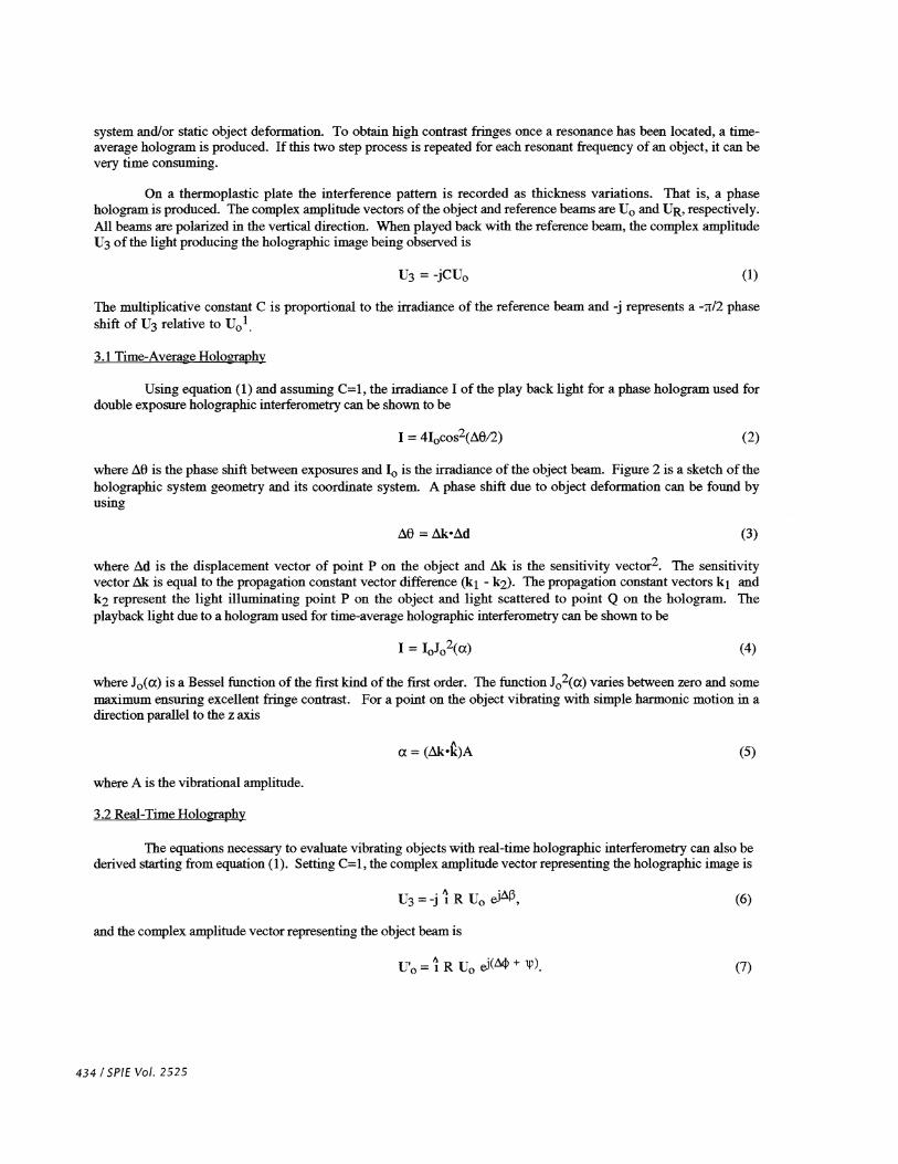
The second technique enhances the interference fringe contrast and allows the effects ofstatic and vibrationaldeformation on an object to be separately resolved and analyzed5. In this technique, four separate images are stored atphase shifts of 0 , 90 , 180 , and 270 . The phase shifts can be accurately generated by carefully calibrating thepiezoelectric mirror, and by monitoring the average intensity of a static point on the object. The data in theseimages were processed to generate Fourier coefficients a, al, and b1 which were then used to produce two separateimages. Specifically, for phase holograms
a0 = I= IL( 1 + R2), ai = I cos(zf3) = -2RJ10J sin(ip) J0(a),i=1 i=1
and b1 = I sin(i131) = -2R1101 cos(p) J0(a) (13)i=1
where Afij = . As indicated above, we used N=4. The enhanced fringe pattern can be obtained using the
following:
436 / SPIE Vol. 2525

'/ a12 + b12 2RI'(x,y) =
a0= J0(a)J R2 (14)
This technique eliminates fringes due to static deformation. The contrast term 2R1( 1 +R2) has a maximum valuewhen R = 1. The phase shift Aip due to static deformation can be obtained using
LMp=tan1 . (15)
One of these images contains fringes which are related entirely to the vibrational displacement of the object,and the other image contains fringes which are related to the static displacement of the object. Figure 5a shows areal time hologram of the vibrating diaphragm which had been purposefully tilted in at the top to introduce a largestatic deformation. Notice that the combination of static and vibrational interference fringes is very difficult toresolve. Figure Sb shows the processed image corresponding to vibrational displacement, and figure Sc shows theprocessed image corresponding to the static deformation. Note that the effect of static deformation is separated outand high contrast fringes result which can be easily analyzed to extract topological information.
S. CONCLUSION
GMI-EMI students taking the Applied Optics minor have been involved in an on-going investigation ofreal-time holography. Each student group has contributed to the advancement of this research, and each group hasbeen exposed to the challenges of experimental design and the intricacies of an advanced optical system. Byinvolving undergraduates in this research, their educational experience has been enhanced, the research progressed (ifslowly) in an institute primarily known for undergraduate education, the faculty and students progressed along a pathof learning, and excellent results were obtained.
6. ACKNOWLEDGMENTS
The authors would like to thank Newport Corporation for their generous equipment donation. A specialthanks to GMJ students Pat Auth, Ed Barshaw, Jason Butler, Rob DeWys, Quinten Geyer, Ben Lewis, CindyNewmeyer, John Sundeen and Matt Wavra whose laboratory research projects are the focus of this paper.
7. REFERENCES
1. J. T. Luxon and D. E. Parker, Industrial Lasers and TheirApplications, Prentice Hall Inc., NJ, 1992.
2. C. M. Vest, Holographic Interferometry, John Wiley & Sons, Inc. New York (1979).
3. K. Creath, "Phase-Measurement Interferometry Techniques," Chapter V in Progress in Optics XXVI, E. Wolf ed.,pp 350-393, Elsevier Science Publishers B. V., 1988.
4. K. Creath, "Phase-Measurement Techniques for Nondestructive Testing," Proc. 1990 Society of ExperimentalMechanics Fall Conf, 473-479, 1990.
S. S. Nakadate, "Vibration Measurement using Phase-shifted Time-average Holographic Interferometry," AppliedOptics, vol. 25, no. 22, 4155-416 1. 1986.
SPIE Vol. 2525/437

438 / SPIE Vol. 2525
8. FIGURES
Thermoplastic plate
Vidicon camera
Figure 1. Holography System
z
Diaphragm
0Hologram Object beam
point source
Figure 2. Geometry and Coordiante System
y

Figure 3. Recorded Diaphragm Displacement a) Time Average Holography b) Real Time Holography
Figure 4. Image Subtraction Technique a) Original Hologram b) Enhanced Hologram
SPIE Vol. 2525 / 439
0 ExtremePositions
r 2A\ /'I0(a)
Time average
ExtremePositions
I \___I I'I
Holographicimage
(b)
Real time
(a) (b)
I
_(a)
440 / SPIE Vol. 2525
Figure 5. Phase Stepping Technique a) Real-time Hologram b) Vibrational Fringes c) Static Deformation Fringes.