a simple & portable equipment for water permeability test of concrete
TRANSCRIPT

A SIMPLE & PORTABLE EQUIPMENT FOR WATER
PERMEABILITY TEST OF CONCRETE Hemant Kumar Bhagoria,
I.R.S.E.
Sr Divisional Engineer (Special),
South Central Railway,
Vijayawada, ( A.P.)
Introduction:
All over Indian Railway lot of construction work going on involving RCC and
PSC construction of major and important bridges and other important concrete structures.
This requires quality control at various stages of casting of the concrete and than testing the
various components for compressive strength and permeability etc at certain intervals.
Now-a-days there is great emphasis on the durability of the concrete as lot of concrete
structure started deteriorating even before their designed life. As permeability being the
main factor which affects the concrete durability and determines the life of the concrete
structure. A durable concrete structure should invariably be sound and should have
minimum water penetration under the extreme environmental conditions for which it is
designed. There are various ways in which in which permeability test is carried out e.g.
chloride ion penetration test, air permeability and water penetration test. The last is the
criteria for railway works.
The equipment has been developed independently by the author is portable, simple,
easy to use by the field staff. The author has conducted nos. of tests by using this equipment
for Guntakal-Hospet doubling project ( 115 Km) South Central Railway and also the
equipment has been supplied to the Dy Chief Engineer of other construction divisions of
South Central Railway and is being used extensively by them for permeability test. The
paper deals with the concrete water permeability and durability of concrete and the factors
that affects both.
1.0 Objective for developing -the equipment:
The objective for the development was to design, fabricate and demonstrate, a simple,
easy to use, effective and economic water permeability test equipment conforming the
guidelines provided by the Railways.
It is based on simple principal of keeping water under air pressure in a confined
pressure chamber. Due to different densities of water and air the water will always be under
air as it is heavier, ( this is best explained by filling a transparent balloon partially with
water and air). The water pressure is applied on the concrete specimen in most effective
way to find the water penetration in the concrete specimen. The highlight of the equipment
is that the concrete specimen is always available for visual inspection during all the 96 hrs
of pressure application. The concept may look somewhat odd at first glance, but it path
breaking and it works and works well!
1.1 Approach for developing the equipment:
When the author was posted as Executive Engineer (Const), for Guntakal-Hospet
doubling (115Km), it is found that in all the approved major & important bridge drawings
(GAD) the permeability test made mandatory and no institute available nearby to conduct

PERMEABILITY TEST EQUIPMENT
- 2 -
the test as per DIN-1048 standards including the JNTU, Hydrabad, local Vijay Nagar
Engineering College(ISO-9000) and IISc, Banglore. While the CRS/ Southe Central Circle,
Secundrabad insisting on the permeability test during his inspection of Gudur-Renugunta
doubling inspection. Then the author searched for the literature from every available source
including the internet, but not even a single reference found for portable, handy equipment
for water permeability test of concrete as per DIN-1048 requirements. They are mainly
related to air permeability, chloride ion permeability, and some reference for water
permeability based on the amount of water penetration during a given time interval i.e. rate
of water penetration. However this kind of test does not give the correct picture as
explained later in the paper. In fact it is better to say that everybody talks of permeability/
durability of concrete and its importance but no body tells how to do the test and where to
get the test done regularly? Mostly methods/equipments were designed for the air and
chloride penetration and none as per the guidelines of DIN 1048 Part I. So the author
started with one page literature available in the Report no. BS-14(Revised) Jan-2001 (a
RDSO publication) and appendix ‘C’ of Clause 5.4.1.1 of IRS Concrete Bridge Code.
1.2 Current Practices & Reason for developing the equipment:
Currently the permeability test as per ASTM standards (not as per DIN 1048 standards),
is being done by a very few technical institutes, which charges a very high amount for
conducting this test which does not confirm to Railways requirement. Because of this very
few tests for permeability are being done in practice. Also most of the field construction
units, which are executing huge quantities of the concrete, are not able to perform this test.
Even the Zonal Railways material testing labs are not conducting this test due to non-
availability of the simplified equipment and procedure. This is resulting in majority
RCC/PSC concrete components are not being tested for permeability, despite being
mandatory? What a paradox?
The author then design a simplified equipment, and after about seven months work, the
equipment was conceptualized, designed and developed, which has been greatly
appreciated by the CAO/C, S.C. Railway and other CE’s/Construction, and other Dy CE’s
of other units. The same was published in the Hindi magazine “Nirman Darpan” of South
Central Railway in 2004.
1.3 Criteria for Permeability test as per Railway Guidelines:
As per “IRS Concrete Bridge Code” and “Durability of Concrete Structure-
Report no. BS-14(Revised) Jan-2001” (a RDSO publication), the average penetration of
water should not be more than 25 mm on breaking the specimen after the test. The test is
mandatory for all RCC & PSC components of all Major and Important bridges, while it is
desirable for minor bridges and is equally applicable for other concrete structures like water
tanks, buildings, washing aprons etc.

PERMEABILITY TEST EQUIPMENT
- 3 -
1.4 Frequency of testing:
The frequency of test/tests to be done for various RCC/PSC components is not exactly
defined neither in IRS concrete bridge code/ Durability of Concrete Structure-Report no.
BS-14(Revised) Jan-2001 nor in IS -456, 2000. It is given for concrete cube strength which
is based on the quantity of concrete work done. However the author is of the opinion that
the water permeability test should be conducted for all major concrete components like PSC
girder, deck slab, RCC bed block, RCC slab of concrete bridges and other important
structure like water tank etc. Also the Engineer-in-charge of the project can decide the
frequency of test under his juriddiction.
1.5 Equipment as per IRS concrete Bridge code Appendix-C, as per clause 5.4.1.1:
This equipment described in the IRS concrete bridge code is mainly consist of a very
complex arrangements and with this set of arrangements it very-very difficult to
conduct the test by any field staff as shown below in fig 1. The application of pressure
by using hand pump of 7-bar pressure is very difficult to achieve unless some
reciprocating pump is provided. This may be the reason of not doing this test frequently.
Also the equipment does not have the portability.
Fig-1
2.0. Details of the Permeability Test Equipment:
It equipment developed consists of the mainly three parts:
a. Lower part consists of MS plate of 10 mm
thick of diameter 260mm having 12 mm
diameter eight holes at equal distance which
are required for holding the concrete specimen
as shown in figure-2.
b. The middle part consists of two circular MS
plate of 10mm thickness, 260mm wide and
having a 100mm dia hole at centre over which
a GI pipe of internal dia 100mm and of
150mm height is welded with another MS
plate of 6mm thickness at top having 6 holes, Fig-2
TOP PART
PERMEABILITY TEST EQUIPMENT
- 4 -
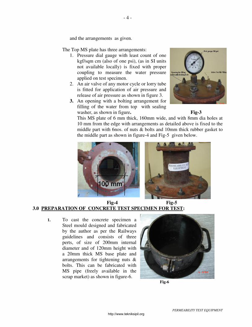
and the arrangements as given.
The Top MS plate has three arrangements:
1. Pressure dial gauge with least count of one
kgf/sqm cm (also of one psi), (as in SI units
not available locally) is fixed with proper
coupling to measure the water pressure
applied on test specimen.
2. An air valve of any motor cycle or lorry tube
is fitted for application of air pressure and
release of air pressure as shown in figure 3.
3. An opening with a bolting arrangement for
filling of the water from top with sealing
washer, as shown in figure. Fig-3
This MS plate of 6 mm thick, 160mm wide, and with 8mm dia holes at
10 mm from the edge with arrangements as detailed above is fixed to the
middle part with 6nos. of nuts & bolts and 10mm thick rubber gasket to
the middle part as shown in figure-4 and Fig-5 given below.
Fig-4 Fig-5
3.0 PREPARATION OF CONCRETE TEST SPECIMEN FOR TEST:
1. To cast the concrete specimen a
Steel mould designed and fabricated
by the author as per the Railways
guidelines and consists of three
perts, of size of 200mm internal
diameter and of 120mm height with
a 20mm thick MS base plate and
arrangements for tightening nuts &
bolts. This can be fabricated with
MS pipe (freely available in the
scrap market) as shown in figure-6. Fig-6
http://www.tekniksipil.org

PERMEABILITY TEST EQUIPMENT
- 5 -
2. Seal all the joints of the mould with neat cement paste or with any other sealing
material and apply the lubricant all round the mould surface inside, similar to
cube casting.
3. Pour the concrete in the mould and make the test specimen similar to the cube
making and vibrate the mould with concrete so that uniform compaction is
achieved. This is very important as this will give uniformly compacted concrete.
4. Remove the test specimen from the mould next day
after 24 hours of casting and immerse in water for
curing for 28 days as shown in figure-7 below.
( As per IRS bridge code appendix ’C’ , the central
100mm diameter circular area on the side on which
water pressure is to be applied is to be roughened
with wire brush and to be sealed with two coats of
cement water past, preferably with same W/C ration
as that of mix), However this is not required as this
will not give actual concrete surface for
permeability test, as has been done and observed by
the tests done by the author. Fig-7
4.0 PROCEDURE FOR DOING THE PERMEABILITY TEST:
Following pressure are to be applied as per IRS concrete bridge code
( Clause 5.4.1.1,Appendix-G , page 84):
1 bar pressure for 48 hours (equivalent to1.0197 kg(f)/cm2 and 14.50378 psi)
3 bar pressure for 24 hours (equivalent to3.0591 kg(f)/cm2 and 43.51134 psi)
7 bar pressure for 24 hours (equivalent to 7.1379 kg(f)/cm2 and 101.5262 psi)
(Total 96 hours required to perform the test).
PROCEDURE
1. Take out the concrete test specimen after 28 days
of curing and clean it with cotton cloth and place
it on the lower MS plate of the equipment, below
the test specimen put one rubber sheet of good
quality (even one robber pad can be kept), this
will ensure uniform compression of the specimen
even if the test specimen surface is not even due
to engraved details of the test specimen (e.g.
concrete component, date of concrete, grade etc)
marking at top, as shown in the figure-8. Fig-8
2. Put the rubber gasket ( similar to gasket used for
coupling of the water pressure pipes) of good quality
of approximately 10mm thick having 100mm dia
opening at centre over the test specimen, as shown in
the fig-9.

PERMEABILITY TEST EQUIPMENT
- 6 -
3. Put the middle arrangement fixed with the top arrangements, over this and fully
tighten all the nuts and bolts uniformly so that the rubber gasket and the test.
Specimen will be subjected to uniform pressure and will seal the around except
central 100mm dia opening, as shown in the Fig-9.
4. From the top hole fill the clean water (app.200ml) and tighten with the water sealing
nut fully, as shown in the figure-10.
5. Apply the 1 bar of air pressure through foot pump or any other arrangements and
check for any leakage of pressure (this can be done by observing the pressure gauge
reading or even by putting the complete set under water. If all the nuts & bolts are
tightened fully & properly, no leakage of either water or air will be observed, as
shown in the figure below. ( View videos taken during trial stage).
6. Leave the equipment for
48 hrs. As the water is
heavier than air, the water
will remain fully in
contact over 100 mm
diameter opening area of
the test specimen with the
applied pressure, as
shown by the pressure
gauge.
Fig-10
7. After expiry of 48 hours of one bar pressure, apply 3 bar pressure and again check
for any leakage and leave for next 24 hours.
Fig-11 Fig-12
8. After expiry of 72 hours, apply 7 bar pressure. This pressure is very high and may
be difficult to apply through foot pump or hand pump. The test equipment can be
taken to any auto puncture air filling shop and by using air compressor, a pressure

PERMEABILITY TEST EQUIPMENT
- 7 -
of 7-bar can be applied, as shown in fig 5, ( the equipment developed has been
subjected to even up to 8 bar (>125 psi) and tested in by submerging in water for
any leakage of pressure and no leakage was observed as shown in figure 11 and 12
above.
9. After expiry of 96 hours, release the pressure though the valve provided at top and
release the water by loosening the water inlet/outlet bolt.
5.0 Observations During the application of water Pressure
1. While applying the first one bar pressure, observe for any leakage of water, as this
may result in the loss of pressure. If any drop in pressure observed retighten all the
nuts and bolts. It is better to tight all the nuts and bolts fully before applying
pressure.
2. During the pressure application, (particularly
7-bar), observe the water penetration on the
sides of the specimen. It can be seen as
moist/wet spots on the outer circular surface,
if the concrete is not fully compacted or not
properly cured. Also moist spots are observed
when the aggregates used for the concrete are
having some soft stones as shown in Fig 13. If
this happens examine the cause of poor
concrete on breaking the specimen in parts
and take corrective action, educate the field
staff of reasons and remedial measures.
Fig-13
6.0 Testing of the Concrete Test specimen for water penetration for Permeability:
1. Un-tighten the lower part’s nuts and bolts
and remove the test specimen for
breaking in two halves to know the water
penetration.
2. Put the Specimen with the non-water
pressure face upward in the Concrete
Cube testing machine (Fig.14) over two
round or square bar pieces approximately
120mm apart at the bottom MS plate of
the machine and one at centre on top of
the test specimen ( fig 15) pointed with red Fig-14
colours. This will ensure breaking of specimen in two parts. (Care to be taken that
the side after test specimen exposed to water pressure should face downward).

PERMEABILITY TEST EQUIPMENT
- 8 -
3. Tight the upper jaw and apply pressure
slowly/gradually either with hand operated
compression testing machine or electrically
operated hydraulic machine, the specimen will
break at middle in two parts at center as shown in
fig- 15.
4. Observe the penetration on two parts on water
pressure facing side, measure the penetration with
scale or vernier caliper as shown in fig -16 with red
line marking. For cube shown in Fig-16A Fig-15
5. Take the greatest penetration as water as penetration depth. The greatest
penetration depth is to be taken as the greatest water penetration depths of three
such test specimen .It should not be more than 25mm. This is marked with red and
enlarged in corner window.
Fig-16 Fig-16A
7.0 Other possible use of the Equipment and Issues:
1. The equipment with minor modification can be directly used at site, both for vertical
and horizontal components. This can be done in two ways:,
1. By providing dowels at least four equidistant (either by drilling and fixing the
dowels with epoxy or by fixing the dowels at pre-determined position at the time
of concrete casting) from the center and the fixing the equipment (top & middle
part) with screws, similar to doing the lab test. As the specimen can not be
broken, to determine the water penetration, rate of water penetration by
measuring a definite quantity of water penetration over a time period and
correlating the quantity of water and the time relationship, for these further tests
can be done. The author is currently doing the same. However this is not found
more convincing as the water penetration may differ from one location to
another as explained in 8.0.(1) & (2).

PERMEABILITY TEST EQUIPMENT
- 9 -
2. The concrete test cube (size 150mmx150mmx150mm) can be used directly to
measure the permeability instead of using the circular one as shown in fig-17
given below. The same has been done by the author and it has been observed
that the results were found to be similar. The water
penetration was within limits (max. 25mm). The
biggest advantage of this is that the permeability
can be tested in the transverse direction and on at
least five different surface of the cube. This is true
as in actual practice the concrete is placed at site for
vertical members e.g. foundations, piers, columns,
abutments etc which are generally exposed /
subjected to water under different environmental
conditions. Also as the cube is broken in pieces, a
total water penetration profile can be made. It is
particularly true in case flacky aggregates are used.
This also helps in correlating the cube strength with Fig- 17
the water penetration. The experiments which have been done so far by the
author showed that the strength reduces with water penetration and a direct
relation between more water penetration & poor concrete. Thus we can achieve
the best results i.e. strength under extreme environmental exposure. Also casting
of cubes is easier and is routinely done at all construction sites.
3. The test duration of 96 hrs is very long. There should be accelerated test
reduced to 24 hrs (1/4th)
at the most. With this equipment we have applied more
than 10 bar (150 psi), if a co-relation permeability with pressure is fully well
defined, reducing the time is possible. This will help in monitoring the concrete
work for durability in a better way.
4. As the equipment is very handy and robust, easy to use. The equipment should
be used at the concrete mix design stage. The designer/consultant should provide
the water permeability value along with the strength of the concrete mix with
cement consumption for a minimum of three mix designs. This will help the
Engineer-in-charge to decide the appropriate mix based on the site condition and
not only on the strength. The permeability will vary with the proportioning of
different aggregates (CA&FA) keeping the cement content same.
5. The equipment can be very useful for comparing the water permeability of
different type of concrete e.g. concrete with admixture, self compacting concrete
(SCC), FRC etc.
8.0 Observations & Experience After breaking of specimen in two parts:
1. As more than 80 tests has been done by the author. In two cases of trial mix the
water penetration was found between 25-45 mm. Than the specimen was further
broken in smaller parts and it is observed that some soft stones (from the top surface
of stone quarry) found near the top surface and these were responsible for ingress of
water with less compaction/vibration which resulted in cavities, helped the water to
penetrate deeper. So even few bad/soft stones at exposed surface may deteriorate the

PERMEABILITY TEST EQUIPMENT
- 10 -
concrete badly despite all efforts.
2. Also it was observed that in two cases of trial
mix, the penetration was almost through the
entire 120mm height within few hours of 4-7
bar pressure application. On breakage of the
specimen it was observed that at the time of
casting of the concrete specimen the poor fellow
who casted the specimen segregated/excluded
the coarse aggregate for having a better
workability and smooth finish and coupled with
less vibration. This resulted in poor gradation of
aggregates and poor concrete. Fig-18
3. The above two cases the average compressive strength of the concrete cube was
found to be within the acceptable limits, but failed in permeability test. So the field
staff educated regarding the role of water, mixing time, gradation of aggregates.
This has resulted in controlled quantity of water. So the combination of strength and
water penetration is best requirement for specifying acceptable concrete.
8.0 What we achieved by using the equipment extensively :
1. Each of the members in the team (all AXEN’s, IOW’s and even khalasi’s)
understood the importance of use of adequate quantity of water and the weigh
batched concrete. It will definitely help in concrete quality control in future projects.
Awareness and ease with the equipment.
2. All the contractors got the firm message to produce quality concrete all the time at
the rate quoted by them in tender. This has helped in enforcing discipline, work
culture and quality product.
3. At each major bridge site one equipment was kept and for all important reinforced
concrete members the test was done at site itself. This led to constant monitoring of
concrete work with least available manpower.
4. The equipment has been fabricated and supplied to other Dy CE/Const for their use
and a dedicated effort has been made for executing durable concrete. The other Dy
CE’s sent their supervisory staff for demonstration and learning to Bellary and they
have been trained.
5. The equipment in use/being used at following important bridge sites and Projects.
1. Bridge in river Pennar under Dy CE/C/Kuddapa
2. Bridge in river Cheyar under Dy CE/C/Kuddapa
3. Bridge in river Krishna under Dy CE/C/Raichur
4. Bridge in river Pennar under Dy CE/C/Kuddapa
5. Bridge in river Hagari under Dy CE/C/Guntakal
6. Gudur-TPTY Doubling under Dy CE/C/RU & under Dy CE/C/
7. Gadwal-Raichur Doubling under Dy CE/C/Raichur
8. Mudked-Adilabad Gauge Conversion under Dy CE/C/Secundrabad

PERMEABILITY TEST EQUIPMENT
- 11 -
9. Akola-Purna Gauge conversion under Dy CE/C/Nanded & other important
works like ROB’s etc
6. A low cost, durable, portable equipment, costing only Rs 3500/- including mould
with almost nil maintenance/recurring cost (except the cost of rubber gasket and
nuts & bolts which are to be changed after about 10 tests), and no limit to number of
tests.
7. The CRS/ South Central Railway circle /Secunderabad has greatly appreciated the
initiative taken for making the permeability test so simple and affordable during his
inspection of opening of the GTL-BAY doubling of UP line in December-2005.
8. The equipment is in use for recent ongoing major bridge no.444 on BZA-GDR
section by the author.
9. The equipment details has been published in the “Construction Bulletin” of IRICEN
and there has been queries on IRICEN web site and personal contact from the NF
railway and NE railway by the batch mates of the author.
9.0 Precautions:
1. Always use high quality nuts & bolts with spring washers and sealing rubber gasket,
as the pressure is very high and any failure may lead to leakage of pressure.
2. Take due care while casting test specimen, control W/C ratio (major source of
affecting permeability), start quality control at beginning and follow total quality
control (TQC) concept.
3. Always ensure full tightening of nuts and bolts, water filling bolts, and the pressure
gauge. These are the possible sources of leakage of water pressure, for ensuring zero
leakage the equipment can be immersed in the water.
4. After breaking the concrete specimen in two parts, the water penetrated will dry very
fast and to be measured as early as possible. Even a small delay may cause water to
dry.
10.0 CONCLUSION:
With this equipment the permeability test can be conducted as and when required and
the field construction units can be sure of the durability of the concrete structure. The
equipment is low cost, easy to use, user friendly; having transportability can be handled
by one person and even can be kept at any major construction site laboratory. Fabricated
with the readily available material and can be fabricated easily by any mechanical
workshop. Once the equipment made, any nos. of tests can be done at no additional cost.
The performance of the equipment is satisfactory and the results are excellent. Nearly 80
tests have been done by the author and all have given desired results.
However the open line is not very keen and none of the division of SC Railway yet
started using the equipment, while these divisions are also doing important works
involving concrete.
For feed back, any suggestions for improvements or for any query please contact:
Hemant Kumar Bhagoria,
I.R.S.E.

PERMEABILITY TEST EQUIPMENT
- 12 -
Sr Divisional Engineer (Special )
O/o The DRM ( Works)
South Central Railway, Vijayawada
Ph. +91 99490 97594
E-mail: [email protected],
The above paper was published as it is in the IRICEN Construction Bulletin, (
except few addition done later on by the author)However four more photographs which
are taken very recently from the major bridge 444 which I am executing are given
below with the details of the dimensions. These dimensions can be modified to suite the
fabricator convenience. The basic concept remains the same. ( Enlarge the photographs
to view the dimentions).