a semantic interoperability ... - university of...
TRANSCRIPT

A SEMANTIC INTEROPERABILITY FRAMEWORK
FOR SOFTWARE AS A SERVICE SYSTEMS
IN CLOUD COMPUTING ENVIRONMENTS
REZA REZAEI
THESIS SUBMITTED IN FULFILMENT OF THE
REQUIREMENTS FOR THE DEGREE OF
DOCTOR OF PHILOSOPHY
FACULTY OF COMPUTER SCIENCE AND
INFORMATION TECHNOLOGY
UNIVERSITY OF MALAYA
KUALA LUMPUR
2014
ii
UNIVERSITI MALAYA
ORIGINAL LITERARY WORK DECLARATION
Name of Candidate: REZA REZAEI (I/C No: P95424190) Matric No: WHA100001 Name of Degree: DOCTOR OF PHILOSOPHY Title of Thesis:
A SEMANTIC INTEROPERABILITY FRAMEWORK FOR SOFTWARE AS A
SERVICE SYSTEMS IN CLOUD COMPUTING ENVIRONMENTS
Field of Study: SOFTWARE ENGINEERING I do solemnly and sincerely declare that: (1) I am the sole author/writer of this work;
(2) This Work is original;
(3) Any use of any work in which copyright exists was done by way of fair dealing
and for permitted purposes and any excerpt or extract from or reference to or
reproduction of any copyright work has been disclosed expressly and sufficiently and
the title of the work and its authorship have been acknowledged in this Work; (4) I do not have any actual knowledge nor do I ought reasonably to know that the
making of this work constitutes an infringement of any copyright work; (5) I hereby assign all and every rights in the copyright to this Work to the
University of Malaya (“UM”), who henceforth shall be owner of the copyright in
this Work and that any reproduction or use in any form or by any means whatsoever
is prohibited without the written consent of UM having been first had and obtained; (6) I am fully aware that if in the course of making this Work I have infringed any
copyright whether intentionally or otherwise, I may be subject to legal action or any
other as may be determined by UM. Candidate’s Signature Date:
Subscribed and solemnly declared before,
Witness’s Signature Date:
Name:
Designation:
iii
ABSTRACT
In cloud computing environments, one of the most important barriers to the adoption of
software as a service systems is interoperability. Generally, in cloud computing
environments at software as a service level, interoperability refers to the ability of
software as a service systems on one cloud provider to communicate with software as a
service systems on another cloud provider. The current software as a service systems in
cloud computing environments have not been built with interoperability as a primary
concern. Software as a service systems in cloud computing environments are poorly
developed to meet the interoperability challenges.
A common tactic for enabling interoperability is the use of an interoperability
framework or model. During the past few years, at software as a service level, various
interoperability frameworks and models have been developed to provide interoperability
between systems. The syntactic interoperability of software as a service systems have
already been intensively researched. However, not enough consideration has been given
to semantic interoperability issues. Both syntactic and semantic interoperability are
necessary prerequisites to achieve interoperability. Achieving semantic interoperability
is a challenge within the world of software as a service in cloud computing
environments. Therefore, a semantic interoperability framework for software as a
service systems in cloud computing environments is needed.
In this thesis, we develop a semantic interoperability framework for software as a
service systems in cloud computing environments. For this purpose, we illustrate how
current technologies, such as service oriented architecture, can represent an adequate
foundation for implementing such framework. The capabilities and value of service
oriented architecture for semantic interoperability between software as a service systems
in cloud computing environments will be studied and demonstrated.

iv
In order to evaluate the effectiveness of the proposed semantic interoperability
framework for software as a service systems in cloud computing environments,
extensive experimentation and statistical analysis have been performed. Overall, the
effectiveness of semantic interoperability of software as a service systems in cloud
computing environments with the proposed framework shows a significant
improvement in comparison with the existing models and frameworks.
v
ABSTRAK (BAHASA MALAYSIA)
Dalam persekitaran pengkomputeran awan, salah satu halangan yang utama untuk
menerima pakai sistem perisian sebagai perkhidmatan ialah interoperabiliti. Secara
umumnya, dalam persekitaran pengkomputeran awan di tahap perisian sebagai
perkhidmatan, interoperabiliti merujuk kepada keupayaan sistem perisian sebagai
perkhidmatan di suatu pembekal awan untuk berkomunikasi dengan sistem perisian
sebagai perkhidmatan di pembekal awan yang lain. Sistem perisian sebagai
perkhidmatan dalam persekitaran pengkomputeran awan kini tidak dibina dengan
interoperabiliti sebagai satu pertimbangan utama. Sistem perisian sebagai perkhidmatan
dalam persekitaran pengkomputeran awan yang telah dibina tidak berupaya menghadapi
cabaran interoperabiliti.
Satu taktik yang umum untuk menyokong interoperabiliti ialah penggunaan rangka
kerja atau model interoperabiliti. Pada tahun-tahun kebelakangan ini, di tahap perisian
sebagai perkhidmatan, berbagai rangka kerja dan model interoperabiliti telah
dibangunkan untuk membekalkan interoperabiliti antara sistem. Interoperabiliti
sintaktik bagi sistem perisian sebagai perkhidmatan telah pun dikaji secara intensif.
Walau bagaimanapun, isu-isu interoperabiliti semantik tidak diberi pertimbangan yang
secukupnya. Mencapai interoperabiliti semantik merupakan satu cabaran di dunia
perisian sebagai perkhidmatan dalam persekitaran pengkomputeran awan. Oleh itu, satu
rangka kerja interoperabiliti semantik untuk sistem perisian sebagai perkhidmatan
dalam persekitaran pengkomputeran awan diperlukan.
Dalam tesis ini, kami membangunkan satu rangka kerja interoperabiliti semantik untuk
sistem perisian sebagai perkhidmatan dalam persekitaran pengkomputeran awan. Bagi
tujuan ini, kita menggambarkan bagaimana teknologi semasa, seperti seni bina
berorientasikan perkhidmatan, boleh membentuk satu asas yang sesuai untuk
melaksanakan rangka kerja tersebut. Keupayaan dan nilai seni bina berorientasikan

vi
perkhidmatan bagi interoperabiliti semantik antara sistem-sistem perisian sebagai
perkhidmatan dalam persekitaran pengkomputeran awan telah dikaji dan dibuktikan
dalam kajian ini.
Dalam usaha untuk menilai keberkesanan rangka kerja interoperabiliti semantik untuk
sistem perisian sebagai perkhidmatan dalam persekitaran pengkomputeran awan yang
dicadangkan, percubaan telah dijalankan dengan meluas. Secara keseluruhannya,
keberkesanan interoperabiliti semantik bagi sistem perisian sebagai perkhidmatan dalam
persekitaran pengkomputeran awan menunjukkan peningkatan yang ketara dengan
menggunakan rangka kerja yang dicadangkan.

vii
ACKNOWLEDGMENTS
First and foremost, I would like to thank my supervisor, Dr. Thiam Kian Chiew, who
supported and encouraged me throughout my research. I sincerely appreciate his guides
and directions during my PhD degree that motivated me towards hard working. I owe
my deepest gratitude to my dear wife, Zeinab, for her caring, love and support all
through my study. My parents, my father, my mother, my father-in-law, and my
mother-in-law, who deserve special gratefulness for their endless love, inseparable
support and prayers during all years of my life. Besides, I appreciate my beloved
brother, and sister for their warm feelings. I would like to thank all other people who
helped and assisted me during my PhD study.
Reza Rezaei, 2014
viii
TABLE OF CONTENTS
Original Literary Work Declaration ............................................................................. ii
Abstract ........................................................................................................................... iii
Abstrak (Bahasa Malaysia) ............................................................................................ v
Acknowledgments ......................................................................................................... vii
Table of Contents ......................................................................................................... viii
List of Figures ............................................................................................................... xiv
List of Tables .............................................................................................................. xviii
List of Acronyms and Abbreviations.......................................................................... xix
1.0 Introduction ......................................................................................................... 1
1.1 Background ........................................................................................................ 1
1.2 Problem Statement ............................................................................................. 5
1.3 Research Questions ............................................................................................ 6
1.4 Research Objectives ........................................................................................... 7
1.5 Research Scope ................................................................................................... 7
1.6 Research Contributions ...................................................................................... 7
1.7 Organization of the Thesis ................................................................................. 8
2.0 Literature Review.............................................................................................. 10
2.1 Introduction ...................................................................................................... 10
2.2 Cloud Computing ............................................................................................. 11
2.2.1 Cloud Computing Deployment Models .................................................... 12
2.2.2 Cloud Computing Service Models ............................................................ 14
2.2.3 Cloud Computing Essential Characteristics .............................................. 19
2.2.4 Cloud Computing Actors .......................................................................... 21
2.2.5 Barriers to Cloud Computing Adoption .................................................... 23
2.3 Interoperability ................................................................................................. 24
2.3.1 Interoperability and Integration................................................................. 26
2.3.2 Syntactic and Semantic Interoperability ................................................... 27

ix
2.3.3 Approaches to Achieving Interoperability ................................................ 27
2.4 Definitions of Cloud Computing Interoperability ............................................ 44
2.4.1 Interoperability and Portability in Cloud Computing ............................... 46
2.4.2 Interoperability Types in Cloud Computing ............................................. 47
2.5 Cloud Computing Interoperability ................................................................... 49
2.5.1 Aneka ........................................................................................................ 49
2.5.2 Cloud Exchange Federated Cloud ............................................................. 51
2.5.3 Open Platform as a Service ....................................................................... 52
2.5.4 Red Hat Reference Cloud Computing Architecture .................................. 54
2.5.5 Cisco Reference Cloud Computing Architecture ...................................... 55
2.5.6 IBM Reference Cloud Computing Architecture ....................................... 57
2.5.7 Cloud Development Stack Model ............................................................. 58
2.5.8 Next Generation Cloud Architecture ........................................................ 60
2.5.9 Elastra Cloud computing Reference Architecture..................................... 62
2.5.10 Cloud Computing Reference Model ......................................................... 63
2.5.11 Cloud Computing Model .......................................................................... 66
2.5.12 Adaptive Platform as a Service Architecture ............................................ 67
2.5.13 Cloud Deployment Model ......................................................................... 68
2.5.14 mOSAIC .................................................................................................... 69
2.5.15 CONTRAIL .............................................................................................. 71
2.5.16 Vision Cloud ............................................................................................. 72
2.5.17 REMICS .................................................................................................... 73
2.5.18 RESERVOIR ............................................................................................ 75
2.5.19 SITIO ........................................................................................................ 76
2.5.20 NEXOF ..................................................................................................... 78
2.5.21 Cloud@Home ........................................................................................... 80
2.5.22 SOA4All .................................................................................................... 82
2.5.23 A Semantic Interoperability Framework for Cloud Platform as a Service83

x
2.5.24 NEGOSEIO: A framework for negotiations toward Sustainable Enterprise
Interoperability ........................................................................................................ 85
2.5.25 PaaS Manager: A Platform-as-a-Service Aggregation Framework .......... 86
2.6 Discussion and Findings ................................................................................... 87
2.7 Summary .......................................................................................................... 91
3.0 Research Methodology...................................................................................... 93
3.1 Introduction ...................................................................................................... 93
3.2 Conducting Literature Review ......................................................................... 94
3.3 Cloud Software as a Service Systems Semantic Interoperability Analysis ...... 94
3.3.1 Cloud Software as a Service Systems Interoperability Scenarios ............. 96
3.3.2 Syntactic Interoperability of Software as a Service Systems in Cloud
Computing Environments ....................................................................................... 98
3.3.3 Semantic Interoperability of Software as a Service Systems in Cloud
Computing Environments ....................................................................................... 99
3.4 Cloud Software as a Service Systems Semantic Interoperability Framework
Design ....................................................................................................................... 101
3.5 Cloud Software as a Service Systems Semantic Interoperability Framework
Implementation ......................................................................................................... 105
3.6 Cloud Software as a Service Systems Semantic Interoperability Framework
Evaluation ................................................................................................................. 106
3.7 Summary ........................................................................................................ 107
4.0 Design of Semantic Interoperability Framework for Software as a Service
Systems in Cloud Computing Environments ............................................................ 109
4.1 Introduction .................................................................................................... 109
4.2 The Semantic Interoperability Framework for Software as a Service Systems
in Cloud Computing Environments: An Overview ................................................... 110
4.3 Actors in the Semantic Interoperability Framework for Software as a Service
Systems in Cloud Computing Environments ............................................................ 112
4.3.1 Cloud Software as a Service Provider ..................................................... 112
4.3.2 Cloud Broker ........................................................................................... 112
xi
4.3.3 Cloud Software as a Service Consumer .................................................. 114
4.3.4 Relationships between Actors in the Semantic Interoperability Framework
for Software as a Service in Cloud Computing Environments ............................. 115
4.4 Components in the Semantic Interoperability Framework for Software as a
Service Systems in Cloud Computing Environments ............................................... 116
4.4.1 Cloud Software as a Service Provider Component ................................. 116
4.4.2 Cloud Broker Component ....................................................................... 120
4.4.3 Cloud Software as a Service Consumer Component .............................. 129
4.5 Architecture of the Semantic Interoperability Framework for Software as a
Service Systems in Cloud Computing Environments ............................................... 132
4.6 Summary ........................................................................................................ 133
5.0 Implementation of Semantic Interoperability Framework for Software as a
Service Systems in Cloud Computing Environments .............................................. 134
5.1 Introduction .................................................................................................... 134
5.2 Setting Up the Semantic Interoperability Development Environment for Cloud
Software as a Service Systems .................................................................................. 135
5.3 Creating Cloud Software as a Service Systems .............................................. 135
5.4 Creating Service Interface for Cloud Software as a Service Systems ............ 136
5.5 Creating the Ontology .................................................................................... 137
5.6 Unified Interoperability Interface ................................................................... 137
7.5 Generating the Semantic Description of the Software as a Service Systems . 138
5.8 Deploying the Service Semantic Description ................................................. 141
5.9 Register the Service Description with the Intermediary................................. 141
5.10 Service Discovery ........................................................................................... 142
5.11 Service Invocation .......................................................................................... 142
5.12 Overview of Implementation .......................................................................... 143
5.13 Summary ........................................................................................................ 144
6.0 Results Evaluation and Discussion ................................................................ 145
6.1 Introduction .................................................................................................... 145

xii
6.2 Experimental Design ...................................................................................... 146
6.2.1 Scenario 1: The Semantic Interoperability of Software as a Service
Systems without Clouds Federation ...................................................................... 146
6.2.2 Scenario 2: The Semantic Interoperability of Software as a Service
Systems with Clouds Federation ........................................................................... 147
6.3 Hypotheses ..................................................................................................... 149
6.4 Evaluation Criteria ......................................................................................... 151
6.4.1 Interoperability Time .............................................................................. 151
6.4.2 Interoperability Quality ........................................................................... 151
6.4.3 Interoperability Cost................................................................................ 151
6.4.4 Conformity .............................................................................................. 152
6.5 Statistical Analysis ......................................................................................... 153
6.6 Results Evaluation .......................................................................................... 153
6.6.1 Interoperability Time .............................................................................. 154
6.6.2 Interoperability Quality ........................................................................... 159
6.6.3 Interoperability Cost................................................................................ 161
6.6.4 Conformity .............................................................................................. 165
6.7 Discussion ...................................................................................................... 167
6.8 Summary ........................................................................................................ 168
7.0 Conclusions ...................................................................................................... 169
7.1 Introduction .................................................................................................... 169
7.2 Contributions and Achievement of the Objectives ......................................... 169
7.3 Limitations and Future Work ......................................................................... 172
References .................................................................................................................... 174
List of Publication ....................................................................................................... 182
Appendix A .................................................................................................................. 184
Appendix B .................................................................................................................. 186
Appendix C .................................................................................................................. 219

xiii
Appendix D .................................................................................................................. 230
Appendix E .................................................................................................................. 232
Appendix F ................................................................................................................... 235
Appendix G .................................................................................................................. 238
xiv
LIST OF FIGURES
Figure 1.1:CloudComputingisatthe“PeakofInflatedExpectations” .......................... 1
Figure 2.1: Cloud Computing Deployment Models ........................................................ 12
Figure 2.2: Cloud Computing Service Models ............................................................... 14
Figure 2.3: Examples of Cloud Computing Providers by Service Models ..................... 19
Figure 2.4: Cloud Computing Essential Characteristics ................................................. 19
Figure 2.5: Relationships between Actors in Cloud Computing..................................... 22
Figure 2.6: Barriers to Cloud Computing Adoption (Kostoska, Gusev, Ristov, &
Kiroski, 2012) ................................................................................................................. 24
Figure 2.7: Model Transformation .................................................................................. 31
Figure 2.8: Cloud Computing Interoperability ............................................................... 44
Figure 2.9: Interoperability and Portability in Cloud Computing ................................... 46
Figure 2.10: Interoperability Types in Cloud Computing Environments ....................... 48
Figure 2.11: Overview oftheAneka’sFramework(Vecchiolaetal.,2009) .................. 51
Figure 2.12: Federated Network of Clouds Mediated by a Cloud Exchange (Buyya et
al., 2010).......................................................................................................................... 52
Figure 2.13: The Design of an Open Platform as a Service System (RedHat, 2010) ..... 54
Figure 2.14: A Reference Architecture Released by Red Hat (RedHat, 2009) ............... 55
Figure 2.15:Cisco’sCloudReferenceArchitecture(Cisco,2009) ................................ 56
Figure 2.16:IBM’sReferenceArchitecture(Dodani,2009) .......................................... 58
Figure 2.17: The Cloud Development Stack Model (SaugatuckTechnology, 2010) ...... 59
Figure 2.18: The Next Generation Cloud Architecture (Sarathy et al., 2010) ................ 61
Figure 2.19: Cloud Reference Architecture (Charlton, 2009) ......................................... 63
Figure 2.20: Cloud Computing Reference Model (Marks & Lozano, 2010) .................. 64
Figure 2.21: The Cloud Platform Tier as Part of Enablement Model (Marks & Lozano,
2010) ............................................................................................................................... 65

xv
Figure 2.22: A New Cloud Computing Model (Sambyal et al., 2010) ........................... 66
Figure 2.23: An Adaptive Platform as a Service Architecture (Rymer, 2010) ............... 68
Figure 2.24: Application and Deployment Descriptor (Amedro et al., 2010) ................ 69
Figure 2.25: Platform Architecture of mOSAIC Project (EuropeanCommission, 2010) 71
Figure 2.26: Integrating Multiple Independent Clouds into a Federated Cloud
(EuropeanCommission, 2010)......................................................................................... 72
Figure 2.27: The VISION Cloud Infrastructure (EuropeanCommission, 2010) ............. 73
Figure 2.28: Overview of REMICS (EuropeanCommission, 2010) ............................... 74
Figure 2.29: Architecture Proposed by RESERVOIR Project (Rochwerger et al., 2009)
......................................................................................................................................... 75
Figure 2.30: Architecture Proposed by SITIO (Garcia-Sanchez et al., 2010) ................ 78
Figure 2.31: NEXOF Reference Architecture (NEXOFRA, 2010) ................................ 79
Figure 2.32: Basic Architecture of Cloud@Home Project (Cunsolo et al., 2009) .......... 81
Figure 2.33: Configuration of Cloud@Home System (Cunsolo et al., 2009) ................. 81
Figure 2.34: The SOA4All Architecture (Krummenacher et al., 2009).......................... 83
Figure 2.35: The PaaS Semantic Interoperability Framework (PSIF) ............................ 85
Figure 2.36: The NEGOSEIO framework architecture, applied to the ESA-CDF ......... 86
Figure 2.37: PaaS Manager Architecture ........................................................................ 87
Figure 3.1: Research Methodology ................................................................................. 93
Figure 3.2: Too Many Cloud Software as a Service Providers ....................................... 95
Figure 3.3: Cloud Software as a Service Providers with Different APIs ........................ 96
Figure 3.4: Interoperability of Software as a Service Systems within a Cloud .............. 97
Figure 3.5: Interoperability of Software as a Service Systems in Homogeneous Clouds
......................................................................................................................................... 97
Figure 3.6: Interoperability of Software as a Service Systems in Heterogeneous Clouds
......................................................................................................................................... 98

xvi
Figure 3.7: Syntactic Interoperability of Software as a Service Systems in Cloud
Computing Environments (Static Service Invocation at Design Time) .......................... 99
Figure 3.8: Semantic Interoperability of Software as a Service Systems in Cloud
Computing Environments (Dynamic Service Invocation at Run Time) ....................... 100
Figure 3.9: Cloud Software as a Service Systems Semantic Interoperability Framework
Design ........................................................................................................................... 101
Figure 3.10: Federation of Clouds or InterClouds (Cloud of Clouds) .......................... 102
Figure 3.11: Federation of Clouds (InterClouds) .......................................................... 103
Figure 4.1: The Semantic Interoperability Framework for Software as a Service Systems
in Cloud Computing Environments: An Overview ....................................................... 110
Figure 4.2: Cloud Broker - Major Components ............................................................ 114
Figure 4.3: Relationships between Actors in the Semantic Interoperability Framework
for Software as a Service Systems in Cloud Computing Environments ....................... 115
Figure 4.4: Use Case for Cloud Software as a Service Provider .................................. 116
Figure 4.5: Cloud Software as a Service Provider Perspective on Semantic
Interoperability Framework .......................................................................................... 119
Figure 4.6: Use Case for Cloud Broker ......................................................................... 121
Figure 4.7: Service Semantic Interoperability Layer .................................................... 122
Figure 4.8: Service Semantic Description Elements ..................................................... 123
Figure 4.9: Service Semantic Description Editor .......................................................... 124
Figure 4.10: Service Description Registration .............................................................. 125
Figure 4.11: Ontology Creation .................................................................................... 127
Figure 4.12: Use Case for Cloud Software as a Service Consumer .............................. 129
Figure 4.13: Cloud Software as a Service Discovery ................................................... 130
Figure 4.14: Cloud Software as a Service Invocation ................................................... 131
xvii
Figure 4.15: Architecture of Cloud Software as a Service Semantic Interoperability
Framework .................................................................................................................... 132
Figure 5.1: Service Semantic Description Files Generated from a Service Syntactic
Description Definition ................................................................................................... 138
Figure 5.2: Service Grounding Editor ........................................................................... 139
Figure 5.3: Service Process Editor ................................................................................ 140
Figure 5.4: Service Profile Editor ................................................................................. 141
Figure 5.5: Service Description Registration on the Intermediary ............................... 142
Figure 6.1: The Semantic Interoperability of Software as a Service Systems without
Clouds Federation ......................................................................................................... 147
Figure 6.2: The Semantic Interoperability of Software as a Service Systems with Clouds
Federation ...................................................................................................................... 148
Figure 6.3: Interoperability Time Results Evaluation ................................................... 156
Figure 6.4: Interoperability Time Results Evaluation ................................................... 158
Figure 6.5: Interoperability Quality Results Evaluation ............................................... 161
Figure 6.6: Interoperability Cost Results Evaluation .................................................... 164
Figure 6.7: Conformity Results Evaluation .................................................................. 166

xviii
LIST OF TABLES
Table 2.1: Cloud Computing Interoperability Models .................................................... 88
Table 2.2: Interoperability Models for Software as a Service Systems in Cloud
Computing Environments ............................................................................................... 90
Table 3.1: Actors in Interoperability Frameworks for Software as a Service Systems in
Cloud Computing Environments .................................................................................. 104
Table 3.2: Interoperability Actors and Cloud Computing Actors Mapping ................. 104
Table 3.3: Cloud Software as a Service Systems Interoperability Components ........... 105
Table 4.1: Mapping between Cloud Interoperability Requirements and the Semantic
Interoperability Framework .......................................................................................... 111
Table 6.1: Evaluation Criteria Goal .............................................................................. 152
Table 6.2: Descriptive Statistics for Interoperability Time ........................................... 154
Table 6.3: Wilcoxon Signed Ranks Test for Interoperability Time .............................. 155
Table 6.4: Wilcoxon Signed Ranks Test Statistics for Interoperability Time .............. 155
Table 6.5: Descriptive Statistics for Interoperability Time ........................................... 157
Table 6.6: Wilcoxon Signed Ranks Test for Interoperability Time .............................. 157
Table 6.7: Wilcoxon Signed Ranks Test Statistics for Interoperability Time .............. 158
Table 6.8: Descriptive Statistics for Interoperability Quality ....................................... 159
Table 6.9: Wilcoxon Signed Ranks Test for Interoperability Quality .......................... 160
Table 6.10: Wilcoxon Signed Ranks Test Statistics for Interoperability Quality ......... 160
Table 6.11: Descriptive Statistics for Interoperability Cost .......................................... 162
Table 6.12: Wilcoxon Signed Ranks Test for Interoperability Cost ............................. 162
Table 6.13: Wilcoxon Signed Ranks Test Statistics for Interoperability Cost ............ 163
Table 6.14: Descriptive Statistics for Conformity ........................................................ 165
Table 6.15: Wilcoxon Signed Ranks Test for Conformity ........................................... 165
Table 6.16: Wilcoxon Signed Ranks Test Statistics for Conformity ............................ 166
xix
LIST OF ACRONYMS AND ABBREVIATIONS
ACM Association for Computing Machinery
AMI Amazon Machine Images
API Application Programming Interface
ASP Application Server Provider
BPMS Business Process Management Service
BPEL4WS Business Process Execution Language for Web Services
CB Cloud Broker
CBD Component Based Development
CC Cloud Computing
CCI Cloud Computing Interoperability
CEE Cloud Ecosystem Enablement
CIM Computation Independent Models
CLR Common Language Runtime
CORBA Common Object Request Broker Architecture
CRM Customer Relationship Management
DAML DARPA Agent Markup Language
DCOM Distributed Component Object Model
EC2 Elastic Compute Cloud
IaaS Infrastructure as a Service
ICT Information and Communication Technology

xx
IIOP Internet Inter ORB Protocol
IT Information Technology
J2EE Java 2 Platform, Enterprise Edition
JMS Java Messaging Service
MDA Model Driven Architecture
MDI Model Driven Interoperability
MOF Meta Object Facility
MOM Message Oriented Middleware
NIST National Institute of Standards and Technology
OCL Object Constraint Language
OMG Object Management Group
ORB Object Request Brokers
OVF Open Virtualization Format
OWL Web Ontology Language
OWL-S Web Ontology Language Service
PaaS Platform as a Service
PAL Platform Abstraction Layer
PIM Platform Independent Models
PM Platform Middleware
PSM Platform Specific Models
QoS Quality of Service
QVT Queries, Views and Transformations
xxi
S3 Simple Storage Solution
SA Service Architecture
SaaS Software as a Service
SIF Semantic Interoperability Framework
SLA Service Level Agreement
SM Service Management
SOA Service Oriented Architecture
SOAP Simple Object Access Protocol
UDDI Universal Description, Discovery and Integration
UML Unified Modeling Language
VEE Virtual Execution Environment
VEEH Virtual Execution Environment Host
VEEM Virtual Execution Environment Manager
VM Virtual Machine
WSCL Web Services Conversation Language
WSDL Web Services Description Language
WSDW Web Services Description Language
WS-I Web Services Interoperability
XMI XML Metadata Interchange

1
1.0 INTRODUCTION
1.1 Background
According to Sosinsky (2011), cloud computing is distinguished by considering that
resources are limitless and virtual, and the details of physical systems on which
software runs are abstracted from the user. As stated by Buyya, Broberg, and Nski
(2011), one of the keywords that has recently emerged in Information and
Communications Technology (ICT) industry is cloud computing, and also Sosinsky
(2011) points that the term cloud intends to demonstrate the future of modern
computing. Cloud computing relates to the services and applications running on a
distributed network that use virtualized resources, and are accessed using networking
standards, and common Internet protocols. Referring to Gartner’s Hype Cycle for
Emerging Technologies (Fenn, Raskino, & Gammage, 2009), currently cloud
computingisatthe“peakofinflatedexpectations”(Figure 1.1).
Figure 1.1: CloudComputingisatthe“PeakofInflatedExpectations”

2
Several attributes of cloud computing motivate organizations to adopt cloud computing
(Lewis, 2012; Strowd & Lewis, 2010b) :
• Availability: Refers to the users access to applications and data globally.
• Collaboration: Organizations consider clouds as a method that members could
work on common information and data simultaneously.
• Elasticity: Depending on changing needs, organizations could use, request, and
release as much resources as required.
• Lower Infrastructure Costs: The pay-per-use model permits organizations to
pay for the required resources only, and without minimal investment in physical
resources, which means moving towards variable costs, from the fixed costs.
Besides, there are no costs of upgrade, or maintenance of infrastructures for
these resources in the organizations.
• Reliability: Cloud providers have much more robust reliability mechanisms for
supporting service-level agreements (SLAs) than those that a single organization
could cost-effectively provide.
• Risk Reduction: Before producing major investments in technology,
organizations could use clouds, with the purpose of testing the concepts and
ideas.
• Scalability: Being scalable according to the users demand, allows organizations
to access numerous resources.
Based on services provided by cloud computing, three types of cloud computing models
are defined: software as a service, platform as a service, and infrastructure as a service
(Lewis, 2012; Mell & Grance, 2009).
Software as a service is a software deployment model that the third party offers
applications for customers to use as a service based on their demand (Lewis, 2012). The

3
examples of software as a service providers are Zoho, SurveyTool, Salesforce, NetSuite,
Microsoft Office 365, and Google Apps (Strowd & Lewis, 2010a).
As mentioned by Sosinsky (2011), the software as a service systems in the cloud will be
replaced by local systems in the next ten years, thus, it will be easier to create new
software as a service systems which is based on standard modular parts. Having the
software as a service model, offers the consumers the capability to use the provided
systems running on a cloud infrastructure. By using a thin client interface, such as a web
browser, various client devices could assess the systems (Liu et al., 2011). In this model
although there is a limited setting on user specific system configurations, it is not
required for the consumers to control or manage the underlying cloud infrastructure,
such as storage, operating systems, servers, networks, or even individual application
capabilities (Mell & Grance, 2009).
One of the most important organizational concerns that can act as a barrier to the
adoption of software as a service systems in cloud computing environments is
interoperability (Lewis, 2012; Strowd & Lewis, 2010a). Generally, the interoperability
is defined as the ability of ICT systems and the business processes they support to
exchange data and to enable the distribution of information and knowledge (European-
Commission, 2004). The interoperability of software as a service systems in cloud
computing environments relates to the ability of two different software as a service
systems to cooperate, or interoperate with each other (Cohen, 2009). Consequently,
interoperability is a prerequisite for cooperation between software as a service systems.
Interoperability of software as a service systems is still an issue for many cloud
software as a service providers. In software as a service level, systems may require
interacting with each other in order to accomplish a task. Thus, interoperability among
software as a service systems is an important issue for consideration. Therefore, in
software as a service, interoperability is the ability of software as a service providers to

4
create loosely coupling systems which are platform independent. Cloud software as a
service providers need to support interoperability frameworks and models so that
organizations cancombineanycloudprovider’s capabilities into their solutions.
Due to the fact that, in the current development of interoperability frameworks and
models for cloud computing, interoperability of software as a service systems is a
critical point, and it is extremely important for making communication and
collaborations between systems and organizations (Liu et al., 2011). Numerous
organizations, enterprises, and governments are looking to cloud computing strategies
to consolidate their systems. At the same time, cloud software as a service providers are
identifying and addressing the challenges posed by mixed information technology
environments. Software as a service providers and vendors find out that they must
collaborate more and more, in order to ensure that their products will work well
together. Interoperability of software as a service systems in cloud computing
environments ensures that one cloud software as a system will be able to work with
other software as a systems. This gives customers the flexibility to run systems locally,
in the cloud, or in a combination of the two clouds.
Therefore, there is a high demand for developing a model or framework to advance
software as a service systems’ interoperability in order to efficiently, and affordably,
exchange information and enhance interoperation of services among software as a
service systems. This thesis concentrates on the interoperability between software as a
service systems. The aim of this thesis is to propose a semantic interoperability
framework for software as a service systems in cloud computing environments.

5
1.2 Problem Statement
The 2010, and 2012 Software Engineering Institute of Carnegie Mellon University
(SEI-CMU)studies“T-Check in System-of-SystemsTechnologies:CloudComputing”,
and“TheRoleofStandardsinCloudComputingInteroperability”describethatoneof
the most important barriers to the adoption of cloud computing is interoperability.
Current cloud computing offerings usually “lock” customers into a single cloud
infrastructure, platform or system. The cloud computing community has not yet defined
a universal set of standards or models for interoperability (Lewis, 2012; Strowd &
Lewis, 2010a).
Generally, cloud interoperability is the ability of resources on one cloud provider to
communicate with the resources on another cloud provider as a consumer. In particular,
at software as a service level, interoperability refers to the ability of software as a
service systems on one cloud provider to communicate with software as a service
systems on another cloud provider.
The current software as a service systems in cloud computing environments have not
been built with interoperability as a primary concern (Sheth & Ranabahu, 2010a).
Software as a service systems in cloud computing environments are poorly developed to
meet the interoperability challenges.
According to SEI-CMU study (Lewis, 2012), a common tactic for enabling
interoperability is the use of an interoperability framework or model (Lewis, 2012). In
the reviewed literature, there are several attempts to define an interoperability model
and framework for software as a service systems in cloud computing environments.
Presently, the existing interoperability models and frameworks for software as a service
systems in cloud computing environments are still unsatisfactory because they can only
cover syntactic interoperability and they are not able to provide semantic

6
interoperability for software as a service systems in cloud computing environments.
Both syntactic and semantic interoperability are necessary prerequisites to achieve
interoperability. Therefore, providing semantic interoperability for software as a service
systems in cloud computing environments is a primary concern. Besides, there are still
many challenging factors and issues that can affect on interoperability models and
frameworks. However, there is a lack of models and methodologies in order to properly
address the aforementioned challenges, and also to advance interoperability of software
as a service systems in cloud computing environments through recent technologies,
such as service oriented technologies, in a controlled manner.
1.3 Research Questions
This research addresses an important issue in cloud computing environments – the
interoperability of software as a service systems. This research aims at answering the
following questions:
i. What are the semantic interoperability requirements for software as a
service systems in cloud computing environments?
ii. Can a semantic interoperability framework be developed to meet these
requirements?
iii. How could the capability of the semantic interoperability framework for
software as a service systems in cloud computing environments be
evaluated?
The answers to these questions would be very beneficial to cloud-based software as a
service providers who are responsible for enabling interoperability in software as a
service systems in cloud computing environments.

7
1.4 Research Objectives
The aim of this research is to establish, and enable the semantic interoperability between
software as a service systems in cloud computing environments. In order to achieve this
aim, the main objectives are as follows:
1. To investigate, and analyse the semantic interoperability requirements for
software as a service systems in cloud computing environments.
2. To propose and develop a semantic interoperability framework for software as a
service systems in cloud computing environments.
3. To evaluate the capability of the proposed semantic interoperability framework
for software as a service systems in cloud computing environments.
1.5 Research Scope
There are many models and frameworks for interoperability in cloud computing
environments. Based on the services that the cloud provides, interoperability models
and frameworks are divided into three subcategories: interoperability models for
infrastructure as a service level, interoperability models for platform as a service level,
and interoperability models for software as a service level. This research endeavours to
provide an interoperability framework for software as a service systems in cloud
computing environments.
1.6 Research Contributions
The contribution of this thesis is a comprehensive semantic interoperability framework
for software as a service systems in cloud computing environments. The framework
serves as a model for identifying how service oriented architecture technologies can

8
facilitate interoperability requirements between various software as a service systems,
entities and actors; and how these technologies can be used for implementing an
interoperable cloud-based software as a service system. In addition to this framework, a
design process is proposed in order to clearly demonstrate how all the actors are able to
work on the development of a cloud software as a service system collaboratively and in
a structured manner. Besides, relevant components are presented in order to show how
they are able to play an important role in enhancing the interoperability of software as a
service systems in cloud computing environments.
1.7 Organization of the Thesis
This thesis consists of seven chapters.
Chapter 1 provides the background of the study, problem statement, research questions,
research objectives, research scope, and research contributions.
Chapter 2 presents an overview of cloud computing, interoperability, and cloud
computing interoperability. The last part of the chapter shows a detailed review on the
existing models and frameworks for interoperability in cloud computing environments.
Chapter 3 provides the methodology of the research. It also presents the semantic
interoperability requirements for software as a service systems, and the overview of
semantic interoperability framework design, implementation, and evaluation for
software as a service systems in cloud computing environments.
Chapter 4 presents design details of the semantic interoperability framework for
software as a service systems in cloud computing environments, which identifies the
major actors and components of semantic interoperability for software as a service
systems in cloud computing environments.

9
Chapter 5 provides the implementation details of semantic interoperability framework
for software as a service systems in cloud computing environments.
Chapter 6 describes evaluation criteria and experimental design that were used in this
research for evaluating the presented semantic interoperability framework for software
as a service systems in cloud computing environments.
Chapter 7 discusses the research findings, and compares them with the other related
research works. It concludes the research and shows the research contributions, research
limitations, and future research which could be conducted on semantic interoperability
for software as a service systems in cloud computing environments.
10
2.0 LITERATURE REVIEW
2.1 Introduction
This chapter presents the background information, and a review of the literature and
related works on cloud computing interoperability. It is crucial to gather information on
past researches, and understand current problems and challenges in the cloud computing
interoperability domain before one can suggest an interoperability framework. In this
chapter, first an overview of the cloud computing concepts including definitions,
deployment models, service models, essential characteristics, actors, drivers for cloud
computing adoption, and barriers to cloud computing will be given. Afterwards, a
background on interoperability will be provided where it will discuss the concept of
interoperability, and then the details of interoperability in cloud computing are defined.
To continue, the existing interoperability frameworks and models in cloud computing
are focused on. The advantages and disadvantages of the existing cloud computing
interoperability frameworks and models are considered. Finally we will discuss the
existing gap and problem for interoperability in cloud computing, highlighted in the
literature.

11
2.2 Cloud Computing
Nowadays, a large number of companies and organizations have taken cloud computing
technology seriously since it is an expanding technology. Cloud computing generally
alludes to a distributed computing paradigm whose objective is to provide distributed or
extensive access to scalable software infrastructure or virtualized hardware on the
internet (Lewis, 2010; Strowd & Lewis, 2010b; Wang et al., 2010).
Cloud computing has been defined in different ways but the National Institute of
Standards and Technology (NIST) defined it as
“A model for enabling ubiquitous, convenient, on-demand network access to a
shared pool of configurable computing resources (e.g., networks, servers,
storage, applications, and services) that can be rapidly provisioned and
released with minimal management effort or service provider interaction” (Mell
& Grance, 2011a).
Sosinsky (2011) defined it as
“Cloud computing refers to applications and services that run on a distributed
network using virtualized resources and accessed by common Internet protocols
and networking standards. It is distinguished by the notion that resources are
virtual and limitless and that details of the physical systems on which software
runs are abstracted from the user”.
According to Foster, Zhao, Raicu, and Lu (2008), cloud computing is
“A large-scale distributed computing paradigm that is driven by economies of
scale, in which a pool of abstracted, virtualized, dynamically-scalable, managed
computing power, storage, platforms, and services are delivered on demand to
external customers over the internet”.

12
Mc Evoy and Schulze (2008) defined cloud computing as
“A style of computing where massively scalable IT-related capabilities are
provided as a service across the Internet to multiple external customers”.
Erdogmus (2009) provided a concise definition by saying
“Cloud computing is an emerging computational model in which applications,
data, and IT resources are provided as services to users over the Web”.
The definition that NIST offers for cloud computing draws lines between service
models, cloud computing essential characteristics, and deployment models (Mell &
Grance, 2009).
These observations lead us to a more abstract definition of cloud computing:
“Cloud computing refers to applications and services that run on a distributed
network using virtualized resources and accessed by common Internet protocols
and networking standards”.
2.2.1 Cloud Computing Deployment Models
A deployment model defines the purpose of the cloud and the nature of how the cloud is
located. The NIST offers accurate definitions for the four models of deployment.
Figure 2.1 depicts these definitions which are mentioned below (Mell & Grance, 2010,
2011a; Zhang, Cheng, & Boutaba, 2010):
Figure 2.1: Cloud Computing Deployment Models
13
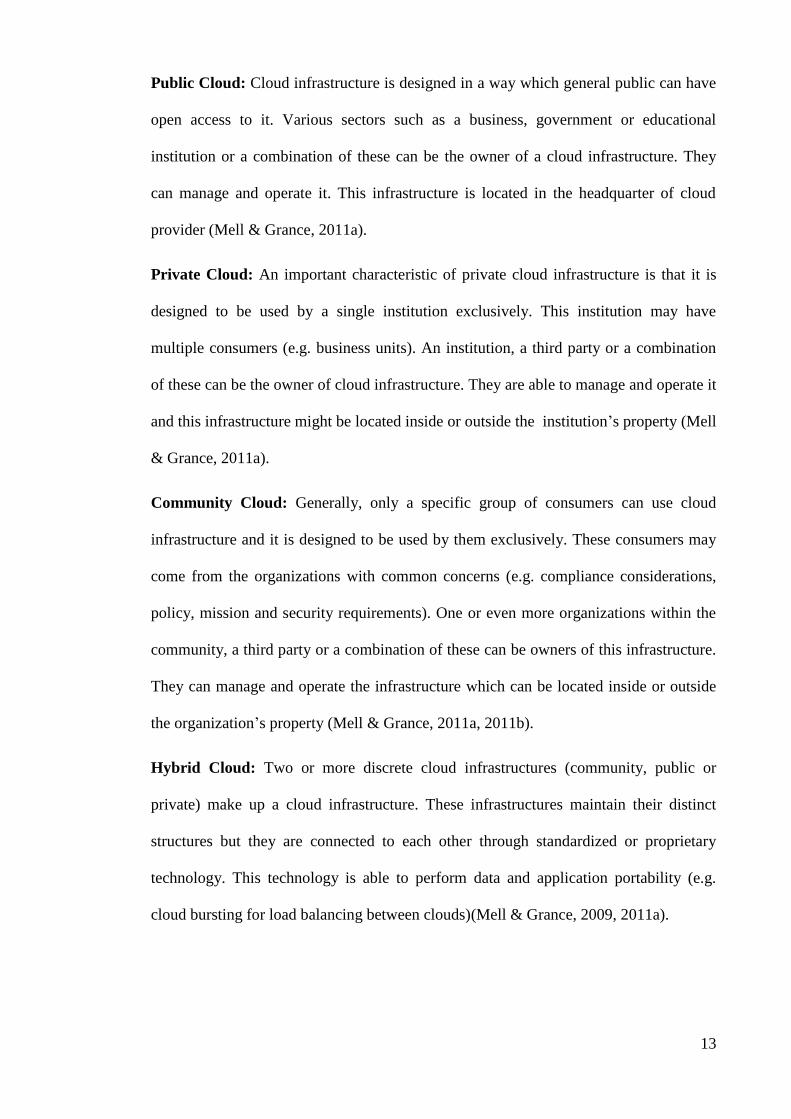
Public Cloud: Cloud infrastructure is designed in a way which general public can have
open access to it. Various sectors such as a business, government or educational
institution or a combination of these can be the owner of a cloud infrastructure. They
can manage and operate it. This infrastructure is located in the headquarter of cloud
provider (Mell & Grance, 2011a).
Private Cloud: An important characteristic of private cloud infrastructure is that it is
designed to be used by a single institution exclusively. This institution may have
multiple consumers (e.g. business units). An institution, a third party or a combination
of these can be the owner of cloud infrastructure. They are able to manage and operate it
and this infrastructure might be located inside or outside the institution’s property (Mell
& Grance, 2011a).
Community Cloud: Generally, only a specific group of consumers can use cloud
infrastructure and it is designed to be used by them exclusively. These consumers may
come from the organizations with common concerns (e.g. compliance considerations,
policy, mission and security requirements). One or even more organizations within the
community, a third party or a combination of these can be owners of this infrastructure.
They can manage and operate the infrastructure which can be located inside or outside
the organization’s property (Mell & Grance, 2011a, 2011b).
Hybrid Cloud: Two or more discrete cloud infrastructures (community, public or
private) make up a cloud infrastructure. These infrastructures maintain their distinct
structures but they are connected to each other through standardized or proprietary
technology. This technology is able to perform data and application portability (e.g.
cloud bursting for load balancing between clouds)(Mell & Grance, 2009, 2011a).

14
2.2.2 Cloud Computing Service Models
Cloud computing systems offer various services. In accordance with these services,
three kinds of cloud computing models can be formulated. These models include
platform as a service, infrastructure as a service and software as a service. Figure 2.2
depicts these models (Lewis, 2012; Linthicum, 2009; Mell & Grance, 2011a).
Figure 2.2: Cloud Computing Service Models
2.2.2.1 Infrastructure as a Service
This infrastructure offers a capability to a consumer which enables them to perform
storage, processing, networks and other basic computing resources. In this case, a
consumer is allowed to implement and execute an arbitrary software. This arbitrary
software may be operating systems and applications. The underlying cloud

15
infrastructure is designed in a way which a consumer cannot manage or control it.
However, the consumer can monitor or control storage, operating systems and
implemented applications. They can also manage selected networking components (e.g.
host firewalls) (Mell & Grance, 2011a).
2.2.2.2 Platform as a Service
The capability provided to the consumer is to deploy onto the cloud infrastructure
consumer-created or acquired applications created using programming languages,
libraries, services, and tools supported by the provider. The underlying cloud
infrastructure which includes servers, storage, network and operating systems cannot be
managed or controlled by a consumer. But they can monitor and control implemented
applications and change or adjust configuration settings within application-hosting
environment (Mell & Grance, 2011a).
2.2.2.3 Software as a Service
Software as a service offers a capability to consumers which enables them to access the
provider’s applications within cloud infrastructure. Consumers are allowed to gain
access to applications via different client devices which may be a thin client interface
like a web browser (e.g. web-based email) or a program interface. Again, the underlying
cloud infrastructure, which is consisted of servers, storage, network and operating
system, cannot be managed or controlled by consumers, nor can they have control over
personal or individual application capabilities, but they are allowed to change
configuration settings of limited user-specific applications moderately (Mell & Grance,
2011a). Chong and Carraro (2006) asserted that software as a service infrastructure
comprises multiple levels.

16
• Level 1: There is an application which is executed for one client organization
within a software as a service provider. It is close to traditional model of
Application Server Provider (ASP).
• Level 2: There is a software as a service system whose configuration can be
adjusted and a specific version of application is run for solely one client
organization.
• Level 3: There is a software as a service system which can be configured and a
specific and single version of application is used for multiple client
organizations.
• Level 4: There is a software as a service system which is designed as a single
version multi-tenant application and a number of application versions are
applied to execute within a load-balanced server farm.
Client organizations consider software as a service infrastructure as a way to apply
business-specific and out-of-the-box capabilities which are designed by a third party. In
doing so, they do not need to attain, manage and host several software packages or to
look for propriety solutions (Strowd & Lewis, 2010a).
2.2.2.4 Examples of Cloud Computing Providers by Service Models
Computational infrastructure which is accessible on the Internet is the major constituent
of infrastructure as a service. Compute cycles and storage are some examples of this
infrastructure. Organizations and developers can expand their IT infrastructure on
demand via infrastructure as a service (Lewis, 2012). Some examples of infrastructure
as a service are mentioned in alphabetical order below:

17
Amazon Elastic Compute Cloud (EC2): It is consisted of specific virtual
machines which are called Amazon Machine Images (AMI) and can be
implemented to execute within EC2 infrastructure (Amazon, 2012a).
Amazon Simple Storage Solution (S3): It offers dynamically scalable storage
resources (Amazon, 2012b).
Amazon’sotherData-Related Offerings: It offers elastic block storage whose
task is to offer block-level storage volumes to be utilized by Amazon EC2
versions. It also provides simpleDB, which is known as a non-relational data
store, and relational data store.
GoGrid Cloud Servers: It offers dynamically scalable computation and storage
resources (GoGrid, 2012).
Rackspace Cloud Servers: It provides dynamically scalable computing, storage
and load-balancing resources (Rackspace, 2012).
Application development platform is the basic foundation of platform as a service.
External resources can generate and host applications via this platform (Lewis, 2012).
Some examples of platform as a service offerings are mentioned in alphabetical order
below:
CloudBees: It provides a platform which is used to create, implement and
manage java applications (Bees, 2012).
Engine Yard: It provides a platform used to create and implement Ruby and
PHP applications which can be improved using add-ons (EngineYard, 2012).
Google App Engine: It provides a platform which is used to extend and run
Java and Python applications within Google’s infrastructure (Google, 2012a).

18
Heroku: it provides a platform to implement Python, Scala, Java, node.js, Ruby
and Clojure applications. All of these applications can be enhanced using add-on
resources (Heroku, 2012).
Microsoft Windows Azure: It provides on-demand compute and storage
services. It also creates a platform to develop and implement applications which
are executed on windows (Microsoft, 2012c).
Salesforce.com: It provides a platform which can be used to design and run
applications and elements which are purchased from AppExchange or custom
applications (Salesforce, 2012a).
Another model of software implementation is software as a service infrastructure. In
this infrastructure, an application is offered to clients by a third party and clients can
utilize it as a service on demand (Lewis, 2012). Some examples of software as a service
offerings are mentioned in alphabetical order below (Figure 2.3):
Google Apps: These services include document management, web site design
and management, calendar and web-based email (Google, 2012b).
Microsoft Office 365: Office Web Apps, file sharing, email, web conferencing
and calendar are among the services of this section (Microsoft, 2012b).
NetSuite: It provides applications of business-management software. They
comprise Customer Relationship Management (CRM), inventory management,
accounting, e-commerce, and enterprise resource planning (NetSuite, 2012).
Salesforce: It provides CRM software applications (Salesforce, 2012b).
SurveyTool: It offers a platform for web-based survey in order to gather
feedback from employees, focus group, clients and every active user base
(SurveyTool, 2012).

19
Zoho: It offers big package of web-based applications which can be primarily
utilized by enterprise (Zoho, 2012).
Figure 2.3: Examples of Cloud Computing Providers by Service Models
2.2.3 Cloud Computing Essential Characteristics
Figure 2.4 depicts five essential characteristics of cloud computing which are defined by
NIST (Mell & Grance, 2011a).
Figure 2.4: Cloud Computing Essential Characteristics
20
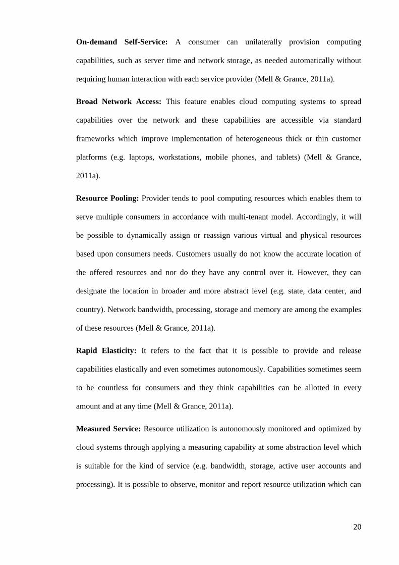
On-demand Self-Service: A consumer can unilaterally provision computing
capabilities, such as server time and network storage, as needed automatically without
requiring human interaction with each service provider (Mell & Grance, 2011a).
Broad Network Access: This feature enables cloud computing systems to spread
capabilities over the network and these capabilities are accessible via standard
frameworks which improve implementation of heterogeneous thick or thin customer
platforms (e.g. laptops, workstations, mobile phones, and tablets) (Mell & Grance,
2011a).
Resource Pooling: Provider tends to pool computing resources which enables them to
serve multiple consumers in accordance with multi-tenant model. Accordingly, it will
be possible to dynamically assign or reassign various virtual and physical resources
based upon consumers needs. Customers usually do not know the accurate location of
the offered resources and nor do they have any control over it. However, they can
designate the location in broader and more abstract level (e.g. state, data center, and
country). Network bandwidth, processing, storage and memory are among the examples
of these resources (Mell & Grance, 2011a).
Rapid Elasticity: It refers to the fact that it is possible to provide and release
capabilities elastically and even sometimes autonomously. Capabilities sometimes seem
to be countless for consumers and they think capabilities can be allotted in every
amount and at any time (Mell & Grance, 2011a).
Measured Service: Resource utilization is autonomously monitored and optimized by
cloud systems through applying a measuring capability at some abstraction level which
is suitable for the kind of service (e.g. bandwidth, storage, active user accounts and
processing). It is possible to observe, monitor and report resource utilization which can

21
provide accurate and transparent information for consumer and provider of the service
(Mell & Grance, 2011a).
2.2.4 Cloud Computing Actors
Significant actors play roles in NIST cloud computing reference architecture (Liu et al.,
2011), including cloud consumer, cloud broker, and cloud provider. Each actor is
regarded as a character (a person or an organization) who can engage in a process or
transaction and/or carries out tasks in cloud computing (Hogan, Liu, & Sokol, 2011).
There will be more accurate and detailed discussions about these actors in this section.
2.2.4.1 Cloud Provider
An individual or organization that is responsible for offering a service to interested
parties is known as a cloud provider. A computing infrastructure is needed for offering
services and the responsibility of a cloud provider is to obtain and manage this
infrastructure. In addition, a cloud provider has to operate cloud software which is able
to offer the services and conduct preparations to offer cloud services to cloud consumers
via network access (Hogan et al., 2011; Liu et al., 2011).
2.2.4.2 Cloud Broker
The more cloud computing expands and evolves, the more complicated it will be for
consumers to manage cloud services integration. A cloud broker rather than a cloud
provider may be called upon by a cloud consumer to deliver services. In fact, the
responsibility of a cloud broker is to monitor and observe the utilization, operation and
delivery of cloud services and to manage and handle the connection between cloud
consumers and providers (Hogan et al., 2011; Liu et al., 2011).
22
2.2.4.3 Cloud Consumer
The primary applier of a cloud computing service is cloud consumer. In fact, a cloud
consumer might be an individual or organization which is involved in a business
connection with a cloud provider and utilizes their services. A cloud provider offers a
service catalogue and a cloud consumer searches it to ask for the favourite services and
makes contracts with cloud provider and finally utilizes the services. Then, a cloud
provider charges cloud consumers for the services they have used and the consumers
have to make payments accordingly (Hogan et al., 2011; Liu et al., 2011) .
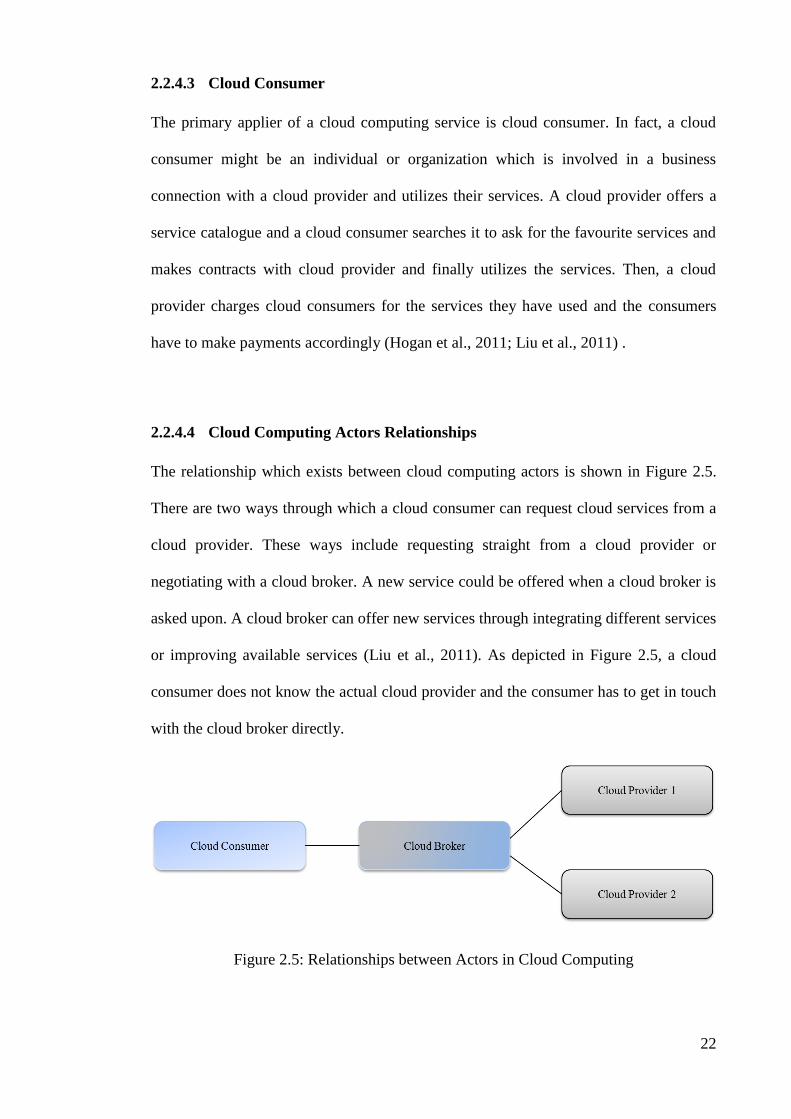
2.2.4.4 Cloud Computing Actors Relationships
The relationship which exists between cloud computing actors is shown in Figure 2.5.
There are two ways through which a cloud consumer can request cloud services from a
cloud provider. These ways include requesting straight from a cloud provider or
negotiating with a cloud broker. A new service could be offered when a cloud broker is
asked upon. A cloud broker can offer new services through integrating different services
or improving available services (Liu et al., 2011). As depicted in Figure 2.5, a cloud
consumer does not know the actual cloud provider and the consumer has to get in touch
with the cloud broker directly.
Figure 2.5: Relationships between Actors in Cloud Computing
23
2.2.5 Barriers to Cloud Computing Adoption
Organizations’ managers and directors have some worries about cloud computing
systems which impede in true implementation of cloud computing systems (Lewis,
2012; Strowd & Lewis, 2010a) (Figure 2.6):
Interoperability: One of the most important barriers of cloud computing
adoption is interoperability. The ability of resources on one cloud provider to
communicate with resources on another cloud provider.
Latency: A network (or internet if public clouds are to be provided) makes
cloud resources accessible. It creates latency within any kind of connection
between users and the environment.
Legal Issues: Typically, cloud suppliers look for inexpensive locations to set up
their server farms and data centers. As a result, there are some worries among
cloud computing users regarding fair information practices, data protection,
international data transfer and jurisdiction.
Platform or Language Constraints: In a number of cloud environments,
particular platforms and languages are solely supported.
Security: Data confidentiality is worry among cloud users. Most of the times,
organization’s managers are not fully aware of the locations cloud providers
save their data.

24
Figure 2.6: Barriers to Cloud Computing Adoption (Kostoska, Gusev, Ristov, &
Kiroski, 2012)
2.3 Interoperability
Numerous definitions have been given for interoperability. A number of reports and
technical papers offer definitions of interoperability (Breitfelder & Messina, 2000;
Coutinho, Cretan, & Jardim-Gonçalves, 2012; Cretan, Coutinho, Bratu, & Jardim-
Goncalves, 2012). For instance, the following four definitions of interoperability have
been given by Institute of Electrical and Electronics Engineers (IEEE) (Radatz, Geraci,
& Katki, 1990):
The ability of two or more systems or elements to exchange information and to
use the information that have been exchanged.
The capability for units of equipment to work efficiently together to provide
useful functions.

25
The capability ‒ promoted but not guaranteed ‒ achieved through joint
conformance with a given set of standards, that enables heterogeneous
equipment, generally built by various vendors, to work together in a network
environment.
The ability of two or more systems or components to exchange and use the
exchanged information in a heterogeneous network.
The US Department of Defense (USA Defense, 2001a) also introduces multiple
definitions of interoperability, in some of which the IEEE definitions have been
incorporated:
“The ability of systems, units, or forces to provide services to and accept
services from other systems, units, or forces, and to use the services so
exchanged to enable them to operate effectively together” (USA Defense,
2001b).
“The condition achieved among communications-electronics systems or items of
communications-electronics systems equipment when information or services
can be exchanged directly and satisfactorily between them and/or their users.
The degree of interoperability should be defined when referring to specific
cases” (USA Defense, 2001a).
“(a) Ability of information systems to communicate with each other and
exchange information. (b) Conditions, achieved in varying levels, when
information systems and/or their components can exchange information directly
and satisfactorily among them. (c) The ability to operate software and exchange
information in a heterogeneous network (i.e., one large network made up of
several different local area networks). (d) Systems or programs capable of
exchanging information and operating together effectively” (US Defense, 2001).

26
Brownsword, Carney, Fisher, Lewis, and Meyers (2004) defines interoperability as:
“Interoperability is the ability of a collection of communicating entities to (a)
share specified information and (b) operate on that information according to an
agreed operational semantics”.
The above-mentioned definition seems to be all-inclusive and comprehensive. The
characters in charge of communication are computer systems, individuals and/or a
combination of them. The information which is exchanged would be data or illustration
about the services and/or capabilities. The essential requisite of interoperability between
two systems is the capability to process data based upon a consented semantics. It
transcends the mere ability to trade or exchange those data.
2.3.1 Interoperability and Integration
There are two short definitions capture the key distinction between interoperability and
integration (Brownsword et al., 2004):
Interoperability is considered as the system property; interoperability relates to
the ability of information exchanges among the system elements.
Integration is considered as the process of creating a larger and more complex
entity by adding or combining individual parts. Integration is a step during
development that subsystems and other software components are combined to
produce a larger system or in which system of systems is produced from the
combination of systems.
Integrated system is produced from the integration process, meaning that in order to
achieve some system functions the elements of systems should work together. The
working together elements of the systems are said to be interoperable (Sledge, 2010).

27
2.3.2 Syntactic and Semantic Interoperability
Interoperability is much more than the capability of data exchanges between systems.
Interoperability needs a shared understanding of that information and how to act upon
it. As mentioned in Section 2.3, interoperability is defined as the ability of a collection
of communicating entities to share specific information, and operate on that information
considering the agreed operational semantics (Curts & Campbell, 1999; Heiler, 1995).
Syntactic interoperability is defined as the ability to exchange data, and semantic
interoperability is defined as the ability to operate on that data according to agreed-upon
semantics (Lewis & Wrage, 2006).
2.3.3 Approaches to Achieving Interoperability
If it were not for technology, it would be impossible to create interoperability between
systems. Several potential technologies are needed to build the systems which can
conduct interoperability between systems. Service Oriented Architecture (SOA),
components frameworks like Java 2 Platform, Enterprise Edition (J2EE) and .NET, web
service, model driven architecture are among these technologies, to name a few (Lewis
& Wrage, 2004).
2.3.3.1 Model Driven Architecture
Model Driven Architecture (MDA) is designed to assist software developers who want
to separate business and application logic from the basic execution platform technology
(Lewis & Wrage, 2004; Miller & Mukerji, 2003). Increasing abstraction in software
development is the most noticeable advantage of this framework. Software developers
do not like to encode platform-specific code in high-level language, instead they want to
work on formalizing models which are not dependent on platform but they can be

28
applied with specific application domain. MDA is usually used with the term of
architecture, but it does not refer to a specific software architecture or architectural
framework. In fact, a more comprehensive theoretical scope is defined by MDA. It
offers an all-inclusive framework to develop software.
The key notions of model-driven architecture have been put forward by Object
Management Group (OMG). In the process of encoding or writing the architecture,
novel standards are being proposed by working groups. These standards are essential to
actualize MDA notions in practice (Miller & Mukerji, 2003). MDA approach is
impartial to vendor and technology, but it is congruent with
Established OMG standards such as
Common Object Request Broker Architecture (CORBA)
Unified Modeling Language (UML)
MetaObject Facility (MOF)
XML Metadata Interchange (XMI)
Other industry standards such as Web services
Component frameworks such as
Sun’sJava 2 Platform, Enterprise Edition
Microsoft’s.NET
The fundamental concept of MDA is to define application and business logic within a
platform-free model or a series of relevant models. It tries to apply necessary tools
which are used to encrypt platform-specific utilization code from those models. In doing
so, it will be possible to create codes which depend on the middleware for instance, and
it won't be necessary to write them manually as they are in most of the cases these days.
Consequently, middleware experts do not need to engage themselves in software
development attempts since MDA tools and code generators provide all the essential

29
information about middleware-specific application. MDA framework boasts even more
advantages in development process, more coherent development process, more
developer productivity, platform-free models and domain model re-utilization are
among these advantages. It is expected that applications which are generated within this
framework exhibit more portability and more efficient interoperability in platforms. An
important fact which should not be neglected is that MDA tools are essential for gaining
these advantages and these tools are rather new. Therefore, it is not possible to totally
verify or approve their delivery due to scarce data and knowledge.
MDA puts emphasis on autonomous model transformations which is known as a
determinant factor making distinction between MDA and current utilization model of
software development. It also emphasizes on code generation since this framework
considers code as an accurate and operable system model. It is expected that
transformation capabilities would be applied in next-generation MDA tools in which
transformations can be defined within a vendor-neutral way in accordance with OMG
standards. Such tools will be absolutely different from the tools which are accessible
now. Code generation mode for current tools is proprietary. In platform-free models, a
software developer is able to re-utilize a similar model to activate implementation which
can be executed in different platforms. Another important capability which MDA tools
must possess is the ability to create codes that can connect different platforms to each
other. A three-tiered web application is an adequate example of suc tools. Every tier
executes on its own platform in this application (e.g. a servlet engine, J2EE application
server and a relational database). In more complicated cases, various operating systems,
middleware etc., may be engaged. MDA tools must have the capability to create codes
for different platforms and languages and even codes which are able to connect
application sections to a consistent system.

30
Models and Transformations
A model which is designed for MDA should be a formal model. It must be defined in a
language which possesses clear-cut semantics; therefore, the model can be processed via
an autonomous tool. Source code, UML class diagram, entity-relationship diagram, and
state charts are some examples of appropriate models. Yet, ad hoc box-and-line
diagrams are considered as appropriate models. Model transformations can be
accomplished through formal models and these transformed models can be
autonomously operated. The OMG’s MOF creates a standard repository for models;
hence, MDA is totally dependent on it. The OMG’s MOF also generates other meta-
data having standardized interfaces which make COBRA or Java applications’ contents
accessible. In an MOF repository, there might be models or models of models (mega-
models). What a meta-model performs is to introduce a language to define models. For
instance, UML can be described through a UML metamodel within MOF constructs.
The language which is used to define MOF meta-models possesses a sub-unit of UML
class diagrams as well as Object Constraint Language (OCL). Consequently, developers
that have background knowledge about UML are able to apply this model easily. Three
types of models are proposed by MDA including Platform Specific Models (PSM),
Platform Independent Models (PIM), Computation Independent Models (CIM). The
environment and the needs of a system are described by CIM or domain model whereas
PIM defines the framework and performance of a system without using the data of
execution platform technology. PSM provides detailed information about the ways a
system applies platform. Utilization code is known as another platform-specific PSM in
this sequence of models. A system PIM or PSM can be changed into a similar system
model via model transformation. An example of this is the conversion of PIM to PSM
or PSM to implementation code. Extra or additional information may be needed for
transformations. Figure 2.7 depicts such information within empty box. This additional

31
information contains various elements such as a specific architectural technique or a
pattern of data access which can be applied in PSM (Miller & Mukerji, 2003). MDA
lacks a concrete and accurate criteria to specify if a model depends on a platform or not.
Developers’ standpoints usually determines such a criteria. Therefore, PIM and PSM
are accompanied with a collective framework which are known as extreme cases. The
MDA tools which are available now propose model transformations based upon a
vendor-specific way. Hence, exchange of transformations between tools of various
vendors is not achievable. OMG is struggling to propose a declarative transformation
description language Queries, Views and Transformations (QVT). As a matter of fact,
QVT is known as a metadata repository which is standardized. A model transformation
based upon vendor-neutral description is truly supported by this repository. However,
this process is evolving and is in its initial stages.
Figure 2.7: Model Transformation

32
MDA Tools
Although a large number of tools that are currently available in market are said to
support MDA, they cannot fully support MDA concepts yet since those concepts are not
completely established. Moreover, what exactly MDA tools have to encompass is not
thoroughly known. Therefore, no standard concept is currently available to conform a
MDA tool and tool vendors must count on their own perceptions about MDA tools
when they have to define capabilities of tools (ObjectManagementGroup, 2004). In
OMG website, a list is provided about the companies which remain loyal to MDA and
their products (ObjectManagementGroup, 2004). Most of the tools which have been
designed so far can only be used to create one single execution platform, mainly J2EE.
MDA and Interoperability
MDA possesses two important dimensions which are involved with interoperability.
1. Interoperability of Applications Across Platforms: In MDA framework,
application interoperability refers to the environment in which software
applications are able to collaborate with each other while they do not have to
rely on execution platform of every separate application. Some codes which are
created by MDA tools can bring about such interoperability. These codes are
generated according to data about (a) target platforms, which is defined and
encrypted in models and model transformation (b) interoperating sections of
model. These codes which are called bridge codes promotes syntactic
interoperability. Nonetheless, there is no guarantee about semantic
interoperability since the execution semantics of models are not accurately
defined by MOF-based meta-models. Semantic interoperability requires a
thorough and adequate definition of data and the operations which can be

33
performed on that data. This definition could specify syntactic and semantic
facets. Such information might be presented into two forms. It can be proposed
as additional information for model transformations, or it can be presented as a
model component. Presently, there are no tools which can support semantics
definition with high accuracy and adequacy. Hence, there might be different
semantics of implementations from different tools. Another important facet of
these models is their scope and thoroughness. Sometimes, a complete model can
be generated which is able to create all necessary application codes from a
model. But other tools can merely generate models which cover only parts of the
system. Thus, developers need to apply business logic in implementation
programming language. Under such conditions, tools cannot guarantee
interoperability since programmers’ implementations might be based upon
contradictory interpretations.
2. Interoperability of MDA Tools: It refers to the extent of openness a MDA tool
environment possesses which enables developers to share models with other
tools offered by different vendors. The best framework for such model sharing
or exchange via XMI has been proposed by MDA so far. XMI is able to propose
meta-models and models as XML schemas and XML documents. There still
exist some worries which may cause problems in the future. These worries are
concerned with graphical views of models and the sharing of model
transformation specifications. Presently, the only type of interoperability which
exists within current tools is syntactic interoperability and it is based upon a
shared exchange style. The semantics of shared information are usually
dependent on tools. Model elements which are generated by the majority of
current tools are mostly dependent on tools. Hence, re-generation of these
elements in another tool becomes difficult. Such elements can be syntactically

34
supported by XMI without any serious problem; however, the tool that is
receiving these elements cannot operate on the data meaningfully.
2.3.3.2 Service Oriented Architecture
Service Oriented Architecture (SOA) can be simply defined as an architecture which is
generated around a group of services using well-defined interfaces. This architecture is
close to Object Request Brokers (ORB) or Distributed Component Object Model
(DCOM) with regard to COBRA description. Connections or interactions between these
services are controlled and conducted by a system or application (Lewis & Wrage,
2004).
A software service is self-controlled, discoverable and coarse-grained. It is able to
connect with applications and other services within an asynchronous, loosely coupled
and message-based model (Brown, Johnston, & Kelly, 2002). The well-known models
related to communication include:
Publish-subscribe system like Java Messaging Service (JMS)
Web services using Simple Object Access Protocol (SOAP) and Web Services
Description Language (WSDL)
Message-Oriented Middleware (MOM) like IBM websphere MQ
The major distinction between SOA and DCOM or CORBA is concerned with the terms
of "discoverable" and "coarse-grained" which are used in the former definition of a
service. It seems necessary to discover services at run time and design time. This
discovery must be achieved through their peculiar identity, type of service, and interface
identity. An essential feature of services is that they typically being coarse-grained. It
means they must be able to apply more functionality and process broader range of data

35
collections. It is in contract with components of a component-based model. A credit
card validation service can be a conventional example of a service.
There are several ways through which a customer can ask for a service (Brown et al.,
2002; ServiceArchitecture, 2004). These ways include:
1. Directly requesting from a service provider.
2. Referring to a directory service to look up a service provider in accordance with
some standards. The location of a service is introduced by directory service.
Through the location, a service customer can get a service provider.
3. Consulting with a service broker to convey the request to one or more directory
services.
HP’s E-Speak (Karp, 2003), and Sun’s Jini (SunMicrosystems, 2004b), and web
services with SOAP and Universal Description, Discovery and Integration (UDDI)
service are among the examples of service oriented architectures. In Section 2.3.3.3,
web services will be elucidated in more detail.
SOA and Interoperability
Interoperability in a service-oriented architecture refers to a condition in which every
probable customer could request a service (Stevens, 2002). Such a definition for
interoperability encompasses narrower realm compared with the general definition that
is used in this research. However, SOA still possesses a number of features which allow
for this type of interoperability.
Common Payload and Protocol: All probable customers of services are fully
aware of payload format and protocol and ask for an interface which is provided
by a service using this format.

36
Published and Discoverable Interfaces: A published and discoverable
interface manages every service. As a result, systems will be able to assign
services to the most suitable and appropriate requests.
Loose Coupling: Standard, dependency-decreasing, decoupled message-
oriented frameworks like XML document exchanges conduct relationships
between services and customers.
Multiple Communication Interface: Communication interfaces which are
disparately defined are used to apply services. For example, there might be
MOSeries, Internet Inter-ORB Protocol (IIOP), and web services adapters in a
service to provide assistance to three different kinds of customers.
Composability: Coarse-grained and reusable elements make up services which
offer their functions via a well-defined interface. Accordingly, a composition of
services leads to generation of systems and inclusion of new services enhances
those systems.
Service-based architecture seems to be efficient from a syntactic approach. A serious
problem is to specify adapters’ number which should be used to apply and the right
granularity of service interfaces. It is due to the fact that the way systems utilize services
is not fully understandable. A network which is built as a result of service request and
service response exchange creates a framework to execute services. Customers would
get information beyond what they actually require in their response message when
service interfaces are being too coarse-grained. Under this circumstance, customers
need to refer to the service frequently to receive the necessary information they look for.
However, semantic approach puts forward a different view. The description of a service
interface and the way its information meaning is distributed among probable customers
of the services determines semantic interoperability. A large number of researches have
been conducted in this field since it appears to be a serious problem. How can we

37
distinguish the actual and true contents of a service? How is it possible to get connected
with that service? What is the Quality of Service (QoS) it can provide? These are the
questions which are going to be answered in Section 2.3.3.3 regarding web services.
2.3.3.3 Web Services
A web service can be simply defined as an instantiation of a service-oriented
architecture only if it is possible to implement the following elements (Lewis & Wrage,
2004).
Simple Object Access Protocol (SOAP) over HyperText Transfer Protocol
(HTTP) is utilized to transfer payload.
The directory service which is offered is based upon Universal Description
Discovery and Integration (UDDI).
Web Services Description Language (WSDL) is used to define service
interfaces.
Although technologies can be combined in a large number of ways, this combination is
known as the most well-known instantiation. Hence, it is possible to use the terms of
SOA and Web services interchangeably. Several factors are involved in increasing
success of web services. Some of these factors are mentioned below.
Standard internet technologies assist systems to connect with each other
dynamically.
Although services are generated only once, they can be re-utilized several times.
Every programming language can be applied to provide services
Since HTTP is the framework which is used to carry over communication, there
will not be any worries regarding firewalls among service consumers.

38
It is possible for systems to publicize their capabilities for other systems.
Amazon web services, for instance, make catalogue data accessible, monitor
shopping cart and commence checkout process through web services (Amazon,
1996).
Autonomous discovery and web services composition are standards like
Business Process Execution Language for Web Services (BPEL4WS), WS-
Routing, Web Services Conversation Language (WSCL), WS-Coordination,
WS-Transaction and WS-Security are trying to achieve.
Web Services and Interoperability
Many vendors and users believe that web services are connected with interoperability
since interoperability is regarded as an ability to apply a service in various programming
languages and to connect via popular and platform-free standards and protocols. Such
definition for interoperability seems to offer narrower scope than the definition
presented in this research, as it is the case for SOA definition. The Web Services
Interoperability (WS-I) is a new group which offers instruction about implementation of
web services standards. This organization has been founded in early 2002, and is an
open industry attempt whose goal is to develop web services interoperable across
platforms, applications and programming languages. A large group of web service
leaders are gathered by this organizationtoaddresscustomers’ needs. They try to offer
guidance, suggest practices and supply resources to promote interoperable web services
(WS-I, 2004). The organization have lately made its tools available in order to examine
interoperability of WS-I basic profile in web service implementation. The future of web
services seems to be encouraging from a syntactic standpoint. They are witnessing
remarkable growth since they are based upon popular standards and organizations such
as WS-I. Yet, a serious problem which still remains is that new standards come into

39
existence; therefore, different parties or agents which apply web services have different
perceptions or interpretations about new standards. Since SOAP offers diverse possible
choices regarding formats, envelops, and transport protocols, this problem is more
serious in it. In addition, web services are faced with a lot of restrictions according to a
semantic standpoint, because only keywords are involved in discovering web services.
Hence, the capability of run-time discovery, which is a necessity for autonomous web
service composition, is restrained. Large number of researchers and industrial partners
have gathered and cooperated in a collaborative attempt by W3C which is known as
semantic web. Their goal is to tag information in the web so that software agents who
seek particular pieces of information can retrieve them. Semantic web services are
generated through combination of web services with semantic web. A web service
which is defined in a machine-understandable language along with formal semantics is
called a semantic web service. The fundamental concept behind it is to define web
services in a manner that information sharing can be autonomously conducted by
applications and interoperability is enhanced. The DARPA Agent Markup Language
(DAML) program aims to generate a web service ontology in accordance with OWL
(Web Ontology Language) called OWL-S (previously known as DAML-S). They also
provide tools and agent technology which can be used to conduct service automation in
semantic web (Paolucci & Sycara, 2003; Sycara, 2003). When applications rather than
humans are supposed to process document information, OWL will be applied (W3C,
2004). It is more probable to have semantic interoperability when ontologies like OWL-
S or other ontologies with OWL are applied. However, such ontologies have a long road
to evolve and they are mainly applied in researches.

40
2.3.3.4 Component Frameworks
Software engineering developers have recently taken Component-Based Development
(CBD) more seriously. It is feasible to integrate independent and reusable components
and to generate large software systems via CBD. Java 2 Platform Enterprise Edition
(J2EE) and Microsoft.net (.NET) are two major component frameworks which are
compatible with this model (Lewis & Wrage, 2004).
The focus area of present research is system-of-systems interoperability rather than
interoperability between components forming a whole system. There are two reasons
why these two component frameworks have to be scrutinized. (a) due to a general
assumption that there will be flawless interoperability between systems which are
generated within similar component framework. (b) Due to increasing interest in
interoperation between systems which are built in accordance with J2EE and .NET.
Java 2 Platform Enterprise Edition (J2EE)
J2EE which is generated by Sun Microsystems proposes a standard framework to
design component-oriented multi-tier enterprise applications (SunMicrosystems,
2004a). A series of APIs (application program interfaces) are introduced by J2EE to
create reliability, scalability, availability and security in applications which are designed
according to this component framework. Java language is the main language applied to
generate components. Many application servers which employ J2EE specifications are
accessible for vendors. JBoss, BEA Weblogic and IBM Websphere are some examples
of these J2EE specifications. J2EE can operate on a large number of operating systems
such as Windows, Sun Solaris, Unix and Linux. In addition, a compatibility test suite is
introduced by Sun to guarantee coherent utilization among vendors. A certificate will be
granted only to those vendors who successfully pass this test.

41
J2EE is consisted of a number of technologies and APIs including:
• Java DataBase Connectivity (JDBC)
• Java Naming and Directory Interface (JNDI)
• Java Messaging Service (JMS)
• Enterprise JavaBeans (EJB)
• Java Server Pages (JSP) and Servlets
• Java Transaction API (JTA)
Standards such as SOAP, WSDL, UDDI, and XML are fully compatible with current
version of J2EE. With regard to interoperability, it can be said that web services
interoperability is guaranteed and it is conducted via supporting WS-I basic profile. Sun
has been acquired by Oracle.
Microsoft .NET
Microsoft .NET is a development environment used to generate distributed enterprise
applications. The basic element of .NET is its .NET framework. There are two major
sections in this framework, including the .NET framework class library and the
Common Language Runtime (CLR). It is possible to write programs in numerous
programming languages via CLR since it is able to convert them into Intermediate
Language (IL). .NET signals can be dispatched, received and managed through IL. The
main components of the .NET Framework class library are ASP.NET, Windows Forms
and ADO.NET and each one is used for a specific task. ASP.NET's task is to develop
web applications and web services, Windows Forms are used for user interface
development and ADO.NET is applied to connect databases.
Microsoft.net has other components including:
• Active Directory Services
42
• Windows Server System Components such as SQL Server 2000 and Exchange
Server 2003
• Visual Studio .NET Development System
• Windows Server 2003
Standard frameworks such as SOAP, WSDL, UDDI and XML are fully compatible with
.NET regarding interoperability (Microsoft, 2012a).
J2EE, .NET, and Interoperability
With regard to a syntactic standpoint, there is an assumption that two systems which are
generated within a similar framework can have flawless interoperability. This
assumption is not always correct. Since J2EE is a standard framework, different
application server implementations can bring about many differences and it may cause a
number of problems. For this reason, a J2EE certification program is used in Oracle.
However, since .NET possesses a proprietary essence, it is not faced with this problem
seriously. (All .NET Frameworks are thoroughly supported by Microsoft and it provides
different versions of the framework which can execute in most of Windows version).
Several methods can be used to create constructive interoperability between J2EE and
.NET.
• Integration brokers such as IBM MQSeries Integrator, Mercator
CommerceBroker, Microsoft BizTalk Server, and WebMethods Enterprise
Services Platform
• A common database
• Message-oriented middleware such as IBM MQseries, Microsoft Message
Queue (MSMQ), BEA MessageQ, and Tibco Enterprise Message Server

43
• Runtime bridges such as Borland’s Janeva, Intrinsyc’s J-Integra for .NET
(Ja.NET),andJNBridge’sJNBridgePro
• Web services
Data type mismatch among languages can cause three major problems when systems try
to share data and knowledge. For example, when J2EE components and C# applies java
language for .NET components, such a problem emerges. There is a list of such
problems below (Microsoft, 2012a).
• Complex data types: composition of different data types creates complex data
types which have to be disclosed to other parties in order to bring about
appropriate mapping
• Non-existent data types: sometimes, a data type in a language cannot be found in
another language. Specialized data types which present a set of facets like
vectors are some examples of these data types.
• Primitive data type mappings: existence of identical data type in two languages
cannot guarantee mapping between them. It is more evident with regards to
floating point numbers and strings.
Plenty of experiments and testing have to be performed in order to ascertain that these
problems are no longer existing. With regard to a semantic viewpoint, There are no
major differences between the approaches which have been scrutinized so far. When the
data that are being shared are not understandable for all parties, it will be impossible to
achieve semantic interoperability. In a case where applications are presented as
packages of web services, the semantic interoperability specifications discussed in
Section 2.3.3.3 must be implemented.

44
2.4 Definitions of Cloud Computing Interoperability
Cloud computing systems define interoperability as cloud providers’ capability to
collaborate or interoperate with each other and to create a federation of clouds (Cohen,
2009; Loutas, Kamateri, Bosi, & Tarabanis, 2011). It is depicted in Figure 2.8.
Accordingly, collaboration and cooperation require interoperability. Cloud computing
interoperability will be defined, and analyzed in this chapter in detail.
Figure 2.8: Cloud Computing Interoperability
According to the Use Case Cloud Computing Discussion Group (2010), what is
particularly important in interoperability is that the receiving systems must be able to
figure out the exchanged information. This means that

45
“Interoperability is the ability to write code that works with more than one
cloud provider simultaneously, regardless of the differences between the
providers”.
This means that in cloud computing systems, it alludes to the fact that codes need an
API to interact with every system.
Goyal (2010) gives the following definition, identifying a number of basic concepts:
“Cloud computing interoperability includes the ability of some application code
to run on more than one provider Cloud Computing Environment (CCE),
regardless of the differences between the CCE. It also includes process
execution, security, portability, migration/cloning control, standards,
transparency, and manageability and regulatory compliance”.
Oberle and Fisher (2010) define interoperability as the cooperation of multiple clouds to
support an application :
“Interoperability involves software and data simultaneously active in more than
one Cloud infrastructure, interacting to serve a common purpose”.
Cohen (2009) clarifies it as
“Cloud computing interoperability is the ability for multiple cloud providers to
work together or interoperate”.
According to Oberle and Fisher (2010), cloud computing interoperability, portability
and compatibility are closely related terms and often confused . Cohen (2009) clarifies
the similarities and the differences among these terms in an attempt to exemplify and
differentiate them:
“Cloud computing interoperability is the ability for multiple cloud providers to
work together or interoperate. Cloud compatibility and portability answer to the
question “how?”. Cloud compatibility means application and data that work

46
with the same way regardless of the cloud provider, whereas cloud portability is
the ability of data and application components to be easily moved and reused
regardless of the provider, operating system, storage, format or API”.
These observations lead us to a more abstract definition of cloud computing
interoperability:
‘The ability of resources on one cloud provider to communicate with resources
on another cloud provider”.
2.4.1 Interoperability and Portability in Cloud Computing
The two brief definitions below truly differentiate interoperability from portability. It is
shown in Figure 2.9.
Interoperability: It alludes to a situation in which a number of connecting
sections are able to exchange particular information and execute on that
information based upon a set of consented functional semantics (Brownsword et
al., 2004).
Portability: It is the capability of transferring workloads and data between
providers (Cohen, 2009; Stravoskoufos, Preventis, Sotiriadis, & Petrakis, 2014).
Figure 2.9: Interoperability and Portability in Cloud Computing

47
What portability means in cloud computing environments is that probable customers are
eager to realize if they are able to transfer their data or applications within multiple
cloud environments with reasonable expense and minimum disturbance. As far as
interoperability is concerned, users want to be able to connect with each other across
various clouds. Some frameworks have to be designed by cloud providers in order to
develop data portability, service interoperability and system portability (Buyya, Ranjan,
& Calheiros, 2010). What data portability refers to is the capability of cloud consumers
to transfer data items in or out of a cloud and/or to apply a disk for transferring huge
data. When cloud consumers are able to apply their data and services within various
cloud providers through a unified management interface, service interoperability can be
achieved. The transfer of a thoroughly-stopped virtual machine version or a machine
image between providers can be accomplished by system portability.
2.4.2 Interoperability Types in Cloud Computing
This section provides an overview of different cloud computing interoperability
viewpoints. It attempts to illustrate the different interoperability classifications and to
explore the characteristics/aspects of each category.
An approach in delimitating cloud computing interoperability is presented by Sheth and
Ranabahu (2010a, 2010b), where cloud computing interoperability is closely associated
with the type of heterogeneity that arises during the interoperation of clouds. Clouds
interoperate to meet the needs of client applications using infrastructure, platforms or
services coming from different clouds. Therefore, interoperability is divided in three
subcategories (see Figure 2.10): (1) interoperability in Infrastructure as a Service level;
(2) interoperability in Platform as a Service level; and (3) interoperability in Software as
a Service level.

48
Figure 2.10: Interoperability Types in Cloud Computing Environments
49
2.5 Cloud Computing Interoperability
This section presents the literature review on cloud computing interoperability in detail.
There are several initiatives trying to address cloud computing interoperability through
frameworks and models. Their analyses expose the gaps and deficiencies that existing
cloud computing frameworks and models suffer from. The discussion and findings at
the end of this section displays the existing gap and problem for interoperability in
cloud computing.
2.5.1 Aneka
Both private cloud resources and public cloud resources can be offered by Aneka
Platform as a Service. In fact, Aneka Platform as a Service is responsible for providing
all these cloud resources. Desktop, clusters and virtual data centers via VMWare, Citrix
Xen Server are among the private cloud resources and Windows Azure, Amazon EC2
and GoGrid Cloud Service are examples of public cloud resources. Basically, there are
two central sections involved in Aneka technology which include:
Software Development Kit (SDK): It refers to interfaces that are used for
application programming and the necessary tools that are needed to develop
applications rapidly. Three well-known cloud programming models can be
applied with Aneka APIs. These models include task, thread and map reduce.
A Runtime Engine and Platform: It is employed to monitor implementation
and execution of applications on both private and public clouds.
Figure 2.11 shows Aneka’sarchitecture(Vecchiola, Chu, & Buyya, 2009). The node is
in close contact with the fabric services, and this connection is conducted via Platform
Abstraction Layer (PAL). The major task of fabric services is to run hardware profiling
and to provide dynamic resources.

50
The fabric services is directly interact with node via Platform Abstraction Layer and
runs hardware profiling and supplies dynamic resources. The critical section of Aneka
middleware is called foundation services. This section offers a series of key features
over every Aneka containers, each of which can be specifically employed to execute a
specific series of tasks or jobs.
Scheduling and operation of cloud applications are conducted in execution services. The
container is responsible for conducting a large number of services which encompass
additional services such as persistence and security. Various components and tools are
offered by application level which is located over Aneka middleware. These tools and
components are designed to achieve the following goals:
1. Facilitate expansion and development of applications
2. Transfer or port available applications to the cloud
3. Monitor and manage the Aneka cloud

51
Figure 2.11: OverviewoftheAneka’sFramework(Vecchiola et al., 2009)
2.5.2 Cloud Exchange Federated Cloud
The term "Intercloud" is used to refer to a federated cloud computing environment
under which scalable provisioning can be performed in changing conditions (Buyya et
al., 2010) (Figure 2.12). This federated framework or architecture is consisted of three
major sections; including client brokering, coordinator services and cloud exchange.
The responsibility of a cloud broker is to receive a client’s request and to fulfil their
requirements. The cloud coordinators’ task is to broadcast and distribute services to
federation. Meanwhile, the cloud exchange tries to create closer connection between
service providers and clients. The total infrastructure requests of application brokers are
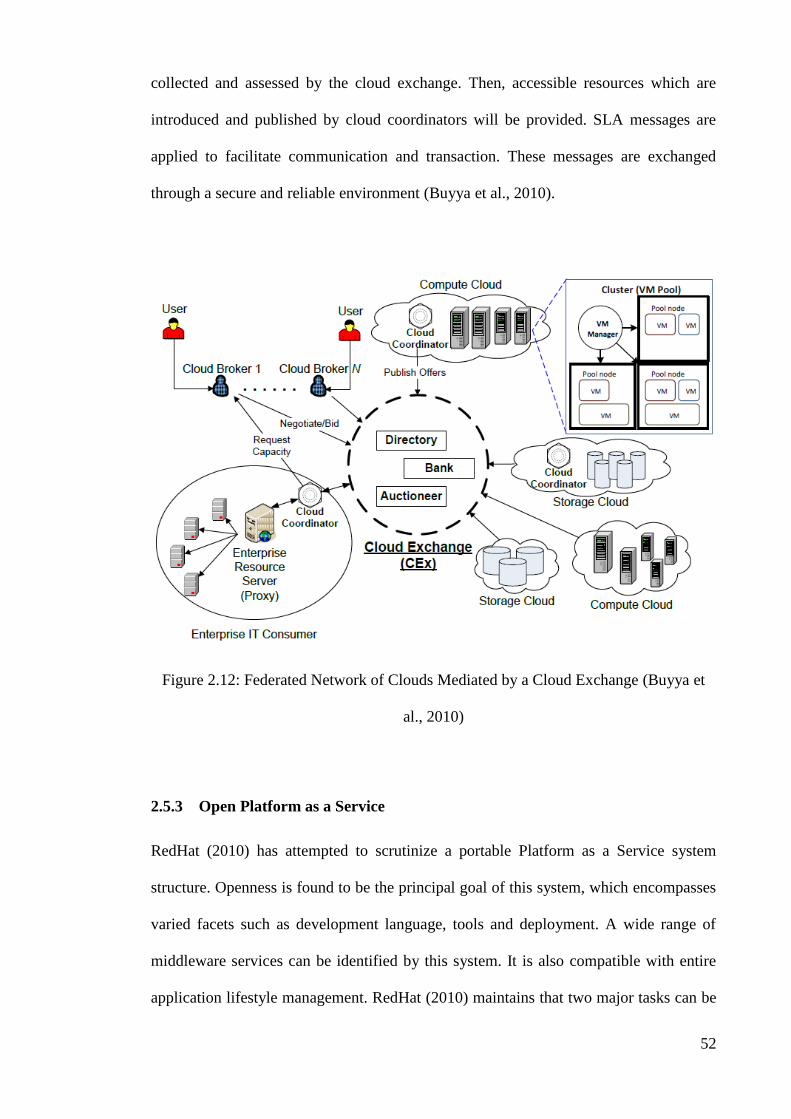
52
collected and assessed by the cloud exchange. Then, accessible resources which are
introduced and published by cloud coordinators will be provided. SLA messages are
applied to facilitate communication and transaction. These messages are exchanged
through a secure and reliable environment (Buyya et al., 2010).
Figure 2.12: Federated Network of Clouds Mediated by a Cloud Exchange (Buyya et
al., 2010)
2.5.3 Open Platform as a Service
RedHat (2010) has attempted to scrutinize a portable Platform as a Service system
structure. Openness is found to be the principal goal of this system, which encompasses
varied facets such as development language, tools and deployment. A wide range of
middleware services can be identified by this system. It is also compatible with entire
application lifestyle management. RedHat (2010) maintains that two major tasks can be
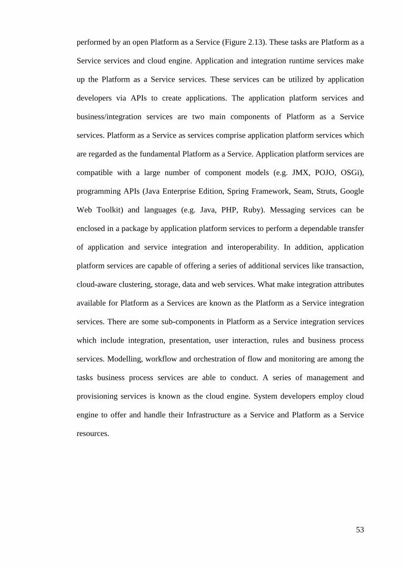
53
performed by an open Platform as a Service (Figure 2.13). These tasks are Platform as a
Service services and cloud engine. Application and integration runtime services make
up the Platform as a Service services. These services can be utilized by application
developers via APIs to create applications. The application platform services and
business/integration services are two main components of Platform as a Service
services. Platform as a Service as services comprise application platform services which
are regarded as the fundamental Platform as a Service. Application platform services are
compatible with a large number of component models (e.g. JMX, POJO, OSGi),
programming APIs (Java Enterprise Edition, Spring Framework, Seam, Struts, Google
Web Toolkit) and languages (e.g. Java, PHP, Ruby). Messaging services can be
enclosed in a package by application platform services to perform a dependable transfer
of application and service integration and interoperability. In addition, application
platform services are capable of offering a series of additional services like transaction,
cloud-aware clustering, storage, data and web services. What make integration attributes
available for Platform as a Services are known as the Platform as a Service integration
services. There are some sub-components in Platform as a Service integration services
which include integration, presentation, user interaction, rules and business process
services. Modelling, workflow and orchestration of flow and monitoring are among the
tasks business process services are able to conduct. A series of management and
provisioning services is known as the cloud engine. System developers employ cloud
engine to offer and handle their Infrastructure as a Service and Platform as a Service
resources.

54
Figure 2.13: The Design of an Open Platform as a Service System (RedHat, 2010)
2.5.4 Red Hat Reference Cloud Computing Architecture
RedHat (2009) via JBoss Enterprise introduced reference cloud computing architecture
(Figure 2.14). The major goal behind this architecture was to propose a framework for
open source software which can be implemented to meet various application needs.
Openness, flexibility and scalability are the critical aspects of reference architecture.
Such attributes are the ones enterprises are looking for when they try to develop and run
their applications. A wide range of middleware functions can be properly performed by
this architecture. These functions are as follows:
1. Application and services runtime services
2. Process management and service integration
3. Data integration and business intelligence services

55
4. User interaction services (Portal Platform)
5. Systems management and monitoring
6. Integrated development tooling
Figure 2.14: A Reference Architecture Released by Red Hat (RedHat, 2009)
2.5.5 Cisco Reference Cloud Computing Architecture
Cisco’s reference architecture for cloud computing (Figure 2.15) is made up of five
architectural layers, connected via APIs and repositories (Cisco, 2009).
56
Figure 2.15: Cisco’sCloudReferenceArchitecture(Cisco, 2009)
In the hierarchy of layers in this architecture, the lowest layer is called technology layer,
which is made up of three fundamental constituents. These constituents include
compute, network and storage. The security layer is responsible for monitoring the
entire (end to end) sections of architecture. It is located above foundation layer and
performs tasks such as encryption, incident detection, and resource access and data
control. Lower layers of this architecture are connected to each other by service
orchestration layer. These layers are integrated to produce a service which can be
delivered. Configuration repositories are needed to activate and run this layer. The
configuration repositories contain critical information and assign components of
technology to service components. Infrastructure and service management tasks are
performed in a layer which is called service delivery and management architecture
layer. These tasks range from compliance and control functions, which monitor the
applications and data, to service-level management functions which diminish and
execute SLAs. Consumer-facing layer is located at the peak or highest layer of the

57
architecture. A portal solution is often employed to display this layer. End users are able
to demand, define and handle services in this layer.
2.5.6 IBM Reference Cloud Computing Architecture
IBM’sreferencearchitecture (Figure 2.16) provides a comprehensive set of capabilities
required to address the needs of end-users, providers, and creators of cloud services
(Dodani, 2009).
Thecreator’scapabilitiesallow(a)designandbuild,(b)store,(c)deployment,and(d)
management of the entire lifecycle of“images”,wherethe“image”canincludetheIT
resources, the operating system, the middleware, and the applications.
The service consumer component provides capabilities that serve both the end-users and
the operators to manage the infrastructure, such as ensuring that the images that can be
accessed are defined in a catalogue.
The key capabilities of the reference architecture are defined in the service provider
component. The bottom layer defines the capabilities of the virtualized infrastructure
while the next layer provides middleware capabilities such as image deployment,
security, workload management and high-availability. The middleware is built in order
to deliver services and information according to well defined SOA and information
architecture. The lifecycle management plays a major role in IBM’s reference
architecture. Specifically, the architecture provides tools to manage user requests
(manage the self service requests, the lifecycle of images and the provisioning of images
based on the request) and to handle qualities of service associated with the delivering
images (availability, backup and restore, security and compliance, and performance
management). Virtualized resources and workloads demand also management.

58
Furthermore, the usage and accounting management help define business and IT
metrics, meter the usage of services and resources and accounting.
Figure 2.16: IBM’sReference Architecture (Dodani, 2009)
2.5.7 Cloud Development Stack Model
Cloud Development Stack Model (SaugatuckTechnology, 2010) enables a cost-effective
development in the cloud while implements a number of Platform as a Service
requirements such as scalability, reliability, highly availability, flexibility in
deployment, use interfaces and portability. The model provides an objective framework
of what needs to be included by a perfect Platform as a Service in order to develop and
deliver efficient and effective cloud solutions. The model and its core components,
depicted in Figure 2.17, are summarized below.

59
Figure 2.17: The Cloud Development Stack Model (SaugatuckTechnology, 2010)
The fundamental Platform as a Service capabilities like software, associated
infrastructure and hardware are provided or offered by infrastructure layer. The job of
associated infrastructure is to develop and progress applications. The responsibility of
middleware layer is to provide convenient capabilities such as multitenancy,
virtualization and security. These capabilities play a major role in developing effectual
cloud computing applications. In addition, middleware layer is able to offer other
services like content management systems, runtimes, different workflow engines,
BPMS and data services. The pivotal layer in Platform as a Service model is
development layer which is located above middleware layer. The most important
responsibility of this layer is to develop the actual activities and actions of the system.
Development layer is regarded as the most intricate layer in this proposed model
because it encompasses the most crucial languages, components, libraries and tools
which developers need to test or examine, develop, connect and refine or process the
services. Ultimately, there is application layer which is responsible for implementing
and developing two sorts of applications in cloud computing system. These applications

60
include ported cloud apps and native cloud apps. Native cloud applications are those
cloud solutions developed for the cloud, in the cloud, using one or more platform as a
service environments. Ported cloud applications are traditional-style, on-premise
application solutions re-engineered to run in the cloud. These are usually migrated,
single-tenant, virtualized applications re-architected to some degree in order to call to
the middleware. Another layer is analysis and metering layer which contains analyzing
tools and "dashboards" needed for pricing and Platform as a Service utilization. In this
layer, basic or elemental management capabilities are offered to developers in order to
measure or meter Platform as a Service utilization and match it with their performance
guarantees and Platform as a Service SLAs. Furthermore, the constituents of this layer
can present another capability which enables developers to observe and estimate
development costs of models.
As its name denotes to, administration layer has the responsibility of creating tools
related to administration and governance. These tools administer order and discipline
and facilitate efficient and effectual operations of tasks in cloud system. This layer is
responsible for offering some crucial capabilities such as data dictionary services,
directory services and configuration management/version control system.
2.5.8 Next Generation Cloud Architecture
Next generation cloud architecture has lately been proposed by some scholars. Sarathy,
Narayan, and Mikkilineni (2010) were the first ones to put forward this notion. They
have envisaged a cloud architecture in which there will be a distinct boundary between
virtual resource and physical resource management. They have mentioned that there
must be a mediator layer in this system to properly and adequately assign resources to
various applications.

61
Figure 2.18: The Next Generation Cloud Architecture (Sarathy et al., 2010)
Figure 2.18 shows the suggested mediator layer. Such a layer is made up of a central
Platform as a service layer and five other constituents. These constituents include
distributed services delivery platform, legacy integration services mediation,
infrastructure service fabric, distributed services creation platform and distributed
services assurance platform. The lowest layer in the proposed architecture is
infrastructure service fabric layer. This layer is consisted of two sub-sections including
virtual resource mediation layer and distributed services mediation layer. The major task
of this layer is to offer resources to various cloud applications equally and consistently.
In fact, distributed services delivery platform is made up of a workflow engine. This
engine is able to run business workflow applications. On the other hand, the main task
of distributed services creation platform is to provide development tools. These tools
create a capability in applications to be distributed, composed and decomposed on the
fly to virtual servers. Moreover, distributed services assurance platform is able to build
and manage virtual servers autonomously without using physical infrastructure. It will

62
offer Fault, Configuration, Accounting, Performance and Security (FCAPS)
management capabilities for service developers via suitable management APIs.
Meanwhile, there is legacy integration services mediation whose major responsibility is
render support and integration to legacy or existing applications.
2.5.9 Elastra Cloud computing Reference Architecture
In Figure 2.19, Charlton (2009) has introduced a cloud computing reference
architecture. This architecture is consisted of three pivotal layers (horizontal) and three
series of shared services (vertical) which are connected to these pivotal layers.
Application plane is located at the highest section of this architecture. It carries concrete
constituents of an application architecture which include connectors and components,
lifecycles, configuration and infrastructure’s relationships and needs, and preferences,
policies and limitations regarding application elements. The responsibility of inter-cloud
control plane is to manage distributed servers and agents’ network. This network
autonomously monitors and configures applications which are involved with various
infrastructure clouds. Programmable access to the IT infrastructure layers or sections is
allowed via management plane. These sections activate applications. A multi-
organization trust model is created by federated identity services with regard to vertical
layers. This model is concerned with control panel, management plane and application
configuration. Access and administration control services create an administrative
command data-oriented framework which is connected to all layers. It is responsible for
managing all layers. In the end, search, syndication and aggregation services conduct
caching and searching tasks efficiently and are able to queue current or desirable status
in all the three layers.

63
Figure 2.19: Cloud Reference Architecture (Charlton, 2009)
2.5.10 Cloud Computing Reference Model
The Cloud Computing Reference Model (CC-RM) (Figure 2.20) constitutes a
standardized process for modeling clouds facilitating the process of cloud modeling,
development, planning and architecture (Marks & Lozano, 2010). The CC-RM is
comprised of four supporting models, namely the Cloud Enablement Model, the Cloud
Deployment Model, the Cloud Governance and Operations Model, and the Cloud
Ecosystem Model. The Enablement Model describes the fundamental technology
behind the cloud computing capabilities. The Cloud Deployment Model describes the
range of cloud deployment scenarios such as internal/private, external/public etc. The
Cloud Governance and Operations Model identifies the governance, security,
management and monitoring, operations and support requirements that will enable the
appropriate management and security control. Lastly, the Cloud Ecosystem Model

64
introduces the required environmental ingredients for developing and sustaining a cloud
ecosystem comprised of cloud providers, consumers and intermediaries.
Figure 2.20: Cloud Computing Reference Model (Marks & Lozano, 2010)
The Enablement Model of CC-RM focuses on ensuring the provisioning, the
management and the offering of cloud resources to consumers. The functionality of this
layer includes a number of capabilities that are listed below:
1. Virtualization technology
2. SOA enablement technology
3. Billing and metering
4. Chargeback and financial integration
5. Load balancing and performance assurance
6. Monitoring, management, and SLA enforcement

65
7. Resource provisioning and management
8. Onboarding and offboarding automation
9. Security and privacy tools/controls
10. Cloud pattern enablement tools
11. Cloud workflow, process management, and orchestration tools
The Cloud Platform tier, one of the tiers of the Enablement Model, is comprised of two
subtiers, namely the Cloud Platform Middleware sub-tier and the Cloud Platform sub-
tier (shown in Figure 2.21). It provides the core platform functionality for application
development, hosting, support, messaging and mediation capabilities. The Middleware
sub-tier includes all middleware technologies and tools needed to build an application
platform while the Platform/Platform as a Service sub-tier represents pre-integrated
cloud and application platforms, which can be offered as a service (Platform as a
Service).
Figure 2.21: The Cloud Platform Tier as Part of Enablement Model (Marks & Lozano,
2010)

66
2.5.11 Cloud Computing Model
Sambyal, Jamwal, and Sambyal (2010) proposed a cloud computing model that consists
offourlayers:metadata,“the bits”,thedeployment/configurationlayer, and the runtime
orchestration layer combined with the service level policies (Figure 2.22).
Figure 2.22: A New Cloud Computing Model (Sambyal et al., 2010)
The task of metadata is to disclose all detailed information about a package and any
other metadata which can be used to scrutinize the package in order to obtain the vital
features of the package. These features include application classification, specification
version etc. In this model, the software and data which are being offered are known as
"bits". Every applicable format can be applied to offer the data or software. An example
of these formats is Open Virtualization Format (OVF). Deployment/configuration layer
can develop and raise up the application and make it run in the target cloud using the
information it gathers and has. The information which this layer has access to is broad
67
and extensive. It contains information ranging from network connections, server and
storage configurations to acceptable billing and pricing terms. The last requisites to
manage autonomous run-time execution of application bits are service level policies and
orchestration.
2.5.12 Adaptive Platform as a Service Architecture
A flexible and adjustable Platform as a Service architecture has been proposed by
Rymer (2010). Figure 2.23 depicts this architecture. It is quite different from
conventional or traditional Platform as a Service because development tools and
frameworks are eliminated from Platform as a Service stack. Furthermore, the services
that this architecture can offer are limited which include workload management,
deployment, resource virtualization, packaging and distribution management resources.
Meanwhile, developers do not need specific APIs or languages to attain interoperability
in their cloud applications. It is due to the fact that adjustable Platform as a Service is
able to encrypt a traditional application code which is compatible with multi-tenancy
and elastic scaling of cloud architecture.

68
Figure 2.23: An Adaptive Platform as a Service Architecture (Rymer, 2010)
2.5.13 Cloud Deployment Model
As shown in Figure 2.24, Amedro et al. (2010) has introduced a deployment model. It is
able to offer capabilities to users and enable them to implement various applications in
different platforms while the source code remains intact. According to this model, some
processes which are involved with creation of distant processes and resource
identification are to be eliminated. In addition, data which arise from major application
should also be removed.

69
Figure 2.24: Application and Deployment Descriptor (Amedro et al., 2010)
Two XML descriptors are the basic cornerstones which this deployment model is built
upon. These descriptors are called deployment and application descriptors. The main
task that application descriptor performs is to determine application needs whereas the
description or definition of deployment processes is the major responsibility of
deployment descriptor. Accordingly, this architecture or model will enable users to
apply a new resource provider while they do not need to alter application code.
Meanwhile, every resource will be defined and deployed or implemented and it is also
possible to reuse the resource in various applications.
2.5.14 mOSAIC
In 2010, European commission launched mOSAIC project (EuropeanCommission,
2010). The major goal of this project is to create and develop an open-source platform
which can build a bridge between cloud services and applications and connect them to
each other. Designers and developers of this platform hope it can drive out more

70
competition among cloud providers in the future. This platform will enable applications
to receive service needs which users demand and then dispatch those suggested
modifications or needs to the platform through a constant API. Then the platform will
look for services which are compatible with the users’ demands and needs and will
dispatch the resulting information to the platform (EuropeanCommission, 2010). A
multi-agent brokering mechanism is applied by this platform to do this. Figure 2.25
depicts mOSAIC platform. As it is shown, there are two critical sections in the platform
including application executor and resource broker (Di Martino et al., 2011). Booking
and resource negotiation are the tasks which resource broker performs. Two sub-
systems constituting resource broker are called cloud agency and client interface. The
task of cloud agency is to justify application specifications and create SLAs using
various tools such as client semantic engine, a service registry, semantic engines, a
monitor, a mediator and a negotiator, and Quality of Service parameters and a cloud
ontology. As its name indicates, the job of application executor is to run or execute
applications in accordance with special SLAs. Likewise, it is made up of a few sub-
systems including resource manager, providers wrappers and API execution engine.
Each one of these sub-systems has a responsibility. API execution engine is responsible
for providing API for users to enable them to have access to physical resources and
virtual cluster. Booked resources are contained in virtual cluster. Specific connectors
make up providers wrappers whose jobs are to create a consistent interface in clouds
resources which exist in resource contract. Finally, the job of resource manager is to
observe and guarantee management and accessibility of resources. It performs functions
of resource monitor and resource scheduler and manage requests of additional
resources.
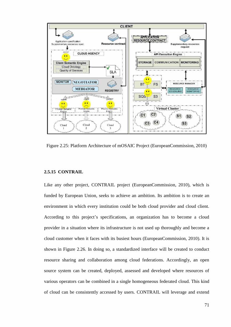
71
Figure 2.25: Platform Architecture of mOSAIC Project (EuropeanCommission, 2010)
2.5.15 CONTRAIL
Like any other project, CONTRAIL project (EuropeanCommission, 2010), which is
funded by European Union, seeks to achieve an ambition. Its ambition is to create an
environment in which every institution could be both cloud provider and cloud client.
According to this project’s specifications, an organization has to become a cloud
provider in a situation where its infrastructure is not used up thoroughly and become a
cloud customer when it faces with its busiest hours (EuropeanCommission, 2010). It is
shown in Figure 2.26. In doing so, a standardized interface will be created to conduct
resource sharing and collaboration among cloud federations. Accordingly, an open
source system can be created, deployed, assessed and developed where resources of
various operators can be combined in a single homogeneous federated cloud. This kind
of cloud can be consistently accessed by users. CONTRAIL will leverage and extend

72
the results of the XtreemOS FP6 project (Kielmann, Pierre, & Morin, 2010), which
builds a Linux-based operating system to support Virtual Organizations for next-
generation clouds. Moreover, it will provide efficient vertical integration of PaaS and
IaaS, QoS integration within infrastructure and comprehensive offering for Cloud
platforms.
Figure 2.26: Integrating Multiple Independent Clouds into a Federated Cloud
(EuropeanCommission, 2010)
2.5.16 Vision Cloud
VISION cloud aims to introduce architecture for a cloud-oriented infrastructure
(Figure 2.27). This architecture is applied to design a reference deployment for novel
technologies and open standards. Then a scheme or framework will emerge which is
able to offer data-centric storage services in an adaptive manner. As a result, data lock-
in problem can be easily resolved and secure or safe data interoperability will be
guaranteed (EuropeanCommission, 2010). The achievement of above-mentioned goal
requires many factors or parameters such as exhaustive data interoperability,

73
computational storage, quality of service and security guarantees, concrete data model
and content-centric access within the whole infrastructure.
Figure 2.27: The VISION Cloud Infrastructure (EuropeanCommission, 2010)
2.5.17 REMICS
The goal of REMICS is to develop advanced model driven methodology and tools for
reuse and migration of legacy applications to interoperable cloud services. Service cloud
paradigm stands for combination of cloud computing and Service Oriented Architecture
(SOA) for development of Software as a Service (SaaS) systems
(EuropeanCommission, 2010; Mohagheghi, Berre, Henry, Barbier, & Sadovykh, 2010).
Hence, the language which REMICS applies must be broadened. It is necessary to
manage particular patterns of architecture and model-based methods in order to transfer

74
architecture and to oversee the specific features of service clouds development
framework (Figure 2.28).
Figure 2.28: Overview of REMICS (EuropeanCommission, 2010)
In fact, REMICS technology requires some additional attributes and factors to formulate
model for cloud architecture. These factors and attributes include model-based service
interoperability, Models@Runtime extensions and PIM4Cloud. Another noticeable
feature of this project is the significance and focus it places on open meta-models even
though it tries to introduce standard frameworks for managing service, cloud
computing, SOA, validation, business models, knowledge discovery and service
interoperability.

75
2.5.18 RESERVOIR
The major goal behind RESERVOIR project is create an innovational service–oriented
infrastructure whose focus is on services. This infrastructure will enhance vigorous
interoperability among cloud providers to offer services as resources in a reliable
manner. Thus, different IT utilities with independent and distinct technologies can be
created. These utilities can be accessed whenever they are needed and they bring about
more sense of competitiveness in the EU economy. In RESERVOIR project,
interoperability is exerted in all architectural layers. The architecture of this project
dictates that cloud providers have to express the requests in a similar language;
therefore, it can bring about inter-operation among them. In doing so, it will be feasible
for service providers to select their favorite RESERVOIR cloud providers in accordance
with their requirements. Consequently, their activities will be more tangible in the
market of cloud provision (Rochwerger et al., 2009).
Figure 2.29: Architecture Proposed by RESERVOIR Project (Rochwerger et al., 2009)

76
Figure 2.29 depicts what constituents are in a RESERVOIR architecture. These
constituents include Virtual Execution Environment Host (VEEH), Virtual Execution
Environment Manager (VEEM) and service manager. The highest level of abstraction is
service manager. The task this constituent responsible for is to communicate with
service providers in order to obtain service manifest, discuss the prices and to conduct
billing. Manifest component gives out information which service manager applies to
assign VEEs and the resources related to it. In fact, service manager communicates with
virtual execution environment manager to assign resources and to offer and employ
service application. Furthermore, application implementation or deployment is observed
and controlled by service manager. It is performed to assure SLA compliance such as
attuning the capacity of applications. The communication between service manager,
virtual execution environment manager, VEE hosts and other VEE managers are
conducted through associated sites. One of the important tasks the host is able to do is
distinguish IT management decisions of service manager and assign them to various
virtualization platforms. In addition, a crucial attribute of VEEHs is that they can
conduct transparent transfer of VEE to every congruent VEEH within a RESERVOIR
cloud (Rochwerger et al., 2009).
2.5.19 SITIO
SITIO focuses on the creation of a framework and an architecture that will ensure the
brokers’accesstobusinessandcloud computing services with a minimum cost. Based
on these, a platform will be developed that will serve as a means to achieve reliable,
secure and cost-efficient interoperability between heterogeneous applications, through
the combination of concepts such as Software as a Service, Semantics, Business Process
Modeling and Cloud Computing (Garcia-Sanchez et al., 2010). Figure 2.30 depicts the
basiccomponentsoftheproject’sarchitecture.

77
Four basic elements are identified by the SITIO architecture, namely user interface,
process services, business services and Metadata services.
The user interface allows different users to access the SITIO platform and use and
manage their accounts and applications. Software developers and IT providers visit the
interface in order to deploy their applications, whereas the end users can search in the
applicationsrepositoryandsubscribetotheonesthey’reinterestedin.
The process and business services layers provide the ability to run arbitrary web
services in the cloud computing platform. To this end, distribution, load balancing and
data persistence services are added to a given application transparently. However, to
ensure this functionality, some restrictions on the services that run on top of the
platform have to be imposed (e.g. specifying the programming language the application
should be built on).
The distribution of an application is ensured by uploading it on one of the cluster’s
synchronized application servers.
The metadata services layer uses ontologies for the semantic description of the available
services. The annotators of the services are the web services developers themselves,
since they fully comprehend the methods of the services they develop (Garcia-Sanchez
et al., 2010).

78
Figure 2.30: Architecture Proposed by SITIO (Garcia-Sanchez et al., 2010)
2.5.20 NEXOF
The NEXOF Reference Architecture is an open, coherent, consistent and comprehensive
set of concepts and specifications. It can be used as a prototype for system architects to
design architectures of service-based software systems which, in turn, provide solutions
to a well defined set of requirements (Figure 2.31). Its main goal is to combine selected
innovations in the area of service oriented architectures and technologies to facilitate the
implementations of interoperable service environments (NEXOFRA, 2010).
The NEXOF Reference Architecture consists of the following main elements:
Architectural Guidelines and Principles that include principles underlying the
construction of the framework as well as the set of reference properties
associated with each of the components and patterns in the reference
architecture. Furthermore, guidelines for the instantiation of a specific system
architecture according to its requirements are incorporated

79
The reference model that depicts the key entities that establish service-based
systems as well as the relationships between them
The Glossary that defines the terms used across the reference architecture
The Reference Specifications that consist of the following elements:
o Pattern Ensemble that describes the different ways in which functionalities
can be achieved by associating components and other patterns
o Standards Catalogue that describes the standards referred to in the reference
architecture
o Components Catalogue that groups both, abstract descriptions of
components as well as product or software-based components
Figure 2.31: NEXOF Reference Architecture (NEXOFRA, 2010)

80
2.5.21 Cloud@Home
French national agency funded and launched a project called Cloud@Home. The goal
of this project is to design heterogeneous hardware for congruent clouds. The most
important goal this project tries to achieve is to create a cloud infrastructure which is
able to distribute services and resources within the cloud appropriately. One of the other
goals this project seeks to attain is the creation of commercial clouds which can be used
as the foundation of an open market. In this kind of market, users are allowed to trade or
exchange services in a pay-per-use manner (Cunsolo, Distefano, Puliafito, & Scarpa,
2009). Therefore, it seems necessary to scrutinize the fundamental architecture which
Cloud@Home project presents. Figure 2.32 depicts this architecture and its system
configurations are shown in Figure 2.33. The responsibility of fronted layer is to
manage services and resources via a universal cloud system approach. End-users’ needs
are converted into physical resources requests through this layer. Other functions are
also performed in this layer, including monitoring, negotiation and adjustment of SLAs
in commercial clouds. In doing so, interoperability can be achieved among clouds and
dependability or reliability and availability of services can be examined. It will also
become possible to demand more resources and services from other clouds if any need
emerges. Figure 2.32 illustrates three different methods which cloud can be accessed.
These methods include low level web interface, web 2.0 user interface, and
cloud@home fronted client (directly specifying REST or SOAP queries).
As it is easily understandable from its name, the responsibility of virtual layer is to
virtualize physical resources. When this task is properly accomplished, it will enable
end-users to access a homogeneous view about cloud services and resources. Virtual
layer supplies different tools for fronted layer, one of which is execution service. Design
and management of VMs is done in this layer (e.g. Migration, replication). An end-user
considers it as a set of VMs. Another tool which virtual layer offers is storage service.

81
An end-user may regard it as a remote disk. The storage system will be spread out
among cloud storage hardware resources.
Virtual layer receives physical resources from physical layer which are needed to
deploy storage and execution services. Physical layer also prepares tools and
frameworks required to manage resources in a local domain.
Figure 2.32: Basic Architecture of Cloud@Home Project (Cunsolo et al., 2009)
Figure 2.33: Configuration of Cloud@Home System (Cunsolo et al., 2009)
82
2.5.22 SOA4All
SOA4All project is a novel project whose goal is to create an environment in which
services can be released and applied by many parties. A sophisticated web technology
should be created to achieve this goal. The designers and developers of this project try
to create an exhaustive structure which can combine complemental and evolutionary
technical innovations into a service provisioning platform with consistent and
independent domain (Figure 2.34) (Krummenacher, Norton, Simperl, & Pedrinaci,
2009).
A thoroughly web-based user front-end is offered by SOA4All studio. This studio is
able to build, offer, utilize and analyze the services which are distributed in SOA4All.
There are three sub-components in this architecture which are responsible for
performing three different tasks related to service management. These three tasks
include analysis at runtime, provisioning at design time, and consumption.
SOA4All architecture is built upon an infrastructural cornerstone called SOA4All
distributed service bus. It connects and integrates all the SOA4All components and
makes them cooperate with one another via integrating semantic spaces and enterprise
service bus.
In addition, this architecture possesses SOA4All platform services which make up a
collection of services offering wide range of tasks and activities. These tasks and
activities encompass service execution, service discovery, reasoning engine, service
ranking and selection, service composition and service adaptation.
Ultimate users can prepare business services (3rd party web services and light-weight
processes). These services are the true service they are able to provide. The major goal
SOA4All framework seeks to accomplish is that it wants to be a technology agnostic
and less intrusive as much as possible.
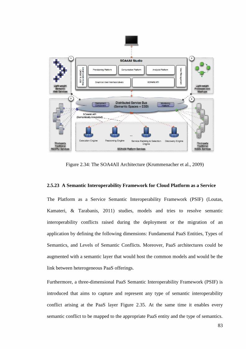
83
Figure 2.34: The SOA4All Architecture (Krummenacher et al., 2009)
2.5.23 A Semantic Interoperability Framework for Cloud Platform as a Service
The Platform as a Service Semantic Interoperability Framework (PSIF) (Loutas,
Kamateri, & Tarabanis, 2011) studies, models and tries to resolve semantic
interoperability conflicts raised during the deployment or the migration of an
application by defining the following dimensions: Fundamental PaaS Entities, Types of
Semantics, and Levels of Semantic Conflicts. Moreover, PaaS architectures could be
augmented with a semantic layer that would host the common models and would be the
link between heterogeneous PaaS offerings.
Furthermore, a three-dimensional PaaS Semantic Interoperability Framework (PSIF) is
introduced that aims to capture and represent any type of semantic interoperability
conflict arising at the PaaS layer Figure 2.35. At the same time it enables every
semantic conflict to be mapped to the appropriate PaaS entity and the type of semantics.

84
The PSIF have been implemented by Cloud4SOA project (Loutas et al., 2010) to
resolve the semantic incompatibilities arisen both within the same as well as across
different Cloud PaaS systems and enable Cloud-based application development,
deployment and migration across heterogeneous PaaS offerings. In particular, PSIF is
structured according to the following core dimensions:
Fundamental PaaS Entities, i.e. PaaS system, PaaS offering, management
interface, software component, IaaS system and application.
Types of Semantics, i.e. functional, non-functional and execution.
Levels of Semantic Conflicts, i.e. information model and data.
A semantic interoperability conflict is raised when during the deployment of an
application on a PaaS offering, or during the migration of an application from one PaaS
offering to another, the semantic models of any of the fundamental PaaS entities are
incompatible. A semantic interoperability conflict may also be raised when two
different PaaS systems try to exchange information.
The first dimension (i.e. Fundamental PaaS Entities) allows us to locate where a
semantic conflict is raised, i.e. between which fundamental entities. The second
dimension (i.e. Types of Semantics) allows us to identify the type of the semantic
conflict that has occurred. Finally, the third dimension (i.e. Levels of Semantic
Conflicts) allows us to identify the nature of the semantic conflict that has occurred.
Information about all three dimensions needs to be collected in order to concretely
define, fully understand and effectively treat a specific semantic conflict.

85
Levels of Semantic
Conflicts
Fundamental PaaS Entities
PaaS Offering
PaaS System
Da
ta L
ev
el
Types of Semantics
Info
rma
tion
-mo
de
l
Le
ve
l Management Interface
Software Component
Application
IaaS System
Functional
Execution
Non-functional
Figure 2.35: The PaaS Semantic Interoperability Framework (PSIF)
2.5.24 NEGOSEIO: A framework for negotiations toward Sustainable Enterprise
Interoperability
The best way to have a strong interoperable environment is to perform constant,
periodic maintenance operations in order to adapt enterprises to their surrounding
ecosystem. NEGOSEIO framework (Figure 2.36) promotes continuous improvement
and adaptation towards the management of interoperability on enterprise systems, and
which has negotiations as a core mechanism to handle inconsistencies and solutions for
the detected interoperability problems (Coutinho et al., 2012). Following this approach,
enterprises shall become more adaptable to changes and external factors, consequently
developing resilient and efficient interactions with its supply chain. The framework is
validated with its application in a real business case of aerospace mission design on the
European Space Agency (ESA).

86
Figure 2.36: The NEGOSEIO framework architecture, applied to the ESA-CDF
2.5.25 PaaS Manager: A Platform-as-a-Service Aggregation Framework
Figure 2.37 presents the PaaS Manager logical architecture and the integrating modules
which support the defined operational processes (Cunha, Neves, & Sousa, 2014). The
PaaS Manager architecture has a modular design that allows the entire system to
remains fully operational even if some vendor or monitoring API is not operating
correctly. Consequently, each API has been implemented by distinct modules and
managed by single entities. Finally, a REST interface exposes the specified operations
to be invoked by any HTTP client application.

87
Figure 2.37: PaaS Manager Architecture
2.6 Discussion and Findings
This section presents a comprehensive analysis and discussion of cloud computing
interoperability frameworks and models. In the reviewed literature there are several
attempts to scope, address and define interoperability in cloud computing. As mentioned
in section 2.4.2, interoperability is divided into infrastructure as a service, platform as a
service, and software as a service levels. (Figure 2.10). Table 2.1 classifies the
interoperability models based on their focus in cloud computing environments.

88
Table 2.1: Cloud Computing Interoperability Models
Cloud Computing
Interoperability Models
Infrastructure as
a Service
Platform as
a Service
Software as
a Service
Aneka
(Vecchiola et al., 2009) × √
×
Cloud Exchange Federated
Cloud
(Buyya et al., 2010) √ ×
×
Open Platform as a Service
(RedHat, 2010)
× √ ×
Red Hat Reference Cloud
Computing Architecture
(RedHat, 2009)
× √ ×
Cisco Reference Cloud
Computing Architecture
(Cisco, 2009)
× √ ×
IBM Reference Cloud
Computing Architecture
(Dodani, 2009) √
√ √
Cloud Development Stack
Model
(SaugatuckTechnology, 2010)
× √ ×
Next Generation Cloud
Architecture
(Sarathy et al., 2010)
× √ ×
Elastra Cloud Computing
Reference Architecture
(Charlton, 2009)
× √ ×
Cloud Computing Reference
Model
(Marks & Lozano, 2010) √
√ √
Cloud Computing Model
(Sambyal et al., 2010)
× √ ×
Adaptive Platform as a Service
Architecture
(Rymer, 2010)
× √ ×
Cloud Deployment Model
(Charlton, 2009)
× √ ×
mOSAIC
(EuropeanCommission, 2010) √
× ×
CONTRAIL
(EuropeanCommission, 2010) √ √
×
Vision Cloud
(EuropeanCommission, 2010) √
× ×

89
Cloud Computing
Interoperability Models
Infrastructure as
a Service
Platform as
a Service
Software as
a Service
REMICS
(Mohagheghi et al., 2010) ×
× √
RESERVOIR
(Rochwerger et al., 2009) √
× ×
SITIO
(Garcia-Sanchez et al., 2010)
× × √
NEXOF
(Garcia-Sanchez et al., 2010)
× × ×
Cloud@Home
(Cunsolo et al., 2009) √
× ×
SOA4All
(Cunsolo et al., 2009) ×
× ×
A Semantic Interoperability
Framework for Cloud Platform
as a Service
(Loutas, Kamateri, & Tarabanis,
2011)
× √ ×
NEGOSEIO: A framework for
negotiations toward Sustainable
Enterprise Interoperability
(Cretan et al., 2012)
× × ×
PaaS Manager: A Platform-as-a-
Service Aggregation Framework
(Cunha et al., 2014)
× √ ×
As shown in Table 2.1, It is observed that most of the existing models and frameworks
on cloud computing interoperability emphasizes on the infrastructure as a service and
platform as a service level (Foster, 2009). Interoperability research in the software as a
service is still very immature. In the near future interoperability models are expected to
emerge for software as a service level.
Table 2.2 classifies the interoperability models and frameworks for software as a service
systems in cloud computing environments based on syntactic interoperability and
semantic interoperability.

90
Table 2.2: Interoperability Models for Software as a Service Systems in Cloud
Computing Environments
Cloud Software as a Service
Systems Interoperability Models
Syntactic
Interoperability
Semantic
Interoperability
IBM Reference Cloud Computing
Architecture (Dodani, 2009) √
×
Cloud Computing Reference Model
(Marks & Lozano, 2010) √
×
REMICS
(Mohagheghi et al., 2010) × √
SITIO
(Garcia-Sanchez et al., 2010) × √
As shown in Table 2.2, very few existing interoperability models for software as a
service systems in cloud computing environments focuses on semantic interoperability.
In fact, the main objectives of semantic interoperability are dynamic service discovery
and dynamic service invocation. Thus, a comprehensive semantic interoperability
framework for software as a service systems in cloud computing environments must
cover dynamic service discovery and service invocation. Literature review shows that
REMICS and SITIO focus only one of the two semantic interoperability objectives.
Therefore, a comprehensive semantic interoperability framework for software as a
service systems in cloud computing environments that cover dynamic service discovery
and dynamic service invocation is required.
The need for a semantic interoperability model or framework for software as a service
systems in cloud computing environments is evident in the number of recent papers
(Dodani, 2009; Garcia-Sanchez et al., 2010; Marks & Lozano, 2010; Mohagheghi et al.,
2010). In fact, the semantic interoperability framework’s objective for software as a
service systems in cloud computing environments is to support dynamic service
discovery and service invocation. We have illustrated many academically researched

91
systems that provide useful insight into the individual components of our framework on
a micro level.
We therefore focus our framework on making it as a semantic interoperability
framework for software as a service systems in cloud computing environments. We
designed our framework to help autonomous software as a service systems to interact
and communicate with each other. The proposed semantic interoperability framework
for software as a service systems in cloud computing environments is used as a
middleware connecting software as a service systems together without them having to
directly communicating with each other. The proposed semantic interoperability
framework for software as a service systems in cloud computing environments has
reference to services exposed by each software as a service system and mediates the
dynamic discovery and invocation of these services for other software as a service
systems.
2.7 Summary
In Section 2.2, we studied the existing literature on cloud computing focusing on cloud
computing definitions, cloud computing deployment models, cloud computing service
models, cloud computing essential characteristics, cloud computing actors, relationships
between cloud computing actors, and driver and barriers for cloud computing adoption.
In Section 2.3, we started by reviewing existing definitions for interoperability. While
providing a good understanding of the interoperability, they come shortly to provide
insights on the different dimensions of interoperability, e.g. syntactic and semantic
interoperability. Therefore, the need for a comprehensive and more detailed definition
of interoperability and approaches to achieving interoperability emerges.

92
Section 2.4 presents an overview of cloud computing interoperability. It focuses on
cloud computing interoperability types and definitions that capture the key distinction
between interoperability and portability in cloud computing.
Section 2.5 presents the related work in cloud computing interoperability. We started
by reviewing existing interoperability models and frameworks. The models and
frameworks are organized based on their focus. A survey of the literature shows that
most of the existing interoperability models and frameworks emphasize on the
infrastructure as a service and platform as a service in cloud computing environments.
Finally, the characteristics, strengths, and weaknesses of cloud computing
interoperability models and frameworks were compared and discussed in Section 2.6. It
concludes that the interoperability models and frameworks for software as a service
systems in cloud computing environments is still very immature.

93
3.0 RESEARCH METHODOLOGY
3.1 Introduction
This chapter describes the methodology applied in this research. As Figure 3.1 shows,
this research is accomplished through a number of steps. It begins with a study on
related works in the literature. Then, problem statement and research objectives are
explained. In the next step, semantic interoperability requirements for software as a
service systems in cloud computing environments that are needed to support are
analyzed. The details of the proposed semantic interoperability framework for software
as a service systems in cloud computing environments are presented. It includes the
design and implementation of the proposed semantic interoperability framework.
Finally, the evaluation methods of the semantic interoperability framework are
elaborated.
Figure 3.1: Research Methodology

94
3.2 Conducting Literature Review
Chapter 2 presents a background study and extensive literature review about the
overview of cloud computing, interoperability, cloud computing interoperability, and
interoperability frameworks and models in cloud computing environments. Most of
them have been collected from books, journals, articles, conference proceedings,
websites, and also from online databases such as Association for Computing Machinery
(ACM) and IEEE online publication. An analysis of the features of the various
interoperability frameworks and models in cloud computing environments was carried
out based on information gathered from the literature review. The results from the
analysis give a better understanding and more accurate perspective of the current issues
and developments in interoperability frameworks in cloud computing environments.
Furthermore, the strengths and weaknesses of available interoperability frameworks and
models have been considered. This information also provides direction for this research,
and aids in formulating the problem statement and research objectives.
3.3 Cloud Software as a Service Systems Semantic Interoperability Analysis
As mentioned in Chapter 2, a generic framework specifically developed for supporting
semantic interoperability of software as a service systems in cloud computing
environments is lacking in the literature. In fact, Chapter 2 describes various
interoperability frameworks, models, and challenges of interoperability specifically for
software as a service systems at semantic level in cloud computing environments. To
achieve the first objective (to investigate, and analysis the semantic interoperability
requirements for software as a service systems in cloud computing environments), and
in order to overcome the semantic interoperability challenges in software as a service
systems, we need to identify the main semantic interoperability requirements for

95
software as a service systems in cloud computing environments. We call this course of
action Cloud Software as a Service Systems Semantic Interoperability Analysis. In fact,
cloud software as a service systems semantic interoperability analysis is part of our
proposed framework and it can be considered as the preliminary step in developing the
semantic interoperability framework for software as a service systems in cloud
computing environments.
Syntactic and semantic interoperability requirements of software as a service systems in
cloud computing environments are fully analyzed and studied. In interoperability of
software as a service systems in cloud computing environments, the first problem is the
number of cloud software as a service providers from the viewpoint of cloud software as
a service consumers. Interoperability of cloud software as a service consumers with all
cloud software as a service providers for finding the required services is practically
impossible due to their large number (Figure 3.3). Therefore, one should use cloud
broker in order to solve this problem.
Figure 3.2: Too Many Cloud Software as a Service Providers

96
The next problem of cloud software as a service consumers for direct interoperability
with cloud software as a service providers is the large number of application
programming interfaces. Any cloud software as a service provider has special
application programming interfaces and consumers should be able to establish
relationship with different application programming interfaces (Figure 3.3). In order to
solve this problem, a single application programming interface should be defined to
realize interoperability and cloud software as a service consumers use this single
application programming interface instead different application programming interfaces.
Figure 3.3: Cloud Software as a Service Providers with Different APIs
3.3.1 Cloud Software as a Service Systems Interoperability Scenarios
We have identified three major interoperability scenarios for Software as a service
systems in cloud computing Environments as discussed below.

97
3.3.1.1 Interoperability of Software as a Service Systems within a Cloud
Two different software as a service systems are hosted in a cloud (Figure 3.4).
Interoperability enables these software as a service systems to talk to each other. The
possible sub-scenarios include these software as a service systems can be owned by two
different companies.
Figure 3.4: Interoperability of Software as a Service Systems within a Cloud
3.3.1.2 Interoperability of Software as a Service Systems in Homogeneous Clouds
As shown in Figure 3.5, two software as a service systems that interact with each other,
may be from two different clouds but the same kind.
Figure 3.5: Interoperability of Software as a Service Systems in Homogeneous Clouds

98
3.3.1.3 Interoperability of Software as a Service Systems in Heterogeneous
Clouds
One software as a service system is in public cloud and the other software as a service
system is in private cloud. As described above, this is the currently dominating scene
for cloud interoperability. The first two scenarios will become dominant when there are
some commercial clouds and cloud services become pervasive (see Figure 3.6).
Figure 3.6: Interoperability of Software as a Service Systems in Heterogeneous Clouds
3.3.2 Syntactic Interoperability of Software as a Service Systems in Cloud
Computing Environments
Syntactic interoperability between software as a service systems in cloud computing
environments describes what a software as a service system can do, where it resides,
and how to invoke it. It does not deal with meaning and interpretation of data and
operations. In syntactic interoperability, discovery, and invocation of software as a
service systems are done at design time. In syntactic interoperability, developers have to
obtain the semantics of a software as a service before it is actually used. Therefore, in
syntactic interoperability, software as a service system discovery, and invocation are
done in a static manner at design time (Figure 3.7) (Lewis & Wrage, 2006).
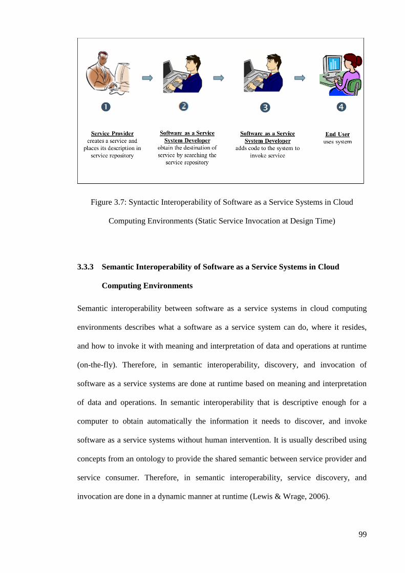
99
Figure 3.7: Syntactic Interoperability of Software as a Service Systems in Cloud
Computing Environments (Static Service Invocation at Design Time)
3.3.3 Semantic Interoperability of Software as a Service Systems in Cloud
Computing Environments
Semantic interoperability between software as a service systems in cloud computing
environments describes what a software as a service system can do, where it resides,
and how to invoke it with meaning and interpretation of data and operations at runtime
(on-the-fly). Therefore, in semantic interoperability, discovery, and invocation of
software as a service systems are done at runtime based on meaning and interpretation
of data and operations. In semantic interoperability that is descriptive enough for a
computer to obtain automatically the information it needs to discover, and invoke
software as a service systems without human intervention. It is usually described using
concepts from an ontology to provide the shared semantic between service provider and
service consumer. Therefore, in semantic interoperability, service discovery, and
invocation are done in a dynamic manner at runtime (Lewis & Wrage, 2006).

100
In addition to, software as a service systems are constantly being added and removed.
What would happen if a software as a service system required by a system were
removed from the environment or had its interface changed? What if a new and better
software as a service system were introduced that a system might be able to utilize?
The discovery, and invocation of services at runtime is one potential solution to this
problem. The ontology for service can describe the properties and capabilities of
software as a service systems in such a way that the descriptions can be interpreted by a
computer system in an automated manner. Therefore, in semantic interoperability,
service discovery, and invocation are done in a dynamic manner at runtime (Figure 3.8).
Figure 3.8: Semantic Interoperability of Software as a Service Systems in Cloud
Computing Environments (Dynamic Service Invocation at Run Time)

101
3.4 Cloud Software as a Service Systems Semantic Interoperability Framework
Design
In order to establish semantic interoperability between cloud software systems as a
service systems and to cover interoperability requirements, there is need for an semantic
interoperability framework.
In order to propose and develop a semantic interoperability framework for software as a
service systems in cloud computing environments and To achieve the second research
objective, the first step is framework design. In the framework design stage, the design
of architecture of semantic interoperability framework for software as a service systems
in cloud computing environments is required (Figure 3.9). The framework design stage
also involves the design of actors and components in the semantic interoperability
framework for software as a service systems in cloud computing environments.
Figure 3.9: Cloud Software as a Service Systems Semantic Interoperability Framework
Design
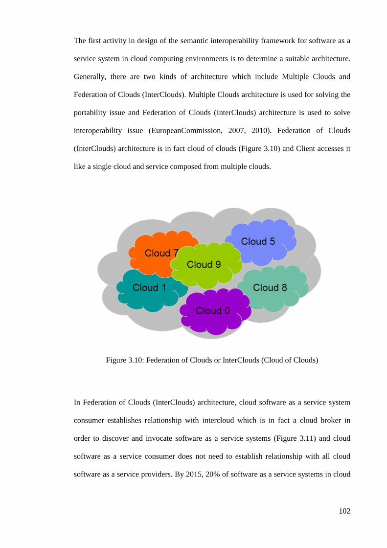
102
The first activity in design of the semantic interoperability framework for software as a
service system in cloud computing environments is to determine a suitable architecture.
Generally, there are two kinds of architecture which include Multiple Clouds and
Federation of Clouds (InterClouds). Multiple Clouds architecture is used for solving the
portability issue and Federation of Clouds (InterClouds) architecture is used to solve
interoperability issue (EuropeanCommission, 2007, 2010). Federation of Clouds
(InterClouds) architecture is in fact cloud of clouds (Figure 3.10) and Client accesses it
like a single cloud and service composed from multiple clouds.
Figure 3.10: Federation of Clouds or InterClouds (Cloud of Clouds)
In Federation of Clouds (InterClouds) architecture, cloud software as a service system
consumer establishes relationship with intercloud which is in fact a cloud broker in
order to discover and invocate software as a service systems (Figure 3.11) and cloud
software as a service consumer does not need to establish relationship with all cloud
software as a service providers. By 2015, 20% of software as a service systems in cloud

103
computing environments will be intermediated by interclouds (cloud brokers) (Smith,
2011).
Figure 3.11: Federation of Clouds (InterClouds)

104
The literature review of related interoperability frameworks for software as a service
systems in cloud computing environments allows us to identify the main cloud
computing interoperability actors (Table 3.1).
Table 3.1: Actors in Interoperability Frameworks for Software as a Service Systems in
Cloud Computing Environments
Cloud Software as a Service Systems
Interoperability Frameworks Interoperability Actors
IBM Reference Cloud Computing
Architecture
(Dodani, 2009)
End Users/Service Consumers
Application Developers
Service providers
Cloud Computing Reference Model
(Marks & Lozano, 2010)
Cloud Providers
Consumers
Intermediaries
REMICS
(Mohagheghi et al., 2010)
Service Providers
Service Developers
Service Consumers
SITIO
(Garcia-Sanchez et al., 2010)
End Users
IT Providers
Software Developers
As presented in Table 3.1, we draw upon this analysis and identify the main actors,
namely Cloud Software as a Service Provider, Cloud Broker and Cloud Software as a
Service Consumer. Table 3.2 illustrates the mapping between interoperability actors and
clod computing actors.
Table 3.2: Interoperability Actors and Cloud Computing Actors Mapping
Interoperability Actors Cloud Computing Actors
Application Developers
Service Providers
IT Providers
Software Developers
Cloud Providers
Service Developers
Cloud Software as a Service
Provider
Intermediaries Cloud Broker
Consumers
End Users/Service Consumers
Cloud Software as a Service
Consumer
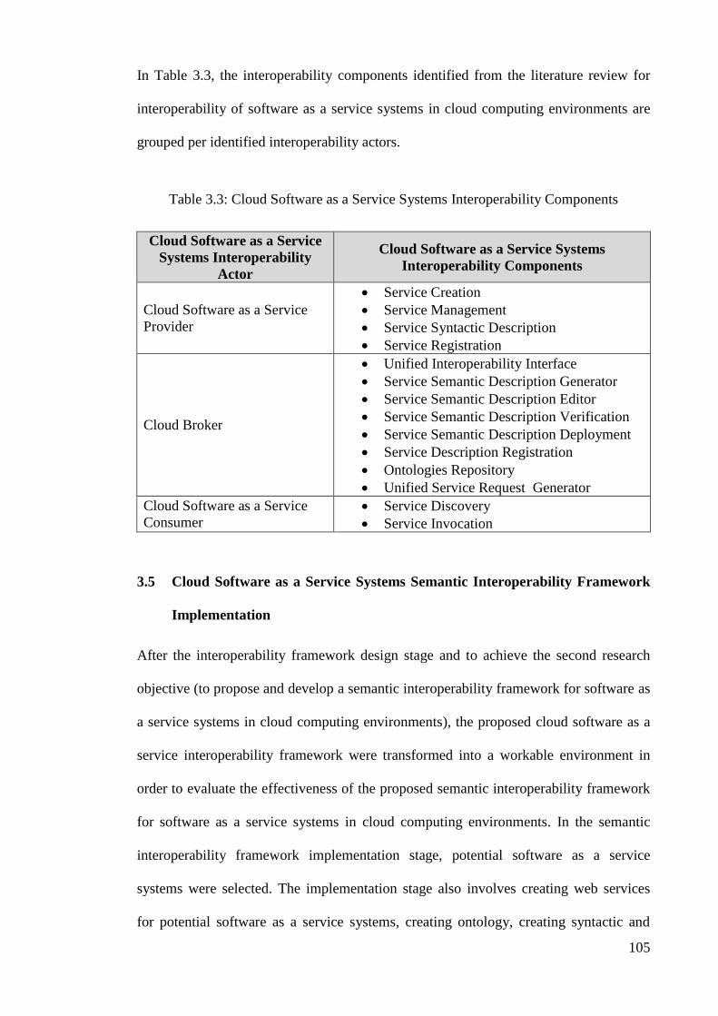
105
In Table 3.3, the interoperability components identified from the literature review for
interoperability of software as a service systems in cloud computing environments are
grouped per identified interoperability actors.
Table 3.3: Cloud Software as a Service Systems Interoperability Components
Cloud Software as a Service
Systems Interoperability
Actor
Cloud Software as a Service Systems
Interoperability Components
Cloud Software as a Service
Provider
Service Creation
Service Management
Service Syntactic Description
Service Registration
Cloud Broker
Unified Interoperability Interface
Service Semantic Description Generator
Service Semantic Description Editor
Service Semantic Description Verification
Service Semantic Description Deployment
Service Description Registration
Ontologies Repository
Unified Service Request Generator
Cloud Software as a Service
Consumer
Service Discovery
Service Invocation
3.5 Cloud Software as a Service Systems Semantic Interoperability Framework
Implementation
After the interoperability framework design stage and to achieve the second research
objective (to propose and develop a semantic interoperability framework for software as
a service systems in cloud computing environments), the proposed cloud software as a
service interoperability framework were transformed into a workable environment in
order to evaluate the effectiveness of the proposed semantic interoperability framework
for software as a service systems in cloud computing environments. In the semantic
interoperability framework implementation stage, potential software as a service
systems were selected. The implementation stage also involves creating web services
for potential software as a service systems, creating ontology, creating syntactic and

106
semantic descriptions for the selected services, publishing the semantic service
description, register the service in the intermediary, and discover and invoke the
services.
3.6 Cloud Software as a Service Systems Semantic Interoperability Framework
Evaluation
To achieve the third objective (to evaluate the capability of the proposed semantic
interoperability framework for software as a service systems in cloud computing
environments), After finishing the implementation stage, important parts of the
semantic interoperability framework for software as a service systems in cloud
computing environments were evaluated to ensure semantic interoperability
requirements are met. Considering that there is no comprehensive framework for
semantic interoperability of software as a service systems in cloud computing
environments, which is comparable to the framework provided for semantic
interoperability of cloud software as a service systems, therefore, the effectiveness of
the provided framework has been compared and studied with the case which the cloud
broker does not act as middleware for semantic interoperability of cloud software as a
service systems.
To evaluate the effectiveness of the proposed semantic interoperability framework for
software as a service systems in cloud computing environments, performance measures
were used. The performance measures are concerned with the exchange of information
and use information exchanged (Daclin, Chen, & Vallespir, 2006). The performance
measures are interoperability time, interoperability quality, interoperability cost, and
conformity. Interoperability time is defined as the time when there is interoperability
between cloud software as a service providers and cloud software as a service consumer

107
and interoperability is completed (Daclin et al., 2006). Interoperability time is measured
separately for the two defined scenarios, using 10 cloud software as a service provider
number. The ratio of successful interoperability to total number of interoperability is
called interoperability quality (Daclin et al., 2006). Interoperability quality is measured
separately for the two defined scenarios, using 500 cloud software as a service request
number. Interoperability cost is the cost (number of service request and response) spent
for performing interoperability action between service provider and service consumer
(Daclin et al., 2006). Interoperability cost is measured separately for the two defined
scenarios, using 100 cloud software as a service provider number. Conformity relates to
the extent to which the exchanged information in interoperability process is used. Ratio
of information received conforming to the information requested in interoperability
process is called conformity. Conformity is measured separately for the two defined
scenarios, using 10 cloud software as a service number.
3.7 Summary
This chapter discussed the methodology adopted for this research. A research
methodology was proposed as an approach to achieve the research objectives. The
details regarding the procedures involved in the proposed research methodology are
explained according to the following sequence: Cloud Software as a Service Systems
Semantic Interoperability Analysis, Cloud Software as a Service Systems Semantic
Interoperability Framework Design, Cloud Software as a Service Systems Semantic
Interoperability Framework Implementation, and Software as a Service Systems
Semantic Interoperability Framework Evaluation. The software as a service semantic
interoperability requirements, actors, and components used in the framework
development phases have been explained in detail. The next chapter presents the design

108
of the semantic interoperability framework for software as a service systems in cloud
computing environments.

109
4.0 DESIGN OF SEMANTIC INTEROPERABILITY FRAMEWORK
FOR SOFTWARE AS A SERVICE SYSTEMS IN CLOUD
COMPUTING ENVIRONMENTS
4.1 Introduction
This chapter presents the design of the semantic interoperability framework for software
as a service systems in cloud computing environments in detail. The activities involved
in establishing a semantic interoperability framework for software as a service systems
in cloud computing have designed. The semantic interoperability framework for
software as a service systems in cloud computing environments in high level, define
actors, the interactions among the actors, and components. This chapter also describes
the architecture of the semantic interoperability framework for software as a service
systems in cloud computing environments.

110
4.2 The Semantic Interoperability Framework for Software as a Service Systems
in Cloud Computing Environments: An Overview
Figure 4.1 presents an overview of the semantic interoperability framework for software
as a service systems, which identifies the major actors, their activities and components
in cloud computing environments. The diagram depicts a generic high level of semantic
interoperability framework and is intended to facilitate the understanding of the
requirements for semantic interoperability of software as a service systems in cloud
computing environments.
Figure 4.1: The Semantic Interoperability Framework for Software as a Service Systems
in Cloud Computing Environments: An Overview

111
In the proposed semantic interoperability framework for software as a service systems
in cloud computing environments, Service Syntactic Description and Service
Registration components in the Software as a Service Provider actor, and Unified
Interoperability Interface, Semantic Interoperability Layer, Service Description
Registration, and Unified Service Request Generator components in the Cloud Broker
actor are defined. Table 4.1 illustrates mapping between cloud software as a service
systems semantic interoperability requirements and the proposed semantic
interoperability framework for software as a service systems in cloud computing
environments.
Table 4.1: Mapping between Cloud Interoperability Requirements and the Semantic
Interoperability Framework
Cloud Software as a Service Systems
Semantic Interoperability Requirements
The Proposed Semantic Interoperability
Framework for Software as a Service
Systems in Cloud Computing
Environments
Syntactic Interoperability Service Syntactic Description
Service Registration
Single Application Programming
Interface (API) Unified Interoperability Interface
Semantic Interoperability
Semantic Interoperability Layer
Service Semantic Description Deployment
Service Description Registration
Ontologies Repository
Service Discovery Unified Service Request Generator
Intermediary
Service Invocation Mediator
The actors, activities, and components of the semantic interoperability framework are
discussed in the remainder of this chapter. The details of the architecture elements of the
semantic interoperability framework for software as a service systems in cloud
computing environments are discussed in Section 4.5.

112
4.3 Actors in the Semantic Interoperability Framework for Software as a Service
Systems in Cloud Computing Environments
As shown in Figure 4.1, the semantic interoperability framework for software as a
service systems in cloud computing environments defines three major actors: Cloud
Software as a Service Provider, Cloud Broker, and Cloud Software as a Service
Consumer. Each actor is an entity (a person or an organization) that participates and
performs tasks in the semantic interoperability framework for software as a service
systems in cloud computing environments.
4.3.1 Cloud Software as a Service Provider
Cloud Software as a Service Provider deploys, configures, maintains and updates the
operation of the software as a service systems on a cloud infrastructure so that the
services are provisioned at the expected service levels to cloud software as a service
systems consumers. The provider of software as a service assumes most of the
responsibilities in managing and controlling the systems and the infrastructure, while
the cloud software as a service consumers have limited administrative control of the
systems. In the semantic interoperability framework for software as a service systems,
activities of cloud software as a service provider can be described in four major areas.
As shown in Figure 4.1, a cloud software as a service provider conducts its activities in
the areas of service creation, cloud management, service syntactic description, and
service registration. The details are discussed in Section 4.4.1.
4.3.2 Cloud Broker
The cloud broker is the heart of the semantic interoperability framework for software as
a service systems in cloud computing environments. As cloud computing evolves, the

113
integration of cloud services can be too complex for cloud software as a service
consumers to manage. A cloud software as a service consumer may request cloud
software as a service systems from a cloud broker, instead of contacting a cloud
software as a service provider directly. A cloud broker is an entity that manages the use,
performance and delivery of cloud services and negotiates relationships between cloud
software as a service providers and cloud software as a service consumers. In general, a
cloud broker can provide software as a services in three categories (Liu et al., 2011):
Service Intermediation: A cloud broker enhances a given service by improving
some specific capability and providing value-added services to cloud software as
a service consumers. The improvements include managing access to cloud
services, identity management, performance reporting, enhanced security, etc.
Service Aggregation: A cloud broker combines and integrates multiple services
into one or more new services. The broker provides data integration and ensures
the secure data movement between the cloud software as a service consumer and
multiple cloud software as a service providers.
Service Arbitrage: Service arbitrage is similar to service aggregation except
that the services being aggregated are not fixed. Service arbitrage means a
broker has the flexibility to choose services from multiple agencies. The cloud
broker, for example, can use a credit-scoring service to measure and select an
agency with the best score.
In the semantic interoperability framework for software as a service systems, activities
of cloud broker can be described in eight major areas. As shown in Figure 4.2, a cloud
broker conducts its activities in the areas of unified interoperability interface, semantic
interoperability layer, semantic description deployment, service registration, ontology

114
repository, unified service request creation, mediator, and intermediary. The details are
discussed in Section 4.4.1.
Figure 4.2: Cloud Broker - Major Components
4.3.3 Cloud Software as a Service Consumer
Software as a service systems in the cloud are made accessible via a network to the
cloud software as a service consumers. The consumers of the systems can be
organizations that provide their members with access to software as a service systems,
end users who directly use software as a service systems, or software as a service
system administrators who configure applications for end users. Software as a service
consumers can be billed based on the number of end users, the time of use, the network
bandwidth consumed, the amount of data stored or duration of stored data.
In the semantic interoperability framework for software as a service systems, activities
of cloud software as a service consumers can be described in two major areas. As shown
in Figure 4.1, a cloud software as a service consumer conducts its activities in the areas
of service discovery and service invocation. The details are discussed in Section 4.4.1.

115
4.3.4 Relationships between Actors in the Semantic Interoperability Framework
for Software as a Service in Cloud Computing Environments
In the semantic interoperability framework for software as a service systems in cloud
computing environments, a cloud software as a service consumer request services from
a cloud broker instead of contacting a cloud software as a service provider directly. The
cloud broker creates a new service by combining multiple services or by enhancing an
existing service. In this way, the actual cloud software as a service providers are
invisible to the cloud software as a service consumer and the cloud software as a service
consumer interacts directly with the cloud broker (Figure 4.3).
Figure 4.3: Relationships between Actors in the Semantic Interoperability Framework
for Software as a Service Systems in Cloud Computing Environments
With this relationship between actors in the semantic interoperability framework for
software as a service systems in cloud computing environments, the cloud software as a

116
service provider and the cloud software as a service consumer do not need to know each
other, and a single API through broker enhances interoperability.
4.4 Components in the Semantic Interoperability Framework for Software as a
Service Systems in Cloud Computing Environments
This section describes more details about the components in the semantic
interoperability framework for software as a service systems in cloud computing
environments. The design of the components is classified according to the actors in each
component.
4.4.1 Cloud Software as a Service Provider Component
Figure 4.4 shows the use case for cloud software as a service provider. The Details of
cloud software as a service provider components are described in the next sections.
Figure 4.4: Use Case for Cloud Software as a Service Provider

117
4.4.1.1 Service Creation
For the development of a semantic interoperability framework for software as a service
systems, the first step is creating a service interface for each of existing software as a
service system. A software as a service system interface is an adapter that allows a
software as a service system to communicate with other software as a service systems in
cloud computing environments. In a service oriented architecture environment, a web
service interface can be defined as a as a service interface.
In this stage, software as a service system interface is established after creation.
Therefore, this stage includes definition, design, implementation and establishment of
software as a service.
4.4.1.2 Service Management
In this stage, Service Level Agreement (SLA) which includes agreements between
providers and consumers of service is studied for the created software as a service
system interface. Generally, SLA includes different aspects such as reliability, security
and efficiency.
4.4.1.3 Service Syntactic Description
The third step in the development process of the semantic interoperability framework
for software as a service system in cloud computing environments is the creation of a
syntactic description for each software as a service system interface. For example, in a
service oriented architecture environment, Web Services Description Language
(WSDL) is used to describe what a web service can do, where it resides, and how to
invoke it. It is XML based and supports simple and complex transactions defined by
message exchange patterns. A WSDL document does not convey semantics. WSDL

118
deals with data formats and representations; it does not deal with meaning and
interpretation of data and operations.
4.4.1.4 Service Registration
After creation and description of software as a service system interface have finished, it
is time to register them. For this purpose, a description file of software as a service
system interface should be given to the cloud broker through unified interoperability
interface. Cloud broker makes them dynamically accessible to service consumers by
performing activities relating to semantic interoperability of services. Components
relating to semantic interoperability are given Section 4.4.2 with details.
In general, the components which should be performed by cloud software as a service
providers for semantic interoperability of any cloud software as a service systems are
shown in Figure 4.5 with their sequential order.

119
Fig
ure
4.5
: C
loud S
oft
war
e as
a S
ervic
e P
rovid
er P
ersp
ecti
ve
on S
eman
tic
Inte
roper
abil
ity F
ram
ework

120
It is necessary to note that cloud software as a service systems can cover only syntactic
interoperability and is not able to cover semantic interoperability after cloud software as
a service provider has performed its duties and activities. Duties and activities relating
to the provision of semantic interoperability of software as a service systems are
performed by cloud broker.
4.4.2 Cloud Broker Component
Activity of cloud broker starts by receiving software as a service syntactic description
from cloud software as a service provider. Description of each of the software as a
service systems received from cloud software as a service provider only covers syntactic
interoperability. Cloud broker should provide semantic interoperability after receiving
description of each of the services from cloud software as a service provider by
performing activities on them. In order to establish semantic interoperability, dynamic
discovery and invocation of services are required. In this section, the required activities
which allow the dynamic discovery and invocation of services are defined. Use Case of
cloud interoperability broker are shown in Figure 4.6. Each component of cloud
interoperability broker is explained in detail.

121
Figure 4.6: Use Case for Cloud Broker
4.4.2.1 Unified Interoperability Interface
The first component in cloud broker is unified interoperability interface. Unified
interoperability interface receives syntactic description of cloud software as a service
systems. Unified interoperability interface examines service level agreement which
includes agreements between providers and consumers for the received software as a
service systems. Then unified interoperability interface gives received syntactic
description of cloud software as a service systems to the semantic interoperability layer.
In fact, the unified interoperability interface is the interface between cloud software as a
service providers and cloud broker.

122
4.4.2.2 Semantic Interoperability Layer
In order to establish semantic interoperability between cloud software as a service
systems, we should strengthen semantic interoperability. Activities of semantic
interoperability are shown in Figure 4.7.
Figure 4.7: Service Semantic Interoperability Layer
4.4.2.2.1 Service Semantic Description Generator
The service semantic description generator takes a syntactic description file of the
software as a service system from unified interoperability layer and generates the
service semantic description outline for the software as a service system (Figure 4.8).
The service semantic description describes what the service accomplishes, details
limitations on its applicability and quality of service, and specifies requirements the
service requester must satisfy to use it successfully. This information is used by
consumers during the discovery of the service. Concept and service files are generated
as part of the service outline. The concept file is an ontology that describes the concepts
used by the inputs and outputs of the procedures and outline. The service file is a
description of what the actual service does and what happens when the actions provided
by the service are executed.
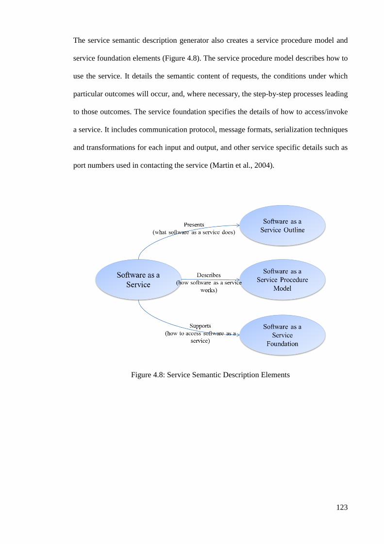
123
The service semantic description generator also creates a service procedure model and
service foundation elements (Figure 4.8). The service procedure model describes how to
use the service. It details the semantic content of requests, the conditions under which
particular outcomes will occur, and, where necessary, the step-by-step processes leading
to those outcomes. The service foundation specifies the details of how to access/invoke
a service. It includes communication protocol, message formats, serialization techniques
and transformations for each input and output, and other service specific details such as
port numbers used in contacting the service (Martin et al., 2004).
Figure 4.8: Service Semantic Description Elements

124
4.4.2.2.2 Service Semantic Description Editor
Using the service semantic description editor, semantic interoperability layer can add
details such as non-functional parameters (e.g., quality rating) in the service outline
element, control flow and data flow information in the service procedure model
element, and special data transformations in the service foundation element (Figure 4.9).
Figure 4.9: Service Semantic Description Editor
4.4.2.2.3 Service Semantic Description Verification
At this stage, the created service semantic description should be studied and validated.
Therefore, services description is changed from syntactic state to semantic state by
performing the above actions by cloud broker allowing dynamic discovery and
invocation of services or semantic interoperability.
4.4.2.3 Service Semantic Description Deployment
The actual service has to be deployed on a server where it is accessible to the cloud
software as a service consumer systems. Its service outline has to be deployed on a
public server where it is accessible by the Intermediary (Figure 4.1).

125
4.4.2.4 Service Description Registration
One of the other duties of cloud broker is to register description of services. Service
description registration section first registers semantic description of services in
intermediary and then converts semantic description of services to syntactic description
by semantic to syntactic convertor and registers syntactic description of services in
intermediary. This conversion is required for service discovery (Figure 4.10).
Figure 4.10: Service Description Registration
4.4.2.5 Ontologies Repository
In cloud computing environments, software as a service systems are frequently added or
deleted. In such environments, what will happen if the software as a service used by a
customer is deleted, changed, or more efficient service is provided? Dynamic discovery
and invocation of services can be applied for solving such problems. One of the
approaches used for this purpose is ontology.
Ontologies describe the hierarchical organization of ideas in a domain in a way that can
be parsed and understood by a software program. Ontologies are similar to an object-
oriented class hierarchy in a software program. The data model which is made for
representing knowledge of a special domain, arguing about the objects available in that
domain and describing the relationship between the domain entities is called ontology.

126
An ontology is an abstract attitude of a domain which is modelled and its aim is to
obtain knowledge of a domain. In ontology, an explicit and implicit description of the
concepts as classes, relations, functions, principles and samples is given. Ontology
provides concepts for representing meaning. Semantic network available in ontology
provides search space for searching the concepts.
Ontology is created for describing features and serviceability translatable for computer
and allows the providers of service to define their service based on ontology. In other
words, inputs and outputs of service and preconditions and postconditions of its
invocation based on ontology are presented. Ontology classifies concepts of a domain as
perceivable hierarchies for computers.
To create an ontology, developers must work with domain experts to create an ontology
of the knowledge domain in which the services will reside. Then a procedure model can
be created that describes how consumers will interact with the service. Only then can
the programmatic interfaces for the service be defined, as indicated in Figure 4.11.

127
Figure 4.11: Ontology Creation
4.4.2.6 Unified Service Request Generator
Using the unified service request generator, a service request was created, including the
ontological descriptions of the inputs and outputs desired from a potential service. Like
the service outline, this service request can be published to a web server where it will be
accessible to the intermediary.
4.4.2.7 Intermediary
One of the other components of cloud broker is intermediary of which duty is to
discover services. The intermediary is responsible for responding to consumers of cloud
software as a service system. Cloud software as a service consumer can query it to
discover for the desired service.

128
The intermediary serves as a “catalog” of services. Service description registration
registers descriptions of services with the intermediary. Service consumers can query
the intermediary with an ontological description of the desired inputs and outputs. The
intermediary matches the request with its catalog of services and returns a ranked list of
services that most closely match the request. The intermediary elements have an
application programming interface to discover services.
4.4.2.8 Mediator
The mediator is applied for invoking services. Consumers of cloud software as a service
systems first select a service from list of the services provided by intermediary. Then,
consumers of cloud software as a service systems set their requests based on input
conditions described by ontology and send them to mediator. Mediator formats the
requests based on the format defined by service and sends it to service. Response is
received from the service and sent to the cloud software as a service consumer.
The service consumers do not need to know anything about how to interact with the
actual web service. The mediator has an application programming interface to invoke
services.

129
4.4.3 Cloud Software as a Service Consumer Component
Cloud software as a service consumer can be a cloud software as a service system or a
consumer application which is used by an end user (Figure 4.12). The main activity of
cloud consumer is to discover and invoke services.
Figure 4.12: Use Case for Cloud Software as a Service Consumer

130
4.4.3.1 Cloud Software as a Service Discovery
In order for cloud software as a service discovery to use the desired services, the
consumer should discover it in the first instance. Stages of discovering cloud software
as a service systems are shown in Figure 4.13.
Figure 4.13: Cloud Software as a Service Discovery
As shown in Figure 4.13, cloud software as a service consumer should create its request
for discovering service through unified service request generator of cloud broker. In the
next stage, cloud software as a service consumer should send its request to intermediary.
In other words, cloud software as a service consumer should query intermediary for
finding the desired service. At the end, cloud software as a service consumer should
select the most suitable service among services sent by intermediary.

131
4.4.3.2 Cloud Software as a Service Invocation
Cloud software as a service consumer should invoke service after discovering service.
In order to invoke service, cloud software as a service consumer should send service
invocation to mediator which is in cloud broker section and receive the invoked service
from mediator. These activities are shown in Figure 4.14.
Figure 4.14: Cloud Software as a Service Invocation

132
4.5 Architecture of the Semantic Interoperability Framework for Software as a
Service Systems in Cloud Computing Environments
Figure 4.15 summarizes architecture of the semantic interoperability framework for
software as a service systems in cloud computing environments. Architecture of cloud
software as a service semantic interoperability framework includes actors, components
of each one of the actors and interoperability between actors and components.
Figure 4.15: Architecture of Cloud Software as a Service Semantic Interoperability
Framework

133
4.6 Summary
In this chapter, the proposed semantic interoperability framework for software as a
service systems in cloud computing environments was designed and explained in detail.
In the first step, actors and relationships between actors in the cloud semantic
interoperability framework for software as a service systems was introduced. The cloud
semantic interoperability framework for software as a service systems defines three
major actors: cloud software as a service provider, cloud broker, and cloud software as a
service consumer. Then components in the proposed semantic interoperability
framework for software as a service systems in cloud computing environments was
described. The development of the components was classified according to the actors in
the cloud software as a service semantic interoperability framework. After that,
architecture of the cloud semantic interoperability framework for software as a service
systems was explained. Architecture of cloud software as a service semantic
interoperability framework includes actors, components of each one of the actors and
interoperability between actors and components. It includes the sequence of events that
would occur at runtime in a dynamic discovery and invocation environment of cloud
software as a service systems registered with the intermediary.

134
5.0 IMPLEMENTATION OF SEMANTIC INTEROPERABILITY
FRAMEWORK FOR SOFTWARE AS A SERVICE SYSTEMS IN
CLOUD COMPUTING ENVIRONMENTS
5.1 Introduction
In the previous chapter, the design of the semantic interoperability framework for
software as a service systems in cloud computing has been defined. Earlier in
section 2.3.3, the available technologies to achieving to interoperability were
introduced. This chapter elaborates the details of implementation of the cloud semantic
interoperability framework for software as a service systems. The semantic
interoperability framework for software as a service systems in cloud computing
environments was implemented based on suitable technologies and instruments
available for interoperability.

135
5.2 Setting Up the Semantic Interoperability Development Environment for
Cloud Software as a Service Systems
The first step in implementing the semantic interoperability framework for software as a
service systems in cloud computing environments was to select the development
environment. It was essential to select tools for which direct and personal support was
available during the development of the cloud semantic interoperability framework for
software as a service systems. Fortunately, the Intelligent Software Agents Lab at
Carnegie Mellon University has played a critical role in the development of semantic
interoperability from its very inception (ISAL, 2001). This group developed CMU’s
OWL-S Development Environment (CODE) (ISAL, 2004; Srinivasan, Paolucci, &
Sycara, 2005). CODE supports the complete web services development process—from
the generation of services descriptions to the deployment and registration of the service.
CODE is implemented as an Eclipse plug-in that supports activities for software as a
service providers and software as a service consumer system developers. In addition to
tools for the description of services, CODE includes the Matchmaker and the Virtual
Machine (VM) elements. Thus, CODE was selected as the development environment,
and support was graciously provided by Naveen Srinivasan of the Intelligent Software
Agents Lab.
5.3 Creating Cloud Software as a Service Systems
The next step was to create cloud software as a service systems that could be accessed
using cloud broker in the proposed cloud software as a service semantic interoperability
framework. The software as a service system should provide similar capabilities
through different interfaces. Operations with different interfaces but similar ontological
meanings would provide for more meaningful queries and results. The software as a

136
service system should provide a number of simple operations that can be used to test the
basic capabilities of the proposed cloud software as a service semantic interoperability
framework. These simple operations would be composable into more complex
processes. A service syntactic description must be available for the software as a service
system and there must be no cost to access the software as a service system.
Based on these criteria, Microsoft Research Maps service (MicrosoftCorporation, 2013)
was adopted as the software as a service system and deployed on salesforce.com
(Pullarao & Thirupathirao, 2013). Microsoft Research Maps service is freely available
and provides a number of operations that perform simple tasks, such as converting
between location coordinate units, and more complex operations to retrieve maps and
photos of specified areas (Barclay, Gray, Strand, Ekblad, & Richter, 2002). The created
cloud software as a service systems can be found in Appendix A.
5.4 Creating Service Interface for Cloud Software as a Service Systems
In this stage, service interface was created for each one of the cloud software as a
service systems and each one of the service interfaces created for the cloud software as
a service systems was described. For each one of the service interfaces, a description
file was separately created. A describable file of each service is a WSDL file.
After describing service interface for cloud software as a service systems, service level
agreement (SLA) which includes different aspects such as reliability, security and
efficiency was managed and finally registered in cloud broker in unified interoperability
interface (For the service interface generated for cloud software as a service systems,
see Appendix B).

137
5.5 Creating the Ontology
The next step in implementing the cloud software as a service semantic interoperability
framework for software as a service systems in cloud computing environments was to
create an ontology to represent the mapping knowledge space. The ontology has to
describe not only the different types of maps that a consumer might wish to access but
also the different concepts that describe the maps themselves. Fortunately many
complete and easy-to-use tools exist for creating ontologies. The Protégé Ontology
Editor was selected to develop the ontology (Stanford, 2006). Protégé is an open source
ontology editor that allows knowledge providers to create knowledge bases easily via a
graphical editor. Using Protégé, an ontology was created that defines some of the core
concepts related to mapping services. The complete ontology can be found in Appendix
C.
5.6 Unified Interoperability Interface
As mentioned in Section 5.4, cloud software as a service provider creates their
description file after creating service interface for each one of cloud software as a
service systems which wants to participate in interoperability and gives it to unified
interoperability interface from cloud broker. Therefore, the unified interoperability
interface is responsible for establishing the relationship between cloud software as a
service provider and cloud broker. Unified interoperability interface after receiving
description of each service, gives the service to semantic interoperability layer which is
another component of cloud broker.

138
5.7 Generating the Semantic Description of the Software as a Service Systems
The first step in the dynamic management of services is to create a semantic description
of services. In this stage, syntactic services description should be changed such that they
make semantic interoperability possible. For this purpose, this activity starts by
receiving syntactic service description from unified interoperability interface via
semantic interoperability layer. Semantic interoperability layer gives syntactic service
description file to service semantic description generator to generate semantic
description file of service. Using the WSDL2OWL-S component (Figure 5.1) included
in CODE, the service outline (Profile) was generated for the web service interfaces (For
the Service Outline (Profile) element generated, see Appendix D).
Figure 5.1: Service Semantic Description Files Generated from a Service Syntactic
Description Definition

139
Using the OWL-S Editor, the service semantic description editor can add details such as
special data transformations in the Service Foundation (Grounding) element
(Figure 5.2), control flow and data flow information in the Service Procedure (Process)
Model element (Figure 5.3), and non-functional parameters (e.g., quality rating) in the
Service Outline (Profile) element (For the Service Procedure (Process) Model element
generated, see Appendix E; and for the Service Foundation (Grounding) element
generated, see Appendix F).
Figure 5.2: Service Grounding Editor

140
Figure 5.3: Service Process Editor
Using the OWL-S Editor to modify the service outline (profile), we mapped the input
and output parameters of the operations to their counterparts in the ontology created
earlier (Figure 5.4). We then used the Service Semantic Description Verification to
validate the service outline file.

141
Figure 5.4: Service Profile Editor
5.8 Deploying the Service Semantic Description
In order to advertise it through the intermediary, the service semantic description must
be accessible. As a result, we deployed and published it on a web server for the
intermediary to access.
5.9 Register the Service Description with the Intermediary
Using the OWL-S2UDDI component included with CODE, the service semantic
description was converted to service syntactic description and registered to intermediary
(OWL-S Matchmaker). The intermediary then registered the service syntactic and
semantic description in its database and made it available for discovery. Registration of
service description on the intermediary is presented in Figure 5.5.

142
Figure 5.5: Service Description Registration on the Intermediary
5.10 Service Discovery
Using the unified service request generator (OWL-S Editor component included with
CODE), a service request was created, including the ontological descriptions of the
inputs and outputs desired from a potential service. This service request must be
accessible to the intermediary.
Using the software as a service consumer application, the intermediary was queried for
services that most closely matched the service request. The intermediary successfully
returned a set of services ranked by how well they matched the request.
Now that we verified that the ontology had been correctly defined and that the
intermediary worked with the created requests and profiles, the next step was to initiate
requests from a consumer application.
5.11 Service Invocation
In order to invoke service selected by cloud software as a service consumer application,
OWL-S VM as mediator, which is another component of CODE, was used. OWL-S
VM converted request syntactically which is understandable for service interface and

143
sent it to the cloud in which service interface was located and returned response
received from service interface to the service consumer.
5.12 Overview of Implementation
This section describes the implementation overview of the proposed semantic
interoperability framework for software as a service systems in cloud computing
environments. The first step in implementing the proposed semantic interoperability
framework for software as a service systems in cloud computing environments was to
select the development environment. The next step was to create cloud software as a
service systems that could potentially be accessed using cloud software as a service
semantic interoperability framework. In this stage, web service interface was created for
each cloud software as a service systems and each web service interfaces created for the
cloud software as a service systems was described. For each web service interface, a
description file was separately created.
The next step in implementing the cloud semantic interoperability framework for
software as a service systems was to create an ontology domain to represent the
knowledge space. The unified interoperability interface is responsible for establishing
the relationship between cloud software as a service provider and cloud broker. Unified
interoperability interface gives the description of each service to semantic
interoperability layer. In the next step, syntactic services description should be changed
such that they make semantic interoperability possible. For this purpose, this activity
starts by receiving syntactic service description from unified interoperability interface
by semantic interoperability layer. Semantic interoperability layer gives syntactic
services description file to service semantic description generator to generate semantic
description file of the service. After that, the cloud broker was deployed and published

144
the semantic description of service on a web server for the intermediary to access. In
this stage, using the OWL-S2UDDI component included with CODE, the service
semantic description was converted to service syntactic description and registered to
intermediary for service discovery. Using the software as a service consumer
application, the intermediary was queried and the service was returned successfully.
Finally, in order for service invocation by cloud software as a service consumer
application, mediator was used. The mediator converted request syntactically which is
understandable for service and sent it to the cloud where service interface is located, and
gave response from the cloud to software as a service consumer application.
5.13 Summary
In this chapter, the proposed semantic interoperability framework for software as a
service systems in cloud computing environments was implemented based on suitable
technologies and instruments for interoperability. The main steps of implementation
were creating cloud software as a service system, web service interface, and an ontology
domain, and generating semantic description, service discovery, and service invocation.
Based on the implementation, the next chapter focuses on evaluation strategies and
analysis of the results to demonstrate the effectiveness of the proposed semantic
interoperability framework for software as a service systems in cloud computing
environments.

145
6.0 RESULTS EVALUATION AND DISCUSSION
6.1 Introduction
This chapter describes evaluation strategies applied andevaluationresults’analysisof
the semantic interoperability framework for software as a service systems in cloud
computing environments. The evaluation results were analysed to identify whether the
cloud semantic interoperability framework for software as a service systems meets the
requirements which has been established in Chapter 3. In other words, the functional
and non functional requirements of the semantic interoperability were evaluated to show
the effectiveness of the semantic interoperability framework for software as a service
systems in cloud computing environments.
The plan of empirically evaluating the proposed semantic interoperability framework
for software as a service systems in cloud computing environments was organized with
respect to the plan recommended by Wohlin et al. (2012), which is a complete resource
to deal with experimental evaluation in software engineering. First of all, experimental
design that were performed to analyse the effectiveness of the proposed semantic
interoperability framework for software as a service in cloud computing environments is
described in Section 6.2. The hypotheses of this experiment are defined in Section 6.3
and the evaluation criteria to assess these hypotheses are discussed in Section 6.4. In
Section 6.5, statistical analysis is described. The evaluation results and discussion are
given in Section 6.6 and Section 6.7.
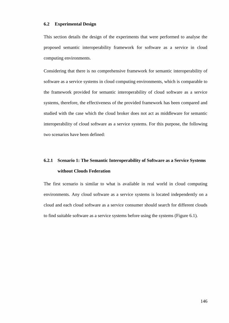
146
6.2 Experimental Design
This section details the design of the experiments that were performed to analyse the
proposed semantic interoperability framework for software as a service in cloud
computing environments.
Considering that there is no comprehensive framework for semantic interoperability of
software as a service systems in cloud computing environments, which is comparable to
the framework provided for semantic interoperability of cloud software as a service
systems, therefore, the effectiveness of the provided framework has been compared and
studied with the case which the cloud broker does not act as middleware for semantic
interoperability of cloud software as a service systems. For this purpose, the following
two scenarios have been defined:
6.2.1 Scenario 1: The Semantic Interoperability of Software as a Service Systems
without Clouds Federation
The first scenario is similar to what is available in real world in cloud computing
environments. Any cloud software as a service systems is located independently on a
cloud and each cloud software as a service consumer should search for different clouds
to find suitable software as a service systems before using the systems (Figure 6.1).
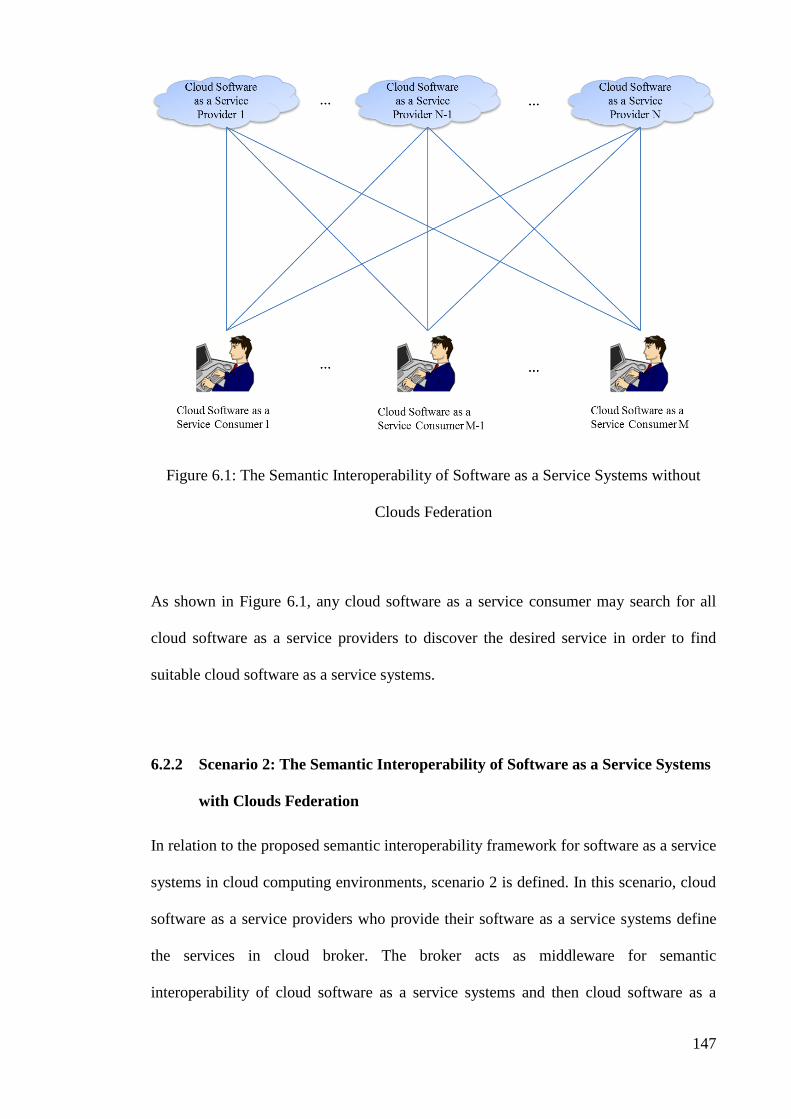
147
Figure 6.1: The Semantic Interoperability of Software as a Service Systems without
Clouds Federation
As shown in Figure 6.1, any cloud software as a service consumer may search for all
cloud software as a service providers to discover the desired service in order to find
suitable cloud software as a service systems.
6.2.2 Scenario 2: The Semantic Interoperability of Software as a Service Systems
with Clouds Federation
In relation to the proposed semantic interoperability framework for software as a service
systems in cloud computing environments, scenario 2 is defined. In this scenario, cloud
software as a service providers who provide their software as a service systems define
the services in cloud broker. The broker acts as middleware for semantic
interoperability of cloud software as a service systems and then cloud software as a

148
service consumers communicate only with the broker in order to use services on
different clouds. The consumers do not need to search for and communicate directly
with the clouds on which the services are located (Figure 6.2).
Figure 6.2: The Semantic Interoperability of Software as a Service Systems with Clouds
Federation
As shown in Figure 6.2, any cloud software as a service consumers only search with a
single cloud broker in order to find suitable cloud software as a service systems in this
scenario.
149
6.3 Hypotheses
With respect to the contributions of this research which is a comprehensive semantic
interoperability framework for software as a service systems in cloud computing
environments, we defined several hypotheses. The testing of the hypotheses, in this
research, is based on the performance and effectiveness metrics. The null hypotheses are
formulated as follows:
• : There is no significant difference between the
interoperability time of the scenario with clouds federation (based on the
proposed semantic interoperability framework for software as a service systems
in cloud computing environments), and the scenario without clouds federation.
• : There is no significant difference between the
interoperability quality of the scenario with clouds federation (based on the
proposed semantic interoperability framework for software as a service systems
in cloud computing environments), and the scenario without clouds federation.
• : There is no significant difference between the
interoperability cost of the scenario with clouds federation (based on the
proposed semantic interoperability framework for software as a service systems
in cloud computing environments), and the scenario without clouds federation.
• : There is no significant difference between the conformity of the
scenario with clouds federation (based on the proposed semantic interoperability
framework for software as a service systems in cloud computing environments),
and the scenario without clouds federation.

150
The alternative hypotheses for performance and effectiveness can be derived
analogously from the above list of hypotheses. If a null hypothesis can be rejected with
high confidence, the corresponding alternative hypothesis can be supported. The
alternative hypotheses corresponding to the defined null hypotheses are listed in below.
• : The interoperability time of the scenario with clouds
federation (based on the proposed semantic interoperability framework for
software as a service systems in cloud computing environments) has significant
difference from the interoperability time of the scenario without clouds
federation.
• : The interoperability quality of the scenario with clouds
federation (based on the proposed semantic interoperability framework for
software as a service systems in cloud computing environments) has significant
difference from the interoperability quality of the scenario without clouds
federation.
• : The interoperability cost of the scenario with clouds
federation (based on the proposed semantic interoperability framework for
software as a service systems in cloud computing environments) has significant
difference from the interoperability cost of the scenario without clouds
federation.
• : The conformity of the scenario with clouds federation (based on
the proposed semantic interoperability framework for software as a service
systems in cloud computing environments) has significant difference from the
conformity of the scenario without clouds federation.

151
6.4 Evaluation Criteria
To evaluate the effectiveness of the proposed semantic interoperability framework for
software as a service systems in cloud computing environments, performance measures
were used. The performance measures are concerned with the exchange of information
and use of information exchanged (Daclin et al., 2006).
6.4.1 Interoperability Time
Interoperability time is defined as the time when there is interoperability between cloud
software as a service providers and cloud software as a service consumer and
interoperability is completed (Daclin et al., 2006). In other words, interoperability time
is defined as the real duration of the interoperability.
6.4.2 Interoperability Quality
Ratio of successful interoperability to total number of interoperability is called
interoperability quality (Daclin et al., 2006). In other words, the percent of
interoperability that succeeded is considered as interoperability quality.
6.4.3 Interoperability Cost
The cost spent for performing interoperability action between cloud software as a
service provider and cloud software as a service consumer is called interoperability cost
(Daclin et al., 2006). In other words, the real cost of interoperability is the number of
service requests and responses that performed.

152
6.4.4 Conformity
Conformity relates to the extent to which the exchanged information in interoperability
process is used. Ratio of the information conforming to the requested information to the
information received in interoperability process is called conformity (Daclin et al.,
2006). In other words, the percent of information conforming is considered as
conformity.
The goal of each criteria for evaluating the effectiveness of the proposed semantic
interoperability framework for software as a service systems in cloud computing
environments is shown in Table 6.1.
Table 6.1: Evaluation Criteria Goal
EvaluationCriteria Goal
InteroperabilityTime Minimum
InteroperabilityQuality Maximum
InteroperabilityCost Minimum
Conformity Maximum
153
6.5 Statistical Analysis
In order to further analyse the results, statistical analysis must be accomplished to
determine if the difference between the effectiveness and performance of two
frameworks or models is significant or not. For statistical analysis, we used the non
parametric Wilcoxons matched-pairs signed-ranked test that works on the paired data.
The Wilcoxon test is a nonparametric test that compares two paired groups. The test
essentially calculates the difference between each set of pairs and analyses these
differences. The Wilcoxon Signed Rank test assumes that there is information in the
magnitudes and signs of the differences between paired observations. As the
nonparametric equivalent of the paired student's t-test, the Signed Rank can be used as
an alternative to the t-test when the population data does not follow a normal
distribution (Takagi, 2013). In this statistical analysis, the test determines whether the
improvement obtained from our approach in terms of using noun-only and using the
proposed term-weighting technique is statistically significant or not. In this evaluation,
the significance level of the Wilcoxon is α <= 0.05.
In this research, IBM SPSS Statistics 19 was used in the implementation of statistical
analysis (Wilcoxon matched-pairs signed-ranked test). IBM SPSS Statistics is used
primarily for statistical analysis and provides tools to analyse data and to create reports
and graphs from that data.
6.6 Results Evaluation
This section shows the results of the evaluation. In the evaluation process, evaluation
criteria defined in Section 6.4, have been performed separately on each one of the two
scenarios defined in Section 6.2. The results of the evaluation and statistical analysis are
given based on the evaluation criteria.

154
For each of the evaluation criteria, instances of software as a services had been applied
on different service providers. Three measurements were taken and the arithmetic mean
is calculated, and rounded to the nearest 0.1 as the result.
6.6.1 Interoperability Time
As mentioned in Section 6.4.1, the interoperability time is defined as the time when
there is interoperability between cloud software as a service providers and cloud
software as a service consumer and interoperability is completed. In other words,
interoperability time is defined as the real duration of the interoperability. With increase
in the number of cloud software as a service providers, interoperability time has been
calculated for the first scenario and the second scenario in terms of seconds. The results
of interoperability time (real duration of interoperability) evaluation are shown in
Appendix G.
The results of statistical Wilcoxon matched-pairs signed-ranked test for comparing
differences in interoperability time between the two scenarios are shown in Table 6.2,
Table 6.3, and Table 6.4.
Table 6.2: Descriptive Statistics for Interoperability Time
N Mean Std. Deviation Minimum Maximum
Interoperability Time (Real
Duration of Interoperability)
Without Clouds Federation
10 11.000 6.0553 2.0 20.0
Interoperability Time (Real
Duration of Interoperability)
With Clouds Federation
10 2.350 .3028 1.9 2.8

155
Table 6.3: Wilcoxon Signed Ranks Test for Interoperability Time
N Mean Rank Sum of Ranks
Interoperability Time (Real Duration
of Interoperability) With Clouds
Federation - Interoperability Time
(Real Duration of Interoperability)
Without Clouds Federation
Negative Ranks 10a 5.50 55.00
Positive Ranks 0b .00 .00
Ties 0c
Total 10
a. Interoperability Time (Real Duration of Interoperability) With Clouds Federation < Interoperability Time
(Real Duration of Interoperability) Without Clouds Federation
b. Interoperability Time (Real Duration of Interoperability) With Clouds Federation > Interoperability Time
(Real Duration of Interoperability) Without Clouds Federation
c. Interoperability Time (Real Duration of Interoperability) With Clouds Federation = Interoperability Time
(Real Duration of Interoperability) Without Clouds Federation
Table 6.4: Wilcoxon Signed Ranks Test Statistics for Interoperability Time
Interoperability Time (Real Duration of Interoperability) With Clouds Federation
- Interoperability Time (Real Duration of Interoperability) Without Clouds
Federation
Z -2.803a
Asymp. Sig. (2-tailed) .005
a. Based on positive ranks.
In Table 6.4, statistically significant result of the Wilcoxon tests that indicates the
rejection of the corresponding null hypothesis is presented in bold (α = .005). The
statistical test on the interoperability time shows the rejection of the corresponding null
hypothesis and consequently acceptance of the alternative hypothesis. Results of
interoperability time evaluation have been compared with increase in the number of
cloud software as a service providers for the first scenario and the second scenario
(Figure 6.3).

156
Figure 6.3: Interoperability Time Results Evaluation
As shown in Figure 6.3, with increase in the number of cloud software as a service
providers in the first scenario, interoperability time considerably increases but
interoperability time in the second scenario does not considerably change with increase
of the number of service providers. It can be concluded that interoperability time in the
second scenario is shorter than that in the first scenario based on the time needed for
interoperability. Considering that the goal is to reduce interoperability time during
interoperability, therefore, the second scenario performs better than the first scenario.
In addition, interoperability time was calculated based on the time needed for
discovering service in relation to the number of cloud software as a service providers in
both scenarios. The results of interoperability time (real duration of service discovery)
evaluation are shown in Appendix G.
0
2
4
6
8
10
12
14
16
18
20
1 2 3 4 5 6 7 8 9 10
Inte
rop
era
bili
ty T
ime
(R
eal D
ura
tio
n o
f In
tero
per
abili
ty)
(Sec
)
Cloud Software as a Service Provider Number
Without CloudsFederation
With CloudsFederation(Proposed SemanticInteroperabilityFramework)
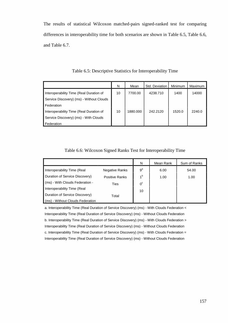
157
The results of statistical Wilcoxon matched-pairs signed-ranked test for comparing
differences in interoperability time for both scenarios are shown in Table 6.5, Table 6.6,
and Table 6.7.
Table 6.5: Descriptive Statistics for Interoperability Time
N Mean Std. Deviation Minimum Maximum
Interoperability Time (Real Duration of
Service Discovery) (ms) - Without Clouds
Federation
10 7700.00 4238.710 1400 14000
Interoperability Time (Real Duration of
Service Discovery) (ms) - With Clouds
Federation
10 1880.000 242.2120 1520.0 2240.0
Table 6.6: Wilcoxon Signed Ranks Test for Interoperability Time
N Mean Rank Sum of Ranks
Interoperability Time (Real
Duration of Service Discovery)
(ms) - With Clouds Federation -
Interoperability Time (Real
Duration of Service Discovery)
(ms) - Without Clouds Federation
Negative Ranks 9a 6.00 54.00
Positive Ranks 1b 1.00 1.00
Ties 0c
Total
10
a. Interoperability Time (Real Duration of Service Discovery) (ms) - With Clouds Federation <
Interoperability Time (Real Duration of Service Discovery) (ms) - Without Clouds Federation
b. Interoperability Time (Real Duration of Service Discovery) (ms) - With Clouds Federation >
Interoperability Time (Real Duration of Service Discovery) (ms) - Without Clouds Federation
c. Interoperability Time (Real Duration of Service Discovery) (ms) - With Clouds Federation =
Interoperability Time (Real Duration of Service Discovery) (ms) - Without Clouds Federation

158
Table 6.7: Wilcoxon Signed Ranks Test Statistics for Interoperability Time
Interoperability Time (Real Duration of Service Discovery) (ms) - With Clouds
Federation –
Interoperability Time (Real Duration of Service Discovery) (ms) - Without
Clouds Federation
Z -2.701a
Asymp. Sig. (2-tailed) .007
a. Based on positive ranks.
In Table 6.7, statistically significant result of the Wilcoxon tests that indicates the
rejection of the corresponding null hypothesis is presented in bold (α = .007). The
statistical test on the interoperability time results shows the rejection of the
corresponding null hypothesis and consequently acceptance of the alternative
hypothesis.
Interoperability time evaluation results have been compared based on time needed for
discovering service with increase in the number of cloud software as a service providers
for both scenarios and are shown in Figure 6.4.
Figure 6.4: Interoperability Time Results Evaluation
0
1000
2000
3000
4000
5000
6000
7000
8000
9000
10000
11000
12000
13000
14000
15000
1 2 3 4 5 6 7 8 9 10
Inte
rop
era
bil
ity
Tim
e
(Re
al D
ura
tio
n o
f Se
rvic
e D
isco
very
) (m
s)
Cloud Software as a Service Provider Number
Without CloudsFederation
With CloudsFederation(Proposed SemanticInteroperabilityFramework)

159
As shown in Figure 6.4, interoperability time considerably increases for time needed to
discover services with increase in the number of cloud software as a service providers in
the first scenario but does not considerably change in the second scenario. It can be
concluded that that interoperability time in the second scenario is shorter than that in the
first scenario. Considering that the goal is to reduce interoperability time based on the
time needed for discovering service, therefore, the second scenario performs better than
the first scenario.
6.6.2 Interoperability Quality
As mentioned in Section 6.4.2, the ratio of successful interoperability to total number of
interoperability is called interoperability quality. In other words, the percent of
interoperability that succeeded is considerd as interoperability quality. With increase in
the number of cloud software as a service requests, interoperability quality has been
extracted separately for the first scenario and the second scenario in terms of percent.
The results of interoperability quality evaluation are shown in Appendix G.
The results of statistical Wilcoxon matched-pairs signed-ranked test for comparing
differences in interoperability quality between the two scenarios are shown in Table 6.8,
Table 6.9, and Table 6.10.
Table 6.8: Descriptive Statistics for Interoperability Quality
N Mean Std. Deviation Minimum Maximum
Interoperability Quality
(Success Rate) % - without
Clouds Federation
10 30.410 23.8332 9.1 80.1
Interoperability Quality
(Success Rate) % - with
Clouds Federation
10 80.570 6.4310 76.3 95.3

160
Table 6.9: Wilcoxon Signed Ranks Test for Interoperability Quality
N Mean Rank Sum of Ranks
Interoperability Quality (Success Rate)
% - with Clouds Federation -
Interoperability Quality (Success Rate)
% - without Clouds Federation
Negative Ranks 0a .00 .00
Positive Ranks 10b 5.50 55.00
Ties 0c
Total 10
a. Interoperability Quality (Success Rate) % - with Clouds Federation < Interoperability Quality (Success
Rate) % - without Clouds Federation
b. Interoperability Quality (Success Rate) % - with Clouds Federation > Interoperability Quality (Success
Rate) % - without Clouds Federation
c. Interoperability Quality (Success Rate) % - with Clouds Federation = Interoperability Quality (Success
Rate) % - without Clouds Federation
Table 6.10: Wilcoxon Signed Ranks Test Statistics for Interoperability Quality
Interoperability Quality (Success Rate) % - with Clouds Federation -
Interoperability Quality (Success Rate) % - without Clouds Federation
Z -2.803a
Asymp. Sig. (2-tailed) .005
a. Based on negative ranks.
In Table 6.10, statistically significant result of the Wilcoxon tests that indicates the
rejection of the corresponding null hypothesis is presented in bold (α = .005). The
statistical test on the interoperability quality results shows the rejection of the
corresponding null hypothesis and consequently acceptance of the alternative
hypothesis.
Interoperability quality evaluation results have been compared between both scenarios
with increase in the number of cloud software as a service requests and are shown in
Figure 6.5.

161
Figure 6.5: Interoperability Quality Results Evaluation
As shown in Figure 6.5, with increase in the number of cloud software as a service
requests in the first scenario, interoperability quality considerably decreases but
interoperability quality in the second scenario decreases negligibly, and falls within a
specified range (between 76% and 96%). It can be concluded that interoperability
quality in the second scenario is higher than that in the first scenario based on success
rate for interoperability. Considering that the goal is to increase interoperability quality,
therefore, the second scenario performs better than the first scenario.
6.6.3 Interoperability Cost
As mentioned in Section 6.4.3, the cost spent for performing interoperability action
between cloud software as a service provider and cloud software as a service consumer
is called interoperability cost. In other words, the real cost of interoperability is the
0
10
20
30
40
50
60
70
80
90
100
50 100 150 200 250 300 350 400 450 500
Inte
rop
era
bili
ty Q
ual
ity
(Su
cces
s R
ate)
%
Cloud Software as a Service Request Number
Without CloudsFederation
With CloudsFederation(Proposed SemanticInteroperabilityFramework)

162
number of service requests and responses that performed. Interoperability cost has been
calculated for the first scenario and the second scenario with increase in the number of
cloud software as a service providers. The results of interoperability cost (number of
service request and response) evaluation are shown in Appendix G.
The results of statistical Wilcoxon matched-pairs signed-ranked test for comparing
differences in interoperability cost between both scenarios are shown in Table 6.11,
Table 6.12, and Table 6.13.
Table 6.11: Descriptive Statistics for Interoperability Cost
N Mean Std. Deviation Minimum Maximum
Interoperability Cost
(Number of Service
Request and Response) -
Without Clouds Federation
100 99.010 58.0058 1.0 198.0
Interoperability Cost
(Number of Service
Request and Response) -
With Clouds Federation
100 1.4950 .29011 1.00 1.99
Table 6.12: Wilcoxon Signed Ranks Test for Interoperability Cost
N Mean Rank Sum of Ranks
Interoperability Cost
(Number of Service Request
and Response) - With
Clouds Federation -
Interoperability Cost
(Number of Service Request
and Response) - Without
Clouds Federation
Negative Ranks 99a 50.00 4950.00
Positive Ranks 0b .00 .00
Ties 1c
Total
100
a. Interoperability Cost (Number of Service Request and Response) - With Clouds Federation <
Interoperability Cost - Without Clouds Federation
b. Interoperability Cost (Number of Service Request and Response) - With Clouds Federation >
Interoperability Cost - Without Clouds Federation
c. Interoperability Cost (Number of Service Request and Response) - With Clouds Federation =
Interoperability Cost - Without Clouds Federation

163
Table 6.13: Wilcoxon Signed Ranks Test Statistics for Interoperability Cost
Interoperability Cost (Number of Service Request and Response) - With
Clouds Federation - Interoperability Cost (Number of Service Request and
Response) - Without Clouds Federation
Z -8.638a
Asymp. Sig. (2-tailed) .001
a. Based on positive ranks.
In Table 6.13 statistically significant result of the Wilcoxon tests that indicates the
rejection of the corresponding null hypothesis is presented in bold (α = .001). The
statistical test on the interoperability cost results shows the rejection of the
corresponding null hypothesis and consequently acceptance of the alternative
hypothesis.
Interoperability cost evaluation results are compared and shown in Figure 6.6 with
increase in the number of cloud software as a service providers for the first and second
scenarios.

164
Figure 6.6: Interoperability Cost Results Evaluation
As shown in Figure 6.6, interoperability cost in the first scenario increases when the
number of cloud software as a service providers increases. In the second scenario,
interoperability cost falls within a specified range with increase in the number of cloud
software as a service providers. It can be concluded that interoperability cost in the first
scenario considerably increases while interoperability cost does not increase
considerably in the second scenario. Considering that the goal is to reduce
interoperability cost based on the number of service request and response, therefore, the
second scenario performs better than the first scenario.
1
2
4
8
16
32
64
128
256
1 7
13
19
25
31
37
43
49
55
61
67
73
79
85
91
97
Inte
rop
erab
ility
Co
st
(Nu
mb
er
of
Serv
ice
Req
ues
t an
d R
esp
on
se)
Cloud Software as a Service Provider Number
Without CloudsFederation
With Clouds Federation(Proposed SemanticInteroperabilityFramework)

165
6.6.4 Conformity
As mentioned in Section 6.4.4, conformity relates to the extent to which the exchanged
information in interoperability process is used. Ratio of the information conforming to
the requested information to the information received in interoperability process is
called conformity. In other words, the percent of information conforming is considerd
as conformity. Conformity has been calculated for the first scenario and the second
scenario with increase in the number of cloud software as a service in terms of percent.
The results of Conformity evaluation are shown in Appendix G.
The results of statistical Wilcoxon matched-pairs signed-ranked test for comparing
differences between both scenarios are shown in Table 6.14, Table 6.15, and Table 6.16.
Table 6.14: Descriptive Statistics for Conformity
N Mean Std. Deviation Minimum Maximum
Conformity % - Without
Clouds Federation
10 16.600 10.3586 5.0 29.0
Conformity % - With Clouds
Federation
10 53.800 7.1554 42.0 59.0
Table 6.15: Wilcoxon Signed Ranks Test for Conformity
N Mean Rank Sum of Ranks
Conformity % - With Clouds
Federation - Conformity % -
Without Clouds Federation
Negative Ranks 0a .00 .00
Positive Ranks 5b 3.00 15.00
Ties 0c
Total 5
a. Conformity % - With Clouds Federation < Conformity % - Without Clouds Federation
b. Conformity % - With Clouds Federation > Conformity % - Without Clouds Federation
c. Conformity % - With Clouds Federation = Conformity % - Without Clouds Federation

166
Table 6.16: Wilcoxon Signed Ranks Test Statistics for Conformity
Conformity % - With Clouds Federation - Conformity % - Without Clouds
Federation
Z -2.023a
Asymp. Sig. (2-tailed) .043
a. Based on negative ranks.
In Table 6.16, statistically significant result of the Wilcoxon tests that indicates the
rejection of the corresponding null hypothesis is presented in bold (α = .043). The
statistical test on the conformity results shows the rejection of the corresponding null
hypothesis and consequently acceptance of the alternative hypothesis.
Results of conformity have been evaluated and compared with increase in the number of
cloud software as a service for the first scenario and the second scenario and are shown
in Figure 6.7.
Figure 6.7: Conformity Results Evaluation
0
10
20
30
40
50
60
70
80
90
100
1 2 3 4 5 6 7 8 9 10
Co
nfo
rmit
y %
Cloud Software as a Service Number
Without CloudsFederation
With CloudsFederation(Proposed SemanticInteroperabilityFramework)

167
As shown in Figure 6.7, conformity in the first scenario is between 5 and 35% for 100
to 550 cloud software as a service systems while conformity in the second scenario is
between 50 and 75% for the same number of cloud software as a service systems. It can
be concluded that percent of conformity in the first scenario is lower than that in the
second scenario. Considering that the goal is to increase percent of conformity,
therefore, the second scenario performs better that the first scenario.
6.7 Discussion
The descriptive and statistical analysis have been performed to evaluate the proposed
semantic interoperability framework for software as a service systems in cloud
computing environments. As shown in Section 6.6, the proposed semantic
interoperability framework for software as a service systems in cloud computing
environments outperforms its counterpart on all identified evaluation criteria. The
statistical analysis of the results also emphasizes on the significance of the improvement
on the semantic interoperability. The results of the Wilcoxon tests show that the
proposed semantic interoperability framework for software as a service systems in cloud
computing environments improves effectiveness significantly on all identified metrics.
The proposed cloud software as a service systems semantic interoperability framework
will allow the dynamic discovery of services by expected input/output, service
description, and location of the service that constitute the best match. A cloud software
as a service consumer system that uses the proposed semantic interoperability
framework for locating software services will be able to invoke the suitable service
among a group of potential services. The scenario in accordance to the proposed cloud
semantic interoperability framework for software as a service systems was compared

168
with another scenario in which cloud broker does not act as middleware for semantic
interoperability of cloud software as a service systems.
Based on the experiments and statistical analysis, it can be said that the proposed
semantic interoperability framework for cloud software as a service systems performs
better than the case that cloud broker does not play the role as middleware. Test results
indicate that the presented framework is able to establish semantic interoperability
between cloud software as a service systems, as well as with the consumers, in a more
efficient way.
6.8 Summary
This chapter discusses evaluation results of the proposed semantic interoperability
framework for software as a service systems in cloud computing environments. The
next chapter concludes this research.
169
7.0 CONCLUSIONS
7.1 Introduction
This chapter is organized into two sections. Section 7.2 includes the summary of the
research, contributions, and the achievement of the objectives. The limitations of the
research and future work that can be conducted in cloud semantic interoperability for
software as a service systems are presented in Section 7.3.
7.2 Contributions and Achievement of the Objectives
At present, one of the barriers against adoption of software as a service systems in cloud
computing environments is interoperability. Interoperability is classified into two parts
of syntactic interoperability and semantic interoperability. Syntactic interoperability is
the simplest state of interoperability but today, there is emphasis on semantic
interoperability. An effective framework or model which emphasizes on semantic
interoperability of cloud software as a service systems can be applied for this purpose.
By studying the related works, it was found that although some works have been done
in this field, but a comprehensive framework or model has not been designed for
semantic interoperability of the cloud software as a service systems. In addition, the
available frameworks and models cannot cover all requirements of semantic
interoperability of the cloud software as a service systems.
This research has studied the use of framework to improve the semantic interoperability
of the software as a service systems in cloud computing environments. The research
began with the review of the concepts of cloud computing, interoperability, cloud
computing interoperability, and related works on cloud computing interoperability. The
semantic interoperability of cloud software as a service systems was chosen as a

170
research area as most of the existing models and frameworks on cloud computing
interoperability emphasize on the infrastructure as a service and platform as a service
levels only. Research on interoperability in the software as a service level is still very
immature. In the near future interoperability models are expected to emerge at the
software as a service level. In this research, efforts at improving the semantic
interoperability of software as a service systems in cloud computing environments
include the following:
Defining the syntactic and semantic interoperability of software as a service
systems in cloud computing environments.
Analysis of semantic interoperability of software as a service systems in cloud
computing environments
Designing a comprehensive semantic interoperability framework for software as
a service systems in cloud computing environments.
In this thesis, a semantic interoperability framework for software as a service systems in
cloud computing environments is designed that can cover all requirements of semantic
interoperability considering the importance of this subject. In the proposed semantic
interoperability framework for software as a service systems in cloud computing
environments, main actors and interoperability components are defined for each one of
the actors who participate in semantic interoperability of software as a service systems
in cloud computing environments.
Accordingly, the major contributions of this research are outlined as follows:
A novel semantic interoperability framework for software as a service systems
in cloud computing environments.
A thorough practical experimentation and evaluation of the proposed framework
have been performed.

171
All in all, the main objectives of this research are:
1. To investigate, and analyse the semantic interoperability requirements for
software as a service systems in cloud computing environments. This objective
has been achieved through:
a. Defining the semantic interoperability requirements of software as a
service systems in cloud computing environments
b. Defining semantic interoperability scenarios for software as a service
systems in cloud computing environments
c. Determining the suitable architecture for semantic interoperability of
software as a service systems in cloud computing environments
2. To propose and develop a semantic interoperability framework for software as a
service systems in cloud computing environments. This objective has been
achieved through:
a. Identifying actors in the semantic interoperability of software as a
service systems in cloud computing environments
b. Defining the interoperability components for all actors in the semantic
interoperability of software as a service systems in cloud computing
environments
c. Defining the architecture of the proposed semantic interoperability
framework for software as a service systems in cloud computing
environments
3. To evaluate the capability of the proposed semantic interoperability framework
for software as a service systems in cloud computing environments. This
objective has been achieved through:
a. Developing an implementation environment for software as a service
systems in cloud computing environments

172
b. Using evaluation criteria for evaluation of the proposed semantic
interoperability framework for software as a service systems in cloud
computing environments
c. Designing the experiment environment and two scenarios for evaluating
the proposed semantic interoperability framework for software as a
service systems in cloud computing environments
d. Assessing the effectiveness of the proposed semantic interoperability
framework for software as a service systems using the evaluation criteria
7.3 Limitations and Future Work
Some of the limitations of the research include:
Difficulty in getting the cooperation from the software as a service providers to
participate in the study had impacted on implementation of the proposed
semantic interoperability framework on heterogeneous software as a service
providers in order to achieve a more perfect evaluation of the proposed semantic
interoperability framework for software as a service systems with in cloud
computing environments.
Most of the existing evaluation efforts mainly focus on the infrastructure as a
service and platform as a service levels. There were no any comprehensive
established evaluation standards and methods for semantic interoperability in
software as a service level in cloud computing environments. Consequently, this
had influenced reaching a more accurate evaluation of the proposed semantic
interoperability framework for software as a service systems in cloud computing
environments.

173
The findings from this research should provide the motivation for further research on
enhancing semantic interoperability of software as a service systems in cloud computing
environments.
In this context, future studies should consider the following:
The proposed semantic interoperability framework for software as a service
systems in cloud computing environments has to perform in heterogeneous
software as a service providers. A more detailed evaluation with more case
studies associated with a structured methodology will also be elaborated to
support the use of the proposed semantic interoperability framework for
software as a service systems in cloud computing environments in industry.
The immaturity of the evaluation standards and methods for semantic
interoperability in software as a service level has proven frustrating, and
accentuates the need for more research in this area.

174
REFERENCES
Amazon. (1996). Web Services. from http://www.amazon.com/gp/aws/landing.html
Amazon. (2012a). Amazon Elastic Compute Cloud (Amazon EC2). from
http://aws.amazon.com/ec2
Amazon. (2012b). Amazon Simple Storage Service (Amazon S3). from
http://aws.amazon.com/s3
Amedro, B., Baude, F., Caromel, D., Delbé, C., Filali, I., Huet, F., . . . Smirnov, O.
(2010). An efficient framework for running applications on clusters, grids, and
clouds. Cloud Computing, 163-178.
Barclay, T., Gray, J., Strand, E., Ekblad, S., & Richter, J. (2002). Terraservice. net: An
introduction to web services. Paper presented at the arXiv preprint cs/0208010.
Bees, Cloud. (2012). Cloud Platform as a Service for Java Web Apps. from
http://www.cloudbees.com
Breitfelder, K., & Messina, D. (2000). IEEE 100: The Authoritative Dictionary of IEEE
Standards Terms. Standards Information Network IEEE Press, 879,
10.1109/IEEESTD.2000.322230. doi: 10.1109/IEEESTD.2000.322230
Brown, A., Johnston, S., & Kelly, K. (2002). Using service-oriented architecture and
component-based development to build web service applications. Rational
Software Corporation.
Brownsword, L., Carney, D.J., Fisher, D., Lewis, G., & Meyers, C. (2004). Current
Perspectives on Interoperability. Pittsburgh: Software Engineering Institute,
Carnegie Mellon University.
Buyya, R., Broberg, J., & nski, Andrzej Go sci. (2011). Cloud computing: Wiley Online
Library.
Buyya, R., Ranjan, R., & Calheiros, R. (2010). Intercloud: Utility-oriented federation of
cloud computing environments for scaling of application services. Algorithms
and architectures for parallel processing, 13-31.
Charlton, D., (2009). Model Driven Design and operations for the Cloud. Paper
presented at the Towards Best Practices in Cloud Computing Workshop.
Chong, F., & Carraro, G. (2006). Building Distributed Applications Architecture
Strategies for Catching the Long Tail. MSDN architecture center.
Cisco. (2009). Cisco Cloud Computing - Data Center Strategy, Architecture, and
Solutions Point of View White Paper for U.S. Public Sector.
http://www.cisco.com/web/strategy/docs/gov/CiscoCloudComputing_WP.pdf.
CloudComputingUseCaseDiscussionGroup. (2010). Cloud Computing Use Cases White
paper Version 4.0.

175
Cohen, R. (2009). Examining Cloud Compatibility, Portability and Interoperability.
ElasticVapor: Life in the Cloud, DOI: http://www. elasticvapor.
com/2009/02/examining-cloudcompatibility. html.
Coutinho, Carlos, Cretan, Adina, & Jardim-Gonçalves, Ricardo. (2012). Cloud-based
negotiation for sustainable enterprise interoperability. Paper presented at the
Engineering, Technology and Innovation (ICE), 2012 18th International ICE
Conference.
Cretan, Adina, Coutinho, Carlos, Bratu, Ben, & Jardim-Goncalves, Ricardo. (2012).
NEGOSEIO: A framework for negotiations toward sustainable enterprise
interoperability. Annual Reviews in Control, 36(2), 291-299.
Cunha, David, Neves, Pedro, & Sousa, Pedro. (2014). PaaS manager: A platform-as-a-
service aggregation framework. Computer Science and Information Systems(00),
28-28.
Cunsolo, V.D., Distefano, S., Puliafito, A., & Scarpa, M. (2009). Volunteer computing
and desktop cloud: The cloud@ home paradigm. Paper presented at the Network
Computing and Applications, 2009. NCA 2009. Eighth IEEE International
Symposium.
Curts, R.J., & Campbell, D.E. (1999). Architecture: the road to interoperability. Paper
presented at the Command & Control Research & Technology Symposium
(CCRTS), US Naval War College, Newport, RI.
Daclin, N., Chen, D., & Vallespir, B. (2006). Enterprise interoperability measurement-
Basic concepts. Enterprise Modeling and Ontologies for Interoperability,
Luxemburg.
Defense, US. (2001). Capstone Requirements Document: Washington: DoD Policy and
Projects Division, 2001: 1-2.
Defense, USA. (2001a). Chairman of The Joint Chiefs of Staff Instruction.
Policy(CJCSI 2800.01C).
Defense, USA. (2001b). Joint Publication 1-02. DoD Dictionary of Military and
Associated Terms, 12.
Di Martino, B., Petcu, D., Cossu, R., Goncalves, P., Máhr, T., & Loichate, M. (2011).
Building a mosaic of clouds. Paper presented at the Euro-Par 2010 Parallel
Processing Workshops.
Dodani, M. (2009). The Silver Lining of Cloud Computing. J. Object Technology, 8(2),
29-38.
EngineYard. (2012). Ruby on Rails and PHP Cloud Hosting PaaS. from
http://www.engineyard.com
Erdogmus, H. (2009). Cloud computing: Does nirvana hide behind the nebula?
Software, IEEE, 26(2), 4-6.

176
European-Commission. (2004). European interoperability framework for pan-european
egovernment services IDA working document, version (Vol. 2).
EuropeanCommission. (2007). Software & Services FP7 Project Portfolio.
ftp://ftp.cordis.europa.eu/pub/fp7/ict/docs/ssai/ssai-fp7-project-portfolio-
final_en.pdf.
EuropeanCommission. (2010). Software & Services FP7 Project Portfolio - Internet of
Services, Software and Visualisation Call 5.
http://www.sequoiaproject.eu/index.php/documents/doc_download/17-software-
a-services-fp7-projectportfolio,2010. doi: 10.2759/29792
Fenn, J., Raskino, M., & Gammage, B. (2009). Gartner's hype cycle special report for
2009. Gartner Research, July, 31.
Foster, J., (2009). Cloud Computing Standards, Dream vs. Reality. Trend Cloud
Security Blog.
Foster, I., Zhao, Y., Raicu, I., & Lu, S. (2008). Cloud computing and grid computing
360-degree compared.
Garcia-Sanchez, F., Fernandez-Breis, E., Valencia-Garcia, R., Jimenez, E., Gomez, J.,
Torres-Niño, J., & Martinez-Maqueda, D. (2010). Adding semantics to software-
as-a-service and cloud computing. WSEAS Transactions on Computers, 9(2),
154-163.
GoGrid. (2012). GoGrid.com. from http://www.gogrid.com
Google. (2012a). Google App Engine. from http://code.google.com/appengine
Google. (2012b). Google Apps. from http://www.google.com/apps
Goyal, P. (2010). Enterprise usability of cloud computing environments: issues and
challenges. Paper presented at the Enabling Technologies: Infrastructures for
Collaborative Enterprises (WETICE), 2010 19th IEEE International Workshop
on.
Heiler, S. (1995). Semantic Interoperability. Acm Computing Surveys, 27(2), 271-273.
doi: 10.1145/210376.210392
Heroku. (2012). Cloud Application Platform. Retrieved 2012, from
http://www.heroku.com
Hogan, M., Liu, F., & Sokol, A. (2011). NIST Cloud Computing Standards Roadmap.
NIST Special Publication, 35.
ISAL. (2001). Intelligent Software Agents Lab in the Robotics Institute at Carnegie
Mellon University. The Intelligent Software Agents Lab. Retrieved 2012, from
http://www-2.cs.cmu.edu/~softagents/index.html

177
ISAL. (2004). Intelligent Software Agents Lab in the Robotics Institute at Carnegie
Mellon University. Tools. Retrieved 2012, from
http://www.daml.ri.cmu.edu/tools/details.html
Karp, A.H. (2003). E-speak E-xplained. Communications of the ACM, 46(7), 112-118.
Kielmann, Thilo, Pierre, Guillaume, & Morin, Christine. (2010). XtreemOS: a sound
foundation for cloud infrastructure and federations Grids, P2P and Services
Computing (pp. 1-5): Springer.
Kostoska, Magdalena, Gusev, Marjan, Ristov, Sasko, & Kiroski, Kiril. (2012). Cloud
Computing Interoperability Approaches–Possibilities and Challenges.
Krummenacher, R., Norton, B., Simperl, E., & Pedrinaci, C. (2009). Soa4all: Enabling
web-scale service economies. Paper presented at the Semantic Computing, 2009.
ICSC'09. IEEE International Conference.
Lewis, G.A. (2010). Emerging Technologies for Software-Reliant Systems of Systems:
DTIC Document.
Lewis, G.A. (2012). The Role of Standards in Cloud-Computing Interoperability:
Software Engineering Institute, Carnegie Mellon University.
Lewis, G.A., & Wrage, L. (2004). Approaches to Constructive Interoperability:
Software Engineering Institute, Carnegie Mellon University.
Lewis, G.A., & Wrage, L. (2006). Model Problems in Technologies for Interoperability:
Web Services. (CMU/SEI-2006-TN-021), 1-37.
Linthicum, David S. (2009). Cloud computing and SOA convergence in your enterprise:
a step-by-step guide: Pearson Education.
Liu, F., Tong, J., Mao, J., Bohn, R., Messina, J., Badger, L., & Leaf, D. (2011). NIST
Cloud Computing Reference Architecture. NIST Special Publication, 500, 292.
Loutas, Nikolaos, Kamateri, Eleni, Bosi, Filippo, & Tarabanis, Konstantinos. (2011).
Cloud computing interoperability: the state of play. Paper presented at the Cloud
Computing Technology and Science (CloudCom), 2011 IEEE Third
International Conference.
Loutas, Nikolaos, Kamateri, Eleni, & Tarabanis, Konstantinos. (2011). A semantic
interoperability framework for cloud platform as a service. Paper presented at
the Cloud Computing Technology and Science (CloudCom), 2011 IEEE Third
International Conference.
Loutas, Nikolaos, Peristeras, Vassilios, Bouras, Thanassis, Kamateri, Eleni, Zeginis,
Dimitrios, & Tarabanis, Konstantinos. (2010). Towards a reference architecture
for semantically interoperable clouds. Paper presented at the Cloud Computing
Technology and Science (CloudCom), 2010 IEEE Second International
Conference.
Marks, E.A., & Lozano, B. (2010). Executive's guide to cloud computing: Wiley.

178
Martin, David, Burstein, Mark, Hobbs, Jerry, Lassila, Ora, McDermott, Drew,
McIlraith, Sheila, . . . Payne, Terry. (2004). OWL-S: Semantic markup for web
services. W3C Member submission, 22, 2007-2004.
Mc Evoy, G.V., & Schulze, B. (2008). Using clouds to address grid limitations. Paper
presented at the Proceedings of the 6th international workshop on Middleware
for grid computing.
Mell, P., & Grance, T. (2009). The NIST definition of cloud computing. National
Institute of Standards and Technology, 53(6), 50.
Mell, P., & Grance, T. (2010). The NIST Definition of Cloud Computing.
Communications of the Acm, 53(6), 50-50.
Mell, P., & Grance, T. (2011a). The NIST definition of cloud computing. NIST special
publication, 800, 145.
Mell, P., & Grance, T. (2011b). The NIST Definition of Cloud Computing (Draft)
Recommendations of the National Institute of Standards and Technology. NIST
Special Publication, 145(6), 1-2.
Microsoft. (2012a). Application Interoperability: Microsoft .NET and J2EE., from
http://msdn.microsoft.com/library/default.asp?url=/library/en-
us/dnpag/html/jdni.asp
Microsoft. (2012b). Office Online Services – Hosted in the Cloud – Microsoft Office
365. from http://www.microsoft.com/en-us/office365
Microsoft. (2012c). Windows Azure. from http://www.microsoft.com/windowsazure
MicrosoftCorporation. (2013). Microsoft Research Maps. Retrieved 2012
Miller, J., & Mukerji, J. (2003). MDA Guide Version 1.0. 1. Object Management
Group, 234, 51.
Mohagheghi, P., Berre, A., Henry, A., Barbier, F., & Sadovykh, A. (2010). REMICS-
REuse and Migration of Legacy Applications to Interoperable Cloud Services.
Towards a Service-Based Internet, 195-196.
NetSuite. (2012). NetSuite. from http://www.netsuite.com/portal/home.shtml
NEXOFRA. (2010). Deliverable D6.3 The NEXOF Reference Model V3.0.
http://www.nexof-ra.eu/sites/default/files/D6.3_v1.0.pdf.
Oberle, K., & Fisher, M. (2010). ETSI CLOUD–Initial Standardization Requirements
for Cloud Services. Economics of Grids, Clouds, Systems, and Services, 105-
115.
ObjectManagementGroup. (2004). Committed Companies and Their Products. from
http://www.omg.org/mda/committed-products.htm

179
Paolucci, M., & Sycara, K. (2003). Autonomous semantic web services. Internet
Computing, IEEE, 7(5), 34-41.
Pullarao, K, & Thirupathirao, K. (2013). A new way of developing applications in cloud
environment using force. com (salesforce. com). International Journal of
Computer Application, 1(3).
Rackspace. (2012). The Rackspace Cloud. from http://www.rackspace.com/cloud
Radatz, Jane, Geraci, Anne, & Katki, Freny. (1990). IEEE Standard Glossary of
Software Engineering Terminology. Standards Coordinating Committee of the
Computer Society of the IEEE, 1-84. doi: 10.1109/IEEESTD.1990.101064
RedHat. (2009). Open Source Middleware Reference Architecture.
RedHat. (2010). Red Hat PaaS: Bringing Open Choice & Application Portability to the
Cloud.
Rochwerger, B., Breitgand, D., Levy, E., Galis, A., Nagin, K., Llorente, I.M., . . .
Cáceres, J. (2009). The reservoir model and architecture for open federated
cloud computing. IBM Journal of Research and Development, 53(4), 4: 1-4: 11.
Rymer, John R. (2010). Platform-As-A-Service, Chapter 2.
http://blogs.forrester.com/john_r_rymer/10-05-11-
platform_as_a_service_chapter_2.
Salesforce. (2012a). Force.com. from http://www.force.com
Salesforce. (2012b). Salesforce.com. from http://www.salesforce.com
Sambyal, A.S., Jamwal, D., & Sambyal, GS. (2010). Cloud Computing: A growing
edge.
Sarathy, V., Narayan, P., & Mikkilineni, R. (2010). Next Generation Cloud Computing
Architecture: Enabling Real-Time Dynamism for Shared Distributed Physical
Infrastructure. Paper presented at the Enabling Technologies: Infrastructures for
Collaborative Enterprises (WETICE), 2010 19th IEEE International Workshop.
SaugatuckTechnology. (2010). Development in the Cloud: A Framework for PaaS and
ISV Flexibility.
http://web.progress.com/docs/public/whitepapers/openedge/saugatuck_progress
_cloud_dev_framework.pdf.
ServiceArchitecture. (2004). Web Services and Service-Oriented Architectures. from
http://www.service-architecture.com/
Sheth, A., & Ranabahu, A. (2010a). Semantic Modeling for Cloud Computing, Part 1.
Ieee Internet Computing, 14(3), 81-83. doi: 10.1109/mic.2010.77
Sheth, A., & Ranabahu, A. (2010b). Semantic Modeling for Cloud Computing, Part 2.
Ieee Internet Computing, 14(4), 81-84.

180
Sledge, C.A. (2010). Reports from the Field on System of Systems Interoperability
Challenges and Promising Approaches.
Smith, David Mitchell. (2011). Hype cycle for cloud computing, 2011. G00214915
Gartner.
Sosinsky, B. (2011). Cloud computing bible: Wiley Publishing.
Srinivasan, N., Paolucci, M., & Sycara, K. (2005). Code: A development environment
for OWL-S web services. Paper presented at the Robotics Institute, Carnegie
Mellon University.
Stanford. (2006). what is protégé-OWL. from
http://protege.stanford.edu/overview/protege-owl.html
Stevens, M. (2002). Service-Oriented Architecture Introduction, Part 1. See Web site at:
http://softwaredev. earthweb. com/microsoft/article/0, 10720(1010451), 1.
Stravoskoufos, Kostas, Preventis, Alexandros, Sotiriadis, Stelios, & Petrakis, Euripides
GM. (2014). A Survey on Approaches for Interoperability and Portability of
Cloud Computing Services.
Strowd, H.D., & Lewis, G.A. (2010a). T-Check in System-of-Systems Technologies:
Cloud Computing: Software Engineering Institute, Carnegie Mellon University.
Strowd, H.D., & Lewis, G.A. (2010b). T-Check in system-of-systems technologies:
Cloud computing.
SunMicrosystems. (2004a). Java 2 Platform, Enterprise Edition (J2EE). from
http://java.sun.com/j2ee/
SunMicrosystems. (2004b). Jini Network Technology. from
http://wwws.sun.com/software/jini/
SurveyTool. (2012). SurveyTool.com. from http://www.surveytool.com
Sycara, K.P. (2003). Autonomous Semantic Web Services. Lecture Notes in Computer
Science, 2-3.
Takagi, Hideyuki. (2013). Statistical Tests for Computational Intelligence Research and
Human Subjective Tests. Kyushu University. Japan.
Vecchiola, C., Chu, X., & Buyya, R. (2009). Aneka: a software platform for .NET-
based cloud computing. High Speed and Large Scale Scientific Computing, 267-
295.
W3C. (2004). Web Ontology Language (OWL). from http://www.w3c.org/2004/OWL/
Wang, Lizhe, Von Laszewski, Gregor, Younge, Andrew, He, Xi, Kunze, Marcel, Tao,
Jie, & Fu, Cheng. (2010). Cloud computing: a perspective study. New
Generation Computing, 28(2), 137-146.

181
Wohlin, Claes, Runeson, Per, Hst, Martin, Ohlsson, Magnus C, Regnell, Bjrn, &
Wessln, Anders. (2012). Experimentation in software engineering: Springer
Publishing Company, Incorporated.
WS-I. (2004). Web Services Interoperability Organization. from http://www.ws-i.org/
Zhang, Qi, Cheng, Lu, & Boutaba, Raouf. (2010). Cloud computing: state-of-the-art and
research challenges. Journal of internet services and applications, 1(1), 7-18.
Zoho. (2012). Zoho. from http://www.zoho.com

182
LIST OF PUBLICATION
Reza Rezaei, Thiam Kian Chiew, Sai Peck Lee & Zeinab Shams Aliee. (2014).
A Semantic Interoperability Framework for Software as a Service Systems in
Cloud Computing Environments. Expert Systems with Applications. Publisher:
Elsevier. (ISI-Q1). (ISI/SCOPUS Cited Publication).
Reza Rezaei, Thiam Kian Chiew & Sai Peck Lee. (2014). A Review on E-
Business Interoperability Frameworks. Journal of Systems and Software.
Publisher: Elsevier. (ISI-Q2). (ISI/SCOPUS Cited Publication).
Reza Rezaei, Thiam Kian Chiew & Sai Peck Lee. (2014). An Interoperability
Model for Ultra Large Scale Systems. Advances in Engineering Software.
Publisher: Elsevier. (ISI-Q2). (ISI/SCOPUS Cited Publication).
Reza Rezaei, Thiam Kian Chiew, Sai Peck Lee & Zeinab Shams Aliee. (2014).
Interoperability Evaluation Models: A Systematic Review. Computers in
Industry. Publisher: Elsevier. (ISI-Q2). (ISI/SCOPUS Cited Publication).
Reza Rezaei, Thiam Kian Chiew & Sai Peck Lee. (2013). A Review of
Interoperability Assessment Models. Journal of Zhejiang University SCIENCE
C. Publisher: Springer. (ISI-Q4). (ISI/SCOPUS Cited Publication).

183
Reza Rezaei, Thiam Kian Chiew & Sai Peck Lee. A Semantic Interoperability
Framework for Software as a Service Systems in Cloud Computing
Environments. The 7th Malaysian Software Engineering Conference (MySEC
2013) “Software in theCloud:TheWayForward”, 20 – 21 November, 2013,
Avillion Legacy Melaka.
Reza Rezaei, Thiam Kian Chiew & Sai Peck Lee. A Systematic Review of
Interoperability Models. International Conference on Advances in Computer
Science and Electronics Engineering (CSEE 2014), 08-09 March, 2014, Kuala
Lumpur, Malaysia.
Reza Rezaei, Thiam Kian Chiew & Sai Peck Lee. E-Government
Interoperability Frameworks: A Review. International Conference on Advances
in Computer Science and Electronics Engineering (CSEE 2014), 08-09 March,
2014, Kuala Lumpur, Malaysia.

184
APPENDIX A
Software as a Service Systems Code in Cloud Computing
Environments
Using System.Net;
Using System.Windows;
Using System.Windows.Controls;
Using System.Windows.Documents;
Using System.Windows.Input;
Using System.Windows.Media;
Using System.Windows.Media.Animation;
Using System.Windows.Media.Shapes;
Using Microsoft.Phone.Controls;
Using system.Device.Location;
namespace Software as a Service System
{
public partial class Add : PhoneApplicationPage
{
private string location = “ ”;
public Add()
{
InitializeComponent();
GeoCoordinateWatcher myWatcher = new GeoCoordinateWatcher();
var myPosition = myWatcher.Position;
double latitude = 47.674;
double longitude = -122.12;
if (!myPosition.Location.IsUnknown)
{
latitude = myPosition.Location. Latitude;
longitude = myPosition.Location.Longitude;
}
myTerraService.TerraServiceSoapClient client = new myTerraService.TerraServiceSoapClient();
client.ConvertionLatPtNearestPlaceCompleted += new
EventHandler<myTerraService.client.ConvertionLatPtNearestPlaceCompletedEventArgs>(client_ConvertionLatPtNearestPlaceCompleted);
client.ConvertionLatPtNearestPlaceAsync(new myTerraService.LonLatPt() { Lat = latitude, Lon= longitude});
}

185
void Client_ConvertionLatPtNearestPlaceCompleted(object sender, myTerraService. ConvertionLatPtNearestPlaceCompletedEventArgs s)
{
location = e.Results;
}
private void AppBar_Cancel_Click(object sender. EventArgs e)
{
navigateBack();
}
private void AppBar_Save_Click(object sender. EventArgs e)
{
navigateBack();
}
private void navigateBack()
{
navigationService.Navigate(new url(“/Software as a Service; component/MainPage.xaml”, UriKind.Relative));
}
Private void PhoneApplicationPage_Loaded(object sender, RoutedEventArgs e)
{
editTextBox.Focus();
}
}
}
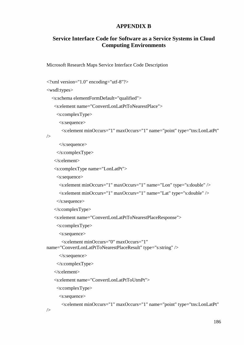
186
APPENDIX B
Service Interface Code for Software as a Service Systems in Cloud
Computing Environments
Microsoft Research Maps Service Interface Code Description
<?xml version="1.0" encoding="utf-8"?>
<wsdl:types>
<s:schema elementFormDefault="qualified">
<s:element name="ConvertLonLatPtToNearestPlace">
<s:complexType>
<s:sequence>
<s:element minOccurs="1" maxOccurs="1" name="point" type="tns:LonLatPt"
/>
</s:sequence>
</s:complexType>
</s:element>
<s:complexType name="LonLatPt">
<s:sequence>
<s:element minOccurs="1" maxOccurs="1" name="Lon" type="s:double" />
<s:element minOccurs="1" maxOccurs="1" name="Lat" type="s:double" />
</s:sequence>
</s:complexType>
<s:element name="ConvertLonLatPtToNearestPlaceResponse">
<s:complexType>
<s:sequence>
<s:element minOccurs="0" maxOccurs="1"
name="ConvertLonLatPtToNearestPlaceResult" type="s:string" />
</s:sequence>
</s:complexType>
</s:element>
<s:element name="ConvertLonLatPtToUtmPt">
<s:complexType>
<s:sequence>
<s:element minOccurs="1" maxOccurs="1" name="point" type="tns:LonLatPt"
/>

187
</s:sequence>
</s:complexType>
</s:element>
<s:element name="ConvertLonLatPtToUtmPtResponse">
<s:complexType>
<s:sequence>
<s:element minOccurs="1" maxOccurs="1"
name="ConvertLonLatPtToUtmPtResult" type="tns:UtmPt" />
</s:sequence>
</s:complexType>
</s:element>
<s:complexType name="UtmPt">
<s:sequence>
<s:element minOccurs="1" maxOccurs="1" name="Zone" type="s:int" />
<s:element minOccurs="1" maxOccurs="1" name="X" type="s:double" />
<s:element minOccurs="1" maxOccurs="1" name="Y" type="s:double" />
</s:sequence>
</s:complexType>
<s:element name="ConvertUtmPtToLonLatPt">
<s:complexType>
<s:sequence>
<s:element minOccurs="1" maxOccurs="1" name="utm" type="tns:UtmPt" />
</s:sequence>
</s:complexType>
</s:element>
<s:element name="ConvertUtmPtToLonLatPtResponse">
<s:complexType>
<s:sequence>
<s:element minOccurs="1" maxOccurs="1"
name="ConvertUtmPtToLonLatPtResult" type="tns:LonLatPt" />
</s:sequence>
</s:complexType>
</s:element>
<s:element name="ConvertPlaceToLonLatPt">
<s:complexType>
<s:sequence>
<s:element minOccurs="1" maxOccurs="1" name="place" type="tns:Place" />

188
</s:sequence>
</s:complexType>
</s:element>
<s:complexType name="Place">
<s:sequence>
<s:element minOccurs="0" maxOccurs="1" name="City" type="s:string" />
<s:element minOccurs="0" maxOccurs="1" name="State" type="s:string" />
<s:element minOccurs="0" maxOccurs="1" name="Country" type="s:string" />
</s:sequence>
</s:complexType>
<s:element name="ConvertPlaceToLonLatPtResponse">
<s:complexType>
<s:sequence>
<s:element minOccurs="1" maxOccurs="1"
name="ConvertPlaceToLonLatPtResult" type="tns:LonLatPt" />
</s:sequence>
</s:complexType>
</s:element>
<s:element name="CountPlacesInRect">
<s:complexType>
<s:sequence>
<s:element minOccurs="1" maxOccurs="1" name="upperleft"
type="tns:LonLatPt" />
<s:element minOccurs="1" maxOccurs="1" name="lowerright"
type="tns:LonLatPt" />
<s:element minOccurs="1" maxOccurs="1" name="ptype"
type="tns:PlaceType" />
</s:sequence>
</s:complexType>
</s:element>
<s:simpleType name="PlaceType">
<s:restriction base="s:string">
<s:enumeration value="UnknownPlaceType" />
<s:enumeration value="AirRailStation" />
<s:enumeration value="BayGulf" />
<s:enumeration value="CapePeninsula" />
<s:enumeration value="CityTown" />

189
<s:enumeration value="HillMountain" />
<s:enumeration value="Island" />
<s:enumeration value="Lake" />
<s:enumeration value="OtherLandFeature" />
<s:enumeration value="OtherWaterFeature" />
<s:enumeration value="ParkBeach" />
<s:enumeration value="PointOfInterest" />
<s:enumeration value="River" />
</s:restriction>
</s:simpleType>
<s:element name="CountPlacesInRectResponse">
<s:complexType>
<s:sequence>
<s:element minOccurs="1" maxOccurs="1" name="CountPlacesInRectResult"
type="s:int" />
</s:sequence>
</s:complexType>
</s:element>
<s:element name="GetAreaFromPt">
<s:complexType>
<s:sequence>
<s:element minOccurs="1" maxOccurs="1" name="center" type="tns:LonLatPt"
/>
<s:element minOccurs="1" maxOccurs="1" name="theme" type="s:int" />
<s:element minOccurs="1" maxOccurs="1" name="scale" type="tns:Scale" />
<s:element minOccurs="1" maxOccurs="1" name="displayPixWidth"
type="s:int" />
<s:element minOccurs="1" maxOccurs="1" name="displayPixHeight"
type="s:int" />
</s:sequence>
</s:complexType>
</s:element>
<s:simpleType name="Scale">
<s:restriction base="s:string">
<s:enumeration value="Scale1mm" />
<s:enumeration value="Scale2mm" />
<s:enumeration value="Scale4mm" />

190
<s:enumeration value="Scale8mm" />
<s:enumeration value="Scale16mm" />
<s:enumeration value="Scale32mm" />
<s:enumeration value="Scale63mm" />
<s:enumeration value="Scale125mm" />
<s:enumeration value="Scale250mm" />
<s:enumeration value="Scale500mm" />
<s:enumeration value="Scale1m" />
<s:enumeration value="Scale2m" />
<s:enumeration value="Scale4m" />
<s:enumeration value="Scale8m" />
<s:enumeration value="Scale16m" />
<s:enumeration value="Scale32m" />
<s:enumeration value="Scale64m" />
<s:enumeration value="Scale128m" />
<s:enumeration value="Scale256m" />
<s:enumeration value="Scale512m" />
<s:enumeration value="Scale1km" />
<s:enumeration value="Scale2km" />
<s:enumeration value="Scale4km" />
<s:enumeration value="Scale8km" />
<s:enumeration value="Scale16km" />
<s:enumeration value="Scale32km" />
<s:enumeration value="Scale64km" />
<s:enumeration value="Scale128km" />
<s:enumeration value="Scale256km" />
<s:enumeration value="Scale512km" />
<s:enumeration value="Scale1024km" />
<s:enumeration value="Scale2048km" />
</s:restriction>
</s:simpleType>
<s:element name="GetAreaFromPtResponse">
<s:complexType>
<s:sequence>
<s:element minOccurs="1" maxOccurs="1" name="GetAreaFromPtResult"
type="tns:AreaBoundingBox" />
</s:sequence>

191
</s:complexType>
</s:element>
<s:complexType name="AreaBoundingBox">
<s:sequence>
<s:element minOccurs="1" maxOccurs="1" name="NorthWest"
type="tns:AreaCoordinate" />
<s:element minOccurs="1" maxOccurs="1" name="NorthEast"
type="tns:AreaCoordinate" />
<s:element minOccurs="1" maxOccurs="1" name="SouthWest"
type="tns:AreaCoordinate" />
<s:element minOccurs="1" maxOccurs="1" name="SouthEast"
type="tns:AreaCoordinate" />
<s:element minOccurs="1" maxOccurs="1" name="Center"
type="tns:AreaCoordinate" />
<s:element minOccurs="0" maxOccurs="1" name="NearestPlace" type="s:string"
/>
<s:element minOccurs="0" maxOccurs="1" name="OverlappingThemeInfos"
type="tns:ArrayOfOverlappingThemeInfo" />
</s:sequence>
</s:complexType>
<s:complexType name="AreaCoordinate">
<s:sequence>
<s:element minOccurs="1" maxOccurs="1" name="TileMeta"
type="tns:TileMeta" />
<s:element minOccurs="1" maxOccurs="1" name="Offset"
type="tns:LonLatPtOffset" />
</s:sequence>
</s:complexType>
<s:complexType name="TileMeta">
<s:sequence>
<s:element minOccurs="1" maxOccurs="1" name="Id" type="tns:TileId" />
<s:element minOccurs="1" maxOccurs="1" name="TileExists" type="s:boolean"
/>
<s:element minOccurs="1" maxOccurs="1" name="NorthWest"
type="tns:LonLatPt" />
<s:element minOccurs="1" maxOccurs="1" name="NorthEast"
type="tns:LonLatPt" />
<s:element minOccurs="1" maxOccurs="1" name="SouthWest"
type="tns:LonLatPt" />
<s:element minOccurs="1" maxOccurs="1" name="SouthEast"
type="tns:LonLatPt" />
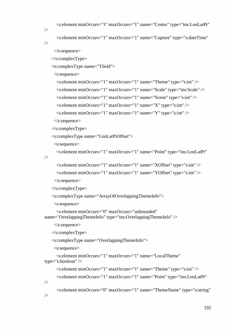
192
<s:element minOccurs="1" maxOccurs="1" name="Center" type="tns:LonLatPt"
/>
<s:element minOccurs="1" maxOccurs="1" name="Capture" type="s:dateTime"
/>
</s:sequence>
</s:complexType>
<s:complexType name="TileId">
<s:sequence>
<s:element minOccurs="1" maxOccurs="1" name="Theme" type="s:int" />
<s:element minOccurs="1" maxOccurs="1" name="Scale" type="tns:Scale" />
<s:element minOccurs="1" maxOccurs="1" name="Scene" type="s:int" />
<s:element minOccurs="1" maxOccurs="1" name="X" type="s:int" />
<s:element minOccurs="1" maxOccurs="1" name="Y" type="s:int" />
</s:sequence>
</s:complexType>
<s:complexType name="LonLatPtOffset">
<s:sequence>
<s:element minOccurs="1" maxOccurs="1" name="Point" type="tns:LonLatPt"
/>
<s:element minOccurs="1" maxOccurs="1" name="XOffset" type="s:int" />
<s:element minOccurs="1" maxOccurs="1" name="YOffset" type="s:int" />
</s:sequence>
</s:complexType>
<s:complexType name="ArrayOfOverlappingThemeInfo">
<s:sequence>
<s:element minOccurs="0" maxOccurs="unbounded"
name="OverlappingThemeInfo" type="tns:OverlappingThemeInfo" />
</s:sequence>
</s:complexType>
<s:complexType name="OverlappingThemeInfo">
<s:sequence>
<s:element minOccurs="1" maxOccurs="1" name="LocalTheme"
type="s:boolean" />
<s:element minOccurs="1" maxOccurs="1" name="Theme" type="s:int" />
<s:element minOccurs="1" maxOccurs="1" name="Point" type="tns:LonLatPt"
/>
<s:element minOccurs="0" maxOccurs="1" name="ThemeName" type="s:string"
/>

193
<s:element minOccurs="1" maxOccurs="1" name="Capture" type="s:dateTime"
/>
<s:element minOccurs="1" maxOccurs="1" name="ProjectionId"
type="tns:ProjectionType" />
<s:element minOccurs="1" maxOccurs="1" name="LoScale" type="tns:Scale" />
<s:element minOccurs="1" maxOccurs="1" name="HiScale" type="tns:Scale" />
<s:element minOccurs="0" maxOccurs="1" name="Url" type="s:string" />
</s:sequence>
</s:complexType>
<s:simpleType name="ProjectionType">
<s:restriction base="s:string">
<s:enumeration value="Geographic" />
<s:enumeration value="UtmNad27" />
<s:enumeration value="UtmNad83" />
</s:restriction>
</s:simpleType>
<s:element name="GetAreaFromRect">
<s:complexType>
<s:sequence>
<s:element minOccurs="1" maxOccurs="1" name="upperLeft"
type="tns:LonLatPt" />
<s:element minOccurs="1" maxOccurs="1" name="lowerRight"
type="tns:LonLatPt" />
<s:element minOccurs="1" maxOccurs="1" name="theme" type="s:int" />
<s:element minOccurs="1" maxOccurs="1" name="scale" type="tns:Scale" />
</s:sequence>
</s:complexType>
</s:element>
<s:element name="GetAreaFromRectResponse">
<s:complexType>
<s:sequence>
<s:element minOccurs="1" maxOccurs="1" name="GetAreaFromRectResult"
type="tns:AreaBoundingBox" />
</s:sequence>
</s:complexType>
</s:element>
<s:element name="GetAreaFromTileId">
<s:complexType>

194
<s:sequence>
<s:element minOccurs="1" maxOccurs="1" name="id" type="tns:TileId" />
<s:element minOccurs="1" maxOccurs="1" name="displayPixWidth"
type="s:int" />
<s:element minOccurs="1" maxOccurs="1" name="displayPixHeight"
type="s:int" />
</s:sequence>
</s:complexType>
</s:element>
<s:element name="GetAreaFromTileIdResponse">
<s:complexType>
<s:sequence>
<s:element minOccurs="1" maxOccurs="1" name="GetAreaFromTileIdResult"
type="tns:AreaBoundingBox" />
</s:sequence>
</s:complexType>
</s:element>
<s:element name="GetLatLonMetrics">
<s:complexType>
<s:sequence>
<s:element minOccurs="1" maxOccurs="1" name="point" type="tns:LonLatPt"
/>
</s:sequence>
</s:complexType>
</s:element>
<s:element name="GetLatLonMetricsResponse">
<s:complexType>
<s:sequence>
<s:element minOccurs="0" maxOccurs="1" name="GetLatLonMetricsResult"
type="tns:ArrayOfThemeBoundingBox" />
</s:sequence>
</s:complexType>
</s:element>
<s:complexType name="ArrayOfThemeBoundingBox">
<s:sequence>
<s:element minOccurs="0" maxOccurs="unbounded"
name="ThemeBoundingBox" type="tns:ThemeBoundingBox" />
</s:sequence>

195
</s:complexType>
<s:complexType name="ThemeBoundingBox">
<s:sequence>
<s:element minOccurs="1" maxOccurs="1" name="Theme" type="s:int" />
<s:element minOccurs="0" maxOccurs="1" name="ThemeName" type="s:string"
/>
<s:element minOccurs="1" maxOccurs="1" name="Sparseness" type="s:int" />
<s:element minOccurs="1" maxOccurs="1" name="LoScale" type="tns:Scale" />
<s:element minOccurs="1" maxOccurs="1" name="HiScale" type="tns:Scale" />
<s:element minOccurs="1" maxOccurs="1" name="ProjectionId"
type="tns:ProjectionType" />
<s:element minOccurs="0" maxOccurs="1" name="ProjectionName"
type="s:string" />
<s:element minOccurs="1" maxOccurs="1" name="WestLongitude"
type="s:double" />
<s:element minOccurs="1" maxOccurs="1" name="NorthLatitude"
type="s:double" />
<s:element minOccurs="1" maxOccurs="1" name="EastLongitude"
type="s:double" />
<s:element minOccurs="1" maxOccurs="1" name="SouthLatitude"
type="s:double" />
</s:sequence>
</s:complexType>
<s:element name="GetPlaceFacts">
<s:complexType>
<s:sequence>
<s:element minOccurs="1" maxOccurs="1" name="place" type="tns:Place" />
</s:sequence>
</s:complexType>
</s:element>
<s:element name="GetPlaceFactsResponse">
<s:complexType>
<s:sequence>
<s:element minOccurs="1" maxOccurs="1" name="GetPlaceFactsResult"
type="tns:PlaceFacts" />
</s:sequence>
</s:complexType>
</s:element>
<s:complexType name="PlaceFacts">

196
<s:sequence>
<s:element minOccurs="1" maxOccurs="1" name="Place" type="tns:Place" />
<s:element minOccurs="1" maxOccurs="1" name="Center" type="tns:LonLatPt"
/>
<s:element minOccurs="1" maxOccurs="1" name="AvailableThemeMask"
type="s:int" />
<s:element minOccurs="1" maxOccurs="1" name="PlaceTypeId"
type="tns:PlaceType" />
<s:element minOccurs="1" maxOccurs="1" name="Population" type="s:int" />
</s:sequence>
</s:complexType>
<s:element name="GetPlaceList">
<s:complexType>
<s:sequence>
<s:element minOccurs="0" maxOccurs="1" name="placeName" type="s:string"
/>
<s:element minOccurs="1" maxOccurs="1" name="MaxItems" type="s:int" />
<s:element minOccurs="1" maxOccurs="1" name="imagePresence"
type="s:boolean" />
</s:sequence>
</s:complexType>
</s:element>
<s:element name="GetPlaceListResponse">
<s:complexType>
<s:sequence>
<s:element minOccurs="0" maxOccurs="1" name="GetPlaceListResult"
type="tns:ArrayOfPlaceFacts" />
</s:sequence>
</s:complexType>
</s:element>
<s:complexType name="ArrayOfPlaceFacts">
<s:sequence>
<s:element minOccurs="0" maxOccurs="unbounded" name="PlaceFacts"
type="tns:PlaceFacts" />
</s:sequence>
</s:complexType>
<s:element name="GetPlaceListInRect">
<s:complexType>

197
<s:sequence>
<s:element minOccurs="1" maxOccurs="1" name="upperleft"
type="tns:LonLatPt" />
<s:element minOccurs="1" maxOccurs="1" name="lowerright"
type="tns:LonLatPt" />
<s:element minOccurs="1" maxOccurs="1" name="ptype"
type="tns:PlaceType" />
<s:element minOccurs="1" maxOccurs="1" name="MaxItems" type="s:int" />
</s:sequence>
</s:complexType>
</s:element>
<s:element name="GetPlaceListInRectResponse">
<s:complexType>
<s:sequence>
<s:element minOccurs="0" maxOccurs="1" name="GetPlaceListInRectResult"
type="tns:ArrayOfPlaceFacts" />
</s:sequence>
</s:complexType>
</s:element>
<s:element name="GetTheme">
<s:complexType>
<s:sequence>
<s:element minOccurs="1" maxOccurs="1" name="theme" type="s:int" />
</s:sequence>
</s:complexType>
</s:element>
<s:element name="GetThemeResponse">
<s:complexType>
<s:sequence>
<s:element minOccurs="1" maxOccurs="1" name="GetThemeResult"
type="tns:ThemeInfo" />
</s:sequence>
</s:complexType>
</s:element>
<s:complexType name="ThemeInfo">
<s:sequence>
<s:element minOccurs="1" maxOccurs="1" name="Theme" type="s:int" />
<s:element minOccurs="0" maxOccurs="1" name="Name" type="s:string" />

198
<s:element minOccurs="0" maxOccurs="1" name="Description" type="s:string"
/>
<s:element minOccurs="0" maxOccurs="1" name="Supplier" type="s:string" />
<s:element minOccurs="1" maxOccurs="1" name="LoScale" type="tns:Scale" />
<s:element minOccurs="1" maxOccurs="1" name="HiScale" type="tns:Scale" />
<s:element minOccurs="1" maxOccurs="1" name="ProjectionId"
type="tns:ProjectionType" />
<s:element minOccurs="0" maxOccurs="1" name="ProjectionName"
type="s:string" />
<s:element minOccurs="0" maxOccurs="1" name="CopyrightNotice"
type="s:string" />
</s:sequence>
</s:complexType>
<s:element name="GetTileMetaFromLonLatPt">
<s:complexType>
<s:sequence>
<s:element minOccurs="1" maxOccurs="1" name="point" type="tns:LonLatPt"
/>
<s:element minOccurs="1" maxOccurs="1" name="theme" type="s:int" />
<s:element minOccurs="1" maxOccurs="1" name="scale" type="tns:Scale" />
</s:sequence>
</s:complexType>
</s:element>
<s:element name="GetTileMetaFromLonLatPtResponse">
<s:complexType>
<s:sequence>
<s:element minOccurs="1" maxOccurs="1"
name="GetTileMetaFromLonLatPtResult" type="tns:TileMeta" />
</s:sequence>
</s:complexType>
</s:element>
<s:element name="GetTileMetaFromTileId">
<s:complexType>
<s:sequence>
<s:element minOccurs="1" maxOccurs="1" name="id" type="tns:TileId" />
</s:sequence>
</s:complexType>
</s:element>

199
<s:element name="GetTileMetaFromTileIdResponse">
<s:complexType>
<s:sequence>
<s:element minOccurs="1" maxOccurs="1"
name="GetTileMetaFromTileIdResult" type="tns:TileMeta" />
</s:sequence>
</s:complexType>
</s:element>
<s:element name="GetTile">
<s:complexType>
<s:sequence>
<s:element minOccurs="1" maxOccurs="1" name="id" type="tns:TileId" />
</s:sequence>
</s:complexType>
</s:element>
<s:element name="GetTileResponse">
<s:complexType>
<s:sequence>
<s:element minOccurs="0" maxOccurs="1" name="GetTileResult"
type="s:base64Binary" />
</s:sequence>
</s:complexType>
</s:element>
</s:schema>
</wsdl:types>
<wsdl:message name="ConvertLonLatPtToNearestPlaceSoapIn">
<wsdl:part name="parameters" element="tns:ConvertLonLatPtToNearestPlace" />
</wsdl:message>
<wsdl:message name="ConvertLonLatPtToNearestPlaceSoapOut">
<wsdl:part name="parameters"
element="tns:ConvertLonLatPtToNearestPlaceResponse" />
</wsdl:message>
<wsdl:message name="ConvertLonLatPtToUtmPtSoapIn">
<wsdl:part name="parameters" element="tns:ConvertLonLatPtToUtmPt" />
</wsdl:message>
<wsdl:message name="ConvertLonLatPtToUtmPtSoapOut">
<wsdl:part name="parameters" element="tns:ConvertLonLatPtToUtmPtResponse" />

200
</wsdl:message>
<wsdl:message name="ConvertUtmPtToLonLatPtSoapIn">
<wsdl:part name="parameters" element="tns:ConvertUtmPtToLonLatPt" />
</wsdl:message>
<wsdl:message name="ConvertUtmPtToLonLatPtSoapOut">
<wsdl:part name="parameters" element="tns:ConvertUtmPtToLonLatPtResponse" />
</wsdl:message>
<wsdl:message name="ConvertPlaceToLonLatPtSoapIn">
<wsdl:part name="parameters" element="tns:ConvertPlaceToLonLatPt" />
</wsdl:message>
<wsdl:message name="ConvertPlaceToLonLatPtSoapOut">
<wsdl:part name="parameters" element="tns:ConvertPlaceToLonLatPtResponse" />
</wsdl:message>
<wsdl:message name="CountPlacesInRectSoapIn">
<wsdl:part name="parameters" element="tns:CountPlacesInRect" />
</wsdl:message>
<wsdl:message name="CountPlacesInRectSoapOut">
<wsdl:part name="parameters" element="tns:CountPlacesInRectResponse" />
</wsdl:message>
<wsdl:message name="GetAreaFromPtSoapIn">
<wsdl:part name="parameters" element="tns:GetAreaFromPt" />
</wsdl:message>
<wsdl:message name="GetAreaFromPtSoapOut">
<wsdl:part name="parameters" element="tns:GetAreaFromPtResponse" />
</wsdl:message>
<wsdl:message name="GetAreaFromRectSoapIn">
<wsdl:part name="parameters" element="tns:GetAreaFromRect" />
</wsdl:message>
<wsdl:message name="GetAreaFromRectSoapOut">
<wsdl:part name="parameters" element="tns:GetAreaFromRectResponse" />
</wsdl:message>
<wsdl:message name="GetAreaFromTileIdSoapIn">
<wsdl:part name="parameters" element="tns:GetAreaFromTileId" />
</wsdl:message>
<wsdl:message name="GetAreaFromTileIdSoapOut">
<wsdl:part name="parameters" element="tns:GetAreaFromTileIdResponse" />

201
</wsdl:message>
<wsdl:message name="GetLatLonMetricsSoapIn">
<wsdl:part name="parameters" element="tns:GetLatLonMetrics" />
</wsdl:message>
<wsdl:message name="GetLatLonMetricsSoapOut">
<wsdl:part name="parameters" element="tns:GetLatLonMetricsResponse" />
</wsdl:message>
<wsdl:message name="GetPlaceFactsSoapIn">
<wsdl:part name="parameters" element="tns:GetPlaceFacts" />
</wsdl:message>
<wsdl:message name="GetPlaceFactsSoapOut">
<wsdl:part name="parameters" element="tns:GetPlaceFactsResponse" />
</wsdl:message>
<wsdl:message name="GetPlaceListSoapIn">
<wsdl:part name="parameters" element="tns:GetPlaceList" />
</wsdl:message>
<wsdl:message name="GetPlaceListSoapOut">
<wsdl:part name="parameters" element="tns:GetPlaceListResponse" />
</wsdl:message>
<wsdl:message name="GetPlaceListInRectSoapIn">
<wsdl:part name="parameters" element="tns:GetPlaceListInRect" />
</wsdl:message>
<wsdl:message name="GetPlaceListInRectSoapOut">
<wsdl:part name="parameters" element="tns:GetPlaceListInRectResponse" />
</wsdl:message>
<wsdl:message name="GetThemeSoapIn">
<wsdl:part name="parameters" element="tns:GetTheme" />
</wsdl:message>
<wsdl:message name="GetThemeSoapOut">
<wsdl:part name="parameters" element="tns:GetThemeResponse" />
</wsdl:message>
<wsdl:message name="GetTileMetaFromLonLatPtSoapIn">
<wsdl:part name="parameters" element="tns:GetTileMetaFromLonLatPt" />
</wsdl:message>
<wsdl:message name="GetTileMetaFromLonLatPtSoapOut">
<wsdl:part name="parameters" element="tns:GetTileMetaFromLonLatPtResponse"
/>

202
</wsdl:message>
<wsdl:message name="GetTileMetaFromTileIdSoapIn">
<wsdl:part name="parameters" element="tns:GetTileMetaFromTileId" />
</wsdl:message>
<wsdl:message name="GetTileMetaFromTileIdSoapOut">
<wsdl:part name="parameters" element="tns:GetTileMetaFromTileIdResponse" />
</wsdl:message>
<wsdl:message name="GetTileSoapIn">
<wsdl:part name="parameters" element="tns:GetTile" />
</wsdl:message>
<wsdl:message name="GetTileSoapOut">
<wsdl:part name="parameters" element="tns:GetTileResponse" />
</wsdl:message>
<wsdl:portType name="TerraServiceSoap">
<wsdl:operation name="ConvertLonLatPtToNearestPlace">
<wsdl:input message="tns:ConvertLonLatPtToNearestPlaceSoapIn" />
<wsdl:output message="tns:ConvertLonLatPtToNearestPlaceSoapOut" />
</wsdl:operation>
<wsdl:operation name="ConvertLonLatPtToUtmPt">
<wsdl:input message="tns:ConvertLonLatPtToUtmPtSoapIn" />
<wsdl:output message="tns:ConvertLonLatPtToUtmPtSoapOut" />
</wsdl:operation>
<wsdl:operation name="ConvertUtmPtToLonLatPt">
<wsdl:input message="tns:ConvertUtmPtToLonLatPtSoapIn" />
<wsdl:output message="tns:ConvertUtmPtToLonLatPtSoapOut" />
</wsdl:operation>
<wsdl:operation name="ConvertPlaceToLonLatPt">
<wsdl:input message="tns:ConvertPlaceToLonLatPtSoapIn" />
<wsdl:output message="tns:ConvertPlaceToLonLatPtSoapOut" />
</wsdl:operation>
<wsdl:operation name="CountPlacesInRect">
<wsdl:input message="tns:CountPlacesInRectSoapIn" />
<wsdl:output message="tns:CountPlacesInRectSoapOut" />
</wsdl:operation>
<wsdl:operation name="GetAreaFromPt">
<wsdl:input message="tns:GetAreaFromPtSoapIn" />

203
<wsdl:output message="tns:GetAreaFromPtSoapOut" />
</wsdl:operation>
<wsdl:operation name="GetAreaFromRect">
<wsdl:input message="tns:GetAreaFromRectSoapIn" />
<wsdl:output message="tns:GetAreaFromRectSoapOut" />
</wsdl:operation>
<wsdl:operation name="GetAreaFromTileId">
<wsdl:input message="tns:GetAreaFromTileIdSoapIn" />
<wsdl:output message="tns:GetAreaFromTileIdSoapOut" />
</wsdl:operation>
<wsdl:operation name="GetLatLonMetrics">
<wsdl:input message="tns:GetLatLonMetricsSoapIn" />
<wsdl:output message="tns:GetLatLonMetricsSoapOut" />
</wsdl:operation>
<wsdl:operation name="GetPlaceFacts">
<wsdl:input message="tns:GetPlaceFactsSoapIn" />
<wsdl:output message="tns:GetPlaceFactsSoapOut" />
</wsdl:operation>
<wsdl:operation name="GetPlaceList">
<wsdl:input message="tns:GetPlaceListSoapIn" />
<wsdl:output message="tns:GetPlaceListSoapOut" />
</wsdl:operation>
<wsdl:operation name="GetPlaceListInRect">
<wsdl:input message="tns:GetPlaceListInRectSoapIn" />
<wsdl:output message="tns:GetPlaceListInRectSoapOut" />
</wsdl:operation>
<wsdl:operation name="GetTheme">
<wsdl:input message="tns:GetThemeSoapIn" />
<wsdl:output message="tns:GetThemeSoapOut" />
</wsdl:operation>
<wsdl:operation name="GetTileMetaFromLonLatPt">
<wsdl:input message="tns:GetTileMetaFromLonLatPtSoapIn" />
<wsdl:output message="tns:GetTileMetaFromLonLatPtSoapOut" />
</wsdl:operation>
<wsdl:operation name="GetTileMetaFromTileId">
<wsdl:input message="tns:GetTileMetaFromTileIdSoapIn" />

204
<wsdl:output message="tns:GetTileMetaFromTileIdSoapOut" />
</wsdl:operation>
<wsdl:operation name="GetTile">
<wsdl:input message="tns:GetTileSoapIn" />
<wsdl:output message="tns:GetTileSoapOut" />
</wsdl:operation>
</wsdl:portType>
<wsdl:binding name="TerraServiceSoap" type="tns:TerraServiceSoap">
<wsdl:operation name="ConvertLonLatPtToNearestPlace">
<soap:operation
<wsdl:input>
<soap:body use="literal" />
</wsdl:input>
<wsdl:output>
<soap:body use="literal" />
</wsdl:output>
</wsdl:operation>
<wsdl:operation name="ConvertLonLatPtToUtmPt">
<wsdl:input>
<soap:body use="literal" />
</wsdl:input>
<wsdl:output>
<soap:body use="literal" />
</wsdl:output>
</wsdl:operation>
<wsdl:operation name="ConvertUtmPtToLonLatPt">
<wsdl:input>
<soap:body use="literal" />
</wsdl:input>
<wsdl:output>
<soap:body use="literal" />
</wsdl:output>
</wsdl:operation>
<wsdl:operation name="ConvertPlaceToLonLatPt">
<wsdl:input>
<soap:body use="literal" />

205
</wsdl:input>
<wsdl:output>
<soap:body use="literal" />
</wsdl:output>
</wsdl:operation>
<wsdl:operation name="CountPlacesInRect">
<wsdl:input>
<soap:body use="literal" />
</wsdl:input>
<wsdl:output>
<soap:body use="literal" />
</wsdl:output>
</wsdl:operation>
<wsdl:operation name="GetAreaFromPt">
<wsdl:input>
<soap:body use="literal" />
</wsdl:input>
<wsdl:output>
<soap:body use="literal" />
</wsdl:output>
</wsdl:operation>
<wsdl:operation name="GetAreaFromRect">
<wsdl:input>
<soap:body use="literal" />
</wsdl:input>
<wsdl:output>
<soap:body use="literal" />
</wsdl:output>
</wsdl:operation>
<wsdl:operation name="GetAreaFromTileId">
<wsdl:input>
<soap:body use="literal" />
</wsdl:input>
<wsdl:output>
<soap:body use="literal" />
</wsdl:output>

206
</wsdl:operation>
<wsdl:operation name="GetLatLonMetrics">
<wsdl:input>
<soap:body use="literal" />
</wsdl:input>
<wsdl:output>
<soap:body use="literal" />
</wsdl:output>
</wsdl:operation>
<wsdl:operation name="GetPlaceFacts">
<wsdl:input>
<soap:body use="literal" />
</wsdl:input>
<wsdl:output>
<soap:body use="literal" />
</wsdl:output>
</wsdl:operation>
<wsdl:operation name="GetPlaceList">
<wsdl:input>
<soap:body use="literal" />
</wsdl:input>
<wsdl:output>
<soap:body use="literal" />
</wsdl:output>
</wsdl:operation>
<wsdl:operation name="GetPlaceListInRect">
<wsdl:input>
<soap:body use="literal" />
</wsdl:input>
<wsdl:output>
<soap:body use="literal" />
</wsdl:output>
</wsdl:operation>
<wsdl:operation name="GetTheme">
<wsdl:input>
<soap:body use="literal" />

207
</wsdl:input>
<wsdl:output>
<soap:body use="literal" />
</wsdl:output>
</wsdl:operation>
<wsdl:operation name="GetTileMetaFromLonLatPt">
<wsdl:input>
<soap:body use="literal" />
</wsdl:input>
<wsdl:output>
<soap:body use="literal" />
</wsdl:output>
</wsdl:operation>
<wsdl:operation name="GetTileMetaFromTileId">
<wsdl:input>
<soap:body use="literal" />
</wsdl:input>
<wsdl:output>
<soap:body use="literal" />
</wsdl:output>
</wsdl:operation>
<wsdl:operation name="GetTile">
<wsdl:input>
<soap:body use="literal" />
</wsdl:input>
<wsdl:output>
<soap:body use="literal" />
</wsdl:output>
</wsdl:operation>
</wsdl:binding>
<wsdl:binding name="TerraServiceSoap12" type="tns:TerraServiceSoap">
<wsdl:operation name="ConvertLonLatPtToNearestPlace">
<wsdl:input>
<soap12:body use="literal" />
</wsdl:input>
<wsdl:output>

208
<soap12:body use="literal" />
</wsdl:output>
</wsdl:operation>
<wsdl:operation name="ConvertLonLatPtToUtmPt">
<wsdl:input>
<soap12:body use="literal" />
</wsdl:input>
<wsdl:output>
<soap12:body use="literal" />
</wsdl:output>
</wsdl:operation>
<wsdl:operation name="ConvertUtmPtToLonLatPt">
<wsdl:input>
<soap12:body use="literal" />
</wsdl:input>
<wsdl:output>
<soap12:body use="literal" />
</wsdl:output>
</wsdl:operation>
<wsdl:operation name="ConvertPlaceToLonLatPt">
<wsdl:input>
<soap12:body use="literal" />
</wsdl:input>
<wsdl:output>
<soap12:body use="literal" />
</wsdl:output>
</wsdl:operation>
<wsdl:operation name="CountPlacesInRect">
<wsdl:input>
<soap12:body use="literal" />
</wsdl:input>
<wsdl:output>
<soap12:body use="literal" />
</wsdl:output>
</wsdl:operation>
<wsdl:operation name="GetAreaFromPt">

209
<wsdl:input>
<soap12:body use="literal" />
</wsdl:input>
<wsdl:output>
<soap12:body use="literal" />
</wsdl:output>
</wsdl:operation>
<wsdl:operation name="GetAreaFromRect">
<wsdl:input>
<soap12:body use="literal" />
</wsdl:input>
<wsdl:output>
<soap12:body use="literal" />
</wsdl:output>
</wsdl:operation>
<wsdl:operation name="GetAreaFromTileId">
<wsdl:input>
<soap12:body use="literal" />
</wsdl:input>
<wsdl:output>
<soap12:body use="literal" />
</wsdl:output>
</wsdl:operation>
<wsdl:operation name="GetLatLonMetrics">
<wsdl:input>
<soap12:body use="literal" />
</wsdl:input>
<wsdl:output>
<soap12:body use="literal" />
</wsdl:output>
</wsdl:operation>
<wsdl:operation name="GetPlaceFacts">
<wsdl:input>
<soap12:body use="literal" />
</wsdl:input>
<wsdl:output>

210
<soap12:body use="literal" />
</wsdl:output>
</wsdl:operation>
<wsdl:operation name="GetPlaceList">
<wsdl:input>
<soap12:body use="literal" />
</wsdl:input>
<wsdl:output>
<soap12:body use="literal" />
</wsdl:output>
</wsdl:operation>
<wsdl:operation name="GetPlaceListInRect">
<wsdl:input>
<soap12:body use="literal" />
</wsdl:input>
<wsdl:output>
<soap12:body use="literal" />
</wsdl:output>
</wsdl:operation>
<wsdl:operation name="GetTheme">
<wsdl:input>
<soap12:body use="literal" />
</wsdl:input>
<wsdl:output>
<soap12:body use="literal" />
</wsdl:output>
</wsdl:operation>
<wsdl:operation name="GetTileMetaFromLonLatPt">
<wsdl:input>
<soap12:body use="literal" />
</wsdl:input>
<wsdl:output>
<soap12:body use="literal" />
</wsdl:output>
</wsdl:operation>
<wsdl:operation name="GetTileMetaFromTileId">
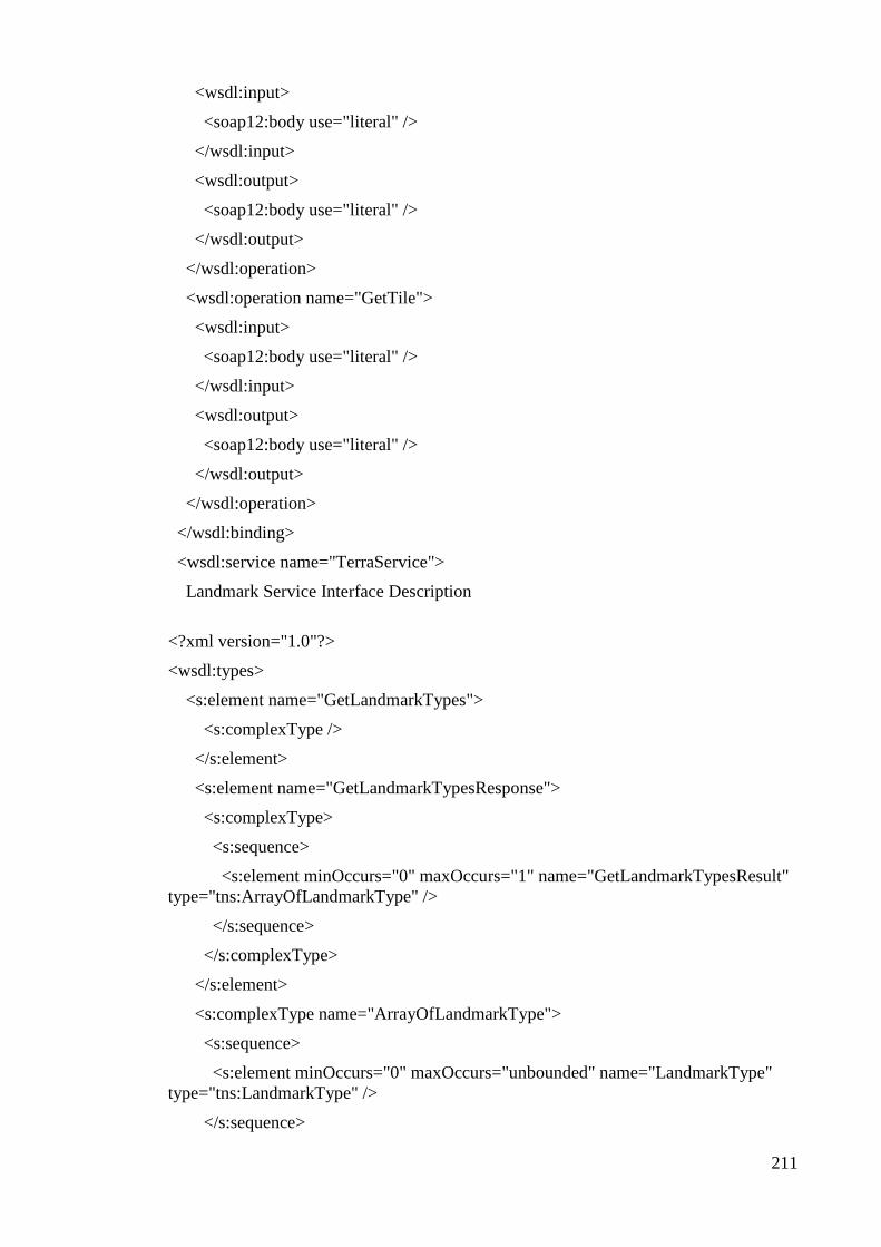
211
<wsdl:input>
<soap12:body use="literal" />
</wsdl:input>
<wsdl:output>
<soap12:body use="literal" />
</wsdl:output>
</wsdl:operation>
<wsdl:operation name="GetTile">
<wsdl:input>
<soap12:body use="literal" />
</wsdl:input>
<wsdl:output>
<soap12:body use="literal" />
</wsdl:output>
</wsdl:operation>
</wsdl:binding>
<wsdl:service name="TerraService">
Landmark Service Interface Description
<?xml version="1.0"?>
<wsdl:types>
<s:element name="GetLandmarkTypes">
<s:complexType />
</s:element>
<s:element name="GetLandmarkTypesResponse">
<s:complexType>
<s:sequence>
<s:element minOccurs="0" maxOccurs="1" name="GetLandmarkTypesResult"
type="tns:ArrayOfLandmarkType" />
</s:sequence>
</s:complexType>
</s:element>
<s:complexType name="ArrayOfLandmarkType">
<s:sequence>
<s:element minOccurs="0" maxOccurs="unbounded" name="LandmarkType"
type="tns:LandmarkType" />
</s:sequence>

212
</s:complexType>
<s:complexType name="LandmarkType">
<s:sequence>
<s:element minOccurs="1" maxOccurs="1" name="ShapeType"
type="tns:ShapeType" />
<s:element minOccurs="0" maxOccurs="1" name="Type" type="s:string" />
</s:sequence>
</s:complexType>
<s:simpleType name="ShapeType">
<s:restriction base="s:string">
<s:enumeration value="Null" />
<s:enumeration value="Point" />
<s:enumeration value="PolyLine" />
<s:enumeration value="Polygon" />
</s:restriction>
</s:simpleType>
<s:element name="CountOfLandmarkPointsByRect">
<s:complexType>
<s:sequence>
<s:element minOccurs="1" maxOccurs="1" name="rect"
type="tns:BoundingRect" />
<s:element minOccurs="0" maxOccurs="1" name="types"
type="tns:ArrayOfString" />
</s:sequence>
</s:complexType>
</s:element>
<s:complexType name="BoundingRect">
<s:sequence>
<s:element minOccurs="1" maxOccurs="1" name="UpperLeft"
type="tns:LonLatPt" />
<s:element minOccurs="1" maxOccurs="1" name="LowerRight"
type="tns:LonLatPt" />
</s:sequence>
</s:complexType>
<s:complexType name="LonLatPt">
<s:sequence>
<s:element minOccurs="1" maxOccurs="1" name="Lon" type="s:double" />
<s:element minOccurs="1" maxOccurs="1" name="Lat" type="s:double" />

213
</s:sequence>
</s:complexType>
<s:complexType name="ArrayOfString">
<s:sequence>
<s:element minOccurs="0" maxOccurs="unbounded" name="string"
nillable="true" type="s:string" />
</s:sequence>
</s:complexType>
<s:element name="CountOfLandmarkPointsByRectResponse">
<s:complexType>
<s:sequence>
<s:element minOccurs="1" maxOccurs="1"
name="CountOfLandmarkPointsByRectResult" type="s:int" />
</s:sequence>
</s:complexType>
</s:element>
<s:element name="GetLandmarkPointsByRect">
<s:complexType>
<s:sequence>
<s:element minOccurs="1" maxOccurs="1" name="rect"
type="tns:BoundingRect" />
<s:element minOccurs="0" maxOccurs="1" name="types"
type="tns:ArrayOfString" />
</s:sequence>
</s:complexType>
</s:element>
<s:element name="GetLandmarkPointsByRectResponse">
<s:complexType>
<s:sequence>
<s:element minOccurs="0" maxOccurs="1"
name="GetLandmarkPointsByRectResult" type="tns:ArrayOfLandmarkPoint" />
</s:sequence>
</s:complexType>
</s:element>
<s:complexType name="ArrayOfLandmarkPoint">
<s:sequence>
<s:element minOccurs="0" maxOccurs="unbounded" name="LandmarkPoint"
nillable="true" type="tns:LandmarkPoint" />
214
</s:sequence>
</s:complexType>
<s:complexType name="LandmarkPoint">
<s:complexContent mixed="false">
<s:extension base="tns:LandmarkBase">
<s:sequence>
<s:element minOccurs="1" maxOccurs="1" name="Point"
type="tns:LonLatPt" />
</s:sequence>
</s:extension>
</s:complexContent>
</s:complexType>
<s:complexType name="LandmarkBase">
<s:sequence>
<s:element minOccurs="0" maxOccurs="1" name="Type" type="s:string" />
<s:element minOccurs="0" maxOccurs="1" name="Name" type="s:string" />
<s:element minOccurs="0" maxOccurs="1" name="FipsCode" type="s:string" />
<s:element minOccurs="0" maxOccurs="1" name="TypeDescription"
type="s:string" />
<s:element minOccurs="1" maxOccurs="1" name="ShapeType"
type="tns:ShapeType" />
</s:sequence>
</s:complexType>
<s:element name="CountOfLandmarkShapesByRect">
<s:complexType>
<s:sequence>
<s:element minOccurs="1" maxOccurs="1" name="rect"
type="tns:BoundingRect" />
<s:element minOccurs="0" maxOccurs="1" name="types"
type="tns:ArrayOfString" />
</s:sequence>
</s:complexType>
</s:element>
<s:element name="CountOfLandmarkShapesByRectResponse">
<s:complexType>
<s:sequence>
<s:element minOccurs="1" maxOccurs="1"
name="CountOfLandmarkShapesByRectResult" type="s:int" />

215
</s:sequence>
</s:complexType>
</s:element>
</s:schema>
</wsdl:types>
<wsdl:message name="GetLandmarkTypesSoapIn">
<wsdl:part name="parameters" element="tns:GetLandmarkTypes" />
</wsdl:message>
<wsdl:message name="GetLandmarkTypesSoapOut">
<wsdl:part name="parameters" element="tns:GetLandmarkTypesResponse" />
</wsdl:message>
<wsdl:message name="CountOfLandmarkPointsByRectSoapIn">
<wsdl:part name="parameters" element="tns:CountOfLandmarkPointsByRect" />
</wsdl:message>
<wsdl:message name="CountOfLandmarkPointsByRectSoapOut">
<wsdl:part name="parameters"
element="tns:CountOfLandmarkPointsByRectResponse" />
</wsdl:message>
<wsdl:message name="GetLandmarkPointsByRectSoapIn">
<wsdl:part name="parameters" element="tns:GetLandmarkPointsByRect" />
</wsdl:message>
<wsdl:message name="GetLandmarkPointsByRectSoapOut">
<wsdl:part name="parameters" element="tns:GetLandmarkPointsByRectResponse"
/>
</wsdl:message>
<wsdl:message name="CountOfLandmarkShapesByRectSoapIn">
<wsdl:part name="parameters" element="tns:CountOfLandmarkShapesByRect" />
</wsdl:message>
<wsdl:message name="CountOfLandmarkShapesByRectSoapOut">
<wsdl:part name="parameters"
element="tns:CountOfLandmarkShapesByRectResponse" />
</wsdl:message>
<wsdl:portType name="LandmarkServiceSoap">
<wsdl:operation name="GetLandmarkTypes">
<wsdl:input message="tns:GetLandmarkTypesSoapIn" />
<wsdl:output message="tns:GetLandmarkTypesSoapOut" />
</wsdl:operation>

216
<wsdl:operation name="CountOfLandmarkPointsByRect">
<wsdl:input message="tns:CountOfLandmarkPointsByRectSoapIn" />
<wsdl:output message="tns:CountOfLandmarkPointsByRectSoapOut" />
</wsdl:operation>
<wsdl:operation name="GetLandmarkPointsByRect">
<wsdl:input message="tns:GetLandmarkPointsByRectSoapIn" />
<wsdl:output message="tns:GetLandmarkPointsByRectSoapOut" />
</wsdl:operation>
<wsdl:operation name="CountOfLandmarkShapesByRect">
<wsdl:input message="tns:CountOfLandmarkShapesByRectSoapIn" />
<wsdl:output message="tns:CountOfLandmarkShapesByRectSoapOut" />
</wsdl:operation>
</wsdl:portType>
<wsdl:binding name="LandmarkServiceSoap" type="tns:LandmarkServiceSoap">
<wsdl:input>
<soap:body use="literal" />
</wsdl:input>
<wsdl:output>
<soap:body use="literal" />
</wsdl:output>
</wsdl:operation>
<wsdl:operation name="CountOfLandmarkPointsByRect">
<wsdl:input>
<soap:body use="literal" />
</wsdl:input>
<wsdl:output>
<soap:body use="literal" />
</wsdl:output>
</wsdl:operation>
<wsdl:operation name="GetLandmarkPointsByRect">
<wsdl:input>
<soap:body use="literal" />
</wsdl:input>
<wsdl:output>
<soap:body use="literal" />
</wsdl:output>

217
</wsdl:operation>
<wsdl:operation name="CountOfLandmarkShapesByRect">
<wsdl:input>
<soap:body use="literal" />
</wsdl:input>
<wsdl:output>
<soap:body use="literal" />
</wsdl:output>
</wsdl:operation>
</wsdl:binding>
<wsdl:binding name="LandmarkServiceSoap12" type="tns:LandmarkServiceSoap">
<wsdl:operation name="GetLandmarkTypes">
<wsdl:input>
<soap12:body use="literal" />
</wsdl:input>
<wsdl:output>
<soap12:body use="literal" />
</wsdl:output>
</wsdl:operation>
<wsdl:operation name="CountOfLandmarkPointsByRect">
<wsdl:input>
<soap12:body use="literal" />
</wsdl:input>
<wsdl:output>
<soap12:body use="literal" />
</wsdl:output>
</wsdl:operation>
<wsdl:operation name="GetLandmarkPointsByRect">
<wsdl:input>
<soap12:body use="literal" />
</wsdl:input>
<wsdl:output>
<soap12:body use="literal" />
</wsdl:output>
</wsdl:operation>
<wsdl:operation name="CountOfLandmarkShapesByRect">
218
<wsdl:input>
<soap12:body use="literal" />
</wsdl:input>
<wsdl:output>
<soap12:body use="literal" />
</wsdl:output>
</wsdl:operation>
</wsdl:binding>
<wsdl:service name="LandmarkService">
<wsdl:port name="LandmarkServiceSoap" binding="tns:LandmarkServiceSoap">
</wsdl:port>
<wsdl:port name="LandmarkServiceSoap12"
binding="tns:LandmarkServiceSoap12">
</wsdl:port>
</wsdl:service>
</wsdl:definitions>
219
APPENDIX C
Ontology for the Mapping Knowledge
<?xml version="1.0"?>
<rdf:RDF
<owl:Ontology rdf:about="Map Ontology for OWL-S Model Problems">
</owl:Ontology>
<!-- Class Hierarchy -->
<owl:Class rdf:ID="Bathymetric">
<rdfs:subClassOf>
<owl:Class rdf:ID="Nautical"/>
</rdfs:subClassOf>
</owl:Class>
<owl:Class rdf:ID="Satellite">
<rdfs:subClassOf>
<owl:Class rdf:ID="Map"/>
</rdfs:subClassOf>
</owl:Class>
<owl:Class rdf:ID="Ground">
<rdfs:subClassOf rdf:resource="#Map"/>
</owl:Class>
<owl:Class rdf:ID=" ">

220
<rdfs:subClassOf>
<owl:Class rdf:ID=" "/>
</rdfs:subClassOf>
</owl:Class>
<owl:Class rdf:about="#Nautical">
<rdfs:subClassOf rdf:resource="#Map"/>
</owl:Class>
<owl:Class rdf:ID="Resolution"/>
<owl:Class rdf:ID="NAD_27">
<rdfs:subClassOf rdf:resource="#Datum"/>
</owl:Class>
<owl:Class rdf:ID="Scale"/>
<owl:Class rdf:ID="Cloud">
<rdfs:subClassOf>
<owl:Class rdf:ID="Weather"/>
</rdfs:subClassOf>
</owl:Class>
<owl:Class rdf:ID="Surface">
<rdfs:subClassOf rdf:resource="#Nautical"/>
</owl:Class>
<owl:Class rdf:ID="Street_Address">
<rdfs:subClassOf>

221
<owl:Class rdf:ID="Location"/>
</rdfs:subClassOf>
</owl:Class>
<owl:Class rdf:ID="Wind">
<rdfs:subClassOf>
<owl:Class rdf:about="#Weather"/>
</rdfs:subClassOf>
</owl:Class>
<owl:Class rdf:ID="Heightmap">
<rdfs:subClassOf rdf:resource="#Satellite"/>
</owl:Class>
<owl:Class rdf:ID="Topographic">
<rdfs:subClassOf rdf:resource="#Ground"/>
</owl:Class>
<owl:Class rdf:about="#Weather">
<rdfs:subClassOf rdf:resource="#Map"/>
</owl:Class>
<owl:Class rdf:ID="Street">
<rdfs:subClassOf rdf:resource="#Ground"/>
</owl:Class>
<owl:Class rdf:ID="Grid_Reference_System">
<rdfs:subClassOf rdf:resource="#Location"/>

222
</owl:Class>
<owl:Class rdf:ID="Loran_Time_Differential">
<rdfs:subClassOf rdf:resource="#Location"/>
</owl:Class>
<owl:Class rdf:ID="WGS_84">
<rdfs:subClassOf rdf:resource="#Datum"/>
</owl:Class>
<owl:Class rdf:ID="Thermographic">
<rdfs:subClassOf rdf:resource="#Satellite"/>
</owl:Class>
<owl:Class rdf:ID="Zip_Code">
<rdfs:subClassOf rdf:resource="#Location"/>
</owl:Class>
<owl:Class rdf:ID="Temperature">
<rdfs:subClassOf rdf:resource="#Weather"/>
</owl:Class>
<owl:Class rdf:ID="WGS_72">
<rdfs:subClassOf rdf:resource="#Datum"/>
</owl:Class>
<owl:Class rdf:ID="Flight_Paths">
<rdfs:subClassOf>
<owl:Class rdf:ID="Aeronautical"/>
223
</rdfs:subClassOf>
</owl:Class>
<owl:Class rdf:ID="Barometric">
<rdfs:subClassOf rdf:resource="#Weather"/>
</owl:Class>
<owl:Class rdf:about="#Aeronautical">
<rdfs:subClassOf rdf:resource="#Map"/>
</owl:Class>
<owl:Class rdf:ID="Latitude_Longitude">
<rdfs:subClassOf rdf:resource="#Location"/>
</owl:Class>
<owl:Class rdf:ID="Photographic">
<rdfs:subClassOf rdf:resource="#Satellite"/>
</owl:Class>
<owl:Class rdf:ID="Radar">
<rdfs:subClassOf rdf:resource="#Weather"/>
</owl:Class>
<owl:Class rdf:ID="Universal_Transverse_Mercator">
<rdfs:subClassOf rdf:resource="#Location"/>
</owl:Class>
<!-- Object Properties Representing Relationships Between Classes -->
<owl:ObjectProperty rdf:ID="has_scale">

224
Map Scale</rdfs:comment>
<rdfs:domain rdf:resource="#Map"/>
<rdfs:range rdf:resource="#Scale"/>
</owl:ObjectProperty>
<owl:ObjectProperty rdf:ID="represents">
<owl:inverseOf>
<owl:ObjectProperty rdf:ID="represented_by"/>
</owl:inverseOf>
A map represents a location</rdfs:comment>
<rdfs:range rdf:resource="#Location"/>
<rdfs:domain rdf:resource="#Map"/>
</owl:ObjectProperty>
<owl:ObjectProperty rdf:about="#represented_by">
<rdfs:domain rdf:resource="#Location"/>
<owl:inverseOf rdf:resource="#represents"/>
<rdfs:range rdf:resource="#Map"/>
</owl:ObjectProperty>
<owl:ObjectProperty rdf:ID="has_resolution"/>
<!-- Datatypes Properties Associating Data Types to Classes -->
<owl:DatatypeProperty rdf:ID="zone_number">
<rdfs:domain rdf:resource="#Universal_Transverse_Mercator"/>
</owl:DatatypeProperty>
225
<owl:DatatypeProperty rdf:ID="zone_quadrant">
<rdfs:range>
<owl:DataRange>
<owl:oneOf rdf:parseType="Resource">
north</rdf:first>
<rdf:rest rdf:parseType="Resource">
south</rdf:first>
<rdf:rest rdf:parseType="Resource">
<rdf:rest rdf:parseType="Resource">
west</rdf:first>
</rdf:rest>
east</rdf:first>
</rdf:rest>
</rdf:rest>
</owl:oneOf>
</owl:DataRange>
</rdfs:range>
<rdfs:domain rdf:resource="#Universal_Transverse_Mercator"/>
</owl:DatatypeProperty>
<owl:DatatypeProperty rdf:ID="zip">
<rdfs:domain rdf:resource="#US_Street_Address"/>
</owl:DatatypeProperty>

226
<owl:DatatypeProperty rdf:ID="longitude_east_west">
<rdfs:domain rdf:resource="#Latitude_Longitude"/>
<rdfs:range>
<owl:DataRange>
<owl:oneOf rdf:parseType="Resource">
<rdf:rest rdf:parseType="Resource">
west</rdf:first>
</rdf:rest>
east</rdf:first>
</owl:oneOf>
</owl:DataRange>
</rdfs:range>
</owl:DatatypeProperty>
<owl:DatatypeProperty rdf:ID="latitude_degrees">
<rdfs:domain rdf:resource="#Latitude_Longitude"/>
</owl:DatatypeProperty>
<owl:DatatypeProperty rdf:ID="map_unit">
<rdfs:domain rdf:resource="#Scale"/>
</owl:DatatypeProperty>
<owl:DatatypeProperty rdf:ID="street_Address">
<rdfs:domain rdf:resource="#US_Street_Address"/>
</owl:DatatypeProperty>

227
<owl:DatatypeProperty rdf:ID="city">
<rdfs:domain rdf:resource="#US_Street_Address"/>
</owl:DatatypeProperty>
<owl:DatatypeProperty rdf:ID="longitude_degrees">
<rdfs:domain rdf:resource="#Latitude_Longitude"/>
</owl:DatatypeProperty>
<owl:DatatypeProperty rdf:ID="real_world_unit">
<rdfs:domain rdf:resource="#Scale"/>
</owl:DatatypeProperty>
<owl:DatatypeProperty rdf:ID="easting">
<rdfs:domain rdf:resource="#Universal_Transverse_Mercator"/>
</owl:DatatypeProperty>
<owl:DatatypeProperty rdf:ID="northing">
<rdfs:domain rdf:resource="#Universal_Transverse_Mercator"/>
</owl:DatatypeProperty>
<owl:DatatypeProperty rdf:ID="depth_unit">
<rdfs:domain rdf:resource="#Surface"/>
<rdfs:range>
<owl:DataRange>
<owl:oneOf rdf:parseType="Resource">
<rdf:rest rdf:parseType="Resource">
fathoms</rdf:first>

228
<rdf:rest rdf:parseType="Resource">
meters</rdf:first>
</rdf:rest>
</rdf:rest>
feet</rdf:first>
</owl:oneOf>
</owl:DataRange>
</rdfs:range>
</owl:DatatypeProperty>
<owl:DatatypeProperty rdf:ID="longitude_minutes">
<rdfs:domain rdf:resource="#Latitude_Longitude"/>
</owl:DatatypeProperty>
<owl:DatatypeProperty rdf:ID="street_name">
<rdfs:domain rdf:resource="#US_Street_Address"/>
</owl:DatatypeProperty>
<owl:DatatypeProperty rdf:ID="zip_code">
<rdfs:domain rdf:resource="#Zip_Code"/>
</owl:DatatypeProperty>
<owl:DatatypeProperty rdf:ID="latitude_north_south">
<rdfs:domain rdf:resource="#Latitude_Longitude"/>
<rdfs:range>
<owl:DataRange>

229
<owl:oneOf rdf:parseType="Resource">
<rdf:rest rdf:parseType="Resource">
south</rdf:first>
</rdf:rest>
north</rdf:first>
</owl:oneOf>
</owl:DataRange>
</rdfs:range>
</owl:DatatypeProperty>
<owl:DatatypeProperty rdf:ID="latitude_minutes">
<rdfs:domain rdf:resource="#Latitude_Longitude"/>
</owl:DatatypeProperty>
<owl:DatatypeProperty rdf:ID="state">
<rdfs:domain rdf:resource="#Street_Address"/>
</owl:DatatypeProperty>
<Zip_Code rdf:ID="Map_RDFResource_56"/>
</rdf:RDF>

230
APPENDIX D
Service Outline (Profile) for Software as a Service Systems in cloud
Computing Environments
<?xml version="1.0"?>
<rdf:RDF
<owl:Ontology rdf:about="">
<owl:versionInfo>
$Id: OWLSServiceProfileEmitter.java,v 1.1
</owl:versionInfo>
<rdfs:comment>
Add Comment
</rdfs:comment>
</owl:Ontology>
<profile:contactInformation>
<actor:title>Developer</actor:title>
</actor:Actor>
</profile:contactInformation>
<profile:textDescription>
Converts a Latitude
</profile:textDescription>
<!-- Service Input —->
<profile:hasInput>
<process:parameterType
</process:parameterType>
</process:Input>
</profile:hasInput>

231
<!-- Service Output —->
<profile:hasOutput>
<process:parameterType
</process:parameterType>
</process:Output>
</profile:hasParameter>
</rdfs:Resource>
</rdf:RDF>

232
APPENDIX E
Service Procedure (Process) Model for Software as a Service Systems
in Cloud Computing Environments
<?xml version="1.0" ?>
<rdf:RDF
xmlns:rdf= "&rdf;#"
xmlns:rdfs= "&rdfs;#"
xmlns:owl= "&owl;#"
xmlns:xsd= "&xsd;"
xmlns:service= "&service;#"
xmlns:process= "&process;#"
xmlns:profile= "&profile;#"
xmlns:concept= "&concept;#"
>
<owl:Ontology about="">
<owl:versionInfo>
$Id: OWLSProcessModel.java,v 1.1
</owl:versionInfo>
<rdfs:comment>
Add Comment
</rdfs:comment>
<owl:imports rdf:resource="&service;" />

233
<owl:imports rdf:resource="&process;" />
<owl:imports rdf:resource="&profile;" />
<owl:imports rdf:resource="&concept;" />
<!-- WSDL2OWL-S :: Add More Imports If needed -->
</owl:Ontology>
<!-- WSDL2OWL-S :: Add composite processes if needed-->
<!--WSDL 2 OWL-S Generated code-->
<!--**List of Atomic Processes**-->
<!--ProcessName :LatLon-->
<!--*****************************-->
<!--Definitions for Atomic Process : LatLon-->
<!--Inputs-->
<process:Input rdf:ID="LatLon">
<process:parameterType rdf:datatype="&xsd;#anyURI">
&concept;#ConvertLonLatPtPtTypeDeclaration
</process:parameterType>
</process:Input>
<!--Outputs-->
<process:Output rdf:ID=" ">
<process:parameterType rdf:datatype="&xsd;#anyURI">
&concept;#ConvertLonLatPtToUtmPtResponseTypeDeclaration
</process:parameterType>

234
</process:Output>
<!--Process-->
<process:AtomicProcess rdf:ID="LatLon">
<process:hasInput rdf:resource="#LatLon"/>
<process:hasOutput rdf:resource="#"/>
</process:AtomicProcess>
</rdf:RDF>

235
APPENDIX F
Service Foundation (Grounding) for Software as a Service Systems in
Cloud Computing Environments
<?xml version="1.0" ?>
<!DOCTYPE uridef[
]>
<rdf:RDF
xmlns:rdf= "&rdf;#"
xmlns:rdfs= "&rdfs;#"
xmlns:owl= "&owl;#"
xmlns:xsd= "&xsd;"
xmlns:service= "&service;#"
xmlns:process= "&process;#"
xmlns:profile= "&profile;#"
xmlns:grounding= "&grounding;#"
>
<owl:Ontology about="">
<owl:versionInfo>
$Id: OWLSGroundingModel.java,v 1.1
</owl:versionInfo>
<rdfs:comment>
Add Comment
</rdfs:comment>
<owl:imports rdf:resource="&service;" />
<owl:imports rdf:resource="&process;" />
<owl:imports rdf:resource="&profile;" />

236
<owl:imports rdf:resource="&grounding;" />
<owl:imports rdf:resource="&pm_file;" />
<!-- WSDL2OWLS :: Add More Imports If needed -->
</owl:Ontology>
<grounding:WsdlGrounding rdf:ID="WsdlGrounding">
<service:supportedBy rdf:resource=" ---Add INFO---" />
<grounding:hasAtomicProcessGrounding
rdf:resource="#LatLonToUTM_Grounding"/>
</grounding:WsdlGrounding>
<grounding:WsdlAtomicProcessGrounding rdf:ID="LatLon_Grounding">
<grounding:owlsProcess rdf:resource="&pm_file;#LatLon"/>
<!-- Mapping to Web Service operation -->
<grounding:wsdlOperation>
<grounding:WsdlOperationRef>
<grounding:portType rdf:datatype="&xsd;#anyURI">
</grounding:portType>
<grounding:operation rdf:datatype="&xsd;#anyURI">
ConvertLonLatPtToUtmPt
</grounding:operation>
</grounding:WsdlOperationRef>
</grounding:wsdlOperation>
<grounding:wsdlInputMessage rdf:datatype="&xsd;#anyURI">
</grounding:wsdlInputMessage>
<grounding:wsdlInput>
<grounding:WsdlInputMessageMap>
<grounding:owlsParameter rdf:resource="&pm_file;#LatLon"/>

237
<grounding:wsdlMessagePart rdf:datatype="&xsd;#anyURI">
</grounding:wsdlMessagePart>
</grounding:WsdlInputMessageMap>
</grounding:wsdlInput>
<grounding:wsdlOutputMessage rdf:datatype="&xsd;#anyURI">
</grounding:wsdlOutputMessage>
<grounding:wsdlOutput>
<grounding:WsdlOutputMessageMap>
<grounding:owlsParameter rdf:resource="&pm_file;#UTM"/>
<grounding:wsdlMessagePart rdf:datatype="&xsd;#anyURI">
</grounding:wsdlMessagePart>
</grounding:WsdlOutputMessageMap>
</grounding:wsdlOutput>
<grounding:wsdlDocument rdf:datatype="&xsd;#anyURI">
</grounding:wsdlDocument>
<grounding:wsdlReference rdf:datatype="&xsd;#anyURI">
</grounding:wsdlReference>
</grounding:WsdlAtomicProcessGrounding>
</rdf:RDF>

238
APPENDIX G
Interoperability Time (Real Duration of Interoperability)
Without Clouds Federation
With Clouds Federation
(Proposed Semantic
Interoperability Framework)
Series 1 Series 2 Series 3 Series 1 Series 2 Series 3
2.3 1.5 2.1 2.3 1.7 1.6
4.5 3.6 3.8 1.8 2.1 2.2
5.6 6.4 5.9 2.5 1.9 1.9
7.8 7.4 8.9 2.3 1.6 2.6
10.3 11.2 8.6 1.9 2.8 2.1
11.8 11.9 12.3 2.9 2.3 2.0
14.4 13.4 14.1 1.7 2.6 3.1
15.7 15.5 16.9 2.8 3.2 1.9
18.6 16.4 19.1 3.4 3.1 1.7
21.0 18.2 20.8 3.1 2.9 2.5
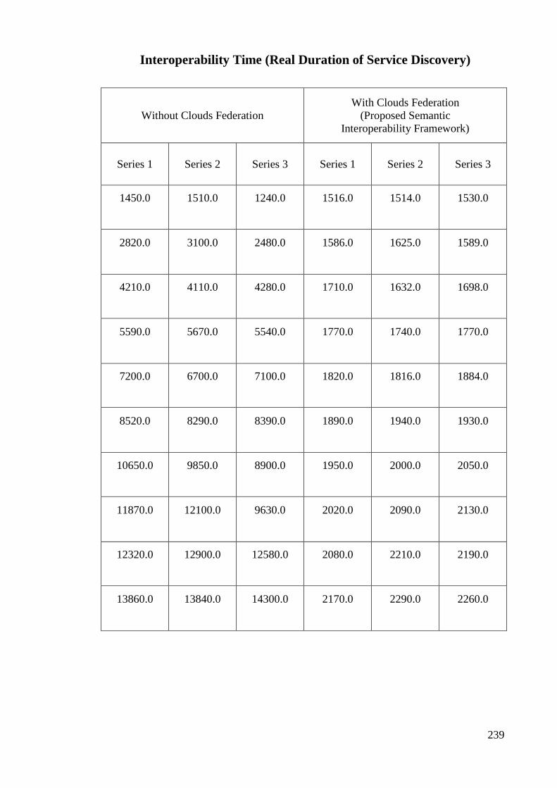
239
Interoperability Time (Real Duration of Service Discovery)
Without Clouds Federation
With Clouds Federation
(Proposed Semantic
Interoperability Framework)
Series 1 Series 2 Series 3 Series 1 Series 2 Series 3
1450.0 1510.0 1240.0 1516.0 1514.0 1530.0
2820.0 3100.0 2480.0 1586.0 1625.0 1589.0
4210.0 4110.0 4280.0 1710.0 1632.0 1698.0
5590.0 5670.0 5540.0 1770.0 1740.0 1770.0
7200.0 6700.0 7100.0 1820.0 1816.0 1884.0
8520.0 8290.0 8390.0 1890.0 1940.0 1930.0
10650.0 9850.0 8900.0 1950.0 2000.0 2050.0
11870.0 12100.0 9630.0 2020.0 2090.0 2130.0
12320.0 12900.0 12580.0 2080.0 2210.0 2190.0
13860.0 13840.0 14300.0 2170.0 2290.0 2260.0

240
Interoperability Quality (Success Rate)
Without Clouds Federation
With Clouds Federation
(Proposed Semantic
Interoperability Framework)
Series 1 Series 2 Series 3 Series 1 Series 2 Series 3
42.0 43.0 35.0 47.0 48.0 49.0
55.0 63.0 62.0 89.0 86.0 89.0
62.0 71.0 68.0 123.0 129.0 120.0
61.0 67.0 52.0 155.0 159.0 157.0
63.0 57.0 45.0 192.0 190.0 197.0
47.0 57.0 55.0 235.0 229.0 229.0
50.0 59.0 56.0 260.0 272.0 275.0
56.0 66.0 40.0 307.0 305.0 309.0
41.0 48.0 61.0 346.0 345.0 341.0
34.0 44.0 60.0 375.0 388.0 383.0

241
Interoperability Cost (Number of Service Request and Response)
Without Clouds Federation
With Clouds Federation
(Proposed Semantic
Interoperability Framework)
Series 1 Series 2 Series 3 Series 1 Series 2 Series 3
2.0 2.0 2.0 2.0 2.0 2.0
9.0 6.0 9.0 2.0 2.0 2.0
20.0 19.0 15.0 2.0 2.0 2.0
29.0 20.0 26.0 2.0 2.0 2.0
39.0 38.0 37.0 2.0 2.0 2.0
45.0 49.0 50.0 2.0 2.0 2.0
56.0 60.0 58.0 2.0 2.0 2.0
69.0 69.0 66.0 2.0 2.0 2.0
76.0 78.0 80.0 2.0 2.0 2.0
86.0 89.0 89.0 2.0 2.0 2.0
99.0 100.0 95.0 2.0 2.0 2.0
107.0 109.0 108.0 2.0 2.0 2.0

242
116.0 120.0 118.0 2.0 2.0 2.0
129.0 129.0 126.0 2.0 2.0 2.0
135.0 139.0 140.0 2.0 2.0 2.0
145.0 150.0 149.0 2.0 2.0 2.0
157.0 160.0 157.0 2.0 2.0 2.0
168.0 167.0 169.0 2.0 2.0 2.0
179.0 177.0 178.0 2.0 2.0 2.0
189.0 188.0 187.0 2.0 2.0 2.0
197.0 198.0 199.0 2.0 2.0 2.0

243
Conformity
Without Clouds Federation
With Clouds Federation
(Proposed Semantic
Interoperability Framework)
Series 1 Series 2 Series 3 Series 1 Series 2 Series 3
7.0 4.0 4.0 54.0 50.0 52.0
40.0 49.0 43.0 90.0 88.0 83.0
21.0 25.0 26.0 95.0 102.0 103.0
32.0 24.0 28.0 149.0 146.0 149.0
80.0 81.0 73.0 175.0 177.0 170.0
49.0 51.0 59.0 213.0 217.0 221.0
144.0 135.0 141.0 245.0 235.0 240.0
98.0 105.0 94.0 300.0 308.0 310.0
99.0 105.0 111.0 326.0 320.0 329.0
157.0 149.0 156.0 415.0 414.0 410.0