a review of the present situation and future developments of micro-batteries for wireless autonomous...
TRANSCRIPT

REVIEW PAPER
A review of the present situation and futuredevelopments of micro-batteries for wirelessautonomous sensor systemsJ. F. M. Oudenhoven*,†, R. J. M. Vullers and R. van Schaijk
Holst Centre/IMEC, High Tech Campus 31, 5656 AE Eindhoven, The Netherlands
SUMMARY
Wireless sensor nodes (WSNs) are expected to play an increasing role in multiple application areas. These application areasvary from networks around the human body, sensors in smart tires, sensor networks that can control the safety and comfortlevels throughout smart buildings, sensors that monitor the necessity for maintenance and sensors that track the conditionsof food throughout the distribution chain. These wireless sensors need energy, which can be supplied by a battery or anenergy harvester. However, even when an energy harvester is applied, energy storage is required to serve as energy buffer.In this review, the requirements that different types of wireless sensor networks impose on these batteries are explored, andseveral suitable types of batteries are reviewed. Moreover, the trends in battery development are described, and the futureimprovements are predicted. Finally, the possibilities are discussed to select a battery with properties that are matched to therequirements of the sensor nodes. Copyright © 2012 John Wiley & Sons, Ltd.
KEY WORDS
wireless autonomous sensor system; battery; micro-battery; future trends
Correspondence
*J. F. M. Oudenhoven, Holst Centre/IMEC, High Tech Campus 31, 5656 AE Eindhoven, The Netherlands.†E-mail: [email protected]
Received 19 March 2012; Revised 27 June 2012; Accepted 6 July 2012
1. INTRODUCTION
Wireless sensor nodes (WSNs) are employed today in manydifferent application areas, ranging from health and lifestyle,automotive, smart building, predictive maintenance (e.g. ofmachines and infrastructure), smart packaging to active radiofrequency identification tags. However, currently thesedevices have limited operational lifetime as they requiresignificant operating power.
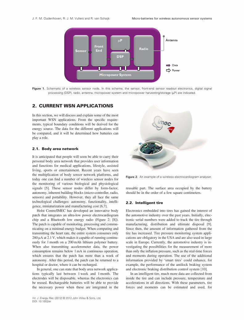
In Figure 1, the basic building blocks of a wireless sensornode are depicted. The analog data from the sensor isconverted to digital values, processed by a digital signalprocessor, and the result is sent to the outside world by theradio. The power is delivered by a micropower system,which either consists of a battery or an energy harvester.
At this moment, most examples of WSN are singlepoint-measurements, where the sensor node communicateswith a base station. In the future, wireless mesh networkswill be applied, which increases the need for autonomoussolutions. Many efforts are ongoing to decrease the powerconsumption of the sensor nodes. It is expected that manyapplications will be able to reduce their power consumptionto below 100mW [1]. In 2008, we estimated the battery
lifetime in case of a 100mW average power and 1 cm3
volume. A battery can only deliver the required energy foraround 2months [2]. Clearly, for these small devices, energyharvesting is the only alternative. This could limit the use ofWSNs because of the need for large batteries.
It has been reported that the energy density increase ofbatteries has been limited to a factor of two to three perdecade [3]. However, many recent publications haveclaimed improvements in materials or new device conceptsthat may lead to an accelerated energy density increase.This will affect the application window for wireless sensornodes. It is the subject of this paper to review the newimprovements and to predict how this will influence theautonomy of a 1 cm3 size WSN. As has been pointed outby others [4], care has to be taken to interpret some of theclaims stated in research papers, as many of the propertiesreported are only valid for subparts and not for completepackaged battery systems. We will, on the other hand, onlyfocus on complete batteries and first discuss the requirementsfor batteries for the WSN applications, and then we willpresent the current status of battery technology. Finally, theprogress in the field will be discussed, and from estimates,the future limits of battery-operated WSN.
INTERNATIONAL JOURNAL OF ENERGY RESEARCHInt. J. Energy Res. (2012)
Published online in Wiley Online Library (wileyonlinelibrary.com). DOI: 10.1002/er.2949
Copyright © 2012 John Wiley & Sons, Ltd.
2. CURRENT WSN APPLICATIONS
In this section, we will discuss and explain some of the mostimportant WSN applications. From the specific require-ments, typical boundary conditions will be derived for theenergy source. The data for the different applications willbe compared, and it will be determined how batteries canplay a role.
2.1. Body area network
It is anticipated that people will soon be able to carry theirpersonal body area network that provides user informationand functions for medical applications, lifestyle, assistedliving, sports or entertainment. Recent years have seenthe multiplication of body sensor network platforms, andtoday one can find a number of wireless sensor nodes forthe monitoring of various biological and physiologicalsignals [5]. These sensor nodes differ by form-factor,autonomy, inherent building blocks (micro-controller, radio,sensors) and portability. However, they all face the sametechnological challenges: autonomy, functionality, intelli-gence, miniaturization and manufacturing cost [6,7].
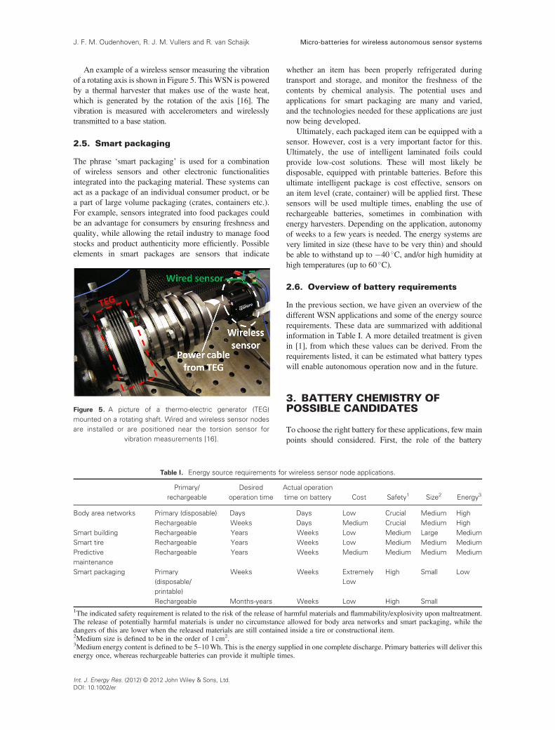
Holst Centre/IMEC has developed an innovative bodypatch that integrates an ultra-low power electrocardiogramchip and a Bluetooth low energy radio (Figure 2; [8]).The patch is capable of monitoring, processing and commu-nicating on a minimal energy budget. When computing andtransmitting the heart rate, the entire system consumes only280mA at 2.1V, which makes it capable of running continu-ously for 1month on a 200mAh lithium polymer battery.When also transmitting accelerometer data, the powerconsumption remains below 1mA in continuous operation,which ensures that the patch has more than a week ofautonomy. After this period, the patch can be returned to ahospital or doctor, where it can be recharged.
In general, one can state that body area network applica-tions typically last between 1week and 1month. Theelectrodes will be disposable, whereas the electronics canbe reused. Rechargeable batteries will be able to providethe necessary power when these are integrated in the
reusable part. The surface area occupied by the batteryshould be in the order of a few square centimeters.
2.2. Intelligent tire
Electronics embedded into tires has gained the interest ofthe automotive industry over the past years. Initially, elec-tronic serial numbers were added to track the tire throughmanufacturing, distribution and ultimate disposal [9].Since then, the amount of information gathered from thetire has increased. Tire pressure monitoring system appli-cations are obligatory in the USA and are also used in largescale in Europe. Currently, the automotive industry is in-vestigating the possibilities for the measurement of morethan only the inflation pressure, such as the real-time forcesand moments during operation. The use of the additionalinformation provided by ‘smart tires’ could enhance, forexample, the performance of the antilock braking systemand electronic braking distribution control system [10].
In an intelligent tire, much more data are collected frominside the tire and can include pressure, temperature andaccelerations in all directions. With these parameters, tireforces and moments can be estimated and used, for
Figure 1. Schematic of a wireless sensor node. In this scheme, the sensor, front-end sensor readout electronics, digital signalprocessing (DSP), radio, antenna, micropower system and micropower harvesting/storage (mP) are indicated.
Figure 2. An example of a wireless electrocardiogram analyser.
Micro-batteries for wireless autonomous sensor systemsJ. F. M. Oudenhoven, R. J. M. Vullers and R. van Schaijk
Int. J. Energy Res. (2012) © 2012 John Wiley & Sons, Ltd.DOI: 10.1002/er

example, for estimating the status of the road (rain, ice etc.).The data are sent to a vehicle computer where it is used asinput for safety systems. Because it is essential that thesesystems are incorporated into the liner of the tire, the systemshave to be small, have a low weight and should be able towithstand large external accelerations (hundreds of g) andlarge temperature variations (�40 to 125 �C). Whereas tirepressure monitoring system can be powered by a primarybattery, intelligent tires need much more energy, and onlythe combination of an energy harvester with a rechargeablebattery will be sufficient. Vibration harvesting is then thelogical choice. In [11] (Figure 3), such a system is explainedin more detail. This system is based on a piezoelectricharvester. Similarly, an electrostatic-based harvester can beused in combination with shocks [12,13].
2.3. Smart building
Building automation has attracted substantial attentionfrom both research and industry in recent years [14]. Thegoals are to increase occupant comfort, improve buildingsecurity and maximize energy efficiency. In order toachieve these goals, intelligent and cooperative sensornetworks are employed in the system. Thus, a buildingautomation system is a combination of sensors, actuatorsand communication. Information on human activity andenvironmental parameters, for example, temperature,humidity, CO2 levels and light intensity, is to be detectedand collected by a sensor node in one place, or a fewdistributed sensor nodes in different places. The signal sent
out by these nodes is collected wirelessly at a central pointfor further processing. An example of a possible setup isshown in Figure 4. In a typical building, with 1–10 sensornodes per room, one can expect thousands of sensors to beinstalled. For a building under construction, adding extrapower and communication cables to sensors is almosttrivial. However, after some period when new occupantsenter, the layout of the building might change. Also, majorrefurbishments are needed about every 10 years to prolongthe lifetime of an office building. In these two cases, theaddition of extra power cables is labor intensive and thusbecoming very expensive. The required sensors should beable to operate any time between 1 and 30 years, whereasthe volume is limited to a few cubic centimeters. For mostapplications, batteries will run down during the requiredlifetime of the sensor. If battery replacement is not anoption, energy harvesting (e.g., by capturing the lightinside the office or by RF energy transfer) in combinationwith a rechargeable battery will be the only solution.
2.4. Predictive maintenance
To prevent machine breakdowns and disruptions of normaloperations, machines and vehicles need to be taken out oftheir operation environment regularly to be inspected, some-times piece by piece. Real-time monitoring of critical para-meters allows scheduling maintenance activities exactlywhen and where they are needed, based on data from wiredor wireless sensors [15]. This is called predictive mainte-nance. Wireless sensors for real-time monitoring provideimmediate benefits to end users, including (i) avoidance ofthe costly installation of cables, (ii) easy deployment inotherwise inaccessible locations and (iii) improved datarelevance by enabling measurements on moving parts. Theexact autonomy depends on the machine and application;however, the minimum is 6months, although typically manyyears of operation are required. The volume of the energysource may vary, but usually it is restricted because of sizeor mass restrictions.
Figure 3. An intelligent tire with incorporated sensors, batteryand energy harvester.
Figure 4. An intelligent building layout, with wireless sensornetworks installed to optimize the comfort levels and safety in
the building.
Micro-batteries for wireless autonomous sensor systems J. F. M. Oudenhoven, R. J. M. Vullers and R. van Schaijk
Int. J. Energy Res. (2012) © 2012 John Wiley & Sons, Ltd.DOI: 10.1002/er
An example of a wireless sensor measuring the vibrationof a rotating axis is shown in Figure 5. ThisWSN is poweredby a thermal harvester that makes use of the waste heat,which is generated by the rotation of the axis [16]. Thevibration is measured with accelerometers and wirelesslytransmitted to a base station.
2.5. Smart packaging
The phrase ‘smart packaging’ is used for a combinationof wireless sensors and other electronic functionalitiesintegrated into the packaging material. These systems canact as a package of an individual consumer product, or bea part of large volume packaging (crates, containers etc.).For example, sensors integrated into food packages couldbe an advantage for consumers by ensuring freshness andquality, while allowing the retail industry to manage foodstocks and product authenticity more efficiently. Possibleelements in smart packages are sensors that indicate
whether an item has been properly refrigerated duringtransport and storage, and monitor the freshness of thecontents by chemical analysis. The potential uses andapplications for smart packaging are many and varied,and the technologies needed for these applications are justnow being developed.
Ultimately, each packaged item can be equipped with asensor. However, cost is a very important factor for this.Ultimately, the use of intelligent laminated foils couldprovide low-cost solutions. These will most likely bedisposable, equipped with printable batteries. Before thisultimate intelligent package is cost effective, sensors onan item level (crate, container) will be applied first. Thesesensors will be used multiple times, enabling the use ofrechargeable batteries, sometimes in combination withenergy harvesters. Depending on the application, autonomyof weeks to a few years is needed. The energy systems arevery limited in size (these have to be very thin) and shouldbe able to withstand up to �40 �C, and/or high humidity athigh temperatures (up to 60 �C).
2.6. Overview of battery requirements
In the previous section, we have given an overview of thedifferent WSN applications and some of the energy sourcerequirements. These data are summarized with additionalinformation in Table I. A more detailed treatment is givenin [1], from which these values can be derived. From therequirements listed, it can be estimated what battery typeswill enable autonomous operation now and in the future.
3. BATTERY CHEMISTRY OFPOSSIBLE CANDIDATES
To choose the right battery for these applications, few mainpoints should considered. First, the role of the battery
Figure 5. A picture of a thermo-electric generator (TEG)mounted on a rotating shaft. Wired and wireless sensor nodesare installed or are positioned near the torsion sensor for
vibration measurements [16].
Table I. Energy source requirements for wireless sensor node applications.
Primary/rechargeable
Desiredoperation time
Actual operationtime on battery Cost Safety1 Size2 Energy3
Body area networks Primary (disposable) Days Days Low Crucial Medium HighRechargeable Weeks Days Medium Crucial Medium High
Smart building Rechargeable Years Weeks Low Medium Large MediumSmart tire Rechargeable Years Weeks Low Medium Medium MediumPredictivemaintenance
Rechargeable Years Weeks Medium Medium Medium Medium
Smart packaging Primary(disposable/printable)
Weeks Weeks ExtremelyLow
High Small Low
Rechargeable Months-years Weeks Low High Small1The indicated safety requirement is related to the risk of the release of harmful materials and flammability/explosivity upon maltreatment.The release of potentially harmful materials is under no circumstance allowed for body area networks and smart packaging, while thedangers of this are lower when the released materials are still contained inside a tire or constructional item.2Medium size is defined to be in the order of 1 cm2.3Medium energy content is defined to be 5–10Wh. This is the energy supplied in one complete discharge. Primary batteries will deliver thisenergy once, whereas rechargeable batteries can provide it multiple times.
Micro-batteries for wireless autonomous sensor systemsJ. F. M. Oudenhoven, R. J. M. Vullers and R. van Schaijk
Int. J. Energy Res. (2012) © 2012 John Wiley & Sons, Ltd.DOI: 10.1002/er

needs to be identified: it may serve as a standalone powersupply for the application, or alternatively if an energyharvester is applied, as a temporary storage of energysupplied by this harvester. This first division alreadydetermines whether a secondary (rechargeable) battery isrequired or a primary (single use) battery is sufficient.The next step in choosing the right battery for a specificapplication is to determine the required energy density,maximum self-discharge and application conditions. Theproperties of a battery that determine whether theserequirements can be fulfilled are mainly determined bythe physical properties of the battery and the (electro)chemical mechanism by which the energy is stored. Apartfrom these technical requirements, also financial andenvironmental considerations will influence the choice ofbattery type. In this section, a few of the most commonbattery chemistries are described, and their technical (dis)advantages will be sketched. The general properties ofthese batteries are also summarized in Table II.
3.1. Primary batteries
3.1.1. Zn-MnO2
The combination of metallic zinc and a manganesedioxide electrode is one of the most popular and mostclassic battery chemistries. Basically, two (chemical) typesof these batteries exist: the zinc-carbon cell and thealkaline battery. The chemical difference between thesebatteries lies in the electrolyte: for the zinc-carbon cells,the electrolyte consists of a solution of ammonia chlorideand/or zinc chloride, whereas alkaline cells contain aKOH solution. Although this type of battery is more than100 years old, the chemical processes are still under debate[17]. Moreover, the reaction mechanism may depend onthe discharge currents and amount of electrolyte. The mainmechanism is, however, based on the oxidation of zinc andthe reduction of MnO2.
The voltage window of these batteries is between 1.5and 0.9V, although the slope of the discharge profile isdifferent for zinc-carbon and alkaline cells: equivalentZnC batteries have a much steeper discharge profile thanalkaline batteries. The capacity of these batteries is alsodifferent: the energy density of a typical AA (approxi-mately 8 cm3) zinc-carbon cell is 100mWhcm�3 [18],whereas a commercial alkaline cell reaches at present upto 400mWh cm�3 [19].
Positive aspects of these two types of batteries are thatthe technique is proven and that the batteries are relativelylow cost. The ZnC battery has a poor performance at lowtemperatures and a relatively high self-discharge rate. Thealkaline cell performs better on all these aspects, but issomewhat more expensive and contains a caustic alkalineelectrolyte, which may when leaking impose damage onthe equipment it is installed in.
3.1.2. Lithium primary batteriesLithium primary batteries use a different type of
chemistry. The anode typically consists of metallic lithium,and for the cathode, several materials are available. Mostfrequently used is MnO2, which commonly delivers atotal cell voltage of around 3V. This type of batteryhas an overall reaction based on the oxidation oflithium and reduction of manganese. The most commonform factor of this battery is a button cell, cylindrical cellsand cells with a size equivalent to two AA batteries. Thistype of battery has a typical energy density of 650mWhcm�3 [20].
A second type of lithium battery is based on the sameanode, but has a FeS2 cathode. This battery has a practicalvoltage of 1.5V and is therefore compatible with alkalineand zinc-carbon cells. It is usually produced in AAgeometry and has an energy density of approximately550mWhcm�3 but is capable of delivering much highercurrents and has a much flatter voltage profile upondischarging. Moreover, it performs well at low temperaturesand has a significantly lighter weight than alkaline cells [21].
3.1.3. Zn-air batteriesZn-air batteries are a class of batteries that employ
metallic zinc particles as its anode and an aqueous liquidelectrolyte. For this type of battery, oxygen from thesurrounding air is reduced at a catalyst inside the battery.This has the main advantage that one of the batteryelectrode materials is not inside the battery and that thebattery can therefore have an exceptionally high volumetricand gravimetric energy density. With a voltage of 1.4V, thisbattery is commercially available as button cells with anenergy density of around 1500mWhcm�3 [22]. The disad-vantage of this type of battery is that it needs an open contactwith the surrounding air. Therefore, it can only be applied indevices that allow such direct air contact. This introducesalso the intrinsic disadvantage of this battery: the air contact
Table II. Properties of various typical batteries.
Primary/rechargeable Operation time (100 mW)1 Cost Safety Size Energy density
Printed Zn/MnO2 Primary Weeks–months Low Medium Thin (<1mm) MediumLithium button Primary Months Medium Medium Medium MediumZn-air button Primary Weeks–months High Medium Small HighLi-ion prismatic Rechargeable Months–years Medium Medium Medium–large Medium–highPlanar thin-film Rechargeable Hours–days High High Thin (<1mm) LowFuture 3D solid-state Rechargeable Weeks High High Thin (<1mm) High1The mentioned operation time for rechargeable batteries is defined as the maximum time that a fully charged battery can deliver 100mW ofpower without recharging.
Micro-batteries for wireless autonomous sensor systems J. F. M. Oudenhoven, R. J. M. Vullers and R. van Schaijk
Int. J. Energy Res. (2012) © 2012 John Wiley & Sons, Ltd.DOI: 10.1002/er

will, depending on the air humidity, result in the evaporationof water from the battery electrolyte or a water gain, whichwill both negatively influence the battery performance.This effect is commonly reduced with the application of ahydrophobic membrane.
Other disadvantages of this type of batteries are that thecatalyst that is required for the reduction of oxygen usuallyconsists of expensive noble metals and that the battery isunable to deliver high peak currents. This type of battery istherefore commonly used in applications where only lowcurrents are required from a battery with a small volume.The most common application at present for zinc–airbatteries is therefore in hearing aids.
3.2. Rechargeable batteries
Several candidate chemistries for rechargeable batterieswill be discussed in this section. Only battery types thatare considered feasible for wireless sensor networks willbe discussed here. Other rechargeable battery systemsthat are popular but have a too-low energy density (e.g.,lead–acid batteries) or which are for most applicationsphased out due to legislation (e.g., NiCd batteries [23])are not discussed.
3.2.1. Nickel metal hydride batteriesNickel metal hydride batteries (usually abbreviated as
NiMH batteries) use for their energy storage mechanismthe valence states of nickel at the positive electrode, whereasthe oxidation/reduction of hydrogen (in the form of metalhydrides) serves as the negative electrode reaction. Inthe charged state, the positive electrode consists of nickeloxyhydroxide and the anode of a metal hydride. Duringdischarge, nickel oxyhydroxide is reduced to nickelhydroxide, obtaining a proton from water in the electrolyte.For this, a hydroxide anion is formed in the electrolyte thatwill subsequently recombine with a proton from the metalhydride, forming the metal and water. This reaction systemis reversed during charging.
Using this electrochemical process, an effective cellvoltage around 1.2V is obtained. This voltage makesNiMH batteries generally interchangeable with alkalinebatteries, and these batteries are frequently used to replacethese in various consumer applications. Moreover, NiMHbatteries are, when properly designed, intrinsically safe.When this type of battery is overcharged, oxygen is formedat the nickel-based electrode, which will react at the metalhydride electrode to form water. No pressure build-up willoccur, and it is even often advised to continue to apply alow current to a fully charged battery to keep it fullycharged (trickle charging). The main disadvantage ofNiMH batteries is that these have a relatively narrowtemperature window (0–45 �C) and that the self-dischargeof this type of battery is relatively high [24]. The volumetricenergy density of commercial AA-sized NiMH batteriesvaries between 250 and 380mWhcm�3 [25].
3.2.2. Li-ion batteriesA second well-known type of rechargeable batteries is
the lithium-ion (Li-ion) battery. This battery is oftenapplied in mobile equipment (e.g., cell phones, camerasor laptop computers) because of its high gravimetric andvolumetric energy density. The basic principle of a Li-ionbattery is that during charging and discharging, lithiumions are shuttled between the two electrodes. The positiveelectrode typically consists of a lithium metal oxide,whereas the negative electrode employs a material thatcan store lithium in a neutral form. Typical examples ofthese are LiCoO2 for the positive and graphite for thenegative electrode. When this type of battery is charged,lithium ions are extracted from the metal oxide, transportedthrough the electrolyte and stored in graphite. When thebattery is discharged, this process is reversed.
Because there is a large variety of electrode materialsavailable for Li-ion batteries, there is also a large spreadin battery voltage. Typically, commercial Li-ion batteriesare available with a discharge voltage between 3.0 and3.9V. The advantages of Li-ion batteries over NiMHbatteries are that these generally have a higher energydensity (for large-scale cells typically between 300 and500mWh cm�3) [26], lower self-discharge rate and largertemperature window (�20 to 60 �C). The disadvantage ofthis type of battery is that these are not compatible with‘normal’ AA batteries because of their deviating voltageand that overcharging and overdischarging will damagethe battery and possibly even cause a thermal runaway.Therefore, a dedicated protective electric circuit is alwaysrequired to keep the battery within a safe voltage range.
3.2.3. New developmentsAlthough a large part of the ongoing research in the
field of energy storage is focusing on improving theexisting types of batteries, for example, by developingnew electrode materials, optimizing structures and optimi-zation of use scenarios, also new types of rechargeablebatteries are being developed that have different underlyingmechanisms. These batteries are not yet commerciallyavailable but can form the basis of future batteries.
For primary batteries, it is well established that thehighest energy density can be obtained with an airelectrode. From the batteries described earlier, the Zn-airbattery has the highest energy density. Analogous to this,also lithium-air batteries are being developed. Theseproposed batteries have a working mechanism that is anintermediate between Li-ion and Zn-air batteries. Theycontain a negative electrode that consists of pure metalliclithium, which will dissolve in the electrolyte in the formof Li+ during battery discharge. At the air electrode ofthe battery, Li+ ions will react with oxygen to form Li2Oor Li2O2 [27,28]. The maximum theoretical energydensity, excluding the volume of passive components suchas the current collectors, membrane and packaging, forthese type of batteries, is 2800mWhcm�3 [29]. Thepractical energy density will, however, be much lowerbecause of the volume of the passive materials and
Micro-batteries for wireless autonomous sensor systemsJ. F. M. Oudenhoven, R. J. M. Vullers and R. van Schaijk
Int. J. Energy Res. (2012) © 2012 John Wiley & Sons, Ltd.DOI: 10.1002/er

non-optimal use of the active materials. It is expected thatthe practical energy density will be less than half of thetheoretical value. For example, the theoretical maximalenergy density of a LiCoO2/graphite Li-ion battery isapproximately 1400mWhcm�3 (based on a capacity of700mAhcm�3 for LiCoO2 and 830mAhcm�3 for graphite,with a negligibly small volume occupied by the electrolyte,current collector and packaging). In reality, however, com-mercial batteries that were mentioned in the previous sectionreach only approximately one third of this value. Therefore,it is expected that also for Li-air batteries, the realistic energydensity will reach at most 1400mWhcm�3, which isstill much higher than other available rechargeable batterysystems. There are, however, a few strong disadvantages ofLi-air batteries. First, of course, an access to oxygen from airshould be available, which limits the fields of application forthis type of batteries. Second, the power density that thesebatteries can deliver is limited. A third point of considerationis that, until now, the efficiency of these batteries has shownto be very low. The voltage required for charging this batteryis much higher than the discharging voltage. Therefore,the energetic cycling efficiency of these batteries is relativelypoor [30].
4. THE BATTERY FORM FACTORAND PRODUCTION METHOD
For many mobile devices, the form factor of the battery isdominant for the shape and size of a device. This is mostclearly the case for classical batteries, which have theshape of a metal cylinder or for small dimensions a coinor button. In a cylindrical shape, basically two types ofbatteries are produced. The first type consists of a metalcan that is filled with two bulk electrode materialsseparated by a thin separator film. Usually, the center ofthis battery is formed by a conductive pin or rod, which
ensures good electrical conductivity from the electrodematerial to the top contact. The other contact is provided bythe metal container of the battery. This type of cell iscommonly denominated as the bobbin-type cell, which is acommon geometry for primary batteries such as thealkaline battery. A second type of cylindrical cell is thespirally wound cell. This cell contains a roll of thinelectrode sheets, combined with a separator and an insulatingfoil. This shape is commonly used for high current applica-tions and can be found in primary and secondary lithiumbatteries and other rechargeable battery types. Button orcoin cells are usually of a bulk-material type (Figure 6). Thearea of the contact pads is in this case relatively large and ametal pin, like in a bobbin cell, is in this case not required.
The advantage of these cylindrical or disk-shapedmetallic cells is that they are robust and easily produced.However, these form factors are not always convenient toincorporate into the design of electronic equipment,certainly when miniaturization is required.
With the miniaturization of electronics in mind, thedesign of batteries has changed over the past decades,and different types of prismatic or other thin batteries havebeen designed. In most well-know prismatic cells, thesame thin electrodes are applied as in a spirally wound cell,but now these foils are not wound and inserted in a metalcan but folded and laminated within a cover of plasticizedaluminum foil (Figure 6). This has the advantage that itoffers more freedom in shape, size and design, and thelayout of the cell can be more easily adapted to the designof the electronics. One step further in miniaturization isthat no laminated sheets are used but thin films (Figure 6).These films can be printed or deposited by depositiontechniques such as sol–gel, electrodeposition, physicaland chemical vapor deposition or atomic layer depositiontechnology. Frequently, these thin electrode films arecombined with a separator sheet that is soaked with aliquid electrolyte. Several of these types of printed batteriesare presently marketed by battery manufacturers [31].
Figure 6. Schematic layout of three different micro-batteries: button cells (left), pouch cells (center) and thin film batteries (right). Onthe top image, the full battery is shown, whereas an opened battery is displayed at the bottom to indicate the electrode configuration.
Micro-batteries for wireless autonomous sensor systems J. F. M. Oudenhoven, R. J. M. Vullers and R. van Schaijk
Int. J. Energy Res. (2012) © 2012 John Wiley & Sons, Ltd.DOI: 10.1002/er
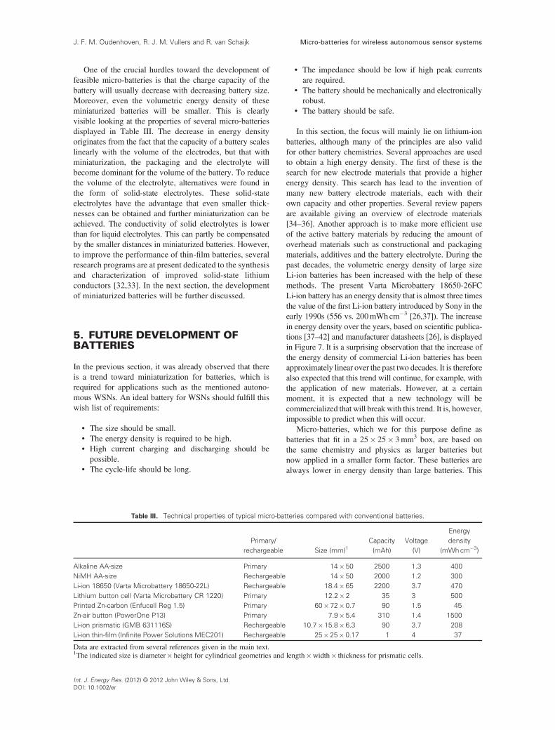
One of the crucial hurdles toward the development offeasible micro-batteries is that the charge capacity of thebattery will usually decrease with decreasing battery size.Moreover, even the volumetric energy density of theseminiaturized batteries will be smaller. This is clearlyvisible looking at the properties of several micro-batteriesdisplayed in Table III. The decrease in energy densityoriginates from the fact that the capacity of a battery scaleslinearly with the volume of the electrodes, but that withminiaturization, the packaging and the electrolyte willbecome dominant for the volume of the battery. To reducethe volume of the electrolyte, alternatives were found inthe form of solid-state electrolytes. These solid-stateelectrolytes have the advantage that even smaller thick-nesses can be obtained and further miniaturization can beachieved. The conductivity of solid electrolytes is lowerthan for liquid electrolytes. This can partly be compensatedby the smaller distances in miniaturized batteries. However,to improve the performance of thin-film batteries, severalresearch programs are at present dedicated to the synthesisand characterization of improved solid-state lithiumconductors [32,33]. In the next section, the developmentof miniaturized batteries will be further discussed.
5. FUTURE DEVELOPMENT OFBATTERIES
In the previous section, it was already observed that thereis a trend toward miniaturization for batteries, which isrequired for applications such as the mentioned autono-mous WSNs. An ideal battery for WSNs should fulfill thiswish list of requirements:
• The size should be small.• The energy density is required to be high.• High current charging and discharging should bepossible.
• The cycle-life should be long.
• The impedance should be low if high peak currentsare required.
• The battery should be mechanically and electronicallyrobust.
• The battery should be safe.
In this section, the focus will mainly lie on lithium-ionbatteries, although many of the principles are also validfor other battery chemistries. Several approaches are usedto obtain a high energy density. The first of these is thesearch for new electrode materials that provide a higherenergy density. This search has lead to the invention ofmany new battery electrode materials, each with theirown capacity and other properties. Several review papersare available giving an overview of electrode materials[34–36]. Another approach is to make more efficient useof the active battery materials by reducing the amount ofoverhead materials such as constructional and packagingmaterials, additives and the battery electrolyte. During thepast decades, the volumetric energy density of large sizeLi-ion batteries has been increased with the help of thesemethods. The present Varta Microbattery 18650-26FCLi-ion battery has an energy density that is almost three timesthe value of the first Li-ion battery introduced by Sony in theearly 1990s (556 vs. 200mWhcm�3 [26,37]). The increasein energy density over the years, based on scientific publica-tions [37–42] and manufacturer datasheets [26], is displayedin Figure 7. It is a surprising observation that the increase ofthe energy density of commercial Li-ion batteries has beenapproximately linear over the past two decades. It is thereforealso expected that this trend will continue, for example, withthe application of new materials. However, at a certainmoment, it is expected that a new technology will becommercialized that will break with this trend. It is, however,impossible to predict when this will occur.
Micro-batteries, which we for this purpose define asbatteries that fit in a 25� 25� 3mm3 box, are based onthe same chemistry and physics as larger batteries butnow applied in a smaller form factor. These batteries arealways lower in energy density than large batteries. This
Table III. Technical properties of typical micro-batteries compared with conventional batteries.
Primary/rechargeable Size (mm)1
Capacity(mAh)
Voltage(V)
Energydensity
(mWhcm�3)
Alkaline AA-size Primary 14� 50 2500 1.3 400NiMH AA-size Rechargeable 14� 50 2000 1.2 300Li-ion 18650 (Varta Microbattery 18650-22L) Rechargeable 18.4� 65 2200 3.7 470Lithium button cell (Varta Microbattery CR 1220) Primary 12.2� 2 35 3 500Printed Zn-carbon (Enfucell Reg 1.5) Primary 60� 72� 0.7 90 1.5 45Zn-air button (PowerOne P13) Primary 7.9� 5.4 310 1.4 1500Li-ion prismatic (GMB 631116S) Rechargeable 10.7� 15.8� 6.3 90 3.7 208Li-ion thin-film (Infinite Power Solutions MEC201) Rechargeable 25� 25� 0.17 1 4 37
Data are extracted from several references given in the main text.1The indicated size is diameter� height for cylindrical geometries and length�width� thickness for prismatic cells.
Micro-batteries for wireless autonomous sensor systemsJ. F. M. Oudenhoven, R. J. M. Vullers and R. van Schaijk
Int. J. Energy Res. (2012) © 2012 John Wiley & Sons, Ltd.DOI: 10.1002/er

is mainly due to the fact that the packaging materialscannot be scaled down beyond a certain minimum and willtherefore become more dominant for the energy densitywhen the battery is scaled down further. Miniaturizedbutton cells have, for example, a relatively thick metalcan that will occupy a significant part of the volume. Forbatteries consisting of a sealed package, something similaris observed: the sealing edges will consume a relatively largevolume. It is therefore not surprising that the properties listedfor micro-battery types from past and present show an energydensity that is consistently less than 50% of the value formacro-batteries [26,43]. Some basic technical properties ofthese batteries are displayed in Table III. Also these batterieshave improved over time, but because these are based on thesame principles as large-scale batteries, their developmenthas also gone hand in hand, as may be observed in Figure 7.
One would expect that this effect will be even strongerfor all solid-state thin-film micro-batteries, which areminiaturized further using a very thin layer of solid-stateelectrolyte. These batteries have a total thickness that isusually less than a millimeter. The energy density of thefirst introduced micro-batteries [44] and the batteries thatare available at present [45] is indeed much lower thanfor other micro-batteries (Table III). However, with thesmart use of thin-film techniques, it is possible to reducethe thickness of the substrate and electrolyte. Whenrelatively thick films are used for the electrodes, and a thinelectrolyte and thin packaging materials are applied, itshould be possible to optimize the present-day technologyto produce a thin-film battery that has a much higherenergy density, which may at a certain moment competewith classic micro-batteries in energy density. The pastand present energy densities and the estimated futuredevelopments for the next 20 years are given in Figure 7.Of course, future predictions based on the present situation
are always limited to developments in current technology.These predictions do not take into account any new,disruptive, technology and have a large degree of uncertaintythat is influenced by research priorities and the commercialsituation. When only looking at technology, it is expectedthat with only an increase in electrode thickness (by advancesin production techniques), while keeping the electrolyte andpackaging at their current thin level, the energy density ofthin-film batteries can be increased by a factor five in thecoming 10 years. When also different electrode materialsare applied and thinner packaging and electrolytes can beused, another factor two increase can be expected 20 yearsfrom now.
The energy density of thin-film micro-batteries can infuture even be increased further by making use of thepassive materials in a smart way. The amount of packagingcan, for example, be reduced by sharing the packagingwith a sensor, radio or signal processing unit and so on.An approach that goes one step further, which wasproposed by Notten et al. [36,46], is to use the volume ofthe substrate to increase the available volume for thebattery. This can be achieved by anisotropic etching of Sito increase the active surface area of a silicon substrateand increase the possible electrode volume withoutincreasing the total volume of the thin-film battery.Although no 3D thin-film batteries are available yet, itwas estimated by Notten et al. that the concept wouldresult in batteries with an energy density of 5mWh cm�2
footprint area when a 1-mm-thick LiCoO2 cathode is used[46]. Considering that a Si wafer plus battery is approxi-mately 700-mm thick, this would result in a battery withan energy density of 71mWh cm�3. Because this batteryis still in development, this estimate is used as a predictionfor 3D thin-film batteries in 2015 in Figure 7. This is, ofcourse, a rather modest estimate, because the used waferhas a thickness up to 700mm, and the 5-mm-wide trenchesused to create the 3D geometry have a depth of only135mm [47]. An optimization step could, for example, bemade by thinning down the wafer to 200mm. Anotherimprovement could be made by increasing the LiCoO2 filmthicknesses to 1.75mm, which will together with theelectrolyte and anode fill the trenches completely. Thesetwo improvements would result in a factor six increase inenergy density, the predicted value for 2025 in Figure 7.If the 3D geometry is further optimized and if high-energydensity electrode materials are applied, a further factor twoincrease is expected for the subsequent 10 years.
These future predictions are based only on technologicaladvances. Of course, for example, economic developments,changes in regulations and commercial aspects will have amajor influence on the battery future. Moreover, these plotsonly show technological advances for a maximized energydensity. Optimization of other aspects, for example, thecharging time, the maximum current that can be deliveredby the battery and so on, might have a negative influenceon the energy density.
The use of nanotechnology can also improve batteryperformance. When only nanometer-dimension electrodes
Figure 7. The development of Li-ion batteries over the years.The past and present data points are based on manufacturerdatasheets and scientific literature [26,37–45]. The future trendsare based on the extrapolation of observed past trends andestimates of chemical and material science developments in
the future.
Micro-batteries for wireless autonomous sensor systems J. F. M. Oudenhoven, R. J. M. Vullers and R. van Schaijk
Int. J. Energy Res. (2012) © 2012 John Wiley & Sons, Ltd.DOI: 10.1002/er

are used, materials that were until now not used becauseof a too low conductivity will become available that mayresult in a very high energy density. One of these materialsis, for example, sulfur. When this material is combinedwith a carbon nanostructure that ensures a good electronicand ionic conductivity, it can be applied successfully as anelectrode [48].
The previous paragraphs mainly focus on the battery asis, a conventional battery made with new technologies ornew materials, but still as a separate battery. Furtherimprovement could, for example, come from the integrationof batteries with devices, not a separate battery and harvester,but a combined system: a harvester that can also store itsenergy. For example, generic micromachining techniquesthat are used to produce micro-batteries can be used to makepiezoelectric energy harvesters [11] and fuel cells [49,50].One could, for example, think of an enzymatic biofuel cellor photovoltaic cell that is combined with an integratedbattery into a single building block [36].
6. DISCUSSION
In the previous sections, several WSN applications werereviewed and various battery chemistries and constructionmethods were given. Moreover, the expected future develop-ment of especially thin-film batteries was sketched. This typeof information is required to select the best battery for eachapplication. The requirements for the power supply of thementioned WSN applications are summarized in Table Iand the properties of several typical batteries are givenin Table II.
From these tables, it becomes immediately clear thatone solution that fits all approach is impossible: differentapplications have different requirements, and not allbatteries fulfill the whole range of requirements. Whatmay be concluded from these tables is that there is a cleardistinction in the time scales of the applications. Forrelatively short time-scale applications, such as smartpackaging or body area networks, a standalone battery canbe used to deliver a sufficient amount of energy. Dependingon the reusability of the application, a rechargeable orprimary battery may be applied. For long-time applications,for which power should be delivered for multiple years,micro-batteries will not suffice. For these applications, eitherlarger batteries will need to be applied or a rechargeablebattery in combination with an energy harvester. It is,however, expected that in future the performance of severaltypes of batteries will be improved, and therefore the applica-bility of batteries will increase. Moreover, the developmentof low power electronics will further increase the maximumoperation time of a device–battery combination.
7. CONCLUSIONS
At present, most WSNs rely on batteries as their energysource. Currently applied battery technology is, however,
bulky and determines to a large extent the volume of thesensor nodes. Several possibilities are introduced to minia-turize these batteries and to obtain more freedom forthe design of sensor nodes. However, these miniaturizedbatteries will not always suffice as the only energy supplyof the sensor node. It is therefore recommended that foreach application, an evaluation is made to clarify therequirements of the WSN and select what is the mostsuitable power supply.
It is therefore concluded that, although new ultra lowpower electronics will be developed and the technology ofenergy harvesting is continuously improving, it is alwaysnecessary to make an evaluation of what is the best solution:a battery, an energy harvester or a combination thereof.
REFERENCES
1. Vullers R, van Schaijk R, Visser H, Penders J, van HoofC. Energy harvesting for autonomous wireless sensornetworks. IEEE Solid-State Circuits Magazine 2010;2:29–38. doi:10.1109/MSSC.2010.936667.
2. Vullers RJM, van Schaijk R, Doms I, van Hoof C,Mertens R. Micropower energy harvesting. SolidState Electronics 2009; 53:684–693. doi:10.1016/j.sse.2008.12.011.
3. Paradiso JA, Starner T. Energy scavenging for mobileand wireless electronics. IEEE Pervasive Computing2005; 4:18–27. doi:10.1109/MPRV.2005.9.
4. Gogotsi Y, Simon P. True performance metrics inelectrochemical energy storage. Science 2011; 334:917–918. doi:10.1126/science.1213003.
5. Jovanov E, Milenkovic A. Body area networks forubiquitous healthcare applications: opportunities andchallenges. Journal of Medical Systems 2011;35:1245–1254. doi:10.1007/s10916-011-9661-x.
6. Parton E, de Groot H. The way to wireless. EuropeanMedical Device Technology 2010; 1:14–17.
7. Yang GZ. Body Sensor Networks. Springer Verlag:London, 2006.
8. Altini M, Polito S, Penders J, Kim H, van HelleputteN, Kim S, Yazicioglu F. An ECG patch combining acustomized ultra-low-power ECG SoC with Bluetoothlow energy for long term ambulatory monitoring.Proceedings of wireless health, San Diego, 2011.DOI: 10.1145/2077546.2077564.
9. Logan B. In Rubber Technologist’s Handbook, White J,De SK, Naskar K (eds.). Rapra: Smithers, 2009,2, 29–58.
10. Cheli F, Leo E, Melzi S, Sabbioni E. On the impact of‘smart tyres’ on existing ABS/EBD control systems.Vehicle System Dynamics 2010; 48(supp1):255–270.doi:10.1080/00423111003706755.
Micro-batteries for wireless autonomous sensor systemsJ. F. M. Oudenhoven, R. J. M. Vullers and R. van Schaijk
Int. J. Energy Res. (2012) © 2012 John Wiley & Sons, Ltd.DOI: 10.1002/er

11. Elfrink R, Matova S, de Nooijer C, Jambunathan M,Goedbloed M, van de Molengraft J, Pop V, Vullers RJM,Renaud M, van Schaijk R. Shock induced energyharvesting with a MEMS harvester for automotiveapplications. 2011 IEEE International Electron DevicesMeeting (IEDM 2011). ISBN 978-1-4577-0506-9.
12. Sterken T, Fiorini P, Altena G, Van Hoof C, Puers R.Harvesting energy from shocks by a micromachinedelectret generator. Solid-State Sensors, Actuators andMicrosystems Conference 2007 DOI: 10.1109/SENSOR.2007.4300088.
13. Okamoto H, Suzuki T, Mori K, Cao Z, Onuki T,Kuwano H. The advantages and potential of electret-based vibration-driven micro energy harvesters. Interna-tional Journal of Energy Research 2009; 33:1180–1190.doi:10.1002/er.1608.
14. Creatively address rising costs and environmentalconcerns. Available from: http://www.automatedbuild-ings.com/news/dec08/articles/veris/081125042505verve.htm. Accessed on February 29, 2012.
15. Mobley RK. An Introduction to Predictive Maintenance.Butterworth-Heinemann: Woburn, 2002.
16. Wang Z, Bouwens F, Vullers R, Petré F, Devos S.Energy-autonomous wireless vibration sensor forcondition-based maintenance of machinery. Proceedingsof the IEEE Sensors conference 2011, 790–793. DOI:10.1109/ICSENS.2011.6127409.
17. McComsey DW. In Handbook of Batteries, Linden D,ReddyTB (eds.).McGraw-Hill: NewYork, 2002, 8,4–8.5.
18. From datasheets of GP batteries GP15E, GP15S,GP15G. Available from: http://www.gpbatteries.com/html/techinfo/carbon_zinc.asp, http://www.gpbatteries.com/html/techinfo/zinc_chloride.asp. Accessed onFebruary 29, 2012.
19. From datasheets of Energizer UltraPlus (LR6), HighTech (LR6). Available from: http://data.energizer.com/Europe/content/Batteries/alk_west.html. GP batteriesGP15AU, GP15AUP, GP15A. Available from: http://www.gpbatteries.com/html/techinfo/alkaline.asp.PowerOne VARTA Microbattery 4106 (LR6/AA).Available from: http://www.varta-microbattery.com/en/oempages/product_data/batteries_by_technology.php.Accessed on February 29, 2012.
20. Varta Microbattery Type CR AA 6117. Availablefrom: http://www.varta-microbattery.com/en/oempages/product_data/batteries_by_technology.php. Accessed onFebruary 29, 2012.
21. Energizer L91-FR6 datasheet. Available from: http://data.energizer.com/Europe/content/Batteries/Li_ultimate.html.Accessed on February 29, 2012.
22. PowerOne (VARTA Microbattery). Available from:http://www.powerone-batteries.com/index.php?id=23&L=1. Accessed on February 29, 2012.
23. Directive 2006/66/EC of the European Union.24. Linden D, Magnusen D. In Handbook of Batteries,
Linden D, Reddy TB (eds.). McGraw-Hill: New York,2002, 29, 1–29.35.
25. Several Energizer batteries: HR6-2000, HR6-2200,HR6-2400. Available from: http://data.energizer.com/Europe/content/Batteries/accu_rechg.html, and severalGP Batteries: GP170AAHC, GP180AAHC, GP210AAHC, GP230 AAHC, GP250 AAHC, GP270HC.Available from: http://www.gpbatteries.com/html/techinfo/nimh.asp. Accessed on February 29, 2012.
26. Several Li-ion batteries manufactured by GP batteries.Available from: http://www.gpbatteries.com/html/industrial/LithPly.asp. VARTA Microbattery. Avail-able from: http://www.varta-microbattery.com/en/oempages/product_data/batteries_by_technology.php,and GMB power. Available from: http://www.gmbat-tery.com/English/rechargeable-battery.html. Accessedon February 29, 2012.
27. Lee JS, Kim ST, Cao R, Choi NS, Liu M, Lee KT, ChoJ. Metal–air batteries with high energy density: Li–airversus Zn–air. Advanced Energy Materials 2011;1:34–50. doi:10.1002/aenm.201000010.
28. Kraytsberg A, Eli YE. Review on Li-air batteries—opportunities, limitations and perspective. Journal ofPower Sources 2011; 196:886–893. doi:10.1016/j.jpowsour.2010.09.031.
29. Zheng JP, Liang RY, Hendrickson M, Plichta EJ.Theoretical energy density of Li–air batteries. Journalof the Electrochemical Society 2008; 155:A432–A437.doi:10.1149/1.2901961.
30. Padbury R, Zhang X. Lithium–oxygen batteries—limiting factors that affect performance. Journal ofPower Sources 2011; 196:4436–4444. doi:10.1016/j.jpowsour.2011.01.032.
31. For example by Enfucell. Available from: http://www.enfucell.com/, and Blue Spark. Available from: http://www.bluesparktechnologies.com/. Accessed onFebruary 29, 2012.
32. Knauth P. Inorganic solid Li ion conductors: anoverview. Solid State Ionics 2009; 180:911–916.doi:10.1016/j.ssi.2009.03.022.
33. Quartarone E, Mustarelli P. Electrolytes for solid-statelithium rechargeable batteries: recent advances and perspec-tives. Chemical Society Reviews 2011; 40:2525–2540.doi:10.1039/C0CS00081G.
34. Scrosati B. Recent advances in lithium ion batterymaterials. Electrochimica Acta 2000; 45:2461–2466.doi:10.1016/S0013-4686(00)00333-9.
35. Marom R, Amalraj SF, Leifer N, Jacob D, Aurbach D.A review of advanced and practical lithium batterymaterials. Journal of Materials Chemistry 2011;21:9938–9954. doi:10.1039/C0JM04225K.
Micro-batteries for wireless autonomous sensor systems J. F. M. Oudenhoven, R. J. M. Vullers and R. van Schaijk
Int. J. Energy Res. (2012) © 2012 John Wiley & Sons, Ltd.DOI: 10.1002/er
36. Oudenhoven JFM, Baggetto L, Notten PHL. All-solid-state lithium-ion microbatteries: a review of variousthree-dimensional concepts. Advanced EnergyMaterials2011; 1:10–33. doi:10.1002/aenm.201000002.
37. Nishi Y. Lithium ion secondary batteries; past 10 yearsand the future. Journal of Power Sources 2001;100:101–106. doi:10.1016/S0378-7753(01)00887-4.
38. Ozawa K. Lithium-ion rechargeable batteries withLiCoO2 and carbon electrodes: the LiCoO2/C system.Solid State Ionics 1994; 69:212–221. doi:10.1016/0167-2738(94)90411-1.
39. Johnson BA, White RE. Characterization of commer-cially available lithium-ion batteries. Journal of PowerSources 1998; 70:48–54. doi:10.1016/S0378-7753(97)02659-1.
40. Juzkow M. Development of a BB-2590/U rechargeablelithium-ion battery. Journal of Power Sources 1999;80:286–292. doi:10.1016/S0378-7753(99)00170-6.
41. Sit K, Li PKC, Ip CW, Li CW,Wan L, LamYF, Lai PY,Fan J, Magnuson D. Studies of the energy and powerof current commercial prismatic and cylindricalLi-ion cells. Journal of Power Sources 2004; 125:124–134. doi:http://dx.doi.org/10.1016/S0378-7753(03)00833-4.
42. Navarathinam N, Lee R, Chesser H. Characterizationof lithium-polymer batteries for CubeSat applications.Acta Astronautica 2011; 68:1752–1760. doi:10.1016/j.actaastro.2011.02.004.
43. Asami Y, Tsuchiya K, Nose H, Suzuki S, Mizushina K.Development of coin-type lithium-ion rechargeablebatteries. Journal of Power Sources 1995; 54:146–150.doi:10.1016/0378-7753(94)02056-9.
44. Neudecker BJ, Dudney NJ, Bates JB. “Lithium-free”thin-film battery with in situ plated Li anode. Journalof the Electrochemical Society 2000; 147:517–523.doi:10.1149/1.1393226.
45. Data from the thin-film micro-battery manufacturersFront Edge Technology. Available from: http://www.frontedgetechnology.com/tech.htm. GSNanotech. Avail-able from: http://www.gsnanotech.co.kr/?z=contents.e_sub02_01_01, and Infinite Power Solutions. Availablefrom: http://www.infinitepowersolutions.com/products/thinergy. Accessed on February 29, 2012.
46. Notten PHL, Roozeboom F, Niessen RAH, Baggetto L.3-D integrated all-solid-state rechargeable batteries.Advanced Materials 2007; 19:4564–4567. doi:10.1002/adma.200702398.
47. Baggetto L, Niessen RAH, Roozeboom F, NottenPHL. High energy density all-solid-state batteries: achallenging concept towards 3D integration. AdvancedFunctional Materials 2008; 18:1057–1066. doi:10.1002/adfm.200701245.
48. Ji XL, Lee KT, Nazar LF. A highly ordered nanostruc-tured carbon-sulphur cathode for lithium-sulphur bat-teries. Nature Materials 2009; 8:500–506. doi:10.1038/NMAT2460.
49. La OGJ, In HJ, Crumlin E, Barbastathis G, Shao-Horn Y.Recent advances in microdevices for electrochemicalenergy conversion and storage. International Journalof Energy Research 2007; 31:548–575. doi:10.1002/er.1280.
50. Guo KW. Green nanotechnology of trends in futureenergy, a review. International Journal of Energyresearch 2012; 36:1–17. doi:10.1002/er.1928.
Micro-batteries for wireless autonomous sensor systemsJ. F. M. Oudenhoven, R. J. M. Vullers and R. van Schaijk
Int. J. Energy Res. (2012) © 2012 John Wiley & Sons, Ltd.DOI: 10.1002/er