a review of femtosecond laser-structured superhydrophobic
TRANSCRIPT

RSC Advances
REVIEW
Ope
n A
cces
s A
rtic
le. P
ublis
hed
on 2
3 A
pril
2019
. Dow
nloa
ded
on 2
/13/
2022
7:0
2:22
PM
. T
his
artic
le is
lice
nsed
und
er a
Cre
ativ
e C
omm
ons
Attr
ibut
ion-
Non
Com
mer
cial
3.0
Unp
orte
d L
icen
ce.
View Article OnlineView Journal | View Issue
A review of femt
DaatBUjgEnUil
ling wettability of solid surfacesuperhydrophobic and superoleoph
aState Key Laboratory for Manufacturing Sys
of Photonics Technology for Information
Engineering, Xi'an Jiaotong University, Xi'a
mail.xjtu.edu.cnbThe Institute of Optics, University of Roch
E-mail: [email protected] of Mechanical Engineering, Xi'an Jiao
Cite this: RSC Adv., 2019, 9, 12470
Received 31st December 2018Accepted 9th April 2019
DOI: 10.1039/c8ra10673h
rsc.li/rsc-advances
12470 | RSC Adv., 2019, 9, 12470–1249
osecond laser-structuredsuperhydrophobic or underwater superoleophobicporous surfaces/materials for efficient oil/waterseparation
Jiale Yong,ab Qing Yang,c Chunlei Guo,*b Feng Chen *a and Xun Houa
Oil/water separation (OWS) technology has become an increasingly crucial tool to protect the environment
and reduce the economic losses caused by the discharge of oily wastewater and oil spills. Recently, porous
materials with superwettability have been applied in effective OWS and have achieved tremendous success.
Herein, we review recent advancements of OWS utilizing femtosecond (fs) laser-structured
superhydrophobic or underwater superoleophobic porous materials. We will review the enabling
materials processing and treatment methods, their surface wettability, the separating methods and
processes, and the separation mechanisms. Inspired by lotus leaves and fish scales, superhydrophobic
and underwater superoleophobic properties are artificially achieved on substrate surfaces by fs laser
processing. By using fs laser-structured superwetting porous materials, various oil/water mixtures
(OWMs) are successfully separated through different separation methods. Presently, the research of fs
laser-based OWS is still in its infancy. We will also discuss the current challenges and future prospects in
this emerging field. It is expected that the advanced features of fs laser microfabrication will lead to
exciting applications for OWS.
r Jiale Yong is currentlylecturer of Electronic Sciencend Technology at Xi'an Jiao-ong University. He received hisS degree from Xi'an Jiaotongniversity in 2011. Aer that, heoined Prof. Chen's researchroup and received a PhD inlectronic Science and Tech-ology from Xi'an Jiaotongniversity in 2016. His researchnterests include femtosecondaser microfabrication, control-s, and bioinspired designingobic interfaces.
tem Engineering, Shaanxi Key Laboratory
, School of Electronics & Information
n, 710049, PR China. E-mail: chenfeng@
ester, Rochester, New York, 14627, USA.
tong University, Xi'an, 710049, PR China
5
1. Introduction
Oil/water separation (OWS, i.e., the separation of oil and water)has become an urgent issue and a worldwide challenge becauseof the ever increasing frequency and amount of oily wastewaterdischarge and oil spill accidents.1–6 The oil pollution not onlyseriously destroys the ecological environment but also causeshuge economic loss.5–9 A typical example is the Gulf of Mexicooil spill, which happened in 2010 and caused about 2 � 108
Prof. Qing Yang received her BSdegree in Photoelectron Scienceand Technology in 1992 fromSichuan University. In 2009, shereceived her PhD from Xi'anInstitute of Optics and FineMechanics, Chinese Academy ofScience. She is currently anassociate professor at Xi'anJiaotong University. Her currentresearch interests are femto-second laser ne process,microuidic biochips, andmicro-photonics.
This journal is © The Royal Society of Chemistry 2019

Review RSC Advances
Ope
n A
cces
s A
rtic
le. P
ublis
hed
on 2
3 A
pril
2019
. Dow
nloa
ded
on 2
/13/
2022
7:0
2:22
PM
. T
his
artic
le is
lice
nsed
und
er a
Cre
ativ
e C
omm
ons
Attr
ibut
ion-
Non
Com
mer
cial
3.0
Unp
orte
d L
icen
ce.
View Article Online
gallons of crude oil to be leaked on the sea surface (Fig. 1a andb).5,10 Such an unprecedented environmental catastrophe hasresulted in immeasurable damage to the marine ecosystem aswell as public health (Fig. 1c and d). To protect the environmentand reduce economic loss, there is an urgent need for devel-oping advanced materials and technologies for effective OWS.Conventional materials and methods (e.g., absorption, gravityseparation, otation, skimming, and centrifugation) used tosolve those oil-pollution problems oen suffer from manylimitations, such as low separation efficiency, high cost, lowselectivity, the need of driving energy, and the generation ofsecondary pollutants.1,3 Recently, porous materials with oppo-site superwettabilities to water and oil are successfully appliedin the eld of OWS.11–33 Those materials usually have bothsuperhydrophobicity and superoleophilicity, or have bothsuperoleophobicity and superhydrophilicity. For instance, Fenget al. rstly fabricated a superhydrophobic lm (i.e., rough
Prof. Chunlei Guo is a Professorin The Institute of Optics atUniversity of Rochester. He alsodirects the Guo China-USPhotonics Laboratory at CIOMP,China. His research interestsfocus on laser–matter interac-tions at high intensities, nano-photonics, femtosecond lasersurface nano and micro-structuring, and surface plas-monics. He and his coworkersinvented the so called black and
colored metals, which have a broad range of technological appli-cations and have been covered extensively by the media. He is anelected Fellow for American Physical Society, Optical Society ofAmerica, and international Academy of Photonics & LaserEngineering.
Prof. Feng Chen is a fullprofessor of the School of Elec-tronics and Information Engi-neering at Xi'an JiaotongUniversity, where he directs theFemtosecond Laser Laboratory.He received a BS degree inphysics from Sichuan University,China, in 1991, and then beganto work for the Chinese Academyof Science (1991 to 2002), wherehe was promoted to a fullprofessor in 1999. He received
a PhD in Optics from the Chinese Academy of Science in 1997. In2002, he joined Xi'an Jiaotong University, where he becamea group leader. His current research interests are femtosecondlaser microfabrication and bionic microfabrication.
This journal is © The Royal Society of Chemistry 2019
Teon-coated metal mesh) that also had superoleophilicity.11
The mesh successfully separated the oil/water mixture (OWM,i.e., the mixture of oil and water). The porous lm allowed oil topermeate through but completely intercepted the water phase.Xue et al. prepared an underwater superoleophobic porous lm(i.e., nanostructured hydrogel-coated metal mesh) and alsoachieved OWS by using such amesh.19 When poured OWMontothe water-wetted mesh, the water phase could wet and penetratethrough the mesh because of the superhydrophilicity, while theoil phase always remained above the mesh. Inspired by theabove-mentioned research works, a large number of porousmaterials with superhydrophobicity/superoleophilicity orsuperoleophobicity/superhydrophilicity have been developed inorder to achieve OWS.12,13,16,21,22,24,25,34–46
With the advent of a femtosecond (fs) laser, the micro-fabrication based on the fs laser has been rapidly applied in theeld of advanced nano/microfabrication and other modernmanufacturing.47–55 Such technology has many denite advan-tages in designing surface microstructures, including smallheat-affected zone, high spatial resolution, non-contactmanufacturing, etc.56–59 In particular, fs laser can processalmost all of the known materials and directly create micro/nanoscale structures on the surfaces of various kinds of mate-rials (e.g., semiconductors, metals, polymers, glasses, andceramics) through simple one-step ablation.56–60 In addition, thefs laser can not only generate uniform large-area rough micro-structures on the surface of a substrate but also drill microholesarray through a thin lm.28,47,61,62 In recent years, fs lasermicrofabrication obtains great success in adjusting the surfacewettability of different solid materials, because wettability ismainly depended on the surface microstructure and chemicalcomposition of the material surfaces.47,48,63–72 Various super-hydrophobic surfaces and underwater superoleophobicsurfaces have been prepared through fs laser process-ing.47–55,61,73–77 The fs laser-structured superwetting porousmaterials also have important applications in OWS.16,28,62,78–81
Prof. Xun Hou received his BSdegree in Physics from North-west University, China, in 1959.From Oct. 1979 to Nov. 1981, heworked at Imperial College inEngland as a visiting scholar. Hewas elected as an academicianof Chinese Academy of Sciencesin 1991. He currently isa professor of Xi'an JiaotongUniversity, and he is also thedirector of the Shaanxi KeyLaboratory of Photonics Tech-
nology for Information. His research interests mainly focus onphotoelectronic materials and devices.
RSC Adv., 2019, 9, 12470–12495 | 12471

Fig. 1 Gulf of Mexico oil spill accident. (a and b) Leaked crude oil covering on the ocean surface. (c and d) Seabirds and sea turtles being killed bythe leaked crude oil. Reproduced from ref. 5 with permission from RSC, copyright 2018.
RSC Advances Review
Ope
n A
cces
s A
rtic
le. P
ublis
hed
on 2
3 A
pril
2019
. Dow
nloa
ded
on 2
/13/
2022
7:0
2:22
PM
. T
his
artic
le is
lice
nsed
und
er a
Cre
ativ
e C
omm
ons
Attr
ibut
ion-
Non
Com
mer
cial
3.0
Unp
orte
d L
icen
ce.
View Article Online
In this paper, we will review the recent advancements offemtosecond laser-induced superhydrophobic or underwatersuperoleophobic porous materials and their applications inOWS. This review starts with the introduction of the signi-cance and urgency of performing highly efficient OWS (Section1). Then, the theoretical basis of wettability, the features of fslaser microfabrication, and the typical separating ways based onthe superwetting porous materials are presented as the relatedbackground (Section 2). The next part shows the practicalapplications of the fs laser-induced superwetting porous mate-rials towards OWS (Section 3). We will focus on discussing thewettability of the separation materials, the separation methodand operation, and the separation mechanisms. In the end, thecurrent challenges in the eld of OWS using the fs laser-inducedsuperhydrophobic or superoleophobic porous materials willalso be discussed (Section 4).
2. Background
Asians love lotus very much because it grows in the silt but notimbrued (Fig. 2a). Rain droplets or dewdrops can maintain anapproximately spherical shape on a lotus leaf. As the lotus leaf isslightly shaken, the droplets will freely roll off and take away thecontaminant on the leaf surface, achieving cleaning function byitself. This phenomenon is called “lotus effect” or “self-cleaningeffect”.82–84 Such property is ascribed to the super-hydrophobicity of the lotus leaf surface (Fig. 2d).84 It has beendemonstrated that a large number of papillae with the size ofseveral micrometers randomly distribute on the surface of lotusleaf (Fig. 2b). Every papilla is further covered with abundant
12472 | RSC Adv., 2019, 9, 12470–12495
nanorods and a hydrophobic wax crystal layer (Fig. 2c). Ifa water droplet is placed on the lotus leaf, the hydrophobicmicro/nanoscale hierarchical structure will li the droplet andreduce the effective contact area between the surface micro-structure and the droplet, forming a layer of trapped air cushionunderneath this water droplet.85–89 Such Cassie wetting stateresults in the strong water-repellent ability of lotus leaf.70,86 Thenatural synergy between the hierarchical rough microstructureand the low-surface-energy chemical composition endows lotusleaf with excellent superhydrophobicity and ultralow adhesionto water droplet. There also exist many other animals and plantshaving superhydrophobic surfaces in nature, such as legs ofa water strider,90,91 red rose petal,92 rice leaf,93,94 buttery wing,95
mosquito eye,96 feet of gecko,97 Salvinia plants,89,98 and desertbeetle.99
It is found that the sh scale (Fig. 2e) has the strong anti-oilcapability in water, allowing sh to freely swim in the oil-contaminated water with a clean skin. The underlying mecha-nism of such underwater oil repellency has been revealed byJiang's research group, which is considered as the direct resultof the superoleophobicity of the sh scales in a watermedium.100 There are many oriented micropapillae distributingon the fan-shaped sh scales (Fig. 2f). Themicropapillae are 200� 100 mm in length and 35 � 5 mm in width. The surface of themicropapillae is further decorated with abundant ne-scale“nano-pimples” (Fig. 2g). In addition, the sh scales aremainly made up of the skeleton of hydrophilic calcium phos-phate and protein, coated with a relatively thinmucus layer. Theroughmicrostructure and the hydrophilic composition result insuperhydrophilicity of the sh scales.7,84,100 In the water
This journal is © The Royal Society of Chemistry 2019

Fig. 2 Superhydrophobicity of lotus leaf and underwater superoleophobicity of fish scale. (a) Lotus leaves. (b and c) Surface microstructure ofa lotus leaf. (d) Water droplet on the lotus leaf in air. (e) Photography of fish scales. The inset shows a fish in water. (f and g) Surfacemicrostructureof fish scale. (h) Oil droplet on a fish scale in water. (a–d) Reproduced from ref. 84 with permission from ACS, copyright 2017. (e–h) Reproducedfrom ref. 100 with permission from Wiley, copyright 2009.
Review RSC Advances
Ope
n A
cces
s A
rtic
le. P
ublis
hed
on 2
3 A
pril
2019
. Dow
nloa
ded
on 2
/13/
2022
7:0
2:22
PM
. T
his
artic
le is
lice
nsed
und
er a
Cre
ativ
e C
omm
ons
Attr
ibut
ion-
Non
Com
mer
cial
3.0
Unp
orte
d L
icen
ce.
View Article Online
environment where shes generally live, the rough micro-structures of sh scales are wet by water and water is trapped insuch microstructures. As long as an underwater oil dropletcomes in contact with the sh scale, this droplet will just touchthe tips of the surface microstructure because it is repelled bythe trapped water cushion. Therefore, the cooperation of therough surface morphology and hydrophilic chemistry allowsunderwater oil droplets on a sh scale to be at the underwaterCassie wetting state, endowing the sh scale with underwatersuperoleophobicity and great oil repellency (Fig. 2h).49,70,100
Moreover, the shell of a clam,101 the back of a lotus leaf,102
seaweed,103 and lesh skin104 also possess an underwatersuperoleophobic surface.
Inspired by the above-mentioned creatures, more and moresuperhydrophobic materials and underwater superoleophobicmaterials are developed by properly designing surface micro-structures and chemical composition on differentsubstrates.47,48,63–70
2.1 Theoretical basis on surface wettability
Surface wettability can be evaluated by testing the contact angle(CA) and sliding angle (SA) of a small liquid droplet on thetarget substrate. The CA is generally used to describe the staticaspect of surface wettability while the SA can reect the dynamicbehavior of a droplet on the substrate.70,71,105 For a droplet ona material surface, CA (it appears as “q” in the formula) refers tothe angle between the tangent to the air/liquid curved surfaceand the liquid/solid interface at the three-phase contact line(TPCL), as shown in Fig. 3a. Water droplet has a water CA (WCA)smaller than 90� on a hydrophilic substrate while a WCA largerthan 90� on a hydrophobic substrate. For the extreme cases,WCA # 10� and WCA $ 150� are the criterions of
This journal is © The Royal Society of Chemistry 2019
superhydrophilicity and superhydrophobicity, respectively.When the substrate is gradually tilted until the droplet is justable to roll away, the tilted angle is known as the SA (Fig. 3b). Asmaller SA value means that the substrate shows a smalleradhesion to the liquid droplet.75,106–111 In addition to a very largeCA, the lotus leaf and sh scale also have an ultralow adhesionto water and underwater oil droplets with SA less than 10�,respectively.7,82–84,100
Young wetting model is generally used to describe thewettability of a droplet on a at substrate, as shown inFig. 3a.70,112 The CA (q) can be estimated by Young's equation:
cos q ¼ gSV � gSL
gLV
(1)
where the gSV, gSL, and gLV are the interfacial tension betweenthe solid and vapor phases, the solid and liquid phases, and theliquid and vapor phases, respectively.
In most cases, the substrate surface usually has a differentdegree of roughness rather than ideal smoothness. The roughsurface microstructures also have great inuence on thewettability of the materials besides their chemical composi-tion.85 The wettability of a liquid droplet on a rough substratecan be described by three wetting models: Wenzel state, tran-sition state, and Cassie state.69,70,85,105,113 In the Wenzel state, theliquid droplet wets the rough microstructures of the substratesurface so that the valleys of the microstructures are fully lledwith liquid (Fig. 3c).114 Wenzel pointed out that the roughness-induced increase of the actual surface area of the rough solidsurface is able to amplify the wetting nature of the substrate.Therefore, he carried on a modication to Young's equation as:
cos q* ¼ RðgSV � gSLÞgLV
¼ r cos q (2)
RSC Adv., 2019, 9, 12470–12495 | 12473

Fig. 3 Contact model of a small droplet on solid substrates. (a) Young state: droplet on an ideal flat surface. “q”: contact angle of the droplet. (b)Droplet being just able to roll off on the tilted substrate. The inclination angle is sliding angle. (c–e) Liquid droplet on the rough surface at differentwetting states: (c) Wenzel state, (d) Cassie state, and (e) transition state. (f) Underwater version of Cassie state: oil droplet on the (super-)hydrophilic rough surface in water.
RSC Advances Review
Ope
n A
cces
s A
rtic
le. P
ublis
hed
on 2
3 A
pril
2019
. Dow
nloa
ded
on 2
/13/
2022
7:0
2:22
PM
. T
his
artic
le is
lice
nsed
und
er a
Cre
ativ
e C
omm
ons
Attr
ibut
ion-
Non
Com
mer
cial
3.0
Unp
orte
d L
icen
ce.
View Article Online
where q* is the apparent CA of a droplet on the rough substrate,q is the intrinsic CA on a at substrate (Young's CA), and R(roughness factor) is the ratio of the actual surface area to theprojected area.
When the valleys of the microstructures repel liquid and theliquid is difficult to penetrate into the valleys, the liquid dropletcan just sit on the top of the surface microstructure, with airpockets trapped beneath the droplet (Fig. 3d). Cassie and Baxterput forward a new wetting state to describe a small droplet ona solid/air heterogeneous substrate by the following:115
cos q* ¼ f cos q + f � 1 (3)
where q* is the apparent CA of a droplet on the texturedsubstrate, q is the intrinsic CA on a at substrate, and f is thearea fraction of the surface that contacts with the liquid.
Sometimes, the liquid droplet only partially penetrates intothe valley of the surface microstructures (Fig. 3e). Such wettingmodel is considered at the transition state from the Wenzel tothe Cassie states.75,85,106,108,110,111,116–119 The rough surfaces at theWenzel/Cassie states usually exhibit very high/low adhesion toa droplet, respectively. Interestingly, the surfaces belonging totransition model oen have different adhesion ranging fromlow to high to liquid droplets, which depends on the extent ofthe liquid penetrating into the surfacemicrostructures.106,108,110,117,118
In the Cassie state, the trapped air layer effectively reducesthe contact between the substrate and the droplet, so suchsubstrate has perfect water repellency. The Cassie state can beextended to a solid/water/oil three-phase system. When a rough(super) hydrophilic substrate is immersed in water, the surface
12474 | RSC Adv., 2019, 9, 12470–12495
microstructure will be completely wetted by water. As shown inFig. 3f, a trapped water cushion will form between the materialsurface and the oil droplet aer placing an oil droplet onto suchpre-wetted substrate. Oil droplet only touches the peak of thesurface microstructure, like sitting on such solid–watercomposite interface. Such oil droplet is at the underwater Cassiestate, which was originally proposed to explain the anti-oilability of sh scale.21,24,100,120–125 The repulsive force betweenthe trapped water layer and oils endows the substrate with thegreat oil-repellent property.
2.2 Features of femtosecond laser microfabrication
Laser processing is an important tool in modernmanufacturing, extreme machining, and ultra-precisemachining. Among the laser pulses with different duration/width, fs laser becomes a bright star in advanced nano/microfabrication nowadays due to its ultra-short pulse widthas well as extremely high peak intensity.56–59,126 Those featuresallow the fs laser to have many denite advantages duringablating a solid substrate, including small heat-affected zonearound the ablation spot, high spatial resolution, extensivematerial processing, non-contact manufacturing, etc.56–59 Fslaser can ablate almost all of the known materials and directlygenerate microscale and nanoscale structures on the materialsurfaces via simple ablation.56–58,127–151 When the fs laser pulsesare irradiated on a solid substrate (e.g., silicon surface), themultiphoton/avalanche ionization will occur because of thenonlinear absorption of the substrate, leading to part of laserenergy be absorbed by electrons.60,127,135,152 The energy absorbedby electrons is further forwarded to the crystal lattice and then
This journal is © The Royal Society of Chemistry 2019

Review RSC Advances
Ope
n A
cces
s A
rtic
le. P
ublis
hed
on 2
3 A
pril
2019
. Dow
nloa
ded
on 2
/13/
2022
7:0
2:22
PM
. T
his
artic
le is
lice
nsed
und
er a
Cre
ativ
e C
omm
ons
Attr
ibut
ion-
Non
Com
mer
cial
3.0
Unp
orte
d L
icen
ce.
View Article Online
diffuses into material. Meanwhile, the generated plasma withhigh pressure and high temperature expands and bursts out ofthe ablation spot, and the ionized materials on the substratesurface are removed away. The ejection of the ablated materialleads to the permanent damage of substrate surface and theformation of various rough surface microstructures. In addi-tion, a large number of ejected molten particles fall down andsolidify, known as the re-crystallization process, resulting inabundant self-assembly ne nano-protrusions coating on suchmicrostructures.127 Fig. 4a and b shows the SEM images ofa steel foil (thickness of 100 mm) with a microhole structureablated by nanosecond laser (pulse width of 3.3 ns) and fs laser(pulse width of 200 fs), respectively.153 Regarding the nano-second laser-treated surface, severe swelling formed around theablated microhole, resulted from melting (Fig. 4a). On thecontrary, the edge of the fs laser-induced microhole was verysharp and its wall was very steep, demonstrating a limited heat-affected zone and high precision during fs laser micro-machining (Fig. 4b). The contrast effect can also be veried onthe transparent material surfaces. Fig. 4c and d reveals themicrostructures of the NaCl surfaces that were ablated by 16 nsand 300 fs lasers (wavelength ¼ 248 nm), respectively.154 NaClwas transparent at the wavelength of 248 nm in this experiment.Taking advantages of limited heat-affected zone and highprecision, various very sophisticated microstructures can be
Fig. 4 SEM images of the substrates after nanosecond laser and fs laserpulse width of 3.3 ns, (b) pulse width of 200 fs. (c and d) Monocrystalline so300 fs. (a and b) Reproduced from ref. 153 with permission from Springefrom Materials Research Society, copyright 1989.
This journal is © The Royal Society of Chemistry 2019
designed and fabricated by fs laser microfabrication, as well asa series of special surface wettabilities.47,48,61,73,86
Fig. 5 shows a laser processing system.86 The sample ismounted on a 3D translation platform whose movement isprecisely controlled by a computer. Optical lens (e.g., objectivelens or plane-convex lens) is usually used to focus the laserbeam onto the sample surface. The energy of the focused laserbeam is changed by a variable attenuator. Turning on/off thelaser beam is controlled by an electromechanical shutter. Ingeneral, there are mainly two processing manners used in lasermicrofabrication, i.e., the line-by-line (LBL) scanning mannerand the point-by-point (PBP) ablation (inset of Fig. 5). Theformer manner is widely used to generate separated micro-grooves or uniform large-area rough surface microstructures,while the latter can drill microholes array. The crucial param-eters in the LBL laser scanning include laser energy, scanningspeed, and the interval/shi of the scanning lines. By contrast,laser power, the exposure time of every ablation point, and thespace between ablated spots are the crucial parameters in thePBP laser ablation. The main parameters that were adopted tofabricate superwetting surfaces introduced in this review arelisted in Table 1.
Fs laser has been widely applied in high-precision and high-quality micro/nanomachining, including nano-grating, cutting,drilling, generating micro/nanostructures, and surface
ablation, respectively. (a and b) Steel foil with thickness of 100 mm: (a)dium chloride (NaCl) surface: (c) pulse width of 16 ns, (d) pulse width ofr, copyright 1996. (c and d) Reproduced from ref. 154 with permission
RSC Adv., 2019, 9, 12470–12495 | 12475

Fig. 5 Schematic diagram of a typical laser processing system. The inset shows twomain processingmanners used in lasermicrofabrication: LBLscanning manner and PBP ablation. Reproduced from ref. 86 with permission from RSC, copyright 2017.
RSC Advances Review
Ope
n A
cces
s A
rtic
le. P
ublis
hed
on 2
3 A
pril
2019
. Dow
nloa
ded
on 2
/13/
2022
7:0
2:22
PM
. T
his
artic
le is
lice
nsed
und
er a
Cre
ativ
e C
omm
ons
Attr
ibut
ion-
Non
Com
mer
cial
3.0
Unp
orte
d L
icen
ce.
View Article Online
patterning and texturing.56–59 Surface wettability of a solidsubstrate is mainly determined by the surface microstructureand chemical composition of the materialsurface.70,107,111,112,155–165 The outstanding features of fs lasermicrofabrication make this technology have great success indesigning wettability of solid materials.47–55,61,73–77,152,166–171
Compared to the common methods for achieving super-hydrophobicity and underwater superoleophobicity, fs laser
Table 1 Crucial parameters for fabricating superwetting oil/water separ
Section inthisreview
Samples Parameters of laser
Material Wettability
Pulseduration/width
Cenwav
3.1 PTFE Superhydrophobicity,superoleophilicity
50 fs 800
3.2 Aluminum Underwatersuperoleophobicity
104 fs 800
3.2 Titanium Underwatersuperoleophobicity
50 fs 800
3.2 Stainless steelmesh
Underwatersuperoleophobicity
250 fs 1030
3.3 Copper mesh Superhydrophobicity,underwatersuperoleophobicity
3.4 Brass mesh Underoilsuperhydrophobicity,underwatersuperoleophobicity
100 ns 1064
3.5 Aluminumfoil
Superhydrophobicity,underwatersuperoleophobicity
104 fs 800
12476 | RSC Adv., 2019, 9, 12470–12495
microfabrication has some particularly special aspects. Firstly,the fs laser is able to ablate most of the materials, without beingrestricted to specic materials. Secondly, different micro/nano-structures can be directly built on materials surfaces just bya one-step ablating process, so the fabrication process is rathersimple. Thirdly, the laser processing position is preciselycontrolled by a program; thereby various micropatterns can beeasily obtained without the need of expensive masks.
ation materials introduced in this review
system Processing parameters
Referencestralelength
Repetitionrate Laser power
Scanningspeed
Interval ofscanninglines
nm 1 kHz 20 mW 5 mm s�1 5 mm 16
nm 1 kHz 50 mW PBP ablation 28
nm 1 kHz 3.1–15.5 Jcm�2
PBP ablation 78
nm 75 kHz 7 W 1 m s�1 10 mm 79
580 mW,100 mW
2 mm s�1 80
nm 20 kHz 10 W 500 mms�1
10 mm 81
nm 1 kHz 0.6–4 mW 15 mm s�1 20 mm 62
This journal is © The Royal Society of Chemistry 2019

Review RSC Advances
Ope
n A
cces
s A
rtic
le. P
ublis
hed
on 2
3 A
pril
2019
. Dow
nloa
ded
on 2
/13/
2022
7:0
2:22
PM
. T
his
artic
le is
lice
nsed
und
er a
Cre
ativ
e C
omm
ons
Attr
ibut
ion-
Non
Com
mer
cial
3.0
Unp
orte
d L
icen
ce.
View Article Online
Sophisticated and heterogeneous wettability is possible to beexhibited by those micro-patterns. Fourthly, the rough surfacemorphology, as well as the surface wettability, can be simplyadjusted by the used laser power, the scanning speed and trackduring laser ablation. Finally, laser processing is a physical andmechanical process, without the need of toxic and dangerouschemical reaction and other operation steps. The diversity ofthe surface wettability of the fs laser-structured materials allowsthese materials to potentially separate OWM in a variety ofways.16,28,62,78–81
2.3 Oil/water separation by the superwetting porousmaterials
Extreme wettability and porous microstructure are necessary toachieve effective and repeatable OWS. Superhydrophobicporous membranes, underwater superoleophobic porousmembranes, and superhydrophobic three-dimensional (3D)porous oil absorbent are three most commonly used super-wetting materials in highly efficient OWS.1–5,11–33 Fig. 6a displays
Fig. 6 Schematic diagram of separating an OWM by using different supeoil phase from the mixture by a superhydrophobic porous membrane.underwater superoleophobic porous membrane. (c) Removing oil by aabsorption way.
This journal is © The Royal Society of Chemistry 2019
the process of separating the OWM by using a super-hydrophobic but superoleophilic porous membrane (such asmetal meshes, fabrics, bers, polymer membranes, etc.). The oilphase in the mixture is able to wet and penetrate through themembrane driven by superoleophilicity and gravity force, whilewater phase is prevented from passing through this membranedue to the superhydrophobicity of the membranesurface.11–18,37,44,172–183 As a result, oil is removed from themixture; that is, the OWM is separated. Regarding the under-water superoleophobic porous membranes (such as metalmeshes, fabrics, bers, polymer membranes, etc.), theirsurfaces usually show superhydrophilicity (or strong hydrophi-licity) in air besides the superoleophobicity in water, accordingto the formation principle of underwater superoleophobicity.Once the OWM is poured onto such membrane that is previ-ously wetted by water, superhydrophilicity will lead the water inthe mixture to permeate through the membrane (Fig. 6b). Onthe contrary, oil phase is repelled by the pre-wetted membranebecause of underwater superoleophobicity, so oil always stays
rwetting porous materials with different separating ways. (a) Removing(b) Removing water phase from the mixture by a pre-water-wettedsuperhydrophobic/superoleophilic 3D porous material based on an
RSC Adv., 2019, 9, 12470–12495 | 12477

RSC Advances Review
Ope
n A
cces
s A
rtic
le. P
ublis
hed
on 2
3 A
pril
2019
. Dow
nloa
ded
on 2
/13/
2022
7:0
2:22
PM
. T
his
artic
le is
lice
nsed
und
er a
Cre
ativ
e C
omm
ons
Attr
ibut
ion-
Non
Com
mer
cial
3.0
Unp
orte
d L
icen
ce.
View Article Online
on the membrane.6,7,19,21,22,24–29,35,38–43,120,184–188 Therefore, water inthe mixture is removed, leaving only oil. Achieving OWS byusing two-dimensional (2D) porous superhydrophobic orunderwater superoleophobic membrane is indeed the lteringmethod. However, the above two separating ways are verydifficult or even are impossible to solve the oil-polluted water insome special cases, such as a small amount of oil being leakedto sea surface and the case of leaked heavy oils on the seaoor.Fortunately, those special cases can be addressed by thesuperhydrophobic/superoleophilic 3D porous bulk materials(such as sponge, foam, aerogel, etc.) that can directly absorb andremove oils from water based on an absorption way. As shownin Fig. 6c, when such porous materials come in contact with theOWM, superoleophilicity and capillary action allow the oilphase in the mixture to be absorbed and enter into the innerspace of the 3D porous materials. On the contrary, the waterphase is repelled by the materials due to their super-hydrophobic surfaces. Only oil phase is selectively absorbed bythe 3D porous materials.13,20,23,30–33,189–203 As the materials aretaken out of the mixture liquid, the oil phase is also taken awayby the superhydrophobic 3D porous materials, so the oil part inthe mixture is removed. The absorbed oil can be easily releasedand collected for reuse by squeezing the oil-lled porousmaterials. Particularly, the superhydrophobic 3D materials cancompletely remove the oils both on water surface and under-water. Of course, the reported superwetting materials and theseparating ways used in OWS are not limited to the above-mentioned three types.1–5 The OWM is oen diverse,including the cases of oils on water surface, oils underwater,water-in-oil emulsion, oil-in-water emulsion, and so on. Toperform efficient OWS, the separating materials should giveplay to their respective characteristics in structure and wetta-bility, depending on the different types and properties of theOWMs.
2.3.1. Superhydrophobic lter membranes. Feng et al.fabricated a rough polytetrauoroethylene (PTFE)-coatedstainless steel mesh by a spray method.11 A homogeneousemulsion containing hydrophobic PTFE was used as theprecursor. There were lots of ball- and block-like structuresrandomly distributing on the mesh surface (Fig. 7a and d). Thediameter of every micro-ball was 2–5 mm and its surface wascharacterized by dense nano-craters whose size was �71 nm indiameter. The hierarchical microstructure endowed the as-prepared mesh with superhydrophobicity (Fig. 7c). On the as-prepared mesh, water droplet showed a WCA of 156.2� andcould spontaneously roll off a 4� tilted mesh. On the contrary,oil droplet could completely wet the resultant mesh and nallypenetrate through the mesh, revealing the superoleophilicity ofthe rough mesh (Fig. 7d). The PTFE-coated mesh was able toeffectively separate OWM due to its coinstantaneous super-hydrophobicity and superoleophilicity. When the mixture waspoured on the resultant mesh, only oil passed through suchmesh but the water was intercepted.
Gao et al. fabricated superhydrophobic foams by in situGlaser–Hay coupling reaction and polydimethylsiloxane(PDMS) coating treatment.172 Copper foam was used as thesubstrate because it not only could act as the catalyst for the
12478 | RSC Adv., 2019, 9, 12470–12495
graphdiyne synthesis but also had inherent porous skeleton.The whole surface of the resultant copper skeleton was coveredby vertical honeycomb-like nanoscale graphdiyne. The thin lmof the as-prepared superhydrophobic foam exhibited greatperformance in OWS, with only allowing oils to pass through.Cao et al. coated a stainless steel mesh with polydopaminethrough immersing in an aqueous solution of dopamine andthen used n-dodecyl mercaptan to conjugate with the polydop-amine lm by the Michael addition reaction.44 The as-preparedmesh exhibited high level of hydrophobicity and super-oleophilicity, and could separate various mixtures of water andoils like diesel, gasoline, etc. Yu et al. roughened a stainless steelmesh by growing highly dense boron nitride nanotubes on itssurface.37 The nanotubes with the diameter of 100–400 nmenhanced the wettability of the mesh from intrinsic hydro-phobicity to superhydrophobicity. By using the nanotubes-coated mesh as a lter membrane, oil could be efficientlyseparated from water in oily sewerage. Zhou et al. reporteda simple in situ vapor phase deposition route to fabricatesuperhydrophobic cotton fabrics for the application of OWS.173
The obtained fabrics allowed the permeation of oils but resistedwater. Particularly, the oil/water separating fabrics still had highefficiency even under harsh conditions (e.g., strong acidic/alkaline solution, high temperature, mechanical forces, andhigh humidity). Li et al. obtained a superhydrophobic/superoleophilic hybrid mesh through the deposition of candlesoot and hydrophobic silica nanoparticles on a stainless steelmesh.18 The membrane showed excellent water repellency toeven corrosive and hot liquids. Therefore, it was able to separatedifferent mixtures of oils and hot water or strong acidic/alkaline/salty solutions. Zhou et al. prepared a kind of tita-nium dioxide nanorods-structured copper foams by hydro-thermal deposition.174 Both water and oil could easily wet andbe absorbed by the resultant foam. However, the foam wassuperhydrophobic underwater oil. If a thin lm of the underoilsuperhydrophobic foam was previously wetted by oil and thenthe OWM was poured onto this lm, oil phase would penetratethrough the pre-wetted lm while water phase would retainabove the lm all the time. Wang et al. made a small oilcontainment boom which could separate and collect oils fromwater surface.175 A rough layer of Cu2O microstructure was rstdeposited onto the surface of a copper mesh by an electrode-position process. The resultant mesh had all the features ofporosity, superoleophilicity, and superhydrophobicity. Then,the mesh sheet was enfolded into a small box. Once thecontainment boom came in contact with the oil oating onwater, the oil slick would instantly penetrate through the box'sside walls and gather into the containment boom, whereaswater would be strongly repelled out of the box. As a result, theoil pollutant was removed, achieving OWS.
2.3.2. Underwater superoleophobic lter membranes. Xueet al. reported an underwater superoleophobic hydrogel-coatedstainless steel mesh which had great ability in OWS.19 Thesurface of the wire of the resultant mesh was covered withplenty of papillae structures with the size of 80–500 nm inaddition to the microscale pores of the mesh (Fig. 7e and f).There was no hydrogel coating in the pores of the mesh, so the
This journal is © The Royal Society of Chemistry 2019

Fig. 7 OWS by using different superwetting porous materials. (a and b) Surface microstructure of the PTFE-coated mesh. (c) Water droplet onthe resultant superhydrophobic mesh. (d) Oil droplet wetting and passing through the PTFE-coatedmesh. (e and f) Surface microstructure of thehydrogel-coatedmesh. Inset: oil droplet on the underwater superoleophobic mesh in water. (g and h) Separation of water and crude oil by a pre-wetted hydrogel-coated mesh. (i) Photography of the as-prepared superhydrophobic sponge. (j and k) SEM images of the superhydrophobicsponge. (i–n) Process of absorbing and removing oil from water via the superhydrophobic/superoleophilic sponge. (a–d) Reproduced from ref.11 with permission from Wiley, copyright 2004. (e–h) Reproduced from ref. 19 with permission from Wiley, copyright 2011. (i–n) Reproducedfrom ref. 20 with permission from ACS, copyright 2011.
Review RSC Advances
Ope
n A
cces
s A
rtic
le. P
ublis
hed
on 2
3 A
pril
2019
. Dow
nloa
ded
on 2
/13/
2022
7:0
2:22
PM
. T
his
artic
le is
lice
nsed
und
er a
Cre
ativ
e C
omm
ons
Attr
ibut
ion-
Non
Com
mer
cial
3.0
Unp
orte
d L
icen
ce.
View Article Online
meshes maintained open. The coated mesh exhibited super-hydrophilicity in air, while superoleophobicity was presented bythe mesh underwater (inset of Fig. 7e). The measured oil CA(OCA) of an underwater oil droplet on such mesh reached up to155.3�, and the adhesion of the mesh to this oil droplet was only0.8 mN. An oil/water separating device was designed by xing thepre-water-wetted mesh between two glass tubes (Fig. 7g). Aerthe mixture of water and crude oil being added into the uppertube of this device, water rapidly penetrated through thesuperhydrophilic mesh and dropped into the collectingcontainer below (Fig. 7g). By contrast, the oil in the mixturealways remained above the mesh for the underwater super-oleophobicity of the pre-wetted rough mesh (Fig. 7f). Followingthe same process, various mixtures of water and different oils ororganic solvents could be successfully separated.
Wen et al. endowed a metallic mesh with excellent super-hydrophilicity and underwater superoleophobicity by growinga zeolite coating on the mesh surface.22 Various oils could beseparated fromwater by using such zeolite-coatedmesh. Li et al.coated a copper mesh with a layer of palygorskite by sprayingthe mixture consisting of palygorskite powders and waterbornepolyurethane onto the mesh's surface.42 The excellent environ-mental stability allowed the as-prepared underwater super-oleophobic mesh to separate a series of mixtures of oil andvarious corrosive acidic, alkaline, salt, or hot water solutions.
This journal is © The Royal Society of Chemistry 2019
Yong et al. found that sand layer had strong ability of absorbingwater and exhibited (quasi-) superoleophobicity and extremelylow adhesion to various oil droplets in water.6 The pre-wettedsuperhydrophilic and underwater superoleophobic sand layerwas applied in OWS with high efficiency and wonderful sepa-ration capacity. Since the sand particles used in OWS can bedirectly obtained from the desert without any other treatment,this sand-based separating route is low cost, green, eco-friendly,and has the potential for large-scale application. The water-wetted natural wood sheets could also be used to separateOWMs.7 Li et al. prepared hierarchical TiO2 nanotubes ona porous titanium substrate by electrochemical treatment andsubsequent calcination in air.38 The porous lm with under-water superoleophobicity could achieve OWS as it onlypermitted water to penetrate through. Moreover, once thematerial was polluted by organic contaminant during OWS, thespecial surface wettability could be recovered via UV treatmentbecause the photocatalysis of the hierarchical TiO2 nanotubeswas able to decompose the toxic organic molecules under UVlight. Such UV-induced self-cleaning was essentially importantfor the as-prepared material towards OWS. Dong et al. coateda stainless steel mesh with hydrophilic graphene oxide (GO)nanosheets.41 Because of the completely opposite wettability(i.e., in-air superhydrophilicity and in-water super-oleophobicity) to water and oil, the GO-coated mesh was
RSC Adv., 2019, 9, 12470–12495 | 12479

RSC Advances Review
Ope
n A
cces
s A
rtic
le. P
ublis
hed
on 2
3 A
pril
2019
. Dow
nloa
ded
on 2
/13/
2022
7:0
2:22
PM
. T
his
artic
le is
lice
nsed
und
er a
Cre
ativ
e C
omm
ons
Attr
ibut
ion-
Non
Com
mer
cial
3.0
Unp
orte
d L
icen
ce.
View Article Online
successfully applied in gravity-driven OWS. Zwitterionic poly(-sulfobetaine methacrylate) (pSBMA) can strongly interact withwater by electrostatic interactions, so it is a kind of typicalsuperhydrophilic polymer. Liu et al. used themethod of surface-initiated atom transfer radical polymerization to gra pSBMAonto the surface of glass bers.184 The pSBMA-graed glass slidewas underwater superoleophobic and showed great ability toseparate oil from water. Cheng et al. developed a pH-controllable OWS based on the metal mesh that was inte-grated the Cu(OH)2 nanorods and the assembled responsivethiol molecules on a copper mesh.43 The as-prepared meshshowed superhydrophobicity to non-alkaline water droplet butsuperhydrophilicity to alkaline water droplet. Meanwhile, themesh was superoleophobic in alkaline water. With such meshas the lter, the process of separating OWM could be triggeredby increasing the pH of the water in the mixture. Zhang et al.fabricated a poly-(acrylic acid)-graed poly(vinylidene uoride)separating lm by a salt-based phase-inversion method.39 Theformation of a hierarchical microstructure endowed themembrane with superhydrophilicity and underwater super-oleophobicity. Both the surfactant-stabilized/-free oil-in-wateremulsions could be efficiently separated using the resultantmembrane.
Typically, the superhydrophobic/oleophilic porousmembranes achieve oil/water separation by unidirectional oiltransportation and intercepting water; whereas the underwatersuperoleophobic membranes separate oil from water by dis-charging just water, because light oils cannot penetrate throughthe superoleophobic water/membrane interface. However, bothof these kinds of separating mesh/membranes are not univer-sally applicable. Each kind of mesh is only suitable for a certaincase based on the comparison between oil density and waterdensity. Furthermore, both of them are unable to realizeunidirectional transport of water or oils. Inverse ow usuallyresults in poor separation selectivity and low the separationefficiency in the real separation process. Recently, Janusmembranes with asymmetric superwettabilities on both sideshave emerged as a solution to the above-mentioned prob-lems.204–208 For example, Cheng et al. obtained a Cu(OH)2nanowires-structured mesh with asymmetric wetting perfor-mance: one side shows hydrophilicity and the other showshydrophobicity.204 The lm was prepared by single-face modi-cation of the textured metal mesh with the low-surface-energyuorosilane. Water can permeate from the hydrophobic side tothe hydrophilic side, but is hindered in the opposite direction.Based on this special unidirectional water permeation propertyof the as-prepared Janus mesh, no matter the light oil/watermixtures (roil < rwater) or the heavy oil/water mixtures (roil >rwater) can be separated by simply changing the mesh direction.Regarding the light oil/water mixtures, water can pass throughthe mesh whereas oil is intercepted if the hydrophilic side facesthe mixture. For heavy oil/water mixtures, oil can permeate themesh and water is retained if the hydrophobic side faces themixture. Gu et al. fabricated Janus hybrid membranes byrespectively graing hydrophobic polymer and hydrophilicpolymer from different sides of carbon nanotube membranesvia self-initiated photo-graing and photo-polymerization.205
12480 | RSC Adv., 2019, 9, 12470–12495
The resultant membranes with unique Janus wettability caneffectively separate both surfactant-stabilized oil-in-water andwater-in-oil emulsions. Wang et al. reported a Janus cottonfabric that was coated on one side by a hydrophobic polymerand on the other side by a polyamine.206 The Janus cotton fabricis superhydrophobic on one surface and polyamine-bearing onthe other. Various oil/water mixtures as well as oil-in-wateremulsions can be separated by using the as-prepared Janusfabrics as lters. Hu et al. prepared bilayer membranes thatfeature asymmetric wettability across the membrane thicknessby depositing an ultrathin layer of polydopamine-coated single-walled carbon nanotubes on a porous solid substrate andsubsequently coating with an ultrathin single-walled carbonnanotubes layer.207 By adjusting the applied pressure across themembrane, both surfactant-stabilized water-in-oil and oil-in-water emulsions can be selectively separated. Yun et al. fabri-cated GO sponges by freeze-drying method.208 The wettability ofthe GO sponge was further changed by oxygen (OGO,hydrophilic/oleophilic in air) or uorine (F-GO, hydrophobic/oleophilic in air) functionalization. The obtained Janus GOwas successfully applied to separate both water-in-oil and oil-in-water emulsions by changing the ow direction.
2.3.3. Superhydrophobic 3D oil-absorption materials. Zhuet al. fabricated a superhydrophobic and superoleophilic poly-urethane sponge through a series of solution-immersionprocesses.20 The as-prepared sponge showed a dark browncolor, and its structure was composed of pores and inter-connected framework (Fig. 7i and j). The pores ranged from 200mm to 450 mm, which provided a huge interior space of thesponge. The skeleton surface of the sponge was coated withplenty of nanoparticles (Fig. 7k). The as-prepared spongeshowed a WCA higher than 170� but could easily absorb a dropof lubricating oil; that is, the sponge displayed both super-hydrophobic and superoleophilic properties. When the super-hydrophobic sponge was dipped into the OWMs, the spongecould selectively absorb oils quickly but completely repel water,because of the inverse wettabilities of the sponge surface towater and oil (Fig. 7l and m). The sponge was able to fast absorbvarious oils up to above 13 times the sponge's weight. Withpulling the sponge out of the water surface, the oils were easilyremoved from the mixture (Fig. 7n). The absorbed oils in thesponge were easily collected just through squeezing the sponge.Furthermore, the removal and collection of oils by using therecovered sponge could be cycled for many times.
Cui et al. synthesized a sponge-like bulk material that wasmade up of interconnected carbon nanotubes skeletons.189 Thesponge hadmany features such as very low density, a porosity of>99%, high exibility, and superhydrophobicity. The spongecould absorb different oils and organic solvents with remark-able selectivity. The absorption capacity reached up to 800 timesthe weight of the bulk material, as the sponge could swellinstantaneously upon contact with oils. The as-prepared spongecould be potentially applied in large-area spill cleanup byquickly remove the spreading oil lm on water surface. Li et al.prepared a superhydrophobic attapulgite-coated polyurethanesponge via an ultrasonic dip-coating process.190 The sponge wasable to absorb a wide range of oils from water surfaces, even
This journal is © The Royal Society of Chemistry 2019

Review RSC Advances
Ope
n A
cces
s A
rtic
le. P
ublis
hed
on 2
3 A
pril
2019
. Dow
nloa
ded
on 2
/13/
2022
7:0
2:22
PM
. T
his
artic
le is
lice
nsed
und
er a
Cre
ativ
e C
omm
ons
Attr
ibut
ion-
Non
Com
mer
cial
3.0
Unp
orte
d L
icen
ce.
View Article Online
though the oils oated on hot water or corrosive aqueoussolutions. As a result, the oils were removed from water surface.Hou et al. obtained the micro/nanoscale aggregations ofpoly((3,3,3-triuoropropyl)methylsiloxane) dispersed inacetone/water through a phase separation technology.191 Theaggregations could be deposited on the skeletons of differentporous 2D and 3D substrates through different typical coatingprocesses, resulting in the superhydrophobicity of those porousmaterials due to the aggregation-induced rough surfacemorphology and low surface energy. The as-prepared super-hydrophobic porous materials had strong ability to separateOWM. For example, a coated sponge could absorb oils fromwater surface but repel water. Carbon soot is a common dailywaste. Gao et al. reported a cost-effective oil-absorbent bycoating a melamine sponge with carbon soot.192 Oil contami-nants could be completely removed from water by the absor-bent. The carbon soot was obtained from a combustion ame,and the soot-coated sponge was synthesized by a simple dip-coating way. Zhao et al. obtained a superhydrophobic/superoleophilic PDMS sponge by the polymerization of pre-polymer and curing agent in dimethicone.193 The microscaleNaCl particles were adopted as the template. The as-preparedporous sponge presented high compressibility, stretchability,and chemical and thermal stability. The special wettabilityallowed the PDMS sponge to selectively absorb the oils eitheroating on water surface (light oil) or underwater (heavy oil). Duet al. designed multi-dimensional and well-dened magneticmicrostructure on the surface of a melamine foam via thecontrolled precipitation and reductive annealing treatment.194
The as-prepared foam also had magnetic-driven property inaddition to the superhydrophobicity and superoleophilicity.Therefore, the superhydrophobic foam could achieve remote-controllability OWS, whose movement was controlled bymagnetism. In fact, sometimes the 2D superhydrophobicporous mesh/membrane can also be transformed into differentkind of 3D oil absorbents. Song et al. prepared a 3D oating-oilcollection prototype device by using 2D superhydrophobic andsuperoleophilic metallic mesh.13 Such mesh was capped on theopen end of a glass beaker through a leak-proof manner. Thebeaker was partly immersed into a oating OWM in a tiltedfashion, ensuring that part of the mesh contacted with theOWM and another part was exposed in air. The oating oil lmcould easily wet and penetrate through the mesh, and nallyenter into and be collected by the beaker, driven by the mesh'ssuperhydrophilicity. Whereas, the water phase was completelyrepelled by the mesh and remained outside of the collectiondevice.
3. Oil/water separation3.1 Superhydrophobic porous membrane
Yong et al. obtained a superhydrophobic PTFE surface by a one-step fs treatment.16,77 The PTFE sample was simply ablated by fslaser based on the typical LBL scanning manner. Aer laserablation, there were abundant pores and protrusions formingon the PTFE surface (Fig. 8a–c). The pores were interconnectedwith each other, like an ant nest. The protrusions were 300 nm
This journal is © The Royal Society of Chemistry 2019
to 2 mm in size. Water droplets on the textured PTFE showeda WCA of 155.5� (Fig. 8d and e) and could roll off once thesample was tilted 2.5� (Fig. 8f), indicating that the hydropho-bicity of the PTFE material was amplied by the surfaceroughness resulted from laser ablation. Such fs laser-structuredsurface exhibited both superhydrophobicity and ultralowadhesion to water droplets because water droplets were at theCassie wetting state on the microstructure. Different from thewater wettability, the resultant rough PTFE surface showedsuperoleophilicity to an oil droplet. Once an oil (petroleumether) droplet came in contact with the sample surface, the oilwould spread out and wet the laser-structured area in a veryshort time (Fig. 8d). The measured OCA was close to 0�. Ingeneral, rough microstructures have the ability to amplifysurface wettability of solid materials, so the PTFE substrate waschanged from intrinsic hydrophobicity (WCA ¼ 111.5�) andoleophilicity (OCA ¼ 10.4� to petroleum ether) to contrastingsuperhydrophobicity and superoleophilicity by fs lasertreatment.
Taking advantages of the superhydrophobicity and super-oleophilicity of the fs laser-structured PTFE surface, Yong et al.further fabricated a superhydrophobic porous PTFE sheet bythe combination of fs laser treatment and mechanical drillingmethod and then achieved OWS.16 The surface of the PTFEsheet (thickness¼ 300 mm) was rstly ablated by fs laser to forma layer of rough surface microstructures. Then, a microholesarray through the sheet was generated on the laser ablated PTFEsheet by using a homemade mechanical drilling system con-sisting of a mini drill with 300 mm in drill bit diameter. The drillwas controlled to pass through the thin sheet from the unab-lated side with the speed of 0.5 mm s�1, forming many orderedopen microholes. Fig. 9a and b shows the surface microstruc-ture of the resultant sheet. There was a microholes arrayuniformly distributing on the sheet. The diameter of the holeswas 240–280 mm, with the extrusion and stretch occurring in thedrilling process. The rest area between the microholes wascharacterized by rough microstructure resulted from laserablation. When the unablated side of the sheet was exposed toa white light, the back-light could successfully pass through theholes but the rest domain still looked dark, with viewing fromfront side. The transparent region in Fig. 9c reveals that all ofthe drilled microholes were open. When oil droplets weredripped onto the porous rough PTFE sheet, the super-oleophilicity allowed the oil droplets to fully wet the samplesurface within only 20 ms (Fig. 9d). As the number of oildroplets increased, the oil nally penetrated through the PTFEsheet along the perforated microholes (Fig. 9d) and dropt down(Fig. 9e).
The diametrically opposite wettability (i.e., super-hydrophobicity and superoleophilicity) endowed the roughporous PTFE sheet with the ability to separate the OWM.16 Asshown in Fig. 9f, a man-made simple separating device wasassembled by using the as-prepared sheet as the separatingmembrane. The superhydrophobic porous sheet was sand-wiched between two glass tubes. When the mixture of immis-cible oil (petroleum ether, red color) and water (blue color) waspoured into the upper tube of the designed device, only the oil
RSC Adv., 2019, 9, 12470–12495 | 12481

Fig. 8 Superhydrophobicity and superoleophilicity of the PTFE surface after fs laser ablation. (a–c) Surface microstructure. (d) Photography ofwater (blue color) and oil (red color) droplets on the as-prepared PTFE surface. (e) Static shape and (f) roll behavior of a water droplet on the laser-structured surface. Reproduced from ref. 16 with permission from Elsevier, copyright 2016.
RSC Advances Review
Ope
n A
cces
s A
rtic
le. P
ublis
hed
on 2
3 A
pril
2019
. Dow
nloa
ded
on 2
/13/
2022
7:0
2:22
PM
. T
his
artic
le is
lice
nsed
und
er a
Cre
ativ
e C
omm
ons
Attr
ibut
ion-
Non
Com
mer
cial
3.0
Unp
orte
d L
icen
ce.
View Article Online
phase passed through the PTFE sheet. In contrast, the waterphase was intercepted and always stayed on the sheet (in theupper tube) even aer that oil completely dropt into the belowbeaker. As a result, the OWM was successfully separated, justdriven by gravity. Having superhydrophobicity and super-oleophilicity simultaneously was essential for the porous PTFEsurface to separate the mixture. Superhydrophobicity preventedthe water part in the OWM from wetting the laser-inducedsurface microstructure, while superoleophilicity allowed theoil part to wet the surface microstructures and the microholesquickly and further penetrate through the PTFE sheet. Bycomparison, if the PTFE sheet with only microholes (without fslaser treatment) was used to perform such separation experi-ment, not only oil but also water was able to pass through thesheet.
It has been demonstrated that the fs laser-structured PTFEsurface can maintain superhydrophobicity even in variousharsh environments. In addition to the neutral mixture, the as-prepared rough porous PTFE sheet also can efficiently separatethemixtures of oils and different strong acid/alkali solutions. As
12482 | RSC Adv., 2019, 9, 12470–12495
shown in Fig. 10a–c, as the mixture of oil and HCl solution withthe pH of 1 was added in the separating device, the oil phasewould easily pass through the sheet while the water alwaysremained in the upper tube, indicating that oil phase wasremoved from the acid mixture. Similarly, the mixture of oil andcorrosive KOH solution (pH ¼ 13) could also be separatedthrough the same process (Fig. 10d–f). It can be predicted thatthis separation device is able to work in different harshenvironments.
The separation of immiscible products from chemical reac-tion systems is a typical and important “oil/water separation”process in chemical industry. Xu et al. prepared a superwettingPTFE membrane with regular micro-porous array by usinga laser PBP ablation method.209 The membrane exhibits highlyhydrophobic/oleophilic in air and underwater superoleophilic.A continuous in situ separation of chemical reaction system waswell conducted by using the functional membrane. They furtherapplied the laser-treated porous membrane with super-hydrophobicity and superoleophilicity in the continuous in situextraction of multiphase complex systems.210
This journal is © The Royal Society of Chemistry 2019

Fig. 9 Separating the OWM by using the fs laser-structured porous PTFE sheet. (a and b) Surface morphology of the rough porous sheet. (c)Optical microscope image of the as-prepared sheet. The sample was irradiated by a beam of white light from its backside. (d and e) Continuouslydripping oil droplets onto the rough porous PTFE sheet: (d) oil droplets wetting and penetrating through the sheet, (e) the penetrated oil droppingdown. (f–h) Process of separating the mixture of water (blue color) and oil (red color): (f) before separation, (g) pouring the mixture into theseparating device, (h) after separation. Reproduced from ref. 16 with permission from Elsevier, copyright 2016.
Review RSC Advances
Ope
n A
cces
s A
rtic
le. P
ublis
hed
on 2
3 A
pril
2019
. Dow
nloa
ded
on 2
/13/
2022
7:0
2:22
PM
. T
his
artic
le is
lice
nsed
und
er a
Cre
ativ
e C
omm
ons
Attr
ibut
ion-
Non
Com
mer
cial
3.0
Unp
orte
d L
icen
ce.
View Article Online
3.2 Underwater superoleophobic porous lm
Li et al. fabricated a regular micropores array on the aluminumfoil through the fs laser perforating process and furthersuccessfully achieved OWS by using the as-prepared porousfoil.28 Fig. 11a shows the fabrication process. The fs laser beamwas focused on the surface of an aluminum foil (thickness ¼ 25mm), with the diameter of focus spot being about 20 mm. Thetypical PBP ablating manner was adopted and the location ofthe ablating point was controlled by a galvanometer scanner.For example, just 4–5 pulses could burn through the thinaluminum foil at the laser pulse energy of 50 mJ. A brilliantiridescence was presented by the fabricated aluminum foilwhen the sample was illuminated by white light, resulting fromthe light diffraction (Fig. 11b). The SEM image reveals thata uniform array of microscale pores was created on thealuminum foil surface (Fig. 11c). The rim and inside wall ofevery micropore were further coated with ne nanostructures(Fig. 11d). It was demonstrated that all of the laser-drilled poreswere opening from the transmission microscope photograph
This journal is © The Royal Society of Chemistry 2019
(inset of Fig. 11c). Further experiment revealed that the diam-eter of the pores could be easily tuned in the range of 2.4 to 32mm by adjusting laser power and pulse numbers. The combi-nation of the microscale pores and the nanoscale roughnessenhanced the surface wettability of the foil from intrinsicordinary hydrophilicity with a WCA of 53.9� to super-hydrophilicity with aWCA of 7.8� (Fig. 11e). Aer the immersionof the microporous aluminum foil in water, superoleophobicitywas exhibited by the foil with the OCA values of 153.5� and153.1� to a normal octane droplet (Fig. 11f) and a 1,2-dichlo-roethane droplet (Fig. 11g), respectively. With increasing thediameter or decreasing the interval of the generated micro-pores, it was found that the foil became more hydrophilic andmore oleophobic in water. The contrary wettabilities for oil andwater allowed the as-prepared foil to separate OWM. Theseparating device in Fig. 11h was used the as-prepared porousaluminum foil (micropores' diameter ¼ 8.2 mm, micropores'interval ¼ 60 mm) as the separating membrane. The membranewas pre-wetted with water and was horizontally sandwiched
RSC Adv., 2019, 9, 12470–12495 | 12483

Fig. 10 Separating different acid/alkali OWMs by using the fs laser-induced superhydrophobic porous PTFE sheet: the mixtures of oils and (a)HCl solution with the pH of 1 and (b) corrosive KOH solution with the pH of 13. (a and d) Before separation. (b and e) After adding OWM into theseparating device. (c and f) After separation. Reproduced from ref. 16 with permission from Elsevier, copyright 2016.
RSC Advances Review
Ope
n A
cces
s A
rtic
le. P
ublis
hed
on 2
3 A
pril
2019
. Dow
nloa
ded
on 2
/13/
2022
7:0
2:22
PM
. T
his
artic
le is
lice
nsed
und
er a
Cre
ativ
e C
omm
ons
Attr
ibut
ion-
Non
Com
mer
cial
3.0
Unp
orte
d L
icen
ce.
View Article Online
between a tube and a conical ask. When themixture of light oil(octane, red color) and water (blue color) was poured into thisdevice, water instantly started penetrating through the micro-pores by the superhydrophilicity of the laser-induced porousaluminum foil and the gravity force. In contrast, oil was blockedabove the underwater superoleophobic aluminum foil (Fig. 11hand i). Such separation process could nish within 13 s and noextra force was needed apart from gravity.
Ye et al. also prepared an underwater superoleophobicperforating titanium foil by fs laser micro-drilling, which wassuccessfully applied in OWS.78 Aer fs laser treatment, an arrayof funnel-shaped through microholes was formed on the foil.The diameter of the fs laser-induced microholes was about 55mm fabricated at the laser uence of 12.4 J cm�2, and enlargedwith increasing the laser uence. The wall of every microholewas fully decorated with irregular nanoscale protrusions withthe size of several hundred nanometers. The oxidization of theTi substrate during fs laser ablation was also detected. Theresultant microholes-structured foil showed super-hydrophilicity with aWCA near 0� in air and superoleophobicitywith an OCA of 159.6� in water. Aer the mixture of water andsesame oil being poured onto the pre-water-wetted porous foil,the water in the mixture quickly penetrated through the lterand the oil was retained above the foil due to its underwater oilrepellency.
Fabrication of micro-through-hole structures usually makesthe preparation process become complicated, high-cost, and
12484 | RSC Adv., 2019, 9, 12470–12495
time-consuming. In some cases, the inherent microholes of theporous substrates can be directly utilized. Yin et al. fabricatedan oil/water separating mesh by one-step fs ablation without thefurther process of the generation of microholes.79 The pores ofthe metal mesh served as the through microholes of the sepa-rating membrane. A stainless steel mesh was simply ablated bythe fs laser based on the LBL scanning manner. The laser beam(power ¼ 7 W) was focused on the mesh surface through an F-theta lens (f ¼ 100 mm). Fs laser treatment led the color of themesh (300 mesh) to change from brilliant silver to black,resulted from the formation of the nanostructures on the meshsurface. There were uniform periodic nanoscale ripples with theperiod of about 500–800 nm covering on the wire surface(Fig. 12a). The average depth of the nanoripples was 130 nm.Such nanoripple is one of the typical results of fs laser–solidinteraction. The surface of the nanoripples was further deco-rated with plenty of nanoscale particles with the size rangingfrom tens to hundreds of nanometers (Fig. 12b). The mesh wasalso oxidized during laser irradiation because new element Owith the element weight of 6.37% emerged. The fs laser-induceduniform nanoripple structures and the oxidation turned thewettability of the stainless steel mesh from hydrophobicity (forthe pristine mesh) to superhydrophilicity with the WCA of near0� (Fig. 12c). When the laser-ablated mesh was immersed inwater and an 1,2-dichloroethane droplet was placed on themesh surface, underwater superoleophobicity was exhibited bythe mesh with an OCA of 157� (Fig. 12d). The as-prepared mesh
This journal is © The Royal Society of Chemistry 2019

Fig. 11 OWS by using the porous thin aluminum foil obtained by the fs laser perforating process. (a) Schematic of the preparation process. (b)Optical photography of the porous foil. The inset shows the brilliant iridescence on the aluminum foil under the white light incidence. (c and d)SEM images of the porous foil. Inset in (c): the transmission microscope photograph of the porous foil. (e–g) Different liquid droplets on theporous surface: (e) water droplet in air, (f) underwater octane droplet, and (g) underwater 1,2-dichloroethane droplet. (h) Separating the mixtureof water (blue color) and octane (red color) by a pre-wetted porous aluminum foil as the separating membrane. (i) Schematic of the separationprocess. Reproduced from ref. 28 with permission from RSC, copyright 2016.
Review RSC Advances
Ope
n A
cces
s A
rtic
le. P
ublis
hed
on 2
3 A
pril
2019
. Dow
nloa
ded
on 2
/13/
2022
7:0
2:22
PM
. T
his
artic
le is
lice
nsed
und
er a
Cre
ativ
e C
omm
ons
Attr
ibut
ion-
Non
Com
mer
cial
3.0
Unp
orte
d L
icen
ce.
View Article Online
also showed ultralow oil-adhesion since the oil droplet couldroll away as long as the mesh was tilted about 5�. Fig. 12edisplays the process of separating an OWM by using the laser-structured mesh. The superhydrophilic and underwater super-oleophobic mesh was wetted by water in advance and placedover two beakers. The right beaker was higher than the le one,making the mesh have a tilted angle of �25�. As the OWM waspoured onto the pre-wetted rough mesh, water (blue color)penetrated through the superhydrophilic mesh and dropt intothe right collecting beaker. By contrast, diesel oil (red color)quickly owed over themesh and nally was collected by the lebeaker under the force of gravity. As a result, the mixture wascompletely separated. Further experiment revealed that thelaser treated mesh exhibited a universal underwater super-oleophobicity regardless of the oil type and the measuredseparation efficiency was above 99% for different types ofOWMs by using the as-prepared mesh as the separatingmembrane.
3.3 Janus lm
According to the category of surface wettability, super-hydrophobic separating lter and underwater superoleophobic
This journal is © The Royal Society of Chemistry 2019
separating lter are introduced in the above sections, respec-tively. To achieve efficient OWS, the former allows oil topermeate through but blocks water due to its super-hydrophobicity, whereas the latter just allows water to passthrough but intercepts oil due to the underwater super-oleophobicity. It can be found that both of such two separatinglms are not universally applicable. Each separating material isonly suitable for a certain case.11,19 For the simplest separatingdevice fabricated by horizontally sandwiched a superwettingporous membrane between two tubes, the superhydrophobicmembrane is suit to separate the mixture of heavy oils andwater, while the underwater superoleophobic membrane is suitto separate the mixture of light oils and water. Furthermore,those separating membranes are not able to allow oils or waterto unidirectionally pass through. The inverse ow in a realseparation usually happens and results in low separation effi-ciency and poor separation selectivity. To solve the above-mentioned problems, some Janus membranes with asym-metric surface microstructures and wettabilities were fabri-cated.211 For instance, Liu et al. reported a Janus metal meshthat was prepared by fs laser treatment and selectively modi-fying the two sides with uoroalkylsilane and GO, respectively.80
RSC Adv., 2019, 9, 12470–12495 | 12485
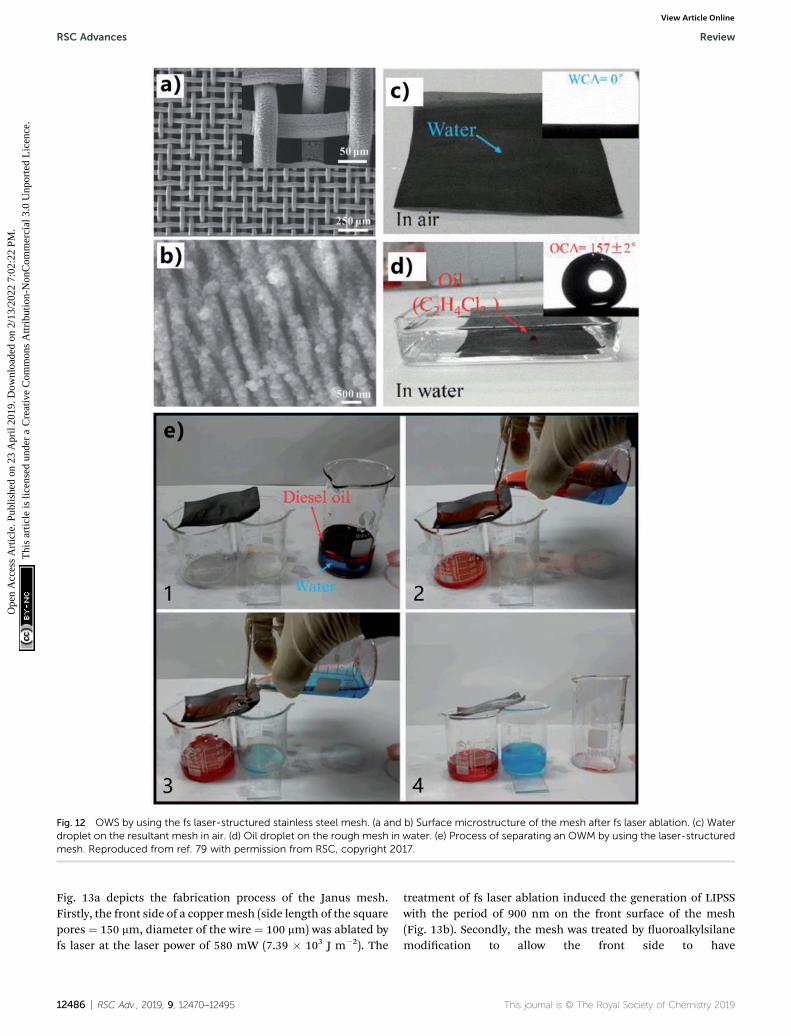
Fig. 12 OWS by using the fs laser-structured stainless steel mesh. (a and b) Surface microstructure of the mesh after fs laser ablation. (c) Waterdroplet on the resultant mesh in air. (d) Oil droplet on the rough mesh in water. (e) Process of separating an OWM by using the laser-structuredmesh. Reproduced from ref. 79 with permission from RSC, copyright 2017.
RSC Advances Review
Ope
n A
cces
s A
rtic
le. P
ublis
hed
on 2
3 A
pril
2019
. Dow
nloa
ded
on 2
/13/
2022
7:0
2:22
PM
. T
his
artic
le is
lice
nsed
und
er a
Cre
ativ
e C
omm
ons
Attr
ibut
ion-
Non
Com
mer
cial
3.0
Unp
orte
d L
icen
ce.
View Article Online
Fig. 13a depicts the fabrication process of the Janus mesh.Firstly, the front side of a copper mesh (side length of the squarepores ¼ 150 mm, diameter of the wire ¼ 100 mm) was ablated byfs laser at the laser power of 580 mW (7.39 � 103 J m�2). The
12486 | RSC Adv., 2019, 9, 12470–12495
treatment of fs laser ablation induced the generation of LIPSSwith the period of 900 nm on the front surface of the mesh(Fig. 13b). Secondly, the mesh was treated by uoroalkylsilanemodication to allow the front side to have
This journal is © The Royal Society of Chemistry 2019

Fig. 13 Selective OWS by using a laser-structured Janus mesh. (a) Schematic diagram of the process of fabricating the Janus mesh. Upper insetshows an in-air water droplet on the fluoroalkylsilane modified side and the lower inset presents an underwater oil droplet on the GO modifiedside. (b) SEM image of the fluoroalkylsilane modified side of the mesh. (c) Surface microstructure of the GO modified side of the mesh. (d)Separation of themixture of water and light oil (bean oil) by the Janus mesh with the fluoroalkylsilanemodified side facing upward. (e) Separationof the mixture of water (pink color) and heavy oil (CCl4) by the Janus mesh with the GO modified side facing upward. (f and g) Schematic of theselective separation process: (f) separating the mixture of water and light oil, (g) separating the mixture of water and heavy oil. (h) Water dropletrolling on the fluoroalkylsilane modified mesh. (i) Oil wetting the fluoroalkylsilane modified mesh in air. (j) Water wetting the GO modified mesh.(k) Underwater oil droplet rolling on the GO modified mesh. Reproduced from ref. 80 with permission from RSC, copyright 2017.
Review RSC Advances
Ope
n A
cces
s A
rtic
le. P
ublis
hed
on 2
3 A
pril
2019
. Dow
nloa
ded
on 2
/13/
2022
7:0
2:22
PM
. T
his
artic
le is
lice
nsed
und
er a
Cre
ativ
e C
omm
ons
Attr
ibut
ion-
Non
Com
mer
cial
3.0
Unp
orte
d L
icen
ce.
View Article Online
superhydrophobicity. Water droplet on such front mesh surfaceshowed a WCA of 160� (inset of Fig. 13a) and could roll away onthe 2� tilted mesh (Fig. 13h), while oil droplet directly spreadout the front mesh aer coming in contact with the mesh(Fig. 13i). Thirdly, the mesh's backside was ablated by fs laser ata relatively low laser power (100 mW, 1.27 � 103 J m�2) to notonly remove the residual uoroalkylsilane on the backside butalso generate worm-like ripples on the back surface of the mesh(Fig. 13c). Finally, the rough back side was modied with a layerof GO via the dip coating method, ensuring that the worm-likenanoripples were well identied from the laser-treatedsubstrate. Since the GO was rich in hydrophilic oxygen groups(such as hydroxyl and carboxyl groups), the back surface of theresultant mesh became superhydrophilic in air (Fig. 13j). Aerthe immersion of the mesh in water, the back side exhibitedsuperoleophobicity with OCA of 161� to an n-hexane droplet(inset of Fig. 13a). Underwater oil droplet could also easily rolloff the back side of the mesh with a slight tilted angle (Fig. 13k).Therefore, the as-prepared mesh showed Janus wettabilitybecause its one side was superhydrophobic/superoleophilic andanother side was superhydrophilic/underwatersuperoleophobic.
By using the Janus mesh, selective gravity-driven separationof the mixtures of water and no matter heavy or light oils wasachieved. They found the intrusion pressure played a signicantrole in different types of OWS. In the case of a light oil (bean oil),
This journal is © The Royal Society of Chemistry 2019
the mesh was sandwiched between two plastic tubes and theuoroalkylsilane modied side faced upward. Aer the OWMbeing added into the separating device, it could be observedthat only water passed through the Janus mesh (Fig. 13d). Asshown in Fig. 13f, the superhydrophobic side was rstly contactwith the mixture. There was a hydrostatic pressure pushing thewater to penetrate the mesh but a hydrophobic force resistingthis penetration. For a much small hydrostatic pressure, theseparation would not start because the superhydrophobicityprevented the mixture from permeating through the mesh.Therefore, the hydrostatic pressure must be large enough.When water penetrated into the pores of the mesh deeply andmade in contact with the hydrophilic region beneath, the waterwould entirely pass through the mesh and fully wetted thesuperhydrophilic side by the capillary effect, forming a waterlayer on the superhydrophilic side beneath. Oil was able to wetthe superhydrophobic side of the Janus mesh but was blockedby the superhydrophilic/underwater superoleophobic side, sothe mesh could support a certain height of the oils. Regardingthe mixture of water and heavy oils (e.g., CCl4), the GO modiedside needed to face upward, allowing the oil to rst contact withthe mesh. It could be observed that only oil phase in the mixturecould pass through the Janus mesh (Fig. 13e). As shown inFig. 13g, the oil was able to wet the surface and penetrate easilydue to the in-air oleophilicity of both the GO modied side andthe uoroalkylsilane modied side. When the water phase also
RSC Adv., 2019, 9, 12470–12495 | 12487

RSC Advances Review
Ope
n A
cces
s A
rtic
le. P
ublis
hed
on 2
3 A
pril
2019
. Dow
nloa
ded
on 2
/13/
2022
7:0
2:22
PM
. T
his
artic
le is
lice
nsed
und
er a
Cre
ativ
e C
omm
ons
Attr
ibut
ion-
Non
Com
mer
cial
3.0
Unp
orte
d L
icen
ce.
View Article Online
touched the oil-wetted mesh, it wet the GO modied side due tothe superhydrophilicity but did not pass through the super-hydrophobic below half part. The mesh could support a certainpressure of water. Therefore, both the light OWM and the heavyOWM can be selectively separated as long as a proper side of theJanus mesh faces up.
Although many Janus membranes with asymmetric wetta-bilities have been reported and applied in oil/water separation,in most cases, the Janus membranes are prepared by theselective modication of one side, sequential decoration, ordirectly combining twomembranes together.204–208 Compared tothe common methods, fs laser microfabrication is able to getprecise control over the surface micro/nanostructures and thechemical composition on both sides of porous mesh/membranes synchronously, which shows great advantages inachieving distinct wetting behaviors on the two sides of theJanus membrane.
3.4 Selective oil/water separation
Lian et al. reported a simple method to realize selective light orheavy OWS by using the nanosecond laser ablated brass mesh.81
A low-cost nanosecond laser marking system (pulse width of 100ns, Q frequency ¼ 20 kHz) was adopted to generate roughtexture on the surface of the mesh based on the LBL scanningprocess. The surface of the original bare brass mesh (200 meshsize) is smooth (Fig. 14a). The nanosecond laser ablationresulted in a coating layer of micro/nanoscale binary structureon the wire of the mesh (Fig. 14b). The pore size of the meshalso decreased from 75 mm to 65 mm due to the formation of therough surface microstructures on the wires (Fig. 14a and b). Inaddition, O element was found to appear on the resultantsurface, indicating that metal oxidation happened during laserablation. Laser ablation made the mesh exhibit super-hydrophilicity and superoleophilicity simultaneously in air.When water and oil (kerosene) droplets was dripped onto theresultant mesh, they would spread out quickly aer just contact,resulting in a WCA below 10� and an OCA of about 0�. If themesh was immersed in liquid phase, the wettability of the as-prepared mesh would change obviously. Fig. 14c shows an oil(1,2-dichloroethane) droplet on the laser-treated mesh under-water. The oil droplet looked like a sphere with an OCA of157.5�, revealing that the mesh was superoleophobic in water.The superoleophobicity was ascribed to the underwater Cassiewetting of the oil on the rough mesh. Similarly, for the case ofthe rough mesh in oil (kerosene), water droplet that was put onthe mesh showed a WCA of 156.3�; that is, the laser-treatedmesh also had underoil superhydrophobicity (Fig. 14d). Whenthe rough mesh was submerged in oil, the oil would rapidly wetthe mesh due to the superoleophilicity of the mesh and an oillayer would be trapped in the hierarchical microstructures. Theunderoil water droplets on the mesh were strongly repelled bysuch trapped oil cushion which dramatically decreased thecontact area between the mesh surface and the water droplets,resulting in the underoil superhydrophobicity of the texturedmesh. The underwater superoleophobicity as well as theunderoil superhydrophobicity of the laser-ablated mesh was
12488 | RSC Adv., 2019, 9, 12470–12495
valid for many different oils, including kerosene, soybean oil,dodecane, chloroform, and 1,2-dichloroethane. Based on thespecial wettability (underwater superoleophobicity and under-oil superhydrophobicity), the resultant mesh was able to selec-tively separate the light or heavy OWMs. The separating devicemay not seem very different from the above-mentioned setup bysandwiching the separating membrane between two tubes(Fig. 14e and f). The key here is to correctly wet the mesh inadvance. Regarding the mixture of kerosene (light oil) andwater, the mesh needed to be previously wetted by a little water.When themixture was added into the upper tube, only the waterphase in the mixture could pass through the pre-wetted meshand be collected in the below container while the oil phase washeld back (Fig. 14e). Aer the separation, the mesh was cleanedwith ethanol and was able to further separate the mixture of 1,2-dichloroethane (heavy oil) and water. In this case, the meshneeded to be wetted by a small amount of oil. Aer the mixturebeing added into the separating device, the oil could penetratethrough the pre-wetted mesh, and there was no water appearingin the collected oil (Fig. 14f). Also, the mesh was easily switchedto separate light OWM again aer cleaning with ethanol. Theunderwater superoleophobicity endowed the water-wettedmesh with the ability to separate light OWMs, whereas theunderoil superhydrophobicity allowed the oil-wetted mesh toseparate heavy OWMs. The switch between those two separatingways could be repeated for at least ve cycles with high sepa-ration efficiency.
Although nanosecond laser was utilized to rough the meshsurface in the above example, we believe the surface micro-structures and the special wettability can also be created by fslaser through the same treatment. The fs laser-textured meshwith underwater superoleophobicity and underoil super-hydrophobicity is also able to selectively separate OWM, like theabove example. Therefore, we loosely introduce this examplehere and we can predict that the similar method for selectiveOWS based on the fs laser-induced super-wetting porousmaterials will be reported within the next year or two.
3.5 Oil-absorption 3D materials
Different from the superwetting separating mesh/membranes,superhydrophobic and superoleophilic 3D porous bulk mate-rials can directly absorb oils from no matter water surface orunderwater, thereby the contaminated oils are completelyremoved from the OWM and be collected for reuse.190,192,195–203
Oil-absorption 3D materials are better than separatingmembranes in some special cases towards achieving efficientOWS, such as leaked heavy oils, a small amount of oil beingleaked to sea surface, etc. However, laser ablation is not suit toprocess uneven surface, especially for 3D materials such asfoam, sponge, etc. Fortunately, 2Dmembrane can be folded intoa 3D shape, similar to origami. Zhang et al. proposed a methodto make the fs laser-structured 2D foil become a 3D oil-absorption barrel.62 They fabricated a tapered microholes-structured Janus oil barrel by fs laser micro-drilling, uo-roalkylsilane modication, laser scanning the lower surface,and assembling. Such novel oil barrel had a superhydrophilic
This journal is © The Royal Society of Chemistry 2019

Fig. 14 Selective OWS by using the nanosecond laser-ablated brass mesh as the separating membrane. (a) Morphology of the untreated barebrass mesh. (b) Surface microstructure of the brass mesh after nanosecond laser treatment. (c) Underwater superoleophobicity of the laser-induced rough mesh. (d) Underoil superhydrophobicity of the rough mesh. (e) Separation of light oil (kerosene) and water by using the water-wetted roughmesh. (f) Separation of heavy oil (1,2-dichloroethane) and water by using the oil-wetted roughmesh. Reproduced from ref. 81 withpermission from ACS, copyright 2018.
Review RSC Advances
Ope
n A
cces
s A
rtic
le. P
ublis
hed
on 2
3 A
pril
2019
. Dow
nloa
ded
on 2
/13/
2022
7:0
2:22
PM
. T
his
artic
le is
lice
nsed
und
er a
Cre
ativ
e C
omm
ons
Attr
ibut
ion-
Non
Com
mer
cial
3.0
Unp
orte
d L
icen
ce.
View Article Online
inside wall and a superhydrophobic outside wall, which couldefficiently remove oil from water surface. Fig. 15a shows thepreparation process. Firstly, a uniform microholes array wasfabricated on an aluminum foil by using fs laser micro-drilling(i.e., PBP ablation) (Step 1). The location of the ablation pointswas precisely controlled by a high-speed galvanometer scanner.The diameter of the focus spot of the fs laser beam was�20 mm,and that of the generated microholes could be adjusted from14.05 to 31.3 mm by changing the laser pulse energy and thepulse number. The period of the microholes array was set at 100mm. Both the upper and the lower surfaces of the treatedaluminum foil showed superhydrophilicity aer laser drilling(le column of Fig. 15c). Secondly, the wettability of the foil wasswitched from superhydrophilicity to superhydrophobicity bythe uoroalkylsilane modication (Step 2). As a result, the waterdroplets on the upper surface and lower surface of the foil hadthe WCA values of 166.7� and 158.4�, respectively (middlecolumn of Fig. 15c). Aer that, only the lower surface was
This journal is © The Royal Society of Chemistry 2019
ablated by fs laser via the LBL scanning process (Step 3). Suchtreatment is ameans to remove the uorination composition onthe lower surface. Fig. 15b shows the microstructures of bothside of the as-prepared foil, respectively. Surrounding area ofthe microholes on the upper surface was completely coveredwith microscale fragments (2 to 10 mm), while that on the lowersurface was covered with nanoscale protuberances (0.2 to 1 mm).The cross-section SEM image shows that the fabricated micro-holes had a tapered morphology with the taper angle of 25–30�,resulting from the Gaussian laser ablation (inset of Fig. 15a).There were a lot of micro/nanoscale wrinkles distributing on themicroholes' inner wall. Aer the 3rd step, the upper surfacemaintained its superhydrophobicity with the WCA of 158.4� butthe lower surface changed to superhydrophilicity with the WCAof 4.2� (right column of Fig. 15c). In addition, the upper surfaceexhibited superoleophilicity (OCA ¼ 5.4�) in air, and the lowersurface exhibited superoleophilicity (OCA ¼ �0�) in air andunderwater superoleophobicity (OCA ¼ �150.7�). As a result,
RSC Adv., 2019, 9, 12470–12495 | 12489

Fig. 15 Oil absorption based on a Janus oil barrel (superhydrophilic inside wall and superhydrophobic outside wall). (a) Preparation process ofthe Janus oil barrel: Step 1, fs laser micro-drilling; Step 2, fluoroalkylsilane modification; Step 3, laser scanning on the lower surface; and Step 4and 5, assembling. (b) SEM images of the two side of the resultant aluminum foil. (c) Water contact angles of the treated upper surface and thelower surface after different steps. (d) Process of absorbing oil from water surface by using the Janus oil barrel. Reproduced from ref. 62 withpermission from RSC, copyright 2017.
RSC Advances Review
Ope
n A
cces
s A
rtic
le. P
ublis
hed
on 2
3 A
pril
2019
. Dow
nloa
ded
on 2
/13/
2022
7:0
2:22
PM
. T
his
artic
le is
lice
nsed
und
er a
Cre
ativ
e C
omm
ons
Attr
ibut
ion-
Non
Com
mer
cial
3.0
Unp
orte
d L
icen
ce.
View Article Online
the as-prepared aluminum foil had not only different surfacemicrostructures but also different surface wettabilities on bothsides, showing a Janus feature.
An oil barrel was easily assembled by curling the exibleJanus porous aluminum foil (4th and 5th steps in Fig. 15a). The
12490 | RSC Adv., 2019, 9, 12470–12495
as-prepared Janus barrel had a superhydrophobic/superoleophilic outside wall and a superhydrophilic/underwater superoleophobic inside wall. Such Janus barrelshowed great oil-absorption and storage capacity towards col-lecting spilled oil. The inside wall was pre-wetted by a little
This journal is © The Royal Society of Chemistry 2019

Review RSC Advances
Ope
n A
cces
s A
rtic
le. P
ublis
hed
on 2
3 A
pril
2019
. Dow
nloa
ded
on 2
/13/
2022
7:0
2:22
PM
. T
his
artic
le is
lice
nsed
und
er a
Cre
ativ
e C
omm
ons
Attr
ibut
ion-
Non
Com
mer
cial
3.0
Unp
orte
d L
icen
ce.
View Article Online
water before use. As shown in Fig. 15d, once the Janus barrel(diameter of the microholes ¼ 40.3 mm, interval of the micro-holes ¼ 100 mm) was put into a beaker that was lled with themixture of 600 mL water (blue color) and 30 mL oil (octane, redcolor), the oil-absorption process would start instantly underthe capillary force. The barrel was lled by absorbed oil grad-ually. In addition, no water was found in the oil barrel becausethe superhydrophobic outside wall was able to prevent waterfrom entering into the barrel. About 33 s later, all the spilled oilwas absorbed and collected in the barrel. Meanwhile, themuddy OWM in original beaker turned to very clear. It wasdemonstrated that the oil-absorption speed increased with theincrease of the diameter of the microholes. The average uxreached up to 45 000 L m�2 h�1 for the Janus foil with the holediameter of 40.3 mm. Interestingly, the Janus oil barrel also hadthe ability to eliminate secondary leakage. The absorbed/collected oil could not ow out of the barrel because the oilwas blocked by the underwater superoleophobic inside wall. Incontrast, the oil that was absorbed into a common barrel withsuperhydrophobicity on its both sides could also ow out fromthe barrel. In addition to the advantages of high efficiency, highux, high intrusion pressure, large absorption and storagecapacity, the Janus barrel could also remove oils in oil-in-wateremulsions.
4. Conclusions and perspective
OWS is a global challenge in the aspect of protecting ecologicalenvironment and reducing the economic loss caused by the oilspill and the discharge of oily wastewater. Recently, porousmaterials with superhydrophobicity or superoleophobicity havebeen developed to efficiently separate various OWMs, becauseOWS is actually an interfacial issue. Due to the features of smallheat-affected zone, high spatial resolution, extensive materialprocessing, and non-contact manufacturing, fs laser micro-fabrication has been successfully applied to design extremewettability on various material surfaces. Such technology is ableto not only process a broad range of substrate materials but alsocreate both large-area micro/nanoscale hierarchical structuresand perforating microholes array on a thin lm. In this review,we mainly summarize the recent applications of the fs laser-structured superhydrophobic or underwater superoleophobicporous materials in OWS. Inspired by lotus leaf and sh scale,superhydrophobicity and underwater superoleophobicity arerespectively achieved on the surfaces of various materials bycombining fs laser-designed surface microstructures andhydrophobic/hydrophilic chemistry. The diversity of the surfacewettabilities of the fs laser-structured materials endows thesematerials with the ability to separate OWMs in a variety of ways.The practical oil/water separating application of the fs laser-induced superwetting porous materials is introduced indetail, including the wettability, separating method/operation,and the separation mechanism of each case.
The research related to the fs laser-structured oil/waterseparating materials was rst reported in 2016, and iscurrently still in its infancy. Many problems and challengesshould be solved in the coming years. Firstly, the efficiency of
This journal is © The Royal Society of Chemistry 2019
fabricating superwetting porous materials needs to beimproved because it is important for large-scale real OWS. Moreadvanced laser-ablation manner (e.g., processing based ona cylindrical focusing lens, automatic parallel processing) andthe laser system with higher power are eagerly awaited.Secondly, poor mechanical/chemical durability usually resultsin the decline of the surface superwettability as well as the oil/water separating capacity of the separating materials aerseveral cycles of use. Endowing those materials with durablesuperhydrophobicity and superoleophobicity can extend theirservice life. Thirdly, the oil contaminants in a real condition areusually very complex rather than the pure oily liquids that areused in the proof-of-concept separation experiments. Forexample, high-viscosity and high-density oils will potentiallyfoul the separating materials or block the micropores of thesubstrate, weakening the separation ability of the fabricatedmaterials. There also exist many different kinds of oil/wateremulsions. The materials and methods for separating thecomplex mixtures of water and high-viscosity oils and theemulsions are required to be further developed. Fourthly, moreresearches need to be focused on understanding the dynamicinteraction between the superwetting porous substrate and theOWM. Such interaction mechanism has a positive role indesigning and fabricating various separating materials, as wellas the use of those materials to achieve efficient OWS. Finally,and perhaps most importantly, researchers should attempt tobring the fs laser-induced superwetting porous materials tomarket and design practical large instrument by using those oil/water separating materials as the core components in thefuture, practically preventing the environmental pollutioncaused by the discharge of oily industrial wastewater and oilspills.
It could be expected that the development trend of OWS willhave an explosive growth towards the design of materials andthe separating methods. We believe that the advanced featuresof fs laser microfabrication will lead to an exciting future in theeld of OWS.
Conflicts of interest
There are no conicts to declare.
Acknowledgements
This work is supported by the National Key Research andDevelopment Program of China under the Grant no.2017YFB1104700, the Bill & Melinda Gates Foundation underthe Grant no. OPP1119542, the National Science Foundation ofChina under the Grant no. 51335008, 61875158, and 61805192,China Postdoctoral Science Foundation under the Grant no.2016M600786, the Collaborative Innovation Center of SuzhouNano Science and Technology, and the International JointResearch Laboratory for Micro/Nano Manufacturing andMeasurement Technologies.
RSC Adv., 2019, 9, 12470–12495 | 12491

RSC Advances Review
Ope
n A
cces
s A
rtic
le. P
ublis
hed
on 2
3 A
pril
2019
. Dow
nloa
ded
on 2
/13/
2022
7:0
2:22
PM
. T
his
artic
le is
lice
nsed
und
er a
Cre
ativ
e C
omm
ons
Attr
ibut
ion-
Non
Com
mer
cial
3.0
Unp
orte
d L
icen
ce.
View Article Online
References
1 Z. Xue, Y. Cao, N. Liu, L. Feng and L. Jiang, J. Mater. Chem. A,2014, 2, 2445.
2 B. Wang, W. Liang, Z. Guo and W. Liu, Chem. Soc. Rev.,2015, 44, 336.
3 R. K. Gupta, G. J. Dunderdale, M. W. England andA. Hozumi, J. Mater. Chem. A, 2017, 5, 16025.
4 Z. Chu, Y. Feng and S. Seeger, Angew. Chem., Int. Ed., 2015,54, 2328.
5 J. L. Yong, J. Huo, F. Chen, Q. Yang and X. Hou, Phys. Chem.Chem. Phys., 2018, 20, 25140.
6 J. L. Yong, F. Chen, Q. Yang, G. Du, C. Shan, J. Huo, Y. Fangand X. Hou, Adv. Mater. Interfaces, 2016, 3, 1500650.
7 J. L. Yong, F. Chen, J. Huo, Y. Fang, Q. Yang, H. Bian, W. Li,Y. Wei, Y. Dai and X. Hou, ACS Omega, 2018, 3, 1395.
8 C.-F. Wang, F.-S. Tzeng, H.-G. Chen and C.-J. Chang,Langmuir, 2012, 28, 10015.
9 K. Li, J. Ju, Z. Xue, J. Ma, L. Feng, S. Gao and L. Jiang, Nat.Commun., 2013, 4, 2276.
10 https://en.wikipedia.org/wiki/Deepwater_Horizon_oil_spill.
11 L. Feng, Z. Zhang, Z. Mai, Y. Ma, B. Liu, L. Jiang and D. Zhu,Angew. Chem., Int. Ed., 2004, 43, 2012.
12 S. Wang, Y. Song and L. Jiang, Nanotechnology, 2007, 18,015103.
13 J. Song, S. Huang, Y. Lu, X. Bu, J. E. Mates, A. Ghosh,R. Ganguly, C. J. Carmalt, I. P. Parkin, W. Xu andC. M. Megaridis, ACS Appl. Mater. Interfaces, 2014, 6, 19858.
14 J. Y. Huang, S. H. Li, M. Z. Ge, L. N. Wang, T. L. Xing,G. Q. Chen, X. F. Liu, S. S. Al-Deyab, K. Q. Zhang, T. Chenand Y. K. Lai, J. Mater. Chem. A, 2015, 3, 2825.
15 C.-H. Xue, Y.-R. Li, J.-L. Hou, L. Zheng and J.-Z. Ma, J. Mater.Chem. A, 2015, 3, 10248.
16 J. L. Yong, Y. Fang, F. Chen, J. Huo, Q. Yang, H. Bian, G. Duand X. Hou, Appl. Surf. Sci., 2016, 389, 1148.
17 L.-H. Kong, X.-H. Chen, L.-G. Yu, Z.-S. Wu and P.-Y. Zhang,ACS Appl. Mater. Interfaces, 2015, 7, 2616.
18 J. Li, R. Kang, X. Tang, H. She, Y. Yang and F. Zha,Nanoscale, 2016, 8, 7638.
19 Z. Xue, S. Wang, L. Lin, L. Chen, M. Liu, L. Feng andL. Jiang, Adv. Mater., 2011, 23, 4270.
20 Q. Zhu, Q. Pan and F. Liu, J. Phys. Chem. C, 2011, 115,17464.
21 F. Zhang, W. B. Zhang, Z. Shi, D. Wang, J. Jin and L. Jiang,Adv. Mater., 2013, 25, 4192.
22 Q. Wen, J. Di, L. Jiang, J. Yu and R. Xu, Chem. Sci., 2013, 4,591.
23 S.-J. Choi, T.-H. Kwon, H. Im, D.-I. Moon, D. J. Baek,M.-L. Seol, J. P. Duarte and Y.-K. Choi, ACS Appl. Mater.Interfaces, 2011, 3, 4552.
24 X. Gao, L.-P. Xu, Z. Xue, L. Feng, J. Peng, Y. Wen, S. Wangand X. Zhang, Adv. Mater., 2014, 26, 1771.
25 M. Tao, L. Xue, F. Liu and L. Jiang, Adv. Mater., 2014, 26,2943.
12492 | RSC Adv., 2019, 9, 12470–12495
26 Y.-Q. Liu, Y.-L. Zhang, X.-Y. Fu and H.-B. Sun, ACS Appl.Mater. Interfaces, 2015, 7, 20930.
27 L. Zhang, Y. Zhong, D. Cha and P. Wang, Sci. Rep., 2013, 3,2326.
28 G. Li, H. Fan, F. Ren, C. Zhou, Z. Zhang, B. Xu, S. Wu, Y. Hu,W. Zhu, J. Li, Y. Zeng, X. Li, J. Chu and D. Wu, J. Mater.Chem. A, 2016, 4, 18832.
29 Z. Yu, F. Yun, Z. Gong, Q. Yao, S. Dou, K. Liu, L. Jiang andX. Wang, J. Mater. Chem. A, 2017, 5, 10821.
30 Q. Zhu and Q. Pan, ACS Nano, 2014, 8, 1402.31 R. Du, X. Gao, Q. Feng, Q. Zhao, P. Li, S. Deng, L. Shi and
J. Zhang, Adv. Mater., 2016, 28, 936.32 C. Cao, M. Ge, J. Huang, S. Li, S. Deng, S. Zhang, Z. Chen,
K. Zhang, S. S. Al-Deyab and Y. Lai, J. Mater. Chem. A,2016, 4, 12179.
33 L. Su, H. Wang, M. Niu, X. Fan, M. Ma, Z. Shi and S.-W. Guo,ACS Nano, 2018, 12, 3103.
34 Z. Cheng, H. Lai, Y. Du, K. Fu, R. Hou, N. Zhang and K. Sun,ACS Appl. Mater. Interfaces, 2013, 5, 11363.
35 D. Tian, X. Zhang, Y. Tian, Y. Wu, X. Wang, J. Zhai andL. Jiang, J. Mater. Chem., 2012, 22, 19652.
36 Z. Cheng, H. Lai, Y. Du, K. Fu, R. Hou, C. Li, N. Zhang andK. Sun, ACS Appl. Mater. Interfaces, 2014, 6, 636.
37 Y. Yu, H. Chen, Y. Liu, V. Craig, L. H. Li and Y. Chen, Adv.Mater. Interfaces, 2014, 1, 1300002.
38 L. Li, Z. Liu, Q. Zhang, C. Meng, T. Zhang and J. Zhai, J.Mater. Chem. A, 2015, 3, 1279.
39 W. Zhang, Y. Zhu, X. Liu, D. Wang, J. Li, L. Jiang and J. Jin,Angew. Chem., Int. Ed., 2015, 53, 856.
40 E. Zhang, Z. Cheng, T. Lv, Y. Qian and Y. Liu, J. Mater. Chem.A, 2015, 3, 13411.
41 Y. Dong, J. Li, L. Shi, X. Wang, Z. Guo and W. Liu, Chem.Commun., 2014, 50, 5586.
42 J. Li, L. Yan, H. Li, W. Li, F. Zha and Z. Lei, J. Mater. Chem. A,2015, 3, 14696.
43 Z. Cheng, J. Wang, H. Lai, Y. Du, R. Hou, C. Li, N. Q. Zhangand K. N. Sun, Langmuir, 2015, 31, 1393.
44 Y. Cao, X. Zhang, L. Tao, K. Li, Z. Xue, L. Feng and Y. Wei,ACS Appl. Mater. Interfaces, 2013, 5, 4438.
45 S. Li, J. Huang, M. Ge, C. Cao, S. Deng, S. Zhang, G. Chen,K. Zhang, S. S. Al-Deyab and Y. Lai, Adv. Mater. Interfaces,2015, 2, 1500220.
46 J. Li, D. Li, Y. Yang, J. Li, F. Zha and Z. Lei, Green Chem.,2016, 18, 541.
47 J. L. Yong, F. Chen, Q. Yang and X. Hou, So Matter, 2015,11, 8897.
48 F. Chen, D. Zhang, Q. Yang, J. Yong, G. Du, J. Si, F. Yun andX. Hou, ACS Appl. Mater. Interfaces, 2013, 5, 6777.
49 J. L. Yong, F. Chen, Q. Yang, D. Zhang, U. Farooq, G. Du andX. Hou, J. Mater. Chem. A, 2014, 2, 8790.
50 J. L. Yong, Q. Yang, F. Chen, D. Zhang, U. Farooq, G. Du andX. Hou, J. Mater. Chem. A, 2014, 2, 5499.
51 J. L. Yong, F. Chen, Q. Yang, G. Du, C. Shan, H. Bian,U. Farooq and X. Hou, J. Mater. Chem. A, 2015, 3, 9379.
52 D. Zhang, F. Chen, Q. Yang, J. L. Yong, H. Bian, Y. Ou, J. Si,X. Meng and X. Hou, ACS Appl. Mater. Interfaces, 2012, 4,4905.
This journal is © The Royal Society of Chemistry 2019

Review RSC Advances
Ope
n A
cces
s A
rtic
le. P
ublis
hed
on 2
3 A
pril
2019
. Dow
nloa
ded
on 2
/13/
2022
7:0
2:22
PM
. T
his
artic
le is
lice
nsed
und
er a
Cre
ativ
e C
omm
ons
Attr
ibut
ion-
Non
Com
mer
cial
3.0
Unp
orte
d L
icen
ce.
View Article Online
53 J. L. Yong, Q. Yang, F. Chen, H. Bian, G. Du, U. Farooq andX. Hou, Adv. Mater. Interfaces, 2015, 2, 1400388.
54 J. L. Yong, F. Chen, Q. Yang, Y. Fang, J. Huo and X. Hou,Chem. Commun., 2015, 51, 9813.
55 J. L. Yong, F. Chen, Q. Yang, Y. Fang, J. Huo, J. Zhang andX. Hou, Adv. Mater. Interfaces, 2017, 4, 1700552.
56 K. Sugioka and Y. Cheng, Appl. Phys. Rev., 2014, 1, 041303.57 T. C. Chong, M. H. Hong and L. P. Shi, Laser Photonics Rev.,
2010, 4, 123.58 K. Sugioka and Y. Cheng, Light: Sci. Appl., 2014, 3, e149.59 A. Y. Vorobyev and C. Guo, Laser Photonics Rev., 2013, 7, 385.60 D. B. Wolfe, J. B. Ashcom, J. C. Hwang, C. B. Schaffer,
E. Mazur and G. M. Whitesides, Adv. Mater., 2003, 15, 62.61 J. L. Yong, F. Chen, Q. Yang, U. Farooq and X. Hou, J. Mater.
Chem. A, 2015, 3, 10703.62 Z. Zhang, Y. Zhang, H. Fan, Y. Wang, C. Zhou, F. Ren, S. Wu,
G. Li, Y. Hu, J. Li, D. Wu and J. Chu, Nanoscale, 2017, 9,15796.
63 Y. Lee, S.-H. Park, K.-B. Kim and J.-K. Lee, Adv. Mater., 2007,19, 2330.
64 X. Yao, Y. Song and L. Jiang, Adv. Mater., 2011, 23, 719.65 K. Liu, X. Yao and L. Lei, Chem. Soc. Rev., 2010, 39, 3240.66 Y. Tian, B. Su and L. Jiang, Adv. Mater., 2014, 26, 6872.67 L. Wen, Y. Tian and L. Lei, Angew. Chem., Int. Ed., 2015, 54,
3387.68 H. Bellanger, T. Darmanin, E. T. de Givenchy and
F. Guittard, Chem. Rev., 2014, 114, 2694.69 J.-N. Wang, Y.-L. Zhang, Y. Liu, W. Zheng, L. P. Lee and
H.-B. Sun, Nanoscale, 2015, 7, 7101.70 J. L. Yong, F. Chen, Q. Yang, J. Huo and X. Hou, Chem. Soc.
Rev., 2017, 46, 4168.71 M. Liu, S. Wang and L. Jiang, Nat. Rev. Mater., 2017, 2,
17036.72 B. Su, Y. Tian and L. Jiang, J. Am. Chem. Soc., 2016, 138,
1727.73 J. L. Yong, F. Chen, Q. Yang, Z. Jiang and X. Hou, Adv. Mater.
Interfaces, 2018, 5, 1701370.74 J. L. Yong, Q. Yang, F. Chen, D. Zhang, H. Bian, Y. Ou, J. Si,
G. Du and X. Hou, Appl. Phys. A, 2013, 111, 243.75 J. L. Yong, Q. Yang, F. Chen, D. Zhang, G. Du, H. Bian, J. Si,
F. Yun and X. Hou, Appl. Surf. Sci., 2014, 288, 579.76 J. L. Yong, Q. Yang, F. Chen, D. Zhang, G. Du, H. Bian, J. Si
and X. Hou, RSC Adv., 2014, 4, 8138.77 Y. Fang, J. Yong, F. Chen, J. Huo, Q. Yang, H. Bian, G. Du
and X. Hou, Appl. Phys. A, 2016, 122, 827.78 S. Ye, Q. Cao, Q. Wang, T. Wang and Q. Peng, Sci. Rep.,
2016, 6, 37591.79 K. Yin, D. Chu, X. Dong, C. Wang, J.-A. Duan and J. He,
Nanoscale, 2017, 9, 14229.80 Y.-Q. Liu, D.-D. Han, Z.-Z. Jiao, Y. Liu, H.-B. Jiang, X.-H. Wu,
H. Ding, Y.-L. Zhang and H.-B. Sun, Nanoscale, 2017, 9,17933.
81 Z. Lian, J. Xu, Z. Wang, Z. Yu, Z. Weng and H. Yu, Langmuir,2018, 34, 2981.
82 W. Barthlott and C. Neinhuis, Planta, 1997, 202, 1.
This journal is © The Royal Society of Chemistry 2019
83 V. Zorba, E. Stratakis, M. Barberoglou, E. Spanakis,P. Tzanetakis, S. H. Anastasiadis and C. Fotakis, Adv.Mater., 2008, 20, 4049.
84 J. L. Yong, F. Chen, Y. Fang, J. Huo, Q. Yang, J. Zhang,H. Bian and X. Hou, ACS Appl. Mater. Interfaces, 2017, 9,39863.
85 S. Wang and L. Jiang, Adv. Mater., 2007, 19, 3423.86 J. L. Yong, F. Chen, M. Li, Q. Yang, Y. Fang, J. Huo and
X. Hou, J. Mater. Chem. A, 2017, 5, 25249.87 I. A. Larmour, S. E. J. Bell and G. C. Saunders, Angew. Chem.,
2007, 119, 1740.88 Y. Zhao, Y. Tang, X. Wang and T. Lin, Appl. Surf. Sci., 2010,
256, 6736.89 D. J. Babu, M. Mail, W. Barthlott and J. J. Schneider, Adv.
Mater. Interfaces, 2017, 4, 1700273.90 X. Gao and L. Jiang, Nature, 2004, 432, 36.91 D. L. Hu, B. Chan and J. W. Bush, Nature, 2003, 424, 663.92 L. Feng, Y. Zhang, J. Xi, Y. Zhu, N. Wang, F. Xia and L. Jiang,
Langmuir, 2008, 24, 4114.93 L. Feng, S. Li, Y. Li, H. Li, L. Zhang, J. Zhai, Y. Song, B. Liu,
L. Jiang and D. Zhu, Adv. Mater., 2002, 14, 1857.94 D. Wu, J.-N. Wang, S.-Z. Wu, Q.-D. Chen, S. Zhao, H. Zhang,
H.-B. Sun and L. Jiang, Adv. Funct. Mater., 2011, 21, 2927.95 Y. Zheng, X. Guo and L. Jiang, So Matter, 2007, 3, 178.96 X. Gao, X. Yan, X. Yao, L. Xu, K. Zhang, J. Zhang, B. Yang
and L. Jiang, Adv. Mater., 2007, 19, 2213.97 K. Liu, J. Du, J. Wu and L. Jiang, Nanoscale, 2012, 4, 768.98 W. Barthlott, T. Schimmel, S. Wiersch, K. Koch, M. Brede,
M. Barczewski, S. Walheim, A. Weis, A. Kaltenmaier,A. Leder and H. F. Bohn, Adv. Mater., 2010, 22, 2325.
99 A. R. Parker and C. R. Lawrence, Nature, 2001, 411, 33.100 M. Liu, S. Wang, Z. Wei, Y. Song and L. Jiang, Adv. Mater.,
2009, 21, 665.101 X. Liu, J. Zhou, Z. Xue, J. Gao, J. Meng, S. Wang and L. Jiang,
Adv. Mater., 2012, 24, 3401.102 Q. Cheng, M. Li, Y. Zheng, B. Zheng, B. Su, S. Wang and
L. Jiang, So Matter, 2011, 7, 5948.103 Y. Cai, Q. Lu, X. Guo, S. Wang, J. Qiao and L. Jiang, Adv.
Mater., 2015, 27, 4162.104 Y. Cai, L. Lin, Z. Xue, M. Liu, S. Wang and L. Jiang, Adv.
Funct. Mater., 2014, 24, 809.105 G. Wen, Z. Guo and W. Liu, Nanoscale, 2017, 9, 3338.106 J. Li, Z. Jing, F. Zha, Y. Yang, Q. Wang and Z. Lei, ACS Appl.
Mater. Interfaces, 2014, 6, 8868.107 Y. Zhang, Y. Chen, L. Shi, J. Li and Z. Guo, J. Mater. Chem.,
2012, 22, 799.108 Z. Cheng, M. Du, H. Lai, N. Zhang and K. Sun, Nanoscale,
2013, 5, 2776.109 J. Li, X. Liu, Y. Ye, H. Zhou and J. Chen, J. Phys. Chem. C,
2011, 115, 4726.110 M. Liu and L. Jiang, Adv. Funct. Mater., 2010, 20, 3753.111 F. Xia and L. Jiang, Adv. Mater., 2008, 20, 2842.112 J. Genzer and K. Emenko, Biofouling, 2006, 22, 339.113 Y. Shi and Z. Guo, Nanoscale, 2015, 7, 5922.114 R. N. Wenzel, Ind. Eng. Chem., 1936, 28, 988.115 A. B. D. Cassie and S. Baxter, Trans. Faraday Soc., 1994, 40,
546.
RSC Adv., 2019, 9, 12470–12495 | 12493

RSC Advances Review
Ope
n A
cces
s A
rtic
le. P
ublis
hed
on 2
3 A
pril
2019
. Dow
nloa
ded
on 2
/13/
2022
7:0
2:22
PM
. T
his
artic
le is
lice
nsed
und
er a
Cre
ativ
e C
omm
ons
Attr
ibut
ion-
Non
Com
mer
cial
3.0
Unp
orte
d L
icen
ce.
View Article Online
116 S. Tian, L. Li, W. Sun, X. Xia, D. Han, J. Li and C. Gu, Sci.Rep., 2012, 2, 511.
117 K. Li, X. Zeng, H. Li, X. Lai, C. Ye and H. Xie, Appl. Surf. Sci.,2013, 279, 458.
118 H. Y. Erbil and C. E. Cansoy, Langmuir, 2009, 25, 14135.119 S.-M. Lee and T. H. Kwon, J. Micromech. Microeng., 2007, 17,
687.120 K. He, H. Duan, G. Chen, H. Liu, W. Yang and D.Wang, ACS
Nano, 2015, 9, 9188.121 C. Ding, Y. Zhu, M. Liu, L. Feng, M. Wan and L. Jiang, So
Matter, 2012, 8, 9064.122 X. Liu, J. Gao, Z. Xue, L. Chen, L. Lin, L. Jiang and S. Wang,
ACS Nano, 2012, 6, 5614.123 Y. Huang, M. Liu, J. Wang, J. Zhou, L. Wang, Y. Song and
L. Jiang, Adv. Funct. Mater., 2011, 21, 4426.124 D. Wu, S. Wu, Q. Chen, S. Zhao, H. Zhang, J. Jiao,
J. A. Piersol, J. Wang, H. Sun and L. Jiang, Lab Chip, 2011,11, 3873.
125 L. Lin, M. Liu, L. Chen, P. Chen, J. Ma, D. Han and L. Jiang,Adv. Mater., 2010, 22, 4826.
126 D. Wu, Q.-D. Chen, L.-G. Niu, J.-N. Wang, J. Wang, R. Wang,H. Xia and H.-B. Sun, Lab Chip, 2009, 9, 2391.
127 J. Bonse, S. Baudach, J. Kruger, W. Kautek and M. Lenzner,Appl. Phys. A, 2002, 74, 19.
128 M. Y. Shen, C. H. Crouch, J. E. Carey and E. Mazur, Appl.Phys. Lett., 2004, 85, 5694.
129 D. J. Hwang, T. Y. Choi and C. P. Grigoropoulos, Appl. Phys.A, 2004, 79, 605.
130 G. Daminelli, J. J. Kruger and W. Kautek, Thin Solid Films,2004, 467, 334.
131 M. Y. Shen, C. H. Crouch, J. E. Carey, R. Younkin, E. Mazur,M. Sheehy and C. M. Friend, Appl. Phys. Lett., 2003, 82,1715.
132 M. Shen, J. E. Carey, C. H. Crouch, M. Kandyla, H. A. Stoneand E. Mazur, Nano Lett., 2008, 8, 2087.
133 C. H. Crouch, J. E. Carey, M. Shen, E. Mazur andF. Y. Genin, Appl. Phys. A, 2004, 79, 1635.
134 N. Barsch, K. Korber, A. Ostendorf and K. H. Tonshoff, Appl.Phys. A, 2003, 77, 237.
135 M. Zhou, H. F. Yang, B. J. Li, J. Dai, J. K. Di, E. L. Zhao andL. Cai, Appl. Phys. A, 2009, 94, 571.
136 V. Zorba, L. Persano, D. Pisignano, A. Athanassiou,E. Stratakis, R. Cingolani, P. Tzanetakis and F. Fotakis,Nanotechnology, 2006, 17, 3234.
137 X. Zhang, H. Liu, X. Huang and H. Jiang, J. Mater. Chem. C,2015, 3, 3336.
138 K. Yin, J. Duan, X. Sun, C. Wang and Z. Luo, Appl. Phys. A,2015, 119, 69.
139 E. Fadeeva, V. K. Truong, M. Stiesch, B. N. Chichkov,R. J. Crawford, J. Wang and E. P. Ivanova, Langmuir, 2011,27, 3012.
140 A. Ben-Yakar, A. Harkin, J. Ashmore, R. L. Byer andH. A. Stone, J. Phys. D: Appl. Phys., 2007, 40, 1447.
141 J. Kruger, M. Lenzner, S. Martin, M. Lenner, C. Spielmann,A. Fiedler and W. Kautek, Appl. Surf. Sci., 2003, 208–209,233.
12494 | RSC Adv., 2019, 9, 12470–12495
142 K. K. C. Lee, P. R. Herman, T. Shoa, M. Haque,J. D. W. Madden and V. X. D. Yang, Adv. Mater., 2012, 24,1243.
143 S.-H. Cho, W.-S. Chang, K.-R. Kim and J. W. Hong, Opt.Commun., 2009, 282, 1317.
144 C. B. Schaffer, A. Brodeur, J. F. Garcıa and E. Mazur, Opt.Lett., 2001, 26, 93.
145 S. Baudach, J. Bonse and W. Kautek, Appl. Phys. A, 1999, 69,S395.
146 S. E. Kirkwood, A. C. Van Popta, Y. Y. Tsui andR. Fedosejevs, Appl. Phys. A, 2005, 81, 729.
147 B. C. Stuart, M. D. Feit, S. Herman, A. M. Rubenchik,B. W. Shore and M. D. Perry, Phys. Rev. B, 1996, 53, 1749.
148 Z. Deng, F. Chen, Q. Yang, H. Bian, G. Du, J. Yong, C. Shanand X. Hou, Adv. Funct. Mater., 2016, 26, 1995.
149 Q. Yang, S. Tong, F. Chen, Z. Deng, H. Bian, G. Du, J. Yongand X. Hou, Opt. Lett., 2015, 40, 5359.
150 C. Shan, F. Chen, Q. Yang, Y. Li, H. Bian, J. Yong andX. Hou, Opt. Lett., 2015, 40, 4050.
151 H. Bian, Y. Wei, Q. Yang, F. Chen, F. Zhang, G. Du, J. Yongand X. Hou, Appl. Phys. Lett., 2016, 109, 221109.
152 J. L. Yong, J. Huo, Q. Yang, F. Chen, Y. Fang, X. Wu, L. Liu,X. Lu, J. Zhang and X. Hou, Adv. Mater. Interfaces, 2018, 5,1701479.
153 B. N. Chichkov, C. Momma, S. Nolte, F. von Alvenslebenand A. Tunnermann, Appl. Phys. A, 1996, 63, 109.
154 S. Kuper and M. Stuke, Mater. Res. Soc. Symp. Proc., 1989,129, 375.
155 Z. Yoshimitsu, A. Nakajima, T. Watanabe andK. Hashimoto, Langmuir, 2002, 18, 5818.
156 H. Liu, Y. Wang, J. Huang, Z. Chen, G. Chen and Y. Lai, Adv.Funct. Mater., 2018, 28, 1707415.
157 Z. Xue, M. Liu and L. Jiang, J. Polym. Sci., Part B: Polym.Phys., 2012, 50, 1209.
158 Z. Chu and S. Seeger, Chem. Soc. Rev., 2014, 43, 2784.159 H. Teisale, M. Tuominen and J. Kuusipalo, Adv. Mater.
Interfaces, 2014, 1, 1300026.160 P. Ragesh, V. A. Ganesh, S. V. Nair and A. S. Nair, J. Mater.
Chem. A, 2014, 2, 14773.161 T. Darmanin and F. Guittard, J. Mater. Chem. A, 2014, 2,
16319.162 P. Roach, N. J. Shirtcliffe and M. I. Newton, So Matter,
2008, 4, 224.163 T. Jiang, Z. Guo andW. Liu, J. Mater. Chem. A, 2015, 3, 1811.164 J. L. Yong, F. Chen, W. Li, J. Huo, Y. Fang, Q. Yang, H. Bian
and X. Hou, Global Challenges, 2018, 2, 1700133.165 C. Shan, J. Yong, Q. Yang, F. Chen, J. Huo, J. Zhuang,
Z. Jiang and X. Hou, AIP Adv., 2018, 8, 045001.166 J. L. Yong, F. Chen, J. Huo, Y. Fang, Q. Yang, J. Zhang and
X. Hou, Nanoscale, 2018, 10, 3688.167 J. L. Yong, S. C. Singh, Z. Zhan, F. Chen and C. Guo, ACS
Appl. Mater. Interfaces, 2019, 11, 8667.168 J. L. Yong, S. C. Singh, Z. Zhan, F. Chen and C. Guo,
Langmuir, 2019, 35, 921.169 J. L. Yong, S. C. Singh, Z. Zhan, J. Huo, F. Chen and C. Guo,
ChemNanoMat, 2019, 5, 241.
This journal is © The Royal Society of Chemistry 2019

Review RSC Advances
Ope
n A
cces
s A
rtic
le. P
ublis
hed
on 2
3 A
pril
2019
. Dow
nloa
ded
on 2
/13/
2022
7:0
2:22
PM
. T
his
artic
le is
lice
nsed
und
er a
Cre
ativ
e C
omm
ons
Attr
ibut
ion-
Non
Com
mer
cial
3.0
Unp
orte
d L
icen
ce.
View Article Online
170 M. Xi, J. L. Yong, F. Chen, Q. Yang and X. Hou, RSC Adv.,2019, 9, 6650.
171 J. Zhang, J. L. Yong, Q. Yang, F. Chen and X. Hou, Langmuir,2019, 35, 3295.
172 X. Gao, J. Zhou, R. Du, Z. Xie, S. Deng, R. Liu, Z. Liu andJ. Zhang, Adv. Mater., 2016, 28, 168.
173 X. Zhou, Z. Zhang, X. Xu, F. Guo, X. Zhu, X. Men and B. Ge,ACS Appl. Mater. Interfaces, 2013, 5, 7208.
174 W. Zhou, S. Li, Y. Liu, Z. Xu, S. Wei, G. Wang, J. Lian andQ. Jiang, ACS Appl. Mater. Interfaces, 2018, 10, 9841.
175 F. Wang, S. Lei, M. Xue, J. Ou andW. Li, Langmuir, 2014, 30,1281.
176 B. Cortese, D. Caschera, F. Federici, G. Ingo and G. Gigli, J.Mater. Chem. A, 2014, 2, 6781.
177 C.-F. Wang and S.-J. Lin, ACS Appl. Mater. Interfaces, 2013, 5,8861.
178 C. Wang, T. Yao, J. Wu, C. Ma, Z. Fan, Z. Wang, Y. Cheng,Q. Lin and B. Yang, ACS Appl. Mater. Interfaces, 2009, 11,2613.
179 D. Tian, X. Zhang, X. Wang, J. Zhai and L. Jiang, Phys. Chem.Chem. Phys., 2011, 13, 14606.
180 X. Zhang, Z. Li, k. Liu and L. Jiang, Adv. Funct. Mater., 2013,23, 2881.
181 F. Wang, S. Lei, M. Xue, J. Ou, C. Li andW. Li, J. Phys. Chem.C, 2014, 118, 6344.
182 Y. Liu, K. Zhang, W. Yao, C. Zhang, Z. Han and L. Ren, Ind.Eng. Chem. Res., 2016, 55, 2704.
183 D. La, T. A. Nguyen, S. Lee, J. W. Kim and Y. S. Kim, Appl.Surf. Sci., 2011, 257, 5705.
184 Q. Liu, A. A. Patel and L. Liu, ACS Appl. Mater. Interfaces,2014, 6, 8996.
185 Y. Zhu, F. Zhang, D. Wang, X. Pei, W. Zhang and J. Jin, J.Mater. Chem. A, 2013, 1, 5758.
186 R. Yang, P. Moni and K. K. Gleason, Adv. Mater. Interfaces,2014, 1, 1400489.
187 B. Wang and Z. Guo, Chem. Commun., 2013, 49, 9416.188 G. J. Dunderdale, C. Urata, T. Sato, M. W. England and
A. Hozumi, ACS Appl. Mater. Interfaces, 2015, 34, 18915.189 X. Gui, J. Wei, K. Wang, A. Cao, H. Zhu, Y. Jia, Q. Shu and
D. Wu, Adv. Mater., 2010, 22, 617.190 J. Li, C. Xu, Y. Zhang, R. Wang, F. Zha and H. She, J. Mater.
Chem. A, 2016, 4, 15546.
This journal is © The Royal Society of Chemistry 2019
191 Y. Hou, Z. Wang, J. Guo, H. Shen, H. Zhang, N. Zhao,Y. Zhao, L. Chen, S. Liang, Y. Jin and J. Xu, J. Mater.Chem. A, 2015, 3, 23252.
192 Y. Gao, Y. S. Zhou, W. Xiong, M. Wang, L. Fan, H. Rabiee-Golgir, L. Jiang, W. Hou, X. Huang, L. Jiang, J.-F. Silvaingand Y. F. Lu, ACS Appl. Mater. Interfaces, 2016, 4, 5924.
193 X. Zhao, L. Li, B. Li, J. Zhang and A. Wang, J. Mater. Chem. A,2014, 2, 18281.
194 R. Du, Q. Feng, H. Ren, Q. Zhao, X. Gao and J. Zhang, J.Mater. Chem. A, 2016, 4, 938.
195 R. Du, Z. Zheng, N. Mao, N. Zhang, W. Hu and J. Zhang,Adv. Sci., 2015, 2, 1400006.
196 P. Zhai, H. Jia, Z. Zheng, C. Lee, H. Su, T. Wei and S. Feng,Adv. Mater. Interfaces, 2015, 2, 1500243.
197 J. Li, L. Yan, X. Tang, H. Feng, D. Hu and F. Zha, Adv. Mater.Interfaces, 2016, 3, 1500770.
198 Q. Zhu, Y. Chu, Z. Wang, N. Chen, L. Lin, F. Li and Q. Pan, J.Mater. Chem. A, 2013, 1, 5386.
199 S. Yu, H. Tan, J. Wang, X. Liu and K. Zhou, ACS Appl. Mater.Interfaces, 2015, 7, 6745.
200 Y. Pan, K. Shi, C. Peng, W. Wang, Z. Liu and X. Ji, ACS Appl.Mater. Interfaces, 2014, 6, 8651.
201 X. Zhou, Z. Zhang, X. Xu, X. Men and X. Zhu, Ind. Eng.Chem. Res., 2013, 52, 9411.
202 F. Zou, L. Peng, W. Fu, J. Zhang and Z. Li, RSC Adv., 2015, 5,76346.
203 X. Zhang, W. Zhu and I. Parkin, RSC Adv., 2017, 7, 31.204 Z. Cheng, B. Wang, H. Lai, P. Liu, D. Zhang, D. Tian, H. Liu,
X. Yu, B. Sun and K. Sun, Chem.–Asian J., 2017, 12, 2085.205 J. Gu, P. Xiao, J. Chen, J. Zhang, Y. Huang and T. Chen, ACS
Appl. Mater. Interfaces, 2014, 6, 16204.206 Z. Wang, Y. Wang and G. Liu, Angew. Chem., Int. Ed., 2016,
55, 1291.207 L. Hu, S. Gao, Y. Zhu, F. Zhang, L. Jiang and J. Jin, J. Mater.
Chem. A, 2015, 3, 23477.208 J. Yun, F. A. Khan and S. Baik, ACS Appl. Mater. Interfaces,
2017, 9, 16694.209 Z. Xu, L. Wang, C. Yu, Y. Tian and L. Jiang, Adv. Funct.
Mater., 2018, 28, 1703970.210 Z. Xu, Z. Zhu, N. Li, Y. Tian and L. Jiang, ACS Nano, 2018,
12, 10000.211 H.-C. Yang, J. Hou, V. Chen and Z.-K. Xu, Angew. Chem., Int.
Ed., 2016, 55, 13398.
RSC Adv., 2019, 9, 12470–12495 | 12495