a review of aeronautical fatigue investigations in …
TRANSCRIPT
NATIONAL REVIEW 13 ICAF Doc 2432 21.5.2015
A REVIEW OF AERONAUTICAL FATIGUEINVESTIGATIONS IN FINLANDMARCH 2013 – FEBRUARY 2015
Presented at the 34th Conference of theInternational Committee on Aeronautical Fatigue and
Structural Integrity (ICAF),Helsinki, Finland, 1-2 June 2015
Compiled by Aslak Siljander, Piritta Varis
Confidentiality Public

National Review 13 / 2 (36)
Preface
The Finnish Defence Force Logistics Command, Joint System Centre (FINLOGCOM JSC)initiated and supported this work. The editors are indebted to the following individuals whohelped in the preparation of the review (organizations and individuals in alphabetical order –the reference list refers to paragraph-specific contributions):
Aalto Aalto University, School of Engineering, Department of AppliedMechanics, Aeronautical Engineering: Jarkko Aakkula, Olli Saarela,Markus Wallin;
Emmecon Emmecon Ltd: Risto Hedman;AFCOMFIN Finnish Air Force Command: Kalle Vaaraniemi;
FINLOGCOM JSC Finnish Defence Forces Logistics Command, Joint Systems Centre,Air Systems Division: Hans Berger, Mikko Järvinen, Mikko Kahra,Ari Kivistö, Petri Korhonen, Riku Lahtinen, Lassi Latvanne, RamiMyllyniemi, Petri Pertola, Mika Siitonen, Ari Välikangas
FINAFSAC ACC Satakunta Air Command, Air Combat Centre, Flight Test Section:Raimo Enberg, Hannu Heinelo, John Öström;
FINAFLAC Finnish Air Force, Lapland Air Command: Peter Ylinen;Finflo Finflo Ltd: Juho Ilkko, Esa Salminen, Timo Siikonen, Jaakko
Sotkasiira;Patria Patria Aviation Oy, RTD & Aeronautical Engineering: Jarno Havusto,
Jaakko Hoffren, Toivo Hukkanen, Mika Keinonen, Jussi Kettunen,Yrjö Laatikainen, Mirve Liius, Janne Linna, Simo Malmi, AnteroMiettinen, Mikko Orpana, Jouni Pirtola, Jukka Raunio, Ilari Saario,Tuomo Salonen, Maria Stenberg, Piia Stenhäll, Jarkko Tikka;
Patria Aviation Oy, Systems / Avionics: Tini Mäkelä, Marika Vuori.VTT VTT Technical Research Centre of Finland: Harri Janhunen, Juha
Juntunen, Keijo Koski, Risto Laakso, Sauli Liukkonen, SakariMerinen, Jarkko Metsäjoki, Tauno Ovaska, Enna Peltoniemi, EettaSaarimäki, Jarmo Siivinen, Aslak Siljander, Tomi Suhonen, TuomasTeittinen, Piritta Varis, Tommi Varis, Tomi Viitanen.
Espoo 21st May 2015
Editors

National Review 13 / 3 (36)
Contents
13.1 Introduction .....................................................................................................................413.1.1 Valmet Vinka ........................................................................................................................ 513.1.2 Hawk Mk51/51A and Mk66 .................................................................................................. 613.1.3 F-18C/D Hornet..................................................................................................................... 713.1.4 Scope of the review ............................................................................................................... 8
13.2 Current activities: ASIMP 2010-2012 and ASIMP 2013-2016 ...................................... 1013.2.1 Loads and stresses ............................................................................................................... 10
13.2.1.1 Computational fluid dynamics (CFD) – update ................................................................ 1013.2.1.1.1 Validation and updating of helicopter flow simulations with actuator disks................. 1013.2.1.1.2 Computational Fluid Dynamics activities at Finflo Ltd. .............................................. 12
13.2.1.2 Hornet FE modeling – update .......................................................................................... 1313.2.2 Fatigue tracking systems ...................................................................................................... 15
13.2.2.1 FINAF F-18 HOLM jets in routine squadron service ....................................................... 1513.2.2.1.1 HOLM modification .................................................................................................. 16
13.2.2.2 Parameter based fatigue life analysis - update .................................................................. 1713.2.2.2.1 Analysis development ............................................................................................... 1813.2.2.2.2 In-service maintenance .............................................................................................. 1813.2.2.2.3 Coverage of the analyses ........................................................................................... 18
13.2.2.3 Research efforts towards an OLM replacement system (Hawk Upgrade 2) ....................... 1913.2.2.3.1 Structural health monitoring (SHM) – update ............................................................. 1913.2.2.3.2 Mk66 structural life and the mini OLM activities ....................................................... 20
13.2.3 Structural integrity of composite materials ........................................................................... 2113.2.3.1 Thermographic studies – update ...................................................................................... 2113.2.3.2 Fracture mechanics based analysis and tests of delaminations .......................................... 22
13.2.4 Structural integrity of metallic materials ............................................................................... 2413.2.4.1 Verification of repair methods (JoBolt) ............................................................................ 2413.2.4.2 FISIF Hole Salvage project ............................................................................................. 29
13.2.5 Repair technologies ............................................................................................................. 3013.2.5.1 Repair technologies for the FINAF F-18 metallic primary structures ................................ 30
13.2.5.1.1 DIARC plasma coating for reliable and durable structural bonding of metals – update 3013.2.5.1.2 An experimental study on the fatigue performance of CFRP and BFRP repairedaluminum plates ........................................................................................................................... 30
13.3 Related activities ............................................................................................................ 3113.3.1 Environmentally friendly corrosion protection studies .......................................................... 3113.3.2 EDA PATCHBOND............................................................................................................ 3113.3.3 Thermal spray activities to restore structural integrity of subsystem components ................... 32
13.4 References ...................................................................................................................... 34

National Review 13 / 4 (36)
13.1 Introduction
The year 2015 marks the 97th anniversary of the Finnish Air Force (FINAF) – oneof the oldest independent air forces in the world. It was founded as an independentservice on the 6th March 1918. The fixed wing aircraft inventory of the FINAF atthe time of writing this review is summarized in Fig. 1.
Figure 1: An overview of the fixed wing aircraft inventory of the Finnish Air Force(FINAF). Picture by courtesy of the Joint Systems Centre.
The 20 TTH/SAR NH90 helicopters purchased earlier by the Finnish DefenseForces (FDF) [1] are being retrofitted (by Patria) to modify/update the initialoperational condition (IOC) and IOC+ up to the full operational condition (FOC).The retrofits (including the platform and various systems therein) started in 2014and the process will be completed in 2018. The helicopters of the FDF at the timeof writing this review are summarized in Fig. 2.

National Review 13 / 5 (36)
Figure 2: An overview of the rotary wing aircraft inventory of the Finnish Defence Forces(FDF). Picture by courtesy of the Joint Systems Centre.
Before going into highlights of the structural integrity management activities, abrief update of the FINAF’s fighter aircraft and associated pilot training aircraft isprovided below.
13.1.1 Valmet Vinka
Previous activities related to the Valmet Vinka primary trainer of the FINAF wereoutlined in e.g. [1] Chapter 13.1.1. During the life extension program (LEP) of theVinka primary trainers, the entire fleet was equipped with a g counter. Thestructural life consumption and severity of the usage is monitored by PatriaAviation by using the tail number-specific g counter. Patria also issuesrecommendations on yearly basis regarding the rotation of the Vinka fleet as wellas its fleet leaders. This is to obtain a more even rate of structural life expendedand to keep the fleet leaders reasonably ahead of the rest of fleet in flight hours.The first fleet leader will reach the 7000 FH limit during 2015.Based on the g counter information, the primary trainers are in good structuralcondition with regard to the flight hours. The severity of usage in view of the gcounter status is more benign than that on the basis of LEP assumptions, see Fig.3. It is possible to operate with Vinka until 2020 under its current type certificate.According to the FINAF’s current plans the Vinkas planned withdrawal date is2018. If there is a need to operate beyond 2020, the Vinka fleet will requireanother LEP.
The procurement for replacing the Vinkas is ongoing. The contract award for thenew aircraft is estimated in the beginning of 2016. The Finnish Defense ForcesLogistics Command has published a Request for Information (RFI) for the serviceprocurement. This procurement covers the pilot training for Phases 1 & 2 usingthe FINAF’s elementary and basic trainer aircraft, CAMO (ContinuousAirworthiness Management Organization) and maintenance service of the fleet.The FINAF’s current service contract terminates in the end of 2018, which is dueto be renewed in this procurement.

National Review 13 / 6 (36)
Figure 3: The g counts per 1000 FH of the Valmet Vinka. From top to bottom: The spectrumrepresenting the LEP design assumptions (LEP-4); the post LEP g counterspectrum as of May 2006; as of November 2006; as of December 2007; as ofDecember 2008; as of January 2010; as of December 2010; as of December2011; as of December 2012; and the updates from the previous review: as ofDecember 2013; as of December 2014. All curves (excluding the red LEP-4)represent the fleet average from all Vinkas, as ranked according to the a/c centerof gravity normal acceleration. Picture by courtesy of Patria Aviation.
13.1.2 Hawk Mk51/51A and Mk66
In 2007, the Finnish Air Force purchased 18 pre-owned Hawk Mk.66s fromSwitzerland. These supplemented the Hawk Mk.51/51A fleet purchased earlier. In2009, this was followed up by an order placed with Patria, for an extensivecockpit and avionics upgrade of the aircraft. The upgrade includes thereplacement of all important avionics devices and cockpit display systems by newdigital IT systems. The design is based on the upgrade already implemented onMk.51/51A aircraft. Under the program, Patria was also responsible fordeveloping software for the aircraft’s mainframe, the Mission Computer. All 18modernized aircraft were delivered to the FINAF by January 2014. The aircraftwhich were not modernized will be retired by the end of 2018. Due to changes inthe Hawk life cycle plans and the loss of two Mk66 jets, a new avionics upgradeproject will start during 2016. Additional 7 Mk51 aircraft will be modernized byend of 2018. Thus, the 2019 fleet will consist of 31 Hawks: 8 MK51s, 7 Mk51Asand 16 Mk66s.

National Review 13 / 7 (36)
13.1.3 F-18C/D Hornet
Between 2012 – 2015, Patria has conducted and is conducting the Mid-LifeUpgrade 2 (MLU2) systems upgrade’s series installations for the first 35 FINAFHornet fighters and related manufacturing of components and harnesses. Thework is taking place in conjunction with scheduled maintenance and structuralupdates of the aircraft. The goal of the FINAF is to upgrade all of its 62 fightersby the end of 2016. Patria has earlier implemented the first systems upgrade(MLU1) between 2007 – 2010 and performed the final assembly and testing of 57single-seat F-18 C models when the fighters were purchased [1].After the MLU2 upgrade the FINAF Hornets will have the ability to perform air-to-ground operations. This will reflect on training programs and the use of theaircraft. Other significant upgrades are, for example, the cockpit upgrade withnew displays and the BOL countermeasures dispensers. There are specialarrangements to manage the C and D model differences between the USN and theFINAF in the MLU2-induced configurations: The software testing will be done inFinland by the FINAFSAC ACC (Satakunta Air Command, Air Combat Centre,Flight Test Section) and Patria’s STIC laboratory (Software Test and IntegrationCentre).
For the first time in the history of the Hornet, there is a foreign (Finnish)organization approved as a part of the approval process of the US software. TheMLU2 preparation work is done in cooperation with the Swiss Air Force.The current structural life consumption of the FINAF F-18 fleet is shown in Fig.4. As presented in the figure, the aircraft usage seems less severe than the designtarget. However, when compared to other F-18 operators the usage is more severe.The current target for the FINAF F-18 aircraft is 4500 FH and 0.75 FLE(simultaneously). To achieve this goal, the FINAF F-18 fleet needs a series ofstructural modifications and inspections. The first set of structural modifications(SRP1 – Structural Refurbishment Program 1) are designed and performed byPatria. Over half of the fleet is currently in the SRP1 configuration. Additionalmodifications were implemented to the SRP1 and the entire fleet will be on thisSRP1+ configuration by the end of 2017. There is still more modifications andinspections needed after SRP1+ to achieve the 4500 FH goal. FINAF is alsoinvestigating the possibilities to extend the life of F-18s for 5 years, which equalsapproximately to 5000 FH.
It is worth noting that the structural life consumption (Fig. 4) is mainly decidedbased on a single detail of structure. The data collected from the said detail isprocessed by a piece of software provided by the aircraft manufacturer. As a resultthe structural life consumption for each aircraft in fleet is given.
Recently a new version of the software was taken into use by the FINAF and onaverage the results were lower for structural life consumption than using theprevious software version.

National Review 13 / 8 (36)
Figure 4: Summary of the wing root fatigue life expended (FLE) of the FINAF F-18C/Dfleet at the August 2014. The data is from all 62 aircraft included. The target is4500 FH and simultaneously 0.75 FLE. Picture by courtesy of the Joint SystemsCentre.
13.1.4 Scope of the review
This national review on aeronautical fatigue concentrates on the fixed wingaircraft inventory of the FINAF related to fighter jets and associated pilot trainingaircraft. The FINAF inventory today includes 62 F-18C/D Hornet fighters, 8Hawk Mk51, 7 Mk51A and 16 Mk66 jet trainers and 28 Valmet Vinka primarytrainers. During the writing of this review, approximately 140 000 FH have beenflown with the Hornets, 239500 FH with Mk51 and Mk51A Hawks and 25054 FHwith Mk66 Hawks (6700 FH in Finland) and 168 000 FH with the Vinkas.No FINAF aircraft of these type designations have been lost due to structuralissues.The severity of the Finnish usage in view of structural fatigue with the two jets ofnoteworthy maneuvering capability can be seen in Fig. 4 (Hornet). Fig. 4 clearlydemonstrates the need to maintain, further develop and apply concrete andsystematic efforts to cope with the structural deterioration effects of these twoaircraft types.
During 2005, the International Committee on Aeronautical Fatigue (ICAF)formally welcomed Finland as a full member of the ICAF, making Finland the13th full member. This Finnish national review of current aeronautical fatigueinvestigations up to February 2015 – although the 8th review but the 5th review asa full member – was compiled by Aslak Siljander and Piritta Varis (VTT).

National Review 13 / 9 (36)
The review comprises inputs from the organizations listed below (in alphabeticalorder):Aalto Aalto University, School of Engineering, Department of
Applied Mechanics, Aeronautical Engineering, PO Box14300, Puumiehenkuja 5 A , FI-00076 Aalto, Finland(http://appmech.aalto.fi/en/)
AFCOMFIN Air Force Command Finland, Plans Division A5,Programmes Coordination Section, P. O. Box 30, 41161Tikkakoski; Finland
Emmecon Emmecon Ltd, P. O. Box 35, FI-53851 Lappeenranta,Finland (http://www.emmecon.fi/)
FINLOGCOM JSC Finnish Defence Forces Logistics Command, JointSystems Centre, Air Systems Division, P. O. Box 69,33541 Tampere; Finland(http://www.ilmavoimat.fi/index_en.php)
Finflo Finflo Ltd, Tekniikantie 12, FI-02150 Espoo, Finland(http://www.finflo.fi/)
Patria Patria Aviation Oy, RTD & Aeronautical Engineering, FI-35600 Halli, Finland (http://www.patria.fi/)
VTT VTT Smart Industry and Energy Systems / LifetimeManagement, P. O. Box 1000, FI-02044 VTT, Finland(http://www.vtt.fi/?lang=en)

National Review 13 / 10 (36)
13.2 Current activities: ASIMP 2010-2012 and ASIMP 2013-2016
The Aircraft Structural Integrity Management Program (ASIMP) 2013-2016 withits various sub-programs [1] has progressed according to the plans. An attempt isprovided below to provide highlights of the ASIMP 2013-2016 achievements,including those from the parallel research programs.
13.2.1 Loads and stresses
13.2.1.1 Computational fluid dynamics (CFD) – update
13.2.1.1.1 Validation and updating of helicopter flow simulations with actuator disksIn the ICAF 2013 review [1], helicopter CFD work aimed at modelling the flowfield around the NH90 fuselage was described. A structured multi-block gridconsisting of 99 blocks and having around 17 million cells was generated aroundthe fuselage based on a representative geometric model. The flow induced by themain rotor was simulated by an analytical actuator disk model with the rotorrepresented by an axisymmetric overset grid block that can be tilted as desired.Test calculations performed with the domestic RANS-type FINFLO flow solver intwo flight conditions gave reasonable solutions, but the results could not becompared with any reference data and the flow distributions at the rotor did notappear entirely realistic.In spring 2014, a limited validation for the FINFLO helicopter simulations [2]could be performed on the basis of some data published of the EU research projectGOAHEAD. In the project, a wind tunnel model consisting of a simplified NH90fuselage and representative main and tail rotors had been studied computationallyand experimentally, but useful data with and without rotors from just one flightcondition representing fast cruise is publicly available. For the validation effort,the FINFLO model of the NH90 was modified to resemble the GOAHEADmodel, and corresponding simulations were run. The comparison of resultsindicated that the FINFLO fuselage model is sufficiently correct and realistic, butthe time-averaged rotor effects were poorly predicted by the applied actuator diskmodel.
Motivated by the findings of the validation, the actuator disk model of theFINFLO was completely replaced during late 2014. A method that combinesmomentum and blade element theories was interactively and iteratively coupled tothe RANS solver in such a manner that a desired thrust vector can be produced byadjusting the control angles of virtual blades with twist. The blade elementcharacteristics represent UH-60 main rotor airfoil data with extensions to extremeangles of attack and transonic Mach numbers. In addition, an automatic feedbackcontrol system for the blade angles was created to enable the thrust vector to begiven as input. Patria Aviation defined the applied methods, and Finflo Ltd.implemented them into the FINFLO code.
National Review 13 / 11 (36)
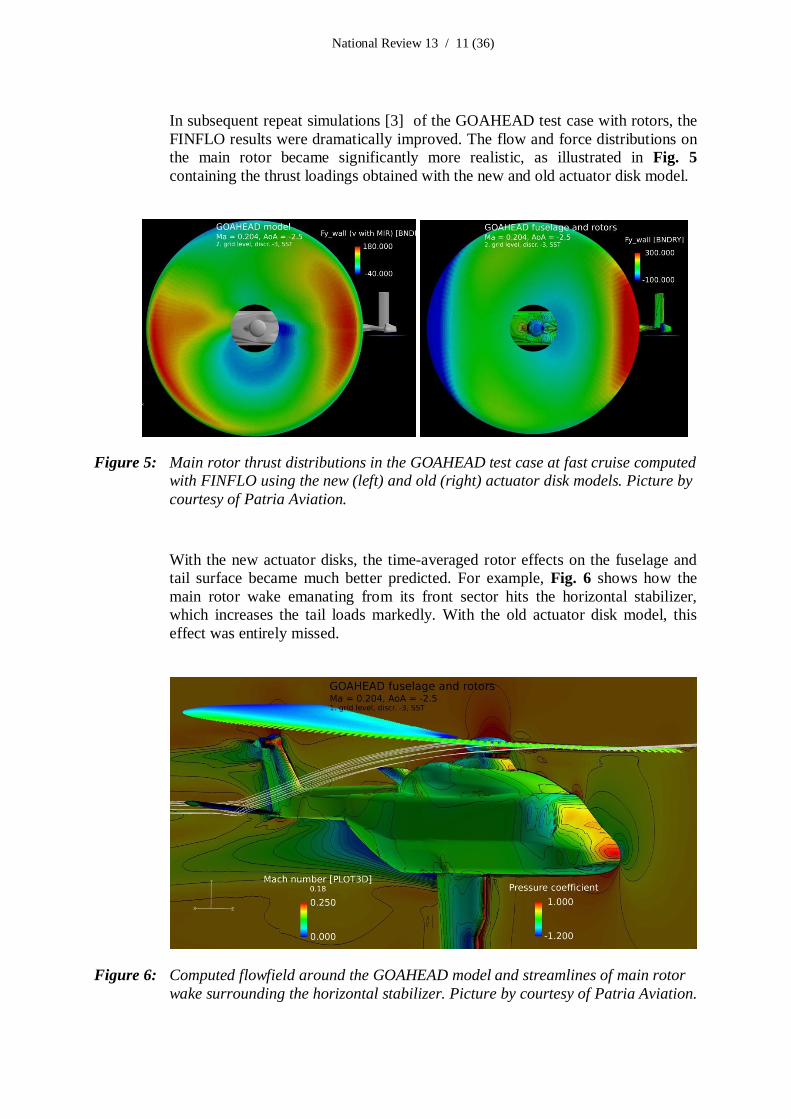
In subsequent repeat simulations [3] of the GOAHEAD test case with rotors, theFINFLO results were dramatically improved. The flow and force distributions onthe main rotor became significantly more realistic, as illustrated in Fig. 5containing the thrust loadings obtained with the new and old actuator disk model.
Figure 5: Main rotor thrust distributions in the GOAHEAD test case at fast cruise computedwith FINFLO using the new (left) and old (right) actuator disk models. Picture bycourtesy of Patria Aviation.
With the new actuator disks, the time-averaged rotor effects on the fuselage andtail surface became much better predicted. For example, Fig. 6 shows how themain rotor wake emanating from its front sector hits the horizontal stabilizer,which increases the tail loads markedly. With the old actuator disk model, thiseffect was entirely missed.
Figure 6: Computed flowfield around the GOAHEAD model and streamlines of main rotorwake surrounding the horizontal stabilizer. Picture by courtesy of Patria Aviation.
National Review 13 / 12 (36)
In addition to the single GOAHEAD test case, the new actuator disk model wastested with a simple detached rotor on a wide range of flow cases covering hover,extremely fast cruise, autorotation and even a vortex-ring state. Furthermore, themethod was successfully applied to aircraft propellers at high thrust settings and atidle. The results always appear quite realistic, and the modes of automatic bladeangle control for rotors and propellers respond quickly and correctly withoutoscillations. In the current state, time-averaged flow simulations for helicopterfuselages with actuator disks can be performed with improved confidence.
13.2.1.1.2 Computational Fluid Dynamics activities at Finflo Ltd.Computational fluid dynamics (CFD) research at Finflo Ltd. is based on the in-house flow solver FINFLO. An essential feature of the code is a Chimera methodapplied in simulating flow fields around the F-18C fighter. Basic features of themethod are described by [4]. Since then significant improvements have made inthe algorithm. The Chimera method currently utilizes accurate wall distances, arefined interpolation method and a completely new dominating criterion for theoverlapping grid blocks. The Chimera method is also applied for a prediction ofhelicopter rotor flow fields [5]. These simulations are time accurate andconsequently time consuming. An actuator disk provides means to compute therotor flow field as a steady-state solution. Several alternatives for the actuator diskmodel have been developed and the results compare fairly well with the time-accurate simulations.As a part of the FINAF Hornet Mid Life Upgrade 2 (MLU2) Program, unsteadyflow cases have been simulated using different approaches: URANS and DelayedDetached Eddy Simulation (DDES). The time-averaged loads predicted by thesemethods do not differ significantly from each other, but the DDES predictioncontains higher frequencies. As compared to the steady-state RANS predictionthere are significant differences in the time-accurate results. At a high angle ofattack the simulated flow field remains often oscillatory even in the RANSsimulation, but these oscillations are unphysical. An example of the simulatedflow fields is a pull-up case at Ma = 0.75, AoA = 9.4º and nz = 5.1 (Fig. 7).
Co-operation with CFSE and RUAG has been made for more than ten years.Meetings have been arranged to handle technical aspects and general CFDdevelopment, e.g. in Lausanne in July 2014. Recently the FINFLO and the NSMBcodes were evaluated by calculating two flow cases at a high angle of attack forthe F/A-18 [6].

National Review 13 / 13 (36)
Figure 7: An iso-surface of the kinetic energy of turbulence colored by the eddy viscosity ina pull-up case. Flight parameters are Ma = 0.75, AoA = 9.4 and nz = 5.1.Picture by courtesy of Finflo Ltd.
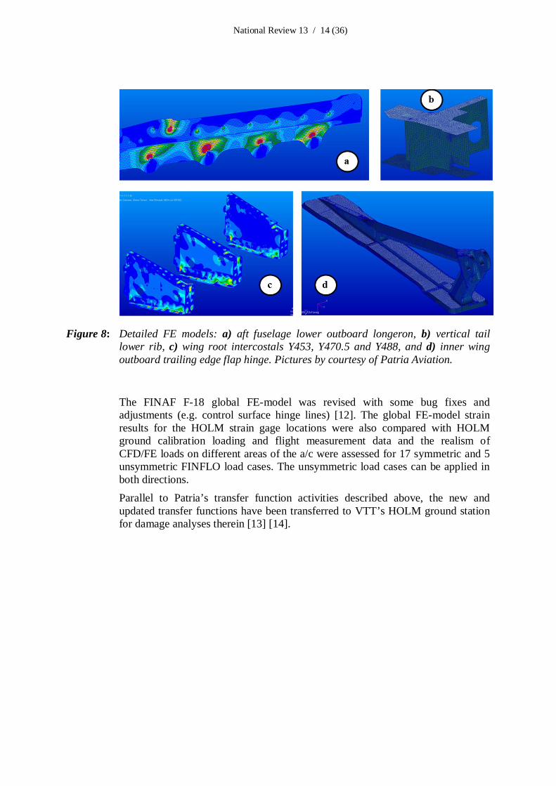
13.2.1.2 Hornet FE modeling – updatePrevious development phases of the global and detailed finite element (FE)modeling of the FINAF F-18C Hornet have been outlined in [1] Chapter 13.2.1.3.Since then some new detailed FE models have been prepared: aft fuselage loweroutboard longeron [7], vertical tail lower rib [8], wing root intercostals Y453,Y470.5 and Y488 [9], and inner wing outboard trailing edge flap hinge [10], Fig.8. According to these analyses, the aft fuselage lower outboard longeron is FullLife in the FINAF usage, but the other parts have some fatigue issues and requirepre-emptive repair actions. New analyses with previously prepared detailed FEmodels of vertical tail stub Y590.5 and bulkhead Y508 wing root shear tie wereperformed [11] to define transfer functions for life estimation based on straingauges installed in HOLM instrumentation modification, see reference [1]Chapter 13.2.2.1.2 and this report’s Chapter 13.2.2.1.1.
National Review 13 / 14 (36)
Figure 8: Detailed FE models: a) aft fuselage lower outboard longeron, b) vertical taillower rib, c) wing root intercostals Y453, Y470.5 and Y488, and d) inner wingoutboard trailing edge flap hinge. Pictures by courtesy of Patria Aviation.
The FINAF F-18 global FE-model was revised with some bug fixes andadjustments (e.g. control surface hinge lines) [12]. The global FE-model strainresults for the HOLM strain gage locations were also compared with HOLMground calibration loading and flight measurement data and the realism ofCFD/FE loads on different areas of the a/c were assessed for 17 symmetric and 5unsymmetric FINFLO load cases. The unsymmetric load cases can be applied inboth directions.Parallel to Patria’s transfer function activities described above, the new andupdated transfer functions have been transferred to VTT’s HOLM ground stationfor damage analyses therein [13] [14].
National Review 13 / 15 (36)
13.2.2 Fatigue tracking systems
13.2.2.1 FINAF F-18 HOLM jets in routine squadron servicePrevious research activities of the two FINAF F-18 HOLM (Hornet OperationalLoads Measurement program) jets can be found in [1] Chapter 13.2.2.1. Like theother Hornets, the two HOLM jets, with tail numbers HN 432 and HN 416, arerotated in the Satakunta, Lapland and Karelian Air Commands.The “production” version of the HOLM onboard system has collected statisticallyreliable flight data from FINAF’s routine fleet usage since 2006, and since thenFINAF squadrons have continuously delivered flight data to VTT for dataanalyses. To date VTT has analyzed 1817 flights, and reported 1554 flights in thesemi-annual fatigue tracking results reports [15]. However, following the 2013restructuring and associated budget cuts within the Finnish Defence Forces andthus within the FINAF as well, several analysis activities at VTT have beendiscontinued.Related to flight data analyses, VTT has studied continuous-time fatigue damageanalysis based on two methods, the stress life and strain life methods. Accordingto the studies, the continuous-time fatigue damage analyses give more accuratedamage histories, from which the cumulative damage can be observed in timedomain with respect to flight parameter and strain gage data [16].
The HOLM ground analysis environment has been updated to correspond to theHOLM modifications [17] [18] [19] (see next section).
In addition to the HOLM onboard measurement system modification (see nextsection) the ground analysis environment with its in-house developed programshas been updated.The HOLM fatigue analysis database has been updated [20] [21]. The databaseworks seamlessly with the data from the HOLM ground analysis environment. Inaddition to data from the fatigue tracking system the database includes all theneeded information from the data analysis process.The HN structural damage database has also been updated. The database has beenused e.g. in screening the fatigue critical structural locations of the FINAF F-18C/D configurations and to help focusing the proactive maintenance planningactivities. All observations emerged in the FISIF community (up to FISIF PMM2012 (05/2012)) have been added to the database. Additionally, the graphical userinterface GUI 4.0 has been updated. [22]As a part of the international F/A-18 cooperation the FINAF assigned VTT toprepare a HOLM data set i.e. the specific collection of measured data excludingthe analysis results to be supplied to the FISIF partners and to be used as they seefit. During this time frame two datasets were provided [23] [24] .

National Review 13 / 16 (36)
13.2.2.1.1 HOLM modificationThe FINAF has routinely been running the Hornet Operational LoadsMeasurement (HOLM) program since 2006. The goal in this program is toquantify the effects of operational usage by the FINAF on the structure of theF/A-18 aircraft and therefore to support the aircraft structural integritymanagement. The flying in the structurally challenging AOA-Q combinations (buffeting) is reflecting as increasing the number of external signs of fatigue onVertical Tail in the Finnish fleet and therefore makes this assembly as one of thecurrent hot spots of the aircraft. Another structurally interesting area is the Y508Former’s shear tie region which, in case of fatigue cracking, could lead to time-consuming (wings off) repair. There are doubts if buffeting would be the primefactor for driving the Y508 cracks also.
As a step to cope with the on-going structural issues the FINAF startedmodification process in which the existing HOLM instrumentation was extendedto support the national aircraft structural integrity management plan, Fig. 9. Themodification helps assessing the structural impact of new training missions. Inaddition to the HOLM system modifications, some of the current strain sensorswere relocated into a more acute (i.e. fatigue critical) structural locations.
Figure 9: An overview of the onboard HOLM system (the HOLM measurands) after theHOLM modification. Rectangular symbols denote the new strain gauge locationsand the colors indicate sampling rates. Picture by courtesy of VTT.
The existing on-board HOLM system for the two FINAF F/A-18 Hornets (HN-416 and HN-432) [1] Chapter 13.2.2.1 was modified to account for the increased
National Review 13 / 17 (36)
buffet-induced dynamic stressing of the FY508 and the vertical tail regions. Theexisting data acquisition system was upgraded and a total of 12 new channels (8strains + 4 accelerations) and associated LRU, system cable harnesses and otherneeded accessories were added and the systems were calibrated mechanically andelectrically to these two HOLM jets, Fig. 9. [25] [26] [27] [28] [29] [30]. The twoHOLM jets are slightly different in their instrumentation suite.
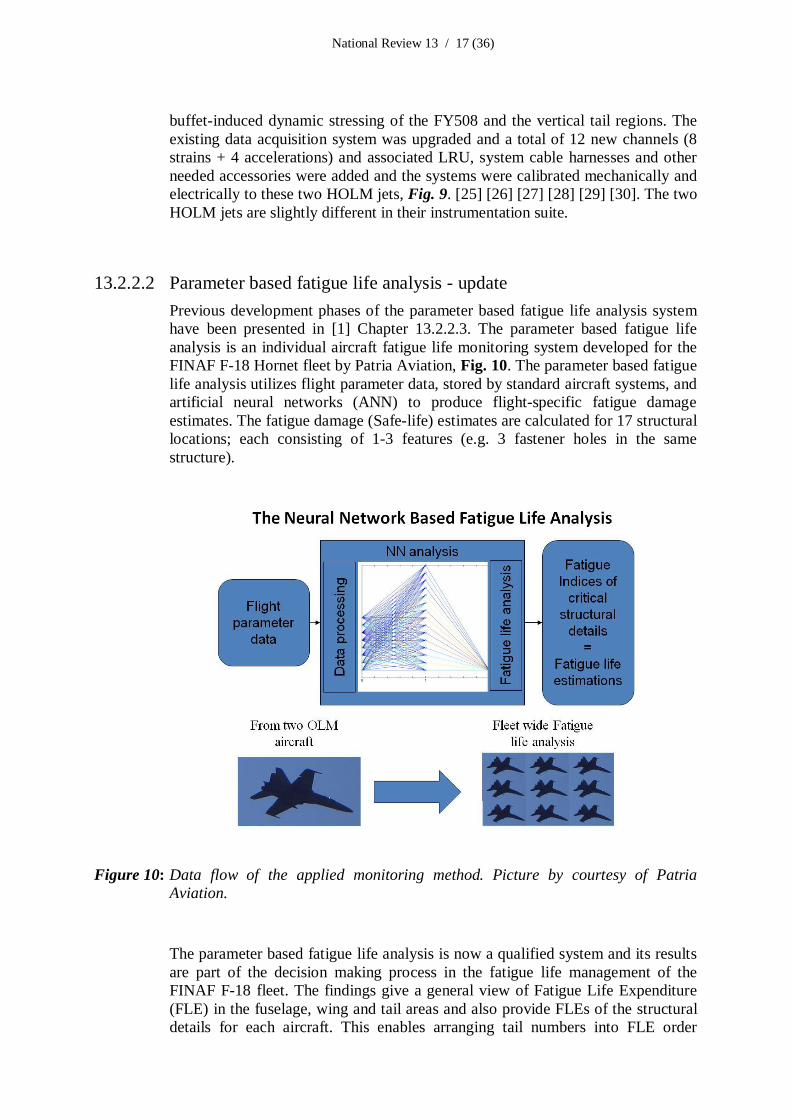
13.2.2.2 Parameter based fatigue life analysis - updatePrevious development phases of the parameter based fatigue life analysis systemhave been presented in [1] Chapter 13.2.2.3. The parameter based fatigue lifeanalysis is an individual aircraft fatigue life monitoring system developed for theFINAF F-18 Hornet fleet by Patria Aviation, Fig. 10. The parameter based fatiguelife analysis utilizes flight parameter data, stored by standard aircraft systems, andartificial neural networks (ANN) to produce flight-specific fatigue damageestimates. The fatigue damage (Safe-life) estimates are calculated for 17 structurallocations; each consisting of 1-3 features (e.g. 3 fastener holes in the samestructure).
Figure 10: Data flow of the applied monitoring method. Picture by courtesy of PatriaAviation.
The parameter based fatigue life analysis is now a qualified system and its resultsare part of the decision making process in the fatigue life management of theFINAF F-18 fleet. The findings give a general view of Fatigue Life Expenditure(FLE) in the fuselage, wing and tail areas and also provide FLEs of the structuraldetails for each aircraft. This enables arranging tail numbers into FLE order

National Review 13 / 18 (36)
(ascending/descending) for any structural location for scheduling repairs,inspections and structural part replacements. The FLE results for some criticallocations are still unreliable by absolute value due to problems in the transferfunction produced by FEM, but as the performance of the ANNs for all locationshave been verified to be of good quality, the FLE results for all locations areusable for relative comparisons between individual aircraft or for examining FLEtrends in function of time.
The technical background of the analysis is comprehensively explained in theICAF presentation at 2007 [31]. Previous development phases of the parameterbased fatigue life analysis system was presented in [1] Chapter 13.2.2.3. Apresentation of the current status, usage and experiences of the monitoring methodfor FINAF fleet management is found in the Symposium presentation [32].
13.2.2.2.1 Analysis developmentSince the ICAF 2013 [1] the analysis has been extended by adding the wing rootintercostal locations [Chapter 13.2.1.2] in the system. Two new HOLM straingages were needed for this and neural networks for them were trained andevaluated [33]. Then the individual aircraft fatigue tracking for these locationswas performed for the whole FINAF F-18 fleet flights for years 2000-2007(flights available for Patria at that time) [34].As the FINAF F-18 fleet go through structural repairs and modifications, thefatigue life analysis parameters may also change. For example some structuralpart could be replaced or its fatigue life expenditure is removed (removed initialcracks) or slowed down (reduced stress level). Future development is to defineindividual fatigue analysis parameters for each aircraft which take into accountlife improvement factors of the repairs.
13.2.2.2.2 In-service maintenancePrevious performance review of the system has been conducted two years agoconcerning years 2011-2012. Continuous performance assessment is also requiredin the future, because the operating environment is under constant change. Theneed for retraining of the ANN is decided on the grounds of the assessment.
13.2.2.2.3 Coverage of the analysesExtending the coverage of analyzed flights has been delayed but recently flightparameter data from the years 2008-2014 were received for analysis. Then almostfull service life of the FINAF’s F-18s will be covered. Also early flights from1995 to 1999 are planned to be analyzed in the near future. The coverage of thestructural locations is already extensive but new needs might always arise.

National Review 13 / 19 (36)
13.2.2.3 Research efforts towards an OLM replacement system (HawkUpgrade 2)
13.2.2.3.1 Structural health monitoring (SHM) – updatePrevious activities related to the fatigue tracking activities of the FINAF Hawkswere highlighted in previous ICAF reviews e.g. [1] Chapter 13.2.2.4, includingthe investigations related to the replacement of the Mk66’s obsolete ESDA(electronic structural data acquisition system) onboard monitoring system.Emmecon’s SHM system (strain measurement and analysis) has further beendeveloped since the previous review, Fig. 11. One FINAF Mk66 jet trainer wasequipped with Emmecon’s onboard SHM prototype system during the jet’snormal squadron service. During the three-month normal squadron service period(63 flights total) the SHM system collected in-flight data from two structurallocations (vertical fin and tailplane).
Figure 11: An overview of Emmecon’s SHM system. Picture by courtesy of Emmecon Ltd.
The onboard data acquisition, processing and storage of the prototype SHMsystem was functional as anticipated during the squadron service period. Post-flight analyses of the in-flight data however revealed two issues. First, the EMIprotection (protection against electromagnetic interferences) of the cabling of thevertical fin strain gauges was not adequate to shield the VHF signals emittingfrom the VHF antenna (located at the tip of the vertical fin) thus causingunwanted disturbances on the measurement signal. Second, the prototype SHM’soperating system was not stable in all situations, as the operating system was

National Review 13 / 20 (36)
observed to be vulnerable in events where the aircraft’s main powers are switchedoff.The above issues have been eliminated in the updated prototype SHM system.The goal is to install updated prototype SHM systems to a few Mk66 aircraft (2-3jets) during 2015 for new squadron flight trials.
13.2.2.3.2 Mk66 structural life and the mini OLM activities
To come up with the most potential fatigue critical structural details of theFINAF’s Mk66 jet trainer fleet and the associated integrity management plan, thefatigue critical structural details and the long experience in their rework activitiesfrom the older FINAF Mk 51/51A fleet were assessed. Estimates for the onset ofMk66 structural fatigue damage for the most important structural assemblies weremade by utilising the Mk 51/51A cracking observations, maintenance records, thecumulative flight syllabi data and the data from previous OLM programs [1]Chapter 3.4 and from the above Mk66 SHM experiences.
A decision has been made within the FINAF to instrument one Mk66 jet trainerwith a mini OLM system capable of collecting enough in-flight data fromdedicated test flights as well as from normal squadron service, to come up with anaverage spectrum for the most important structural assemblies. The aircraft isbeing instrumented at the writing of this review (Fig. 12) and the flights (tens offlights rather than hundreds of flights) will be flown during 2015.
Figure 12: An overview of Mk66 tailplane mini OLM instrumentation. Picture by courtesy ofVTT Ltd.

National Review 13 / 21 (36)
The fatigue damage estimates obtained, as described above, will be fine-tunedusing the average usage spectrum from the planned flights. Another use of theaverage usage spectrum is to come up with the structural integrity managementplan for the remaining service life of the FINAF Mk66 fleet. Yet another goalwith the use of the new in-flight data is to develop and teach the first prototypeneural network (NN) for the Mk66’s tail. After the mini OLM flights, theprototype NN will then be tuned using the in-flight data obtained from the dataobtained from the 2-3 SHM equipped Mk66 jets, as soon as statistically enoughflights with the onboard SHM systems have been flown.
13.2.3 Structural integrity of composite materials
13.2.3.1 Thermographic studies – updatePrevious activities have been reported in [1] Chapter 13.2.3.1. Penetrated water ormoisture ingress in the composite sandwich structures has caused problems inaircraft structures. Flight surfaces have been lost during the flights, becausemoisture corrodes the honeycomb and further reduces the strength of the adhesive.Water (moisture) can also cause additional defects during the composite repairs,which have resulted in the expansion of the moisture (in closed cavity), hencecausing skin blow core phenomena during the curing cycle (heating) of the repair.The number of penetrated water-induced failures is on the rise. Thus, penetratedwater in the composite structures operating in arctic conditions has been aresearch activity in Finland for several years.
VTT and Patria have been working in close co-operation to develop a method todetect moisture and efficiently remove it from the structures. More than 50rudders of the FINAF F/A-18 jets have been inspected during the period andwater has been detected from around 20 % of inspected rudders.
The procedure is divided to three phases:1. X-ray inspection, which can indicate suspected water in one or multiple
honeycombs.2. Drying procedure (several hours)
3. Thermographic inspection to verify remaining water.- If water is detected after thermographic inspection, the procedure
steps 2 and 3 are repeated as long as structure is found to be dry.X-ray inspection can detect assumed water ingress, if the water has filled most ofone or several honeycomb cells. The drawback is that there is no certainty, if theindication is from water or excess adhesive/resin from manufacturing process. Ifdoubt of water ingress is observed during X-ray inspection, structure will gothrough special drying procedure.
A gentle procedure to remove the water is applied to the honeycomb compositestructure, because it is essential not to cause skin blow core effect during thedrying phase. Honeycomb composite structure is heated under a low vacuum tovaporize moisture from the structure. The heating takes place for several hours.

National Review 13 / 22 (36)
Thermographic inspection based on the phase transition of water exploits thephase transition energy that is needed for the ingressed water to be defrosted(melted). Water ingress indication is observed in a specific phase transitiontemperature and the indication insures the presence of water. Another advantageof this method is that no additional excitation source is needed for the tests.Method based on the phase transition can be especially exploited during the longperiod of arctic weather conditions in Finland and other cold areas. Compositestructures can be left outside in freezing conditions overnight and inspected whenthey have been brought in to warm conditions. The non-contact thermographicinspections are conducted during the warm-up period in the hangar, Fig. 13.
Figure 13: An example of the thermographic inspection based on the phase transition ofwater. Abnormal warming is observed within the circled area (left). Themeasurement locations are displayed with symbols ”X” (right); each warm-upcurve’s color is related to the same color ”X” (lower right within the circledarea). Moisture ingress/penetrated water can be observed from the curvesdenoted with “MOISTURE”. Picture by courtesy of VTT.
This thermographic inspection method has shown to be the only method thatdetects small amounts of penetrated water from large areas without removingaircraft composite parts from the aircraft – and the only method within the FINAFwhich can detect small amounts of water. The costs of thermography inspection +drying are far less than the costs of repair planning + repair, not to mention thecosts of new rudders.
13.2.3.2 Fracture mechanics based analysis and tests of delaminationsPrevious fracture mechanics-based studies on composite structures werehighlighted in [1] Chapter 13.2.3.2. The work on numerical fracture mechanicsusing virtual crack closure technique (VCCT) has been continued and it isdescribed below. The work concentrated on the applicability of VCCT on analysisof ductile adhesive joints. The software tool used in the work was ABAQUS.Analysis work was supported by experimental tests in mode I loading.

National Review 13 / 23 (36)
The fracture mechanics based analysis work on adhesively bonded joints wascontinued in mode II loading. A test specimen was designed to be used in endnotched flexure (ENF) test in three point bending [35]. The purpose was to designa specimen with stable crack growth and without the excessive frictional effectdue to loading of the specimen. The specimen consists of aluminum adherendsand FM 300-2 film adhesive. Preliminary simulations show that a stable crackpropagation of approximately 5 mm is possible to obtain with careful selection ofadherend thickness and initial crack size. Therefore it is possible to obtain alsopropagation values for the adhesive in mode II loading. Typically the crackpropagation is unstable in the ENF test and only insert values are obtained.Based on the work performed on VCCT analysis two publications are prepared.The previously reported work on analysis of the FINAF F-18 trailing edge flapdelaminations is published as a poster presentation in ICAF 2015 [36]. Thesecond paper with the title ‘Applicability of VCCT in Model I Loading ofYielding Adhesive Bonded Joint – a Case Study’ is submitted for publication inInternational Journal of Adhesion and Adhesives [37]. The paper is under peerreview process. In addition, a paper including simulations performed on wedgetest specimens is under preparation. The simulation of wedge test is illustrated inFig. 14.
Figure 14: Simulation of the wedge test specimen). Picture by courtesy of Aalto University.
The experimental work in mode I loading was continued. The double cantileveredbeam (DCB) with aluminum adherends and FM 300-2 adhesive film was used.The tests are performed on specimens with either two or one adhesive film layer.On the average the propagation GI values are similar for both cases but in case ofone adhesive film the bridging effect of the carrier is more significant. In additionthe behavior of the crack in the beginning is different as illustrated in Fig. 15.

National Review 13 / 24 (36)
Figure 15: Fracture energy of DCB specimens with two (above) or one (below) adhesivelayers. Picture by courtesy of Aalto University.
13.2.4 Structural integrity of metallic materials
Previous surface renewal activities have been reported in [1] Chapter 13.2.4. Thefollowing summarizes the research efforts since the previous review.
13.2.4.1 Verification of repair methods (JoBolt)The influence of repair methods and fastener types for fatigue behaviour werestudied using test coupons manufactured of aluminium. Patria Aviation Oydesigned, manufactured and planned the tests and administered the test program.The coupon tests were designed to complement earlier fatigue tests [1] [38] [39]

National Review 13 / 25 (36)
[40] [41] [42] [43] of the FINAF F-18 repair methods. The coupon fatigue testswere performed by VTT. Three different coupon types were utilised: a basicdogbone coupon (7050-T7451), a lap joint coupon (7075-T76) and a double-lapcoupon (7075-T76), Fig. 16. A total of 52 + 24 + 25 coupons were tested (basicdogbone, lap joint and double-lap, respectively).
Figure 16: An overview of the three coupon types. Picture by courtesy of Patria Aviation Oyand VTT.
With the lap joint and double-lap joint coupons with Jo-Bolt fasteners the aim wasto emulate a region within the FINAF F-18 Hornet’s Inner Wing Front Spar (holes#170 - #173 modification). Further, the Interference Fit Hi-Loks were planned tobe replaced using Cold Worked holes and oversized Jo-Bolt fasteners (NAS1671-3L-5 for the lap joints and NAS1671-3L-8 for the double-lap joints), whosefatigue characteristics were not adequately known prior to the planned tests.According to the HSB 63511-02 (Handbuch Strukturberechnung) the blind (non-driven) rivets such as Jo-Bolts are known to have very low fatigue life (10 % - 25%) compared to the Hi-Loks, and no data on the effect of Cold Work wereavailable prior to the tests.
The dogbone specimen tests were performed to get information on how deepdents and blended/polished dents affect to the shot peened structures’ fatigue life.Before 8/2013 there was no ability in Patria to repair shot peened areas correctlyusing the flap peening or shot peening; landing gear parts were shot peened andsurface treated by Finnair engine repair shop (now part of GA Telesis). NowPatria has also the flap peen and manual shot peening capabilities, aimed at thepeening of e.g. Y488 Bulkhead/Match Angle chafing and the HT Bootstrap andthe nicks and gouges therein. A summary of the fatigue tests performed isprovided in Tables 1-2.

National Review 13 / 26 (36)
Table 1: Summary of the fatigue test performed, dogbone coupons. Table by courtesy ofPatria Aviation Oy.
Series ID SP(1) W/O
SP
AD(2) PC(3) P(4) CA(5) Smax(6)
[MPa]
Smax(6)
[MPa]
Smax(6)
[MPa]
VA(7) # ofcoupons
YHN0012390-1 360 320 250 12
YHN0012390-2 360 320 250 12
YHN0012390-3 360 320 250 12
YHN0012390-4 3
YHN0012390-5 3
YHN0012390-6 3
YHN0012390-7 3
YHN0012390-8 3
Table remarks:1SP = Shot peening (performed prior to tests)2AD = Artificial damage (produced before the tests): a dent mark (approx. 0.5 mm depth) punctured usinga pyramid tip of 2.5 mm width3PC = Pre-cycling4P = Polish: The ratio of polish area radius and the artificial damage depth about 10, surface roughness0.4 – 0.6 m (Ra)5CA = Constant amplitude loading (R = -0.3)6Smax = maximum stress [MPa], there were 4 coupons per maximum stress level in the CA tests7VA = Variable amplitude loading (see Fig. 17 for spectrum details)
Table 2: Summary of the fatigue test performed, lap and double-lap coupons. Table bycourtesy of Patria Aviation Oy.
Series ID Lapjoint
Double-lap joint
W/OC/W(3)
C/W(4) Maximum applied gross section stress Smax[MPa] / # of coupons per stress level
# ofcoupons
YHN0012400(1) 110 / 4 90 / 4 70 / 4 12
YHN0012410(1) 110 / 4 90 / 4 70 / 4 12
YHN0012420(2) 130 / 4 110 / 4 90 / 4 70 / 1 13
YHN0012430(2) 170 / 4 150 / 4 130 / 4 12
Table remarks:1Jo-Bolt fastener NAS1671-3L-5 (cold working according to PS 19180)2Jo-Bolt fastener NAS1671-3L-8 (cold working according to PS 19180)3W/O C/W = Without cold working4Cold working applied
The specimens were subjected to either constant amplitude or variable amplitudeloading, Fig. 17.

National Review 13 / 27 (36)
Figure 17: An overview of the variable amplitude loading spectrum for the dogbonecoupons: HOLM S47 (Y488 BLKHD). Picture by courtesy of Patria Aviation Oy.
For the dogbone coupons the following observations could be made (Fig. 18):- The fatigue life of the dogbone coupons with shot peening and sharp dents
was surprisingly good in that the dents appear to affect less than the Kttheory. In fact, the fatigue life was better than basic material Al 7050-T7451 without shot peening (MIL-HDBK-5H values).
- The achieved shot peening LIF (life improvement factor) was 4 … 10depending on the stress level. Sharp edge removal from the coupons priorto the tests was noticed to be important.
- Blending and polishing inside the shot peened area is a bad solution(fatigue life was lower than without dent removal). Repair shot peening isrequired.
- During the dent removal process, the Confidence Cut is mandatory

National Review 13 / 28 (36)
Figure 18: Summary of the dogbone coupons’ results (constant amplitude loading), naturallogarithm fitting in the test results. Picture by courtesy of Patria Aviation Oy.
For the Jo-Bolt tests (lap and double-lap coupons) the following observationscould be made (Fig. 19):
- CW (cold worked) Jo-Bolt joint seems to be as good as the I/F(interference) fit Hi-Lok (tested earlier). Confirmation for the Inner WingFront Spar modification, it can be done twice: the first oversize before 0.4FLE and the second oversize at 0.8 FLE (for exceeding latter limit)
- The cold worked LIF (life improvement factor) for the Jo-Bolt joint isapprox. 1.3 (single lap joint) and approx. 2 (double lap joint).
- In the single lap joint coupons the secondary bending effect is dominant.The fatigue life of the Jo-Bolt joint is barely as good as the Hi-Lok joint(single lap joint, Class 2 holes).
- The HSB 63511-02 blind rivet “LIF” of 0.1 … 0.25 can be neglected forJo-Bolt joints. The HSB “LIF” is valid for CherryMax-type blind rivets.

National Review 13 / 29 (36)
Figure 19: Summary of the lap coupon and double-lap coupon results (constant amplitudeloading), natural logarithm fitting in the test results. Picture by courtesy ofPatria Aviation Oy.
All in all, the artificial dents were relatively deep (30 % stress increase) whichmay not be typical for small fleet blends, therefore the blend/polish may workbetter in reality than in these tests. More different joint specimen tests, based onthe needs specified by planned future repairs, are being planned for the dentremoval (manual shot peening repairs/manual flap peening repairs) includingassociated confidence cut studies [44] [45].
13.2.4.2 FISIF Hole Salvage projectUnder the auspices of the FISIF, a collaborative coupon testing program wasconducted. As per the Canadian plan, the open-hole coupons were etched (byAustralia), then pre-cycled (by Switzerland), after which the specimens wereshipped to Patria, Finland, where the coupons’ hole was first reamed (oversized),then cold worked (split sleeve) followed by interference fit or clearance fitfastener installation in order to have the coupons represent in-service usage. Patriathen provided the coupons to VTT who conducted spectrum fatigue tests on thecoupons and investigated the fracture surface characteristics using quantitativefractography on coupons with a hole with either clearance fit or interference fit.Detailed analysis has been done [46].
National Review 13 / 30 (36)
13.2.5 Repair technologies
13.2.5.1 Repair technologies for the FINAF F-18 metallic primary structures
13.2.5.1.1 DIARC plasma coating for reliable and durable structural bonding of metals –update
Previous metal bonding activities, specifically those related to DIARC plasmacoatings, have been reported earlier in [1] Chapter 13.2.5.2.1. More recentachievements are outlined below.Grit blast silane and AC-130 sol-gel treatments were tested to assess theirperformance in aluminum, titanium and stainless steel structural epoxy bonding.Static single lap shear and static double lap shear specimens were tested as dryand wet at room temperature. Wedge tests were performed in a hot and wetexposure and in hot fresh water and salt water immersions. Acceptable field levelmethods were found for unclad and clad 7075 aluminum bonding without primers.With titanium and stainless steel, the use of BR 6747-1 primer was found to benecessary for durable adhesion. In a case study, AC-130 sol-gel without a primeron naval grade 5083 aluminum provided good results also when immersed inBaltic Sea water. Due to copyright restrictions, further in-depth information of thestudy and the results can be found in [47].
13.2.5.1.2 An experimental study on the fatigue performance of CFRP and BFRP repairedaluminum plates
Cracked aluminum plates were repaired with multidirectional carbon/epoxy andboron/epoxy reinforcements. Aircraft repair conditions were simulated by using asteel bonding rig that constrained the effective thermal expansion to the levelmeasured from real locally heated aircraft structures. Residual thermal stresseswere varied using the rig and by varying the curing and testing temperatures. Therepairs were tested using a variable amplitude loading (R = -0.14) with anti-buckling edge supports. The residual thermal stresses had a rectilinear and distincteffect on the crack growth rate. The structural support against bending had asignificant effect on the fatigue life of the repairs. The fatigue life improvementfactor with the center-cracked single-sided repairs was greatest with the wet-laminated carbon/epoxy repairs having a stiffness ratio of 1.04. With edge-cracked specimens the longest life was achieved with the double-sidedboron/epoxy repairs having a stiffness ratio of 0.65. The cracked aluminum plate2024-T3 clad had the longest fatigue life, followed by the S07-1020 and 7075-T6clad aluminum grades. Due to copyright restrictions, further in-depth informationof the study and the results can be found in [48].

National Review 13 / 31 (36)
13.3 Related activities
13.3.1 Environmentally friendly corrosion protection studies
As reported earlier in [1] Chapter 13.3.1, the joint European EDA ECOCOATproject (European Defense Agency, Environmentally Compliant Coatings inAeronautic) was successfully completed. Sol-gel based inorganic-organic hybridcoatings were developed and coated on aeronautical parts including cadmiumplated steel with two aims: To protect the cadmium-plating against the corrosioninitiated especially by runway de-icing chemicals, and targeting the hybridcoating to provide alternative coating solutions for cadmium plating as well ashexavalent chromium conversion coatings.Since then and during the current reporting period, Finnish efforts within Patriahave continued. The three-fold aim at Patria is to a) tailor the hybrid coating to beapplied to certain FINAF F/A-18 landing gear components such that b) the hybridcoating could be painted and finally c) obtain the airworthiness approval to thenew coating.
13.3.2 EDA PATCHBOND
The PATCHBOND project (duration 4 years, started in November 2014) dealswith bolt-free damage repairs of composite primary aircraft structures. The jointEuropean Ad Hoc Research & Technology Project PATCHBOND is beingconducted under the auspices of EDA (European Defence Agency in theframework of EDA R&T Category B projects).Repair of damaged fixed and rotary wing platforms is a considerable matter for allEuropean countries. Damage repairs of primary composite structures arecommonly performed by the application of bolted plates. This method introducesadditional damage to the structure especially for composite structures where thereinforcement fibres are cut by the drilling of the bolt holes. In some cases boltedrepairs are not possible, for instance in the case of damaged sandwich structures.Thus, complex (bolted) alternatives may have to be developed to restore the loadpath.
A better repair method is the application of adhesive bonded composite patchesinstead of bolted plates. This method is already used for secondary structures butis not accepted by the airworthiness authorities for the repair of primarystructures. Therefore boltless repair methods for primary composite structureshave to be developed that are compliant with the airworthiness requirements. Theproject covers the whole range from damage assessment, numerical analysis,repair design procedures, materials and processes, inspection, structural healthmonitoring and quality control, up to certification aspects.
Several European research partners take part in the project, alphabetically: Finland(Aalto University, Patria Aviation Oy, VTT Ltd.), Germany (WIWeB, AirbusDefence and Space), the Netherlands (NLR, KVE Composites Repair, FokkerServices B.V.), Norway (FFI, NDLO, DolphiTech, FiReCo, Light Structures) andSpain (INTA).

National Review 13 / 32 (36)
13.3.3 Thermal spray activities to restore structural integrity ofsubsystem components
As there are several on-aircraft parts and subsystem components (e.g. hydraulics,flight controls etc.) that wear out during normal service, the FINAF initiated astudy with VTT to investigate possibilities to develop in-country capabilitiesrelated to restoring the structural integrity of the worn parts thus supportingmaintenance, repair and overhaul (MRO) activities and improving themanagement and sustainment of spares and component life cycle. One suchsubsystem component wearing out in normal service is the FINAF F-18 Aileron’shydraulic cylinder’s flange, Fig. 20.
Figure 20: An overview of the Aileron’s hydraulic cylinder’s worn flange. Picture bycourtesy of the FINAF.
Thermal spraying is a process of particulate deposition in which the molten, semi-molten or solid particles are deposited on to substrate. The coating microstructureresults from the deposition of the particles on the coated surface. The particlepowder for the thermal spray coatings was selected, acquired and then sieved toachieve better particle size distribution for the thermal spray activities. Testspecimens of the Aileron’s hydraulic cylinder flange material were prepared, ontowhich several thermal spray surface coating methods were applied (one thermalspray per specimen). Five thermal spray methods were investigated:
- Arc Spray (twin wire arc spray)- HVAF (High Velocity Air Fuel)- HVOF DJ (High Velocity Oxygen Fuel, “Diamond Jet”)- HVOF CJS (High Velocity Oxygen Fuel, “Carbide Jet Spray”)- SPD (Supersonic Particle Deposition)
The sprayed specimens were then subjected to test to evaluate microstructure,hardness, Young’s modulus, wear (abrasion) as well as cohesion and adhesioncharacteristics for each of the 5 thermal spray methods. The work is on-going.

National Review 13 / 33 (36)
Once the research and associated analysis efforts are completed, the chosen“winner” thermal spray method will be applied to spray the actual Aileron’shydraulic cylinder hinge and subsequently to investigate the optimal machiningprocedures to obtain the desired dimensions. The goal is to transfer the developedrepair capability from an applied research facility to an in-country industrialentity.

National Review 13 / 34 (36)
13.4 References
[1] ICAF. 2013. A Review of Aeronautical Fatigue Investigations in Finland during thePeriod April 2011 - February 2013. (A. Siljander, Ed.). ICAF Doc 2428 (VTTResearch Report VTT-R-02105-13). VTT: Espoo.
[2] Hoffren, J. 2014. Evaluation of capability to perform flow simulations for helicopterfuselages. Report NH-S-0023. Tampere: Patria Aviation, Finland (in Finnish).
[3] Hoffren, J. 2015. Renewal of actuator disk model for helicopter rotors. Report NH-S-0026. Tampere: Patria Aviation, Finland (in Finnish).
[4] Siikonen, T., Rautaheimo P., & Salminen, E. 2000. Numerical techniques for compexaeronautical flows. Proceedings of the ECCOMAS 2000 Conference, Vol. 5, 2000.
[5] Ilkko, J., Hoffren J., & Siikonen, T. 2011. Simulation of a helicopter rotor flow.Journal of Structural Mechanics, 44, pp. 186-205.
[6] Guillaume, M., Gehri, A., Stefanie, P., Vos, J., Siikonen, T., Salminen, E., &Mandanis, G. 2012. Swiss/Finland Computational Fluid Dynamics Simulation onthe F/A-18. The 28th International Congress of the Aeronautical Sciences, Brisbane,Australia, Sept. 23-28, 2012, 2012.
[7] Liius, M. 2013. Detailed FE-Model of F-18 Hornet Lower Outboard Longeron.Report HN-L-0230. Tampere: Patria Aviation Oy (classified).
[8] Lähteenmäki, J. 2013. F-18 Hornet's Vertical Tail's Lower Rib's (54.25% - 62.5%)Detailed FE Model. Report HN-L-0231. Tampere: Patria Aviation Oy (classified,in Finnish).
[9] Liius, M. 2014a. F-18 Hornet's Inner Wing Root's Intercostals (Y453.000, Y470.500and Y488.000) Detailed FE Model. Report HN-L-0237. Tampere: Patria AviationOy (classified, in Finnish).
[10] Liius, M. 2014b. F-18 Hornet's Inner Wing Outboard Trailing Edge Flap Hinge'sDetailed FE Model. Report HN-L-0247. Tampere: Patria Aviation Oy (classified,in Finnish).
[11] Liius, M. 2014c. F-18 Hornet's Vertical Tail Stub Y590.5 and Bulkhead Y508 WingRoot Shear Tie: Fatigue critical areas' transfer functions to SGs S73a, S75a, S76and S77. Report HN-L-0242. Tampere: Patria Aviation Oy (classified, in Finnish).
[12] Malmi, S. 2014a. F-18 Global FE Model (rev. B), Loads and MechanicalCalibration Assessments. Report HN-L-0232. Tampere: Patria Aviation Oy(classified, in Finnish).
[13] Laakso, R. 2015 [In preparation]. The damage analysis locations 5 within VTT'sHOLM ground station. VTT Research Report VTT-R-06112-14 (in Finnish).Espoo: VTT Technical Research Center of Finland.
[14] Öström, J., Janhunen, H., & Laakso, R. 2014 [Update, in preparation]. HOLM datastructure development v5.0. VTT Report VTT-M-05828-14. Espoo: VTTTechnical Research Center of Finland (in Finnish, classified).
[15] Laakso, R., Viitanen, T., & Merinen, S. 2013. F-18 Hornet: Fatigue Tracking Resultsof the Aircraft HN-416 and HN432 Using VTT's Ground Station - Semi-AnnualReport (VII/2012). Report VTT-R-07233-12 / 28.1.2013. Espoo: VTT TechnicalResearch Center of Finland (in Finnish, classified).
[16] Laakso, R. 2013a. Continuous-time fatigue damage analysis based on stress lifemethod. VTT Research Report VTT-R-05907-11. Espoo: VTT Technical ResearchCenter of Finland (in Finnish, classified).

National Review 13 / 35 (36)
[17] Laakso, R. 2013b. Testing sequence 11/2013. Report VTT-M-08617-13. Espoo:VTT Technical Research Center of Finland (in Finnish, classified).
[18] Laakso, R. 2013c. Level Counter 12/2013. Report VTT-M-08618-13. Espoo: VTTTechnical Research Center of Finland.
[19] Laakso, R. Testing sequence 10/2014. Report VTT-M-04869-14. Espoo: VTTTechnical Research Center of Finland (in Finnish, classified).
[20] Viitanen, T., Laakso, R., Janhunen, H., & Merinen, S. 2014. HOLM fatigue analysisdatabase, HOLM_BASE v4.0.0. VTT Research Report VTT-R-08929-13. Espoo:VTT Technical Research Center of Finland (in Finnish, classified).
[21] Laakso, R. 2014. HOLM-analysis instructions v3.0. Report VTT-M-01912-14.Espoo: VTT Technical Research Center of Finland (internal use).
[22] Janhunen, H. 2013. The F/A-18 fatigue cracks database v4.0: Part number specificfatigue cracking observations. VTT Research Report VTT-R-01983-13. Espoo:VTT Technical Research Center of Finland (in Finnish, classified).
[23] Viitanen, T., & Janhunen, H. 2013. FINAF data package 2. (22.11.2013). Espoo:VTT. 11 p. (Memorandum VTT-M-07999-13, in Finnish, classified).
[24] Viitanen, T., & Janhunen, H. 2014. FINAF data package 3. (31.3.2014). Espoo:VTT. 11 p. (Memorandum VTT-M-01538-14, in Finnish, classified).
[25] Liukkonen, S. 2013a. HOLM MOD 1: HN-416 Additional Stain Gauge Installations.VTT Research Report VTT-R-02315-13. Espoo: VTT Technical Research Centerof Finland (in Finnish, classified).
[26] Liukkonen, S. 2013b. HOLM MOD 1: HN-416 Mechanical Calibration of the FY508Shear Tie. VTT Research Report VTT-R-02317-13. Espoo: VTT TechnicalResearch Center of Finland (in Finnish, classified).
[27] Liukkonen, S. 2013c. HN-416 Onboard HOLM System's Electrical Calibration. VTTResearch Report VTT-R-07126-13. Espoo: VTT Technical Research Center ofFinland (in Finnish, classified).
[28] Viitanen, T. 2014a. HOLM MOD 1: HN-432 Additional Stain Gauge Installations.VTT Research Report VTT-R-04358-14. Espoo: VTT Technical Research Centerof Finland (in Finnish, classified).
[29] Liukkonen, S. 2014. HOLM MOD 1: HN-432 Mechanical Calibration of the FY508Shear Tie. VTT Research Report VTT-R-02538-14. Espoo: VTT TechnicalResearch Center of Finland (in Finnish, classified).
[30] Viitanen, T. 2014. HN-432 Onboard HOLM System's Electrical Calibration 2014.VTT Research Report VTT-R-04700-14. Espoo: VTT Technical Research Centerof Finland (in Finnish, classified).
[31] Tikka, J. & Salonen, T. 2007. Parameter Based Fatigue Life Analysis of F18Aircraft. Durability and Damage Tolerance of Aircraft Structures: Metals vs.Composites.
[32] Tikka, J. & Salonen, T. 2015. Practical Experience of Neural Network BasedFatigue Life Monitoring.
[33] Malmi, S. 2014b. Training Procedures and Analysis Capability. Report HN-S-0062D. Tampere: Patria Aviation Oy (classified).
[34] Malmi, S. 2014c. F-18 Hornet, Parametric-Based Fatigue Tracking, Annual Report2009. Report HN-L-1536B. Patria Aviation Oy (classified, in Finnish).
[35] Jokinen, J. 2013. Mode II Test of Adhesive Joints. Aalto University, School of

National Review 13 / 36 (36)
Engineering, Department of Applied Mechanics. Report KRT-T391 (in Finnish).[36] Jokinen, J., Wallin, M., & Saarela, O. 2015a. Delamination Analysis of Trailing Edge
Flap. The 28th ICAF Symposium, Helsinki, 3-5 June 2015.[37] Jokinen, J., Wallin, M., & Saarela, O. 2015b. Applicability of VCCT in Mode I
Loading of Yielding Adhesively Bonded Joints - a Case Study. International Journalof Adhesion and Adhesives, p. 13.
[38] ICAF. 2001. A Review of Aeronautical Fatigue Investigations in Finland untilMarch 2001. Research Report BVAL33-011139/AOS. (A. Siljander Ed.). Espoo:VTT Manufacturing Technology, Maritime and Mechanical Engineering. June 2001.
[39] ICAF. 2003. A Review of Aeronautical Fatigue Investigations in Finland during thePeriod February 2001 to March 2003. Research Report BTUO33-031123. (A.Siljander Ed.). Espoo: VTT Industrial Systems, Product Performance. April 29, 2003.
[40] ICAF. 2005. A Review of Aeronautical Fatigue Investigations in Finland During thePeriod April 2003 to April 2005. Research Report BTUO33-051366 (A. SiljanderEd.). Espoo: VTT Industrial Systems. June 2, 2005.
[41] ICAF. 2007. A Review of Aeronautical Fatigue Investigations in Finland During thePeriod May 2005 to April 2007. (A. Siljander, Ed.) ICAF document 2410 (VTTResearch Report VTT-R-03406-07). Espoo: VTT Industrial Systems. April 25,2007.
[42] ICAF. 2009. A Review of Aeronautical Fatigue Investigations in Finland during thePeriod May 2007 to April 2009. (A. Siljander Ed.). ICAF Document 2418 (VTTResearch Report VTT-R-02540-09). Espoo: VTT Industrial Systems. April 14,2009.
[43] ICAF. 2011. A Review of Aeronautical Fatigue Investigations in Finland during thePeriod May 2009 - March 2011. (A. Siljander Ed.). ICAF Document 2427 (VTTResearch Report VTT-R-02827-11). Espoo: VTT. April 12, 2011.
[44] Koski, K., Laakso, R., & Juntunen, J. 2014a. Fatigue tests for test coupons made ofaluminum alloys. VTT Research Report VTT-R-05810-13 (in Finnish). Espoo:VTT Technical Research Center of Finland.
[45] Koski, K., Laakso, R., Linna, J., & Keinonen, M. 2014b. Verification of RepairMethods: Fatigue Tests. (Lecture presented by Linna, J.) LentotekniikanRakennetutkimuksen Neuvottelupäivät XIII, Tampere 27.-28.8.2014, Halli.
[46] Koski, K., Siljander, A., & Salonen, J. 2013. FISIF Collaborative coupon program –crack growth rates. VTT Research Report VTT-R-04389-13 (17.6.2013). Espoo:VTT (confidential).
[47] Aakkula, J., & Saarela, O. 2014a. Silane based field level surface treatment methodsfor aluminium, titanium and steel bonding. International Journal of Adhesion &Adhesives, 48, pp. 268-279. Elsevier 2013 Ltd. All rights reserved.
[48] Aakkula, J., & Saarela, O. 2014b. An experimental study on the fatigue performanceof CFRP and BFRP repaired aluminium plates. Composite Structures, 118, pp. 589-599. Elsevier 2014 Ltd. All rights reserved.

National Review 13 / 37 (36)
Report’s title
A REVIEW OF AERONAUTICAL FATIGUE INVESTIGATIONS IN FINLANDMARCH 2013 – FEBRUARY 2015Customer, contact person, address
Finnish Defence Force Logistics Command, Joint System CentreAir Systems DivisionMr. Ari KivistöP. O. Box 69; FI-33541 Tampere; FinlandProject name105295 – ICAF 2015 KoontiraporttiEditors Pages
Aslak Siljander, Piritta Varis 36/
Keywords Report identification code
Aeronautical fatigue, military aircraft, fixed wing, research project,structural integrity, Finland
ICAF Doc 2432 / 24.4.2015(VTT- VTT-CR-01811-15/ 18.5.2015)
Summary
This document was prepared for the delivery to the 34th Conference of the International Committee onAeronautical Fatigue and Structural Integrity scheduled to be held in Helsinki, Finland on 1-2 June 2015.A review is given of the aircraft structural fatigue research and associated activities which form part of theprograms within the Finnish Defence Force Logistics Command Joint Systems Centre (FINLOGCOM JSC) AirSystems Division; Patria Aviation Oy; VTT Technical Research Centre of Finland Ltd. (VTT); Aalto University(Aalto); Finflo Ltd. and Emmecon Ltd.The review summarizes fatigue related research programs and investigations on specific military fixed wingaircraft since the previous Finnish National Review (tabled in the 33rd Conference, ICAF, Jerusalem, Israel) up toFebruary 2015.
Confidentiality PublicEspoo 21.5.2015Approved by
Aslak Siljander Piritta VarisICAF National Delegate / Finland (VTT) Research Scientist (VTT)
Editors’ contact addressVTT, P. O. Box 1000, FI-02044 VTT, Finland (Street: Vuorimiehentie 3, Espoo, Finland)Distribution
Unclassified. Distribution unlimited. This document has been authorized by the FINLOGCOM JSC for unlimitedpublic release [Permission BL7208 / 20.5.2015].