a reference model, design approach, and time system ...passino/rcsweb/reference... · a reference...
TRANSCRIPT
A Reference Model, Design Approach, andDevelopment Illustration toward Hierarchical Real-Time System Control for Coal Mining Operations
Hui-Min HuangRichard QuinteroJames S. Albus
Robot Systems DivisionNational Institute of Standards and Technology
Gaithersburg, Maryland 20899
CONTENTS
ABBREVIATIONS.....................................................................................................................11. INTRODUCTION..................................................................................................................12. A GENERIC REFERENCE MODEL.......................................................................................4
2.1 The Definition of Machine Intelligence.........................................................................42.2 An Intelligent Machine Unit.......................................................................................62.3 The Task Decomposition Function..............................................................................62.4 The World Modeling Function and the Underlying Database..............................................72.5 The Sensory Processing Function................................................................................82.6 The Value Judgement Function...................................................................................102.7 The Information Flow Model......................................................................................102.8 Level of Abstraction for Machine Intelligence Units........................................................112.9 Hardware.................................................................................................................152.10 Human Interaction...................................................................................................15
2.10.1 Operator Interface.....................................................................................152.10.2 Design Considerations and Workload Analysis for Human
Interaction Devices........................................................................................163. The RCS Task Decomposition Methodology...............................................................................17
3.1 Establish the Context................................................................................................183.1.1 Define the System Objectives and the Problem Scope.......................................183.1.2 Describe the Approach Selected to Achieve the System Goals.............................19
3.2 Develop an Organizational Hierarchy............................................................................193.2.1 Autonomy and Modularity...........................................................................203.2.2 Hierarchical Levels and Their Pre-Defined Functional Requirements.....................203.2.3 System Goals............................................................................................203.2.4 Operation Requirements and Functional Coherence...........................................213.2.5 Concurrent Computing Timing Requirements and Software Module Size..............213.2.6 Existing Facilities and Resources..................................................................213.2.7 The Coal Mining Environment.....................................................................223.2.8 Other constraints........................................................................................223.2.9 Contradictions...........................................................................................22
3.3 Perform task analysis................................................................................................223.3.1 Spatial Coordination Strategy.......................................................................233.3.2 Real-Time Planning vs. Predefined Script Planning..........................................243.3.3 Emergency Reaction Capability and Level of Intelligence..................................243.3.4 Coordinate Reference Frames, Map Resolutions and Level of Abstraction.............243.3.5 Task Command Complexity for Different Levels.............................................253.3.6 Existing Constraints, Existing Practices, and Flexibility...................................26
3.4 Develop RCS plans..................................................................................................273.4.1 The Description Language
State Transition Diagrams........................................................................273.4.2 RCS Plan.................................................................................................283.4.3 Plan Frame...............................................................................................29
4. METHODOLOGY APPLICATIONTHE CONTEXT DEFINITION AND THE HIERARCHY
DEVELOPMENT.....................................................................................................294.1 General Problem Definition and the Developed Hierarchy.................................................294.2 The Context for the Vehicle Guidance Controller............................................................30
4.2.1 Scope for Vehicle Guidance..........................................................................304.2.2 Scenarios for Vehicle Guidance.....................................................................31
5. METHODOLOGY APPLICATION

TASK ANALYSIS.........................................................................................................325.1 General Coordinate Frame Transition............................................................................325.2 Path Coordinate Frame..............................................................................................335.3 Vehicle Guidance Analysis.........................................................................................33
5.3.1 Problems Affecting Vehicle Guidance............................................................345.3.2 Vehicle Guidance Error Control....................................................................35
5.4 The Integration of BOM/NET Commands.....................................................................385.5 Level 1 -- Actuator Level...........................................................................................395.6 Level 2 -- Primitive Level..........................................................................................40
5.6.1 Tram Motion Control Module......................................................................405.6.2 Boom Control Module................................................................................435.6.3 Stabilizer Control Module...........................................................................445.6.4 Gathering Head Control Module....................................................................445.6.5 Conveyor Control Module...........................................................................45
5.7 Level 3 -- E-Move Level............................................................................................465.7.1 Initialization.............................................................................................465.7.2 Guidance Control Module............................................................................475.7.3 Coal Cutting Control Module......................................................................485.7.4 Coal Removal Control Module.....................................................................495.7.5 Support Control Module.............................................................................51
5.8 Level 4 -- Equipment Level........................................................................................515.9 Level 5 -- Section Control Level.................................................................................535.10 Level 6 -- Production Control Level...........................................................................565.11 The Resulting Task Tree..........................................................................................56
6. METHODOLOGY APPLICATIONTHE RCS PLANS..........................................................................................................576.1 A Production Level Plan............................................................................................576.2 Section Level Plans..................................................................................................596.3 Equipment Level Plans..............................................................................................616.4 E-move Level Plans..................................................................................................636.5 Primitive Level Plans................................................................................................65
7. DISCUSSION ON THE IMPLEMENTATION OF OPERATOR CONTROLINTERFACE LEVELS..........................................................................................................71
8. COMPUTER PROGRAM DESIGN AND IMPLEMENTATION...................................................739. SUMMARY.........................................................................................................................73ACKNOWLEDGEMENTS...........................................................................................................74REFERENCES..........................................................................................................................75Appendix A
OVERVIEW OF UNDERGROUND COAL MINING ENVIRONMENT..................................79Appendix B
THE JOY 14CM CONTINUOUS MINER..........................................................................81
1
ABBREVIATIONS
Coal Interface Detection CIDContinuous Miner (Continuous Mining Machine) CMElementary Move E-MoveExecutor EXJob Assignment Module JAIntelligent Machine System IMSIntelligent Machine Unit IMUMobile Control Structure MCSNational Institute of Standards and Technology NISTPlanner PLReal-Time Control System RCSSensory Processing SPState Transition Diagram STDTask Decomposition TDWorld Modeling WMU. S. Bureau of Mines BOMU. S. Bureau of Mines Testbed and Communication Network BOM/NET

1
A Reference Model, Design Approach, andDevelopment Illustration toward Hierarchical Real-
Time System Control for Coal Mining Operations1
Hui-Min HuangRichard Quintero
James S. Albus
Robot Systems DivisionManufacturing Engineering Laboratory
National Institute of Standards and TechnologyGaithersburg, Maryland 20899
1. INTRODUCTION
Coal, the nation's primary domestic energy resource, accounts for over 50% of the
total domestic electric power generation [Sc 89]2. The availability and the cost of coal
are vital to U. S. economic competitiveness. Coal mine safety is one of the key factors
affecting the cost of coal production. The objective of safety improvement is therefore a
primary motivation for conducting research in the area of computer-assisted coal mining
methods.
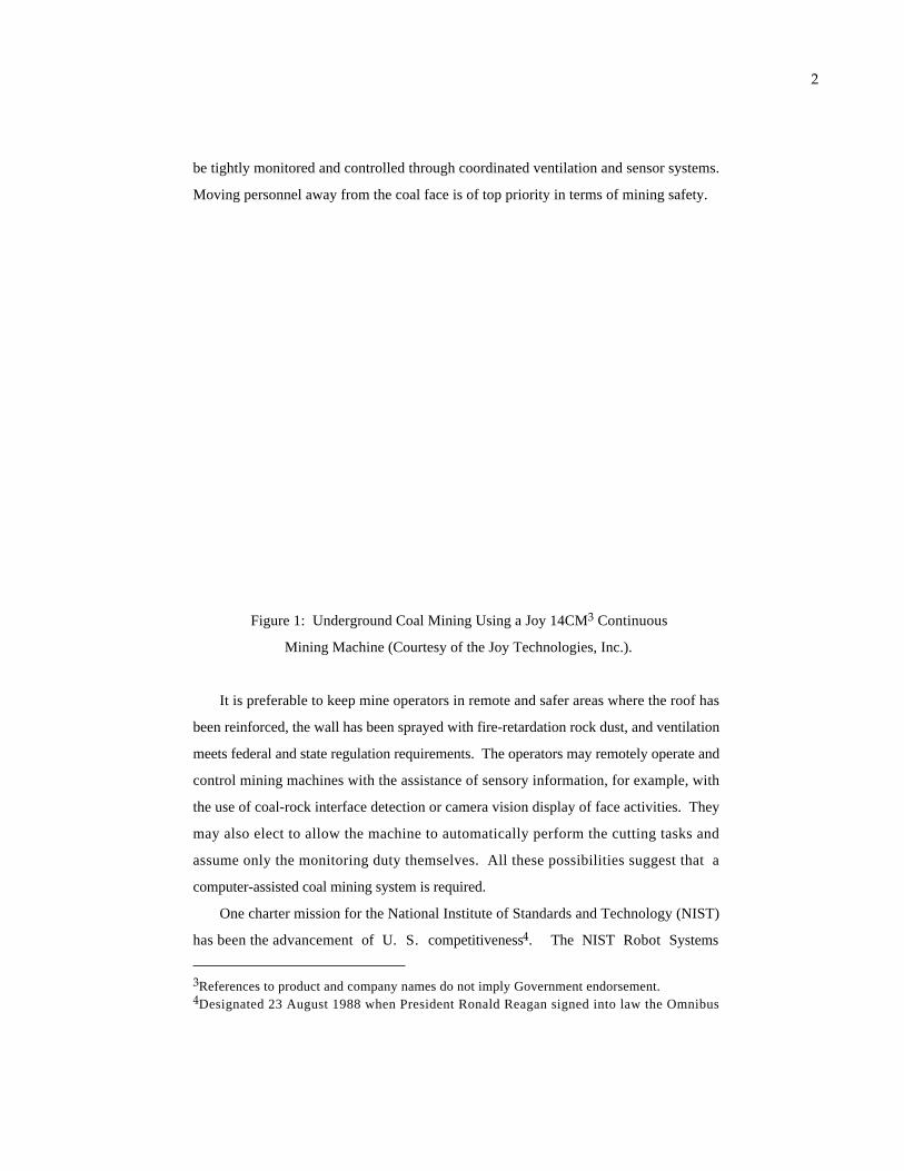
In the underground coal mining environment (figure 1), one of the most hazardous
areas is in the vicinity of the coal face (where the coal extraction operation takes place).
A major hazard is the potential for roof falls, especially with unsupported roofs.
Methane, which is very combustible, is hazardous due to the heavy usage of high-
voltage equipment (up to 9600 volts) and various electrical/electronic devices. Methane
is also lethal when inhaled in sufficient concentration. Methane content in the air must
1This work is sponsored by the U. S. Bureau of Mines under Interagency Agreement(J0189027).2Denotes the references listed at the REFERENCES section of this chapter.
2
be tightly monitored and controlled through coordinated ventilation and sensor systems.
Moving personnel away from the coal face is of top priority in terms of mining safety.
Figure 1: Underground Coal Mining Using a Joy 14CM3 Continuous
Mining Machine (Courtesy of the Joy Technologies, Inc.).
It is preferable to keep mine operators in remote and safer areas where the roof has
been reinforced, the wall has been sprayed with fire-retardation rock dust, and ventilation
meets federal and state regulation requirements. The operators may remotely operate and
control mining machines with the assistance of sensory information, for example, with
the use of coal-rock interface detection or camera vision display of face activities. They
may also elect to allow the machine to automatically perform the cutting tasks and
assume only the monitoring duty themselves. All these possibilities suggest that a
computer-assisted coal mining system is required.
One charter mission for the National Institute of Standards and Technology (NIST)
has been the advancement of U. S. competitiveness4. The NIST Robot Systems
3References to product and company names do not imply Government endorsement.4Designated 23 August 1988 when President Ronald Reagan signed into law the Omnibus

3
Division has been researching and developing a generic Real-time Control System
(RCS) hierarchical architecture [Ba 84] over the last decade and has been applying RCS
to various large-scale real-time control problems. The first RCS application concerned
laboratory robotics [Ba 79]. Later RCS applications include the NIST Automated
Manufacturing Research Facility (AMRF) [Si 83], the NASA Flight Telerobot Servicer
(FTS) [Al 87], and the Defense Advanced Research Projects Agency (DARPA)/NIST
Multiple Autonomous Undersea Vehicle (MAUV) [Al 88]. The current RCS projects
include a federally-funded Initiative for Intelligent Machine Systems, a submarine
automation demonstration project funded by DARPA, and the Air Force Next Generation
Controller (NGC) project.
The underground coal mining operation system control problem that the Robot
Systems Division is investigating under the sponsorship of the U. S. Bureau of Mines
is an ideal application for RCS. This chapter summarizes our first effort (1988 through
1990) in utilizing RCS as a reference model for the construction of a hierarchical coal
mining real-time control system. The primary objective of this effort is to establish the
reference model and to describe the design method. Coal mining is a very complex
operation which typically involves equipment, personnel, and process plants distributed
across hundreds of miles. This makes full implementation of a computer-assisted
mining system a very large undertaking. The NIST contribution to this problem is
focused on the development of a system design methodology. Such a methodology will
facilitate incremental implementation and integration, leading to an integrated coal
mining control system.
An overview of the mining environment, along with term definitions and a brief
description of the U. S. Bureau of Mines (BOM) testbed, are presented (in appendices A
and B, respectively) for those who are not familiar with them. A description of RCS as
a reference model in dealing with complex real-time system control problems is given.
Research on the application procedures for the reference models has been undertaken.
Preliminary research results are described in this chapter as the task decomposition
methodology. The application of this methodology is illustrated (sections 4 through 8).
The emphasis of the illustration has been put on a Joy 14CM continuous mining
Trade and Competitiveness Act and thereon renamed the National Bureau of Standards toNational Institute of Standards and Technology.
4
machine [Jo 82], as this is in line with the current research focus of the United States
Bureau of Mines, as described in [Sc 89].
2 . A GENERIC REFERENCE MODEL
The NIST Real-time Control System (RCS) architecture has been proposed as a
reference model for the real-time control of coal mining operations [Al 89]. RCS can be
viewed as an intelligent machine system (IMS) capable of reasoning and judging through
the interaction with its sensory systems and in turn driving its actuator systems to
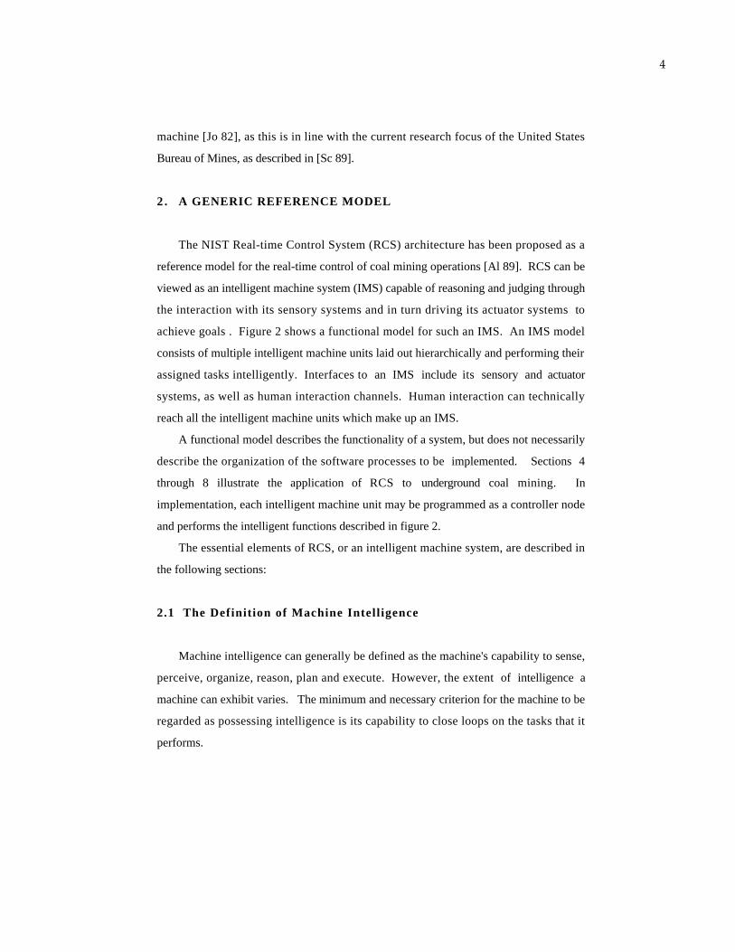
achieve goals . Figure 2 shows a functional model for such an IMS. An IMS model
consists of multiple intelligent machine units laid out hierarchically and performing their
assigned tasks intelligently. Interfaces to an IMS include its sensory and actuator
systems, as well as human interaction channels. Human interaction can technically
reach all the intelligent machine units which make up an IMS.
A functional model describes the functionality of a system, but does not necessarily
describe the organization of the software processes to be implemented. Sections 4
through 8 illustrate the application of RCS to underground coal mining. In
implementation, each intelligent machine unit may be programmed as a controller node
and performs the intelligent functions described in figure 2.
The essential elements of RCS, or an intelligent machine system, are described in
the following sections:
2.1 The Definition of Machine Intelligence
Machine intelligence can generally be defined as the machine's capability to sense,
perceive, organize, reason, plan and execute. However, the extent of intelligence a
machine can exhibit varies. The minimum and necessary criterion for the machine to be
regarded as possessing intelligence is its capability to close loops on the tasks that it
performs.
5
ENVIRONMENT
SYSTEM LEVEL INTELLIGENCE
PLAN
EVALUATION
PLAN
PREDICTEDINPUT
UPDATES
STATES
PLA
NR
ESU
LT
SSITU
AT
ION
EV
AL
UA
TIO
N
PERCEIVED
SITUATIO
N
VALUEJUDGMENT
SCORE,
JUDGE,
GROUP COORDINATION
KINEMATIC BEHAVIOR
DYNAMIC BEHAVIOR
ACTUATOR BEHAVIOR
HMH 6/91
EQUIPMENT INTELLIGENCE
TASKDECOMPOSE
PLAN,
COORDINATE,
SERVO,
SENSORYPROCESSING:
INTEGRATE,
DETECT,
RECOGNIZE,
EVENTS ACTIONS
KNOWLEDGE BASE
WORLDMODEL
UPDATE,
PREDICT,
An Intelligent Machine Unit
Figure 2: A Functional Model of an Intelligent Machine System
Legend:
Boundary for the Intelligent Machine System (IMS)
An Intelligent Machine Unit (IMU) in an IMS
A Functional Element in an IMU
SENSORS ACTUATORS
Hum
an
Inte
ract
ion
A Functional Element in an IMU that Provides Interface to the IMS
2.2 An Intelligent Machine Unit

6
An intelligent machine system consists of multiple intelligent machine units (IMU)
organized hierarchically. Each unit is a self-contained entity performing assigned tasks
through sensory interaction. An intelligent machine unit performs certain intelligent
functions, namely sensory processing, world modeling, and value judgement (as
described in sections 2.3 through 2.6) in its designated level of abstraction (section 2.8).
All the units coordinate and communicate cohesively in a predefined model to achieve
system goals.
2.3 The Task Decomposition Function
The RCS task decomposition (TD) function, as can be seen in figure 3, is
responsible for planning and executing the decomposition of goals and/or tasks at each
level of the system's hierarchy. Task decomposition involves both a temporal
decomposition (into sequential actions along the time line) and a spatial decomposition
(into concurrent actions by different subsystems). Therefore, it is sufficient to describe a
task decomposition between any two successive levels as: the higher level sends down
"what needs to be done," and the lower level generates "how it can be done." A brief
description of the TD module is given below, whereas a more comprehensive discussion
of the subject can be seen in [Al 89] and [Hu 90-1].
For the input task commands, the job assignment manager (JA) is responsible for
selecting a proper execution command and partitioning the selected command into
necessary spatially or logically distinct jobs to be performed by the corresponding
physically distinct planners/executors.
Planning typically requires the evaluation of alternative hypothetical sequences of
planned subtasks. The planner hypothesizes some action or series of actions. The world
model predicts the results of the action(s). The value judgement module then determines
the value of some evaluation function on the predicted resulting state of the world. The
hypothetical sequence of actions producing the best value is then selected as the plan to
be executed by the executor. State transition diagrams can be used to describe RCS
plans.

7
PL3
PL2
PL1
Task
Planning
Execution
JA
Subtasks
Figure 3: The Task Decomposition Function in a RCS Architecture
JA: Job Assignment Manager
PlannersPL:
ExecutorsEX: EX1
EX2
EX3
Time
Space
Level ofAbstraction
In general, an executor (EX) is responsible for successfully executing the plans
prepared by the planners. The executor operates by selecting a subtask from the current
queue of planned subtasks and outputting a subcommand to the appropriate subordinate
IMU. The EX module monitors its feedback input in order to servo its output to the
desired goal of the subtask activity.
Executor output also contains requests for information from the world model module
and status reports to the next higher level in the TD module hierarchy.
2.4 The World Modeling Function and the Underlying Database
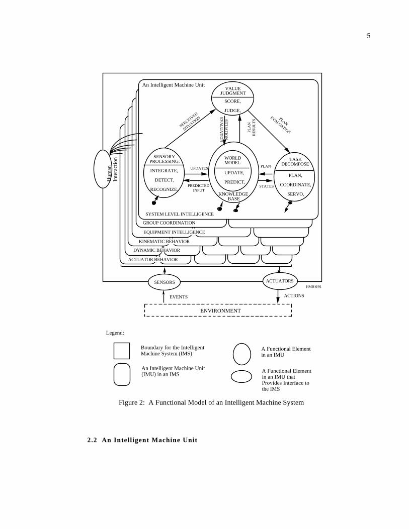
The major world model (WM) functions are to remember, estimate, and predict (see
figure 4). The WM functional modules at various levels perform the following
functions:
(a) Maintain the knowledge base, including the system's best estimated current
state, possible future states, maps, lists of objects and events, and attributes of objects
and events, and update it. The knowledge base is updated based on correlations and
8
differences between model predictions and sensory observations (see figure 4). Such a
knowledge base may be maintained as a distributed database.
WM
Recognized/Integrated
Events
SensoryObservations
Time
Updates
ModelPredictions
Space
SP
Figure 4: The World Model Function
Estimated Features
TD
Knowledge Base Command Execution
Time
Space
Tasks
StatesPredicts
VG
Reads
Commands
What is /What if
Computes
(b) Provide predictions of expected sensory input to the corresponding sensory
processing (SP) modules based on the state of the task and estimates of the external
world.
(c) Answer "What is?" questions asked by the planners and executors in the
corresponding level TD modules. The task executor requests information about the state
of the world and uses the answers to monitor and servo the tasks.
(d) Answer "What if?" questions asked by the planners in the corresponding level
TD modules. The WM modules predict the results of hypothesized actions.
2.5 The Sensory Processing Function
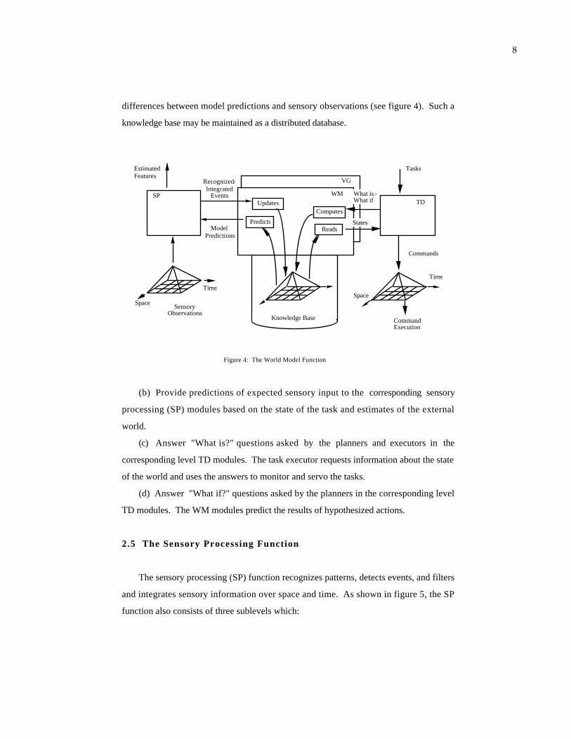
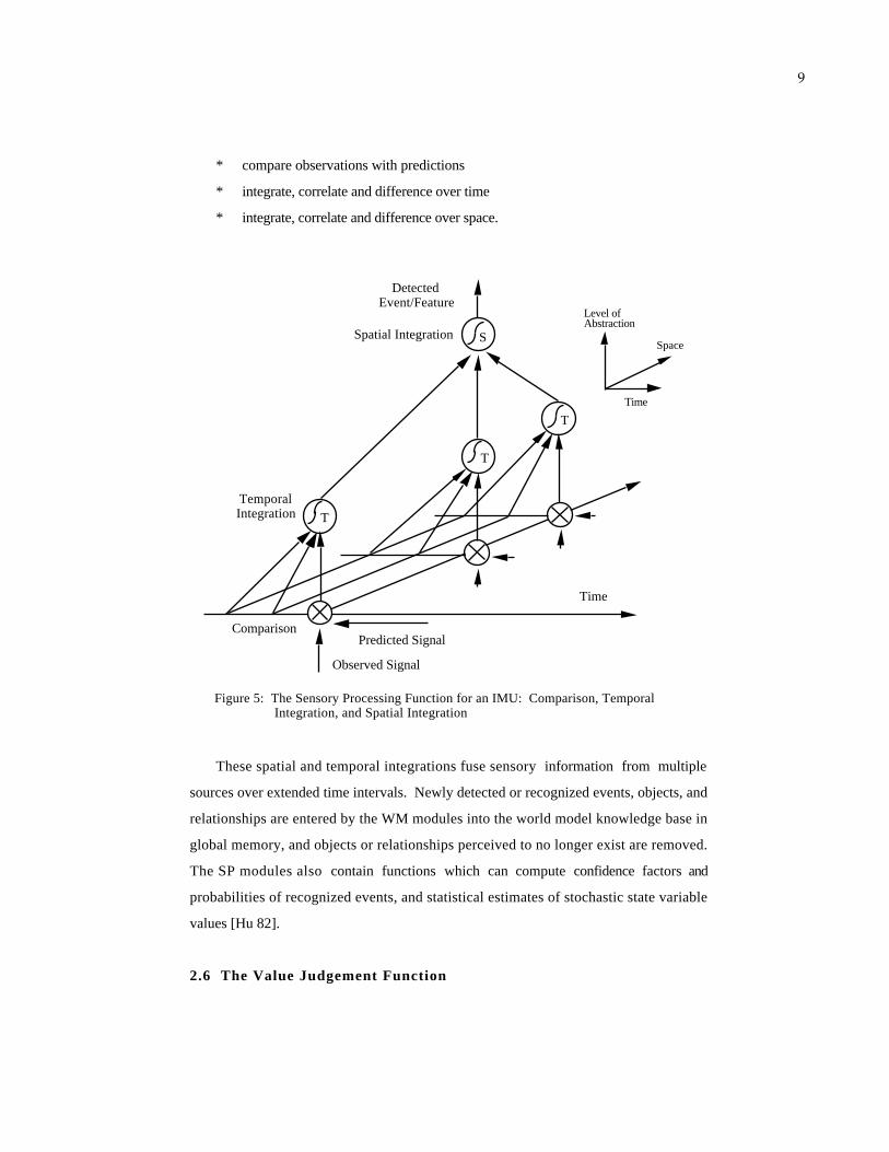
The sensory processing (SP) function recognizes patterns, detects events, and filters
and integrates sensory information over space and time. As shown in figure 5, the SP
function also consists of three sublevels which:
9
* compare observations with predictions
* integrate, correlate and difference over time
* integrate, correlate and difference over space.
T
S
T
T
Detected Event/Feature
Spatial Integration
TemporalIntegration
Time
Predicted Signal
Observed Signal
Comparison
Figure 5: The Sensory Processing Function for an IMU: Comparison, Temporal Integration, and Spatial Integration
Time
Space
Level ofAbstraction
These spatial and temporal integrations fuse sensory information from multiple
sources over extended time intervals. Newly detected or recognized events, objects, and
relationships are entered by the WM modules into the world model knowledge base in
global memory, and objects or relationships perceived to no longer exist are removed.
The SP modules also contain functions which can compute confidence factors and
probabilities of recognized events, and statistical estimates of stochastic state variable
values [Hu 82].
2.6 The Value Judgement Function

10
The value judgement function evaluates the current situation and potential future
consequences of hypothesized actions by applying evaluation functions to current states
and to future states expected to result from hypothesized actions. The evaluation
functions define a set of values over the state-space defined by state variables (typically
globally defined). These evaluation functions can be used to compute priorities, cost-
benefit values, risk estimates, and pay-off values of states of the world. Thus, working
together with the world model, the planners are able to search the space of possible
futures and choose the sequence of planned actions that produce the best value of the
evaluation functions. The executors are able to apply value judgments to moment-by-
moment behavioral decisions.
2.7 The Information Flow Model
The information flow model across intelligent units is illustrated in figure 6.
Sensory Data from Sensors/Subordinates
Status Reports from Subordinates
Sensory Data to Superior
Status Report to Superior
Commands From Superior
Commands to Subordinates
Operator Input/Output
Global Data Retrieval and Updates
An Intelligent Machine Unit
Figure 6: The Interface Model for an Intelligent Machine Unit
11
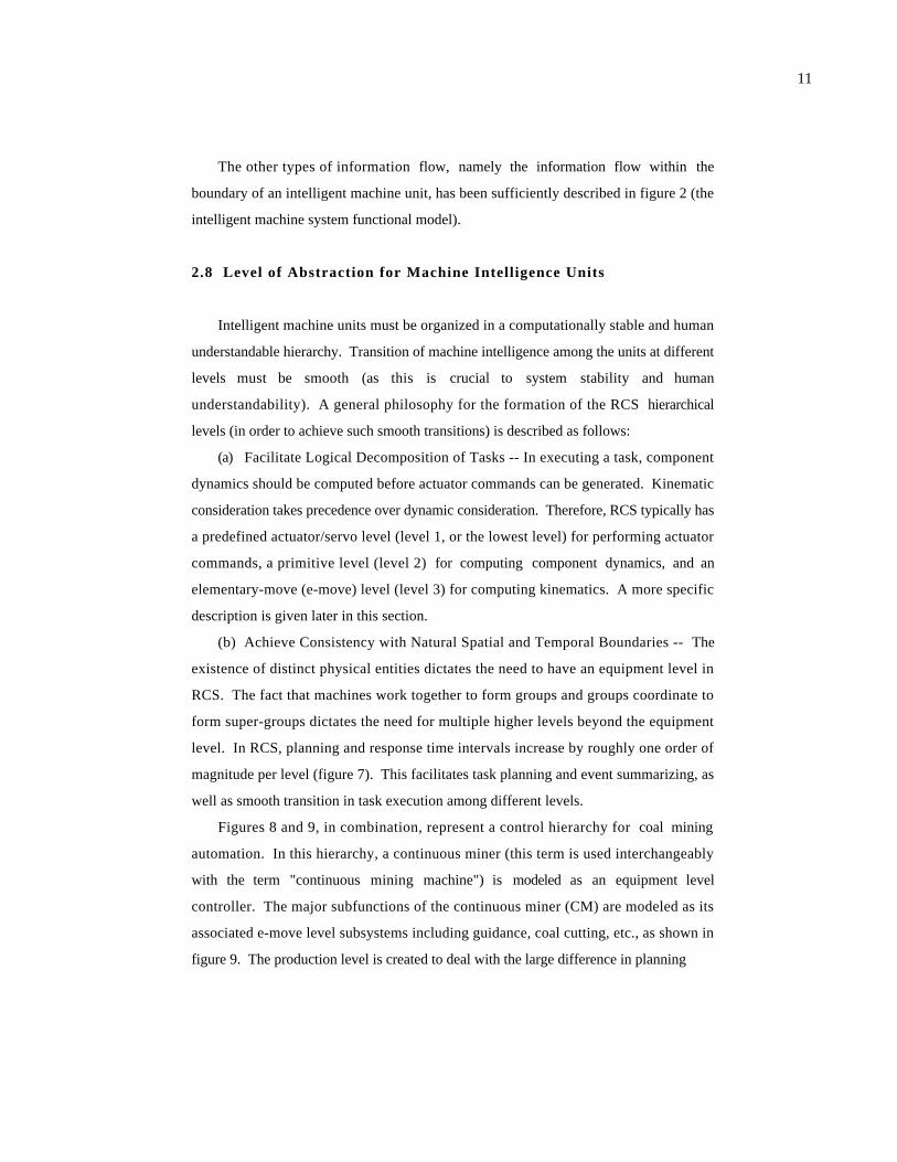
The other types of information flow, namely the information flow within the
boundary of an intelligent machine unit, has been sufficiently described in figure 2 (the
intelligent machine system functional model).
2.8 Level of Abstraction for Machine Intelligence Units
Intelligent machine units must be organized in a computationally stable and human
understandable hierarchy. Transition of machine intelligence among the units at different
levels must be smooth (as this is crucial to system stability and human
understandability). A general philosophy for the formation of the RCS hierarchical
levels (in order to achieve such smooth transitions) is described as follows:
(a) Facilitate Logical Decomposition of Tasks -- In executing a task, component
dynamics should be computed before actuator commands can be generated. Kinematic
consideration takes precedence over dynamic consideration. Therefore, RCS typically has
a predefined actuator/servo level (level 1, or the lowest level) for performing actuator
commands, a primitive level (level 2) for computing component dynamics, and an
elementary-move (e-move) level (level 3) for computing kinematics. A more specific
description is given later in this section.
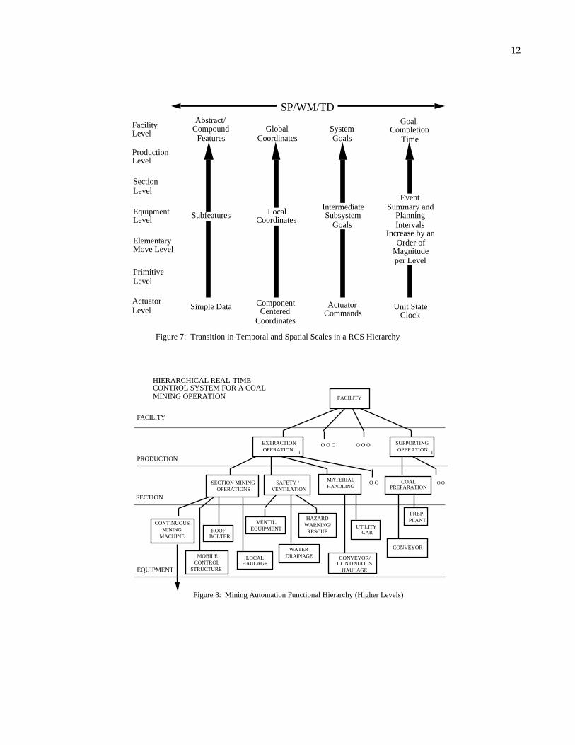
(b) Achieve Consistency with Natural Spatial and Temporal Boundaries -- The
existence of distinct physical entities dictates the need to have an equipment level in
RCS. The fact that machines work together to form groups and groups coordinate to
form super-groups dictates the need for multiple higher levels beyond the equipment
level. In RCS, planning and response time intervals increase by roughly one order of
magnitude per level (figure 7). This facilitates task planning and event summarizing, as
well as smooth transition in task execution among different levels.
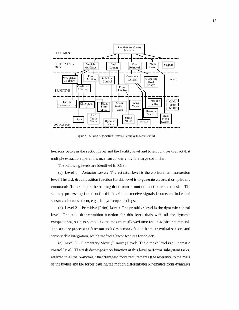
Figures 8 and 9, in combination, represent a control hierarchy for coal mining
automation. In this hierarchy, a continuous miner (this term is used interchangeably
with the term "continuous mining machine") is modeled as an equipment level
controller. The major subfunctions of the continuous miner (CM) are modeled as its
associated e-move level subsystems including guidance, coal cutting, etc., as shown in
figure 9. The production level is created to deal with the large difference in planning
12
Facility Level
Production Level
Section Level
Equipment Level
Elementary Move Level
Primitive Level
Actuator Level
Abstract/Compound
FeaturesGlobal
CoordinatesSystem Goals
Subfeatures Local Coordinates
Intermediate Subsystem
Goals
Simple Data Component Centered
Coordinates
Actuator Commands
Goal Completion
Time
Event Summary and
Planning Intervals
Increase by an Order of
Magnitudeper Level
Unit State Clock
SP/WM/TD
Figure 7: Transition in Temporal and Spatial Scales in a RCS Hierarchy
SAFETY /VENTILATION
SUPPORTINGOPERATION
CONTINUOUSMINING
MACHINE
FACILITY
PRODUCTION
SECTION
EQUIPMENT
O O O O O O
COALPREPARATION
LOCALHAULAGE
ROOF BOLTER
VENTIL.EQUIPMENT
WATERDRAINAGE
HAZARD WARNING/
RESCUE
CONVEYOR
PREP.PLANT
EXTRACTIONOPERATION
FACILITY
HIERARCHICAL REAL-TIME CONTROL SYSTEM FOR A COAL MINING OPERATION
SECTION MININGOPERATIONS
MOBILE CONTROL
STRUCTURE
Figure 8: Mining Automation Functional Hierarchy (Higher Levels)
O O MATERIALHANDLING
O O
CONVEYOR/CONTINUOUS
HAULAGE
UTILITYCAR
i i
13
Left TramMotor
EQUIPMENT
ELEMENTARYMOVE
PRIMITIVE
ACTUATOR
Continuous Mining Machine
Vehicle Guidance
Tram Motion Gathering
HeadControl
PositionValveRight
TramMotor
StabilizerControl
ConveyorControl
ElevationValve
Swing Valve
Support
Shear Position
Valve
On-BoardHeading
Clinometer(i)
Gyro
LinearTransducer (i)
MechanicalGuidance
HydraulicValve
DrumMotor
Boom Control
Coal Cutting
Coal Removal
Main Power
MainPump
Switch
Figure 9: Mining Automation System Hierarchy (Lower Levels)
Cable Spool Motor
o o o
Switch
horizons between the section level and the facility level and to account for the fact that
multiple extraction operations may run concurrently in a large coal mine.
The following levels are identified in RCS:
(a) Level 1 -- Actuator Level: The actuator level is the environment interaction
level. The task decomposition function for this level is to generate electrical or hydraulic
commands (for example, the cutting-drum motor motion control commands). The
sensory processing function for this level is to receive signals from each individual
sensor and process them, e.g., the gyroscope readings.
(b) Level 2 -- Primitive (Prim) Level: The primitive level is the dynamic control
level. The task decomposition function for this level deals with all the dynamic
computations, such as computing the maximum allowed time for a CM shear command.
The sensory processing function includes sensory fusion from individual sensors and
sensory data integration, which produces linear features for objects.
(c) Level 3 -- Elementary Move (E-move) Level: The e-move level is a kinematic
control level. The task decomposition function at this level performs subsystem tasks,
referred to as the "e-moves," that disregard force requirements (the reference to the mass
of the bodies and the forces causing the motion differentiates kinematics from dynamics

14
[Ba 78]). As an input to this level, a navigation command might direct the CM to
traverse from location A to B. In this case, the level above issuing the command is not
concerned with how the navigation is done. Navigation commands are checked for
obstacle avoidance, and collision free paths are generated. Other tasks (e-moves) are
defined in terms of e-move subsystem actions on object features. All tasks are checked
to be free of kinematic limits and singularities. For the sensory processing function,
sensor data from each primitive level subsystem may be combined to produce surface
features, feature distance and relative orientation, etc.
(d) Level 4 -- Equipment Level: The equipment level includes subsystems
representing physical entities (e.g., a mobile control structure). However, multiple
simple physical entities can be combined together to form a more significant physical
entity which can then be modeled as an equipment level controller (subsystem). At the
Marrowbone Coal Mine in West Virginia, scoop cars combine the functions of cleaning
coal, spraying rock dust on mined surfaces, and transporting supply.
Tasks coming down to the equipment level are defined in terms of single pieces of
equipment acting on single target objects (as compared to surface features at the e-move
level).
(e) Level 5 -- Section Level: The section level subsystems perform coordinated
group functions (this level can be referred to as the 'group level' in other RCS
applications). For example, the section operation subsystem and the material handling
subsystem perform tasks involving multiple pieces of equipment.
(f) Level 6 -- Production Level: The production level is an additional level created
for systems either when the tasks are complex enough to require another level of
decomposition between the top level and the group task level, or when there exist natural
boundaries enclosing multiple 'group level' functions. In developing the hierarchy, it is
envisioned that several extraction operations may be operating in parallel in a large coal
mine, and each would need a 'set' of all section level subsystems.
(g) Level 7 -- Facility Level: The facility control level is the highest level that
receives and executes overall mining operations orders, including compliance to mining
plans.
15
2.9 Hardware
The hardware aspect of the RCS may include:
* the computer architecture, such as CPU boards and backplanes;
* the human interaction device specification (see section 2.10);
* the actuator system specification;
* the sensor system specification;
* the mechanical design;
* the physical arrangement of the workspace and the machine(s).
2.10 Human Interaction
Intelligent machine systems allow for human interaction at any level and at any
"time" as long as such interaction is within restrictions imposed by synchronization and
data integrity constraints. In other words, teleoperation, or "man in the loop" control,
may be viewed as one mode of operation for intelligent machine systems. Human
interaction may assume the following functions: control, observe, define goals, indicate
objects, and edit programs and data.
2.10.1 Operator Interface
The operator interface provides a means by which human operators can observe,
supervise, and directly control the mining equipment. Each level of the hierarchy
provides an interface where the human operator can assume control. The task commands
into any level can be derived from either the higher level TD module or the operator
interface, or some combination of the two. Using a variety of input devices such as a
joystick, mouse, trackball, light pen, keyboard, or voice input, a human operator can
enter the control hierarchy to monitor a process, to insert information, to interrupt
automatic operations and take control of the task being performed, or to apply human
intelligence to sensory processing or world modeling functions such as entering or
modifying a mining map. Advanced robotic hand controllers [Be 90] have also been
16
developed which use the Bilateral Force Reflecting (BFR) control [Fi 90, Be 90] concept
to efficiently perform dextrous control in teleoperation.
The operator interface terminals may also be used to provide output devices such as
alphanumeric and graphic CRT's, printers, warning lights, or warning sounds. These
output devices provide feedback to the operator and indicate the status of the systems and
the result of the operator's intervention.
The operator interfaces also allow the human the option of simply monitoring any
level. Windows into the global memory knowledge base allow viewing of maps of a
section, geometric descriptions and mechanical and electrical configurations of mining
machines, lists of recognized objects and events, object parameters, and state variables
such as position, velocity, force, confidence levels, tolerances, traces of past history,
plans for future actions, and current priorities and utility function values.
2 .10 .2 Design Considerations and Workload Analysis for Human
Interaction Devices
Only properly-designed human input devices can enhance system performance,
especially for intelligent machine systems that operate under hazardous or precision
engineering environments. Human input device design considerations include fault
tolerance, design redundancy, position/force bandwidth, and backlash. Fischer [Fi 90]
gives an excellent discussion on this subject.
As previously described, humans can interact with essentially any module of a RCS.
One factor affecting the design of human interaction is the workload that would be
imposed on operators. Operator input must be entered in time so as not to delay (or
even destabilize) the real-time system control. The types, amount, time of application
and the locations (in the hierarchy) for human interaction and the physical layout of
human interaction workstations must be analyzed so that coordinated and seamless
human/machine operation can be achieved. Work load analysis methods (such as [No
88]) exist. Such methods may use matrices (of which one axis may represent task
names and the other interaction channel names, as shown in figure 10) to label scores
reflecting the relative amount of human activity and the degree of difficulty. These
matrices may be used to develop a human interaction time series for analyzing human

17
workload. The sampling periods for the time series may be made equivalent to the
command execution time intervals. Richer time series (containing higher frequency
information) may be obtained when multiple level commands are presented concurrently
in the X-axis. A score higher than a user-specified threshold at any instance of time
implies that either more interaction media are required, or the physical layout of the
workstations may need to be re-configured to reduce the human interaction difficulty.
CONVEYOR TAILJOYSTICK
JACK CONTROLSWITCH
TRAM CONTROLBOX
INTERACTIONCHANNELS
TASKSAPPROACH FACE SUMP SHEAR
0* 2 5
1 0 4
5 5 4
Figure 10: An Example of Workload Analysis Matrix
Level of Involvement
*Note: The numbers are for illustration only and may not reflect the actual situations.
3 . The RCS Task Decomposition Methodology
There are different paradigms which can be used to develop software systems, such
as information (data) modeling, object oriented design, functional decomposition [Co
91], or task decomposition. While different paradigms may be suitable for different
types of problems, task decomposition based methods seem to be powerful for goal
driven intelligent machine systems (systems that perform required tasks to achieve
assigned goals). Therefore, a RCS task decomposition methodology is being developed
to facilitate the implementation of the intelligent machine systems.
Note that in the RCS context, the term "task decomposition" has two layers of
meaning:
* the characterization of system behavior in the design phase -- the task
decomposition "methodology;"
18
* the execution of the defined tasks at each level of the hierarchy during the
operation phase -- the task decomposition "function."
A Real-Time Control System (RCS) interacts with the environment at its highest
level to receive a compound goal, and at the lowest level to act on the environment to
achieve the goal. Internal to a RCS, hierarchical and heterarchical (within a level) task
decomposition occur, both temporally and spatially. Task decomposition between any
two successive levels may be described as follows: the higher level sends down "what
needs to be done" and the lower level generates "how it is to be done."
The task decomposition methodology can involve an iteration of the following
steps: establish the context, develop an organizational hierarchy, perform task analysis,
and develop RCS plans. These steps are described in the following sections.
3.1 Establish the Context
In designing a RCS, the definition of context is the first step. Generally in this
design step one seeks to achieve the following goals:
3.1.1 Define the System Objectives and the Problem Scope
The following questions must be answered first in designing an intelligent mining
system:
* What are the typical highest-level tasks? Would they be as high level as
"produce X tons of coal in Y months" or as low level as "perform a 5 meter
cut?"
* What is the interface between the intelligent system and the environment?
What are the sensor and the actuator systems involved?
* Which functionalities of the system are to be developed first? Is the automation
of the CM of top priority? Is the automation of coal preparation plants of any
priority?
19
* Does the physical equipment already exist, or is the specification or mechanical
design of the physical equipment a part of the design?
If the equipment for the underlying system essentially exists, then a
description of the equipment must be given, and one must design the system
intelligence according to the machine capability. In this situation, the
intelligent machine system design problem emphasizes the software aspect.
If the equipment does not exist, the system design problem additionally
includes the mechanical system design and the specification of actuator and
sensor systems that will meet the system objectives.
* What are other constraints and the assumptions? For example, the federal and
state regulations must be abided by.
3.1.2 Describe the Approach Selected to Achieve the System Goals
Scenarios are often developed to describe typical operational descriptions. Scenarios
may be viewed as the pivotal statements relating the external physical system behavior
to the internal machine intelligence description. Domain experts would develop
scenarios describing how the physical equipment should operate to affect the
environment and achieve goals. IMS experts design machine intelligence to command
the equipment to operate accordingly.
3.2 Develop an Organizational Hierarchy
A first sketch of the system's architecture is developed to serve as a foundation for
further design work. Such a hierarchy, shown in figures 8 and 9, takes into account the
system goals, the environment, the existing facility, and other factors such as the pre-
defined functional requirements for each of the RCS levels. The following is a set of
guidelines for developing a RCS hierarchy.
3.2.1 Autonomy and Modularity
20
The RCS methodology emphasizes maximizing the autonomy and the modularity of
all subsystems. To achieve subsystem autonomy and modularity, the hierarchy is
developed so that each function (such as the conveyor control function at the primitive
level, or the section mining operation at the section level) has a closed loop at the
lowest practical level. By doing so, independent (autonomous) control modules are
formed. Subsystems may themselves be composed of several hierarchical levels. Each
level of functional decomposition includes sensory information input, data storage, data
manipulation routines, state space models, control laws, and output commands. Sensors
and actuators are connected through SP, WM, and TD modules to form a closed loop.
At each level, a loop is closed through the SP, WM, and TD modules at that level, so
that the control hierarchy forms a set of nested control loops. The loop bandwidth
decreases about an order of magnitude per level from the bottom to the top of the
hierarchy. Therefore, the autonomy and modularity guideline promotes self-sustained
modules and locally maximized communication traffic as well as system extensibility.
By closing the loops at the lowest practical levels, changes in any module would
have minimal effects on other modules. Without this autonomy and modularity
approach, data queries may logically pass through longer routes [Hu 90-2].
3 .2 .2 Hierarchical Levels and Their Pre-Defined Functional
Requirements
The hierarchical level definitions and their functional requirements established in
section 2.8 laid out the skeleton of an intelligent machine system control hierarchy.
Existing equipment can be placed on the hierarchy according to its functionality.
Additional controllers can then be designed and added as the system control dictates.
3.2.3 System Goals
The goals for a system determine the top level of the hierarchy. NIST's viewpoint
is that the ultimate goal for the coal mining industry is to have a functionally integrated
coal mining system. Therefore, a facility control level is required as the highest level for
the control system, as shown in figure 8.
21
3.2.4 Operation Requirements and Functional Coherence
The closely coupled face area operations in a coal mine dictate the need for a section
mining operation subsystem at the section level to coordinate operations such as coal
cutting (performed by CM's), coal haulage (performed by shuttle cars or continuous
haulage units), bolting (performed by roof bolters), etc. In another example, the
elementary move level is developed by observing the major operations of equipment
(figure 9).
3 .2 .5 Concurrent Computing Timing Requirements and Software
Module Size
The order of magnitude criterion (figure 7) may affect the development of the
hierarchy by constraining the sizes of the software modules. It may not be suitable for
the actuator level modules to be involved in heavy computation.
The synchronization requirements may also affect the hierarchy development. For
example, in the continuous miner (CM), the fact that the cutting drum motor should be
turned on before the machine can sump in the coal face implies frequent synchronization
will be required. Therefore, these operations should be performed by two parallel
subsystems belonging to the same parent subsystem.
3.2.6 Existing Facilities and Resources
The NIST research effort, as part of the U. S. Bureau of Mines (BOM) underground
coal mining automation research project [Sc 89], must utilize existing equipment (the
CM, laser range finders, gyroscopes, clinometers, etc., see [Sh 90]) specified by the
BOM Pittsburgh Research Center [Sc 89]. This implies the existence of certain
equipment and actuator level subsystems as a baseline for the development of the RCS.
Other existing resources include software, such as BOM/NET (see section 4.2.1 and
appendix B) communication protocol and the expert system machine diagnostic systems

22
[Mi 89]. As the system development effort evolves, software reusability and generic
software components may become significant concepts in managing software resources.
3.2.7 The Coal Mining Environment
The complexity of coal seam formation may affect the requirements of the coal
interface detection (CID) subsystems and algorithms, and in turn affect the structure of
the hierarchy.
3.2.8 Other constraints
For the mining industry, low cost but effective and reliable devices are preferred over
high cost, state-of-the-art computers or equipment.
3.2.9 Contradictions
Violations to the autonomy and modularity guideline can be seen when different
guidelines are applied simultaneously. The BOM's laser system is used to provide range
data for the continuous miner (CM), but it is physically located on the mobile control
structure (MCS). The MCS has been defined as an equipment level subsystem in a RCS
structure (parallel to the CM subsystem), which is consistent with the "hierarchical
levels and their pre-defined functional requirements" guideline. However, this violates
the "autonomy and modularity" guideline for not closing the guidance control loop at the
e-move level. The CM vehicle guidance e-move subsystem has to get range information
through the section level (a longer route), which coordinates the CM and the MCS.
3.3 Perform task analysis
Knowledge necessary to perform tasks, including the machine capability and the
operational environment, is acquired and assimilated along the following lines: what are
the activities each control module can perform, what are the associated constraints, and
23
what is the information required to perform a given task? Task commands for each
module at each level are developed in this design step.
In hierarchical real-time control, the system's overall goal or task is received at the
highest level. The goal is decomposed into detailed tasks at lower levels and is executed
by controllers at and for those levels. To achieve this, each level's functions must be
identified first. Machine activities (and system activities at the higher levels) have to be
defined specifically by means of a complete list of task commands. Task command
definition involves the way each individual machine behaves, as well as the way
machines coordinate among themselves. The combination of individual behavior and
cooperative behavior specify the system's capability.
Task analysis seeks to resolve the following questions for a system and its
subsystems: what tasks are implied, how can these tasks be performed, and what are the
requirements and constraints of the system. In particular, when multiple subsystems are
involved, the complexity of cooperative behavior makes the definition of system and
individual machine activity even more necessary. Issues involved in performing task
analysis are discussed in the following sections.
3.3.1 Spatial Coordination Strategy
The spatial coordination strategy determines how individually automated machines
cooperate. The spatial coordination strategy is a crucial step in achieving system
integration. One example is the alignment problem between a haulage unit and a
continuous miner at the face area.
The criteria for the alignment may include the relative angle between the center lines
of the machines, the clearance for the machines at their facing ends, and the CM
conveyor boom positions. The alignment criteria are affected by the types of the on-
board sensors as well as the type of haulage units used. If shuttle cars are used, then the
coordination strategy would be defined as:
(a) Prior to cut: The shuttle car will make proper maneuvers to align to the CM.
The minimum requirement for the shuttle car is to stay within the CM conveyor boom's
reach, so that the CM conveyor boom can be positioned.

24
(b) During the cut: The shuttle cars will make simple maneuvers (such as straight
forward or backward) to keep pace with the CM. The CM, while in its CUT-LOAD-
PAUSE state, will activate a COAL-LOAD e-move command to swing the boom
according to the actual alignment pattern to load the coal efficiently. A 'pause' signal
will be sent to the CM if the shuttle car is not aligned properly.
See section 5.8 for the other case (when continuous haulage units are used).
3.3.2 Real-Time Planning vs. Predefined Script Planning
In a real-time planning application, the generic plans can be described in advance by
using state transition diagrams, but the selection of plans and the computation of the
target values for the involved state variables are done in real-time based on sensory
feedback information. Replanning may also be necessary when the system does not
approach the goal as expected by executing the preselected plan. On the other hand, a
more primitive format for task planning is to have pre-defined scripts. Capabilities such
as plan selection and replanning may not be available when a system is built using
scripts.
3.3.3 Emergency Reaction Capability and Level of Intelligence
The emergency reaction capability of each machine when encountering unexpected
problems has to be considered. Do all machines contain the same level of intelligence,
or are there one or two dominant machines? For example, the haulage system may only
be able to react to certain given commands whereas the CM is able to resolve more
complex situations involving the haulage system, and may send commands to the
haulage system to resolve the haulage system's problem.
3.3.4 Coordinate Reference Frames, Map Resolutions and Level of
Abstraction
In RCS, higher levels are concerned with larger work areas but coarser resolution
(figure 7). In general, at the higher levels, a global coordinate frame is used, and at the
25
lower levels, machine centered local frames are used. In a global frame, further
subclassification in terms of resolution typically is required for different levels.
Therefore, successive transitions in coordinate frames and/or resolutions can be seen
among different hierarchical levels. A mining operation can be specified by the
production tonnage required at the highest level. Tasks are then decomposed at a lower
level; to accomplish numerous subgoals, at some level a task may be defined in terms of
commands to produce coal in a certain area of the coal seam, while at a lower level tasks
are decomposed in terms of the coordinate positions where coal is to be cut. A mobile
control structure coordinate system may be used at this level. At even lower levels, the
mining sequences are defined as to the number of cuts to make, the number of sumps to
make, all the way down to the amount of tram motor current needed for the tramming
distances involved (refer to appendix B for more detail on the term "tram").
Lower-level tasks must also deal with functions to be performed in a three
dimensional world. For example, lower-level coal mining tasks must be concerned with
the height of the coal seam to be cut and with transforming commands from higher level
tasks requiring the cutting of coal (of some thickness) into tasks defined in terms of an
initial boom position angle and the number of degrees of shearing angle to cut.
RCS, in most cases, is flexible as to which reference frame each level should use.
But the key point is that at the highest level, a global coordinate frame is used, and at
the lowest level, the individual actuator coordinate frames are used. Developers should
be aware that coordinate transformations are used throughout a RCS design in order to
simplify computations and to facilitate sensor fusion and model matching.
3.3.5 Task Command Complexity for Different Levels
Similar to the above discussion in which higher levels are concerned with larger
areas but coarser resolution, higher level tasks also cover a greater period of time but less
spatial and temporal detail. The section level receives tasks which treat the mine section
as a whole. Section level tasks contain all coal extraction related actions, such as
continuous mining, bolting and haulage, and they are subsequently decomposed into
equipment tasks. These activities for different equipment are coordinated by the section
level. The equipment level receives tasks involving work to be performed on objects
26
(coal, roof strata, etc.), by each machine (as an entity) in the section. The equipment
tasks are decomposed into subsystem tasks (e-moves) and they are sent as inputs to the
elementary move level. E-moves are symbolic commands expressed in terms of motion.
Machine primitives (outputs from the e-move level) deal either with the same
subsystems as the level above or with further decomposed subsystems, but they deal
typically with shorter ranges. The outputs of the prim level may have the same or a
finer scale (in complexity) compared to this level's inputs. However, they all have
system dynamic characteristics attached as part of the command parameters. The actuator
level converts primitive level outputs to action commands, such as opening a pilot valve
to pressurize the cutter head hydraulic system, so that the shear operation can be
activated. This valve will be closed when the desired shear angle is reached.
3.3.6 Existing Constraints, Existing Practices, and Flexibility
The existence of certain equipment dictates the existence of certain fixed tasks.
Examples can be seen in the actuator level, where capabilities of the valves, motors, or
sensors are basically fixed, and thus their definitions can be viewed as the descriptions
that conform to the existing capabilities. Examples can also be seen in the primitive
level, where the Joy 14CM tram control (machine movement control) can have only ten
hard-wired commands. Regulations comprise another type of existing constraint. For
example, at the section level, ventilation has to be set up before the CM can operate at
the coal face. Therefore, these two task commands must have synchronization built in.
Thus, the problem is bounded by existing constraints, but the designer is free to define
tasks within these specified problem boundaries.
Existing mining practice may be used as a reference to identify task commands. For
example, the sump-and-shear cycle (see section 5.6) is such a typical mining practice
that the sump and shear commands described in this paper correspond to it. However,
the reference model does not intend to entirely follow the existing practice. The RCS
"section mining operation" (figure 8) subsystem is responsible for fewer pieces of
equipment than a section foreman [Us 68]. The distinguishing criterion is the
computing efficiency versus human control efficiency.
27
All these issues (sections 3.3.1 through 3.3.6) are addressed during the performance
of task analysis. Each task command contains a set of parameters and a description (the
coordination method, the coordinate frames, etc.) which can be used to develop RCS
plans.
3.4 Develop RCS plans
Task commands defined above are used to develop RCS plans using state transition
diagrams. These RCS plans describe how higher level tasks are decomposed into lower
level tasks, and how the constraints for the commands are implemented as transition
requirements among the different states.
3.4.1 The Description Language: State Transition Diagrams
State transition diagrams (STD's, see figure 11) are used in task decomposition, plan
description, and machine activity description. One assumption of STD's is that the
system's states will not change unless all transition requirements are met and that no
action will take place until all activation prerequisites are met. Generally, there is a one-
to-one correspondence among a 'state,' a 'command,' and an 'activity.' In other words, the
system enters into a certain 'state' causing a corresponding 'command' to be executed and
the corresponding 'activity' is exhibited. A similar one-to-one correspondence also exists
between a 'transition condition' represented by a status data set and an 'event' occurring in
the external world.
In a state transition diagram, a bubble with an enclosed name is used to represent a
system's state (and the implied command to be issued to the next lower level). The
edges with arrows pointing toward or away from a bubble are used to describe the
system's state transitions. Together the bubbles and edges completely describe how the
system is to enter, stay, and leave any particular state (by following the direction of the
arrows). Each edge has a definition attached to it and is typically described internally by
a condition list which contains multiple special flags, predicate function values, or other
aspects of the system's status.

28
CM start up
done
start
Figure 11: A State Transition Diagram
event iactivity a
event jevent m
event k
event l
event n
activity a continues
activity b
activity b continues
activity c
activity c continues
PLAN FRAME: Name -- 'XXX Plan' Number -- n.m Generated by -- YYY level ZZZ subsystem WWW planner Decomposition -- Plan p.q for the task 'UUU' ....
One general assumption in the state transition diagrams is that each command has a
timeout limit. If the command can not be accomplished within the time limit, the
system automatically branches out to a 'suspend' state and fault reports are issued.
Proper actions need to be taken either by human intervention or by certain emergency
recovery processes such as the executor emergency planning routines. The execution of
the commands is also subject to interventions (generated by either human or computer)
that prompt certain commands and send the system into alternate modes of operation.
3.4 .2 RCS Plan
A RCS plan can be described by one or a series of STD's. The TD module for any
controller has a job assignment (JA) manager and a planner (PL) which decompose tasks
for the next lower level subsystems (or actuators) that it controls. The JA and PL
generate (or select) plans for the subordinates. The commands in the plans are passed
down sequentially by the executor (EX) associated with the JA/PL to the JA of the next
lower task decomposition modules (or to the actuators).
29
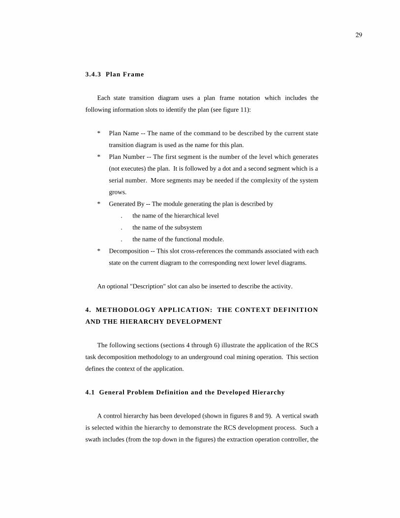
3.4.3 Plan Frame
Each state transition diagram uses a plan frame notation which includes the
following information slots to identify the plan (see figure 11):
* Plan Name -- The name of the command to be described by the current state
transition diagram is used as the name for this plan.
* Plan Number -- The first segment is the number of the level which generates
(not executes) the plan. It is followed by a dot and a second segment which is a
serial number. More segments may be needed if the complexity of the system
grows.
* Generated By -- The module generating the plan is described by
. the name of the hierarchical level
. the name of the subsystem
. the name of the functional module.
* Decomposition -- This slot cross-references the commands associated with each
state on the current diagram to the corresponding next lower level diagrams.
An optional "Description" slot can also be inserted to describe the activity.
4. METHODOLOGY APPLICATION: THE CONTEXT DEFINITION
AND THE HIERARCHY DEVELOPMENT
The following sections (sections 4 through 6) illustrate the application of the RCS
task decomposition methodology to an underground coal mining operation. This section
defines the context of the application.
4.1 General Problem Definition and the Developed Hierarchy
A control hierarchy has been developed (shown in figures 8 and 9). A vertical swath
is selected within the hierarchy to demonstrate the RCS development process. Such a
swath includes (from the top down in the figures) the extraction operation controller, the
30
section mining operations controller, the continuous mining machine controller, the
vehicle guidance controller, the tram motion controller (see appendix B), and the tram
motor controllers, with vehicle guidance being the focus.
A description of the main piece of equipment used in this process, a Joy 14CM
continuous mining machine, is given in appendix B as part of the problem definition.
4.2 The Context for the Vehicle Guidance Controller
The primary responsibility for the vehicle guidance controller is to move the
machine to desired locations. During the performance of vehicle guidance, problems
including tread slippage along the lateral or rotational directions may be encountered.
Vehicle guidance is a fundamental problem in that it interacts with other aspects of the
machine control/mining process (such as the control of the conveyor boom and the cutter
drum). Therefore, issues such as problem scope and developing a typical scenario all
have to be resolved before task analysis can be performed.
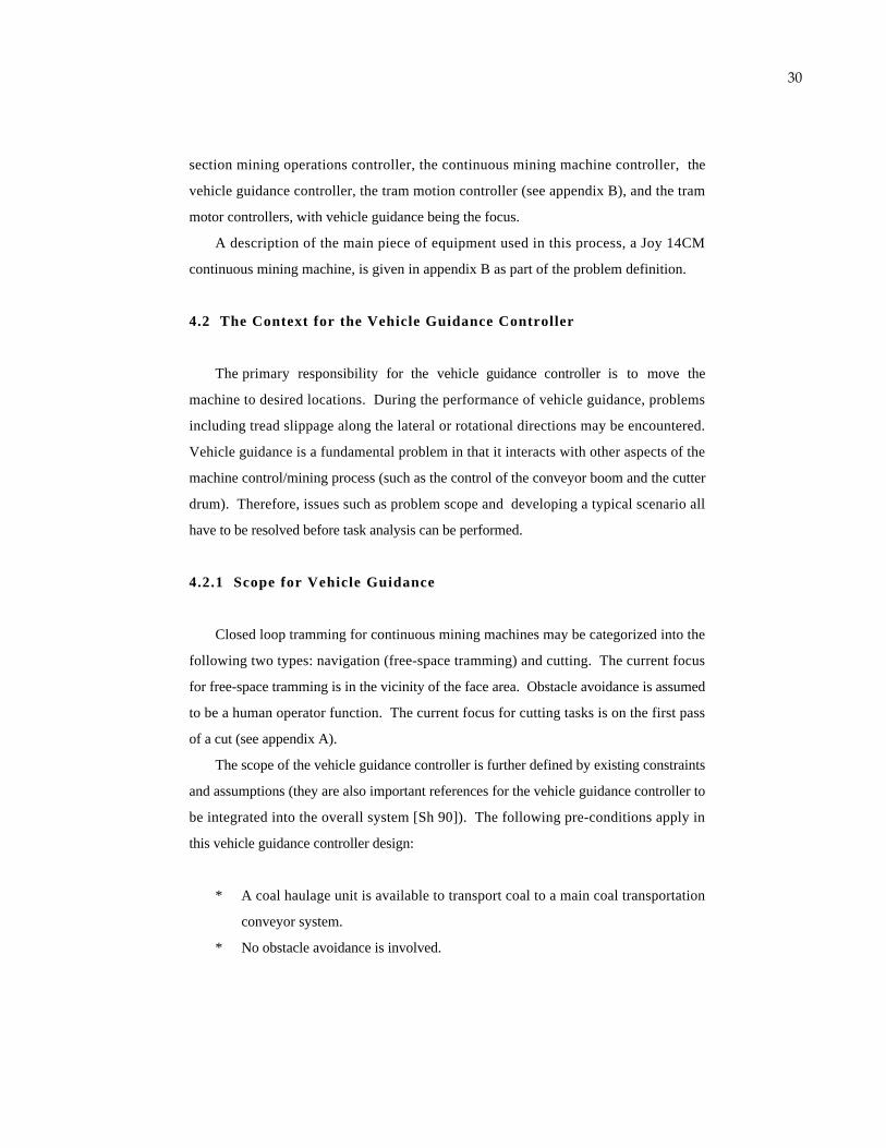
4.2.1 Scope for Vehicle Guidance
Closed loop tramming for continuous mining machines may be categorized into the
following two types: navigation (free-space tramming) and cutting. The current focus
for free-space tramming is in the vicinity of the face area. Obstacle avoidance is assumed
to be a human operator function. The current focus for cutting tasks is on the first pass
of a cut (see appendix A).
The scope of the vehicle guidance controller is further defined by existing constraints
and assumptions (they are also important references for the vehicle guidance controller to
be integrated into the overall system [Sh 90]). The following pre-conditions apply in
this vehicle guidance controller design:
* A coal haulage unit is available to transport coal to a main coal transportation
conveyor system.
* No obstacle avoidance is involved.
31
* No Coal Interface Detection (CID) system [Sc 89] is employed. The formation
of the coal seam to be cut is assumed to be regular and in extractable condition.
* The machine will pivot only to adjust its orientation (the term "yaw" is used
interchangeably with "orientation"). Assume that the pivot action does not
change the position of the machine.
* The pivot point for the machine is used as a reference for the machine position.
* The CM uses only the slow tramming speed for the purpose of simplicity.
* This vehicle guidance function must be integrated into the existing BOM
testbed, BOM/NET (appendix B). The BOM/NET system includes a set of low
level computer commands for tramming control. Therefore, the low level
constraint for vehicle guidance is that its output should be compatible with the
BOM/NET command structure and specification.
The vehicle guidance controller can assume additionally the existence of the
following conditions if it is commanded to perform a cutting task:
* The coal seam has been surveyed and the cutting location identified. A cutting
path coordinate system has been defined (see section 5).
* The machine is assumed to be located at the origin of the cut coordinates.
* Adequate machine power for the electrical, hydraulic and mechanical systems
exists.
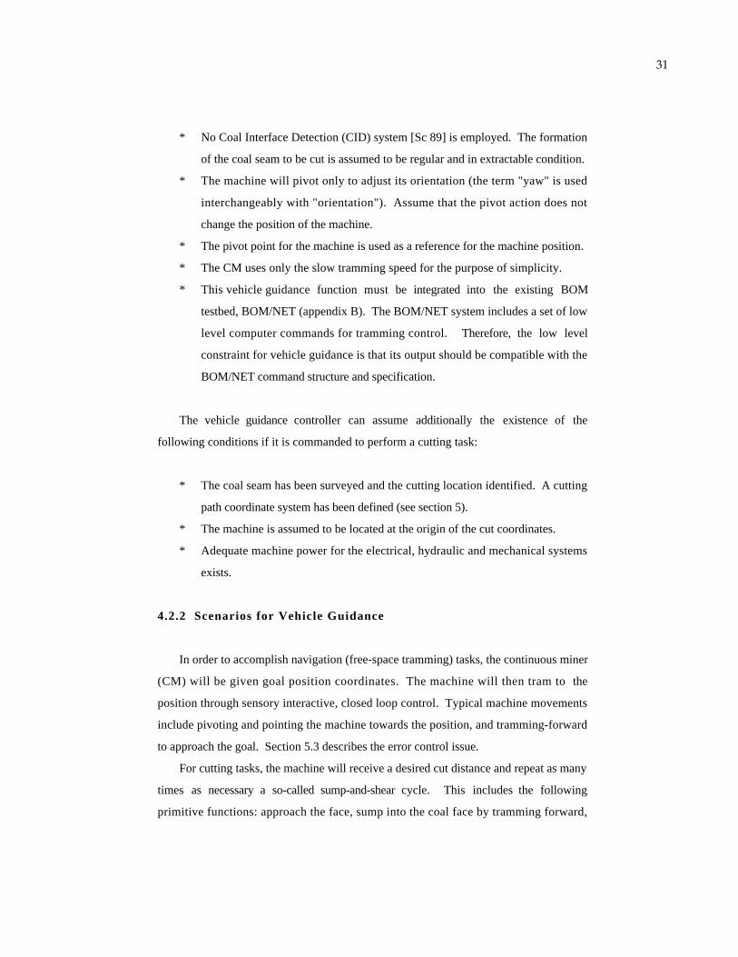
4.2.2 Scenarios for Vehicle Guidance
In order to accomplish navigation (free-space tramming) tasks, the continuous miner
(CM) will be given goal position coordinates. The machine will then tram to the
position through sensory interactive, closed loop control. Typical machine movements
include pivoting and pointing the machine towards the position, and tramming-forward
to approach the goal. Section 5.3 describes the error control issue.
For cutting tasks, the machine will receive a desired cut distance and repeat as many
times as necessary a so-called sump-and-shear cycle. This includes the following
primitive functions: approach the face, sump into the coal face by tramming forward,
32
shear coal by moving the cutting drum down to the floor, gather the cut coal and move it
to the rear of the machine, and cut the remaining coal on the floor while tramming in
reverse (see sections 5 and 6 for definitions). Similar error control (as in free-space
tramming) is used. However, more frequent correction activity is expected (due to the
cutting process).
A combined scenario may include first a navigation task to move the machine to the
coal face followed by a cutting task to extract the coal.
5. METHODOLOGY APPLICATION: TASK ANALYSIS
The discussion for a Continuous Miner (CM) and related section level and operation
level task commands is included in this section. The description includes a minimum
set of commands required for the system to perform automated operations. Therefore, the
described task commands include:
* those commands that the current equipment is not capable of performing, but
which are desirable for automation purposes; and
* those commands that are currently performed by human operators.
Some planned commands are listed without detailed description, either because the
current equipment does not have such capabilities, or because more systematic
investigation is needed before these tasks can be defined. In either case, they will be
incrementally implemented as longer term project objectives.
5.1 General Coordinate Frame Transition
As described earlier, successive transitions in coordinate frames or resolutions can be
seen among different levels in hierarchical control. Appendix A provides additional
information defining the terms used here to describe the coal mining environment. The
following is an example of such coordinate system transition:
33
* Panel/Room. At a higher level, a mine map may refer to objects such as
panels (see appendix A). Further detail within a panel is not of concern at this
level.
* Pillar ID, Entry Number. At a lower level, a map typically has a finer
resolution. Objects within a room, such as a certain pillar or a certain entry,
will be referred to.
* Representation of Pillars. At another level down, pillars may be represented in
more detail. The shape of pillars may be represented in vectors (polygons) or in
an array referring to a common coordinate system in a room.
* Path Coordinate System. A convenient way to simplify data manipulation is
using local frames originating at the starting point of a cut or a free-space
tramming task. See section 5.2 for more detail.
* Actuator Coordinate Systems. At the lowest level, actuators typically have
their own local references, such as voltages or stroke of hydraulic cylinders.
5.2 Path Coordinate Frame
Since vehicle guidance is the focus of this application, its particular coordinate
system is described in detail in this section. The vehicle guidance controller uses a local
path coordinate frame originating at the starting point of either a cutting or a free-space
tramming task to simplify computation. The vector from the starting point to the goal
is used as the forward (or Y) axis (figure 12). The starting point for a cut is set at a
point such that the cutter drum is about one meter away from the coal face. At this
point any necessary (albeit minor) adjustment of the yaw of the machine can be made to
allow the machine to line up with the direction of the cut.
5.3 Vehicle Guidance Analysis
Vehicle guidance is responsible for the motion control for the CM's. When the
control algorithm is designed, the following questions have to be answered:
* How does the machine behave given its mechanical/electrical/hydraulic design?

34
* What are the tasks that the machine must perform?
* What is a natural hierarchical organization of those tasks?
1 meter
coal face
Y
Y'
X' (machine coordinates)
X (cutting path coordinates)
Y'' '
X''' (other possible sensory coordinates)
Figure 12: Different Local Coordinate Frames
X"
Y"
(navigation path coordiantes)
In order to more fully characterize the performance of the vehicle guidance
controller, some understanding is necessary concerning the sources and kinds of errors
affecting control, the basic control strategy, and some related issues regarding the
performance of the error control of the machine motion. Huang [Hu 91] gives an in-
depth discussion of these issues, summarized in the following sections.
5.3.1 Problems Affecting Vehicle Guidance
Several environmental factors affect the performance of the vehicle guidance
controller. Irregularities in the coal seams can cause machine motion control error.
35
Irregularities of concern include oblique grade of the floor (a few degrees) and anomalies
(such as faults in the earth or rocks). A wet or muddy floor can also cause unpredictable
machine motion, such as machine slip or slide, which is nonlinear and difficult to
control.
Some physical system problems also contribute to machine motion error. In the
CM, mechanical/electrical delay exists between issuance of a motion command and the
actual motion of the tram motors [Sc 90]. Uneven speeds between two tram motors or
uneven wearing conditions between two tread sets also cause control errors.
Communication failures in the network and problems in measurement error
propagation [Ho 90-1] are additional sources of vehicle guidance errors.
Typical underground coal mining involves operating a bulky CM (see appendices A
and B) in a tight space but without proximity sensing capability on all sides of the
machine. This, combined with the above-mentioned environmental and physical system
problems, can cause the machine to bump into pillars, ventilation brattices [St 83], or
other obstacles.
5.3.2 Vehicle Guidance Error Control
Despite the fact that the problems identified in section 5.3.1 are rich enough to
warrant the consideration of applying more advanced techniques such as on-line system
identification [Bo 76, Ey 74] or adaptive control [As 84] as control solutions, for now,
however, a simpler control strategy is chosen which will merely keep a tight control on
the orientation (yaw) and the lateral deviation. In other words, the machine will be
stopped any time that the yaw or lateral error gets beyond the specified value. A new
course would be drawn from the current position to the goal and the corresponding
commands will be issued and executed. This previously incurred error will be corrected
as the machine proceeds along the new course (figure 13). Refer to [Hu 91] for more
information.
One interesting characteristic in this vehicle guidance problem is that some "non-
linear" factors may override the established control strategy in some situations. This
simple control strategy was selected in the interest of balancing the need for accurate path

36
planning against coal production efficiency (a trade-off between coal produced per hour
and cutting precision).
Goal
Figure 13: Adjustment of Path
Re-computed Path
CMX
Starting Point
OriginalPath
Y CM
Ypath
Xpath
Deviated Machine Position
Given the nature of the errors and uncertainties affecting the guidance controller and
given the simple control strategy outlined above, certain issues arise as one seeks to
minimize the adverse effect of the errors.
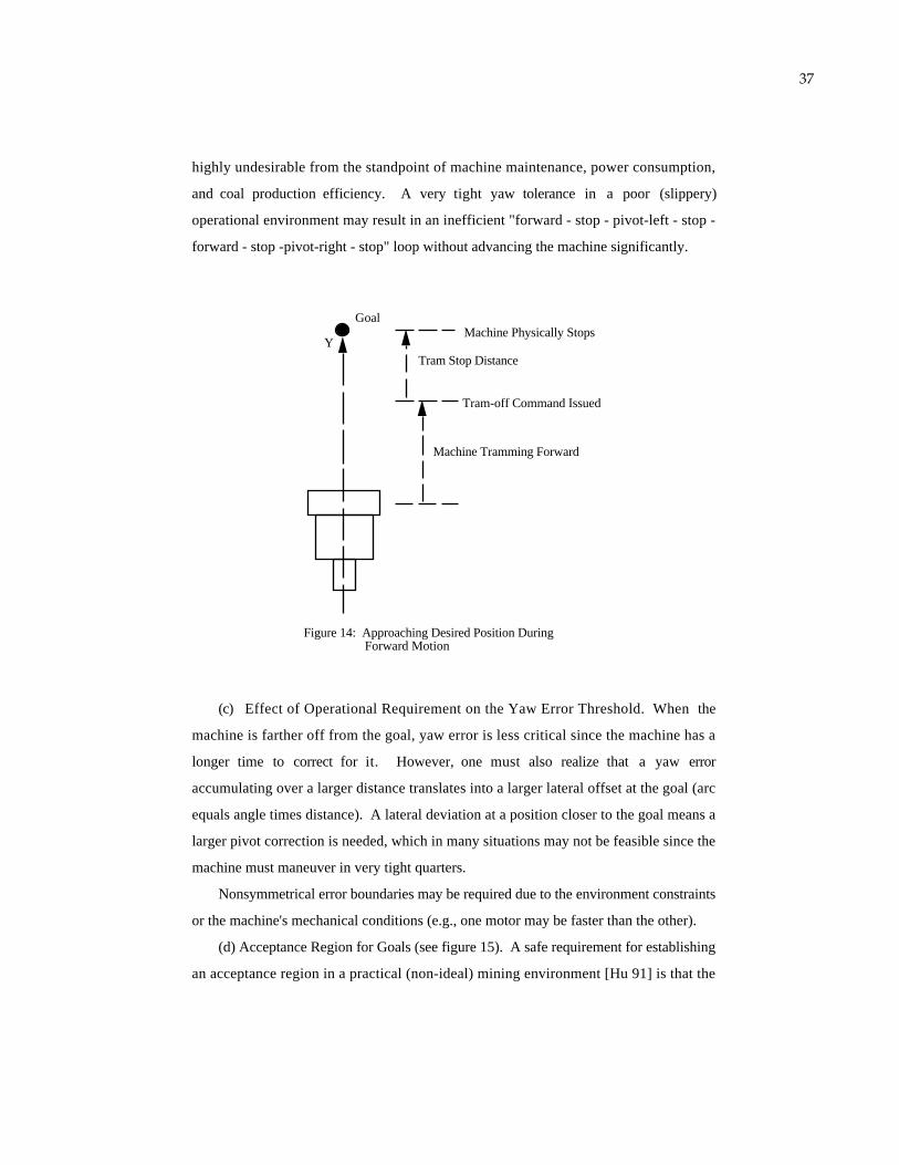
(a) Anticipative Control. As a first step approach, an anticipative type of control
will be used [An 90] as the machine approaches the goal position or orientation. The
TRAM-OFF command is sent with sufficient lead-time to allow the desired machine
stop distance to be achieved (see figure 14).
(b) Boundary for Yaw-Error Control. Forward commands will cease when the
orientation of the machine exceeds the error threshold, and the machine will pivot. There
is a trade-off between the path-following accuracy that the controller can achieve and the
frequency of tram, stop, and pivot commands required. Frequent error correction is
37
highly undesirable from the standpoint of machine maintenance, power consumption,
and coal production efficiency. A very tight yaw tolerance in a poor (slippery)
operational environment may result in an inefficient "forward - stop - pivot-left - stop -
forward - stop -pivot-right - stop" loop without advancing the machine significantly.
Y
Goal
Machine Tramming Forward
Tram-off Command Issued
Tram Stop Distance
Figure 14: Approaching Desired Position During Forward Motion
Machine Physically Stops
(c) Effect of Operational Requirement on the Yaw Error Threshold. When the
machine is farther off from the goal, yaw error is less critical since the machine has a
longer time to correct for it. However, one must also realize that a yaw error
accumulating over a larger distance translates into a larger lateral offset at the goal (arc
equals angle times distance). A lateral deviation at a position closer to the goal means a
larger pivot correction is needed, which in many situations may not be feasible since the
machine must maneuver in very tight quarters.
Nonsymmetrical error boundaries may be required due to the environment constraints
or the machine's mechanical conditions (e.g., one motor may be faster than the other).
(d) Acceptance Region for Goals (see figure 15). A safe requirement for establishing
an acceptance region in a practical (non-ideal) mining environment [Hu 91] is that the
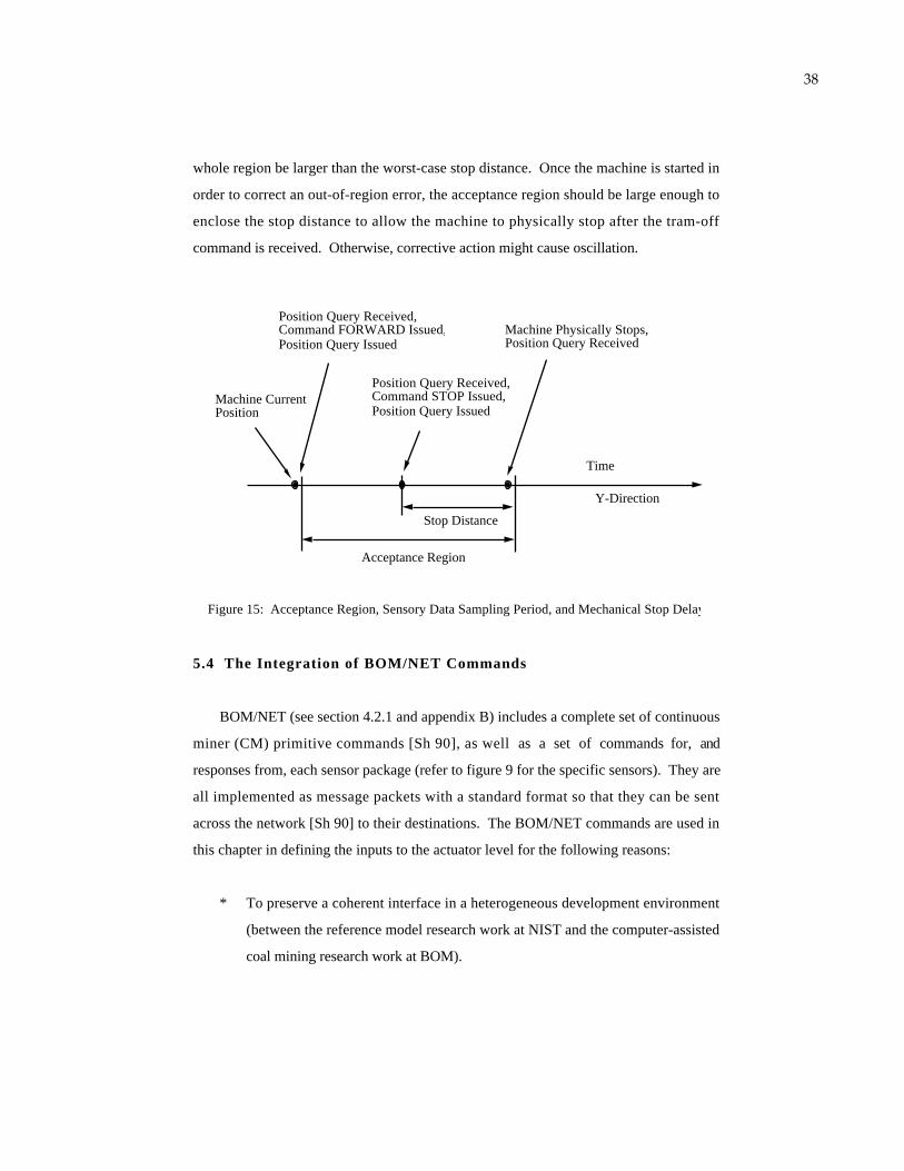
38
whole region be larger than the worst-case stop distance. Once the machine is started in
order to correct an out-of-region error, the acceptance region should be large enough to
enclose the stop distance to allow the machine to physically stop after the tram-off
command is received. Otherwise, corrective action might cause oscillation.
Position Query Received,Command FORWARD Issued,Position Query Issued
Position Query Received,Command STOP Issued,Position Query Issued
Machine Physically Stops,Position Query Received
Acceptance Region
Time
Y-Direction
Machine Current Position
Stop Distance
Figure 15: Acceptance Region, Sensory Data Sampling Period, and Mechanical Stop Delay
5.4 The Integration of BOM/NET Commands
BOM/NET (see section 4.2.1 and appendix B) includes a complete set of continuous
miner (CM) primitive commands [Sh 90], as well as a set of commands for, and
responses from, each sensor package (refer to figure 9 for the specific sensors). They are
all implemented as message packets with a standard format so that they can be sent
across the network [Sh 90] to their destinations. The BOM/NET commands are used in
this chapter in defining the inputs to the actuator level for the following reasons:
* To preserve a coherent interface in a heterogeneous development environment
(between the reference model research work at NIST and the computer-assisted
coal mining research work at BOM).
39
* In the RCS, the primitive level deals with system dynamics. In the BOM/NET
protocol, commands specify dynamic characteristics for each actuator, such as
velocity and maximum time limits. Therefore, a correspondence can be found
between these two systems.
For these reasons, the BOM/NET CM commands are used as the prim level outputs
from the RCS hierarchy. The BOM/NET commands are generally specified for each
individual actuator, except for the tramming commands, where one command involves
both tram motors (since this is how CM control switches are wired).
5.5 Level 1 -- Actuator Level
The output of the actuator level TD module contains electrical/hydraulic command
signals to each actuator [Jo 82]. The input to this level is the primitive level output
defined for each subsystem as described in the above section.
The following Joy CM actuator functions and function categories were derived from
the Joy CM service manual [Jo 82] and BOM/NET Specification [Sh 90], where
complete command names and formats are listed:
* Tramming
. forward slow / fast
. reverse slow / fast
. left turn forward / reverse
. right turn forward / reverse
. pivot left / right
* Appendage Hydraulic Motions
. conveyor tail up /down, left / right
. shear up / down
. stabilization jack up / down
. gathering head up /down,
40
* Latching On/Off
. pump motors
. cutter head motor
. conveyor
. main control switch (safety relay)
5.6 Level 2 -- Primitive Level
As mentioned, the primitive level is also referred to as the dynamic control level.
However, in the case of mining equipment, most controls are of the step function type
(on/off or fast/slow). Therefore, the primitive level computations are much simplified
[Hu 90-3]. Section 5.5 specified three categories of commands. For the tramming and
the appendage commands, the prim level controller determines their range, rate, and
maximum safety time, whereas for the latching commands, only the actions of 'on' or
'off' are needed.
The following sections (5.6.1 through 5.6.5) are organized according to the
architecture as shown in figure 9.
5.6.1 Tram Motion Control Module
The main objective for the tram motion control is the performance of the closed
loop control on the goal positions or orientations given by the vehicle guidance
controller.
Path coordinate frames can be used for the continuous miner (CM) to perform tram
motion control. However, a center-following approach may also be used in free-space
tramming tasks. In such an approach, the desired wall clearance (proximity) is a
predefined quantity. Since the wall surface is generally rough, range information must
be defined statistically. Multiple readings in the vicinity are taken and a filtering process
is used to compute the ranges. In some cases when the equipment needs a linear
prediction over distances, such as for the trend of wall clearance, for the path of an
object, or for the next key pose, a second stage filtering process (a time series type of

41
analysis is a good candidate for this purpose) may be required. Filtered statistical range
data will be used, and a cascaded filtering process is seen [Hu 82].
The tram motion controller can have additional responsibilities including the
determination of the turning method (pivot or one tram halted) and the determination of
the tramming speed (slow or fast), but they are beyond the scope of this chapter (see
section 4.2.1).
The following are the tram motion control input commands for the CM at the
primitive level; they also correspond to the names of planes which carry out the
commands at the primitive level:
CM-STRAIGHT
This command is used primarily in navigation (free-space tramming) to move the
machine to a specified location. This command will refer to a path coordinate system
computed in the e-move NAVIGATE-TO-Zi command. Future enhancements to this
program include a decision making process, either through human interaction or rule-
based inference, to determine whether to use the forward or the reverse mode of operation
to approach the goal.
CM-PIVOT
This command is used when pivot is needed (primarily during navigation tasks) to
point the machine towards the goal. Future enhancements to this plan can include a
post-pivot position verification and correction.
APPROACH-FACE
This command generally means to move the machine forward to have the cutter
drum in contact with the coal face. There are two situations where this plan is used:
* at the beginning of a cutting task,
* after the CUSP-REMOVAL task during a cut (see later in this section for
definition).
42
The first step the machine performs during a cut is to approach the coal face
coincident to the direction of the cut (see section 5.2 for the reference coordinate frame).
The precision of the direction is important to the straightness of the whole cut. The
stabilization jack is lowered (before the machine trams forward) to provide a more stable
platform during cutting operations. Because of precision requirements, the yaw error and
the lateral deviation of the machine are tightly monitored and controlled. The operator
enters an error specification according to factors such as floor condition, since, on a
slippery floor, it may not be possible for the controller to achieve path accuracies that
are possible under drier conditions. The completion of this task is defined as when the
cutter motor current exceeds a pre-defined threshold. This occurs, under normal
conditions, soon after the cutter drum makes contact with the coal seam.
The CM is required to re-approach the coal face after each CUSP-REMOVAL task.
In this situation, the precision of the direction is not as critical, which means the
maximum allowed error may be larger. A specification for the desired distance may be
used (instead of the cutter current threshold) as the task completion criteria.
SUMP
Sump means pushing the turning cutter drum into the coal face by the force of
forward tramming while maintaining the height of the drum. The first increment of the
sump distance (approximately 15 centimeters, per discussion with the BOM researchers
[Ho 90-2]) is critical to the straightness of the whole sump and is the only time during
the execution of a SUMP command that the yaw of the machine is controllable.
Afterwards the machine is allowed to sump in, without control of yaw, for its entire
desired distance.
The cutting height measured from the floor must be given. The height will be
converted to a drum angle in this level. Note that usually an initial-approach-to-the-face
command precedes the sump command, hence this parameter may serve only for
checking purposes.
SHEAR
This command requires close coordination with the boom control module (discussed
in section 5.6.2). After the cutter drum is sumped into the coal, the coal can be
43
excavated by shearing down the rotating drum (see the DRUM-TO-ANGLE command in
the following section). Lateral or yaw deviation may be severe due to the large cutting
force involved, yet no attempt will be made to correct the error so that static friction
force may be maintained on the treads. An exception exists when the cutting reaction
force is large enough to push the machine away from the face. During such
circumstances, forward motion may be applied to re-engage the machine in the coal so
that shearing can resume.
CUSP-REMOVAL
A cusp (a ridge of coal) can be left on the floor due to the geometry and the
shearing-down motion of the cutter drum. The cusp must be removed. The machine
performs a reverse motion while the cutter is turning at roughly the floor height (see the
command above). The goal point for this command is the location where the last sump
started. The yaw error is not monitored since, from a production efficiency standpoint,
there is no point applying a lot of corrective action for relatively small amounts of coal.
In other words, the machine trams reverse with an expectation that the goal point can be
reached without yaw control. This is due to the fact that there is much less coal to cut,
the reacting force is in turn much smaller, and, as a result, the machine is less likely to
slip.
If the machine can not proceed because of an obstacle (see section 5.3.1), the
guidance controller will not attempt to remove any remaining coal. Whether or not the
cusp removal is completed, the controller will perform a pivot motion in an attempt to
re-orient the machine to prepare for the next sump-and-shear cycle.
5.6.2 Boom Control Module
DRUM-TO-ANGLE
This command is used in coordination with the SHEAR command discussed in the
above section. This command moves the rotating drum to a desired shearing angle to
excavate the coal. A cusp may be left on the floor due to the shape and the angular
motion of the drum.
44
Normally the cutter shears down to the floor. In this case, the shearing height
(angle) is the same as the sump height (angle). However, under certain conditions the
cutter may shear down lower or higher in order to follow the coal seam, to make more
room for machine maneuvers, or because rock may exist at the floor.
5.6.3 Stabilizer Control Module
JACK
This command moves the stabilization jack to a desired angle. However, other
sensory feedback methods can be suggested due to the fact that it appears difficult for the
upper-level planner to compute, in advance, a precise jack target angle. Servo loops
such as sensing the CM inclination or sensing the jack hydraulic pressure may be
considered. Several factors, stated below, have to be taken into account in performing
such servo function:
(a) In the current CM hydraulic circuit, a relief valve [Jo 82] with a manufacturer's
preset relief pressure is installed to protect the maximum line pressure in the circuit. It
is still a good safety measure to monitor the stabilizer hydraulic pressure during the
jacking operation and/or to use it as an auxiliary control variable in the servo loop.
(b) When shearing starts and the cutting force is applied, not only does the jack
hydraulic line pressure increase, but the inclination of the continuous miner (CM) also
may change. These both have to be taken into account when the upper level (e-move)
stabilization planner computes and sends down the inclination setting criteria. A
continued monitoring of these two parameters during the whole sump-and-shear cycle
may be necessary.
(c) The target inclination angle may not always be set at zero degrees. It must be
determined by the coal seam variation and by anomalies on the floor (rocks, for
example).
The requirements for the inclination information are also discussed in the e-move
level STABILIZE command.
5.6.4 Gathering Head Control Module
45
GATHERING-PAN-SETTING
The desired gathering pan elevation must be set before the CM can gather the cut
coal or perform free-space tramming.
Note that the switch function for the gathering head is controlled by the conveyor
switch (refer to the e-move level corresponding reset command for more detail).
5.6.5 Conveyor Control Module
CONVEYOR-SETTING
This command can be used either to reset the coal removal subsystem for various
tasks or to align the conveyor boom to the haulage unit after the haulage unit reaches the
CM. The following parameters are involved:
* latching: on/off of the conveyor motion;
* swing_angle: the relative angle from the previous position. Set the boom to
the CM center line when performing a navigation task, or set it to the middle of
the swing angle when performing an alignment for loading.
* elevation_angle: the target elevation angle, with the reference being at the
lowest conveyor position, corresponding to the desired conveyor tail height.
This angle would be zero degrees for a navigation reset. For aligning the tail to
the haulage unit, the target elevation angle would be a fine tuning value relative
to the highest position (refer to the e-move level discussion). At the higher
levels, absolute coordinates would be used to specify the interface requirement
(the height of the conveyor boom) so as to properly transport the coal from the
CM to the haulage unit. However, in lower level maneuvering, the locally
centered elevation angle information is used.
CONVEYOR-TAIL-LOAD
This command is used to move the tail to load the coal on the haulage unit. The
following parameters are involved:
46
* elevation: the necessary relative elevation angle if coal builds up on the
haulage unit.
* range: the relative boom swing range (horizontally) to load the coal efficiently.
5.7 Level 3 -- E-Move Level
The elementary movements (e-moves) that the CM is capable of performing (i.e.,
the inputs to the e-move level) are discussed in this section. E-moves are coordinated
subsystem motions designed to achieve some key positions, and/or orientations (a
typical key position is a corner where the CM is to make a turn) [Al 88]. The length of
the path for an e-move is typically the distance that can be directly observed by the on-
board sensors.
Outputs from the e-move level such as motion paths generated for all appendages
have been checked to be free of collisions and singularities. Navigation paths, expressed
in terms of intermediate goal points, are obstacle free and optimized (shorter distance,
less traffic, better floor condition, etc.).
Since the main power control subsystem and the support subsystem (figure 9)
involve only the actions of switching on and off, it may be assumed that there is no need
for a prim level and therefore the e-move level directs its outputs to the actuator level.
5.7.1 Initialization
POWER-UP
Turn on the pump motor. By doing so both the hydraulic circuits and the electrical
circuits are charged up, so that both systems become controllable. The charging status
of these circuits should be monitored and the existence of non-recoverable error signals
would result in a shut down of the machine.
The following five commands are executed to perform all necessary
initialization/test procedures for all the CM subsystems when the machine is started.
COAL-CUTTING-SUBSYSTEM-INITIALIZATION
47
COAL-REMOVAL-SUBSYSTEM-INITIALIZATION
GUIDANCE-SUBSYSTEM-INITIALIZATION
MAIN-POWER-SUBSYSTEM-INITIALIZATION
SUPPORT-SUBSYSTEM-INITIALIZATION
The initialization work includes component availability verification, component
calibration, information base initialization, etc. The initialization must be completed
without error before an extraction or a navigation operation can begin.
5.7.2 Guidance Control Module
GUIDANCE-SUBSYSTEM-RESET
This command is executed so that the subsystem becomes ready to perform any
tramming related tasks. Depending on the task types, the affected sub-components vary.
For example, to perform global navigation, the mechanical guidance subsystem (figure
9) may need to be retracted.
NAVIGATE-TO-Zi
This is a plan allowing for the movement of a CM in non-cutting situations. The
goal points for this command are a series of key points (Zi) which route the CM to its
destination. These points define a piecewise linear approximation of the trajectory. The
distance between two consecutive points is typically limited to correspond to on-board
sensor ranges.
Two of the major planning functions normally performed at the e-move level,
namely kinematics computation and obstacle avoidance, are performed by human
operators at this stage. In other words, when an operator sends a goal position to the
vehicle guidance controller, he or she must make sure that this position can be reached
by the mining machine and that intermediate planning is neither needed nor intended.
At the beginning of this task, the GUIDANCE-SUBSYSTEM-INITIALIZATION
command will verify the current position information stored in the computer. The goal
position will also be entered (possibly from an operator input channel). The controller
then computes a vector from the machine's current position to the goal, assuming there

48
is no obstacle in between. The angle between the current machine yaw and the goal
vector will be computed and used as a transformation angle. The reference for the
machine will be transformed to a new coordinate system that uses the goal vector as the
Y-axis. Such planning activity normally results in a plan consisting of a pivot action to
point the machine to the goal position and a forward motion to move the machine to the
goal.
A future enhancement to this plan is the ability to determine whether to use the
forward or the reverse mode in approaching each goal position. Criteria for making such
a decision may include power/time efficiency, physical constraints along the path, and
the need to set up a convenient orientation for the next following task.
BOX-CUT
A cut typically requires the machine to cut in two passes [Appendix A]. A box cut
refers to the first pass. A box-cut plan receives a goal (5 meters, for example). This
goal is translated to the goal coordinates, (0, 6, 0), in the path coordinate system. The
machine then cyclically performs a series of primitive commands (defined in the previous
section) in order to do the work of cutting coal. A clean-up task to clean up loose coal
on the floor may be required but is currently not included in the plan. This series of
operations executes in cycles until the 5-meter cut distance has been reached. The
operator needs to be able to suspend this plan at any stage, record the status, and resume
the operation as desired. One occasion to suspend the operation occurs when the haulage
unit is full.
BACKOUT
This command is used primarily when the machine has finished its five meter cut
and needs to get back to the origin of the path coordinate frame. This command is
designed to be highly user-interactive at this stage, expecting that problems may arise
during the course of long-distance reverse tramming. It is desirable that such user
interactions become part of the machine's planning capability in the future. The cutter
drum will be raised before the machine trams in reverse.
5.7.3 Coal Cutting Control Module
49
COAL-CUTTING-SUBSYSTEM-RESET
The cutter motor should be commanded 'off' for the navigation tasks and 'on' for the
extraction tasks. The drum is reset to its middle height in a navigation task and is
usually reset at the cutting height5 for a sump-and-shear operation. Typically the cutting
height is the coal seam thickness, unless more machine clearance is needed or a loose
roof needs to be removed [Be 87]. The jack is set to high during navigation, and can be
set to low for cutting tasks.
STABILIZE
This command lowers the hydraulic stabilization jack to provide a counteracting
force during a shearing cycle. The planner at this level has to compute the stabilization
requirements for the primitive level JACK command based on the following
information: coal seam variation, floor formation and grading, counteracting force
requirement during the shearing cycle, and the maximum hydraulic line pressure (see the
discussion in section 5.6.3). The primitive level controller will then servo according to
this derived criterion (represented either as a CM inclination or others) to stabilize the
machine. This level would only consider 'whether the CM is stabilized.'
5.7.4 Coal Removal Control Module
COAL-REMOVAL-SUBSYSTEM-RESET
The conveyor motor switch position needs to be properly selected. When this
command is used to reset the subsystem for navigation tasks, the conveyor is set to 'off';
for the extraction operations, the conveyor is turned on.
The conveyor boom would be set to the lowest position for a navigation task and
the highest for a cutting task. Another alignment command will be discussed later to
make necessary adjustments to the height. The CM's are designed so that the conveyor
boom normally can not go below the height of normal haulage units (see COAL-LOAD
5In some mining practice, a sump from the bottom may alternatively be used for moreefficient production.

50
e-move for exceptions). At this level, the unit of 'meter' is used. It will be converted
into an actuator angle as an input to the primitive level.
The horizontal angle of the conveyor boom also needs to be set. A typical position
would be at the CM centerline. As above, the later alignment command may make more
adjustments to the boom angle. This angle will be converted to a relative amount of
swing for the conveyor boom as an input to the primitive level.
The gathering pan height needs to be set. For navigation, the gathering pan will
have to be in its raised position. For cleaning up coal, it will be kept at a floating (on
the floor) position [Be 87].
COAL-REMOVAL-SUBSYSTEM-ALIGN
This command is used prior to the cutting operation. Typically the haulage system
would approach the CM and the two machines perform an alignment operation (refer to
the corresponding command in the equipment level for more detail). The definition of
the alignment pattern determines the conveyor boom swing angle during the coal loading
operation. This will be explained in the next COAL-LOAD command.
The height of the CM conveyor boom for a proper alignment defined in the global
frame needs to be specified. Although the equipment level planner computes a nominal
target value for the height, the local ground situation can affect the relative heights
between two machines and therefore the target value will be computed on-line. The
conveyor boom would be placed at the middle of the swing range for a proper alignment.
COAL-LOAD
This command directs the conveyor boom to load the coal during the extraction
operation. The first step is to check the coal removal subsystem reset and the alignment
requirements as discussed before. A replan to re-invoke those commands may be
necessary if the requirements are not met. The next step is to compute a conveyor boom
swing pattern according to the actual haulage system alignment. A boom elevation
pattern according to the haulage capacity, in order to load the cut coal efficiently, should
also be computed. The better the alignment is defined and accomplished, the easier
swing angles can be derived. However, this may mean a very difficult machine
maneuver (to achieve such precise alignment). Another approach is to compute the
51
swing and the elevation angles in real-time (sensory interactive) by measuring the
constantly changing alignment angles as the machines move. Such computation models
would be installed in the world model.
Note that due to local ground situations, it is not always possible to elevate the
conveyor boom high enough and jamming the boom is fairly common [Be 87].
As required, the world model may include a mathematical model to compute the
conveyor swing patterns for the system to achieve the fastest and most evenly distributed
haulage loading.
5.7.5 Support Control Module
CABLE-TENDING
This may be a required task for a fully automated machine, but for the present the
required actions are taken by human operators.
5.8 Level 4 -- Equipment Level
This section discusses the input commands for the continuous mining machine
controller residing at the equipment control level.
START-UP-CM
Electrically and hydraulically power the CM so that it becomes controllable.
MACHINE-TEST
This command is used in the initialization period to verify machine health. The
actions include a static shift-start check as suggested in the CM service manual [Jo 82]
(for part wear assessment), and the checks as discussed in the next section (the section
level). Machine calibration and data base initialization will also be performed.
CM-RESET
Depending on which plan is to be executed, the CM has to be reset accordingly.

52
ALIGN-TO-THE-HAULAGE-SYSTEM
The criteria for the alignment may include the machines center line relative bearing,
the clearance at the facing ends, and the CM conveyor boom positions. The alignment
criteria are affected by the types of on-board sensors as well as the type of haulage
systems used. If a continuous haulage unit is used, the coordination strategy may be
defined as:
(a) Prior to cut: The continuous haulage unit would physically engage with the
CM. The CM will then position the boom to complete its ALIGN-TO-THE-
HAULAGE-SYSTEM task.
(b) During the cut: The CM COAL-LOAD e-move command will swing the boom
and load the coal. Fault conditions may occur in the continuous haulage unit: the
system may become jammed, it may be stretched to its limit, it may come in contact
with corners as it turns, etc. In these situations, the required action for the continuous
haulage unit is to stop and send a pause signal to the CM.
See section 3.3.1 for the other situation (when shuttle cars are used).
CUT-LOAD-PAUSE
This task essentially sends commands to all its subsystems (figure 9) to perform a
cut (see the corresponding plan in section 6 for the specific command sequence). It also
coordinates with the haulage unit for removing the coal from the face area.
If shuttle cars are used to transport the coal, generally several car loads are needed for
a cut. A 'pause' parameter can be used. When the 'pause' has a value of '1,' the haulage
unit is not available. The CM has two options under this situation: wait and do
nothing, or cut without loading to a maximum allowed amount and load the coal when
the haulage unit becomes available again. These options are defined as different
commands which can be seen below. It is assumed that during the waiting period the
CM is not required to stop the cutting drum, the gathering head, and the conveyor. The
value of 'pause' can be supplied by the haulage unit through the world model control
hierarchy.
The cutting approach angle relative to the coal face must be given. For a straight
cut the cutting angle is 90 degrees relative to the face, whereas for a cross cut the cutting
angles will be a series of incrementing angles (a cross cut pattern can be found in the

53
reference [An 89]). Note that research [Li] has shown that, in order to make a more
efficient cross cut, the CM should make a straight cut beyond the intended intersection
then back up to make the cross cut.
CUT-NO-LOAD-PAUSE
This command directs the CM to continue cutting during a wait for the haulage
unit. There is a maximum amount of coal it is able to cut before the loose coal
prohibits the CM from advancing. The receipt of a 'pause' signal means that the haulage
system has become available again. The cutting process would be stopped to allow the
CM and the haulage system to realign.
CLEAN-UP-PAUSE
This command can be executed after the above command when there is loose coal on
the floor that may require the CM to turn to different angles in order to clean up all the
loose coal. If problems occur (e.g., the shuttle car is full) before the floor is clean, a
'pause' signal will be received and the CM will pause and wait. Note that totally
asynchronous cutting and loading actions may form and they need to be avoided.
NAVIGATE
A destination (a global position in the mine) where the next operation will take
place must be given.
CM-SHUT-DOWN
There are different shut down devices installed on the Joy 14CM mining machine
such as circuit breakers, main switch, emergency switch, and panic bar. Any of these
can be switched to activate a shut down.
CUTTING-BIT-MAINTENANCE
A currently non-existent capability, required actions are assumed to be taken by
human operators.
5.9 Level 5 -- Section Control Level
54
The section control level handles face area production and related functions,
including coordinating each individual machine's activities and summarizing the
production status. Although the section level controller is not intended to be a
replication of a conventional 'section foreman' [Bu 68], similarities can be seen.
The following commands are the inputs to the section mining operations controller
residing at the section control level:
SECTION-INITIALIZATION
This task is applicable only when a new section or a new mining plan is started;
afterwards, a SHIFT-START-INITIALIZATION task can be used.
The work in this task includes:
* Count the required resources designated by the upper levels.
* Derive the starting locations for the machines. For example, in a five-entry
development, send the entry #3 coordinates to the machines.
* Route shuttle cars according to 'right' and 'left' designations when applicable [St
83].
A satisfactory summary report from the above procedures, plus other requirements
such as resource availability and production goal achievability at the end of the
initialization period, should set the system to the ready state.
SHIFT-START-INITIALIZATION
The idea of a 'shift' serves as a natural intermission point for work such as
preventive maintenance, equipment exchange, or production analysis to be performed.
Subsequent adjustments may be needed (these cause changes in the state variable
values). Consequently, the changed state variable values have to return the 'ready'
condition before the next shift starts.
The following are some possible procedures that either exist or can be designed for
evaluating the readiness of the shift:
55
* A calibration procedure that compares the test commands and the sensory
feedback to evaluate the readiness of each piece of equipment. Some of the I/O
channels on the CM controller are used to provide diagnostic information, such
as the main pump pressure information. The CM will not become controllable
unless the main hydraulic pressure is up.
* A background statistical analysis algorithm using the on-line machine operation
data to provide long-term machine health trend prediction.
* An expert system [Mi 89] for diagnosing the CM's electrical system,
mechanical system, or hydraulic system problems.
* A machine start up sequence.
More comprehensive initialization procedures can be designed. However, since not
all the required information is available, enhancement of this initialization task is left as
future implementation work.
SHIFT-END-WRAP-UP
Equipment may be commanded to backout after completing the last task in a shift
for a routine check. Some equipment may be scheduled to retreat for a major overhaul.
Summary reports are generated.
ROOM-AND-PILLAR-ADVANCE-IN-AREA-#R
The section planner at this level will derive a mining plan and send down a
decomposed cutting sequence to all involved equipment.
The '#R' referred to here is only a general representation for any planned mining
area. The formal data structure and data description for the mining area need to be
designed as part of the world model. In such a design, both the computation efficiency
and current convention (the way mine operators and engineers describe their mining
plans) will be taken into account.
EMERGENCY-SHUT-DOWN [Jo 82];
This command is activated in response to equipment health, human safety, or
environmental condition warning generated by the monitoring system. Action is taken
56
to stop production in time to avoid a hazard and to send the machines into a safe idle or
shut down state.
EQUIPMENT-RELOCATION
Equipment can be relocated for purposes such as maintenance, replacement, or safety
backout.
The world model support for this section mining operations controller would include
a timing analysis model for machine coordination, such as shuttle car (if they are used)
changeout timing [St 83]. The world model support would also include Federal and state
regulations as well as a map of the mine section(s) with a proper resolution.
5.10 Level 6 -- Production Control Level
The following commands are the inputs to the extraction operation #i controller
residing at the production control level. Only those commands that are related to the
previously discussed lower level commands are included:
VIRTUAL-CELL-FORMATION
One responsibility for the production control level is to allocate required resources
so that the production goals can be achieved. A 'virtual cell' [Mc 82] is formed as a
work unit and will be managed by the section control level controller.
PRODUCTION-OPERATION
The production goal for the i'th extraction operation subsystem, in terms of
tonnage, and the extraction method (such as room-and-pillar or long-wall) must be
included.
5.11 The Resulting Task Tree
A task tree, shown in figure 16, describes the decomposition of the higher level
tasks to the lower level tasks. The primitive level output commands are decomposed as
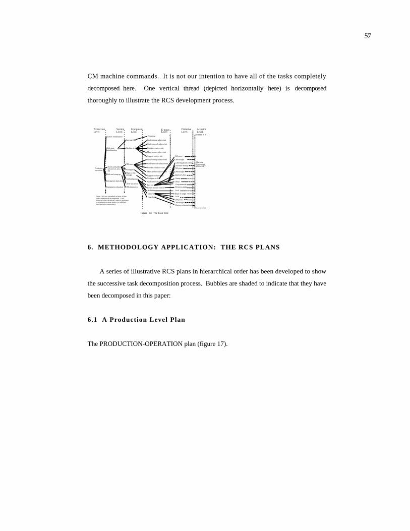
57
CM machine commands. It is not our intention to have all of the tasks completely
decomposed here. One vertical thread (depicted horizontally here) is decomposed
thoroughly to illustrate the RCS development process.
Section Level
ProductionLevel
EquipmentLevel
E-moveLevel
Productio-operation
Section-initialization
Shift-start-initialiazation
Equipment-reloaction
Emergency-shut-down
Shift-end-wrap-up
Room-and-pillar-advance-in-area-#R
Start-up-CM
Machine-test
CM-reset
Naviagate
Align-to-the-haulage
Cut-load-pause
Clean-up-pause
CM-shut-down
Power-up
Coal-cutting-subsys-init
Coal-removal-subsys-init
Guidance-subsys-init
Main-power-subsys-init
Support-subsys-init
Coal-cutting-subsys-reset
Coal-removal-subsys-reset
Guidance-subsys-reset
Main-power-subsys-reset
Support-subsys-reset
Navigate-to-Zi
Coal-removal-subsys-align
Stabilize
Coal-load
CM-pivot
CM-straight
Gathering-head-settingConveyor-setting
Approach-face
Sump
ShearCusp-removal
Backout
Jack
Conveyor-boom-load
PrimitiveLevel
ActuatorLevel
Box-cut
MachineCommands(BOM/NET)
Boom-motion-control Drum-to-angle
CM-pivot
CM-straight
Drum-to-angleJack
Figure 16: The Task Tree
Note: It is not intended to have all the tasks completed decomposed. One selected vertical thread, vehicle guidance, is explored in more detail (to interface the machine commands).
CM-pivotCM-straight
6. METHODOLOGY APPLICATION: THE RCS PLANS
A series of illustrative RCS plans in hierarchical order has been developed to show
the successive task decomposition process. Bubbles are shaded to indicate that they have
been decomposed in this paper:
6.1 A Production Level Plan
The PRODUCTION-OPERATION plan (figure 17).
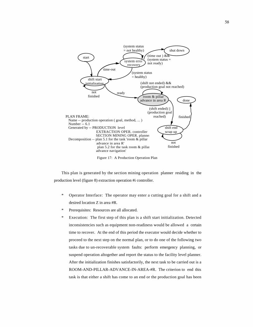
58
not finished
PLAN FRAME: Name -- production operation ( goal, method, ... ) Number -- 6.1 Generated by -- PRODUCTION level EXTRACTION OPER. controller SECTION MINING OPER. planner Decomposition -- plan 5.1 for the task 'room & pillar advance in area R' plan 5.2 for the task room & pillar advance navigation'
shift startinitialization
time-out
system errorrecovery
(system status= healthy)
not finished
room & pillaradvance in area R
shut down
(shift ended) || (production goal
reached)
done
shift endwrap up
(time out ) &&(system status =not ready)
(system status= not healthy)
ready
finished
(shift not ended) &&(production goal not reached)
start
Figure 17: A Production Operation Plan
This plan is generated by the section mining operation planner residing in the
production level (figure 8) extraction operation #i controller.
* Operator Interface: The operator may enter a cutting goal for a shift and a
desired location Z in area #R.
* Prerequisites: Resources are all allocated.
* Execution: The first step of this plan is a shift start initialization. Detected
inconsistencies such as equipment non-readiness would be allowed a certain
time to recover. At the end of this period the executor would decide whether to
proceed to the next step on the normal plan, or to do one of the following two
tasks due to un-recoverable system faults: perform emergency planning, or
suspend operation altogether and report the status to the facility level planner.
After the initialization finishes satisfactorily, the next task to be carried out is a
ROOM-AND-PILLAR-ADVANCE-IN-AREA-#R. The criterion to end this
task is that either a shift has come to an end or the production goal has been
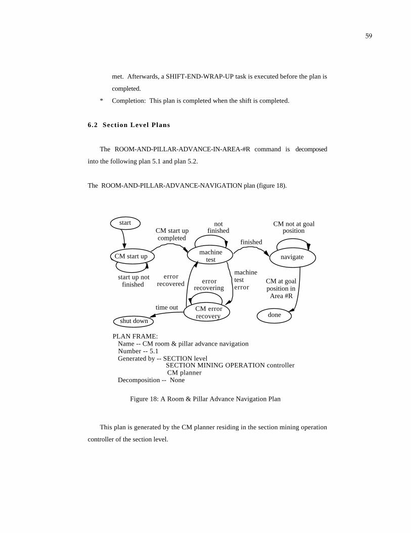
59
met. Afterwards, a SHIFT-END-WRAP-UP task is executed before the plan is
completed.
* Completion: This plan is completed when the shift is completed.
6.2 Section Level Plans
The ROOM-AND-PILLAR-ADVANCE-IN-AREA-#R command is decomposed
into the following plan 5.1 and plan 5.2.
The ROOM-AND-PILLAR-ADVANCE-NAVIGATION plan (figure 18).
PLAN FRAME: Name -- CM room & pillar advance navigation Number -- 5.1 Generated by -- SECTION level SECTION MINING OPERATION controller CM planner Decomposition -- None
CM start up
start up not finished
CM start up
CM start up completed
machine test
not finished
finished
error recovered error
recovering
CM error recovery
shut down
navigate
done
CM at goal position in Area #R
CM not at goal position
time out
machinetesterror
start
Figure 18: A Room & Pillar Advance Navigation Plan
This plan is generated by the CM planner residing in the section mining operation
controller of the section level.

60
* Operator Interface: The operator may need to be able to set the intermediate
goals for a given destination. He may also need to be able to modify the points
during the navigation.
* Prerequisites: The CM is assigned to a particular section mining operation.
* Execution: This plan starts with a machine test and a start-up procedure
followed by a navigation task to reach a more specific location in that area.
The "specific location" has a resolution that is of about one order of magnitude
finer than that of "area #R," as a result of the hierarchical decomposition.
* Completion: This plan is completed when the CM reaches position Z in area
#R.
The ROOM-AND-PILLAR-ADVANCE plan (figure 19)
This plan is generated by the CM planner residing in the section mining operation
controller of the section level.
* Operator Interface: The operator may need to be able to observe the alignment
operation and determine this operation's completion status for the involved
equipment.
* Prerequisites: The CM is at the desired location in area #R, otherwise the
above navigation plan may be activated first.
* Execution: The conveyor boom at the rear of the CM is to be aligned with the
haulage unit first (this means the haulage system has to be in place already),
then the CUT-LOAD-PAUSE activity can begin. Pause signals can be
generated and can happen in various situations. For example, if the haulage
unit is away, full, jammed, or has other problems. The conditions for the CM
to exit the cut state are that either the cutting distance is reached or an external
pause signal is received. In the former case the system goes into a 'wait' state,
and in the latter case the plan is completed.
* Completion: This plan is completed when the cutting goal for a shift is
achieved.

61
PLAN FRAME: Name -- 'CM room & pillar advance in area #R' Number -- 5.2 Generated by -- SECTION level SECTION MINING OPER. controller CM planner Decomposition -- Plan 4.1 for the task 'cut-load-pause'
done
align tothe haulage system
wait forhaulage
cut-load-pause
(haulage not aligned) or (haulage pause = T)
(haulage aligned) &&
(boom not aligned)
haulagenot
alignedhaulagealigned & (haulage pause = false)
CM & haulage aligned
(cutting distancenot reached) &
(haulage pause = T)
(haulage pause = false) &
(cutting goal not achieved)start
CM position = desired
Figure 19: A Room & Pillar Advance Plan
shift cutting goal achieved
6.3 Equipment Level Plans
The CUT-LOAD-PAUSE plan (figure 20).
* Operator Interface: The operator may be asked to enter or modify the length of
the cut. The operator needs to be able to suspend this plan at any stage, record
the status, and resume the operation as desired.
* Prerequisites: This plan receives a goal. The CM is at the path coordinate
origin.
* Execution: A BOX-CUT command is executed by the vehicle guidance
controller to perform the first pass of a cut. A BOOM-MOTION-CONTROL
command and a STABILIZE command are executed by the coal cutting
controller when necessary. A BACKOUT command is executed when the box
cut is completed. A SLAB-CUT command is then executed to complete a cut.
* Completion: A box cut is completed when the desired cut is completed.
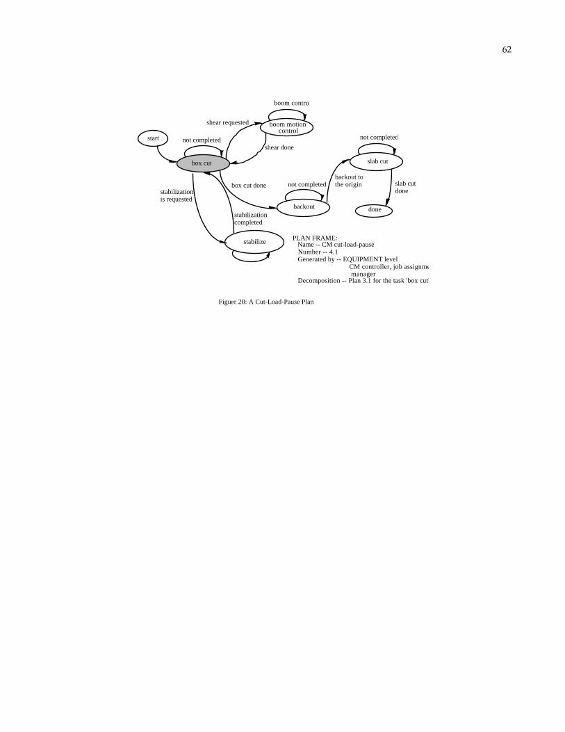
62
not completed
PLAN FRAME: Name -- CM cut-load-pause Number -- 4.1 Generated by -- EQUIPMENT level CM controller, job assignment manager Decomposition -- Plan 3.1 for the task 'box cut'
start
Figure 20: A Cut-Load-Pause Plan
box cut
boom motion control
stabilize
shear requested
stabilization is requested
shear done
boom control
stabilization completed
box cut done not completed
backout
backout to the origin
done
slab cut
not completed
slab cut done
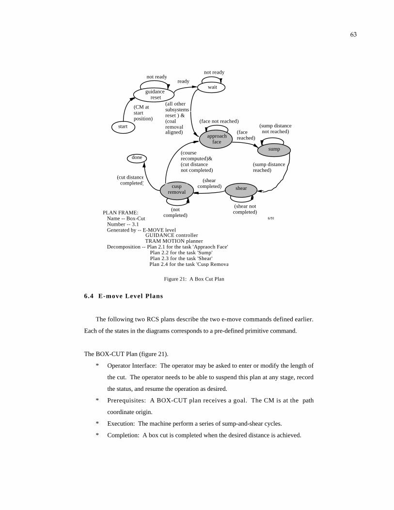
63
start
shearcuspremoval
done
(CM at start position)
approachface
(face not reached)
sump
(sump distancenot reached)
(sump distancereached)
(shear not completed)
(shearcompleted)
(courserecomputed)&(cut distance not completed)
(notcompleted)
(cut distancecompleted)
Figure 21: A Box Cut Plan
ready
not ready
wait
(all othersubsystemsreset ) & (coal removal aligned)
guidance reset
not ready
(facereached)
6/91PLAN FRAME: Name -- Box-Cut Number -- 3.1 Generated by -- E-MOVE level GUIDANCE controller TRAM MOTION planner Decomposition -- Plan 2.1 for the task 'Appraoch Face' Plan 2.2 for the task 'Sump' Plan 2.3 for the task 'Shear' Plan 2.4 for the task 'Cusp Removal'
6.4 E-move Level Plans
The following two RCS plans describe the two e-move commands defined earlier.
Each of the states in the diagrams corresponds to a pre-defined primitive command.
The BOX-CUT Plan (figure 21).
* Operator Interface: The operator may be asked to enter or modify the length of
the cut. The operator needs to be able to suspend this plan at any stage, record
the status, and resume the operation as desired.
* Prerequisites: A BOX-CUT plan receives a goal. The CM is at the path
coordinate origin.
* Execution: The machine perform a series of sump-and-shear cycles.
* Completion: A box cut is completed when the desired distance is achieved.
64
The BACKOUT plan (figure 22).
* Operator Interface: An operator will be asked to enter the error tolerances in the
yaw and the X directions at the beginning of the execution of this command.
He will also be asked to enter a pivot direction and the accompanying pivot
amount when the machine is stuck during the course of tramming backwards.
* Prerequisites: The machine has completed a cusp removal operation, the
stabilization jack has been raised, and the cutter drum has been raised.
* Execution: The basic operation is tramming in reverse. Errors in the X and
yaw directions will be corrected according to the operator specification. As
described above, the operator will be involved in error correction when the
machine gets stuck.
* Completion: The command is executed successfully when the machine is back
to the origin of the path coordinate reference frame.
The NAVIGATE-TO-Zi Plan (figure 23).
* Operator Interface: The operator may be asked to enter or modify the goal
position. The operator needs to be able to suspend this plan when he sees
unexpected obstacles and reenter new goal positions to avoid obstacles.
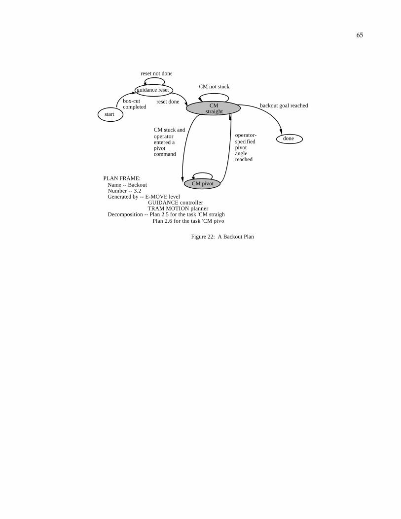
65
start
CM straight
CM pivot
done
box-cut completed
CM stuck and operator entered a pivot command
operator-specified pivot angle reached
CM not stuck
backout goal reached
Figure 22: A Backout Plan
PLAN FRAME: Name -- Backout Number -- 3.2 Generated by -- E-MOVE level GUIDANCE controller TRAM MOTION planner Decomposition -- Plan 2.5 for the task 'CM straight' Plan 2.6 for the task 'CM pivot'
guidance reset
reset done
reset not done
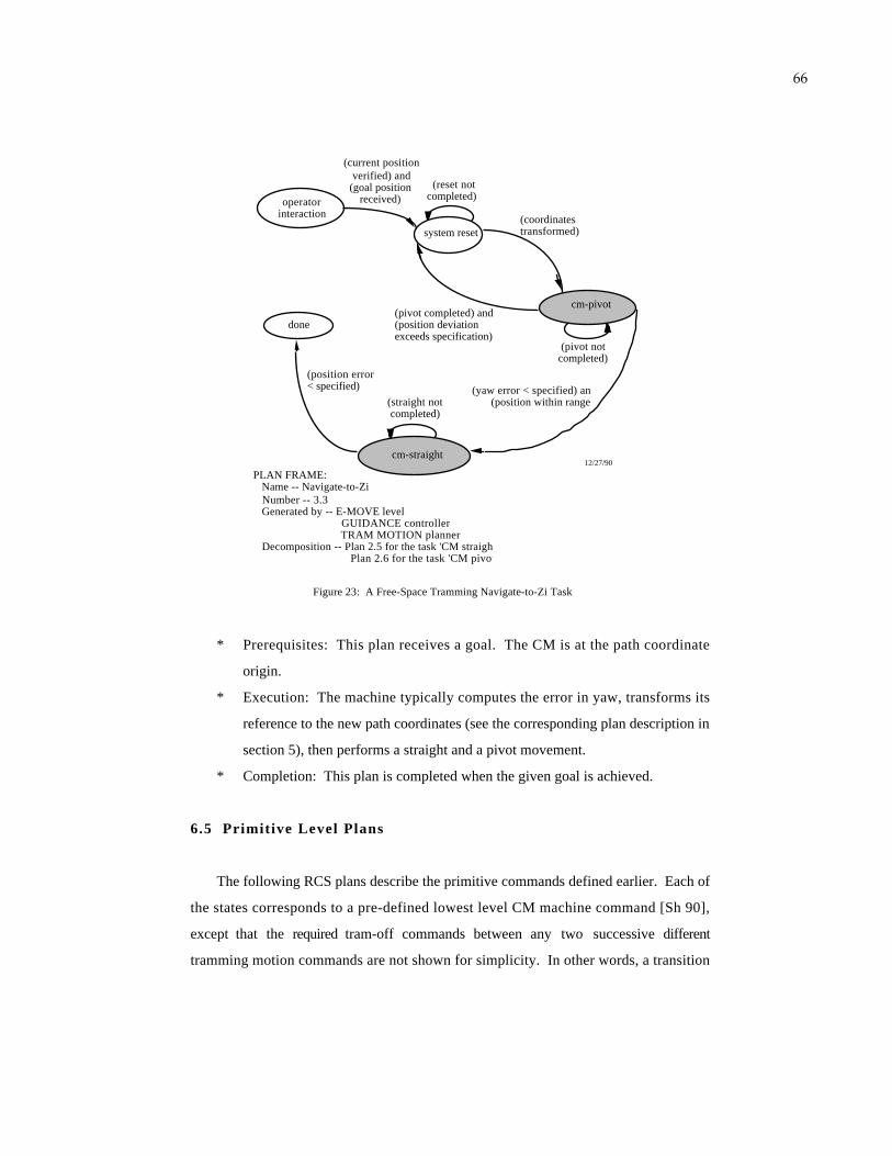
66
operator interaction
system reset
cm-pivot
cm-straight
done
(coordinates transformed)
Figure 23: A Free-Space Tramming Navigate-to-Zi Task
12/27/90
(current position verified) and
(goal position received)
(pivot completed) and(position deviation exceeds specification)
(yaw error < specified) and(position within range)
(position error< specified)
PLAN FRAME: Name -- Navigate-to-Zi Number -- 3.3 Generated by -- E-MOVE level GUIDANCE controller TRAM MOTION planner Decomposition -- Plan 2.5 for the task 'CM straight' Plan 2.6 for the task 'CM pivot'
(reset not completed)
(pivot not completed)
(straight not completed)
* Prerequisites: This plan receives a goal. The CM is at the path coordinate
origin.
* Execution: The machine typically computes the error in yaw, transforms its
reference to the new path coordinates (see the corresponding plan description in
section 5), then performs a straight and a pivot movement.
* Completion: This plan is completed when the given goal is achieved.
6.5 Primitive Level Plans
The following RCS plans describe the primitive commands defined earlier. Each of
the states corresponds to a pre-defined lowest level CM machine command [Sh 90],
except that the required tram-off commands between any two successive different
tramming motion commands are not shown for simplicity. In other words, a transition

67
from a TRAM-FORWARD command to a PIVOT-LEFT command implies a TRAM-
OFF command in between.
Note that the state transition requirements (shown along the edges, or the arrowed
lines) in the following diagrams are described but not specified. The numerical values
for those requirements (for example, the maximum yaw error allowed) should be
computed according to the error control strategy described in section 5.3. These values
may be computed either in advance or on-line in the world model.
The APPROACH-FACE plan (figure 24).
* Operator Interface: The operator will be asked to enter or modify (optionally)
the maximum errors allowed along the yaw and the X axes. Since vehicle
accuracy is crucial to the whole cutting task, the maximum yaw deviation
allowed should be kept as small as feasible.
* Prerequisites: The vehicle guidance controller needs to verify that the machine
is at the origin of the path coordinates before this primitive command can be
executed (see section 5.2 for more detail).
start (CM position at zero)
Figure 24: Approach Face
(Cutter motor current > min. current for cutting) OR
(desired distance achieved)
(yaw deviation withinmaximum allowed)
AND(lateral position deviation
within maximum allowed)
tram forward
pivot left
pivot right
(yaw error >+maximum allowed)
OR(lateral position
deviation out of range and yaw error ref. to
new course is negative)
(yaw deviation withinmaximum allowed)
(yaw error <- maximum allowed) OR(lateral position deviation out of range and yaw error ref. to new course is positive)
(yaw deviation
withinmaximum allowed)
done
jack down
turn off trams
trams off
PLAN FRAME: Name -- Approach-Face Number -- 2.1 Generated by -- PRIMITIVE level TRAM MOTION subsystem TRAM MOTION planner Decomposition -- machine commands
Note: A tram-off command is required between a tram-forward and a pivot.
68
* Execution: Upon verification of its position, the machine will lower the
stabilization jack6 to the floor in order to increase the support to the machine.
The machine will then perform a forward motion along the goal vector to
approach the face. Pivot motion will be required if the yaw deviation gets
larger than the specified limit. In such cases, the forward command will be
stopped and a corrective pivot command will be issued. PIVOT-LEFT and
PIVOT-RIGHT are two distinct states in the diagram. The machine will come
back to the forward motion once the yaw correction is completed and the pivot
command has been stopped. The same corrective activity will also be required
when the lateral deviation exceeds the specified amount. However, in this
situation a revector algorithm will be used first to compute the new goal vector
and the accompanying required amount of yaw correction in order to re-position
the machine toward the goal.
* Completion: This command is completed when either the cutter motor current
exceeds the pre-specified threshold or the desired distance has been achieved.
The SUMP plan (figure 25).
* Operator Interface: The operator will be asked to enter or modify (optionally)
the maximum errors allowed and the sump completion criteria (see the
"completion" factor below).
* Prerequisites: The cutter drum must be at the cutting height, in contact with
the coal, and turning.
6The extent of the use of the jack seems to vary, depending on floor conditions. The authorsassume in this chapter that the floor can be slippery and therefore the jack is to be lowered atthe beginning of the APPROACH-FACE plans, and raised at the end of the SHEAR plan.
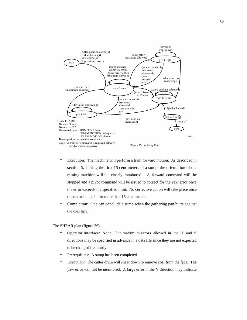
69
start
(cutter position correct)&(CM at the face)&(yaw correct)&(X position correct)
tram forward
tram forward
done
(sump distance within 15 cm)&
(yaw error within maximum allowed)
(yaw error within maximumallowed)&(yaw towards goal)
(sump distance > 15 cm)
(sump goal not achieved)
(goal achieved)
(deviation not improving)
(yaw error > +maximum allowed)
(deviation improving)
(yaw error within maximumallowed)&(yawtowardsgoal)
(yaw error < -maximum allowed)
pivot right
(deviation improving)
(deviation not improving)
turn off trams
trams off
Figure 25: A Sump Plan
3/14/91
PLAN FRAME: Name -- Sump Number -- 2.2 Generated by -- PRIMITIVE level TRAM MOTION subsystem TRAM MOTION planner Decomposition -- machine commands
pivot left
Note: A tram-off command is required between a tram-forward and a pivot.
* Execution: The machine will perform a tram forward motion. As described in
section 5, during the first 15 centimeters of a sump, the orientation of the
mining machine will be closely monitored. A forward command will be
stopped and a pivot command will be issued to correct for the yaw error once
the error exceeds the specified limit. No corrective action will take place once
the drum sumps in for more than 15 centimeters.
* Completion: One can conclude a sump when the gathering pan butts against
the coal face.
The SHEAR plan (figure 26).
* Operator Interface: None. The maximum errors allowed in the X and Y
directions may be specified in advance in a data file since they are not expected
to be changed frequently.
* Prerequisites: A sump has been completed.
* Execution: The cutter drum will shear down to remove coal from the face. The
yaw error will not be monitored. A large error in the Y direction may indicate

70
that the mining machine has been pushed out of the coal face by the counter
reacting force. In such case a tram-forward command will be issued to re-engage
the cutter drum to the face in order to complete the execution of the shear
command. The stabilization jack will be raised after a shear is completed.
start
jack up
(sumpcompleted)
(final shearing angle not reached)&(cutter motor load normal)&(yaw error < maximum allowed)&(position errors < maximum allowed in both x and y directions)
(final shear angle reached)
(cutter motor current too low*)OR
(x, y errors exist and are fairly large <~15 cm>)
(cutter current very high for a certain
period of time) (human intervention)
(position within some bounds of error)
(errors don't increase)
tram forward
done
(jack not up)
turn off trams
trams off
Figure 26: A Shear Plan* May be a sign of CM popping back.
PLAN FRAME: Name -- Shear Number -- 2.3 Generated by -- PRIMITIVE level TRAM MOTION subsystem TRAM MOTION planner Decomposition -- machine commands
wait
* Completion: Generally the cutter drum will shear down to the floor height (see
section 5.6 for other situations). The tram motors will be turned off once a
sump is completed.
The CUSP-REMOVAL plan (figure 27).
* Operator Interface: None.
* Prerequisites: A shear has to be completed.
* Execution: The machine will tram in reverse for a distance equivalent to the
last sump distance without monitoring the yaw error. Cusp left on the floor
from the last sump-and-shear cycle can be removed by the turning cutter drum,
set at the floor height.
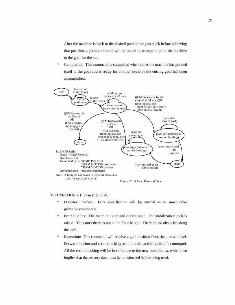
71
After the machine is back to the desired position or gets stuck before achieving
that position, a pivot command will be issued to attempt to point the machine
to the goal for the cut.
* Completion: This command is completed when either the machine has pointed
itself to the goal and is ready for another cycle or the cutting goal has been
accomplished.
start
pivot left (attempt to correct heading)
(yaw toward goal)OR
(timeout)
((CM backwards by 45 cm) OR (CM stuck))&((cutting goal not reached) & (yaw error > + maximum allowed))
(yaw not toward goal)
done
tram reverse(and cusp removal)
(CM not yet backwards 45 cm)
((CM backwards by 45 cm)
OR (CM stuck))&(cutting goal
reached)
done
cutter positioning
(cutter notat the floor)
(cutterat the floor)
pivot right (attempt to correct heading)
(yaw toward goal) OR (timeout)
((CM backwards by 45cm)
OR(CM stuck))&
((cutting goal not reached) & (yaw error < - maximum allowed))
(yaw not toward goal)
Figure 27: A Cusp Removal Plan
PLAN FRAME: Name -- Cusp Removal Number -- 2.4 Generated by -- PRIMITIVE level TRAM MOTION subsystem TRAM MOTION planner Decomposition -- machine commands
Note: A tram-off command is required between a tram-forward and a pivot.
The CM-STRAIGHT plan (figure 28).
* Operator Interface: Error specification will be entered as in most other
primitive commands.
* Prerequisites: The machine is up and operational. The stabilization jack is
raised. The cutter drum is not at the floor height. There are no obstacles along
the path.
* Execution: This command will receive a goal position from the e-move level.
Forward motion and error checking are the main activities in this command.
All the error checking will be in reference to the new coordinates, which also
implies that the sensory data must be transformed before being used.

72
* Completion: This command is completed after the machine reaches the goal
position.
human interaction
(forward/reverse command selected)
(position within goal range)
(yaw deviation withinmaximum allowed)
AND(lateral position deviation
within maximum allowed)
tram forward/reverse
pivot left
pivot right
(yaw error >+maximum allowed)
OR(lateral position
deviation out of range and yaw error ref. to
new course is negative)
(yaw deviation withinmaximum allowed)
(yaw error <- maximum allowed) OR(lateral position deviation out of range and yaw error ref. to new course is positive)
(yaw deviation
withinmaximum allowed)
done
turn off trams
trams off
Figure 28: A CM Straight Plan
PLAN FRAME: Name -- CM-straight Number -- 2.5 Generated by -- PRIMITIVE level TRAM MOTION subsystem TRAM MOTION planner Decomposition -- machine commands
Note: A tram-off command is required between a tram-forward and a pivot.
The CM-PIVOT plan (figure 29).
* Operator Interface: Error specification will be entered as in most other
primitive commands.
* Prerequisites: The machine is up and operational. The stabilization jack is
raised. The cutter drum is not at the floor height. There is no obstacles along
the path.
* Execution: This command will receive a goal position from the e-move level.
Pivot motion and error checking are the main activities in this command.
* Completion: This command is completed after the machine points itself to the
goal.
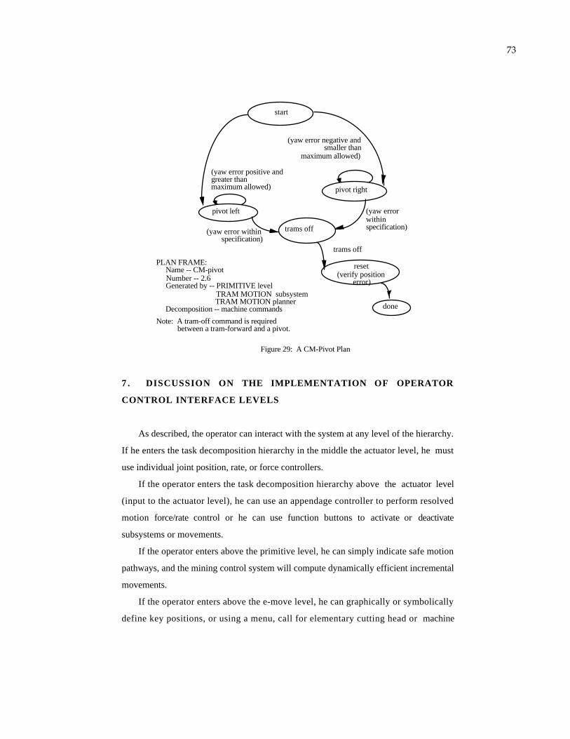
73
pivot left
pivot right
(yaw error positive and greater thanmaximum allowed)
reset(verify position
error)
trams off
trams off
start
(yaw error negative and smaller than
maximum allowed)
(yaw error within specification)
(yaw error within specification)
Figure 29: A CM-Pivot Plan
PLAN FRAME: Name -- CM-pivot Number -- 2.6 Generated by -- PRIMITIVE level TRAM MOTION subsystem TRAM MOTION planner Decomposition -- machine commands
Note: A tram-off command is required between a tram-forward and a pivot.
done
7 . DISCUSSION ON THE IMPLEMENTATION OF OPERATOR
CONTROL INTERFACE LEVELS
As described, the operator can interact with the system at any level of the hierarchy.
If he enters the task decomposition hierarchy in the middle the actuator level, he must
use individual joint position, rate, or force controllers.
If the operator enters the task decomposition hierarchy above the actuator level
(input to the actuator level), he can use an appendage controller to perform resolved
motion force/rate control or he can use function buttons to activate or deactivate
subsystems or movements.
If the operator enters above the primitive level, he can simply indicate safe motion
pathways, and the mining control system will compute dynamically efficient incremental
movements.
If the operator enters above the e-move level, he can graphically or symbolically
define key positions, or using a menu, call for elementary cutting head or machine

74
transport movements (e-moves) such as NAVIGATE-TO-Zi or BOX-CUT. This may be
done using an interactive graphics display with a joystick, mouse, track ball, light pen,
or voice input.
If the operator enters above the equipment level, he can indicate objects and call for
tasks to be done on those objects, such as CM-RESET or CUT-LOAD-PAUSE. This
may be done using cursors and graphic images overlaid on video images.
If the operator enters above the section level, he can reassign mining machines to
different mine sections, insert, monitor, or modify plans that describe equipment task
sequences, define coal preparation, etc.
If the operator enters above the production level, he can re-configure all mining
priorities, change mining requirements, enter or delete jobs, and change the mining
operations schedule.
The operator control interface thus provides mechanisms for entering new
instructions into the various control modules or program selection or execution
sequences. This can be used on-line for real-time supervisory control, or in a background
mode for altering autonomous mining plans before autonomous execution reaches that
part of the plan. The operator control interface can also provide look-ahead simulation of
planned moves so as to analyze the consequences of a prospective motion command
before it is executed.
8 . COMPUTER PROGRAM DESIGN AND IMPLEMENTATION
Computer software for the vehicle guidance has been implemented. Basically each
plan (command) is implemented as an independent software module. The
implementation was done using the C language. State pointers and the switch/case
structure are used to describe the finite state plans. A main program is capable of
executing any tasks (e-move or primitive) selected by an operator. A central command
processor recognizes new motion commands (as opposed to the repetitive ones) as well
as sensory data requests and sends them to the communication node processor. E-move

75
level command reset is achieved by using a single 'task_type' pointer variable for the
commands. This variable may have possible values of 'navigation' or 'cutting.'
Depending on the value, one of the pre-defined data records (storing all the required
information corresponding to that task type) will be selected and used. For example, if
the task_type is 'navigation,' then the reset data record can read:
coal_cutting_subsystem_reset_to_nav
{ switch = off;
drum_angle = default;
jack_position = lifted;}
Details of this implementation can be seen in [Hu 91].
9. SUMMARY
A generic reference model and a task decomposition methodology for the hierarchical
real-time coal mining system control have been presented. The generic reference model,
also referred to as the NIST RCS, comprises intelligent machine units laid out
hierarchically according to their level of responsibility. These intelligent machine units
coordinate according to the pre-defined control flow and information flow models to
perform system tasks.
The task decomposition methodology emphasizes a systematic and generic approach
for developing RCS applications. The iterative system development steps have been
introduced. Each of these steps has associated with it a set of guidelines.
A control hierarchy, a set of task commands, and a vertical swath of RCS plans
have been developed for illustrating the development process. The emphasis has been
placed on the mining machine guidance. The resulting architecture is capable of
receiving a high level coal production command, decomposing it to lower level
commands, and eventually issuing machine actuator commands to achieve the production
goal.

76
This work is by no means complete; many enhancements to this generic model and
the task decomposition methodology will be considered in the future. Ongoing research
at the NIST Robot Systems Division has been focused on the following areas:
* To produce a more comprehensive intelligent machine systems theory.
* To develop more systematic world modeling and sensory processing models.
* To derive a more elaborate system development methodology.
* To investigate software tool environments for the support of RCS system
development, including a generic control module template.
ACKNOWLEDGEMENTS
The authors extend their appreciation to Dr. Christopher Jobes, Dr. George
Schnakenberg, Timothy Matty, and Edward Fries of the U. S. Bureau of Mines for their
insightful input, especially regarding coal mining practice. The authors also extend their
acknowledgement to John Horst and Donald Orser of NIST for their participation in this
project, Neva Carlson and Nicholas Tarnoff for reviewing the manuscript, and Ross
Tabachow for editing this manuscript.

77
REFERENCES
[Al 87] Albus, J. S., et al., "NASA/NBS Standard Reference Model for Telerobot
Control System Architecture (NASREM)," NBS Technical Note 1235, National
Bureau of Standards, U. S. Department of Commerce, July 1987.
[Al 89] Albus, J., et al., "Mining Automation Real-Time Control System Architecture
Standard Reference Model (MASREM)," NIST Technical Note 1261 Volume 1,
National Institute of Standards and Technology, U. S. Department of Commerce,
May 1989.
[An 90] Anderson, D.L., "Laser485.c," Computer Program, Bureau of Mines, 1990.
[As 84] Astrom, K. J. and Wittenmark, B., Computer Controller Systems, Theory and
Design , Prentice-Hall Information and System Sciences Series, Prentice-Hall, Inc.,
Englewood Cliff, N. J., 1984.
[Ba 84] Barbera, A. J., et al., "RCS: The NBS Real-Time Control Systems," Robotics
8 Conference and Exposition, Detroit, MI, June 1984.
[Ba 79] Barbera, A. J., et al., "Hierarchical Control of Robots Using Microcomputers,"
Proceedings of the 9th International Symposium on Industrial Robotics,
Washington, DC, March 1979.
[Bo 76] Box, G. P. and Jenkins G. M., Time Series Analysis, Forecasting and
Control , 1976.
[Bu 68] U. S. Bureau of Mines, A Dictionary of Mining, Minerals, and Related Terms ,
1968.
[Co 91] Coad, P., and Yourdon, E., Object-Oriented Analysis , Yourdon Press
Computing Series, Yourdon Press, Englewood Cliffs, New Jersey, 1991.
78
[Ey 74] Eykhoff, P., System Identification, Parameter and State Estimation , John
Wiley & Sons Ltd., New York, N. Y., 1974.
[Fi 90] Fischer, P. and Daniel, R., "Specification and Design of Input Devices for
Teleoperation," Proceedings of the 1990 IEEE International Conference on Robotics
and Automation, Cincinnati, Ohio, May 1990.
[Ho 90-1] Horst, J. A., "An Application of Measurement Error Propagation Theory to
Two Measurement Systems Used to Calculate the Position and Heading of a Vehicle
on a Flat Surface," NIST Interagency Report NISTIR 90-4434, National Institute of
Standards and Technology, U. S. Department of Commerce, 1990.
[Ho 90-2] Horst, J. A., "John Horst's Phone Conversation of March 23, 1990 with Tim
Matty, a CM 'Expert' at BOM PRC," Telephone Conversation Notes, March, 1990.
[Hu 91] Huang, H., et al., "A Motion Control Algorithm for a Continuous Mining
Machine Based on a Hierarchical Real-Time Control System Design Methodology,"
Journal of Intelligent and Robotic Systems, in process, Kluwer academic publishers,
Dordrecht, The Netherlands, 1991.
[Hu 90-1] Huang, H., "A Hierarchical Real-Time Control System for Use with Coal
Mining Automation," Fourth Conference on the Use of Computers in the Coal
Industry, the West Virginia University, Morgantown, West Virginia, June 1990.
[Hu 90-2] Huang, H., "Hierarchical Real-Time Control Task Decomposition for a Coal
Mining Automation Project," NIST Interagency Report NISTIR 90-4271, National
Institute of Standards and Technology, U. S. Department of Commerce, March,
1990.
[Hu 90-3] Huang, H. and Quintero, R., "Task Decomposition Methodology for the
Design of a Coal Mining Automation Hierarchical Real-Time Control System,"

79
The Fifth IEEE International Symposium on Intelligent Control, Philadelphia, PA,
September 5 - 7, 1990.
[Hu 82] Huang, H., "Suppressing the Nonstationary Portion of the Transient Response
in Digital Simulation," Master's Thesis, The University of Texas at Arlington,
Arlington, Texas, 1982.
[Jo 82] Joy Machinery Company, Technical Service Manual, Joy 16CM Miner , 1982.
[Li] A. D. Little, Inc., "A Theoretical Mathematic Analysis of Turning Capability of
Full Faced Continuous Mining Machines," Notes Obtained from Schnakenberg, G.,
U. S. Bureau of Mines.
[Mi 89] Michell, J., "Diagnostic Maintenance Expert System for the Hydraulic
Subsystem of a Continuous Miner," IEEE Transactions on Industry Applications,
Vol. 25, No. 5, September/October 1989.
[No 88] North, R. A. and Riley V. A., "W/INDEX: A Predictive Model of Operator
Workload," NATO AGARD Symposium, Orlando, Florida, 1988.
[Sa 89] Samet, H., The Design and Analysis of Spatial Data Structures , Addison-
Wesley Publishing Company, Inc., New York, New York, 1990.
[Sc 89] Schnakenberg, G., "Underground Coal Mining Automation Research (Room
and Pillar Mining) Justification and Research Program Plan," Ver. 1.1, Bureau of
Mines, United States Department of the Interior, August 24, 1989.
[Sc 90] Schnakenberg, G. and Sammarco, J., "Joy 14CM Machine Test Data," U. S.
Bureau of Mines Internal Document, September 28, 1990.
80
[Sh 90] Schiffbaur W. H., et al., "Computer Network for Continuous Mining Machine
(Joy 14CM) Control -- Documentation of Node Functions and Communications,"
U. S. Bureau of Mines Internal Document, April 1990.
[St 83] Stefanko, R., Coal Mining Technology, Theory and Practice , Society of
Mining Engineers of the American Institute of Mining, Metallurgical, and
Petroleum Engineers, Inc., New York, New York, 1983.
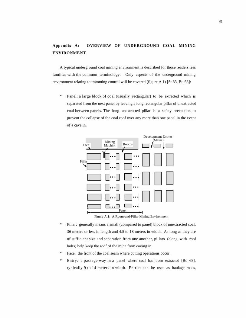
81
Appendix A: OVERVIEW OF UNDERGROUND COAL MINING
ENVIRONMENT
A typical underground coal mining environment is described for those readers less
familiar with the common terminology. Only aspects of the underground mining
environment relating to tramming control will be covered (figure A.1) [St 83, Bu 68]:
* Panel: a large block of coal (usually rectangular) to be extracted which is
separated from the next panel by leaving a long rectangular pillar of unextracted
coal between panels. The long unextracted pillar is a safety precaution to
prevent the collapse of the coal roof over any more than one panel in the event
of a cave in.
Figure A.1: A Room-and-Pillar Mining Environment
Development Entries(Mains)
Pillar
RoomsMiningMachine
...
...
...
...
...
...
Face
...
...
...
...
...
...Panel
* Pillar: generally means a small (compared to panel) block of unextracted coal,
36 meters or less in length and 4.5 to 18 meters in width. As long as they are
of sufficient size and separation from one another, pillars (along with roof
bolts) help keep the roof of the mine from caving in.
* Face: the front of the coal seam where cutting operations occur.
* Entry: a passage way in a panel where coal has been extracted [Bu 68],
typically 9 to 14 meters in width. Entries can be used as haulage roads,

82
transportation roads, or ventilation paths. Entries are formed by removing coal
and leaving pillars that are nominally rectangular in shape.
* Cut: The action that the mining machine takes to excavate a block of coal (see
[Hu 91] for a discussion on the size of a cut). Usually the mining machine cuts
in two passes to achieve a desired width of a cut (typically the width of an
entry). The first pass may be referred to as a box-cut, and the second pass may
be referred to as a slab-cut.
* Room-and-Pillar Mining: a mining method that also features the development
of main entries at both sides of a panel. Coal is extracted forming rooms [St
83] with pillars left. Pillars may be extracted at a later stage in a retracting
operation. Sizes of pillars and width of entries may vary depending on the roof
support and the transportation support requirements.

83
Appendix B: THE JOY 14CM CONTINUOUS MINER
Continuous mining machines (see figure B.1) are used in room-and-pillar mining.
The major components of a Joy 14CM continuous miner (CM) of concern include
(figure B.1):
gathering head
tread sets
cutter drum
conveyor boom
stabilization jack
conveyor belt
Figure B.1: The Major Components of a Continuous Miner
35' (approximately)10
' (ap
prox
imat
ely)
* A Tramming Subsystem: A tram motor driving a tread set exists on both sides
of the machine. Generally, the motion of the CM's is referred to as
"tramming," (e.g., tram-forward, tram-reverse) and the control of the machine
motion can be referred to as "tram control."
* A Cutter Drum: A hydraulic actuated cutter boom extends out at the front of
the machine. Attached to the front of the boom is an electrically operated cutter
drum. Replaceable cutting bits are installed at the surface of the cutter drum
which fracture the coal as the drum is pushed into the coal face while turning.
* A Gathering Head Subsystem: This subsystem is located at the bottom of the
front end of the machine. A gathering pan can be set to float on the floor. The
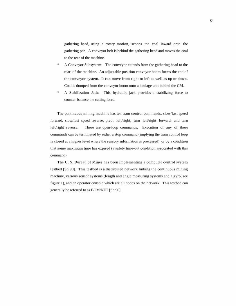
84
gathering head, using a rotary motion, scoops the coal inward onto the
gathering pan. A conveyor belt is behind the gathering head and moves the coal
to the rear of the machine.
* A Conveyor Subsystem: The conveyor extends from the gathering head to the
rear of the machine. An adjustable position conveyor boom forms the end of
the conveyor system. It can move from right to left as well as up or down.
Coal is dumped from the conveyor boom onto a haulage unit behind the CM.
* A Stabilization Jack: This hydraulic jack provides a stabilizing force to
counter-balance the cutting force.
The continuous mining machine has ten tram control commands: slow/fast speed
forward, slow/fast speed reverse, pivot left/right, turn left/right forward, and turn
left/right reverse. These are open-loop commands. Execution of any of these
commands can be terminated by either a stop command (implying the tram control loop
is closed at a higher level where the sensory information is processed), or by a condition
that some maximum time has expired (a safety time-out condition associated with this
command).
The U. S. Bureau of Mines has been implementing a computer control system
testbed [Sh 90]. This testbed is a distributed network linking the continuous mining
machine, various sensor systems (length and angle measuring systems and a gyro, see
figure 1), and an operator console which are all nodes on the network. This testbed can
generally be referred to as BOM/NET [Sh 90].