a rbk - uriel-shay.comžנתקי שליפה... · - thermal current of fuse switch disconnector...
TRANSCRIPT

aK
ceSO
ria
PB
S
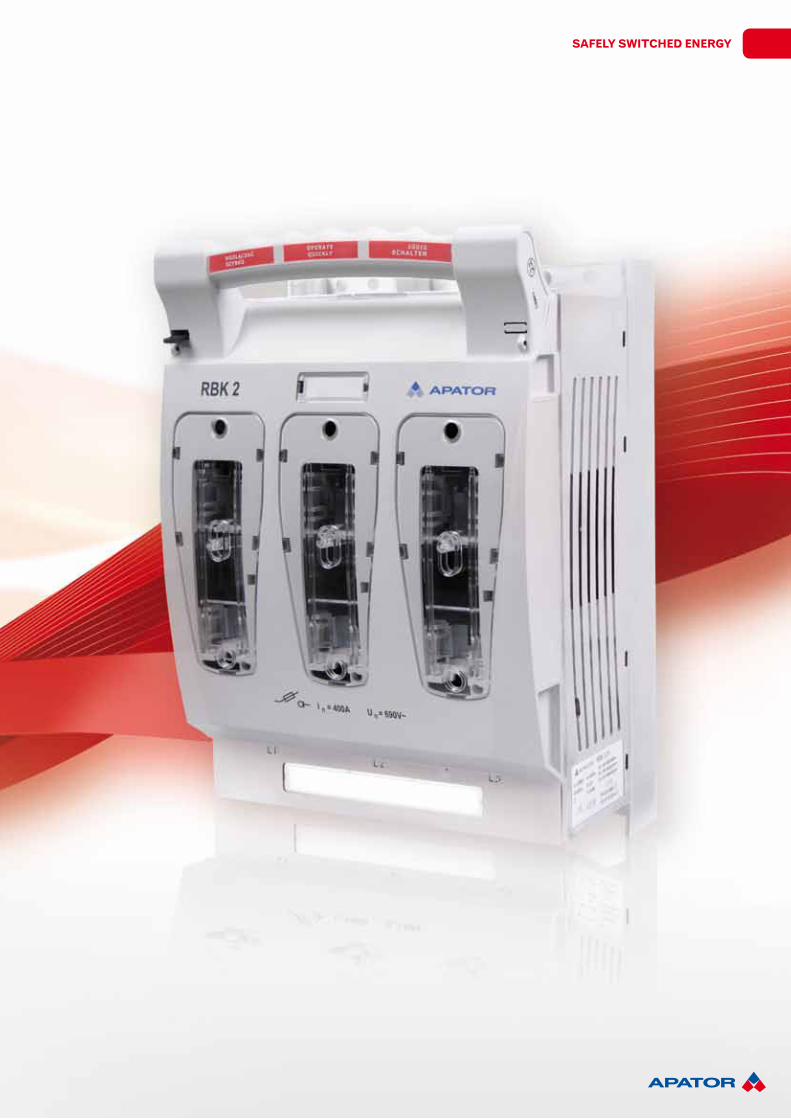
RBKfuse switch disconnectors
rBK fuse switch disconnectors are designed for distribution of electricity and protection of electrical equipment against short-circuits and overloads with industrial fuse links.
Switchgear
Safely Switched energy
46
Switchgear
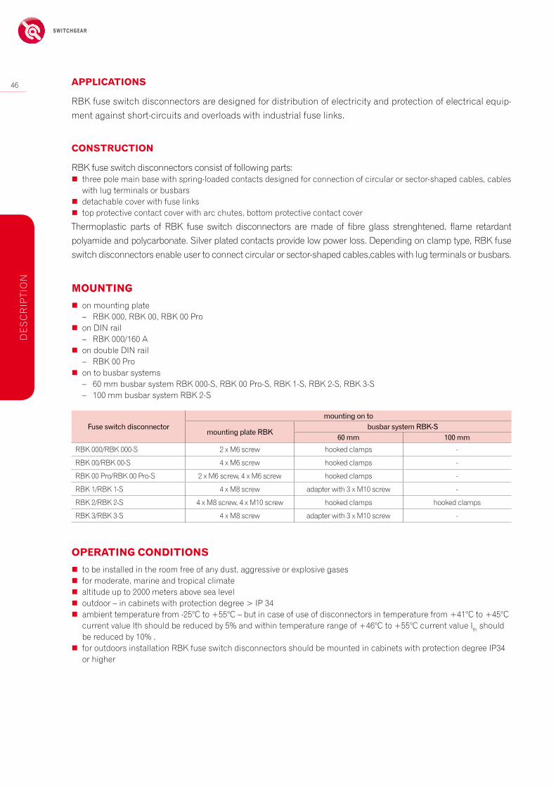
cOnStrUctiOn
rBK fuse switch disconnectors consist of following parts: � three pole main base with spring-loaded contacts designed for connection of circular or sector-shaped cables, cables
with lug terminals or busbars � detachable cover with fuse links � top protective contact cover with arc chutes, bottom protective contact cover
thermoplastic parts of rBK fuse switch disconnectors are made of fibre glass strenghtened, flame retardant polyamide and polycarbonate. Silver plated contacts provide low power loss. Depending on clamp type, rBK fuse switch disconnectors enable user to connect circular or sector-shaped cables,cables with lug terminals or busbars.
46
aPPlicatiOnS
rBK fuse switch disconnectors are designed for distribution of electricity and protection of electrical equip-ment against short-circuits and overloads with industrial fuse links.
MOUnting � on mounting plate
– rBK 000, rBK 00, rBK 00 Pro � on DiN rail
– rBK 000/160 a � on double DiN rail
– rBK 00 Pro � on to busbar systems
– 60 mm busbar system rBK 000-S, rBK 00 Pro-S, rBK 1-S, rBK 2-S, rBK 3-S – 100 mm busbar system rBK 2-S
De
Sc
riP
tiO
N
Fuseswitchdisconnectormountingonto
mountingplateRBKbusbarsystemRBK-S
60mm 100mm
rBK 000/rBK 000-S 2 x M6 screw hooked clamps -
rBK 00/rBK 00-S 4 x M6 screw hooked clamps -
rBK 00 Pro/rBK 00 Pro-S 2 x M6 screw, 4 x M6 screw hooked clamps -
rBK 1/rBK 1-S 4 x M8 screw adapter with 3 x M10 screw -
rBK 2/rBK 2-S 4 x M8 screw, 4 x M10 screw hooked clamps hooked clamps
rBK 3/rBK 3-S 4 x M8 screw adapter with 3 x M10 screw -
OPerating cOnditiOnS � to be installed in the room free of any dust, aggressive or explosive gases � for moderate, marine and tropical climate � altitude up to 2000 meters above sea level � outdoor – in cabinets with protection degree > iP 34 � ambient temperature from -25°c to +55°c – but in case of use of disconnectors in temperature from +41°c to +45°c
current value ith should be reduced by 5% and within temperature range of +46°c to +55°c current value ith should be reduced by 10% ,
� for outdoors installation rBK fuse switch disconnectors should be mounted in cabinets with protection degree iP34 or higher
Safely Switched energy
47cOnfOrMity with StandardS
PN-eN 60947-1 PN-eN 60947-3 PN-hD 60269-2
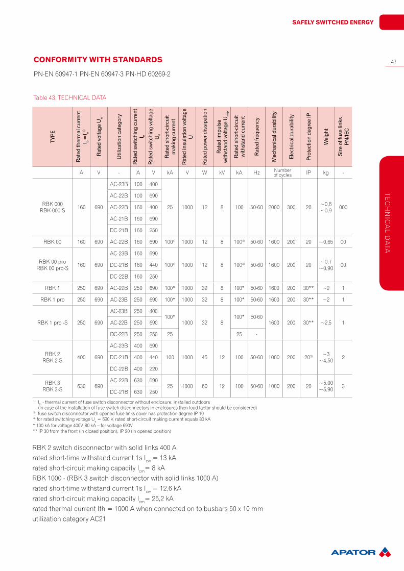
table 43. techNicaL Data
rBK 2 switch disconnector with solid links 400 arated short-time withstand current 1s icw = 13 karated short-circuit making capacity icm= 8 karBK 1000 - (rBK 3 switch disconnector with solid links 1000 a)rated short-time withstand current 1s icw = 12,6 karated short-circuit making capacity icm= 25,2 karated thermal current ith = 1000 a when connected on to busbars 50 x 10 mmutilization category ac21
1) ith - thermal current of fuse switch disconnector without enclosure, installed outdoors (in case of the installation of fuse switch disconnectors in enclosures then load factor should be considered)3) fuse switch disconnector with opened fuse links cover has protection degree iP 104) for rated switching voltage ue = 690 V, rated short-circuit making current equals 80 ka
tec
hN
ica
L Da
ta
TYPE
Ratedthermalcurrent
I th=I n1)
RatedvoltageUn
Utilizationcategory
Ratedswitchingcurrent
I eRatedswitchingvoltage
Ue
Ratedshort-circuit
makingcurrent
Ratedinsulationvoltage
Ui
Ratedpowerdissipation
Ratedimpulse
withstandvoltageUimp.
Ratedshort-circuit
withstandcurrent
Ratedfrequency
Mechanicaldurability
Electricaldurability
ProtectiondegreeIP
Weight
Sizeoffuselinks
PN/IEC
a V - a V ka V w kV ka hz Number of cycles iP kg -
rBK 000rBK 000-S 160 690
ac-23B 100 400
25 1000 12 8 100 50-60 2000 300 20 ~0,6~0,9 000
ac-22B 100 690
ac-22B 160 400
ac-21B 160 690
Dc-21B 160 250
rBK 00 160 690 ac-22B 160 690 1004) 1000 12 8 1004) 50-60 1600 200 20 ~0,65 00
rBK 00 prorBK 00 pro-S 160 690
ac-23B 160 690
1004) 1000 12 8 1004) 50-60 1600 200 20 ~0,7~0,90 00Dc-21B 160 440
Dc-22B 160 250
rBK 1 250 690 ac-22B 250 690 100* 1000 32 8 100* 50-60 1600 200 30** ~2 1
rBK 1 pro 250 690 ac-23B 250 690 100* 1000 32 8 100* 50-60 1600 200 30** ~2 1
rBK 1 pro -S 250 690
ac-23B 250 400100*
1000 32 8100* 50-60
1600 200 30** ~2,5 1ac-22B 250 690
Dc-22B 250 250 25 25 -
rBK 2rBK 2-S 400 690
ac-23B 400 690
100 1000 45 12 100 50-60 1000 200 203) ~3~4,50 2Dc-21B 400 440
Dc-22B 400 220
rBK 3rBK 3-S 630 690
ac-22B 630 69025 1000 60 12 100 50-60 1000 200 20 ~5,00
~5,90 3Dc-21B 630 250
* 100 ka for voltage 400V, 80 ka – for voltage 690V** iP 30 from the front (in closed position), iP 20 (in opened position)

48
Switchgear
rBK 000for installation
on mounting plate
RBK000/160A Cableterminal ArticleNo.
rBK 000 for connection of cables with bare ends S-bridge clamps 63-823191-011
rBK 000-e for connection of cables with bare ends,for mounting on DiN rail, S-bridge clamps 63-823191-051
rBK 000-O for connection of cables with bare ends, cable terminal shrouds S-bridge clamps on request*
rBK 000-e-O or connection of cables with bare ends, for mounting on DiN rail,cable terminal shrouds S-bridge clamps on request*
rBK 000-w for connection of cables with bare ends, lenghtened cable terminal shrouds S-bridge clamps 63-823191-071
rBK 000-SD for installation on to 60 mm busbar system, bottom cable terminal connection S-bridge clamps 63-823234-031
rBK 000-Sg for installation on to 60 mm busbar system, top cable terminal connection S-bridge clamps 63-823234-011
rBK 000-SD-M for installation on to 60 mm busbar system, bottom cable terminal connection screw terminal M8 63-823234-041
rBK 000-Sg-M for installation on to 60 mm busbar system , top cable terminal connection screw terminal M8 63-823234-021
rBK 000-M for connection of cables with lug terminals screw terminal M8 63-823191-021
rBK 000-M-e for connection of cables with lug terminals, for mounting on DiN rail, screw terminal M8 63-823191-061
rBK 000-M-O for connection of cables with lug terminals, cable terminal shrouds screw terminal M8 on request*
rBK 000-M-e-O for connection of cables with lug terminals, for mounting on DiN rail,cable terminal shrouds screw terminal M8 on request*
rBK 000-w-M for connection of cables with lug terminals, lenghtened cable terminal shrouds screw terminal M8 63-823191-081
table 44. techNicaL Data
rB
K 0
00
Parameters RBK000
rated thermal current ith = in a 160
rated voltage un V 690
utilization category - ac-23B ac-22B ac-22B ac-21B Dc-21B
rated switching voltage ue V 400 690 400 690 250
rated switching current ie a 100 100 160 160 160
rated short circuit making current ka 25
rated short circuit withstand current ka 100
rated insulation voltage ui V 1000
rated impulse withstand voltage uimp kV 8
rated power dissipation w 12
rated frequency hz 50-60
Mechanical durability Number of cycles
2000
electrical durability 300
Protection degree iP iP 20
Size of fuse links 000
accessories on page 70
table 45. VerSiONS
rBk 000 (160 a, 690 V)
* on customer’s request, time of delivery: 2 weeks eXw torun, Poland, incoterms 2000
Safely Switched energy
49
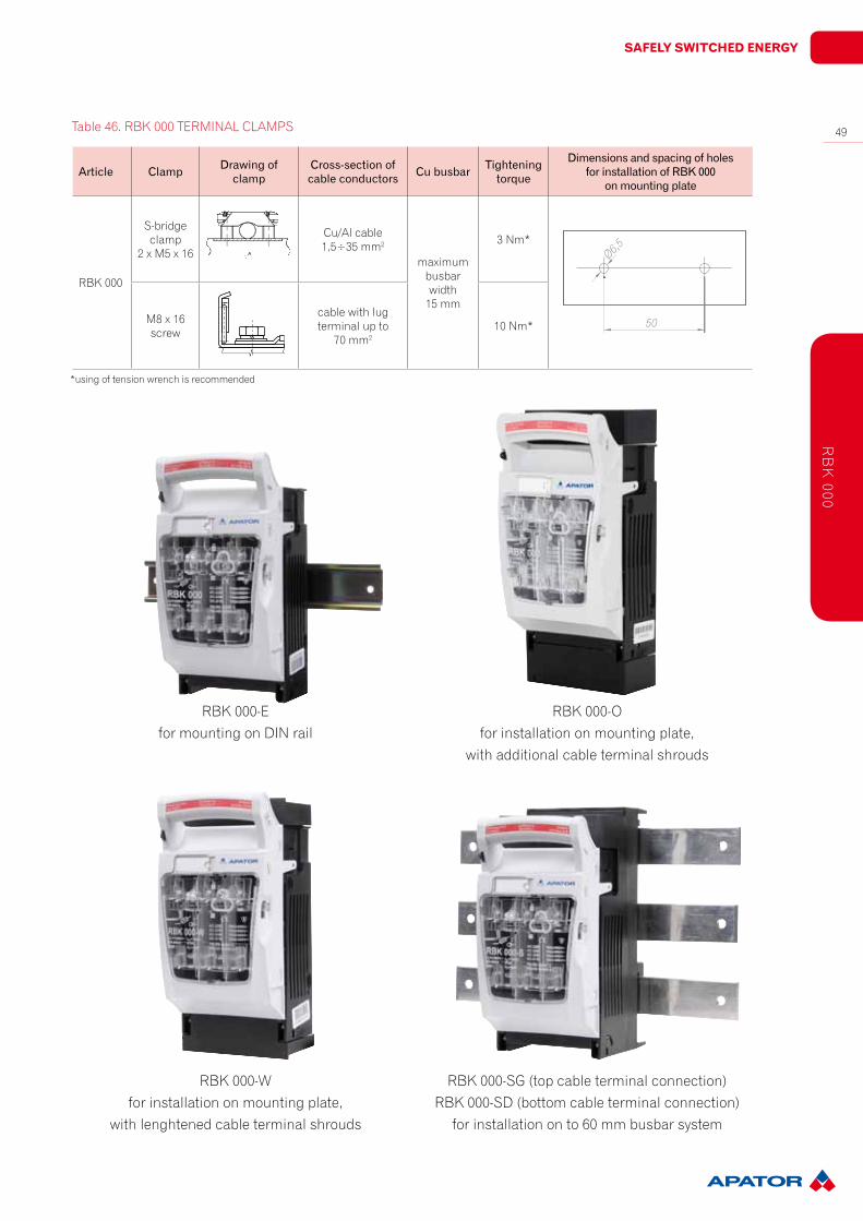
rBK 000-Sg (top cable terminal connection)rBK 000-SD (bottom cable terminal connection)
for installation on to 60 mm busbar system
Article Clamp Drawingofclamp
Cross-sectionofcableconductors Cubusbar Tightening
torque
DimensionsandspacingofholesforinstallationofRBK000onmountingplate
rBK 000
S-bridge clamp
2 x M5 x 16
cu/al cable1,5÷35 mm2
maximum busbarwidth
15 mm
3 Nm*
M8 x 16 screw
cable with lugterminal up to
70 mm210 Nm*
*using of tension wrench is recommended
table 46. rBK 000 terMiNaL cLaMPS
Ø6,5
50
rB
K 000
rBK 000-efor mounting on DiN rail
rBK 000-Ofor installation on mounting plate,
with additional cable terminal shrouds
rBK 000-wfor installation on mounting plate,
with lenghtened cable terminal shrouds
50
Switchgear
Article Clamp Drawingofclamp
Cross-sectionofcableconductors Cubusbar Tightening
torque
DimensionsandspacingofholesforinstallationofRBK00on
mountingplate
rBK 00
S-bridge clamp
2 x M5 x 16
cu/al cable4÷50 mm2
maximum busbarwidth
20 mm
3 Nm*
M8 x 16 screw
cable with lugterminal up to 70 mm2 10 Nm*
V-shaped clamp
2 x M5 x 203 Nm*
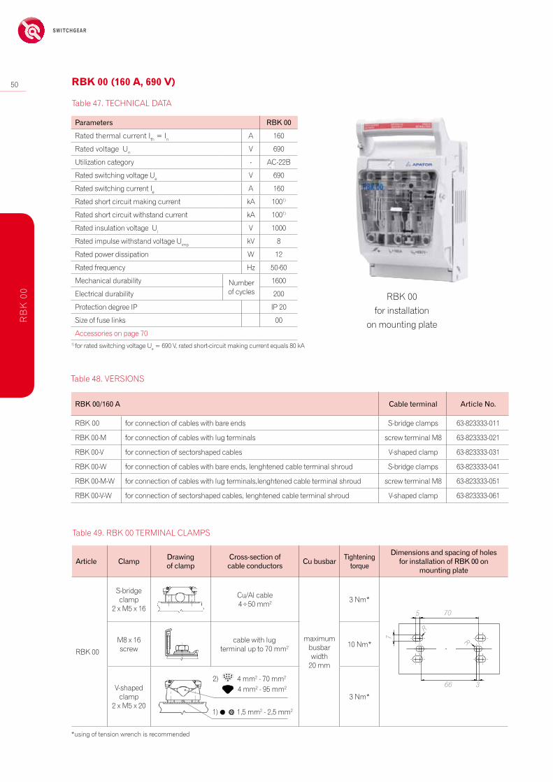
rBK 00for installation
on mounting plate
RBK00/160A Cableterminal ArticleNo.
rBK 00 for connection of cables with bare ends S-bridge clamps 63-823333-011
rBK 00-M for connection of cables with lug terminals screw terminal M8 63-823333-021
rBK 00-V for connection of sectorshaped cables V-shaped clamp 63-823333-031
rBK 00-w for connection of cables with bare ends, lenghtened cable terminal shroud S-bridge clamps 63-823333-041
rBK 00-M-w for connection of cables with lug terminals,lenghtened cable terminal shroud screw terminal M8 63-823333-051
rBK 00-V-w for connection of sectorshaped cables, lenghtened cable terminal shroud V-shaped clamp 63-823333-061
table 47. techNicaL Data
table 48. VerSiONS
*using of tension wrench is recommended
1) 1,5 mm2 - 2,5 mm2
2) 4 mm2 - 70 mm2 4 mm2 - 95 mm2
rB
K 0
0
table 49. rBK 00 terMiNaL cLaMPS
rBk 00 (160 a, 690 V)
Parameters RBK00
rated thermal current ith = in a 160
rated voltage un V 690
utilization category - ac-22B
rated switching voltage ue V 690
rated switching current ie a 160
rated short circuit making current ka 1001)
rated short circuit withstand current ka 1001)
rated insulation voltage ui V 1000
rated impulse withstand voltage uimp kV 8
rated power dissipation w 12
rated frequency hz 50-60
Mechanical durability Number of cycles
1600
electrical durability 200
Protection degree iP iP 20
Size of fuse links 00
accessories on page 701) for rated switching voltage ue = 690 V, rated short-circuit making current equals 80 ka
R
5 70
R
66 3
7
Safely Switched energy
51
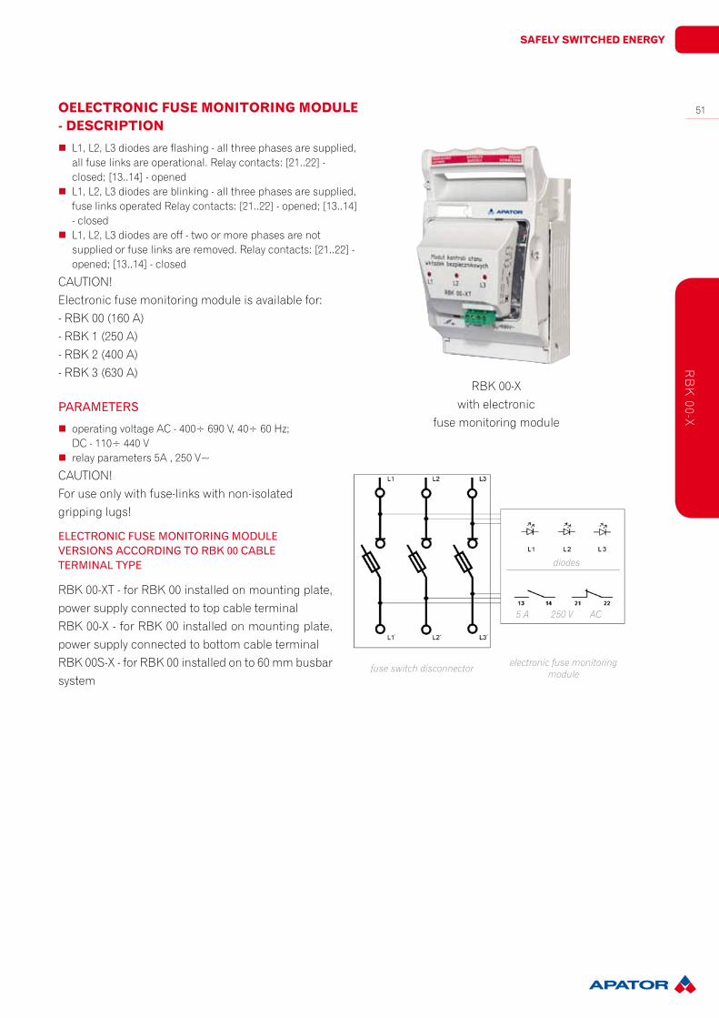
rBK 00-Xwith electronic
fuse monitoring module
OelectrOnic fUSe MOnitOring MOdUle - deScriPtiOn
� L1, L2, L3 diodes are flashing - all three phases are supplied, all fuse links are operational. relay contacts: [21..22] - closed; [13..14] - opened
� L1, L2, L3 diodes are blinking - all three phases are supplied, fuse links operated relay contacts: [21..22] - opened; [13..14] - closed
� L1, L2, L3 diodes are off - two or more phases are not supplied or fuse links are removed. relay contacts: [21..22] - opened; [13..14] - closed
cautiON!electronic fuse monitoring module is available for:- rBK 00 (160 a)- rBK 1 (250 a)- rBK 2 (400 a)- rBK 3 (630 a)
PARAMETERS
� operating voltage ac - 400÷ 690 V, 40÷ 60 hz; Dc - 110÷ 440 V
� relay parameters 5a , 250 V~
cautiON!For use only with fuse-links with non-isolated gripping lugs!
ELECTRONICFUSEMONITORINGMODULEVERSIONSACCORDINGTORBK00CABLETERMINALTYPE
rBK 00-Xt - for rBK 00 installed on mounting plate, power supply connected to top cable terminalrBK 00-X - for rBK 00 installed on mounting plate, power supply connected to bottom cable terminalrBK 00S-X - for rBK 00 installed on to 60 mm busbar system
5 A 250 V AC
fuse switch disconnector electronic fuse monitoring module
diodes
rB
K 00-X

52
Switchgear
RBK00pro/160A Cableterminal ArticleNo.
rBK 00 pro for connection of cables with bare ends S-bridge clamps 63-823256-011
rBK 00 pro-M for connection of cables with lug terminals screw terminal M8 63-823256-021
rBK 00 pro-V for connection of sectorshaped cables V-shaped clamp 63-823256-031
rBK 00 pro-w for connection of cables with bare ends, lenghtened cable terminal shroud S-bridge clamps 63-823256-041
rBK 00 pro-M-w for connection of cables with lug terminals, lenghtened cable terminal shroud screw terminal M8 63-823256-051
rBK 00 pro-V-w for connection of sectorshaped cables, lenghtened cable terminal shroud V-shaped clamp 63-823256-061
rBK 00 pro-O for connection of cables with bare ends, cable terminal shrouds S-bridge clamps on request*
rBK 00 pro-w-O for connection of cables with bare ends, lenghtened cable terminal shrouds, cable terminal shrouds S-bridge clamps on request*
rBK 00 pro-Sg for installation on to 60 mm busbar system, top cable terminal connection S-bridge clamps 63-823259-011
rBK 00 pro-Sg-M for installation on to 60 mm busbar system, top cable terminal connection screw terminal M8 63-823259-021
rBK 00 pro-Sg-V for installation on to 60 mm busbar system, top cable terminal connection V-shaped clamp 63-823259-051
rBK 00 pro-SD for installation on to 60 mm busbar system, bottom cable terminal connection S-bridge clamps 63-823259-031
rBK 00 pro-SD-M for installation on to 60 mm busbar system, bottom cable terminal connection screw terminal M8 63-823259-041
rBK 00 pro-SD-V for installation on to 60 mm busbar system, bottom cable terminal connection V-shaped clamp 63-823259-061
rBK 00 pro-e-125mm for mounting on double DiN rail with spacing of 125 mm
S-bridge clampsscrew terminal M8
V-shaped clampon request*
rBK 00 pro-e-150mm for mounting on double DiN rail with spacing of 150 mm
S-bridge clampsscrew terminal M8
V-shaped clampon request*
rBK 00 pro
table 50. techNicaL Data
rB
K 0
0 pr
o
table 51. VerSiONS
rBk 00 PrO (160 a, 690 V)
* on customer’s request, time of delivery: 2 weeks eXw torun, Poland, incoterms 2000
Parameters RBK00pro
rated thermal current ith = in a 160
rated voltage un V 690
utilization category - ac-23B Dc-22B Dc-21B
rated switching voltage ue V 690 250 440
rated switching current ie a 160 160 160
rated short circuit making current ka 1001)
rated short circuit withstand current ka 1001)
rated insulation voltage ui V 1000
rated impulse withstand voltage uimp kV 8
rated power dissipation w 12
rated frequency hz 50-60
Mechanical durability Number of cycles
1600
lectrical durability 200
Stopień ochrony iP 20
Protection degree iP 00
accessories on page 701) for rated switching voltage ue = 690 V, rated short-circuit making current equals 80 ka

Safely Switched energy
53
rB
K 00 pro
Article Clamp Drawingofclamp
Cross-sectionofcableconductors
Cubusbar
Tighteningtorque
DimensionsandspacingofholesforinstallationofRBK00on
mountingplate
rBK 00pro
S-bridge clamp
2 x M5 x 16
cu/al cable4 ÷ 50 mm2
maxi-mum
busbarwidth
20 mm
3 Nm*
M8 x 16 screw
cable with lugterminal up to 70 mm2 10 Nm*
V-shaped clamp
2 x M5 x 203 Nm*
table 52. rBK 00 terMiNaL cLaMPS
*using of tension wrench is recommended
R
5 70
R
66 3
7
1) 1,5 mm2 - 2,5 mm2
2) 4 mm2 - 70 mm2 4 mm2 - 95 mm2
rBK 00 pro-S rBK 00 pro-w
54
Switchgearr
BK
1
rBk 1 (250 a, 690 V)
table 53. techNicaL Data
Parameters RBK1 RBK1pro RBK1pro-S
rated thermal current ith = in a 250 250 250
rated voltage un V 690 690 690
utilization category - ac-22B ac-23B ac-23B ac-22B Dc-22B
rated switching voltage ue V 690 690 400 690 250
rated switching current ie a 250 250 250
rated short circuit making current ka 100* 100* 100* 25
rated short circuit withstand current ka 100* 100* 100* 25
Znamionowe napięcie izolacji ui V 1000 1000 1000
rated impulse withstand voltage uimp kV 8 8 8
rated power dissipation w 32 32 32
rated frequency hz 50-60 50-60 50-60 -
Mechanical durability Number of cycles
1600 1600 1600
electrical durability 200 200 200
Protection degree iP - 30** 30** 30**
Size of fuse links - 1 1 1
weight kg ~2 ~2 ~2,5
accessories on page 70
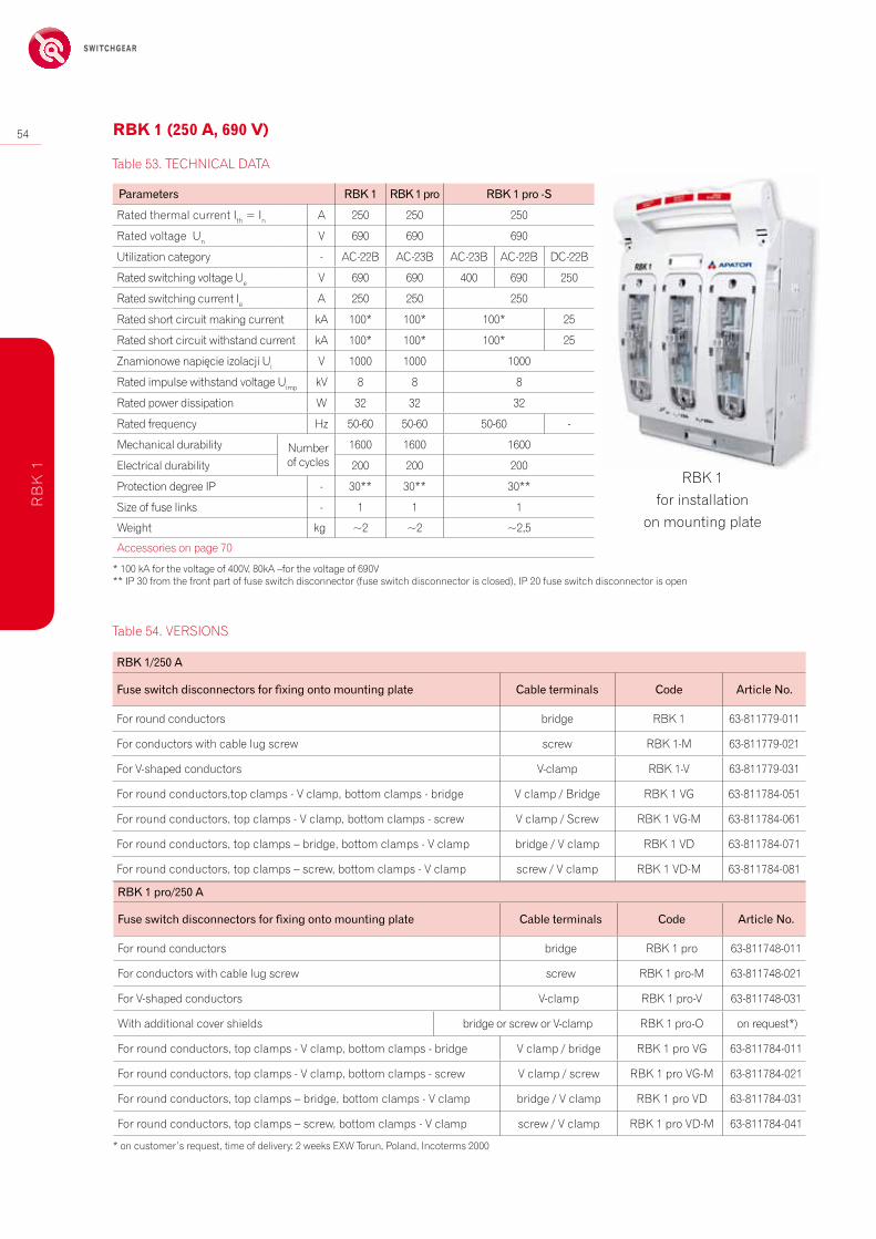
rBK 1for installation
on mounting plate
table 54. VerSiONS
RBK1/250A
Fuseswitchdisconnectorsforfixingontomountingplate Cableterminals Code ArticleNo.
For round conductors bridge rBK 1 63-811779-011
For conductors with cable lug screw screw rBK 1-M 63-811779-021
For V-shaped conductors V-clamp rBK 1-V 63-811779-031
For round conductors,top clamps - V clamp, bottom clamps - bridge V clamp / Bridge rBK 1 Vg 63-811784-051
For round conductors, top clamps - V clamp, bottom clamps - screw V clamp / Screw rBK 1 Vg-M 63-811784-061
For round conductors, top clamps – bridge, bottom clamps - V clamp bridge / V clamp rBK 1 VD 63-811784-071
For round conductors, top clamps – screw, bottom clamps - V clamp screw / V clamp rBK 1 VD-M 63-811784-081
* 100 ka for the voltage of 400V, 80ka –for the voltage of 690V** iP 30 from the front part of fuse switch disconnector (fuse switch disconnector is closed), iP 20 fuse switch disconnector is open
RBK1pro/250A
Fuseswitchdisconnectorsforfixingontomountingplate Cableterminals Code ArticleNo.
For round conductors bridge rBK 1 pro 63-811748-011
For conductors with cable lug screw screw rBK 1 pro-M 63-811748-021
For V-shaped conductors V-clamp rBK 1 pro-V 63-811748-031
with additional cover shields bridge or screw or V-clamp rBK 1 pro-O on request*)
For round conductors, top clamps - V clamp, bottom clamps - bridge V clamp / bridge rBK 1 pro Vg 63-811784-011
For round conductors, top clamps - V clamp, bottom clamps - screw V clamp / screw rBK 1 pro Vg-M 63-811784-021
For round conductors, top clamps – bridge, bottom clamps - V clamp bridge / V clamp rBK 1 pro VD 63-811784-031
For round conductors, top clamps – screw, bottom clamps - V clamp screw / V clamp rBK 1 pro VD-M 63-811784-041
* on customer’s request, time of delivery: 2 weeks eXw torun, Poland, incoterms 2000
Safely Switched energy
55
rB
K 1
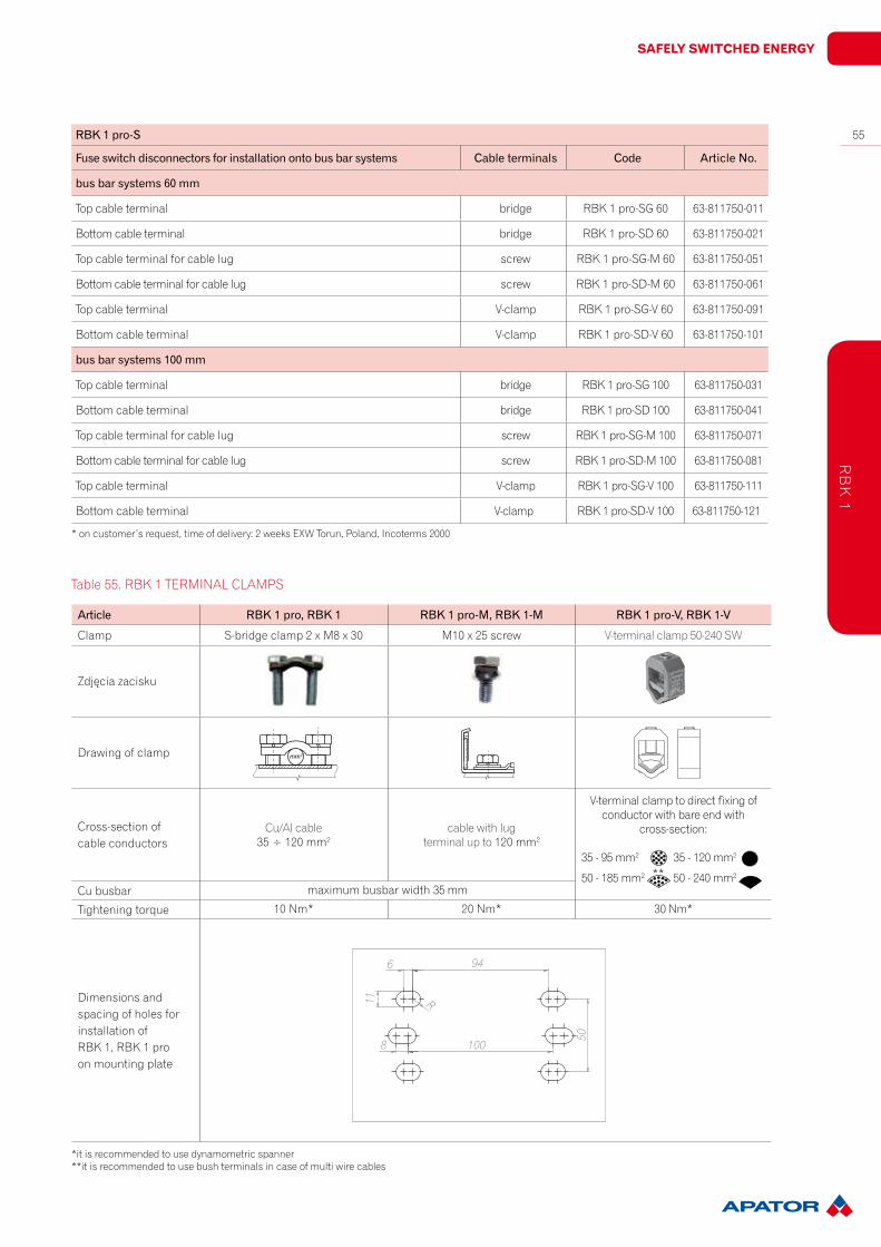
Article RBK1pro,RBK1 RBK1pro-M,RBK1-M RBK1pro-V,RBK1-V
clamp S-bridge clamp 2 x M8 x 30 M10 x 25 screw V-terminal clamp 50-240 Sw
Zdjęcia zacisku
Drawing of clamp
cross-section ofcable conductors
cu/al cable35 ÷ 120 mm2
cable with lugterminal up to 120 mm2
V-terminal clamp to direct fixing ofconductor with bare end with
cross-section:
35 - 95 mm2 35 - 120 mm2
50 - 185 mm2 50 - 240 mm2
cu busbar maximum busbar width 35 mm
tightening torque 10 Nm* 20 Nm* 30 Nm*
Dimensions and spacing of holes for installation ofrBK 1, rBK 1 pro on mounting plate
*it is recommended to use dynamometric spanner**it is recommended to use bush terminals in case of multi wire cables
table 55. rBK 1 terMiNaL cLaMPS
100
94
50
11
8
6
R
**
RBK1pro-S
Fuseswitchdisconnectorsforinstallationontobusbarsystems Cableterminals Code ArticleNo.
busbarsystems60mm
top cable terminal bridge rBK 1 pro-Sg 60 63-811750-011
Bottom cable terminal bridge rBK 1 pro-SD 60 63-811750-021
top cable terminal for cable lug screw rBK 1 pro-Sg-M 60 63-811750-051
Bottom cable terminal for cable lug screw rBK 1 pro-SD-M 60 63-811750-061
top cable terminal V-clamp rBK 1 pro-Sg-V 60 63-811750-091
Bottom cable terminal V-clamp rBK 1 pro-SD-V 60 63-811750-101
busbarsystems100mm
top cable terminal bridge rBK 1 pro-Sg 100 63-811750-031
Bottom cable terminal bridge rBK 1 pro-SD 100 63-811750-041
top cable terminal for cable lug screw rBK 1 pro-Sg-M 100 63-811750-071
Bottom cable terminal for cable lug screw rBK 1 pro-SD-M 100 63-811750-081
top cable terminal V-clamp rBK 1 pro-Sg-V 100 63-811750-111
Bottom cable terminal V-clamp rBK 1 pro-SD-V 100 63-811750-121
* on customer’s request, time of delivery: 2 weeks eXw torun, Poland, incoterms 2000

56
Switchgear
rBK 1-Sg*(top cable terminal)rBK 1-SD*(bottom cable terminal)
for installation on to 60 mm busbar systemtop/bottom cable terminals:
- M10 screw terminals - S-bridge clamps - V-shaped terminals
rBK 1, rBK 1 profor installation on mounting plate
cable terminals: - M10 screw terminals - S-bridge clamps - V-shaped terminals
rBK 1 pro - Ofor installation on mounting plate
with additional cable terminal shroudscable terminals:
- M10 screw terminals - S-bridge clamps - V-shaped terminals
rBK 1 VD-Mfor installation on mounting plate
photo of rBK 1 VD-M without coverand cable terminal shrouds
top cable terminal: - M10 screw terminals
bottom cable terminal: - V-shaped terminals
rBK 1 Vg-Mtop cable terminal:
- V-shaped terminals bottom cable terminal: - M10 screw terminals
rB
K 1
Safely Switched energy
57
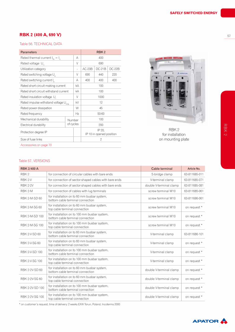
table 56. techNicaL Data
rBK 2for installation
on mounting plate
rBk 2 (400 a, 690 V)
Parameters RBK2
rated thermal current ith = in a 400
rated voltage un V 690
utilization category - ac-23B Dc-21B Dc-22B
rated switching voltage ue V 690 440 220
rated switching current ie a 400 400 400
rated short circuit making current ka 100
rated short circuit withstand current ka 100
rated insulation voltage ui V 1000
rated impulse withstand voltage uimp kV 12
rated power dissipation w 45
rated frequency hz 50-60
Mechanical durability Number of cycles
100
electrical durability 200
Protection degree iP iP 20, iP 10 in opened position
Size of fuse links 2
accessories on page 70
table 57. VerSiONS
RBK2/400A Cableterminal ArticleNo.
rBK 2 for connection of circular cables with bare ends S-bridge clamp 63-811685-011
rBK 2-V for connection of sector-shaped cables with bare ends V-terminal clamp 63-811685-071
rBK 2-2V for connection of sector-shaped cables with bare ends double V-terminal clamp 63-811685-081
rBK 2-M for connection of cables with lug terminals screw terminal M10 63-811685-061
rBK 2-M-SD 60 for installation on to 60 mm busbar system, bottom cable terminal connection screw terminal M10 63-811686-061
rBK 2-M-Sg 60 for installation on to 60 mm busbar system, top cable terminal connection screw terminal M10 on request *
rBK 2-M-SD 100 for installation on to 100 mm busbar system, bottom cable terminal connection screw terminal M10 on request *
rBK 2-M-Sg 100 for installation on to 100 mm busbar system, top cable terminal connection screw terminal M10 on request *
rBK 2-V-SD 60 for installation on to 60 mm busbar system, bottom cable terminal connection V-terminal clamp 63-811686-101
rBK 2-V-Sg 60 for installation on to 60 mm busbar system, top cable terminal connection V-terminal clamp on request *
rBK 2-V-SD 100 for installation on to 100 mm busbar system, bottom cable terminal connection V-terminal clamp on request *
rBK 2-V-Sg 100 for installation on to 100 mm busbar system, top cable terminal connection V-terminal clamp on request *
rBK 2-2V-SD 60 for installation on to 60 mm busbar system, bottom cable terminal connection double V-terminal clamp on request *
rBK 2-2V-Sg 60 for installation on to 60 mm busbar system, top cable terminal connection double V-terminal clamp on request *
rBK 2-2V-SD 100 for installation on to 100 mm busbar system, bottom cable terminal connection double V-terminal clamp on request *
rBK 2-2V-Sg 100 for installation on to 100 mm busbar system, top cable terminal connection double V-terminal clamp on request *
* on customer’s request, time of delivery: 2 weeks eXw torun, Poland, incoterms 2000
rB
K 2
58
Switchgearr
BK
2
130
ø13
50
9,5
14
R
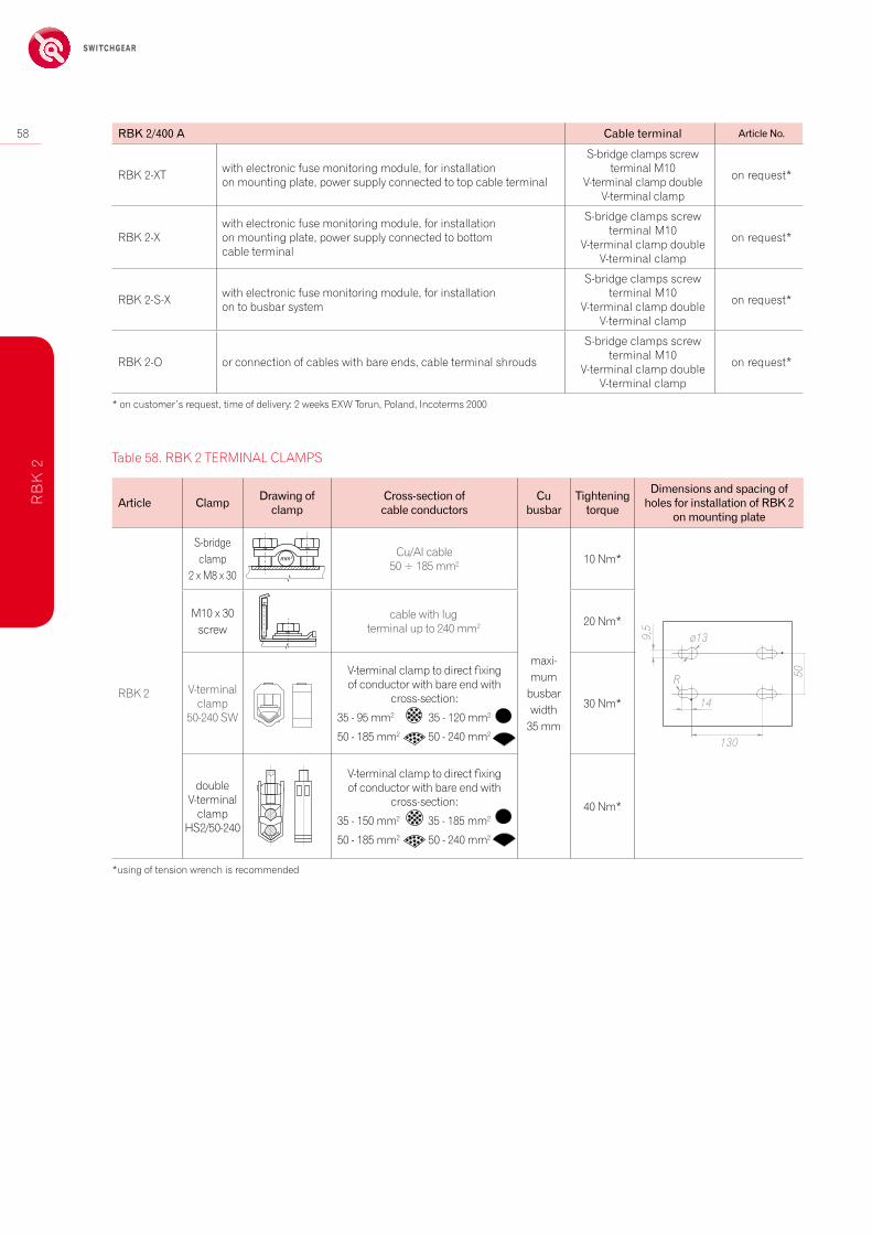
Article Clamp Drawingofclamp
Cross-sectionofcableconductors
Cubusbar
Tighteningtorque
DimensionsandspacingofholesforinstallationofRBK2
onmountingplate
rBK 2
S-bridge clamp
2 x M8 x 30
cu/al cable50 ÷ 185 mm2
maxi-mum
busbarwidth
35 mm
10 Nm*
M10 x 30 screw
cable with lugterminal up to 240 mm2 20 Nm*
V-terminal clamp
50-240 Sw
V-terminal clamp to direct fixing of conductor with bare end with
cross-section:
35 - 95 mm2 35 - 120 mm2
50 - 185 mm2 50 - 240 mm2
30 Nm*
double V-terminal
clamphS2/50-240
V-terminal clamp to direct fixing of conductor with bare end with
cross-section:
35 - 150 mm2 35 - 185 mm2
50 - 185 mm2 50 - 240 mm2
40 Nm*
*using of tension wrench is recommended
table 58. rBK 2 terMiNaL cLaMPS
* on customer’s request, time of delivery: 2 weeks eXw torun, Poland, incoterms 2000
RBK2/400A Cableterminal ArticleNo.
rBK 2-Xt with electronic fuse monitoring module, for installation on mounting plate, power supply connected to top cable terminal
S-bridge clamps screw terminal M10
V-terminal clamp double V-terminal clamp
on request*
rBK 2-Xwith electronic fuse monitoring module, for installation on mounting plate, power supply connected to bottom cable terminal
S-bridge clamps screw terminal M10
V-terminal clamp double V-terminal clamp
on request*
rBK 2-S-X with electronic fuse monitoring module, for installation on to busbar system
S-bridge clamps screw terminal M10
V-terminal clamp double V-terminal clamp
on request*
rBK 2-O or connection of cables with bare ends, cable terminal shrouds
S-bridge clamps screw terminal M10
V-terminal clamp double V-terminal clamp
on request*
Safely Switched energy
59
rB
K 2
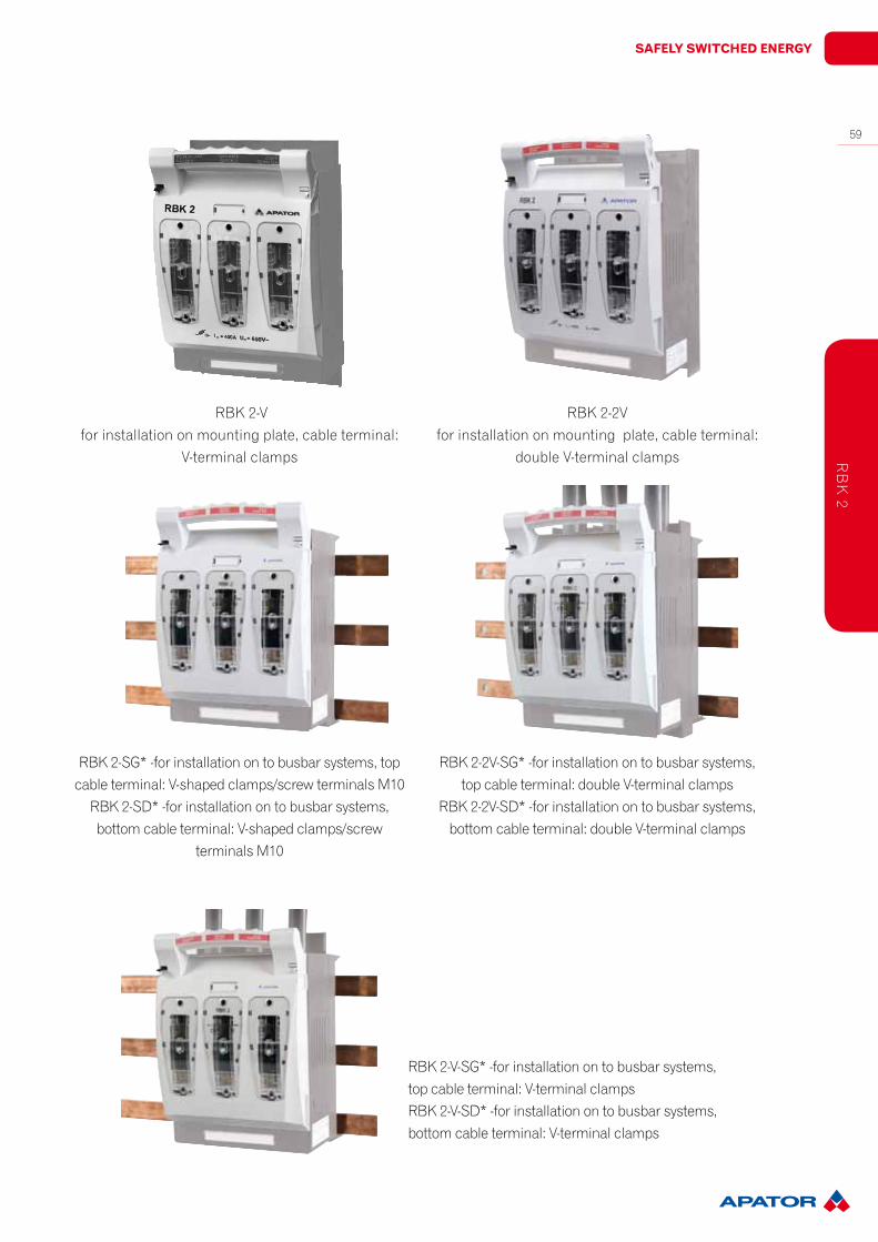
rBK 2-Vfor installation on mounting plate, cable terminal:
V-terminal clamps
rBK 2-2V for installation on mounting plate, cable terminal:
double V-terminal clamps
rBK 2-Sg* -for installation on to busbar systems, top cable terminal: V-shaped clamps/screw terminals M10
rBK 2-SD* -for installation on to busbar systems,bottom cable terminal: V-shaped clamps/screw
terminals M10
rBK 2-V-Sg* -for installation on to busbar systems,top cable terminal: V-terminal clampsrBK 2-V-SD* -for installation on to busbar systems,bottom cable terminal: V-terminal clamps
rBK 2-2V-Sg* -for installation on to busbar systems,top cable terminal: double V-terminal clamps
rBK 2-2V-SD* -for installation on to busbar systems,bottom cable terminal: double V-terminal clamps
60
Switchgearr
BK
3
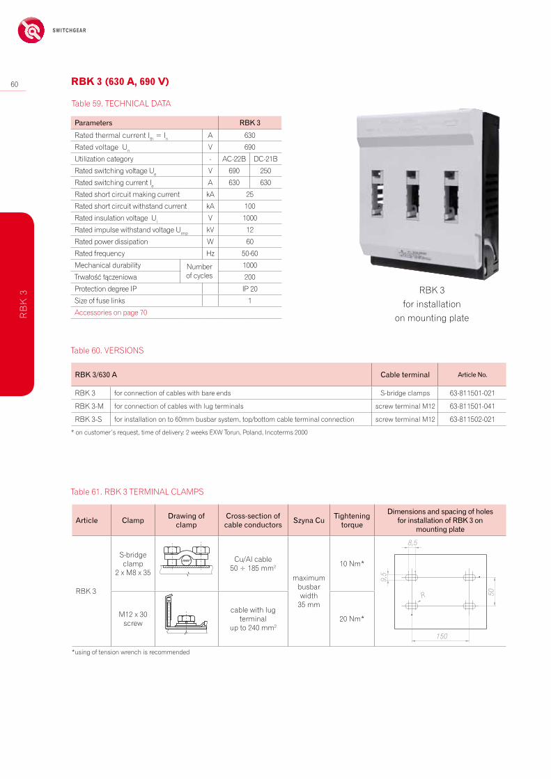
table 59. techNicaL Data
RBK3/630A Cableterminal ArticleNo.
rBK 3 for connection of cables with bare ends S-bridge clamps 63-811501-021
rBK 3-M for connection of cables with lug terminals screw terminal M12 63-811501-041
rBK 3-S for installation on to 60mm busbar system, top/bottom cable terminal connection screw terminal M12 63-811502-021
Article Clamp Drawingofclamp
Cross-sectionofcableconductors SzynaCu Tighteningtorque
DimensionsandspacingofholesforinstallationofRBK3on
mountingplate
rBK 3
S-bridge clamp
2 x M8 x 35
cu/al cable50 ÷ 185 mm2
maximum busbarwidth
35 mm
10 Nm*
M12 x 30 screw
cable with lugterminal
up to 240 mm220 Nm*
50
150
9,5
8,5
R
*using of tension wrench is recommended
table 60. VerSiONS
rBK 3for installation
on mounting plate
table 61. rBK 3 terMiNaL cLaMPS
rBk 3 (630 a, 690 V)
Parameters RBK3
rated thermal current ith = in a 630
rated voltage un V 690
utilization category - ac-22B Dc-21B
rated switching voltage ue V 690 250
rated switching current ie a 630 630
rated short circuit making current ka 25
rated short circuit withstand current ka 100
rated insulation voltage ui V 1000
rated impulse withstand voltage uimp kV 12
rated power dissipation w 60
rated frequency hz 50-60
Mechanical durability Number of cycles
1000
trwałość łączeniowa 200
Protection degree iP iP 20
Size of fuse links 1
accessories on page 70
* on customer’s request, time of delivery: 2 weeks eXw torun, Poland, incoterms 2000
Safely Switched energy
61
rB
K D
iMeN
SiON
S
207
91,5
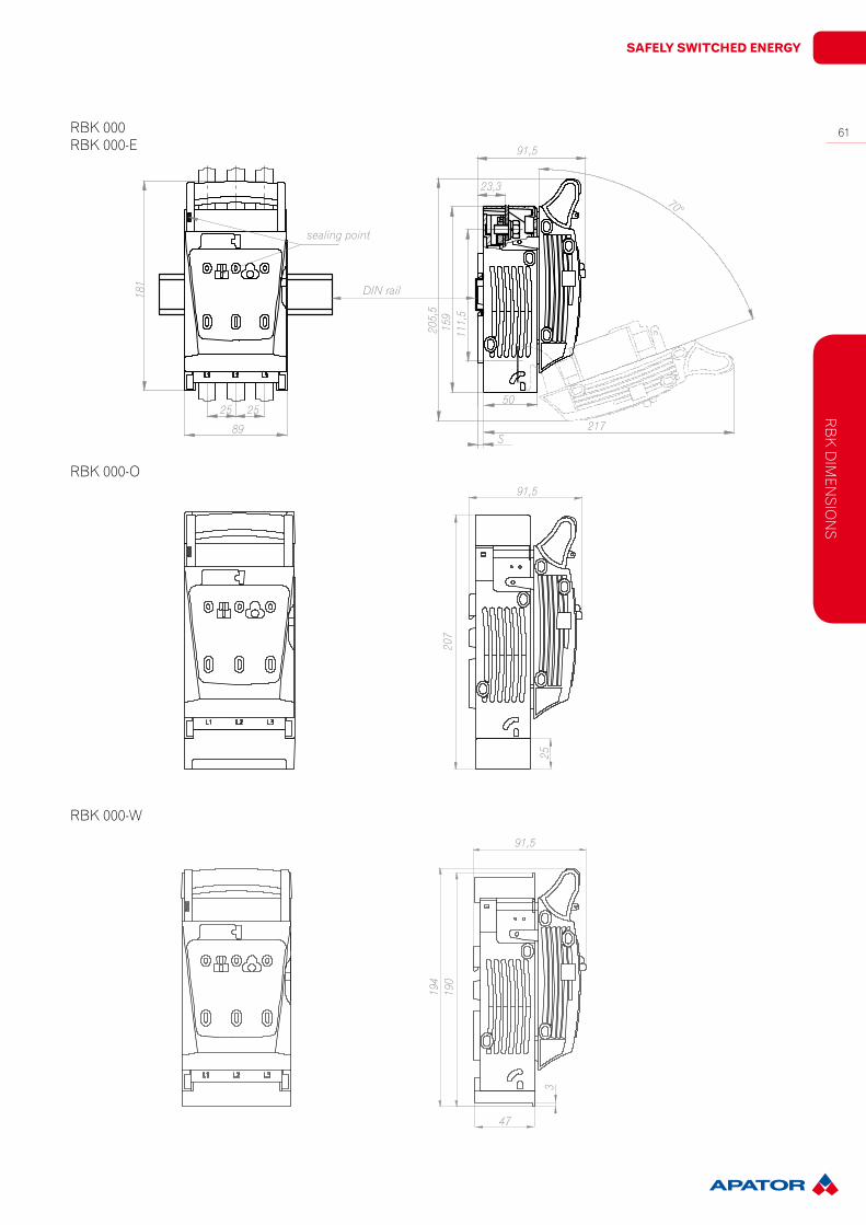
rBK 000-O
sealing point
DIN rail
25
89
181
205,
515
911
1,5
91,5
23,3
50
70°
rBK 000rBK 000-e
21725
194
190
91,5
rBK 000-w
S
253
47

62
Switchgearr
BK
DiM
eNSi
ON
S
207
18,3
8115
710
6,5*
42
212
10633 33
182 7,5
2
45
sealing point2
*122.5 mm for M screw terminal (for busbar and lug terminal)
rBK 00 / rBK 00 pro
198
184 20
7
18,3
81
106,
5*
rBK 00-w / rBK 00 pro-w,
*122.5 mm for M screw terminal (for busbar and lug terminal)
10633 33
7,5
sealing point
42
21245
rBK 000-Sg - top cable terminalrBK 000-SD - bottom cable terminal
busbar thickness 3-10 mm
70°
11270
24221
5
6058
60191
min
. 12
mm
max
. 30
mm
89
2525
Safely Switched energy
63
rB
K D
iMeN
SiON
S
207
47109
min
. 12
mm
mak
s. 3
0 m
m
60
busbar thickness 3-10 mm
70°
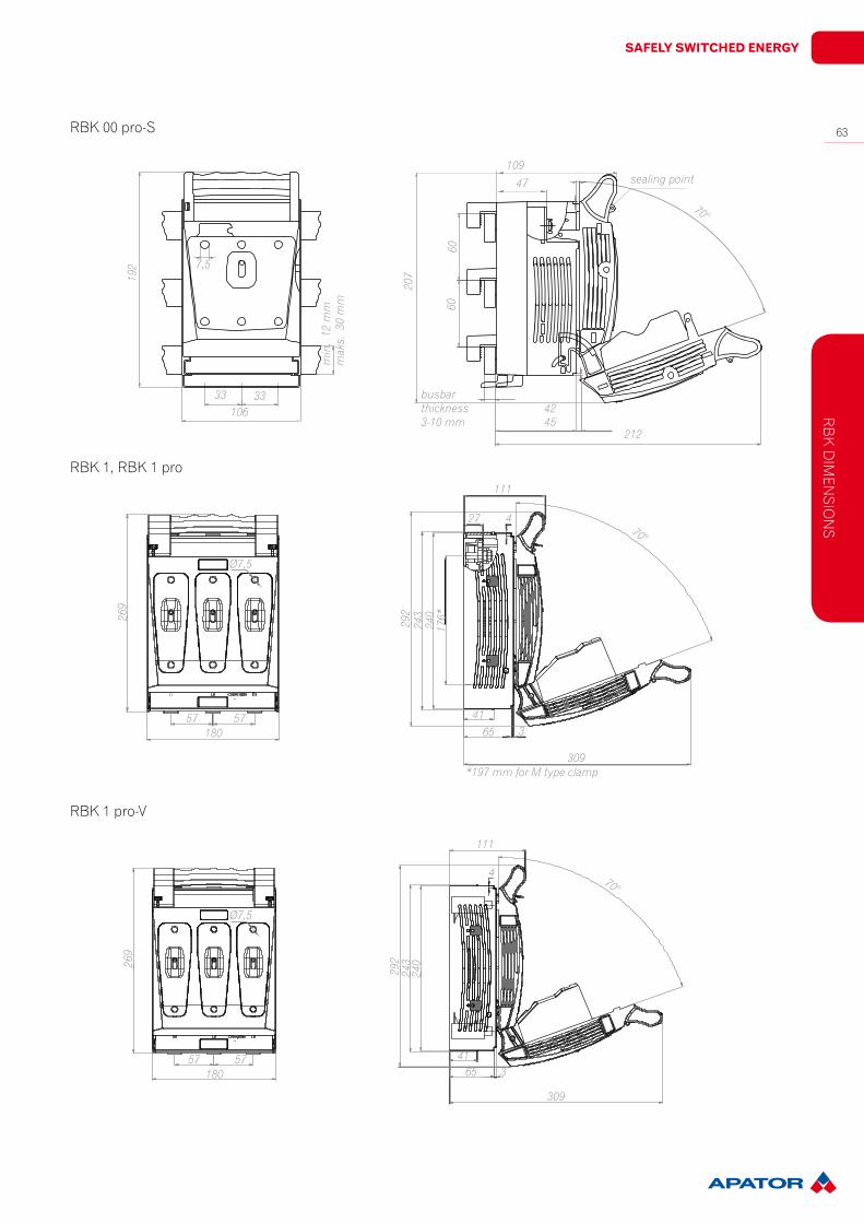
rBK 00 pro-S19
2 7,5
10633 33
42
21245
sealing point
60
rBK 1, rBK 1 pro
269
Ø7,5
57 57180
rBK 1 pro-V
292
243
240
176*
4165 3
309
111
27 470°
269
Ø7,5
57 57180
292
243
240
4165 3
309
111
470°
*197 mm for M type clamp

64
Switchgearr
BK
DiM
eNSi
ON
S
rBK 1 pro-SD, rBK 1 pro-SgA
Ø7,5
57 57180
A
C 292
243
165
470°
70339
14094
BrBK 1 pro-O
57 57180
4165 3
309
314
310
111
70°
Ø7,5
Thickness of the bus bar from 3 to 10 mm
A B C
60 mm 66 mm max 30 mm
100 mm 27-66 mm max 60 mmM,S,V types of clamps

Safely Switched energy
65
rB
K D
iMeN
SiON
S
130
319
70°
80
266
260
216
341
31
298
Ø7,5
208
65 65
sealing point
130
321
Ø7,5
208
325
rBK 2-V
Ø7,5
315
208
170
120
319
300
381
70°
rBK 2-2V
rBK 2
sealing point
sealing point
66
Switchgearr
BK
DiM
eNSi
ON
S
Ø7,5
208
298
65
154
70°
busbar thickness 5-10 mm
319
266
260
366109
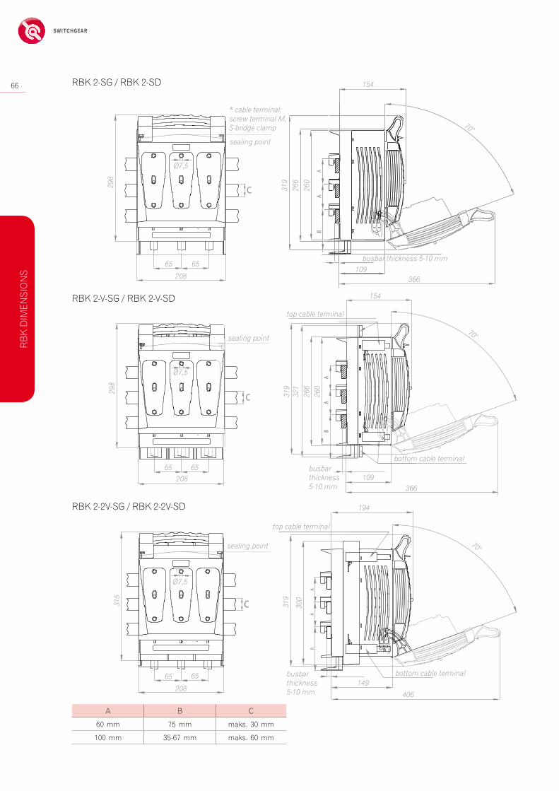
rBK 2-Sg / rBK 2-SD
70°
366
319
154
busbar thickness 5-10 mm
266
260
321
109
top cable terminal
bottom cable terminal
298
Ø7,5
20865 65
sealing point
rBK 2-V-Sg / rBK 2-V-SD
sealing point
65
top cable terminal
bottom cable terminalbusbar thickness 5-10 mm
319
300
406
194
149
Ø7,5
208
315
65 65
rBK 2-2V-Sg / rBK 2-2V-SD
sealing point 70°
A B C
60 mm 75 mm maks. 30 mm
100 mm 35-67 mm maks. 60 mm
* cable terminal: screw terminal M, S-bridge clamp

Safely Switched energy
67
80 80
154
308
80 80
250
155102
17
6060
94
M6x10
60 mm busbar system adapter - fixed to the fuse switch disconnector main base with M6x10 screws
fixing point
rBK 3-S
140
70°
337
212
31-33
48
86,5
371250
80 80
308
154
rBK 3
rB
K D
iMeN
SiON
S
68
Switchgeara
DD
itiO
Na
L a
cc
eSSO
rie
S
190
135117109
240
258
Ø12
Ø7
full coversealing point
82
35-240SE30Nm
35-240SE30Nm
35-240SE30Nm
100
214
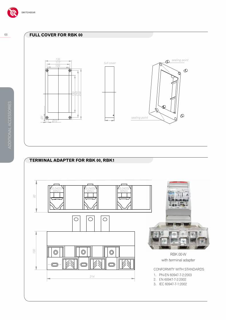
cONFOrMitY with StaNDarDS
1. PN-eN 60947-7-2:2003 2. eN 60947-7-2:20023. iec 60947-7-1:2002
fUll cOVer fOr rBk 00
terMinal adaPter fOr rBk 00, rBk1
sealing point
rBK 00-wwith terminal adapter

Safely Switched energy
69cOVering Of rBk fUSe Switch diScOnnectOrS (rear inStallatiOn)
Typ A B C D
rBK 000 104 166 94 156
rBK 000-S, rBK 000-w 104 205 94 195
rBK 00, rBK 00 pro, rBK 00 pro-S 120 207 110 197
rBK 00-w 120 207 110 182
rBK 1, rBK 1-S 198 262 186 250
rBK 2, rBK 2-S 230 285 209 255
rBK 2-V, rBK 2-2V 230 340 209 255
rBK 3, rBK 3-S 272 328 258 316
hole in front cover for RBK fuse switch disconnector
C
B D
A
front cover
RBK 000RBK 00RBK 00 proRBK 1RBK 2 RBK 3
RBK 3-S
RBK 000-SGRBK 00 proSGRBK 1 pro-SGRBK 2-SG
RBK 000-SDRBK 00 pro-SDRBK 1 pro-SD RBK 2-SDRBK 3-S
table 62. FrONt cOVer DiMeNSiONS
electrical diagraMS (rBk 1-S, rBk 3-S - POSSiBle BOttOM caBle terMinal cOnnectiOn)
aD
DitiO
Na
L ac
ceSSO
rieS
70
Switchgeara
cc
eSSO
rie
S r
BK
Articlenumber Opis Zdjęcie
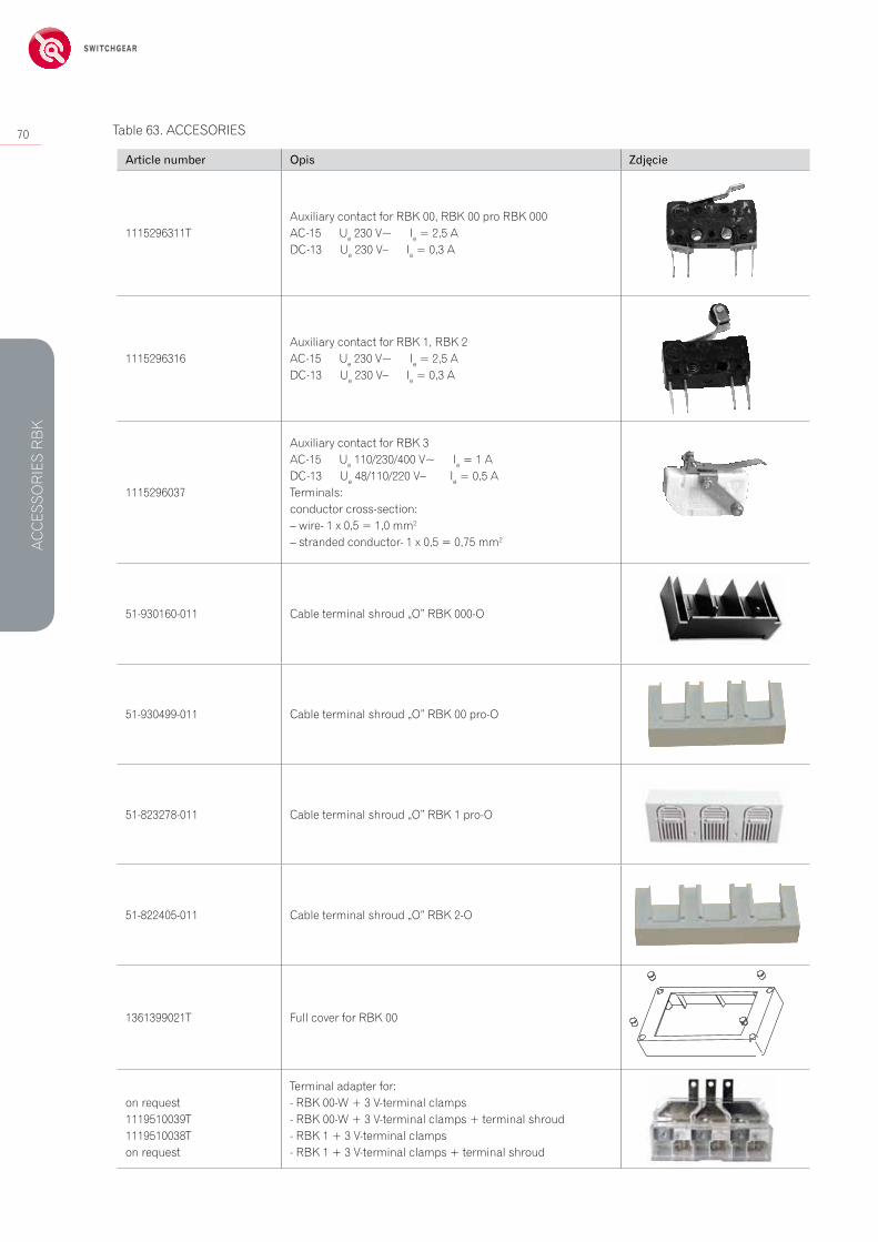
1115296311tauxiliary contact for rBK 00, rBK 00 pro rBK 000ac-15 ue 230 V~ ie = 2,5 aDc-13 ue 230 V– ie = 0,3 a
1115296316auxiliary contact for rBK 1, rBK 2ac-15 ue 230 V~ ie = 2,5 aDc-13 ue 230 V– ie = 0,3 a
1115296037
auxiliary contact for rBK 3ac-15 ue 110/230/400 V~ ie = 1 a Dc-13 ue 48/110/220 V– ie = 0,5 aterminals:conductor cross-section:– wire- 1 x 0,5 = 1,0 mm2
– stranded conductor- 1 x 0,5 = 0,75 mm2
51-930160-011 cable terminal shroud „O” rBK 000-O
51-930499-011 cable terminal shroud „O” rBK 00 pro-O
51-823278-011 cable terminal shroud „O” rBK 1 pro-O
51-822405-011 cable terminal shroud „O” rBK 2-O
1361399021t Full cover for rBK 00
on request1119510039t1119510038ton request
terminal adapter for:- rBK 00-w + 3 V-terminal clamps- rBK 00-w + 3 V-terminal clamps + terminal shroud- rBK 1 + 3 V-terminal clamps- rBK 1 + 3 V-terminal clamps + terminal shroud
table 63. acceSOrieS
Safely Switched energy
71
1. Wkładki zwierające2. Drążek izolacyjny3. Zacisk uziemiający4. Linka zwierająca5. Linka uziemiająca6. Punkt połączenia linek 7. Plastikowa walizka
5
1
3
2
4
6
7
350 mm
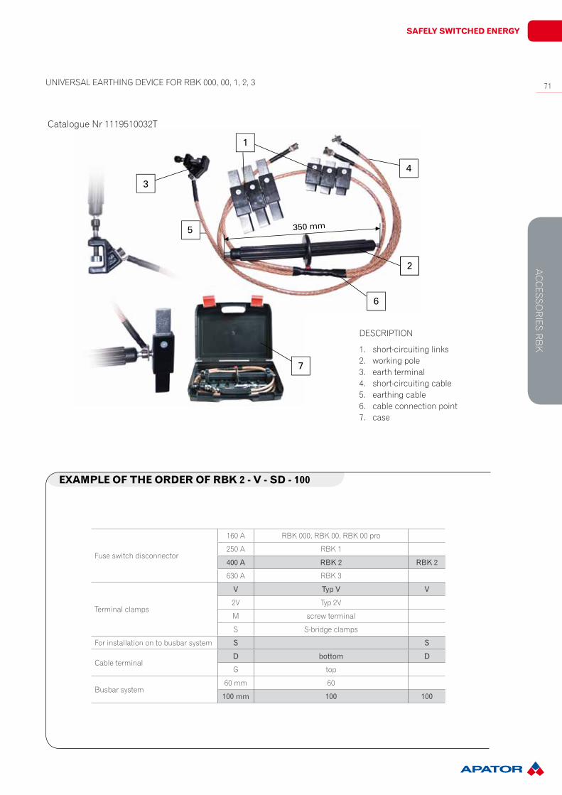
1. short-circuiting links2. working pole3. earth terminal4. short-circuiting cable5. earthing cable6. cable connection point7. case
DeScriPtiON
uNiVerSaL earthiNg DeVice FOr rBK 000, 00, 1, 2, 3
catalogue Nr 1119510032t
exaMPle Of the Order Of rBk 2 - V - Sd - 100
Fuse switch disconnector
160 a rBK 000, rBK 00, rBK 00 pro
250 a rBK 1
400A RBK2 RBK2
630 a rBK 3
terminal clamps
V TypV V
2V typ 2V
M screw terminal
S S-bridge clamps
For installation on to busbar system S S
cable terminalD bottom D
g top
Busbar system60 mm 60
100mm 100 100
ac
ceSSO
rieS r
BK