a quick tutorial for drawing photolithography masks in...
TRANSCRIPT

A Quick Tutorial for Drawing
Photolithography Masks in AutoCAD
Marc Ghossoub
Jeffrey Grau
Revision 1
May 09, 2014
University of Illinois at Urbana-Champaign
Frederick Seitz Materials Research Laboratory

University of Illinois Rev -1- May 09, 2014
1
0 – This tutorial assumes some basic knowledge of AutoCAD. It is by no means
comprehensive but serves as a guide for simple mask design.
1 – Open AutoCAD 2015

University of Illinois Rev -1- May 09, 2014
2
2 – Create a new Drawing. Use the “acad.dwt” template.

University of Illinois Rev -1- May 09, 2014
3
3 – Define a new layer. Here, we named it Layer1.

University of Illinois Rev -1- May 09, 2014
4
Change its color to distinguish it from other layers. Here we chose green.
Choose the new layer to work with.

University of Illinois Rev -1- May 09, 2014
5
4 – Define the edges of your mask (4 by 4 inches, etc). This will help locate your
features relative to the center of the mask and the edges. Use units of micrometers.
This means that a dimension of 100 nm is defined as 0.1. A 4 by 4 inch square is thus
defined as a 101600 by 101600 square. Here, we drew a 101600 by 101600 square to
define the mask edges.
Click on Zoom Extents button to show all mask edges.

University of Illinois Rev -1- May 09, 2014
6
5 – Draw the boundaries of your mask features using rectangles, circles and lines. We
will eventually hatch the inside of these boundaries to create the mask features. The
hatched area is the area that appears transparent in your final mask.
For example, for a square opening, first draw a square.
Then hatch the interior of the square.

University of Illinois Rev -1- May 09, 2014
7
When prompted for it, select automatically adjust the hatch scale.
Final hatched area.
The procedure is a bit trickier for curved and rounded features, especially large
rounded areas. It is important to define an “interior” hatch and a “boundary” hatch

University of Illinois Rev -1- May 09, 2014
8
for such areas to reduce the final number of flash counts needed to make the mask.
This reduces the time needed to create the mask and therefore its cost. Let’s illustrate
this with a simple circle as an example.
Draw a circle.
Define a polygon with multiple edges (even number: 4 – 8 – 16) inside the circle.

University of Illinois Rev -1- May 09, 2014
9
Insert inside the circle (inscribed).

University of Illinois Rev -1- May 09, 2014
10
Use the polygon’s vertices as a guide to fill the circle with rectangles, and then delete
the polygon. This procedure can be used for curved lines by defining a suitable
polygon first to get the vertices and then filling with squares and rectangles.
University of Illinois Rev -1- May 09, 2014
11
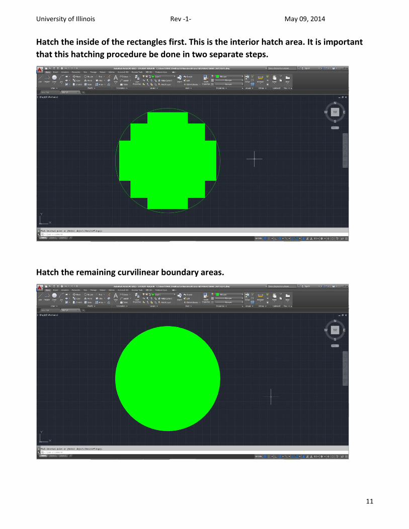
Hatch the inside of the rectangles first. This is the interior hatch area. It is important
that this hatching procedure be done in two separate steps.
Hatch the remaining curvilinear boundary areas.

University of Illinois Rev -1- May 09, 2014
12
6 – After the drawings are all done and the hatching complete, remove all the lines
around the hatch areas by selecting them and deleting them.
Remember to also delete the internal lines defining the rectangles.

University of Illinois Rev -1- May 09, 2014
13
At the end, the drawing should only have hatched areas with no boundary lines.

University of Illinois Rev -1- May 09, 2014
14
7 – This is your mask file, save it as an AutoCAD 2013 .dxf file.