a novel of bidirectional dc-dc converter drive - · pdf fileboost/buck converter. ... voltage...
TRANSCRIPT

International Journal of Modern Engineering Research (IJMER)
www.ijmer.com Vol.2, Issue.2, Mar-Apr 2012 pp-186-196 ISSN: 2249-6645
www.ijmer.com 186 | P a g e
N.MAHESH M-Tech Scholar, Power Electronics and Drives,
Department Of Electrical And Electrical Engineering,
Koneru Lakshmaiah University, Guntur,(A.P), India.
D.SESHI REDDY Associate professor,
Department Of Electrical And Electrical Engineering,
Koneru Lakshmaiah University, Guntur,(A.P),India.
Abstract: - A Novel of bidirectional DC-DC converter
drive is presented in this paper. The circuit
configuration of the proposed converter is very simple.
The proposed converter employs a coupled inductor
with same winding turns in the primary and secondary
sides. In step-up mode, the primary and secondary
windings of the coupled inductor are operated in
parallel charge and series discharge to achieve high
step-up voltage gain. In step-down mode, the primary
and secondary windings of the coupled inductor are
operated in series charge and parallel discharge to
achieve high step-down voltage gain. Thus, the proposed
converter has higher step-up and step-down voltage
gains than the conventional bidirectional DC-DC
boost/buck converter. Under same electric specifications
for the proposed converter and the conventional
bidirectional boost / buck converter, the average value
of the switch current in the proposed converter is less
than the conventional bidirectional boost / buck
converter. The operating principle and steady-state
analysis are discussed in detail. Finally, a 70 / 210 V
simulation circuit is simulated in MATLAB/Simulink to
verify the performance for the automobile dual - battery
drive system.
Index Terms: - Bidirectional DC-DC converter drive,
coupled inductor.
I .Introduction Bidirectional DC–DC converters are used to transfer
the power between two DC sources in either direction.
These converters are widely used in applications, such as
hybrid electric vehicle energy systems [1]–[4],
uninterrupted power supplies [5], [6], fuel-cell Hybrid
power systems [7]–[10], PV hybrid power systems [11],
[12] and battery chargers [13]–[15]. Many bidirectional
DC-DC converters have been researched. The bidirectional
DC-DC fly back converters are more attractive due to
simple structure and easy control. However, these
converters suffer from high voltage stresses on the power
devices due to the leakage-inductor energy of the
transformer. In order to recycle the leakage inductor energy
and to minimize the voltage stress on the power devices,
some literatures present the energy regeneration techniques
to clamp the voltage stress on the power devices and to
recycle the leakage-inductor energy, some literatures
research the isolated bidirectional DC-DC converters,
which include the half-bridge types and full-bridge types.
These converters can provide high step-up and step-down
voltage gainby adjusting the turn’s ratio of the transformer.
For non-isolated applications, the non-isolated bidirectional
DC-DC converters, which include the conventional
boost/buck types, multi-level type, three-level type,
sepic/zeta type, switched-capacitor type, and coupled-
inductor type, are presented. The multi-level type is a
magnetic-less converter, but 12 switches are used in this
converter. If higher step-up and step-down voltage gains are
required, more switches are needed. This control circuit
becomes more complicated. In the three-level type, the
voltage stress across the switches on the three-level type is
only half of the conventional type. However, the step-up
and step-down voltage gains are low. Since the sepic/zeta
type is combined of two power stages, the conversion
efficiency will be decreased.
The development of bidirectional dc-dc converters has
recently become increasingly important for clean-energy
vehicle applications because battery-based energy storage
systems are required for cold starting and battery recharging
[16], [17], [18]. Bidirectional converters transfer power
between two dc sources in both directions. However, back-
up power from the battery is supplied using a bidirectional
converter, which is employed in many uninterrupted power
supplies (UPS), the front-end stage for clean-energy sources
and dc motor driver circuits. The dc back-up energy system
typically consists of numerous low-voltage-type batteries.
Although a storage battery series string can provide high
voltage, slight mismatches or temperature differences can
cause a charge imbalance when the series string is charged
as a unit Charge equalization cycles must be employed to
correct this imbalance. However, conventional approaches
to this process will stress the batteries, shorten their life and
are limited to low-capacity power. Batteries arranged in
parallel strings can enhance the power redundancy supplied
by a battery and alleviate the problems caused by storage
battery series strings. However, the output voltage remains
low in this parallel connection configuration. A highly
efficient bidirectional DC–DC converter with high-voltage
diversity is a key component for batteries connected in
parallel. Bidirectional DC - DC converters with
transformer-based structures are the most common
topologies. Soft switching techniques are generally applied
to reduce the corresponding switching losses. These
mechanisms with isolated transformers have high
conduction losses because four to nine power switches are
required. Many applications call for high-step-up converters
that do not require isolation, such as the front-end converter
A Novel of Bidirectional DC-DC converter drive

International Journal of Modern Engineering Research (IJMER)
www.ijmer.com Vol.2, Issue.2, Mar-Apr 2012 pp-186-196 ISSN: 2249-6645
www.ijmer.com 187 | P a g e
with dual inputs. Accordingly, practical implementation is
complex and costly. Switched-capacitor dc–dc converters
have attracted much attention as an alternative method for
providing bidirectional power flow control. However,
increased switching loss and current stress are the critical
drawbacks. The primary challenge is to design a circuit that
has few switching devices and capacitors. Generally, the
bidirectional converter in the UPS must generally boost 48–
400 V, which is appropriate for eightfold step-up voltage
gain. Zhao and Lee developed a family of highly efficient,
high-step-up dc–dc converters by adding only one
additional diode and a small capacitor [19]. This capacitor
can recycle leaked energy and eliminate the reverse-
recovery problem. In this approach the magnetic core can
be regarded as a fly-back transformer and most energy is
stored in the magnetic inductor.
1.1 COUPLED INDUCTOR: The pair of coupled coils shown in figure has currents,
voltages and polarity dots indicated. In order to show
𝑀12 = 𝑀21 we begin by letting all currents and voltages are
zero, thus establishing zero initial energy storage in the
network. We then open –circuit the right–hand terminal pair
and increase I1 from zero to some constant value 𝐼1 at time t
= t1.The power entering the network from left at any instant
is
Fig 1 Coupled inductors
𝑉1𝑖1 = 𝐿1𝑑𝑖1
𝑑𝑡𝑖1 (1)
and the power entering from the right is
𝑉2𝐼2 = 0 (2)
Since i2=0
The energy stored within the network when i1 = I1 is thus
𝑣1𝑖1 𝑑𝑡 = 𝑙1𝑖1 𝑑𝑖1 =1
2
𝐼1
0
𝑡1
0 𝐿1𝐼12 (3)
We now hold 𝐼1 constant, 𝑖1 = 𝐼1, and let 𝐼2 change from
zero at t=t1 to some constant value 𝐼2 at t=t2.The energy
delivered from the right-hand source is thus
𝑣2𝑖2 𝑑𝑡 = 𝑙2𝑖2 𝑑𝑖2 =1
2
𝐼2
0
𝑡2
𝑡1 𝐿2𝑖22 (4)
However, even though the value of 𝐼1 remains constant, the
left-hand source also delivers energy to the network during
this time interval
𝑣1𝑖1 𝑑𝑡 = 𝑀12𝑑𝑖2
𝑑𝑡
𝑡2
𝑡1
𝑡2
𝑡1𝑖1𝑑𝑡 = 𝑀12𝐼1 𝑑𝑖2 =
𝐼2
0
𝑀12𝐼1𝐼2 (5)
The total energy stored in the network when both i1 and i2
have reached constant values is
𝑊𝑡𝑜𝑡𝑎𝑙 =1
2𝐿1𝐼1
2 +1
2𝐿2𝐼2
2 + 𝑀12 𝐼1𝐼2 (6)
Now, we may establish the same final currents in this
network by allowing the currents to reach final values to the
reverse order
𝑊𝑡𝑜𝑡𝑎𝑙 =1
2𝐿1𝐼1
2 +1
2𝐿2𝐼2
2 + 𝑀21 𝐼1𝐼2 (7)
The only difference is the interchange of the mutual
inductance 𝑀21 and 𝑀12
𝑀12 = 𝑀21 = 𝑀 and
𝑊 =1
2𝐿1𝐼1
2 +1
2𝐿1𝐼2
2 + 𝑀𝐼1𝐼2 (8)
If one current enters a dot-marked terminal while the other
leaves a dot marked terminal
𝑊 =1
2𝐿1𝐼1
2 +1
2𝐿1𝐼2
2 − 𝑀𝐼1𝐼2 (9)
From equations 8 and 9 were derived final values of the two
currents as constant, these ―constants‖ can have any value
and the energy expressions correctly represent the energy
stored when the instantaneous values 𝑖1 and 𝑖2 are 𝐼1 and 𝐼1
respectively
𝑊 𝑡 1
2 𝐿1 𝑖1 𝑡
2 +1
2 𝐿2 𝑖2 𝑡
2 ± 𝑀 𝑖1 𝑡 𝑖2 𝑡
(10)
1.1.1 The coupling coefficient
The degree to which M approaches its maximum value is
described by the coupling coefficient, defined as
𝐾 =𝑀
𝐿1𝐿2 (11)
Since M≤ 𝐿1𝐿2
0 ≤ k ≤ 1
The larger values of the coefficient of coupling are obtained
with coils which are physically closer, which are wound or
oriented to provide a larger common magnetic flux, or
provided with a common path through a material which
serves to concentrate and localize the magnetic flux. Coils
having a coefficient of coupling close to unity are said to be
tightly coupled.

International Journal of Modern Engineering Research (IJMER)
www.ijmer.com Vol.2, Issue.2, Mar-Apr 2012 pp-186-196 ISSN: 2249-6645
www.ijmer.com 188 | P a g e
1.2 DC MACHINE: Back EMF induced in motor
armature. When current passed through the armature of dc
machines and its field coils excited torque is established
and motor rotates the direction of rotation can be reversed
by reversing either armature current or polarity of the
magnets. Rotation of the armature gives rise to an induced
emf which according to Lenz’s law, will oppose the flow of
current. Hence if
Ea=the numerical value of the induced emf.
Va=the numerical value of the applied voltage.
The armature currents is given by
𝐼𝑎= (𝑉𝑎 –𝐸𝑎 ) /𝜏𝑚
𝑉𝑎= 𝐸𝑎 + 𝐼𝑎𝜏𝑚
The power input 𝑉𝑎 𝐼𝑎 =𝐸𝑎 𝐼𝑎+ 𝐼𝑎2𝑟𝑚 (12)
The emf generated by the armature must have a perfectly
definite value for particular value of the load current
𝐸𝑎 = 𝑉𝑎 - 𝐼𝑎 𝑟𝑚 (13)
The induced emf is also determined from ordinary
considerations of flux, number of conductors and speed,
and its thus
𝐸𝑎 =𝑍𝑒×2pᴓn (14)
From above 13 and 14 equations are equal we get
𝑉𝑎 - 𝐼𝑎 𝑟𝑚 = 𝑍𝑒×2pᴓn
n= 𝑉𝑎 − 𝐼𝑎 𝑟𝑚
𝑍𝑒×2pᴓn (15)
1.2.1 Field control:- In field control the applied armature
voltage v is maintained constant. Then the speed is
represented by equation as
𝝎𝒎 𝜶 𝟏
𝑰𝒇 (16)
1.2.2 Armature control:- In this the field current is
maintained constant. Then the speed is derived from the
equation as
𝜔𝑚 = (𝑣 − 𝑖𝑎𝑅𝑎 ) (17)
Hence, varying the applied voltage changes speed.
Reversing the applied voltage changes the direction of
rotation of the motor
1.2.3 Armature and Field control:- By combination
armature and field control for speeds below and above the
rated speed, respectively, a wide range of speed control is
possible
𝑇𝑒 = 𝐾∅𝑓 𝑖𝑎 (18)
Can be normalized if it is divided by rated torque
Which is expressed as
𝑇𝑒𝑟 = 𝐾∅𝑓𝑟 𝑖𝑎𝑟 (19)
𝑇𝑒𝑛 =𝑇𝑒
𝑇𝑒𝑟= 𝐾
∅𝑓 𝑖𝑎
𝐾∅𝑓𝑟 𝑖𝑎𝑟= ∅𝑓𝑛 𝑖𝑎𝑛 , 𝑝. 𝑢. (20)
Fig 2 Dc motor basic parts
Hence the speed of dc motor may be controlled by
1. Varying the value of the flux.
2. Varying the value of the voltage applied to
the motor armature
3. Varying the value of the effective number of
conductors in series.
Normalized eliminates machine constants, compacts
the performance equation, and enables the
visualization of performance characteristics
regardless of machine size on same scale. the
normalized torque, flux and armature current are
𝑇𝑒𝑛 =𝑇𝑒
𝑇𝑒𝑟, 𝑝. (21)
∅𝑓𝑛 =∅𝑓
∅𝑓𝑟 , p.u (22)
𝑖𝑎𝑛 =𝑖𝑎
𝑖𝑎𝑟, 𝑝. 𝑢 (23)
As the armature current is maintained at 1 p.u
𝑇𝑒𝑛 = ∅𝑓𝑛 , 𝑝. 𝑢 (24)

International Journal of Modern Engineering Research (IJMER)
www.ijmer.com Vol.2, Issue.2, Mar-Apr 2012 pp-186-196 ISSN: 2249-6645
www.ijmer.com 189 | P a g e
Hence normalized electromagnetic torque
characteristics coincides with normalized field flux,
similarly the air gap power is,
𝑝𝑎𝑛 = 𝑒𝑛 𝑖𝑎𝑛 , 𝑝. 𝑢 (25)
Where 𝑒𝑛 is the normalized induced emf.
As 𝑖𝑎𝑛 is set to 1 p.u., the normalized air gap power
becomes
𝑝𝑎𝑛 = 𝑒𝑛 , 𝑝. 𝑢 (26)
Fig 3 normalized characteristics of variable –speed
DC motor
II. STEP–UP MODE
The proposed converter in step-up mode is
shown in Fig 5. The pulse width modulation (PWM)
technique is used to control the switches S1 and S2
simultaneously. The switch S3 is the Synchronous
rectifier.
2.1 CCM Operation
Mode 1: During this time interval, S1 and S2 are
turned on and S3 is turned off. The current flow path
is shown in Fig 5(a). The energy of the low-voltage
side VL is transferred to the coupled inductor.
Meanwhile, the primary and secondary windings of
the coupled inductor are in parallel. The energy
stored in the capacitor CH is discharged to the load.
Thus, the voltages across L1 and L2 are obtained as
𝑢𝐿1 = 𝑢𝐿2 = 𝑉𝐿 (27)
By substituting above equations we get
𝑑𝑖𝐿1(𝑡)
𝑑𝑡=
𝑑𝑖𝐿2(𝑡)
𝑑𝑡=
𝑉𝐿
1+𝑘 𝐿, (28)
Mode-2: During this time interval S1 and S2 are
turned on and S3 is turned off. The current flow path
is shown in Fig. 5(b). The energy of the low-voltage
side VL is transferred to the coupled inductor.
Meanwhile, the primary and secondary windings of
the coupled inductor are in parallel. The energy
stored in the capacitor CH is discharged to the load.
Thus, the voltages across L1 and L2 are obtained as
𝑖𝐿1 = 𝑖𝐿2
𝑢𝐿1 + 𝑢𝐿2 = 𝑉𝐿 − 𝑉𝐻 (29)
By substituting above equations we get
𝑑𝑖𝐿1(𝑡)
𝑑𝑡=
𝑑𝑖𝐿2(𝑡)
𝑑𝑡=
𝑉𝐿−𝑉𝐻
2 1+𝑘 𝐿, (30)
By using the state-space averaging method, the
following equation is derived from
𝐷𝑉𝐿
1+𝑘 𝐿+
1−𝐷 (𝑉𝐿−𝑉𝐻 )
2 1+𝑘 𝐿= 0 (31)
By simplifying we get
𝐺𝐶𝐶𝑀(𝑠𝑡𝑒𝑝 −𝑢𝑝 ) =𝑉𝐻
𝑉𝐿=
1+𝐷
1−𝐷 (32)

International Journal of Modern Engineering Research (IJMER)
www.ijmer.com Vol.2, Issue.2, Mar-Apr 2012 pp-186-196 ISSN: 2249-6645
www.ijmer.com 190 | P a g e
Fig4 step up mode
Fig 5: Some typical waveforms of the proposed converter in step-up mode (a) CCM operation (b) DCM
operation (c) Mode 3 for DCM Mode

International Journal of Modern Engineering Research (IJMER)
www.ijmer.com Vol.2, Issue.2, Mar-Apr 2012 pp-186-196 ISSN: 2249-6645
www.ijmer.com 191 | P a g e
2.2 DCM Operation Mode 1: During this time interval, S1 and S2 are
turned on and S3 is turned off. The current flow path
is shown in Fig. 5(a) The operating principle is same
as that for the mode 1 of CCM operation
𝐼𝐿1𝑝 = 𝐼𝐿2𝑝 =𝑉𝐿𝐷𝑇𝑠
1+𝑘 𝐿 (33)
Mode 2: During this time interval, S1 and S2 are
turned off and S3 is turned on. The current flow path
is shown in Fig 5 (b). The low-voltage side VL and
the coupled inductor are in series to transfer their
energies to the capacitor CH and the load. Meanwhile,
the primary and secondary windings of the coupled
inductor are in series. The currents iL1 and iL2
through the primary and secondary windings of the
coupled inductor are decreased to zero at t = t2. From
eqn, another expression of IL1p and IL2p is given by
𝐼𝐿1𝑝 = 𝐼𝐿2𝑝 =(𝑉𝐻−𝑉𝐿)𝐷2𝑇𝑠
2 1+𝑘 𝐿 (34)
Mode 3: During this S1 and S2 are still turned off
and S3 is still turned on. The current flow path is
shown in Fig 5(c). The energy stored in the coupled
inductor is zero. Thus, iL1 and iL2 are equal to zero.
The energy stored in the capacitor CH is discharged
to the load. From above equation, is derived as
follows
𝐷2 =2𝐷𝑉𝐿
𝑉𝐻−𝑉𝐿 (35)
From Fig, the average value of the output capacitor
current during each switching period is given by
𝐼𝑐𝐻 =1
2𝐷2𝑇𝑠𝐼𝐿1𝑝−𝐼𝑜𝑇𝑠
𝑇𝑠=
1
2𝐷2𝐼𝐿1𝑝 − 𝐼𝑜 (36)
By substituting above values we get
𝐼𝑐𝐻 =𝐷2𝑉𝐿
2𝑇𝑠
1+𝑘 𝐿(𝑉𝐻−𝑉𝐿)−
𝑉𝐻
𝑅𝐻 (37)
Since IcH is equal to zero under steady state, above
equations can be rewritten as follows:
𝐷2𝑉𝐿
2𝑇𝑠
1+𝑘 𝐿(𝑉𝐻−𝑉𝐿)=
𝑉𝐻
𝑅𝐻 (38)
Then, the normalized inductor time constant is
defined as
𝑇𝐿𝐻 ≡𝐿
𝑅𝐻𝑇𝑠=
𝐿𝑓𝑠
𝑅𝐻 (39)
where fs is the switching frequency. Substituting
above equations we get, the voltage gain is given by
𝐺𝐷𝐶𝑀(𝑠𝑡𝑒𝑝 −𝑢𝑝 ) =𝑉𝐻
𝑉𝐿=
1
2+
1
4+
𝐷2
(1+𝑘)𝜏𝐿𝐻 (40)
2.3 Boundary Operating Condition of CCM and
DCM
When the proposed converter in step-up mode is
operated in boundary conduction mode (BCM), the
voltage gain of CCM operation is equal to the voltage
gain of DCM operation. From above equations , the
boundary normalized inductor time constant τLH,B
can be derived as follows
𝜏𝐿𝐻 ,𝐵 =𝐷(1−𝐷)2
2 1+𝑘 (1+𝑑) (41)
The curve of τ LH,B is plotted in Fig. If τLH is larger
than τLH,B, the proposed converter in step-up mode
is operated in CCM.
Fig-6 Boundary condition of the proposed
converter in step-up mode (assuming k = 1)
III. STEP-DOWN MODE
The proposed converter in step-down mode of
operation, the PWM technique is used to control the
switch S3. The switches S1 and S2 are the synchronous
rectifiers
3.1 CCM Operation
Mode 1: During this time interval, S3 is turned on
and S1/S2 are turned off. The current flow path is
shown in Fig 8(a). The energy of the high-voltage
side VH is transferred to the coupled inductor, the
capacitor CL, and the load.
𝑖𝐿1 = 𝑖𝐿2
𝑢𝐿1 + 𝑢𝐿2 = 𝑉𝐻 − 𝑉𝐿 (42)
By substituting we get

International Journal of Modern Engineering Research (IJMER)
www.ijmer.com Vol.2, Issue.2, Mar-Apr 2012 pp-186-196 ISSN: 2249-6645
www.ijmer.com 192 | P a g e
𝑑𝑖𝐿1 𝑡
𝑑𝑡=
𝑑𝑖𝐿2 𝑡
𝑑𝑡=
𝑉𝐻−𝑉𝐿
2 1+𝑘 𝐿 (43)
Mode 2: During this S3 is turned off and S1/S2 are
turned on. The current flow path is shown in Fig 8(b).
The energy stored in the coupled inductor is released
to the capacitor CL and the load.
Thus, the voltages across L1 and L2 are derived as
𝑢𝐿1 = 𝑢𝐿2 = −𝑉𝐿 (44)
By substituting we get
𝑑𝑖𝐿1(𝑡)
𝑑𝑡=
𝑑𝑖𝐿2(𝑡)
𝑑𝑡= −
𝑉𝐿
1+𝑘 𝐿 (45)
By using the state space averaging method, the
following equation is obtained from
𝐷(𝑉𝐻−𝑉𝐿)
2 1+𝑘 𝐿−
1−𝐷 𝑉𝐿
1+𝑘 𝐿= 0 (46)
By simplifying we get
𝐺𝐶𝐶𝑀(𝑠𝑡𝑒𝑝 −𝑑𝑜𝑤𝑛 ) =𝑉𝐿
𝑉𝐻=
𝐷
2−𝐷 (47)
3.2 DCM Operation:
Mode 1: During this time interval, S3 is turned on
and S1/S2 are turned off. The current flow path is
shown in Fig 8(a). The operating principle is same as
that for the mode 1 of CCM operation. From, the two
peak currents through the primary and secondary
windings of the coupled inductor are given by
𝐼𝐿1𝑝 = 𝐼𝐿2𝑝 =(𝑉𝐻−𝑉𝐿)𝐷𝑇𝑠
2 1+𝑘 𝐿 (48)
Fig 7 Step-down mode
Fig 8 Current flow path of the proposed converter in step-down mode. (a) Mode 1. (b) Mode 2.
(c) Mode 3 for DCM operation

International Journal of Modern Engineering Research (IJMER)
www.ijmer.com Vol.2, Issue.2, Mar-Apr 2012 pp-186-196 ISSN: 2249-6645
www.ijmer.com 193 | P a g e
Mode 2: During this S3 is turned off and S1/S2 are
turned on. The current flow path is shown in Fig 8(b).
The energy stored in the coupled inductor is released
to the capacitor CL and the load. The currents iL1 and
iL2 through the primary and secondary windings of
the coupled inductor are decreased to zero at t = t2.
From, another expression of IL1p and IL2p is given as
𝐼𝐿1𝑝 = 𝐼𝐿2𝑝 =𝑉𝐿𝐷2𝑇𝑠
1+𝑘 𝐿 (49)
Mode 3: During this time interval, S3 is still turned
off and S1/S2 are still turned on. The current flow path
is shown in Fig 8(c). The energy stored in the
coupled inductor is zero. Thus, iL1 and iL2 are equal to
zero. The energy stored in the capacitor CL is
discharged to the load.
𝐷2 =𝐷(𝑉𝐻−𝑉𝐿)
2𝑉𝐿 (50)
The average value of the output capacitor current
during each switching period is given by
𝐼𝑐𝐿 =1
2𝐷𝑇𝑠𝐼𝐿1𝑝 +
1
2𝐷2𝑇𝑠 2𝐼𝐿1𝑝 −𝐼𝑜𝑇𝑠
𝑇𝑠=
1
2𝐷𝐼𝐿1𝑝 +
𝐷2𝐼𝐿1𝑝 − 𝐼𝑜 (51)
Fig 9 Boundary condition of the proposed converter
in step-down mode
By substituting we get
𝐷2𝑇𝑠[ 𝑉𝐻−𝑉𝐿 𝑉𝐿+ 𝑉𝐻−𝑉𝐿 2]
4 1+𝑘 𝐿𝑉𝐿=
𝑉𝐿
𝑅𝐿 (52)
𝐺𝐷𝐶𝑀(𝑠𝑡𝑒𝑝 −𝑑𝑜𝑤𝑛 ) =𝑉𝐿
𝑉𝐻=
2
1+ 1+16(1+𝑘)𝜏𝐿𝐿
𝐷2
(53)
3.3 Boundary Operating Condition of CCM and
DCM
When the proposed converter in step-down mode
is operated in BCM, the voltage gain of CCM
operation is equal to the voltage gain of DCM
operation, the boundary normalized inductor time
constant τLL, B can be derived as follows
𝜏𝐿𝐿 ,𝐵 = 1−𝐷 (2−𝐷)
2 1+𝑘 (54)
. (a)
International Journal of Modern Engineering Research (IJMER)
www.ijmer.com Vol.2, Issue.2, Mar-Apr 2012 pp-186-196 ISSN: 2249-6645
www.ijmer.com 194 | P a g e
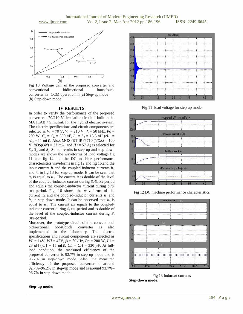
(b)
Fig 10 Voltage gain of the proposed converter and
conventional bidirectional boost/buck
converter in CCM operation in (a) Step-up mode
(b) Step-down mode
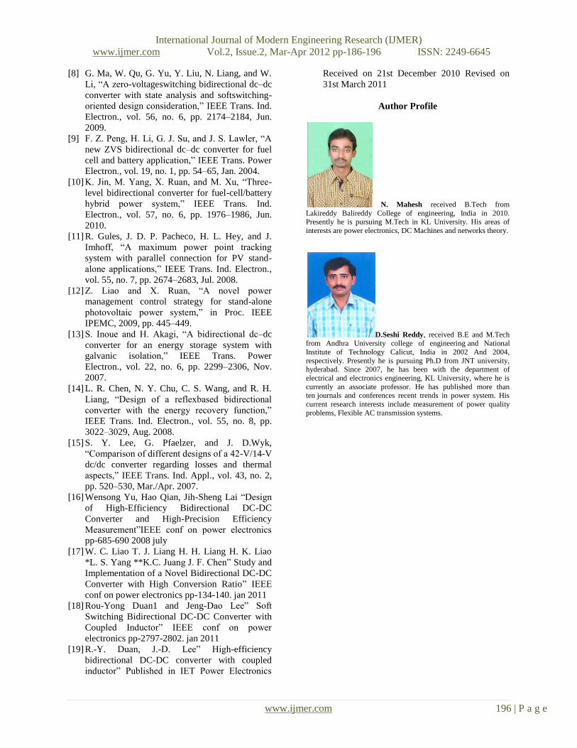
IV RESULTS In order to verify the performance of the proposed
converter, a 70/210-V simulation circuit is built in the
MATLAB / Simulink for the hybrid electric system.
The electric specifications and circuit components are
selected as VL = 70 V, VH = 210 V, fs = 50 kHz, Po =
200 W, CL = CH = 330 μF, L1 = L2 = 15.5 μH (rL1 =
rL2 = 11 mΩ). Also, MOSFET IRF3710 (VDSS = 100
V, RDS(ON) = 23 mΩ, and ID = 57 A) is selected for
S1, S2, and S3. Some results in step-up and step-down
modes are shows the waveforms of load voltage fig
11 and fig 14 and the DC machine performance
characteristics waveforms in fig 12 and fig 15.and the
input current iL and the coupled inductor currents iL1
and iL2 in fig 13 for step-up mode. It can be seen that
iL1 is equal to iL2. The current iL is double of the level
of the coupled-inductor current during S1/S2 ON-period
and equals the coupled-inductor current during S1/S2
OFF-period. Fig. 16 shows the waveforms of the
current iLL and the coupled-inductor currents iL1 and
iL2 in step-down mode. It can be observed that iL1 is
equal to iL2. The current iLL equals to the coupled-
inductor current during S3 ON-period and is double of
the level of the coupled-inductor current during S3
OFF-period.
Moreover, the prototype circuit of the conventional
bidirectional boost/buck converter is also
implemented in the laboratory. The electric
specifications and circuit components are selected as
VL = 14V, VH = 42V, fs = 50kHz, Po = 200 W, L1 =
28 μH (rL1 = 15 mΩ), CL = CH = 330 μF. At full-
load condition, the measured efficiency of the
proposed converter is 92.7% in step-up mode and is
93.7% in step-down mode. Also, the measured
efficiency of the proposed converter is around
92.7%–96.2% in step-up mode and is around 93.7%–
96.7% in step-down mode
Step-up mode:
Fig 11 load voltage for step up mode
Fig 12 DC machine performance characteristics
Fig 13 Inductor currents
Step-down mode:

International Journal of Modern Engineering Research (IJMER)
www.ijmer.com Vol.2, Issue.2, Mar-Apr 2012 pp-186-196 ISSN: 2249-6645
www.ijmer.com 195 | P a g e
Fig 14 load voltage for step up mode
Fig 15 DC machine performance characteristics
Fig 16 inductor currents
V CONCLUSION This paper researches a novel bidirectional dc–dc
converter drive. The circuit configuration of the
proposed converter is very simple. The proposed
converter has higher step-up and step-down voltage
gains and lower average value of the switch current
than the conventional bidirectional boost/buck
converter which drives the hybrid vehicle. From the
simulation results, it is see that the waveforms agree
with the operating principle and steady-state analysis.
At full-load condition, the measured efficiency is
92.7% in stepup mode and is 93.7% in step-down
mode. Also, the measured efficiency is around
92.7%–96.2% in step-up mode and is around 93.7%–
96.7% in step-down mode, which are higher than the
conventional bidirectional boost/buck converter
drive.
VI REFERENCES
[1] M. B. Camara, H. Gualous, F. Gustin, A.
Berthon, and B. Dakyo, ―DC/DC converter
design for supercapacitor and battery power
management in hybrid vehicle applications—
Polynomial control strategy,‖ IEEE Trans. Ind.
Electron., vol. 57, no. 2, pp. 587–597, Feb. 2010.
[2] T. Bhattacharya, V. S. Giri, K. Mathew, and L.
Umanand, ―Multiphase bidirectional flyback
converter topology for hybrid electric vehicles,‖
IEEE Trans. Ind. Electron., vol. 56, no. 1, pp.
78–84, Jan. 2009.
[3] Z. Amjadi and S. S. Williamson, ―A novel
control technique for a switched-capacitor-
converter-based hybrid electric vehicle energy
storage system,‖ IEEE Trans. Ind. Electron., vol.
57, no. 3, pp. 926–934,Mar. 2010.
[4] F. Z. Peng, F. Zhang, and Z. Qian, ―A magnetic-
less dc–dc converter for dual-voltage automotive
systems,‖ IEEE Trans. Ind. Appl., vol. 39, no. 2,
pp. 511–518, Mar./Apr. 2003.
[5] A. Nasiri, Z. Nie, S. B. Bekiarov, and A. Emadi,
―An on-line UPS system with power factor
correction and electric isolation using BIFRED
converter,‖ IEEE Trans. Ind. Electron., vol. 55,
no. 2, pp. 722–730, Feb. 2008.
[6] L. Schuch, C. Rech, H. L. Hey, H. A. Grundling,
H. Pinheiro, and J. R. Pinheiro, ―Analysis and
design of a new high-efficiency bidirectional
integrated ZVT PWM converter for DC-bus and
battery-bank interface,‖IEEE Trans. Ind. Appl.,
vol. 42, no. 5, pp. 1321–1332, Sep./Oct. 2006.
[7] X. Zhu, X. Li, G. Shen, and D. Xu, ―Design of
the dynamic power compensation for PEMFC
distributed power system,‖ IEEE Trans. Ind.
Electron., vol. 57, no. 6, pp. 1935–1944, Jun.
2010.
International Journal of Modern Engineering Research (IJMER)
www.ijmer.com Vol.2, Issue.2, Mar-Apr 2012 pp-186-196 ISSN: 2249-6645
www.ijmer.com 196 | P a g e
[8] G. Ma, W. Qu, G. Yu, Y. Liu, N. Liang, and W.
Li, ―A zero-voltageswitching bidirectional dc–dc
converter with state analysis and softswitching-
oriented design consideration,‖ IEEE Trans. Ind.
Electron., vol. 56, no. 6, pp. 2174–2184, Jun.
2009.
[9] F. Z. Peng, H. Li, G. J. Su, and J. S. Lawler, ―A
new ZVS bidirectional dc–dc converter for fuel
cell and battery application,‖ IEEE Trans. Power
Electron., vol. 19, no. 1, pp. 54–65, Jan. 2004.
[10] K. Jin, M. Yang, X. Ruan, and M. Xu, ―Three-
level bidirectional converter for fuel-cell/battery
hybrid power system,‖ IEEE Trans. Ind.
Electron., vol. 57, no. 6, pp. 1976–1986, Jun.
2010.
[11] R. Gules, J. D. P. Pacheco, H. L. Hey, and J.
Imhoff, ―A maximum power point tracking
system with parallel connection for PV stand-
alone applications,‖ IEEE Trans. Ind. Electron.,
vol. 55, no. 7, pp. 2674–2683, Jul. 2008.
[12] Z. Liao and X. Ruan, ―A novel power
management control strategy for stand-alone
photovoltaic power system,‖ in Proc. IEEE
IPEMC, 2009, pp. 445–449.
[13] S. Inoue and H. Akagi, ―A bidirectional dc–dc
converter for an energy storage system with
galvanic isolation,‖ IEEE Trans. Power
Electron., vol. 22, no. 6, pp. 2299–2306, Nov.
2007.
[14] L. R. Chen, N. Y. Chu, C. S. Wang, and R. H.
Liang, ―Design of a reflexbased bidirectional
converter with the energy recovery function,‖
IEEE Trans. Ind. Electron., vol. 55, no. 8, pp.
3022–3029, Aug. 2008.
[15] S. Y. Lee, G. Pfaelzer, and J. D.Wyk,
―Comparison of different designs of a 42-V/14-V
dc/dc converter regarding losses and thermal
aspects,‖ IEEE Trans. Ind. Appl., vol. 43, no. 2,
pp. 520–530, Mar./Apr. 2007.
[16] Wensong Yu, Hao Qian, Jih-Sheng Lai ―Design
of High-Efficiency Bidirectional DC-DC
Converter and High-Precision Efficiency
Measurement‖IEEE conf on power electronics
pp-685-690 2008 july
[17] W. C. Liao T. J. Liang H. H. Liang H. K. Liao
*L. S. Yang **K.C. Juang J. F. Chen‖ Study and
Implementation of a Novel Bidirectional DC-DC
Converter with High Conversion Ratio‖ IEEE
conf on power electronics pp-134-140. jan 2011
[18] Rou-Yong Duan1 and Jeng-Dao Lee‖ Soft
Switching Bidirectional DC-DC Converter with
Coupled Inductor‖ IEEE conf on power
electronics pp-2797-2802. jan 2011
[19] R.-Y. Duan, J.-D. Lee‖ High-efficiency
bidirectional DC-DC converter with coupled
inductor‖ Published in IET Power Electronics
Received on 21st December 2010 Revised on
31st March 2011
Author Profile
N. Mahesh received B.Tech from
Lakireddy Balireddy College of engineering, India in 2010. Presently he is pursuing M.Tech in KL University. His areas of
interests are power electronics, DC Machines and networks theory.
D.Seshi Reddy, received B.E and M.Tech from Andhra University college of engineering and National
Institute of Technology Calicut, India in 2002 And 2004,
respectively. Presently he is pursuing Ph.D from JNT university, hyderabad. Since 2007, he has been with the department of
electrical and electronics engineering, KL University, where he is
currently an associate professor. He has published more than
ten journals and conferences recent trends in power system. His
current research interests include measurement of power quality
problems, Flexible AC transmission systems.