a novel modular mobile robot prototype for urban search...
TRANSCRIPT
13
A Novel Modular Mobile Robot Prototype for Urban Search and Rescue
Houxiang Zhang1, Wei Wang2, Guanghua Zong2 and Jianwei Zhang1
1University of Hamburg 2Beijing University of Aeronautics and Astronautics
1Germany 2China
1. Introduction
The last few years have witnessed an increasing interest in reconfigurable mobile robotic technologies (Yim, M.; et al., 2000). The applications include the following areas: industrial inspection (Granosik, G.; Hansen, M. G.; Borenstein, J. 2005), conducting surveillance, urban search and rescue, military reconnaissance and space exploration (Yim, M.; et al., 2003). Reconfigurable robots consist of several modules which are able to change the way they are connected. The modular approach enables mobile robots to reconfigure, which is essential for tasks that are difficult for a fixed-shape robot (Kamimura, A.; et al.; 2001). During movement the robot confronts an unstructured environment and handles the uncertainties by reconfiguring its structure (Castano, A.; et al., 2000). The basic requirement for this kind of robotic system moving on rough terrains is extraordinary motion capabilities. The emphasis for discussion of this chapter is on the field of urban search and rescue
(Miller, P.G. 2002) (Takayama, T.; Hirose, S. 2000). The history of human development has
always been a struggle with natural disasters such as earthquakes, storms and floods.
Recently the number of disasters by accidents or terrorism has evidently been increasing too
(Casper, J.; 2002). Urban search and rescue is a domain that involves a great amount of
manpower; and it is quite dangerous and laborious in a hostile environment (Matsuno, F.;
Tadokoro, S. 2004). The development of mobile robots offers an intelligent alternative
solution to the above-mentioned problems. The application of the robotic system can relieve
people of this challenging work and provide an opportunity for robots to play a pivotal
support role, realize automatic manipulation in a complex environment and improve the
level of civil and military technology.
In this chapter, a novel modular reconfigurable mobile robot named JL-I is presented, which
to date consists of three identical modules. After a short survey, the basic functions of a
reconfigurable mobile robot are summarized systematically based on research into work
targets. JL-I features active joints formed by serial and parallel mechanisms which endow
the robot with the ability of changing shapes in three dimensions. With the docking
mechanisms, the modules can connect or disconnect flexibly and automatically. After that
the discussion focuses on the various locomotion capabilities, such as crossing high vertical
www.intechopen.com
Service Robot Applications
216
obstacles and getting self-recovery when the robot is upside-down. The results of a series of
successful on-site tests are given to confirm the principles described above and the robot’s
ability.
2. Reconfigurable robots in literature
In recent years considerable progress has been made in the field of reconfigurable modular robotic systems, which usually comprise three or more rigid segments that are connected by special joints (Rus, D.; Vona, M.; 2000) (Suzuki, Y.; et al. 2006). The common kinematics modes include multiple legs, wheeled and chain-track vehicles. However, the robots with multiple-legs kinematics are too complex due to a structure with many degrees of freedom (Zhang, H.; et al., 2004). These robots do not meet the requirements of miniaturization, flexible and quick movement, so that multi-legs kinematics is rarely adapted. The common characteristics of reconfigurable robotic systems lie in two points. Firstly, the robotics system comprises several similar modules which are independent units with full locomotion functions (Shen, W.; et al. 2006). Secondly, specially designed joints connect individual units to form a more flexible prototype. The first prototype (Hirose et al. 1990) with powered wheels was designed by Hirose and Morishima in 1990, which consists of several vertical cylindrical segments. Another robot with wheels on each module to provide the driving force was developed by Klaassen for the inspection of sewage pipes (Klaassen et al. 1999). A serpentine robot from Takayama and Hirose consists of three segments. Each segment is driven by a pair of tracks, but all tracks are powered simultaneously by a single motor located in the centre segment (Takayama, T.; Hirose, S.; 2000). The special ability of adapting to irregular terrain is passive and provided by springs. KOHGA (Kamegawa, T.; et al. 2004) has recently been developed by IRS in Japan. It consists of eight serially interconnected individual units with two tracks except the first and last modules. Another group of reconfigurable robots features passive modules (Yim, M.; et al. 2001) (Murata, S.; et al. 2002) (Shen. W.; et al. 2002) (Kurokawa, H.; et al. 2003). It can only move after the modules are assembled (Moechel, R.; et al, 2005) (Gonzalez-Gomez, J.; et al. 2005) (Gonzalez-Gomez, J.; et al. 2004). In (Gonzalez-Gomez, J.; et al. 2007), 1D, 2D and 3D chain robots are classified according to their topology. As an example, PolyBot is able to optimize its parts to fit the specific task. Generally, this kind of reconfigurable robots is relatively simple so that the locomotion capability is not as efficient as the above-mentioned kind with powered tracks. However, for urban rescue and search, the fact that the known reconfigurable robots can only assume few configurations due to relatively simple connecting and pose-adjusting mechanisms is a ubiquitous deficiency. For example, the Millibot Train robot from Carnegie Mellon University consists of seven compact segments, which can connect by couplers with one DOF (Brown, H.B.; et al., 2002). A reconfigurable mobile robot designed by M. Park is not able to change its configuration actively (Park, M.; et al., 2004). Another recent module robot (Wang, T.M.; et al., 2005) has only one DOF in its pose-adjusting mechanism. The robot from Université Libre de Bruxelles (Sahin, E.; et al., 2002) has a one-DOF pose-adjusting mechanism and one coupler to change the configuration between the neighboring modules as well. Since 1999 our group has been focusing on the design and development of mobile robots for urban search and rescue purposes. A smart mobile robot was proposed as a flexible mobile
www.intechopen.com
A Novel Modular Mobile Robot Prototype for Urban Search and Rescue
217
platform carrying a CCD camera and other sensors. A more flexible structure with two linked-track vehicles was proposed (Wang, W.; et al. 1999). The structure can be reconfigured so that the robot can move between surfaces standing at an angle of 0 - 90 degrees due to the pitching DOF actuated by the joint to increase the flexibility. The project presented here has the aim of developing an automatic field robot to meet the requirements of high flexibility, robustness.
3. System design and realization
3.1 Design considerations
Urban search and rescue is one important application for mobile robots in a complex environment. The basic functions of urban search and rescue robots include five aspects. (Zhang, H.; et al. 2006a) 1) Locomotion capability is the lowest basic functionality of the robotic system, which includes the following details. The robot works not only indoors but outdoors as well. It should have a flexible mobility in rugged terrain to get to every point in the work space. In order to finish a task in an unstructured environment, the ability to cross high obstacles and span large gaps is indispensable. Sometimes the working environment is very complicated, including not only high steps and deep ditches but also narrow fences and floors cluttered with debris. As a result, the robot should have the capability of adopting different configurations to match various tasks and suit complex environments. 2) Enough intelligence for the discrimination of a variety of obstacle situations: Multiple sensing and control systems are incorporated to handle the uncertainties in a complex environment. Software should be dexterous enough to identify the various geometries and intelligent enough to autonomously reconstruct the environment. Sensor fusion is an important capability since no single sensor can identify all aspects of the environment. 3) Working autonomously with the corresponding effective treatment: As a rescue robot, it should move as fast as possible in order to get real-time information. Once the global task commands are entered by the user, the robot should move while accomplishing the rescue task. Path planning and behavior organization is built on global prior knowledge and local sensory information. 4) No connection with the environment: In order to move freely, it is important for the mobile field robot not to be wired or otherwise connected to the environment. The robot should carry all it needs: onboard power, the controller, and wireless communication. 5) Cooperation ability: The rescue robot is designed to operate with humans. The level of interaction may vary significantly, depending on the robot’s design and on the circumstances. The controlling and monitoring of the robot is achieved through a GUI to allow an effective and user-friendly operation. Usually urban searching and rescuing is based on the cooperation in a team. The given targets will be assigned separately. Every robot should communicate with the others and perform distributed activities.
3.2 Prototype design and realization The proposed mobile system should have various moving modes. The JL-I system consists of three connected, identical modules for crossing grooves, steps, obstacles and traveling in complex environments. Design of the robot includes five parts:
www.intechopen.com
Service Robot Applications
218
1) Design of the independent mobile module which includes movement mechanisms and driving systems; 2) Development of the docking system and the reconfigurable driving mechanisms; 3) Development of the control system; 4) Kinematics analysis; 5) Experimental testing.
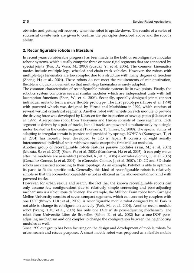
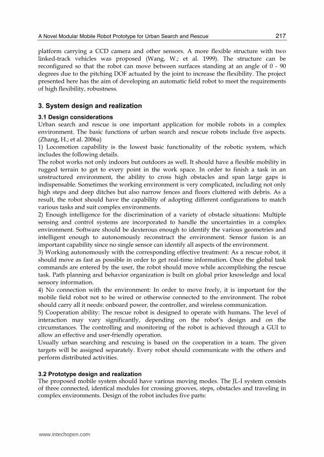
Fig. 1. A photo of JL-I
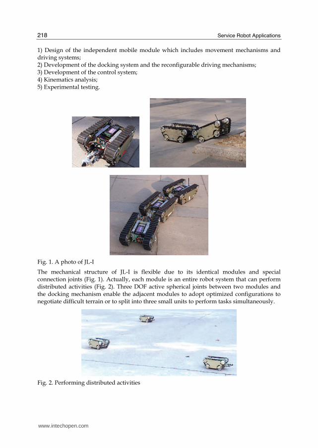
The mechanical structure of JL-I is flexible due to its identical modules and special connection joints (Fig. 1). Actually, each module is an entire robot system that can perform distributed activities (Fig. 2). Three DOF active spherical joints between two modules and the docking mechanism enable the adjacent modules to adopt optimized configurations to negotiate difficult terrain or to split into three small units to perform tasks simultaneously.
Fig. 2. Performing distributed activities
www.intechopen.com
A Novel Modular Mobile Robot Prototype for Urban Search and Rescue
219
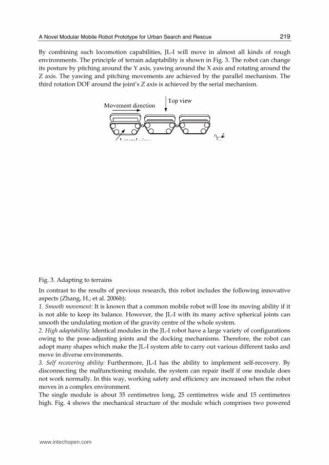
By combining such locomotion capabilities, JL-I will move in almost all kinds of rough
environments. The principle of terrain adaptability is shown in Fig. 3. The robot can change
its posture by pitching around the Y axis, yawing around the X axis and rotating around the
Z axis. The yawing and pitching movements are achieved by the parallel mechanism. The
third rotation DOF around the joint’s Z axis is achieved by the serial mechanism.
Fig. 3. Adapting to terrains
In contrast to the results of previous research, this robot includes the following innovative
aspects (Zhang, H.; et al. 2006b):
1. Smooth movement: It is known that a common mobile robot will lose its moving ability if it
is not able to keep its balance. However, the JL-I with its many active spherical joints can
smooth the undulating motion of the gravity centre of the whole system.
2. High adaptability: Identical modules in the JL-I robot have a large variety of configurations
owing to the pose-adjusting joints and the docking mechanisms. Therefore, the robot can
adopt many shapes which make the JL-I system able to carry out various different tasks and
move in diverse environments.
3. Self recovering ability: Furthermore, JL-I has the ability to implement self-recovery. By
disconnecting the malfunctioning module, the system can repair itself if one module does
not work normally. In this way, working safety and efficiency are increased when the robot
moves in a complex environment.
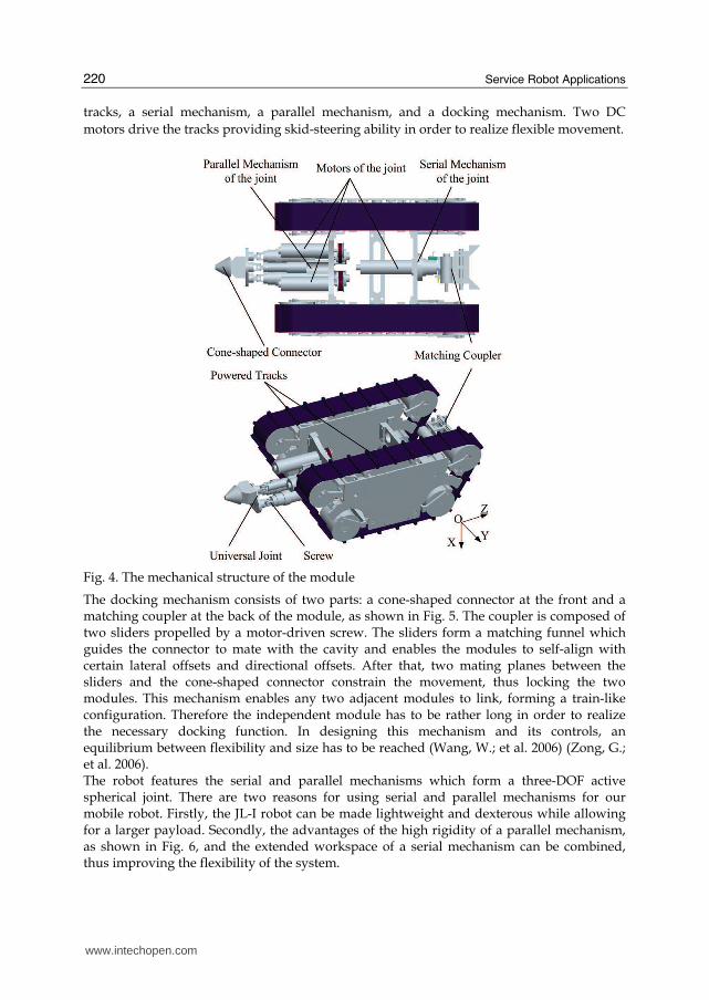
The single module is about 35 centimetres long, 25 centimetres wide and 15 centimetres
high. Fig. 4 shows the mechanical structure of the module which comprises two powered
www.intechopen.com
Service Robot Applications
220
tracks, a serial mechanism, a parallel mechanism, and a docking mechanism. Two DC
motors drive the tracks providing skid-steering ability in order to realize flexible movement.
Fig. 4. The mechanical structure of the module
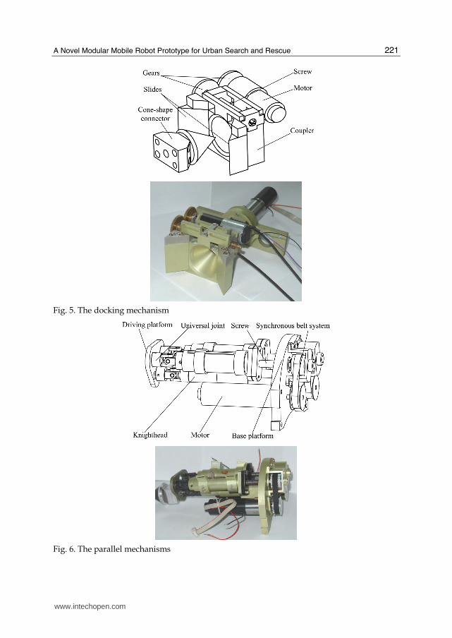
The docking mechanism consists of two parts: a cone-shaped connector at the front and a matching coupler at the back of the module, as shown in Fig. 5. The coupler is composed of two sliders propelled by a motor-driven screw. The sliders form a matching funnel which guides the connector to mate with the cavity and enables the modules to self-align with certain lateral offsets and directional offsets. After that, two mating planes between the sliders and the cone-shaped connector constrain the movement, thus locking the two modules. This mechanism enables any two adjacent modules to link, forming a train-like configuration. Therefore the independent module has to be rather long in order to realize the necessary docking function. In designing this mechanism and its controls, an equilibrium between flexibility and size has to be reached (Wang, W.; et al. 2006) (Zong, G.; et al. 2006). The robot features the serial and parallel mechanisms which form a three-DOF active spherical joint. There are two reasons for using serial and parallel mechanisms for our mobile robot. Firstly, the JL-I robot can be made lightweight and dexterous while allowing for a larger payload. Secondly, the advantages of the high rigidity of a parallel mechanism, as shown in Fig. 6, and the extended workspace of a serial mechanism can be combined, thus improving the flexibility of the system.
www.intechopen.com
A Novel Modular Mobile Robot Prototype for Urban Search and Rescue
221
Fig. 5. The docking mechanism
Fig. 6. The parallel mechanisms
www.intechopen.com
Service Robot Applications
222
The serial mechanism can rotate 360° around the Z axis. This joint is actuated by a geared minimotor which provides a continuous torque of 3.5 Nm at a speed of 30 rpm. The parallel mechanism can pitch around the Y axis and yaw according to the X axis. Each leg of this parallel joint consists of a driving platform, a universal joint, a screw, a synchronous belt system, a DC motor and a base platform. The universal joint connects the driving platform and the knighthead. The other end of the knighthead is fixed to the base platform. By revolving the screw, the driving platform can be manipulated relatively to the base platform. By controlling the active joints and the docking mechanisms, the JL-I can change its shape in three dimensions. To ensure its ability of performing tasks individually, there is enough space in each module
for sensors, the onboard controller, and batteries. Considerable stress is laid on weight
reduction as well as on construction stiffness to achieve a dexterous movement mechanism.
Most of the mechanical parts are designed specifically and mainly manufactured from
aluminium. A module weighs approximately 7 kg including the batteries.
4. Required locomotion capability
Due to the uncertainty of the practical environment, it is important for a robot to be able to
carry out various complicated locomotion processes for performing urban search and rescue
tasks. The JL-I is capable of almost all necessary actions that can be required in real
situations, e.g. crossing obstacles such as steps and roadblocks, self-recovery (Zhang, H.; et
al. 2007).
4.1 Crossing a step
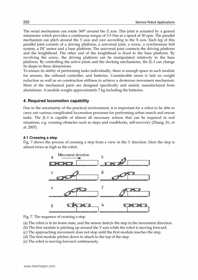
Fig. 7 shows the process of crossing a step from a view in the Y direction. Here the step is
almost twice as high as the robot.
Fig. 7. The sequence of crossing a step
(a) The robot is in its home state, and the sensor detects the step in the movement direction. (b) The first module is pitching up around the Y axis while the robot is moving forward. (c) The approaching movement does not stop until the first module touches the step. (d) The first module pitches down to attach to the top of the step. (e) The robot is moving forward continuously.
www.intechopen.com
A Novel Modular Mobile Robot Prototype for Urban Search and Rescue
223
(f) The robot is moving until the first two modules are attached to the step. (g) The last module is pitching up around the Y axis while the robot is moving forward. (h) The robot is now in its home state again, and the process of crossing the step is over.
4.2 90° self-recovery
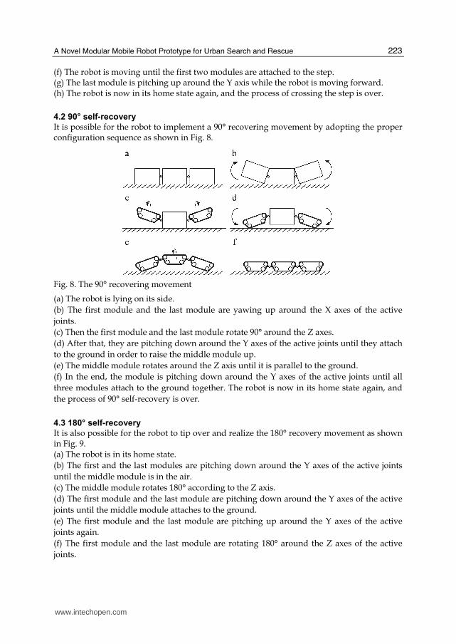
It is possible for the robot to implement a 90° recovering movement by adopting the proper configuration sequence as shown in Fig. 8.
Fig. 8. The 90° recovering movement
(a) The robot is lying on its side.
(b) The first module and the last module are yawing up around the X axes of the active
joints.
(c) Then the first module and the last module rotate 90° around the Z axes.
(d) After that, they are pitching down around the Y axes of the active joints until they attach
to the ground in order to raise the middle module up.
(e) The middle module rotates around the Z axis until it is parallel to the ground.
(f) In the end, the module is pitching down around the Y axes of the active joints until all
three modules attach to the ground together. The robot is now in its home state again, and
the process of 90° self-recovery is over.
4.3 180° self-recovery
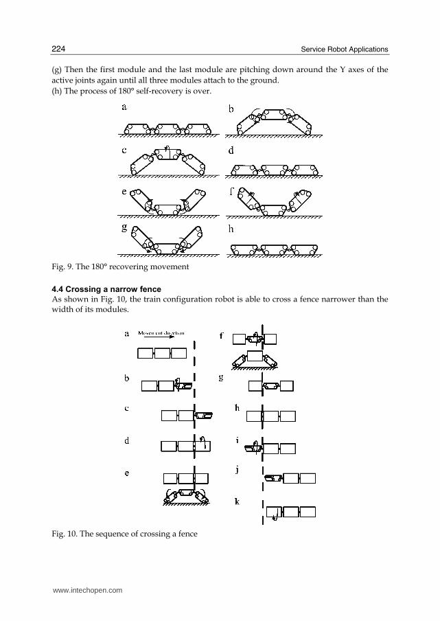
It is also possible for the robot to tip over and realize the 180° recovery movement as shown in Fig. 9. (a) The robot is in its home state.
(b) The first and the last modules are pitching down around the Y axes of the active joints
until the middle module is in the air.
(c) The middle module rotates 180° according to the Z axis.
(d) The first module and the last module are pitching down around the Y axes of the active
joints until the middle module attaches to the ground.
(e) The first module and the last module are pitching up around the Y axes of the active
joints again.
(f) The first module and the last module are rotating 180° around the Z axes of the active
joints.
www.intechopen.com
Service Robot Applications
224
(g) Then the first module and the last module are pitching down around the Y axes of the
active joints again until all three modules attach to the ground.
(h) The process of 180° self-recovery is over.
Fig. 9. The 180° recovering movement
4.4 Crossing a narrow fence
As shown in Fig. 10, the train configuration robot is able to cross a fence narrower than the width of its modules.
Fig. 10. The sequence of crossing a fence
www.intechopen.com
A Novel Modular Mobile Robot Prototype for Urban Search and Rescue
225
(a) The robot is in its home state, and the sensor detects the fence in the moving direction. (b) The robot stops before the fence, and then the first module pitches up around the Y axis and then rotates 90° according to the Z axis. (c) The crossing movement does not stop until the first module passes through the fence. (d) The first module rotates and pitches to get back into the home state, and then the three modules attach to the ground together again. The following steps (e) to (k) of the second and third modules are similar to those of the first
one. The process will be achieved until the robot crosses the fence entirely. In order to show
the principle clearly, the lateral views of steps (e) and (f) are also given.
5. Kinematics analysis
5.1 The DOF of the active joint
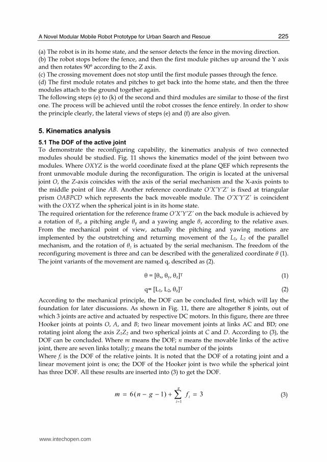
To demonstrate the reconfiguring capability, the kinematics analysis of two connected
modules should be studied. Fig. 11 shows the kinematics model of the joint between two
modules. Where OXYZ is the world coordinate fixed at the plane QEF which represents the
front unmovable module during the reconfiguration. The origin is located at the universal
joint O, the Z-axis coincides with the axis of the serial mechanism and the X-axis points to
the middle point of line AB. Another reference coordinate O’X’Y’Z’ is fixed at triangular
prism OABPCD which represents the back moveable module. The O’X’Y’Z’ is coincident
with the OXYZ when the spherical joint is in its home state.
The required orientation for the reference frame O’X’Y’Z’ on the back module is achieved by
a rotation of θz, a pitching angle θy and a yawing angle θx according to the relative axes.
From the mechanical point of view, actually the pitching and yawing motions are
implemented by the outstretching and returning movement of the L1, L2 of the parallel
mechanism, and the rotation of θz is actuated by the serial mechanism. The freedom of the
reconfiguring movement is three and can be described with the generalized coordinate θ (1).
The joint variants of the movement are named q, described as (2).
θ = [θx, θy, θz]T (1)
q= [L1, L2, θz]T (2)
According to the mechanical principle, the DOF can be concluded first, which will lay the
foundation for later discussions. As shown in Fig. 11, there are altogether 8 joints, out of
which 3 joints are active and actuated by respective DC motors. In this figure, there are three
Hooker joints at points O, A, and B; two linear movement joints at links AC and BD; one
rotating joint along the axis Z1Z2 and two spherical joints at C and D. According to (3), the
DOF can be concluded. Where m means the DOF; n means the movable links of the active
joint, there are seven links totally; g means the total number of the joints
Where fi is the DOF of the relative joints. It is noted that the DOF of a rotating joint and a
linear movement joint is one; the DOF of the Hooker joint is two while the spherical joint
has three DOF. All these results are inserted into (3) to get the DOF.
3)1(61
=+−−= ∑=g
i
ifgnm
(3)
www.intechopen.com
Service Robot Applications
226
Fig. 11 The kinematics mode of the active spherical joint.
5.2 Preliminary analysis of working space
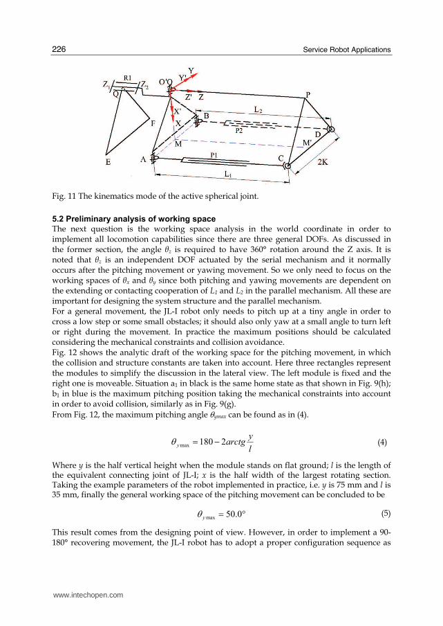
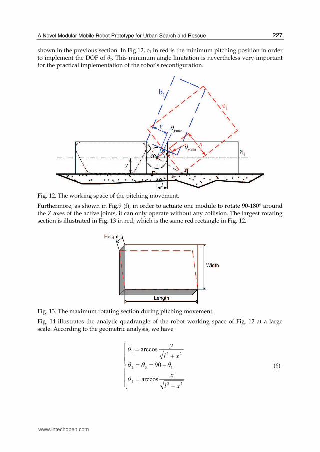
The next question is the working space analysis in the world coordinate in order to implement all locomotion capabilities since there are three general DOFs. As discussed in the former section, the angle θz is required to have 360° rotation around the Z axis. It is noted that θz is an independent DOF actuated by the serial mechanism and it normally occurs after the pitching movement or yawing movement. So we only need to focus on the working spaces of θx and θy since both pitching and yawing movements are dependent on the extending or contacting cooperation of L1 and L2 in the parallel mechanism. All these are important for designing the system structure and the parallel mechanism. For a general movement, the JL-I robot only needs to pitch up at a tiny angle in order to cross a low step or some small obstacles; it should also only yaw at a small angle to turn left or right during the movement. In practice the maximum positions should be calculated considering the mechanical constraints and collision avoidance. Fig. 12 shows the analytic draft of the working space for the pitching movement, in which the collision and structure constants are taken into account. Here three rectangles represent the modules to simplify the discussion in the lateral view. The left module is fixed and the right one is moveable. Situation a1 in black is the same home state as that shown in Fig. 9(h); b1 in blue is the maximum pitching position taking the mechanical constraints into account in order to avoid collision, similarly as in Fig. 9(g).
From Fig. 12, the maximum pitching angle θymax can be found as in (4).
l
yarctgy 2180max −=θ
(4)
Where y is the half vertical height when the module stands on flat ground; l is the length of the equivalent connecting joint of JL-I; x is the half width of the largest rotating section. Taking the example parameters of the robot implemented in practice, i.e. y is 75 mm and l is 35 mm, finally the general working space of the pitching movement can be concluded to be
°0.50max =yθ (5)
This result comes from the designing point of view. However, in order to implement a 90-180° recovering movement, the JL-I robot has to adopt a proper configuration sequence as
www.intechopen.com
A Novel Modular Mobile Robot Prototype for Urban Search and Rescue
227
shown in the previous section. In Fig.12, c1 in red is the minimum pitching position in order to implement the DOF of θz. This minimum angle limitation is nevertheless very important for the practical implementation of the robot’s reconfiguration.
Fig. 12. The working space of the pitching movement.
Furthermore, as shown in Fig.9 (f), in order to actuate one module to rotate 90-180° around the Z axes of the active joints, it can only operate without any collision. The largest rotating section is illustrated in Fig. 13 in red, which is the same red rectangle in Fig. 12.
Fig. 13. The maximum rotating section during pitching movement.
Fig. 14 illustrates the analytic quadrangle of the robot working space of Fig. 12 at a large scale. According to the geometric analysis, we have
⎪⎪⎪⎩
⎪⎪⎪⎨⎧
+=−==
+=
224
132
221
arccos
90
arccos
xl
x
xl
y
θθθθ
θ
(6)
www.intechopen.com

Service Robot Applications
228
)90(9090 1434min θθθθθ −−−=−−=
2222
41 arccosarccosxl
x
xl
y
+−+=−= θθ (7)
2 2
/ 2
x Height Width
y Height
⎧ = +⎪⎨ =⎪⎩ (8)
Fig. 14. The analytic quadrangle of the working space.
Given the height and width of the module, putting (8) into (7) we can get the minimum
working space of the pitching DOF for robotic runtime reconfiguration in order to avoid
collisions. Finally the working space for θy is as in (9).
2 2 2 2
2 2 2 2
[ (180 2 ), (arccos arccos ) ]
(arccos arccos ), (180 2 )]
y
y y xarctg
l l x l x
y x yarctg
ll x l x
θ ∈ − − − −+ ++ − + −+ +
U (9)
Similarly for the working space of the yawing movement, θx can be also described like θy (9)
while y is the half width of the module at the moment. According to the prototype structure,
the pitching and yawing working spaces are obtained. As in our implementation, when the
module width is 250 mm, the height is 150 mm and l is 35 mm, the general working space is
described in (10); while the restricted working space for avoiding collision is (11)
⎩⎨⎧
°+°−∈°+°−∈
]0.50,0.50[
]32,0.32[
y
xθθ
(10)
www.intechopen.com
A Novel Modular Mobile Robot Prototype for Urban Search and Rescue
229
⎩⎨⎧
°+°+°−°−∈°+°+°−°−∈
]0.50,0.24[]0.24,0.50[
]0.32,0.8[]0.8,0.32[
U
U
y
xθθ
(11)
In order to simplify the mechanical structure, we can design the working space of θx, θy to be
the same, e.g. both within -50 to 50 degrees, which not only reduces the implementation cost
but also slightly increases redundancy for practical operation (Zhang, H.; et al. 2007).
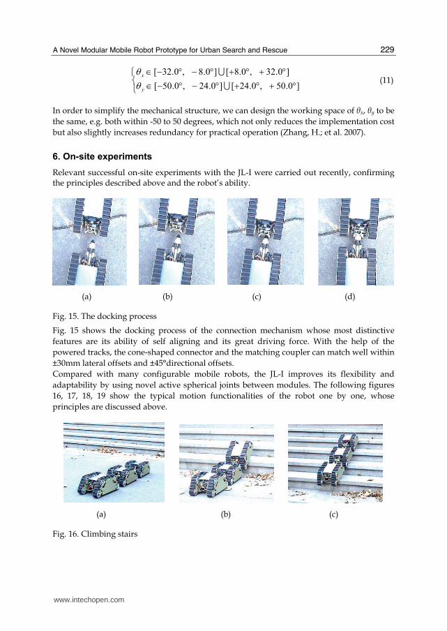
6. On-site experiments
Relevant successful on-site experiments with the JL-I were carried out recently, confirming the principles described above and the robot’s ability.
(a) (b) (c) (d)
Fig. 15. The docking process
Fig. 15 shows the docking process of the connection mechanism whose most distinctive
features are its ability of self aligning and its great driving force. With the help of the
powered tracks, the cone-shaped connector and the matching coupler can match well within
±30mm lateral offsets and ±45°directional offsets.
Compared with many configurable mobile robots, the JL-I improves its flexibility and
adaptability by using novel active spherical joints between modules. The following figures
16, 17, 18, 19 show the typical motion functionalities of the robot one by one, whose
principles are discussed above.
(a) (b) (c)
Fig. 16. Climbing stairs
www.intechopen.com
Service Robot Applications
230
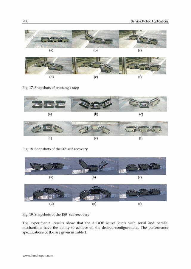
(a) (b) (c)
(d) (e) (f)
Fig. 17. Snapshots of crossing a step
(a) (b) (c)
(d) (e) (f)
Fig. 18. Snapshots of the 90° self-recovery
(a) (b) (c)
(d) (e) (f)
Fig. 19. Snapshots of the 180° self-recovery
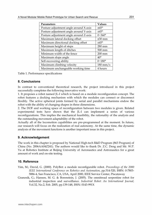
The experimental results show that the 3 DOF active joints with serial and parallel
mechanisms have the ability to achieve all the desired configurations. The performance
specifications of JL-I are given in Table 1.
www.intechopen.com
A Novel Modular Mobile Robot Prototype for Urban Search and Rescue
231
Parameters Values
Posture adjustment angle around X-axis ±45°
Posture adjustment angle around Y-axis ±45°
Posture adjustment angle around Z-axis 0~360°
Maximum lateral docking offset ±30 mm
Maximum directional docking offset ±45°
Maximum height of steps 280 mm
Maximum length of ditches 500 mm
Minimum width of the fence 200 mm
Maximum slope angle 40°
Self-recovering ability 0~180°
Maximum climbing velocity 180 mm/s
Maximum unchangeable working time 4 hours
Table 1. Performance specifications
8. Conclusions
In contrast to conventional theoretical research, the project introduced in this project successfully completes the following innovative work: 1. It proposes a robot named JL-I which is based on a module reconfiguration concept. The robot features a docking mechanism with which the modules can connect or disconnect flexibly. The active spherical joints formed by serial and parallel mechanisms endow the robot with the ability of changing shapes in three dimensions. 2. The DOF and working space of reconfiguration between two modules is given. Related experimental tests have shown that the JL-I can implement a series of various reconfigurations. This implies the mechanical feasibility, the rationality of the analysis and the outstanding movement adaptability of the robot. Actually all of the locomotion capabilities are pre-programmed at the moment. In future, our research will focus on the realization of real autonomy. At the same time, the dynamic analysis of the movement functions is another important issue in this project.
9. Acknowledgement
The work in this chapter is proposed by National High-tech R&D Program (863 Program) of China (No. 2006AA04Z241). The authors would like to thank Dr. Z.C. Deng and Mr. W.P. Yu at Robotics Institute at Beijing University of Aeronautics and Astronautics for a great amount of work and on-site testing.
10. Reference
Yim, M.; David, G. (2000). PolyBot: a module reconfigurable robot. Proceedings of the 2000 IEEE International Conference on Robotics and Automation, pp.514-520, ISBN: 0-7803-5886-4, San Francisco, CA, USA, April 2000, IEEE Service Center, Piscataway
Granosik, G.; Hansen, M. G. & Borenstein, J. (2005). The omnitread serpentine robot for industrial inspection and surveillance. Industrial Robot: An International Journal, Vol.32, No.2, Feb. 2005, pp.139-148, ISSN: 0143-991X
www.intechopen.com
Service Robot Applications
232
Yim, M.; Roufas, K.; Duff, D.; Zhang, Y.; Eldershaw, C. & Homans, S. (2003). Module Reconfigurable Robot in Space Application, Autonomous Robots, Vol. 14, Issue 2-3, 2003, pp.225-237, ISSN: 0929-5593.
Kamimura, A.; Kurokawa, H.; Yoshida, E.; Murata, S.; Tomita, K. & Kokaji, S. (2005). Automatic locomotion design and experiments for a modularrobotic system, IEEE/ASME Transactions on Mechatronics, Vol. 10, No. 3, March 2005, pp.314-325, ISSN: 1083-4435
Castano, A.; Shen, W.M. & Will, P. (2000). CONRO: towards miniature self-sufficient metamorphic robots. Autonomous Robots, Vol.13, No.4, April 2000, pp.309-324, ISSN: 0929-5593
Miller, P.G. (2002). Snake robots for search and rescue, In: Neurotechnology for Biomimetic Robots. Ayers, J.; Davis, L.; Rudolph, A. (Ed.), pp. 271-284, 2002, MIT Press, ISBN-13:978-0-262-01193-8.
Takayama, T. & Hirose, S. (2000). Development of Souryu-I connected crawler vehicle for inspection of narrow and winding space, Proceedings of the 26th Annual Conference of the IEEE Industrial Electronics Society, pp. 143-148 ISBN: 0-7803-6456-2, Nagoya, Aichi, Japan, Oct. 2000, IEEE Service Center, Piscataway
Matsuno, F.; Tadokoro, S. (2004). Rescue Robots and Systems in Japan. Proceedings of Robio2004, pp.12-20, ISBN: 0-7803-8614-8, Shenyang, China, 22-26 Aug. 2004, IEEE Service Center, Piscataway.
Casper, J. (2002). Human-Robot Interactions during the Robot-assisted Urban Search and Rescue Response at the World Trade Center, MS Thesis, Computer Science and Engineering, USF, April, 2002.
Rus, D.; Vona, M. (2000). A basis for self reconfigurable robots using crystal modules, Proceedings of the 2000 IEEE Conference on Intelligent Robots and Systems, pp. 2194-2202, ISBN: 0-7803-6348-5 Takamatsu, Japan, October 2000, IEEE Service Center, Piscataway
Suzuki, Y.; Inou, N.; Kimura, H. & Koseki, M. (2006). Reconfigurable group robots adaptively transforming a mechanical structure – Crawl motion and adaptive transformation with new algorithms. Proceedings of IEEE International Conference on Intelligent Robots and Systems, pp. 2200-2205, ISBN: 1-4244-0259-X, Beijing, China, October 2006, IEEE Service Center, Piscataway
Zhang, H.; Zhang, J.; Zong, G. (2004). Requirements of glass cleaning and development of climbing robot systems, Proceedings of the 2004 International Conference on Intelligent Mechatronics and Automation, pp. 101-106, ISBN: 0-7803-8748-1, Chengdu, China, August 26-31, 2004, IEEE Service Center, Piscataway.
Shen, W.; Krivokon, M.; Chiu, H.; Everist, J. & Rubenstein, M. (2006). Multimode Locomotion via SuperBot Reconfigurable Robots. Autonomous Robots, Vol.20, 2006, pp165-177, ISSN: 0929-5593
Hirose, S. & Morishima, A. (1990). Design and control of a mobile robot with an articulated body. The International Journal of Robotics Research, Vol. 9 No. 2, Feb. 1990. pp.99-113, ISSN: 0278-3649
Klaassen, B. & Paap, K.L. (1999). GMD-SNAKE2: a snake-like robot driven by wheels and a method for motion control. Proceedings of the 1999 IEEE International Conference on Robotics and Automation, pp. 3014 - 3019, ISBN: 0792356012, Detroit, MI, USA, May 1999, IEEE Service Center, Piscataway
www.intechopen.com
A Novel Modular Mobile Robot Prototype for Urban Search and Rescue
233
Takayama, T.; Hirose, S. (2000). Development of Souryu-I connected crawler vehicle for inspection of narrow and winding space, Proceeding of the 26th Annual Conference of the IEEE Industrial Electronics Society, Vol.1, pp.143-148, ISBN: 0-7803-6456-2, Nagoya, Japan, Oct, 2000, IEEE Service Center, Piscataway.
Kamegawa, T.; Yamasaki, T.; Igarashi, H.; and Matsuno, F.(2004). Development of the Snake-like Rescue Robot “KOHGA”, Proceedings of the 2004 IEEE International Conference on Robotics and Automation, pp. 5081-5086, ISSN: 1050-4729,ISBN: 0-7803-8232-3, New Orleans, LA, USA, April-May, 2004, IEEE Service Center, Piscataway.
Yim, M.; Zhang, Y.; Mao, E. (2001). Distributed control for 3D shape Metamorphosis, Autonomous Robots, Vol.10, No.1, pp.41-56, 2001, ISSN: 0929-5593.
Murata, S.; Yoshida, E.; Kamimura, A.; Kurokawa, H.; Tomita, K.; Kokaji, S. (2002). M-TRAN:Self-Reconfigurable Module Robotic System, IEEE/ASME Transactions on Mechatronics, Vol.7, No.4, pp.431-441, 2002, ISSN: 1083-4435.
Shen, W.; Salemi B. & Will, P. (2002). Hormone-Inspired adaptive communication and distributed control for CONRO self-reconfigurable robots. IEEE Transactions on Robotics and Automation, Vol. 18, No. 4, Oct. 2002, pp.700-712, ISSN: 0882-4967
Kurokawa, H.; Kamimura, A.; Yoshida, E.; Tomita, K. & Kokaji, S. (2003). M-TRAN II: Metamorphosis from a Four-Legged Walker to a Caterpillar. Proceedings of the 2003 IEEE/RSJ Intl. Conference on Intelligent Robots and Systems, pp. 2454-2459, ISBN: 0-7803-7860-1, October 2003, Las Vegas, Nevada, IEEE Service Center, Piscataway.
Moechel, R.; Jaquier, C.; Drapel K., Dittrich E. & Upegui A. (2005). Yamor and Bluemove-an Autonomous Modular Robot with Bluetooth Interface for Exploring Adaptive Locomotion, Proceeding of the 8th International Conference on Climbing and Walking Robots, CLAWAR 2005, pp. 685-692, ISBN: 978-3-540-26413-2,September, 2005, London, U.K. Springer Berlin Heidelberg.
Gonzalez-Gomez J.; Aguayo, E; & Boemo, E. (2004). Locomotion of a Modular Worm-like Robot using a FPGA-based embedded MicroBlaze Soft-processor. Proceeding of the 7th International Conference on Climbing and Walking Robots, CLAWAR 2004, pp. 869-878, ISBN: 3540229922, September, 2004, Madrid, Spain, Springer.
Gonzalez-Gomez, J. & Boemo E., (2005). Motion of Minimal Configurations of a Modular Robot: Sinusoidal, Lateral Rolling and Lateral Shift, Proceeding of the 8th International Conference on Climbing and Walking Robots, CLAWAR 2005, pp. 667-674, ISBN: 978-3-540-26413-2,September, 2005, London, U.K. Springer Berlin Heidelberg.
Gonzalez-Gomez, J.; H. Zhang, Boemo, E. (2007). Locomotion Principles of 1D Topology Pitch and Pitch-Yaw-Connecting Modular Robots, In: Bioinspiration and Robotics: Walking and Climbing Robots, Habib, Maki K (Ed.), pp.403-428. Advanced Robotic System and I-Tech, ISBN:978-3-902613-15-8.
Brown, H. B. & et al. (2002). Millibot trains for enhanced mobility. IEEE/ASME Transactions on Mechantronics, Vol.7, No.4, March 2002, pp.452-461, ISSN: 1083-4435
Park, M.; Chung W. & Yim M. (2004). Control of a mobile robot with passive multiple trailers. Proceedings of the 2004 IEEE International Conference on Robotics and Automation, pp. 4369-4374, ISBN: 0-7803-8232-3, New Orleans, LA, United States, April-May 2004, IEEE Service Center, Piscataway
Wang, T.; Zou, D.; Chen, D. (2005). Mechanism design and control method of reconfigurable tracked robot, Journal of Beijing University of Aeronautics and Astronautics, Vol.32, No.7, pp. 705-708, ISSN: 1001-5965.
www.intechopen.com
Service Robot Applications
234
Sahin, E.; Labella, T.H. & et al. (2002). SWARM-BOT: Pattern formation in a swarm of self-assembling mobile robots. Proceedings of the 2002 IEEE International Conference on Systems, Man and Cybernetics, pp. 145-150, ISBN: 0-7803-7437-1, Yasmine Hammamet, Tunisia, October 2002, IEEE Service Center, Piscataway
Wang, W.; Zong, G. (1999) Analysis on the Mechanics Stability for a New Kind of Robot, Journal of Robot, Vol.21, No.7, pp. 642-648, ISSN: 1002-0446.
Zhang, H.; Wang, W.; Deng, Z.C. & Zong, G.H. (2006a). A novel reconfigurable robot for urban search and rescue. International Journal of Advanced Robotic Systems, Vol.3 No.4, 2006, PP.259-366, ISSN: 1729-8806
Zhang, H.; Deng, Z.; Wang, W.; Zhang, J. & Zong, G. (2006b). Locomotion Capabilities of a Novel Reconfigurable Robot with 3 DOF Active Joints for Rugged Terrain, Proceedings of the 2006 IEEE/RSJ International Conference on Intelligent Robots and Systems, IROS 2006, pp.5588-5593, Beijing, China, October, 2006
Wang, W.; Zhang H.X; Zong, G.H. & Zhang, J.W. (2006). Design and realization of a novel reconfigurable robot with serial and parallel mechanisms. Proceedings of 2006 IEEE International Conference on Robotics and Biomimetics, pp. 697-702, ISBN: 1-4244-0571-8, Kunming, China, Dec. 2006, IEEE Service Center, Piscataway
Zong, G.; Deng, Z.; & Wang, W. (2006) Realization of a Modular Reconfigurable Robot for Rough Terrain, Proceedings of the 2006 IEEE International Conference on Mechatronics and Automation, pp. 289-294, ISBN: 1-4244-0466-5 Luoyang, Henan, China, June,2006, , IEEE Service Center, Piscataway.
Zhang, H.; Chen, S.; Wang, W.; Zhang, J. & Zong, G. (2007). Runtime Reconfiguration of a Modular Mobile Robot with Serial and Parallel Mechanisms, 2007 IEEE/RSJ International Conference on Intelligent Robots and Systems, pp.2999-3004, ISBN: 1-4244-0912-8, San Diego, CA, USA, Oct. 29 – Nov. 2, 2007, IEEE Service Center, Piscataway
www.intechopen.com
Service Robot ApplicationsEdited by Yoshihiko Takahashi
ISBN 978-953-7619-00-8Hard cover, 400 pagesPublisher InTechPublished online 01, August, 2008Published in print edition August, 2008
InTech EuropeUniversity Campus STeP Ri Slavka Krautzeka 83/A 51000 Rijeka, Croatia Phone: +385 (51) 770 447 Fax: +385 (51) 686 166www.intechopen.com
InTech ChinaUnit 405, Office Block, Hotel Equatorial Shanghai No.65, Yan An Road (West), Shanghai, 200040, China
Phone: +86-21-62489820 Fax: +86-21-62489821
The aim of this book is to provide new ideas, original results and practical experiences regarding servicerobotics. This book provides only a small example of this research activity, but it covers a great deal of whathas been done in the field recently. Furthermore, it works as a valuable resource for researchers interested inthis field.
How to referenceIn order to correctly reference this scholarly work, feel free to copy and paste the following:
Houxiang Zhang, Wei Wang, Guanghua Zong and Jianwei Zhang (2008). A Novel Modular Mobile RobotPrototype for Urban Search and Rescue, Service Robot Applications, Yoshihiko Takahashi (Ed.), ISBN: 978-953-7619-00-8, InTech, Available from:http://www.intechopen.com/books/service_robot_applications/a_novel_modular_mobile_robot_prototype_for_urban_search_and_rescue

© 2008 The Author(s). Licensee IntechOpen. This chapter is distributedunder the terms of the Creative Commons Attribution-NonCommercial-ShareAlike-3.0 License, which permits use, distribution and reproduction fornon-commercial purposes, provided the original is properly cited andderivative works building on this content are distributed under the samelicense.