a novel method of coordinating psss and facts devices … · a novel method of coordinating psss...
TRANSCRIPT
A novel method of coordinating PSSs and FACTS Devices in Power System Stability Enhancement
M. Ahmadzadeh S. S. Mortazavi A. Saeedian Elect. Engg Dept., Shahid Chamran University
Abstract— this paper shows the effect of power system
Stabilizers (PSS) and Flexible AC Transmission Systems (FACTS devices) based stabilizers containing Thyristor controlled Series Compensator (TCSC), Static var compensators (SVC), Thyristor Controlled and phase shifter (TCPS) on stability of power systems. Moreover this paper presents a novel approach for designing coordinated controllers of PSS and FACTS such as coordination of PSS with SVC, PSS with TCSC and PSS with TCPS for enhancing small disturbance stability. The coordinated control problem is formulated as a constrained optimization with eigenvalue-based objective function .The proposed approach employs genetic algorithm (GA) for optimization. To study the effectiveness of the proposed controllers, three different loading conditions including light, normal and heavy loading conditions are considered. Moreover in order to determine effect of proposed design, three case studies are considered too. These include: 1-without compensation (base case), 2-single compensation and 3-coordinated compensation.
Simulation results show that the controller design approach is able to provide better damping and stability performance.
Index Terms- Power system stabilizer, PSS, FACTS devices, SVC, TCSC, TCPS, Optimization, coordinated design, small disturbance stability.
Ι.INTRODUCTION
The line impedance, the receiving and sending ends
voltages, and phase angle between these voltages determine the rate of electrical power transmission over an electric line. Hence, controlling, one or few of the transmitted power factors; it is possible to control the active as well as the reactive power flow over a line.
Series and shunt capacitor, and phase shifter are different approaches to increase the power transmission capacity of lines. Even traditionally used but all these were relatively slow but very useful in a steady state operation of power systems. From a dynamical point of view, their time response is too slow to effectively damp transient oscillations. If mechanically controlled systems were made to respond faster, power system security would be significantly improved, allowing the full utilization of system capability while maintaining adequate levels of stability. This concept and advances in the field of power electronics led to a new approach introduced by the Electric Power Research Institute (EPRI) in the late 1980. Called Flexible AC Transmission Systems or simply FACTS, it was an answer to a call for a more efficient use of already existing resources of power systems while maintaining and even improving power system stability.
Damping of electromechanical oscillations among interconnected synchronous generators is necessary for secure system operation. Power system stabilizer (PSS) has been used for many years to damp out the oscillations [1]. With this way of increasing transmission line loading over long distances, then use of PSS in some cases may not provide sufficient damping for inter-area oscillations. In such cases, in addition to PSS, other effective alternatives are needed.
In particular, FACTS device stabilizers have been proposed to augment the main control systems for the purpose of damping the rotor modes or inter-area modes of oscillation.
However, to achieve an optimal small-disturbance performance and transient state stability improvement, the co-ordination between PSSs and FACTS devices controllers is necessary.
A procedure was previously reported for simultaneous co-ordination of PSSs and FACTS devices to enhance the damping of the rotor modes [2], [4]. The procedure [2] determines only the stabilizer gains based on the approximation that ‘the shift in the rotor mode eigenvalue is linearly related to the increments in stabilizer gains’. In that paper [2], a systematic and optimal control coordinate design procedure between PSSs and FACTS devices such as static VAR compensator (SVC) is developed. The controllers design problem is transformed into a constrained optimization problem (i.e. search for optimal settings of controller parameters). The design is based on the minimization of the real parts of eigenvalues, including those of the rotor modes, and eigenvalues of the state matrix of the power system to enhance its small disturbance stability. The alternative design is based on the minimization of stabilizer gains with constraints imposed on selected eigenvalues.
But in this paper for increment of damping of electromechanical mode and to improve small disturbance stability, a lead-lag controller is also used. This controller is shown in figs.1-4. In these controllers, in addition to stabilizer gains, time constants including T1, T2, T3 and T4 optimized using genetic algorithm. To study the effectiveness of the proposed controllers, three different loading conditions including light, normal and heavy loading conditions are considered.
In order to determine the effectiveness of proposed design three case studies are considered: 1-without compensation (base case), 2-single compensation and 3-coordinated compensation.
WSEAS TRANSACTIONS on POWER SYSTEMS M. Ahmadzadeh, S. S. Mortazavi, A. Saeedian
ISSN: 1790-5060 177 Issue 5, Volume 4, May 2009
Simulation results show that the controller design approach is able to provide better damping and stability performance.
II.MODEL OF POWER SYSTEM ELEMENTS
A. Generator model
The generator is represented by the 3rd order model consisting of the swing equation and the generator internal voltage equation. The swing equation can be written as [5]:
( 1−=
•
ωωδ b ) (1)
( )( ) MDPP em /1−−−=•
ωω (2) The internal voltage, Eq’, is given by
=•
qE ( )( ) doqdddfd TEixxE /−′−− (3)
B. Excitation system model
( )( ) AfdpssrefAfd TEuvVKE /−+−=•
(4)
( 2/122qd vvv += ) (5)
qqd ixv = (6)
ddqqddqq ixEvixEv ′−=′−= (7)
Where is the reference voltage, v is the terminal
voltage, and id, iq are d- and q-axis armature current and vd, vq are d- and q-axis terminal voltage xd’ is d-axis transient reactance and xq is Generator q-axis reactance.
refV
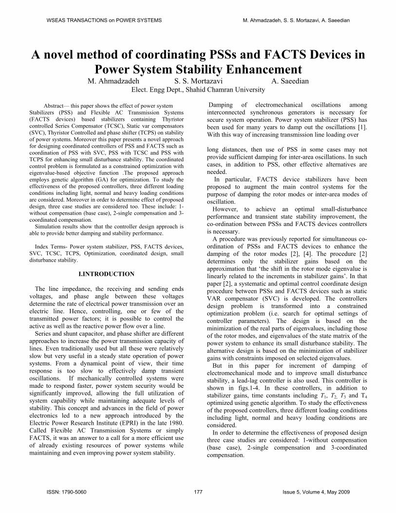
Fig.1:typeST1 excitation system with PSS. [6]
C. Damping Controller Model of PSS A conventional lead-lag PSS is installed in the feedback
loop to generate a supplementary stabilizing signal , see Fig. 1. The PSS input is the change in the machine speed.
pssu
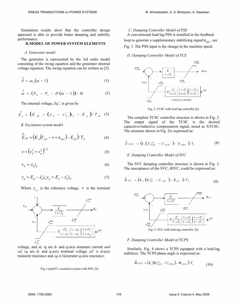
D. Damping Controller Model of TCS
Fig. 2: TCSC with lead-lag controller.[6]
The complete TCSC controller structure is shown in Fig. 2.
The output signal of the TCSC is the desired capacitive/inductive compensation signal, noted as XTCSC. The structure shown in Fig. 2is expressed as:
( )( ) sTSCSTCSC
refTCSCsTCSC TXUXkX /−−=
• (8)
E. Damping Controller Model of SVC The SVC damping controller structure is shown in Fig. 3.
The susceptance of the SVC, BSVC, could be expressed as:
( )( ) SSVCSVCrefSVCSSVC TBUBKB /−−=
•
(9)
Fig. 3: SVC with lead-lag controller. [6]
F. Damping Controller Model of TCPS Similarly, Fig. 4 shows a TCPS equipped with a lead-lag
stabilizer. The TCPS phase angle is expressed as:
( )( ) sTCPSTCPSrefTCPSsTCPS TUK /Φ−−Φ=Φ
•
(10)
WSEAS TRANSACTIONS on POWER SYSTEMS M. Ahmadzadeh, S. S. Mortazavi, A. Saeedian
ISSN: 1790-5060 178 Issue 5, Volume 4, May 2009
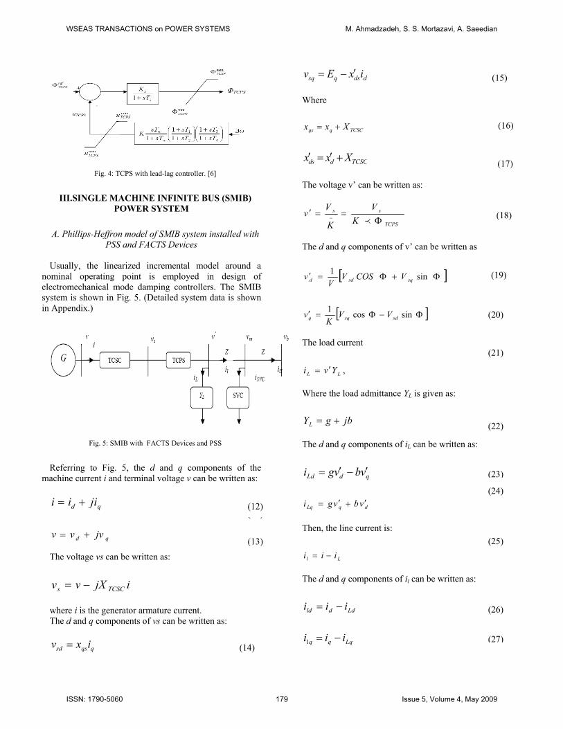
Fig. 4: TCPS with lead-lag controller. [6]
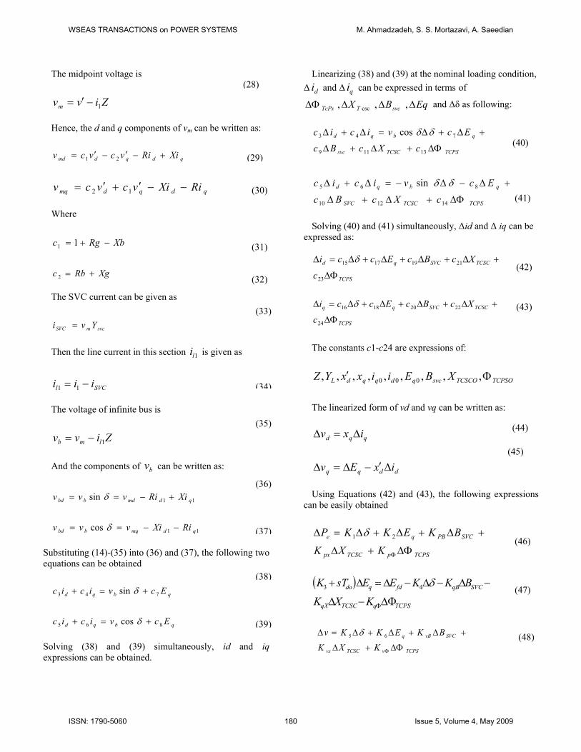
III.SINGLE MACHINE INFINITE BUS (SMIB)
POWER SYSTEM
A. Phillips-Heffron model of SMIB system installed with PSS and FACTS Devices
Usually, the linearized incremental model around a
nominal operating point is employed in design of electromechanical mode damping controllers. The SMIB system is shown in Fig. 5. (Detailed system data is shown in Appendix.)
Fig. 5: SMIB with FACTS Devices and PSS
Referring to Fig. 5, the d and q components of the
machine current i and terminal voltage v can be written as:
qd jiii +=
qd jvvv +=
The voltage vs can be written as:
ijXvv TCSCs −= where i is the generator armature current. The d and q components of vs can be written as:
qqssd ixv =
ddsqsq ixEv ′−= (15) Where
TCSCqqs Xxx += (16)
TCSCdds Xxx +′=′ (17) The voltage v’ can be written as:
TCPS
ss
KV
K
Vv
Φ==′ − p
(18)
The d and q components of v’ can be written as
[ ]Φ+Φ=′ sin1sqsdd VCOSV
Vv (19)
[ ]Φ−Φ=′ sincos1
sdsqq VVK
v (20) The load current
(21) ,LL Yvi ′=
Where the load admittance YL is given as:
jbgYL += The d and q components of iL can be written as:
(22)
qdLd vbvgi ′−′= (23)
(24) dqLq vbvgi ′+′=
(11) (12)
Then, the line current is: (25) (13)
Ll iii −= The d and q components of il can be written as:
Lddld iii −= (26)
Lqqq iii −=1 (27) (14)
WSEAS TRANSACTIONS on POWER SYSTEMS M. Ahmadzadeh, S. S. Mortazavi, A. Saeedian
ISSN: 1790-5060 179 Issue 5, Volume 4, May 2009
The midpoint voltage is
Zivvm 1−′= Hence, the d and q components of vm can be written as:
qdqdmd XiRivcvcv +−′−′= 21
qdqdmq RiXivcvcv −−′+′= 12 Where
XbRgc −+= 11
XgRbc +=2 The SVC current can be given as
svcmSVC Yvi = Then the line current in this section is given as 1li
SVCl iii −= 11 The voltage of infinite bus is
Zivv lmb 1−= And the components of can be written as: bv
11sin qdmdbbd XiRivvv +−== δ
11cos qdmqbbd RiXivvv −−== δ
Substituting (14)-(35) into (36) and (37), the following two equations can be obtained
qbqd Ecvicic 743 sin +=+ δ
qbqd Ecvicic 865 cos +=+ δ
Solving (38) and (39) simultaneously, id and iq expressions can be obtained.
Linearizing (38) and (39) at the nominal loading condition, Δ and Δ can be expressed in terms of di qi
X T EqBsvcTcPs ΔΔΔΔΦ ,,, csc and Δδ as following:
(28)
TCPSTCSCsvc
qbqd
cXcBc
Ecvicic
ΔΦ+Δ+Δ
+Δ+Δ=Δ+Δ
13119
743 cos δδ (40) (29)
TCPSTCSCSVC
qbqd
cXcBc
Ecvicic
ΔΦ+Δ+Δ
+Δ−Δ−=Δ+Δ
141210
865 sin δδ (30)
Solving (40) and (41) simultaneously, Δid and Δ iq can be
expressed as:
TCPS
TCSCSVCqd
c
XcBcEcci
ΔΦ
+Δ+Δ+Δ+Δ=Δ
23
21191715 δ
TCPS
TCSCSVCqq
cXcBcEcci
ΔΦ
+Δ+Δ+Δ+Δ=Δ
24
22201816 δ
The constants c1-c24 are expressions of:
TCPSOTCSCOsvcqdqqdL XBEiixxYZ Φ′ ,,,,,,,,, 000
The linearized form of vd and vq can be written as:
qqd ixv Δ=Δ
ddqq ixEv Δ′−Δ=Δ Using Equations (42) and (43), the following expressions
can be easily obtained
TCPSpTCSCpx
SVCPBqe
KXK
BKEKKP
ΔΦ+Δ
+Δ+Δ+Δ=Δ
Φ
21 δ
( )
TCPSqTCSCqX
SVCqBfdqdo
KXK
BKKEEsTK
ΔΦ−Δ
−Δ−Δ−Δ=Δ+
Φ
δ43
TCPSvTCSCvx
SVCvBq
KXK
BKEKKv
ΔΦ+Δ
+Δ+Δ+Δ=Δ
Φ
65 δ (48)
(41)
(31)
(42) (32)
(43) (33)
(34)
(35) (44)
(45)
(36)
(37)(46)
(38) (47)
(39)
WSEAS TRANSACTIONS on POWER SYSTEMS M. Ahmadzadeh, S. S. Mortazavi, A. Saeedian
ISSN: 1790-5060 180 Issue 5, Volume 4, May 2009
where the constants K1-K6, KpB, KpX, KpΦ, KqB, KqX, KqΦ, KvB, KvX, and KvΦ are expressions of c1-c24.
The above linearizing procedure yields the following
linearized power system model:
⎥⎥⎥⎥⎥
⎦
⎤
⎢⎢⎢⎢⎢
⎣
⎡
Δ
′ΔΔΔ
⎥⎥⎥⎥⎥⎥⎥⎥⎥⎥
⎦
⎤
⎢⎢⎢⎢⎢⎢⎢⎢⎢⎢
⎣
⎡
−−−
−−
−−
=
⎥⎥⎥⎥⎥⎥⎥
⎦
⎤
⎢⎢⎢⎢⎢⎢⎢
⎣
⎡
ΔΕ
ΔΕ
Δ
Δ
•
•
•
•
fd
q
AA
A
A
A
dododo
fd
qE
E
TTKK
TKK
TTK
TK
MK
MD
Mk
ωδ
ω
δ
10
10
01
003770
65
34
2
⎥⎥⎥⎥⎥
⎦
⎤
⎢⎢⎢⎢⎢
⎣
⎡
ΔΦΔΔ
⎥⎥⎥⎥⎥⎥⎥⎥⎥
⎦
⎤
⎢⎢⎢⎢⎢⎢⎢⎢⎢
⎣
⎡
−−−
−−−
−−−
+
Φ
Φ
Φ
TCPS
TCSC
SVC
pss
A
vA
A
vXA
A
vBA
A
A
do
q
do
qX
do
qB
PPXPB
XB
u
TKK
TKK
TKK
TK
TK
TK
TK
MK
MK
MK
0
0
0000
IV. Objective Function
The state-space equation of a power system installed
with PSSs and FACTS devices, linearized about a selected operating point, can be compactly written as following:
PΔx=AΔx+BΔu Where x is state vector; u is the vector of input reference
signals; and A is the state matrix which is the function of controller parameters.
The dynamic characteristics of the system are influenced by the locations of eigenvalues of matrix A. Hence, in order to have a good dynamic characteristic (i.e. good damping), it is necessary to shift eigenvalues associated with poorly-damped modes to positions in the complex plane with good damping characteristics. This is called as tuning.
The objective of the tuning problem is to find a set of appropriate controller parameters to improve the system damping. However, the objective function used to be maximized with respect to controller parameters in the single and coordinated control design is:
f(K,λ1, λ2,....., λm, , z1, z2 ,,..., ,zm)= ∑ (51) ( )( 2Re il λ )
where: K= controller parameters to be optimized λi = the ith eigenvalue to be placed zi = the eigenvector associated with the ith eigenvalue;
m = number of selected eigenvalues The related eigenvalues and eigenvectors are nonlinear
functions of parameter vector K. The maximization of the objective function is subject to equality constraints formed from the eigenvalue-eigenvector equations and inequality constraints which represent the bounds required on the selected eigenvalues and controller parameters. V. Optimization Problem Formulation
In this study, the proposed objective function is optimized
individually. The problem constraints are the stabilizer optimized parameter bounds. Therefore, the design problem can be formulated as the following optimization problem.
Maximize f (49) Subject to
Ki min ≤Ki≤ Ki max T1i min ≤T1i ≤T1i max
T2i min ≤ T2i ≤ T2i max T3i min ≤ T3i ≤ T3i max T4i min ≤ T4i ≤ T4i max
Genetic algorithm (GA) is employed to solve this
optimization problem. Searching is done for optimal set of the stabilizer parameters, i.e. Ki, T1i, T2i, T3i, T4i where i is the Number of stabilizers considered. VI. Stabilizer Tuning and Simulation Results
To study the effectiveness of the proposed controllers, three different loading conditions are considered for eigenvalue analysis. These conditions are as following:
(50)
1. Light loading (Pe, Qe) = (0.25, 0.02) p.u. 2. Normal loading (Pe, Qe) = (1.0, 0.02) pu. 3. Heavy loading (Pe, Qe) = (1.5, 0.45) pu.
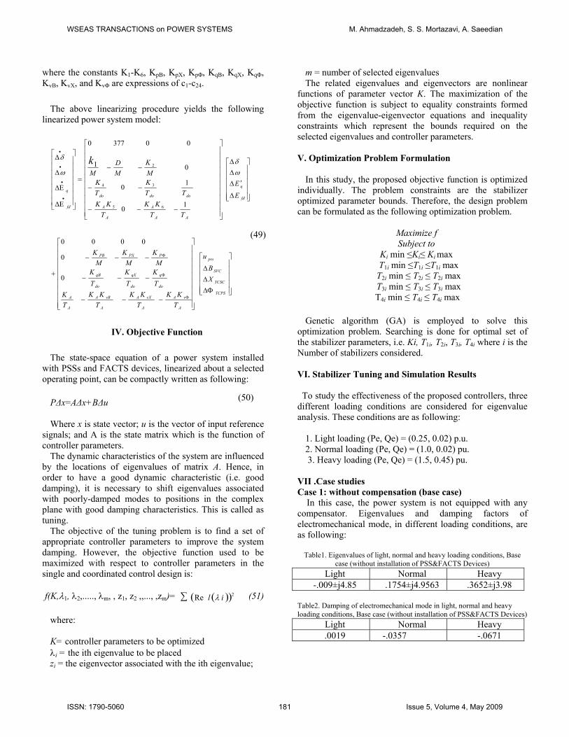
VII .Case studies Case 1: without compensation (base case) In this case, the power system is not equipped with any compensator. Eigenvalues and damping factors of electromechanical mode, in different loading conditions, are as following:
Table1. Eigenvalues of light, normal and heavy loading conditions, Base case (without installation of PSS&FACTS Devices)
Light Normal Heavy -.009±j4.85 .1754±j4.9563 .3652±j3.98
Table2. Damping of electromechanical mode in light, normal and heavy loading conditions, Base case (without installation of PSS&FACTS Devices)
Light Normal Heavy .0019 -.0357 -.0671
WSEAS TRANSACTIONS on POWER SYSTEMS M. Ahmadzadeh, S. S. Mortazavi, A. Saeedian
ISSN: 1790-5060 181 Issue 5, Volume 4, May 2009
Simulated results in this case are shown in figs. 6-8. These figures shown Step response of deviation of generator speed in normal, light and heavy loading conditions, without compensation,
Fig 6: Step response of deviation of generator speed in light loading
condition, without compensation
Fig 7: Step response of deviation of generator speed in heavy loading
condition, without compensation
Fig 8: Step response of deviation of generator speed in normal loading
condition, without compensation
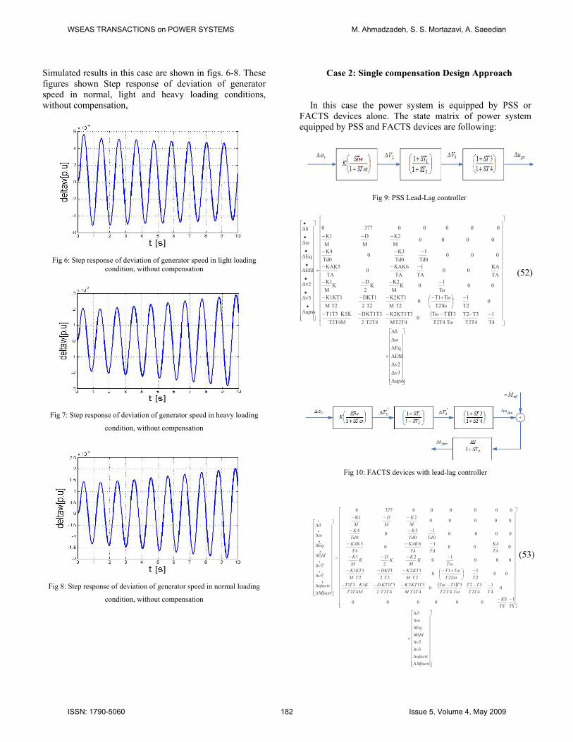
Case 2: Single compensation Design Approach
In this case the power system is equipped by PSS or FACTS devices alone. The state matrix of power system equipped by PSS and FACTS devices are following:
Fig 9: PSS Lead-Lag controller
( )
⎥⎥⎥⎥⎥⎥⎥⎥⎥
⎦
⎤
⎢⎢⎢⎢⎢⎢⎢⎢⎢
⎣
⎡
×
⎥⎥⎥⎥⎥⎥⎥⎥⎥⎥⎥⎥⎥⎥⎥⎥⎥⎥⎥
⎦
⎤
⎢⎢⎢⎢⎢⎢⎢⎢⎢⎢⎢⎢⎢⎢⎢⎢⎢⎢⎢
⎣
⎡
−−−−−−
−⎟⎠
⎞⎜⎝
⎛ +−−−−
−−−−
−−−
−−−
−−−
=
⎥⎥⎥⎥⎥⎥⎥⎥⎥⎥⎥⎥⎥⎥⎥⎥⎥⎥
⎦
⎤
⎢⎢⎢⎢⎢⎢⎢⎢⎢⎢⎢⎢⎢⎢⎢⎢⎢⎢
⎣
⎡
•
•
•
•
•
•
•
ΔupssΔv3Δv2ΔΕfdΔΕqΔωΔδ
T41
T2T4T3T2
TωT4T2T3T1Tω
0T2T4M
K2KT1T3T2T42KT1T3D
T2T4MK1KT1T3
0T2
1T2Tω
TωT10
T2MK2KT1
T22DKT1
T2MK1KT1
00 Tω
10K
MK2
K2D
KMK1
TAKA
0 0TA
1TAKAK6
0TAKAK5
00 0Td0
1Td0
K30
Td0K4
00 00MK2
MD
MΚ1
0 0 00 0377 0
Δupss
Δv3
Δv2
ΔΕfd
ΔΕq
Δω
Δδ
(52)
Fig 10: FACTS devices with lead-lag controller
( )
⎥⎥⎥⎥⎥⎥⎥⎥⎥⎥⎥
⎦
⎤
⎢⎢⎢⎢⎢⎢⎢⎢⎢⎢⎢
⎣
⎡
ΔΔΔΔΔΕΔΕΔΔ
×
⎥⎥⎥⎥⎥⎥⎥⎥⎥⎥⎥⎥⎥⎥⎥⎥⎥⎥⎥⎥
⎦
⎤
⎢⎢⎢⎢⎢⎢⎢⎢⎢⎢⎢⎢⎢⎢⎢⎢⎢⎢⎢⎢
⎣
⎡
−−
−−−−−−
−⎟⎠⎞
⎜⎝⎛ +−−−−
−−−−
−−−
−−−
−−Κ−
=
⎥⎥⎥⎥⎥⎥⎥⎥⎥⎥⎥⎥⎥⎥⎥
⎦
⎤
⎢⎢⎢⎢⎢⎢⎢⎢⎢⎢⎢⎢⎢⎢⎢
⎣
⎡
ΔΔ
′Δ
′Δ
ΔΕ
ΔΕ
Δ
Δ
•
•
•
•
•
•
•
Mfactsufactsvv
fdq
TSTSKS
TTTTT
TTTTTT
TTMTKTK
TTTKTD
MTTKKTT
TTTTT
TMKTK
TDKT
TMKTK
TK
MKKDK
MK
TAKA
TATAKAK
TAKAK
TdTdK
TdK
MK
MD
M
Mfactsufacts
v
v
fd
q
32
100 000 0
041
4232
42310
42312
42231
42131
0 0 21
210
212
221
211
00 01022
1
0 001605
00 0001
030
04
00 0002100 00003770
3
2
ωδ
ωω
ωω
ω
ω
δ
(53)
WSEAS TRANSACTIONS on POWER SYSTEMS M. Ahmadzadeh, S. S. Mortazavi, A. Saeedian
ISSN: 1790-5060 182 Issue 5, Volume 4, May 2009
Equations (52) and (53) show the linearized power system model equipped by PSS and FACTS devices respectively. GA has been applied to optimize the settings of the proposed stabilizers. The final settings of the optimized parameters, eigenvalues and damping factors of electromechanical mode for the proposed stabilizers in light loading condition are given in Tables 3-5:
Table3. Optimum parameters of Stabilizer in light loading condition, single design (with installation of PSS or FACTS Devices)
Optimum parameter
PSS TCSC TCPS SVC
T1 .1178 .0476 .0576 1 T2 .1000 .1000 .1000 .3100 T3 .1645 .0398 .0317 .0120 T4 .1000 .1000 .1000 .3000 K 19.2467 95.7300 90.870 89.94
Table4. System eigenvalues in light loading condition, Single design
(with installation of PSS or FACTS Devices) PSS TCSC TCPS SVC
-.87±j5.06 -6.98±j5.5
-16.77 -7.7 -.2
-.82±j5.1 -9.9±j3.8
-19.53 -10.72 -8.43 -.203
-4.5±j6.6 -9.3±j3.4
-17.37 -10.76 -4.33 -.212
-.68±j4.7 -7.04±j2.08 -19.9 -9.93 -2.55 -.199
Table5. Damping of system electromechanical mode in light loading condition, single design (with installation of PSS or FACTS Devices)
PSS TCSC TCPS SVC .2548 .2631 .5802 .1516
Simulated results in this case are shown in figs. 11-12. These figures show effect of PSSs and FACTS devices on Step response of deviation of generator speed and step response of generator power angle in light loading condition.
Fig11:step response generator power angle in light loading condition,
single design
Fig12: step response deviation of generator speed in light loading condition,
single design
The final settings of the optimized parameters, eigenvalues
and damping factors of electromechanical mode for the
proposed stabilizers in normal loading condition are given in
Tables 6-8:
Table6. Optimal parameters of Stabilizer in normal loading condition, single design
Optimal Parameter PSS TCSC TCPS SVC
T1 .1478 .0751 .0790 1 T2 .1000 .1000 .1000 .3000 T3 .1741 .0765 .0754 .0110 T4 .1000 .1000 .1000 .3000 K 21.2467 98.000 100.000 93.9870
Table7. System eigenvalues in normal loading condition, Single design
(with installation of PSS or FACTS Devices) PSS TCSC TCPS SVC
-3.24±j5.6 -3.39±j5.9 -19.497 -7.414 -.2055
-3.5±j4.1 -5.7±j6.7 -11.4±j1.2
-18.67 -.2
-3.1±j3.5 -7.1±j7.9 -11.04±j.83
-10.76 -17.8
-.2099
-2.26±j4.6 -2.49±j5.07 -20.45 -14.26 -2.63 -.2
Table8. Damping of electromechanical mode in normal loading condition
(with installation of PSS or FACTS Devices) PSS TCSC TCPS SVC
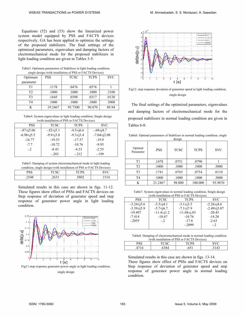
.4716 .6384 .651 .3143 Simulated results in this case are shown in figs. 13-14. These figures show effect of PSSs and FACTS devices on Step response of deviation of generator speed and step response of generator power angle in normal loading condition.
WSEAS TRANSACTIONS on POWER SYSTEMS M. Ahmadzadeh, S. S. Mortazavi, A. Saeedian
ISSN: 1790-5060 183 Issue 5, Volume 4, May 2009
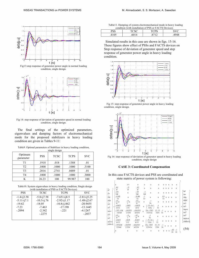
Fig13:step response of generator power angle in normal loading
condition, single design.
Fig 14: step response of deviation of generator speed in normal loading
condition, single design. The final settings of the optimized parameters,
eigenvalues and damping factors of electromechanical mode for the proposed stabilizers in heavy loading condition are given in Tables 9-11:
Table9. Optimal parameters of Stabilizer in heavy loading condition,
single design
Optimum .parameter PSS TCSC TCPS SVC
T1 .1918 .018 .1388 .01 T2 .1000 .1000 .1000 .3100 T3 .2016 .2741 .0489 .01 T4 .1000 .1000 .1000 .3000 K 26.23 100 99.987 100
Table10. System eigenvalues in heavy loading condition, Single design
(with installation of PSS or FACTS Devices) PSS TCSC TCPS SVC
-1.4±j3.58 -5.11±j7.1 -19.62 -7.23 -.2094
-5.8±j7.58 -10.3±j.76 -18.05
-7.463 -2.342 -.2275
-7.651±j8.5 -2.92±j1.17 -10.8±j.862
-17.198 -.221
-2.81±j5.25 -1.48±j2.67 -20.9455 -13.1445 -4.1267 -.2037
Table11. Damping of system electromechanical mode in heavy loading condition (with installation of PSS or FACTS Devices)
PSS TCSC TCPS SVC .4105 .6014 .8712 .4948
Simulated results in this case are shown in figs. 15-16. These figures show effect of PSSs and FACTS devices on Step response of deviation of generator speed and step response of generator power angle in heavy loading condition.
Fig 15: step response of generator power angle in heavy loading condition, single design.
Fig 16: step response of deviation of generator speed in heavy loading
condition, single design
CASE 3: Coordinated Compensation
In this case FACTS devices and PSS are coordinated and state matrix of power system is following:
( )
( )
⎥⎥⎥⎥⎥⎥⎥⎥⎥⎥⎥⎥⎥⎥⎥⎥⎥⎥⎥⎥⎥⎥⎥⎥⎥⎥⎥⎥⎥⎥⎥
⎦
⎤
⎢⎢⎢⎢⎢⎢⎢⎢⎢⎢⎢⎢⎢⎢⎢⎢⎢⎢⎢⎢⎢⎢⎢⎢⎢⎢⎢⎢⎢⎢⎢
⎣
⎡
−−
−−−−−−
−⎟⎠⎞
⎜⎝⎛ +−−−−
−−−−
−−−−−−
−⎟⎠⎞
⎜⎝⎛ +−−−−
−−−−
−−−
−−−
−−Κ−
=
⎥⎥⎥⎥⎥⎥⎥⎥⎥⎥⎥⎥⎥⎥⎥⎥⎥⎥⎥⎥⎥
⎦
⎤
⎢⎢⎢⎢⎢⎢⎢⎢⎢⎢⎢⎢⎢⎢⎢⎢⎢⎢⎢⎢⎢
⎣
⎡
ΔΔ
′Δ
′Δ
Δ
Δ
Δ
ΔΕ
ΔΕ
Δ
Δ
•
•
•
•
•
•
•
•
•
•
TSTSKS
TTTTT
TTTTTT
TTMTKTK
TTTKTD
MTTKKTT
TTTTT
TMKTK
TDKT
TMKTK
TK
MKKDK
MK
TTTTT
TTTTTT
TTMTKTK
TTTKTD
MTTKKTT
TTTTT
TMKTK
TDKT
TMKTK
TK
MKKDK
MK
TAKA
TATAKAK
TAKAK
TdTdK
TdK
MK
MD
M
Mfactsufacts
v
v
upss
v
v
fd
q
1000000000
000041
4232
42310
42312
42231
42131
0000021
210
212
221
211
0000001022
1
000041
4232
42310
42312
42231
42131
0000021
210
212
221
211
0000001022
1
0000001605
000000001
030
04
00000000210000000003770
3
2
3
2
ωω
ωω
ω
ωω
ωω
ω
ω
δ
⎥⎥⎥⎥⎥⎥⎥⎥⎥⎥⎥⎥⎥⎥⎥
⎦
⎤
⎢⎢⎢⎢⎢⎢⎢⎢⎢⎢⎢⎢⎢⎢⎢
⎣
⎡
ΔΔ
′Δ
′ΔΔΔΔΔΕΔΕΔΔ
×
Mfactsufactsvvupssvv
fdq
32
32
ωδ
(54)
WSEAS TRANSACTIONS on POWER SYSTEMS M. Ahmadzadeh, S. S. Mortazavi, A. Saeedian
ISSN: 1790-5060 184 Issue 5, Volume 4, May 2009
A. Coordinated Design [PSS & SVC] According to tables.7,9 and 11, because that Damping of
system electromechanical mode equipped by SVC and PSS at all loading conditions is smaller than another devices .Therefore, In this stage the coordinated design of PSS and SVC-based stabilizer is done at whole of loding conditions.
Table15. Damping of system electromechanical mode in all of loading conditions, single and coordinated design
single design coordinated design
Loading PSS SVC PSS&SVC
Light .2548 .1516 .2685
Normal .4716 .3143 .6984 Heavy .3141 .4948 .6821
Both stabilizers PSS & SVC are simultaneously tuned by PSO search for the optimum controllers parameter settings.
System eigenvalues for different loading conditions in this case are following:
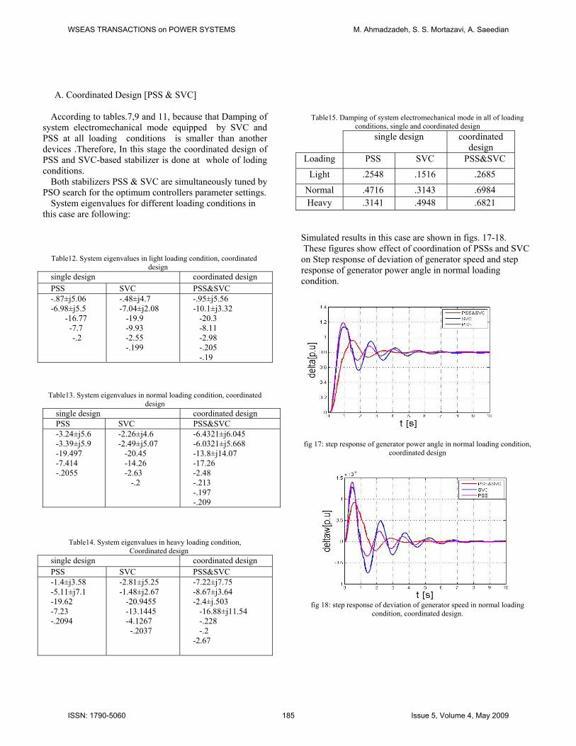
Simulated results in this case are shown in figs. 17-18.
These figures show effect of coordination of PSSs and SVC on Step response of deviation of generator speed and step response of generator power angle in normal loading condition.
Table12. System eigenvalues in light loading condition, coordinated
design single design coordinated design PSS SVC PSS&SVC -.87±j5.06 -6.98±j5.5
-16.77 -7.7 -.2
-.48±j4.7 -7.04±j2.08 -19.9 -9.93 -2.55 -.199
-.95±j5.56 -10.1±j3.32 -20.3 -8.11 -2.98 -.205 -.19
Table13. System eigenvalues in normal loading condition, coordinated design
single design coordinated design PSS SVC PSS&SVC -3.24±j5.6 -3.39±j5.9 -19.497 -7.414 -.2055
-2.26±j4.6 -2.49±j5.07 -20.45 -14.26 -2.63 -.2
-6.4321±j6.045 -6.0321±j5.668 -13.8±j14.07 -17.26 -2.48 -.213 -.197 -.209
fig 17: step response of generator power angle in normal loading condition,
coordinated design
Table14. System eigenvalues in heavy loading condition,
Coordinated design single design coordinated design PSS SVC PSS&SVC -1.4±j3.58 -5.11±j7.1 -19.62 -7.23 -.2094
-2.81±j5.25 -1.48±j2.67 -20.9455 -13.1445 -4.1267 -.2037
-7.22±j7.75 -8.67±j3.64 -2.4±j.503 -16.88±j11.54 -.228 -.2 -2.67
fig 18: step response of deviation of generator speed in normal loading condition, coordinated design.
WSEAS TRANSACTIONS on POWER SYSTEMS M. Ahmadzadeh, S. S. Mortazavi, A. Saeedian
ISSN: 1790-5060 185 Issue 5, Volume 4, May 2009
B. Coordinated Design [PSS & TCSC]
According to tables 1 because that Damping of system
electromechanical mode in coordinated design of PSS with SVC-based stabilizer at light loading conditions is smaller than another condition. Therefore, in this stage the coordinated design of PSS and TCSC-based stabilizer is done at this loading condition. Eigenvalues and damping of electromechanical mode are in tables 17 and 18 respectively.
Table16. System eigenvalues in light loading condition, coordinated design
single design coordinated design PSS TCSC PSS&TCSC -.87±j5.06 -6.98±j5.5 -16.77 -7.7 -.2
-.82±j5.1 -9.9±j3.8 -19.53 -10.72 -8.43 -.203
-1.53±j5.26 -7.33±j3.54 -16.22±j2.6 -10 -.205 -.2
Table17. Damping of system electromechanical mode in light loading condition, single and coordinated design
single design coordinated design PSS TCSC PSS&TCSC .2548 .2631 .4203
Table18. Controller optimal parameters in light loading condition for single and coordinated design.
Controller optimal
parameter
single design
coordinated design
PSS TCSC PSS TCSC T1 .178 .0476 .305 .2053 T2 .09 .1 .11 .1 T3 .645 .0398 .4085 .1624 T4 .1 .108 .1 .1 K 19.546 95.73 30.6035 55.137
Table19. Damping of system electromechanical mode in light loading
condition, single and coordinated designs single design
coordinated design
PSS TCSC PSS&TCSC .2548 .2631 .4203
Table20. System eigenvalues in light loading condition,single and
coordinated designs. Sd
cingle esign
oordinated design
PSS T PCSC SS&TCSC --
---
--
----
----
---
.87±j5.06 6.98±j5.5
16.77 7.7 .2
.82±j5.1 9.9±j3.8
19.53 10.72 8.43 .203
1.53±j5.26 7.33±j3.54 14.22±j2.6 10±j5.65
5.86 .205 .2
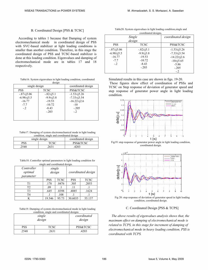
Simulated results in this case are shown in figs. 19-20. These figures show effect of coordination of PSSs and TCSC on Step response of deviation of generator speed and step response of generator power angle in light loading condition.
Fig19: step response of generator power angle in light loading condition,
coordinated design.
Fig 20: step response of deviation of generator speed in light loading
condition, coordinated design.
C. Coordinated Design [PSS & TCPS]
The above results of eigenvalues analysis shows that, the maximum effect on damping of electromechanical mode is related to TCPS, in this stage for increment of damping of electromechanical mode in heavy loading condition, PSS is coordinated with TCPS.
WSEAS TRANSACTIONS on POWER SYSTEMS M. Ahmadzadeh, S. S. Mortazavi, A. Saeedian
ISSN: 1790-5060 186 Issue 5, Volume 4, May 2009
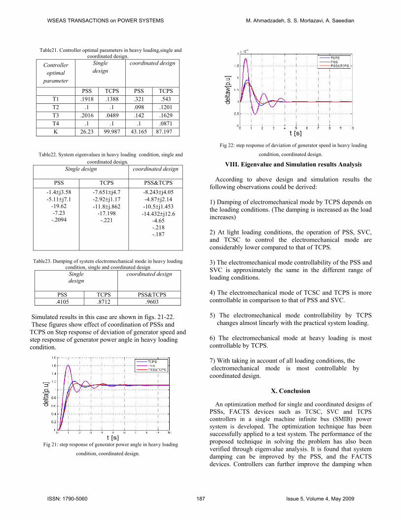
Table21. Controller optimal parameters in heavy loading,single and coordinated design.
Controller optimal
parameter
Single design
coordinated design
PSS TCPS PSS TCPS T1 .1918 .1388 .321 .543 T2 .1 .1 .098 .1201 T3 .2016 .0489 .142 .1629 T4 .1 .1 .1 .0871 K 26.23 99.987 43.165 87.197
Table22. System eigenvalues in heavy loading condition, single and coordinated design.
Single design
coordinated design
PSS TCPS PSS&TCPS -1.4±j3.58 -5.11±j7.1
-19.62 -7.23 -.2094
-7.651±j4.7 -2.92±j1.17 -11.8±j.862
-17.198 -.221
-8.243±j4.05 -4.87±j2.14 -10.5±j1.453
-14.432±j12.6 -4.65 -.218 -.187
Table23. Damping of system electromechanical mode in heavy loading
condition, single and coordinated design Single design
coordinated design
PSS TCPS PSS&TCPS .4105 .8712 .9603
Simulated results in this case are shown in figs. 21-22. These figures show effect of coordination of PSSs and TCPS on Step response of deviation of generator speed and step response of generator power angle in heavy loading condition.
Fig 21: step response of generator power angle in heavy loading
condition, coordinated design.
Fig 22: step response of deviation of generator speed in heavy loading
condition, coordinated design.
VIII. Eigenvalue and Simulation results Analysis According to above design and simulation results the
following observations could be derived:
1) Damping of electromechanical mode by TCPS depends on the loading conditions. (The damping is increased as the load increases)
2) At light loading conditions, the operation of PSS, SVC, and TCSC to control the electromechanical mode are considerably lower compared to that of TCPS. 3) The electromechanical mode controllability of the PSS and SVC is approximately the same in the different range of loading conditions.
4) The electromechanical mode of TCSC and TCPS is more controllable in comparison to that of PSS and SVC.
5) The electromechanical mode controllability by TCPS changes almost linearly with the practical system loading.
6) The electromechanical mode at heavy loading is most controllable by TCPS.
7) With taking in account of all loading conditions, the electromechanical mode is most controllable by coordinated design.
Х. Conclusion
An optimization method for single and coordinated designs of
PSSs, FACTS devices such as TCSC, SVC and TCPS controllers in a single machine infinite bus (SMIB) power system is developed. The optimization technique has been successfully applied to a test system. The performance of the proposed technique in solving the problem has also been verified through eigenvalue analysis. It is found that system damping can be improved by the PSS, and the FACTS devices. Controllers can further improve the damping when
WSEAS TRANSACTIONS on POWER SYSTEMS M. Ahmadzadeh, S. S. Mortazavi, A. Saeedian
ISSN: 1790-5060 187 Issue 5, Volume 4, May 2009
the controllers’ parameters are properly tuned coordinately. These results show the importance of the control coordination of PSS and FACTS controllers and the effectiveness of the proposed technique.
In this paper a SMIB power system has been simulation study. It is proposed to apply the proposed method to a large multi-machine system for more investigation.
ХI. References
[1] F. deMello and C. Concordia, “Concepts of Synchronous Machine Stability as Affected by Excitation Control,” IEEE Trans. PAS, Vol. 88, pp. 316-329, 1969. [2] P. Pourbeik and M.J. Gibbard,”Simultaneous coordination of power system stabilizers and FACTS device stabilizers in a multimachine power system for enhancing dynamic performance,” IEEE Trans. Power Systems,vol. 13, no. 2, pp. 786-792, May 1998. [3] K. Sebaa, M. Boudour, “Multi-Objective GeneticAlgorithms for power system planning,”Accepted forArab countries CIGRE Conference, Amman, Sept. 2007. [4] S. Panda and N. Prasad Padhy, “Power system with PSSs and FACTS Controller: Modelling, Simulation and Simultaneous Tuning Employing Genetic Algorithm,” International Journal of Electrical,Computer and Systems Engineering, Vol.1, No. 1, pp.9-18, 2007. [5] P. Kunder, “Power System Stability and Control”, Electric Power Research Institute/ MagGrow-Hill, 1994 [6]S. M. Bamasak and M. A Abido, “Assessment Study Of Shunt Facts-Based Controllers Effectiveness On Power System Stability Enhancement,” 39th UPEC Proceedings, Vol. 1, pp 65-71, Sept 2004. [7] A. Griffo, D. Lauria,˝Some Considerations on Power System
Stability Improvement by FACTS Devices,˝ SPEEDAM 2006 [8] E. Acha, C. R. Fuerte-Esquivel, H. Ambriz-Pérez, C.Angeles Camacho: FACTS: Modelling and simulation in power networks, Chichester (U.K.) - Wiley, 2004. [9]N.Mithulananthan,C.A. Canizares, J. Reeve, and G.J.Rogers,”Comparison of PSS, SVC, and STATCOM controllers for damping power system oscillations,” IEEE Trans. Power Systems, vol.18,no. 2, pp. 786-792, May 2003 [10]P.X.Zhang, Q.Y. Jiang, and Y.J. Cao. Design of tcsc nonlinear controller based on multi-objective genetic algorithm. Automation of Electric Power Systems, 27(13):40–44, 2003. [11] M.A. Abido. Environmental/economic power dispatch using multiobjective evolutionary algorithms. IEEE Transactions on Power Systems, 18(4):1529–1537, 2003. [12] M. Noroozian, M. Ghandhari, G. Andersson, J. Gronquist, and I.Hiskens,”A robust control strategy for shunt and series reactivecompensators to damp electromechanical oscillations,” IEEETrans. Power Delivery, vol. 16, no. 4, pp. 812-817, October 2001. [13] H.F. Wang,”Phillips-Heffron model of power systems installed with
STATCOM and applications,” IEE Proc.-Gener. Transm. Distrib., vol. 146, no. 5, pp. 521-527, September 1999.
[14] CIGRE TF 38.01.08: ”Modeling of power electronics equipment (FACTS) in load flow and stability programs: a representation guide for powersystem planning and analysis”, 1998. [15] E.Z. Zhou,”Application of static var compensators to increase power system damping,” IEEE Trans. Power Systems, vol. 8, no. 2, pp. 786-792, May 1993. [16] S. M. Bamasak and M. A Abido, “Assessment Study Of Shunt Facts-Based Controllers Effectiveness On Power System Stability Enhancement,” 39th UPEC Proceedings, Vol. 1, pp 65-71, Sept 2004.
WSEAS TRANSACTIONS on POWER SYSTEMS M. Ahmadzadeh, S. S. Mortazavi, A. Saeedian
ISSN: 1790-5060 188 Issue 5, Volume 4, May 2009