a novel control scheme for pitch regulated vertical axis wind
TRANSCRIPT

A Novel Control Scheme for Pitch Regulated Vertical Axis Wind Turbine
Amr Abdel Kader Professor, Mechanical Engineering Department
The British University in Egypt Cairo, Egypt
Amir Abdelmawla Research Assistant, Center for Advanced Materials
The British University in Egypt Cairo, Egypt
Abstract— In this paper a small 5 kW rated power Vertical Axis Wind Turbine (VAWT) equipped with a novel design for pitch control and actuation system was introduced. This novel design allows the pitch control system to rely on wind speed measurement only and to perform independently from the blades azimuthal position. A combined feedback – feed forward controller, for pitch control of this VAWT was synthesized. The variation of wind speed as well as other main operating performance parameters of the VAWT necessitates the derivation of multi linear models for rotor dynamics in the neighborhood of nominal operating conditions. These linear models were derived from the torque-angular speed characteristics of the VAWT and result in several first order transfer functions. These transfer functions express rotor speed with respect to both blade pitch angle and wind speed (ω/θ & ω/Vw). Gains and time constants of these transfer functions were determined in terms of rotor moment of inertia, rotor aerodynamic characteristics and generator torque characteristics. The control loop of the DC servo motor that actuates the pitch angle was incorporated in the control scheme. The Internal Model Control (IMC) method was adopted to synthesize PID controllers for the DC servo motor as well as the VAWT’s angular speed rotor. The associated proportional gains, integral and derivative time constants were determined for set point tracking conditions. To improve load rejection performance of VAWT’s angular speed rotor controller a feed-forward controller is added to compensate for wind speed fluctuations.
The above synthesized control scheme was adopted for controlling the pitch angle of the VAWT such that the rotor’s angular speed is kept at its rated value. Simulation results at different nominal wind speeds over the rated value have shown considerably improved load rejection characteristics of the combined PID feed forward control scheme.
Keywords—Vertical Axis Wind Turbine; Double Actuator Disc model; PID; Feed forward.
I. INTRODUCTION The main objectives of individual pitch control of Vertical
Axis Wind Turbines (VAWT) are to provide high starting torque at cut in wind speed, maximize generated power at low wind speeds and regulate power at its rated value at high wind speeds. Additional objective is to limit dynamic loads acting on the VAWT. Several challenges are encountered with the
implementation of individual pitch control of straight bladed VAWT. The necessity to correlate the azimuthal position of each blade to wind speed direction and the required speed of response of individual blade pitch actuation systems are the main challenges that add to both complexity and cost of the VAWT.
This paper presents a combined feedback feed forward controller for pitch control at high wind speeds for 5 kW power straight bladed VAWT. This VAWT has a novel design for pitch control and actuation system. In this design the blade is split into two identical segments. Upper and lower sets of blades are equipped with a single actuation system. Fig. 1 presents a 3-Dimensional illustration of the design.
International Scientific Journal Environmental Science http://environment.scientific-journal.com

Fig. 1. VAWT CAD model
Table 1 presents the main technical specifications of the VAWT.
TABLE I. MAIN TECHNICAL SPECIFICATIONS OF VAWT
Parameter Value
Rated power (kW) 5
Cut in wind speed (m/s) 3
Rated wind speed (m/s) 8
Cut out wind speed (m/s) 20
Rated angular speed (rad/s) 10.8
Number of blades 6
Rotor diameter (m) 4.7
Blade length (m) 3
Blade width (m) 0.47
Tip Speed Ratio 3.2
In this work we consider the case in which the upper set is actuated with a negative pitch angle while the lower set is actuated with a pitch angle of same magnitude and opposite sense. This novel design allows the pitch control system to rely on wind speed measurement only and to perform independently from the blades azimuthal position. The paper
comprises six sections. In section II the aerodynamic model of the VAWT is introduced. In section III a model for VAWT’s rotor dynamics is developed. Section IV is dedicated for synthesizing the control scheme. In section V, the computation algorithm as well as simulation results and discussion are introduced.
II. AERODYNAMIC MODELING In order to model the performance of a vertical-axis wind
turbine, the Double-Multiple Stream Tube (DMST) with variable interference factor is adopted. The DMST model is based on the conservation of momentum principle and derived from the actuator disc theory. It has been used successfully to predict overall torque and thrust loads on Darrius rotors [1]. The main advantage of DMST model is its limited computation time while its main disadvantage is that it doesn't take dynamic stall effects into consideration [2]. The DMST model is an extension of the multiple stream tube models. It divides the flow pattern of the VAWT into upstream and downstream zones [3]. The incoming wind in the downstream zone is assumed to be the upstream wake velocity. This provides a better account for the wake effects as shown in Fig. 2.
The swept volume of the VAWT’s rotor is divided into adjacent, aerodynamically independent stream tubes. Each stream tube is identified by its middle angle, Δφ as shown in Fig. 2. The analysis of the flow conditions is conducted on each stream tube using a combination of the momentum and blade element theorems. Induction factors a, a' for both up and down stream regions are introduced [1,3], these factors will account for the deceleration of wind speed near the rotor. If the front and rear segments of the VAWT’s rotor are represented by two disks in series, wind speed will be decelerated twice for upstream and downstream flow zones respectively. Equations (1), (2) and (3) determine upstream as well as downstream wind speeds in terms of induction factors a and a'.
Vu = (1- a)V∞ (1)
Ve = (1- 2a)V∞ (2)
Vd = (1- 2a)(1- a')V∞ (3) Fig. 3 shows the blade velocity triangle at an azimuthal
position defined by angle φ. The angle of attack (AOA) can be determined from (4):
α = γ - θ (4)
International Scientific Journal Environmental Science http://environment.scientific-journal.com

Stre
am T
ube
Blade(Disc)
ϕΔ
ϕ
∞V
Vu
Vd
Ve
Vo
Upstream
Downstream
Equilibrium Zone
Fig. 2. Double Multiple Stream Tube model (DMST) for VAWT
Equations (5), (6) and (7) determine tangential force
coefficient, normal force coefficient and the axial thrust force coefficient. Lift and drag coefficients data for the blade airfoil section is used to calculate the axial thrust force coefficient.
CT = -CL sin γ – CD cos γ (5)
CN = -CL cos γ + CD sin γ (6)
CY = -CT sin φ – CN cos φ (7)
Fig. 3. Blade velocity triangle
Equation (8) determines the stream-wise force at the actuator disk that results from conservation of momentum.
Cm = 4a(1 – a) (8)
Using an initial guess of the upstream induction factor, an iterative process is adopted that simultaneously solves (7) and (8). These equations are solved for each stream tube position twice, for the upwind flow region as well as for the downwind flow region [3]. Once an acceptable convergence is obtained, tangential, normal forces and turbine‘s torque angular speed characteristics are computed, form (5), (6), and (9).
T = 0.5ρVr 2 CRLCT (9)
Two groups of torque characteristics are developed. Fig. 4 presents the torque characteristics at different Wind speeds over the rated value and at constant Pitch angle. Fig. 5 presents the torque characteristics at a constant wind speed and different pitch angles.
Fig. 4. Torque characteristics at constant pitch angle
Fig. 5. Torque characteristics at constant wind speed
III. DYNAMIC MODEL OF THE VAWT Simple linear models for the VAWT dynamics are derived
in the neighborhood of nominal operating conditions. The variation of wind speed as well as other main operating performance parameters of the VAWT necessitates the
International Scientific Journal Environmental Science http://environment.scientific-journal.com
derivation of multi linear models. Each model will describe the dynamic behavior of the VAWT in the neighborhood of a single nominal operating point. These linear models result in several first order transfer functions that express rotor speed with respect to both effective blade pitch angle and wind speed. Gains and time constants of these transfer functions are expressed in terms of rotor moment of inertia, rotor aerodynamic characteristics and generator torque characteristics.
A single – mass linearized model of the VAWT in the neighborhood of an operating point (Ωo, ϴo and Vo) is given by:
JTωo = [MTω] ω+[MT θ] θ+[ MTVw] VW - [MLω] ω (10)
Where:
• Ωo is the rated generator speed • ϴo is the operating blade pitch angle • Vo is the operating wind speed
• MTω = ∂MT/∂ω at Vo, θo • MTθ = ∂MT/∂θ at Vo, Ωo • MTVw = ∂MT/∂Vw at θo, Ωo
• MLω = ∂ML/∂ω In the above model stiffness and damping effects of the
turbine drive train are neglected .The transfer functions ω(s)/θ(s) and ω(s)/Vw(s) are derived from the above introduced model such that:
ω(s)/θ(s) = G1/(TC1S+1) (11) ω(s)/Vw(s) = G2/(TC1S+1) (12)
Where the gains G1, G2 and the time constant TC1are given
by:
G1 = MTθ/(MLω – MTω) (13) G2 = MTV/(MLω – MTω) (14) TC1 = JT/(MLω – MTω) (15)
Values of G1, G2 and TC1 are computed by evaluating the
partial derivatives of the torque characteristics at constant pitch angle and at constant wind speed.
IV. CONTROLLERS SYNTHESIS Fig. 6 presents the block diagram of the control system
that comprises two cascaded control loops. The inner loop is encountered with controlling the angular speed of the pitch angle actuating servo motor. A first order transfer function
was found [11] to describe the torque balance of the DC brushless servo motor such that:
ωm(s)/Vm(s) = Gm/(TmS+1) (16)
Where:
• ωm(s) is the angular speed of motor
• Vm(s) is the input voltage.
Gain and time constant of the servo motor are given respectively by:
Gm = Kt/(RaFm+KeKt) (17)
Tm = RaJm/(RaFm+KeKt) (18)
Such that:
• Ra is the Armature Resistance.
• Jm is the mass moment of inertia of the motor armature.
• Fm is the motor viscous damping coefficient.
• Ke is the back emf constant.
• Kt is torque constant of the servo motor.
The outer control loop is encountered with regulating the VAWT’s angular speed at its rated value. The associated dynamics is given by (11), (13) and (15). Equations (12), (14) and (15) express the disturbing effect of wind speed on the angular speed of the VAWT.
The Internal Model Control (IMC) approach [12] for set point tracking is adopted to synthesize the controller of the inner DC servo motor control loop. The closed loop set point response is given by:
ωm(s)/Pd(s) = C(s)Gm/(TmS+1+ C(s)Gm) (19)
Where Pd(s) presses the output of the control scheme of the outer loop and C(s) is the transfer function of the controller. An acceptable closed loop response of the DC servo motor for set point tracking is a simple first order response with a time constant τCm such that:
International Scientific Journal Environmental Science http://environment.scientific-journal.com

Fig. 6. Block diagram of the control system
ωm(s)/Pd(s) = 1/( τCm S+1) (20)
Combining equations (19), (20) and solving for C(s) gives:
C(s) = (Tm/Gm τCm )( 1+ 1/ TmS) (21)
Equation (21) expresses a PI controller. Equations (22) and (23) present the proportional gain and the integral time constant.
Kcm = Tm/Gm τCm (22)
Icm = Tm (23)
In the above expressions, τCm is the desired closed loop time constant and is the only tuning parameter of the DC servo motor controller.
To synthesize the controller of the outer loop, the closed loop response of the Dc servo motor as expressed by (20) is combined with the rotor dynamic model of (11). The resulting second order transfer function is given by:
ωm(s)/Pd(s) = KRG1/(( τCm S+1) (TC1S+1)) (24)
For this model, the PID settings for set point tracking are derived, using the Internal Model Control (IMC) method. Again we specify that the desired closed loop of rotor dynamics is described by a simple first order model:
ωm(s)/ωr(s) = 1/( τCr S+1) (25)
Where: τCr is the desired closed loop time constant. The resulting controller is given by [12]:
Pd(s) = ( τCmS+1) (TC1S+1)/ KR G1 τCrS (26)
This is a series PID controller. Proportional gain, Integral and derivative time constants are given by [12]:
KC = TC1/(KR .G1 τCr) (27)
IC = TC1 (28)
DC = τCm (29)
Feed Forward Controller
To improve the wind speed disturbances rejection performance of the wind turbine a feed forward controller is added to the PI controller as illustrated in Fig. 6. The feed forward controller should eliminate the effect of wind speed disturbances on VAWT’s angular speed ω(s). Consequently the transfer function of this controller should be given by:
FF = G2( τCmS+1)/ KR G1 (30)
V. COMPUTATION ALGORITHM AND RESULTS A computation algorithm that accommodates the
aerodynamic model, the rotor dynamic model and the control scheme is developed as shown in Fig. 7. The variation of wind speed above the rated value necessitates the development of multi linear models that describe the VAWT’s dynamics in the neighborhood of the rated angular speed and optimum pitch angles. The optimum pitch angles are those values of pitch angles that result in the rated power of the VAWT while minimizing the variability of the torque w.r.t the azimuth angle.
Numerical differentiation of the torque - angular speed characteristics of Fig. 4 and Fig. 5 is incorporated in the computation algorithm for evaluating the transfer functions of the VAWT’s dynamics in terms of (13), (14) and (15).
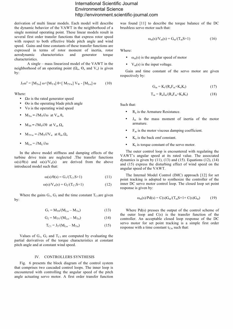
Fig. 8 presents the set point tracking and wind speed disturbance rejection responses of the DC servo motor without the introduction of the feed forward controller at 9 m/s nominal wind speed. Fig. 9 and Fig. 10 present the set point tracking and wind speed disturbance rejection responses of the VAWT’s rotor as well as the associated PID controller without the introduction of the feed forward controller at the same nominal wind speed.
Fig. 11 presents the set point tracking and wind speed disturbance rejection responses of the DC servo motor under the effect of the combined PI – feed forward control scheme at 9 m/s nominal wind speed. Fig. 12 and Fig. 13 present the set point tracking and wind speed disturbance rejection responses of the VAWT’s rotor as well as the associated output of the combined controller at the same nominal wind speed.
International Scientific Journal Environmental Science http://environment.scientific-journal.com

Fig. 7. Computation algorithm flow chart
Fig. 8. Servo motor speed without feed forward at 9 m/s wind speed
Fig. 9. Rotor angular speed without feed forward at 9 m/s wind speed
Fig. 10. Rotor’s controller output without feed forward at 9 m/s wind
speed
Fig. 11. Servo motor speed with feed forward at 9 m/s wind speed
Fig. 14 presents the set point tracking and wind speed disturbance rejection responses of the DC servo motor without the introduction of the feed forward controller at 13 m/s nominal wind speed. Fig. 15 and Fig. 16 present the set point tracking and wind speed disturbance rejection responses of the VAWT’s rotor as well as the associated PID controller without the introduction of the feed forward controller at the same nominal wind speed.
KR
Aerodynamic Model
PID Controller setting
First Order Model for Pitch Actuation Mechanism
First Order Transfer Functions (G1, G2 and TC1)
Numerical Evaluation of Torque Derivatives (∂M/∂V), (∂M/∂θ) and (∂M/∂ω)
Torque – Angular Speed Characteristics
Wind Speed
Feed Forward
PI of DC Motor
VAWT Rotor Blades
SP
ωm
θ
International Scientific Journal Environmental Science http://environment.scientific-journal.com
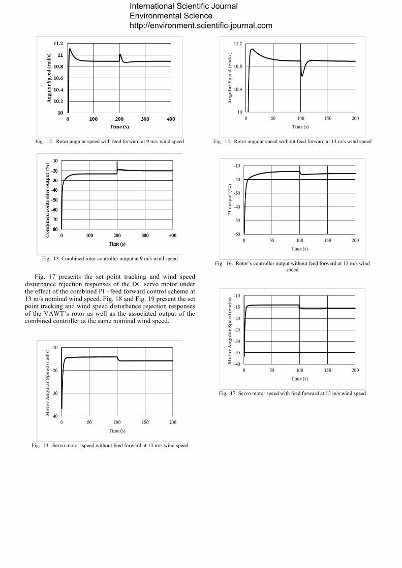
Fig. 12. Rotor angular speed with feed forward at 9 m/s wind speed
Fig. 13. Combined rotor controller output at 9 m/s wind speed
Fig. 17 presents the set point tracking and wind speed disturbance rejection responses of the DC servo motor under the effect of the combined PI –feed forward control scheme at 13 m/s nominal wind speed. Fig. 18 and Fig. 19 present the set point tracking and wind speed disturbance rejection responses of the VAWT’s rotor as well as the associated output of the combined controller at the same nominal wind speed.
Fig. 14. Servo motor speed without feed forward at 13 m/s wind speed
Fig. 15. Rotor angular speed without feed forward at 13 m/s wind speed
Fig. 16. Rotor’s controller output without feed forward at 13 m/s wind
speed
Fig. 17. Servo motor speed with feed forward at 13 m/s wind speed
International Scientific Journal Environmental Science http://environment.scientific-journal.com

Fig. 18. Rotor angular speed with feed forward at 13 m/s wind speed
Fig. 19. Combined controller output at 13 m/s wind speed
ACKNOWLEDGEMENT This research is supported by the EU-Egypt Innovation
fund through the RDI scheme 1 program, project No. ENP/2014/343-692
REFRENCES [1] R. Nobile, M. Vahdati, J. Barlow, A. Mewburn-Crook “Dynamic stall
for a Vertical Axis Wind Turbine in a two-dimensional study” world renewable energy congress –Sweden, May 2011
[2] Asress Mulugeta Biadgo ,“ Numerical and Analytical Investigation of Vertical Axis Wind Turbine”, Addis Ababa University, FME Transactions (2013) 41, 49-58
[3] Habtamu Beri, Yingxue Yao “Double Multiple Stream Tube Model and Numerical Analysis of Vertical Axis Wind Turbine”, Energy and Power Engineering, 2011, 3, 262-270, china
[4] RATHI, DHRUV. “Performance Prediction and Dynamic Model
Analysis of Vertical Axis Wind Turbine Blades with Aerodynamically Varied Blade Pitch”, North Carolina State University, North Carolina 2012.
[5] Sergio M. Camporealea, Vinicio Magib, “Streamtube model for analysis of vertical axis variable pitch turbine for marine currents energy conversion”, Energy Conversion & Management 41 (2000) 1811±1827.
[6] In Seong Hwang, Seung Yong Min, In Oh Jeong, Yun Han Lee and Seung Jo Kim, “Efficiency Improvement of a New Vertical Axis Wind Turbine by Individual Active Control of Blade Motion”, School of Mechanical & Aerospace Engineering, Seoul National University San 56-1, Sillim-dong, Gwanak-gu, Seoul, 151-742, Korea.
[7] MONTGOMERIE, B: Methods for Root Effects, Tip Effects and
Extending the Angle of Attack Range to ±180 deg, with Application to Aerodynamics for Blades on Wind Turbines and Propellers, FOI Swedish Defence Research Agency, Scientific Report FOI-R-1035-SE, 2004.
[8] Castelli, M. R., Englaro, A., & Benini, E. (2011). The Darrieus wind turbine: Proposal for a new performance prediction model based on CFD. El Sevier.
[9] Claessens, M. (2006). The Design and Testing of Airfoils for Application in Small Vertical Axis Wind Turbines. TU Delft.
[10] Kirke, B. K. (1998). Evaluation of Self Starting Wind Turbines for
Stand-Alone Applications. School of Engineering Griffith University Gold Coast Campus.
[11] P.Nagasekhar Reddy,” Modeling and Analysis of PI Controller Based
Speed Control of Brushless DC Motor Drive”, International Journal Of Engineering Sciences & Research Technology, Septemper 2013, [2226-2231]
[12] Siguad Skogestad,” Analytical rules for model reductionand PID
controller tuning” MODELING, IDENTIFICATION AND CONTROL,2004 Vol. 25 No 2,85-120
International Scientific Journal Environmental Science http://environment.scientific-journal.com