a novel algorithm for capacitor placement to improve voltage stability of radial and meshed power...
TRANSCRIPT

Journal of Information Engineering and Applications www.iiste.org
ISSN 2224-5782 (print) ISSN 2225-0506 (online)
Vol. 2, No.11, 2012
47
A Novel Algorithm for Capacitor Placement to improve Voltage
stability of Radial and Meshed Power Systems
G Rajendar (Corresponding author)
E-mail: [email protected]
Basavaraja Banakara
E-mail: [email protected], [email protected]
Abstract
The objective of this paper is to present a novel method for determining the optimum location and amount of reactive
power to be injected to improve the voltage stability of entire power system or set of buses that are prone to voltage
instability. A new sensitivity matrix named L-Index sensitivity matrix is been proposed and the same is considered
for identifying the buses, at which the reactive power is to be injected. The proposed procedure has been tested for
practical examples of radial networks and IEEE-14 bus system. Test results demonstrate the effectiveness of the
developed algorithm.
Keywords: L-index matrix, voltage stability, Jacobian matrix, sensitivity
1. Introduction
Voltage stability is concerned with the ability of the power system to maintain acceptable voltages at all the buses in
the system under the normal conditions and after being subjected to a disturbance. Once associated primarily with
weak systems and long lines, voltage problems are now also a source of concern in highly developed networks as a
result of heavier loadings.The review paper by Ajjarapu and Lee [8] presents an exhaustive list of work done in the
area of voltage stability till 1998. The phenomena which contributes to the voltage stability have been described, the
various countermeasures to avert it have been enumerated and the various computer analysis methods used or
proposed so far have been presented in a coherent way in [16].
2. Motivation
In 1997, a voltage instability problem in a distribution network, which spread to a corresponding
transmission system, had caused a major blackout in the S/SE Brazilian system [44]. Therefore over the years,
voltage stability of distribution systems has received great attention with a need for both analysis and enhancement
of the operating conditions. The Voltage Stability problem of radial distribution system from its single line
equivalent has been investigated and the voltage stability index (VSI) for identifying the node that is most sensitive
to voltage collapse has been developed in [20], [21] and [25]. The determination of the location, size, number and
type of capacitors to be placed are of great significance, as it reduces power and energy losses, increases the
available capacity of the feeders and improves the feeder voltage profile. Numerous methods for solving this
problem in view of minimizing losses have been suggested in the literature [[30]- [34]]. Algorithms for enhancing
voltage stability of transmission systems by optimal capacitor placement have been discussed [[35]- [36]]. A
relationship between voltage stability and loss minimization has been developed and the concept of maximizing
voltage stability through loss minimization has been outlined [[37]- [38]]. Algorithms for enhancing voltage stability
of distribution systems by network reconfiguration that alters the topological structure of the distribution feeders by
rearranging the status of switches have been suggested [[39]- [41]]. However, there is no work till date to improve
the stability of the system as a whole or to improve the stability of particular buses which are in our interest. In the
literature several indices are been proposed to indicate the voltage stability of power systems. The L-Index method is
proposed in [3] which attempts to provide a measure of the stability of the load buses in a system by ranking them
according to a parameter(L-Index). The eigenvalues and eigenvectors of the power flow jacobian have been used in
[22] to characterize the stability margin in a system. In this paper we are using L-Index [3] and Jacobin matrix [7] to
derive the L-Index sensitivity matrix denoted as ( qL ), which is used to calculate the optimal location of the
Journal of Information Engineering and Applications www.iiste.org
ISSN 2224-5782 (print) ISSN 2225-0506 (online)
Vol. 2, No.11, 2012
48
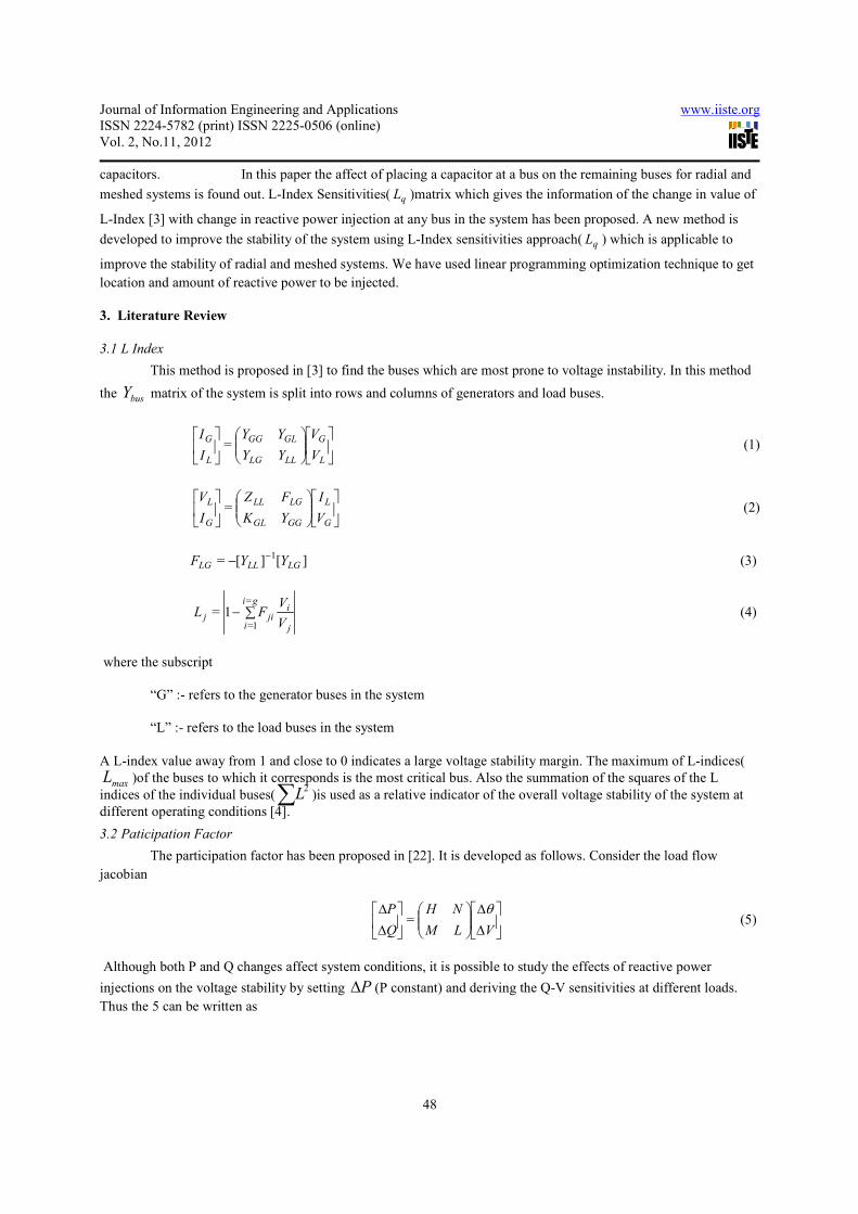
capacitors. In this paper the affect of placing a capacitor at a bus on the remaining buses for radial and
meshed systems is found out. L-Index Sensitivities( qL )matrix which gives the information of the change in value of
L-Index [3] with change in reactive power injection at any bus in the system has been proposed. A new method is
developed to improve the stability of the system using L-Index sensitivities approach( qL ) which is applicable to
improve the stability of radial and meshed systems. We have used linear programming optimization technique to get
location and amount of reactive power to be injected.
3. Literature Review
3.1 L Index
This method is proposed in [3] to find the buses which are most prone to voltage instability. In this method
the busY matrix of the system is split into rows and columns of generators and load buses.
L
G
LLLG
GLGG
L
G
V
V
YY
YY
I
I= (1)
G
L
GGGL
LGLL
G
L
V
I
YK
FZ
I
V= (2)
][][=1
LGLLLG YYF−− (3)
j
iji
gi
ij
V
VFL ∑−
=
1=
1= (4)
where the subscript
“G” :- refers to the generator buses in the system
“L” :- refers to the load buses in the system
A L-index value away from 1 and close to 0 indicates a large voltage stability margin. The maximum of L-indices(
maxL )of the buses to which it corresponds is the most critical bus. Also the summation of the squares of the L
indices of the individual buses(2L∑ )is used as a relative indicator of the overall voltage stability of the system at
different operating conditions [4].
3.2 Paticipation Factor
The participation factor has been proposed in [22]. It is developed as follows. Consider the load flow
jacobian
∆
∆
∆
∆
VLM
NH
Q
P θ= (5)
Although both P and Q changes affect system conditions, it is possible to study the effects of reactive power
injections on the voltage stability by setting P∆ (P constant) and deriving the Q-V sensitivities at different loads.
Thus the 5 can be written as
Journal of Information Engineering and Applications www.iiste.org
ISSN 2224-5782 (print) ISSN 2225-0506 (online)
Vol. 2, No.11, 2012
49
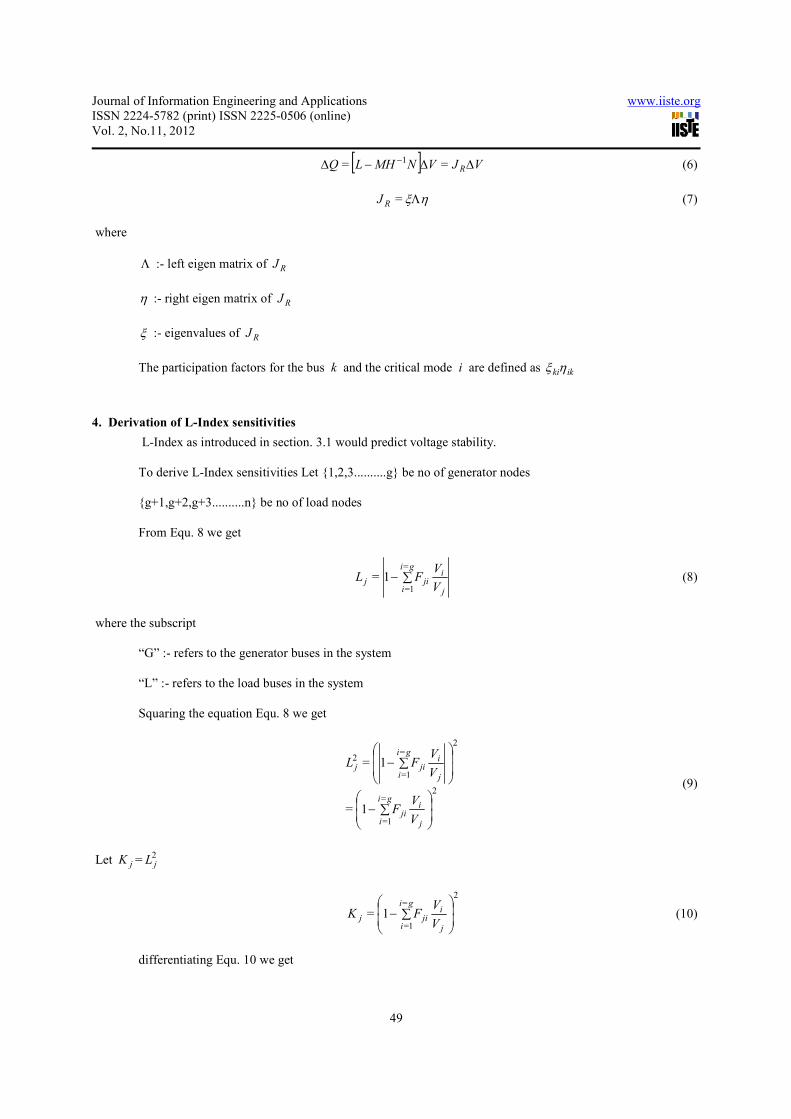
[ ] VJVNMHLQ R∆∆−∆ − == 1 (6)
ηξΛ=RJ (7)
where
Λ :- left eigen matrix of RJ
η :- right eigen matrix of RJ
ξ :- eigenvalues of RJ
The participation factors for the bus k and the critical mode i are defined as ikkiηξ
4. Derivation of L-Index sensitivities
L-Index as introduced in section. 3.1 would predict voltage stability.
To derive L-Index sensitivities Let {1,2,3..........g} be no of generator nodes
{g+1,g+2,g+3..........n} be no of load nodes
From Equ. 8 we get
j
iji
gi
ij
V
VFL ∑−
=
1=
1= (8)
where the subscript
“G” :- refers to the generator buses in the system
“L” :- refers to the load buses in the system
Squaring the equation Equ. 8 we get
2
=
1=
2=
1=
2
1=
1=
∑−
∑−
j
iji
gi
i
j
iji
gi
ij
V
VF
V
VFL
(9)
Let jK =2jL
2=
1=
1=
∑−
j
iji
gi
ij
V
VFK (10)
differentiating Equ. 10 we get

Journal of Information Engineering and Applications www.iiste.org
ISSN 2224-5782 (print) ISSN 2225-0506 (online)
Vol. 2, No.11, 2012
50
∑
∑−−
∆
∆2
=
1=
=
1=
12=j
iji
gi
ij
iji
gi
ij
j
V
VF
V
VF
V
K (11)
Taking the as already discussed in section we get
∆
∆
∆
∆
VLM
NH
Q
P θ= (12)
As the inclusion of an extra capacitor would change only the reactive power, we would make P∆ in Equ.12 equal
zero. From this we get
[ ] VJVNMHLQ R∆∆−∆ − == 1 (13)
QJV R ∆∆ −1][= (14)
where ][ RJ is the reduced jacobian.
where Q∆ is a vector of change in reactive power injections
Q∆ =[ 1+∆ gQ 2+∆ gQ 3+∆ gQ ..........]’
where V∆ is a vector of change in voltages
V∆ =[ 1+∆ gV 2+∆ gV 3+∆ gV ..........]’
Equ. 14 is very important as it gives us the relationship between the amount of reactive power injected at
any particular or set of buses and the change in voltage at all buses. Let
++
+++++
+++++
−
nngngn
nggggg
nggggg
R
aaa
aaa
aaa
J
,2,1,
2,22,12,
1,21,11,
1=
L
MOMM
L
L
(15)
From the Equ. 15, the voltage at a bus is given as
iji
ni
gij QaV ∆∑∆
+
=
1=
= (16)
manipulating Equ. 11 to get the change in voltage in terms of change in K
∑
∑−
∆−∆
2
=
1=
=
1=
12
=
j
iji
gi
ij
iji
gi
i
j
j
V
VF
V
VF
KV (17)
Substituting Equ. 21 in Equ. 20 we have
Journal of Information Engineering and Applications www.iiste.org
ISSN 2224-5782 (print) ISSN 2225-0506 (online)
Vol. 2, No.11, 2012
51
iji
gi
ij
iji
gi
ij
iji
gi
ij Qa
V
VF
V
VFK ∆∑
∑
∑−−∆
=
1=2
=
1=
=
1=
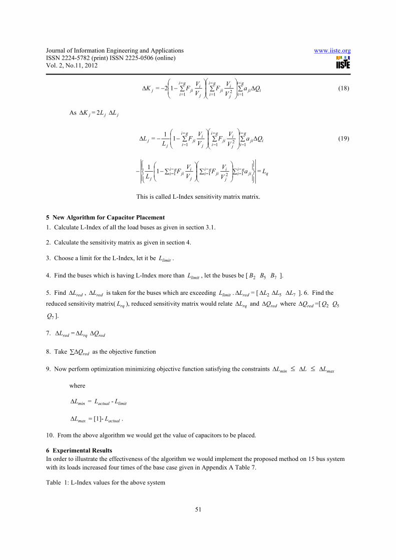
12= (18)
As jK∆ = jL2 jL∆
iji
gi
ij
iji
gi
ij
iji
gi
ijj Qa
V
VF
V
VF
LL ∆∑
∑
∑−−∆
=
1=2
=
1=
=
1=
11
= (19)
∑
∑
∑−− ji
gii
j
iji
gii
j
iji
gii
j
aV
VF
V
VF
L
=1=2
=1=
=1=1
1= qL
This is called L-Index sensitivity matrix matrix.
5 New Algorithm for Capacitor Placement
1. Calculate L-Index of all the load buses as given in section 3.1.
2. Calculate the sensitivity matrix as given in section 4.
3. Choose a limit for the L-Index, let it be limitL .
4. Find the buses which is having L-Index more than limitL , let the buses be [ 2B 5B 7B ].
5. Find redL∆ , redL∆ is taken for the buses which are exceeding limitL . redL∆ = [ 2L∆ 5L∆ 7L∆ ]. 6. Find the
reduced sensitivity matrix( rqL ), reduced sensitivity matrix would relate rqL∆ and redQ∆ where redQ∆ =[ 2Q 5Q
7Q ].
7. redL∆ = rqL∆ redQ∆
8. Take redQ∆∑ as the objective function
9. Now perform optimization minimizing objective function satisfying the constraints minL∆ ≤ L∆ ≤ maxL∆
where
minL∆ = actualL - limitL
maxL∆ = [1]- actualL .
10. From the above algorithm we would get the value of capacitors to be placed.
6 Experimental Results
In order to illustrate the effectiveness of the algorithm we would implement the proposed method on 15 bus system
with its loads increased four times of the base case given in Appendix A Table 7.
Table 1: L-Index values for the above system

Journal of Information Engineering and Applications www.iiste.org
ISSN 2224-5782 (print) ISSN 2225-0506 (online)
Vol. 2, No.11, 2012
52
From the above we get
iji
ni
gij QaV ∆∑∆
+
=
1=
= (20)
From Equ. 11
∑
∑−
∆∆
2
=
1=
=
1=
12
=
j
iji
gi
ij
iji
gi
i
j
j
V
VF
V
VF
KV (21)
Substituting Equ. 21in Equ. 20 we have
iji
gi
ij
iji
gi
ij
iji
gi
ij Qa
V
VF
V
VFK ∆∑
∑
∑−∆
=
1=2
=
1=
=
1=
12= (22)
Table 1:L Index values for the above system
Let us take limit for L-Index( limitL ) as 0.5
Bus no L-Index
2 0.24756
3 0.43962
4 0.53262
5 0.54971
6 0.40118
7 0.41826
8 0.27086
9 0.28973
10 0.55208
11 0.63254
12 0.66014
13 0.57359
14 0.57676
15 0.43143

Journal of Information Engineering and Applications www.iiste.org
ISSN 2224-5782 (print) ISSN 2225-0506 (online)
Vol. 2, No.11, 2012
53
Buses exceeding limitL are [ 4B 5B 10B 11B 12B 13B 14B ].
redL∆ =[ 4L∆ 5L∆ 10L∆ 11L∆ 12L∆ 13L∆ 14L∆ ].
Table 2: Reduced Sensitivity matrix of 15 bus experiment system
maxL∆ = [0.53262 0.54971 0.55208 0.63254 0.66014 0.57359 0.57676]
minL∆ =[0.032616 0.049709 0.052083 0.13254 0.16014 0.073588 0.076765]
Imposing the condition minL∆ ≤ L∆ ≤ maxL∆ and running optimization program we get values of capacitors as
given in Table 5. From the sensitivity matrix it can be seen that each row is having a maximum element in that row.
As each row is having a maximum element in it we can say that in order to have maximum influence on the bus
corresponding to that row we have to keep capacitor at the bus corresponding to the column of maximum element.
This would reduce the value of capacitor to be placed. To illustrate this let’s assume that bus no 11 in the system
whose sensitivity matrix is given above is more prone to voltage instability. Checking the row corresponding to 11th
bus in the sensitivity matrix it can be seen that 12th bus column element is having maximum value. Then keep the
capacitor at 12th bus to have maximum influence on 11th bus. If we keep capacitor at 12th bus as 11L∆ =
(12)(11,12) QLq ∆ so if (11,12)qL is maximum then (12)Q∆ will be minimum to get the same 11L∆ . Minimum
value of (12)Q∆ would correspond to minimum value of capacitor. so this would reduce the capacitor value if we
put the capacitor at 12th bus then on any other buses in the system.
4 5 10 11 12 13 14
4 0.18241 0.18657 0.16042 0.17813 0.18433 0.1925 0.1933
5 0.18861 0.22497 0.16587 0.18418 0.19059 0.19903 0.19986
10 0.16299 0.16671 0.20907 0.23326 0.24174 0.172 0.17272
11 0.19035 0.19469 0.24416 0.33598 0.34864 0.20087 0.20171
12 0.20023 0.20479 0.25683 0.35342 0.41922 0.2113 0.21218
13 0.19758 0.20208 0.17377 0.19295 0.19966 0.25867 0.20937
14 0.1988 0.20333 0.17484 0.19414 0.2009 0.2098 0.23782

Journal of Information Engineering and Applications www.iiste.org
ISSN 2224-5782 (print) ISSN 2225-0506 (online)
Vol. 2, No.11, 2012
54
Table 3: Sensitivity matrix of 15 bus experiment system
In order to show the consistency of the L-Index sensitivities method we have calculated L∆ for the 15 bus system
given in Fig.1 keeping the capacitor of 120kVAR at bus 12 from L-Index sensitivities method. L∆ is calculated as
2 3 4 5 6 7 8 9 10 11 12 13 14
2 0.03392
8
0.04792
9
0.05472
4
0.05597 0.04346 0.04454
8
0.03524 0.03631
3
0.05621
5
0.06242 0.06459
2
0.05774
9
0.05798
9
0.045403
3 0.05527
3
0.11262 0.12859 0.13152 0.07080
2
0.07257
5
0.05741 0.05915
8
0.1321 0.14668 0.15178 0.1357 0.13626 0.073967
4 0.06712
7
0.13678 0.18241 0.18657 0.08598
6
0.08813
9
0.06972
2
0.07184
6
0.16042 0.17813 0.18433 0.1925 0.1933 0.08983
5 0.06940
7
0.14142 0.18861 0.22497 0.08890
7
0.09113
3
0.07209 0.07428
6
0.16587 0.18418 0.19059 0.19903 0.19986 0.092882
6 0.04899
5
0.06921
3
0.07902
6
0.08082
5
0.10904 0.11204 0.05088
9
0.05243
9
0.08117
9
0.09013
9
0.09327
6
0.08339
4
0.08374
1
0.11439
7 0.05081
5
0.07178
5
0.08196
3
0.08382
9
0.1131 0.13642 0.05278 0.05438
8
0.08419
6
0.09348
9
0.09674
3
0.08649
3
0.08685
3
0.11864
8 0.03589
1
0.05070
2
0.05789
1
0.05920
9
0.04597
5
0.04712
6
0.05705
6
0.05895
3
0.05946
8
0.06603
2
0.06833 0.06109
1
0.06134
5
0.04803
9 0.03752
2
0.05300
7
0.06052
2
0.0619 0.04806
5
0.04926
8
0.05964
9
0.08617
4
0.06217
1
0.06903
3
0.07143
6
0.06386
7
0.06413
3
0.050213
1
0
0.07006 0.14275 0.16299 0.16671 0.08974
3
0.09199
1
0.07276
9
0.07498
5
0.20907 0.23326 0.24174 0.172 0.17272 0.093755
1
1
0.08181
9
0.16671 0.19035 0.19469 0.10481 0.10743 0.08498
2
0.08757 0.24416 0.33598 0.34864 0.20087 0.20171 0.1094
1
2
0.08606
5
0.17537 0.20023 0.20479 0.11025 0.11301 0.08939
3
0.09211
5
0.25683 0.35342 0.41922 0.2113 0.21218 0.11517
1
3
0.07270
9
0.14815 0.19758 0.20208 0.09313
8
0.09547 0.07552
1
0.07782
1
0.17377 0.19295 0.19966 0.25867 0.20937 0.097301
1
4
0.07315
9
0.14907 0.1988 0.20333 0.09371
4
0.09606 0.07598
8
0.07830
2
0.17484 0.19414 0.2009 0.2098 0.23782 0.097903
1
5
0.05226
2
0.07382
9
0.08429
6
0.08621
6
0.11632 0.11951 0.05428
3
0.05593
6
0.08659
3
0.09615
1
0.09949
7
0.08895
6
0.08932
6
0.14031

Journal of Information Engineering and Applications www.iiste.org
ISSN 2224-5782 (print) ISSN 2225-0506 (online)
Vol. 2, No.11, 2012
55
L-Index(with capacitor)-L-Index(without capacitor) from the conventional method as given in Section ??. Values of
L∆ from both methods is tabulated in Table 4.
Table 4: Comparision of L∆ from both methods
Bus no L∆ from L-Index
sensitivities
L∆ from conventional
method
2 0.001561375 0.00153235
3 0.002982529 0.002926712
4 0.003036517 0.002977799
5 0.003045882 0.002986667
6 0.001625685 0.00159306
7 0.001632134 0.001599146
8 0.001577317 0.001547467
9 0.001582524 0.001552402
10 0.004477482 0.004394593
11 0.006484893 0.006368077
12 0.008109174 0.007966572
13 0.003058382 0.002998492
14 0.003059996 0.003000017
14 0.001636937 0.001603675
From the Table 4 it can be seen that the values of L∆ as obtained from the both methods are very much close to
each other so we can conclude that L-Index sensitivities method derived in section 4 is correct.
Journal of Information Engineering and Applications www.iiste.org
ISSN 2224-5782 (print) ISSN 2225-0506 (online)
Vol. 2, No.11, 2012
56
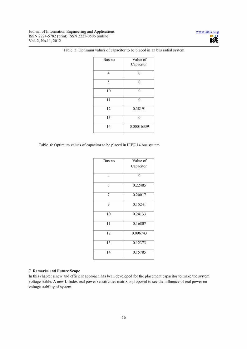
Table 5: Optimum values of capacitor to be placed in 15 bus radial system
Bus no Value of
Capacitor
4 0
5 0
10 0
11 0
12 0.38191
13 0
14 0.00016339
Table 6: Optimum values of capacitor to be placed in IEEE 14 bus system
Bus no Value of
Capacitor
4 0
5 0.22485
7 0.20017
9 0.15241
10 0.24133
11 0.16807
12 0.096743
13 0.12373
14 0.15785
7 Remarks and Future Scope
In this chapter a new and efficient approach has been developed for the placement capacitor to make the system
voltage stable. A new L-Index real power sensitivities matrix is proposed to see the influence of real power on
voltage stability of system.

Journal of Information Engineering and Applications www.iiste.org
ISSN 2224-5782 (print) ISSN 2225-0506 (online)
Vol. 2, No.11, 2012
57
8 Conclusions
This paper is essentially concerned with the analyzing and improvement of voltage stability of radial power systems.
Most of the indices which have been proposed for assessing voltage stability are studied. Shortcomings in Line Flow
Index are identified. Patterns of voltage stability indices are been observed and their dependence on the electrical
distance has been studied. A better comparison has been made by exploiting several unique features of radial power
systems. Effect of loads, distance of the load bus from the slack bus and structure of the network on the voltage
stability is investigated.
A new algorithm is found to optimally place the capacitors to improve the voltage stability to the required level. The
effect of reactive power injections at a bus on the entire power system in consideration is studied. A new sensitivity
matrix( pL ) which would relate the change in real power effect on the voltage stability is proposed. Buses at which
the capacitors have to be placed to improve the voltage stability are identified.
The algorithms which have been proposed for radial power systems can be suitably modified and can be applied to
meshed systems. The effect of real power on the L-Index has to be studied in more detail. We can a develop an index
which can predict the maximum column element in a given row of L-Index sensitivity matrix( qL ) with out looking
at the matrix.
References
Ajjarapu V &Lee. B (February 1998) Biliography on voltage Stability, IEEE Transactions on Power Systems
Defination & Classification of Power System Stability(May 2004), IEEE Transactions on Power Systems
Grangier J.J &Stevenson W.D(1994) Power System Analysis, McGraw-Hill,
Gubina F. & Strmcnik B(May 1995)B Voltage Collapse Proximity Index Determination Using Voltage Phasors
Approach,IEEE transactions on power systems,
Guideliness for Enchancing Power Plant Response to Partial Load Rejections(June 1983) IEEE Transactions on
Power Apparatus and Systems.
Kessel. P &Glavitsch.H(July 1986) Estimating the voltage stability of power system, IEEE Transactions on Power
Delivery.
Kundur. P D, Lee C, Bayne J.P. & Dandeno. P.L(June 1985) Impact of Turbine Generator Controls on Unit
Performance under System Disturbance Conditions, IEEE Transactions on Power Apparatus and Systems.
Kurita A.& Sakurai. T.(December 1988) The Power System Failure on July 23, 1987 in Tokyo, Proceedings of the
27th IEEE conference on Decision and Control, Austin, Texas.
Lof. P.A(Sweden, 1995) On Static Analysis of Long-term Voltage Stability, PhD Thesis, Royal Institute of
Technology, Stockholm,.
Prabha Kundur, John Paserba, Venkat Ajjarapu, Gran Andersson, Anjan Bose, Claudio Canizares, Nikos
Hatziargyriou, David Hill, Alex Stankovic, Carson Taylor, Therry Van Cutsem and Vijay Vittal.
Sami Repo(September 2001) Online voltage Stability Assessment of Power System - An Approach of Black-Box
Modelling, Publications 344, Tampere Universityof Technology,

Journal of Information Engineering and Applications www.iiste.org
ISSN 2224-5782 (print) ISSN 2225-0506 (online)
Vol. 2, No.11, 2012
58
Taylor C.W &.Erickson D.C(January 1997) Recording and Analysing the July 2 Cascading Outage, IEEE
Computer Applicatins in Power.
Theirry Van Cutsem.( February 2000) Voltage Instability: Phenomena,Countermeasures, and Analysis methods,
Proceedings of the IEEE.
Thierry Van Cutsem & Costas Vournas(1998). Voltage Stability of Electric Power Systems, Kluwer Academic
Publishers,.
Thukkaram D & Abraham Lomi(May 2000). Selection of static VAR compensator Location and size for System
Voltage Stability Improvement, Electrical Power Systems Research
Weedy B.M. & Cox B.R(April 1968). Voltage Stability of Radial Power Links, Proceedings of IEE.
G.Rajendar from KITS,Warangal, India. He is working as Associate Professor in the Department of Electrical . His
areas of interests are Voltage stability , and Applications of Power Electronics to Power Systems. Presently he is
Research Scholar at JNTU,Hyderabad India in Electrical and Electronics Department
Dr. Basavaraja Banakara, ME, MBA(HR), PhD (NITW) .He is working as Vice Principal & HOD ,GITAM
UNIVERSITY,Hyderabad . His areas of interests are Power Electronics Applications in Power Systems, Power
System Stability Control.

This academic article was published by The International Institute for Science,
Technology and Education (IISTE). The IISTE is a pioneer in the Open Access
Publishing service based in the U.S. and Europe. The aim of the institute is
Accelerating Global Knowledge Sharing.
More information about the publisher can be found in the IISTE’s homepage:
http://www.iiste.org
CALL FOR PAPERS
The IISTE is currently hosting more than 30 peer-reviewed academic journals and
collaborating with academic institutions around the world. There’s no deadline for
submission. Prospective authors of IISTE journals can find the submission
instruction on the following page: http://www.iiste.org/Journals/
The IISTE editorial team promises to the review and publish all the qualified
submissions in a fast manner. All the journals articles are available online to the
readers all over the world without financial, legal, or technical barriers other than
those inseparable from gaining access to the internet itself. Printed version of the
journals is also available upon request from readers and authors.
IISTE Knowledge Sharing Partners
EBSCO, Index Copernicus, Ulrich's Periodicals Directory, JournalTOCS, PKP Open
Archives Harvester, Bielefeld Academic Search Engine, Elektronische
Zeitschriftenbibliothek EZB, Open J-Gate, OCLC WorldCat, Universe Digtial
Library , NewJour, Google Scholar