a new lab facility for measuring bidirectional …
TRANSCRIPT

A NEW LAB FACILITY FOR MEASURING BIDIRECTIONAL REFLECTANCE/EMITTANCE DISTRIBUTION FUNCTIONS OF
SOILS AND SMALL CANOPIES
J.G.P.W. Clevers a, *, H.M. Bartholomeus
a, M.E. Schaepman
b, G. Schaepman-Strub
b, H. Jalink
c, R. van der Schoor
c,
A. de Jong d
, M. Uiterwijk d
a Laboratory of Geo-Information Science and Remote Sensing, Wageningen University, P.O. Box 47, 6700 AA Wageningen,
The Netherlands (jan.clevers, harm.bartholomeus)@wur.nl b University of Zurich, Winterthurerstrasse 190, CH-8057 Zurich, Switzerland
c Wageningen UR Greenhouse Horticulture, P.O. Box 644, 6700 AP Wageningen, The Netherlands
d Alterra, Wageningen University & Research Centre, P.O. Box 47, 6700 AA Wageningen, The Netherlands
KEYWORDS: Lab facility, anisotropy, reflectance, BRDF, spectroradiometer, emittance, BTDF, thermal imager. ABSTRACT: Recently, a laboratory measurement facility has been realized for assessing the anisotropic reflectance and emittance behaviour of soils, leaves and small canopies under controlled illumination conditions. The facility consists of an ASD FieldSpec 3 spectroradiometer covering the spectral range from 350 – 2500 nm at 1 nm spectral sampling interval. The spectroradiometer is deployed using a fiber optic cable with either a 1°, 8° or 25° instantaneous field of view (IFOV). These measurements can be used to assess the plant pigment (chlorophyll, xanthophyll, etc.) and non-pigment system (water, cellulose, lignin, nitrogen, etc.). The thermal emittance is measured using a NEC TH9100 Infrared Thermal Imager. It operates in a single band covering the spectral range from 8 – 14 µm with a resolution of 0.02 K. Images are 320 (H) by 240 (V) pixels with an IFOV of 1.2 mrad. A 1000 W Quartz Tungsten Halogen (QTH) lamp is used as illumination source, approximating the radiance distribution of the sun. This one is put at a fixed position during a measurement session. Multi-angular measurements are achieved by using a robotic positioning system allowing to perform either reflectance or emittance measurements over almost a complete hemisphere. The hemisphere can be sampled continuously between 0° and 80° from nadir and up to a few degrees from the hot-spot configuration (depending on the IFOV of the measurement device) for a backscattering target. Measurement distance to targets can be varied between 0.25 and 1 m, although with a distance of more than 0.6 m it is not possible to cover the full hemisphere. The goal is to infer the BRDF (bidirectional reflectance distribution function) and BTDF (bidirectional thermal distribution function) from these multi-angular measurements for various surface types (like soils, agricultural crops, small tree canopies and artificial objects) and surface roughness. The steering of the robotic arm and the reading of the spectroradiometer and the thermal camera are all fully automated.
1. INTRODUCTION
A laboratory set-up has been realized for assessing the reflectance and emittance anisotropy of soils, leaves and small canopies under controlled solar illumination conditions. These measurements can be used to assess e.g. the plant pigment (chlorophyll, xanthophyll, etc.) and non-pigment system (water, cellulose, lignin, nitrogen, etc.). Photosynthesis of terrestrial vegetation is an important component of the global carbon cycle, and is closely linked to the hydrological cycle through transpiration. Currently there are no direct ways to measure photosynthesis by means of remote sensing. The main requirement for instruments is to measure high spectral resolution reflectance, temperature, and provide a multi-angular capability. These measurements are expressed as BRDF (bidirectional reflectance distribution function) and BTDF (bidirectional thermal distribution function). Currently, a variety of facilities exist to measure these functions, however they are in all cases single instrumentation based (e.g., BRDF: Univ. of Zurich (CH) (Sandmeier and Itten, 1999), BTDF: ITC (NL) (Timmermans et al., 2009)), and cannot assess the combined properties. We have acquired expertise in the measurement and modelling of spectro-directional behaviour of soils, leaves and canopies over the past decades. To acquire narrowband spectral reflectance, we have several non-imaging spectrometers available as well as appropriate models to simulate leaf optical properties up to canopy functioning. Furthermore, a thermal imaging system is available to determine the emission of objects. The combined set of instruments covers the wavelengths from the solar reflected range (400-2500 nm) up to the thermal emitted range (8-14 µm). In this paper the elements of the lab facility for combined measurement of multi-angular reflectance and thermal emittance are described.
* Corresponding author.

2. MATERIAL AND METHODS
The core of the goniometer system is formed by an industrial robot arm, on which the different sensors are mounted. Figure 1 illustrates the basic set-up of the lab facility with an ASD FieldSpec 3 spectroradiometer attached to the robotic positioning system performing multi-angular reflectance measurements over a small plant. In the following subsections the components of the system will be described.
Figure 1. Illustration of the set-up of the lab facility. 2.1 KAWASAKI FS 10E Robot
The robotic system consists of a Kawasaki FS10E industrial robot and has the following main characteristics: • 6 Movement axes • Working radius 1550 mm • Lifting capacity 10 kg • Position repeatability ± 0.1 mm
The robot arm can be fully programmed in 2 modes:
1) Dome mode • From -90° - +90° off nadir • Dome radius can be varied from 25 cm up to 100 cm (although some positions cannot be reached at larger dome
sizes) • Theoretically unlimited positions on the dome • Programmed to measure around the hot-spot
2) Scan mode • Movement of the sensor in the horizontal plane • Grid spacing programmable • Height can be varied
2.2 Illumination
A 1000 W Quartz Tungsten Halogen (QTH) lamp is used as artificial light source. QTH lamps are popular visible and near-infrared sources because of their smooth spectral curve and stable output (figure 2). They do not have sharp spectral peaks like some other sources have. The colour temperature is above 3000 K.
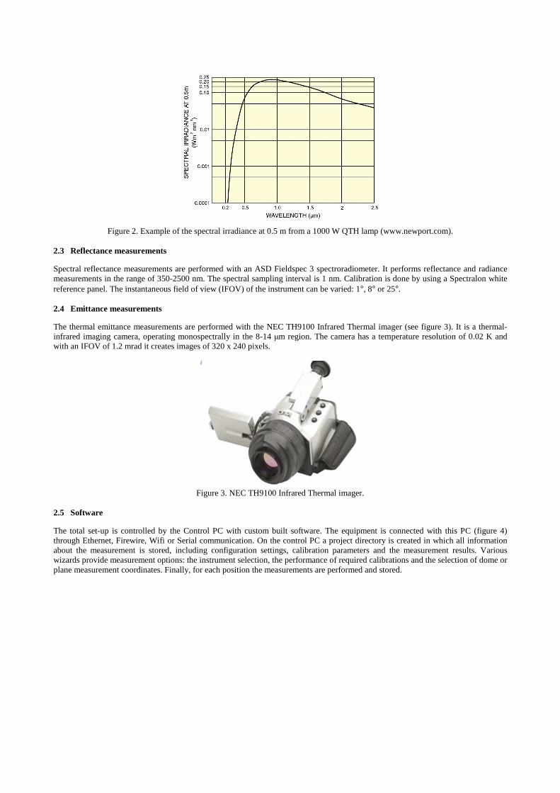
Figure 2. Example of the spectral irradiance at 0.5 m from a 1000 W QTH lamp (www.newport.com).
2.3 Reflectance measurements
Spectral reflectance measurements are performed with an ASD Fieldspec 3 spectroradiometer. It performs reflectance and radiance measurements in the range of 350-2500 nm. The spectral sampling interval is 1 nm. Calibration is done by using a Spectralon white reference panel. The instantaneous field of view (IFOV) of the instrument can be varied: 1°, 8° or 25°. 2.4 Emittance measurements
The thermal emittance measurements are performed with the NEC TH9100 Infrared Thermal imager (see figure 3). It is a thermal-infrared imaging camera, operating monospectrally in the 8-14 µm region. The camera has a temperature resolution of 0.02 K and with an IFOV of 1.2 mrad it creates images of 320 x 240 pixels.
Figure 3. NEC TH9100 Infrared Thermal imager.
2.5 Software
The total set-up is controlled by the Control PC with custom built software. The equipment is connected with this PC (figure 4) through Ethernet, Firewire, Wifi or Serial communication. On the control PC a project directory is created in which all information about the measurement is stored, including configuration settings, calibration parameters and the measurement results. Various wizards provide measurement options: the instrument selection, the performance of required calibrations and the selection of dome or plane measurement coordinates. Finally, for each position the measurements are performed and stored.

Control PC
NEC Thermal imager
ASD Lens
ASD Fieldspec 3 Spectrometer
Fibre optic cable
Halogen lamp
Ethernet Switch
Firewire
Ethe
rne t
Ethernet
Robot
Wi fi
Data Storage
RS2
32
Figure 4. Topology of the lab facility.
3. FIRST RESULTS
Figure 5 shows an example of a reflectance anisotropy plot for a small canopy (cf. figure 1). To the left the 3D representation is presented, whereas to the right the contour plot is given. The reflectance at 900 nm is shown. Figure 6 shows an example of a thermal image of the same canopy observed from nadir position (left) and from an oblique angle (right).
Figure 5. Polar plots of the relative directional reflectance of a small plant. Left: 3D polar plot. Right: Contour plot.

Figure 6. Illustration of a thermal image from nadir (left) and at an oblique angle (right).
4. CONCLUSIONS
In this paper, a laboratory facility for performing multi-angular measurements has been described. This set-up enables both multi-angular reflectance and thermal emittance measurements of soil, leaves and small canopies. For small FOVs, these measurements approximate the BRDF (bidirectional reflectance distribution function) and BTDF (bidirectional thermal distribution function) (Schaepman-Strub et al., 2006). First measurements are shown. As a next step, further measurements have to be evaluated before entering a phase of practical use.
REFERENCES
Sandmeier, S.R. and K.I. Itten, 1999. A field goniometer system (FIGOS) for acquisition of hyperspectral BRDF data. Ieee Transactions on Geoscience and Remote Sensing, 37(2 II), pp. 978-986.
Schaepman-Strub, G., M.E. Schaepman, T.H. Painter, S. Dangel and J.V. Martonchik, 2006. Reflectance quantities in optical remote sensing-definitions and case studies. Remote Sensing of Environment, 103(1), pp. 27-42.
Timmermans, J., A.S.M.A. Gieske, C. van der Tol, W. Verhoef and Z. Su, 2009. Automated directional measurement system for the acquisition of thermal radiative measurements of vegetative canopies. Sensors, 9(3), pp. 1409-1422.