a new approach of offline parameters estimation for vector
TRANSCRIPT

A New Approach of Offline Parameters Estimation for
Vector Controlled Induction Motor Drive
Krishna R More*, P N Kapil** and Hormaz Amrolia*** * Department of Electrical Engineering, Institute of Technology, Nirma University, Ahmedabad, India
[email protected] ** Department of Electrical Engineering, Institute of Technology, Nirma University, Ahmedabad, India
[email protected] ***Department of Electrical Engineering, Institute of Technology, Nirma University, Ahmedabad, India
Abstract: For efficient performance of any vector controlled drive, motor parameters are to be estimated with utmost accuracy. Offline and online parameter estimation techniques are generally used for estimating parameters. In this paper, the offline technique is adopted due to its advantage over latter technique. Under offline parameter estimation, the new strategy is simulated for estimating the machine parameters. Inverter test and single phase test are used for estimating parameters. Only three switches of the inverter are used for estimating parameters in inverter test and four switches in single phase test. These tests are easy to implement with no extra hardware, no mechanical job is required and equations are easy to understand and implement. These tests are simulated in MATLAB Simulink and parameters obtained are compared with actual parameters of machine model available in MATLAB Simulink. Keywords: Offline parameter estimation, inverter test, single phase test, dc resistance test, open circuit test, locked rotor test. Introduction Induction motors are widely used the electric machines in high-performance drive applications. Vector control of induction motor requires a precise knowledge of the motor parameters for its efficient operation. Numerous methods for estimating induction machine parameters such as online and offline parameter estimation have been developed exclusively for application in high-performance drives. Any vector controlled induction motor drive is inverter fed, numerous tests based on an inverter supply have been developed in recent past for determination of the required parameter values. Such methods are called offline parameter identification methods. Numerous possibilities exist nowadays to update the parameter values during the drive operation, termed as online parameter estimation methods [1], [2], [3]. Offline parameter estimation technique is adopted, as parameters are estimated at the initial stage itself with the inverter and then the estimated parameters are used in the system. There is no need to sense the signals continuously in offline parameter estimation, in order to estimate parameters as it is mandatory in online parameter estimation. No standard tests like an open circuit, locked rotor test are required where the mechanical task is required to estimate the parameters. Moreover, for estimating parameters offline, no PI controller is required. So, hardware requirement reduces. The only inverter, sensors, and controller are required in this technique. Offline parameter estimation technique uses inverter test and single phase test for estimating machine parameters. Inverter test for Rs, Ls and single phase test for Lls, Lm and Rr. Parameter Estimation Tests An equivalent circuit of induction motor valid for steady state is shown in Fig. 1.The circuit is composed of two resistors, the stator resistance (Rs) and the rotor resistance (Rr), and three ideal inductors, the stator leakage inductance (Lls), the rotor leakage inductance (Llr) and the magnetizing inductance (Lm). The stator voltage is represented by Vs and s is the slip frequency normalized with respect to the stator frequency. The purpose of this work is to measure the values of these five ideal components. Traditional Parameter Estimation Tests DC Resistance Measurement DC Measurement test is used to determine the stator resistance (Rs). This test consists of applying a DC voltage to stator winding. The DC voltage (Vdc) and current (Idc) are measured and Rs value is computed by dividing both measurements. Basically, a dc voltage is applied to the stator windings of an induction motor. Because the current is dc, there is no induced

68 Seventh International Conference on Advances in Power Electronics and Instrumentation Engineering – PEIE 2016
Figure 1: Steady State Induction Motor per phase equivalent circuit voltage in the rotor circuit and no resulting rotor current. Also, the reactance of the motor is zero at direct current. Therefore, the only quantity limiting current now in the motor is the stator resistance, and that resistance can be determined. The basic circuit for the dc test is shown in Fig. 2 where, dc power supply connected to two of the three terminals of a Y-connected induction motor. [6]
dc
dcs I
VR2
(1)
Figure 2: DC Resistance Test No Load Test Input power and motor current are measured at different voltage levels. Motor current and input power at rated voltage is called as no load current (Inl) and no load power (Pnl) respectively. Motor no-load resistance, no load impedance, and no load reactance can be calculated. No load test is performed to calculate no load (stator) reactance (Xnl) or stator inductance (Ls). The motor is allowed to run at rated voltage and allowed to reach rated speed on no-load. The equation to measure (Xnl) is given below (equ.2). The equivalent circuit of induction motor under a no-load condition is shown below in Fig. 3. The simulation arrangement for open circuit test is also shown below in Fig. 4 [5].
2IQX nl
(2)
22 )()( aaa PIVQ
(3) where, Q = Reactive Power, Va = Phase Voltage, Ia = Phase Current, Pa = Active power per phase, Xnl = No-Load Reactance

A New Approach of Offline Parameters Estimation for Vector Controlled Induction Motor Drive 69
Figure 3: Three phase equivalent circuit of induction motor under no load condition
Figure 4: Simulation arrangement for induction motor under no load condition
Locked Rotor Test Motor phase to phase voltage and input power at rated current are called as locked rotor voltage (Vlr) and locked rotor power (Plr). Motor locked rotor resistance (Rr), locked rotor impedance (Zr) and locked rotor reactance (Xr) can be calculated. Fig.5 shows the behavior of an induction motor under locked rotor test. Locked rotor test is performed to obtain stator leakage reactance (Xls) (equ.4) basically stator leakage inductance (Lls) is estimated (equ.5), magnetizing reactance (Xm) i.e. magnetizing inductance (Lm) can be estimated from (equ.6) and (equ.7) respectively. Rotor resistance (Rr) is estimated by using Xls, Xm and R2 (equ.11). In this test, the motor is allowed to run at a voltage less than the rated voltage till the rated current flows through the windings. Another way to estimate Rr is by using power factor (equ.12) and (equ.13). The simulation arrangement for locked rotor test is also shown below Fig.6 [5].

70 Seventh International Conference on Advances in Power Electronics and Instrumentation Engineering – PEIE 2016
Figure 5: Simplified equivalent circuit of three phase induction motor under locked rotor test
Figure 6: Simulation arrangement for induction motor under locked rotor condition The equations for estimating various parameters are mentioned below:-
2*3.0IQX ls (4)
where, Q is Reactive Power Here, 0.3 factor to be multiplied for the class C motor [4].
fX
fX
LL lrlslrls 22
(5)
lsnlm XXX (6)
fX
L mm 2
(7)
mlss LLL (8)
A New Approach of Offline Parameters Estimation for Vector Controlled Induction Motor Drive 71
2IPR
(9)
where, P is Active Power
sRRR 2 (10)
2
2 *
m
mlsr X
XXRR
(11)
IVP
as **3
cos
(12)
)(* lsrsssca jXRRIV (13)
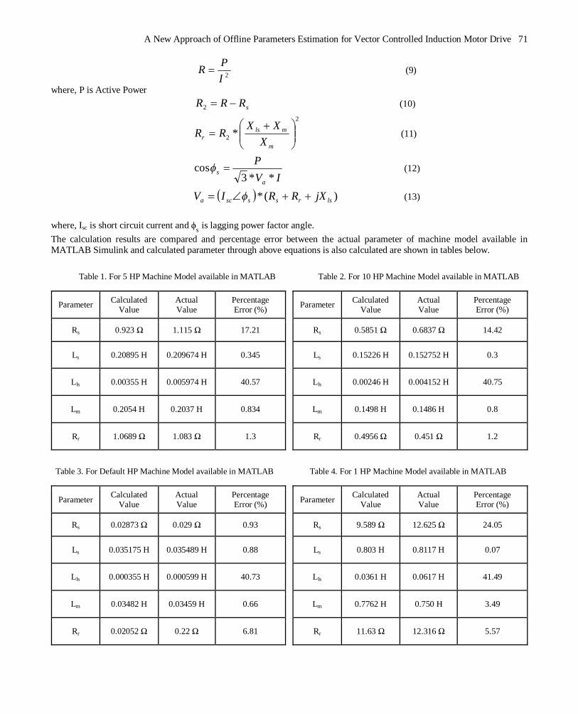
where, Isc is short circuit current and ϕs is lagging power factor angle. The calculation results are compared and percentage error between the actual parameter of machine model available in MATLAB Simulink and calculated parameter through above equations is also calculated are shown in tables below.
Table 1. For 5 HP Machine Model available in MATLAB
Parameter Calculated Value
Actual Value
Percentage Error (%)
Rs 0.923 Ω 1.115 Ω 17.21
Ls 0.20895 H 0.209674 H 0.345
Lls 0.00355 H 0.005974 H 40.57
Lm 0.2054 H 0.2037 H 0.834
Rr 1.0689 Ω 1.083 Ω 1.3
Table 2. For 10 HP Machine Model available in MATLAB
Parameter Calculated Value
Actual Value
Percentage Error (%)
Rs 0.5851 Ω 0.6837 Ω 14.42
Ls 0.15226 H 0.152752 H 0.3
Lls 0.00246 H 0.004152 H 40.75
Lm 0.1498 H 0.1486 H 0.8
Rr 0.4956 Ω 0.451 Ω 1.2
Table 3. For Default HP Machine Model available in MATLAB
Parameter Calculated Value
Actual Value
Percentage Error (%)
Rs 0.02873 Ω 0.029 Ω 0.93
Ls 0.035175 H 0.035489 H 0.88
Lls 0.000355 H 0.000599 H 40.73
Lm 0.03482 H 0.03459 H 0.66
Rr 0.02052 Ω 0.22 Ω 6.81
Table 4. For 1 HP Machine Model available in MATLAB
Parameter Calculated Value
Actual Value
Percentage Error (%)
Rs 9.589 Ω 12.625 Ω 24.05
Ls 0.803 H 0.8117 H 0.07
Lls 0.0361 H 0.0617 H 41.49
Lm 0.7762 H 0.750 H 3.49
Rr 11.63 Ω 12.316 Ω 5.57
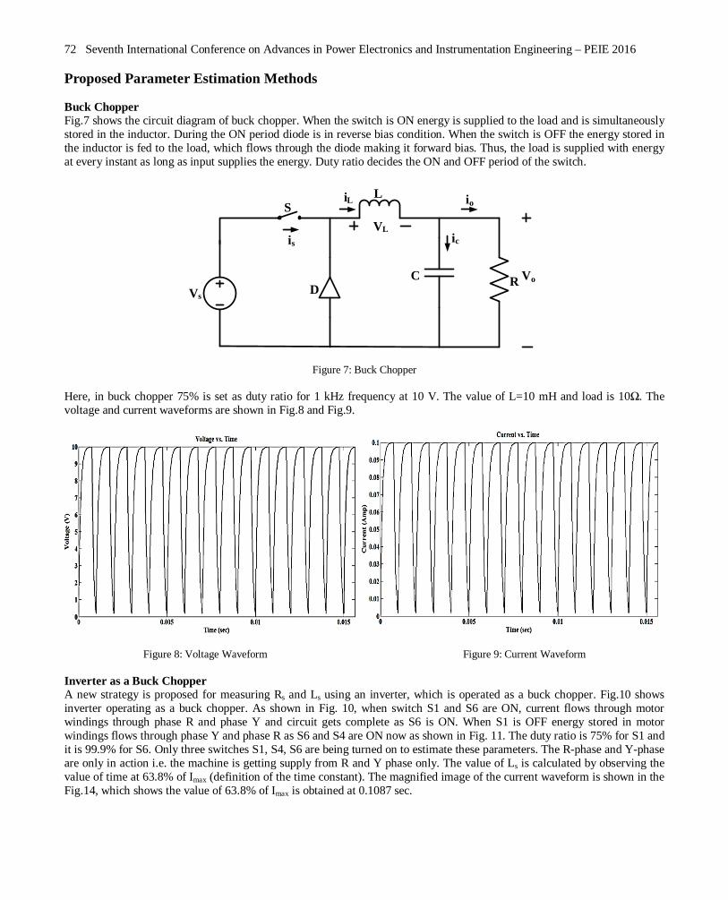
72 Seventh International Conference on Advances in Power Electronics and Instrumentation Engineering – PEIE 2016 Proposed Parameter Estimation Methods Buck Chopper Fig.7 shows the circuit diagram of buck chopper. When the switch is ON energy is supplied to the load and is simultaneously stored in the inductor. During the ON period diode is in reverse bias condition. When the switch is OFF the energy stored in the inductor is fed to the load, which flows through the diode making it forward bias. Thus, the load is supplied with energy at every instant as long as input supplies the energy. Duty ratio decides the ON and OFF period of the switch.
VsRC
D
S
Vo
L
is
iL io
icVL
Figure 7: Buck Chopper Here, in buck chopper 75% is set as duty ratio for 1 kHz frequency at 10 V. The value of L=10 mH and load is 10Ω. The voltage and current waveforms are shown in Fig.8 and Fig.9.
Figure 8: Voltage Waveform Figure 9: Current Waveform Inverter as a Buck Chopper A new strategy is proposed for measuring Rs and Ls using an inverter, which is operated as a buck chopper. Fig.10 shows inverter operating as a buck chopper. As shown in Fig. 10, when switch S1 and S6 are ON, current flows through motor windings through phase R and phase Y and circuit gets complete as S6 is ON. When S1 is OFF energy stored in motor windings flows through phase Y and phase R as S6 and S4 are ON now as shown in Fig. 11. The duty ratio is 75% for S1 and it is 99.9% for S6. Only three switches S1, S4, S6 are being turned on to estimate these parameters. The R-phase and Y-phase are only in action i.e. the machine is getting supply from R and Y phase only. The value of Ls is calculated by observing the value of time at 63.8% of Imax (definition of the time constant). The magnified image of the current waveform is shown in the Fig.14, which shows the value of 63.8% of Imax is obtained at 0.1087 sec.

A New Approach of Offline Parameters Estimation for Vector Controlled Induction Motor Drive 73
Figure 10: Inverter Circuit for estimating Rs & Ls - ON State
Figure 11: Inverter Circuit for estimating Rs & Ls - OFF State The Rs is measured with the formula (equ.14) and the time constant is used to measure Ls (equ.15) with the help of current waveform.
dc
dcs I
DVR2
(14)
where, D = Duty Ratio of the switch
s
s
RL
(15)

74 Seventh International Conference on Advances in Power Electronics and Instrumentation Engineering – PEIE 2016 where, = Time constant i.e. Time at 63.8% of Imax The voltage and current waveform are shown in the figures below.
Figure 12: Voltage Waveform Figure 13: Current Waveform
Figure 14: Magnified Current Waveform Single Phase Test as Locked Rotor test In single phase test motor is supplied with on only single phase by disconnecting one of the phases out of the three phases. Thus, the condition becomes like locked rotor test, where the rotor is blocked manually. So, equations used for calculating the parameter in locked rotor tests can be used to estimate parameters through single phase test. This test is used to estimate stator leakage inductance (Lls), magnetizing inductance (Lm), rotor resistance (Rr). The circuit diagram for single phase test is shown in figures below. The current flows through S1, S6 for the positive half cycle Fig.15 and for negative half cycle it flows through S3, S4 Fig.16. The voltage and current waveform are shown in Fig.17 and Fig.18 respectively.

A New Approach of Offline Parameters Estimation for Vector Controlled Induction Motor Drive 75
Figure 15: Inverter Circuit for Single Phase test - ON State
Figure 16: Inverter Circuit for Single Phase test - OFF state
Figure 17: Voltage Waveform Figure 18: Current Waveform

76 Seventh International Conference on Advances in Power Electronics and Instrumentation Engineering – PEIE 2016 The calculation results are compared and percentage error between the actual parameter of machine model available in MATLAB and calculated parameter through equations is also calculated are shown in tables below.
Observations
i. With the increase in power of motor the percentage error in Rs decreases while it increases for Ls for the inverter test.
ii. For a specific motor at a constant frequency but varying duty ratio (increasing) percentage error in Rs decreases and also for Ls it decreases.
iii. For a specific motor at constant duty ratio but increasing frequency, percentage error decreases in Rs and Ls. iv. From calculations, it is found that the value of Rr is less than Rs. v. From calculation, it is found that the percentage error in Lls is more but the combined percentage error of Lls and Lm
i.e. Ls is less i.e. actual Ls equivalent to calculated Ls. vi. It is found that percentage error of Ls calculated from inverter test is more than that found from open circuit test.
vii. It is found that percentage error of Rr calculated considering power factor is more compared to that when power is not considered.
viii. It is concluded that the percentage error between the actual parameters and calculated parameters is more in single phase test as compared to the lock rotor test.
Conclusion In offline parameter estimation technique, inverter test, and single phasing test are simulated in MATLAB Simulink for estimating induction machine parameters. Parameters are also estimated with standard tests. The estimated parameter value is compared with an actual parameter value of machine model from MATLAB Simulink. The percentage error is calculated for each parameter. It is observed that Rs is estimated more accurately with inverter test in comparison with DC resistance test. Estimation of Ls is quite accurately done with inverter test. Lls, Lm, Rr are quite accurately estimated from single phase test. When compared with parameter estimation technique used in [1], parameters are precisely estimated with inverter test and single phase test. Hence, with less hardware requirement and complexity, parameters are precisely estimated with inverter test and single phase test.
Table 5. For 5 HP Machine Model available in MATLAB
Parameter Calculated Value
Actual Value Percentage Error (%)
Rs 1.105 Ω 1.115 Ω 0.9
Ls 0.12 H 0.209674 H 42.768
Lls 0.0050 H 0.005974 H 16.308
Lm 0.115 H 0.2037 H 43.54
Rr 2.115 Ω 1.083 Ω 95.3
Table 6. For 10 HP Machine Model available in MATLAB
Parameter Calculated Value
Actual Value Percentage Error (%)
Rs 0.6787 Ω 0.6837 Ω 0.73
Ls 0.02898 H 0..152752 H 81.03
Lls 0.00333 H 0.004152 H 19.80
Lm 0.02565 H 0.1486 H 82.74
Rr 1.35 Ω 0.451 Ω 199.33
Table 7. For Default HP Machine Model available in MATLAB
Parameter Calculated Value
Actual Value Percentage Error (%)
Rs 0.0299 Ω 0.029 Ω 3.10
Ls 0.0123 H 0.035489 H 65.34
Lls 0.000457 H 0.000599 H 23.71
Lm 0.011843 H 0.03459 H 65.76
Rr 0.0684 Ω 0.022 Ω 210.91
Table 8. For 1 HP Machine Model available in MATLAB
Parameter Calculated Value
Actual Value Percentage Error (%)
Rs 12.5 Ω 12.625 Ω 0.1
Ls 0.46 H 0.8117 H 43.33
Lls 0.0516 H 0.0617 H 16.37
Lm 0.4084 H 0.750 H 45.55
Rr 21.82 Ω 12.316 Ω 77.17

A New Approach of Offline Parameters Estimation for Vector Controlled Induction Motor Drive 77 References [1] Jun Zheng, Yunkuan Wang, Xiaofei Qin and Xin Zhang, “An Offline Parameter Identification Method of Induction Motor”,
Proceedings of the 7th World Congress on Intelligent Control and Automation, Year: 2008, Pages 8898-8901. [2] Hamid Toliyat, Emil Levi, Mona Rana “A Review of RFO Induction Motor Parameter Estimation Techniques ", Power Engineering
Review, IEEE, Volume: 22, Year: 2002, Pages: 271-283. [3] Hubert Schierling, “Fast And Reliable Commissioning of AC Variable Speed Drives By Self-Commissioning ", Industry Applications
Society Annual Meeting, 1988, Conference Record of the 1988 IEEE, Volume: 1, Year: 1988 Pages: 489 - 492. [4] K.K.Pandey, P. H. Zope “Estimating Parameters of a Three-Phase induction motor using Matlab/Simulink ", International Journal of
Scientific and Engineering Research, Volume: 4, Year: 2013, Pages: 425 – 431. [5] Saffet Ayasun, Chika O. Nwankpa “Induction Motor Tests Using MATLAB/Simulink and Their Integration into Undergraduate
Electric Machinery Courses ", IEEE Transactions on Education Volume: 48, Year: 2005, Pages: 37 - 48. [6] http://iitg.vlab.co.in